a back-end for the skepu skeleton programming li- …1052541/fulltext01.pdf · 2.1 task parallelism...
TRANSCRIPT
Linköpings universitetSE–581 83 Linköping
+46 13 28 10 00 , www.liu.se
Linköping University | Department of Computer ScienceMaster thesis, 30 ECTS | Datateknik
2016 | LIU-IDA/LITH-EX-A--16/055--SE
A Back-End for the SkePUSkeleton Programming Li-brary targeting the Low-Power Multicore Vision Pro-cessor Myriad 2
Sebastian Thorarensen
Supervisor : Nicolas MelotExaminer : Christoph Kessler
Upphovsrätt
Detta dokument hålls tillgängligt på Internet – eller dess framtida ersättare – under 25 årfrån publiceringsdatum under förutsättning att inga extraordinära omständigheter uppstår.Tillgång till dokumentet innebär tillstånd för var och en att läsa, ladda ner, skriva ut enstakakopior för enskilt bruk och att använda det oförändrat för ickekommersiell forskning och förundervisning. Överföring av upphovsrätten vid en senare tidpunkt kan inte upphäva dettatillstånd. All annan användning av dokumentet kräver upphovsmannens medgivande. Föratt garantera äktheten, säkerheten och tillgängligheten finns lösningar av teknisk och admin-istrativ art. Upphovsmannens ideella rätt innefattar rätt att bli nämnd som upphovsman iden omfattning som god sed kräver vid användning av dokumentet på ovan beskrivna sättsamt skydd mot att dokumentet ändras eller presenteras i sådan form eller i sådant sam-manhang som är kränkande för upphovsmannenslitterära eller konstnärliga anseende elleregenart. För ytterligare information om Linköping University Electronic Press se förlagetshemsida http://www.ep.liu.se/.
Copyright
The publishers will keep this document online on the Internet – or its possible replacement– for a period of 25 years starting from the date of publication barring exceptional circum-stances. The online availability of the document implies permanent permission for anyone toread, to download, or to print out single copies for his/hers own use and to use it unchangedfor non-commercial research and educational purpose. Subsequent transfers of copyrightcannot revoke this permission. All other uses of the document are conditional upon the con-sent of the copyright owner. The publisher has taken technical and administrative measuresto assure authenticity, security and accessibility. According to intellectual property law theauthor has the right to be mentioned when his/her work is accessed as described above andto be protected against infringement. For additional information about the Linköping Uni-versity Electronic Press and its procedures for publication and for assurance of documentintegrity, please refer to its www home page: http://www.ep.liu.se/.
c© Sebastian Thorarensen

Abstract
The SkePU skeleton programming library utilises algorithmic skeletons to offer a high-level approach for creating parallel applications. By using different back-ends, SkePU ap-plications can run on multicore systems, GPGPU systems, and computer clusters.
Myriad 2 is a low-power multicore vision processor for embedded systems, capableof running parallel applications energy-efficiently. Myriad 2 is heterogeneous, containingtwo different processor architectures and memories with different characteristics.
In this thesis, we implement a back-end for SkePU, that allows SkePU applications torun on Myriad 2. We describe how the back-end is designed and evaluate the performanceof SkePU applications running on Myriad 2. By conducting a series of benchmarks, weshow that our back-end achieves enough performance to make SkePU a useful tool forcreating applications for Myriad 2. We also show that SkePU applications can run moreenergy-efficiently on Myriad 2, compared to a GPGPU system.

Acknowledgments
I would like to thank my examiner Christoph Kessler and my supervisor Nicolas Melot fortheir time, advice, and guidance. I would also like to thank Lu Li at Linköping University,and Brendan Barry at Movidius, for their help during this thesis project. I am also gratefulfor the financial support I received from the EU FP7 project EXCESS to travel to Heraklion,Greece to present this work at the PDP 2016 conference.
iv
Contents
Abstract iii
Acknowledgments iv
Contents v
List of Figures vii
List of Tables 1
1 Introduction 21.1 Purpose . . . . . . . . . . . . . . . . . . . . . . . . . . . . . . . . . . . . . . . . . . 31.2 Limitations . . . . . . . . . . . . . . . . . . . . . . . . . . . . . . . . . . . . . . . . 3
2 Parallelism 42.1 Task Parallelism . . . . . . . . . . . . . . . . . . . . . . . . . . . . . . . . . . . . . 42.2 Instruction-Level Parallelism . . . . . . . . . . . . . . . . . . . . . . . . . . . . . 42.3 Data Parallelism . . . . . . . . . . . . . . . . . . . . . . . . . . . . . . . . . . . . . 52.4 Abstractions . . . . . . . . . . . . . . . . . . . . . . . . . . . . . . . . . . . . . . . 5
3 Myriad 2 73.1 Processors . . . . . . . . . . . . . . . . . . . . . . . . . . . . . . . . . . . . . . . . 83.2 Memories . . . . . . . . . . . . . . . . . . . . . . . . . . . . . . . . . . . . . . . . . 83.3 Myriad Development Kit . . . . . . . . . . . . . . . . . . . . . . . . . . . . . . . . 9
4 SkePU 104.1 A Complete Example . . . . . . . . . . . . . . . . . . . . . . . . . . . . . . . . . . 114.2 Available Skeletons . . . . . . . . . . . . . . . . . . . . . . . . . . . . . . . . . . . 114.3 Smart Containers . . . . . . . . . . . . . . . . . . . . . . . . . . . . . . . . . . . . 134.4 Previous work on Myriad 1 . . . . . . . . . . . . . . . . . . . . . . . . . . . . . . 134.5 Related Work . . . . . . . . . . . . . . . . . . . . . . . . . . . . . . . . . . . . . . 14
5 Design and Implementation of the Myriad 2 Back-End 155.1 Build Helpers . . . . . . . . . . . . . . . . . . . . . . . . . . . . . . . . . . . . . . 155.2 Front-End and Back-End Glue . . . . . . . . . . . . . . . . . . . . . . . . . . . . . 175.3 Hardware Initialization . . . . . . . . . . . . . . . . . . . . . . . . . . . . . . . . . 175.4 Memory Layout . . . . . . . . . . . . . . . . . . . . . . . . . . . . . . . . . . . . . 185.5 Skeleton Setup and Execution . . . . . . . . . . . . . . . . . . . . . . . . . . . . . 185.6 Skeleton Implementation Code . . . . . . . . . . . . . . . . . . . . . . . . . . . . 215.7 Smart Containers . . . . . . . . . . . . . . . . . . . . . . . . . . . . . . . . . . . . 245.8 Vector Operations . . . . . . . . . . . . . . . . . . . . . . . . . . . . . . . . . . . . 24
6 Evaluation 256.1 Simple Skeleton Calls . . . . . . . . . . . . . . . . . . . . . . . . . . . . . . . . . . 25
v

6.2 Different Memory Techniques . . . . . . . . . . . . . . . . . . . . . . . . . . . . . 306.3 Speedup of SIMD . . . . . . . . . . . . . . . . . . . . . . . . . . . . . . . . . . . . 306.4 Speedup of Asynchronous DMA Streaming . . . . . . . . . . . . . . . . . . . . . 316.5 Using Different DMA Buffer Sizes . . . . . . . . . . . . . . . . . . . . . . . . . . 326.6 SkePU Example Applications . . . . . . . . . . . . . . . . . . . . . . . . . . . . . 336.7 Energy Efficiency . . . . . . . . . . . . . . . . . . . . . . . . . . . . . . . . . . . . 34
7 Discussion 357.1 Usefulness . . . . . . . . . . . . . . . . . . . . . . . . . . . . . . . . . . . . . . . . 357.2 Conclusions . . . . . . . . . . . . . . . . . . . . . . . . . . . . . . . . . . . . . . . 357.3 Future Work . . . . . . . . . . . . . . . . . . . . . . . . . . . . . . . . . . . . . . . 36
A List of Common Application Programming Interfaces for Different Parallel Com-puter Systems 37
Bibliography 38

List of Figures
3.1 Myriad 2 processor and memory layout . . . . . . . . . . . . . . . . . . . . . . . . . 7
5.1 Composition of a SkePU application for Myriad 2 . . . . . . . . . . . . . . . . . . . 165.2 Synchronous streaming between DDR and CMX during skeleton execution . . . . 205.3 Asynchronous streaming between DDR and CMX during skeleton execution . . . 215.4 Using gather DMA to copy a submatrix from the DDR to CMX . . . . . . . . . . . . 22
6.1 Binary shift (unary Map) on 106 elements . . . . . . . . . . . . . . . . . . . . . . . . 266.2 Square root (unary Map) on 106 elements . . . . . . . . . . . . . . . . . . . . . . . . 266.3 Prefix sums (Scan) on 106 elements . . . . . . . . . . . . . . . . . . . . . . . . . . . . 266.4 Prefix sums with pythagorean addition (Scan) on 106 elements . . . . . . . . . . . . 276.5 Binary shift (unary Map) on 106 elements running on MA2450 with different clock
speeds . . . . . . . . . . . . . . . . . . . . . . . . . . . . . . . . . . . . . . . . . . . . 286.6 Prefix sums (Scan) on 106 elements running on MA2450 with different clock speeds 286.7 Different memory techniques for the Map skeleton. . . . . . . . . . . . . . . . . . . 296.8 Different memory techniques for the Generate skeleton. . . . . . . . . . . . . . . . . 296.9 SIMD speedup for binary shift (unary Map) on 106 elements. . . . . . . . . . . . . . 306.10 SIMD speedup for matrix-vector multiplication (MapArray) with a 3072x3072 ma-
trix. . . . . . . . . . . . . . . . . . . . . . . . . . . . . . . . . . . . . . . . . . . . . . . 316.11 Time difference between executing skeleton implementations using asynchronous
DMA streaming, compared to executing skeleton implementations using syn-chronous streaming, for different user functions, skeletons and number of SHAVEprocessors. User function 1 performs the least amount of calculations; 5 the most. . 31
6.12 Execution times using different DMA buffer sizes. . . . . . . . . . . . . . . . . . . . 326.13 LU decomposition on a 256x256 matrix. . . . . . . . . . . . . . . . . . . . . . . . . . 336.14 Median filtering on a 512x512 image (3 bytes per pixel). c© 2016 IEEE. . . . . . . . . 336.15 SPH fluid dynamics shocktube simulation. c© 2016 IEEE. . . . . . . . . . . . . . . . 34
vii

List of Tables
6.1 Energy Efficiency Comparison Between PC and Myriad 2. c© 2016 IEEE. . . . . . . 34
1

1 Introduction
In order to overcome problems with limited performance in singlecore uniprocessor systems,parallel computer systems with multiple processors (or multiple processor cores) have be-come popular. Parallel computer systems can achieve greater performance, at a lower powerconsumption than singlecore uniprocessor system. It is also often harder and more com-plex to program parallel computer systems. Programming parallel applications is often morechallenging than programming sequential applications, and parallel computer systems oftenrequire the programmer to take care of low-level details which can differ between differentsystems.
Many parallel computer systems used today are also heterogeneous, such as general-purpose graphics processing unit (GPGPU) systems, and embedded systems with digital sig-nal processors (DSP). By utilising two or more different processor architectures, specialisingon different tasks, heterogeneous computer systems can achieve greater performance thanhomogeneous computer systems for many applications. However, heterogeneous computersystems are also often harder and more complex to program, than homogeneous computersystems, as applications for such systems consist of multiple and diverse programming mod-els. Furthermore, heterogeneous computer systems often provide a low level of abstraction,requiring more effort from the programmer.
There exist many tools that help programmers to write applications for parallel computersystems. One such is SkePU, a programming framework which provides an abstraction layerfor programming parallel applications, for both homogeneous and heterogeneous systems.SkePU provides an application programming interface (API) with several algorithmic skele-tons which with a programmer can construct an application in a way that resembles sequen-tial programming, hiding low-level details of the underlying computer system. SkePU con-tains several back-ends which allows applications using SkePU to run on different systems,such as multicore computers, GPGPUs, and Myriad 1.
Myriad 1 is a parallel (multicore) system-on-a-chip developed by Movidius Ltd. whichcan achieve relatively high performance at a very small power consumption. The SkePUMyriad 1 back-end [4], implemented by Cuello, showed that it is possible to support Myriad 1in SkePU. However, due to limitations in the development tools available for Myriad 1 at thetime the Myriad 1 back-end was implemented, the back-end had to be designed in a waythat showed to be ineffective. The performance was too low for the back-end to be useful inreal-world applications.
2

1.1. Purpose
Since the back-end’s creation, Movidius has released a new and improved version of thechip called Myriad 2, with improved development tools.
1.1 Purpose
The purpose of this thesis is to create and evaluate a SkePU back-end for Myriad 2. Theback-end will allow SkePU applications to run on Myriad 2, and its evaluation will show ifSkePU is actually useful in real-world applications for Myriad 2. If shown useful, this back-end will enable SkePU to provide a helpful tool to create applications for Myriad 2, and makeMyriad 2 available for existing SkePU applications.
1.2 Limitations
SkePU provides several data parallel algorithmic skeletons, and one task parallel skeletoncalled Farm. Farm requires support from the StarPU [1] runtime system, which is not avail-able for Myriad 2. Therefore, we limit our implementation to only provide support forSkePU’s data parallel skeletons.
3

2 Parallelism
In this chapter we describe different kinds of parallelism in a computer system, and how theycorrespond to different processor architectures. We also describe what algorithmic skeletonsare and how they can be used to create a layer of abstraction, hiding the underlying paral-lelism in a computer system from the programmer.
2.1 Task Parallelism
A task denotes a sequence of instructions for a computer processor. Task parallelism refers torunning two or more tasks in parallel. In a computer, task parallelism can be accomplished byhaving multiple processors, or multiple processor cores; or by connecting many computersto make a computer cluster.
2.2 Instruction-Level Parallelism
When sequential instructions in a task are independent, they can be executed in parallel with-out affecting the final result. Executing instructions in parallel is called instruction-level par-allelism. Instruction-level parallelism can be controlled both by hardware and software. Acommon way to gain instruction-level parallelism controlled by the hardware is the use of asuperscalar processor; a common way to gain instruction-level parallelism controlled by thesoftware is the use of a very long instruction word (VLIW) processor.
Superscalar
A superscalar processor has the ability to automatically issue several instructions in paral-lel, without help from the programmer or compiler. When a superscalar processor executesa task, it looks for instructions that can be executed independently on different units in theprocessor. If two or more independent instructions follow, and these instructions can usedifferent units in the processor, they will be executed in parallel. Many superscalar proces-sors can also reorder instructions to group independent instructions together, to increase theprobability that multiple instructions in a task can be executed in parallel.
4
2.3. Data Parallelism
Very Long Instruction Word (VLIW)
A very long instruction word processor does not itself attempt to parallelize instructions in atask but instead relies on the programmer or compiler to specify which instructions shouldbe executed in parallel. Independent operations that can be executed on different units inthe processor in parallel, are grouped together to form a single (very long) instruction. Theprogrammer or compiler has to identify which instructions can be run in parallel in order toexploit the instruction-level parallelism the processor is capable of.
Compared to a superscalar processor, a very long instruction word processor does notneed complex logic to find and parallelize independent instructions, as this is handled by thesoftware. This allows a very long instruction word processor to be smaller and more powerefficient than a superscalar processor, while still allowing instruction-level parallelism [10].On the other hand, a very long instruction word compiler needs to be more complex in orderto exploit instruction-level parallelism.
2.3 Data Parallelism
Data parallelism refers to working on different data in parallel. Computers with multipleprocessors, are typically capable of both task parallelism and data parallelism.
A computation that is data parallel, but not task parallel, would be executing a singletask on multiple data in parallel. General purpose graphics processing units (GPGPUs) aretypically very good at data parallel computation, but less so with task parallel computation.
Single Instruction, Multiple Data (SIMD)
Data parallelism in a single processor can be achieved by the use of Single Instruction, Mul-tiple Data (SIMD). A SIMD processor supports instructions that work on multiple data inparallel. A SIMD instruction could for example be a vector addition. In contrast, a scalaraddition is a single instruction, single data (SISD) instruction. In a processor that supportsboth SIMD instructions and SISD instructions, using the SIMD counter-part, if applicable,will typically be faster.
2.4 Abstractions
When programming for a task and data-parallel computer system, the application must bedecomposed and distributed in order to be able to exploit the parallelism. Tasks that can be runconcurrently must be identified, and be distributed in the system. Data used by the applica-tion must either be copied or shared among the tasks. If the tasks are not fully independent,communication is also needed between the tasks.
Different parallel computer systems may have different characteristics that the program-mer must take into consideration when writing an application for the system. For instance,some multi-processor computer systems have uniform memory access (UMA), which meansthat all processors in the system can access all memory with equal performance. Some othermulti-processor computer systems may instead have non-uniform memory access (NUMA),which means that different processors access different areas of the memory with different per-formance. Some parallel computer systems such as computer clusters may not even have ashared memory between all computers in the cluster, and instead relies on passing messagesbetween the different computers in order to share data.
Different parallel computer systems may also have different programming interfaces. Forinstance, when programming a parallel application for a typical multi-processor system, thePOSIX Threads (pthreads) interface may be used. When instead programming a parallel ap-plication for a GPGPU, an interface such as OpenCL or CUDA must typically be used instead.
5
2.4. Abstractions
This means that parallel applications must be modified when moved between computer sys-tems with different interfaces.
Algorithmic Skeletons
Cole proposed a way of abstracting decomposition, distribution, data sharing and commu-nication, by the use of algorithmic skeletons [3]. An algorithmic skeleton is a higher-orderfunction which inserts a user-defined sequential function into some pattern. The skeletonprovides an abstraction of the underlying implementation of the pattern. If the pattern canbe parallelized, the implementation of the parallelization is abstracted as well. The user ofthe algorithmic skeleton does not need to perform decomposition, distribution, data sharing,or communication, of the pattern herself, nor does she need to concern herself with the char-acteristics of the targeted parallel computer system and its programming interfaces. Insteadthe programmer uses a selection of available skeletons to construct an application. Such anapplication can be moved between all different computer systems supported by the algorith-mic skeletons without modification. The skeleton implementation is responsible for makingefficient use of the underlying computer system.
When writing an application using algorithmic skeletons, the application is limited by theselection of available skeletons; it must be possible to describe the application with one ormore patterns matching the available skeletons.
6

3 Myriad 2
Myriad 2 is a system-on-a-chip containing multiple processors, memories, hardware acceler-ators, and external interfaces. Its main application is vision processing, such as video filteringand image recognition, in embedded systems.
Myriad 2 is more power efficient than typical general purpose processors such as thosefound in PCs. It is capable of 2 trillion 16-bit operations per second at a maximum of 0.5 W[20]. The power consumption of a typical general purpose processor running an application,can range from around 20 W to around 250 W [8], with a performance of around 0.8 trillion32-bit operations per second1.
1The Intel Xeon E5-2660 v3 is capable of 32 number of 32-bit floating point operations per cycle [9]. With 10 coresrunning at a clock rate of 2.60 GHz, this gives 10 ¨ 2.6 ¨ 109 ¨ 32 = 0.832 ¨ 1012 32-bit operations per second.
DDR memory (128 MB)
CMX memory (2 MB)
LEON OSprocessor
LEON RTprocessor
SHAVEprocessor 0
L2 cache(256 kB)
L2 cache(32 kB)
L2 cache (256 kB)
CMXDMA
engine
SHAVEprocessor 11. . .
L1d(1 kB)
L1i(2 kB)
L1d(1 kB)
L1i(2 kB)
L1d(32 kB)
L1i(32 kB)
L1d(4 kB)
L1i(4 kB) . . .
Figure 3.1: Myriad 2 processor and memory layout
7

3.1. Processors
3.1 Processors
Myriad 2 contains several processors of two different architectures, making it a heteroge-neous system: two LEON4 [11] processors called LEON OS and LEON RT, and twelve VLIWvector processors called SHAVE 0-11. Myriad 2 also contains a number of hardware filters.Figure 3.1 shows a diagram of how the different processors and memories are connected inMyriad 2.
LEON
The LEON OS processor in Myriad 2 is used as the boot processor. When the Myriad 2 chipis powered on, the LEON OS processor starts executing an application either from an on-board flash memory, or from an external device. The application running on the LEON OSprocessor controls the execution of the LEON RT, and the SHAVE processors, which are in ahalted state when the Myriad 2 chip is powered on. Typically a real-time operating system ora scheduling application runs on LEON OS, off-loading suitable tasks to the LEON RT andthe SHAVE processors [19].
The LEON RT processor is used to control different multi-media components such as pe-ripherals (like cameras), and the hardware filters. Typically a scheduling application runs onthe LEON RT, scheduling work for multi-media components. The LEON RT can also, like theLEON OS processor, control the execution of the SHAVE processors.
SHAVE
SHAVE is a proprietary processor, developed by Movidius, implementing a VLIW architec-ture. A single instruction word can perform several operations in parallel, as long as theoperations use different units in the processor, achieving instruction-level parallelism. In ad-dition, SHAVE supports arithmetic operations on vectors up to 128 bits in length using SIMD.This means that, for instance, four 32-bit floating point numbers can be operated on with asingle instruction.
Myriad 2 contains twelve SHAVE processors numbered from 0 to 11. Together thesetwelve processors can achieve 100 GFlop/s using 32-bit floating point numbers [18].
Hardware Filters
Myriad 2 contains a number of hardware filters, such as sharpen filter and median filter. Itis possible to connect the hardware filters together as a directed acyclic graph, to build amore complex filter. The hardware filters allow for filtering operations to have even greaterperformance than the SHAVE processors [14].
3.2 Memories
Myriad 2 contains two different memories. A 128 MB DDR DRAM memory (called the DDRmemory) and a faster 2 MB SRAM memory called the CMX memory.
The CMX memory is divided in 16 slices of 128 kB each, numbered from 0 to 15. The first12 slices have affinity to the 12 SHAVE processors: each SHAVE processor has one slice calledits local slice. Slice 0 is assigned to SHAVE 0, slice 1 is assigned to SHAVE 1, and so forth. Thebandwidth when accessing non-local slice is limited and accessing non-local slices increasesthe risk of the processor having to stall to wait for a memory access. Slices 12-15 do not haveany particular affinity.
8
3.3. Myriad Development Kit
DMA
Direct Memory Access (DMA) is a technique which allows data transfers between compo-nents and memories independently of the processor(s) in a computer system. With DMA,a processor can initiate a data transfer, and then perform other operations during the trans-fer. DMA can also lead to faster data transfers as DMA data transfers are not limited by theprocessing speed of the processor.
Myriad 2 has two DMA engines which handles DMA data transfers: AHB DMA andCMX DMA. AHB DMA provides DMA support for peripherals. CMX DMA provides DMAsupport between the DDR and the CMX memory; and also supports memory transfers fromone location to another in the same memory.
Caches
Myriad 2 contains memory caches for the LEON and SHAVE processors. Each LEON proces-sor has its own set of level 1 and level 2 caches. Each SHAVE processor has its own level 1cache. One level 2 cache exists, which is shared by all SHAVE processors.
As a difference from the common parallel processor architectures used in PCs, care mustbe taken by the programmer when sharing data between the different processors on the Myr-iad 2. The LEON level 1 caches, and the SHAVE level 2 cache, are not automatically keptcoherent by the hardware. In addition, the SHAVE level 2 cache implements a write-backpolicy, which means that the cache must be flushed by the programmer in order for the LEONprocessors to be able to access data modified by the SHAVE processors.
3.3 Myriad Development Kit
Myriad 2 is programmed with the Myriad Development Kit (MDK). The MDK consists ofa compiler for the LEON processors, a compiler for the SHAVE processors, drivers, a buildsystem, a debugger, and several other tools.
9
4 SkePU
SkePU [6, 15] is a skeleton programming library for C++. It contains a number of algorith-mic skeletons and supports multicore systems, GPGPU systems, and computer clusters, bythe use of multiple back-ends. SkePU can generate sequential code and parallel code usingOpenMP, OpenCL, CUDA, and MPI. An explanation of these four interfaces are included inappendix A.
Algorithmic skeletons are implemented as templates, where the templates representhigher-order functions. User-defined sequential functions (simply called ”user functions”)are passed as template parameters to the skeletons. Depending on the selected back-end,different skeleton implementations will be used.
User functions are defined with preprocessor macros. These macros expands differentlydepending on the selected back-end. For instance, the macro ”BINARY_FUNC” defines abinary function taking two operands, returning a single result.
In order to use a skeleton, the programmer defines a user function and passes it to theskeleton, as shown in Listing 4.2. This creates a new function which is the result of the userfunction inserted into the algorithm which the skeleton represents. The programmer can thencall the newly created function with appropriate operands. The function will be executedon the computer system targeted by the back-end, for instance a GPGPU using OpenCL.The calculations of the function will be divided and executed in parallel, opaquely from theprogrammers perspective.
SkePU supports three different container types as operands for skeletons: vectors, matri-ces and sparse matrices. These containers can hold elements of primitive data types, such asintegers and floating point numbers; or user-defined data types and structures. These con-tainer types are used as operands for skeleton functions, and as results unless the functionreturns a scalar.
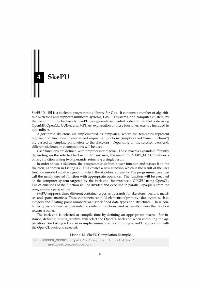
The back-end is selected at compile time by defining an appropriate macro. For in-stance, defining SKEPU_OPENCL will select the OpenCL back-end when compiling the ap-plication. See Listing 4.1 for an example command-line compiling a SkePU application withthe OpenCL back-end selected.
Listing 4.1: SkePU Compilation Example
c++ -DSKEPU_OPENCL -Ipath/to/skepu/include/folder \application_source.cpp
10
4.1. A Complete Example
4.1 A Complete Example
Listing 4.2: SkePU Dot Product Example
#include <iostream>
#include "skepu/vector.h"#include "skepu/mapreduce.h"
BINARY_FUNC(plus_f, int, a, b,return a + b;
)
BINARY_FUNC(mult_f, int, a, b,return a * b;
)
int main(){
skepu::MapReduce<mult_f, plus_f>dotProduct(new mult_f, new plus_f);
skepu::Vector<int> v1(500, 4);skepu::Vector<int> v2(500, 2);
int r = dotProduct(v1, v2);
std::cout << "Result: " << r << std::endl;
return 0;}
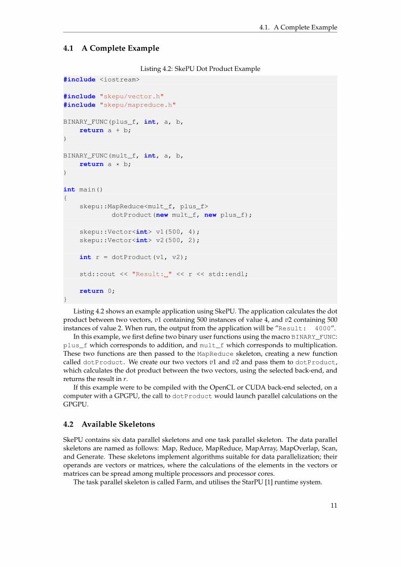
Listing 4.2 shows an example application using SkePU. The application calculates the dotproduct between two vectors, v1 containing 500 instances of value 4, and v2 containing 500instances of value 2. When run, the output from the application will be ”Result: 4000”.
In this example, we first define two binary user functions using the macro BINARY_FUNC:plus_f which corresponds to addition, and mult_f which corresponds to multiplication.These two functions are then passed to the MapReduce skeleton, creating a new functioncalled dotProduct. We create our two vectors v1 and v2 and pass them to dotProduct,which calculates the dot product between the two vectors, using the selected back-end, andreturns the result in r.
If this example were to be compiled with the OpenCL or CUDA back-end selected, on acomputer with a GPGPU, the call to dotProduct would launch parallel calculations on theGPGPU.
4.2 Available Skeletons
SkePU contains six data parallel skeletons and one task parallel skeleton. The data parallelskeletons are named as follows: Map, Reduce, MapReduce, MapArray, MapOverlap, Scan,and Generate. These skeletons implement algorithms suitable for data parallelization; theiroperands are vectors or matrices, where the calculations of the elements in the vectors ormatrices can be spread among multiple processors and processor cores.
The task parallel skeleton is called Farm, and utilises the StarPU [1] runtime system.
11

4.2. Available Skeletons
SkePU’s skeletons are explained below.
Map
Map applies a user function f of arity 1 ď k ď 3 to each element in k number of vectors vkeach of length n, and stores the result in a vector r. The mathematical expression of Map on avector is shown below.
r[i] = f (v1[i], v2[i], ..., vk[i])@i P 0, 1, ..., n´ 1
Map works in a similar way on matrices.
Reduce
Reduce cumulatively applies a binary user function as an operator 4 to each element in avector of length n, and stores the result in a scalar r. The mathematical expression of Reduceon a vector is shown below.
r = v[0]4 v[1]4 ...4 v[n´ 1]
Reduce works in a similar way on matrices. It also supports row-wise and column-wisereductions on matrices, where different user functions can be specified for rows and columns.
MapReduce
MapReduce is a combination of the Map skeleton and the Reduce skeleton. It first performsa Map operation with a user function f of arity 1 ď k ď 3, and then performs a Reduceoperation with an user operator 4 on the resulting vector. This results in a scalar r. Themathematical expression of MapReduce on a vector is shown below.
r = f (v1[0], ..., vk[0])4 ...4 f (v1[N ´ 1], ..., vk[n´ 1])
MapArray
MapArray is similar to Map, but as an addition, a vector v1 is passed to the user function.The mathematical expression of MapArray on a vector is shown below.
r[i] = f (v1, v2[i])@i P 0, 1, ..., n´ 1
MapOverlap
MapOverlap is also similar to Map, but as an addition, it allows the user function to ac-cess l number of neighbouring elements in each direction. The mathematical expression ofMapOverlap on a vector is shown below. Here, we use ”||” as symbol for list concatenation.
r[i] = f (v[i´ l]}v[i´ (l ´ 1)]}...}v[i]}...}v[i + (l ´ 1)]}v[i + l])@i P 0, 1, ..., n´ 1
MapOverlap also supports two-dimensional overlap on matrices, which makes it suitable forimage filtering.
12

4.3. Smart Containers
Scan
Scan performs a prefix sum with a binary user function, used as an operator 4, on a vectorv with length n. The result is stored in a vector r. The mathematical expression of Scan on avector is shown below.
r[i] = v[0]4 v[1]4 ...4 v[i]@i P 0, ..., n´ 1
Scan works in a similiar way on matrices.
Generate
Generate populates a vector r of length n, or a matrix R of dimensions nˆm, with the resultsof a user function f . The mathematical expressions of Generate on a vector and on a matrixare shown below.
r[i] = f (i)@i P 0, ..., n´ 1
R[i][j] = f (i, j)@i P 0, ..., m´ 1, j P 0, ..., n´ 1
Farm
Farm utilises the StarPU runtime system to run multiple skeletons in parallel, providing task-parallelism. Any skeleton, both the data-parallel skeletons, and Farm itself, can be used astasks in the Farm skeleton. It employs dynamic (run-time) scheduling and load-balancing ofpassed skeletons. Furthermore, Farm allows hybrid execution between different back-ends,so that skeletons for instance can be run in parallel on both the GPGPUs and the CPUs in aGPGPU system.
4.3 Smart Containers
Smart containers [5] is a feature of SkePU which provides automated memory handling invector and matrix containers when used as operands and results in systems where data mustbe transferred between different memories or devices, such as systems with one or moreGPGPUs. Smart containers ensures that data is synchronized between different memories,and devices, when needed, in a manner that is opaque to the programmer – the programmerof a SkePU application does not need to make any explicit calls to allocate memory or transferdata between devices.
Smart containers uses an optimization called lazy memory copying. Lazy memory copy-ing can reduce the number of redundant memory transfers between subsequent skeleton callsin SkePU applications. For instance on a GPGPU-based system, the result of a skeleton callis not copied back from the GPGPU memory to the computer’s main memory until it is actu-ally accessed by the main application. This avoids unnecessary transfers between the GPGPUmemory and the main memory when using subsequent skeleton calls in a pipeline.
4.4 Previous work on Myriad 1
Cuello presented a SkePU back-end [4] for the precursor of Myriad 2: Myriad 1. Myriad 1differs from Myriad 2 in a number of ways, the most notable being:
• The number of SHAVE processors is 8 instead of 12.
• The number of LEON processors is 1 instead of 2.
13
4.5. Related Work
• The LEON processor is big-endian instead of little-endian (SHAVE processors are little-endian in both versions).
The Myriad 1 back-end suffers from a number of problems. When the back-end wasimplemented, the MDK did not have a C++ compiler for the LEON processor. This preventsa SkePU application using the Myriad 1 back-end from running directly on the Myriad 1.Instead a PC host running the SkePU application is connected to the Myriad 1. Skeletonexecution is offloaded from the PC host to the Myriad 1’s SHAVE processors during run-timeand the LEON processor runs a simple C application which handles communication betweenthe PC host and the SHAVE processors.
The interface between the PC host and the Myriad 1 has a low throughput which causesthe communication time to dominate over actual computation time. Furthermore, the Myr-iad 1 back-end does not make use of the smart containers capability of SkePU, potentiallyleading to unnecessary communication between the PC host and the Myriad 1 over the slowinterface.
Additionally the LEON processor of the Myriad 1 differs in endianness from the SHAVEprocessors, complicating data transfers between the processors. As a consequence, the Myr-iad 1 back-end is limited to 32-bit integers and floating point numbers.
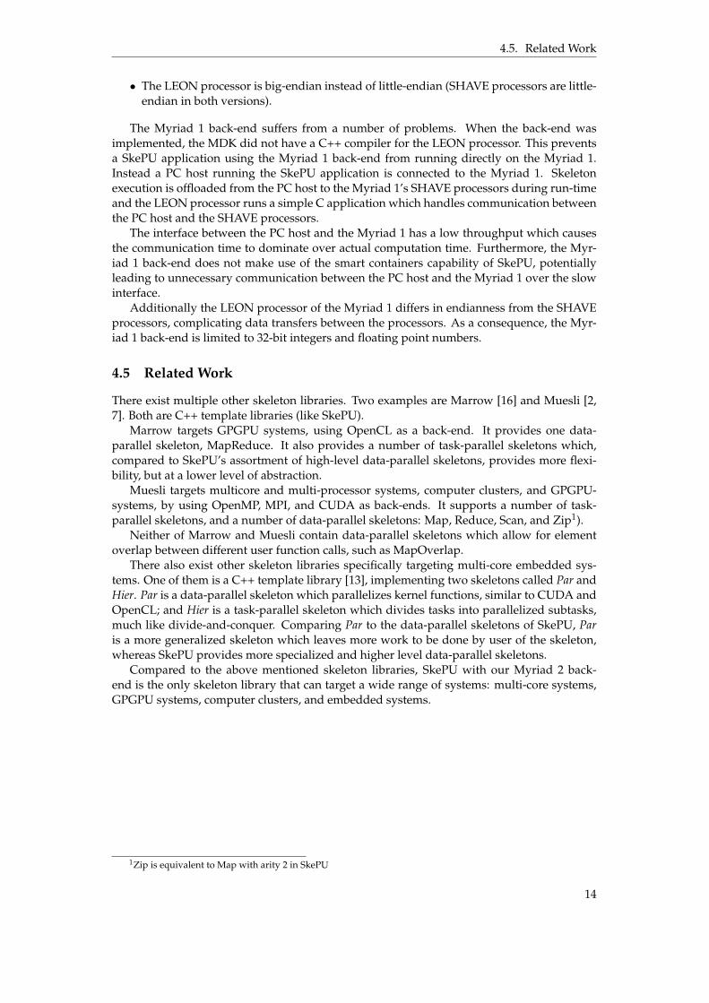
4.5 Related Work
There exist multiple other skeleton libraries. Two examples are Marrow [16] and Muesli [2,7]. Both are C++ template libraries (like SkePU).
Marrow targets GPGPU systems, using OpenCL as a back-end. It provides one data-parallel skeleton, MapReduce. It also provides a number of task-parallel skeletons which,compared to SkePU’s assortment of high-level data-parallel skeletons, provides more flexi-bility, but at a lower level of abstraction.
Muesli targets multicore and multi-processor systems, computer clusters, and GPGPU-systems, by using OpenMP, MPI, and CUDA as back-ends. It supports a number of task-parallel skeletons, and a number of data-parallel skeletons: Map, Reduce, Scan, and Zip1).
Neither of Marrow and Muesli contain data-parallel skeletons which allow for elementoverlap between different user function calls, such as MapOverlap.
There also exist other skeleton libraries specifically targeting multi-core embedded sys-tems. One of them is a C++ template library [13], implementing two skeletons called Par andHier. Par is a data-parallel skeleton which parallelizes kernel functions, similar to CUDA andOpenCL; and Hier is a task-parallel skeleton which divides tasks into parallelized subtasks,much like divide-and-conquer. Comparing Par to the data-parallel skeletons of SkePU, Paris a more generalized skeleton which leaves more work to be done by user of the skeleton,whereas SkePU provides more specialized and higher level data-parallel skeletons.
Compared to the above mentioned skeleton libraries, SkePU with our Myriad 2 back-end is the only skeleton library that can target a wide range of systems: multi-core systems,GPGPU systems, computer clusters, and embedded systems.
1Zip is equivalent to Map with arity 2 in SkePU
14

5 Design and Implementation ofthe Myriad 2 Back-End
The Myriad 2 back-end runs entirely on the Myriad 2, without the need for a PC host. Themain application runs on the LEON OS processor, and skeletons are loaded to and executedon the SHAVE processors dynamically during run-time. This approach was chosen to avoidsome of the problems experienced in the Myriad 1 back-end, stemming from the slow inter-face between the Myriad board and the PC: slow skeleton loading and data transfers duringskeleton execution.
In order to load SkePU applications to the Myriad 2, a PC is connected. However, nocommunication between the Myriad 2 and the PC is needed during the execution of the ap-plication. It is possible for the SkePU application running on the Myriad 2 to communicatewith the PC by printing standard output (stdout). Standard output is connected to a terminalon the PC while the SkePU application is running on the Myriad 2.
To better get an understanding of how the back-end is composed, we have divided itinto several parts. One of these parts is the build helpers, which helps building SkePU ap-plications for Myriad 2. The rest of these parts consist of source code which makes up theback-end, namely:
• Front-end and back-end glue.
• Hardware initialization.
• Skeleton setup (LEON side).
• Skeleton setup (SHAVE side).
• Skeleton implementations.
Figure 5.1 shows how SkePU, together with the different parts of the Myriad 2 back-end,and the programmer’s code, form an application that can run on Myriad 2.
5.1 Build Helpers
In order to simplify building and running Myriad 2 applications with SkePU, the back-endcontains a makefile which performs preparatory actions and configures the MDK build sys-tem. The MDK build system is automatically invoked by this makefile; the programmer onlyneeds to either use this makefile directly, or import it in a separate makefile.
15

5.1. Build Helpers
SkePU front-end
SkePUapplicationfor Myriad 2
Programmer'scode
User function code(extracted from
programmer's code)
Skeletonsetupcode
Hardwareinitialization
code
Skeletonimplementation
code
Skeletonsetupcode
Included into
Included into Included into
Included into
Compiled into Compiled into
Compiled into
LEON OS code SHAVE code
Front-end andback-end glue
Included into
Figure 5.1: Composition of a SkePU application for Myriad 2
The Myriad 2 back-end also contains a linker script which describes to the MDK buildsystem where in the memory different parts of the application should be placed.
Example
A SkePU application can be built for Myriad 2 with the command shown in Listing 5.1, andrun on Myriad 2 with the command shown in Listing 5.2.
Listing 5.1: Compiling a SkePU application for Myriad 2env MAKEFILES=path/to/skepu/include/folder/myriad.mk \
make SKEPU_MYRIAD_SOURCES=application_source.cpp all
Listing 5.2: Running a SkePU Application on Myriad 2env MAKEFILES=path/to/skepu/include/folder/myriad.mk \
make SKEPU_MYRIAD_SOURCES=application_source.cpp debug
The makefile rules ”all” and ”debug” are rules in the MDK build system which invokecompilation and execution respectivly.
Extraction of User Functions and Data Types
The source code of a SkePU application consists of one or more C++ source code files andheaders, where one or more files may contain definitions of user functions. This conflictswith a requirement of the MDK: the code for the LEON OS processor, and the code for theSHAVE processors, must be in separate files, as different compilers are used for LEON codeand SHAVE code. The user functions must be extracted from the SkePU application source
16

5.2. Front-End and Back-End Glue
code and inserted into a separate source code file compiled by the SHAVE compiler. This ishandled by a rule in the makefile which comes bundled with the Myriad 2 back-end. Therule performs the extraction before compilation.
User functions are defined with the help of preprocessor macros as described in Chapter4. When compiling a SkePU application for Myriad 2, these macros expand differently de-pending on the stage in the building process. Before compilation, the user function extractionrule is run, which in turn invokes the C preprocessor on the user’s source code files. Whenthe preprocessor expands a user function definition macro, the line is tagged with a specialsymbol: ”__skepu_myriad_shave__”. All lines starting with the special symbol are extractedfrom the SkePU application’s source code and inserted into a separate file, which is compiledtogether with the skeleton code by the SHAVE compiler in a later stage. When the LEONcompiler expands user function macros, they expand normally without being tagged withthe special symbol.
SkePU allows the programmer to use her own data structures (defined with the ”struct”keyword) as data types for skeleton function operands and results. The definition of thesedata types must also be extracted and inserted into the same file where user functions areinserted for the SHAVE compiler. To simplify extraction, the SkePU API is extended with aspecial macro to define data structures. This macro, like the user function definition macros,tags lines with the special ”__skepu_myriad_shave__” symbol when expanded with the Cpreprocessor during the user function extraction stage, so that the data structure definitionsare extracted together with the user function definitions. Listing 5.3 shows an example onhow a programmer can define a structure with the macro.
Listing 5.3: Defining a structure with the special macro// Structure describing a point in two dimensions.STRUCT(Point,
float x;float y;
)
5.2 Front-End and Back-End Glue
The front-end and back-end glue consist of code that integrates the Myriad 2 back-end intoSkePU. It connects SkePU’s front-end to the part of the back-end which invokes skeletonson the SHAVE processors. When a skeleton function is called, the program control will firstreach the SkePU front-end. The SkePU front-end will in turn call the selected back-end, andthe back-end will run the skeleton’s calculations on the back-end’s targeted computer system.We refer to the code which connects the Myriad 2 back-end to the front-end as glue.
5.3 Hardware Initialization
Myriad 2 requires the application to initialize the hardware, in order to use many of its fea-tures, such as using the SHAVE processors or starting DMA transfers. The Myriad 2 back-endcontains the necessary code for hardware initialization. When building a SkePU applica-tion for Myriad 2, this code will automatically be linked together with the resulting appli-cation. As the function performing the hardware initialization is not called by the program-mer’s code, it is added as an ”constructor” by annotating the function with the keyword__attribute__((constructor)). The constructor keyword is a non-standard keywordsupported by some C and C++ compilers, including the compiler for LEON. Having the hard-ware initialization function as a constructor will cause it to be called before the programmer’smain function is called.
The hardware initialization function performs a number of tasks, such as setting the clockrate and enabling interrupts. The hardware initialization function for the Myriad 2 back-end
17

5.4. Memory Layout
also disables clocks and power supply to components on the Myriad 2 chip which are unusedby the back-end, in order to decrease the power usage.
5.4 Memory Layout
The main application, running on the LEON OS processor, is loaded into, and run from, theDDR memory.
The skeleton code and data that make up the SHAVE applications, is stored in DDR mem-ory. When a skeleton is invoked, its code is copied from its storing area in the DDR memory,to a new, 1 kB aligned area also in the DDR memory. SHAVE applications use virtual ad-dresses for instructions, and the mapping between virtual and physical addresses requiresthe code to start on a 1 kB boundary. After the code has been copied, the SHAVE applicationdata (such as constants and predefined variables) is copied to each SHAVEs local CMX slice.
5.5 Skeleton Setup and Execution
When a skeleton is called, its SHAVE application is first loaded as described in Section 5.4.After loading, the program counter of each SHAVE processor is programmed to point to theloaded code, and one of the integer registers in each SHAVE processor is programmed with apointer to a structure of arguments called shaveArgs. shaveArgs contains pointers to theoperands, information about operand data types, and information about what user functionto insert into the skeleton.
After the SHAVEs have been loaded and configured according to the skeleton currentlycalled, they are started, and start parsing the argument structure shaveArgs. When aSHAVE processor has parsed shaveArgs, it continues to perform skeleton calculations, eachSHAVE working in parallel on a subset of the input operands. After a SHAVE completes itswork, it halts. During a skeleton call, the LEON OS processor waits for all SHAVEs to halt,before continuing execution of the main application.
Communication of Types and User Functions
In order to communicate data types and user functions between the LEON OS processor andthe SHAVE processors, each data type and user function is assigned a unique integer id.When a skeleton is invoked, these ids are put in the argument structure shaveArgs passedto the SHAVE processors.
On the SHAVE processors, templates are used to generate skeleton code for different datatypes and user functions. As the ids for data types and user functions are received as vari-ables, they cannot directly be used as template parameters; template parameters must beconstants, decidable at compile time. As a solution, template metaprogramming is used togenerate conditional calls to the function templates, with different parameters, for all possiblevalues and combination of ids.
Example
In Listing 5.4 we see an example of how a single operand input on the LEON OS processoris stored in the argument structure shaveArgs, along with its type id. The pointer of thisargument structure is passed to the SHAVE processors as they are started.
Listing 5.4: LEON OS side of passing a single operandshaveArgs.input = input;// getMyriadType maps the type of ‘input’ to its integer id.shaveArgs.inputType = getMyriadType<*input>::value;
18

5.5. Skeleton Setup and Execution
In Listing 5.5 we see an example of how a single operand input, along with its type id,is received on the SHAVE processors. The type id is converted to a template parameter withthe use of a templated function callWithTypes.
Listing 5.5: SHAVE side of receiving a single operandtemplate <InputType>void calculate(const InputType* input){
// Perform calculations...}
struct Thunk{
template <typename InputType>static void call(ShaveArgs* shaveArgs){// Cast input to its correct type and pass it to ‘calculate’.calculate(static_cast<const InputType*>(shaveArgs->input));
}};
// Convert ‘shaveArgs->inputType’ to a type and call ‘Thunk::call’ with// this type as an template parameter.callWithTypes<Thunk, 1>({ shaveArgs->inputType }, shaveArgs);
Listing 5.6 shows the expansion of the call to callWithTypes. A switch statement isgenerated which enumerates all valid types, generating a new call for each type.
Listing 5.6: Expansion of callWithTypesswitch (shaveArgs->inputType){
// Signed and unsigned types are merged into the same call.case S8:case U8:Thunk::call<uint8_t>(shaveArgs);break;
case S16:case U16:Thunk::call<uint16_t>(shaveArgs);break;
case S32:case U32:Thunk::call<uint32_t>(shaveArgs);break;
case S64:case U64:Thunk::call<uint64_t>(shaveArgs);break;
case FP32:Thunk::call<float>(shaveArgs);break;
default:// Invalid type.assert(false);
}
As some skeletons use multiple operands, callWithTypes supports multiple types inone call. For instance, the callcallWithTypes<Thunk, 2>({ inputType1, inputType2 }, input1, input2)would recursively generate nested switch statements (as callWithTypes is a recursivelytemplated function) to cover all combinations of types.
19

5.5. Skeleton Setup and Execution
Start transfer operands
Transfer complete
Start transfer results
Transfer complete
Start transfer operands
Start transfer results
Transfer complete
Transfer complete
ComputationsDMA
transfers
Start skeleton execution
Skeleton execution done
Iteration 1
Iteration 2
Figure 5.2: Synchronous streaming between DDR and CMX during skeleton execution
Streaming
Most skeletons stream operand data and results between the slower DDR memory and thefaster CMX memory. When streaming is used, operands and results are split into chunks,such that a single chunk can fit into a buffer in the CMX memory. Calculations are performediteratively on each chunk.
Asynchronous Streaming
Most skeletons use synchronous streaming, but some use asynchronous streaming to im-prove performance by overlapping data transfers with computations. In some skeletonswhere streaming is not feasible, the DDR memory is instead accessed through the SHAVEL1 and L2 caches. The skeletons which are using asynchronous streaming also have a corre-sponding implementation using synchronous streaming, which can be enabled by defining apreprocessor macro. This allows us to evaluate the difference in performance between syn-chronous streaming, and asynchronous streaming.
Figure 5.2 shows a sequence diagram of (2 iterations of) streaming during skeleton exe-cution for a skeleton using synchronous streaming. We see that the execution of the skeletonmust wait for DMA transfers to complete before being able to perform calculations.
Figure 5.3 shows a sequence diagram of (4 iterations of) streaming during skeleton execu-tion for a skeleton using asynchronous streaming. To allow for transfers to overlap computa-tions, two buffers (A and B) must be used. Note that it is possible to queue multiple transfersin order. For instance: one transfer from a buffer in the CMX memory to the DDR memorycan be followed by a transfer from the DDR memory to the same buffer in the CMX memory.
The speedup gained from using asynchronous streaming during a skeleton execution,compared to using synchronous streaming, is equal to the amount of time that computationsand DMA transfers can overlap in the particular skeleton execution. Figure 5.3 shows a fa-vorable scenario where the computation time is close to the DMA transfer time. Depending
20

5.6. Skeleton Implementation Code
Start transfer operands to A
Transfer to A complete
Transfers from/to A complete
Start transfer results from B
Transfers from/to B complete
ComputationsDMA
transfers
Start skeleton execution
Skeleton execution done
Start transfer operands to B
Transfer to B complete
Start transfer results from A
Queue transfer operands to A
Queue transfer operands to B
Start transfer results from A
Transfer from A complete
Iteration 1on buffer A
Iteration 2on buffer B
Iteration 3on buffer A
Iteration 4on buffer B
Start transfer results from B
Transfer from B complete
Figure 5.3: Asynchronous streaming between DDR and CMX during skeleton execution
on the user function that is used in a skeleton, it is possible for the computation time to besmaller than the DMA transfer time, which will cause the skeleton to still wait for DMAtransfers to complete, like in the synchronous case, reducing the overlap. It is also possiblefor the computation time to be greater than the DMA transfer time, also reducing the overlapbetween computations and DMA transfers. In both cases, asynchronous DMA transfers stillprovide a speedup, as there is still overlap, but the speedup is smaller than the case wherethe computation time is close to the DMA transfer time.
2D DMA
The CMX DMA engine support gather and scatter operations. The SkePU Myriad 2 back-end utilises this feature when using two-dimensional overlap in the MapOverlap skeleton.Matrices are stored row-wise in the DDR memory. When using two-dimensional overlap inthe MapOverlap, submatrices (called ”blocks”) of the operand matrix must be transferred toand from the CMX memory. In Figure 5.4 we see an example of how a submatrix is transferredfrom the DDR memory to the CMX memory using a gather operation. When a submatrix istransferred back from the CMX memory to the DDR memory, a scatter operation is used.
5.6 Skeleton Implementation Code
Listing 5.7 shows how unary Map skeleton is implemented in the SkePU Myriad 2 back-endas a templated C++ function. Synchronous DMA streaming is used in this implementation.
21

5.6. Skeleton Implementation Code
0 0 0 0 00 1 2 3 00 4 5 6 00 7 8 9 00 0 0 0 0
0 0 0 0 0 0 1 2 3 0 0 4 5 6 0 0 7 8 9 0 0 0 0 0 0
0 0 0 0 1 2 0 4 5
0 0 00 1 20 4 5
Matrix stored in DDR memory
Submatrix stored in CMX memory
DMA transfer
Figure 5.4: Using gather DMA to copy a submatrix from the DDR to CMX
The same skeleton implementation function is run on all 12 SHAVE processors, with the samearguments.
22

5.6. Skeleton Implementation Code
Listing 5.7: Unary Map Skeleton Calculation Implementationtemplate <typename Type, typename UserFunction>static void map(UserFunction& userFunction, const Type* operand, size_t size,
Type* result){
// Store the number of the SHAVE processor executing the code.unsigned shaveNumber = getCurrentShaveNumber();
// Create a buffer in the local CMX slice of the SHAVE processor executing// the code, used as a working memory for the skeleton calculation.Type buffer[BUFFER_SIZE / sizeof(Type)];
// Split the operand vector into to subvectors of ‘subSize’.size_t subSize = size / TOTAL_NUMBER_OF_SHAVE_PROCESSORS;
// If the operand size is not divisible by the total number of SHAVE// processors, distribute the remainder to the lowest numbered SHAVE// processors.if (shaveNumber < size % TOTAL_NUMBER_OF_SHAVE_PROCESSORS)subSize++;
// Store the offset for the subvector assigned to the SHAVE processor// executing the code.size_t subOffset =
size / TOTAL_NUMBER_OF_SHAVE_PROCESSORS * shaveNumber+ std::min(shaveNumber, size % TOTAL_NUMBER_OF_SHAVE_PROCESSORS);
// Split the subvector assigned to the SHAVE processor executing the code,// into chunks of ‘chunkSize’. ‘chunkSize’ denotes the maximum number of// vector elements that can fit in the buffer.size_t chunkSize = sizeof(buffer)/sizeof(Type);
// If the number of vector elements is larger than the number of the// SHAVE processor executing the code, that SHAVE processor does not take// part of the calculation.if (shaveNumber >= size)return;
// Loop over all elements in the subvector, one chunk at a time.for (int i = 0; i < subSize; i += chunkSize){// On the last iteration, the actual chunk size can be smaller if the size// of the subvector is not divisible by ‘chunkSize’. Account for this.size_t actualChunkSize = std::min(subSize - i, chunkSize);
// Copy one chunk of elements from the operand to the buffer, using a// synchronous DMA transfer.dmacpy(buffer, operand + subOffset + i, actualChunkSize * sizeof(Type));
// Loop over all elements in a chunk.for (int j = 0; j < actualChunkSize; j++){
// Apply the user function on a vector element.buffer[j] = userFunction(buffer[j]);
}
// Copy one chunk of results from the buffer to the result vector, using a// synchronous DMA transfer.dmacpy(result + subOffset + i, buffer, actualChunkSize * sizeof(Type));
}
The skeleton implementation function takes a user function, a vector operand and its size;and a result vector where the result is stored, as arguments. In Listing 5.7 we can see howthe user function is inserted into the algorithm. We can also see how the vector operand isdecomposed into subvectors and distributed among the SHAVE processors. In order for each
23

5.7. Smart Containers
SHAVE processor to work on different subvectors of the operand vector, the skeleton imple-mentation code uses a variable containing the number of the SHAVE processor executing thecode to differentiate between the SHAVE processors.
5.7 Smart Containers
This section (5.7) uses text from [21], c© 2016 IEEE, with permission.
In order to keep the caches on the Myriad 2 coherent, the smart containers feature of SkePUis used. The SHAVE level 2 cache is flushed and invalidated after each skeleton call, but theLEON OS level 1 cache is refreshed on-demand. If a vector that has been modified by theSHAVE processors is accessed by a LEON processor, the vector is refreshed by iterating overthe vector and refreshing each element with a special instruction that bypasses the cache.
Some skeletons, for instance MapArray, uses a portion in the CMX memory, which isshared by all SHAVE processors, to store either a vector or a matrix to be accessible by theskeleton’s user function during the entire execution of the skeleton. At the beginning ofskeleton call, the vector or matrix to be shared is copied from the DDR memory to the sharedportion of the CMX memory. To avoid redundant transfers to the shared memory duringsubsequent skeleton calls, smart containers are used to keep track of the state of the vector ormatrix currently having a copy in the shared memory.
5.8 Vector Operations
This section (5.8) uses text from [21], c© 2016 IEEE, with permission.
Movidius’ compiler [17] is capable of automatically generating SIMD instructions for codethat is operating on vectors, without the need for any special C extensions or inline assembler.This is called automatic vectorization.
Some skeletons are applicable for automatic vectorization, if they are combined with auser function which contains operations corresponding to available SIMD instructions. Toallow the compiler to perform automatic vectorization and generate SIMD instructions forsuch combinations, user functions are inlined into skeletons, instead of being called. Even ifa skeleton is not vectorizable, inlining user functions provides a performance increase as theoverhead of function calls is avoided.
24

6 Evaluation
To evaluate the performance and functionality of the SkePU Myriad 2 back-end, a number ofbenchmarks were performed. The benchmarks range from applications designed to to testdifferent aspects of the back-end, to already existing applications solving real-world prob-lems. We evaluate specific attributes of the back-end, such as performance scalability whenincreasing the number of SHAVE processors, and the speedup gained from asynchronousDMA streaming. We also evaluate if the back-end is able to run already existing SkePU appli-cations solving real-world problems and how well these applications scale when increasingthe number of SHAVE processors. The power consumption of the Myriad 2 system-on-a-chipwas measured for some of the applications, and compared to a PC equipped with a GPGPUrunning the same applications with the SkePU’s CUDA back-end.
Where not otherwise stated, benchmarks were performed on an MV0182-R4 evaluationboard, with a Myriad 2 system-on-a-chip version MA2150, clocked at 600 MHz. Results werereceived from the chip using a JTAG Debug Connector between a PC and the board.
6.1 Simple Skeleton Calls
Figure 6.1 shows the execution times for a unary Map on a vector of 106 elements, performingone binary shift per element, for different number of SHAVE processors. We can note that theexecution time for this benchmark scales poorly when using 4 or more SHAVE processors.The reason for this is that the DMA data streaming between the DDR memory and the CMXmemory becomes a bottleneck [21]. When this bottleneck is hit, the performance no longerchanges in a predictable way when increasing the number of SHAVE processors.
Figure 6.2 shows the execution times for a unary Map on a vector of 106 elements, takingthe square root for each element. This benchmark shows noticeably better scaling than theprevious example. When performing a more heavy computation per vector element, theDMA data streaming does not become a bottleneck.
Figure 6.3 shows the execution times for a Scan on a vector of 106 elements, calculating theprefix sums of the vector. We can note that using 2 SHAVE processors is slower than using 1SHAVE processor. The reason for this is that the algorithm behaviour changes when switch-ing from one to multiple processors. The sequential version of the algorithm only needs toaccess each vector element once; the parallel version needs to access each element twice. Afterusing more than 9 SHAVE processors, the DMA data streaming becomes a bottleneck.
25

6.1. Simple Skeleton Calls
3.3
3.4
3.5
3.6
3.7
3.8
3.9
4
4.1
1 2 3 4 5 6 7 8 9 10 11 12
Tim
e (
ms)
Number of SHAVE processors
Figure 6.1: Binary shift (unary Map) on 106 elements
0
50
100
150
200
250
300
350
400
450
500
1 2 3 4 5 6 7 8 9 10 11 12
Tim
e (
ms)
Number of SHAVE processors
Figure 6.2: Square root (unary Map) on 106 elements
6
8
10
12
14
16
18
20
22
1 2 3 4 5 6 7 8 9 10 11 12
Tim
e (
ms)
Number of SHAVE processors
Figure 6.3: Prefix sums (Scan) on 106 elements
26

6.1. Simple Skeleton Calls
50
100
150
200
250
300
350
400
450
500
1 2 3 4 5 6 7 8 9 10 11 12
Tim
e (
ms)
Number of SHAVE processors
Figure 6.4: Prefix sums with pythagorean addition (Scan) on 106 elements
Similar to the Map benchmarks (figures 6.1 and 6.2), the DMA data streaming bottleneckdoes not occur when performing a more heavy computation per element. We can see this inFigure 6.4 which shows the execution times of a prefix sum on 106 elements, where additionhas been replaced by pythagorean addition1.
Why the Bottleneck Occurs
We have two theories on why the DMA data streaming becomes a bottleneck when the com-putational intensity of each data element is low.
DDR Memory Bandwidth Saturation
One possibility is that the DDR memory bandwidth becomes saturated. The DDR memoryon the Myriad 2 chip runs at 533 MHz and is connected to a 32-bit bus. We can calculate thetheoretical bandwidth expressed in gigabytes per seconds with the following expression:
2 ¨ 533 ¨ 106 ¨ 328
10243 « 3.97
The Map and Scan benchmarks whose execution times are shown in figures 6.1 and 6.3, bothrun into the DMA data streaming bottleneck. The two benchmarks achieve data transferspeeds (between the DDR and the CMX memory) of at least 2.25 GB/s and 2.37 GB/s, re-spectively. We calculate this by dividing the amount of data transferred by the total execu-tion time, which gives a lower bound of the data transfer speeds. We can see that the Mapbenchmark achieves at least 57%, and the Scan benchmark at least 60%, of the theoreticalbandwidth. The Programmer’s Guide [19] in the MDK documentation states that a speedof 60%-70% of the theoretical bandwidth is expected. This leads us to believe that the DDRmemory bandwidth can be responsible for the bottleneck.
CMX DMA Engine
One other possibility is that too many DMA transfers are issued to the CMX DMA engine.When DMA data streaming is performed, all SHAVEs participating in a skeleton calculationare issuing transfers from and to their local CMX slices. To issue a DMA transfer, a lock mustbe held while communicating with the CMX DMA engine. When all 12 SHAVEs are issuingtransfers, lock contention could possibly decrease performance.
1Pythagorean addition is defined as aÀ
b =?
a2 + b2
27

6.1. Simple Skeleton Calls
2 3 4 5 6 7 8 9
10 11 12 13 14 15 16 17 18
1 2 3 4 5 6 7 8 9 10 11 12
Tim
e (
ms)
Number of SHAVE processors
600 MHz300 MHz100 MHz
Figure 6.5: Binary shift (unary Map) on 106 elements running on MA2450 with different clockspeeds
0
10
20
30
40
50
60
70
80
90
100
110
120
1 2 3 4 5 6 7 8 9 10 11 12
Tim
e (
ms)
Number of SHAVE processors
600 MHz300 MHz100 MHz
Figure 6.6: Prefix sums (Scan) on 106 elements running on MA2450 with different clockspeeds
The responsibility for issuing DMA transfers could be moved to the LEON OS processor,to reduce lock contention. In addition, gather and scatter operations could be used to sendand receive operands and results from all CMX slices in a single transfer, reducing the numberof DMA transfers issued. Improving the performance of DMA can however only increase theperformance towards the theoretical bandwidth of the DDR memory, not beyond it.
Testing the DDR Memory Bandwidth Saturation Theory
In order to test if DDR memory bandwidth saturation is the underlying reason for DMA datastreaming becoming a bottleneck, we have run the Map and Scan benchmarks on a newerversion of the Myriad 2 system-on-a-chip: MA2450.
MA2450, in contrast to MA2150 used in the other benchmarks, contains a faster DDRmemory. MA2450’s DDR memory runs at 933 MHz, which gives a theoretical memory band-width of 6.95 GB/s.
We have tested the Map and Scan applications running into the streaming bottleneck, onthree different processor clock speeds: 600, 300, and 100 MHz. 600 MHz is the default pro-cessor clock speed. Lowering the processor clock speed increases the relative DDR memoryspeed when compared to the processors’, as the DDR memory clock speed remains constant.
28

6.2. Different Memory Techniques
0
5
10
15
20
25
30
35
40
45
1 6 12
Tim
e (
ms)
Number of SHAVE processors
DMAmemcpy
direct
Figure 6.7: Different memory techniques for the Map skeleton.
0
100
200
300
400
500
600
700
800
900
1000
1100
1 6 12
Tim
e (
ms)
Number of SHAVE processors
DMAmemcpy
direct
Figure 6.8: Different memory techniques for the Generate skeleton.
Figures 6.5 and 6.6 show the Map and Scan benchmarks running on MA2450 at differentprocessor clock speeds. We can see that the DMA data streaming still becomes a bottleneck,even when lowering the processor clock speed.
On MA2450, the two benchmarks achieve data transfer speeds (between the DDR andthe CMX memory) of at least 2.80 GB/s and 2.85 GB/s, respectively. We calculate this bydividing the amount of data transferred by the fastest total execution time in figures 6.5 and6.6 respectively, which gives a lower bound of the data transfer speeds. This is only around40% of the theoretical DDR memory bandwidth.
This indicates that DDR memory bandwidth saturation is not the reason for DMA datastreaming becoming a bottleneck. Our other theory, that of issuing too many transfers to theCMX DMA engine, remains unproven.
29

6.2. Different Memory Techniques
2
4
6
8
10
12
14
16
18
1 2 3 4 5 6 7 8 9 10 11 12
Tim
e (
ms)
Number of SHAVE processors
SIMD disabledSIMD enabled (default)
Figure 6.9: SIMD speedup for binary shift (unary Map) on 106 elements.
6.2 Different Memory Techniques
As explained in Section 5.5, the SkePU Myriad 2 back-end streams data between the DDRmemory and the CMX memory, using the CMX memory as a working memory, where appli-cable. Other methods include transferring data between the DDR memory and CMX memoryusing a normal memory copy (for instance with the memcpy C standard function); and notusing the CMX memory at all, working directly on the DDR memory (through the SHAVEsL1 and L2 caches).
Figures 6.7 and 6.8 show the execution times of two different applications: one using theMap skeleton to perform a binary shift on 106 elements, and one using the Generate skeletonto calculate the Chebychev (chessboard) distances in a 4096x4096 matrix. Execution times fordifferent memory techniques and different number of SHAVE processors are shown. In thefigure, ”DMA” denotes using DMA to transfer data between the DDR and the CMX memory,”memcpy” denotes using a normal memory copy to transfer data between the DDR and theCMX memory; and ”direct” denotes performing calculations directly on the DDR memory,without transferring data to the CMX memory.
Using DMA transfers between the DDR memory and the CMX memory gives the bestperformance except in the case where the Generate application is run on only one SHAVEprocessor, where direct access of the DDR memory gives the best performance. It is likely thatthe overhead of copying data between the DDR memory and the CMX memory makes directaccess of the DDR memory more suitable in cases where memory utilization is low. Runningthe Generate application on only 1 SHAVE processor causes the time spent on calculations tobe high, and the memory utilization to be low.
6.3 Speedup of SIMD
Figures 6.9 and 6.10 show the reduction in execution time from the use of SIMD vectoriza-tion, for two different applications: a unary Map performing a binary shift on a vector of106 elements, and a matrix-vector multiplication on a 3072x3072 matrix using the MapArrayskeleton. In both applications, 32-bit elements are used, which allows each SHAVE processorto work on 4 elements at a time.
When using only one SHAVE processor, we see a 4.4 times speedup in Figure 6.9 (18 to 4.1ms) [21] and a 3.4 times speedup in Figure 6.10 (241 to 70 ms). When increasing the number ofSHAVE processors, the speedup decreases as the DMA data streaming becomes a bottleneck.
30

6.4. Speedup of Asynchronous DMA Streaming
0
50
100
150
200
250
1 2 3 4 5 6 7 8 9 10 11 12
Tim
e (
ms)
Number of SHAVE processors
SIMD disabledSIMD enabled (default)
Figure 6.10: SIMD speedup for matrix-vector multiplication (MapArray) with a 3072x3072matrix.
0
20
40
60
80
100
120
140
160
180
200
220
240
260
280
300
320
340
360
Map 1 Map 6 Map 12 Gen. 1 Gen. 6 Gen. 12
Tim
e d
iffe
rence (
ms)
Program and number of SHAVE processors
Function 1Function 2Function 3Function 4Function 5
Figure 6.11: Time difference between executing skeleton implementations using asyn-chronous DMA streaming, compared to executing skeleton implementations using syn-chronous streaming, for different user functions, skeletons and number of SHAVE processors.User function 1 performs the least amount of calculations; 5 the most.
6.4 Speedup of Asynchronous DMA Streaming
Figure 6.11 shows the reduction in execution time from the use of asynchronous DMA stream-ing, for unary Map and Generate using different user functions. The user functions range indifferent number of calculations per vector element, where the user function labeled 1 per-forms the least amount of calculations, and 5 the most. A higher user function number meansmore calculations; for instance, user function 3 performs more calculations than user function2. For each user function, skeleton, and number of SHAVE processors, an implementation ofthe corresponding skeleton using synchronous streaming is first run, followed by a run usingan implementation of the same skeleton using asynchronous streaming. The problem size
31
6.5. Using Different DMA Buffer Sizes
0
5
10
15
20
25
30
35
40
45
50
MA 1 MA 6 MA 12 G G 6 G 12 M 1 M 6 M 12
Tim
e (
ms)
Program and number of SHAVE processors
3 kB12 kB48 kB
Figure 6.12: Execution times using different DMA buffer sizes.
remains constant for each skeleton execution. The time differences between the runs usingasynchronous streaming and synchronous streaming are shown in Figure 6.11.
As described in Section 5.5, the speedup gained from asynchronous DMA streaming de-pends on the overlap between calculations and DMA transfers. By varying the number ofcalculations, the overlap between calculations and DMA transfers changes, leading to differ-ent speedups, as observed in Figure 6.11. If we for instance look at the Map skeleton runningon 1 SHAVE processor, we see that the time reduction caused by asynchronous streamingis almost the same for user functions 3, 4, and 5; which indicates that the overlap betweencalculations and DMA transfers is the same. When the time spent on calculations is increasedbeyond the time spent on DMA transfers (by increasing the number of calculations in theuser function), the overlap between calculations and DMA transfers remains constant.
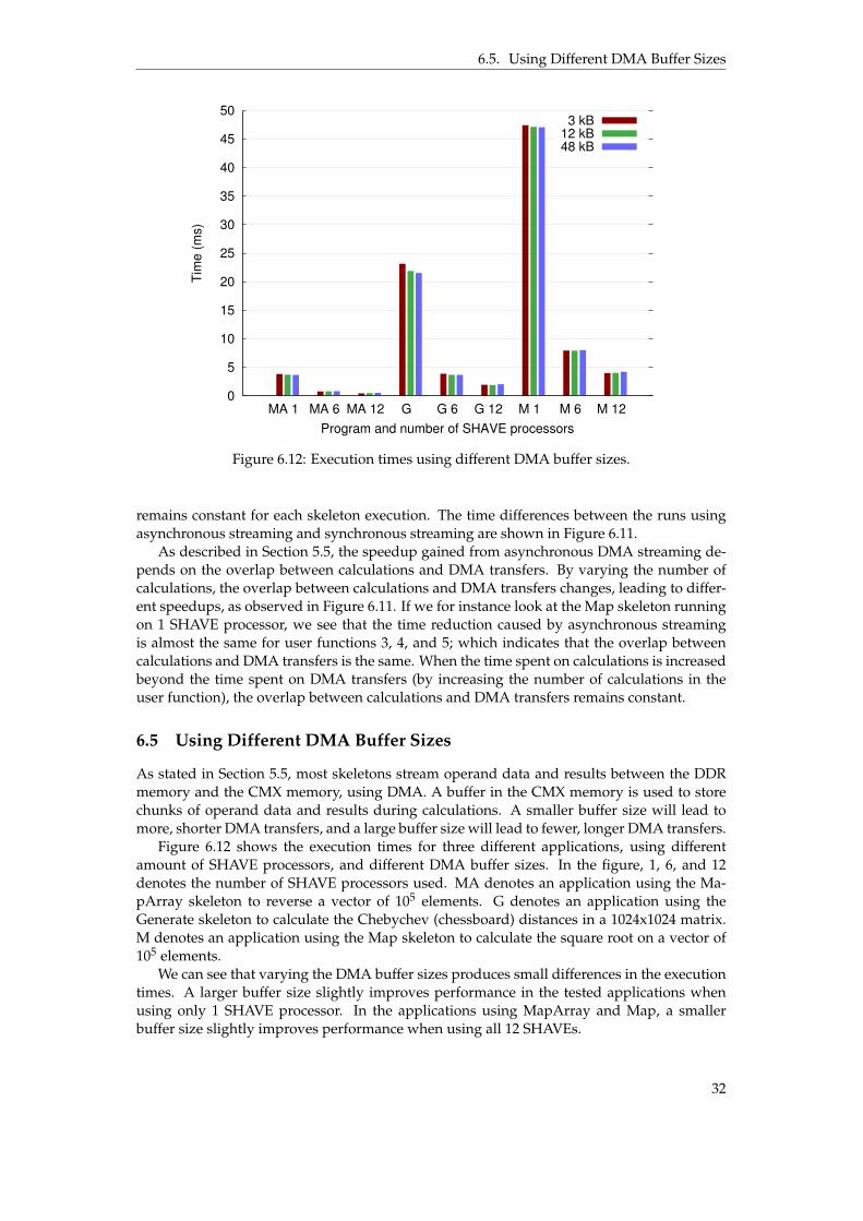
6.5 Using Different DMA Buffer Sizes
As stated in Section 5.5, most skeletons stream operand data and results between the DDRmemory and the CMX memory, using DMA. A buffer in the CMX memory is used to storechunks of operand data and results during calculations. A smaller buffer size will lead tomore, shorter DMA transfers, and a large buffer size will lead to fewer, longer DMA transfers.
Figure 6.12 shows the execution times for three different applications, using differentamount of SHAVE processors, and different DMA buffer sizes. In the figure, 1, 6, and 12denotes the number of SHAVE processors used. MA denotes an application using the Ma-pArray skeleton to reverse a vector of 105 elements. G denotes an application using theGenerate skeleton to calculate the Chebychev (chessboard) distances in a 1024x1024 matrix.M denotes an application using the Map skeleton to calculate the square root on a vector of105 elements.
We can see that varying the DMA buffer sizes produces small differences in the executiontimes. A larger buffer size slightly improves performance in the tested applications whenusing only 1 SHAVE processor. In the applications using MapArray and Map, a smallerbuffer size slightly improves performance when using all 12 SHAVEs.
32

6.6. SkePU Example Applications
0
500
1000
1500
2000
2500
3000
3500
4000
4500
1 2 3 4 5 6 7 8 9 10 11 12
Tim
e (
ms)
Number of SHAVE processors
Figure 6.13: LU decomposition on a 256x256 matrix.
0
1000
2000
3000
4000
5000
6000
7000
3x3 7x7 11x11 15x15
Tim
e (
ms)
Filter window size
1 SHAVE processor6 SHAVE processors
12 SHAVE processors
Figure 6.14: Median filtering on a 512x512 image (3 bytes per pixel). c© 2016 IEEE.
The default buffer size used in the SkePU Myriad 2 back-end is 12 kB. Note that using atoo large buffer size will reduce the available space for variables and constants in the skeletoncode and user functions, which can cause the space in the CMX memory to run out [21].
Using a too small buffer size can reduce performance in skeletons which require a mini-mum amount of buffer size in able to perform streaming. For instance, skeletons that applyuser functions on whole matrix rows, need a buffer that can contain a whole row, and willfall back to accessing the DDR memory directly (which is slower as shown in figures 6.7 and6.8) when a whole row cannot fit into the buffer.
6.6 SkePU Example Applications
SkePU is distributed with a number of example applications. The example applications rangefrom more simple ones, using a single skeleton to solve a problem, to more complex ones,using several different skeletons to solve different parts of a problem.
33

6.7. Energy Efficiency
0
1000
2000
3000
4000
5000
6000
7000
8000
9000
256 576 1024
Tim
e (
ms)
Number of particles
1 SHAVE processor6 SHAVE processors
12 SHAVE processors
Figure 6.15: SPH fluid dynamics shocktube simulation. c© 2016 IEEE.
Table 6.1: Energy Efficiency Comparison Between PC and Myriad 2. c© 2016 IEEE.
Application Time [ms] Power [W] Eff. [1/sW]512x512 LU decomposition on PC 48.90 130.9 0.1562512x512 LU decomposition on Myriad 2 4963 0.6899 0.3624SPH on 1024 particles on PC 177.4 103.8 0.05431SPH on 1024 particles on Myriad 2 843.5 0.6631 1.788Dot product between two 107 long vectors on PC 0.8436 76.53 15.49Dot product between two 107 long vectors on Myriad 2 32.68 1.047 29.23
A number of SkePU’s example applications were benchmarked on Myriad 2 using theMyriad 2 back-end [21]. Figure 6.13 shows the execution times for an example applicationperforming LU decomposition on a 256x256 matrix for different number of SHAVE proces-sors. Figure 6.14 shows the execution times for an example application performing medianfiltering on an image of 512x512 pixels, where each pixel consists of 3 bytes, for different num-ber of SHAVE processors and filter window sizes. Figure 6.15 shows the execution times foran example application performing an SPH fluid dynamics for different number of SHAVEprocessors and simulated particles. We see that the back-end can run already existing SkePUapplications, and the performance increases with the number of SHAVE processors used.
6.7 Energy Efficiency
The average power consumption of the Myriad 2 chip, and of a PC with a GPGPU, wasmeasured in three different SkePU example applications [21]. The PC contained an IntelXeon E5-2630L v2 CPU and an Nvidia Tesla K20c GPGPU. SkePU’s CUDA backend wasused on the PC. For the Myriad 2, an MV0198 power measurement daughter card was usedto measure the power consumption. For the PC system, the MeterPU [12] library was used tomeasure the aggregate power consumption of the CPU, DRAM, and GPGPU.
Table 6.1 shows the results from the measurements. Time, power, and efficiency areshown. Efficiency is calculated by 1
power¨time , where power ¨ time gives the power-delay prod-uct. All three tested SkePU applications runs slower, but use less energy, on the Myriad 2than on the PC.
34

7 Discussion
In this chapter we discuss the usefulness of our SkePU Myriad 2 back-end. We also drawconclusions based both on previous work on SkePU, and our work creating a SkePU back-end for Myriad 2. Finally, we propose 3 focus areas for future work.
7.1 Usefulness
Though our back-end does not reach the theoretical maximum performance for Myriad 2, theperformance should be enough to consider using SkePU when programming applicationstargeting Myriad 2. As we have not compared any SkePU applications to any equivalenthand-written Myriad 2 applications, it is still unclear how far our back-end is from achievingthe performance expected from Myriad 2. Doing a comparison between the performanceof the back-end and the theoretical maximum performance of Myriad 2 can be an unfaircomparison, as one does not necessarily reach maximum performance with a hand-writtenapplication. Nevertheless, the benchmarks we have performed in our evaluation of the back-end can give pointers on whether using SkePU for Myriad 2 is suitable for a particular case.
Our benchmarks have also shown that existing SkePU applications can run more energy-efficiently on Myriad 2 (with the Myriad 2 back-end) than on a GPGPU system. In caseswhere energy-efficiency is preferred over performance, one may want to choose to run anexisting SkePU application on Myriad 2 instead of another back-end.
7.2 Conclusions
The SkePU back-end for Myriad 1 shows that it is possible for SkePU to support a heteroge-neous multicore system-on-a-chip. Based upon this previous work, we have created a newand, performance-wise, improved SkePU back-end for Myriad 1’s successor: Myriad 2. Wehave argued for the usefulness of our new back-end, and shown that SkePU can achievedecent performance on Myriad 2. This in turn shows that SkePU, and algorithmic skeletonprogramming in general, is applicable to both supercomputer systems consisting of manyprocessors and GPGPUs; and low-power embedded systems such as Myriad 2.
35

7.3. Future Work
7.3 Future Work
Evaluation
In order to get a better understanding of the performance of our back-end, it is necessaryto make comparisons between SkePU applications and real-world hand-written applicationsfor Myriad 2. When making comparisons, it can also be useful to perform program profiling,to see where in the back-end overhead is produced.
DMA Data Streaming
We know from our evaluation that the DMA data streaming used in the back-end becomesa bottleneck when the amount of calculations done per data element is too small. The per-formance of the DMA data streaming can possibly be improved by redesigning how datastreaming is performed during skeleton execution, as explained in Section 6.1. However,changing how the data streaming is performed will require touching many parts of the back-end; additional evaluation of different streaming techniques should arguably be performedbefore making such a change.
Hardware Filters
Myriad 2 contains a number of high-performing hardware filters, such as sharpen filter andmedian filter. A median filter application could, instead of using the SHAVE processorsto perform the filter calculations, use the median filter that is included in the hardware,to achieve greater performance. For SkePU to utilise these hardware filters, user functionswhich correspond to available hardware filters would have to be identified before or duringthe compilation of SkePU applications.
36

A List of Common ApplicationProgramming Interfaces forDifferent Parallel ComputerSystems
• CUDA: Compute Unified Device Architecture. Used for programming applications forNvidia GPGPUs.
• MPI: Message Passing Interface. Used for programming applications for computerclusters.
• OpenCL: Open Computing Language. Used for programming applications for GPG-PUs, as well as digital signal processors, field-programmable gate arrays, and otherapplicable hardware.
• OpenMP: Open Multi-Processing. Used for programming applications for multicoreand multi-processor systems.
• pthreads: POSIX Threads. Used for programming applications for multicore and multi-processor systems adhering to the POSIX operating system interface standard.
37
Bibliography
[1] Cédric Augonnet, Samuel Thibault, Raymond Namyst, and Pierre-André Wacrenier.“StarPU: A Unified Platform for Task Scheduling on Heterogeneous Multicore Archi-tectures”. In: Concurr. Comput. : Pract. Exper. 23.2 (Feb. 2011), pp. 187–198. ISSN: 1532-0626. DOI: 10.1002/cpe.1631. URL: http://dx.doi.org/10.1002/cpe.1631.
[2] Philipp Ciechanowicz, Michael Poldner, and Herbert Kuchen. The Münster Skeleton Li-brary Muesli: A comprehensive overview. ERCIS Working Papers 7. University of Mün-ster, European Research Center for Information Systems (ERCIS), 2009. URL: http://EconPapers.repec.org/RePEc:zbw:ercisw:7.
[3] Murray Cole. Algorithmic Skeletons: Structured Management of Parallel Computation. Cam-bridge, MA, USA: MIT Press, 1991. ISBN: 0-262-53086-4.
[4] Rosandra Cuello. “Providing Support for the Movidius Myriad1 Platform in the SkePUSkeleton Programming Framework”. MA thesis. Linköping University, The Institute ofTechnology, 2014, p. 60.
[5] Usman Dastgeer and Christoph Kessler. “Smart Containers and Skeleton Programmingfor GPU-Based Systems”. In: Int. J. Parallel Program. 44.3 (June 2016), pp. 506–530. ISSN:0885-7458. DOI: 10.1007/s10766-015-0357-6. URL: http://dx.doi.org/10.1007/s10766-015-0357-6.
[6] Johan Enmyren and Christoph W. Kessler. “SkePU: A Multi-backend Skeleton Pro-gramming Library for multi-GPU Systems”. In: Proceedings of the Fourth InternationalWorkshop on High-level Parallel Programming and Applications. HLPP ’10. Baltimore,Maryland, USA: ACM, 2010, pp. 5–14. ISBN: 978-1-4503-0254-8. DOI: 10 . 1145 /1863482.1863487. URL: http://doi.acm.org/10.1145/1863482.1863487.
[7] Steffen Ernsting and Herbert Kuchen. “Algorithmic Skeletons for Multi-core, multi-GPU Systems and Clusters”. In: Int. J. High Perform. Comput. Netw. 7.2 (Apr. 2012),pp. 129–138. ISSN: 1740-0562. DOI: 10.1504/IJHPCN.2012.046370. URL: http://dx.doi.org/10.1504/IJHPCN.2012.046370.
[8] Song Huang, Michael Lang, Scott Pakin, and Song Fu. “Measurement and Characteri-zation of Haswell Power and Energy Consumption”. In: Proceedings of the 3rd Interna-tional Workshop on Energy Efficient Supercomputing. E2SC ’15. Austin, Texas: ACM, 2015,7:1–7:10. ISBN: 978-1-4503-3994-0. DOI: 10.1145/2834800.2834807. URL: http://doi.acm.org/10.1145/2834800.2834807.
38

Bibliography
[9] Intel. Optimizing Performance with Intel Advanced Vector Extensions. Tech. rep. 2014.URL: http : / / www . intel . com / content / dam / www / public / us / en /documents/white-papers/performance-xeon-e5-v3-advanced-vector-extensions-paper.pdf.
[10] Christoforos Kozyrakis and David Patterson. “Vector vs. Superscalar and VLIW Ar-chitectures for Embedded Multimedia Benchmarks”. In: Proceedings of the 35th AnnualACM/IEEE International Symposium on Microarchitecture. MICRO 35. Istanbul, Turkey:IEEE Computer Society Press, 2002, pp. 283–293. ISBN: 0-7695-1859-1. URL: http://dl.acm.org/citation.cfm?id=774861.774892.
[11] LEON4 32-bit processor core. URL: http://www.gaisler.com/doc/LEON4_32-bit_processor_core.pdf.
[12] Lu Li and Christoph Kessler. “MeterPU: A Generic Measurement Abstraction API En-abling Energy-Tuned Skeleton Backend Selection”. In: Proceedings of the 2015 IEEE Trust-com/BigDataSE/ISPA - Volume 03. TRUSTCOM-BIGDATASE-ISPA ’15. Washington, DC,USA: IEEE Computer Society, 2015, pp. 154–159. ISBN: 978-1-4673-7952-6. DOI: 10.1109/Trustcom.2015.625. URL: http://dx.doi.org/10.1109/Trustcom.2015.625.
[13] X. Liu, J. Zhou, D. Zhang, Y. Shen, and M. Guo. “A Parallel Skeleton Library for Embed-ded Multicores”. In: 2010 39th International Conference on Parallel Processing Workshops.Sept. 2010, pp. 65–73. DOI: 10.1109/ICPPW.2010.21.
[14] MA2x5x SIPP User Guide v1.0. Movidius Ltd. 2015.
[15] Mudassar Majeed, Usman Dastgeer, and Christoph Kessler. “Cluster-SkePU: A Multi-Backend Skeleton Programming Library for GPU Clusters”. In: Proceedings of the In-ternational Conference on Parallel and Distributed Processing Techniques and Applications(PDPTA-2013), : 2013.
[16] Ricardo Marques, Hervé Paulino, Fernando Alexandre, and Pedro D. Medeiros. “Al-gorithmic Skeleton Framework for the Orchestration of GPU Computations”. In: Pro-ceedings of the 19th International Conference on Parallel Processing. Euro-Par’13. Aachen,Germany: Springer-Verlag, 2013, pp. 874–885. ISBN: 978-3-642-40046-9. DOI: 10.1007/978-3-642-40047-6_86. URL: http://dx.doi.org/10.1007/978-3-642-40047-6_86.
[17] moviCompile, Movidius Compiler 00.50.69.4. Movidius Ltd. 2015.
[18] Myriad 2 Datasheet v1.06. Movidius Ltd. 2015.
[19] Myriad 2 Development Kit, Programmers Guide v1.8. Movidius Ltd. 2015.
[20] Myriad 2 Product Brief. Movidius Ltd. 2014. URL: http://uploads.movidius.com/1441734401-Myriad-2-product-brief.pdf.
[21] Sebastian Thorarensen, Rosandra Cuello, Christoph Kessler, Lu Li, and Brendan Barry.“Efficient Execution of SkePU Skeleton Programs on the Low-Power Multicore Pro-cessor Myriad2”. In: 2016 24th Euromicro International Conference on Parallel, Distributed,and Network-Based Processing (PDP). Feb. 2016, pp. 398–402. DOI: 10.1109/PDP.2016.123.
39