a! · 5.3.3 pdcch symbols mapping ... list of notations . ... (abs) to mitigate femto-cell to macro...
TRANSCRIPT
A! Aalto University School of Electrical Engineering Department of Communications and Networking
Control Channel Interference Measurement in LTE-TDD Heterogeneous Network
Guo Chen
Master Thesis submitted in partial fulfilment of the requirements for the Degree of Master of Science in Technology
Espoo, May 2015
Supervisor: Professor Olav Tirkkonen
Instructor: D.Sc Kalle Ruttik

ii
Aalto University Abstract of the Master’s Thesis
Author: Guo Chen
Title:
Control Channel Interference Measurement in LTE-TDD Heterogeneous Network
Date: May 2015 Number of pages: 61
Faculty: Electronics, Communications and Automation
Professorship: S-72 Communications Engineering
Supervisor: Professor Olav Tirkkonen
Instructor: D.Sc Kalle Ruttik
Abstract
Deploying low power eNodeBs inside macro-cells is an effective way to enhance
indoor coverage. By reusing frequency between macro-cells and indoor femto-cells,
the efficiency of expensive licensed spectrum can be further increased. This thesis
measured Physical Downlink Control Channel (PDCCH) performance in such a
heterogeneous LTE-TDD network. Four USRP software radio terminals and
connected Linux workstations were deployed to build a test environment. They acted
as eNodeB and UE respectively. During the test, the femto-cell was configured to
coordinate its radio frame with the macro-cell. Several criteria including received block
error rate, payload bit error rate and symbols signal to interference and noise ratio
were used to evaluate the PDCCH performance in macro-cell under heterogeneous
environment.
Keywords: PDCCH, femto-cell, heterogeneous, co-channel, eNodeB,
LTE-TDD, block error rate, aggregation level

iii
Acknowledgement
This thesis is carried out as part of the work in End-to-End Cognitive Radio Testbed
(EECRT) project of Department of Communications and Networking, Aalto University.
At the beginning, I would like to express my thanks to my supervisor, Prof. Olav
Tirkkonen, for his guidance of this thesis and offering me the opportunity to work in this
project. Furthermore, I wish to express my great gratitude to my instructor, D.Sc. Kalle Ruttik,
for providing me lots of valuable advice and comments both in the thesis as well as my RA
works in the department. Thanks to their help I can finally finish this thesis. This precious
experience will benefit me for a long time.
In addition, I would also like to thank Nicolas Malm, Yihenew Beyene and Jussi Kerttula
for the help they gave when we worked together in this project.
At last, thanks to my family and all the friends that support and encourage me during
this time.
Stockholm, 08 May 2015
Guo Chen

iv
Contents
List of Abbreviations ............................................................................................. vi
List of Notations ................................................................................................... ix
List of Figures ......................................................................................................... x
List of Tables ........................................................................................................ xii
Chapter 1 Introduction ....................................................................................... 1
1.1 Scope of the thesis ................................................................................................. 2
1.2 Thesis Organization ................................................................................................ 3
Chapter 2 Model of LTE Heterogeneous Network ............................................... 4
2.1 Femto-Cell Structure .............................................................................................. 4
2.2 Femto-Cell and Macro-Cell Overlaid Heterogeneous Network ............................. 5
2.3 Recent Research on Femto-Cell Overlaid Heterogeneous Network ...................... 7
Chapter 3 Downlink OFDM Transmission in LTE ................................................. 10
3.1 Principle of OFDM ................................................................................................ 10
3.2 OFDM Encoding and Decoding in LTE .................................................................. 12
Chapter 4 LTE Physical Layer Concepts............................................................... 15
4.1 LTE Physical Frame Structure ............................................................................... 15
4.2 REG and CCE ......................................................................................................... 19
Chapter 5 LTE DL Physical Channel Structure ..................................................... 21
5.1 PCFICH .................................................................................................................. 21
5.2 PHICH .................................................................................................................... 23
5.3 PDCCH ................................................................................................................... 26
5.3.1 DCI ........................................................................................................... 27
5.3.2 DCI Channel Coding and Rate Matching .................................................. 28
5.3.3 PDCCH Symbols Mapping ........................................................................ 31
5.4 PDSCH ................................................................................................................... 35

v
Chapter 6 UE Downlink Decoding Procedures .................................................... 36
Chapter 7 LTE-TDD Heterogeneous Network Implementation ............................ 40
7.1 Co-Channel Heterogeneous Environment Setup ................................................. 40
7.2 USRP Based Implementation ................................................................................ 42
7.3 Control Group with Single eNodeB ...................................................................... 44
Chapter 8 Measurement and Result Analysis ..................................................... 45
8.1 Measurement Configuration ................................................................................ 45
8.2 PDCCH in Single eNodeB Scenario ........................................................................ 47
8.3 Macro-cell PDCCH in Heterogeneous Network .................................................... 49
8.4 Improvement on Test and Further Measurement ............................................... 55
Chapter 9 Conclusion ........................................................................................ 57
Reference ............................................................................................................ 59

vi
List of Abbreviations
BER Bit Error Rate
BLER Block Error Rate
BS Base Station
CCE Control Channel Element
CDF Cumulative Distribution Function
CFI Control Format Indicator
CP Cyclic Prefix
CQI Channel Quality Indication
CRC Cyclic Redundancy Check
CRS Cell-specific Reference Symbol
CSG Closed Subscriber Group
DCI Downlink Control Information
DL Downlink
DMRS Demodulation Reference Signal in PUSCH
FDD Frequency Division Duplex
FDM Frequency Division Multiplexing
FFT Fast Fourier transform
GPP General Purpose Processor
vii
PBCH Physical Broadcast Channel
PCFICH Physical Control Format Indicator Channel
PDCCH Physical Downlink Control Channel
PDSCH Physical Downlink Shared Channel
PHICH Physical Hybrid-ARQ Indicator Channel
PSS Primary Synchronization Signal
PUCCH Physical Uplink Control Channel
PUSCH Physical Uplink Shared Channel
RB Resource Block
RE Resource Element
REG Resource Element Group
RNTI Radio Network Temporary Identifier
RSRP Reference Signal Received Power
SC-FDMA Single Carrier-Frequency Division Multiple Access
SIMO Single Input Multiple Output
SINR Signal to Interference plus Noise Ratio
SSS Secondary Synchronization Signal
IFFT Inverse fast Fourier transform
ISP Internet Service Provider
LTE Long Term Evolution
MBSFN Multicast Broadcast Single Frequency Network
MIMO Multiple Input Multiple Output
MUE Macro-cell User Equipment
OFDM Orthogonal Frequency Division Multiplexing
viii
TDD Time Division Duplex
TPC Transmit Power Control
UE User Equipment
UL Uplink
USRP Universal Software Radio Peripheral
3GPP The 3rd Generation Partnership Project
ix
List of Notations
𝑔𝐶𝐶𝐶16(𝐷) Cyclic generator polynomial for 16-bit Cyclic Redundancy Check
𝑁𝐶𝑅𝐷𝐷 Downlink bandwidth configuration, expressed in multiples of 𝑁𝑠𝑠𝐶𝑅
𝑁𝐶𝑅𝑈𝐷 Uplink bandwidth configuration, expressed in multiples of 𝑁𝑠𝑠𝐶𝑅
𝑁𝑠𝑠𝐶𝑅 Resource block size in the frequency domain, expressed as a number of subcarriers
𝑁𝑠𝑠𝑠𝑠𝐷𝐷 Number of OFDM symbols in a Downlink slot
𝑁𝐼𝐷𝑠𝑐𝑐𝑐 Physical layer cell identity
𝑛𝑃𝑃𝐼𝐶𝑃𝑔𝑔𝑔𝑔𝑔
PHICH group index
𝑛𝑃𝑃𝐼𝐶𝑃𝑠𝑐𝑠
PHICH Orthogonal sequence index

x
List of Figures
2.1: Connection of typical femto-cell and macro-cell to the operator core network ............ 4
2.2: An example structure of LTE heterogeneous network ................................................... 5
2.3: Radio resource share scheme between femto-cell and macro-cell ................................ 6
2.4: Femto-cell control region sparseness for interference control ...................................... 8
2.5: Using Almost Blank Subframe (ABS) to mitigate femto-cell to macro-cell interference 8
3.1: Spectrum of OFDM subcarriers ..................................................................................... 10
3.2: A typical OFDM modulation and demodulation system ............................................... 11
3.3: OFDM encoder with cyclic prefix .................................................................................. 13
3.4: OFDM decoder with cyclic prefix .................................................................................. 13
3.5: Cyclic Prefix concept ...................................................................................................... 14
4.1: LTE radio frame structure .............................................................................................. 15
4.2: LTE-TDD Downlink subframe resource grid .................................................................. 17
4.3: Relation between LTE channel bandwidth and transmission bandwidth. .................... 18
4.4: Control region and data region of a subframe .............................................................. 19
5.1: PCFICH processing procedures ...................................................................................... 22
5.2: PHICH processing procedures (Normal Cyclic Prefix example) ..................................... 25
5.3: PDCCH physical layer procedures.................................................................................. 26
5.4: 1/3 Code Rate Tail Biting Convolutional Encoder ......................................................... 29
5.5: Interleaving and bit collection blocks of PDCCH ........................................................... 30
5.6: REG indexing and CCE calculation for PDCCH ............................................................... 32
5.7: A PDCCH searching space example ............................................................................... 34
5.8: PDSCH physical layer procedures .................................................................................. 35
6.1: UE Downlink physical layer decoding procedures ........................................................ 36
xi
7.1: Overlaid co-channel transmission test scenario ........................................................... 40
7.2: USRP based eNodeB and UE implementation............................................................... 42
7.3: Device connections to model co-channel transmission ................................................ 43
7.4: Single eNodeB transmission scenario ........................................................................... 44
8.1: PDCCH symbol SINR (𝐸𝐸/𝑁𝑁) CDF (single eNodeB) ...................................................... 48
8.2: PDCCH payload (DCI bits) BER CDF (single eNodeB) ..................................................... 48
8.3: PDCCH BLER (single eNodeB) ........................................................................................ 48
8.4: Spectrogram of overlapped DL subframe of HeNodeB and MeNodeB-1 ..................... 49
8.5: PDCCH symbol SINR (𝐸𝐸/𝑁𝑁) CDF (use PDCCH aggregation level 1) ............................ 50
8.6: PDCCH payload (DCI bits) BER CDF (use PDCCH aggregation level 1) ........................... 50
8.7: PDCCH BLER (use PDCCH aggregation level 1) .............................................................. 51
8.8: PDCCH symbol SINR (𝐸𝐸/𝑁𝑁) CDF (use PDCCH aggregation level 2) ............................ 51
8.9: PDCCH payload (DCI bits) BER CDF (use PDCCH aggregation level 2) ........................... 51
8.10: PDCCH BLER (use PDCCH aggregation level 2) ............................................................ 52
8.11: PDCCH symbol SINR (𝐸𝐸/𝑁𝑁) CDF (use PDCCH aggregation level 4) .......................... 52
8.12: PDCCH payload (DCI bits) BER CDF (use PDCCH aggregation level 4) ......................... 52
8.13: PDCCH BLER (use PDCCH aggregation level 4) ............................................................ 53
8.14: PDCCH symbol SINR (𝐸𝐸/𝑁𝑁) CDF (use PDCCH aggregation level 8) .......................... 53
8.15: PDCCH payload (DCI bits) BER CDF (use PDCCH aggregation level 8) ......................... 53
8.16: PDCCH BLER (use PDCCH aggregation level 8) ............................................................ 54
8.17: HeNodeB asynchronous working mode test scenario ................................................ 56
xii
List of Tables
4.1: LTE-TDD Uplink-Downlink configurations [21] .............................................................. 16
4.2: LTE transmission bandwidth configurations ................................................................. 19
5.1: Number of OFDM symbols for control region............................................................... 21
5.2: CFI code words [21] ....................................................................................................... 22
5.3: Factor 𝑚𝑚 for LTE-TDD configurations [21] ................................................................. 24
5.4: Orthogonal sequence for PHICHs in the same group [21] ............................................ 24
5.5: Supported PDCCH formats ............................................................................................ 27
5.6: 3GPP LTE release-8 supported DCI format and corresponding usage area .................. 27
5.7: Common and UE-Specific searching space size [30] ..................................................... 33
8.1: DCI bits size used under different aggregation levels in our test ................................. 46
8.2: Environment variables in our test ................................................................................. 46

Control Channel Interference Measurement in LTE-TDD Heterogeneous Network
1
Chapter 1
Introduction
The next generation cellular system is aiming to support massive number of users with
simultaneous access, as well as to provide extremely high data rates within the coverage
area. The way to expand system capacity or increase spectrum efficiency is the key
challenges for the new system. Methods like Carrier Aggregation [1] are introduced in 3GPP
LTE Release-10 for expanding the total bandwidth in usage. Up to 100MHz bandwidth can be
aggregated from several component carriers [2]. However, considering the cost of
purchasing licensed frequency spectrum and disposing several antennas for individual
carriers, physically expanding bandwidth still has its limitation in providing high capacity
efficiently. Moreover, for a normal homogeneous network contains only macro-cell, it is
hard to expand the number of base stations (BS) and antennas in urban areas due to the
difficulty in acquisition of appropriate sites [3].
A survey in [4] reveals that more than half of voice calls and data transmission happens
in an indoor scenario. An improved deployment topology is needed for fulfilling this kind of
requirement. Placing femto-cells in buildings inside macro-cells will be an effective way to
provide high capacity indoor coverage. It can also solve coverage hole problems due to
penetration loss of the radio link from conventional macro-cell BS to indoor User Equipment
(UE) – radio signals are attenuated in the walls of the buildings. The femto-cell will use short
range and low power BS, i.e. HeNodeB.
The overlaid femto-cells and macro-cells compose a Heterogeneous Network. In such a
network, the co-existing femto-cells and macro-cells form a multi-tier architecture.
Macro-cell BSs serve outdoor connections. Meanwhile, femto-cell BSs are deployed inside
the macro-cell coverage area, serving indoor users. The penetration loss also mitigates the
indoor-to-outdoor interference. Not only benefiting the indoor connection data rate, by
offloading part of traffic burden from outdoor BS, the heterogeneous structure can also
ensure more radio resources to outdoor connections, thereby boosting the whole network
performance.

Control Channel Interference Measurement in LTE-TDD Heterogeneous Network
2
Furthermore, spatial reuse of the same frequency between indoor and outdoor, or take
a so-called “co-channel” deployment, will lead to an efficient approach for capacity
enhancement [5].
However, a major drawback of heterogeneous networks is inter-cell interference [6],
which can lead to significant performance loss. Interference avoidance requires
sophisticated interference management between femto-cell and macro-cell. Besides, a
femto-cell usually serves only a predefined set of users, which locate within its coverage
area. They are maintained in a list called closed subscriber group (CSG). Users outside the
group are refused access to the femto-cell BS, even if they are closer to it rather than to
macro-cell BS. Users not allowed to connect to femto-cell are more vulnerable to the
inter-cell interference. Another detrimental aspect is the indirect connection between
femto-cell BS and operator’s core network, which is usually via user’s broadband link. It
limits the backhaul signaling quantity and reliability for interference coordination [7].
1.1 Scope of the thesis Research on heterogeneous networks has paid much attention to interference
coordination between macro-cells and femto-cells. In heterogeneous networks with
co-channel deployment, interferences can be divided into control channels interference and
data channel interference. LTE control channels carry connection signaling and resource
grant information. They only occupy a small part of the radio resource but are vital for
establishing the data connection. From a system operation point of view, it is critical to have
good reception quality of control channels. Failure in decoding control signaling will also
disable the access of data channels. Physical Downlink Control Channel (PDCCH) is the most
important control channel in LTE. It carries the Downlink Control Information (DCI) as
payload and is convolutionally encoded. Convolutional codes are weaker than turbo codes
that are used by data channels. Hence, identifying how well the PDCCH can sustain the
inter-cell interference in a heterogeneous network is crucial.
The reliance of control channel performance against interference in the heterogeneous
network is usually studied with simulations or with theoretical modeling. In this thesis, we
measure how inter-cell interference impacts the PDCCH performance in a realistic
environment that is built by using Universal Software Radio Peripheral (USRP) frontends.
The USRP shifts signals to and from radio frequencies. The baseband functionalities are
implemented in Linux workstations by software. Such software defined radio (SDR) platform
provides flexible and configurable radio test environment. In our test, one USRP and one
connected Linux workstation compose a basic node, performs functionalities of an LTE BS

Control Channel Interference Measurement in LTE-TDD Heterogeneous Network
3
(eNodeB) or a UE. Several nodes are deployed at the same time to form the heterogeneous
network environment.
In a heterogeneous network, macro-cell UEs are more vulnerable to the inter-cell
interference in some circumstances, compared to femto-cell UEs. For example, when a
macro-cell UE moves indoor or stays much closer to the HeNodeB than the macro-cell
eNodeB, it will receive strong interference from femto-cell while being served by a distant
macro-cell eNodeB. It may severely worsen macro-cell UE user experience. Therefore, it is
very interesting to focus on the potential macro-cell PDCCH performance degradation
brought by inter-cell interference in a heterogeneous network.
In the thesis, the macro-cell PDCCH reception quality at the macro-cell UE will be
measured under different inter-cell interference levels. The PDCCH block error rate (BLER)
and payload bit error rate (BER) will be used as criteria to reveal the relation between
PDCCH performance and co-channel inter-cell interference.
1.2 Thesis Organization
The thesis starts with the brief explanation of LTE heterogeneous network and reviews
the recent research on inter-cell interference management methods. Chapter 3 explains
how OFDM is used in LTE Downlink transmission. In Chapter 4, LTE-TDD physical layer
concepts are described. The physical layer channels structures and mappings are introduced
in Chapter 5. Chapter 6 interprets the Downlink physical layer channels decoding methods
and procedures. Chapter 7 gives the implementation of a USRP based heterogeneous
network test environment. Followed by Chapter 8, it presents the measurement results on
PDCCH in the heterogeneous network and corresponding analysis. An improved model is
also proposed for conducting future measurement. At last, Chapter 9 is the overview and
conclusion of the whole thesis.
Control Channel Interference Measurement in LTE-TDD Heterogeneous Network
4
Chapter 2
Model of LTE Heterogeneous Network
2.1 Femto-Cell Structure
The explosive smart devices market in recent years generates huge demand for wireless
data services. For mobile network operators, the conventional way of offering more capacity
and enhancing coverage is to deploy more BSs, purchasing more licensed frequency
spectrum and adopting methods to increase spectrum efficiency. CISCO indicates in [8] that
around 80% mobile data traffic happens indoor according to its network analytics. However,
indoor environment brings great challenges on signal coverage. The building walls and
obstacles inside buildings attenuate or block the signal propagation. The higher carrier
frequencies used in 4G is more vulnerable to such penetration loss than the lower
frequencies used in old generation standards. The indoor coverage and data throughput as a
consequence will decline.
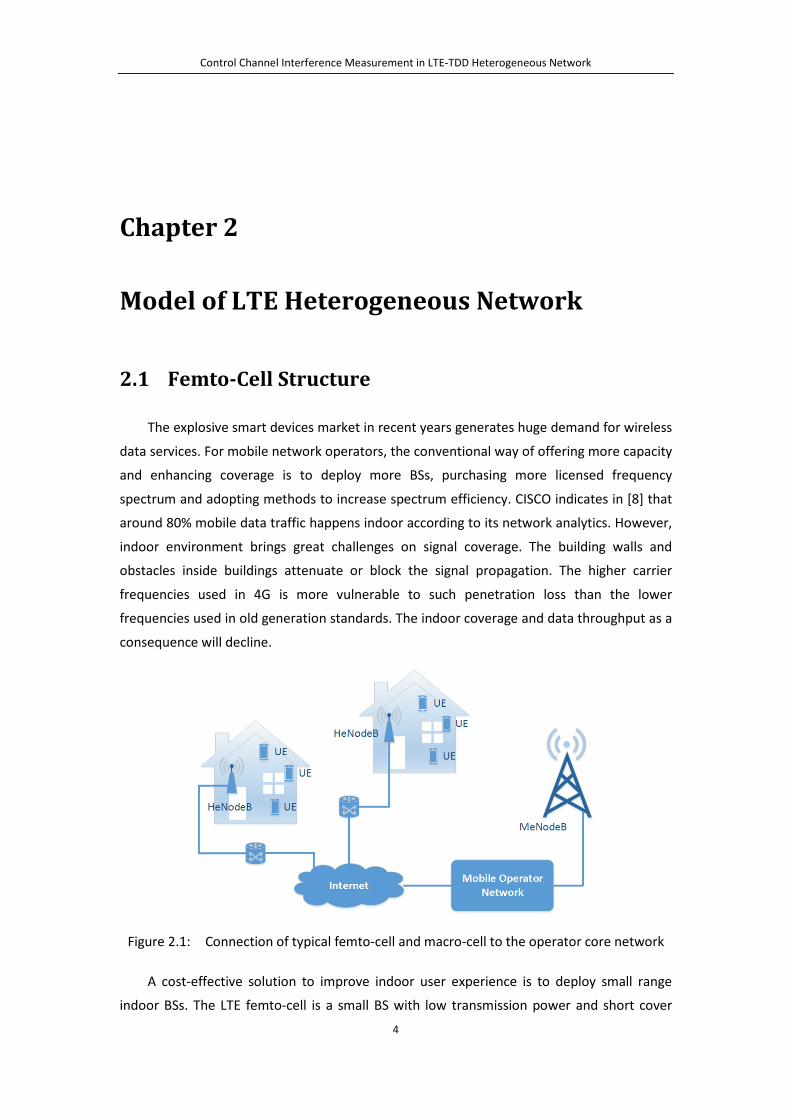
Figure 2.1: Connection of typical femto-cell and macro-cell to the operator core network
A cost-effective solution to improve indoor user experience is to deploy small range
indoor BSs. The LTE femto-cell is a small BS with low transmission power and short cover
Control Channel Interference Measurement in LTE-TDD Heterogeneous Network
5
range. Figure 2.1 displays a typical structure of femto-cell network. As a complement to
operator’s macro-cell network, femto-cell BSs are typically installed indoors. They offer
coverage enhancement, throughput escalation, traffic offloading, and even location-based
services [9]. An LTE femto-cell BS is sometimes called HeNodeB, as a shorthand for Home
eNodeB. Comparably, MeNodeB stands for regular macro-cell eNodeB. HeNodeB and
MeNodeB provide the same air interface. UE can access either HeNodeB or MeNodeB
without modification of signaling. The HeNodeB is connected to the mobile operator’s core
network through wired broadband link such as DSL or fiber.
The HeNodeBs can be configured into two modes, either Closed Subscriber Group (CSG)
or Open Subscriber Group (OSG). With CSG, each HeNodeB will maintain a list of subscribers
who can be connected to it. The 3GPP specifications define CSG options for LTE networks. In
OSG configuration, HeNodeBs are open to all UEs.
2.2 Femto-Cell and Macro-Cell Overlaid Heterogeneous
Network
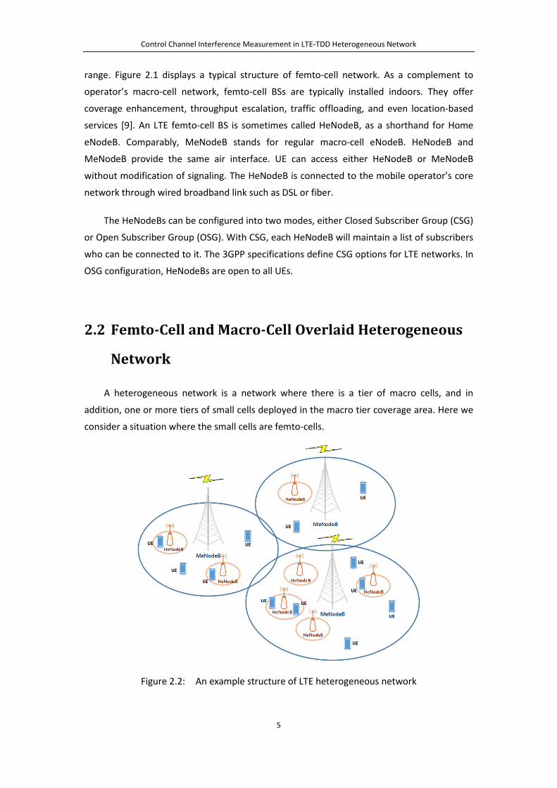
A heterogeneous network is a network where there is a tier of macro cells, and in
addition, one or more tiers of small cells deployed in the macro tier coverage area. Here we
consider a situation where the small cells are femto-cells.
Figure 2.2: An example structure of LTE heterogeneous network

Control Channel Interference Measurement in LTE-TDD Heterogeneous Network
6
A heterogeneous network example is illustrated in Figure 2.2. In such a configuration
macro-cell eNodeBs belong to a Tier-1 network and femto-cell HeNodeBs belong to a Tier-2
network. Tier-1 network provides wide area coverage and serves large quantities of
macro-cell UEs while tier-2 network serves indoor CSG users. One of the challenges that a
heterogeneous network faces is the radio resource management between femto-cells and
macro-cells. One could envision three interference management methods: exclusive
frequency allocation, overlapping frequency allocation and partially overlapping frequency
allocation, shown in Figure 2.3. Usually, radio frequency is used orthogonally, macro-cell and
femto-cell each has an exclusive part. That, however, reduces the available capacity. It is
more efficient to use whole spectrum in both macro-cell and femto-cells. If macro-cell and
femto-cell use the same frequencies, they have to deal with the generated interference. The
interference has to be maintained such that QoS target in all the cells remain within
acceptable level. The inter-cell interference management and coordination are especially
important for users at cell edge or overlapped area [10].
Figure 2.3: Radio resource share scheme between femto-cell and macro-cell
In exclusive radio resource allocation method, macro-cell and femto-cell are each
allocated with their own radio resource blocks. No cross-tier interference will happen since
femto-cell and macro-cell spectrums are not overlapped. The spectrum efficiency is achieved
by utilization of different load characteristics in macro-cell and femto-cell. The peak demand
for femto-cell is usually during the day time while macro-cell needs more resources during
users commuting i.e. rush hours. Dynamically adjustable radio resource allocation should be
achieved for increasing the spectrum efficiency. Usually, macro-cell is the primary user of
spectrum with higher privilege, while the secondary user, femto-cell will be required to

Control Channel Interference Measurement in LTE-TDD Heterogeneous Network
7
possess the capability of spectrum sensing, for identifying free resource blocks and avoiding
the overlap with primary user’s data transmission. Femto cell eNodeB can use techniques
like energy detection, waveform-based sensing, matched filtering, etc to implement
spectrum sensing. However the limitation is bad performance under low SINR environment
or increased system complexity [11][12][13][14].
In spectrum overlay approach, femto-cell eNodeB will be granted part of or whole
spectrum used by macro-cell eNodeB. Since both cells are using the same spectrum, some
type of interference coordination is required. Usually the macro-cell is the primary spectrum
user and the femto-cell eNodeB needs to adjust its transmission according to the macro-cell
eNodeB requirements. This scenario would benefit from interference cancellation algorithm,
implemented in UE or eNodeB.
2.3 Recent Research on Femto-Cell Overlaid
Heterogeneous Network
One of the major concerns of heterogeneous network is effective approaches to
mitigate femto-cell to macro-cell interference. The macro-cell UEs that are also in femto-cell
coverage area receive signals from both HeNodeB and MeNodeB. One of those could
interfere the other’s signal.
LTE subframe contains multiple OFDM (Orthogonal Frequency Division Multiplexing)
symbols. Into those symbols are multiplexed bits corresponding to control and data channels.
Control channels are located into first 1-3 OFDM symbols. In [15], a method taking
advantage of control region sparseness is introduced. In macro-cell, eNodeB needs to serve
a large quantity of UEs. As a result, a lot of control channel capacity is needed. Therefore,
more than one OFDM symbols will be configured for control channels. In femto-cell, eNodeB
usually serves very few users. The need for control signaling is much less and only fewer
OFDM symbols are sufficient for serving the requirement.
Since OFDM symbols for data region come after control region symbols, in case only
configuring single OFDM symbol as control region in femto-cell, the adjacent data region of
it will cast overlapping onto the macro-cell control region. Hence, the improvement of
macro-cell control channel performance could be achieved by avoid overlapping comes from
femto-cell data region. Femto-cell eNodeB will be enforced to utilize same size of OFDM
symbols for control region as macro-cell eNodeB does, regardless of actual payload
requirement. Femto-cell eNodeB can spread PDCCHs over the whole control region, leaving
a lot of spare UEs as shown in Figure 2.4. This method is simple, does not add any additional

Control Channel Interference Measurement in LTE-TDD Heterogeneous Network
8
signaling or require extensive computation. However, it brings capacity loss in femto-cell
since a lot of spare UEs are wasted.
Figure 2.4: Femto-cell control region sparseness for interference control
A similar mechanism is to insert Almost Blank Subframe (ABS) between normal
subframes during transmission [15][16][17]. The concept of ABS is displayed in Figure 2.5.
Femto-cell eNodeB should be muted in ABS. In these subframes it is only allowed to transmit
Cell-specific Reference Symbols (CRS), and if required, Primary Synchronization Signal (PSS),
Secondary Synchronization Signal (SSS) and Physical Broadcast Channel (PBCH). The Almost
Blank Subframe reduces the interference. Unfortunately, ABS method requires time
synchronization of radio frames between macro-cell and femto-cell and that increases
system complexity.
Figure 2.5: Using Almost Blank Subframe (ABS) to mitigate femto-cell to macro-cell
interference

Control Channel Interference Measurement in LTE-TDD Heterogeneous Network
9
Femto-cell eNodeB transmit power control [15][18] is another approach of control
channel interference deduction. Femto-cell eNodeB will adjust its transmission power
according to mean of the Reference Signal Received Power (RSRP) of the strongest
macro-cell, i.e. 𝑅𝐶𝐶𝐶������. The HeNodeB transmit power will be reduced when received 𝑅𝐶𝐶𝐶������ is
low. However, since transmission power is reduced, femto-cell transmission capacity and
coverage area will be reduced as well.
A macro-cell control channel protection algorithm that uses physical layer cell ID
manipulation is presented in [19]. In the LTE subframe, Cell-specific Reference Symbol (CRS),
Physical Control Format Indicator Channel (PCFICH) and Physical Hybrid-ARQ Indicator
Channel (PHICH) positions depend on the cell ID. By changing own cell ID to be different than
the macro-cell ID, femto-cell HeNodeB can avoid overlap of its own CRS, PCFICH and PHICH
with corresponding macro-cell channels. HeNodeB can sense macro-cell ID by detecting its
PSS and SSS [20]. However, the overlapping of PDCCH may still happen, as its position is
independent with cell ID.

Control Channel Interference Measurement in LTE-TDD Heterogeneous Network
10
Chapter 3
Downlink OFDM Transmission in LTE
OFDM, Orthogonal Frequency Division Multiplexing, is utilized in LTE Downlink radio
transmission, regarding overcoming frequency selective fading issue while providing high
spectrum efficiency. OFDM scheme will convert a group of high data rate serial signals into
low data rate parallel signals. After being mapping into resource grid, physical layer
complex-valued symbols will be transformed into OFDM symbols. A set of narrow band
subcarriers, which are mutually orthogonal, will be employed to carry these parallel signals.
Each subcarrier is corresponding to one modulated complex-valued symbol.
This chapter will briefly introduce the principle of OFDM as well as the OFDM encoder
and decoder used in LTE radio transmission.
3.1 Principle of OFDM
Figure 3.1: Spectrum of OFDM subcarriers

Control Channel Interference Measurement in LTE-TDD Heterogeneous Network
11
Unlike a conventional frequency division multiplexing (FDM) scheme, in which the
subcarriers are isolated in frequency domain, OFDM allows its subcarriers to overlap with
each other. The Figure 3.1 shows the spectrum of OFDM system. The orthogonality ensures
the peak of each subcarrier locates at the zero-crossing point of adjacent subcarriers.
Therefore, if precisely sampled at central frequency, all the subcarriers will not interfere
with each other.
The principle of a typical OFDM transmission system is described in Figure 3.2. The
OFDM encoder has 𝑁 individual modulators. A stream of serial complex-valued symbols,
(𝑎0,𝑎1, … , 𝑎𝑁−1) are sent into encoder, becoming parallel. Symbols are modulated to
different subcarriers with frequencies of 𝑓0,𝑓1, … ,𝑓𝑁−1 respectively. The frequency
interval of adjacent subcarriers is ∆𝑓 = 1 𝑇⁄ . In LTE system, ∆𝑓 = 15𝑘𝑘𝑘.
Figure 3.2: A typical OFDM modulation and demodulation system
The frequency domain OFDM encoder output signal can be expressed as:
𝑋(𝑓) = �𝑎𝑘 ∗ 𝑋𝑠(𝑓 − 𝑘 ∗ ∆𝑓)𝑁−1
𝑘=0

Control Channel Interference Measurement in LTE-TDD Heterogeneous Network
12
Within which, 𝑋𝑠(𝑓) is the subcarrier expression in frequency domain. The corresponding
time domain OFDM signal in an interval of [−𝑇/2,𝑇/2] will be:
𝑥(𝑡) =1𝑇
�𝑎𝑘 ∗ 𝑒𝑗2𝜋𝑘∆𝑓𝑓𝑁−1
𝑘=0
=1𝑇
�𝑎𝑘 ∗ 𝑒𝑗2𝜋𝑘𝑇 𝑓
𝑁−1
𝑘=0
𝑡 ∈ [−𝑇/2,𝑇/2]
Thanks to the orthogonality of subcarriers, OFDM decoder can split each symbol by
calculation integral of received subcarrier on 𝑡 ∈ [−𝑇/2,𝑇/2].
1𝑇� 𝑥𝑠1(𝑡) ∗ 𝑥𝑠2(𝑡) 𝑑𝑡𝑇2
−𝑇2
= 1𝑇� 𝑎1𝑎2 ∗ 𝑒
𝑗2𝜋𝑘1𝑇 𝑓 ∗ 𝑒−𝑗2𝜋𝑘2𝑇 𝑓𝑑𝑡
𝑇2
−𝑇2
= 1𝑇� 𝑎1𝑎2 ∗ 𝑒
𝑗2𝜋(𝑘1−𝑘2)𝑇 𝑓𝑑𝑡
𝑇2
−𝑇2
= �0 𝑘1 ≠ 𝑘2𝑎1𝑎2 𝑘1 = 𝑘2
Hence, for a complex-valued symbol 𝑎𝑘, it can be recovered as below:
� 𝑥�𝑠(𝑡) 𝑑𝑡 = 𝑇2
−𝑇2
� 1𝑇
�𝑎�𝑘 ∗ 𝑒𝑗2𝜋𝑘𝑇 𝑓
𝑁−1
𝑘=0
∗ 𝑒−𝑗2𝜋𝑠𝑇 𝑓𝑑𝑡
𝑇2
−𝑇2
= 1𝑇� � 𝑎�𝑘 ∗ 𝑒
𝑗2𝜋𝑘𝑇 𝑓
𝑘≠𝑠
∗ 𝑒−𝑗2𝜋𝑠𝑇 𝑓𝑑𝑡 +
𝑇2
−𝑇2
1𝑇� 𝑎�𝑘𝑑𝑡 𝑇2
−𝑇2
= 0 + 𝑎�𝑘 = 𝑎�𝑘
In continuous signal system transmitter side, it needs to generate a number of 𝑁
different subcarriers with ∆𝑓 frequency. On the receiver side, it also needs 𝑁 different
subcarriers and doing 𝑁 times integral in order to recover out all the signals.
3.2 OFDM Encoding and Decoding in LTE Unlike continuous signal processing principle showed above, the real LTE system use
time discrete OFDM signals. N-Point IFFT (Inverse Fast Fourier Transform) is used as OFDM
encoder and N-Point FFT (Fast Fourier Transform) is used as OFDM decoder, explained in
Figure 3.3 and Figure 3.4.

Control Channel Interference Measurement in LTE-TDD Heterogeneous Network
13
Figure 3.3: OFDM encoder with cyclic prefix
The transmitter does not need to modulate each route signal individually. The IFFT
module works in frequency domain, directly calculates out the time domain summation of
𝑁 routes orthogonal signal. On the other hand, the receiver no longer needs to do integral
as FFT will directly recover back the frequency domain signal of each orthogonal route.
Figure 3.4: OFDM decoder with cyclic prefix
𝑀 complex-valued symbols are sent to the encoder. Several zeroes need to be inserted
after serial-to-parallel transforming, for fulfilling the IFFT size 𝑁.

Control Channel Interference Measurement in LTE-TDD Heterogeneous Network
14
Figure 3.5: Cyclic Prefix concept
In order to provide robustness against Inter Symbol Interference caused by multipath
distortion, Cyclic Prefix (CP) is also introduced. A cyclic prefix insertion module is deployed
after N-Point IFFT. It works in time domain, copying last section of OFDM symbol into its
beginning, as displayed in Figure 3.5. Correspondingly, the cyclic prefix needs removal at
receiver side before conducting FFT. As long as the delay of the reception symbol is not
bigger than the time length of CP, the receiver can correctly recover the symbol.
Control Channel Interference Measurement in LTE-TDD Heterogeneous Network
15
Chapter 4
LTE Physical Layer Concepts
In this section, we describe LTE physical layer structure, frame definition and basic
resource units. We also discuss the advantages and disadvantages between LTE-TDD mode
and LTE-FDD mode as well as why we are interested in choosing TDD mode in our system
implementation.
4.1 LTE Physical Frame Structure
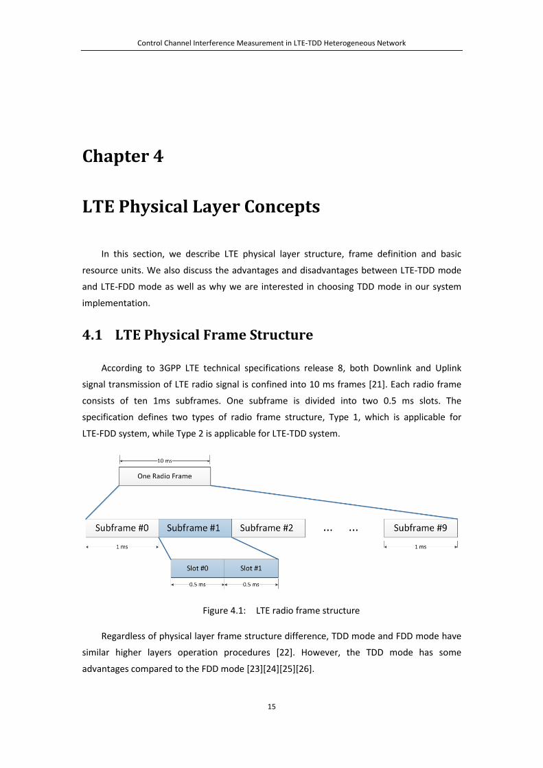
According to 3GPP LTE technical specifications release 8, both Downlink and Uplink
signal transmission of LTE radio signal is confined into 10 ms frames [21]. Each radio frame
consists of ten 1ms subframes. One subframe is divided into two 0.5 ms slots. The
specification defines two types of radio frame structure, Type 1, which is applicable for
LTE-FDD system, while Type 2 is applicable for LTE-TDD system.
Figure 4.1: LTE radio frame structure
Regardless of physical layer frame structure difference, TDD mode and FDD mode have
similar higher layers operation procedures [22]. However, the TDD mode has some
advantages compared to the FDD mode [23][24][25][26].
Control Channel Interference Measurement in LTE-TDD Heterogeneous Network
16
Since Uplink (UL) and Downlink (DL) transmission are duplexed in the same frequency,
TDD mode does not require paired spectrum for UL and DL individually. The expense of
purchasing the licensed TDD band is usually lower compared to the FDD band. Besides,
implementation of TDD devices is also less expensive consider as they require less expensive
RF components (e.g. no RF frequency duplex filter is needed). In addition, TDD mode is more
suitable for MIMO implementation. The quality of MIMO highly depends on the accurate
channel estimation. In TDD mode, the measured channel characteristics of UL can be used
for DL as well after precise calibration. The implementation of MIMO in FDD mode is
comparably more difficult.
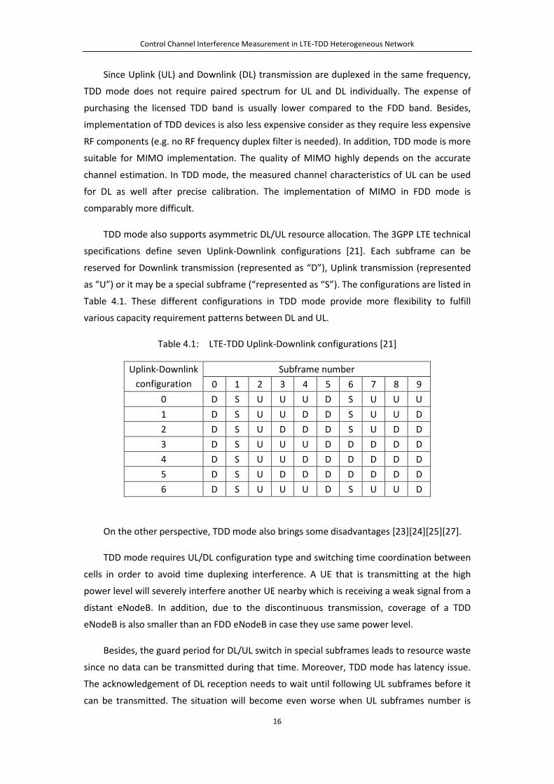
TDD mode also supports asymmetric DL/UL resource allocation. The 3GPP LTE technical
specifications define seven Uplink-Downlink configurations [21]. Each subframe can be
reserved for Downlink transmission (represented as “D”), Uplink transmission (represented
as “U”) or it may be a special subframe (“represented as “S”). The configurations are listed in
Table 4.1. These different configurations in TDD mode provide more flexibility to fulfill
various capacity requirement patterns between DL and UL.
Table 4.1: LTE-TDD Uplink-Downlink configurations [21]
Uplink-Downlink configuration
Subframe number 0 1 2 3 4 5 6 7 8 9
0 D S U U U D S U U U 1 D S U U D D S U U D 2 D S U D D D S U D D 3 D S U U U D D D D D 4 D S U U D D D D D D 5 D S U D D D D D D D 6 D S U U U D S U U D
On the other perspective, TDD mode also brings some disadvantages [23][24][25][27].
TDD mode requires UL/DL configuration type and switching time coordination between
cells in order to avoid time duplexing interference. A UE that is transmitting at the high
power level will severely interfere another UE nearby which is receiving a weak signal from a
distant eNodeB. In addition, due to the discontinuous transmission, coverage of a TDD
eNodeB is also smaller than an FDD eNodeB in case they use same power level.
Besides, the guard period for DL/UL switch in special subframes leads to resource waste
since no data can be transmitted during that time. Moreover, TDD mode has latency issue.
The acknowledgement of DL reception needs to wait until following UL subframes before it
can be transmitted. The situation will become even worse when UL subframes number is
Control Channel Interference Measurement in LTE-TDD Heterogeneous Network
17
very small in asymmetric UL/DL configurations, i.e. configuration 5 in which only one UL
subframe exists per every 8 DL subframes.
In the real commercial environment, operators usually need to make a compromise and
consider the above characteristics when choosing their LTE system duplex mode.
However, when it comes to our heterogeneous network scenario that contains indoor
small cells, some features make LTE-TDD mode more interested to us. The small size of
indoor femto-cell is not sensitive to the TDD coverage issue. The low cost of TDD eNodeB
will also be attractive to the users. TDD’s advance on MIMO deploying benefits the indoor
high throughput requirement. Moreover, some shortages of TDD mode become less harmful
[23]. The time duplexing interference between indoor femto-cell and ourdoor macro-cell can
be mitigated by building wall isolation.
In this thesis we will use LTE-TDD standard to implement our system and conduct the
measurement. Hence, in the below introduction of LTE physical layer concept we will discuss
only Type 2 LTE-TDD structure and denote it as the default.
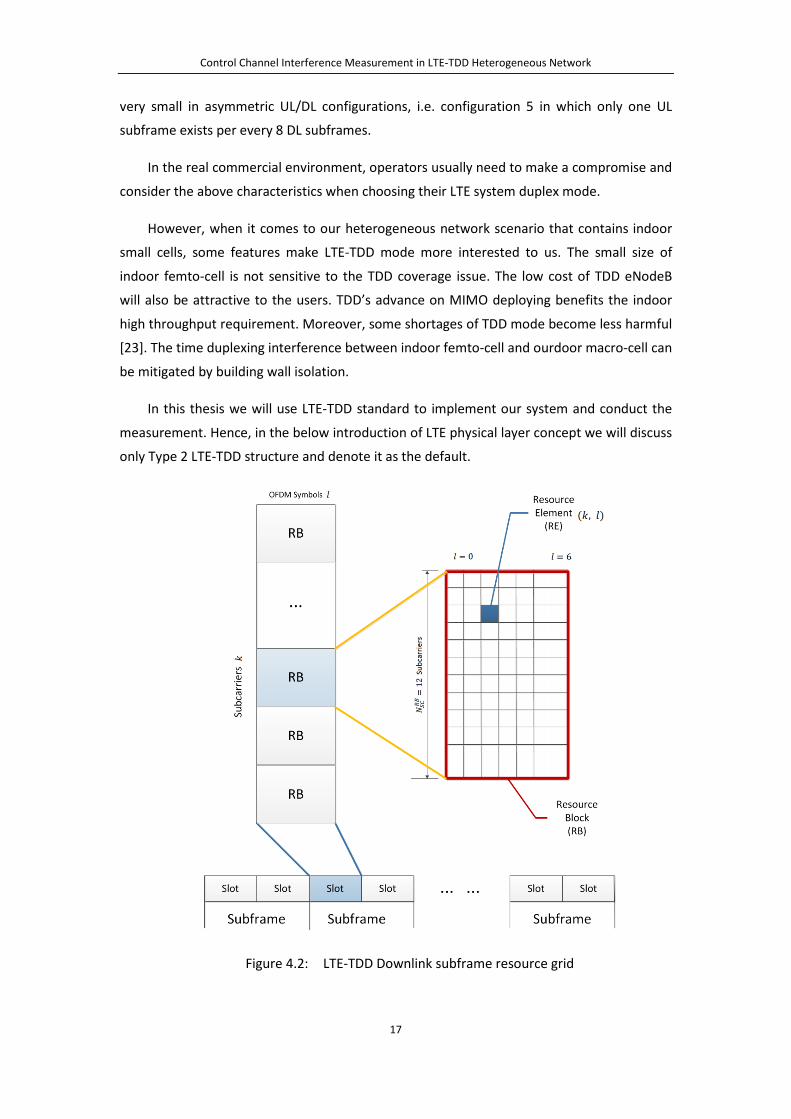
Figure 4.2: LTE-TDD Downlink subframe resource grid

Control Channel Interference Measurement in LTE-TDD Heterogeneous Network
18
The transmitted radio signal within each slot is mapped to time-frequency resource grid,
shown in Figure 4.2. The resource grid contains OFDM symbols in DL, or SC-FDMA symbols in
UL.
The basic time-frequency unit in the grid is call Resource Element, or RE. One 0.5 ms
slot contains seven symbols. One RE is one subcarrier by one symbol. The distance between
adjacent subcarriers is 15 kHz, i.e. frequency distance between two consecutive REs is 15
kHz. Each RE in the grid can be identified as index pair (𝑘, 𝑙), within which 𝑘 is frequency
domain indices and 𝑙 is time domain indices.
In order to describe the mapping of modulated physical signal symbols into the
resource elements, REs are grouped into resource blocks (RB). One resource block contains
twelve consecutive subcarriers in frequency domain, and seven consecutive symbols in a slot,
respectively. RB is used as a unit to describe transmission bandwidth of DL and UL. For both
DL and UL, the current specification indicates the smallest transmission bandwidth to be
6RBs, occupying 1.08 MHz in frequency. While the largest to be 100RBs, occupying 18 MHz
in frequency [28].
Figure 4.3: Relation between LTE channel bandwidth and transmission bandwidth.
It should be reminded that transmission bandwidth is different for different channel
bandwidths. As displayed in Figure 4.3, the transmission bandwidth is usually smaller than
the channel bandwidth. The idea is to providing the guard band between the transmissions
of different operators, protecting them from adjacent channel interference.
There are six different transmission bandwidth configurations defined in LTE, listed in
Table 4.2. In the rest of this thesis, DL or UL bandwidth usually refers to transmission
bandwidth.

Control Channel Interference Measurement in LTE-TDD Heterogeneous Network
19
Table 4.2: LTE transmission bandwidth configurations
Channel BW (MHz)
Transmission BW (RB)
Occupied BW (MHz)
1.4 6 1.08 3 15 2.7 5 25 4.5
10 50 9 15 75 13.5 20 100 18
4.2 REG and CCE
The resource grid will be loaded with physical layer symbols, including reference
symbols, synchronization symbols, control channel symbols and shared channel symbols.
Depending on the usage, the LTE-TDD resource grid can be divided into two regions: control
region and data region.
Figure 4.4: Control region and data region of a subframe
The control region, used for carrying control signaling, includes Physical Control Format
Indicator Channel (PCFICH), Physical Hybrid-ARQ Indicator Channel (PHICH) and Physical
Downlink Control Channel (PDCCH).
The data region is used for carrying data signal. It contains the Primary Synchronization
Signal (PSS), Secondary Synchronization Signal (SSS), Physical Downlink Shared Channel
(PDSCH), Physical Broadcast Channel (PBCH), etc. Cell-specific reference symbols are
contained both in the control region and the date region.

Control Channel Interference Measurement in LTE-TDD Heterogeneous Network
20
In an LTE DL subframe, the control region usually occupies the first 1 to 3 OFDM
symbols (for 1.44MHz channel bandwidth, it is 2 to 4 OFDM symbols, due to the limited REs
number within each symbol). The exact symbols number configured depends on system
bandwidth and the cell load. The rest OFDM symbols are occupied by data region.
Figure 4.4 illustrates a DL subframe where control region consists of three symbols. This
figure is only for normal DL subframe. It does not consider Multimedia Broadcast Single
Frequency Network (MBSFN) subframe. MBSFN subframe is used for providing Multimedia
Broadcasting service. It uses a different structure than normal DL subframe. The number and
locations of MBSFN depend on the network configuration.
In order to schedule the control channel resources effectively, 3GPP LTE specification
defines two basic resource units, Resource Element Group (REG) and Control Channel
Element (CCE), dedicatedly for control region usage.
REG represents four consecutive unused resource elements in one OFDM symbol. It
could be four physically consecutive REs, or in another situation that usually happens in the
first OFDM symbol of a subframe, six REs, within which two REs are used by cell-specific
reference symbols. Few REGs are used for PCFICH and PHICH allocation. These two channels
carry a relatively low amount of data. Compared to them, PDCCH size can be bigger. CCE,
which consists of 9 unused REGs, is used as the basic unit for allocating PDCCH data.

Control Channel Interference Measurement in LTE-TDD Heterogeneous Network
21
Chapter 5
LTE DL Physical Channel Structure
This section focuses on the structure of the major DL physical layer control channels in
LTE-TDD standard, including PCFICH, PHICH and PDCCH, as well as their corresponding
algorithms of encoding and mapping.
5.1 PCFICH
PCFICH carries Control Format Indicator (CFI). The value of CFI ranges from 1 to 4,
informs UE the size of the control region. The relation between CFI values and control region
size is illustrated in Table 5.1. When Downlink bandwidth 𝑁𝐶𝑅𝐷𝐷 > 10, control region symbols
number equals CFI value. On the other hand, when Downlink bandwidth 𝑁𝐶𝑅𝐷𝐷 ≤ 10, control
region symbols number equals CFI + 1. A special case is in subframe 1 and subframe 6, which
have PSS symbols on 3rd OFDM symbol. In these subframes, the number of OFDM symbols
scheduled for control region cannot surpass two.
Table 5.1: Number of OFDM symbols for control region
DL Bandwidth CFI Value
𝑁𝐶𝑅𝐷𝐷 > 10 𝑁𝐶𝑅𝐷𝐷 ≤ 10
Subframe 1 and 6 1 1 2 2 2 N/A
Other subframes 1 1 2 2 2 3 3 3 4
CFI value is protected by simple repetition coding. The 32-bit codewords are shown in
Table 5.2. The all-zero codeword of CFI=4 is reserved and currently not used.

Control Channel Interference Measurement in LTE-TDD Heterogeneous Network
22
Table 5.2: CFI code words [21]
CFI CFI codeword < 𝑏0,𝑏1, … , 𝑏31 > 1 < 0,1,1,0,1,1,0,1,1,0,1,1,0,1,1,0,1,1,0,1,1,0,1,1,0,1,1,0,1,1,0,1 > 2 < 1,0,1,1,0,1,1,0,1,1,0,1,1,0,1,1,0,1,1,0,1,1,0,1,1,0,1,1,0,1,1,0 > 3 < 1,1,0,1,1,0,1,1,0,1,1,0,1,1,0,1,1,0,1,1,0,1,1,0,1,1,0,1,1,0,1,1 > 4 reserved, all-0
The same CFI codewords are used in all the cells. The codewords in different cells are
protected by cell-specific scrambling sequences [21]. The scrambled 32-bit codewords will
be modulated using QPSK scheme, becomes 16 complex-valued symbols. In this thesis, layer
mapping and precoding techniques will not be considered. The 16 complex-valued symbols
are directly mapped to first OFDM symbol of each DL subframe. The mapping is done by
grouping the 16 symbols into four symbol groups, expressed as 𝑘(𝑔)(0), 𝑘(𝑔)(1), 𝑘(𝑔)(2)
and 𝑘(𝑔)(3), each contains four symbols. In order to obtain frequency diversity gain, four groups are mapped into four REGs. These REGs are uniformly distributed over whole
transmission bandwidth, based on the rules listed below:
𝑘(𝑔)(𝑚) is mapped to resource element group represented by index 𝑘𝑖,
𝑘𝑖 = 𝑘� + �𝑚 ∗ 𝑁𝐶𝑅𝐷𝐷 2⁄ � ∙ 𝑁𝑠𝑠𝐶𝑅 2 𝑚 = 0, 1, 2, 3⁄
of which, 𝑘� = (𝑁𝑠𝑠𝐶𝑅 2⁄ ) ∙ (𝑁𝐼𝐷𝑠𝑐𝑐𝑐 𝑚𝑁𝑑 2𝑁𝐶𝑅𝐷𝐷). After calculation, 𝑘𝑖 will modulo 𝑁𝐶𝑅𝐷𝐷 ∗ 𝑁𝑠𝑠𝐶𝑅.
𝑁𝐼𝐷𝑠𝑐𝑐𝑐 is physical layer cell identity number.
Figure 5.1 summarizes the PCFICH coding and mapping procedures.
Figure 5.1: PCFICH processing procedures

Control Channel Interference Measurement in LTE-TDD Heterogeneous Network
23
5.2 PHICH
Physical Hybrid-ARQ Indicator Channel (PHICH), carries feed-back Hybrid ARQ
information. After Physical Uplink Shared Channel (PUSCH) data transmission, UE waits for
ACK/NACK feedback from eNodeB. This feedback is coded in PHICH. PHICH is carried in first
one to three OFDM symbols in a subframe. Several PHICHs can be multiplexed into a same
set of REs. These PHICHs form a PHICH-group. Several PHICH groups can exist in one
subframe. The PHICH multiplexing is achieved by using orthogonal sequence.
Two parameters, PHICH-Duration and PHICH-Resource index pair, will define the PHICHs
distribution and help to identify each specific one.
PHICH-Duration indicates the OFDM symbols number used by PHICHs. According to
Table 6.9.3-1 in [21], in normal situation, PHICHs only occupy the first OFDM symbol. In
order to provide extra time diversity gain, extended PHICH duration will be used. It will need
2 or 3 symbols regarding the subframe type. In this thesis, only the normal duration is used.
PHICH-Resource index pair is defined as (𝑛𝑃𝑃𝐼𝐶𝑃𝑔𝑔𝑔𝑔𝑔 , 𝑛𝑃𝑃𝐼𝐶𝑃
𝑠𝑐𝑠 ). 𝑛𝑃𝑃𝐼𝐶𝑃𝑔𝑔𝑔𝑔𝑔
is the PHICH group
index, which is used to distinguish different PHICH groups. 𝑛𝑃𝑃𝐼𝐶𝑃𝑠𝑐𝑠 is the orthogonal
sequence index, is used to distinguish PHICHs within a same PHICH group.
According to PHICH specification in [21], maximum PHICH group number is defined by
𝑚𝑖 ∗ 𝑁𝑃𝑃𝐼𝐶𝑃𝑔𝑔𝑔𝑔𝑔.
𝑛𝑃𝑃𝐼𝐶𝑃𝑔𝑔𝑔𝑔𝑔 = �
�𝑁𝑔 (𝑁𝐶𝑅𝐷𝐷/ 8)� 𝑓𝑁𝑓 𝑛𝑁𝑓𝑚𝑎𝑙 𝑐𝑐𝑐𝑙𝑚𝑐 𝑝𝑓𝑒𝑓𝑚𝑥2 ∙ �𝑁𝑔 (𝑁𝐶𝑅𝐷𝐷/ 8)� 𝑓𝑁𝑓 𝑒𝑥𝑡𝑒𝑛𝑑𝑒𝑑 𝑐𝑐𝑐𝑙𝑚𝑐 𝑝𝑓𝑒𝑓𝑚𝑥
𝑁𝑔 is a parameter provided by the upper layer, which can be 1/6, 1/2, 1 or 2. Factor
𝑚𝑖 depends on the subframe number and the Uplink-Downlink configuration type, which is
shown in Table 5.3.
PHICH and PDCCH share control region. The bigger 𝑁𝑔 can support a larger quantity
of HARQ feedbacks, however, that benefit comes at the expense of PDCCH channel capacity.
The situation is especially severe when control region size is small, i.e. CFI value is configured
to be small and transmission bandwidth is limited.

Control Channel Interference Measurement in LTE-TDD Heterogeneous Network
24
Table 5.3: Factor 𝑚𝑖 for LTE-TDD configurations [21]
Uplink-Downlink configuration
Subframe number 0 1 2 3 4 5 6 7 8 9
0 2 1 - - - 2 1 - - - 1 0 1 - - 1 0 1 - - 1 2 0 0 - 1 0 0 0 - 1 0 3 1 0 - - - 0 0 0 1 1 4 0 0 - - 0 0 0 0 1 1 5 0 0 - 0 0 0 0 0 1 0 6 1 1 - - - 1 1 - - 1
Under normal cyclic prefix, a PHICH group can support up to 8 PHICHs multiplexing used,
while under extended cyclic prefix, it can only support up to 4 PHICHs. Table 5.4 lists the
orthogonal sequences used.
Table 5.4: Orthogonal sequence for PHICHs in the same group [21]
Sequence index 𝑛𝑃𝑃𝐼𝐶𝑃𝑠𝑐𝑠
Orthogonal sequence
Normal cyclic prefix Extended cyclic prefix
0 [+1 + 1 + 1 + 1] [+1 + 1] 1 [+1 − 1 + 1 − 1] [+1 − 1] 2 [+1 + 1 − 1 − 1] [+𝑗 + 𝑗 ] 3 [+1 − 1 − 1 + 1] [+𝑗 − 𝑗 ] 4 [+𝑗 + 𝑗 + 𝑗 + 𝑗] - 5 [+𝑗 − 𝑗 + 𝑗 − 𝑗] - 6 [+𝑗 + 𝑗 − 𝑗 − 𝑗] - 7 [+𝑗 − 𝑗 − 𝑗 + 𝑗] -
The actual HARQ information a PHICH carries is only one bit, either 1 (positive
acknowledgement) or 0 (negative acknowledgement). The one-bit ACK/NACK will be
repeated three times. The repeated sequence is modulated into 3 complex-valued BPSK
symbols. All of them are multiplied by one orthogonal sequence defined in Table 5.4 for
frequency spread and then scrambled with a cell-specific scrambling sequence, according to
the equations introduced in Chapter 6.9.1 of [21].
For normal cyclic prefix (CP) scenario, spreading factor is 4. A 4-symbol orthogonal
sequence is multiplied to the 3-symbol BPSK signal. Thus, a 12-symbol length data will be
generated after these procedures.

Control Channel Interference Measurement in LTE-TDD Heterogeneous Network
25
For extended CP scenario, spreading factor is 2. A 2-symbol orthogonal sequence is
used to multiply the 3-symbol BPSK signal. According to equations in Chapter 6.9.2 of [21],
adding 0 into the 6-symbol length product will expend it to 12-symbol length, which is same
as normal cyclic prefix situation.
Multiple PHICHs within one PHICH group will use the same 12 REs, their corresponding
symbols will be added together and mapped onto 3 free REGs that have not been used by
PCFICH. The REGs positions in each PHICH group depend on PHICH-Duration and
PHICH-Resource parameters configurations. The algorithm for calculating positions is
defined in Chapter 6.9.3 of [21].
Extended CP has less PHICHs multiplexed into same REGs, in order to give each one
more protection. To settle same number of PHICHs, extended CP needs to occupy more
resource compared to normal CP.
Figure 5.2: PHICH processing procedures (Normal Cyclic Prefix example)
In our tests the PHICH group number is set to 1 and we use normal cyclic prefix. Hence,
all together only 3 REGs for all PHICHs (one group) will exist in first OFDM symbol in the DL
subframe. The REGs’ frequency domain position 𝑛𝚤� then can be derived as below:
𝑛𝚤� = �𝑁𝐼𝐷𝑠𝑐𝑐𝑐 + ⌊𝑚 ∗ 𝑛1′ 3⁄ ⌋� 𝑚𝑁𝑑 𝑛1′ 𝑚 = 0, 1, 2

Control Channel Interference Measurement in LTE-TDD Heterogeneous Network
26
𝑛1′ is the free REGs number in first OFDM symbol that have not been occupied by PCFICH.
Three REGs are uniformly distributed on the first OFDM symbol, with interval of about 1/3
DL bandwidth. Figure 5.2 describes the PHICHs coding, multiplexing and mapping
procedures.
5.3 PDCCH
Physical Downlink Control Channel (PDCCH) is allocated into first 1 to 3 OFDM symbols
of the corresponding subframe. The number of symbols used is defined by CFI values carried
in PCFICH channel. Their relation has been introduced in Chapter 5.1.
PDCCH is used by eNodeB for carrying Downlink control signaling, also known as DCI
message. The DCI messages will contain the Downlink resource scheduling information for
the current subframe, Uplink resource assignment for the UE, Uplink Transmit Power Control
(TPC) command, etc. The DCI bits are protected by 16-bit Cyclic Redundancy Check (CRC)
code and tail biting convolutional code. After convolutional encoding, the bits are rate
matched and modulated into QPSK symbols. The complex-valued symbols are mapped into
the physical resource grid of the subframe. The whole procedure from DCI bits to PDCCH
symbol mapping is displayed in Figure 5.3 below:
Figure 5.3: PDCCH physical layer procedures
LTE supports four different PDCCH formats, defined in Chapter 6.8.1 of [21]. The
formats are listed in Table 5.5 below. Each format will double the size of previous format,
containing more cyclic redundancy. The largest format gives the best protection against
interference.

Control Channel Interference Measurement in LTE-TDD Heterogeneous Network
27
Table 5.5: Supported PDCCH formats
PDCCH format
CCEs number
REGs number
REs number
Bits can load
0 1 9 36 72 1 2 18 72 144 2 4 36 144 288 3 8 72 288 576
5.3.1 DCI
As introduced above, DCI is the PDCCH payload content. 3GPP LTE specification Release
-8 defines various DCI formats [29] for control signaling in different usage area, summarized
in Table 5.6:
Table 5.6: 3GPP LTE release-8 supported DCI format and corresponding usage area
DCI format DCI format usage area
0 Physical Uplink Shared Channel (PUSCH)
scheduling
1 PDSCH scheduling in Single Input Multiple
Output (SIMO) scenario
1A PDSCH compact scheduling in SIMO scenario
and random access procedure
2B PDSCH compact scheduling in Multiple Input
Multiple Output (MIMO) scenario
1C PDSCH very compact scheduling
1D PDSCH compact scheduling with power offset
and precoding
2 PDSCH scheduling with closed-loop MIMO
2A PDSCH scheduling with open-loop MIMO
3 sending TPC commands for Physical Uplink
Control Channel (PUCCH) and PUSCH
The number of DIC bits is format specific. However even identical formats could have
different numbers of bits regarding different transmission bandwidths. Within one subframe,
Control Channel Interference Measurement in LTE-TDD Heterogeneous Network
28
eNodeB may send several DCIs for different UEs at the same time. Also, one subframe can
contain multiple different types of DCI that are all sent to one UE.
In this thesis, we use DCI format 0 only. The bits of it, [𝑎0,𝑎1, … ,𝑎𝐴−1], consist of
control signaling features which are coded according to Chapter 5.3.3.1.1 in [29]:
1 bit: Differentiation of format 0 and format 1A. Value of 0 will inform UE the received
DCI is format 0, or oppositely it is format 1A in case value of 1 is detected.
1 bit: Used as hopping flag.
�𝑙𝑁𝑔2 (𝑁𝐶𝑅𝑈𝐷(𝑁𝐶𝑅𝑈𝐷 + 1)/ 2)� bits: Used for resource block assignment and hopping
resource allocation.
5 bits: Indicating the modulation used and type of redundancy.
1 bit: Indicating whether it is new data.
2 bits: Transmission power control for PUSCH.
3 bits: Cyclic shift for Demodulation Reference Signal (DMRS) used in PUSCH.
2 bits: UL index if using TDD Downlink-Uplink configuration 0. Or Downlink assignment
index for other TDD Downlink-Uplink configurations.
1 bit: Channel Quality Indication (CQI) request.
During the test we use 3MHz (15 RB) DL and UL bandwidth, all together 23 bits will be
contained in a Format 0 DCI.
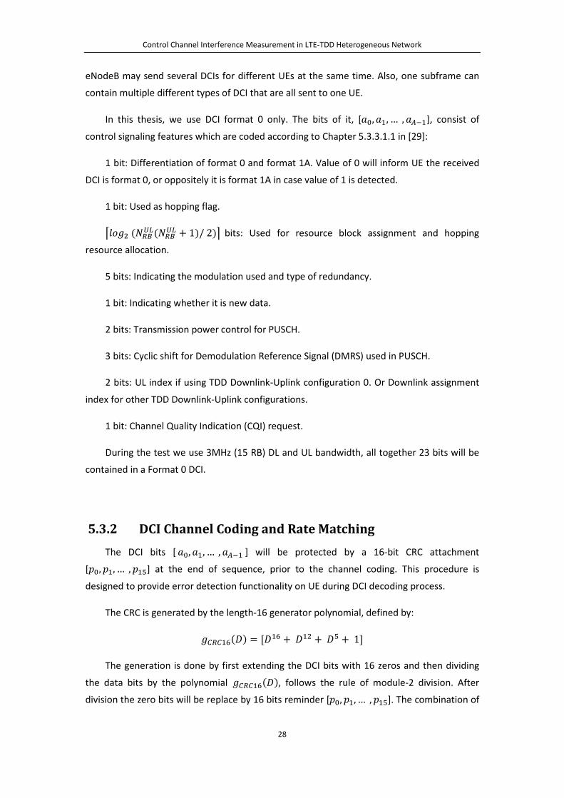
5.3.2 DCI Channel Coding and Rate Matching The DCI bits [ 𝑎0,𝑎1, … ,𝑎𝐴−1 ] will be protected by a 16-bit CRC attachment
[𝑝0,𝑝1, … ,𝑝15] at the end of sequence, prior to the channel coding. This procedure is
designed to provide error detection functionality on UE during DCI decoding process.
The CRC is generated by the length-16 generator polynomial, defined by:
𝑔𝐶𝐶𝐶16(𝐷) = [𝐷16 + 𝐷12 + 𝐷5 + 1]
The generation is done by first extending the DCI bits with 16 zeros and then dividing
the data bits by the polynomial 𝑔𝐶𝐶𝐶16(𝐷), follows the rule of module-2 division. After
division the zero bits will be replace by 16 bits reminder [𝑝0,𝑝1, … ,𝑝15]. The combination of

Control Channel Interference Measurement in LTE-TDD Heterogeneous Network
29
original data bits and the 16-bit reminder, [𝑏0,𝑏1, … , 𝑏𝐴+15 ], will be channel coded
afterwards.
At the receiver side the UE divides the received data bits [𝑏0′ ,𝑏1′ , … , 𝑏𝐴+15′ ] by the same
polynomial 𝑔𝐶𝐶𝐶16(𝐷). The correct received bits sequence will yield to a remainder
identical to 0. Otherwise, even 1 bit error in reception will yield to an un-zero remainder,
indicating the failure of CRC check.
By using CRC check, UE can distinguish whether DCI bits have correctly decoded and
whether the retransmission of corresponding PDCCH is required. In order to enable UE to
identify its own PDCCH from others, CRC bits will be scrambled with a 16-bit UE RNTI
sequence ⟨𝑥𝑔𝑟𝑓𝑖,0,𝑥𝑔𝑟𝑓𝑖,1, … , 𝑥𝑔𝑟𝑓𝑖,15⟩, according to equations below [29]. It leads to a new
sequence [𝑐0, 𝑐1, … , 𝑐𝐴+15]. RNTI stands for Radio Network Temporary Identifier number.
𝑐𝑘 = �𝑏𝑘 ( 𝑘 = 0, 1, 2, … ,𝐴 − 1)
�𝑏𝑘 + 𝑥𝑔𝑟𝑓𝑖,𝑘−𝐴�𝑚𝑁𝑑 2 ( 𝑘 = 𝐴,𝐴 + 1,𝐴 + 2, … ,𝐴 + 15)
In case MIMO is also configured on UE, an additional scrambling function will be
deployed. UE antenna selection mask ⟨𝑥𝐴𝐶,0,𝑥𝐴𝐶,1, … , 𝑥𝐴𝐶,15⟩ is used to distinguish different
antenna ports.
𝑐𝑘 = �𝑏𝑘 ( 𝑘 = 0, 1, 2, … ,𝐴 − 1)
�𝑏𝑘 + 𝑥𝑔𝑟𝑓𝑖,𝑘−𝐴 + 𝑥𝐴𝐶,𝑘−𝐴�𝑚𝑁𝑑 2 ( 𝑘 = 𝐴,𝐴 + 1,𝐴 + 2, … ,𝐴 + 15)
⟨𝑥𝐴𝐶,0, 𝑥𝐴𝐶,1, … , 𝑥𝐴𝐶,15⟩ = �⟨0, 0, 0, 0, 0, 0, 0, 0, 0, 0, 0, 0, 0, 0, 0, 0⟩ 𝑈𝐸 𝑎𝑛𝑡𝑒𝑛𝑛𝑎 𝑝𝑁𝑓𝑡0⟨0, 0, 0, 0, 0, 0, 0, 0, 0, 0, 0, 0, 0, 0, 0, 1⟩ 𝑈𝐸 𝑎𝑛𝑡𝑒𝑛𝑛𝑎 𝑝𝑁𝑓𝑡1
During reception procedure, UE can identify whether the PDCCH in decoding attempt is
for itself by conducting CRC checking on the descrambled bits sequence.
Figure 5.4: 1/3 Code Rate Tail Biting Convolutional Encoder
The CRC extended DCI bits are channel coded with tail biting convolutional code. The
LTE specification uses 1/3 code rate with constraint length 7. The encoder configuration is
illustrated in Figure 5.4.
Control Channel Interference Measurement in LTE-TDD Heterogeneous Network
30
At the beginning, the 6-bit shift register will be initialized with the last 6 bits of input
sequence, here means [𝑐𝐴+10, 𝑐𝐴+11, … , 𝑐𝐴+15]. The encoder will generate three output
streams, 𝑑𝑘(0), 𝑑𝑘
(1) and 𝑑𝑘(2). Within each step 𝑘, output 𝑑𝑘
(𝑖) is calculated by summing
up input bit 𝑐𝑘 with the bits in the register as Figure 5.4 shown. Afterwards, register will
shift right one bit, and insert the 𝑐𝑘 into the first left bit of register. The three output
streams have the same size 𝐴 + 16. They will be collected one after the other and
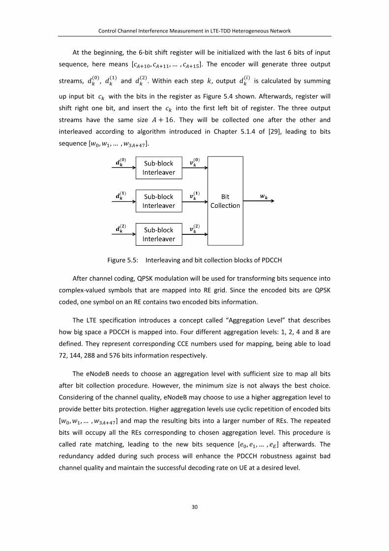
interleaved according to algorithm introduced in Chapter 5.1.4 of [29], leading to bits
sequence [𝑤0,𝑤1, … ,𝑤3𝐴+47].
Figure 5.5: Interleaving and bit collection blocks of PDCCH
After channel coding, QPSK modulation will be used for transforming bits sequence into
complex-valued symbols that are mapped into RE grid. Since the encoded bits are QPSK
coded, one symbol on an RE contains two encoded bits information.
The LTE specification introduces a concept called “Aggregation Level” that describes
how big space a PDCCH is mapped into. Four different aggregation levels: 1, 2, 4 and 8 are
defined. They represent corresponding CCE numbers used for mapping, being able to load
72, 144, 288 and 576 bits information respectively.
The eNodeB needs to choose an aggregation level with sufficient size to map all bits
after bit collection procedure. However, the minimum size is not always the best choice.
Considering of the channel quality, eNodeB may choose to use a higher aggregation level to
provide better bits protection. Higher aggregation levels use cyclic repetition of encoded bits
[𝑤0,𝑤1, … ,𝑤3𝐴+47] and map the resulting bits into a larger number of REs. The repeated
bits will occupy all the REs corresponding to chosen aggregation level. This procedure is
called rate matching, leading to the new bits sequence [𝑒0, 𝑒1, … , 𝑒𝐸] afterwards. The
redundancy added during such process will enhance the PDCCH robustness against bad
channel quality and maintain the successful decoding rate on UE at a desired level.

Control Channel Interference Measurement in LTE-TDD Heterogeneous Network
31
5.3.3 PDCCH Symbols Mapping
The bit sequence [𝑒0, 𝑒1, … , 𝑒𝐸] will be QPSK modulated. The encoded complex-valued
PDCCH symbols are mapped onto CCEs arranged for them. Unlike PCFICH and PHICH
mapping that can calculate scheduled REGs’ positions directly, PDCCH symbols mapping is
based on the availability of REGs in a given subframe. Before conducting the actual mapping,
the eNodeB is required to count the total number of free REGs left in control region. These
are REGs that have not been occupied by PCFICH or PHICH. Such free REGs will be numbered
from 0 to 𝑁𝐶𝐸𝑅 − 1.
The REGs are indexed by a specific algorithm in Chapter 6.5.8 of [21]. The pseudo code
below describes the indexing procedure, where the address of 𝑛th REG is represented by
(𝑘, 𝑙). 𝑘 represents the subcarrier index and 𝑙 represents OFDM symbol index.
start with 𝑛 = 0
for 𝑘 = 0 to 𝑁𝐶𝑅𝐷𝐷 ∗ 𝑁𝑠𝑠𝐶𝑅 − 1, increases 𝑘 by 1 after each iteration
for 𝑙 = 0 to 𝐶𝑁𝑛𝑡𝑓𝑁𝑙 𝑅𝑒𝑔𝑚𝑁𝑛 𝑆𝑐𝑚𝑏𝑁𝑙 𝑁𝑁𝑚𝑏𝑒𝑓 − 1, increases 𝑙 by 1 after each
iteration
if RE (𝑘, 𝑙) is free, an REG starts from it is indexed as 𝑛th REG. This REG
consists of 4 consecutive free REs starts from (𝑘, 𝑙) by increasing 𝑙
𝑛 = 𝑛 + 1
end
end
end
The total number of available CCEs inside a subframe can be calculated based on
𝑁𝐶𝐶𝐸 = ⌊𝑁𝐶𝐸𝑅 9⁄ ⌋ .
These CCE are numbered from 0 to 𝑁𝐶𝐶𝐸 − 1. The remaining REGs will not be used. The
available CCEs define the amount of resources available for allocating PDCCH messages. It
may happen that not all the CCEs are used by PDCCH. The unused CCEs are filled with “NIL”
and no power is transmitted on REs of those CCEs.

Control Channel Interference Measurement in LTE-TDD Heterogeneous Network
32
An example of PDCCH allocation is illustrated in Figure 5.6, showing the indexing of
REGs in the first two RBs of the control region. The control region spans 4 OFDM symbols. In
the first symbol there are two free REGs, in the rest of symbols we can each allocate six free
REGs. However, REGs in first OFDM symbol are not indexed as No.1 and No.2. The first REG
is located into second OFDM symbol while the second one is located into third OFDM
symbol. Nine consecutive REGs will then form a CCE for PDCCH allocating.
Figure 5.6: REG indexing and CCE calculation for PDCCH
In large transmission bandwidth condition, eNodeB can allocate many PDCCH messages.
The UE does not know the format and configuration of the DCI messages, i.e. the UE is
unaware of PDCCH size and position inside the control region. To avoid missing even one
PDCCH, the UE blindly searches through all possible positions in control region that potential

Control Channel Interference Measurement in LTE-TDD Heterogeneous Network
33
PDCCHs may exist. In order to simplify eNodeB scheduling procedure, and even more
important, in order to decrease UE blind searching trials, LTE specification introduces rules
for allocating PDCCH on selectable mapping positions (Chapter 9.1 of [30]). The
corresponding UE blind decoding procedure of PDCCH will be explained later in Chapter 6.
The available CCEs area can be divided into common search space and UE-specific
search space. The common search space contains as much as 16 CCEs, which will start from
first available CCE. The common search space is used for sending control information which
is common for all UEs. The UE-specific search space is used for sending information for
particular UE. These two spaces may overlap. However, if system CCE number is smaller than
16, all the CCEs will be configured as common search space. The size of both spaces is
limited depends on aggregation level, shown in Table 5.7. A possible PDCCH mapping
position is called PDCCH candidate, which is also a position UE will try blindly decoding.
Table 5.7: Common and UE-Specific searching space size [30]
Type Aggregation
Level Size (in CCEs)
Number of PDCCH candidates
Common search space
4 16 4 8 16 2
UE-specific search space
1 6 6 2 12 6 4 8 2 8 16 2
When aggregation level 1 or 2 is set, only a UE-specific search space exists. On contrary,
common search space and UE-specific search space will co-exist while using aggregation
level 4 or 8. PDCCH symbols are mapping according to following algorithm:
First, for a PDCCH with size of 𝑛 CCE, it can only start mapping from a CCE with index
𝑎 that fulfills 𝑎 𝑚𝑁𝑑 𝑛 = 0. The options number hence will be limited.
Second, the CCE indexes for a PDCCH should equal to the values from the formula:
𝐿 ∗ �(𝑌𝑘 +𝑚)𝑚𝑁𝑑�𝑁𝐶𝐶𝐸,𝑘 𝐿⁄ ��+ 𝑚
Within which 𝐿 ∈ {1, 2, 4, 8} is the aggregation level set. 𝑚 = 0, 1, … 𝐿 − 1 . 𝑚 =0, 1, … ,𝑀(𝐷) − 1 , 𝑀(𝐷) is PDCCH candidates number defined in Table 5.7 above. 𝑘 is the subframe number, ranges from 0 to 9. 𝑁𝐶𝐶𝐸,𝑘 is the total CCEs number in subframe 𝑘. 𝑌𝑘
is iteratively calculated from:
𝑌𝑘 = (𝐴 ∗ 𝑌𝑘−1) 𝑚𝑁𝑑 𝐷
Control Channel Interference Measurement in LTE-TDD Heterogeneous Network
34
Within which, initial value 𝑌−1 = 𝑛𝐶𝑁𝑇𝐼 ≠ 0 , 𝐴 = 39827, 𝐷 = 65537. 𝑛𝐶𝑁𝑇𝐼 is Radio
Network Temporary Identity number. 𝑌𝑘 is constantly set to 0 in common search space.
For example, if aggregation level 𝐿 = 4, subframe number 𝑘 = 1, 𝑁𝐶𝐶𝐸,1 = 23, at
UE-specific searching space, 𝑛𝐶𝑁𝑇𝐼 = 5. Then
𝑌0 = (39827 ∗ 5) 𝑚𝑁𝑑 65537 = 2524,
𝑌1 = (39827 ∗ 2524) 𝑚𝑁𝑑 65537 = 55127.
𝐿 ∗ �(𝑌1 +𝑚)𝑚𝑁𝑑�𝑁𝐶𝐶𝐸,1 𝐿⁄ �� + 𝑚
= 4 ∗ {(55127 + 𝑚)𝑚𝑁𝑑 5} + 𝑚, 𝑚 = {0, 1, 2, 3}, 𝑚 = {0, 1}
Hence, we can know that 2 possible PDCCH candidates exist, they are CCEs with indexes
of {8, 9, 10, 11} and {12, 13, 14, 15} respectively.
If the eNodeB wants to map a PDCCH in UE-specific search space, but all possible
PDCCH candidates are unavailable, e.g. partially or fully occupied by other prior allocated
PDCCHs, eNodeB can instead map this PDCCH into common search space.
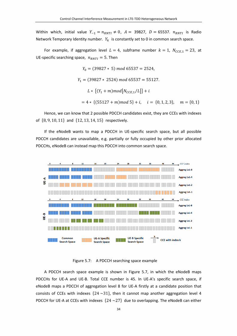
Figure 5.7: A PDCCH searching space example
A PDCCH search space example is shown in Figure 5.7, in which the eNodeB maps
PDCCHs for UE-A and UE-B. Total CCE number is 45. In UE-A’s specific search space, if
eNodeB maps a PDCCH of aggregation level 8 for UE-A firstly at a candidate position that
consists of CCEs with indexes {24 ~31}, then it cannot map another aggregation level 4
PDCCH for UE-A at CCEs with indexes {24 ~27} due to overlapping. The eNodeB can either

Control Channel Interference Measurement in LTE-TDD Heterogeneous Network
35
choose CCEs with indexes {20 ~23}, or in case overlapping still exist, choose CCEs of
indexes {0 ~3} , indexes {4 ~7} , indexes {8 ~11} or indexes {12 ~15} in common
searching space instead. Similarly if eNodeB maps an UE specific PDCCH of aggregation level
8 at CCEs with indexes {24 ~31} for UE-B firstly, then it cannot map a PDCCH for UE-A at
any candidates that contain a CCE with index of {24 ~31}. Thereby, it should choose an
un-overlapped candidate in UE specific searching space, or alternatively one in common
searching space.
5.4 PDSCH
Physical Downlink Shared Channel (PDSCH) is utilized for transmitting Downlink Share
Channel (DL-SCH) in transport layer that carries the Downlink data for UE. PDSCH region
starts from the OFDM symbol next to the last ODFM symbol of the control region. In
subframe 1 and subframe 6, due to the presence of Primary Synchronization Signal (PSS), the
OFDM symbol 2 cannot be used by PDSCH. Similarly, due to the presence of Secondary
Synchronization Signal (SSS) in the subframes 0 and subframe 5, PDSCH cannot use a part of
last symbol in these subframes.
The PDSCH payload, DL-SCH bits [𝑎0,𝑎1, … ,𝑎𝐴−1 ] will respectively undergo CRC
attachment, code block segmentation, code block CRC attachment, channel coding, rate
matching and block concatenation during physical layer processing. Unlike control channels,
PDSCH can choose QPSK, QAM16 or QAM64 as modulation scheme, for providing diverse
data rates selection.
The modulated complex-valued symbols will be mapped into data region of the DL
subframe.
Figure 5.8: PDSCH physical layer procedures

Control Channel Interference Measurement in LTE-TDD Heterogeneous Network
36
Chapter 6
UE Downlink Decoding Procedures For UE, the Downlink decoding is processed as an inverse procedure compared to
eNodeB encoding. The UE uses decoded PDCCH for getting instruction of decoding data in
PDSCH or for receiving scheduling grants of PUSCH.
The UE processing starts by decoding PCFICH. It is a reverse procedure of eNodeB
encoding it. After that UE will know how many OFDM symbols are configured for control
region. The PCFICH is always located in the first OFDM symbol. Its REG’s position depends on
the Cell Identity number. After decoding PCFICH, UE proceeds with checking PHICH and
identifying the ACK/NACK of Uplink data.
The most sophisticated process for control channels is the decoding of PDCCH. Since UE
does not know which message was sent, it uses blind decoding strategy. Considering
multiple PDCCH candidates exist, UE is unaware of PDCCH position, aggregation level and
DCI format. In addition, as analyzed in Chapter 5.3, more than one PDCCH for a single UE
may coexist within a subframe. Thereby, UE needs to search through all potential positions
with all possible sizes to ensure capturing all the transmitted PDCCH messages. The structure
of common search space and UE-specific search space helps to narrow down the blind
decoding trials.
Figure 6.1: UE Downlink physical layer decoding procedures

Control Channel Interference Measurement in LTE-TDD Heterogeneous Network
37
Figure 6.1 illustrates the DL physical layer decoding procedures. Below we introduce the
basic content of each step.
Step 1. Decode OFDM symbols in received subframe and recover complex-valued
symbols in them. In a DL subframe, the receiver removes the cyclic prefix and performs
N-Point FFT. If the delay of a multi-path component is within the size of cyclic prefix, it can
be successfully decoded.
Step 2. Decode the PCFICH and obtain the CFI value. This step is conducted using
correlation detection. The correlator checks for three different 32-bit codewords 𝐵𝑟 = <𝑏𝑟,0,𝑏𝑟,1, … , 𝑏𝑟,31 >, (𝑛 = 1, 2, 3), which introduced in Table 5.2. The positions of the
codeword’s REGs are computed using the same algorithm that eNodeB used for PCFICH
allocation. After QPSK demodulation and descrambling (Cell ID), estimate of the codeword
𝐵′ = < 𝑏0′ ,𝑏1′ , … , 𝑏31′ > is obtained. Respectively multiplying 𝐵′ by 𝐵𝑟, (𝑛 = 1, 2, 3) , UE
can determine the CFI value. The determined CFI value should ensure the maximum
correlation result.
𝑚𝑎𝑥(𝐵′ ∗ 𝐵𝑟) = 𝑚𝑎𝑥� �𝑏𝑘′ ∗ 𝑏𝑟,𝑘�31
𝑘=0
, 𝑛 = 1, 2, 3
Step 3. Decode the PHICH, obtain the ACK/NACK of physical layer H-ARQ. UE uses the
same algorithm as described in Chapter 5.2, finding PHICH group’s REGs position from
received subframe, based on its own 𝑛𝑃𝑃𝐼𝐶𝑃𝑔𝑔𝑔𝑔𝑔 value.
For a system with one PHICH group and normal cyclic prefix, if eNodeB send three
repeated modulated ACK/NACK symbols < 𝑎𝑠,𝑎𝑠,𝑎𝑠 > , 12 complex-valued PHICH
symbols (distributed in 3 REGs) will be retrieved by UE from first OFDM symbol in DL
subframe, marked as < 𝑎�1,𝑎�2, … ,𝑎�12 > . As shown in Table 5.4,
𝑆𝑘 = < 𝐸𝑘,1, 𝐸𝑘,2, 𝐸𝑘,3, 𝐸𝑘,4 >, (𝑘 = 0,1, … , 7) are orthogonal sequences used in one PHICH
group.
< 𝑎�1,𝑎�2, … ,𝑎�12 > = �(< 𝑎𝑘 ,𝑎𝑘 ,𝑎𝑘 > × 𝑆𝑘)7
𝑘=0
𝑆𝑠 = < 𝐸𝑠,1, 𝐸𝑠,2, 𝐸𝑠,3, 𝐸𝑠,4 > sequence corresponding to UE’s own 𝑛𝑃𝑃𝐼𝐶𝑃𝑠𝑐𝑠 will help
split 3-Symbol codeword from other multiplexed ones, due to sequence orthogonality.
< 𝑎�1,𝑎�2, … ,𝑎�12 > ∗ < 𝑆𝑠,𝑆𝑠,𝑆𝑠 >
= � �(< 𝑎𝑘 ,𝑎𝑘 ,𝑎𝑘 > × 𝑆𝑘)7
𝑘=0
� ∗ < 𝑆𝑠,𝑆𝑠,𝑆𝑠 >

Control Channel Interference Measurement in LTE-TDD Heterogeneous Network
38
= < 𝑎𝑠 𝑆𝑠 ∗ 𝑆𝑠, 𝑎𝑠 𝑆𝑠 ∗ 𝑆𝑠, 𝑎𝑠 𝑆𝑠 ∗ 𝑆𝑠 >
+ � < 𝑎𝑘 𝑆𝑘 ∗ 𝑆𝑠, 𝑎𝑘 𝑆𝑘 ∗ 𝑆𝑠, 𝑎𝑘 𝑆𝑘 ∗ 𝑆𝑠 > 𝑘≠𝑠
= δ < 𝑎𝑘 ,𝑎𝑘 ,𝑎𝑘 > + 0
δ = 𝑆𝑠 ∗ 𝑆𝑠 = ��𝐸𝑠,𝑖 ∗ 𝐸𝑠,𝑖�4
𝑖=1
Depends on the sequence used, δ can be ±4. Demodulate the codeword < 𝑎𝑘 ,𝑎𝑘 ,𝑎𝑘 >
with BPSK scheme, UE will get the three repeated ACK/NACK bits.
Step 4. Conduct CCE indexing. According to the CFI value obtained in Step 2, UE knows
the size of the control region. It will count all REs within it that have not been occupied by
reference symbols, PCFICH or PHICH, etc. Using the same algorithm that eNodeB used during
REG and CCE indexing, UE obtains the CCEs number and positions.
Step 5. Blind PDCCH decoding. As explained in Chapter 5.3.3, PDCCHs are mapped into
UE-specific space and common space. UE will try decoding in both spaces on all candidate
code positions, regarding all possible DCI formats and aggregation levels.
For the searching of format 𝑘 DCI, of which length is 𝑀𝐷𝐶𝐼(𝑘), UE will first check
through the common searching space, starts with candidates of aggregation level 8, then on
those of aggregation level 4. After that UE-Specific Searching Space will be checked, start
from candidates of aggregation level 8 to those of level 1. The 16-bit CRC attachment is used
for determining whether PDCCH exists on each candidate position.
At each blind attempt, complex-valued symbols set of candidate 𝑚 is:
< 𝑎�𝑖(0),𝑎�𝑖(1), … ,𝑎�𝑖(𝑁𝑔,𝑖 − 1) >
𝑁𝑔,𝑖 indicates the symbols number at aggregation level 𝑔. The corresponding bits set after
QPSK demodulation is expressed below, 2𝑁𝑔,𝑖 is the bits number.
< 𝑏𝑖(0), 𝑏𝑖(1), … , 𝑏𝑖(2𝑁𝑔,𝑖 − 1) >
Since bits length of DCI format 𝑘 is 𝑀𝐷𝐶𝐼(𝑘), after tail biting convolutional encoding, its
length is 𝑁𝑠 = 3(𝑀𝐷𝐶𝐼(𝑘) + 16), where we consider 16-bit CRC attachment. These bits will
be repeated several times for fulfilling current aggregation level required length. The repeat
time can be calculated by:
𝑇 = �2𝑁𝑔,𝑖 (3𝑀𝐷𝐶𝐼(𝑘) + 48)⁄ �

Control Channel Interference Measurement in LTE-TDD Heterogeneous Network
39
The higher aggregation level it is, the lager space can be provided for big size DCI format.
The more important, under the bad channel conditions, large redundancy of periodical
repetition in high aggregation level enhances PDCCH successful decoding rate. If 𝑇 is zero,
it means REs number of current aggregation level is insufficient for target DCI format. UE will
directly jump over this aggregation level. Otherwise, UE can find the potential DCI bits. The
DCI bits with CRC attached after channel coding is:
< 𝑐𝑖(0), 𝑐𝑖(1), … , 𝑐𝑖(𝑁𝑠 − 1) >
Taking advantage of the bits repetition,
�̂�𝑖(𝑛) =
⎩⎪⎨
⎪⎧�𝑏𝑖(𝑛 + 𝑙 ∗ 𝑁𝑠) 0 ≤ 𝑛 ≤ (2𝑁𝑔,𝑖 𝑚𝑁𝑑 𝑁𝑠) − 1
𝑇
𝑐=0
� 𝑏𝑖(𝑛 + 𝑙 ∗ 𝑁𝑠)𝑇−1
𝑐=0
(2𝑁𝑔,𝑖 𝑚𝑁𝑑 𝑁𝑠) ≤ 𝑛 ≤ 𝑁𝑠 − 1
After de-interleaving and tail biting convolutional decoding, UE will retrieve the DCI and CRC
bits:
< 𝑑𝑖(0),𝑑𝑖(1), … ,𝑑𝑖�𝑀𝐷𝐶𝐼(𝑘) − 1�,𝑑𝐶𝐶𝐶,0,𝑑𝐶𝐶𝐶,1, … ,𝑑𝐶𝐶𝐶,15 >
Descrambling the UE RNTI and removing antenna selection mask from last 16-bit CRC
codeword, the outgoing CRC bits < 𝑑𝐶𝐶𝐶,0′ , 𝑑𝐶𝐶𝐶,1
′ , … ,𝑑𝐶𝐶𝐶,15′ > will go through CRC check.
The CRC check uses the same generator polynomial 𝑔𝐶𝐶𝐶16(𝐷) introduced in Chapter 5.3.2.
A zero remainder after dividing < 𝑑𝐶𝐶𝐶,0′ , 𝑑𝐶𝐶𝐶,1
′ , … ,𝑑𝐶𝐶𝐶,15′ > with the polynomial
𝑔𝐶𝐶𝐶16(𝐷) indicates a correct received PDCCH for the UE and UE can proceed with decoding
the DCI bits. The data bits < 𝑑𝑖(0),𝑑𝑖(1), … ,𝑑𝑖�𝑀𝐷𝐶𝐼(𝑘) − 1� > in DCI format 𝑘
codeword will be passed to upper layer for further processing. The upper layer parses the
bits and extracts the information confined in the message. Otherwise, an un-zero remainder
reveals the absence of PDCCH on this candidate or an error reception happened.
After finishing one trial, UE will continue iterate to the next PDCCH candidate position
until all candidates have been checked through.
Step 6. Extract the embedded message from the successful fetched DCI bits.
Step 7. Decoded DCI message from step 6 carries either PDSCH data allocation and
modulation scheme or PUSCH resource grant. Based on the DCI information, UE will be
capable of extracting PDSCH data from DL subframe, as well as conducting PUSCH symbols
transmission in the authorized resource blocks in the UL subframes.
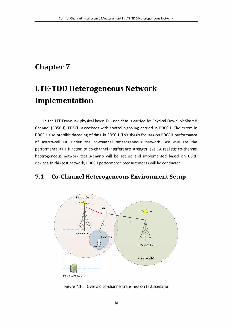
Control Channel Interference Measurement in LTE-TDD Heterogeneous Network
40
Chapter 7
LTE-TDD Heterogeneous Network Implementation
In the LTE Downlink physical layer, DL user data is carried by Physical Downlink Shared
Channel (PDSCH). PDSCH associates with control signaling carried in PDCCH. The errors in
PDCCH also prohibit decoding of data in PDSCH. This thesis focuses on PDCCH performance
of macro-cell UE under the co-channel heterogeneous network. We evaluate the
performance as a function of co-channel interference strength level. A realistic co-channel
heterogeneous network test scenario will be set up and implemented based on USRP
devices. In this test network, PDCCH performance measurements will be conducted.
7.1 Co-Channel Heterogeneous Environment Setup
Figure 7.1: Overlaid co-channel transmission test scenario

Control Channel Interference Measurement in LTE-TDD Heterogeneous Network
41
To simulate a simple co-channel heterogeneous network, we set up a test scenario as
displayed in Figure 7.1. The realistic test system contains four nodes. One macro-cell eNodeB
works as the primary BS to which the UE is attached. This eNodeB is called MeNodeB-1. The
other macrocell MeNodeB-2 works as an adjacent macro-cell. A third node is configured to
be a HeNodeB. It provides femto-cell coverage service inside the MeNodeB-1 coverage area.
The UE is communicating with MeNodeB-1. However, its position is close to HeNodeB,
of which the signal is received by UE as co-channel interference. The signal from MeNodeB-2
is also received by UE as interference.
Usually in an LTE-TDD heterogeneous network, femto-cell should coordinate the DL/UL
switching time and configuration type with macro-cell, in order to avoid the overlapping
between their DL subframes and UL subframes. In co-channel environment, the timing
mismatched transmission will cast severe interference on the opposite link direction [23].
For example, a macro-cell UE receiving DL data from a distant macro-cell eNodeB may suffer
connection blocking if a femto-cell UE nearby is transmitting its UL data with high power.
Research in [31] also indicates that if a macro-cell UE stays close to a femto HeNodeB
which has CSG strategy will the UE suffer cell outage problem. The macro-cell UE receives a
strong signal from HeNodeB but is refused to access. Meanwhile, it receives a relatively
weaker signal from a macro-cell eNodeB that actually serves it. Compared to femto-cell UEs,
macro-cell UEs are more vulnerable to the inter-cell interference brought by co-channel
heterogeneous deployment.
On the other hand, PDCCH plays an important role in communication. Since the
signaling and resource grant information that PDCCH carriers is the prerequisite for a UE to
access the data channel (PDSCH). Fail in decoding PDCCH will automatically lead the UE to
abandon the data channel content. Considering the PDCCH uses convolutional encoding
while the data channel has stronger turbo encoding, the PDCCH is less robust against
interference compared to the data channel.
Hence, it is very interesting and meaningful to evaluate the macro-cell PDCCH
performance under the co-channel deployed heterogeneous network. We will measure the
macro-cell PDCCH reception quality at the macro-cell UE according to the model shown in
Figure 7.1. We want to present how well the macro-cell PDCCH can tolerate the co-channel
interference and what extent of performance degradation will macro-cell PDCCH suffer.
Received PDCCH block error rate (BLER) and PDCCH payload (DCI bits) bit error rate (BER)
will be used as the criteria for PDCCH performance measurement.
In a heterogeneous network, providing precise synchronization of eNodeBs radio frame
and DL/UL switching moment is a significant challenge. HeNodeB can adopt different

Control Channel Interference Measurement in LTE-TDD Heterogeneous Network
42
methods to achieve time alignment or synchronization with MeNodeB, like using GPS,
adding signaling via core network or synchronize over the air. HeNodeB is usually installed
and connected to operator’s core network via subscriber’s own internet connection. As a
consequence, its backhaul signaling traffic quantity and quality cannot compete with the
dedicated connection that links macro-cell eNodeB to the core network. Capturing this
situation, we use over the air synchronization method in the thesis, since it does not need
the support of backhaul signaling and is relatively easy to implement. During DL subframes,
HeNodeB works similar to a UE. By tracking the synchronization reference signal (PSS) in
MeNodeB-1’s subframe, HeNodeB aligns its own radio frame to that of MeNodeB. The
drawback of over the air synchronization is that it will significantly increase the HeNodeB
system complexity.
In our test set up, Macro-Cell-1 and Macro-Cell-2 belong to the same operator, and they
are assigned with different Cell Identity Numbers (Cell-IDs), 0 and 1 respectively. Since
HeNodeB may be unaware of the detailed configuration of primary MeNodeB-1, their Cell
IDs may happen to be same. In order to test the extreme situation, the identity of femto-cell
is set to be same as that of Macro-Cell-1. The Cell-ID provides seeds for spreading codes, and
positions of reference signals, PHICH and PCFICH inside the subframe. The same Cell-ID
means that the cells have exactly overlapping channel allocations. The transmitters interfere
more severely compared to different Cell-ID case.
7.2 USRP Based Implementation
Figure 7.2: USRP based eNodeB and UE implementation
In the experiment, we use the Ettus Research USRP N200 device to work as radio front
end, transmitting and receiving RF signals. The ADC/DAC and Up Conversion/Down
Conversion of RF signal are also conducted inside USRP. The USRP is connected to a Linux PC
(with Ubuntu 12.04) via gigabit Ethernet cable with UDP connection. The digital baseband
signal is sent to/received from USRP device. The Linux PC is in charge of running baseband
processing code that is implemented by C++ program. The basic approach of using
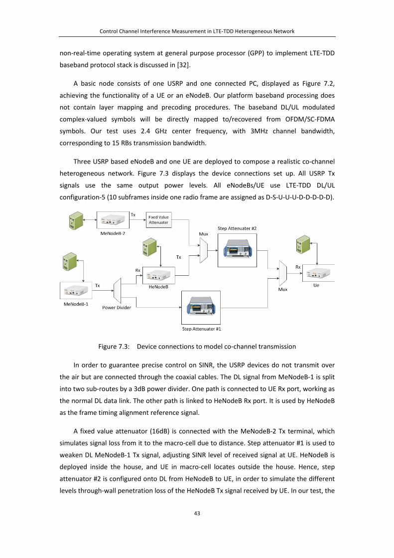
Control Channel Interference Measurement in LTE-TDD Heterogeneous Network
43
non-real-time operating system at general purpose processor (GPP) to implement LTE-TDD
baseband protocol stack is discussed in [32].
A basic node consists of one USRP and one connected PC, displayed as Figure 7.2,
achieving the functionality of a UE or an eNodeB. Our platform baseband processing does
not contain layer mapping and precoding procedures. The baseband DL/UL modulated
complex-valued symbols will be directly mapped to/recovered from OFDM/SC-FDMA
symbols. Our test uses 2.4 GHz center frequency, with 3MHz channel bandwidth,
corresponding to 15 RBs transmission bandwidth.
Three USRP based eNodeB and one UE are deployed to compose a realistic co-channel
heterogeneous network. Figure 7.3 displays the device connections set up. All USRP Tx
signals use the same output power levels. All eNodeBs/UE use LTE-TDD DL/UL
configuration-5 (10 subframes inside one radio frame are assigned as D-S-U-U-U-D-D-D-D-D).
Figure 7.3: Device connections to model co-channel transmission
In order to guarantee precise control on SINR, the USRP devices do not transmit over
the air but are connected through the coaxial cables. The DL signal from MeNodeB-1 is split
into two sub-routes by a 3dB power divider. One path is connected to UE Rx port, working as
the normal DL data link. The other path is linked to HeNodeB Rx port. It is used by HeNodeB
as the frame timing alignment reference signal.
A fixed value attenuator (16dB) is connected with the MeNodeB-2 Tx terminal, which
simulates signal loss from it to the macro-cell due to distance. Step attenuator #1 is used to
weaken DL MeNodeB-1 Tx signal, adjusting SINR level of received signal at UE. HeNodeB is
deployed inside the house, and UE in macro-cell locates outside the house. Hence, step
attenuator #2 is configured onto DL from HeNodeB to UE, in order to simulate the different
levels through-wall penetration loss of the HeNodeB Tx signal received by UE. In our test, the

Control Channel Interference Measurement in LTE-TDD Heterogeneous Network
44
attenuation is set to be 20dB and 40dB respectively, adjusting the influence brought by
femto-cell to macro-cell.
HeNodeB is designed to coordinate its transmission with overlaid MeNodeB-1. The idea
of this kind of time synchronization is to enforce HeNodeB keep tracking PSS signal in
MeNodeB-1’s DL subframe, conducting radio frame time alignment. This working mode
helps eliminate the UL/DL overlapping interference between femto-cell and macro-cell.
Under this mode, HeNodeB DL and MeNodeB-1 UL subframes will not overlap, neither will
HeNodeB UL and MeNodeB-1 DL subframes.
7.3 Control Group with Single eNodeB In the co-channel heterogeneous deployment of HeNodeB and MeNodeB, the
transmission of HeNodeB inside a building will always cause co-channel interference to the
macro-cell. In general, the penetration loss due to building walls can only alleviate the
interference level but will not totally remove it.
In order to compare the PDCCH performance degradation in heterogeneous co-channel
transmission versus ideal transmission, we set up a single eNodeB environment as the
control group, for simulating an ideal environment that contains no inter-cell interference. In
this case, HeNodeB and MeNodeB-2 are not present.
Figure 7.4: Single eNodeB transmission scenario
For simplicity, a system consists of one eNodeB and one UE is used, shown in Figure 7.4.
A macro-cell MeNodeB is directly connected to UE via coaxial cable. A step attenuator inside
the DL signal path is configured to control the UE received signal SINR level.
We will study the comparison between single eNodeB transmission and co-channel
heterogeneous transmission. The results are presented in the next chapter.
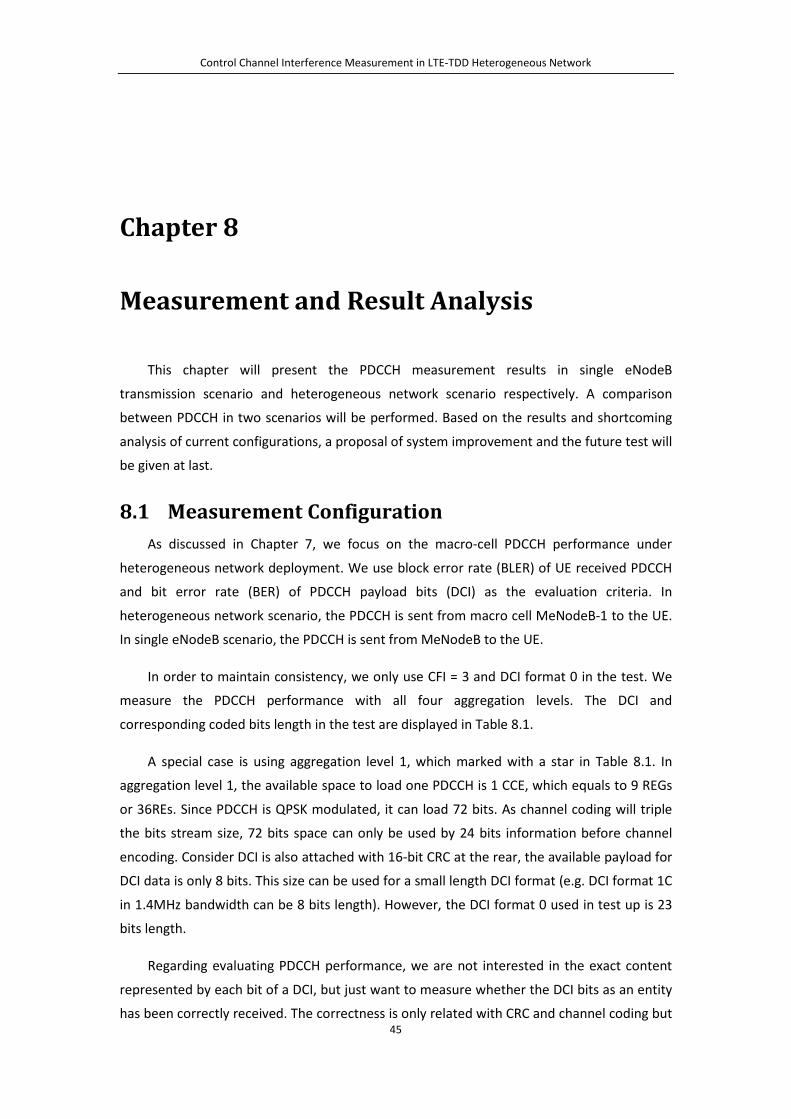
Control Channel Interference Measurement in LTE-TDD Heterogeneous Network
45
Chapter 8
Measurement and Result Analysis
This chapter will present the PDCCH measurement results in single eNodeB
transmission scenario and heterogeneous network scenario respectively. A comparison
between PDCCH in two scenarios will be performed. Based on the results and shortcoming
analysis of current configurations, a proposal of system improvement and the future test will
be given at last.
8.1 Measurement Configuration As discussed in Chapter 7, we focus on the macro-cell PDCCH performance under
heterogeneous network deployment. We use block error rate (BLER) of UE received PDCCH
and bit error rate (BER) of PDCCH payload bits (DCI) as the evaluation criteria. In
heterogeneous network scenario, the PDCCH is sent from macro cell MeNodeB-1 to the UE.
In single eNodeB scenario, the PDCCH is sent from MeNodeB to the UE.
In order to maintain consistency, we only use CFI = 3 and DCI format 0 in the test. We
measure the PDCCH performance with all four aggregation levels. The DCI and
corresponding coded bits length in the test are displayed in Table 8.1.
A special case is using aggregation level 1, which marked with a star in Table 8.1. In
aggregation level 1, the available space to load one PDCCH is 1 CCE, which equals to 9 REGs
or 36REs. Since PDCCH is QPSK modulated, it can load 72 bits. As channel coding will triple
the bits stream size, 72 bits space can only be used by 24 bits information before channel
encoding. Consider DCI is also attached with 16-bit CRC at the rear, the available payload for
DCI data is only 8 bits. This size can be used for a small length DCI format (e.g. DCI format 1C
in 1.4MHz bandwidth can be 8 bits length). However, the DCI format 0 used in test up is 23
bits length.
Regarding evaluating PDCCH performance, we are not interested in the exact content
represented by each bit of a DCI, but just want to measure whether the DCI bits as an entity
has been correctly received. The correctness is only related with CRC and channel coding but
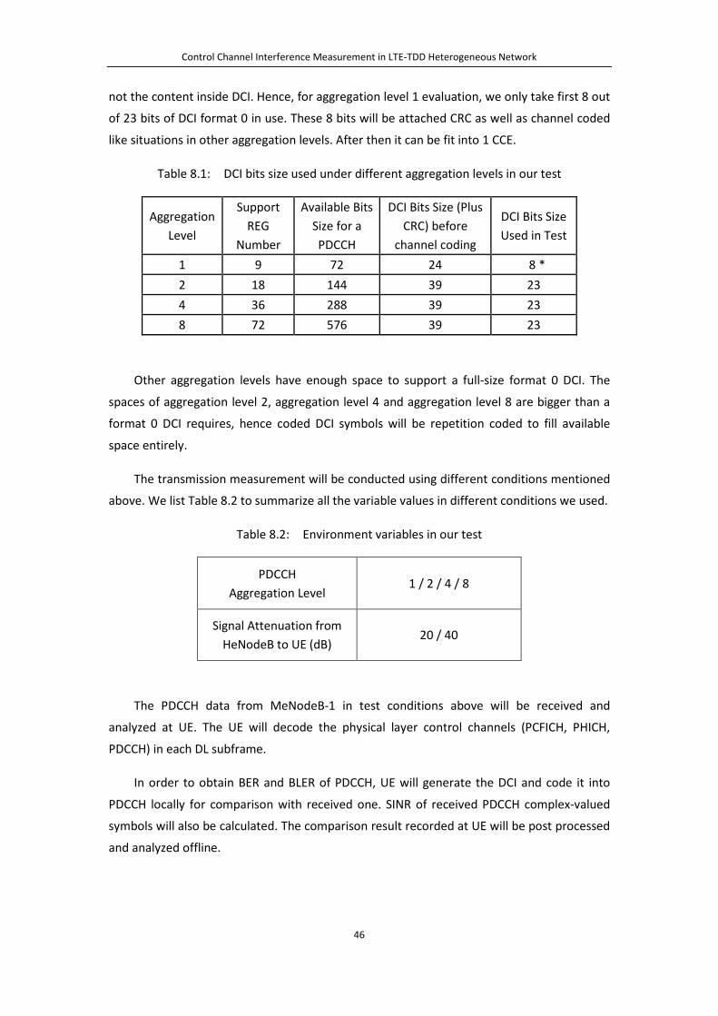
Control Channel Interference Measurement in LTE-TDD Heterogeneous Network
46
not the content inside DCI. Hence, for aggregation level 1 evaluation, we only take first 8 out
of 23 bits of DCI format 0 in use. These 8 bits will be attached CRC as well as channel coded
like situations in other aggregation levels. After then it can be fit into 1 CCE.
Table 8.1: DCI bits size used under different aggregation levels in our test
Aggregation Level
Support REG
Number
Available Bits Size for a PDCCH
DCI Bits Size (Plus CRC) before
channel coding
DCI Bits Size Used in Test
1 9 72 24 8 * 2 18 144 39 23 4 36 288 39 23 8 72 576 39 23
Other aggregation levels have enough space to support a full-size format 0 DCI. The
spaces of aggregation level 2, aggregation level 4 and aggregation level 8 are bigger than a
format 0 DCI requires, hence coded DCI symbols will be repetition coded to fill available
space entirely.
The transmission measurement will be conducted using different conditions mentioned
above. We list Table 8.2 to summarize all the variable values in different conditions we used.
Table 8.2: Environment variables in our test
PDCCH Aggregation Level
1 / 2 / 4 / 8
Signal Attenuation from HeNodeB to UE (dB)
20 / 40
The PDCCH data from MeNodeB-1 in test conditions above will be received and
analyzed at UE. The UE will decode the physical layer control channels (PCFICH, PHICH,
PDCCH) in each DL subframe.
In order to obtain BER and BLER of PDCCH, UE will generate the DCI and code it into
PDCCH locally for comparison with received one. SINR of received PDCCH complex-valued
symbols will also be calculated. The comparison result recorded at UE will be post processed
and analyzed offline.
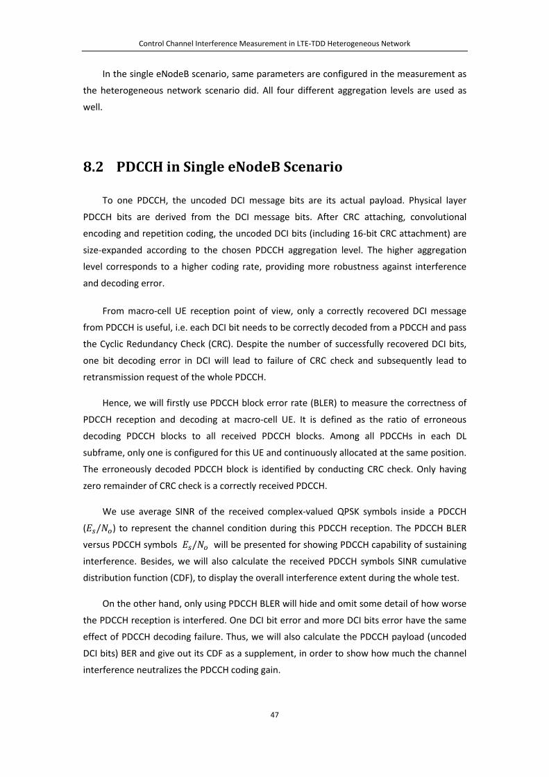
Control Channel Interference Measurement in LTE-TDD Heterogeneous Network
47
In the single eNodeB scenario, same parameters are configured in the measurement as
the heterogeneous network scenario did. All four different aggregation levels are used as
well.
8.2 PDCCH in Single eNodeB Scenario
To one PDCCH, the uncoded DCI message bits are its actual payload. Physical layer
PDCCH bits are derived from the DCI message bits. After CRC attaching, convolutional
encoding and repetition coding, the uncoded DCI bits (including 16-bit CRC attachment) are
size-expanded according to the chosen PDCCH aggregation level. The higher aggregation
level corresponds to a higher coding rate, providing more robustness against interference
and decoding error.
From macro-cell UE reception point of view, only a correctly recovered DCI message
from PDCCH is useful, i.e. each DCI bit needs to be correctly decoded from a PDCCH and pass
the Cyclic Redundancy Check (CRC). Despite the number of successfully recovered DCI bits,
one bit decoding error in DCI will lead to failure of CRC check and subsequently lead to
retransmission request of the whole PDCCH.
Hence, we will firstly use PDCCH block error rate (BLER) to measure the correctness of
PDCCH reception and decoding at macro-cell UE. It is defined as the ratio of erroneous
decoding PDCCH blocks to all received PDCCH blocks. Among all PDCCHs in each DL
subframe, only one is configured for this UE and continuously allocated at the same position.
The erroneously decoded PDCCH block is identified by conducting CRC check. Only having
zero remainder of CRC check is a correctly received PDCCH.
We use average SINR of the received complex-valued QPSK symbols inside a PDCCH
(𝐸𝑠/𝑁𝑔) to represent the channel condition during this PDCCH reception. The PDCCH BLER
versus PDCCH symbols 𝐸𝑠/𝑁𝑔 will be presented for showing PDCCH capability of sustaining
interference. Besides, we will also calculate the received PDCCH symbols SINR cumulative
distribution function (CDF), to display the overall interference extent during the whole test.
On the other hand, only using PDCCH BLER will hide and omit some detail of how worse
the PDCCH reception is interfered. One DCI bit error and more DCI bits error have the same
effect of PDCCH decoding failure. Thus, we will also calculate the PDCCH payload (uncoded
DCI bits) BER and give out its CDF as a supplement, in order to show how much the channel
interference neutralizes the PDCCH coding gain.
Control Channel Interference Measurement in LTE-TDD Heterogeneous Network
48
Figure 8.1: PDCCH symbol SINR (𝐸𝑠/𝑁𝑔) CDF (single eNodeB)
Figure 8.2: PDCCH payload (DCI bits) BER CDF (single eNodeB)
Figure 8.3: PDCCH BLER (single eNodeB)
In the single eNodeB transmission scenario, without external interference, four
different aggregation levels have close PDCCH symbols SINR CDF curves, displayed in Figure
8.1. The different coding rates on these aggregation levels, however, provide different
performance on PDCCH BLER, which is shown in Figure 8.3. Usually, no more than 1% BLER is
required for PDCCH reception at UE. Apparently, the bigger aggregation level is used, the
lower SINR is needed to fulfill such requirement. In our test set up, using aggregation 8 gives
PDCCH close to a 4 dB advance than aggregation 1 to reach this goal.
When comes to PDCCH payload bits (uncoded DCI message bits) BER CDF result, which
displayed in Figure 8.2, a strange situation can be witnessed. Among aggregation level 1, 2
and 4, the higher aggregation level has better BER CDF performance, which fits the

Control Channel Interference Measurement in LTE-TDD Heterogeneous Network
49
expectation since higher coding rate should have more robustness. However, DCI bits BER
CDF of aggregation level 8 is worse than that of aggregation level 4 and stays close to those
of aggregation level 1 and 2.
This phenomenon indicates some implementation loss may exist in our system, which
makes the PDCCH loss some coding gain in some circumstances, especially when aggregation
level 8 is used. It may impact the PDCCH BLER and BER measurement accuracy. For example,
PDCCH BLER versus SINR curve of aggregation level 8 in Figure 8.3 could be even better
(although it is already better than other aggregation levels).
8.3 Macro-cell PDCCH in Heterogeneous Network
Under co-channel deployment, the HeNodeB and the MeNodeB use same frequency
band and run simultaneously in a heterogeneous network. As discussed in model
implementation in Chapter 7.1, HeNodeB will actively coordinate its radio frame with
MeNodeB-1. As a consequence, PDCCHs from two eNodeBs will overlap in the control
region.
Figure 8.4: Spectrogram of overlapped DL subframe of HeNodeB and MeNodeB-1
The control region on DL subframe of MeNodeB-1 is configured to be fully loaded with
the maximum possible number of PDCCHs while the HeNodeB’s PDCCHs only use one third
of the control region. The Figure 8.4 displayed the spectrogram of a DL radio subframe
measured at UE, which is 14 symbols × 18 subcarriers in size. The color difference between
regions presents the received symbols relative energy level. Areas with highest energy level

Control Channel Interference Measurement in LTE-TDD Heterogeneous Network
50
are synchronization symbols and cell specific reference symbols, which appear as dark red.
We can spot that color in first several symbols of the subframe is relatively brighter than the
rest of control region. It indicates PDCCHs of MeNodeB-1 and HeNodeB are overlapped
there, leading to higher received symbol energy. Our target PDCCH (from macro-cell
MeNodeB-1 to UE) is located inside the overlapping area.
The result of the heterogeneous network scenario will be compared with the single
eNodeB transmission situation (the control group), for displaying the potential PDCCH
performance degradation (on BLER, payload BER CDF and SINR CDF) brought by co-channel
heterogeneous deployment.
As introduced in Chapter 7.2, at the heterogeneous scenario, the co-channel
interference from HeNodeB to macro-cell UE will be attenuated by 20 dB and 40 dB
respectively. The less attenuation, the more co-channel interference macro-cell UE will
receive. The PDCCH BLER, PDCCH symbols SINR (𝐸𝑠/𝑁𝑔) CDF and DCI bits BER CDF under
such two situations will be measured and compared to the single eNodeB scenario. This kind
of comparison will be performed at each PDCCH aggregation level.
When using aggregation level 1, the results are displayed in Figure 8.5, Figure 8.6 and
Figure 8.7.
Figure 8.5: PDCCH symbol SINR (𝐸𝑠/𝑁𝑔) CDF (use PDCCH aggregation level 1)
Figure 8.6: PDCCH payload (DCI bits) BER CDF (use PDCCH aggregation level 1)

Control Channel Interference Measurement in LTE-TDD Heterogeneous Network
51
Figure 8.7: PDCCH BLER (use PDCCH aggregation level 1)
In the co-channel heterogeneous network, the macro-cell UE received PDCCH 𝐸𝑠/𝑁𝑔
CDF curves (in Figure 8.5) and PDCCH payload DCI message bits BER CDF curves (in Figure 8.6)
are both deteriorated compared to single eNodeB scenario. The deterioration extent
corresponds to co-channel interference strength.
On the other hand, the PDCCH BLER v.s. PDCCH 𝐸𝑠/𝑁𝑔 only shows a small difference
between co-channel heterogeneous network and single eNodeB scenario (in Figure 8.7).
Next we test PDCCH aggregation level 2. The received PDCCH 𝐸𝑠/𝑁𝑔 CDF curves (in
Figure 8.8) and the PDCCH payload DCI message bits BER CDF curves (in Figure 8.9) are still
deteriorated compared to single eNodeB scenario. In addition, PDCCH payload BER CDF
deterioration is corresponding to the co-channel intereference level from HeNodeB as well.
Figure 8.8: PDCCH symbol SINR (𝐸𝑠/𝑁𝑔) CDF (use PDCCH aggregation level 2)
Figure 8.9: PDCCH payload (DCI bits) BER CDF (use PDCCH aggregation level 2)
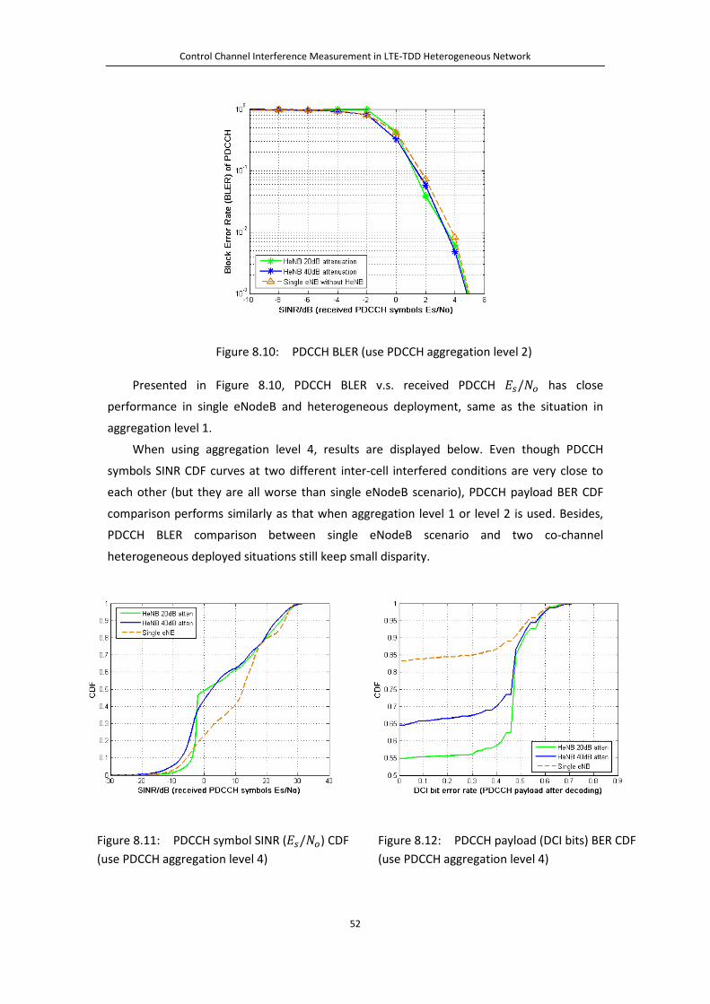
Control Channel Interference Measurement in LTE-TDD Heterogeneous Network
52
Figure 8.10: PDCCH BLER (use PDCCH aggregation level 2)
Presented in Figure 8.10, PDCCH BLER v.s. received PDCCH 𝐸𝑠/𝑁𝑔 has close
performance in single eNodeB and heterogeneous deployment, same as the situation in
aggregation level 1.
When using aggregation level 4, results are displayed below. Even though PDCCH
symbols SINR CDF curves at two different inter-cell interfered conditions are very close to
each other (but they are all worse than single eNodeB scenario), PDCCH payload BER CDF
comparison performs similarly as that when aggregation level 1 or level 2 is used. Besides,
PDCCH BLER comparison between single eNodeB scenario and two co-channel
heterogeneous deployed situations still keep small disparity.
Figure 8.11: PDCCH symbol SINR (𝐸𝑠/𝑁𝑔) CDF (use PDCCH aggregation level 4)
Figure 8.12: PDCCH payload (DCI bits) BER CDF (use PDCCH aggregation level 4)

Control Channel Interference Measurement in LTE-TDD Heterogeneous Network
53
Figure 8.13: PDCCH BLER (use PDCCH aggregation level 4)
At last, we test with aggregation level 8. PDCCH symbols SINR CDF and PDCCH payload
(DCI bits) BER CDF both reveal that co-channel heterogeneous deployment will deteriorate
their performance compared to single eNodeB deployment, similar as those happen in other
aggregation levels. However, unlike shown in other aggregation levels, PDCCH BLER v.s. SINR
curves comparison at aggregation level 8 performs differently (in Figure 8.16). When
HeNodeB to UE interference is attenuated by 20dB, macro-cell PDCCH BLER is degraded a lot
(approximately 5 dB) in co-channel heterogeneous scenarios compared to the single eNodeB
scenario. Such big degradation disappears when attenuation decreases to 40 dB where its
PDCCH BLER is very close to the single eNodeB scenario.
Figure 8.14: PDCCH symbol SINR (𝐸𝑠/𝑁𝑔) CDF (use PDCCH aggregation level 8)
Figure 8.15: PDCCH payload (DCI bits) BER CDF (use PDCCH aggregation level 8)
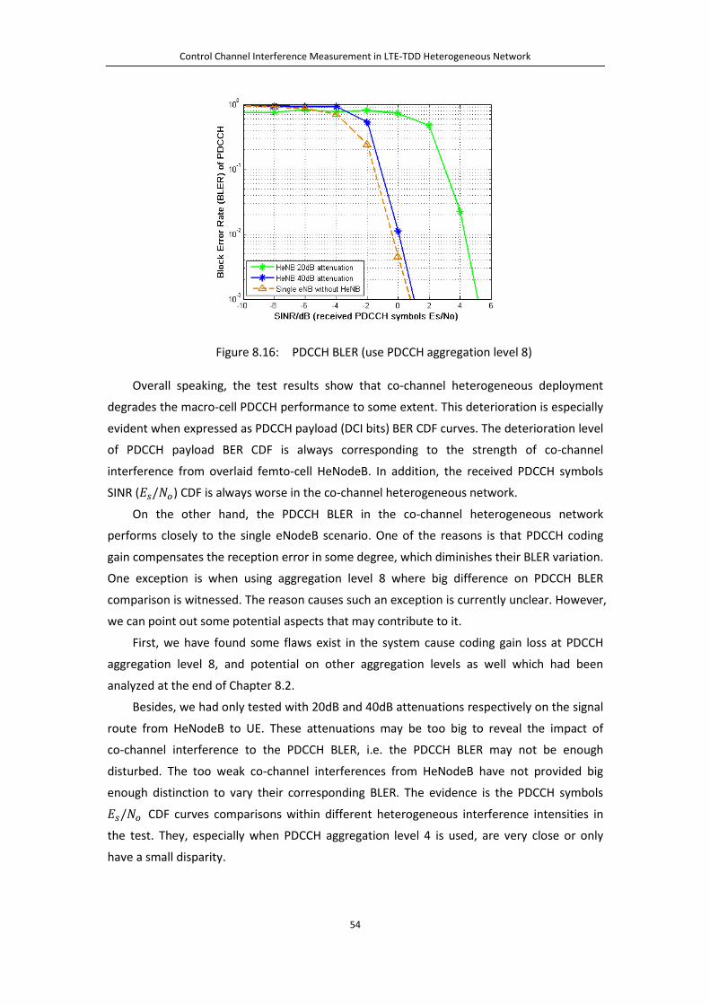
Control Channel Interference Measurement in LTE-TDD Heterogeneous Network
54
Figure 8.16: PDCCH BLER (use PDCCH aggregation level 8)
Overall speaking, the test results show that co-channel heterogeneous deployment
degrades the macro-cell PDCCH performance to some extent. This deterioration is especially
evident when expressed as PDCCH payload (DCI bits) BER CDF curves. The deterioration level
of PDCCH payload BER CDF is always corresponding to the strength of co-channel
interference from overlaid femto-cell HeNodeB. In addition, the received PDCCH symbols
SINR (𝐸𝑠/𝑁𝑔) CDF is always worse in the co-channel heterogeneous network.
On the other hand, the PDCCH BLER in the co-channel heterogeneous network
performs closely to the single eNodeB scenario. One of the reasons is that PDCCH coding
gain compensates the reception error in some degree, which diminishes their BLER variation.
One exception is when using aggregation level 8 where big difference on PDCCH BLER
comparison is witnessed. The reason causes such an exception is currently unclear. However,
we can point out some potential aspects that may contribute to it.
First, we have found some flaws exist in the system cause coding gain loss at PDCCH
aggregation level 8, and potential on other aggregation levels as well which had been
analyzed at the end of Chapter 8.2.
Besides, we had only tested with 20dB and 40dB attenuations respectively on the signal
route from HeNodeB to UE. These attenuations may be too big to reveal the impact of
co-channel interference to the PDCCH BLER, i.e. the PDCCH BLER may not be enough
disturbed. The too weak co-channel interferences from HeNodeB have not provided big
enough distinction to vary their corresponding BLER. The evidence is the PDCCH symbols
𝐸𝑠/𝑁𝑔 CDF curves comparisons within different heterogeneous interference intensities in
the test. They, especially when PDCCH aggregation level 4 is used, are very close or only
have a small disparity.

Control Channel Interference Measurement in LTE-TDD Heterogeneous Network
55
It will be interesting to check if configuring less attenuation, i.e. 10dB or 0dB, will the
much stronger inter-cell interference deteriorate PDCCH BLER performance more and lead
to evident difference compared to the single eNodeB situation.
At last, due to the software efficiency and limitation in the current system, the accuracy
of the result may be disturbed. The Linux workstation that controlled the HeNodeB had a
heavy calculation burden. Its functionality combines both eNodeB and UE. In each DL, it
needs to work parallel on synchronizing received subframe from MeNodeB-1 like an
ordinary UE, as well as preparing its own DL data like an ordinary eNodeB. The time
alignment algorithm must be done fast enough to ensure transmitting DL at correct time slot.
In our test, the software can only run less than one minute before crashing. Hence, the
samples number we received was not very big. We also found that HeNodeB sometimes
dropped several consecutive received subframes that would lead to the abandon of DL
transmission in those subframes.
Research in [32] also reveals the shortcomings in such an SDR platform that runs on the
general purpose processor with un-real-time operating system. They include packets loss in
UDP communication between USRP and PC, frequency offset due to the USRP local oscillator
inaccuracy, etc.
These problems will interfere the correctness of the test result.
8.4 Improvement on Test and Further Measurement In this thesis, we built an SDR based test environment of heterogeneous LTE-TDD
networks. We measured the macro-cell PDCCH performance when an overlapped femto-cell
HeNodeB casted co-channel interference on it. In our test, we added 20dB and 40dB
attenuations on HeNodeB output signal respectively. It revealed that PDCCH performance in
the heterogeneous network would be deteriorated to some extent compared to the single
eNodeB transmission scenario. When expressed as PDCCH payload BER CDF curves
comparison, such deterioration is evident. When expressed as PDCCH BLER v.s. received
PDCCH symbols SINR, the difference becomes very slight.
Based on shortage and problems analysis at the end of Chapter 8.3, in the future
measurement we could test the configurations with 10dB and even 0dB attenuation levels
on HeNodeB output. Check the macro-cell PDCCH performance under much stronger
interference.
Besides, in the current test we enforce HeNodeB to coordinate radio frame timing with
MeNodeB-1, or work in a “synchronous mode”. Even though it avoids the interference from
femto and macro cells’ DL/UL subframes overlapping, it significantly increases HeNodeB
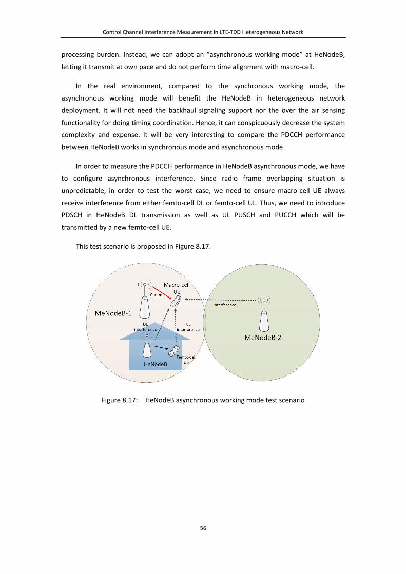
Control Channel Interference Measurement in LTE-TDD Heterogeneous Network
56
processing burden. Instead, we can adopt an “asynchronous working mode” at HeNodeB,
letting it transmit at own pace and do not perform time alignment with macro-cell.
In the real environment, compared to the synchronous working mode, the
asynchronous working mode will benefit the HeNodeB in heterogeneous network
deployment. It will not need the backhaul signaling support nor the over the air sensing
functionality for doing timing coordination. Hence, it can conspicuously decrease the system
complexity and expense. It will be very interesting to compare the PDCCH performance
between HeNodeB works in synchronous mode and asynchronous mode.
In order to measure the PDCCH performance in HeNodeB asynchronous mode, we have
to configure asynchronous interference. Since radio frame overlapping situation is
unpredictable, in order to test the worst case, we need to ensure macro-cell UE always
receive interference from either femto-cell DL or femto-cell UL. Thus, we need to introduce
PDSCH in HeNodeB DL transmission as well as UL PUSCH and PUCCH which will be
transmitted by a new femto-cell UE.
This test scenario is proposed in Figure 8.17.
Figure 8.17: HeNodeB asynchronous working mode test scenario

Control Channel Interference Measurement in LTE-TDD Heterogeneous Network
57
Chapter 9
Conclusion
Femto-cell provides short-range cellular accessing service inside a building. It is easy to
deploy, as it can be connected into an operator’s core network via broadband cable in the
building, without requiring sophisticated control signaling. It is an efficient supplement in
indoor environments for providing coverage enhancement that conventional outdoor
macro-cell networks cannot achieve, due to the penetration loss of building walls. In an LTE
co-channel heterogeneous network, femto-cells that geographically locate inside a
macro-cell, reuse the same frequency band as the macro-cell. The building penetration loss
helps to alleviate the inter-cell interference. The spatial reuse of frequency provides
enhanced capacity, compared to conventional way of spectrum partitioning between macro
and femto cells. However, we still need to pay attention to inter-cell interference in
co-channel transmission circumstance, in order to protect both macro-cell and femto-cell.
Some special procedures like transmission power control [33] or cell identity number
manipulation [19] can be adopted to mitigate the interference from femto-cell to macro-cell.
In this thesis, analysis of LTE-TDD heterogeneous network is focused on the
interference on Physical Downlink Control Channel (PDCCH) brought by co-channel
deployment. The ability of macro-cell PDCCH to sustain interference is evaluated by
measurements on the test platform implemented during the thesis. PDCCH received Block
Error Rate (BLER), PDCCH payload (DCI bits) BER and received PDCCH symbols SINR (𝐸𝑠/𝑁𝑔)
are measured at macro-cell UE. We deploy software define radio devices (Ettus Research
USRP 200 terminals) to work as eNodeB or UE, for simulating a co-channel heterogeneous
environment. Linux workstations are connected to each USRP, running the baseband
algorithms and processing software compiled from C++ code. Two macro-cell eNodeBs
(MeNodeB), one femto-cell eNodeB (HeNodeB) as well as a macro-cell UE are set up. In the
test, femto-cell HeNodeB is deployed to align its radio frame to macro-cell MeNodeB, i.e.
synchronous mode.

Control Channel Interference Measurement in LTE-TDD Heterogeneous Network
58
Our test indicates that macro-cell PDCCH performance in a co-channel heterogeneous
network will degrade to some extent compared to single eNodeB transmission scenario. The
degradation mainly expresses in BER CDF of PDCCH payload (DCI message bits) and macro
UE received PDCCH symbols 𝐸𝑠/𝑁𝑔 CDF. The PDCCH BLER, however, maintains similar
performance compared to the single eNodeB scenario.
Based on the shortcoming of the current test set up, we also propose the improvement
on the test. Furthermore, we introduce another femto-cell working mode under
heterogeneous network for releasing HeNodeB calculation complexity, i.e. asynchronous
mode. The PDCCH performance comparison between the synchronous and the
asynchronous modes is also worth further investigation.

59
Reference
[1]. H. Shajaiah, A. Abdel-Hadi and C. Clancy, "Utility Proportional Fairness Resource
Allocation with Carrier Aggregation in 4G-LTE," IEEE Military Communications
Conference (MILCOM), pp.412-417, Nov 2013.
[2]. J. Wannstrom, “Carrier Aggregation explained,” Jun 2013. [Online]:
http://www.3gpp.org/technologies/keywords-acronyms/101-carrier-aggregation-expl
ained.
[3]. A. Khandekar, N. Bhushan, T. Ji, and V. Vanghi, “LTE-Advanced: Heterogeneous
networks,” European Wireless Conference (EW), pp. 978-982, Apr 2010.
[4]. V. Chandrasekhar, J.G. Andrews and A. Gatherer, "Femtocell networks: a survey," IEEE
Communications Magazine, vol.46, no.9, pp.59-67, Sep 2008.
[5]. D. Tsolkas, N. Passas and L. Merakos, "Alleviating control channel interference in
femto-overlaid LTE-advanced networks," IEEE Communications Magazine, vol.51,
no.10, pp.192-200, Oct 2013.
[6]. Y. Wang, Y. Chang and D. Yang, "An Efficient Inter-Cell Interference Coordination
Scheme in Heterogeneous Cellular Networks," IEEE Vehicular Technology Conference
(VTC Fall), pp.1-5, Sep 2012.
[7]. S. Rangan, “Femto-Macro Cellular Interference Control with Subband Scheduling and
Interference Cancelation,” IEEE GLOBECOM Workshops (GC Wkshps), pp.695-700, Dec
2010.
[8]. CISCO, “Cisco Universal Small Cell Solution: A Platform for Service Innovation,”
C22-733906-00, Feb 2015. [Online]: http://www.cisco.com/c/dam/en/us/solutions/
collateral/service-provider/small-cell-solutions/platform-for-service-innovation.pdf.
[9]. Small Cell Forum, “HeNB (LTE Femto) Network Architecture (Release 5),”
SCF025.05.01, Dec 2013. [Online]: http://scf.io/en/documents/025_HeNB_LTE_Femto
_network_architecture.php.

60
[10]. B. Li, "An Effective Inter-Cell Interference Coordination Scheme for Heterogeneous
Network," IEEE Vehicular Technology Conference (VTC Spring), pp.1-5, May 2011.
[11]. T. Yucek and H. Arslan, "A survey of spectrum sensing algorithms for cognitive radio
applications," IEEE Communications Surveys & Tutorials, vol.11, no.1, pp.116-130,
2009.
[12]. G. Li, J. Fang, H. Tan and J. Li, "The impact of time-bandwidth product on the energy
detection in the cognitive radio," IEEE Broadband Network and Multimedia
Technology Conference (IC-BNMT), pp.634-638, Oct 2010.
[13]. H. Tang, "Some physical layer issues of wide-band cognitive radio systems," IEEE New
Frontiers in Dynamic Spectrum Access Networks Symposium (DySPAN), pp.151-159,
Nov 2005.
[14]. T. Yucek and H. Arslan, "Spectrum Characterization for Opportunistic Cognitive Radio
Systems," IEEE Military Communications Conference (MILCOM), pp.1-6, Oct 2006.
[15]. Z. Bharucha, G. Auer and T. Abe, "Downlink femto-to-macro control channel
interference for LTE," IEEE Wireless Communications and Networking Conference
(WCNC), pp.1259-1264, Mar 2011.
[16]. CATT, “Analysis of Time-Partitioning Solution for Control Channel,” 3GPP TSG RAN
WG1 Meeting R1-103494, Jun–Jul 2010.
[17]. Y. Wang and K.I. Pedersen, "Performance Analysis of Enhanced Inter-Cell Interference
Coordination in LTE-Advanced Heterogeneous Networks," IEEE Vehicular Technology
Conference (VTC Spring), pp.1-5, May 2012.
[18]. 3GPP, “Evolved Universal Terrestrial Radio Access (E-UTRA); FDD Home eNodeB (HeNB)
Radio Frequency (RF) Requirements Analysis (Release 9),” TS 36.921 v9.0.0, Mar 2010.
[19]. Z. Bharucha, G. Auer, T. Abe and N. Miki, "Femto-to-Macro Control Channel
Interference Mitigation via Cell ID Manipulation in LTE," IEEE Vehicular Technology
Conference (VTC Fall), pp.1-6, Sep 2011.
[20]. S. Sesia, I. Toufik and M. Baker, “LTE - The UMTS Long Term Evolution: From Theory to
Practice,” 2nd ed, John Wiley & Sons, 2011.
[21]. 3GPP, “3rd generation partnership project; Technical specification group radio access
network; Physical Channels and Modulation (Release 8),” TS 36.211 v8.9.0, Dec 2009.

61
[22]. R. Ratasuk, A. Ghosh, W. Xiao, R. Love, R. Nory and B. Classon, "TDD design for UMTS
Long-Term Evolution," IEEE Personal, Indoor and Mobile Radio Communications
Symposium (PIMRC), pp.1-5, Sep 2008.
[23]. M. Rinne and O. Tirkkonen, “LTE, the radio technology path towards 4G,” Computer
Communications, vol.33, no.16, pp.1894-1906, Oct 2010.
[24]. J. Brown and J.Y. Khan, "Performance comparison of LTE FDD and TDD based Smart
Grid communications networks for uplink biased traffic," IEEE Smart Grid
Communications Conference (SmartGridComm), pp.276-281, Nov 2012.
[25]. E. Lähetkangas, K. Pajukoski, J. Vihriälä, G. Berardinelli, M. Lauridsen, E. Tiirola and P.
Mogensen, "Achieving low latency and energy consumption by 5G TDD mode
optimization," IEEE Communications Workshops (ICC), pp.1-6, Jun 2014.
[26]. D. Poulin, “FDD vs TDD Comparison,” Oct 2013. [Online]: http://www.slideshare.
net/darcypoulin/tdd-versus-fdd.
[27]. H. Holma and A. Toskala, “LTE for UMTS: OFDMA and SCFDMA Based Radio Access,”
1st ed, John Wiley & Sons, 2009.
[28]. 3GPP, “3rd generation partnership project; Technical specification. LTE; Evolved
Universal Terrestrial Radio Access (E-UTRA); User Equipment (UE) radio transmission
and reception (Release 8),” TS 36.101 v8.25.0, Sep 2014.
[29]. 3GPP, “3rd generation partnership project; Technical specification group radio access
network; Multiplexing and Channel Coding (Release 8),” TS 36.212 v8.8.0, Dec 2009.
[30]. 3GPP, “3rd generation partnership project; Technical specification group radio access
network; Physical Layer Procedures (Release 8),” TS 36.213 v8.8.0, Sep 2009.
[31]. P. Amin, O. Tirkkonen, T. Henttonen and E. Pernila, "Primary component carrier
selection for a heterogeneous network: A comparison of Selfish, Altruistic and
Symmetric Strategies," IEEE Wireless Communications and Networking Conference
Workshops (WCNCW), pp.115-119, Apr 2012.
[32]. J. Kerttula , N. Malm , K. Ruttik , R. Jäntti and O. Tirkkonen, “Implementing TD-LTE as
software defined radio in general purpose processor,” ACM Workshop on Software
Radio Implementation Forum, pp.61-68, Aug 2014.
[33]. X. Li, L. Qian and D. Kataria, "Downlink power control in co-channel macrocell
femtocell overlay," Information Sciences and Systems Conference (CISS), pp.383-388,
Mar 2009.