a-07 acl en aca drw180231ab 20181107
TRANSCRIPT
ACL Series
A-18
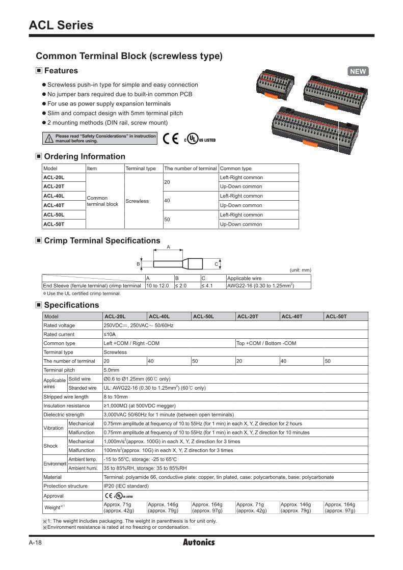
Common Terminal Block (screwless type)
Screwless push-in type for simple and easy connection No jumper bars required due to built-in common PCB For use as power supply expansion terminals Slim and compact design with 5mm terminal pitch 2 mounting methods (DIN rail, screw mount)
Features
Model ACL-20L ACL-40L ACL-50L ACL-20T ACL-40T ACL-50T
Rated voltage 250VDCᜡ, 250VACᜠ 50/60Hz
Rated current ≤10A
Common type Left +COM / Right -COM Top +COM / Bottom -COM
Terminal type Screwless
The number of terminal 20 40 50 20 40 50
Terminal pitch 5.0mm
Applicable wires
Solid wire Ø0.6 to Ø1.25mm (60 only)
Stranded wire UL: AWG22-16 (0.30 to 1.25mm2) (60 only)
Stripped wire length 8 to 10mm
Insulation resistance ≥1,000MΩ (at 500VDC megger)
Dielectric strength 3,000VAC 50/60Hz for 1 minute (between open terminals)
Vibration Mechanical 0.75mm amplitude at frequency of 10 to 55Hz (for 1 min) in each X, Y, Z direction for 2 hours
Malfunction 0.75mm amplitude at frequency of 10 to 55Hz (for 1 min) in each X, Y, Z direction for 10 minutes
ShockMechanical 1,000m/s2(approx. 100G) in each X, Y, Z direction for 3 times
Malfunction 100m/s2(approx. 10G) in each X, Y, Z direction for 3 times
EnvironmentAmbient temp. -15 to 55, storage: -25 to 65Ambient humi. 35 to 85%RH, storage: 35 to 85%RH
Material Terminal: polyamide 66, conductive plate: copper, tin plated, case: polycarbonate, base: polycarbonate
Protection structure IP20 (IEC standard)
Approval ᜢ
Weight※1 Approx. 71g(approx. 42g)
Approx. 146g(approx. 79g)
Approx. 164g(approx. 97g)
Approx. 71g(approx. 42g)
Approx. 146g(approx. 79g)
Approx. 164g(approx. 97g)
※1: The weight includes packaging. The weight in parenthesis is for unit only.※Environment resistance is rated at no freezing or condensation.
Please read “Safety Considerations” in instruction manual before using.
Ordering InformationModel Item Terminal type The number of terminal Common type
ACL-20L
Common terminal block Screwless
20Left-Right common
ACL-20T Up-Down common
ACL-40L40
Left-Right common
ACL-40T Up-Down common
ACL-50L50
Left-Right common
ACL-50T Up-Down common
Crimp Terminal Specifi cations
(unit: mm)
A B C Applicable wireEnd Sleeve (ferrule terminal) crimp terminal 10 to 12.0 ≤ 2.0 ≤ 4.1 AWG22-16 (0.30 to 1.25mm2)
A
CB
Specifi cations
※Use the UL certified crimp terminal.

Common Terminal Block
A-19
ACS Series
ACL Series
ACR Series
I/O Terminal Blocks
Interface Terminal Blocks
Common Terminal Blocks
Sensor ConnectorTerminal Blocks
Relay Terminal Blocks
I/O Cables
Remote I/O
Others
ACL-20T ACL-20L Connections
Dimensions ACL-20L(T)
ACL-40L(T) / ACL-50L(T)
ACL-40L
ACL-50L
ACL-40T / ACL-50T
B1
+
A1
+
B2
+
A2
+
B3
+
A3
+
B4
+
A4
+
B5
+
A5
+
B6
-
A6
-
B7
-
A7
-
B8
-
A8
-
B9
-
A9
-
B10
-
A10
-
B1
+
A1
-
B2
+
A2
-
B3
+
A3
-
B4
+
A4
-
B5
+
A5
-
B6
+
A6
-
B7
+
A7
-
B8
+
A8
-
B9
+
A9
-
B10
+
A10
-
B1
+
A1
+
B2
+
A2
+
B3
+
A3
+
B4
+
A4
+
B5
+
A5
+
B6
+
A6
+
B7
+
A7
+
B8
+
A8
+
B9
+
A9
+
B10
+
A10
+
B11
-
A11
-
B12
-
A12
-
B13
-
A13
-
B14
-
A14
-
B15
-
A15
-
B16
-
A16
-
B17
-
A17
-
B18
-
A18
-
B19
-
A19
-
B20
-
A20
-
B1
+
A1
+
B2
+
A2
+
B3
+
A3
+
B4
+
A4
+
B5
+
A5
+
B6
+
A6
+
B7
+
A7
+
B8
+
A8
+
B9
+
A9
+
B10
+
A10
+
B11
+
A11
+
B12
+
A12
+
B13
+
A13
-
B14
-
A14
-
B15
-
A15
-
B16
-
A16
-
B17
-
A17
-
B18
-
A18
-
B19
-
A19
-
B20
-
A20
-
B21
-
B22
-
B23
-
B24
-
B25
-
A21
-
A22
-
A23
-
A24
-
A25
-
B1
+
A1
-
B2
+
A2
-
B3
+
A3
-
B4
+
A4
-
B5
+
A5
-
B6
+
A6
-
B7
+
A7
-
B8
+
A8
-
B9
+
A9
-
B10
+
A10
-
B11
+
A11
-
B12
+
A12
-
B13
+
A13
-
B14
+
A14
-
B15
+
A15
-
B16
+
A16
-
B17
+
A17
-
B18
+
A18
-
B19
+
A19
-
B20
+
A20
-
B21
+
B22
+
B23
+
B24
+
B25
+
A21
-
A22
-
A23
-
A24
-
A25
-
Model A BACL-40L(T) 106.5 89ACL-50L(T) 131.5 102
(unit: mm)
(unit: mm)
57.553
38 46.5
48.8
33.1
AB
38.1 46
.5
48.8
32.9
※ Dot line part is only for ACL-50T model.

ACL Series
A-20
Mounting1)Pull the rail lock towards direction ①.2)Attach the DIN rail connection part onto the DIN rail.3) Push the unit towards direction ②, then push the rail lock in
to lock into position.
Mounting and Removing from DIN rail
Mounting with screws1) The unit can be mounted on panels using the mounting holes next to the hirose
connector.2) M4×25mm spring washer screws are recommended for installation. When using
flat washers, use Ø8mm diameter washers. The tightening torque should be from 0.7 to 1.0N·m
Removal1)Insert a screwdriver into the rail lock hole and pull it towards direction ③.2)Remove the unit by pulling the unit towards direction ④. ③
④
DIN rail connection part
DIN rail
Rail lock①
②
②
①③
1. Follow instructions in ‘Cautions during Use’. Otherwise, it may cause unexpected accidents.2. Keep away from high voltage lines or power lines to prevent inductive noise.
In case installing power line and input signal line closely, use line filter or varistor at power line and shielded wire at input signal line. Do not use near the equipment which generates strong magnetic force or high frequency noise.
3. This unit may be used in the following environments. ①Indoors (in the environment condition rated in ‘Specifications’) ②Altitude max. 2,000m ③Pollution degree 2 ④Installation category II
Mounting holes
Connecting Crimp Terminals
Connection 1) Push the end sleeve (ferrule terminal) crimp terminal towards direction ① to complete the
connection.
Removal 1) Press and hold the catch above the terminal in direction ② with a flat-head screwdriver. 2) Pull and remove the end sleeve (ferrule terminal) crimp terminal towards direction ③.
Installation
Cautions during Use
Connecting and removing end sleeve (ferrule terminal) crimp terminal at screwless type terminal block

Common Terminal Block
A-21
ACS Series
ACL Series
ACR Series
I/O Terminal Blocks
Interface Terminal Blocks
Common Terminal Blocks
Sensor ConnectorTerminal Blocks
Relay Terminal Blocks
I/O Cables
Remote I/O
Others