97.08.22 602 eng v1.3 - securitytec ltd - home page dvr models/atom dv… · ─ 8/16ch dvr ─...
TRANSCRIPT
1
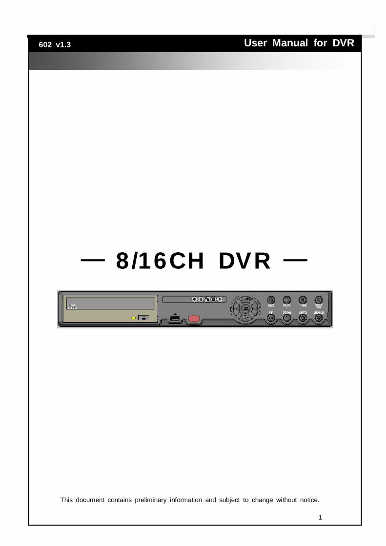
8/16CH DVR
User Manual for DVR
602 v1.3
This document contains preliminary information and subject to change without notice.

2
This symbol is intended to alert the user to the presence of unprotected “Dangerous voltage" within the product's enclosure that may be strong enough to cause a risk of electric shock.
This symbol is intended to alert the user to the presence of important operating and maintenance (servicing) instructions in the literature accompanying the appliance.
WARNING TO REDUCE THE RISK OF FIRE OR ELECTRIC SHOCK, DO NOT EXPOSE THIS APPLIANCE TO RAIN OR MOISTURE.
NOTE: This equipment has been tested and found to comply with the limits for a class digital device, pursuant to part 15 of the FCC Rules. These limits are designed to provide reasonable protection against harmful interference when the equipment is operated in a commercial environment. This equipment generates, uses, and can radiate radio frequency energy and, if not installed and used in accordance with the instruction manual, may cause harmful interference to radio communications. Operation of this equipment in a residential area is likely to cause harmful interference in which case the user will be required to correct the interference at his own expense.
Disposal of Old Electrical & Electronic Equipment (Applicable in the European Union and other European countries with separate collection systems)
This symbol on the product or on its packaging indicates that this product shall not be treated as household waste. Instead it shall be handed over to the applicable collection point for the recycling of electrical and electronic equipment. By ensuring this product is disposed of correctly, you will help prevent potential negative consequences for the environment and human health, which could otherwise be caused by inappropriate waste handling of this product. The recycling of materials will help to conserve natural resources. For more detailed information about recycling of this product, please contact your local city office, your household waste disposal service or the shop where you purchased the product.
3
Contents
CHAPTER 1 FEATURES ____________________________________________________5 CHAPTER 2 PACKING DETAIL AND INSTALLATION __________________________7
2-1 PACKING____________________________________________________________7 2-2 HARD DISK INSTALATION______________________________________________8 2-3 CD-RW INSTALATION_________________________________________________9
CHAPTER 3 LOCATION AND CONTROL _____________________________________11 3-1 FRONT PANEL CONTROLS____________________________________________11 3-2 REAR PANEL CONNECTORS __________________________________________12
CHAPTER 4 LIVE, PLAYBACK AND PTZ OPERATIONS ______________________13 4-1 LIVE Mode _________________________________________________________13 4-2 PLAYBACK Mode ____________________________________________________17 4-3 PTZ Mode __________________________________________________________19
CHAPTER 5 SETTING UP THE DVR_________________________________________21 5-1 RECORD SETUP____________________________________________________22 5-2 EVENT SETUP _____________________________________________________23
5-2.1 MOTION SETUP _______________________________________________23 5-2.1.1 MOTION AREA SETUP _____________________________________24 5-2.1.2 MOTION TIMER SETUP ___________________________________25
5-2.2 SENSOR SETUP_______________________________________________26 5-2.2.1 SENSOR TIMER SETUP ___________________________________26
5-3 TIMER SETUP ______________________________________________________27 5-4 CAMERA SETUP____________________________________________________27 5-5 PASSWORD SETUP _________________________________________________28 5-6 NETWORKING SETUP _______________________________________________29
5-6.1 ACCOUNT SETUP _____________________________________________31 5-6.2 APPLICATION SETUP __________________________________________32
5-6.2.1 DDNS SETUP ____________________________________________33 5-6.2.2 MAIL SETUP _____________________________________________35 5-6.2.3 MOBILE SETUP __________________________________________35
5-7 PTZ & 485 SETUP __________________________________________________36 5-8 SYSTEM SETUP ____________________________________________________37
5-8.1 DISPLAY SETUP_______________________________________________37 5-8.2 DATE/TIME SETUP_____________________________________________38 5-8.3 BUZZER & RELAY SETUP ______________________________________39 5-8.4 SPOT ________________________________________________________39
5-9 UTILITY SETUP_____________________________________________________40 5-9.1 HDD INITIALIZATION ___________________________________________40 5-9.2 USB INITIALIZATION ___________________________________________41 5-9.3 SYSTEM RECOVERY___________________________________________41 5-9.4 COPY CONFIG TO USB ________________________________________42 5-9.5 DOWNLOAD CONFIG FROM USB________________________________42 5-9.6 UPGRADE ____________________________________________________43
5-10 DIAGNOSTIC ______________________________________________________44 CHAPTER 6 BACKUP & SEARCH___________________________________________45
6-1 BACKUP SETUP ____________________________________________________45 6-2 SEARCH SETUP ____________________________________________________46
6-2.1 EVENT SEARCH_______________________________________________47 6-2.2 SEGMENT SEARCH ____________________________________________48 6-2.3 TIME SEARCH ________________________________________________48
4
CHAPTER 7 NETWORK SURVEILLANCE_____________________________________49
7-1 IE BROWSER SETUP _______________________________________________49 7-2 LIVE MODE ________________________________________________________51 7-3 PLAYBACK MODE___________________________________________________52 7-4 REMOTE SETUP MODE _____________________________________________53 7-5 EVENT LOG________________________________________________________54 7-6 REMOTE PLAYBACK ________________________________________________55
CHAPTER 8 SPECIFICATIONS ______________________________________________57 APPENDIX I MOBILE APPLICATION INSTALLATION AND USAGE GUIDE ________59
I-1 MOBILE APPLICATION INSTALLATION___________________________________59 I-2 MOBILE APPLICATION OPERATIONS___________________________________60
I-2.1 ADDING A DVR ________________________________________________60 I-2.2 LOGGING ONTO THE DVR ______________________________________61 I-2.3 MODIFYING A DVR’S LOGIN INFORMATION _______________________62 I-2.4 DELETING A DVR ______________________________________________62
I-3 LIVE VIEWING OPERATIONS__________________________________________63 I-3.1 SINGLE CHANNEL VIEWING _____________________________________63 I-3.2 STATUS BAR ___________________________________________________64 I-3.3 ALARM ________________________________________________________64 I-3.4 FULL SCREEN DISPLAY__________________________________________64
APPENDIX II CMS INSTALLATION AND USAGE GUIDE________________________65 Ⅱ-1 CMS INSTALLATION _________________________________________________65 Ⅱ-2 CMS LOGIN AND ENVIRONMENT______________________________________67 Ⅱ-3 DVRs, Groups and Events____________________________________________68 Ⅱ-3.1 View DVR/Group List __________________________________________68 Ⅱ-3.2 View Event Logs _______________________________________________69
Ⅱ-4 Local Information Display and Control ____________________________________69 Ⅱ-5 Main Display________________________________________________________70 Ⅱ-5.1 Audio Control __________________________________________________70 Ⅱ-5.2 eMap Display __________________________________________________71 Ⅱ-5.3 PTZ Control ___________________________________________________71
Ⅱ-6 Functions Bar _______________________________________________________71 Ⅱ-6.1 User Administration _____________________________________________72 Ⅱ-6.2 DVR Administration _____________________________________________73 Ⅱ-6.3 Group Administration ____________________________________________73 Ⅱ-6.4 eMap Administration ____________________________________________74 Ⅱ-6.5 Remote Play __________________________________________________75 Ⅱ-6.6 HDD Play _____________________________________________________76 Ⅱ-6.7 File Play ______________________________________________________76 Ⅱ-6.8 Event Play ____________________________________________________77 Ⅱ-6.9 Snapshot _____________________________________________________78 Ⅱ-6.10 Record ______________________________________________________78
APPENDIX Ⅲ DB 26 DEFINITION ____________________________________________79
5
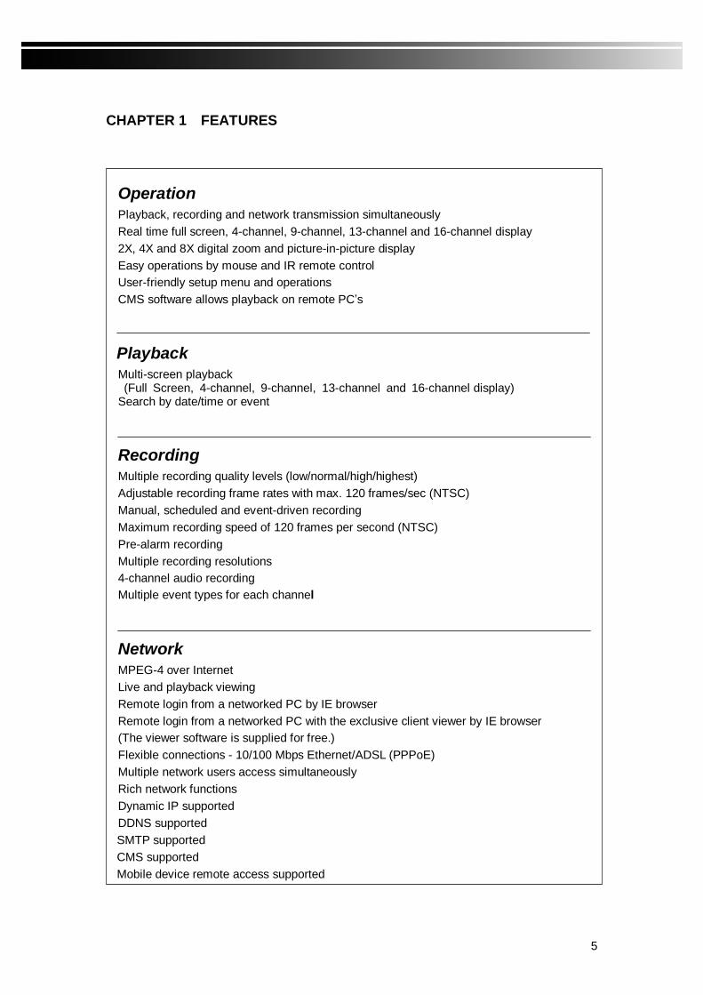
CHAPTER 1 FEATURES
Operation Playback, recording and network transmission simultaneously Real time full screen, 4-channel, 9-channel, 13-channel and 16-channel display 2X, 4X and 8X digital zoom and picture-in-picture display Easy operations by mouse and IR remote control User-friendly setup menu and operations CMS software allows playback on remote PC’s
Playback Multi-screen playback (Full Screen, 4-channel, 9-channel, 13-channel and 16-channel display) Search by date/time or event
Recording Multiple recording quality levels (low/normal/high/highest) Adjustable recording frame rates with max. 120 frames/sec (NTSC) Manual, scheduled and event-driven recording Maximum recording speed of 120 frames per second (NTSC) Pre-alarm recording Multiple recording resolutions 4-channel audio recording Multiple event types for each channel
Network MPEG-4 over Internet Live and playback viewing Remote login from a networked PC by IE browser Remote login from a networked PC with the exclusive client viewer by IE browser (The viewer software is supplied for free.) Flexible connections - 10/100 Mbps Ethernet/ADSL (PPPoE) Multiple network users access simultaneously Rich network functions Dynamic IP supported DDNS supported SMTP supported CMS supported Mobile device remote access supported

6
External storage Multiple external SATA hard disks supported
Audio 4-channels audio recording in real time
Backup USB external storage device CD-RW/ DVD±RW (optional)
PTZ Pelco-P, Pelco-D, KND, LI-LIN protocols supported
General Manual switch between PAL and NTSC Built-in hardware WATCHDOG Multiple languages support (English, Chinese, Spanish, Italian, Portuguese, Greek and Japanese)
Optional A pair of 8-DVR remote controls CD-RW/ DVD±RW VGA output for CRT/LCD monitor

7
CHAPTER 2 PACKING DETAIL AND INSTALLATION
2-1 PACKING
1. DVR
3. IR Remote control
5. Hard Disk Mount
9. Power Cord
4. SATA Cord x 2
2. Quick Start
10. Batteries
8. Power Adapter
6. 20 Screws 7. DB 26 Flat Cables
11. IDE Flat Cables
8
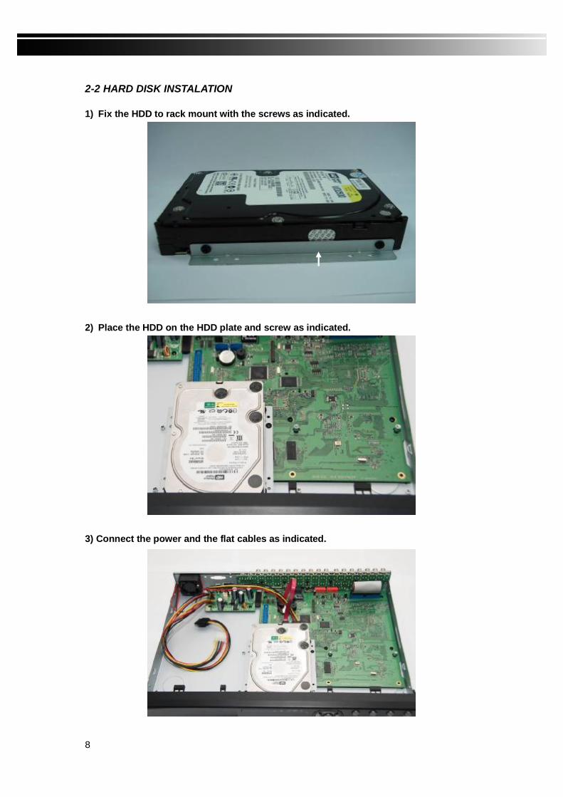
2-2 HARD DISK INSTALATION
1) Fix the HDD to rack mount with the screws as indicated.
2) Place the HDD on the HDD plate and screw as indicated.
3) Connect the power and the flat cables as indicated.
9
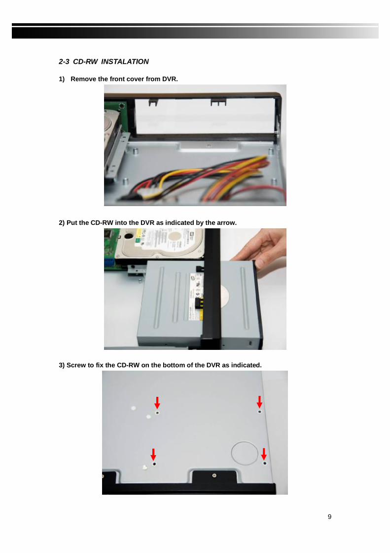
2-3 CD-RW INSTALATION 1) Remove the front cover from DVR.
2) Put the CD-RW into the DVR as indicated by the arrow.
3) Screw to fix the CD-RW on the bottom of the DVR as indicated.

10
4) Connect the power and the flat cables.
11
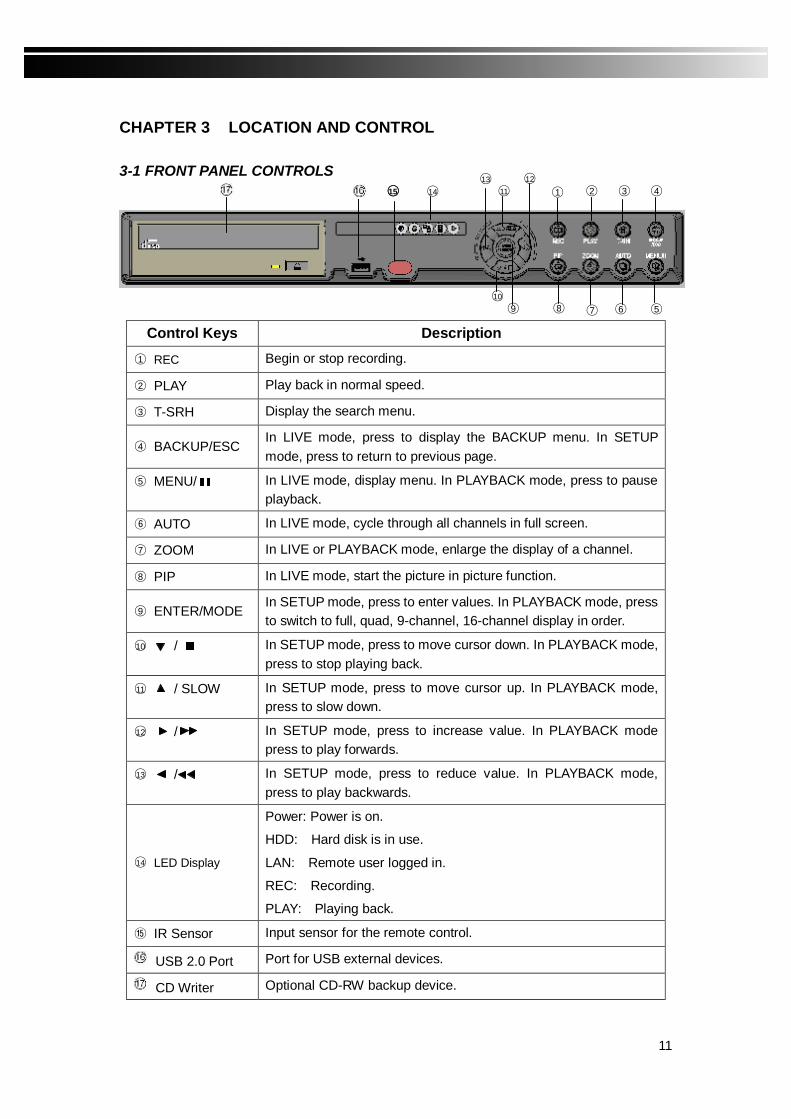
CHAPTER 3 LOCATION AND CONTROL 3-1 FRONT PANEL CONTROLS
Control Keys Description
1 REC Begin or stop recording.
2 PLAY Play back in normal speed.
3 T-SRH Display the search menu.
4 BACKUP/ESC In LIVE mode, press to display the BACKUP menu. In SETUP mode, press to return to previous page.
5 MENU/ In LIVE mode, display menu. In PLAYBACK mode, press to pause playback.
⑥ AUTO In LIVE mode, cycle through all channels in full screen.
7 ZOOM In LIVE or PLAYBACK mode, enlarge the display of a channel.
8 PIP In LIVE mode, start the picture in picture function.
9 ENTER/MODE In SETUP mode, press to enter values. In PLAYBACK mode, press to switch to full, quad, 9-channel, 16-channel display in order.
10 / In SETUP mode, press to move cursor down. In PLAYBACK mode, press to stop playing back.
11 / SLOW In SETUP mode, press to move cursor up. In PLAYBACK mode, press to slow down.
12 / In SETUP mode, press to increase value. In PLAYBACK mode press to play forwards.
13 / In SETUP mode, press to reduce value. In PLAYBACK mode, press to play backwards.
14 LED Display
Power: Power is on.
HDD: Hard disk is in use.
LAN: Remote user logged in.
REC: Recording.
PLAY: Playing back.
⑮ IR Sensor Input sensor for the remote control.
USB 2.0 Port Port for USB external devices.
CD Writer Optional CD-RW backup device.
4
6 7 8 10 9
11 1 2 3
5
13
15 14
8
12

12
3-2 REAR PANEL CONNECTORS
1 MAIN monitor BNC port for the main monitor.
2 SPOT monitor BNC port to display full screen video of all installed cameras in sequence.
3 VIDEO IN BNC input ports for cameras, 16 in total.
4 AUDIO IN RCA input port for audio signal.
5 VGA VGA port.
6 Fan DC 12V 40mm X 40mm fan.
7 DC 12V Socket for a DC 12V input.
8 POWER Power switch.
9 EXTERNAL I/O EXTERNAL I/O port for DB 26 flat cables.
Please refer to ‘Appendix III DB 26 Definition’.
10 USB 2.0 Port USB port.
11 LAN Network port.
12 E-SATA External SATA hard disks port.
⑬ 75Ω 75 ohm terminal switch.
⑭ AUDIO OUT RCA output for audio signal.
⑮ NTSC/PAL Switch Switch between NTSC and PAL format.
LOOP OUT BNC connectors to loop out the video input.
2 4 5
6
7 8 9 10 11 12
1 ③
⑬ ⑭ ⑮
16

13
CHAPTER 4 LIVE, PLAYBACK AND PTZ OPERATIONS This chapter describes the functions of the IR remote control and the mouse under three different modes: LIVE, PLAYBACK and PTZ. 4-1 LIVE Mode
Figure 4-1.1, shows a 16-channel display under the LIVE mode. Table 4-1.1 describes the remote control functions under the LIVE mode. Table 4-1.2 describes the mouse functions under the LIVE mode. Table 4-1.3 describes the graphical icons that may show under the LIVE mode.
Figure 4-1.1 Table 4-1.1 Remote control functions under the LIVE mode
Button Description
LOCK Enable/Disable the function of the buttons on the front panel, the remote control and the mouse.
MUTE Enable/Disable MUTE.
REC Start/Stop recording.
PLAY Start playing back the most recently recorded segment.
T-SRH Enter Search menu.
1,2…….7,8,9 Select the channel to monitor in full screen from channel 1 to 9.
+10 Select the channel to monitor in full screen from channel 10 to 16.
14
ENTER Switch to full screen, quad, 9-channel, 13-channel, or 16-channel display.
MENU Display Setup menu.
BK-UP/ESC Display Backup menu.
Switch to quad display.
Switch to 9-channel display.
Switch to 13-channel display.
Switch to 16-channel display.
STATUS Display Status.
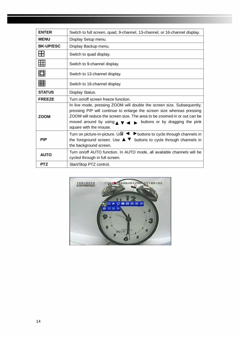
FREEZE Turn on/off screen freeze function.
ZOOM
In live mode, pressing ZOOM will double the screen size. Subsequently, pressing PIP will continue to enlarge the screen size whereas pressing ZOOM will reduce the screen size. The area to be zoomed in or out can be moved around by using buttons or by dragging the pink square with the mouse.
PIP Turn on picture-in-picture. Use buttons to cycle through channels in the foreground screen. Use buttons to cycle through channels in the background screen.
AUTO Turn on/off AUTO function. In AUTO mode, all available channels will be cycled through in full screen.
PTZ Start/Stop PTZ control.

15
Table 4-1.2 In LIVE mode, pressing the right button on mouse will bring up the graphical icons whose function is described below
Icon Description
Resting the mouse on this icon will bring up the following four menu icons.
Main menu.
Search menu.
Backup menu.
PTZ menu.
Turn on/off recording.
Playback.
Resting the mouse on this icon will bring up the following five display icons.
FREEZE.
PIP.
ZOOM.
AUTO.
LOCK.
Full screen display.
Quad display.
9-channel display.
13-channel display.
16-channel display.

16
Table 4-1.3 Description of graphical icons in LIVE mode
Icon Description
Frames/second for recording.
Recording is on.
Audio is on.
Motion detected on the channel.
Sensor detected on the channel.
Video loss detected on the channel.
USB device detected.
Remote user currently logged into DVR.
Timer recording is on. Yellow: Timer is set and recording has started. Green: Timer is set but recording has not started.
AUTO is on.
ZOOM is on.
FREEZE is on. Screen is frozen.
PIP is on.
LOCK is on.
PTZ control is on.

17
4-2 PLAYBACK Mode Figure 4-2.1 shows a 16-channel display under the PLAYBACK mode. Table 4-2.1 describes remote control functions under the PLAYBACK mode. Table 4-2.2 describes the mouse functions under the PLAYBACK mode.
Figure 4-2.1 Table 4-2.1 Remote control functions under the PLAYBACK mode
Button Description ENTER / MODE Switch to full screen, quad, 9-channel or 16-channel display. MENU / Turn on/off PAUSE. PLAY Play back at normal speed. / SLOW Play back at slower speed. Each press of the button slows down the
playback speed by 1/2; with the slowest being 1/16 of the normal speed. Current playback speed is shown in the upper right corner.
/ Fast rewind. Each press increases the speed to the next level. There are four speeds: 4X, 8X, 32X and 128X.
/ Fast forward. Each press increases the speed to the next level. There are four speeds: 4X, 8X, 32X and 128X.
/ Stop playback.

18
Table 4-2.1 In PLAYBACK mode, pressing the right button on mouse will bring up the graphical icons whose function is described below
圖示 說明
Fast rewind.
Pause.
Stop playback.
Play back in normal speed.
Fast forward.
Full screen display.
Quad display.
9-channel display.
16-channel display.

19
4-3 PTZ Mode To control PTZ, enter the PTZ mode from the LIVE mode. The PTZ icon will appear on top of the screen as shown in Figure 4-3.1. Table 4-3.2 describes the PTZ control functions.
Figure 4-3.1
20
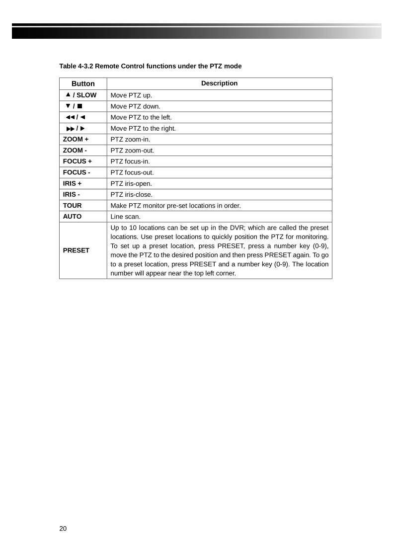
Table 4-3.2 Remote Control functions under the PTZ mode
Button Description
/ SLOW Move PTZ up. / Move PTZ down. / Move PTZ to the left. / Move PTZ to the right. ZOOM + PTZ zoom-in. ZOOM - PTZ zoom-out. FOCUS + PTZ focus-in. FOCUS - PTZ focus-out. IRIS + PTZ iris-open. IRIS - PTZ iris-close. TOUR Make PTZ monitor pre-set locations in order. AUTO Line scan.
PRESET
Up to 10 locations can be set up in the DVR; which are called the preset locations. Use preset locations to quickly position the PTZ for monitoring. To set up a preset location, press PRESET, press a number key (0-9), move the PTZ to the desired position and then press PRESET again. To go to a preset location, press PRESET and a number key (0-9). The location number will appear near the top left corner.

21
CHAPTER 5 SETTING UP THE DVR To set up the DVR, a valid administrator’s password must be entered. The first time the DVR is started up, the default password, ‘00000’, must be entered. An administrator’s password should be set up as part of the initial setup process and used thereafter to set up the DVR. Please refer to section 5-5 Password Setup.
There are three ways to bring up the main setup menu as summarized below.
Use Description
Front Panel
1. Press the MENU button on the front panel. 2. Use to change the value of password and to move the cursor.
Press ENTER when done.
Remote Control
1. Press the MENU button. 2. Press number buttons to enter the password. When the last digit of a correct
password is entered the main menu will show up.
Mouse 1. Press the right button to show command icons. Select with the left
button. 2. Click the arrow at the cursor, scroll the wheel to change values. When done,
click left button to bring up the main menu.
When the main menu appears, click left mouse button or use keys to move the cursor, then press ENTER to select a setup option.

22
Table 5-0.1 Remote control functions for the setup menu.
Button Description Switch to various selections in an option. Switch to various options. MENU Save setup values and return to LIVE display. BK-UP / ESC Save setup values and return to previous menu. ENTER Enter a menu or show on-screen keyboard. PLAY Activate setup values.
5-1 RECORD SETUP
Item Description
RESOLUTION NTSC: Available resolutions are 720X240 and 360X240.
PAL: Available resolutions are 720X288 and 360X288.
EVENT RECORD For event-driven recording, select MOTION, SENSOR or both to trigger recording; or OFF to disable event recording.
HDD FULL When HDD is full select STOP to stop recording or OVERWRITE to reuse the HDD.
PRE-ALARM RECORD Enable/Disable pre-event recording. Pre-event recording time is 10 seconds.
AUDIO RECORD Enable/Disable audio recording.
WATERMARK Enable/Disable WATERMARK.
QUALITY For normal and event-driven recording, select the recording quality from LOW, NORMAL, HIGH, and HIGHEST.
FRAME RATE
Select maximum recording frame rate shared by all channels.
NTSC(720X240):4, 10, 20, 30, 60.
NTSC(360X240):8, 20, 40, 60, 120.
PAL(720X288):3, 6, 12, 25, 50.
PAL(360X288):6, 12, 24, 50, 100.
23
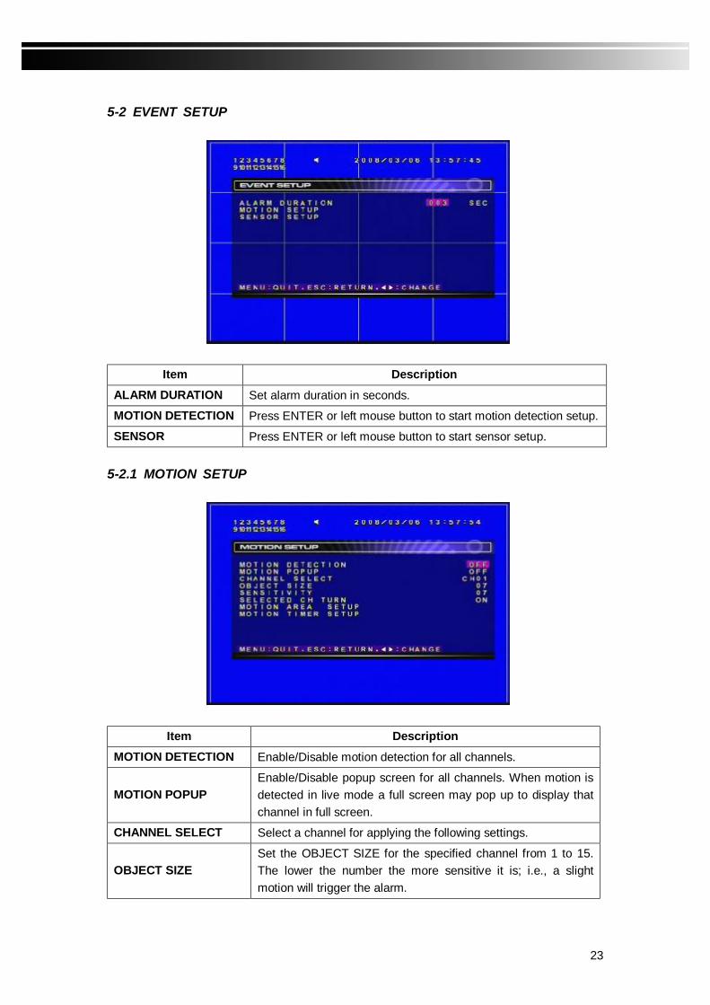
5-2 EVENT SETUP
Item Description ALARM DURATION Set alarm duration in seconds.
MOTION DETECTION Press ENTER or left mouse button to start motion detection setup.
SENSOR Press ENTER or left mouse button to start sensor setup. 5-2.1 MOTION SETUP
Item Description MOTION DETECTION Enable/Disable motion detection for all channels.
MOTION POPUP Enable/Disable popup screen for all channels. When motion is detected in live mode a full screen may pop up to display that channel in full screen.
CHANNEL SELECT Select a channel for applying the following settings.
OBJECT SIZE Set the OBJECT SIZE for the specified channel from 1 to 15. The lower the number the more sensitive it is; i.e., a slight motion will trigger the alarm.
24
SENSITIVITY Set the SENSITIVITY for the specified channel from 1 to 15. The lower the number the more sensitive it is.
SELECTED CH TURN Enable/Disable above selected channel for motion detection.
MOTION AREA SETUP Press ENTER or left mouse button to set up motion detection areas on the screen.
MOTION TIMER SETUP Press ENTER or left mouse button to set up time periods for motion detection.
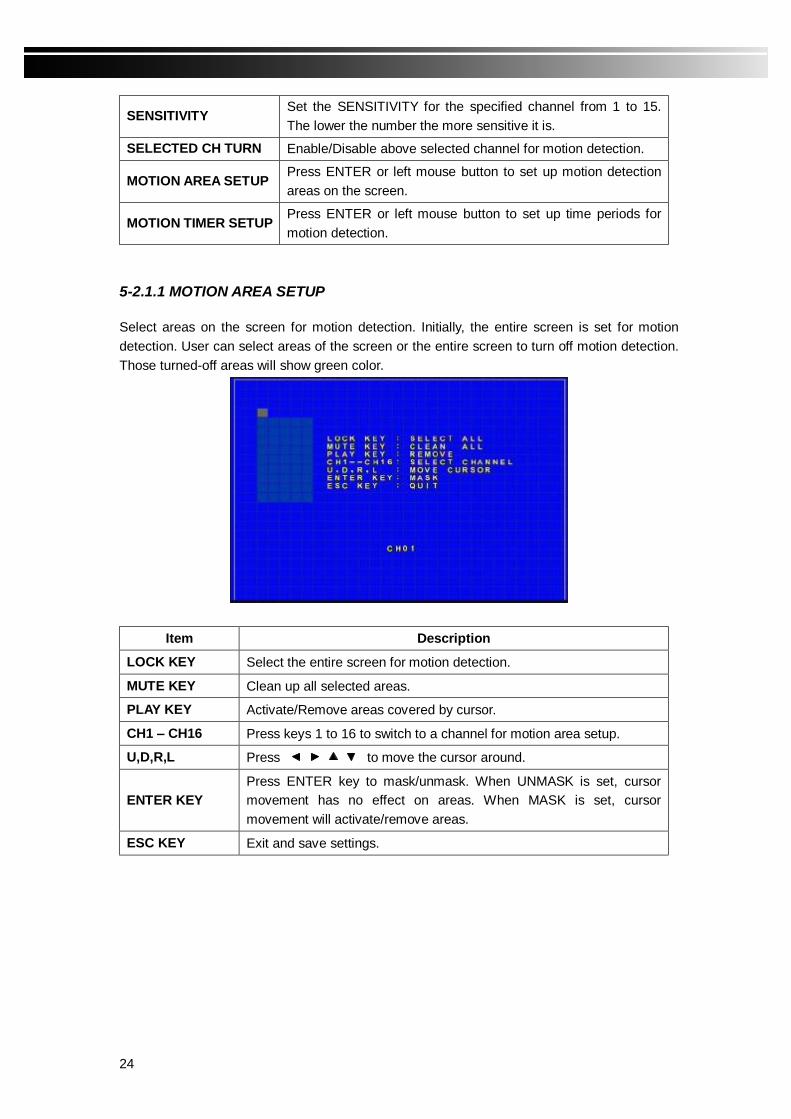
5-2.1.1 MOTION AREA SETUP Select areas on the screen for motion detection. Initially, the entire screen is set for motion detection. User can select areas of the screen or the entire screen to turn off motion detection. Those turned-off areas will show green color.
Item Description
LOCK KEY Select the entire screen for motion detection.
MUTE KEY Clean up all selected areas.
PLAY KEY Activate/Remove areas covered by cursor.
CH1 – CH16 Press keys 1 to 16 to switch to a channel for motion area setup.
U,D,R,L Press to move the cursor around.
ENTER KEY Press ENTER key to mask/unmask. When UNMASK is set, cursor movement has no effect on areas. When MASK is set, cursor movement will activate/remove areas.
ESC KEY Exit and save settings.
25
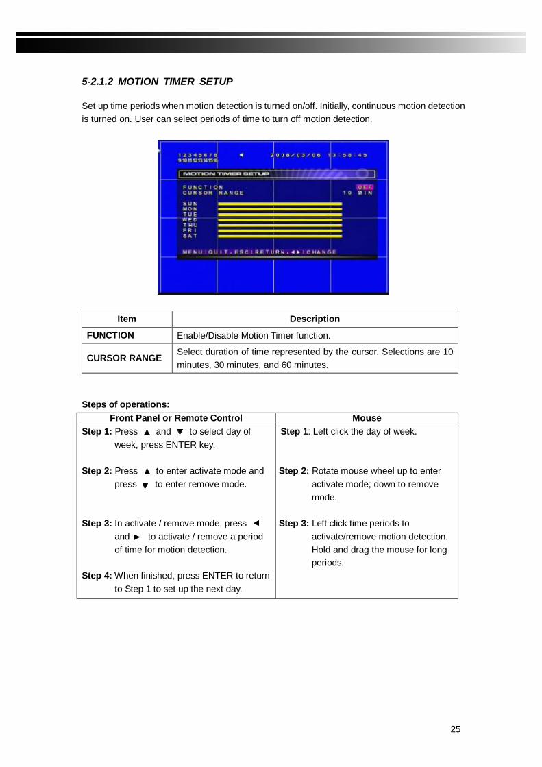
5-2.1.2 MOTION TIMER SETUP Set up time periods when motion detection is turned on/off. Initially, continuous motion detection is turned on. User can select periods of time to turn off motion detection.
Item Description
FUNCTION Enable/Disable Motion Timer function.
CURSOR RANGE Select duration of time represented by the cursor. Selections are 10 minutes, 30 minutes, and 60 minutes.
Steps of operations:
Front Panel or Remote Control Mouse Step 1: Press and to select day of
week, press ENTER key. Step 2: Press to enter activate mode and
press to enter remove mode. Step 3: In activate / remove mode, press
and to activate / remove a period of time for motion detection.
Step 4: When finished, press ENTER to return
to Step 1 to set up the next day.
Step 1: Left click the day of week. Step 2: Rotate mouse wheel up to enter
activate mode; down to remove mode.
Step 3: Left click time periods to
activate/remove motion detection. Hold and drag the mouse for long periods.

26
5-2.2 SENSOR SETUP
Item Description
SENSOR DETECTION Enable/Disable sensor detection.
SENSOR POPUP Enable/Disable popup screen. When sensor is triggered in live mode a full screen may pop up to display that channel.
SENSOR POLARITY SETUP
Select groups of sensors to apply voltage settings. Sensors are displayed in two groups with 8 sensors in each group.
SENSOR 01- 16 For the sensor to trigger, set the type of voltage (low or high) expected at the SENSOR IN connectors.
5-2.2.1 SENSOR TIMER SETUP
Set up time periods when the sensor function is turned on/off. For operations, please refer to 5-2.1.2 MOTION TIMER SETUP

27
5-3 TIMER SETUP Set up time periods when the recording function is turned on/off. For operations, please refer to 5-2.1.2 MOTION TIMER SETUP.
5-4 CAMERA SETUP
Item Description
CHANNEL SELECT Select the channel for applying the following settings.
BRIGHTNESS Change the BRIGHTNESS value for the specified channel. Values range from 1 to 64, default is 32.
CONTRAST Change the CONTRAST value for the specified channel. Values range from 1 to 64, default is 32.
SATURATION Change the SATURATION value for the specified channel. Values range from 1 to 64, default is 32.
HUE Change the HUE value for the specified channel. Values range from 1 to 64, default is 32. PAL systems do not have this function.
RECORD Enable/Disable recording for the specified channel.
NAME Enter a new name for the specified channel.
MASK Specific channels can be blocked from viewing. To block a channel, turn MASK on for the specific channel. The blocked channels will show a blue screen.

28
5-5 PASSWORD SETUP
Item Description After 1 minute of idling, DVR will automatically exit setup and enter LIVE mode, except when it’s playing back. For security reasons, the user may be logged out and further key entries may be ignored, depending on the AUTO KEYLOCK setup.
Function Setting Logout1 Key Lock2
KEY LOCK O O KEY UNLOCK O X
AUTO LOCK
DISABLE X X ADMIN, USER1, USER2, USER3, USER4.
Enter passwords. Press ENTER to enter values one digit at a time. Only numerical digits can be used.
Note 1: If the system is “idled-out”, only basic operations are allowed, such as FREEZE, PIP,
ZOOM, AUTO, etc. Other operations require entering a password. Note 2: When keys are locked, the DVR will not react to the remote control or mouse without
the password being entered first. Note 3: ‘O’ means actions DVR will take. ‘X’ means actions DVR will not take.

29
5-6 NETWORKING SETUP The DVR can be browsed/managed by remote clients over the network. There are three ways to configure the DVR for networking. If the settings are subsequently changed, the PLAY button should be pressed to re-connect the DVR using the new settings. If a router is used to connect the DVR to the network then it should be updated to reflect the change. DHCP If the DHCP option is used to connect the DVR to a network, an IP address is assigned by the DHCP server automatically.
Item Description FUNCTION Enable/Disable network function.
ACCOUNT Press ENTER to enter ACCOUNT setup.
APPLICATIONS Press ENTER to enter APPLICATIONS setup.
PORT The port number used by the DVR for network connections from remote clients; including PC’s through IE browser, cell phones, PDA’s, etc. A valid port number ranges from 1 to 65535.
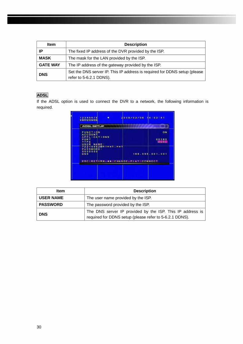
TYPE Select a type of network connection (DHCP, LAN, or ADSL). LAN If the LAN option is used to connect the DVR to a network the following information is required.
30
Item Description IP The fixed IP address of the DVR provided by the ISP. MASK The mask for the LAN provided by the ISP. GATE WAY The IP address of the gateway provided by the ISP.
DNS Set the DNS server IP. This IP address is required for DDNS setup (please refer to 5-6.2.1 DDNS).
ADSL If the ADSL option is used to connect the DVR to a network, the following information is required.
Item Description USER NAME The user name provided by the ISP. PASSWORD The password provided by the ISP.
DNS The DNS server IP provided by the ISP. This IP address is required for DDNS setup (please refer to 5-6.2.1 DDNS).
31
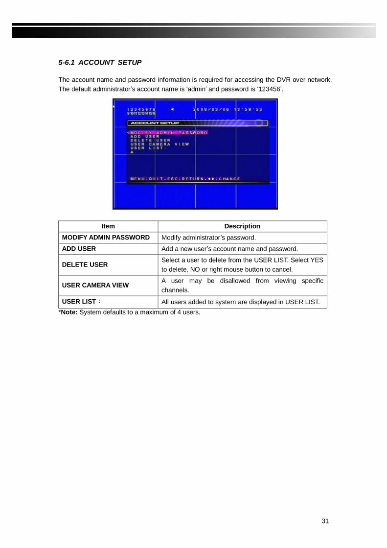
5-6.1 ACCOUNT SETUP The account name and password information is required for accessing the DVR over network. The default administrator’s account name is ‘admin’ and password is ‘123456’.
Item Description MODIFY ADMIN PASSWORD Modify administrator’s password.
ADD USER Add a new user’s account name and password.
DELETE USER Select a user to delete from the USER LIST. Select YES to delete, NO or right mouse button to cancel.
USER CAMERA VIEW A user may be disallowed from viewing specific channels.
USER LIST: All users added to system are displayed in USER LIST. *Note: System defaults to a maximum of 4 users.
32
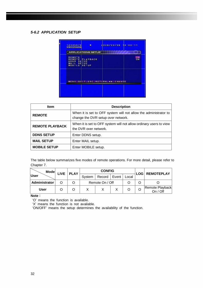
5-6.2 APPLICATION SETUP
Item Description
REMOTE When it is set to OFF system will not allow the administrator to change the DVR setup over network.
REMOTE PLAYBACK When it is set to OFF system will not allow ordinary users to view the DVR over network.
DDNS SETUP Enter DDNS setup.
MAIL SETUP Enter MAIL setup.
MOBILE SETUP Enter MOBILE setup. The table below summarizes five modes of remote operations. For more detail, please refer to Chapter 7.
CONFIG Mode User LIVE PLAY
System Record Event Local LOG REMOTEPLAY
Administrator O O Remote On / Off O O O
User O O X X X O O Remote Playback On / Off
Note: ‘O’ means the function is available. ‘X’ means the function is not available. ‘ON/OFF’ means the setup determines the availability of the function.

33
5-6.2.1 DDNS SETUP Please use one of the following websites to register DDNS: DYNDNS.ORG, NO-IP.ORG, CUSTOM.COM, I-DVR.NET (provided by manufacturer). After registration, DDNS setup information such as user name, password and host name will be provided. Please enter the information on this screen. Note that the PLAY button should be pressed to update the DDNS settings.
Item Description FUNCTION Enable/Disable DDNS function. SERVER Select registration SERVER. HOST Key in the HOST NAME. USER NAME Key in the USER NAME. PASSWORD Key in a PASSWORD.
DDNS Registration on I-DVR.NET
In the package of every DVR, there is a sticker that shows a pair of username and password that can be used to log into I-DVR.NET, which is maintained by the DVR manufacturer. To register DDNS on I-DVR.NET, follow the steps below.
Step 1. In IE browser, type in I-DVR.NET as the web address. Upon entering the website, a “Control Panel Logon” screen is shown. Enter the Username and password provided on the sticker in the “Email” and “Password” fields. Press “Logon” when done.
34
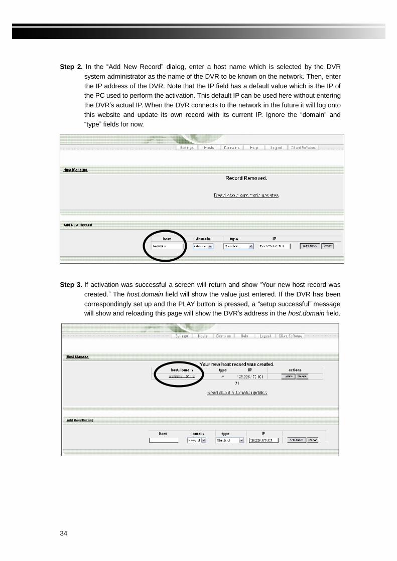
Step 2. In the “Add New Record” dialog, enter a host name which is selected by the DVR
system administrator as the name of the DVR to be known on the network. Then, enter the IP address of the DVR. Note that the IP field has a default value which is the IP of the PC used to perform the activation. This default IP can be used here without entering the DVR’s actual IP. When the DVR connects to the network in the future it will log onto this website and update its own record with its current IP. Ignore the “domain” and “type” fields for now.
Step 3. If activation was successful a screen will return and show “Your new host record was
created.” The host.domain field will show the value just entered. If the DVR has been correspondingly set up and the PLAY button is pressed, a “setup successful” message will show and reloading this page will show the DVR’s address in the host.domain field.

35
5-6.2.2 MAIL SETUP
E-mail can be used as a form of notification when an event occurs. (VLOSS、MOTION、SENSOR、REMOTEIN、REMOTEOUT、HDD FULL、KEY LOCK、KEY UNLOC,please refer to ‘6-2.1 EVENT SEARCH’)
When a MOTION or SENSOR alarm occurs an image will be sent along with the email message. The image is taken at the time the alarm occurred and is in AVI format.
Item Description FUNCTION Enable/Disable MAIL function.
SERVER Set MAIL server.
USER NAME Set log in MAIL Server’s user name.
PASSWORD Set log in MAIL Server’s password. EMAIL ADDRESS Set receiver’s email address.
5-6.2.3 MOBILE SETUP

36
Wireless mobile devices, such as cellular phones or PDA’s, can log onto the DVR and view live video through 3G or GPRS network. Users of the mobile devices should install customized software to connect to the DVR. Please refer to “APPENDIX I MOBILE APPLICATION INSTALLATION AND USAGE GUIDE”.
Item Description FUNCTION Enable/Disable MOBILE function.
PORT Port number used by the DVR for mobile connections. Valid port numbers are 1-65535.
5-7 PTZ & 485 SETUP In addition to the following settings, the 485 cable of the PTZ camera should be connected to the 485 port of the DVR to control the PTZ.
Item Description
PROTOCOL Select the protocol. Supported protocols are PELCO-P, PELCO-D, KND and LI-LIN.
BAUDRATE Select transmission speed: 2400, 4800, and 9600.
CHANNEL SELECT Select the channel for applying the settings.
PTZ ID Select the PTZ ID. Valid values are 1-64.
37
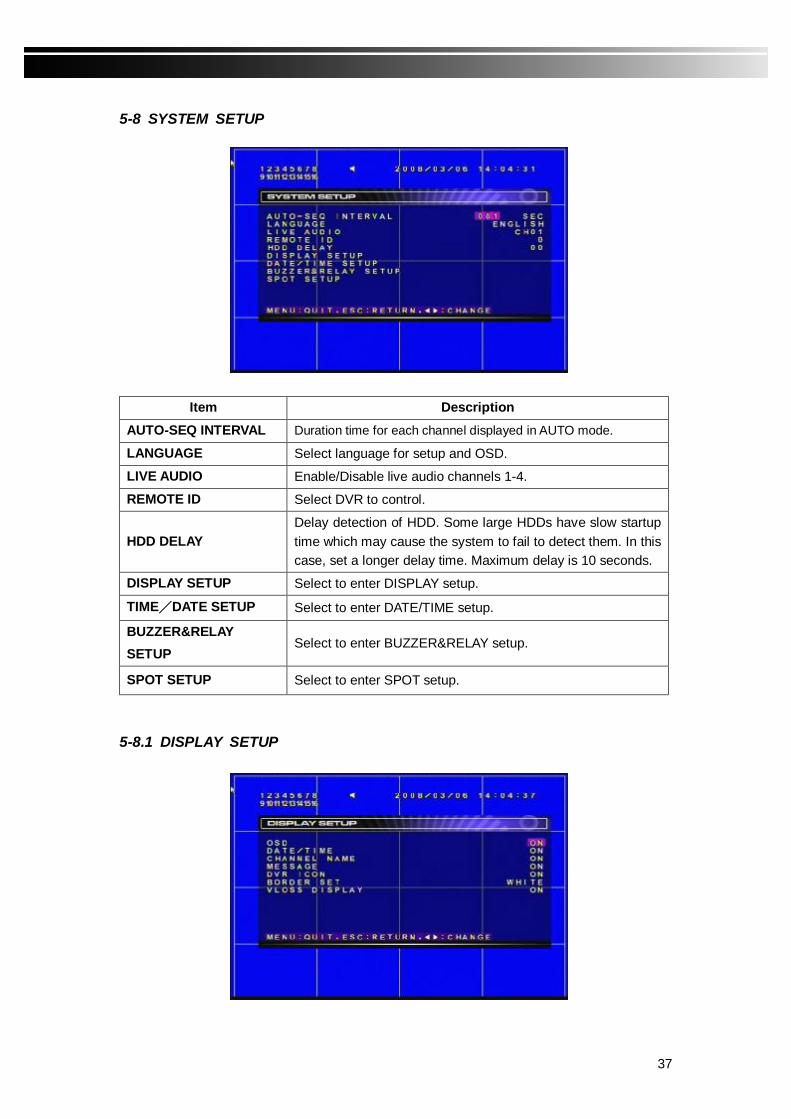
5-8 SYSTEM SETUP
Item Description AUTO-SEQ INTERVAL Duration time for each channel displayed in AUTO mode.
LANGUAGE Select language for setup and OSD.
LIVE AUDIO Enable/Disable live audio channels 1-4.
REMOTE ID Select DVR to control.
HDD DELAY Delay detection of HDD. Some large HDDs have slow startup time which may cause the system to fail to detect them. In this case, set a longer delay time. Maximum delay is 10 seconds.
DISPLAY SETUP Select to enter DISPLAY setup.
TIME/DATE SETUP Select to enter DATE/TIME setup.
BUZZER&RELAY SETUP
Select to enter BUZZER&RELAY setup.
SPOT SETUP Select to enter SPOT setup.
5-8.1 DISPLAY SETUP
38
Item Description OSD Enable/Disable OSD function.
DATE/TIME Enable/Disable DATE/TIME display.
CHANNEL NAME Enable/Disable CHANNEL NAME display
MESSAGE Enable/Disable MESSAGE display.
DVR ICON Enable/Disable DVR ICON display.
BORDER SET Set boarder color.
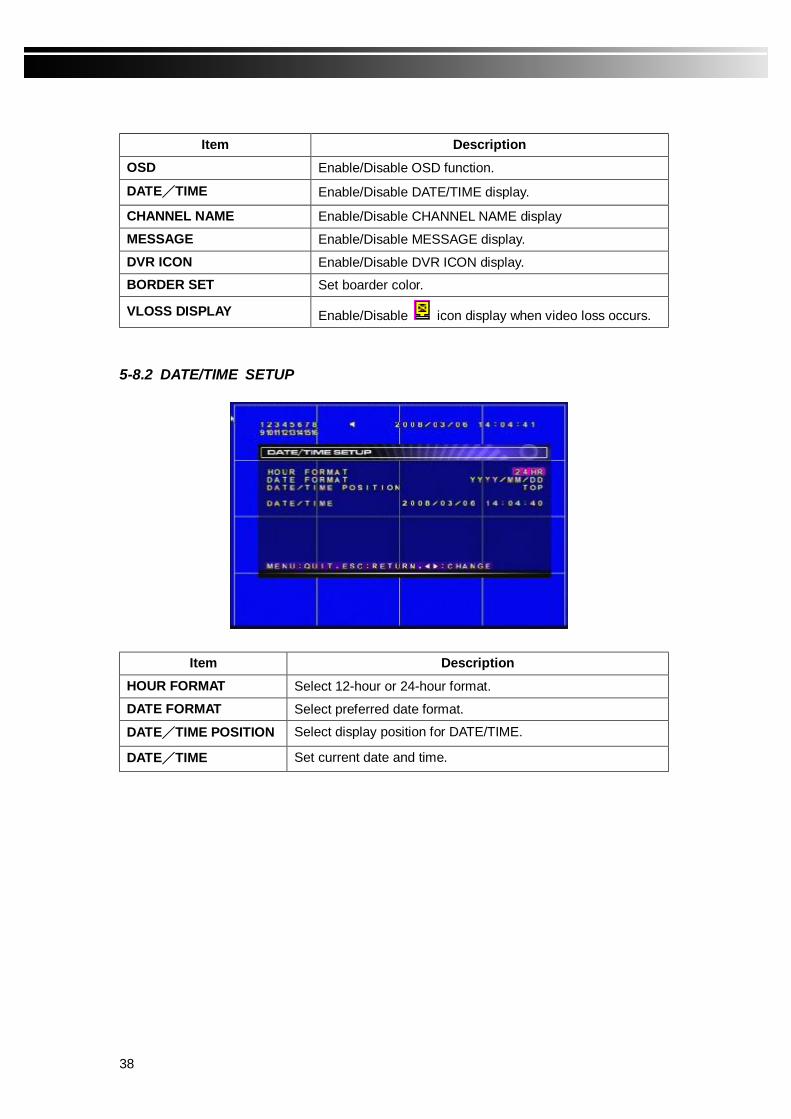
VLOSS DISPLAY Enable/Disable icon display when video loss occurs. 5-8.2 DATE/TIME SETUP
Item Description HOUR FORMAT Select 12-hour or 24-hour format.
DATE FORMAT Select preferred date format.
DATE/TIME POSITION Select display position for DATE/TIME.
DATE/TIME Set current date and time.

39
5-8.3 BUZZER & RELAY SETUP
Item Description KEY TONE Enable/Disable silent key strokes.
ALARM BUZZER Enable/Disable alarm buzzer when motion is detected, sensor is triggered or video loss occurs.
- SENSOR BUZZER The buzzer will sound when a sensor is triggered.
- MOTION BUZZER The buzzer will sound when motion is detected. - VLOSS BUZZER The buzzer will sound when video loss occurs.
ALARM RELAY Set relay signal to be Normal Close (N.C.) or Normal Open (N.O.). If an alarm occurred a signal will be sent to the RELAY OUT blocks.
- SENSOR RELAY When a sensor is triggered a relay signal will be sent. - MOTION RELAY When motion is detected a relay signal will be sent. - VLOSS RELAY When video loss occurs a relay signal will be sent.
5-8.4 SPOT
The DVR has two modes of video output; one is main video output, the other is spot video output. SPOT setup is for controlling the order of channels the system cycles through in SPOT mode. User can monitor every channel in the SPOT mode. Up to 20 channels can be set up to display in a certain order, including single channel display or quad display.

40
Item Description
SPOT MODE The order of channels or AUTO.。Options are SEQUENCE/MANUAL .
SPOT SEQ. The duration of each channel under SPOT mode.
GROUP SETUP Groups of 4 channels to be displayed in quad display. There are four groups in total.
5-9 UTILITY SETUP
Item Description
HDD INITIALIZATION Select to initialize hard disks.
USB INITIALIZATION Select to initialize USB storage device.
SYSTEM RECOVERY Select to restore default setup values.
COPY SETUP TO USB Select to copy setup values to a USB device.
DOWNLOAD SETUP FROM USB Select to download setup values from a USB device.
UPGRADE Select to upgrade firmware.
5-9.1 HDD INITIALIZATION This function will clean up all data on hard disks. Please stop recording before performing this function. Select ‘YES’ to clean up HDD. Press ESC on remote control, press mouse right button or select ‘NO’ to cancel this function.

41
5-9.2 USB INITIALIZATION
Press ENTER to clean up all data on USB storage device. Select ‘YES’ to clean up USB. Press ESC on remote control, press mouse right button or select ‘NO’ to cancel this function.
5-9.3 SYSTEM RECOVERY
Press ENTER to restore system default values. Select ‘YES’ to restore. Press ESC on remote control, press mouse right button or select ‘NO’ to cancel this function.
42
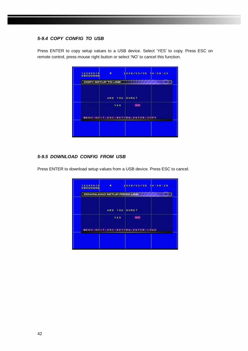
5-9.4 COPY CONFIG TO USB Press ENTER to copy setup values to a USB device. Select ‘YES’ to copy. Press ESC on remote control, press mouse right button or select ‘NO’ to cancel this function.
5-9.5 DOWNLOAD CONFIG FROM USB
Press ENTER to download setup values from a USB device. Press ESC to cancel.
43
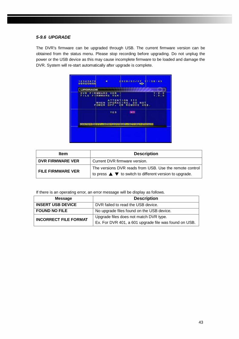
5-9.6 UPGRADE The DVR’s firmware can be upgraded through USB. The current firmware version can be obtained from the status menu. Please stop recording before upgrading. Do not unplug the power or the USB device as this may cause incomplete firmware to be loaded and damage the DVR. System will re-start automatically after upgrade is complete.
Item Description DVR FIRMWARE VER Current DVR firmware version.
FILE FIRMWARE VER The versions DVR reads from USB. Use the remote control to press to switch to different version to upgrade.
If there is an operating error, an error message will be display as follows.
Message Description INSERT USB DEVICE DVR failed to read the USB device. FOUND NO FILE No upgrade files found on the USB device.
INCORRECT FILE FORMAT Upgrade files does not match DVR type. Ex. For DVR 401, a 601 upgrade file was found on USB.

44
5-10 DIAGNOSTIC
Item Description VERSION The DVR’s current firmware version.
IP The DVR’s connected IP address. If disconnected from network, the screen will display ‘NETWORK DISCONNECT’.
MAC The DVR’s MAC address.
NO. HDD number. All detected HDDs will be listed here.
VOLUME HDD capacity.
USED Percentage of space used on HDD. ‘OW’ means HDD has started to overwrite (refer to 5-1 RECORDING SETUP).
PLACE HDD is internal or external.
STATUS
Shows HDD status.
USING means the HDD is being used for recording.
GOOD/BAD means the HDD has a known/unknown format to the DVR. A newly added HDD should be formatted by the DVR before being put to use (refer to 5-9.1 HDD INITIALIZATION).
FORMAT The latest format time of HDD.

45
CHAPTER 6 BACKUP & SEARCH 6-1 BACKUP SETUP User can create a backup of the data recorded in a specified time frame. To do so, either a built-in CD R/W must exist or some storage device must be connected to the USB port. The format of the backup can be either AVI or PES, which is determined by how the user foresees it to be played back in the future. If it is to be played back on a normal PC with Microsoft Media Player then AVI format should be selected and an AVI codec like Klcodec should be installed on the PC. Otherwise, the PES format should be selected. In this case, the IE browser should be used to connect to the DVR to play back the data. For more detail, please refer to 7-3 PLAYBACK MODE.
Item Description
BACKUP DEVICE Select CD R/W or USB as the backup device. The default size for CD R/W is 640 MB. Press the PLAY button to select a larger size.
BACKUP CHANNEL Select a backup channel or ALL to backup all channels.
TRANSFER TO AVI OFF: backup in PES format. ON: backup in AVI format.
START Select backup start time which should be after RECORD START.
END Select backup end time which should be before RECORD END.
BACKUP SIZE Backup file size / Backup device size, displayed by the DVR.
START BACKUP Press ENTER or left click START BACKUP to start backing up.
FIRST The start time of recorded data on HDD.
LAST The end time of recorded data on HDD.

46
6-2 SEARCH SETUP
Item Description EVENT SEARCH Select to start EVENT SEARCH.
SEGMENT SEARCH Select to start SEGMENT SEARCH.
TIME SEARCH Select to start TIME SEARCH.

47
6-2.1 EVENT SEARCH The DVR automatically records events with the time and channel information. If there is recording for an event it will be indicated in the INFO field next to channel number. Events are defined as follows, VLOSS = video loss, MOTION = motion detected, SENSOR = sensor triggered, REMOTEIN = user log-in over the network, REMOTEOUT = user log-out over the network. KEYLOCK = keys are locked, KEYUNLOCK = keys are unlocked.
Item Description DATE/TIME Date and time of the event.
Types of event. VLOSS Video loss.
MOTION Motion detected.
SENSOR Sensor triggered.
REMOTEIN User logged in through network.
REMOTEOUT User logged out through network.
POWER ON DVR powered on.
KEY LOCK DVR keys locked.
KEY UNLOCK DVR keys unlocked.
EVENT
HDD FULL Hard disk full.
INFO. Channel the event occurred. If there is recorded data, an icon,
, will be displayed.

48
6-2.2 SEGMENT SEARCH A list of recorded data segments will be displayed in units of one hour. If a segment is longer than one hour it will be broken down to hour-long segments. User can select a segment to play back by pressing and to move cursor up and down, and to change page. With the mouse, roll the wheel up and down to change page. Press ENTER or left click on a segment to start playing back.
6-2.3 TIME SEARCH
TIME SEARCH requires a date and a time to find the recorded data to play back. To specify a date, use keys to move the cursor up and down, use or roll the mouse wheel to change date. Press ENTER or left click the desired date. Note that dates with recorded data are surrounded by red borders.
After a date is selected, a new screen is displayed for selecting time. The digits on the left-hand side represent hours of the day in 24-hour format. Each row represents 60 minutes of the hour. Yellow portion means there is recording for that time segment; gray means there isn’t. Select a start time and system will start playing back.
49
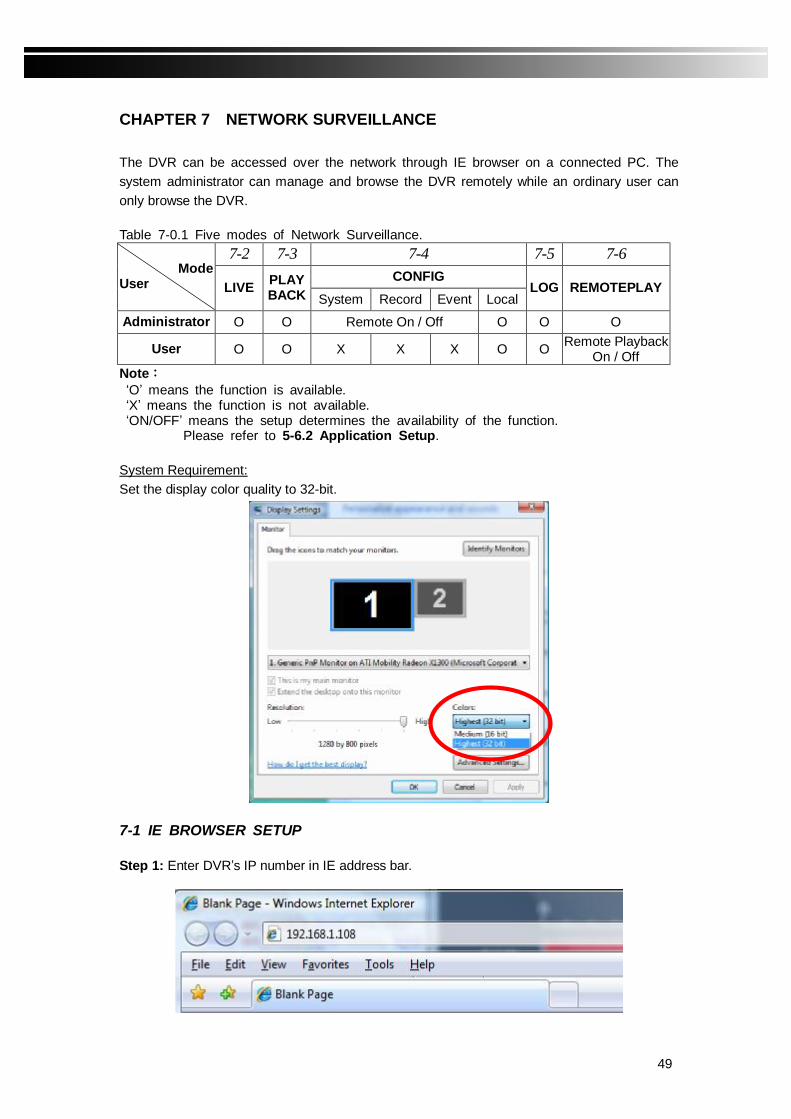
CHAPTER 7 NETWORK SURVEILLANCE The DVR can be accessed over the network through IE browser on a connected PC. The system administrator can manage and browse the DVR remotely while an ordinary user can only browse the DVR. Table 7-0.1 Five modes of Network Surveillance.
7-2 7-3 7-4 7-5 7-6
CONFIG Mode User LIVE PLAY
BACK System Record Event Local LOG REMOTEPLAY
Administrator O O Remote On / Off O O O
User O O X X X O O Remote Playback On / Off
Note: ‘O’ means the function is available. ‘X’ means the function is not available. ‘ON/OFF’ means the setup determines the availability of the function.
Please refer to 5-6.2 Application Setup. System Requirement: Set the display color quality to 32-bit.
7-1 IE BROWSER SETUP Step 1: Enter DVR’s IP number in IE address bar.

50
Step 2: A dialogue box will appear. Enter Administrator’s name and password. The default name is “admin” and password is “123456”. Please refer to 5-6.1 Account Setup for changing the defaults.
Step 3: If it’s the first time the user uses IE to access the DVR the system will show the following screen and ask for ActiveX Control installation. Select “Install ActiveX Control”. The system will spend a few minutes downloading and installing the ActiveX Controls.
After successful login, user will see a screen with a display area on the right, a control panel on the left, and a status bar at the bottom as shown below.

51
7-2 LIVE MODE While accessing the DVR remotely, use the control panel on the left hand side to control the
DVR. Pressing will display the live mode control panel as shown in figure 7-2.1. Clicking on the panel will issue commands to the remote DVR. Table 7-2.1 describes the live mode operations.
Figure 7-2.1
Table 7-2.1
Figure 7-2.2 shows the status bar of DVR in the IE browser. Initially, the channel numbers are displayed. If an event has been triggered an icon will be shown instead of the channel number, as shown in Figure 7-2.3. Table 7-2.2 describes the meaning of the icons.
Figure 7-2.2
Figure 7-2.3
Button Description
Channel 1 to 16.
Switch to full screen display for the selected channel.
Switch to quad mode.
Switch to 9-channel mode.
Switch to 16-channel mode.
Switch to audio channel 1-4 or turn off audio.
Start/Stop recording of live video to local storage.
Take a flash image. A dialogue will pop up to confirm and solicit a file path to store the image in.
Switch to full screen display.
First select a channel for operating PTZ. The DVR controls the PTZ camera to capture video image in 8 directions. If the PTZ camera cannot be controlled as preferred, check PTZ setup.
Zoom in on PTZ camera captured image.
Zoom out of PTZ camera captured image.

52
Item Description
Sensor alarm
Motion alarm
Video Loss alarm
Table 7-2.2 7-3 PLAYBACK MODE
Pressing on the control panel will display the playback mode control panel as shown in figure 7-3.1. Clicking on the panel will issue commands to the remote DVR. Table 7-3.1 describes the playback mode operations.
* Table 7-3.1
Button Description
Select a Channel to play back.
Open a backup file to play back. The data to be played back must already reside on local storage. A dialogue box will solicit a path to the file.
Start/Pause playback.
Fast rewind.
Fast forward.
Stop playback.
Take a flash image.
Figure 7-3.1

53
7-4 REMOTE SETUP MODE
Press to display the Remote Setup control panel as shown in figure 7-4.1. Table 7-4.1 and 7-4.2 describe the operations.
Table 7-4.1
Figure 7-4.1
Local Setup Description
EVENT RECORD Enable/Disable local recording when an event is triggered on the remote DVR.
OSD DISPLAY Enable/Disable OSD display. SAVE PATH Set a path to record downloaded files from DVR.
Table 7-4.2
Button Description
Start remote DVR setup. Please see Chapter 5 for operations. When finished press APPLY button to save the changes.
Start DVR record setup remotely. Refer to Chapter 5 for details. When finished press APPLY button to save the changes.
Start DVR event setup remotely. Refer to Chapter 5 for details. When finished press APPLY button to save the changes.
Start local setup. See Table 7-4.2 for details. When finished press APPLY button to save the changes.
54
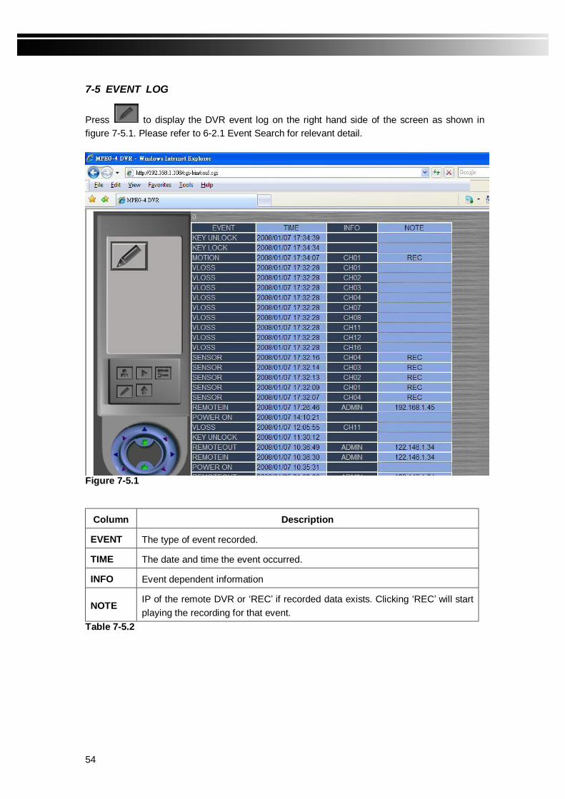
7-5 EVENT LOG
Press to display the DVR event log on the right hand side of the screen as shown in figure 7-5.1. Please refer to 6-2.1 Event Search for relevant detail.
Figure 7-5.1
Column Description
EVENT The type of event recorded.
TIME The date and time the event occurred.
INFO Event dependent information
NOTE IP of the remote DVR or ‘REC’ if recorded data exists. Clicking ‘REC’ will start playing the recording for that event.
Table 7-5.2

55
7-6 REMOTE PLAYBACK
Pressing the button will start remote playback as shown in Figure 7-6.1. Table 7-6.1 describes the operations of remote playback.
Figure 7-6.1

56
Table 7-6.1
Item Description
Select a channel to playback.
Switch to audio channel 1-4 or turn off audio.
Enable/Disable local storage of playback.
Start / Pause playback.
Fast rewind.
Fast forward.
Stop playback.
57
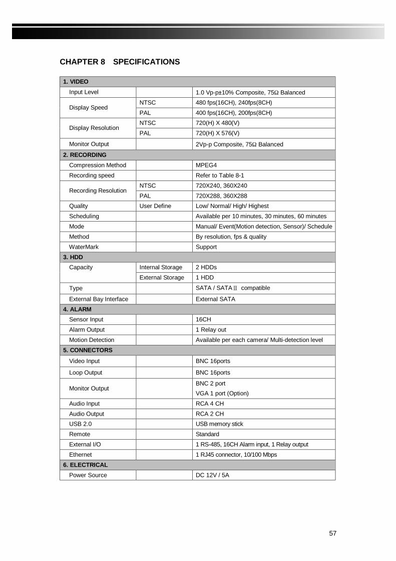
CHAPTER 8 SPECIFICATIONS 1. VIDEO
Input Level 1.0 Vp-p±10% Composite, 75Ω Balanced NTSC 480 fps(16CH), 240fps(8CH)
Display Speed PAL 400 fps(16CH), 200fps(8CH) NTSC 720(H) X 480(V)
Display Resolution PAL 720(H) X 576(V)
Monitor Output 2Vp-p Composite, 75Ω Balanced
2. RECORDING
Compression Method MPEG4
Recording speed Refer to Table 8-1
NTSC 720X240, 360X240 Recording Resolution
PAL 720X288, 360X288 Quality User Define Low/ Normal/ High/ Highest
Scheduling Available per 10 minutes, 30 minutes, 60 minutes
Mode Manual/ Event(Motion detection, Sensor)/ Schedule
Method By resolution, fps & quality
WaterMark Support
3. HDD Internal Storage 2 HDDs Capacity
External Storage 1 HDD
Type SATA / SATAⅡ compatible
External Bay Interface External SATA
4. ALARM Sensor Input 16CH
Alarm Output 1 Relay out
Motion Detection Available per each camera/ Multi-detection level
5. CONNECTORS
Video Input BNC 16ports
Loop Output BNC 16ports
Monitor Output BNC 2 port VGA 1 port (Option)
Audio Input RCA 4 CH
Audio Output RCA 2 CH USB 2.0 USB memory stick
Remote Standard
External I/O 1 RS-485, 16CH Alarm input, 1 Relay output
Ethernet 1 RJ45 connector, 10/100 Mbps
6. ELECTRICAL
Power Source DC 12V / 5A
58
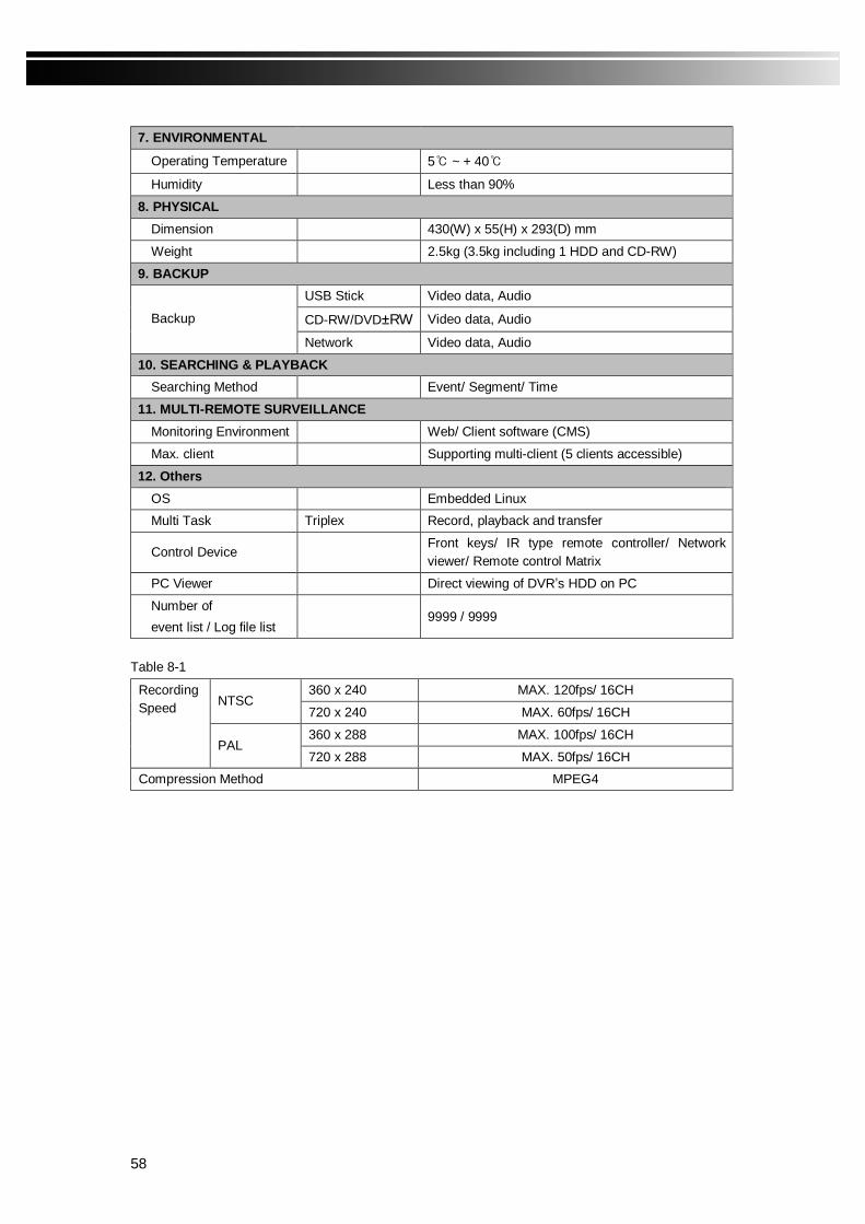
7. ENVIRONMENTAL
Operating Temperature 5 ~ + 40
Humidity Less than 90%
8. PHYSICAL Dimension 430(W) x 55(H) x 293(D) mm
Weight 2.5kg (3.5kg including 1 HDD and CD-RW)
9. BACKUP USB Stick Video data, Audio
CD-RW/DVD±RW Video data, Audio Backup
Network Video data, Audio
10. SEARCHING & PLAYBACK Searching Method Event/ Segment/ Time
11. MULTI-REMOTE SURVEILLANCE Monitoring Environment Web/ Client software (CMS)
Max. client Supporting multi-client (5 clients accessible)
12. Others
OS Embedded Linux Multi Task Triplex Record, playback and transfer
Control Device Front keys/ IR type remote controller/ Network viewer/ Remote control Matrix
PC Viewer Direct viewing of DVR’s HDD on PC
Number of event list / Log file list
9999 / 9999
Table 8-1
360 x 240 MAX. 120fps/ 16CH NTSC
720 x 240 MAX. 60fps/ 16CH
360 x 288 MAX. 100fps/ 16CH
Recording Speed
PAL 720 x 288 MAX. 50fps/ 16CH
Compression Method MPEG4
59
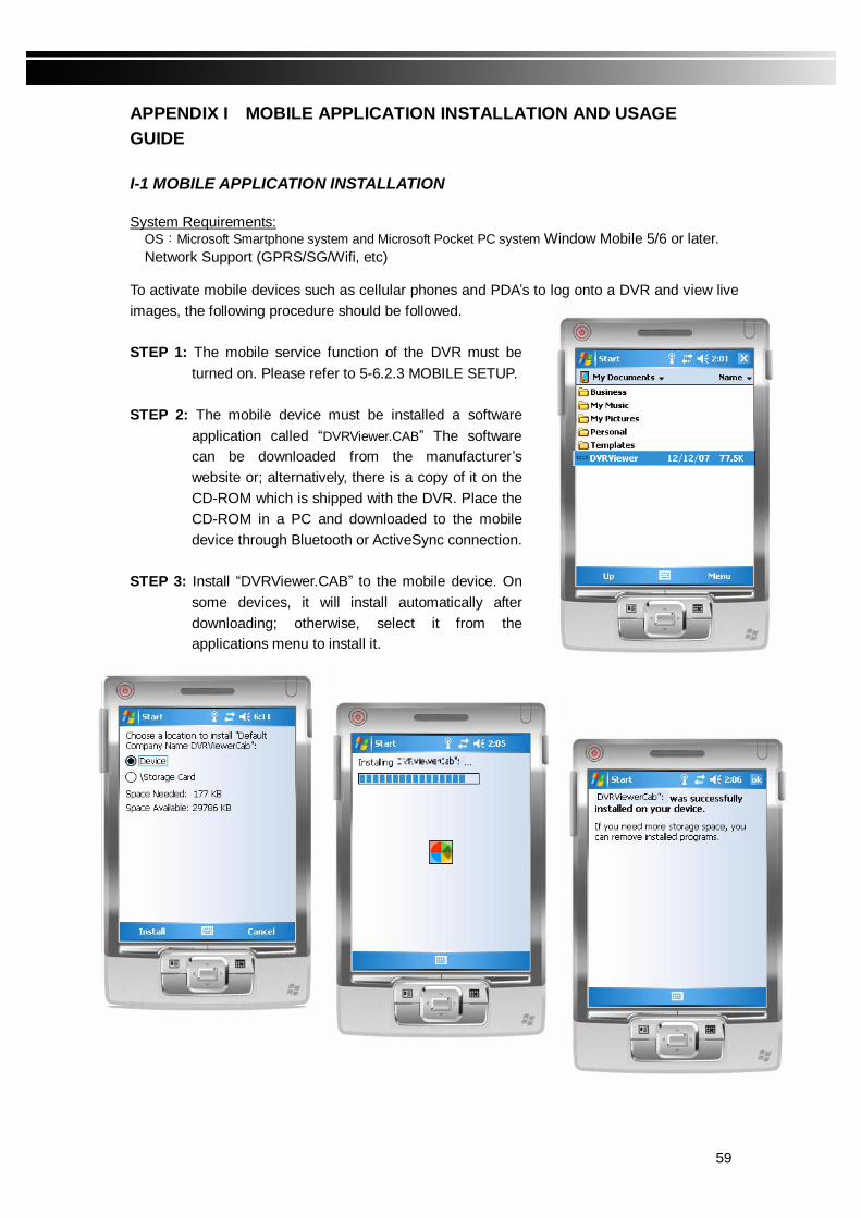
APPENDIX I MOBILE APPLICATION INSTALLATION AND USAGE GUIDE I-1 MOBILE APPLICATION INSTALLATION System Requirements:
OS:Microsoft Smartphone system and Microsoft Pocket PC system Window Mobile 5/6 or later. Network Support (GPRS/SG/Wifi, etc)
To activate mobile devices such as cellular phones and PDA’s to log onto a DVR and view live images, the following procedure should be followed. STEP 1: The mobile service function of the DVR must be
turned on. Please refer to 5-6.2.3 MOBILE SETUP. STEP 2: The mobile device must be installed a software
application called “DVRViewer.CAB” The software can be downloaded from the manufacturer’s website or; alternatively, there is a copy of it on the CD-ROM which is shipped with the DVR. Place the CD-ROM in a PC and downloaded to the mobile device through Bluetooth or ActiveSync connection.
STEP 3: Install “DVRViewer.CAB” to the mobile device. On
some devices, it will install automatically after downloading; otherwise, select it from the applications menu to install it.
60
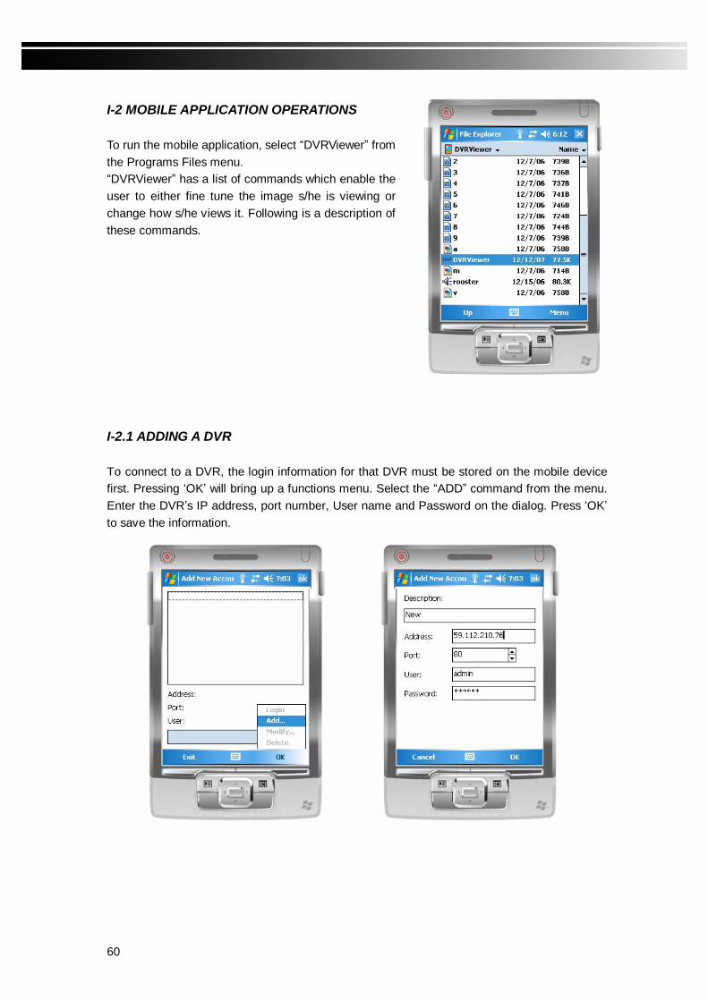
I-2 MOBILE APPLICATION OPERATIONS To run the mobile application, select “DVRViewer” from the Programs Files menu. “DVRViewer” has a list of commands which enable the user to either fine tune the image s/he is viewing or change how s/he views it. Following is a description of these commands. I-2.1 ADDING A DVR To connect to a DVR, the login information for that DVR must be stored on the mobile device first. Pressing ‘OK’ will bring up a functions menu. Select the “ADD” command from the menu. Enter the DVR’s IP address, port number, User name and Password on the dialog. Press ‘OK’ to save the information.
61
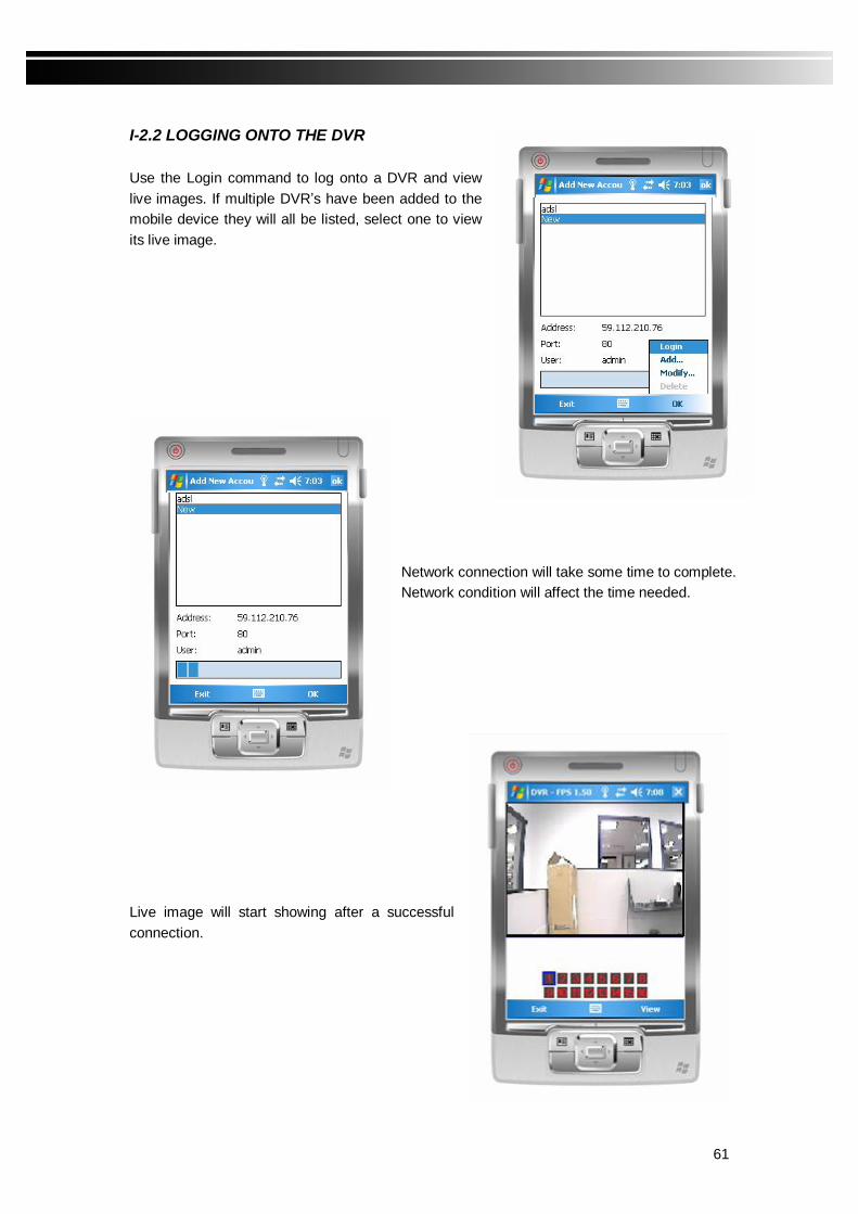
I-2.2 LOGGING ONTO THE DVR Use the Login command to log onto a DVR and view live images. If multiple DVR’s have been added to the mobile device they will all be listed, select one to view its live image.
Network connection will take some time to complete. Network condition will affect the time needed.
Live image will start showing after a successful connection.

62
I-2.3 MODIFYING A DVR’S LOGIN INFORMATION A DVR’s login information may change over time. Use the “MODIFY” command to change it. The dialogue is identical to that of the ADD command; simply enter the new login information.
I-2.4 DELETING A DVR When a DVR is no longer needed for viewing, use the “DELETE” command to remove it from the mobile device. Select a DVR from the list the select ‘Delete’.

63
I-3 LIVE VIEWING OPERATIONS After a successful connection, live images will start to flow through to the mobile device. Pressing ‘View’ will bring up a functions menu. Following is a description of the functions
I-3.1 SINGLE CHANNEL VIEWING Live images can be viewed one channel at a time.
64
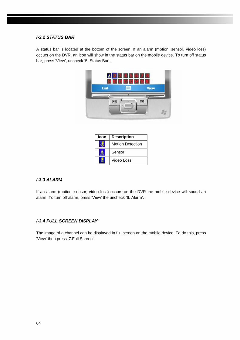
I-3.2 STATUS BAR A status bar is located at the bottom of the screen. If an alarm (motion, sensor, video loss) occurs on the DVR, an icon will show in the status bar on the mobile device. To turn off status bar, press ‘View’, uncheck ‘5. Status Bar’.
Icon Description
Motion Detection
Sensor
Video Loss
I-3.3 ALARM
If an alarm (motion, sensor, video loss) occurs on the DVR the mobile device will sound an alarm. To turn off alarm, press ‘View’ the uncheck ‘6. Alarm’.
I-3.4 FULL SCREEN DISPLAY
The image of a channel can be displayed in full screen on the mobile device. To do this, press ‘View’ then press ‘7.Full Screen’.

65
APPENDIX II CMS INSTALLATION AND USAGE GUIDE
Ⅱ-1 CMS INSTALLATION System Requirements Intel Pentium 4 processor or equivalent. Microsoft Windows Vista、Windows XP、Windows 2003 Server. 512MB memory. 20MB hard disk space. Recording and image capturing require more space. Installation: 1. Connect to the manufacturer’s website and download the CMS software. 2. Decompress and execute setup.exe. 3. Select ‘Next’
4. Select ‘Browse’ to change installation path if so desire. To find out available space on the
local hard disk, select ‘Disk Cost’. Select ‘Next’.

66
5. ‘Confirm Installation’ shows. Select ‘Next’ and the installation starts.
6. When ‘Installation Complete’ shows select ‘Close’ to finish installation.

67
Ⅱ-2 CMS LOGIN AND ENVIRONMENT To enter CMS, the administrator’s user name and password must be entered. The default is ‘admin’ and ‘123456’.
After successful login, the following screen shows.
① DVRs, Groups & Events Information about DVRs, groups and events. See II-3 for detail.
② Local information display and control
Information about local hard disk, volume, recording, etc. See II-4 for more detail.
③ Main Display Live image display area. See II-5 for detail.
④ Display Modes Display modes supported by CMS.
⑤ Functions Bar A set of 10 functions are provided by CMS. See II-6 for detail.
③ ①
② ④ ⑤

68
Ⅱ-3 DVRs, Groups and Events
Icon Description
View DVR/Group list.
View event logs.
Ⅱ-3.1 View DVR/Group List Single left click on ‘DVR’ or ‘Group’ will expand/collapse all the DVRs and groups. On the DVR list, double left click on a connected DVR will show live image from the DVR in the main display. See II-6.2 for DVR Administration. On the Group list, double left click on a group will show live image from the channels of the group in the main display. See II-6.3 for Group Administration. On the DVR list, single left click on a connected DVR will expand/collapse status of the 16 channels.
Icon Description
Video Loss
Motion detected
Sensor triggered

69
Ⅱ-3.2 View Event Logs
In this display, all the events of a DVR can be expanded/collapsed in the order of Remote in/Remote out, Video Loss, Motion, Sensor, Others (Power Reset, Key lock, Key unlock, HD Full).
Ⅱ-4 Local Information Display and Control This area is located at the lower left of the main display.
Icon Function Description
HDD info
Shows the ratio of available space / HDD size of the C:\ drive.
Volume PC volume or playback volume control bar.
Recording
Record live image on local storage. To view locally stored images, use Record function. See II-6.10 for detail.
Snapshot
Record the live still image on the display on local storage. Use Snapshot function to view locally recorded still images. See II-6.9 for detail.

70
Ⅱ-5 Main Display The main display area is where the live image of the DVR is shown. Each channel can change position in the display, switch audio source, retrieve eMap, and control PTZ, etc.
Ⅱ-5.1 Audio Control In live mode, there are four audio channels to select from. Only one audio channel can be turned on at any time.
「 」audio channel is on.
「 」audio channel is off. Clicking the icon will turn on/off audio.

71
Ⅱ-5.2 eMap Display
In live mode, pressing will show the e-Map drag-down menu. If the channel is set up to use e-Map, the menu will show all the e-Maps titles that have been added to this channel; otherwise, ‘No eMaps’ will show. For details about e-Map setup, please refer to II-6.4 eMap Administration.
Ⅱ-5.3 PTZ Control In the main display, right click the mouse will show PTZ control as shown below.
Icon Description 8 Direction Keys Rotate the PTZ
ZOOM+:Zoom in on the picture.
ZOOM-:Zoom out of the picture.
Ⅱ-6 Functions Bar CMS provides ten functions to empower multiple DVRs management and viewing.

72
TableⅡ-6-1 Ten functions icons and description.
Icon Description
User Administration.
DVR Administration.
Group Administration.
eMap Administration.
Remote Playback.
HDD Playback.
File Playback.
Event Playback.
Snapshot.
Recording.
Ⅱ-6.1 User Administration Before the CMS can be used on a PC, user accounts should be added with proper privilege. Each user should also be assigned a password and optionally a description. If a user does not have certain privilege assigned he/she will not be able to use the corresponding function on the Functions Bar. The default is none of the privilege is assigned. The administrator should assign proper privilege to each user. These user accounts can be deleted or edited in the future. Press OK to save the settings. Icon Description
Add a user account.
Delete a user account.
73
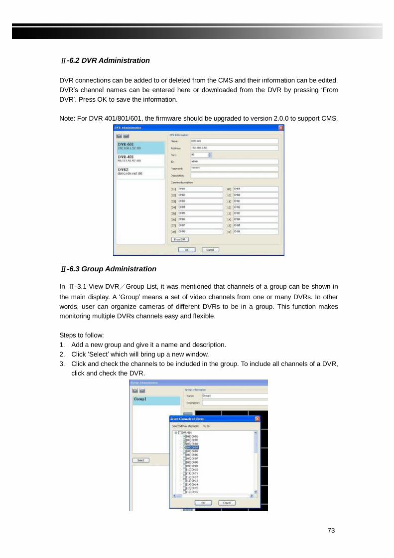
Ⅱ-6.2 DVR Administration DVR connections can be added to or deleted from the CMS and their information can be edited. DVR’s channel names can be entered here or downloaded from the DVR by pressing ‘From DVR’. Press OK to save the information. Note: For DVR 401/801/601, the firmware should be upgraded to version 2.0.0 to support CMS.
Ⅱ-6.3 Group Administration In Ⅱ-3.1 View DVR/Group List, it was mentioned that channels of a group can be shown in the main display. A ‘Group’ means a set of video channels from one or many DVRs. In other words, user can organize cameras of different DVRs to be in a group. This function makes monitoring multiple DVRs channels easy and flexible. Steps to follow: 1. Add a new group and give it a name and description. 2. Click ‘Select’ which will bring up a new window. 3. Click and check the channels to be included in the group. To include all channels of a DVR,
click and check the DVR.
74
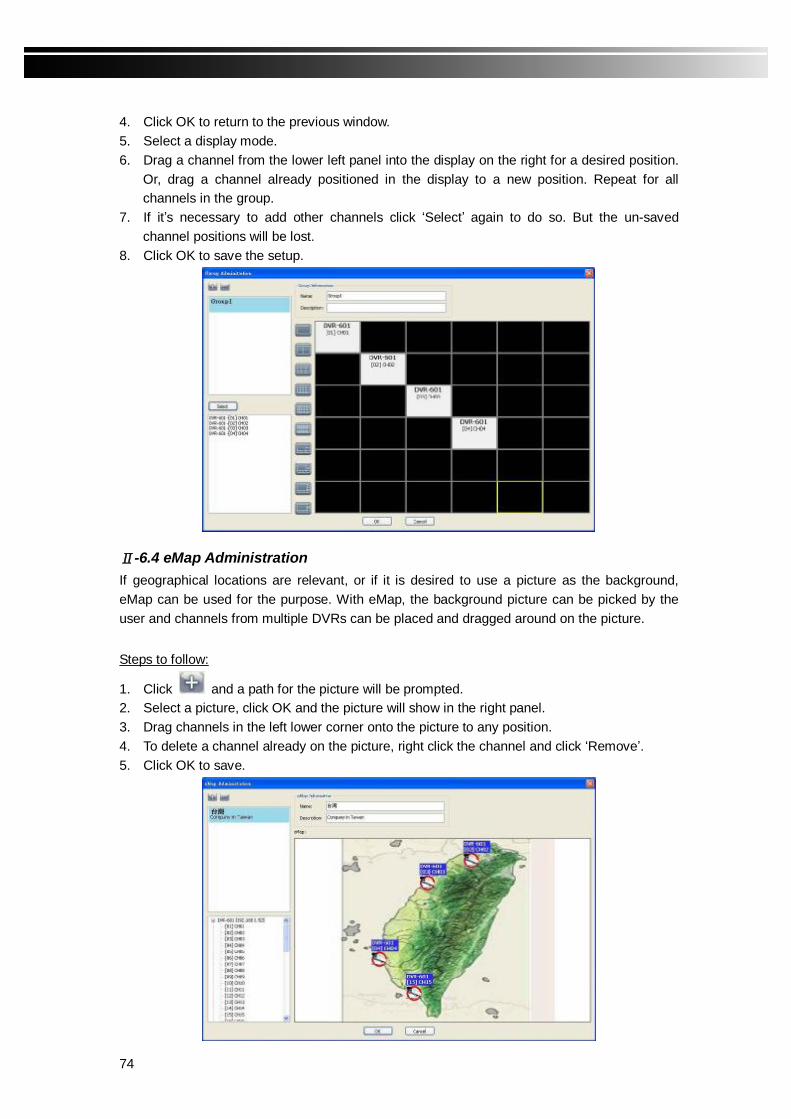
4. Click OK to return to the previous window. 5. Select a display mode. 6. Drag a channel from the lower left panel into the display on the right for a desired position.
Or, drag a channel already positioned in the display to a new position. Repeat for all channels in the group.
7. If it’s necessary to add other channels click ‘Select’ again to do so. But the un-saved channel positions will be lost.
8. Click OK to save the setup.
Ⅱ-6.4 eMap Administration If geographical locations are relevant, or if it is desired to use a picture as the background, eMap can be used for the purpose. With eMap, the background picture can be picked by the user and channels from multiple DVRs can be placed and dragged around on the picture.
Steps to follow:
1. Click and a path for the picture will be prompted. 2. Select a picture, click OK and the picture will show in the right panel. 3. Drag channels in the left lower corner onto the picture to any position. 4. To delete a channel already on the picture, right click the channel and click ‘Remove’. 5. Click OK to save.

75
Ⅱ-6.5 Remote Play Video images recorded on a DVR can be displayed on a remote CMS. With Remote Play function, select a DVR and a display mode on top of the screen. After the recorded segments are listed below, double click on one to show its image on the right.
Icon Description
Start playing.
Pause.
Fast forward.
Fast rewind.

76
Ⅱ-6.6 HDD Play A DVR’s Hard disk can be detached and re-attached to a PC and the CMS software can be used to retrieve and play recorded images on the PC. As shown below, recording segments are listed on the left; the display with desired display mode is on the right. Select a recording segment and click ‘PLAY’ icon will show it in the display. The playback can be controlled with a control bar at the bottom.
Ⅱ-6.7 File Play With CMS, PES files on the PC can be played back. Usage and adjustments of the display are similar to those aforementioned for other functions.
Icon Description
Start Playback.
Pause.
Stop playback.
Fast forward.
Fast rewind.

77
Ⅱ-6.8 Event Play Event recordings on the DVR can be played back in CMS. Steps to follow: 1. Select a DVR and a display mode. 2. Select a date. 3. Double click an event and play back the images on the right. Use buttons at the bottom to control the playback.
78
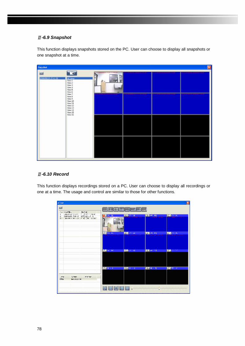
Ⅱ-6.9 Snapshot This function displays snapshots stored on the PC. User can choose to display all snapshots or one snapshot at a time.
Ⅱ-6.10 Record This function displays recordings stored on a PC. User can choose to display all recordings or one at a time. The usage and control are similar to those for other functions.
79
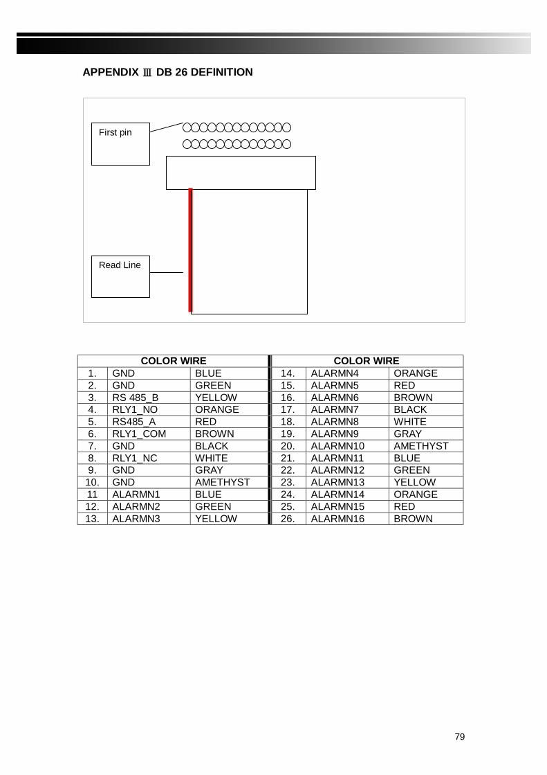
APPENDIX Ⅲ DB 26 DEFINITION
COLOR WIRE COLOR WIRE 1. GND BLUE 14. ALARMN4 ORANGE 2. GND GREEN 15. ALARMN5 RED 3. RS 485_B YELLOW 16. ALARMN6 BROWN 4. RLY1_NO ORANGE 17. ALARMN7 BLACK 5. RS485_A RED 18. ALARMN8 WHITE 6. RLY1_COM BROWN 19. ALARMN9 GRAY 7. GND BLACK 20. ALARMN10 AMETHYST 8. RLY1_NC WHITE 21. ALARMN11 BLUE 9. GND GRAY 22. ALARMN12 GREEN
10. GND AMETHYST 23. ALARMN13 YELLOW 11 ALARMN1 BLUE 24. ALARMN14 ORANGE 12. ALARMN2 GREEN 25. ALARMN15 RED 13. ALARMN3 YELLOW 26. ALARMN16 BROWN
Read Line
First pin