,96#:5+@=2c 92c86 @?ec@==6c !?decf4e:@?%2?f2= · pdf filet/:@> 1$5#,96#:5+@=2c 92c86...
TRANSCRIPT
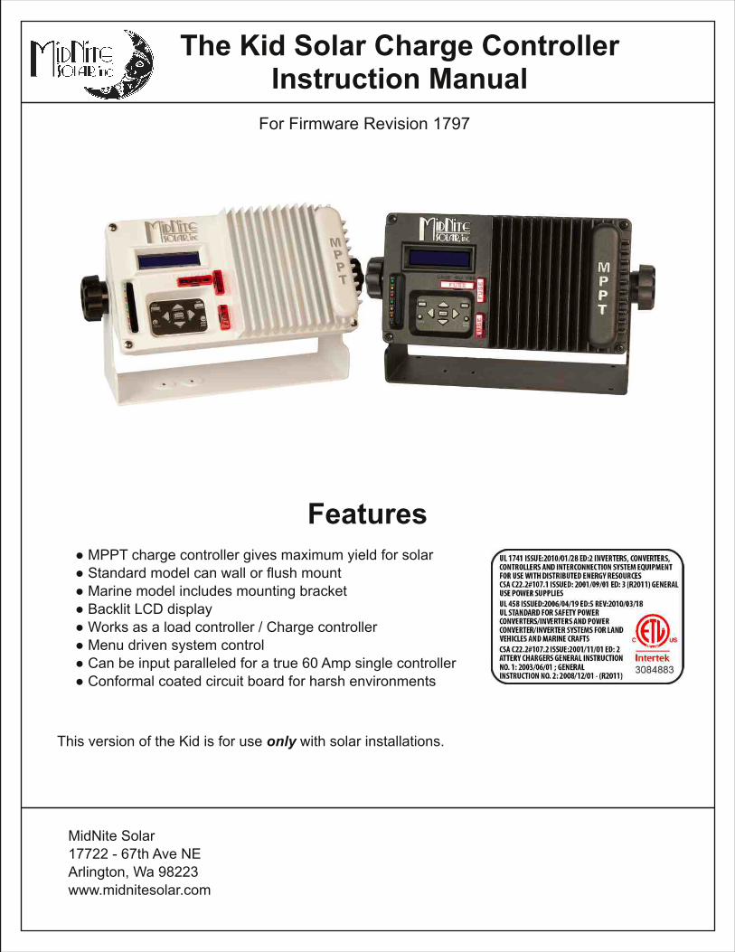
The Kid Solar Charge ControllerInstruction Manual
MidNite Solar1 7722 - 67th Ave NEArlington, Wa 98223www.midnitesolar.com
Features● MPPT charge control ler gives maximum yield for solar● Standard model can wall or flush mount● Marine model includes mounting bracket● Backlit LCD display● Works as a load control ler / Charge control ler● Menu driven system control● Can be input paral leled for a true 60 Amp single control ler● Conformal coated circuit board for harsh environments
This version of the Kid is for use onlywith solar instal lations.
For Firmware Revision 1 797

2 | Page 1 0-268-1 REV D
The Kid Solar Charge Controller Instructions
IMPORTANT SAFETY INSTRUCTIONSSAVE THESE INSTRUCTIONS - THESE INSTRUCTIONS CONTAIN IMPORTANT SAFETY AND OPERATING INSTRUCTIONS FORTHE KID CHARGE CONTROLLER MODEL NUMBERS MNKID-B, MNKID-W, MNKID-M-B, MNKID-M-W.
I f you do not ful ly understand any of the concepts, terminology, or hazards outl ined in these instructions, please refer instal lation to a qualified dealer, electrician orinstal ler. These instructions are not meant to be a complete explanation of a renewable energy system. All instal lations must comply with national and local electricalcodes. Professional instal lation is recommended.
GENERAL PRECAUTIONS:WORKING WITH OR IN THE VICINITY OF A LEAD ACID BATTERY, SEALED OR VENTED IS DANGEROUS. VENTEDBATTERIES GENERATE EXPLOSIVE GASES DURING NORMAL OPERATION. FOR THIS REASON, IT IS VERYIMPORTANT THAT BEFORE SERVICING EQUIPMENT IN THE VICINITY OF LEAD-ACID BATTERIES YOU REVIEW ANDFOLLOW THESE INSTRUCTIONS CAREFULLY.
I f service or repair should become necessary, contact MidNite Solar Inc. Improper servicing may result in a risk of shock, fire or explosion. To reducethese risks, disconnect al l wiring before attempting any maintenance or cleaning. Turning off the inverter wil l not reduce these risks. Solar modulesproduce power when exposed to l ight. When it is not possible to disconnect the power coming from the Photovoltaics by an external means such as acombiner, cover the modules with an opaque material before servicing any connected equipment.
Do Not expose to rain or snow. NEVER attempt to charge a frozen battery. Do not smoke around batteries.
When it is necessary to remove a battery, make sure that the battery bank disconnect breaker is in the off position and that the PV breakers, gridbreakers and any other sources of power to the inverter are in the off position. Then remove the negative terminal from the battery first.
To reduce risk of battery explosion fol low these instructions and those published by the battery manufacturer as well as the manufacturer of anyadditional equipment used in the vicinity of the batteries.Avoid producing sparks in the vicinity of the batteries when using vented batteries. Provide venti lation to clear the area of explosive gases. Sealed AGMand Gel batteries do not under normal conditions create explosive gases. Refer to the battery manufacturer's documentation. Be especial ly cautiouswhen using metal tools. Dropping a metal tool onto batteries can short circuit them. The resulting spark can lead to personal injury or damage to theequipment. Provide venti lation to outdoors from the battery compartment when instal l ing vented batteries such as golf cart T-1 05 batteries. The additionof a spil l tray is also a good idea.
Clean all battery terminals. Very high currents are drawn from the batteries; even a small amount of electrical resistance can result in overheating, poorperformance, premature fai lure or even fire.Have plenty of fresh water and soap nearby in case battery acid contacts skin, clothing or eyes. Wear complete eye and clothing protection. Alwaysavoid touching eyes while working near batteries. I f battery acid or battery terminal corrosion contacts skin or clothing, wash immediately with soap andwater. I f acid enters the eyes, immediately flood with cool running water for at least 1 5 minutes and get medical attention immediately. Baking sodaneutral izes battery acid electrolyte. Keep a supply near the batteries
Do not work alone. Someone should be in the range of your voice or close enough to come to your aid when you work with or near electrical equipment.Remove rings, bracelets, necklaces, watches etc. when working with batteries, photovoltaic modules or other electrical equipment. Power from anil luminated photovoltaic array makes a very effective arc welder with dire consequences if one of the welded pieces is on your person.
To reduce the risk of injury, connect only deep cycle lead acid type rechargeable batteries. Other types of batteries may leak or burst, causing personalinjury or damage.
Wiring methods used shall be in accordance with the Canadian Electrical Code, Part I .Wiring must be done in accordance with the National Electrical Code Article 690 ANSI/NFPA 70. Use Class 1 wiring methods for field wiring connectionsto terminals of a Class 2 circuit. Use only 1 4-1 0 gauge AWM wire. Select the wire gauge used based on the protection provided by the circuitbreakers/fuses. Overcurrent protection must be instal led as part of the system instal lation. Refer to the wiring diagrams provided inthis manual for breaker/fuse/GFDI sizes and model numbers.
WARNING: This unit is not provided with a GFDI device. This inverter or charge control ler must be used with an external GFDI device as required bythe Article 690 of the National Electrical Code for the instal lation location.
Use of attachments or accessories not approved by MidNite Solar could result in damage or injury.Before making any connections verify that the circuit breakers are in the off position including the inverter breaker. Double check all wiring beforeapplying power.
The Kid Solar Charge Controller Instructions
3 | Page 1 0-268-1 REV D
INSTRUCTIONS DE SÉCURITÉ IMPORTANTESCONSERVER CES INSTRUCTIONS - CES INSTRUCTIONS CONTIENNENT DES INFORMATIONSIMPORTANTES POUR UTILISER LE MIDNITE SOLAR THE KID CHARGE CONTROLLER(RÉGULATEUR DE CHARGE) MODEL NUMBERS MNKID-B, MNKID-W, MNKID-M-B, MNKID-M-WEN TOUTE SÉCURITÉ.
Avant l ’uti l isez cet appareil l is et comprends toutes les instructions et avertissements.
Si vous ne comprenez pas l’une des concepts ou des instructions contenu dans cette manuel consulterun agent spécial isé.
Si des réparations sont nécessaires contactez MidNite Solar pour plus des informations. Danger dechoc électrique et de risque de brulure. Rien à dépanner à l 'intérieure du cette appareil . Ne pas ouvrir lecouver. Pour toute réparation ou service d'entretien, consulter un agent spécial isé. I l y’a peut-êtreplusieurs sources d’al imentation dans cette system. Débrancher toutes les interrupteurs avant touted'entretien où nettoyage.
Ne travail lez pas seul. Quelqu'un devrait toujours être à proximité pour aider en cas d'une situationd'urgence.
Retirer bagues, bracelets, col l iers, montres, et quelles choses comme ça. I l y’a risque des blessuresgraves s’i l y’a un court-circuit. Cela pourrait ruiner votre journée entière.
Cette appareil n'avoir pas un détecteur des fautes de terre. C'est nécessaire de emploi la protectioncontre des fautes de terre a l 'extérieure de cette appareil en conformité avec le National ElectricalCode.
Les méthodes de câblage uti l isés doivent être conformes au Code canadien de l 'électricité, Partie I .
Le câblage doit être fait en conformité avec le National Electrical Code Article 690 ANSI / NFPA 70.Uti l iser des méthodes de câblage de catégorie 1 pour les connexions de câblage sur .des terminauxd'un circuit de classe 2. Uti l isez uniquement des fi ls de AWM de calibre 1 4-1 /0. Sélectionnez le type decâble uti l isé sur la base de la protection prévue par les disjoncteurs / fusibles.

4 | Page 1 0-268-1 REV D
The Kid Solar Charge Controller Instructions
IMPORTANT SAFETY INSTRUCTIONSSAVE THESE INSTRUCTIONS - THESE INSTRUCTIONS CONTAIN IMPORTANT SAFETY AND OPERATING INSTRUCTIONS FORTHE KID CHARGE CONTROLLER MODEL NUMBERS MNKID-B, MNKID-W, MNKID-M-B, MNKID-M-W.
I f you do not ful ly understand any of the concepts, terminology, or hazards outl ined in these instructions, please refer instal lation to a qualified dealer, electrician orinstal ler. These instructions are not meant to be a complete explanation of a renewable energy system. All instal lations must comply with national and local electricalcodes. Professional instal lation is recommended.
GENERAL PRECAUTIONS:WORKING WITH OR IN THE VICINITY OF A LEAD ACID BATTERY, SEALED OR VENTED IS DANGEROUS. VENTEDBATTERIES GENERATE EXPLOSIVE GASES DURING NORMAL OPERATION. FOR THIS REASON, IT IS VERYIMPORTANT THAT BEFORE SERVICING EQUIPMENT IN THE VICINITY OF LEAD-ACID BATTERIES YOU REVIEW ANDFOLLOW THESE INSTRUCTIONS CAREFULLY.
I f service or repair should become necessary, contact MidNite Solar Inc. Improper servicing may result in a risk of shock, fire or explosion. To reducethese risks, disconnect al l wiring before attempting any maintenance or cleaning. Turning off the inverter wil l not reduce these risks. Solar modulesproduce power when exposed to l ight. When it is not possible to disconnect the power coming from the Photovoltaics by an external means such as acombiner, cover the modules with an opaque material before servicing any connected equipment.
Do Not expose to rain or snow. NEVER attempt to charge a frozen battery. Do not smoke around batteries.
When it is necessary to remove a battery, make sure that the battery bank disconnect breaker is in the off position and that the PV breakers, gridbreakers and any other sources of power to the inverter are in the off position. Then remove the negative terminal from the battery first.
To reduce risk of battery explosion fol low these instructions and those published by the battery manufacturer as well as the manufacturer of anyadditional equipment used in the vicinity of the batteries.Avoid producing sparks in the vicinity of the batteries when using vented batteries. Provide venti lation to clear the area of explosive gases. Sealed AGMand Gel batteries do not under normal conditions create explosive gases. Refer to the battery manufacturer's documentation. Be especial ly cautiouswhen using metal tools. Dropping a metal tool onto batteries can short circuit them. The resulting spark can lead to personal injury or damage to theequipment. Provide venti lation to outdoors from the battery compartment when instal l ing vented batteries such as golf cart T-1 05 batteries. The additionof a spil l tray is also a good idea.
Clean all battery terminals. Very high currents are drawn from the batteries; even a small amount of electrical resistance can result in overheating, poorperformance, premature fai lure or even fire.Have plenty of fresh water and soap nearby in case battery acid contacts skin, clothing or eyes. Wear complete eye and clothing protection. Alwaysavoid touching eyes while working near batteries. I f battery acid or battery terminal corrosion contacts skin or clothing, wash immediately with soap andwater. I f acid enters the eyes, immediately flood with cool running water for at least 1 5 minutes and get medical attention immediately. Baking sodaneutral izes battery acid electrolyte. Keep a supply near the batteries
Do not work alone. Someone should be in the range of your voice or close enough to come to your aid when you work with or near electrical equipment.Remove rings, bracelets, necklaces, watches etc. when working with batteries, photovoltaic modules or other electrical equipment. Power from anil luminated photovoltaic array makes a very effective arc welder with dire consequences if one of the welded pieces is on your person.
To reduce the risk of injury, connect only deep cycle lead acid type rechargeable batteries. Other types of batteries may leak or burst, causing personalinjury or damage.
Wiring methods used shall be in accordance with the Canadian Electrical Code, Part I .Wiring must be done in accordance with the National Electrical Code Article 690 ANSI/NFPA 70. Use Class 1 wiring methods for field wiring connectionsto terminals of a Class 2 circuit. Use only 1 4-1 0 gauge AWM wire. Select the wire gauge used based on the protection provided by the circuitbreakers/fuses. Overcurrent protection must be instal led as part of the system instal lation. Refer to the wiring diagrams provided inthis manual for breaker/fuse/GFDI sizes and model numbers.
WARNING: This unit is not provided with a GFDI device. This inverter or charge control ler must be used with an external GFDI device as required bythe Article 690 of the National Electrical Code for the instal lation location.
Use of attachments or accessories not approved by MidNite Solar could result in damage or injury.Before making any connections verify that the circuit breakers are in the off position including the inverter breaker. Double check all wiring beforeapplying power.
Warnings. . . . . . . . . . . . . . . . . . . . . . . . . . . . . . . . . . . . . . . . . . . . . . . . . . . . . . . . . . . . . . . . . . . . . . . . . . . . . . . . . . . . . . . . . . . . . . 2The Kid Dimensions. . . . . . . . . . . . . . . . . . . . . . . . . . . . . . . . . . . . . . . . . . . . . . . . . . . . . . . . . . . . . . . . . . . . . . . . . . . . . 6Mounting The Kid. . . . . . . . . . . . . . . . . . . . . . . . . . . . . . . . . . . . . . . . . . . . . . . . . . . . . . . . . . . . . . . . . . . . . . . . . . . . . . . . . 6Stickers. . . . . . . . . . . . . . . . . . . . . . . . . . . . . . . . . . . . . . . . . . . . . . . . . . . . . . . . . . . . . . . . . . . . . . . . . . . . . . . . . . . . . . . . . . . . . . . . 8Wiring. . . . . . . . . . . . . . . . . . . . . . . . . . . . . . . . . . . . . . . . . . . . . . . . . . . . . . . . . . . . . . . . . . . . . . . . . . . . . . . . . . . . . . . . . . . . . . . . . . . 1 3Aux Input / Output. . . . . . . . . . . . . . . . . . . . . . . . . . . . . . . . . . . . . . . . . . . . . . . . . . . . . . . . . . . . . . . . . . . . . . . . . . . . . . . . 1 6MNBTS Battery Temperature Sensor. . . . . . . . . . . . . . . . . . . . . . . . . . . . . . . . . . . . . . . . . . . . . . . . . . . 1 8Stacking The Kid. . . . . . . . . . . . . . . . . . . . . . . . . . . . . . . . . . . . . . . . . . . . . . . . . . . . . . . . . . . . . . . . . . . . . . . . . . . . . . . . . . 1 8Set-Up and Use. . . . . . . . . . . . . . . . . . . . . . . . . . . . . . . . . . . . . . . . . . . . . . . . . . . . . . . . . . . . . . . . . . . . . . . . . . . . . . . . . . . 20Status Screens. . . . . . . . . . . . . . . . . . . . . . . . . . . . . . . . . . . . . . . . . . . . . . . . . . . . . . . . . . . . . . . . . . . . . . . . . . . . . . . . . . . . . 24The Kid Keypad. . . . . . . . . . . . . . . . . . . . . . . . . . . . . . . . . . . . . . . . . . . . . . . . . . . . . . . . . . . . . . . . . . . . . . . . . . . . . . . . . . . 25Firmware Update. . . . . . . . . . . . . . . . . . . . . . . . . . . . . . . . . . . . . . . . . . . . . . . . . . . . . . . . . . . . . . . . . . . . . . . . . . . . . . . . . 38Automatic Generator Starting - AGS.. . . . . . . . . . . . . . . . . . . . . . . . . . . . . . . . . . . . . . . . . . . . . . . . . . . 40Wiring Diagrams. . . . . . . . . . . . . . . . . . . . . . . . . . . . . . . . . . . . . . . . . . . . . . . . . . . . . . . . . . . . . . . . . . . . . . . . . . . . . . . . . . 44HyperVOC.. . . . . . . . . . . . . . . . . . . . . . . . . . . . . . . . . . . . . . . . . . . . . . . . . . . . . . . . . . . . . . . . . . . . . . . . . . . . . . . . . . . . . . . . . . . 48Power Graph. . . . . . . . . . . . . . . . . . . . . . . . . . . . . . . . . . . . . . . . . . . . . . . . . . . . . . . . . . . . . . . . . . . . . . . . . . . . . . . . . . . . . . . . 49Accessories. . . . . . . . . . . . . . . . . . . . . . . . . . . . . . . . . . . . . . . . . . . . . . . . . . . . . . . . . . . . . . . . . . . . . . . . . . . . . . . . . . . . . . . . . . 49Whiz Bang Jr. Current Monitoring. . . . . . . . . . . . . . . . . . . . . . . . . . . . . . . . . . . . . . . . . . . . . . . . . . . . . . . . 52Warranty Information. . . . . . . . . . . . . . . . . . . . . . . . . . . . . . . . . . . . . . . . . . . . . . . . . . . . . . . . . . . . . . . . . . . . . . . . . . . . 54Specifications. . . . . . . . . . . . . . . . . . . . . . . . . . . . . . . . . . . . . . . . . . . . . . . . . . . . . . . . . . . . . . . . . . . . . . . . . . . . . . . . . . . . . . . 55Ratings / Fuses. . . . . . . . . . . . . . . . . . . . . . . . . . . . . . . . . . . . . . . . . . . . . . . . . . . . . . . . . . . . . . . . . . . . . . . . . . . . . . . . . . . . 56The Kid Menu Map. . . . . . . . . . . . . . . . . . . . . . . . . . . . . . . . . . . . . . . . . . . . . . . . . . . . . . . . . . . . . . . . . . . . . . . . . . . . . . . 57Glossary. . . . . . . . . . . . . . . . . . . . . . . . . . . . . . . . . . . . . . . . . . . . . . . . . . . . . . . . . . . . . . . . . . . . . . . . . . . . . . . . . . . . . . . . . . . . . . . 59Wall Mount Template. . . . . . . . . . . . . . . . . . . . . . . . . . . . . . . . . . . . . . . . . . . . . . . . . . . . . . . . . . . . . . . . . . . . . . . . . . . . 60
Table of Contents
Symbols used in this manual
Ground SymbolIndicates an earth ground connection.

The Kid Solar Charge Controller Instructions
5 | Page 1 0-268-1 REV D
Warnings. . . . . . . . . . . . . . . . . . . . . . . . . . . . . . . . . . . . . . . . . . . . . . . . . . . . . . . . . . . . . . . . . . . . . . . . . . . . . . . . . . . . . . . . . . . . . . 2The Kid Dimensions. . . . . . . . . . . . . . . . . . . . . . . . . . . . . . . . . . . . . . . . . . . . . . . . . . . . . . . . . . . . . . . . . . . . . . . . . . . . . 6Mounting The Kid. . . . . . . . . . . . . . . . . . . . . . . . . . . . . . . . . . . . . . . . . . . . . . . . . . . . . . . . . . . . . . . . . . . . . . . . . . . . . . . . . 6Stickers. . . . . . . . . . . . . . . . . . . . . . . . . . . . . . . . . . . . . . . . . . . . . . . . . . . . . . . . . . . . . . . . . . . . . . . . . . . . . . . . . . . . . . . . . . . . . . . . 8Wiring. . . . . . . . . . . . . . . . . . . . . . . . . . . . . . . . . . . . . . . . . . . . . . . . . . . . . . . . . . . . . . . . . . . . . . . . . . . . . . . . . . . . . . . . . . . . . . . . . . . 1 3Aux Input / Output. . . . . . . . . . . . . . . . . . . . . . . . . . . . . . . . . . . . . . . . . . . . . . . . . . . . . . . . . . . . . . . . . . . . . . . . . . . . . . . . 1 6MNBTS Battery Temperature Sensor. . . . . . . . . . . . . . . . . . . . . . . . . . . . . . . . . . . . . . . . . . . . . . . . . . . 1 8Stacking The Kid. . . . . . . . . . . . . . . . . . . . . . . . . . . . . . . . . . . . . . . . . . . . . . . . . . . . . . . . . . . . . . . . . . . . . . . . . . . . . . . . . . 1 8Set-Up and Use. . . . . . . . . . . . . . . . . . . . . . . . . . . . . . . . . . . . . . . . . . . . . . . . . . . . . . . . . . . . . . . . . . . . . . . . . . . . . . . . . . . 20Status Screens. . . . . . . . . . . . . . . . . . . . . . . . . . . . . . . . . . . . . . . . . . . . . . . . . . . . . . . . . . . . . . . . . . . . . . . . . . . . . . . . . . . . . 24The Kid Keypad. . . . . . . . . . . . . . . . . . . . . . . . . . . . . . . . . . . . . . . . . . . . . . . . . . . . . . . . . . . . . . . . . . . . . . . . . . . . . . . . . . . 25Firmware Update. . . . . . . . . . . . . . . . . . . . . . . . . . . . . . . . . . . . . . . . . . . . . . . . . . . . . . . . . . . . . . . . . . . . . . . . . . . . . . . . . 38Automatic Generator Starting - AGS.. . . . . . . . . . . . . . . . . . . . . . . . . . . . . . . . . . . . . . . . . . . . . . . . . . . 40Wiring Diagrams. . . . . . . . . . . . . . . . . . . . . . . . . . . . . . . . . . . . . . . . . . . . . . . . . . . . . . . . . . . . . . . . . . . . . . . . . . . . . . . . . . 44HyperVOC.. . . . . . . . . . . . . . . . . . . . . . . . . . . . . . . . . . . . . . . . . . . . . . . . . . . . . . . . . . . . . . . . . . . . . . . . . . . . . . . . . . . . . . . . . . . 48Power Graph. . . . . . . . . . . . . . . . . . . . . . . . . . . . . . . . . . . . . . . . . . . . . . . . . . . . . . . . . . . . . . . . . . . . . . . . . . . . . . . . . . . . . . . . 49Accessories. . . . . . . . . . . . . . . . . . . . . . . . . . . . . . . . . . . . . . . . . . . . . . . . . . . . . . . . . . . . . . . . . . . . . . . . . . . . . . . . . . . . . . . . . . 49Whiz Bang Jr. Current Monitoring. . . . . . . . . . . . . . . . . . . . . . . . . . . . . . . . . . . . . . . . . . . . . . . . . . . . . . . . 52Warranty Information. . . . . . . . . . . . . . . . . . . . . . . . . . . . . . . . . . . . . . . . . . . . . . . . . . . . . . . . . . . . . . . . . . . . . . . . . . . . 54Specifications. . . . . . . . . . . . . . . . . . . . . . . . . . . . . . . . . . . . . . . . . . . . . . . . . . . . . . . . . . . . . . . . . . . . . . . . . . . . . . . . . . . . . . . 55Ratings / Fuses. . . . . . . . . . . . . . . . . . . . . . . . . . . . . . . . . . . . . . . . . . . . . . . . . . . . . . . . . . . . . . . . . . . . . . . . . . . . . . . . . . . . 56The Kid Menu Map. . . . . . . . . . . . . . . . . . . . . . . . . . . . . . . . . . . . . . . . . . . . . . . . . . . . . . . . . . . . . . . . . . . . . . . . . . . . . . . 57Glossary. . . . . . . . . . . . . . . . . . . . . . . . . . . . . . . . . . . . . . . . . . . . . . . . . . . . . . . . . . . . . . . . . . . . . . . . . . . . . . . . . . . . . . . . . . . . . . . 59Wall Mount Template. . . . . . . . . . . . . . . . . . . . . . . . . . . . . . . . . . . . . . . . . . . . . . . . . . . . . . . . . . . . . . . . . . . . . . . . . . . . 60
Included Hardware kit
9-61 4-1 90° 1 /2" snap-in Conduit adapter (2)*
9-642-1 Heyco M3200 Conduit Adapter6-092-1 Nut for M3200 Conduit Adapter Nut
9-557-2 Spare Fuse/Jumper (2)
5-1 79-2USB Hole Plug
9-595-1 Ground lugSee page 1 7
6-002-1 Kepnut for ground lug
9-1 54-1 Micro Shunt (2)See page 1 9
6-022-1 Split grommet
9-61 4-2 Straight conduit adapter (2)*
The parts included in the hardware kitprovide great flexibi l ity for instal l ingThe Kid in many different locations.
There are straight and right anglefittings for flex conduit as well as astrain rel ief for power wires and a splitgrommet for data wires.
* Marine hardware kit Only.

6 | Page 1 0-268-1 REV D
The Kid Solar Charge Controller Instructions
Mounting the KID:
There are three methods of mounting available for the KID:
1 . In wall mounting.This is very useful for RV’s, some boats and cabins or just about anywhere you want a built in look.You wil l need to insure that the wall is not so thick as to obstruct the wiring that enters through thebottom surface of the KID. The conduit wire holes in the bottom of the casting are 0.28” (7mm awayfrom the back mounting flange. So if your wall is more than 0.25” (6.35mm) thick, this may interferewith accessing the wiring behind the wall . The conduit nut or adapter also takes away from thisnarrow wall al lowance. You may be able to remove some material from the back surface of the wallto increase clearance.Mounting holes are designed for #1 0 (5mm) screws.
The hole cut into the wall must be very accurate. A template is provided at the end of this manual.The casting on the KID is 8.65” (21 9mm) x 4.54” (11 5mm) with a .400 (1 0mm) radii on each corner.Mounting holes are designed for a #1 0 (5mm) screw. The center to center dimensions are 8.763”(222mm) x 4.5” (1 1 4mm) The KID has a depth of 1 .45” (37mm) from the mounting flange to theback surface.
A template is provided at the back of this manual.
The Kid mounted in the wall

The Kid Solar Charge Controller Instructions
7 | Page 1 0-268-1 REV D
2. Surface mount.
The Kid can be mounted on a wall using the supplied wall mount adapter. As a minimum you wil lneed to supply ½” strain rel iefs to secure the wires to the casting. Regular metal strain rel iefs areavailable at any hardware or electrical store. Metal Romex strain rel iefs are designed to clampdown on Romex shielded cable. You wil l most l ikely be using individual 1 0AWG conductors andtherefore the outer sheath to protect the conductors wil l not be there. Be aware that excessiveclamping pressure from the strain rel ief wil l bite through the wire insulation and short the conductorsto the case. Not only can this cause fires, it is very hard to trouble shoot.
Make the wire connections to the terminal block inside the KID, replace the back plate and thenassemble the KID to the wall mount adapter. Use the #1 0 x ¾” Plastite screws provided to securethe KID to the wall mount adapter. Black units get black stainless steel screws and white units getnatural stainless steel screws.
Secure the plastic wall mount adapter to the wallusing appropriate screws (not provided). Makesure the screws are adequate for the weight ofthe KID. The wall mount adapter is intended touse #1 0 (5mm) screws.
RIGHT: The Kid surface mounted.
Locate and twist out thewire knockouts in thebottom section of the wallmount adapter.

The Kid Solar Charge Controller Instructions
8 | Page 1 0-268-1 REV D
Sticker Identification
1 . Warning-ignition protected.2. Equipment grounding terminal.3. Connection sequence.4. Do not overtighten.5. Shipping serial number.6. Negatives Separate.7. Model Number.8. Caution Voltage Present.9. Aux Output Ratings.1 0. CE.11 . Don't touch uninsulated.1 2. Charge battery types.1 3. Start up info.1 4. Cautions.1 5. Protect from rain.1 6. Arcs and sparks - Français.1 7. Arcs and sparks - English.1 8. Torque.1 9. Ground Symbol.20. Fuse type.21 . C-Tick.22. Stored energy warning - English.23. Stored energy warning - Français.
White Sticker set shown.Also applies to black Sticker set .

9 | Page 1 0-268-1 REV D
The Kid Solar Charge Controller Instructions
Sticker Placement
Due to the large number of required warnings it is easy to begin to overlook them.Some of the warnings are actual ly quite important and good knowledge for the instal ler and user.All required labels are supplied. You wil l find a label identifier on the previous page.The placement guide below shows where each label goes. Please take the time to read and understandeach label as you place it on the unit.These warning labels are Required by the regulatory standards that The Kid has been tested to.Place the stickers where shown. Some Stickers wil l be applied at the factory. Some are internal andnumber 1 2 wil l be on the shipping box.
Fuse Sticker*
Cautions Sticker*
Battery Type Sticker
Rain Warning Sticker
Spark Warning Sticker
Connection Sticker
Ground Sticker
Voltage Sticker
Spark Warning Sticker
Ignition Sticker
Model Sticker*
Shock Sticker* Pre-Instal led
Do Not Overtighten

The Kid Solar Charge Controller Instructions
1 0 | Page 1 0-268-1 REV D
Additional Stickers:
In Canada CSA 22.2 No. 1 07.1 -01 requires certaininformation to be visible while the unit is in operation.
To satisfy this requirement some additional stickers havebeen provided on the wall mount adapter.These stickers have the same information as thosealready on The Kid.
Marine Unit 90° conduit adapters
When using both 90° conduit adapters side by sideit is necessary to remove 1 /8" from the side of eachconduit adapter to al low them to fit so closely together.

11 | Page 1 0-268-1 REV D
The Kid Solar Charge Controller Instructions
3. Marine mount.
The third way to mount the KID is with the Marine Mount Bracket.MNKID-M-BKT-W (White) or MNKID-M-BKT-B (Black) Marine Mounting Brackets.
This bracket comes standard with Marine versions. There are two metal pieces that come withthe Marine Mount Bracket. A collar that mounts to the KID and the Marine mounting bracket base.Mount the KID to the collar using four 8-32 screws and nuts provided. The kit is available in blackor white.
I f your instal lation is to have wiring go through the bracket, then first remove the knockout holes.Mount the bracket securely to a suitable surface Using #1 0 (5mm) screws.
The base may be mounted from under or above. Two thin rubber washers are provided that gobetween the collar and the bracket. They help keep the KID from slipping after tightening up theblack knobs.
Important!Mounting bracket may not be suitable for extreme vibration environments.
The Kid has an IP rating of 50 and should be protected from rain, snow or other moisture.

The Kid Solar Charge Controller Instructions
1 2 | Page 1 0-268-1 REV D
Optional rain Shield .
Required for approved marine applications.
The Kid shown with the optional Rain/Drip Shield.
The rain/drip shield is required for code compliant marine applications.The addition of the rain/drip shield does not make the Kid weatherproof.Instal l the Kid where it wil l be protected from rain, spray, snow or other moisture.
The use of Loctite® Threadlocker 222 (Purple) is recommended to prevent the marine mount fromloosening due to vibration.
The Kid should be rotated no more than 1 5º to maintain protection from the rain/drip shield.

1 3 | Page 1 0-268-1 REV D
The Kid Solar Charge Controller Instructions
+ - + -+ -
The Kid Terminal Block
PVInput
Load
BatteryOut
The Kid Main Electrical Connections
The fol lowing pages contain wiring diagrams and system images.
Remove the back cover.
Remove the screw on the middle right of the back cover and gently remove the back cover.
The connections for PV input, Load and Battery out are available on the terminal block shown below,located inside The Kid on the backside of the circuit board.Observe polarity on all connections.
PV Input: Connections from the solar panels go here.
Load : Connections to the control led load (load control function).
Battery Out: Connections to the battery bank go here.
Torque all connections to 7-9 inch pounds (0.80 - 1 .0 Nm).
Input and output negatives must be isolated for proper operation.
Rear View of The Kid with the back cover removed.
Use 75°C Minimum rated copper conductors.Uti l iser uniquement avec conducteurs de cuivre nominale minimale de 75° C
The Kid Solar Charge Controller Instructions
1 4 | Page 1 0-268-1 REV D
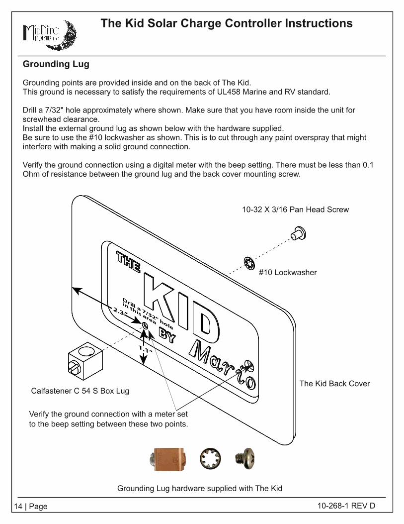
Grounding Lug
Grounding points are provided inside and on the back of The Kid.This ground is necessary to satisfy the requirements of UL458 Marine and RV standard.
Dri l l a 7/32" hole approximately where shown. Make sure that you have room inside the unit forscrewhead clearance.Instal l the external ground lug as shown below with the hardware supplied.Be sure to use the #1 0 lockwasher as shown. This is to cut through any paint overspray that mightinterfere with making a solid ground connection.
Verify the ground connection using a digital meter with the beep setting. There must be less than 0.1Ohm of resistance between the ground lug and the back cover mounting screw.
Grounding Lug hardware supplied with The Kid
1 0-32 X 3/1 6 Pan Head Screw
#1 0 Lockwasher
The Kid Back CoverCalfastener C 54 S Box Lug
Verify the ground connection with a meter setto the beep setting between these two points.
The Kid Solar Charge Controller Instructions
1 5 | Page 1 0-268-1 REV D
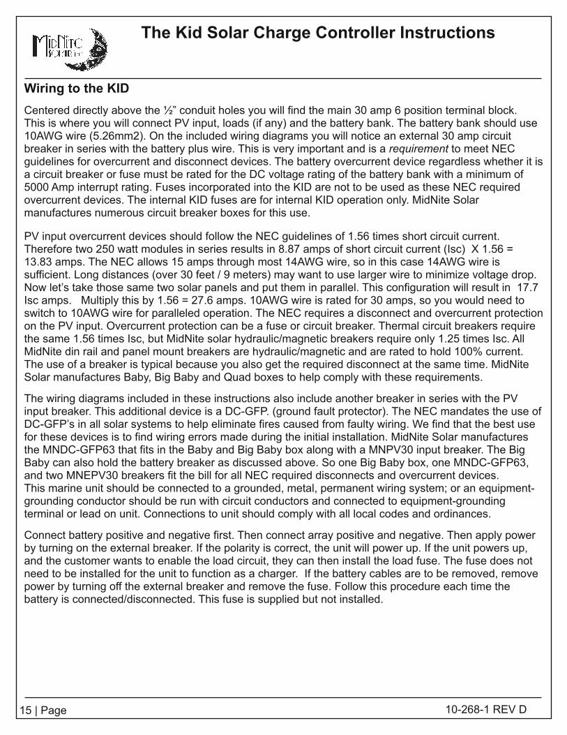
Wiring to the KID
Centered directly above the ½” conduit holes you wil l find the main 30 amp 6 position terminal block.This is where you wil l connect PV input, loads (if any) and the battery bank. The battery bank should use1 0AWG wire (5.26mm2). On the included wiring diagrams you wil l notice an external 30 amp circuitbreaker in series with the battery plus wire. This is very important and is a requirement to meet NECguidel ines for overcurrent and disconnect devices. The battery overcurrent device regardless whether it isa circuit breaker or fuse must be rated for the DC voltage rating of the battery bank with a minimum of5000 Amp interrupt rating. Fuses incorporated into the KID are not to be used as these NEC requiredovercurrent devices. The internal KID fuses are for internal KID operation only. MidNite Solarmanufactures numerous circuit breaker boxes for this use.
PV input overcurrent devices should fol low the NEC guidel ines of 1 .56 times short circuit current.Therefore two 250 watt modules in series results in 8.87 amps of short circuit current (Isc) X 1 .56 =1 3.83 amps. The NEC allows 1 5 amps through most 1 4AWG wire, so in this case 1 4AWG wire issufficient. Long distances (over 30 feet / 9 meters) may want to use larger wire to minimize voltage drop.Now let’s take those same two solar panels and put them in paral lel . This configuration wil l result in 1 7.7Isc amps. Multiply this by 1 .56 = 27.6 amps. 1 0AWG wire is rated for 30 amps, so you would need toswitch to 1 0AWG wire for paral leled operation. The NEC requires a disconnect and overcurrent protectionon the PV input. Overcurrent protection can be a fuse or circuit breaker. Thermal circuit breakers requirethe same 1 .56 times Isc, but MidNite solar hydraul ic/magnetic breakers require only 1 .25 times Isc. AllMidNite din rai l and panel mount breakers are hydraul ic/magnetic and are rated to hold 1 00% current.The use of a breaker is typical because you also get the required disconnect at the same time. MidNiteSolar manufactures Baby, Big Baby and Quad boxes to help comply with these requirements.
The wiring diagrams included in these instructions also include another breaker in series with the PVinput breaker. This additional device is a DC-GFP. (ground fault protector). The NEC mandates the use ofDC-GFP’s in al l solar systems to help el iminate fires caused from faulty wiring. We find that the best usefor these devices is to find wiring errors made during the initial instal lation. MidNite Solar manufacturesthe MNDC-GFP63 that fits in the Baby and Big Baby box along with a MNPV30 input breaker. The BigBaby can also hold the battery breaker as discussed above. So one Big Baby box, one MNDC-GFP63,and two MNEPV30 breakers fit the bil l for al l NEC required disconnects and overcurrent devices.This marine unit should be connected to a grounded, metal, permanent wiring system; or an equipment-grounding conductor should be run with circuit conductors and connected to equipment-groundingterminal or lead on unit. Connections to unit should comply with al l local codes and ordinances.
Connect battery positive and negative first. Then connect array positive and negative. Then apply powerby turning on the external breaker. I f the polarity is correct, the unit wil l power up. I f the unit powers up,and the customer wants to enable the load circuit, they can then instal l the load fuse. The fuse does notneed to be instal led for the unit to function as a charger. I f the battery cables are to be removed, removepower by turning off the external breaker and remove the fuse. Follow this procedure each time thebattery is connected/disconnected. This fuse is supplied but not instal led.
1 6 | Page 1 0-268-1 REV D
The Kid Solar Charge Controller Instructions
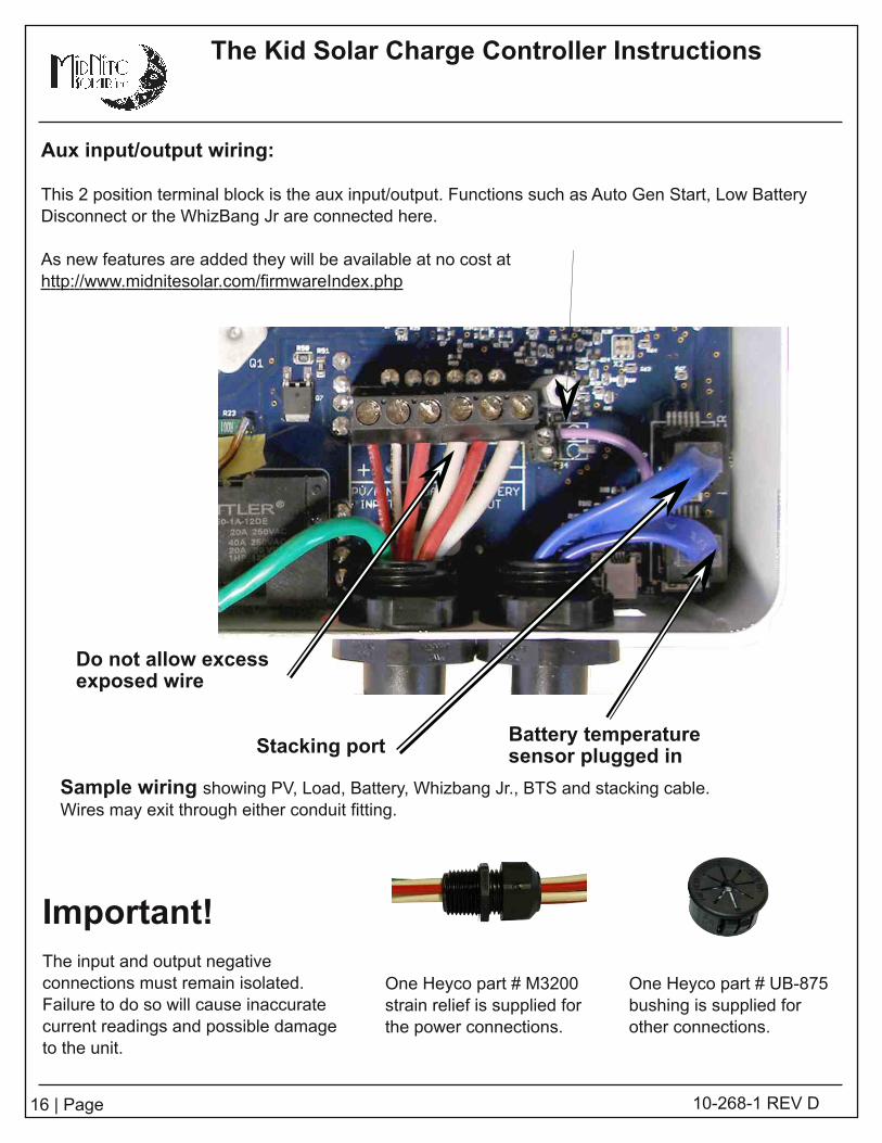
Aux input/output wiring:
This 2 position terminal block is the aux input/output. Functions such as Auto Gen Start, Low BatteryDisconnect or the WhizBang Jr are connected here.
As new features are added they wil l be available at no cost athttp: //www.midnitesolar.com/firmwareIndex.php
Stacking portBattery temperaturesensor plugged in
Do not allow excessexposed wire
Sample wiring showing PV, Load, Battery, Whizbang Jr. , BTS and stacking cable.Wires may exit through either conduit fitting.
One Heyco part # M3200strain rel ief is supplied forthe power connections.
Important!The input and output negativeconnections must remain isolated.Failure to do so wil l cause inaccuratecurrent readings and possible damageto the unit.
One Heyco part # UB-875bushing is supplied forother connections.

The Kid Solar Charge Controller Instructions
1 7 | Page 1 0-268-1 REV D
Chassis Ground connection
The screw, nut and terminal for grounding the chassis are included on all models.The chassis ground (equipment ground) is required in an NEC compliant system. The chassis of theKID is isolated from all internal KID circuitry.
Wiring the rest of the system :
Under the “Wiring diagrams” section of this manual there are seven different system configurations.1 2, 24 and 48VDC systems are shown. These diagrams are based on common solar panels ratedbetween 230 and 250 watts each, and a VOC of about 37 volts. (60 cell modules). These diagramscover 95% of all combinations that wil l be used with the KID. Other solar panels are available and cancertainly be used with the KID. Study the wiring diagrams to find the one that best suits your needs.You wil l see from 2 to 6 solar panels depending on system design and battery voltage. In a 1 2Vsystem you wil l be l imited to just two of these solar panels. The reason is that the KID has an absolutemaximum output of 30 amps. Power is amps X voltage, so 30 amps output times 1 4 volts (chargevoltage) = 420 watts. A 500 watt PV array would be a good match for a 1 2V system. You can alwaysstart with a smaller PV array and add to it at a later date. Keep in mind that PV voltage and currentneed to be matched closely in most cases. See the power graph at the end of this section. Batteryvoltage for the KID can be 1 2, 24 or 48 volts, so that means when you jump to a 24V battery bank, theKID can process twice the power than if it were connected to a 1 2V battery. In the case of a 48Vbattery, the KID can process 4 times the power of a 1 2V battery. Twelve volt batteries are used inmarine and RV and very small Renewable Energy systems. When possible, it is better to go with ahigher voltage battery bank, but that is usually not possible in a mobile application.

1 8 | Page 1 0-268-1 REV D
The Kid Solar Charge Controller Instructions
MNBTS Battery Temperature sensor
Standard on Marine versions, optional on All others. The published ratings of most batteries are madeat 77 degrees F (25°C). Mother nature as well as man doesn’t always allow the ambient temperature tohover around 25°C while charging batteries. Battery temperature sensors are employed on manysophisticated chargers in order to compensate the charge voltage based on temperature. I f you are inan area where the ambient temperature is relatively stable at this temperature, you do not need a BTS(Battery Temp Sensor). I f you l ive in Alaska or in the Sahara desert, you wil l want a BTS. I t wil l prolongthe l ife of your batteries. The BTS raises the charge voltage when colder than 77 degrees C anddecreases the charge voltage above 77 degrees F.
Temp comp is set for lead acid batteries, but is adjustable for other types in the Battery menu.
Twin Mode:
The KID stacking port is used for two things. When your power requirements grow and morecharging current is required, you can add a second KID and have it act l ike a 60 amp control ler. Thisrequires that the PV input and battery output be paral leled, You accomplish this outside of the KID ina suitable junction box. See page 21 for stacking set-up. Make sure to use wire and breakers ofsuitable size for each KID. Since you wil l now have a 60 amp output capabil ity, you might think that asingle 60 amp breaker after combining the output is acceptable? However, each KID accepts 1 0AWGwire max. A 60 amp breaker does not protect 1 0AWG wire, so two 30 amp breakers wil l be required.The same situation exists for the PV input. Make sure that wires are not too small for the overcurrentdevices.
1 4AWG = 1 5 amp breaker1 2AWG = 20 amp breaker1 0AWG = 30 amp breaker8AWG = 50 amp breaker6 AWG = 60 amp breaker
The Kid Solar Charge Controller Instructions
1 9 | Page 1 0-268-1 REV D
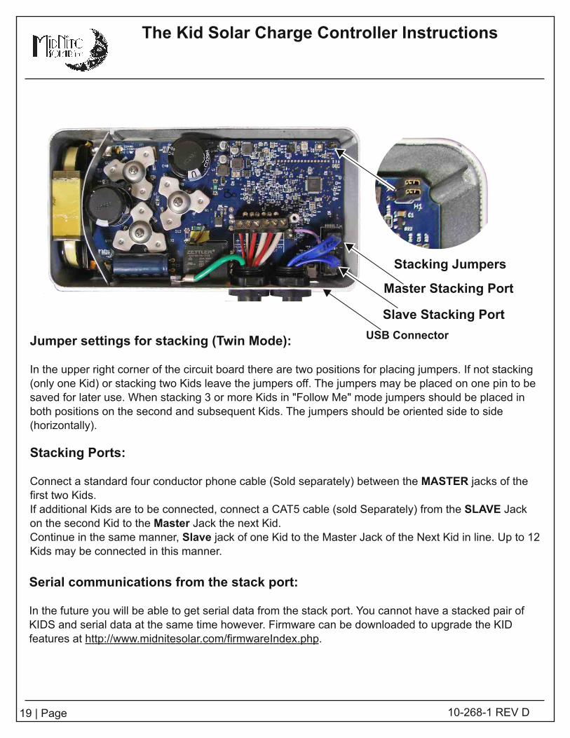
Stacking Jumpers
Master Stacking Port
Slave Stacking Port
Jumper settings for stacking (Twin Mode):
In the upper right corner of the circuit board there are two positions for placing jumpers. I f not stacking(only one Kid) or stacking two Kids leave the jumpers off. The jumpers may be placed on one pin to besaved for later use. When stacking 3 or more Kids in "Follow Me" mode jumpers should be placed inboth positions on the second and subsequent Kids. The jumpers should be oriented side to side(horizontal ly).
Stacking Ports:
Connect a standard four conductor phone cable (Sold separately) between the MASTER jacks of thefirst two Kids.I f additional Kids are to be connected, connect a CAT5 cable (sold Separately) from the SLAVE Jackon the second Kid to the Master Jack the next Kid.Continue in the same manner, Slave jack of one Kid to the Master Jack of the Next Kid in l ine. Up to 1 2Kids may be connected in this manner.
USB Connector
Serial communications from the stack port:
In the future you wil l be able to get serial data from the stack port. You cannot have a stacked pair ofKIDS and serial data at the same time however. Firmware can be downloaded to upgrade the KIDfeatures at http: //www.midnitesolar.com/firmwareIndex.php.
The Kid Solar Charge Controller Instructions
20 | Page 1 0-268-1 REV D
Set-Up and Use
These instructions are for firmware revision 1 795. New features are added frequently.
Now that your KID is al l wired up, solar panels in place and connected, battery bank instal led and anyloads connected, it is time to turn things on.
Get a digital meter. They can be had for as low as $4.00 at Harbor freight, so there is no excuse to nothave one. You wil l need one if support is ever required.
Check list:Make sure all breakers are off. You didn’t have them turned on while wiring did you?Measure the battery voltage to insure you don’t have a bad battery or bad connections. Read fromBattery plus to battery minus to get your nominal voltage. A 1 2V battery should read between 11 .5 and1 3.00. By the way if it does read below 1 2V, that is not a good sign! Then measure it again at the KIDterminals. I t should be the same as at the battery.
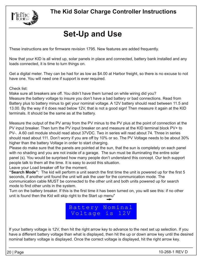
Measure the output of the PV array from the PV minus to the PV plus at the point of connection at thePV input breaker. Then turn the PV input breaker on and measure at the KID terminal block PV+ toPV-. A 60 cell module should read about 37VDC. Two in series wil l read about 74. Three in seriesshould read about 111 . Don’t worry if you are off by 1 0% or so. The PV Voltage needs to be about 30%higher than the battery Voltage in order to start charging.Please do make sure that the panels are pointed at the sun, that the sun is completely on each panelwith no shading and you are not inside of a garage. The sun must be il luminating the entire solarpanel (s). You would be surprised how many people don’t understand this concept. Our tech supportpeople talk to them all the time. I t is easy to avoid this situation.Leave your Load breaker off for the moment.“Search Mode” : The kid wil l perform a unit search the first time the unit is powered up for the first 5seconds, if another unit found the unit wil l ask the user for the communication mode. Thecommunication cable MUST be connected to the other unit and both units powered up for searchmode to find other units in the system.Turn on the battery breaker. I f this is the first time it has been turned on, you wil l see this: if no otherunit is found then the Kid wil l skip right to the Start up menu"
If your battery voltage is 1 2V, then hit the right arrow key to advance to the next set up selection. I f youhave a different battery voltage than what is displayed, then hit the up or down arrow key unti l the desirednominal battery voltage is displayed. Once the correct voltage is displayed, hit the right arrow key.
Battery NominalVoltage is 12V

21 | Page 1 0-268-1 REV D
The Kid Solar Charge Controller Instructions
The next set of screens are where you select battery type. Selecting the applicable battery type setssome important parameters that are specific to different battery chemistries. The first choice isFlooded. Use the up arrow to see all the choices. Listed below.
Stop on the correct battery type and then hit the right arrowkey. I t then takes you to the absorb voltage screen.
Battery TypeFlooded
Battery TypeAGM
Battery TypeGEL
Battery TypeCalcium
Battery TypeLithium
Battery TypeCustom
Battery Absorb14.3 Volts
The Kid Solar Charge Controller Instructions
22 | Page 1 0-268-1 REV D
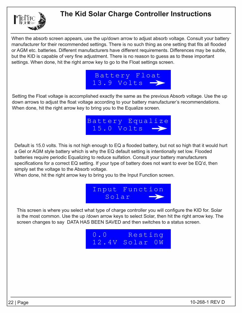
When the absorb screen appears, use the up/down arrow to adjust absorb voltage. Consult your batterymanufacturer for their recommended settings. There is no such thing as one setting that fits al l floodedor AGM etc. batteries. Different manufacturers have different requirements. Differences may be subtle,but the KID is capable of very fine adjustment. There is no reason to guess as to these importantsettings. When done, hit the right arrow key to go to the Float settings screen.
Setting the Float voltage is accomplished exactly the same as the previous Absorb voltage. Use the updown arrows to adjust the float voltage according to your battery manufacturer’s recommendations.When done, hit the right arrow key to bring you to the Equalize screen.
Default is 1 5.0 volts. This is not high enough to EQ a flooded battery, but not so high that it would hurta Gel or AGM style battery which is why the EQ default setting is intentional ly set low. Floodedbatteries require periodic Equalizing to reduce sulfation. Consult your battery manufacturersspecifications for a correct EQ setting. I f your type of battery does not want to ever be EQ’d, thensimply set the voltage to the Absorb voltage.When done, hit the right arrow key to bring you to the Input Function screen.
This screen is where you select what type of charge control ler you wil l configure the KID for. Solaris the most common. Use the up /down arrow keys to select Solar, then hit the right arrow key. Thescreen changes to say DATA HAS BEEN SAVED and then switches to a status screen.
Battery Float13.9 Volts
Battery Equalize15.0 Volts
Input FunctionSolar
0.0 Resting12.4V Solar 0W

23 | Page 1 0-268-1 REV D
The Kid Solar Charge Controller Instructions
STATUS BUTTON: There are a few status screens available at the touch of the Status button.The first (left) screen shows:
The 9.5a as depicted above represents the battery output current.BULKMPPT shows the state that the charger is in. BULKMPPT means the KID is going all out to put al lavailable energy into the batteries.The 1 2.7V represents battery voltage.The SOLAR shows it is in Solar mode.The 257W shows the instantaneous wattage going into the battery.push the right arrow key to bring up the second status screen shown below.
This second status screen is showing the PV array voltage and battery voltage. The PV array voltagecorresponds to the Max power voltage from the PV array for the present conditions.Push the right arrow key to bring up the third status screen.
This third status screen is showing input from the WBJr. . In this display 9.5 amps are going to thebatteries, State of Charge is 93% and 372 Amp hours remain in the batteries.Push the right arrow key to bring up the fourth status screen.
9.5A BULKMPPT12.7 Solar 257W
Input Battery59.6V 13.5V
9.5a SOC 93%372Ah Remaining
KWhr Kid Ahr0.0 0.0
Load: Manual0.0a Off
This fourth status screen is showing what mode the Load is in, the current that the load is drawing andwhether the load is on or off.Push the right arrow key to bring up the fifth status screen.
This fifth status screen is showing daily power produced in Kilowatt hours and Amphours.

The Kid Solar Charge Controller Instructions
24 | Page 1 0-268-1 REV D
0.0A Resting13.7 Solar 0W
Input Battery5.4V 13.7V
0.0a SOC 100%400Ah Remaining
Load: Manual0.0a Off
KWhr KID Ahr0.0 0.0
0.0A Resting13.7 Solar 0W
Input Battery5.4V 13.7V
0.0a SOC 100%400Ah Remaining
CPU FET Batt25c 23c 23c
KWhr KID Ahr0.0 0.0
Status Screens.
The Kid has several status display screens showing voltage, charge mode, temperatures, currentsand voltages. These screens are displayed any time that the LCD is on and you are not in a menu.I f you press the STATUS button the fol lowing screens wil l be displayed. The first screen is displayedby default and the others are available by pressing the right arrow. The left arrow wil l step backthrough the status display screens.
When The Kid has been idle for five minutes the display wil l cycle through the fol lowing screens.Each screen wil l display for a few seconds and then advance to the next.You may push the arrow keys anytime while The Kid is cycling through these screens to return tomanually stepping through the status screens shown above. The STATUS and MENU BACK buttonsare always available. Scrol l ing may be disabled in the LCD Menu.

25 | Page 1 0-268-1 REV D
The Kid Solar Charge Controller Instructions
The Kid's L.E.D.s.
RFC - Received Full Charge. Thebattery has received a ful l charge.
1WK - One Week. I t has been oneweek since a ful l charge.
2WK - Two Weeks. I t has been twoweeks since a ful l charge.
FLT - Float. The battery is in floatcharge.OVR - Over Voltage. The kid hasdetected an overvoltage.ERR - Error. The kid has stopped dueto an error or generator did not start.CLP - Displays Load On/Off.
The Kid has several L.E.D.s to indicatemodes and errors.
LEDs
SETUP
STATUS
ENTER SAVE
MENUBACK
The Kid's Keypad
Arrow Keys

26 | Page 1 0-268-1 REV D
The Kid Solar Charge Controller Instructions
MAIN MENUS:
The KID has 7 MAIN MENU headings. This section deals with the MAIN MENU headings only.See INSIDE THE MAIN MENUS for what is inside each of the 7 menus.
Hit the MENU/BACK key. This button takes you to all of the Main Menus. Main menus are somethingyou want to become famil iar with. No matter where you are at in any menu, you can always get to theMain Menus by hitting this button once or twice.You scrol l through Main Menus from left to right. The left most Main Menu is as fol lows.
Notice the word BATTERY is in brackets. That means the BATTERY menu wil l be activated if theENTER button is pushed. The BATTERY menu allows you to set al l battery charging parameters justl ike what was done in the initial set up.The BATTERY menu has additional adjustments beyond what the initial set up had. After the first timeactivating the KID, this is the way to change Battery charging parameters.The adjustments and settings available inside the BATTERY menu are:
Absorb voltage settingsFloat voltage settingsEqualize voltage settingsAmp limits for battery charging and load drawTemperature compensation adjustabil ityTemp comp during EQ
Adjust Setpoint<Battery> Load
Manual EQ:Note: Auto EQ is not available on The Kid.Manual EQ allows the user to trigger an Equalize (EQ) cycle manually.There are two parameters to set before you can equalize, EQ voltage and EQ time.Refer to the battery manufacturer's recommendations for equalizing voltages and times.
To set EQ parameters:Press Main Menu and select Battery,Go to EQ and press Enter,Press the SETUP Button to adjust the EQ Voltage and Time.
To start a manual EQ cycle:Press Main Menu and select Battery,Go to EQ and press Enter,Select START,The EQ Cycle wil l begin.

The Kid Solar Charge Controller Instructions
27 | Page 1 0-268-1 REV D
Battery Charge Stages and Meanings
Bulk MPPTThis stage of The Kid means; that The Kid wil l be putting out as much current as it can trying to chargethe batteries to the absorb voltage set point. This is also known as constant current mode.
AbsorbThis stage means that The Kid wil l maintain the absorb set point voltage unti l the batteries are chargedor it reaches Float stage. At this stage The Kid is not putting out maximum current, as that wouldincrease the battery voltage over the Absorb set point. This is also referred to as constant voltagemode. The battery is considered “ful l” at the end of the absorb charge cycle.
The absorb time is proportional to the bulk time. (i .e. the time bulk takes to reach the absorb voltage.)The battery it’s considered “ful l” at the end of the absorb charge cycle.
FloatA Float cycle fol lows after the Absorb cycle is completed; Float is displayed on the screen. Battery volt-age is held at the float voltage set point, float time can be changed by the user.
EqualizeThe intent of an equalization charge is to bring al l battery cells to an equal voltage by a deliberateovercharge. The goal is to return each battery cell to its optimum condition through a series of voltagecontrol led chemical reactions inside the batteries.
28 | Page 1 0-268-1 REV D
The Kid Solar Charge Controller Instructions
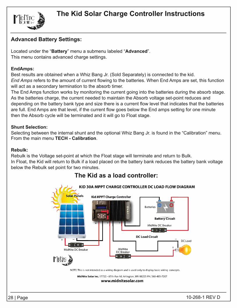
Advanced Battery Settings:
Located under the “Battery” menu a submenu labeled “Advanced”.This menu contains advanced charge settings.
EndAmps:Best results are obtained when a Whiz Bang Jr. (Sold Separately) is connected to the kid.End Amps refers to the amount of current flowing to the batteries. When End Amps are set, this functionwil l act as a secondary termination to the absorb timer.The End Amps function works by monitoring the current going into the batteries during the absorb stage.As the batteries charge, the current needed to maintain the Absorb voltage set-point reduces anddepending on the battery bank type and size there is a current flow level that indicates that the batteriesare ful l . End Amps are that level, if the current flow goes below the End amps setting for one minutethen the Absorb cycle wil l be terminated and it wil l go to Float stage.
Shunt Selection:Selecting between the internal shunt and the optional Whiz Bang Jr. is found in the “Calibration” menu.From the main menu TECH - Calibration .
Rebulk:Rebulk is the Voltage set-point at which the Float stage wil l terminate and return to Bulk.In Float, the Kid wil l return to Bulk if a load placed on the battery bank reduces the battery bank voltagebelow the Rebulk set point for two minutes.
The Kid as a load controller:
The Kid Solar Charge Controller Instructions
29 | Page 1 0-268-1 REV D
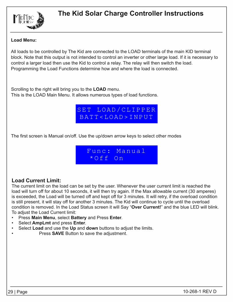
Scroll ing to the right wil l bring you to the LOAD menu.This is the LOAD Main Menu. I t al lows numerous types of load functions.
Load Menu:
All loads to be control led by The Kid are connected to the LOAD terminals of the main KID terminalblock. Note that this output is not intended to control an inverter or other large load. I f it is necessary tocontrol a larger load then use the Kid to control a relay. The relay wil l then switch the load.Programming the Load Functions determine how and where the load is connected.
The first screen is Manual on/off. Use the up/down arrow keys to select other modes
SET LOAD/CLIPPERBATT<LOAD>INPUT
Func: Manual*Off On
Load Current Limit:The current l imit on the load can be set by the user. Whenever the user current l imit is reached theload wil l turn off for about 1 0 seconds, it wil l then try again. I f the Max allowable current (30 amperes)is exceeded, the Load wil l be turned off and kept off for 3 minutes. I t wil l retry, if the overload conditionis sti l l present, it wil l stay off for another 3 minutes. The Kid wil l continue to cycle unti l the overloadcondition is removed. In the Load Status screen it wil l Say “Over Current! ” and the blue LED wil l bl ink.To adjust the Load Current l imit:• Press Main Menu , select Battery and Press Enter.• Select AmpLmt and press Enter.• Select Load and use the Up and down buttons to adjust the l imits.• Press SAVE Button to save the adjustment.

The Kid Solar Charge Controller Instructions
30 | Page 1 0-268-1 REV D
Load Control Modes
The load control output is a very versati le feature. Some of the basic uses are explained here.
● Manual Mode - The load is turned on and off manually from the Kid control panel. The load wil l alsodisconnect when the low voltage disconnect setting is reached.
● Dusk + Time - In this mode the load is turned on at dusk. The load then remains on for the amount oftime selected. The solar clock helps determine when dusk is and adjusts for the seasons.
● Night Light - When selected the load is turned on at dusk and off at dawn.
● Day Light - When selected the load is turned on at dawn and off at dusk.
● PWM Divert - This mode wil l maintain three stage charging while making excess power available tothe load.
● Float On - In this mode the load is turned on when the batteries go to float.
● Float Off - In this mode the load is turned off when the batteries go to float.
● Diversion - When there is more power available than the batteries can use this excess power can beused to run opportunity loads.
● Toggle - This is a test mode. The load wil l be turned on and off twice per second.
● NightVarOFF - The load wil l be turn on at dusk and it wil l stay on for the time specified. The load wil lthen turn on the specified hours before dawn, turning off again at dawn.
● Hourly - In this mode the loads are turned on and off based on time of day. The Kid's internal clock isadjusted daily based on sunrise and sunset times and is approximate.
Every night the clock re-adjusts the time by using the PV panels to detect dusk and dawn, the time isonly an estimate and it does not take into account Daylight Savings Time.
For example, if in spring you set The Kid to turn the load on at 6:00 P.M. and off at 8:00 P.M. and duskis at 5:30 P.M. The load would turn on at 6:00 P.M. and would turn off at 8:00 P.M.
As the sunset time gets later than the turn on time, the turn on time would then be at dusk and the turnoff time wil l remain at 8:00. Should dusk come after 8:00 P.M. the load would not come on.
On that sad, sad day after the solstice when the daylight hours start getting shorter again, as duskreturns to 6:00 P.M. or earl ier the turn on time would again be 6:00 P.M. The turn offtime wil l remain at 8:00 PM while dusk could be at 5:1 3 or earl ier.
To select the on time and off times press MENU BACK, select LOAD and press the up arrow unti l thedisplay shows HOURLY then press SETUP.
31 | Page 1 0-268-1 REV D
The Kid Solar Charge Controller Instructions
Load Functions detailed Description
-FUNC: Manual - ON/OFF - This Mode can be turned On or Off by the user Manually, and the Loadcircuit wil l act accordingly, this Mode can be Used with the Low Battery Disconnect safety monitoring.
To use Manual Mode:• From the Status Menu: Press Menu Back• Scrol l to the Right and select Load and Press Enter• Select FUNC: Manual• Press the Right button to *ON - The load wil l turn on and stay on unti l turned off.• Press the Save Button• Press SETUP button to Bring up LBD setup (see LBD Low Battery D isconnect for more detai ls).
-FUNC: Dusk + Hrs - OFF/AUTO - This Function wil l become active when night comes and it wil l stayOn for the number of hrs set up by the user, then the load wil l turn Off.To use Dusk + Hrs:• From the Status Menu: Press Menu Back• Scrol l to the Right and select Load and Press Enter• Select FUNC: Dusk + Hrs• Press the Right button to *AUTO - The load wil l turn on and off as set by the user.• Press the Save Button• Press SETUP button adjust the amount of Hrs to stay on.• Press the Save Button
-FUNC: Night Light – OFF/AUTO – This function wil l turn on the load when night comes and it wil l turnit off when the sun comes up, this Mode can be Used with the Low Battery Disconnect safetymonitoring.To use Night Light Mode:• From the Status Menu: Press Menu Back• Scrol l to the Right and select Load and Press Enter• Select FUNC: Night Light• Press the Right button to *Auto• Press the Save Button• Press SETUP button to Bring up LBD setup (see LBD section for more detai ls).
-FUNC: Day Light – OFF/AUTO – This function wil l turn on the load when the sun comes up and it wil lturn off when the sun goes down, this Mode can be Used with the Low Battery Disconnect safetymonitoring.To use Day Light Mode:• From the Status Menu: Press Menu Back• Scrol l to the Right and select Load and Press Enter• Select FUNC: Day Light• Press the Right button to *Auto• Press the Save Button• Press SETUP button to Bring up LBD setup (see LBD section for more detai ls).
-FUNC: PWM Divert – OFF/AUTO – This function wil l divert excess power to the load when extra

The Kid Solar Charge Controller Instructions
32 | Page 1 0-268-1 REV D
power is available and it wil l maintain 3 stage battery charging. There are 2 parameters that can beadjusted when Pressing the SETUP button; Offset and WidthOffset: This is in voltage, and refers to an Offset from the current battery voltage Set point, for example ifthe battery charging stage is Absorb then the Offset is taken from the Absorb set point, in the samemanner it wil l be taken from the other Stages also it takes into account if the Battery temperature sensoris plugged in and set up.Width: This is in voltage and refers to the volts the transition wil l take, from On to Off and vise-versa.To use PWM Divert Mode do the Following:• From the Status Menu: Press Menu Back• Scrol l to the Right and select Load and Press Enter• Select FUNC: PWM Divert• Press the Right button to *ON• Press the Save Button• Press SETUP button to adjust the Offset and Width set points.
- FUNC: Float ON: The Load wil l be turned on when the battery state of charge is Float and it wil lturn off when the state of charge is any other than FloatTo use Float On Mode do the Following:• From the Status Menu: Press Menu Back• Scrol l to the Right and select Load and Press Enter• Select FUNC: Float On• Press the Right button to *Auto• Press the Save Button
- FUNC: Float OFF: The Load wil l be turned off when the battery state of charge is Float and it wil lturn on when the state of charge is any other than FloatTo use Float Off Mode do the Following:• From the Status Menu: Press Menu Back• Scrol l to the Right and select Load and Press Enter• Select FUNC: Float Off• Press the Right button to *Auto• Press the Save Button
-FUNC: Diversion – OFF/AUTO – This function wil l divert excess power to the load when extra power isavailable. This mode is not PWM based. There are 2 parameters that can be adjusted when Pressingthe SETUP button; VoltOn and VoltOffVoltsOn: This is the absolute voltage, at which the load wil l be turned onVoltsOff: This is the absolute voltage, at which the load wil l be turned offTo use Diversion Mode do the Following:• From the Status Menu: Press Menu Back• Scrol l to the Right and select Load and Press Enter• Select FUNC: Diversion• Press the Right button to *ON• Press the Save Button• Press SETUP button to adjust the VoltsOn and VoltsOff set points.
-FUNC: Toggle Test – OFF/AUTO – This Mode is for testing purposes only, it wil l turn the load On and

33 | Page 1 0-268-1 REV D
The Kid Solar Charge Controller Instructions
Off at twice per second.
-FUNC: LVD Alarm – OFF/AUTO - This mode wil l turn on if the battery voltage goes below the AlrmONset point and turn OFF if it goes above the AlrmOFF Set point.• From the Status Menu: Press Menu Back• Scrol l to the Right and select Load and Press Enter• Select FUNC: LVD Alarm• Press the Right button to *ON• Press the Save Button• Press SETUP button to adjust the VoltsOn and VoltsOff set points.Note: the AlrmOn/AlrmOFF setpoints are independent from those on the AUX Port.
-FUNC: NightVarOff – OFF/AUTO - Turns the load on for a user selected amount of time after dusk andbefore dawn.• From the Status Menu: Press Menu Back• Scrol l to the Right and select Load and Press Enter• Select FUNC: NightVarOff• Press the Right button to *Auto• Press the Save Button• Press SETUP button to adjust the how long after dusk and before dawn the load wil l be turned on.
-FUNC: Hourly – OFF/AUTO - In this mode the clock re-adjusts the time every night by using the PVpanels to detect dusk and dawn, the time it is only an estimate and it does not take into account DST.• From the Status Menu: Press Menu Back• Scrol l to the Right and select Load and Press Enter• Select FUNC: Hourly• Press the Right button to *Auto• Press the Save Button• Press SETUP button to set the time the load wil l turn on and off.
LBD - Low Battery Disconnect:
The kid includes an adjustable Low battery Disconnect function which allows the user to set an absolutedischarge limit when using a daily function such as Night Light and the l ife of the batteries doesn't wantto be compromised, it also includes a reconnect voltage set point or it could be reconnected when Floathas been reached, ensuring that the batteries have been ful ly charged after a LBD (Low BatteryDisconnect).I f a LBD state has occurred the blue LED wil l bl ink slowly.
To set up these parameters:-Press Menu Back button-Scrol l to the right and select <Load> and press Enter-Press the Setup button-I f OFF appears under the names Lowbatt and Reconn it means the feature is currently disabled.-Press the Right button to enable the function, now two numbers wil l appear under the names-Press the Left, Right, Up and Down keys to adjust the voltages as needed for your battery type-To enable reconnect on Float stage go to Reconn and Press the Right key again and the word FLOAT
The Kid Solar Charge Controller Instructions
34 | Page 1 0-268-1 REV D
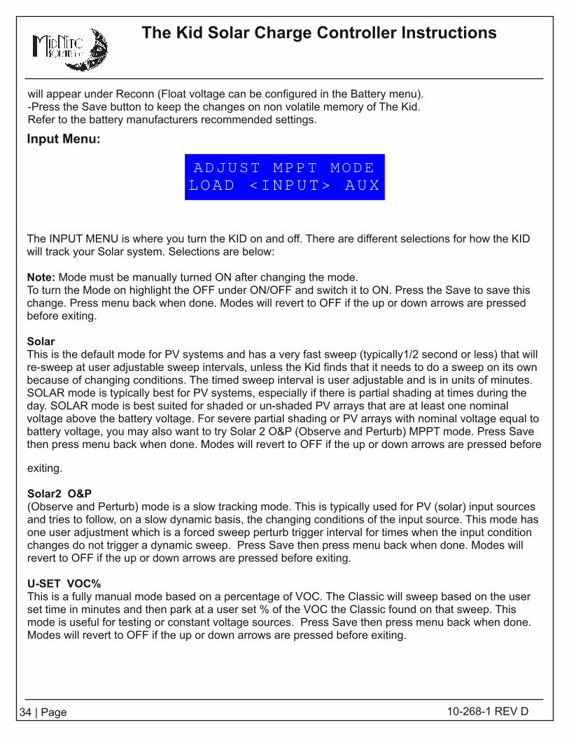
The INPUT MENU is where you turn the KID on and off. There are different selections for how the KIDwil l track your Solar system. Selections are below:
Note: Mode must be manually turned ON after changing the mode.To turn the Mode on highl ight the OFF under ON/OFF and switch it to ON. Press the Save to save thischange. Press menu back when done. Modes wil l revert to OFF if the up or down arrows are pressedbefore exiting.
SolarThis is the default mode for PV systems and has a very fast sweep (typical ly1 /2 second or less) that wil lre-sweep at user adjustable sweep intervals, unless the Kid finds that it needs to do a sweep on its ownbecause of changing conditions. The timed sweep interval is user adjustable and is in units of minutes.SOLAR mode is typical ly best for PV systems, especial ly if there is partial shading at times during theday. SOLAR mode is best suited for shaded or un-shaded PV arrays that are at least one nominalvoltage above the battery voltage. For severe partial shading or PV arrays with nominal voltage equal tobattery voltage, you may also want to try Solar 2 O&P (Observe and Perturb) MPPT mode. Press Savethen press menu back when done. Modes wil l revert to OFF if the up or down arrows are pressed before
Input Menu:
exiting.
Solar2 O&P(Observe and Perturb) mode is a slow tracking mode. This is typical ly used for PV (solar) input sourcesand tries to fol low, on a slow dynamic basis, the changing conditions of the input source. This mode hasone user adjustment which is a forced sweep perturb trigger interval for times when the input conditionchanges do not trigger a dynamic sweep. Press Save then press menu back when done. Modes wil lrevert to OFF if the up or down arrows are pressed before exiting.
U-SET VOC%This is a ful ly manual mode based on a percentage of VOC. The Classic wil l sweep based on the userset time in minutes and then park at a user set % of the VOC the Classic found on that sweep. Thismode is useful for testing or constant voltage sources. Press Save then press menu back when done.Modes wil l revert to OFF if the up or down arrows are pressed before exiting.
ADJUST MPPT MODELOAD <INPUT> AUX
wil l appear under Reconn (Float voltage can be configured in the Battery menu).-Press the Save button to keep the changes on non volati le memory of The Kid.Refer to the battery manufacturers recommended settings.

35 | Page 1 0-268-1 REV D
The Kid Solar Charge Controller Instructions
The AUX menu is where you set up various auxil iary input and output functions such as Auto Genstart,Low Battery Disconnect and the Whizbang Jr. Battery status monitor.
Hit the right arrow to advance to the AUX MAIN MENU .
Note: Mode must be manually turned ON after changing the mode.To turn the Mode on highl ight the OFF under ON/OFF and switch it to ON. Press the Save to save thischange. Press menu back when done. Modes wil l revert to OFF if the up or down arrows are pressedbefore exiting.
FUNC: WBJR OFF/AUTO - Enable/Disable/Setup the WBJR• From the Status Menu: Press Menu Back• Scrol l to the Right and select AUX and Press Enter• Select FUNC:WBJR• Press the Right button to Auto.• Press the Save Button• Press SETUP button to set the Battery Capacity.
scrol l to the right to set Battery Efficiency.Scrol l right to set the Battery Temp Ref.Scrol l right to set the Battery Change %.
• Press the Save Button.
FUNC: Gen Start OFF/AUTO/ON - Enable/Disable/Setup Auto Generator StaringTo use Gen Start:• From the Status Menu: Press Menu Back• Scrol l to the Right and select AUX and Press Enter• Select FUNC:Gen Start• Press the Right button to Auto or *ON• Press the Save Button• Press SETUP button to set the battery voltage threshold to start the generator.
scrol l to the right to set the Gen Start delay.Scrol l right to set the Min Gen Runtime.Scrol l right to set the Max Gen Runtime.Scrol l right to set the Gen Run Confirm Voltage.
• Press the Save Button
FUNC: LBD High OFF/AUTO - Enable/Disable/Setup Low Battery Disconnect High• From the Status Menu: Press Menu Back• Scrol l to the Right and select AUX and Press Enter• Select FUNC:LBD High• Press the Right button to Auto.• Press the Save Button• Press SETUP button to set the AlrmON Voltage. scrol l to the right to set AlrmOFF Voltage.• Press the Save Button.
SETUP AUX FUNCTIONLOAD <AUX> MISC

The Kid Solar Charge Controller Instructions
36 | Page 1 0-268-1 REV D
The MISC menu allows adjustment for:LCD - Backlight and contrast controls can be adjusted with the up/down buttonsTemp - Status of CPU, FET and Battery in degrees CLEDS - Rick mode (minimal l ights) and OffTimer - Shows time accrued.Password - Enable/Disable Password
Hit the right arrow key to advance to the COMM menu.
The COMM menu is where stacking is set up. Your choices are Twin Mode and Sync.Note: On earl ier units Twin Mode was known as BullyMode and Sync Mode was known as Follow Me.
Twin Mode: is true paral lel ing where the inputs and outputs are paral leled. You are allowed only twoKIDS in Twin mode. This is a Master/Slave configuration. The Master Twin tel ls the second Kid what todo. Sync Mode is where the outputs are paral leled, but each input has its own PV array. Twin modeonly works when two kids are connected.
Sync Mode: When any one of the KIDs change state, Absorb, Time, Float or Equalize it sends a signaldownstream to the next one to fol low and change state. Then the second one sends the samemessage downstream and so on unti l i t final ly comes back around the communications circle and allunits are in the new state. There is no limit to how many control lers can be connected in Sync mode.Both Sync and Twin mode are MidNite Solar exclusive methods of applying multiple control lers.
Hit the right arrow key to advance to the MISC menu.
FUNC: LBD Low OFF/AUTO - Enable/Disable/Setup Low Battery Disconnect High• From the Status Menu: Press Menu Back• Scrol l to the Right and select AUX and Press Enter• Select FUNC:LBD Low• Press the Right button to Auto.• Press the Save Button• Press SETUP button to set the AlrmON Voltage. scrol l to the right to set AlrmOFF Voltage.• Press the Save Button.
OTHER STUFFAUX <MISC> COMM
MULTIPLE UNITSMISC <COMM> TECH

The Kid Solar Charge Controller Instructions
37 | Page 1 0-268-1 REV D
*Use the Up and Down buttons to adjust to the desired setting*Press the SAVE button to keep the settings.
Input V OFFSET - Adjusts the PV voltage display on The Kid to match a digital multi-meter.
To adjust the settings:*Press Menu back*Scrol l to the right then select TECH and press Enter*Select Calibrate and press Enter*Press the left/right arrow unti l Input V OFFSET is on the top line of the LCD*Use the Up and Down buttons to adjust to the desired setting*Press the SAVE button to keep the settings.
AntiClick Sensitivity:This setting refers to the input voltage from the panels that the Kid wil l sweep down to from VOC whentrying to figure out if there is enough power for the unit to turn on, the higher the number is set to theless the relay wil l cl ick(less sensitive) at sunrise and sunset, but if the number is set too high then, theunit might not turn on even when there is enough power available to charge the batteries. The lower
Hit the right arrow key to advance to the TECH menu. The TECH menu is for tech savvy individuals.
Calibrate: You can calibrate the battery voltage offset as well as the Input voltage offset to read thesame as your Fluke meter. In this menu you may also set/adjust - Anti Cl ick Sensitivity, EndAmp ShuntSel, Pre Matching, Min Low Power and NightLight on PV.
Calibrate Menu:
Battery V OFFSET - Adjusts the battery voltage display on The Kid to match a digital multi-meter.Input V OFFSET - Adjusts the PV voltage display on The Kid to match a digital multi-meter.AntiClick Sensit: - Adjusts the input threshold at which The Kid starts charging.EndAmp Shunt Sel: - Selects between The Kid's internal shunt and the (optional) WBJr's shunt.Pre Matching: This setting is to be only changed from the default value if indicated by a MidNite SolarTech, the default Value is 0.8Min Low Power: The minimum power the unit has to be producing to be kept on, default is 1 0 watts.NightLight on PV: - Adjusts The Kid's night detection. Helpful when lights shine on the panels at night.
Battery V OFFSET - Adjusts the battery voltage display on The Kid to match a digital multi-meter.
To adjust the settings:*Press Menu back*Scrol l to the right then select TECH and press Enter*Select Calibrate and press Enter*Press the left/right arrow unti l Battery V OFFSET is on the top line of the LCD
ADVANCED MENUCOMM <TECH>

38 | Page 1 0-268-1 REV D
The Kid Solar Charge Controller Instructions
that the number is set the unit wil l cl ick more frequently, and may turn on sooner (with less poweravailable). I f you do not understand this setting, do not change from the factory default setting (8.0),unless instructed from MidNite Solar personal Tech Support.
To adjust the settings:*Press Menu Back*Scrol l to the right then select TECH and press Enter*Select Calibrate and press Enter*Press the right arrow unti l AntiCl ick Sensitivity is on the top line of the LCD*Use the Up and Down buttons to adjust to the desired setting*Press the SAVE button to keep the settings.
EndAmp Shunt Sel: - Selects between The Kid's internal shunt and the (optional) WBJr's shunt.
To adjust the settings:*Press Menu Back*Scrol l to the right then select TECH and press Enter*Select Calibrate and press Enter*Press the right arrow unti l EndAmp Shunt Sel is on the top line of the LCD*Use the Up and Down buttons to adjust to the desired setting*Press the SAVE button to keep the settings.
Pre Matching:
To adjust the settings:*Press Menu Back*Scrol l to the right then select TECH and press Enter*Select Calibrate and press Enter*Press the right arrow unti l Pre Matching is on the top line of the LCD*Use the Up and Down buttons to adjust to the desired setting*Press the SAVE button to keep the settings.Do not adjust this setting unless directed to do so by MidNite Solar Tech Support.
Min Low Power:
To adjust the settings:*Press Menu Back*Scrol l to the right then select TECH and press Enter*Select Calibrate and press Enter*Press the right arrow unti l Min Low Power is on the top line of the LCD*Use the Up and Down buttons to adjust to the desired setting*Press the SAVE button to keep the settings.
NightLight on PV: This setting is for adjusting The Kid's sensitivity to ambient l ight.In the event that your night l ights shine on the panels this setting adjusts the threshold of l ight required to
The Kid Solar Charge Controller Instructions
39 | Page 1 0-268-1 REV D
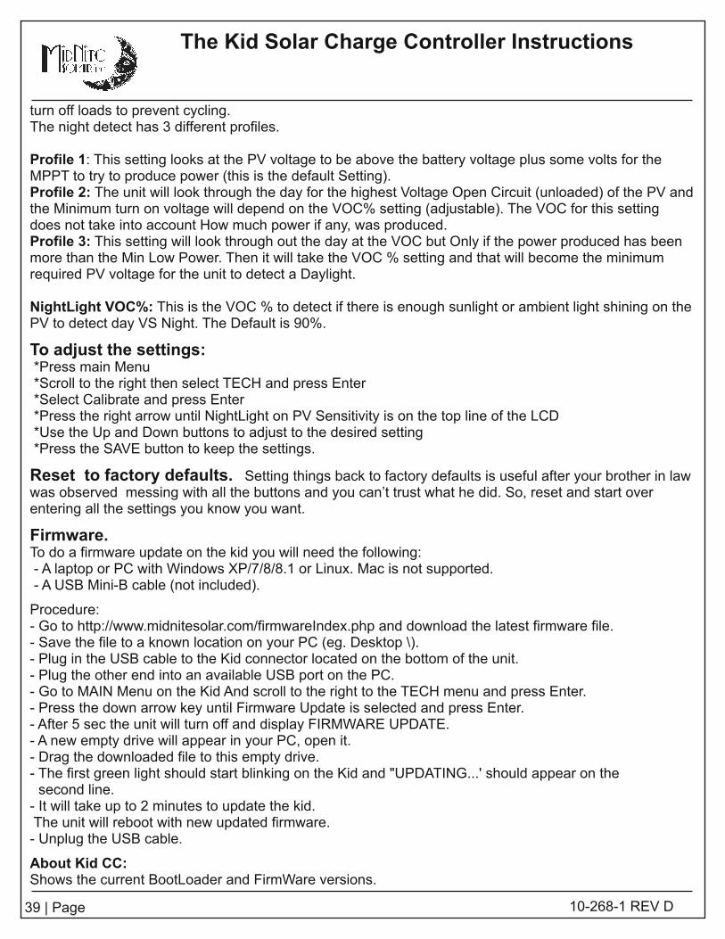
turn off loads to prevent cycling.The night detect has 3 different profi les.
Profile 1 : This setting looks at the PV voltage to be above the battery voltage plus some volts for theMPPT to try to produce power (this is the default Setting).Profile 2: The unit wil l look through the day for the highest Voltage Open Circuit (unloaded) of the PV andthe Minimum turn on voltage wil l depend on the VOC% setting (adjustable). The VOC for this settingdoes not take into account How much power if any, was produced.Profile 3: This setting wil l look through out the day at the VOC but Only if the power produced has beenmore than the Min Low Power. Then it wil l take the VOC % setting and that wil l become the minimumrequired PV voltage for the unit to detect a Daylight.
NightLight VOC%: This is the VOC % to detect if there is enough sunlight or ambient l ight shining on thePV to detect day VS Night. The Default is 90%.
To adjust the settings:*Press main Menu*Scrol l to the right then select TECH and press Enter*Select Calibrate and press Enter*Press the right arrow unti l NightLight on PV Sensitivity is on the top line of the LCD*Use the Up and Down buttons to adjust to the desired setting*Press the SAVE button to keep the settings.
Reset to factory defaults. Setting things back to factory defaults is useful after your brother in lawwas observed messing with al l the buttons and you can’t trust what he did. So, reset and start overentering al l the settings you know you want.
Firmware.To do a firmware update on the kid you wil l need the fol lowing:- A laptop or PC with Windows XP/7/8/8.1 or Linux. Mac is not supported.- A USB Mini-B cable (not included).
Procedure:- Go to http: //www.midnitesolar.com/firmwareIndex.php and download the latest firmware fi le.- Save the fi le to a known location on your PC (eg. Desktop \).- Plug in the USB cable to the Kid connector located on the bottom of the unit.- Plug the other end into an available USB port on the PC.- Go to MAIN Menu on the Kid And scrol l to the right to the TECH menu and press Enter.- Press the down arrow key unti l Firmware Update is selected and press Enter.- After 5 sec the unit wil l turn off and display FIRMWARE UPDATE.- A new empty drive wil l appear in your PC, open it.- Drag the downloaded fi le to this empty drive.- The first green light should start bl inking on the Kid and "UPDATING.. . ' should appear on thesecond line.- I t wil l take up to 2 minutes to update the kid.The unit wil l reboot with new updated firmware.- Unplug the USB cable.
About Kid CC:Shows the current BootLoader and FirmWare versions.

The Kid Solar Charge Controller Instructions
40 | Page 1 0-268-1 REV D
Auto Gen Start (AGS) – This function wil l try to start the Generator and while monitoring batteryvoltage to assure the generator is charging. I f not, it wil l signal the generator to shut down toconserve fuel.
Generator On at: Battery voltage level that wil l trigger the signal to start the generator.
GenStart Delay: Delay in minutes that the battery voltage must be below the“Generator On at” setting ,To signal the generator to start.
MIN Gen Run Time: Minimum time in minutes the generator wil l run after Auto Gen Start.
MAX Gen Run Time: Maximum time in minutes the generator wil l run after Auto Gen Start.
Gen Run Confirm: When battery voltage and time requirements for Auto Gen Start have beenmet, the Input mode wil l be turned off for a “Qualifying time”period.During this time the kid wil l look at the battery voltage to see if it hasreached the Gen Run Confirm voltage. I f successful the gen run signal wil lbe kept on for at least the minimum run time. I f this voltage is not reachedthen the run signal to the Generator wil l be turned off and a warning LEDwil l be turned on. In either case the Input mode wil l be turned back onafter the qualifying time period.

The Kid Solar Charge Controller Instructions
41 | Page 1 0-268-1 REV D
Setting up The Kid for use with a Whiz Bang Jr. (Sold separately)
State Of Charge:The Kid in conjunction with the Whiz-Bang JR. offer a real battery State Of Charge meter.There is some set-up before using the WBJr. I t is necessary to enter values for Battery bank size in Amp-Hours, battery efficiency, Battery temperature compensation reference, and percentage of change perdegree C. Refer to the battery manufacturer's documentation for these values.
To enable the WBJR on The Kid:Press Main Menu button.Scrol l to the right, Unti l Aux is in shown in brackets, <AUX> Press Enter.When the display shows FUNCTION: press the right or left key unti l WBJR is selected.Press the Right button unti l the * is next to Auto.Press the SETUP button to setup the SOC portion.
Entering battery bank information:Battery Capacity: This is the first screen after you press the SETUP button, Battery Capacity can beobtained from your battery manufacturer, this is the total capacity of the battery bank.Use the up and down buttons to adjust the battery capacity of the bank.Press the Right button to go to the next set up.
Battery Efficiency:Batteries are not 1 00 percent efficient and some loss does occur. This setting wil l improve accuracyby taking this inefficiency into account. Battery efficiency wil l be different between Manufacturers andwil l lower with age, 94% is a good starting point for most battery banks. Your battery bank wil l reach1 00% charge as soon as it hits float stage.Use the up and down buttons to adjust the battery efficiency of the bankPress the Right button to go to the next set up.
Battery Temperature Reference: This is a reference temperature used as a starting point fortemperature based charging voltage adjustments. This is the temperature at which the batterymanufacturer considers the temperature compensation to be zero, usually this wil l be 25°C, but itmay vary by manufacturer and battery type.Use the up and down buttons to adjust the battery temp ref of the bank.Press the Right button to go to the next set up.
Battery Change %: the change of battery capacitance in percentage above and below of thetemperature reference, usually wil l be 1%.Use the up and down buttons to adjust the battery capacity change percentage.Press the SAVE button to save the whole set up.Press the Status button and then scrol l to the right to view the WBJR SOC screen.This screen wil l show you the Output current going straight to the batteries after the loads, also theSOC in percentage of the battery bank and also the Amp hours remaining on the batteries.
42 | Page 1 0-268-1 REV D
The Kid Solar Charge Controller Instructions
Password protected settings:UL standards mandate that only qualified people be allowed to change critical settings. We havedetermined that people that have read and understood this much of the manual are qualified to changecritical settings.Changing some of the settings available on The Kid can result in hazardous conditions such as, batterycharger, EQ, Temp Comp and load settings. I f you do not ful ly understand these functions and featurescontact your dealer.
Password:Settings l ike Battery, input, load settings, cal ibration and Aux settings are password protected. When thepassword is entered it al lows 1 0 min for the user to adjust protected settings.
Entering the password:Press Main Menu ,Select MISC and press Enter,Select Password and press Enter,Select Yes.When prompted, the Password is 1 42.
LCD Power Saving modes:There are 2 different LCD Power settings that can be chosen by the user, they function as fol lows:ECO: Eco mode is the default mode. This mode wil l turn off the Backlight after 5 min of no user input onthe keypad. Turning the backlight off helps reduce the idle power of the Kid by 1 /3 of a watt. This modewil l also return the menus to the Main Status menu after 5 minutes has elapsed.NRML: Normal LCD mode keeps the Backlight Setting as set by the user, so if the Backlight is set to onthe Backlight wil l stay on. The backlight draws 1 /3 watt, so it isn’t a big power drain to leave it on.For any mode, idle time is set to 5 minutes. To turn the backlight back on, simply press any key and theLCD wil l come back on.
Scrolling Status Screens: When the Kid has no user input for 5 minutes the Screen wil l automatical lygo to the status Screen and scrol l though all status screens one by one every 3 seconds or so. I t wasdesigned so it would not interfere with the user setting the unit parameters, but if this is not what youwant your unit to do you can always disable this feature:- Press Menu Back and scrol l to the “MISC” menu and press Enter- Select “LCD” and press Enter and Scrol l to the right to select “Status Scrol l?”- Press the down key to Disable- Scrol l to the left and select the “LCD Power Mode”- Press Save .
Backlight/Contrast:to adjust the backlight and contrast of the LCD, press the SETUP button in the LCD Power SavingsScreen. Use the up and down buttons to adjust them.
The Kid Solar Charge Controller Instructions
43 | Page 1 0-268-1 REV D
LED MODE:Located under the MISC menu, the LED mode can be set to several different modes, some useful andsome just for fun.
NRML: this mode wil l employ all the available LEDs as indicators, The top 3 LEDs refer to the BatteryCapacity Meter function on the kid that indicates to the user the current battery status at a glance (referto BCM Section for more info). The FLT LED wil l come on when the unit goes to Float. I t wil l bl inkSlowly when the unit goes to Float MPPT. This mode wil l also use the Warning (OVR) LED to indicatewhen there is an anomaly on the unit, such as Over Voltage or Current Limit. The ERR LED is alsoactive to indicate Faults on the system. The CLP LED wil l come on when the Load is active and it wil lbl ink to indicate a warning on the load circuit.BCM: The BCM function on the LEDs wil l only employ the top 3 BCM LEDs and the OVR and ERRLEDs.RICK: this mode is also known as minimal LED usage, since it wil l only use the Warning and ErrorLEDs.PLAY: this mode is great for special occasions where you want to Show off your Kid’s fun side, it wil ltrai l the LEDs from top to bottom as long as this mode is selected.TEST: Useful to verify that al l the LEDs are functioning.OFF: wil l keep the LEDs OFF, except for the ERROR LED.

The Kid Solar Charge Controller Instructions
44 | Page 1 0-268-1 REV D
Wiring Diagrams
1 2 Volt Systemwith two solarpanels in series
1 2 Volt Systemwith two solarpanels inparal lel
Importan
t!Boththeinputandoutputnegative
mustbe
connected.
Failuretodosowillca
useinaccu
ratecurrent
readingsandpossib
ledamagetotheunit.
Importan
t!Boththeinputandoutputnegative
mustbe
connected.
Failuretodosowillca
useinaccu
ratecurrent
readingsandpossib
ledamagetotheunit.

45 | Page 1 0-268-1 REV D
The Kid Solar Charge Controller Instructions
24 Volt Systemwith two solarpanels in series
24 Volt Systemwith three solarpanels inSeries
Importan
t!Boththeinputandoutputnegative
mustbe
connected.
Failuretodosowillca
useinaccu
ratecurrent
readingsandpossib
ledamagetotheunit.
Importan
t!Boththeinputandoutputnegative
mustbe
connected.
Failuretodosowillca
useinaccu
ratecurrent
readingsandpossib
ledamagetotheunit.

The Kid Solar Charge Controller Instructions
46 | Page 1 0-268-1 REV D
24 VoltSystem withtwo strings oftwo panels
48 Volt Systemwith three solarpanels in series
Importan
t!Boththeinputandoutputnegative
mustbe
connected.
Failuretodosowillca
useinaccu
ratecurrent
readingsandpossib
ledamagetotheunit.
Importan
t!Boththeinputandoutputnegative
mustbe
connected.
Failuretodosowillca
useinaccu
ratecurrent
readingsandpossib
ledamagetotheunit.

47 | Page 1 0-268-1 REV D
The Kid Solar Charge Controller Instructions
48 Volt Systemwith two stringsof three panels
Two Kidsparal leled withstacking cable
The string sizing tool is atwww.midnitesolar.com
Importan
t!Boththeinputandoutputnegative
mustbe
connected.
Failuretodosowillca
useinaccu
ratecurrent
readingsandpossib
ledamagetotheunit.
Importan
t!Boththeinputandoutputnegative
mustbe
connected.
Failuretodosowillca
useinaccu
ratecurrent
readingsandpossib
ledamagetotheunit.

The Kid Solar Charge Controller Instructions
48 | Page 1 0-268-1 REV D
HyperVOCThe Kid includes HyperVOCa non-operative VOC safety zone over andabove the maximum input voltage
Why do you need HyperVOC?
On cold mornings PV panels wil l put out ful l voltage even before you can see thesun. Ambient l ight may not have much current behind it but it does have voltagethat may exceed the operating voltage limit of the control ler, resulting in damage to the control ler.The fact that there is no power behind the output voltage means that the control ler wil l not be able toturn on and drag the panels down from VOC to max power voltage.The control ler requires a few watts of power coming in from the PV panels to overcomeits internal power requirements. While the control ler is waiting for enough power towake up, the PV array is at its highest output voltage. This is very dangerous if themaximum operating voltage of the control ler is exceeded.
The Kid Solar control ler gives you bonus headroom for those cold mornings thatwould potential ly destroy any other control ler. We have advised thousands of customersto play it safe in conditions l ike our example above. MidNite has a unique characteristicof the circuitry that al lows it to go beyond the maximum operating voltage forthese conditions, it’s cal led HyperVOC.Do not abuse the HyperVOC zone though. For example, let’s take a Kid configuredwith 4 modules in series that have 36.9 VOC, 4 x 36.9 = 1 47.6. In Alberta with a-32°C temperature, the max VOC wil l reach 1 81 .54. This is well within the HyperVOCzone on a 48V battery bank.
Above: HyperVOC voltage limits above normaloperating voltage.
Right: Solar Panel VOC adjustments bytemperature.

The Kid Solar Charge Controller Instructions
49 | Page 1 0-268-1 REV D
PV Voltage levels shown are maximum values.VOC wil l be 20% higher.
AccessoriesBelow are optional accessories and accessory kits.
MNKID-BREAKER-30A30 Amp replacement circuit breaker for The Kid.

50 | Page 1 0-268-1 REV D
The Kid Solar Charge Controller Instructions
MNKID-ASSY-KIT-B (Black) or MNKID-ASSY-KIT-W (White) Accessory kit
Kit includes:Black or white mounting bracketFlexible conduitStraight and 90° Conduit fittingsMNBTS Battery temperature sensorHardware to attach mounting bracket to The Kid
MNKID-WMB-B (Black) or MNKID-WMB-W (White) Wall Mount kit
Kit includes:Black wall mounting bracketHardware to attach mounting bracket to The Kid.
Accessories Continued

The Kid Solar Charge Controller Instructions
51 | Page 1 0-268-1 REV D
Accessories Continued
MNBCM / MNBCMS : Battery Status Monitor
1 . LEDs that correspond to battery voltage2. Voltage accuracy +- .05%3. Auto sensing for 1 2, 24, 36, and 48 volt batteries4. LED indicators show if batteries have received a ful l charge recently, longer than one week orlonger than two weeks
5. Ideal for "at a glance" readings - golf carts, forkl ifts, etc.Description: Battery Capacity Meter
Size 4.5"L x 3.75"W x 1 "DBox Size 5"L x 4"W x 2"DWeight 1 Lb.
MNHydrometer
Easy to use battery hydrometer for checking thespecific gravity on all "Flooded" style batteries.Size: 5.25"L x 4.25"W x 1 .5"D

52 | Page 1 0-268-1 REV D
The Kid Solar Charge Controller Instructions
Whiz Bang Jr.:
The Whiz Bang Jr. is designed to work with The Kid to give accurate battery status.The Whiz Bang Jr. keeps track of Amp-Hours going into and out of the battery.Simple one-wire instal lation.Shunt not included.
The Whiz Bang Jr can also provide shunt access for co-operative products.
Accessories Continued

The Kid Solar Charge Controller Instructions
53 | Page 1 0-268-1 REV D
Big Baby Quad
MNDCGFP-63
MNEPVBreaker MNEDC
Breaker
Optional Circuit Breakers and Accessories
The Big Baby is an aluminumpowder coated breaker enclosurethat holds four DINRail breakers.
The Quad is an aluminum powdercoated breaker enclosure that holdsfour panel mount breakers.
63 amp 1 50VDC din rai l mount DCground fault protector (NRTL listedbreaker assy).NEC2008 requires DC-GFP’s on allsolar instal lations
1 50VDC din rai l mount breaker (1 3mm wide).MNEPV evaluated by ETL to 1 50VDC.1 50VDC ETL listed in the US and Canada1 0,000 AIC.
DC Panel mount breaker availableup to 1 00 amps.
More circuit breakers andaccessories available atwww.midnitesolar.com
MNEACBreaker
1 20V AC DINrail breaker availablein a wide range of Amperages.

The Kid Solar Charge Controller Instructions
54 | Page 1 0-268-1 REV D
MIDNITE SOLAR INC. LIMITED WARRANTYMidNite Solar Power electronics, sheet metal enclosures and accessories
MidNite Solar Inc. warrants to the original customer that its products shall be free from defects inmaterials and workmanship. This warranty wil l be valid for a period of five (5) years for al l productsunless otherwise specified. The MNKID Charge Control ler is warranted for two (2) years.
At its option, MidNite Solar wil l repair or replace at no charge any MidNite product thatproves to be defective within such warranty period. This warranty shall not apply if theMidNite Solar product has been damaged by unreasonable use, accident, negl igence,service or modification by anyone other than MidNite Solar, or by any other causesunrelated to materials and workmanship. The original consumer purchaser must retainoriginal purchase receipt for proof of purchase as a condition precedent to warrantycoverage. To receive in-warranty service, the defective product must be received no laterthan two (2) weeks after the end of the warranty period. The product must be accompaniedby proof of purchase and Return Authorization (RA) number issued by MidNite Solar.For an RMA number contact MidNite Solar Inc. , 1 7722 67th Ave NE, Arl ington, WA 98223 (360) 403-7207.Purchasers must prepay all del ivery costs or shipping charges to return any defective MidNite Solarproduct under this warranty policy. Except for the warranty that the products are made in accordancewith, the specifications therefore supplied or agreed to by customer:
MIDNITE SOLAR MAKES NO WARRANTY EXPRESSED OR IMPLIED, AND ANY IMPLIEDWARRANTY OF MERCHANTABILITY OR FITNESS FOR A PARTICULAR PURPOSE WHICHEXCEEDS THE FOREGOING WARRANTY IS HEREBY DISCLAIMED BY MIDNITE SOLAR ANDEXCLUDED FROM ANY AGREEMENT MADE BY ACCEPTANCE OF ANY ORDER PURSUANT TOTHIS QUOTATION. MIDNITE SOLAR WILL NOT BE LIABLE FOR ANY CONSEQUENTIAL DAMAGES,LOSS OR EXPENSE ARISING IN CONNECTION WITH THE USE OF OR THE INABILITY TO USE ITSGOODS FOR ANY PURPOSE WHATSOEVER. MIDNITE SOLAR’S MAXIMUM LIABILITY SHALL NOTIN ANY CASE EXCEED THE CONTRACT PRICE FOR THE GOODS CLAIMED TO BE DEFECTIVEOR UNSUITABLE.
Products wil l be considered accepted by customer unless written notice to the contrary isgiven to MidNite Solar within ten (1 0) days of such delivery to customer. MIDNITE SOLAR is notresponsible for loss or damage to products owned by customer and located on MIDNITE SOLAR’Spremises caused by fire or other casualties beyond MIDNITE SOLAR’s control. This warranty is in l ieu ofal l other warranties expressed or implied.
MIDNITE SOLAR INC. 1 7722 67TH AVE NE ARLINGTON, WA 98223Email :[email protected]: 360-403-7207 FAX: 360-691 -6862
Warranty

55 | Page 1 0-268-1 REV D
The Kid Solar Charge Controller Instructions

The Kid Solar Charge Controller Instructions
56 | Page 1 0-268-1 REV D
Ratings
Max Input Voltage PV-------------------------------------------------------------1 62 VDC Non-OperatingMax Operating input Voltage PV----------------------------------------------- 1 50 VDCMax Input Current PV-------------------------------------------------------------30 Amps DCMax Output Current--------------------------------------------------------------- 30 Amps @ 25°C*Max Input Short Circuit Current------------------------------------------------ 30 Amps DCMax Output source Backfeed--------------------------------------------------- 30 Amps DCDC Output Voltage-----------------------------------------------------------------1 2-64 VDCInput Battery Voltage--------------------------------------------------------------1 2, 24 or 48 VDCInput Battery Voltage Range---------------------------------------------------- 9-64 VDCOperating Temperature Range------------------------------------------------- -40°C° to 50°C
*Derated to 20 Amps @ 40°C.
Fuses / Overcurrent protection.
Replace fuses with the same type and ratings: Type ATC 32V 30 Amps Max.The fuses provided in The Kid are for supplemental protection. External overcurrent protection isrequired as part of the instal lation.

57 | Page 1 0-268-1 REV D
The Kid Solar Charge Controller Instructions

The Kid Solar Charge Controller Instructions
58 | Page 1 0-268-1 REV D

The Kid Solar Charge Controller Instructions
59 | Page 1 0-268-1 REV D
Glossary
Absorb A charging state where the battery is held at the absorb volt setting for a timeset by the user.
Amp. . . . . . . . . . . . . . . . . . . . . . . . . . . . . . . . . . . A measurement of electrical current.Amp-Hour. . . . . . . . . . . . . . . . . . . . . . . . . . A measurement of electrical power. Amps x Hours.AWG.. . . . . . . . . . . . . . . . . . . . . . . . . . . . . . . . . American Wire Gauge.BATT.. . . . . . . . . . . . . . . . . . . . . . . . . . . . . . . . . Battery or Battery Bank.Bulk. . . . . . . . . . . . . . . . . . . . . . . . . . . . . . . . . . . . A charging state where all available power goes to the battery unti l i t reaches
the Absorb voltage setting.EMI . . . . . . . . . . . . . . . . . . . . . . . . . . . . . . . . . . . . Electro Magnetic Interference. Electrical noise.EQ.. . . . . . . . . . . . . . . . . . . . . . . . . . . . . . . . . . . . Equalization charge. An extended charge to match charge level on battery cells.Float. . . . . . . . . . . . . . . . . . . . . . . . . . . . . . . . . . . A charging state to maintain a ful ly charged battery.LED.. . . . . . . . . . . . . . . . . . . . . . . . . . . . . . . . . . . Light Emitting Diode.LVD.. . . . . . . . . . . . . . . . . . . . . . . . . . . . . . . . . . . Low Voltage Disconnect.OVD.. . . . . . . . . . . . . . . . . . . . . . . . . . . . . . . . . . Over Voltage Disconnect.MPPT Maximum Power Point Tracking. Adjusts loading on the panels for optimum
power yield. The Kid employs MPPT.Minus. . . . . . . . . . . . . . . . . . . . . . . . . . . . . . . . . Negative battery or PV connection or Negative load connectionParal lel A mode where additional Kid(s) may be connected to increase The Kid's
charging capacity.Plus. . . . . . . . . . . . . . . . . . . . . . . . . . . . . . . . . . . . Positive power connection.PV. . . . . . . . . . . . . . . . . . . . . . . . . . . . . . . . . . . . . . PhotoVoltaic.PWM.. . . . . . . . . . . . . . . . . . . . . . . . . . . . . . . . . Pulse Width Modulation. How some charge control lers maintain regulation.Solar Clock. . . . . . . . . . . . . . . . . . . . . . . . The abil ity of The Kid to estimate time of day. Used with the load function.Temp Comp An automatic adjustment made to the charging voltage based on battery
temperature.Three Stage Charging. . . . . . . A charging scheme for batteries with three levels of charging.Watt. . . . . . . . . . . . . . . . . . . . . . . . . . . . . . . . . . . Instantaneous power. Amps x Volts = Watts.Watt-Hour. . . . . . . . . . . . . . . . . . . . . . . . . . A measurement of electrical power. Watts x Hours = Watt-Hours.
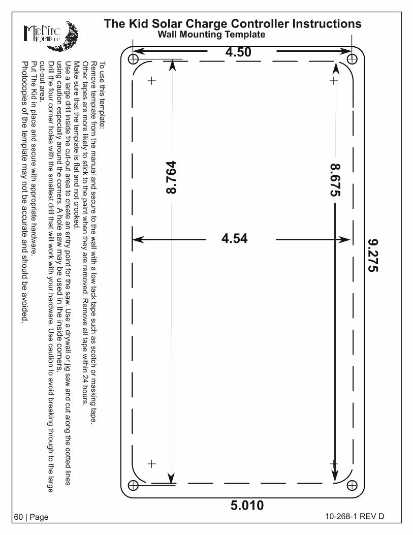
60 | Page
The Kid Solar Charge Controller Instructions
1 0-268-1 REV D
Wall Mounting Template
Tousethistemplate:
Removetemplatefromthemanualandsecuretothewallw
ithalowtacktapesuchassco
tchormaskin
gtape.
Othertapesaremorelike
lytostick
tothepaintwhentheyareremoved.Removeallta
pewithin24hours.
Makesurethatthetemplateisflatandnotcro
oked.
Usealargedrillin
sidethecut-outareatocre
ateanentry
pointforthesaw.Useadryw
allorjigsawandcutalongthedottedlines
usingcautionespeciallyaroundthecorners.A
holesawmaybeusedintheinsidecorners.
Drillth
efourcornerholeswiththesmallestdrillth
atwillw
orkwithyourhardware.Usecautiontoavoidbreakingthroughtothelarge
cut-outarea.
PutTheKidinplaceandsecurewithappropriatehardware.
Photocopiesofthetemplatemaynotbeaccu
rateandshouldbeavoided.
4.54
8.764
9.275
8.675
5.01 0
4.50