9600 compressor installation, operation, and maintenance ...9600 compressor installation, operation,...
TRANSCRIPT

ELIXH
©200
9600 Compressor Installation, Operation, and Maintenance Instructions
HELIX TECHNOLOGY CORPORATIONhttp://www.helixtechnology.com
4 Helix Technology Corporation Pub. No. 8040444, Rev. 101, 2/17/04 ECO No. 16163 Printed in USA

ELIXH
©200
The information in this document is believed to be accurate and reliable. However, Helix Technology Corporation, cannot accept any financial or other responsibilities that may result from the use of this information. No warranties are granted or extended by this document.
Helix Technology Corporation reserves the right to change any or all information contained herein without prior written notice. Revisions may be issued at the time of such changes and/or deletions.
Any duplication of this manual or any of its parts without expressed written permission from Helix Technology Corporation is strictly prohibited.
Any correspondence regarding this document should be forwarded to:
Helix Technology CorporationMansfield Corporate CenterNine Hampshire StreetMansfield, Massachusetts 02048-9171 U.S.A.
Telephone: (508) 337-5000FAX: (508) 337-5464
The following Helix Technology Corporation trademarks and service marks may appear in this document:
All other trademarks or registered trademarks are the property of their respective holders.
Conductron™ Convectron® Cryodyne® Cryogen®
Cryogenerator® Cryo-Torr® CTI-Cryogenics® FastRegen™
GOLDLink® Granville-Phillips™ GUTS® Helix Technology.. Your Vacuum ConnectionSM
Helix® Micro-Ion® Mini-Ion™ On-Board®
RetroEase® RetroFast® Stabil-1® Stabil-Ion®
ThinLine™ TurboPlus® Vacuum AssuranceSM
4 Helix Technology Corporation Printed in USA


9600 Compressor Installation, Operation, and Maintenance Instructions
©200
ELIXH
Table of ContentsFigures
Tables
Compressor Safety
Section 1 - 9600 Compressor DescriptionGeneral . . . . . . . . . . . . . . . . . . . . . . . . . . . . . . . . . . . . . . . . . . . . . . . . . . . . . . . . . . . 1-1Compressor Configurations . . . . . . . . . . . . . . . . . . . . . . . . . . . . . . . . . . . . . . . . . . . 1-1System Documentation . . . . . . . . . . . . . . . . . . . . . . . . . . . . . . . . . . . . . . . . . . . . . . 1-1CTI-CRYOGENICS Helium Refrigeration System . . . . . . . . . . . . . . . . . . . . . . . . 1-1Specifications . . . . . . . . . . . . . . . . . . . . . . . . . . . . . . . . . . . . . . . . . . . . . . . . . . . . . . 1-3
Dimensions . . . . . . . . . . . . . . . . . . . . . . . . . . . . . . . . . . . . . . . . . . . . . . . . . . . . 1-3Weight . . . . . . . . . . . . . . . . . . . . . . . . . . . . . . . . . . . . . . . . . . . . . . . . . . . . . . . . 1-5Electrical . . . . . . . . . . . . . . . . . . . . . . . . . . . . . . . . . . . . . . . . . . . . . . . . . . . . . . 1-5Cooling Water . . . . . . . . . . . . . . . . . . . . . . . . . . . . . . . . . . . . . . . . . . . . . . . . . . 1-6General . . . . . . . . . . . . . . . . . . . . . . . . . . . . . . . . . . . . . . . . . . . . . . . . . . . . . . . . 1-7
Component Description . . . . . . . . . . . . . . . . . . . . . . . . . . . . . . . . . . . . . . . . . . . . . . 1-7System Circuit Breaker . . . . . . . . . . . . . . . . . . . . . . . . . . . . . . . . . . . . . . . . . . . 1-9Elapsed Time Meter . . . . . . . . . . . . . . . . . . . . . . . . . . . . . . . . . . . . . . . . . . . . . . 1-9Control Circuit Breaker . . . . . . . . . . . . . . . . . . . . . . . . . . . . . . . . . . . . . . . . . . . 1-9Power ON Indicator . . . . . . . . . . . . . . . . . . . . . . . . . . . . . . . . . . . . . . . . . . . . . . 1-9Gas Charge Flared Fitting . . . . . . . . . . . . . . . . . . . . . . . . . . . . . . . . . . . . . . . . . 1-9Helium Pressure Gauge . . . . . . . . . . . . . . . . . . . . . . . . . . . . . . . . . . . . . . . . . . 1-10Power Inlet . . . . . . . . . . . . . . . . . . . . . . . . . . . . . . . . . . . . . . . . . . . . . . . . . . . . 1-10Return Gas Coupling . . . . . . . . . . . . . . . . . . . . . . . . . . . . . . . . . . . . . . . . . . . . 1-10Cooling Water IN . . . . . . . . . . . . . . . . . . . . . . . . . . . . . . . . . . . . . . . . . . . . . . . 1-10Cooling Water OUT . . . . . . . . . . . . . . . . . . . . . . . . . . . . . . . . . . . . . . . . . . . . . 1-10Cryopump Electrical Outlet . . . . . . . . . . . . . . . . . . . . . . . . . . . . . . . . . . . . . . . 1-10Compressor Remote Connector . . . . . . . . . . . . . . . . . . . . . . . . . . . . . . . . . . . . 1-11Supply Gas Coupling . . . . . . . . . . . . . . . . . . . . . . . . . . . . . . . . . . . . . . . . . . . . 1-11
Multiple On-Board Cryopump Connections . . . . . . . . . . . . . . . . . . . . . . . . . . . . . 1-12Multiple Cryo-Torr Cryopump Connections . . . . . . . . . . . . . . . . . . . . . . . . . . . . . 1-12
Section 2 - Unpacking and InspectionIntroduction . . . . . . . . . . . . . . . . . . . . . . . . . . . . . . . . . . . . . . . . . . . . . . . . . . . . . . . 2-1Shipping Carton Inspection . . . . . . . . . . . . . . . . . . . . . . . . . . . . . . . . . . . . . . . . . . . 2-1
4 Helix Technology Corporation Pub. No. 8040444, Rev. 101, 2/17/04 ECO No. 16163 v
9600 Compressor Installation, Operation, and Maintenance Instructions ELIXH
vi
Removal from Shipping Carton . . . . . . . . . . . . . . . . . . . . . . . . . . . . . . . . . . . . . . . . 2-1Compressor Inspection . . . . . . . . . . . . . . . . . . . . . . . . . . . . . . . . . . . . . . . . . . . . . . 2-2
Compressor . . . . . . . . . . . . . . . . . . . . . . . . . . . . . . . . . . . . . . . . . . . . . . . . . . . . 2-2Helium "OFF" Condition Pressure Verification . . . . . . . . . . . . . . . . . . . . . . . . 2-2Shipping Carton Contents . . . . . . . . . . . . . . . . . . . . . . . . . . . . . . . . . . . . . . . . . 2-2
Section 3 - InstallationIntroduction . . . . . . . . . . . . . . . . . . . . . . . . . . . . . . . . . . . . . . . . . . . . . . . . . . . . . . . 3-1Supply and Return Water Line Connections . . . . . . . . . . . . . . . . . . . . . . . . . . . . . . 3-3
Hard Water Lines . . . . . . . . . . . . . . . . . . . . . . . . . . . . . . . . . . . . . . . . . . . . . . . . 3-3Flexible Water Lines . . . . . . . . . . . . . . . . . . . . . . . . . . . . . . . . . . . . . . . . . . . . . 3-3
Electrical Connections . . . . . . . . . . . . . . . . . . . . . . . . . . . . . . . . . . . . . . . . . . . . . . . 3-4Power Cable Preparation . . . . . . . . . . . . . . . . . . . . . . . . . . . . . . . . . . . . . . . . . . 3-4Phase Check . . . . . . . . . . . . . . . . . . . . . . . . . . . . . . . . . . . . . . . . . . . . . . . . . . . . 3-6
. . . . . . . . . . . . . . . . . . . . . . . . . . . . . . . . . . . . . . . . . . . . . . . . . . . . . . . . . . . . . . . . . 3-6Connecting/Disconnecting Helium Flex Lines . . . . . . . . . . . . . . . . . . . . . . . . . . . . 3-7
Connecting . . . . . . . . . . . . . . . . . . . . . . . . . . . . . . . . . . . . . . . . . . . . . . . . . . . . . 3-7Disconnecting . . . . . . . . . . . . . . . . . . . . . . . . . . . . . . . . . . . . . . . . . . . . . . . . . . 3-7
Single On-Board Cryopump Connections . . . . . . . . . . . . . . . . . . . . . . . . . . . . . . . . 3-8Single Cryo-Torr Cryopump Connections . . . . . . . . . . . . . . . . . . . . . . . . . . . . . 3-9
Multiple On-Board Cryopump Connections . . . . . . . . . . . . . . . . . . . . . . . . . . . . . 3-11Helium Line Connections . . . . . . . . . . . . . . . . . . . . . . . . . . . . . . . . . . . . . . . . 3-11Power Cable Connections . . . . . . . . . . . . . . . . . . . . . . . . . . . . . . . . . . . . . . . . 3-11
Multiple Cryo-Torr Cryopump Connections . . . . . . . . . . . . . . . . . . . . . . . . . . . . . 3-14Helium Line Connections . . . . . . . . . . . . . . . . . . . . . . . . . . . . . . . . . . . . . . . . 3-14Power Cable Connections . . . . . . . . . . . . . . . . . . . . . . . . . . . . . . . . . . . . . . . . 3-14
Section 4 - OperationAdjusting System Helium Pressure . . . . . . . . . . . . . . . . . . . . . . . . . . . . . . . . . . . . . 4-1"OFF" Condition Helium System Pressure Verification . . . . . . . . . . . . . . . . . . . . . 4-1Compressor Operation . . . . . . . . . . . . . . . . . . . . . . . . . . . . . . . . . . . . . . . . . . . . . . . 4-2Replacement of Helium Circuit Components . . . . . . . . . . . . . . . . . . . . . . . . . . . . . 4-3
Section 5 - MaintenanceScheduled Maintenance . . . . . . . . . . . . . . . . . . . . . . . . . . . . . . . . . . . . . . . . . . . . . . 5-1
Suggested Maintenance Equipment . . . . . . . . . . . . . . . . . . . . . . . . . . . . . . . . . . 5-1Adsorber Replacement . . . . . . . . . . . . . . . . . . . . . . . . . . . . . . . . . . . . . . . . . . . . 5-2
Adjusting System Helium Pressure . . . . . . . . . . . . . . . . . . . . . . . . . . . . . . . . . . . . . 5-4Reducing Helium Pressure . . . . . . . . . . . . . . . . . . . . . . . . . . . . . . . . . . . . . . . . . 5-4Increasing Helium Pressure . . . . . . . . . . . . . . . . . . . . . . . . . . . . . . . . . . . . . . . . 5-5
Adding Helium . . . . . . . . . . . . . . . . . . . . . . . . . . . . . . . . . . . . . . . . . . . . . . . 5-5
©2004 Helix Technology Corporation Pub. No. 8040444, Rev. 101, 2/17/04 ECO No. 16163
9600 Compressor Installation, Operation, and Maintenance Instructions
©200
ELIXH
Appendix A - Customer Support InformationCustomer Support Center Locations . . . . . . . . . . . . . . . . . . . . . . . . . . . . . . . . . . . . A-1Guaranteed Up-Time Support (GUTS) . . . . . . . . . . . . . . . . . . . . . . . . . . . . . . . . . . A-1
Product Information . . . . . . . . . . . . . . . . . . . . . . . . . . . . . . . . . . . . . . . . . . . . . . A-1E-mail . . . . . . . . . . . . . . . . . . . . . . . . . . . . . . . . . . . . . . . . . . . . . . . . . . . . . . . . . . . . A-1
Appendix B - Flow Diagram
Appendix C - Troubleshooting ProceduresTroubleshooting the Compressor . . . . . . . . . . . . . . . . . . . . . . . . . . . . . . . . . . . . . . . C-1Technical Inquiries . . . . . . . . . . . . . . . . . . . . . . . . . . . . . . . . . . . . . . . . . . . . . . . . . C-1
Appendix D - SchematicIntroduction . . . . . . . . . . . . . . . . . . . . . . . . . . . . . . . . . . . . . . . . . . . . . . . . . . . . . . . D-1
Index
4 Helix Technology Corporation Pub. No. 8040444, Rev. 101, 2/17/04 ECO No. 16163 vii


ELIXH
©200.
Figures
Figure 1-1: 9600 Compressor . . . . . . . . . . . . . . . . . . . . . . . . . . . . . . . . . . . . . . 1-3Figure 1-2: 9600 Compressor Dimensions . . . . . . . . . . . . . . . . . . . . . . . . . . . . 1-4Figure 1-3: Water Flow Rate versus Pressure Drop . . . . . . . . . . . . . . . . . . . . . 1-6Figure 1-4: 9600 Compressor Rear View Component Locations. . . . . . . . . . . 1-8Figure 1-5: 9600 Compressor Connected to Multiple On-Board Cryopumps 1-12Figure 1-6: 9600 Compressor Connected to Multiple Cryo-Torr Cryopumps 1-13Figure 3-1:9600 Compressor Installation Flowchart . . . . . . . . . . . . . . . . . . . . 3-2Figure 3-2: 9600 Compressor Circuit Breaker Terminals (Cover Removed) . 3-5Figure 3-3: Connecting/Disconnecting Helium Flex Line Couplings . . . . . . . 3-8Figure 3-4: Single On-Board Cryopump Connections . . . . . . . . . . . . . . . . . . . 3-9Figure 3-5: Single Cryo-Torr Cryopump Installation. . . . . . . . . . . . . . . . . . . 3-10Figure 3-6: Recommended Multiple On-Board Cryopump or Waterpump Installation (Splitter Box located at Process Tool) . . . . . . . . . . . . . . . . . . . . . . . . . . . . . . 3-12Figure 3-7: Alternative Multiple On-Board Cryopump or Waterpump Installation (Splitter Box located at Compressor) . . . . . . . . . . . . . . . . . . . . . . . . . . . . . . . 3-13Figure 3-8: Multiple Cryo-Torr Cryopump Installation . . . . . . . . . . . . . . . . . 3-15Figure 3-9:Multiple Cryo-Torr Cryopump Installation . . . . . . . . . . . . . . . . . 3-16Figure 5-1: Disconnecting Self Sealing Couplings. . . . . . . . . . . . . . . . . . . . . . 5-2Figure 5-2: Adsorber Location, 9600 Compressor (Rear Panel Removed) . . . 5-3Figure 5-3: Helium Pressure Control Components. . . . . . . . . . . . . . . . . . . . . . 5-4Figure B-1:9600 Compressor Flow . . . . . . . . . . . . . . . . . . . . . . . . . . . . . . . . . B-2Figure D-1:9600 Compressor (Low Voltage) Schematic . . . . . . . . . . . . . . . . . D-5
4 Helix Technology Corporation Pub. No. 8040444, Rev. 101, 2/17/04 ECO No. 16163 ix


ELIXH
©200
Tables
Table 1-1:Compressor Weight . . . . . . . . . . . . . . . . . . . . . . . . . . . . . . . . . . 1-5Table 1-2:Electrical Input Specifications . . . . . . . . . . . . . . . . . . . . . . . . . . 1-5Table 1-3:Cooling Water Specifications. . . . . . . . . . . . . . . . . . . . . . . . . . . 1-6Table 1-4:General Compressor Operating Specifications . . . . . . . . . . . . . 1-7Table 1-5:Cryopump Electrical Outlet Pin Assignments . . . . . . . . . . . . . 1-11Table 1-6:Compressor Remote Connector Pin Assignments . . . . . . . . . . 1-11Table 4-1:9600 Compressor Helium ("OFF" Condition) Charge. . . . . . . . 4-1Table 5-1:Suggested Maintenance Equipment . . . . . . . . . . . . . . . . . . . . . . 5-1Table C-1:Compressor Troubleshooting Procedures . . . . . . . . . . . . . . . . . C-2Table D-2:Basic Control Assembly Legend. . . . . . . . . . . . . . . . . . . . . . . . D-1Table D-3:On-Board/Cryo Electrical Module P/N 8135127G001 Legend D-2Table D-4:On-Board Output Module P/N 8135148G001 Legend . . . . . . . D-3
4 Helix Technology Corporation Pub. No. 8040444, Rev. 101, 2/17/04 ECO No. 16163 xi


ELIXH
©200
Compressor Safety
CAUTIONSevere shock hazard. High voltage is present and electrical work should be per-formed by qualified personnel. All electrical work shall be performed in accor-dance with the National Electrical Code, ANSI/NFPA 70-1987, as well as all local codes.
Follow all local high voltage safety precautions to reduce the possibility of electrical shock. Make sure all electrical power is OFF before proceeding with this procedure.
Disconnecting means: the switch at the power entry module is set to the OFF position or the power cord shall be disconnected from the power entry module thereby disconnecting the Compressor from electrical power.
CAUTIONThe Compressor may start automatically when the remote start feature is used. Lockout and tagout the Compressor to prevent a remote start from occurring before attempting to service the Compressor.
CAUTIONThis is a general caution that describes various safety hazards or unsafe practices that could result in equipment damage.
4 Helix Technology Corporation S-1

ELIXH
S-2
WARNINGThis is a general warning that describes various safety hazards or unsafe practices that could result in personal injury or death.
CAUTIONBurn hazard. Allow the Compressor pump to cool before servicing the Compressor.
©2004 Helix Technology Corporation

9600 Compressor Installation, Operation, and Maintenance Instructions ELIXH
©200
Section 1 - 9600 Compressor Description
GeneralThis manual provides the information required to install, operate, and maintain the CTI-CRYOGENICS 9600 Compressor.
NOTE: All personnel with installation, operation, and maintenance responsibilities should become familiar with the contents of both the 9600 Compressor Installation, Operation, Maintenance, and appropriate cryopump manuals to ensure safe, high quality, and reliable system performance.
Compressor ConfigurationsThe 9600 Compressor supports either On-Board or Cryo-Torr Cryopumps. For multiple cryopump installations, an On-Board Splitter Box or Cryo-Torr Interface can be used for cold head power distribution that reduces total cable requirements as shown in Figure 1-5 and Figure 1-6.
System DocumentationThe manuals for a system cover two basic components: the cryopump and the Compressor. A manual is shipped with each system component to
provide information for installation and operation of that component. A loose-leaf binder with index tab separators is also provided so you can compile a complete set of tabulated manuals.
CTI-CRYOGENICS Helium Refrigeration SystemThe operation of CTI-CRYOGENICS’ cryopumps is based upon a closed loop helium expansion cycle. The system is made up of two major
CAUTIONRefer to “Appendix A - Customer Support Information” to contact the local Customer Support Center for information on connecting 9600 Compressors to a manifold with other CTI-CRYOGENICS compressors.
4 Helix Technology Corporation Pub. No. 8040444, Rev. 101, 2/17/04 ECO No. 16163 1-1

CTI-CRYOGENICS Helium Refrigeration System ELIXH
1-2
components: the cryopump, which contains the cold head, and the helium Compressor which compresses the helium gas.
Refrigeration is produced in the cryopump cold head through periodic expansion of high pressure helium in a regenerative process. The high pressure helium is provided by the Compressor. Low pressure helium returning from the cold head is compressed into the necessary high pressure to be returned to the cold head. The energy required to compress the helium is rejected as heat through the cooling water.
High pressure room temperature helium is transferred to the cold head through the supply lines. After expansion, low pressure helium is returned to the Compressor (at or near room temperature) to repeat the cycle in a closed loop fashion. Large separation distances can be accommodated between the Compressor and the cryopump.
In the Compressor, helium is compressed using a highly reliable oil lubricated commercial Compressor. Helium purification takes place via several stages of oil removal. The final stage of purification is performed with a replaceable adsorber cartridge. In order to maintain peak efficiency, the adsorber must be replaced every three years. The 9600 Compressor is shown in Figure 1-1.
©2004 Helix Technology Corporation Pub. No. 8040444, Rev. 101, 2/17/04 ECO No. 16163

9600 Compressor Installation, Operation, and Maintenance Instructions ELIXH
©200
Figure 1-1: 9600 Compressor
Specifications
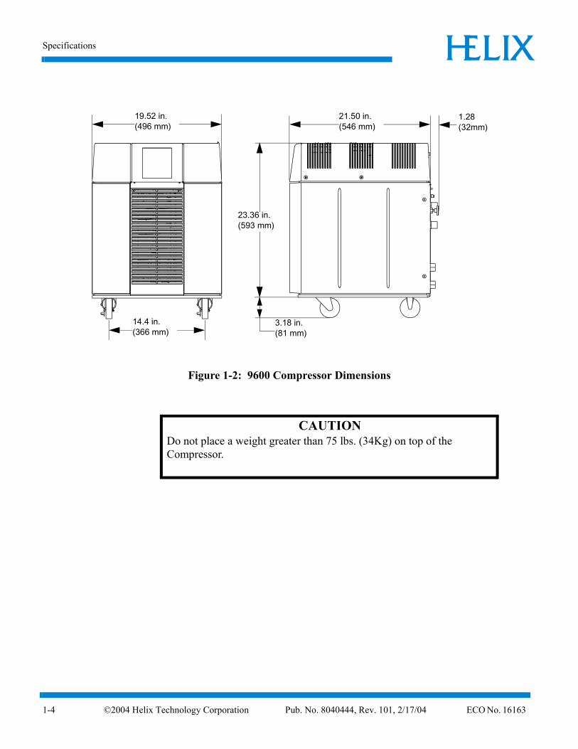
Dimensions
The dimensions of the Compressor are shown in Figure 1-2.
9600
COMPRESSORCOMPRESSOR9600
4 Helix Technology Corporation Pub. No. 8040444, Rev. 101, 2/17/04 ECO No. 16163 1-3
Specifications ELIXH
1-4
Figure 1-2: 9600 Compressor Dimensions
19.52 in.(496 mm)
21.50 in.(546 mm)
1.28(32mm)
23.36 in.(593 mm)
3.18 in.(81 mm)
14.4 in.(366 mm)
CAUTIONDo not place a weight greater than 75 lbs. (34Kg) on top of the Compressor.
©2004 Helix Technology Corporation Pub. No. 8040444, Rev. 101, 2/17/04 ECO No. 16163
9600 Compressor Installation, Operation, and Maintenance Instructions ELIXH
©200
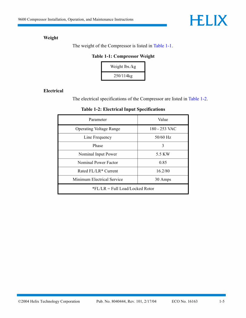
Weight
The weight of the Compressor is listed in Table 1-1.
Electrical
The electrical specifications of the Compressor are listed in Table 1-2.
Table 1-1: Compressor Weight
Weight lbs./kg
250/114kg
Table 1-2: Electrical Input Specifications
Parameter Value
Operating Voltage Range 180 - 253 VAC
Line Frequency 50/60 Hz
Phase 3
Nominal Input Power 5.5 KW
Nominal Power Factor 0.85
Rated FL/LR* Current 16.2/80
Minimum Electrical Service 30 Amps
*FL/LR = Full Load/Locked Rotor
4 Helix Technology Corporation Pub. No. 8040444, Rev. 101, 2/17/04 ECO No. 16163 1-5

Specifications ELIXH
1-6
Cooling Water
The water used to cool the Compressor must meet the specifications shown in Table 1-3 for proper system operation.
Figure 1-3: Water Flow Rate versus Pressure Drop
Table 1-3: Cooling Water Specifications
Parameter Value
Maximum Inlet Temperature 90°F (32°C)
Minimum Inlet Temperature 50°F (10°C)
Flow Rate 2.75 ±1.25 gpm (10.4 ± 4.7 lpm)
Pressure Drop (inlet-to-outlet) See Figure 1-3
Maximum Inlet Pressure 100 psi (6.9 bars)
Alkalinity 6.0 - 8.0 pH
Calcium Carbonate < 75 ppm
NOTE: Water conditioning may be required for applications not meeting these requirements.
4.00
3.50
3.00
2.50
2.00
1.50
1.00
0.501 3 5 7 9 11
WAT
ER
FLO
W R
ATE
(G
PM
)
WATER PRESSURE DROP (PSID)
ACCEPTABLE
OPERATING
LINE
.07 .49.21 .35 .63 .7715.2
13.3
11.40
9.50
7.60
5.70
3.80
1.90
WAT
ER
FLO
W R
ATE
(LP
M)
WATER PRESSURE DROP (Bars)
NOTE: Figure 1-3 defines the water flow rate through the Compressor as a function of the pressure drop from water inlet to water outlet. You must provide the correct pressure drop in your water supply system to ensure that the water flow condition meets the requirements specified in Table 1-3.
©2004 Helix Technology Corporation Pub. No. 8040444, Rev. 101, 2/17/04 ECO No. 16163

9600 Compressor Installation, Operation, and Maintenance Instructions ELIXH
©200
General
The information in Table 1-4 provides general Compressor operating specifications.
NOTE: The 9600 Compressor is designed for continuous operation and should remain ON when the cryopumps are in a regeneration cycle.
Component DescriptionThe components of the 9600 Compressor that are accessible from the rear panel are shown in Figure 1-4 and described in the following paragraphs.
Table 1-4: General Compressor Operating Specifications
Specification Values
Part Numbers 8135900G001 8135908G001
Input Power Cable(Customer Supplied)
600 VAC10 Gauge, 3 conductor wire with groundMust conform to local electrical codes
Nominal Helium Pressure Refer to Table 4-1
Ambient Operating Tem-perature Range
50 - 100º F (10 - 38º C)
Interface
Gas Supply Connector
Gas Return Connector
Remote Control Receptacle
Cryopump Power Receptacles: mates with the CTI-CRYOGENICS supplied cryopump power cable for single pump use.
Mates with remote junction box power cable for multiple cry-opump use.
1/2 in. Aeroquip self-sealing coupling
1/2 in. Aeroquip self-sealing coupling
24VAC, 2.7A inductive mates with P5 connector P/N MS3106A*
Adsorber Service Schedule 3 Years
* Supplied by CTI-CRYOGENICS
4 Helix Technology Corporation Pub. No. 8040444, Rev. 101, 2/17/04 ECO No. 16163 1-7

Component Description ELIXH
1-8
Figure 1-4: 9600 Compressor Rear View Component Locations
Control Circuit Breaker
System Circuit Breaker
Power Inlet
Gas Charge Flared Fitting
Helium Pressure Gauge
Cryopump Electrical Outlet
Supply GasCoupling
Return Gas Coupling
Cooling Water OUT
Compressor RemoteConnector
Rear Panel
Gas Charge Control Valve
Cooling Water IN
Elapsed Time Meter
Power ON Indicator
©2004 Helix Technology Corporation Pub. No. 8040444, Rev. 101, 2/17/04 ECO No. 16163
9600 Compressor Installation, Operation, and Maintenance Instructions ELIXH
©200
System Circuit Breaker
The System Circuit Breaker protects main input power to the Compressor pump and module. The circuit breaker positions are labeled ON (1), which is in the UP position, and OFF (0), which is in the DOWN position.
NOTE: The phase monitor in the Compressor will cause the system circuit breaker to open when input power phases are incorrect.
Elapsed Time Meter
The Elapsed Time Meter records the number of Compressor operating hours. Since the meter is digital, it is not illuminated unless the system circuit breaker is in the ON position and power is connected to the Compressor. The Elapsed Time Meter maintains the correct accumulated operating hours while system power is turned OFF.
NOTE: The meter cannot be reset.
Control Circuit Breaker
The Control Circuit Breaker provides current overload protection for all internal components of the Compressor except the Compressor motor. The Compressor motor is protected by a separate overload protector. The Control Circuit Breaker opens automatically and must be reset manually.
Power ON Indicator
The Power On Indicator illuminates when the system circuit breaker is placed in the ON position. The Compressor pump is energized when the power indicator is illuminated and the elapsed time meter records system
operation time.
Gas Charge Flared Fitting
The Gas Charge Flared Fitting is used to connect a 99.999% pure helium supply to the Compressor when helium charging is required. The fitting has a 45º flare and 7/16 in. x 20 threads/inch.
Refer to “Section 5 - Maintenance” for information on adding helium to the Compressor.
4 Helix Technology Corporation Pub. No. 8040444, Rev. 101, 2/17/04 ECO No. 16163 1-9

Component Description ELIXH
1-10
Helium Pressure Gauge
The Helium Pressure Gauge indicates system ("OFF" Condition) helium charge pressure when the Compressor and cryopumps are OFF and Compressor suction or inlet pressure when the Compressor is ON. Refer to Table 4-1 for the appropriate ("OFF" Condition) helium charge pressure.
Power Inlet
The Power Inlet is used to connect your power cable to the Compressor. Refer to “Section 3 - Installation” for information on power cable installation.
Return Gas Coupling
The Return Gas Coupling returns the helium, which has been cycled through the cryopump, back to the Compressor. Refer to “CTI-CRYOGENICS Helium Refrigeration System” in this section for more information.
Cooling Water IN
The Cooling Water IN connector provides water to the Compressor from your facility to cool the Compressor during operation. The connector thread size is a 1/2 in. female pipe thread. The water must meet the specifications outlined in Table 1-3. Refer to “Section 3 - Installation” for more information on cooling water connections.
Cooling Water OUT
The Cooling Water OUT connector returns the water that has been used to cool the Compressor to your facility. The connector thread size is a 1/2 in. female pipe thread. Refer to “Section 3 - Installation” for more information on cooling water connections.
Cryopump Electrical Outlet
The Cryopump Electrical Outlet provides power to a single On-Board or Cryo-Torr Cryopump, an On-Board Splitter Box, or a Cryo-Torr Interface. The Compressor requires the use of an On-Board Splitter Box or
©2004 Helix Technology Corporation Pub. No. 8040444, Rev. 101, 2/17/04 ECO No. 16163

9600 Compressor Installation, Operation, and Maintenance Instructions ELIXH
©200
Cryo-Torr Interface for multiple cryopump system connections. Refer to Table 1-5 for connector pin identification. Refer to “Multiple On-Board Cryopump Connections” or “Multiple Cryo-Torr Cryopump Connections” in this section for more information.
Compressor Remote Connector
The Compressor Remote Connector is a two-pin connector that can be used in conjunction with the On-Board setpoint relays, relays in the Cryo-Torr Interface, or a signal from the vacuum system to turn the Compressor ON or OFF. Refer to Table 1-6 for connector pin identification. Switching contacts must be rated at 24VDC, 2.7A inductive.
NOTE: The Compressor is shipped with a mating plug which must remain installed in the Compressor Remote Connector to ensure Compressor operation when the Compressor remote feature is not being used.
Supply Gas Coupling
The Supply Gas Coupling provides a connection for high pressure compressed helium to the cryopump cold head. Refer to “CTI-CRYOGENICS Helium Refrigeration System” in this section for more information.
Table 1-5: Cryopump Electrical Outlet Pin Assignments
Identifier Function
A and B Heater Power - 208 VAC nominal
C Center tap for D and E
D and E 24 VCT @ 4.6 Amps
F-G and G-H Cold Head Voltage Output 130-160 VAC @ 4.5 Amps
J Chassis Ground
K Not Used
Table 1-6: Compressor Remote Connector Pin Assignments
Identifier Function
A and B Compressor Remote Control - Make = ON, Break = OFF
4 Helix Technology Corporation Pub. No. 8040444, Rev. 101, 2/17/04 ECO No. 16163 1-11
Multiple On-Board Cryopump Connections ELIXH
1-12
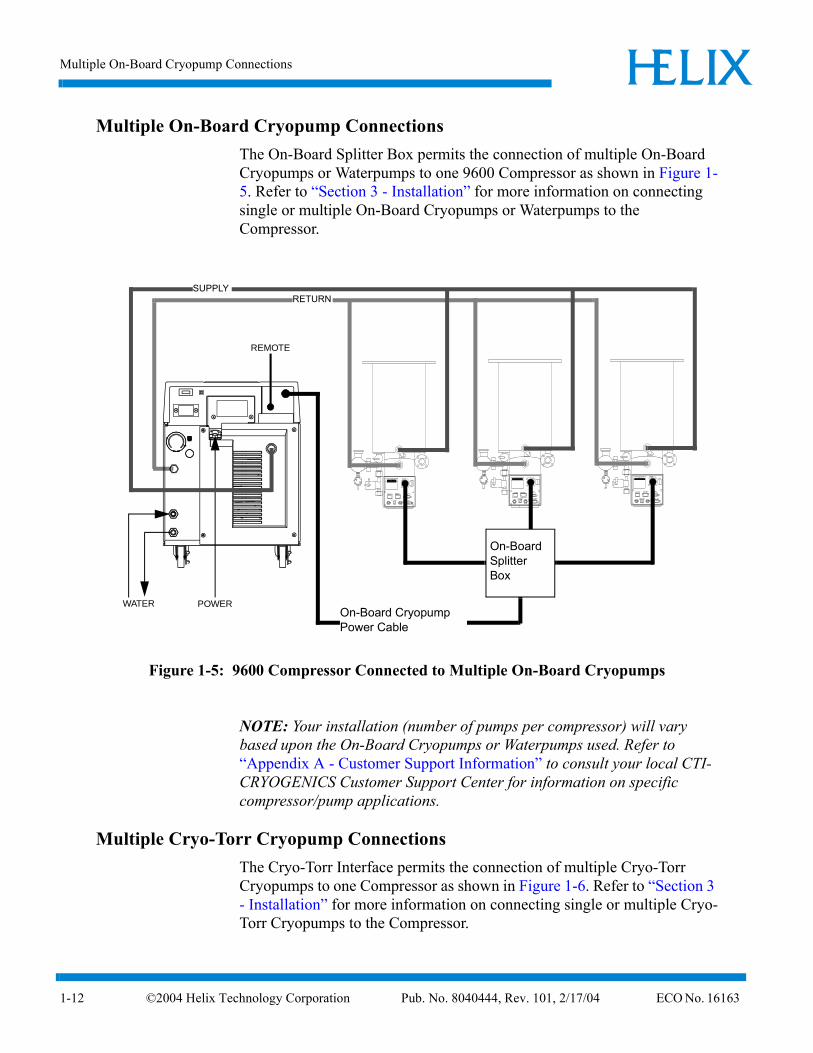
Multiple On-Board Cryopump ConnectionsThe On-Board Splitter Box permits the connection of multiple On-Board Cryopumps or Waterpumps to one 9600 Compressor as shown in Figure 1-5. Refer to “Section 3 - Installation” for more information on connecting single or multiple On-Board Cryopumps or Waterpumps to the Compressor.
Figure 1-5: 9600 Compressor Connected to Multiple On-Board Cryopumps
NOTE: Your installation (number of pumps per compressor) will vary based upon the On-Board Cryopumps or Waterpumps used. Refer to “Appendix A - Customer Support Information” to consult your local CTI-CRYOGENICS Customer Support Center for information on specific compressor/pump applications.
Multiple Cryo-Torr Cryopump ConnectionsThe Cryo-Torr Interface permits the connection of multiple Cryo-Torr Cryopumps to one Compressor as shown in Figure 1-6. Refer to “Section 3 - Installation” for more information on connecting single or multiple Cryo-Torr Cryopumps to the Compressor.
SUPPLYRETURN
WATER POWEROn-Board Cryopump Power Cable
On-BoardSplitter Box
REMOTE
©2004 Helix Technology Corporation Pub. No. 8040444, Rev. 101, 2/17/04 ECO No. 16163

9600 Compressor Installation, Operation, and Maintenance Instructions ELIXH
©200
Figure 1-6: 9600 Compressor Connected to Multiple Cryo-Torr Cryopumps
NOTE: Your installation (number of pumps per compressor) will vary based upon the Cryo-Torr Cryopump models used. Refer to “Appendix A - Customer Support Information”to consult your local CTI-CRYOGENICS Customer Support Center for information on specific compressor/cryopump applications.
Cryopump Electrical InputUser Remote(from vacuum system)
SUPPLY
RETURN
WATER POWER
Cryo-Torr Interface
Remote
4 Helix Technology Corporation Pub. No. 8040444, Rev. 101, 2/17/04 ECO No. 16163 1-13

9600 Compressor Installation, Operation, and Maintenance Instructions ELIXH
©200
Section 2 - Unpacking and Inspection
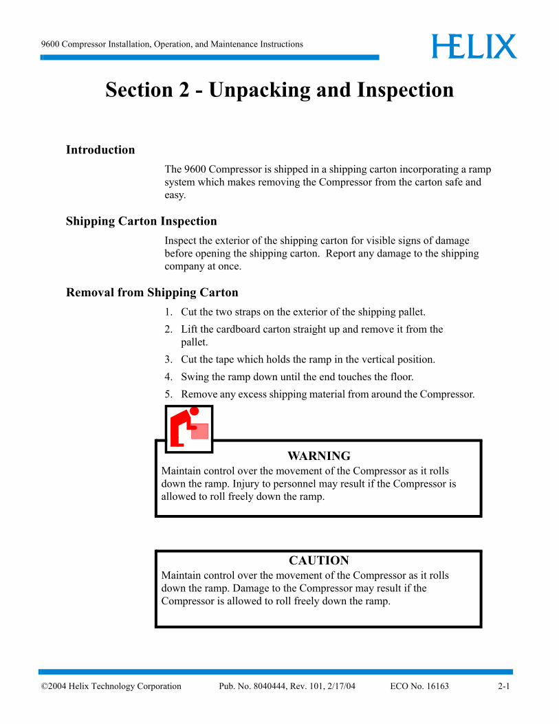
IntroductionThe 9600 Compressor is shipped in a shipping carton incorporating a ramp system which makes removing the Compressor from the carton safe and easy.
Shipping Carton InspectionInspect the exterior of the shipping carton for visible signs of damage before opening the shipping carton. Report any damage to the shipping company at once.
Removal from Shipping Carton1. Cut the two straps on the exterior of the shipping pallet.2. Lift the cardboard carton straight up and remove it from the
pallet.3. Cut the tape which holds the ramp in the vertical position.4. Swing the ramp down until the end touches the floor.5. Remove any excess shipping material from around the Compressor.
WARNINGMaintain control over the movement of the Compressor as it rolls down the ramp. Injury to personnel may result if the Compressor is allowed to roll freely down the ramp.
CAUTIONMaintain control over the movement of the Compressor as it rolls down the ramp. Damage to the Compressor may result if the Compressor is allowed to roll freely down the ramp.
4 Helix Technology Corporation Pub. No. 8040444, Rev. 101, 2/17/04 ECO No. 16163 2-1

Compressor Inspection ELIXH
2-2
6. Carefully roll the Compressor down the ramp and onto the floor.
Compressor InspectionInspect the Compressor for visible signs of damage as indicated in the following paragraphs.
Compressor
Inspect the exterior of the Compressor for visible signs of damage, evidence of an oil leak, and check the Helium Pressure Gauge for proper helium pressure. Report any damage to the shipping company at once.
Helium "OFF" Condition Pressure Verification
Refer to “Section 4 - Operation” for more information on the "OFF" Condition helium charge pressure of the 9600 Compressor.
Shipping Carton Contents
The shipping carton should contain the following items:
• Compressor
• Two barbed fittings for flexible water lines
• Installation, Operation, and Maintenance manual
• Compressor remote start connector and strain relief
©2004 Helix Technology Corporation Pub. No. 8040444, Rev. 101, 2/17/04 ECO No. 16163
9600 Compressor Installation, Operation, and Maintenance Instructions ELIXH
©200
Section 3 - Installation
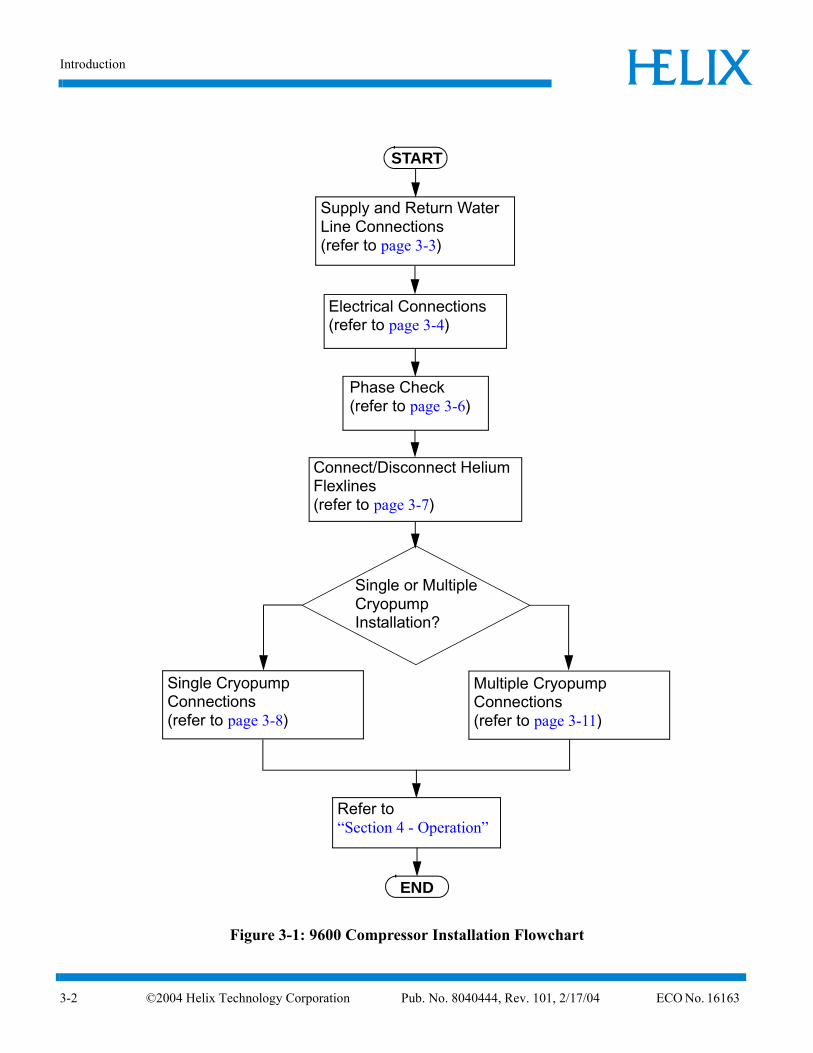
IntroductionSection 3 provides you with the information required to install the 9600 Compressor and connect it to single or multiple On-Board or Cryo-Torr Cryopump configurations. Figure 3-1 highlights the major tasks for Compressor installation and refers to the appropriate installation procedures in this section.
4 Helix Technology Corporation Pub. No. 8040444, Rev. 101, 2/17/04 ECO No. 16163 3-1
Introduction ELIXH
3-2
Figure 3-1: 9600 Compressor Installation Flowchart
Supply and Return WaterLine Connections(refer to page 3-3)
Electrical Connections(refer to page 3-4)
Phase Check(refer to page 3-6)
Single Cryopump Connections(refer to page 3-8)
START
Refer to “Section 4 - Operation”
END
Single or MultipleCryopumpInstallation?
Multiple Cryopump Connections(refer to page 3-11)
Connect/Disconnect Helium Flexlines(refer to page 3-7)
©2004 Helix Technology Corporation Pub. No. 8040444, Rev. 101, 2/17/04 ECO No. 16163
9600 Compressor Installation, Operation, and Maintenance Instructions ELIXH
©200
Supply and Return Water Line ConnectionsNOTE: The water used for cooling the Compressor must meet the specifications outlined in “Section 1 - 9600 Compressor Description”.
Hard Water Lines
1. Apply a light coating of standard plumbing thread sealant to the hard line pipe threads.
2. Install the Supply hard line into the INPUT connection on the rear panel of the Compressor. Tighten the fitting by hand.
3. Install the Return hard line into the OUTPUT connection on the rear panel of the Compressor. Tighten the fitting by hand.
4. Using a wrench, tighten the fittings.5. Allow water to flow and check for leaks at the rear of the
Compressor.
Flexible Water Lines
1. Apply a light coating of standard plumbing thread sealant to the barbed fitting threads.
2. Install the barbed fittings into the INPUT and OUTPUT connections on the rear panel of the Compressor.
3. Using a wrench, tighten the barbed fittings.4. Connect the Supply flexible water line to the INPUT barbed fitting
and secure with a hose clamp.5. Connect the Return flexible water line to the OUTPUT barbed
fitting and secure with a hose clamp.
CAUTIONDo not overtighten the ferrules. Damage to the input and output connector threads may occur.
CAUTIONDo not overtighten the barbed fittings. Damage to the INPUT and OUTPUT connector threads may occur.
4 Helix Technology Corporation Pub. No. 8040444, Rev. 101, 2/17/04 ECO No. 16163 3-3

Electrical Connections ELIXH
3-4
6. Allow water to flow and check for leaks at the rear of the Compressor.
Electrical ConnectionsThe following procedures provide information for making all three phase (180 - 250 VAC) electrical connections to the Compressor.
Power Cable Preparation
1. Cut a 10 AWG (6.00 mm2), 3 conductor cable with ground to an appropriate length.
2. Strip the cable jacket back 4 in. (101.6 mm).3. Strip the insulation back 3/8 in. (9.3 mm) on each individual
conductor.4. Install a #10 ring tongue terminal on the end of each conductor
using the appropriate size double crimping tool.5. Remove the rear panel as shown in Figure 3-2.6. Remove the circuit breaker terminal cover as shown in Figure 3-2.7. Install the cable into the Compressor through the cable strain relief.8. Remove the 10-32 nut and install the grounding wire on the ground
stud. Install the nut and tighten to 18 in.-lbs (0.21m-kg).
WARNINGFollow all local high voltage safety precautions when performing this procedure to reduce the possibility of electrical shock. Make sure all electrical power is OFF before proceeding with this procedure.
CAUTIONThe cable used for making the Compressor power cable must be 10 gauge, 3 conductor cable with ground rated at 600 VAC.
©2004 Helix Technology Corporation Pub. No. 8040444, Rev. 101, 2/17/04 ECO No. 16163

9600 Compressor Installation, Operation, and Maintenance Instructions ELIXH
©200
NOTE: Use a slotted screwdriver which is capable of holding a screw when performing steps 9 and 10.
9. Remove the screws from the Compressor circuit breaker terminals X, Y, and Z as shown in Figure 3-2.
Figure 3-2: 9600 Compressor Circuit Breaker Terminals (Cover Removed)
NOTE: The phase order in which the conductor terminal lugs are connected to circuit breaker terminals X, Y, and Z will be determined during the Phase Check Procedure.
NOTE: For installation where one of the three phase legs is at or near ground potential, connect that leg to terminal Y on the Compressor as shown in Figure 3-2.
10. Install the conductor terminal lugs to the circuit breaker terminals X, Y, and Z as shown in Figure 3-2.
11. Torque the screws to 12 in.-lbs (0.14m-kg).12. Allow enough cable to stay in the electrical enclosure to prevent
strain on the electrical connections and tighten the screws on the cable strain relief.
13. Install the power source end of the power cable according to the local electrical codes.
14. Install the circuit breaker terminal cover.15. Proceed with Phase Check.
X Y Z
Detail A
See Detail A
Three Phase PowerRear Panel
Circuit Breaker Terminal Cover
4 Helix Technology Corporation Pub. No. 8040444, Rev. 101, 2/17/04 ECO No. 16163 3-5

ELIXH
3-6
Phase Check
1. Make sure power is applied to compressor circuit as described in Table 1-2.
NOTE: The circuit breaker will trip immediately during step 2 if the power phase connections are not correct.
2. Turn the Compressor circuit breaker to the ON position. If the circuit breaker trips, refer to step 3. If the circuit breaker does not trip, refer to step 4.
3. If the circuit breaker trips, perform the following steps:a. Turn the Compressor circuit breaker to the OFF position.b. Disconnect the power cord from the power source.c. Remove the circuit breaker terminal cover.d. Reverse the wiring order of Compressor circuit breaker
terminals X and Y.e. Torque the circuit breaker terminal screws to 12 in.-lbs.f. Install the circuit breaker terminal cover.g. Repeat steps 1- 2 of this procedure.
4. Install the rear panel.5. Proceed with appropriate cryopump connections.
WARNINGFollow all high voltage safety precautions when performing this procedure to prevent the possibility of electrical shock.
©2004 Helix Technology Corporation Pub. No. 8040444, Rev. 101, 2/17/04 ECO No. 16163

9600 Compressor Installation, Operation, and Maintenance Instructions ELIXH
©200
Connecting/Disconnecting Helium Flex Lines
Connecting
1. Remove all dust plugs and caps from the Gas Supply and Return lines, and the Compressor and cryopump Supply and Return connectors. Check for the presence of a flat gasket in the male connector, and no gasket in the female connector.
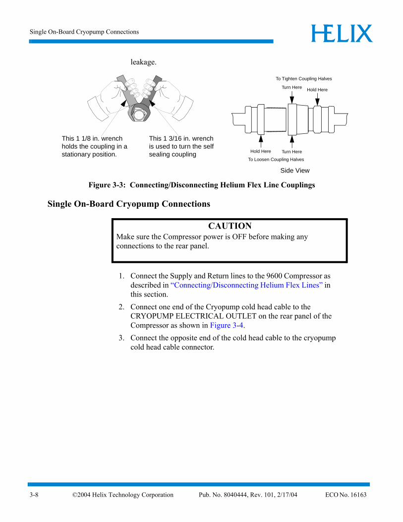
2. Connect the Gas Return line to the GAS RETURN connector on the rear of the Compressor and then to the GAS RETURN connector on the cryopump. Using two wrenches as shown in Figure 3-3, tighten the connector.
3. Connect the Gas Supply line to the GAS SUPPLY connector on the rear of the Compressor and then to the GAS SUPPLY connector on the cryopump. Using two wrenches as shown in Figure 3-3, tighten the connector.
4. Attach the Supply and Return line identification labels to each end of the appropriate lines.
Disconnecting
1. Using two wrenches as shown in Figure 3-3, disconnect the two self sealing coupling connectors quickly to minimize helium
CAUTIONMake sure the helium flex lines are connected and disconnected from the 9600 Compressor using the following procedure and as shown in Figure 3-3. Failure to follow this procedure could damage connector O-ring seals or cause a helium circuit leak.
4 Helix Technology Corporation Pub. No. 8040444, Rev. 101, 2/17/04 ECO No. 16163 3-7
Single On-Board Cryopump Connections ELIXH
3-8
leakage.
Figure 3-3: Connecting/Disconnecting Helium Flex Line Couplings
Single On-Board Cryopump Connections
1. Connect the Supply and Return lines to the 9600 Compressor as described in “Connecting/Disconnecting Helium Flex Lines” in this section.
2. Connect one end of the Cryopump cold head cable to the CRYOPUMP ELECTRICAL OUTLET on the rear panel of the Compressor as shown in Figure 3-4.
3. Connect the opposite end of the cold head cable to the cryopump cold head cable connector.
This 1 3/16 in. wrench is used to turn the self sealing coupling
This 1 1/8 in. wrench holds the coupling in a stationary position.
Side View
To Tighten Coupling Halves
Hold HereTurn Here
Hold Here Turn Here
To Loosen Coupling Halves
CAUTIONMake sure the Compressor power is OFF before making any connections to the rear panel.
©2004 Helix Technology Corporation Pub. No. 8040444, Rev. 101, 2/17/04 ECO No. 16163

9600 Compressor Installation, Operation, and Maintenance Instructions ELIXH
©200
.
Figure 3-4: Single On-Board Cryopump Connections
Single Cryo-Torr Cryopump Connections
1. Connect the Supply and Return lines to the 9600 Compressor as described in “Connecting/Disconnecting Helium Flex Lines” in this section.
2. Connect one end of the Cryopump cold head cable to the CRYOPUMP ELECTRICAL OUTLET on the rear panel of the Compressor as shown in Figure 3-5. Connect the opposite end of the cold head cable to the cryopump cold head cable connector as shown in Figure 3-5.
On-Board Cryopump Power Cable
WATER POWER
REMOTE
SUPPLY
RETURN
CAUTIONMake sure the Compressor power is OFF before making any connections to the rear panel.
4 Helix Technology Corporation Pub. No. 8040444, Rev. 101, 2/17/04 ECO No. 16163 3-9

Single On-Board Cryopump Connections ELIXH
3-10
Figure 3-5: Single Cryo-Torr Cryopump Installation
Cryo-Torr Power Cable
SUPPLY
RETURN
WATER POWER
REMOTE
©2004 Helix Technology Corporation Pub. No. 8040444, Rev. 101, 2/17/04 ECO No. 16163

9600 Compressor Installation, Operation, and Maintenance Instructions ELIXH
©200
Multiple On-Board Cryopump Connections
Helium Line Connections
1. Connect the Supply and Return lines to the 9600 Compressor as described in “Connecting/Disconnecting Helium Flex Lines” in this section.
2. Connect the Gas Return Line to the customer supplied helium manifold and then to the GAS RETURN connector on the On-Board Cryopump.
3. Connect the Gas Supply Line to the customer supplied helium manifold and then to the GAS SUPPLY connector on the On-Board Cryopump.
Power Cable Connections
1. Connect the On-Board Splitter Box power cable between the CRYOPUMP ELECTRICAL OUTLET on the rear panel of the Compressor and the On-Board Splitter Box power connector as shown in Figure 3-6.
2. Connect the On-Board Cryopump or Waterpump power cables to the CRYOPUMP 1, 2, or 3 connectors on the On-Board Splitter Box and the respective cryopumps as shown in Figure 3-6.
CAUTIONMake sure the Compressor power is OFF before making any connections to the rear panel.
CAUTIONThe use of several compressors on a single manifold feeding a common supply header and a common return header requires special precautions. Contact CTI-CRYOGENICS for a review of the intended installation and for specific technical instructions. The use of a 9600 compressor on a manifold with other CTI-CRYOGENICS compressor models requires a reduction of the helium charge pressure to 200 - 210 psig charge pressure to avoid helium safety valves from inadvertently venting. Refer to “Section 4 - Operation” and “Section 5 - Maintenance” for more information.
4 Helix Technology Corporation Pub. No. 8040444, Rev. 101, 2/17/04 ECO No. 16163 3-11

Multiple On-Board Cryopump Connections ELIXH
3-12
NOTE: Your installation (number of pumps per compressor) will vary based upon the On-Board Cryopump models used. Refer to “Appendix A - Customer Support Information” to consult your local CTI-CRYOGENICS Customer Support Center for information on specific compressor/pump applications.
NOTE: The On-Board Splitter Box can be installed at the process tool containing the pumps as shown in Figure 3-6, or on the rear of the Compressor as shown in Figure 3-7. CTI-CRYOGENICS recommends that the On-Board Splitter box be installed near the process tool to reduce cable requirements.
Figure 3-6: Recommended Multiple On-Board Cryopump or Waterpump Installation (Splitter Box located at Process Tool)
SUPPLYRETURN
WATER POWER
On-Board Power Cable
REMOTE
On-Board Splitter Box
©2004 Helix Technology Corporation Pub. No. 8040444, Rev. 101, 2/17/04 ECO No. 16163

9600 Compressor Installation, Operation, and Maintenance Instructions ELIXH
©200
Figure 3-7: Alternative Multiple On-Board Cryopump or Waterpump Installation (Splitter Box located at Compressor)
SUPPLYRETURN
WATER POWER
REMOTE
On-Board Power Cables
On-Board Splitter Box
4 Helix Technology Corporation Pub. No. 8040444, Rev. 101, 2/17/04 ECO No. 16163 3-13

Multiple Cryo-Torr Cryopump Connections ELIXH
3-14
Multiple Cryo-Torr Cryopump Connections
Helium Line Connections
1. Connect the Supply and Return lines to the 9600 Compressor as described in “Connecting/Disconnecting Helium Flex Lines” in this section.
2. Connect the Gas Return Line to the customer supplied helium manifold and then to the Gas Return connector on the Cryo-Torr Cryopump.
3. Connect the Gas Supply Line to the customer supplied helium manifold and then to the Gas Supply connector on the Cryo-Torr Cryopump.
Power Cable Connections
1. Connect the Cryo-Torr power cable between the CRYOPUMP ELECTRICAL OUTLET on the rear panel of the Compressor and the CRYOPUMP ELECTRICAL INPUT on the Cryo-Torr Interface as shown in Figure 3-8 or Figure 3-9.
CAUTIONMake sure the Compressor power is OFF before making any connections to the rear panel.
CAUTIONThe use of several compressors on a single manifold feeding a common supply header and a common return header requires special precautions. Contact CTI-CRYOGENICS for a review of the intended installation and for specific technical instructions.
The use of a 9600 compressor on a manifold with other CTI-CRYOGENICS compressor models requires a reduction of the helium charge pressure to 200 - 210 psig charge pressure to avoid helium safety valves from inadvertently venting. Refer to “Section 4 - Operation” and “Section 5 - Maintenance” for more information.
©2004 Helix Technology Corporation Pub. No. 8040444, Rev. 101, 2/17/04 ECO No. 16163

9600 Compressor Installation, Operation, and Maintenance Instructions ELIXH
©200
2. Connect the Cryo-Torr Power Cables between the CRYOPUMP 1, 2, or 3 connectors on the Cryo-Torr Interface and the respective Cryo-Torr Cryopumps as shown in Figure 3-8 or Figure 3-9.
3. Connect the User Remote cable to the Cryo-Torr Interface as shown in Figure 3-8 or Figure 3-9.
4. Connect the Remote cable between the Cryo-Torr Interface and the Compressor as shown in Figure 3-8 or Figure 3-9.
NOTE: Your installation may vary based upon the Cryo-Torr Cryopump models used. Refer to “Appendix A - Customer Support Information” to consult your local CTI-CRYOGENICS Customer Support Center for information on specific compressor/cryopump applications.
NOTE: The Cryo-Torr Interface can be installed at the process tool containing the cryopumps as shown in Figure 3-8 or near the Compressor as shown in Figure 3-9. CTI-CRYOGENICS recommends that the Cryo-Torr Interface be installed at the process tool to reduce cable requirements.
Figure 3-8: Multiple Cryo-Torr Cryopump Installation
Cryopump Electrical InputUser Remote(from vacuum system)
SUPPLY
RETURN
WATER POWER
Remote
Cryo-Torr Interface
4 Helix Technology Corporation Pub. No. 8040444, Rev. 101, 2/17/04 ECO No. 16163 3-15

Multiple Cryo-Torr Cryopump Connections ELIXH
3-16
Figure 3-9: Multiple Cryo-Torr Cryopump Installation
User Remote(from vacuum system)
SUPPLY
RETURN
WATER POWER
Rem
ote
Cryopum
p Power
Cryo-Torr Interface
©2004 Helix Technology Corporation Pub. No. 8040444, Rev. 101, 2/17/04 ECO No. 16163

9600 Compressor Installation, Operation, and Maintenance Instructions ELIXH
©200
Section 4 - Operation
Adjusting System Helium PressureYour CTI-CRYOGENICS high vacuum pump system is comprised of several pressurized components i.e. compressor, flex lines, and cryopumps. Each component is charged with helium before shipment. After all cryopumps, helium lines, and manifolds are attached to the compressor, the system ("OFF" Condition) helium charge pressure must be verified before system operation. Once the ("OFF" Condition) helium system pressure has been verified, the system is ready for operation. After cooldown, the normal system operating pressure is recorded.
NOTE: The 9600 Compressor is designed for continuous operation and should remain ON even when the cryopumps are in a regeneration cycle.
"OFF" Condition Helium System Pressure VerificationThe proper system ("OFF" Condition) helium charge pressure is necessary so that the cryopumps operate at maximum performance as well as to assure that the compressor will operate below the maximum design motor winding temperature which will maximize the life of the compressor motor.
1. Make sure the Compressor and Cryopump(s) are OFF.2. Make sure all system components are connected together as
described in “Section 3 - Installation”.3. Allow all system components to acclimate to a temperature
between 60º F and 80º F (15.5º C - 26.6º C). 4. Read the compressor helium pressure gauge located on the
compressor rear panel as shown in Figure 1-4. Compare the gauge reading to the appropriate 50/60 Hz line frequency value (depending upon your system installation) indicated in Table 4-1.
Table 4-1: 9600 Compressor Helium ("OFF" Condition) Charge
Line Frequency Helium ("OFF" Condition) Charge Pressure
60 Hz 240 - 250 psig (16.5 - 17.2 bars )
50 Hz 255 - 265 psig ( 17.6 -18.3 bars )
4 Helix Technology Corporation Pub. No. 8040444, Rev. 101, 2/17/04 ECO No. 16163 4-1

Compressor Operation ELIXH
4-2
NOTE: The use of a higher helium charge pressure for 50 HZ operation is necessary in order to compensate for the slower speed at which the compressor operates at 50 HZ. The ("OFF" Condition) charge level for 60 Hz remains at 240-250 PSIG.
5. If the ("OFF" Condition) helium charge pressure is not in the ranges as indicated in Table 4-1, then adjust the charge pressure as described in “Section 5 - Maintenance”.
Compressor Operation
The system may be operated once the helium charge pressure is correct.
Perform the following steps to start the compressor:
1. Set the System Circuit Breaker to the ON (UP) position.2. Set the Control Circuit Breaker to the ON (UP) position.3. Close all Cryopump gate valves.4. Refer to the On-Board Module Programming and Operation
manual or Cryo-Torr Cryopump Installation and Service manual (that came with your cryopump) and perform the cryopump start-up procedure.
CAUTIONExceeding the recommended system ("OFF" Condition) helium charge pressure will result in the compressor and cryopump safety relief valves opening and releasing excess helium gas.
CAUTIONWhile the 9600 Compressor is operating, the helium pressure gauge indicator should never be in the red zone. If the gauge indicator is below 65 psig, then the system must be checked for insufficient helium or helium leaks. If the gauge indicator is above 160 psig, then the system has been over pressurized. Refer to “Section 5 - Maintenance”and either add or remove helium before operating the 9600 Compressor.
©2004 Helix Technology Corporation Pub. No. 8040444, Rev. 101, 2/17/04 ECO No. 16163

9600 Compressor Installation, Operation, and Maintenance Instructions ELIXH
©200
5. Once the second stage temperature for all cryopumps is below 17K, record the compressor pressure gauge reading as the normal system operating pressure.
NOTE: During compressor operation, the compressor gauge reads the pressure of the gas entering the compressor prior to it being compressed.
6. Affix a copy of the data next to the compressor gauge on each compressor. This data is to be verified for each tool installation and whenever a configuration change is made affecting the amount of system helium gas and line volume.
The compressor pressure reading will decrease from the normal system operating pressure during cryopump regeneration or if fewer cryopumps are being operated. These are normal variations in the compressor pressure reading and should not be cause for concern.
If you have concerns about system performance changing, then check the normal system operating pressure which was determined in “Compressor Operation” in this section. If the normal system operating pressure is not correct, check the system for leaks.
Once the leaks have been repaired, helium must be added to return the system to normal operating system pressure as described in “Section 5 - Maintenance”.
Replacement of Helium Circuit ComponentsOn occasion, it may be necessary to replace components such as cryopumps, helium gas lines or compressors, or change the configuration of the system. Whenever any of these conditions occur, "OFF" Condition Helium System Pressure Verification should be performed to ensure that ("OFF" Condition) helium pressure has not changed.
The use of a 9600 compressor on a manifold with other CTI-CRYOGENICS compressor models requires a reduction of the helium charge pressure to 200 - 210 psig charge pressure to avoid helium safety valves from inadvertently venting.
CAUTIONThe use of several compressors on a single manifold feeding a common supply header and a common return header requires special precautions. Contact CTI-CRYOGENICS for a review of the intended installation and for specific technical instructions.
4 Helix Technology Corporation Pub. No. 8040444, Rev. 101, 2/17/04 ECO No. 16163 4-3

9600 Compressor Installation, Operation, and Maintenance Instructions ELIXH
©200
Section 5 - Maintenance
Scheduled Maintenance
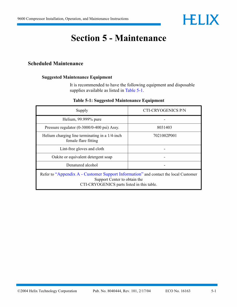
Suggested Maintenance Equipment
It is recommended to have the following equipment and disposable supplies available as listed in Table 5-1.
Table 5-1: Suggested Maintenance Equipment
Supply CTI-CRYOGENICS P/N
Helium, 99.999% pure -
Pressure regulator (0-3000/0-400 psi) Assy. 8031403
Helium charging line terminating in a 1/4-inchfemale flare fitting
7021002P001
Lint-free gloves and cloth -
Oakite or equivalent detergent soap -
Denatured alcohol -
Refer to “Appendix A - Customer Support Information” and contact the local Customer Support Center to obtain the
CTI-CRYOGENICS parts listed in this table.
4 Helix Technology Corporation Pub. No. 8040444, Rev. 101, 2/17/04 ECO No. 16163 5-1

Scheduled Maintenance ELIXH
5-2
Adsorber Replacement
Use the following procedure to change the adsorber every three years.
1. Set the System Circuit Breaker, on the rear of the 9600 Compressor, to the OFF position.
2. Remove the 4 screws which secure the rear panel to the Compressor and remove the rear panel.
NOTE: Use two wrenches in Step 3 to prevent loosening the body of the coupling.
3. Using a 1-3/16 in. wrench, and a 1-1/8 in. wrench, as shown in Figure 5-1, disconnect the two self sealing coupling connectors quickly to minimize helium leakage.
Figure 5-1: Disconnecting Self Sealing Couplings
4. Using a 7/16 in. (11mm) wrench, remove the adsorber mounting bolt as shown in Figure 5-2.
5. Move the adsorber from under the mounting tabs in the base as shown in Figure 5-2 and remove the adsorber from the Compressor.
6. Install the replacement adsorber under the mounting tabs and secure it into place with the bolt removed during Step 4.
7. Using two wrenches as shown in Figure 5-1, connect the two self sealing couplings quickly to minimize helium leakage.
8. Install the Compressor rear panel.
This 1 3/16 in. wrench is used to turn the self sealing coupling
This 1 1/8 in. wrench holds the coupling in a stationary position. Side View
To Tighten Coupling Halves
Hold HereTurn Here
Hold Here Turn Here
To Loosen Coupling Halves
©2004 Helix Technology Corporation Pub. No. 8040444, Rev. 101, 2/17/04 ECO No. 16163

9600 Compressor Installation, Operation, and Maintenance Instructions ELIXH
©200
9. Ensure that the pressure gauge reads the proper value as shown in Table 4-1. If additional gas pressure is required, refer to “Adding Helium” in this section. If gas pressure needs to be reduced, refer to “Reducing Helium Pressure” in this section.
10. Record the adsorber replacement date on the label as shown in Figure 5-2, and also note that the next adsorber replacement should be performed every three years.
Figure 5-2: Adsorber Location, 9600 Compressor (Rear Panel Removed)
Adsorber Mounting Bolt
Adsorber
DATE
4 Helix Technology Corporation Pub. No. 8040444, Rev. 101, 2/17/04 ECO No. 16163 5-3

Adjusting System Helium Pressure ELIXH
5-4
Adjusting System Helium PressureNOTE: These procedures can be performed on a compressor that is turned ON or OFF. However, the helium pressure gauge should be set to the ("OFF" Condition) helium charge pressure value if the compressor is turned OFF or set to the normal system operating pressure if the compressor is turned ON. Refer to “Section 4 - Operation” for more information.
Reducing Helium Pressure
NOTE: You must obtain the normal system operating pressure from the “Compressor Operation” procedure in “Section 4 - Operation” in order to perform this procedure. If the normal system operating pressure is unknown, then shut the compressor OFF and perform the “"OFF" Condition Helium System Pressure Verification” procedure in “Section 4 - Operation” instead.
1. Remove the flare cap from the gas charge fitting as shown in Figure 5-3.
Figure 5-3: Helium Pressure Control Components
2. Open the gas charge control valve very slowly to allow a slight amount of helium to escape. Leave the valve open until the helium pressure gauge indicates one of the following:
• To the appropriate value in Table 4-1 if the compressor is OFF and acclimated to a temperature between 60º F and 80º F (15.5º C - 26.6º C).
Gas Charge Flared Fitting
Helium Pressure Gauge
Rear Panel
Gas ChargeControl Valve
©2004 Helix Technology Corporation Pub. No. 8040444, Rev. 101, 2/17/04 ECO No. 16163

9600 Compressor Installation, Operation, and Maintenance Instructions ELIXH
©200
• To the value previously recorded in the “Compressor Operation” procedure in “Section 4 - Operation” if the compressor is ON.
3. Close the gas charge control valve and install the flare cap.
Increasing Helium Pressure
Use the following procedure to increase the helium pressure if the indicated pressure is below the appropriate value as shown in Table 4-1.
Adding Helium
NOTE: You must obtain the normal system operating pressure from the “Compressor Operation” procedure in “Section 4 - Operation” in order to perform this procedure. If the normal system operating pressure is unknown, then shut the compressor OFF and perform the “"OFF" Condition Helium System Pressure Verification” procedure in “Section 4 - Operation” instead.
This procedure ensures that both the regulator and the charging line will be purged of air and that the air trapped in the regulator will not diffuse back into the helium bottle. For best results, CTI-CRYOGENICS suggests a dedicated helium bottle, regulator, and line, which are never separated, for adding helium.
NOTE: You are required to supply the helium charging line terminating in a 1/4-inch female flare fitting, and a two-stage pressure regulator rated at 0-3000/0-400 psig for this operation.
1. Attach a regulator (0-3000/0-400 psig) and charging line to a helium bottle (99.999% pure).
CAUTIONIf helium is being added more than once every several months, check for leaks caused by improperly connected self-sealing connections or any mechanical joint in the Compressor.
CAUTIONUse only 99.999% pure helium gas. Helium circuit contamination may result if a lower quality of helium is used.
4 Helix Technology Corporation Pub. No. 8040444, Rev. 101, 2/17/04 ECO No. 16163 5-5
Adjusting System Helium Pressure ELIXH
5-6
NOTE: Do not open the bottle at this time.
2. Purge the regulator and charging lines as follows:a. Open the regulator a small amount by turning the adjusting
knob clockwise until it contacts the diaphragm, then turn approximately 1/8 to 1/4 turn more, so that the regulator is barely open.
b. Loosely connect the charge line to the helium pressure regulator.
c. Slowly open the bottle valve, and purge the regulator and line for 10 to 15 seconds. Turn the regulator knob counterclockwise until the helium stops flowing.
3. Remove the flare cap of the gas charge flared fitting on the rear of the Compressor.
4. Loosely connect the charging line from the helium pressure regulator to the 1/4-inch male flare fitting installed on the helium charge valve. Purge the charge line again, as in step a, for 30 seconds, and tighten the charge line flare fitting onto the gas charge fitting while the helium is flowing.
5. Set the helium pressure regulator to 300 psig (20.7 bars). If the compressor is ON, proceed with step a. If the compressor is OFF, proceed with step b.a. Obtain the previously recorded normal system operating
pressure from the “Compressor Operation” procedure in “Section 4 - Operation”. Open the gas charge control valve very slowly and allow helium to flow until the compressor gauge reading is the same as the value obtained from “Section 4 - Operation”. Quickly close the gas charge control valve.
b. Obtain the appropriate (50 or 60 Hz) ("OFF" Condition) system operating pressure from Table 4-1. Open the gas charge control valve very slowly and allow helium to flow until the compressor gauge reading is the same as the appropriate value in Table 4-1. Quickly close the gas charge control valve.
6. Ensure that the helium charge valve on the Compressor is tightly closed. Shut off the helium pressure regulator on the helium bottle and remove the charging line from the male flare fitting. Reinstallthe flare cap.
©2004 Helix Technology Corporation Pub. No. 8040444, Rev. 101, 2/17/04 ECO No. 16163

ELIXH
©200
Appendix A - Customer Support Information
Customer Support Center LocationsTo locate a Customer Support Center near you, please visit our website www.helixtechnology.com on the world wide web and select CONTACT on the home page.
Guaranteed Up-Time Support (GUTS) For 24 hour, 7 day per week Guaranteed Up-Time Support (GUTS) dial:
800-367-4887 - Inside the United States of America
508-337-5599 - Outside the United States of America
Product Information
Please have the following information available when calling so that we may assist you:
• Product Part Number
• Product Serial Number
• Product Application
• Specific Problem Area
• Hours of Operation
• Equipment Type
• Vacuum System Brand/Model/Date of Manufacture
E-mailFor your convenience, you may also e-mail us at:
4 Helix Technology Corporation A-1


9600 Compressor Installation, Operation, and Maintenance Instructions ELIXH
©200
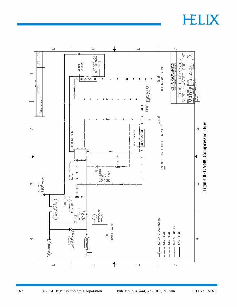
Appendix B - Flow Diagram
Figure B-1 shows the 9600 compressor flow diagram.
4 Helix Technology Corporation Pub. No. 8040444, Rev. 101, 2/17/04 ECO No. 16163 B-1
ELIXH
B-2
Figu
re B
-1: 9
600
Com
pres
s or
Flow
©2004 Helix Technology Corporation Pub. No. 8040444, Rev. 101, 2/17/04 ECO No. 16163

9600 Compressor Installation, Operation, and Maintenance Instructions ELIXH
©200
Appendix C - Troubleshooting Procedures
Troubleshooting the CompressorThe compressor troubleshooting procedures are summarized in Table C-1.
Technical InquiriesPlease refer to “Appendix A - Customer Support Information” of this manual for a complete list of the
CTI-CRYOGENICS’ world wide customer support centers.
WARNINGDisconnect the compressor before performing any troubleshooting procedures.The compressor pump is hot after operating. Wait for the pump to cool down before working on the inside of the compressor
Do not change or modify any compressor internal wiring circuits, this may cause failure of the compressor and cold head due to improper phasing.
4 Helix Technology Corporation Pub. No. 8040444, Rev. 101, 2/17/04 ECO No. 16163 C-1

Technical Inquiries ELIXH
C-2
Table C-1: Compressor Troubleshooting Procedures
Problem Possible Cause Corrective Action
1) System circuit breaker (CB1) trips immediately to the OFF (0) position when switched to the ON (1) position.
1) Incorrect phasing of input power.
1) Check phasing of input power. Refer to “Phase Check” in “Section 3 - Installation”.
2) System (CB1) and Control Circuit (CB2) circuit break-ers remain in the ON (1) position when switched ON but the compressor will not run.
1) No power coming from source.
2) Insufficient power
3) Remote control jumper plug not in place. This will apply only if remote circuit is not being used.
4) Improperly wired external remote control circuit. NOTE: Only applies if remote control feature is being used.
1) Check source fuses, circuit breakers, and wiring asso-ciated with the power source. Repair as needed.
2) Verify adequate phase-to-phase input voltage. Refer to Table 1-2.
3) Check to insure that remote jumper plug is fully seated. See Figure 1-4 for loca-tion. Refer to “Compres-sor Remote Connector” in “Section 1 - 9600 Compressor Descrip-tion” for more information.
4) Verify correct installation of remote control feature. Refer to Table 1-6.
©2004 Helix Technology Corporation Pub. No. 8040444, Rev. 101, 2/17/04 ECO No. 16163

9600 Compressor Installation, Operation, and Maintenance Instructions ELIXH
©200
3) System circuit breaker (CB1) will not remain in the ON (1) position when switched ON. The Control Circuit circuit breaker (CB2) trips when exces-sive current is being drawn by the cold head or 24 volt compressor control cir-cuits.
1) Damaged On-Board power cable, connectors, or drive motor.
2) Damaged component in the compressor power or control circuit.
1) Check for compressor oper-ation with cryopump cable disconnected from compres-sor. Refer to “Appendix A - Customer Support Infor-mation” to contact the Cus-tomer Support Center if the compressor operates improperly.
2) Refer to “Appendix A - Customer Support Infor-mation” to contact the Cus-tomer Support Center.
4) System circuit breaker (CB1) remains in the ON (1) position and the com-pressor stops after several minutes of operation and remains OFF (0).
1) Thermal protective switches are open.
3) Very cold water has caused a restriction of oil flow through the oil injection orifice dur-ing start-up.
1) Check for inadequate water cooling. Refer to Table 1-3.
3) Recheck for proper cooling water temperature. Refer to Table 1-3. Restart compres-sor repeatedly until continu-ous operation is achieved.
5) System circuit breaker (CB1) trips after a period of running.
1) Loss or degradation of power from the source.
2) Defective motor windings.
1) Check that line voltage is correct on all phases.
2) Check running current on all phases.
3) Refer to “Appendix A - Customer Support Infor-mation” to contact the local Customer Support Center.
Table C-1: Compressor Troubleshooting Procedures (Continued)
Problem Possible Cause Corrective Action
4 Helix Technology Corporation Pub. No. 8040444, Rev. 101, 2/17/04 ECO No. 16163 C-3


9600 Compressor Installation, Operation, and Maintenance Instructions ELIXH
©200
Appendix D - Schematic
IntroductionThe schematic in Appendix C supports the 9600 (Low Voltage) Compressor CTI-CRYOGENICS P/N 8135164P001.
Table D-2: Basic Control Assembly Legend
Identifier Description
1M Compressor Motor
J15 Module Power Receptacle
J1/P1 Autoset Power Connector
J2/P2 Unload Solenoid Connector
J3/P3 Oil Solenoid Connector
J4/P4
J5/P5
J6/P6 Compressor Contactor Coil
J7/P7 Output Connector
CB1 Main Circuit Breaker (25A)
CB2 Control Circuits Circuit Breaker (7A)
ETM1 Elapsed Time Meter
M1 Contactor 7.5 HP IEC
M1OL Relay, Overload (16-24A)
PM1 Phase Monitor OMRON RDR-TFY-M
PWB1 PWB Autoset
T4 Transformer Assembly Control
LT1 Lamp, 24-28V LED Green
J8/P8 ETM1 Connector
J9/P9 LT1 Connector
J10/P10 T3 Input Connector
4 Helix Technology Corporation Pub. No. 8040444, Rev. 101, 2/17/04 ECO No. 16163 D-1

Introduction ELIXH
D-2
J11 Open
J12 Module Signal Connector
J13/P13 Phase Monitor
J14 Open
J15 Cryo Power Output
K2 Over Temperature Lockout Relay
Table D-3: On-Board/Cryo Electrical Module P/N 8135127G001 Legend
Identifier Description
JT1 Open
JT2 Open
JT3/PT3 T2 Cold Head Supply, 2 phase
JT4/PT4 T1 Cold Head Supply, 2 phase
JT5/PT5 T2 Cold Head Transformer Output
JT6/PT6 T1 Cold Head Transformer Output
JT7/PT7 T3 Supply
JT8/PT8 T3 Low Voltage Output (23/26 VCT)
J18 Power Output
J19 Signal Output
P12 Signal Connector
P15 Power Connector
K1 Cold Head Voltage Relay
K2 Signal Voltage Relay
K3 Cryo Power Relay
T1 Cold Head Supply
T2 Cold Head Supply
T3 Low Voltage Supply
Table D-2: Basic Control Assembly Legend (Continued)
Identifier Description
©2004 Helix Technology Corporation Pub. No. 8040444, Rev. 101, 2/17/04 ECO No. 16163
9600 Compressor Installation, Operation, and Maintenance Instructions ELIXH
©200
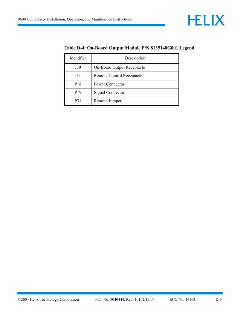
Table D-4: On-Board Output Module P/N 8135148G001 Legend
Identifier Description
J30 On-Board Output Receptacle
J31 Remote Control Receptacle
P18 Power Connector
P19 Signal Connector
P31 Remote Jumper
4 Helix Technology Corporation Pub. No. 8040444, Rev. 101, 2/17/04 ECO No. 16163 D-3


D-5
3ph 3ph4 1 2 3 4 1 2 3 4
1 2 3 4 1 2 3 4
4 5
2 3 4 2 3 4
BLKRED
WHT/REDWHT/ORN
BRNVIOGRAYEL
GRN/YEL
JP1 BLUWHT/BLU
BB
LU
1
YE
LO
RN
RE
D
BLU
1
YE
LO
RN
RE
D
12345678
J18
123456
12345678
123456
ABCDEFGHJK
AB
A
REVISIONS
REV DATE APPROVEDDESCRIPTION
DWG NO
SHEET OF
CAGE CODE
31949
SIZE
DATEBY
REV
B1 1
1
1
CTI-CRYOGENICSHELIX TECHNOLOGY CORPORATION
D
C
B
A
5
1 2 3 4 1 2 3 4
GRA
GRA
BLK
BLK
ON-BOARD OUTPUT MODULE J30
WHT/GRAWHT/BLK
WHT/GRAWHT/BLK
J31
P31
SCHEMATIC, 9600COMPRESSOR, LOW VOLTAGE
KM
VG
GW
DP
8135164P001 100
100 REVISED PER ECO 16163 HH HH1/04
REMOTE
P19J19
JT5
JT2
JT3
JT4
JT1
BLK
WHT
YEL
WHT/ORN
WHT/YEL
8135148G001
PT5
PT6
JT6
80
82
84
86
88
90
94
96
98
92
100
102
104
110
112
114
118
106
108
126
128
130
122
120
P18
T2
1 2 3 4
ABCN
T2
1 2 3 4
ABCN
T1
1 2 3 4
ABCN
T1
1 2 3 4
ABCN
K1K1
K3K3
P/N 8040444
BLK
GRN/YEL #12
W/RED1
12 3
2 312 31
24ACHI
RED
WHT
VIOWHT
BLK
25A
YE
L RE
D
W/R
EDB
LU
BLK
OR
NR
ED
J12
1
3
5
2
4
6 WHT
GRN/YELWHT/REDWHT/BLUWHT/ORNWHT/BRN
YELRED
BLK
GRN/YEL
ENG APPVL
DRAWN
CHECKED
ENG APPVL
QA APPVL
PROD
PRE-PROD
2
23
34
4
A
B
D
C
ENG APPVP
AUTOSET
COMPRESSOR
RED #12
YEL #12
BLK #12
RED #12
YEL #12
BLK #12
POWER AUTOSET BD
BASIC CONTROL ASSY LO VOLT
1 2 3 41 2 3 4
1 2 3 4
1 2 3 4
1 2 3 4
1 2 3 4
J1
P1 J13
P13
J10
P10
J15
J11
UNLOAD
SOL1
SOL2
OIL
.02A
P15
1532
1235
1 1
2 2
1 1
2 2
1 122
1 122
J5
J4
J3
J2
P5
P4
P3
P2
1234
SMOD
TS1
TS2
T4
1 4
JT7
PT7
2 1 3 4JT8
M1OL
8135167G001
P12
123456
JP1
J7
P7
11
2 2 P14J14
A
CN.O.
He
Water
CompTS3
ON-BD/CRYO ELEC MOD
R S T
EXCEPT AS OTHERWISE AGREEDIN WRITING, THE INFORMATIONAND DESIGN DISCLOSED HEREINARE THE PROPERTY OFCTI-CRYOGENICS AND MUST NOTBE COPIED OR DISTRIBUTEDOUTSIDE CTI-CRYOGENICSEXCEPT TO AUTHORIZED PERSONSWITH A GENUINE NEED-TO-KNOWWHO BY THE USE HEREOF ACKNOW-LEDGE CTI-CRYOGENICS OWNER-SHIP AND AGREE TO MAINTAINTHIS INFORMATION AND DESIGNIN STRICT CONFIDENCE.
PROPRIETARY NOTICE
SELLER'S GOODS SHALL NOT BE MANUFACTUREDWITH OR CONTAIN CLASSI ODS'S AS DEFINED UNDER SECTION 602 OFTHE FEDERAL CLEAN AIR ACT (42 USC SECTION
ENVIRONMENTAL STATEMENT
7671A) OR ANY NEW APPLICABLEREGULATIONS.
8135132G002
PM1
X Y Z GND
MODULE
PT8
REDORN
8135143G001
8135127G001
P4 V
W
U
M1
T1
T2
T3
PHASE OR O/L;TRIPS BREAKER
OPENS CONTACTORPOWER DOWN TO RESET
OPENS CONTACTOR
TS;
REMOTE OR SMOD;
20
22
50
5
26
32
36
40
56
60
13
1
9
11
16
28
52
46
48
42
54
58
62
65
69
73ETM
BRN
WHT
ORCAD V7.11
CAD FILENAME: 8135164P001.DSN
200-230VAC, 16A
CB1
P3
CB1
P3 P2P2 P1P1
M1OL97 98M1OL97 98
CB2R
U
CB2R
U
S
V
S
V
LT1LT1
T
W
T
W
12
12
K2AK2A
34
34
K2AK2A
M1
56
M1
56
M1M1
T3225
02326
T3225
02326
M1
1314
M1
1314
K2K2
K2BK2B
J6
12
J6
12
P6
12
P6
12
J9
12
J9
12
J8
12
J8
12
P8
12
P8
12
P9
12
P9
12
K2K2
Figure D-1: 9600 Compressor (Low Voltage) Schematic

©200
ELIXHIndex
AAdsorbers
replacing, 5-2
CCircuit breaker
system, 1-9Components
compressor remote connector, 1-11control circuit breaker, 1-9cooling water IN, 1-10cryopump electrical outlet, 1-10description, 1-7elapsed time meter, 1-9gas charge flared fitting, 1-9helium pressure gauge, 1-10multiple Cryo-Torr connections, 1-12multiple on-board cryopump
connections, 1-12power inlet, 1-10power on indicator, 1-9return gas coupling, 1-10system circuit breaker, 1-9
Compressorconfigurations, 1-1description, 1-1remote connector, 1-11starting, 4-2
Compressor safety, S-1Connecting/disconnecting helium lines, 3-7Connections
single On-Board, 3-8Control circuit breaker, 1-9Cooling water, 1-6
IN, 1-10Cryopump
electrical outlet, 1-10
DDocumentation
4 Helix Technology Corporation Pub. No. 8040444,
system, 1-1
EElapsed time
meter, 1-9Electrical connections
installing, 3-4
FFlow diagram, B-1
GGas charge
flared fitting, 1-9
HHelium
adding, 5-5Helium circuit components
replacing, 4-3Helium flex lines
connecting/disconnecting, 3-7Helium pressure
adjusting, 4-1gauge, 1-10
Helium refrigeration systemoverview, 1-1
Helium system pressureadjusting, 5-4increasing, 5-5reducing, 5-4verifying OFF condition, 4-1
IInstalling the compressor, 3-1–3-16
MMaintenance
scheduled, 5-1Maintenance procedures, 5-1–5-6
Rev. 101, 2/17/04 ECO No. 16163 Index-1
ELIXH
Index
Multiple connections, 1-12Cryopump, 1-12
Multiple Cryo-Torr connections, 3-14Multiple On-Board connections, 3-11
OOFF Condition
helium system pressure verification, 4-1Operating the compressor, 4-1
PPhase check
performing, 3-6Power inlet, 1-10Power on indicator, 1-9
RReturn gas coupling, 1-10
SSafety
compressor, S-1Schematic
control assembly legend, D-1On-Board Cryo electrical, D-2On-Board output module legend, D-3
Schematic diagram, D-1Single On-Board connections, 3-8Specifications, 1-3Starting the compressor, 4-2Supply and return water connections
installing, 3-3
TTroubleshooting, C-1–C-3
UUnpacking, 2-1–2-2
WWater
cooling, 1-6
-2 ©2004 Helix Technology Corporation Pub
. No. 8040444, Rev. 101, 2/17/04 ECO No. 16163