94/25/ec as amended by directive 2003/44/ec propulsion ... · pdf filestarter motor will not...
TRANSCRIPT

eng i
Declaration of Conformity – For Recreational CraftPropulsion Engines with the Requirements of Directive94/25/EC as amended by Directive 2003/44/EC
Name of engine manufacturer: Mercury MarineAddress: W6250 W. Pioneer Road, P.O. Box 1939Town: Fond du Lac, WI Post Code: 54936‑1939 Country: USA
Name of Authorized Representative: Brunswick Marine in EMEA Inc.Address: Parc Industriel de Petit‑RechainTown: Verviers Post Code: B‑4800 Country: Belgium
Name of Notified Body for exhaust emission assessment: DetNorske Veritas ASAddress: Veritasveien 1
Town: Hovik Post Code:1322
Country:Norway ID Number: 0575
Name of Notified Body for noise emission assessment: Det NorskeVeritas ASAddress: Veritasveien 1
Town: Hovik Post Code:1322
Country:Norway ID Number: 0575
Conformityassessment moduleused for exhaustemissions:
☐ B+C ☐ B+D ☐ B+E ☐ B+F ☐ G ☒ H
Conformityassessment moduleused for noiseemissions:
☐ A ☐ Aa ☐ G ☒ H
Other Community Directives applied: Safety of Machinery Directive2006/42/EC; Electromagnetic Compatibility Directive 2004/108/EC
Description of Engines and Essential Requirements
Engine Type Fuel Type Combustion Cycle☒ Outboard engine ☒ Petrol ☒ 2 stroke
© 2
013
Mer
cury
Mar
ine
200-
250
Opt
iMax
Incl
udin
g Pr
o XS
90-8
M00
8700
0 12
13

ii eng
Identification of Engines Covered by This Declaration of Conformity
Name of engine family
Unique engineidentificationnumber(s) or enginefamily code(s):starting serial number
Module HCertificate
1.5L OptiMax 75, 90, 115, 115Pro XS, 125 hp, 80 Jet 0B228000 RCD‑H‑2 Rev 4
2.5L OptiMax 135, 150, 150Pro XS, 175 hp 0B228000 RCD‑H‑2 Rev 4
3.0L OptiMax 200, 200 Pro XS,225, 250 hp 0B228000 RCD‑H‑2 Rev 4
Essentialrequirements Standards
Othernormativedocument/
method
Technicalfile
Please specify inmore detail(* = mandatorystandard)
Annex 1.B—Exhaust EmissionsB.1 engineidentification ☐ ☐ ☒
B.2 exhaustemissionrequirements
☒* ☐ ☐ * EN ISO8178‑1:1996
B.3 durability ☐ ☐ ☒
B.4 owner'smanual ☒ ☐ ☐ ISO 8665: 2006
Annex 1.C—Noise EmissionsC.1 Noiseemission levels ☒* ☐ ☐ EN ISO 14509
C.2 Owner'smanual ☐ ☒ ☐ Owner's manual
This declaration of conformity is issued under the sole responsibility of themanufacturer. I declare on behalf of the engine manufacturer that the enginesmentioned preceding complies with all applicable essential requirements inthe way specified.

eng iii
Name / function:Mark D. Schwabero, PresidentMercury Marine
Date and place of issue:February 04, 2013Fond du Lac, Wisconsin, USA
WelcomeYou have selected one of the finest outboards available. It incorporatesnumerous design features to ensure operating ease and durability.With proper care and maintenance, you will enjoy using this product for manyboating seasons. To ensure maximum performance and carefree use, we askthat you thoroughly read this manual.The Operation, Maintenance and Warranty Manual contains specificinstructions for using and maintaining your product. We suggest that thismanual remain with the product for ready reference whenever you are on thewater.Thank you for purchasing one of our products. We sincerely hope your boatingwill be pleasant!Mercury Marine
EPA Emissions RegulationsOutboards sold by Mercury Marine in the United States are certified to theUnited States Environmental Protection Agency as conforming to therequirements of the regulations for the control of air pollution from newoutboard motors. This certification is contingent on certain adjustments beingset to factory standards. For this reason, the factory procedure for servicing theproduct must be strictly followed and, wherever practicable, returned to theoriginal intent of the design. Maintenance, replacement, or repair of theemission control devices and systems may be performed by any marine enginerepair establishment or individual.Engines are labeled with an emission control information decal as permanentevidence of EPA certification.
! WARNINGThe engine exhaust from this product contains chemicals known to the stateof California to cause cancer, birth defects or other reproductive harm.

iv eng
Warranty MessageThe product you have purchased comes with a limited warranty from MercuryMarine. The terms of the warranty are set forth in the Warranty Informationsection of this manual. The warranty statement contains a description of what iscovered, what is not covered, the duration of coverage, how to best obtainwarranty coverage, important disclaimers and limitations of damages, and otherrelated information. Please review this information.The description and specifications contained herein were in effect at the timethis manual was approved for printing. Mercury Marine, whose policy is one ofcontinued improvement, reserves the right to discontinue models at any time,and to change specifications, designs, methods, or procedures without noticeand without incurring obligation.Mercury Marine, Fond du Lac, Wisconsin U.S.A.
Mercury Premier ServiceMercury evaluates the service performance of its dealers and assigns itshighest rating of Mercury Premier to those demonstrating an exceptionalcommitment to service.Earning a Mercury Premier Service rating means a dealer:• Achieves a high 12‑month service Customer Satisfaction Index (CSI)
score for warranty service.• Possesses all of the necessary service tools, test equipment, manuals,
and parts books.• Employs at least one certified or master technician.• Provides timely service for all Mercury Marine customers.• Offers extended service hours and mobile service, when appropriate.• Uses, displays, and stocks an adequate inventory of genuine Mercury
Precision Parts.• Offers a clean, neat shop with well‑organized tools and service literature.
Copyright and Trademark Information© MERCURY MARINE. All rights reserved. Reproduction in whole or inpart without permission is prohibited.Alpha, Axius, Bravo One, Bravo Two, Bravo Three, Circle M with Waves Logo,K‑planes, Mariner, MerCathode, MerCruiser, Mercury, Mercury with WavesLogo, Mercury Marine, Mercury Precision Parts, Mercury Propellers, MercuryRacing, MotorGuide, OptiMax, Quicksilver, SeaCore, Skyhook, SmartCraft,Sport‑Jet, Verado, VesselView, Zero Effort, Zeus, #1 On the Water and We'reDriven to Win are registered trademarks of Brunswick Corporation. Pro XS is atrademark of Brunswick Corporation. Mercury Product Protection is a registeredservice mark of Brunswick Corporation.
eng v
WARRANTY INFORMATION
Warranty Registration United States and Canada.............................................. 1Transfer of Warranty United States and Canada................................................1Transfer of Mercury Product Protection (Extended Service Coverage) PlanUnited States and Canada..................................................................................23 Year Limited Warranty Against Corrosion....................................................... 2Warranty Coverage and Exclusions................................................................... 4U.S. EPA Emissions Limited Warranty............................................................... 6Emission Control System Components.............................................................. 6California Emissions Limited Warranty............................................................... 7California Air Resources Board Explanation of Your California Emission ControlWarranty Statement............................................................................................ 9Emission Certification Star Label...................................................................... 10Warranty Policy—Australia and New Zealand.................................................. 11Global Warranty Charts Outboard and Jets......................................................15
General Information
Boater's Responsibilities................................................................................... 20Before Operating Your Outboard...................................................................... 20Boat Horsepower Capacity............................................................................... 20High‑Speed and High‑Performance Boat Operation........................................ 21Outboard Remote Control Models ................................................................... 21Propeller Selection............................................................................................22Remote Steering Notice....................................................................................24Lanyard Stop Switch......................................................................................... 24Protecting People in the Water......................................................................... 27Passenger Safety Message ‑ Pontoon Boats and Deck Boats.........................27Wave and Wake Jumping................................................................................. 29Impact with Underwater Hazards......................................................................30Exhaust Emissions........................................................................................... 31Selecting Accessories for Your Outboard......................................................... 33Safe Boating Recommendations...................................................................... 33Recording Serial Number................................................................................. 35200/200 Pro XS OptiMax Specifications........................................................... 36225/250 Pro XS Specifications......................................................................... 37250 OptiMax Specifications.............................................................................. 38Component Identification.................................................................................. 39
Transporting
Trailering Boat/Outboard ................................................................................. 40

vi eng
Fuel and Oil
Fuel Recommendations.................................................................................... 41Oil Recommendation........................................................................................ 42Fuel Additives................................................................................................... 42Fuel Requirements........................................................................................... 42Avoiding Fuel Flow Restriction......................................................................... 43Low Permeation Fuel Hose Requirement ........................................................ 43EPA Pressurized Portable Fuel Tank Requirements........................................ 43Fuel Demand Valve (FDV) Requirement.......................................................... 43Mercury Marine's Pressurized Portable Fuel Tank........................................... 44Filling Remote Oil Tank.................................................................................... 45Filling Engine Mounted Oil Reservoir Tank...................................................... 45Filling Fuel Tank............................................................................................... 46
Features and Controls
Remote Control Features................................................................................. 47Warning System............................................................................................... 47Power Trim and Tilt...........................................................................................50
Operation
Important Information........................................................................................54Engine Break‑in................................................................................................ 55Engine Break‑in Fuel Mixture........................................................................... 55Prestarting Check List.......................................................................................55Operating in Freezing Temperatures................................................................ 56Operating in Saltwater or Polluted Water......................................................... 56Operating at High Elevations............................................................................ 56Effects of Elevation and Weather on Performance........................................... 56Setting Trim Angle While Running Engine at Idle Speed................................. 57Operating in Shallow Water.............................................................................. 57Starting the Engine........................................................................................... 58Gear Shifting..................................................................................................... 61Stopping the Engine......................................................................................... 61

eng vii
Maintenance
Outboard Care.................................................................................................. 62EPA Emissions Regulations............................................................................. 62Inspection and Maintenance Schedule............................................................. 63Flushing the Cooling System............................................................................ 66Top Cowl Removal and Installation.................................................................. 66Cleaning Care for Top Cowl............................................................................. 67Alternator Belt Inspection..................................................................................67Fuel System...................................................................................................... 68Steering Link Rod Fasteners............................................................................ 70Fuses ............................................................................................................... 71Corrosion Control Anode.................................................................................. 72Battery Inspection ............................................................................................ 73Battery Information (All Batteries Including DTS)............................................. 73Propeller Replacement..................................................................................... 74Spark Plug Inspection and Replacement..........................................................78Air Compressor Filter........................................................................................ 79Lubrication Points............................................................................................. 81Checking Power Trim Fluid...............................................................................84Gearcase Lubrication........................................................................................85Submerged Outboard....................................................................................... 86
Storage
Storage Preparation..........................................................................................87Fuel System...................................................................................................... 87Protecting Internal Engine Components........................................................... 89Protecting External Outboard Components...................................................... 89Gearcase.......................................................................................................... 89Positioning Outboard for Storage..................................................................... 89Battery Storage................................................................................................. 90
Troubleshooting
Starter Motor Will Not Crank the Engine...........................................................91Engine Will Not Start.........................................................................................91Engine Runs Erratically.................................................................................... 91Performance Loss.............................................................................................92Warning Horn Activates (With Power Loss)...................................................... 92Warning Horn Activates (No Power Loss)........................................................ 92Battery Will Not Hold Charge............................................................................ 93

viii eng
Owner Service Assistance
Local Repair Service.........................................................................................94Service Away from Home................................................................................. 94Parts and Accessories Inquiries....................................................................... 94Service Assistance........................................................................................... 94Ordering Literature............................................................................................97
Outboard Installation
Mercury Marine Validated Engine Mounting Hardware.................................... 99Accessories Mounted to the Transom Clamp Bracket...................................... 99Boat Horsepower Capacity............................................................................. 103Start in Gear Protection.................................................................................. 103Selecting Accessories for Your Outboard....................................................... 104Fuel System.................................................................................................... 104Installation Specifications............................................................................... 106Lifting the Outboard........................................................................................ 106Steering Cable ‑ Starboard Side Routed Cable.............................................. 107Steering Link Rod Fasteners.......................................................................... 108Recommended Mounting Height.................................................................... 110Drilling Outboard Mounting Holes................................................................... 113Fastening the Outboard to the Transom......................................................... 114Electrical, Hoses, Control Cables, and Front Clamp...................................... 119Oil Injection Set‑Up......................................................................................... 130Trim In Pin...................................................................................................... 132
Maintenance Log
Maintenance Log............................................................................................ 134
WARRANTY INFORMATION
eng 1
Warranty Registration United States and CanadaTo be eligible for warranty coverage, the product must be registered withMercury Marine.At the time of sale, the selling dealer should complete the warranty registrationand immediately submit it to Mercury Marine via MercNET, e‑mail, or mail.Upon receipt of this warranty registration, Mercury Marine will record theregistration.A copy of the warranty registration should be provided to you by your sellingdealer.NOTE: Registration lists must be maintained by Mercury Marine and any dealerof Mercury Marine products sold in the United States, should a safety recallnotification under the Federal Safety Act be required.You may change your registered address at any time, including at time ofwarranty claim, by calling Mercury Marine or sending a letter or fax with yourname, old address, new address, and engine serial number to MercuryMarine’s warranty registration department. Your dealer can also process thischange of information.Mercury MarineAttn: Warranty Registration DepartmentW6250 Pioneer RoadP.O. Box 1939Fond du Lac, WI 54936-1939920-929-5054Fax +1 920 907 6663
OUTSIDE UNITED STATES AND CANADAFor products purchased outside the United States and Canada, contact thedistributor in your country, or the Marine Power Service Center closest to you.
Transfer of Warranty United States and CanadaThe limited warranty is transferable to a subsequent purchaser, but only for theremainder of the unused portion of the limited warranty. This will not apply toproducts used for commercial applications.To transfer the warranty to the subsequent owner, send or fax a copy of the billof sale or purchase agreement, new owner’s name, address, and engine serialnumber to Mercury Marine’s warranty registration department. In the UnitedStates and Canada, mail to:Mercury MarineAttn: Warranty Registration DepartmentW6250 Pioneer RoadP.O. Box 1939Fond du Lac, WI 54936-1939920-929-5054Fax +1 920 907 6663

WARRANTY INFORMATION
2 eng
Upon processing the transfer of warranty, Mercury Marine will record the newowner's information.There is no charge for this service.
OUTSIDE THE UNITED STATES AND CANADAFor products purchased outside the United States and Canada, contact thedistributor in your country, or the Marine Power Service Center closest to you.
Transfer of Mercury Product Protection (Extended ServiceCoverage) Plan United States and CanadaThe remaining coverage period of the Product Protection Plan is transferable tothe subsequent purchaser of the engine within thirty (30) days from the date ofsale. Contracts not transferred within thirty (30) days of the subsequentpurchase will no longer be valid and the product will no longer be eligible forcoverage under the terms of the contract.To transfer the plan to the subsequent owner, contact Mercury ProductProtection or an authorized dealer to receive a Request for Transfer form.Submit to Mercury Product Protection a receipt/bill of sale, a completedRequest of Transfer form, and a check payable to Mercury Marine in theamount of $50.00 (per engine) to cover the transfer fee.Plan coverage is not transferable from one product to another product or fornoneligible applications.The certified preowned engine plans are not transferable.For help or assistance, contact Mercury Product Protection Department at1‑888‑427‑5373 from 7:30 a.m. to 4:30 p.m. CST, Monday–Friday or e‑[email protected].
3 Year Limited Warranty Against CorrosionWHAT IS COVERED: Mercury Marine warrants that each new Mercury,Mariner, Mercury Racing, Sport‑Jet, M2 Jet Drive, Tracker by Mercury MarineOutboard, Mercury MerCruiser Inboard or Sterndrive Engine (Product) will notbe rendered inoperative as a direct result of corrosion for the period of timedescribed below.DURATION OF COVERAGE: This limited corrosion warranty providescoverage for three (3) years from either the date the product is first sold, or thedate on which the product is first put into service, whichever occurs first. Therepair or replacement of parts, or the performance of service under thiswarranty, does not extend the life of this warranty beyond its original expirationdate. Unexpired warranty coverage can be transferred to subsequent(noncommercial use) purchaser upon proper reregistration of the product.

WARRANTY INFORMATION
eng 3
CONDITIONS THAT MUST BE MET IN ORDER TO OBTAIN WARRANTYCOVERAGE: Warranty coverage is available only to retail customers thatpurchase from a Dealer authorized by Mercury Marine to distribute the productin the country in which the sale occurred, and then only after the MercuryMarine specified predelivery inspection process is completed and documented.Warranty coverage becomes available upon proper registration of the productby the authorized dealer. Corrosion prevention devices specified in theOperation and Maintenance Manual must be in use on the boat, and routinemaintenance outlined in the Operation and Maintenance Manual must be timelyperformed (including, without limitation, the replacement of sacrificial anodes,use of specified lubricants, and touch‑up of nicks and scratches) in order tomaintain warranty coverage. Mercury Marine reserves the right to makewarranty coverage contingent upon proof of proper maintenance.WHAT MERCURY WILL DO: Mercury's sole and exclusive obligation underthis warranty is limited to, at our option, repairing a corroded part, replacingsuch part or parts with new or Mercury Marine certified remanufactured parts,or refunding the purchase price of the Mercury product. Mercury reserves theright to improve or modify products from time to time without assuming anobligation to modify products previously manufactured.HOW TO OBTAIN WARRANTY COVERAGE: The customer must provideMercury with a reasonable opportunity to repair, and reasonable access to theproduct for warranty service. Warranty claims shall be made by delivering theproduct for inspection to a Mercury dealer authorized to service the product. Ifpurchaser cannot deliver the product to such a dealer, written notice must begiven to Mercury. We will then arrange for the inspection and any coveredrepair. Purchaser, in that case, shall pay for all related transportation chargesand/or travel time. If the service provided is not covered by this warranty,purchaser shall pay for all related labor and material, and any other expensesassociated with that service. Purchaser shall not, unless requested by Mercury,ship the product or parts of the product directly to Mercury. Proof of registeredownership must be presented to the dealer at the time warranty service isrequested in order to obtain coverage.WHAT IS NOT COVERED: This limited warranty does not cover electricalsystem corrosion; corrosion resulting from damage, corrosion which causespurely cosmetic damage, abuse, or improper service; corrosion to accessories,instruments, steering systems; corrosion to factory installed jet drive unit;damage due to marine growth; product sold with less than a one year limitedProduct warranty; replacement parts (parts purchased by customer); productsused in a commercial application. Commercial use is defined as any work oremployment related use of the product, or any use of the product whichgenerates income, for any part of the warranty period, even if the product isonly occasionally used for such purposes.

WARRANTY INFORMATION
4 eng
Corrosion damage caused by stray electrical currents (onshore powerconnections, nearby boats, submerged metal) is not covered by this corrosionwarranty and should be protected against by the use of a corrosion protectionsystem, such as the Mercury Precision Parts or Quicksilver MerCathodesystem and/or Galvanic Isolator. Corrosion damage caused by improperapplication of copper base antifouling paints is also not covered by this limitedwarranty. If antifouling protection is required, Tri‑Butyl‑Tin‑Adipate (TBTA) baseantifouling paints are recommended on Outboard and MerCruiser boatingapplications. In areas where TBTA base paints are prohibited by law, copperbase paints can be used on the hull and transom. Do not apply paint to theoutboard or MerCruiser product. In addition, care must be taken to avoid anelectrical interconnection between the warranted product and the paint. ForMerCruiser product, an unpainted gap of at least 38 mm (1.5 in.) should be leftaround the transom assembly. Refer to the Operation and Maintenance Manualfor additional details.For additional information regarding events and circumstances covered by thiswarranty, and those that are not, see the Warranty Coverage section of theOperation and Maintenance Manual, incorporated by reference into thiswarranty.
DISCLAIMERS AND LIMITATIONS:
THE IMPLIED WARRANTIES OF MERCHANTABILITY AND FITNESS FORA PARTICULAR PURPOSE ARE EXPRESSLY DISCLAIMED. TO THEEXTENT THAT THEY CANNOT BE DISCLAIMED, THE IMPLIEDWARRANTIES ARE LIMITED IN DURATION TO THE LIFE OF THEEXPRESS WARRANTY. INCIDENTAL AND CONSEQUENTIAL DAMAGESARE EXCLUDED FROM COVERAGE UNDER THIS WARRANTY. SOMESTATES/COUNTRIES DO NOT ALLOW FOR THE DISCLAIMERS,LIMITATIONS AND EXCLUSIONS IDENTIFIED ABOVE, AS A RESULT,THEY MAY NOT APPLY TO YOU. THIS WARRANTY GIVES YOUSPECIFIC LEGAL RIGHTS, AND YOU MAY ALSO HAVE OTHER LEGALRIGHTS WHICH VARY FROM STATE TO STATE AND COUNTRY TOCOUNTRY.
Warranty Coverage and ExclusionsThe purpose of this section is to help eliminate some of the more commonmisunderstandings regarding warranty coverage. The following informationexplains some of the types of services that are not covered by warranty. Theprovisions set forth following have been incorporated by reference into theThree Year Limited Warranty Against Corrosion Failure, the InternationalLimited Outboard Warranty, and the United States and Canada LimitedOutboard Warranty.Keep in mind that warranty covers repairs that are needed within the warrantyperiod because of defects in material and workmanship. Installation errors,accidents, normal wear, and a variety of other causes that affect the productare not covered.

WARRANTY INFORMATION
eng 5
Warranty is limited to defects in material or workmanship, but only when theconsumer sale is made in the country to which distribution is authorized by us.Should you have any questions concerning warranty coverage, contact yourauthorized dealer. They will be pleased to answer any questions that you mayhave.
GENERAL EXCLUSIONS FROM WARRANTY1. Minor adjustments and tune‑ups, including checking, cleaning, or
adjusting spark plugs, ignition components, carburetor settings, filters,belts, controls, and checking lubrication made in connection with normalservices.
2. Factory installed jet drive units ‑ Specific parts excluded from the warrantyare: the jet drive impeller and jet drive liner damaged by impact or wear,and water damaged driveshaft bearings as a result of impropermaintenance.
3. Damage caused by neglect, lack of maintenance, accident, abnormaloperation, or improper installation or service.
4. Haul‑out, launch, towing charges, removal and/or replacement of boatpartitions or material because of boat design for necessary access to theproduct, all related transportation charges and/or travel time, etc.Reasonable access must be provided to the product for warranty service.Customer must deliver product to an authorized dealer.
5. Additional service work requested by customer other than that necessaryto satisfy the warranty obligation.
6. Labor performed by other than an authorized dealer may be covered onlyunder the following circumstances: when performed on emergency basis(providing there are no authorized dealers in the area who can performthe work required or have no facilities to haul‑out, etc., and prior factoryapproval has been given to have the work performed at this facility).
7. All incidental and/or consequential damages (storage charges, telephoneor rental charges of any type, inconvenience or loss of time or income)are the owner's responsibility.
8. Use of other than Mercury Precision or Quicksilver parts when makingwarranty repairs.
9. Oils, lubricants, or fluids changed as a matter of normal maintenance iscustomer's responsibility unless loss or contamination of same is causedby product failure that would be eligible for warranty consideration.
10. Participating in or preparing for racing or other competitive activity oroperating with a racing type lower unit.
11. Engine noise does not necessarily indicate a serious engine problem. Ifdiagnosis indicates a serious internal engine condition which could resultin a failure, condition responsible for noise should be corrected under thewarranty.
12. Lower unit and/or propeller damage caused by striking a submergedobject is considered a marine hazard.

WARRANTY INFORMATION
6 eng
13. Water entering engine through the fuel intake, air intake, or exhaustsystem or submersion.
14. Failure of any parts caused by lack of cooling water, which results fromstarting motor out of water, foreign material blocking inlet holes, motorbeing mounted too high, or trimmed too far out.
15. Use of fuels and lubricants which are not suitable for use with or on theproduct. Refer to the Maintenance section.
16. Our limited warranty does not apply to any damage to our productscaused by the installation or use of parts and accessories which are notmanufactured or sold by us. Failures which are not related to the use ofthose parts or accessories are covered under warranty if they otherwisemeet the terms of the limited warranty for that product.
U.S. EPA Emissions Limited WarrantyConsistent with the obligations created by 40 CFR Part 1045, Subpart B,Mercury Marine provides a five year or 175 hours of engine use warranty,whichever occurs first, to the retail customer, that the engine is designed, built,and equipped so as to conform at the time of sale with applicable regulationsunder section 213 of the Clean Air Act, and that the engine is free from defectsin materials and workmanship that cause the engine to fail to conform withapplicable regulations. This emission‑related warranty covers all thecomponents listed in the Emission Control System Components.
Emission Control System ComponentsThe EPA and California emission‑related warranty covers all the following list ofcomponents:
COMPONENTS OF THE EMISSIONS CONTROL SYSTEM:1. Fuel metering system
a. Carburetor and internal parts (and/or pressure regulator or fuelinjection system)
b. Cold start enrichment systemc. Intake valves
2. Air induction systema. Intake manifoldb. Turbocharger or supercharger systems (where applicable)
3. Ignition systema. Spark plugsb. Magneto or electronic ignition systemc. Spark advance/retard systemd. Ignition coil and/or control modulee. Ignition wires
4. Lubrication system (4‑Stroke engines excluded)

WARRANTY INFORMATION
eng 7
a. Oil pump and internal partsb. Oil injectorsc. Oil meter
5. Exhaust systema. Exhaust manifoldb. Exhaust valves
6. Miscellaneous items used in above systemsa. Hoses, clamps, fittings, tubing, sealing gaskets or devices, and
mounting hardwareb. Pulleys, belts, and idlersc. Vacuum, temperature, check and time sensitive valves and switchesd. Electronic controls
The emission‑related warranty does not cover components whose failure wouldnot increase an engine's emissions on any regulated pollutant.
California Emissions Limited WarrantyThe California Air Resources Board has promulgated air emission regulationsfor outboard engines. The regulations apply to all outboard engines sold toretail consumers in California, and which were manufactured for the 2001model year and later. Mercury Marine, in compliance with those regulations,provides this limited warranty for the emission control systems (see thecomponents listed in the Emission Control System Components), andfurther warrants that the outboard engine was designed, built, and equipped toconform with all applicable regulations adopted by the California Air ResourcesBoard pursuant to its authority in Chapters 1 and 2, Part 5, Division 26 of theHealth and Safety Code. For information regarding the limited warranty for thenonemission‑related components of the outboard, please see the limitedwarranty statement for your outboard.WHAT IS COVERED: Mercury Marine warrants the components of theemissions control systems (see the components listed in the Emission ControlSystem Components) of its new, 2001 model year and later outboards, soldby a California dealer to retail customers residing in California, to be free fromdefects in material or workmanship, that cause the failure of a warranted part tobe identical in all material respects to that part as described in the application ofMercury Marine for certification from the California Air Resources Board, for theperiod of time, and under the conditions, identified below. The cost to diagnosea warranty failure is covered under the warranty (if the warranty claim isapproved). Damage to other engine components caused by the failure of awarranted part will also be repaired under warranty.

WARRANTY INFORMATION
8 eng
DURATION OF COVERAGE: This limited warranty provides coverage for thecomponents of the emissions control systems of new, 2001 model year andlater outboards, sold to retail customers in California for four (4) years fromeither the date the product is first sold, or first put into service, whicheveroccurs first, or the accumulation of 250 hours of engine operation (asdetermined by the engine's hour meter, if any). Emission‑related normalmaintenance items such as spark plugs and filters, that are on the warrantedparts list, are warranted up to their first required replacement interval only.Refer to Emission Control System Components and MaintenanceSchedule. The repair or replacement of parts, or the performance of serviceunder this warranty, does not extend the life of this warranty beyond its originalexpiration date. Unexpired warranty coverage can be transferred to asubsequent purchaser. (See instructions on transfer of warranty.)HOW TO OBTAIN WARRANTY COVERAGE: The customer must provideMercury with a reasonable opportunity to repair and reasonable access to theproduct for warranty service. Warranty claims shall be made by delivering theproduct for inspection to a Mercury dealer authorized to service the product. Ifpurchaser cannot deliver the product to such a dealer, please notify MercuryMarine and Mercury will then arrange for the inspection and any covered repair.Purchaser, in that case, shall pay for all related transportation charges and/ortravel time. If the service provided is not covered by this warranty, purchasershall pay for all related labor and material, and any other expenses associatedwith that service. Purchaser shall not, unless requested by Mercury, ship theproduct or parts of the product directly to Mercury.WHAT MERCURY WILL DO: Mercury Marine's sole and exclusive obligationunder this warranty is limited to, at our expense and at our option, repairing orreplacing defective parts with new or Mercury Marine certified remanufacturedparts, or refunding the purchase price of the Mercury product. Mercury reservesthe right to improve or modify products from time to time without assuming anobligation to modify products previously manufactured.WHAT IS NOT COVERED: This limited warranty does not cover routinemaintenance items, tune‑ups, adjustments, normal wear and tear, damagecaused by abuse, abnormal use, use of a propeller or gear ratio that does notallow the engine to run in its recommended wide‑open throttle RPM range (seeGeneral Information ‑ Specifications), operation of the product in a mannerinconsistent with the recommended operation procedures, neglect, accident,submersion, improper installation (proper installation specifications andtechniques are set forth in the installation instructions for the product), improperservice, jet pump impellers and liners, operation with fuels, oils, or lubricantswhich are not suitable for use with the product (see Fuel and Oil), alteration orremoval of parts.

WARRANTY INFORMATION
eng 9
Expenses related to haul‑out, launch, towing, storage, telephone, rental,inconvenience, slip fees, insurance coverage, loan payments, loss of time, lossof income, or any other type of incidental or consequential damages are notcovered by this warranty. Also, expenses associated with the removal and/orreplacement of boat partitions or material caused by boat design for access tothe product are not covered by this warranty.Nonwarranty maintenance, replacement, or repair of emission control devicesand systems may be performed by any marine engine repair establishment orindividual. The use of non‑Mercury parts for nonwarranty maintenance orrepairs will not be grounds for disallowing other warranty work. The use ofadd‑on (as defined at section 1900 (b)(1) and (b)(10) of Title 13 of theCalifornia Code of Regulations) or modified parts not exempted by theCalifornia Air Resources Board may be grounds for disallowing a warrantyclaim, at the discretion of Mercury Marine. Failures of warranted parts causedby the use of a nonexempted add‑on or modified part will not be covered.
DISCLAIMERS AND LIMITATIONSTHE IMPLIED WARRANTIES OF MERCHANTABILITY AND FITNESS FORA PARTICULAR PURPOSE ARE EXPRESSLY DISCLAIMED. TO THEEXTENT THAT THEY CANNOT BE DISCLAIMED, THE IMPLIEDWARRANTIES ARE LIMITED IN DURATION TO THE LIFE OF THEEXPRESS WARRANTY. INCIDENTAL AND CONSEQUENTIAL DAMAGESARE EXCLUDED FROM COVERAGE UNDER THIS WARRANTY. SOMESTATES/COUNTRIES DO NOT ALLOW FOR THE DISCLAIMERS,LIMITATIONS AND EXCLUSIONS IDENTIFIED ABOVE, AS A RESULT,THEY MAY NOT APPLY TO YOU. THIS WARRANTY GIVES YOUSPECIFIC LEGAL RIGHTS, AND YOU MAY ALSO HAVE OTHER LEGALRIGHTS WHICH VARY FROM STATE TO STATE AND COUNTRY TOCOUNTRY.
If you have any questions regarding your warranty rights and responsibilities,you should contact Mercury Marine at 1‑920‑929‑5040.
California Air Resources Board Explanation of Your CaliforniaEmission Control Warranty StatementYOUR WARRANTY RIGHTS AND OBLIGATIONS: The California AirResources Board is pleased to explain the emission control system warranty onyour 2014–2015 model year outboard engine. In California, new outboardengines must be designed, built, and equipped to meet the State's stringentanti‑smog standards. Mercury Marine must warrant the emission controlsystem on your outboard engine for the periods of time listed below, providedthere has been no abuse, neglect, or improper maintenance of your outboardengine.Your emission control system may include parts such as the carburetor or fuelinjection system, the ignition system, and catalytic converter. Also included maybe hoses, belts, connectors, and other emission‑related assemblies.

WARRANTY INFORMATION
10 eng
Where a warrantable condition exists, Mercury Marine will repair your outboardengine at no cost to you, including diagnosis, parts, and labor.MANUFACTURER'S WARRANTY COVERAGE: Select emission control partsfrom model year 2001 and later outboard engines are warranted for four (4)years, or for 250 hours of use, whichever first occurs. However, warrantycoverage based on the hourly period is only permitted for outboard engines andpersonal watercraft equipped with hour meters as defined in s 2441(a)(13) ortheir equivalent. If any emission‑related part on your engine is defective underwarranty, the part will be repaired or replaced by Mercury Marine.OWNER'S WARRANTY RESPONSIBILITIES: As the outboard engine owner,you are responsible for the performance of the required maintenance listed inthe Maintenance section. Mercury Marine recommends that you retain allreceipts covering maintenance on your outboard engine, but Mercury Marinecannot deny warranty solely for the lack of receipts or your failure to ensure theperformance of all scheduled maintenance.As the outboard engine owner, you should, however, be aware that MercuryMarine may deny you warranty coverage if your outboard engine or a part hasfailed due to abuse, neglect, improper maintenance, or unapprovedmodifications.You are responsible for presenting your outboard to a Mercury dealerauthorized to service the product as soon as a problem exists. The warrantyrepairs will be completed in a reasonable amount of time, not to exceed 30days.If you have any questions regarding your warranty rights and responsibilities,you should contact Mercury Marine at 1‑920‑929‑5040.
Emission Certification Star LabelOutboards are labeled on the cowl with one of the following star labels.The symbol for a cleaner marine engine means:Cleaner air and water ‑ for a healthier lifestyle and environment.Better fuel economy ‑ burns up to 30–40 percent less gas and oil thanconventional carbureted two‑stroke engines, saving money and resources.Longer emission warranty ‑ protects consumer for worry‑free operation.
22531
One Star ‑ Low EmissionThe One Star label identifies engines that meetthe Air Resources Board's 2001 exhaustemissions standards. Engines meeting thesestandards have 75% lower emissions thanconventional carbureted two‑stroke engines.These engines are equivalent to the U.S. EPA's2006 standards for marine engines.

WARRANTY INFORMATION
eng 11
42537
Two Stars ‑ Very Low Emission
The Two Star label identifies engines that meetthe Air Resources Board's Personal Watercraftand Outboard marine engine 2004 exhaustemissions standards. Engines meeting thesestandards have 20% lower emissions than OneStar ‑ Low Emission engines.
42538
Three Stars ‑ Ultra Low EmissionThe Three Star label identifies engines that meetthe Air Resources Board's Personal Watercraftand Outboard marine engine 2008 exhaustemissions standards or the Sterndrive andInboard marine engine 2003‑2008 exhaustemission standards. Engines meeting thesestandards have 65% lower emissions than OneStar ‑ Low Emission engines.
42539
Four Stars ‑ Super Ultra Low EmissionThe Four Star label identifies engines that meetthe Air Resources Board's Sterndrive and Inboardmarine engine 2009 exhaust emission standards.Personal Watercraft and Outboard marine enginesmay also comply with these standards. Enginesmeeting these standards have 90% loweremissions than One Star ‑ Low Emission engines.
Warranty Policy—Australia and New Zealand
MERCURY/MARINER OUTBOARD LIMITED WARRANTY–AUSTRALIAAND NEW ZEALAND POLICYThis limited warranty is given by Marine Power International Pty Ltd ACN 003100 007 of 41–71 Bessemer Drive, Dandenong South, Victoria 3175 Australia(telephone (61) (3) 9791 5822) e‑mail: [email protected].
What is CoveredMercury Marine warrants its new products to be free of defects in material andworkmanship during the period described following. The benefits to theconsumer given by the warranty are in addition to other rights and remedies ofthe consumer under a law in relation to the goods or services to which thewarranty relates.
WARRANTY INFORMATION
12 eng
Guarantees Under Australian Consumer LawOur goods come with guarantees that cannot be excluded under the AustralianConsumer Law. You are entitled to a replacement or refund for a major failureand compensation for any other reasonably foreseeable loss or damage. Youare also entitled to have the goods repaired or replaced if the goods fail to be ofacceptable quality and the failure does not amount to a major failure.
Warranty Period for Recreational UseThis Limited Warranty provides coverage for three (3) years from the date theproduct is first sold to a recreational use retail purchaser, or the date on whichthe product is first put into service, whichever occurs first. Unexpired warrantycoverage can be transferred to a subsequent recreational use customer uponproper registration of the product.
Warranty Period for Commercial UseCommercial users of these products receive warranty coverage under thisLimited Warranty of one (1) year from the date of first retail sale, or one (1) yearfrom the date on which the product was first put into service, whichever occursfirst. Commercial use is defined as any work or employment related use of theproduct, or any use of the product which generates income, for any part of thewarranty period, even if the product is only occasionally used for suchpurposes. Unexpired warranty coverage cannot be transferred either to or froma commercial use customer.
Conditions That Must Be Met to Obtain Warranty CoverageWarranty coverage under this Limited Warranty is available only to retailcustomers that purchase from a Dealer authorized by Mercury Marine todistribute the product in the country in which the sale occurred, and then onlyafter the Mercury Marine specified predelivery inspection process is completedand documented. Warranty coverage becomes available upon properregistration of the product by the authorized dealer. Inaccurate warrantyregistration information regarding recreational use, or subsequent change ofuse from recreational to commercial (unless properly registered) may void thewarranty at the sole discretion of Mercury Marine. Routine maintenanceoutlined in the Operation and Maintenance Manual must be timely performed inorder to maintain warranty coverage. Mercury Marine reserves the right tomake warranty coverage contingent upon proof of proper maintenance.
What Mercury Will DoMercury Marine's sole and exclusive obligation under this Limited Warranty islimited to, at our option, repairing a defective part, replacing such part or partswith new or Mercury Marine certified remanufactured parts, or refunding thepurchase price of the Mercury Marine product. Mercury Marine reserves theright to improve or modify products from time to time without assuming anobligation to modify products previously manufactured.
WARRANTY INFORMATION
eng 13
How to Obtain Warranty Coverage Under This Limited WarrantyThe customer must provide Mercury Marine with a reasonable opportunity torepair and reasonable access to the product for warranty service. Warrantyclaims shall be made by delivering the product for inspection to a MercuryMarine dealer authorized to service the product. A list of dealers and theircontact details is available at www.mercurymarine.com.au. If the purchasercannot deliver the product to such a dealer, written notice must be given toMercury Marine at the address shown above. Mercury Marine will then arrangefor the inspection and any covered repair. This Limited Warranty will not coverthe purchaser for all related transportation charges and travel time. If theservice provided is not covered by this limited warranty, the purchaser shall payfor all related labor and material and any other expenses associated with thatservice, provided that a consumer will not be obligated to pay where the servicehas been carried out to remedy a failure of an acceptable quality guaranteewhich is binding on Mercury Marine under the Australian Consumer Law. Thepurchaser shall not, unless requested by Mercury Marine, ship the product orparts of the product directly to Mercury Marine. Proof of registered ownershipmust be presented to the dealer at the time warranty service is requested inorder to obtain coverage under this Limited Warranty.
What is Not CoveredThis limited warranty does not cover routine maintenance items, tune‑ups,adjustments, normal wear and tear, damage caused by abuse, abnormal use,use of a propeller or gear ratio that does not allow the engine to run in itsrecommended wide‑open throttle RPM range (see the Operation andMaintenance Manual), operation of the product in a manner inconsistent withthe recommended operation/duty cycle section of the Operation andMaintenance Manual, neglect, accident, submersion, improper installation(proper installation specifications and techniques are set forth in the installationinstructions for the product), improper service, use of an accessory or part notmanufactured or sold by us, jet pump impellers and liners, operation with fuels,oils or lubricants that are not suitable for use with the product (see theOperation and Maintenance Manual), alteration or removal of parts, waterentering the engine through the fuel intake, air intake or exhaust system, ordamage to the product from insufficient cooling water caused by blockage ofthe cooling system by a foreign body, running the engine out of water,mounting the engine too high on the transom, or running the boat with theengine trimmed out too far. Use of the product for racing or other competitiveactivity, or operating with a racing type lower unit, at any point, even by a priorowner of the product, voids the warranty.Expenses related to haul‑out, launch, towing, storage, telephone, rental,inconvenience, slip fees, insurance coverage, loan payments, loss of time, lossof income, or any other type of incidental or consequential damages are notcovered by this Limited Warranty. Also, expenses associated with the removaland/or replacement of boat partitions or material caused by boat design foraccess to the product are not covered by this warranty.

WARRANTY INFORMATION
14 eng
No individual or entity, including Mercury Marine authorized dealers, has beengiven authority by Mercury Marine to make any affirmation, representation orwarranty regarding the product, other than those contained in this limitedwarranty, and if made, shall not be enforceable against Mercury Marine. Foradditional information regarding events and circumstances covered by thiswarranty, and those that are not, see the Warranty Coverage section of theOperation and Maintenance Manual, incorporated by reference into thiswarranty.
Expense of Claiming This Limited WarrantyThis Limited Warranty does not cover any expenses you may incur claiming thewarranty.
DISCLAIMERS AND LIMITATIONS:
EXCEPT FOR APPLICABLE GUARANTEES AND OTHER RIGHTS ANDREMEDIES THAT A CONSUMER MAY HAVE UNDER THE AUSTRALIANCONSUMER LAW OR OTHER LAW IN RELATION TO WHICH THEPRODUCTS RELATE, THE IMPLIED WARRANTIES OFMERCHANTABILITY AND FITNESS FOR A PARTICULAR PURPOSE AREEXPRESSLY DISCLAIMED. TO THE EXTENT THAT THEY CANNOT BEDISCLAIMED, THE IMPLIED WARRANTIES ARE LIMITED IN DURATIONTO THE LIFE OF THE EXPRESS WARRANTY. INCIDENTAL ANDCONSEQUENTIAL DAMAGES ARE EXCLUDED FROM COVERAGEUNDER THIS LIMITED WARRANTY.
TRANSFER OF WARRANTY—AUSTRALIA AND NEW ZEALANDPOLICYThe limited warranty is transferable to a subsequent purchaser, but only for theremainder of the unused portion of the limited warranty. This will not apply toproducts used for commercial applications.To transfer the warranty to the subsequent owner, send or fax a copy of the Billof Sale or Purchase Agreement, new owner’s name, address, and hullidentification number (HIN) to Mercury Marine’s Warranty RegistrationDepartment. In Australia and New Zealand, mail to:
Mercury MarineAttn: Warranty Registration DepartmentBrunswick Asia Pacific GroupPrivate Bag 1420Dandenong South, Victoria 3164Australia
Upon processing the transfer of warranty, Mercury Marine will send registrationverification to the new owner of the product by mail. There is no charge for thisservice.

WARRANTY INFORMATION
eng 15
You may change your address at any time, including at the time of the warrantyclaim, by calling Mercury Marine or sending a letter or fax with your name, oldaddress, new address, and hull identification number (HIN) to Mercury Marine’sWarranty Registration Department.
Global Warranty Charts Outboard and Jets
UNITED STATES WARRANTY CHARTS–OUTBOARD AND JET
Product Standard LimitedWarranty
Standard LimitedCorrosionWarranty
FourStroke (2.5–300 hp includingVerado, Pro FourStroke and Jetoutboards)
3 years 3 years
OptiMax (75–250 hp including ProXS and Jet outboards) 3 years 3 years
OptiMax Jet drive (200 and 250 hp) 1 year 3 years
Racing Product(Recreation use only)
Standard LimitedWarranty
Standard LimitedCorrosion Warranty
OptiMax (250 XS) 2 years 3 years
OptiMax (300 XS) 2 years 3 years
Verado (350 SCi) 2 years 3 years
Outside the United StatesFor product purchased outside the United States, contact the distributor in yourcountry, or the authorized Marine Power Service Center closest to you.
CANADA WARRANTY CHARTS–OUTBOARD AND JET
Product Standard LimitedWarranty
Standard LimitedCorrosionWarranty
2‑Stroke carbureted (50–90 hp) 1 year 3 years
2‑Stroke EFI (150 hp) 2 years 3 years
2‑Stroke carbureted (V6) 2 years 3 years
FourStroke (2.5–300 hp includingVerado, Pro FourStroke and Jetoutboards)
3 years 3 years
OptiMax (75–250 hp including ProXS and Jet outboards) 3 years 3 years

WARRANTY INFORMATION
16 eng
Product Standard LimitedWarranty
Standard LimitedCorrosionWarranty
OptiMax Jet drive (200 and 250 hp) 1 year 3 years
Racing Product(Recreation use only)
Standard LimitedWarranty
Standard LimitedCorrosion Warranty
OptiMax (250 XS) 2 years 3 years
OptiMax (300 XS) 2 years 3 years
Verado (350 SCi) 2 years 3 years
Outside of CanadaFor product purchased outside of Canada, contact the distributor in yourcountry, or the authorized Marine Power Service Center or dealer closest toyou.
AUSTRALIA AND NEW ZEALAND WARRANTY CHARTS–OUTBOARDAND JET
ProductsStandardLimitedWarranty
StandardLimitedCorrosionWarranty
Light Commercial
All outboard 3 years 3 yearsContact the MarinePower Service Centerclosest to you
Outside of Australia and New ZealandFor product purchased outside of Australia and New Zealand, contact thedistributor in your country, or the Marine Power Service Center closest to you.
SOUTH PACIFIC WARRANTY CHART–OUTBOARD AND JET
ProductsStandardLimitedWarranty
StandardLimitedCorrosionWarranty
Light Commercial
All outboard 2 years 3 yearsContact the MarinePower Service Centerclosest to you
Outside of South PacificFor product purchased outside of the South Pacific region, contact thedistributor in your country, or the Marine Power Service Center closest to you.
WARRANTY INFORMATION
eng 17
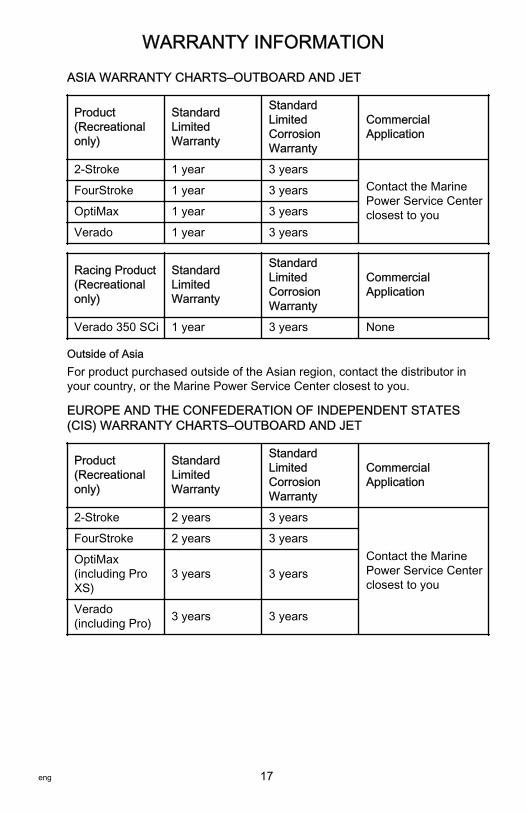
ASIA WARRANTY CHARTS–OUTBOARD AND JET
Product(Recreationalonly)
StandardLimitedWarranty
StandardLimitedCorrosionWarranty
CommercialApplication
2‑Stroke 1 year 3 yearsContact the MarinePower Service Centerclosest to you
FourStroke 1 year 3 years
OptiMax 1 year 3 years
Verado 1 year 3 years
Racing Product(Recreationalonly)
StandardLimitedWarranty
StandardLimitedCorrosionWarranty
CommercialApplication
Verado 350 SCi 1 year 3 years None
Outside of AsiaFor product purchased outside of the Asian region, contact the distributor inyour country, or the Marine Power Service Center closest to you.
EUROPE AND THE CONFEDERATION OF INDEPENDENT STATES(CIS) WARRANTY CHARTS–OUTBOARD AND JET
Product(Recreationalonly)
StandardLimitedWarranty
StandardLimitedCorrosionWarranty
CommercialApplication
2‑Stroke 2 years 3 years
Contact the MarinePower Service Centerclosest to you
FourStroke 2 years 3 years
OptiMax(including ProXS)
3 years 3 years
Verado(including Pro) 3 years 3 years

WARRANTY INFORMATION
18 eng
Racing Product(Recreationalonly)
StandardLimitedWarranty
StandardLimitedCorrosionWarranty
CommercialApplication
Verado 350 SCi 2 years 3 yearsContact the MarinePower Service Centerclosest to you
Outside Europe and CISFor products purchased outside of Europe and CIS regions, contact thedistributor in your country, or the Marine Power Service Center closest to you.
MIDDLE-EAST AND AFRICA (EXCLUDING SOUTH AFRICA)WARRANTY CHARTS–OUTBOARD AND JET
Product(Recreationalonly)
StandardLimitedWarranty
StandardLimitedCorrosionWarranty
CommercialApplication
2‑Stroke 1 year 3 years
Contact the MarinePower Service Centerclosest to you
FourStroke 2 years 3 years
OptiMax(including ProXS)
3 years 3 years
Verado(including Pro) 3 years 3 years
Racing Product(Recreational only)
Standard LimitedWarranty
Standard Limited CorrosionWarranty
Verado 350 SCi 2 years 3 years
Outside Middle‑East and AfricaFor products purchased outside of the Middle‑East and Africa regions, contactthe distributor in your country, or the Marine Power Service Center closest toyou.

WARRANTY INFORMATION
eng 19
SOUTH AFRICA WARRANTY CHARTS–OUTBOARD AND JET
Product(Recreationalonly)
StandardLimitedWarranty
StandardLimitedCorrosionWarranty
CommercialApplication
2‑Stroke 2 years 3 years
Contact the MarinePower Service Centerclosest to you
FourStroke 2 years 3 years
OptiMax(including ProXS)
3 years 3 years
Verado(including Pro) 3 years 3 years
Racing Product(Recreational only)
Standard LimitedWarranty
Standard Limited CorrosionWarranty
Verado 350 SCi 2 years 3 years
Outside South AfricaFor products purchased outside of the South Africa region, contact thedistributor in your country, or the Marine Power Service Center closest to you.

GENERAL INFORMATION
20 eng
Boater's ResponsibilitiesThe operator (driver) is responsible for the correct and safe operation of theboat and the safety of its occupants and general public. It is stronglyrecommended that each operator read and understand this entire manualbefore operating the outboard.Be sure that at least one additional person onboard is instructed in the basicsof starting and operating the outboard and boat handling in case the driver isunable to operate the boat.
Before Operating Your OutboardRead this manual carefully. Learn how to operate your outboard properly. If youhave any questions, contact your dealer.Safety and operating information that is practiced, along with using goodcommon sense, can help prevent personal injury and product damage.This manual as well as safety labels posted on the outboard use the followingsafety alerts to draw your attention to special safety instructions that should befollowed.
! DANGERIndicates a hazardous situation which, if not avoided, will result in death orserious injury.
! WARNINGIndicates a hazardous situation which, if not avoided, could result in death orserious injury.
! CAUTIONIndicates a hazardous situation which, if not avoided, could result in minor ormoderate injury.
NOTICEIndicates a situation which, if not avoided, could result in engine or majorcomponent failure.
Boat Horsepower Capacity
! WARNINGExceeding the boat's maximum horsepower rating can cause serious injuryor death. Overpowering the boat can affect boat control and flotationcharacteristics or break the transom. Do not install an engine that exceedsthe boat's maximum power rating.

GENERAL INFORMATION
eng 21
Do not overpower or overload your boat. Most boats will carry a requiredcapacity plate indicating the maximum acceptable power and load asdetermined by the manufacturer following certain federal guidelines. If in doubt,contact your dealer or the boat manufacturer.
U.S. COAST GUARD CAPACITYMAXIMUM HORSEPOWER XXXMAXIMUM PERSON CAPACITY (POUNDS) XXXMAXIMUM WEIGHT CAPACITY XXX
26777
High‑Speed and High‑Performance Boat OperationIf your outboard is to be used on a high‑speed or high‑performance boat withwhich you are unfamiliar, we recommend that you do not operate it at its highspeed capability without first requesting an initial orientation and familiarizationdemonstration ride with your dealer or an operator experienced with your boat/outboard combination. For additional information, obtain a copy of ourHi‑Performance Boat Operation booklet from your dealer, distributor, orMercury Marine.
Outboard Remote Control ModelsThe remote control connected to your outboard must be equipped with a startin neutral only protection device. This prevents the engine from starting whenthe shift is actuated in any position other than neutral.
! WARNINGStarting the engine with the drive in gear can cause serious injury or death.Never operate a boat that does not have a neutral‑safety‑protection device.
N
26838

GENERAL INFORMATION
22 eng
Propeller SelectionThe propeller on your outboard is one of the most important components in thepropulsion system. An improper propeller choice can significantly affect theperformance of your boat and could result in damage to the outboard engine.When choosing a propeller, a full selection of aluminum and stainless steelpropellers specifically designed for your outboard are available throughMercury Marine. To view the entire product offering and find the correctpropeller that is best suited for your application, visitwww.mercmarinepropellers.com or see your local authorized Mercury dealer.
SELECTING THE CORRECT PROPELLERAn accurate tachometer for measuring engine speed is important in choosingthe correct propeller.Choose a propeller for your boating application that will allow the engine tooperate within the specified full throttle operating range. When operating theboat at full throttle under normal load conditions, the engine RPM should be inthe upper half of the recommended full throttle RPM range. Refer toSpecifications. If engine RPM is above that range, select a propeller ofincreased pitch in order to reduce engine RPM. If engine RPM is below therecommended range, select a propeller of reduced pitch to increase engineRPM.IMPORTANT: To ensure proper fit, and performance, Mercury Marinerecommends the use of Mercury or Quicksilver branded propellers andmounting hardware.Propellers are designated by the diameter, pitch, number of blades, andmaterial. The diameter and pitch are stamped (cast) into the side or the end ofthe propeller hub. The first number represents the diameter of the propeller andthe second number represents the pitch. For example, 14x19 represents apropeller with a 14 inch diameter and 19 inches of pitch.
a - Diameterb - Pitch ‑ Travel during one revolution
a
b22669
GENERAL INFORMATION
eng 23
The following are some propeller basics that will help you determine the correctpropeller for your boating application.Diameter ‑ The diameter is the distance across the imaginary circle that ismade when the propeller rotates. The correct diameter for each propeller hasbeen predetermined for the design of your outboard. However, when more thanone diameter is available for the same pitch, use a larger diameter for heavyboat applications and a smaller diameter for lighter applications.Pitch ‑ The pitch is the theoretical distance, in inches, that a propeller travelsforward during one revolution. Pitch can be thought of similar to gears in a car.The lower the gear, the faster the car will accelerate, but with lower overall topspeed. Likewise, a lower pitch propeller will accelerate quickly, but top‑endspeed will be reduced. The higher the propeller pitch the faster the boat willusually go; though typically slowing acceleration.Determining the correct pitch size ‑ First, check the full throttle RPM undernormal load condition. If the full throttle RPM is within the recommended range,select a replacement or upgrade propeller with the same pitch as the currentpropeller.• Adding 1 inch of pitch will reduce the full throttle RPM by 150 to 200• Subtracting 1 inch of pitch will increase full throttle RPM by 150 to 200• Upgrading from a 3‑blade propeller to a 4‑blade propeller will generally
decrease full throttle RPM by 50 to 100IMPORTANT: Avoid damage to the engine. Never use a propeller that allowsthe engine to exceed the recommended full throttle RPM range when undernormal full throttle operation.
PROPELLER MATERIALMost propellers manufactured by Mercury Marine are made from eitheraluminum or stainless steel. Aluminum is suitable for general purpose use andis standard equipment on many new boats. Stainless steel is over five timesmore durable than aluminum and typically provides performance gains inacceleration and top end speed due to design efficiencies. Stainless steelpropellers also come in a larger variety of sizes and styles that allow you to dialin the ultimate performance for your boat.
3 BLADE VS. 4 BLADEAvailable in many sizes of both aluminum and stainless, 3 and 4‑bladepropellers have unique performance characteristics. In general, 3‑bladepropellers offer good all around performance and higher top speed than4‑blade propellers. However, 4‑blade propellers are usually faster to plane andmore efficient at cruising speeds, but lack the top end speed of a 3‑bladepropeller.

GENERAL INFORMATION
24 eng
Remote Steering NoticeThe steering link rod that connects the steering cable to the engine must befastened utilizing self‑locking nuts. These self‑locking nuts must never bereplaced with common nuts (nonlocking) as they will work loose and vibrate off,freeing the link rod to disengage.
! WARNINGImproper fasteners or improper installation procedures can result inloosening or disengagement of the steering link rod. This can cause asudden, unexpected loss of boat control, resulting in serious injury or deathdue to occupants being thrown within or out of the boat. Always use requiredcomponents and follow instructions and torque procedures.
a - Self‑locking nuts
Lanyard Stop SwitchThe purpose of a lanyard stop switch is to turn off the engine when the operatormoves far enough away from the operator's position (as in accidental ejectionfrom the operator's position) to activate the switch. Tiller handle outboards andsome remote control units are equipped with a lanyard stop switch. A lanyardstop switch can be installed as an accessory ‑ generally on the dashboard orside adjacent to the operator's position.A decal near the lanyard stop switch is a visual reminder for the operator toattach the lanyard to their personal flotation device (PFD) or wrist.
aa 27740
GENERAL INFORMATION
eng 25
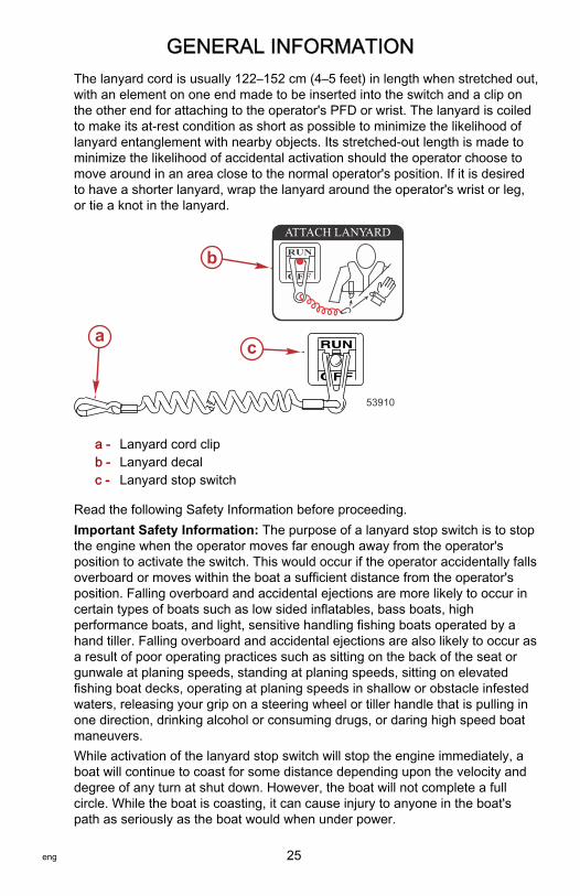
The lanyard cord is usually 122–152 cm (4–5 feet) in length when stretched out,with an element on one end made to be inserted into the switch and a clip onthe other end for attaching to the operator's PFD or wrist. The lanyard is coiledto make its at‑rest condition as short as possible to minimize the likelihood oflanyard entanglement with nearby objects. Its stretched‑out length is made tominimize the likelihood of accidental activation should the operator choose tomove around in an area close to the normal operator's position. If it is desiredto have a shorter lanyard, wrap the lanyard around the operator's wrist or leg,or tie a knot in the lanyard.
a - Lanyard cord clipb - Lanyard decalc - Lanyard stop switch
Read the following Safety Information before proceeding.Important Safety Information: The purpose of a lanyard stop switch is to stopthe engine when the operator moves far enough away from the operator'sposition to activate the switch. This would occur if the operator accidentally fallsoverboard or moves within the boat a sufficient distance from the operator'sposition. Falling overboard and accidental ejections are more likely to occur incertain types of boats such as low sided inflatables, bass boats, highperformance boats, and light, sensitive handling fishing boats operated by ahand tiller. Falling overboard and accidental ejections are also likely to occur asa result of poor operating practices such as sitting on the back of the seat orgunwale at planing speeds, standing at planing speeds, sitting on elevatedfishing boat decks, operating at planing speeds in shallow or obstacle infestedwaters, releasing your grip on a steering wheel or tiller handle that is pulling inone direction, drinking alcohol or consuming drugs, or daring high speed boatmaneuvers.While activation of the lanyard stop switch will stop the engine immediately, aboat will continue to coast for some distance depending upon the velocity anddegree of any turn at shut down. However, the boat will not complete a fullcircle. While the boat is coasting, it can cause injury to anyone in the boat'spath as seriously as the boat would when under power.
ca
b
53910
OFF
RUN
ATTACH LANYARD
GENERAL INFORMATION
26 eng
We strongly recommend that other occupants be instructed on proper startingand operating procedures should they be required to operate the engine in anemergency (if the operator is accidentally ejected).
! WARNINGIf the operator falls out of the boat, stop the engine immediately to reduce thepossibility of serious injury or death from being struck by the boat. Alwaysproperly connect the operator to the stop switch using a lanyard.
! WARNINGAvoid serious injury or death from deceleration forces resulting fromaccidental or unintended stop switch activation. The boat operator shouldnever leave the operator's station without first disconnecting the stop switchlanyard from the operator.
Accidental or unintended activation of the switch during normal operation isalso a possibility. This could cause any, or all, of the following potentiallyhazardous situations:• Occupants could be thrown forward due to unexpected loss of forward
motion ‑ a particular concern for passengers in the front of the boat whocould be ejected over the bow and possibly struck by the gearcase orpropeller.
• Loss of power and directional control in heavy seas, strong current, orhigh winds.
• Loss of control when docking.
KEEP THE LANYARD STOP SWITCH AND LANYARD CORD IN GOODOPERATING CONDITIONBefore each use, check to ensure the lanyard stop switch works properly. Startthe engine and stop it by pulling the lanyard cord. If the engine does not stop,have the switch repaired before operating the boat.Before each use, visually inspect the lanyard cord to ensure it is in goodworking condition and that there are no breaks, cuts, or wear to the cord.Check that the clips on the ends of the cord are in good condition. Replace anydamaged or worn lanyard cords.

GENERAL INFORMATION
eng 27
Protecting People in the WaterWHILE YOU ARE CRUISINGIt is very difficult for a person standing or floating in the water to take quickaction to avoid a boat heading in his/her direction, even at slow speed.
21604
Always slow down and exercise extreme caution any time you are boating in anarea where there might be people in the water.Whenever a boat is moving (coasting) and the outboard gear shift is in neutralposition, there is sufficient force by the water on the propeller to cause thepropeller to rotate. This neutral propeller rotation can cause serious injury.
WHILE THE BOAT IS STATIONARY
! WARNINGA spinning propeller, a moving boat, or any solid device attached to the boatcan cause serious injury or death to swimmers. Stop the engine immediatelywhenever anyone in the water is near your boat.
Shift the outboard into neutral and shut off the engine before allowing people toswim or be in the water near your boat.
Passenger Safety Message ‑ Pontoon Boats and Deck BoatsWhenever the boat is in motion, observe the location of all passengers. Do notallow any passengers to stand or use seats other than those designated fortraveling faster than idle speed. A sudden reduction in boat speed, such asplunging into a large wave or wake, a sudden throttle reduction, or a sharpchange of boat direction, could throw them over the front of the boat. Fallingover the front of the boat between the two pontoons will position them to be runover by the outboard.
BOATS HAVING AN OPEN FRONT DECKNo one should ever be on the deck in front of the fence while the boat is inmotion. Keep all passengers behind the front fence or enclosure.

GENERAL INFORMATION
28 eng
Persons on the front deck could easily be thrown overboard or personsdangling their feet over the front edge could get their legs caught by a waveand pulled into the water.
26782
! WARNINGSitting or standing in an area of the boat not designed for passengers atspeeds above idle can cause serious injury or death. Stay back from the frontend of deck boats or raised platforms and remain seated while the boat is inmotion.
BOATS WITH FRONT MOUNTED, RAISED PEDESTAL FISHING SEATSElevated fishing seats are not intended for use when the boat is traveling fasterthan idle or trolling speed. Sit only in seats designated for traveling at fasterspeeds.Any unexpected, sudden reduction in boat speed could result in the elevatedpassenger falling over the front of the boat.
26783

GENERAL INFORMATION
eng 29
Wave and Wake JumpingOperating recreational boats over waves and wake is a natural part of boating.However, when this activity is done with sufficient speed to force the boat hullpartially or completely out of the water, certain hazards arise, particularly whenthe boat enters the water.
26784
The primary concern is the boat changing direction while in the midst of thejump. In such case, the landing may cause the boat to veer violently in a newdirection. Such a sharp change in direction can cause occupants to be thrownout of their seats, or out of the boat.
! WARNINGWave or wake jumping can cause serious injury or death from occupantsbeing thrown within or out of the boat. Avoid wave or wake jumping wheneverpossible.
There is another less common hazardous result from allowing your boat tolaunch off a wave or wake. If the bow of your boat pitches down far enoughwhile airborne, upon water contact it may penetrate under the water surfaceand submarine for an instant. This will bring the boat to a nearly instantaneousstop and can send the occupants flying forward. The boat may also steersharply to one side.
GENERAL INFORMATION
30 eng
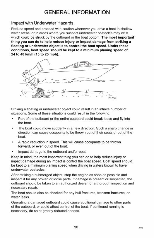
Impact with Underwater HazardsReduce speed and proceed with caution whenever you drive a boat in shallowwater areas, or in areas where you suspect underwater obstacles may existwhich could be struck by the outboard or the boat bottom. The most importantthing you can do to help reduce injury or impact damage from striking afloating or underwater object is to control the boat speed. Under theseconditions, boat speed should be kept to a minimum planing speed of24 to 40 km/h (15 to 25 mph).
26785
Striking a floating or underwater object could result in an infinite number ofsituations. Some of these situations could result in the following:• Part of the outboard or the entire outboard could break loose and fly into
the boat.• The boat could move suddenly in a new direction. Such a sharp change in
direction can cause occupants to be thrown out of their seats or out of theboat.
• A rapid reduction in speed. This will cause occupants to be thrownforward, or even out of the boat.
• Impact damage to the outboard and/or boat.Keep in mind, the most important thing you can do to help reduce injury orimpact damage during an impact is control the boat speed. Boat speed shouldbe kept to a minimum planing speed when driving in waters known to haveunderwater obstacles.After striking a submerged object, stop the engine as soon as possible andinspect it for any broken or loose parts. If damage is present or suspected, theoutboard should be taken to an authorized dealer for a thorough inspection andnecessary repair.The boat should also be checked for any hull fractures, transom fractures, orwater leaks.Operating a damaged outboard could cause additional damage to other partsof the outboard, or could affect control of the boat. If continued running isnecessary, do so at greatly reduced speeds.
GENERAL INFORMATION
eng 31
! WARNINGOperating a boat or engine with impact damage can result in productdamage, serious injury, or death. If the vessel experiences any form ofimpact, have an authorized Mercury Marine dealer inspect and repair thevessel or power package.
Exhaust EmissionsBE ALERT TO CARBON MONOXIDE POISONINGCarbon monoxide (CO) is a deadly gas that is present in the exhaust fumes ofall internal combustion engines, including the engines that propel boats, andthe generators that power boat accessories. By itself, CO is odorless, colorless,and tasteless, but if you can smell or taste engine exhaust, you are inhalingCO.Early symptoms of carbon monoxide poisoning, which are similar to thesymptoms of seasickness and intoxication, include headache, dizziness,drowsiness, and nausea.
! WARNINGInhaling engine exhaust gases can result in carbon monoxide poisoning,which can lead to unconsciousness, brain damage, or death. Avoid exposureto carbon monoxide.Stay clear from exhaust areas when engine is running. Keep the boatwell‑ventilated while at rest or underway.
STAY CLEAR OF EXHAUST AREAS
41127
Engine exhaust gases contain harmful carbon monoxide. Avoid areas ofconcentrated engine exhaust gases. When engines are running, keepswimmers away from the boat, and do not sit, lie, or stand on swim platforms orboarding ladders. While underway, do not allow passengers to be positionedimmediately behind the boat (platform dragging, teak/body surfing). Thisdangerous practice not only places a person in an area of high engine exhaustconcentration, but also subjects them to the possibility of injury from the boatpropeller.

GENERAL INFORMATION
32 eng
GOOD VENTILATIONVentilate the passenger area, open side curtains or forward hatches to removefumes.Example of desired air flow through the boat:
21622
POOR VENTILATIONUnder certain running and/or wind conditions, permanently enclosed or canvasenclosed cabins or cockpits with insufficient ventilation may draw in carbonmonoxide. Install one or more carbon monoxide detectors in your boat.Although the occurrence is rare, on a very calm day, swimmers andpassengers in an open area of a stationary boat that contains, or is near, arunning engine may be exposed to a hazardous level of carbon monoxide.1. Examples of poor ventilation while the boat is stationary:
a - Operating the engine when the boat is moored in a confined spaceb - Mooring close to another boat that has its engine operating
2. Examples of poor ventilation while the boat is moving:
a - Operating the boat with the trim angle of the bow too highb - Operating the boat with no forward hatches open (station wagon effect)
21626
ab
a b
21628

GENERAL INFORMATION
eng 33
Selecting Accessories for Your OutboardGenuine Mercury Precision or Quicksilver Accessories have been specificallydesigned and tested for your outboard. These accessories are available fromMercury Marine dealers.IMPORTANT: Check with your dealer before installing accessories. The misuseof approved accessories or the use of nonapproved accessories can damagethe product.Some accessories not manufactured or sold by Mercury Marine are notdesigned to be safely used with your outboard or outboard operating system.Read the installation, operation and maintenance manuals for all your selectedaccessories.Refer to Outboard Installation ‑ Accessories Mounted to the TransomClamp Bracket for important information on mounting accessories to thetransom clamp bracket.
Safe Boating RecommendationsTo safely enjoy the waterways, familiarize yourself with local and all othergovernmental boating regulations and restrictions and consider the followingsuggestions.Know and obey all nautical rules and laws of the waterways.• We recommend that all powerboat operators complete a boating safety
course. In the U.S., the U.S. Coast Guard Auxiliary, the Power Squadron,the Red Cross, and your state or provincial boating law enforcementagency provide courses. For more information in the U.S., call the BoatU.S. Foundation at 1‑800‑336‑BOAT (2628).
Perform safety checks and required maintenance.• Follow a regular schedule and ensure that all repairs are properly made.Check safety equipment onboard.• Here are some suggestions of the types of safety equipment to carry
when boating:Approved fire extinguishers
Signal devices: flashlight, rockets or flares, flag, and whistle or horn
Tools necessary for minor repairs
Anchor and extra anchor line
Manual bilge pump and extra drain plugs
Drinking water
Radio
Paddle or oar
Spare propeller, thrust hubs, and an appropriate wrench
GENERAL INFORMATION
34 eng
First aid kit and instructions
Waterproof storage containers
Spare operating equipment, batteries, bulbs, and fuses
Compass and map or chart of the area
Personal flotation device (one per person onboard)
Watch for signs of weather change and avoid foul weather and rough‑seaboating.Tell someone where you are going and when you expect to return.Passenger boarding.• Stop the engine whenever passengers are boarding, unloading, or are
near the back (stern) of the boat. Shifting the drive unit into neutral is notsufficient.
Use personal flotation devices.• Federal law requires that there be a U.S. Coast Guard‑approved life
jacket (personal flotation device), correctly sized and readily accessiblefor every person onboard, plus a throwable cushion or ring. We stronglyadvise that everyone wear a life jacket at all times while in the boat.
Prepare other boat operators.• Instruct at least one person onboard in the basics of starting and
operating the engine and boat handling in case the driver becomesdisabled or falls overboard.
Do not overload your boat.• Most boats are rated and certified for maximum load (weight) capacities
(refer to your boat's capacity plate). Know your boat's operating andloading limitations. Know if your boat will float if it is full of water. When indoubt, contact your authorized Mercury Marine dealer or the boatmanufacturer.
Ensure that everyone in the boat is properly seated.• Do not allow anyone to sit or ride on any part of the boat that was not
intended for such use. This includes the backs of seats, gunwales,transom, bow, decks, raised fishing seats, and any rotating fishing seat.Passengers should not sit or ride anywhere that sudden unexpectedacceleration, sudden stopping, unexpected loss of boat control, or suddenboat movement could cause a person to be thrown overboard or into theboat. Ensure that all passengers have a proper seat and are in it beforeany boat movement.
Never operate a boat while under the influence of alcohol or drugs. It isthe law.• Alcohol or drugs can impair your judgment and greatly reduce your ability
to react quickly.Know your boating area and avoid hazardous locations.

GENERAL INFORMATION
eng 35
Be alert.• The operator of the boat is responsible by law to maintain a proper
lookout by sight and hearing. The operator must have an unobstructedview particularly to the front. No passengers, load, or fishing seats shouldblock the operator's view when the boat is above idle or planing transitionspeed. Watch out for others, the water, and your wake.
Never drive your boat directly behind a water skier.• Your boat traveling at 40 km/h (25 mph) will overtake a fallen skier who is
61 m (200 ft) in front of you in five seconds.Watch fallen skiers.• When using your boat for waterskiing or similar activities, always keep a
fallen or down skier on the operator's side of the boat while returning toattend to the skier. The operator should always have the down skier insight and never back up to the skier or anyone in the water.
Report accidents.• Boat operators are required by law to file a boating accident report with
their state boating law enforcement agency when their boat is involved incertain boating accidents. A boating accident must be reported if 1) thereis loss of life or probable loss of life, 2) there is personal injury requiringmedical treatment beyond first aid, 3) there is damage to boats or otherproperty where the damage value exceeds $500.00, or 4) there iscomplete loss of the boat. Seek further assistance from local lawenforcement.
Recording Serial NumberIt is important to record this number for future reference. The serial number islocated on the outboard as shown.
a - Serial numberb - Model designationc - Year manufacturedd - Certified Europe Insignia (as applicable)
HPLB
23884
- - - . - - -
XXXXXXX-
XXXXX XXXL
Me rc ury Marine
Serial Number
Brunswick Corp. Made in Japan
XX
XXXX XXXHP XXXLB XXX KG XXX
KW XXX
Model Number b
c
a
d
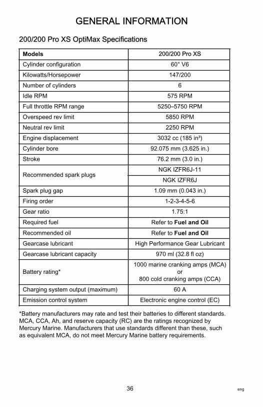
GENERAL INFORMATION
36 eng
200/200 Pro XS OptiMax Specifications
Models 200/200 Pro XS
Cylinder configuration 60° V6
Kilowatts/Horsepower 147/200
Number of cylinders 6
Idle RPM 575 RPM
Full throttle RPM range 5250–5750 RPM
Overspeed rev limit 5850 RPM
Neutral rev limit 2250 RPM
Engine displacement 3032 cc (185 in³)
Cylinder bore 92.075 mm (3.625 in.)
Stroke 76.2 mm (3.0 in.)
Recommended spark plugsNGK IZFR6J‑11
NGK IZFR6J
Spark plug gap 1.09 mm (0.043 in.)
Firing order 1‑2‑3‑4‑5‑6
Gear ratio 1.75:1
Required fuel Refer to Fuel and Oil
Recommended oil Refer to Fuel and Oil
Gearcase lubricant High Performance Gear Lubricant
Gearcase lubricant capacity 970 ml (32.8 fl oz)
Battery rating*1000 marine cranking amps (MCA)
or800 cold cranking amps (CCA)
Charging system output (maximum) 60 A
Emission control system Electronic engine control (EC)
*Battery manufacturers may rate and test their batteries to different standards.MCA, CCA, Ah, and reserve capacity (RC) are the ratings recognized byMercury Marine. Manufacturers that use standards different than these, suchas equivalent MCA, do not meet Mercury Marine battery requirements.

GENERAL INFORMATION
eng 37
225/250 Pro XS Specifications
Models 225 250
Cylinder configuration 60° V6 60° V6
Propeller shaft horsepower 225 250
Propeller shaft kilowatts 165 184
Number of cylinders 6
Idle RPM 575 RPM
Full throttle RPM range 5500–6000 RPM
Overspeed Rev Limit 6300 RPM
Neutral Rev Limit 2250 RPM
Engine displacement 3032 cc (185 in³)
Cylinder bore 92.075 mm (3.625 in.)
Stroke 76.2 mm (3.0 in.)
Recommended spark plugsNGK IZFR6J‑11
NGK IZFR6J
Spark plug gap 1.09 mm (0.043 in.)
Firing order 1‑2‑3‑4‑5‑6
Gear ratio 1.75:1
Required fuel Refer to Fuel and Oil
Recommended oil Refer to Fuel and Oil
Gearcase lubricant High Performance Gear Lubricant
Gearcaselubricant capacity
Standardgearcase 970 ml (32.8 fl oz)
Gen II TorqueMaster 1040 ml (35.1 fl oz)
Battery rating1000 marine cranking amps (MCA)
or800 cold cranking amps (CCA)1.
Charging system output (maximum) 60 A
Emission control system Electronic engine control (EC)
1. Battery manufacturers may rate and test their batteries to different standards. Consult with the specific batterymanufacturer for comparison ratings.

GENERAL INFORMATION
38 eng
250 OptiMax Specifications
Models 250
Cylinder configuration 60° V6
Kilowatts/horsepower 184/250
Number of cylinders 6
Idle RPM 575 RPM
Full throttle RPM range 5500–6000 RPM
Overspeed rev limit 6300 RPM
Neutral rev limit 2250 RPM
Engine displacement 3032 cc (185 in³)
Cylinder bore 92.075 mm (3.625 in.)
Stroke 76.2 mm (3.0 in.)
Recommended spark plugsNGK IZFR6J‑11
NGK IZFR6J
Spark plug gap 1.09 mm (0.043 in.)
Firing order 1‑2‑3‑4‑5‑6
Gear ratio 1.75:1
Required fuel Refer to Fuel and Oil
Recommended oil Refer to Fuel and Oil
Gearcase lubricant High Performance Gear Lubricant
Gearcase lubricant capacity 970 ml (32.8 fl oz)
Battery rating*1000 marine cranking amps (MCA)
or800 cold cranking amps (CCA)
Charging system output (maximum) 60 A
Emission control system Electronic engine control (EC)
*Battery manufacturers may rate and test their batteries to different standards.MCA, CCA, Ah, and reserve capacity (RC) are the ratings recognized byMercury Marine. Manufacturers that use standards different than these, suchas equivalent MCA, do not meet Mercury Marine battery requirements.

GENERAL INFORMATION
eng 39
Component Identification
1 - Top cowl2 - Front cowl latch3 - Auxiliary tilt switch4 - Clamp/swivel bracket5 - Gearcase6 - Cooling water intake7 - Skeg8 - Anti‑ventilation plate9 - Anodes (one per
side)10 - Driveshaft housing11 - Bottom cowl12 - Water pump indicator
(tell‑tale)13 - Side cowl latches
(both sides)
1
2
4
56
7
8
9
1011
12
13
3
51577

TRANSPORTING
40 eng
Trailering Boat/OutboardTrailer your boat with the outboard tilted down in a vertical operating position.If additional ground clearance is required, the outboard should be tilted upusing an accessory outboard support device. Refer to your local dealer forrecommendations. Additional clearance may be required for railroad crossings,driveways and trailer bouncing.
28284
IMPORTANT: Do not rely on the power trim/tilt system or tilt support lever tomaintain proper ground clearance for trailering. The outboard tilt support leveris not intended to support the outboard for trailering.Shift the outboard to forward gear. This prevents the propeller from spinningfreely.
FUEL AND OIL
eng 41
Fuel RecommendationsIMPORTANT: Use of improper gasoline can damage your engine. Enginedamage resulting from the use of improper gasoline is considered misuseof the engine, and damage caused thereby will not be covered under thelimited warranty.
FUEL RATINGSMercury Marine engines will operate satisfactorily when using a major brand ofunleaded gasoline meeting the following specifications:USA and Canada ‑ having a posted pump octane rating of 87 (R+M)/2minimum. Premium gasoline (92 [R+M]/2 octane) is also acceptable. Do notuse leaded gasoline.Outside USA and Canada ‑ having a posted pump octane rating of 90 RONminimum. Premium gasoline (98 RON) is also acceptable. If unleaded gasolineis not available, use a major brand of leaded gasoline.
USING REFORMULATED (OXYGENATED) GASOLINES (USA ONLY)This type of gasoline is required in certain areas of the USA. The two types ofoxygenates used in these fuels are alcohol (ethanol) or ether (MTBE or ETBE).If ethanol is the oxygenate that is used in the gasoline in your area, refer toGasolines Containing Alcohol.These reformulated gasolines are acceptable for use in your Mercury Marineengine.
GASOLINES CONTAINING ALCOHOLIf the gasoline in your area contains either methanol (methyl alcohol) or ethanol(ethyl alcohol), you should be aware of certain adverse effects that can occur.These adverse effects are more severe with methanol. Increasing thepercentage of alcohol in the fuel can also worsen these adverse effects.Some of these adverse effects are caused because the alcohol in the gasolinecan absorb moisture from the air, resulting in a separation of the water/alcoholfrom the gasoline in the fuel tank.The fuel system components on your Mercury Marine engine will withstand upto 10% alcohol content in the gasoline. We do not know what percentage yourboat's fuel system will withstand. Contact your boat manufacturer for specificrecommendations on the boat's fuel system components (fuel tanks, fuel lines,and fittings). Be aware that gasolines containing alcohol may cause increased:• Corrosion of metal parts• Deterioration of rubber or plastic parts• Fuel permeation through rubber fuel lines• Starting and operating difficulties

FUEL AND OIL
42 eng
! WARNINGFuel leakage is a fire or explosion hazard, which can cause serious injury ordeath. Periodically inspect all fuel system components for leaks, softening,hardening, swelling, or corrosion, particularly after storage. Any sign ofleakage or deterioration requires replacement before further engineoperation.
Because of possible adverse effects of alcohol in gasoline, it is recommendedthat only alcohol‑free gasoline be used where possible. If only fuel containingalcohol is available, or if the presence of alcohol is unknown, increasedinspection frequency for leaks and abnormalities is required.IMPORTANT: When operating a Mercury Marine engine on gasoline containingalcohol, storage of gasoline in the fuel tank for long periods should be avoided.Long periods of storage, common to boats, create unique problems. In cars,alcohol‑blend fuels normally are consumed before they can absorb enoughmoisture to cause trouble, but boats often sit idle long enough for phaseseparation to take place. In addition, internal corrosion may take place duringstorage if alcohol has washed protective oil films from internal components.
Oil Recommendation
Recommended Oil OptiMax Oil or Premium Plus 2‑Cycle TCW 3Outboard Oil
Mercury OptiMax/DFI or Quicksilver DFI 2‑Cycle Engine Oil is recommendedfor your engine. If Mercury OptiMax/DFI or Quicksilver DFI 2‑Cycle Engine Oilis not available, we recommend using Mercury or Quicksilver TC‑W3 PremiumPlus 2‑Cycle Oil. Severe engine damage may result from use of an inferior oil.Mercury Racing 2‑Stroke Oil is recommended for OptiMax engines that areused in applications of extreme loads associated with commercial, work, orextended periods of high RPM. The added lubrication and protection propertieswith Mercury Racing 2‑Stroke oil, maximizes engine horsepower whileprotecting against heat, reduces wear and carbon deposit build‑up.
Fuel AdditivesTo minimize carbon deposit buildup in the engine, it is recommended to addMercury or Quicksilver Quickstor fuel stabilizer additive to the engine's fuel ateach tank fill throughout the boating season. Use additive as directed oncontainer.
Fuel RequirementsDo not use premixed gas and oil in this engine. The engine automaticallyreceives extra oil during engine break‑in. Use a fresh supply of therecommended gasoline during engine break‑in and after engine break‑in.
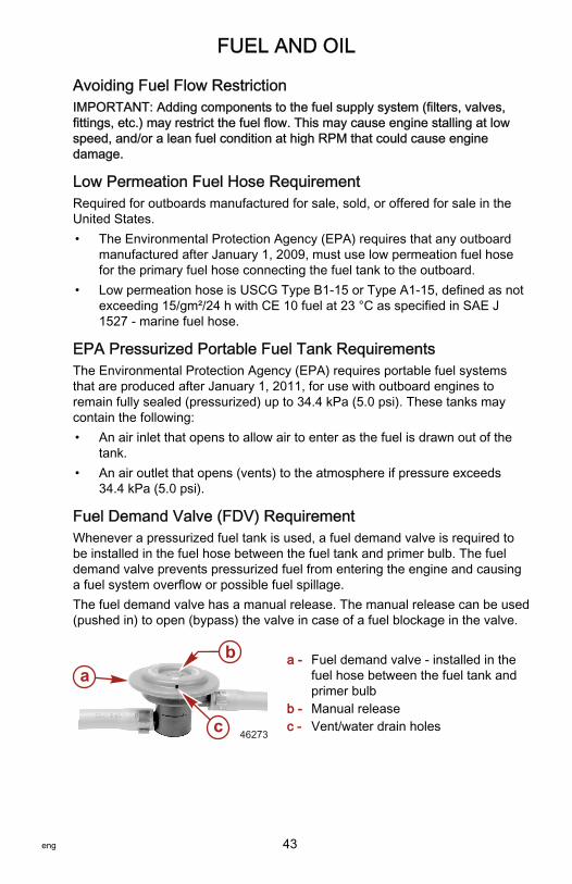
FUEL AND OIL
eng 43
Avoiding Fuel Flow RestrictionIMPORTANT: Adding components to the fuel supply system (filters, valves,fittings, etc.) may restrict the fuel flow. This may cause engine stalling at lowspeed, and/or a lean fuel condition at high RPM that could cause enginedamage.
Low Permeation Fuel Hose RequirementRequired for outboards manufactured for sale, sold, or offered for sale in theUnited States.• The Environmental Protection Agency (EPA) requires that any outboard
manufactured after January 1, 2009, must use low permeation fuel hosefor the primary fuel hose connecting the fuel tank to the outboard.
• Low permeation hose is USCG Type B1‑15 or Type A1‑15, defined as notexceeding 15/gm²/24 h with CE 10 fuel at 23 °C as specified in SAE J1527 ‑ marine fuel hose.
EPA Pressurized Portable Fuel Tank RequirementsThe Environmental Protection Agency (EPA) requires portable fuel systemsthat are produced after January 1, 2011, for use with outboard engines toremain fully sealed (pressurized) up to 34.4 kPa (5.0 psi). These tanks maycontain the following:• An air inlet that opens to allow air to enter as the fuel is drawn out of the
tank.• An air outlet that opens (vents) to the atmosphere if pressure exceeds
34.4 kPa (5.0 psi).
Fuel Demand Valve (FDV) RequirementWhenever a pressurized fuel tank is used, a fuel demand valve is required tobe installed in the fuel hose between the fuel tank and primer bulb. The fueldemand valve prevents pressurized fuel from entering the engine and causinga fuel system overflow or possible fuel spillage.The fuel demand valve has a manual release. The manual release can be used(pushed in) to open (bypass) the valve in case of a fuel blockage in the valve.
a - Fuel demand valve ‑ installed in thefuel hose between the fuel tank andprimer bulb
b - Manual releasec - Vent/water drain holes
a
c
b
46273

FUEL AND OIL
44 eng
Mercury Marine's Pressurized Portable Fuel TankMercury Marine has created a new portable pressurized fuel tank that meetsthe preceding EPA requirements. These fuel tanks are available as anaccessory or are provided with certain portable outboard models.
SPECIAL FEATURES OF THE PORTABLE FUEL TANK• The fuel tank has a two‑way valve which allows air to enter the tank as
the fuel is drawn to the engine, and also opens to vent to the atmosphereif internal pressure in the tank exceeds 34.4 kPa (5.0 psi). A hissing noisemay be heard as the tank vents to the atmosphere. This is normal.
• The fuel tank includes a fuel demand valve that prevents pressurized fuelfrom entering the engine and causing a fuel system overflow or possiblefuel spillage.
• When installing the fuel tank cap, turn the cap to the right until you hear aclick. This signals that the fuel cap is fully seated. A built‑in deviceprevents overtightening.
• The fuel tank has a manual vent screw which should be closed fortransportation and open for operation and cap removal.
Since sealed fuel tanks are not vented, they will expand and contract as thefuel expands and contracts during heating and cooling cycles of the outside air.This is normal.
REMOVING THE FUEL CAP
a - Fuel capb - Manual vent screwc - Tab lock
IMPORTANT: Contents may be under pressure. Rotate the fuel cap 1/4 turn torelieve pressure before opening.1. Open the manual vent screw on top of the fuel cap.2. Turn the fuel cap until it contacts the tab lock.3. Press down on the tab lock. Rotate the fuel cap 1/4 turn to relieve the
pressure.4. Press down on the tab lock again and remove the cap.
DIRECTIONS FOR USING THE PRESSURIZED PORTABLE FUEL TANK1. When installing the fuel tank cap, turn the cap to the right until you hear a
click. This signals that the fuel cap is fully seated. A built‑in deviceprevents overtightening.
ab
c46290

FUEL AND OIL
eng 45
2. Open the manual vent screw on top of the cap for operation and capremoval. Close the manual vent screw for transportation.
3. For fuel hoses that have quick disconnects, disconnect the fuel line fromthe engine or fuel tank when not in use.
4. Follow Filling Fuel Tank instructions for fueling.
Filling Remote Oil TankRemove the filler cap and fill with the specified oil. Oil tank capacity is11.5 liters (3 gallons). Replace the filler cap and tighten securely.IMPORTANT: Always make sure the oil tank caps are threaded on tight. An airleak will prevent oil flow to the engine.
2723
Filling Engine Mounted Oil Reservoir TankNOTE: Filling this tank is only necessary if the oil level should ever drop andthe low oil warning system is activated.1. Remove the top cowl.2. Loosen the fill cap on the engine oil reservoir tank. Run the engine until all
the air has been vented out of the oil reservoir tank and tank is filled withoil to the point of overflow.
3. Tighten the fill cap. Stop the engine and replace the top cowl.
29424

FUEL AND OIL
46 eng
Filling Fuel Tank
! WARNINGAvoid serious injury or death from a gasoline fire or explosion. Use cautionwhen filling fuel tanks. Always stop the engine and do not smoke or allowopen flames or sparks in the area while filling fuel tanks.
Fill the fuel tanks outdoors away from heat, sparks, and open flames.Remove the portable fuel tanks from the boat to refill them.Always stop the engine before filling the tanks.Do not completely fill the fuel tanks. Leave approximately 10% of the tankvolume unfilled. Fuel will expand in volume as its temperature rises and canleak under pressure if the tank is completely filled.

FEATURES AND CONTROLS
eng 47
Remote Control FeaturesYour boat may be equipped with one of the Mercury Precision or Quicksilverremote controls shown. If not, consult your dealer for a description of thefunctions and operations of the remote control.
a - Control handle – forward, neutral, reverseb - Neutral release leverc - Trim/tilt switch (if equipped) – Refer to Features and Controls –
Power Trim and Tiltd - Lanyard stop switch – Refer to General Information – Lanyard Stop
Switche - Lanyard – Refer to General Information – Lanyard Stop Switchf - Throttle friction adjustment – Console controls require cover removal for
adjustmentg - Ignition key switch – "OFF," "ON," START"h - Fast idle lever – Refer to Operation – Starting the Enginei - Throttle only button – Refer to Operation – Starting the Engine
Warning System
WARNING HORN SIGNALSWhen the key switch is turned to the "ON" position, the horn will turn on for amoment as a test to indicate the horn is working.There are two types of warning horns to alert the operator of an active problemwithin the engine’s operating system.
fa
c
de
b h
ca
g
d
e
b
i
f
g
i
c
a
f26800

FEATURES AND CONTROLS
48 eng
1. Continuous six second beep: Indicates a critical engine condition.Depending on the condition, the Engine Guardian system may engageand protect the engine by limiting power. You should return to portimmediately and contact your servicing dealer.
2. Intermittent short beeps for six seconds: Indicates a noncritical enginecondition. This condition does not require immediate attention. You maycontinue using your boat, however, depending on the nature of theproblem, the engine’s power may be limited by the Engine Guardiansystem (see Engine Guardian System following) to protect the engine.You should contact your servicing dealer at your earliest convenience.
It is important to note that in either of the above scenarios, the horn will onlysound one time. If you key the engine off and restart it, the horn will soundagain, one time, if the fault is still present. For visual display of the specificengine functions and additional engine data, refer to SmartCraft Productinformation, following.A few of the noncritical conditions indicated by the intermittent short beeps forsix seconds can be corrected by the operator. These operator correctableconditions are as follows:• Water in the engine mounted fuel filter. Refer to Maintenance – Water
Separating Fuel Filter.• Cooling system (water pressure or engine temperature) problem. Stop the
engine and check the water intake holes in the lower unit for obstruction.• Low engine oil level. Refer to Fuel and Oil – Checking and Adding
Engine Oil.
ENGINE GUARDIAN SYSTEMThe Engine Guardian system monitors the critical sensors on the engine forany early indications of problems. Engine Guardian is functional whenever yourengine is operating, so you never have to be concerned about whether or notyou are protected. The system will respond to a problem by sounding thewarning horn for six seconds and/or reducing engine power in order to provideengine protection.If Engine Guardian has been activated, reduce the engine speed. The problemwill need to be identified and corrected. The system must be reset before theengine will operate at higher speeds. Moving the throttle lever back to the idleposition will reset the Engine Guardian system. If the Engine Guardian systemhas determined the reset has not corrected the problem, Engine Guardian willremain activated, limiting the throttle. The problem must be identified andcorrected before Engine Guardian will allow the engine to reach a normaloperating RPM.

FEATURES AND CONTROLS
eng 49
OVERSPEED REV LIMITThe overspeed rev limit is set at an RPM greater than the operating range. Inthe event that the engine is operated at an RPM greater than or equal to theoverspeed limit, the PCM does not allow the engine to maintain the powerrequested by the operator. Refer to Specifications to determine this engine’sRPM limit.Upon reaching the beginning of the rev limit, Engine Guardian will cut‑out theignition to specific cylinders. If the operator does not reduce engine speed,Engine Guardian will cut‑out the ignition to all the cylinders. There is no audiblewarning while Engine Guardian overspeed limit is active.To reset the Engine Guardian protection:1. Completely reduce the throttle for three seconds.2. Engage the throttle. If the engine does not respond, repeat step one.
SMARTCRAFT PRODUCTA Mercury SmartCraft System instrument package can be purchased for thisoutboard. A few of the functions the instrument package will display are engineRPM, coolant temperature, oil pressure, water pressure, battery voltage, fuelconsumption, and engine operating hours.The SmartCraft instrument package will also aid in Engine Guardiandiagnostics. The SmartCraft Instrument package will display critical enginealarm data and potential problems.

FEATURES AND CONTROLS
50 eng
Power Trim and TiltYour outboard has a trim/tilt control called power trim. This enables theoperator to easily adjust the position of the outboard by pressing the trimswitch. Moving the outboard in closer to the boat transom is called trimming inor down. Moving the outboard further away from the boat transom is calledtrimming out or up. The term trim generally refers to the adjustment of theoutboard within the first 20° range of travel. This is the range used whileoperating your boat on plane. The term tilt is generally used when referring toadjusting the outboard further up out of the water. With the engine turned off,the outboard can be tilted out of the water. At low idle speed, the outboard canalso be tilted up past the trim range to permit, for example, shallow wateroperation.
a - Trim switchb - Tilt range of travelc - Trim range of travel
POWER TRIM OPERATIONWith most boats, operating around the middle of the trim range will givesatisfactory results. However, to take full advantage of the trimming capabilitythere may be times when you choose to trim your outboard all the way in orout. Along with an improvement in some performance aspects comes a greaterresponsibility for the operator, and this is being aware of some potential controlhazards.The most significant control hazard is a pull or torque that can be felt on thesteering wheel or tiller handle. This steering torque results from the outboardbeing trimmed so the propeller shaft is not parallel to the water surface.
a
bc 28295

FEATURES AND CONTROLS
eng 51
! WARNINGTrimming the outboard beyond a neutral steering condition may result in apull on the steering wheel or tiller handle and loss of boat control. Maintaincontrol of the boat if trimming beyond a neutral steering condition.
Consider the following lists carefully.1. Trimming in or down can:
• Lower the bow.• Result in quicker planing off, especially with a heavy load or a stern
heavy boat.• Generally improve the ride in choppy water.• Increase steering torque or pull to the right (with the normal right‑hand
rotation propeller.)• In excess, can lower the bow of some boats to a point where they
begin to plow with their bow in the water while on plane. This canresult in an unexpected turn in either direction (called bow steering oroversteering) if any turn is attempted, or if a significant wave isencountered.
! WARNINGOperating the boat at high speeds with the outboard trimmed too far undercan create excessive bow steer, resulting in the operator losing control ofthe boat. Install the trim limit pin in a position that prevents excessive trimunder and operate the boat in a safe manner.
• In rare circumstances, the owner may decide to limit the trim in. Thiscan be accomplished by purchasing a stainless steel tilt pin from yourdealer and inserting it in whatever adjustment hole in the transombrackets is desired. The nonstainless steel shipping bolt should not beused in this application other than on a temporary basis.
2. Trimming out or up can:• Lift the bow higher out of the water.• Generally increase top speed.• Increase clearance over submerged objects or a shallow bottom.• Increase steering torque or pull to the left at a normal installation
height (with the normal right‑hand rotation propeller.)• In excess, can cause boat porpoising (bouncing) or propeller
ventilation.• Cause engine overheating if any cooling water intake holes are above
the waterline.

FEATURES AND CONTROLS
52 eng
TILTING OPERATIONTo tilt the outboard, shut off the engine and press the trim/tilt switch or auxiliarytilt switch to the up position. The outboard will tilt up until the switch is releasedor it reaches its maximum tilt position.1. Engage the tilt support lever by rotating the knob to bring the support
lever upward.2. Lower the outboard to rest on the tilt support lever.3. Disengage the tilt support lever by raising the outboard off the support
lever and rotating the lever down. Lower the outboard.
a - Tilt support leverb - Knob
MANUAL TILTINGIf the outboard cannot be tilted using the power trim/tilt switch, the outboard canbe manually tilted.NOTE: The manual tilt release valve must be tightened before operating theoutboard to prevent the outboard from tilting up during reverse operation.Turn out the manual tilt release valve three turns counterclockwise. This allowsmanual tilting of the outboard. Tilt the outboard to the desired position andtighten the manual tilt release valve.
22362
SHALLOW WATER OPERATIONWhen operating your boat in shallow water, you can tilt the outboard beyondthe maximum trim range to prevent hitting bottom.1. Reduce the engine speed below 2000 RPM.2. Tilt the outboard up. Make sure all the water intake holes stay submerged
at all times.
b
a
27778

FEATURES AND CONTROLS
eng 53
3. Operate the engine at slow speed only. If engine speed exceeds 2000RPM, the outboard will automatically return down to the maximum trimrange.
AUXILIARY TILT SWITCHThis switch can be used to tilt the outboard up or down using the power trimsystem.
a - Auxiliary tilt switch
a
2745
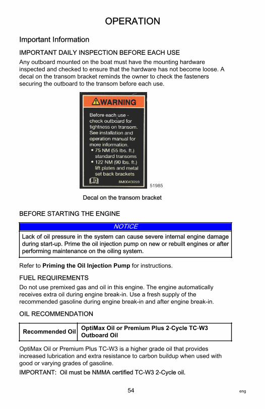
OPERATION
54 eng
Important Information
IMPORTANT DAILY INSPECTION BEFORE EACH USEAny outboard mounted on the boat must have the mounting hardwareinspected and checked to ensure that the hardware has not become loose. Adecal on the transom bracket reminds the owner to check the fastenerssecuring the outboard to the transom before each use.
51985
Decal on the transom bracket
BEFORE STARTING THE ENGINE
NOTICELack of oil pressure in the system can cause severe internal engine damageduring start‑up. Prime the oil injection pump on new or rebuilt engines or afterperforming maintenance on the oiling system.
Refer to Priming the Oil Injection Pump for instructions.
FUEL REQUIREMENTSDo not use premixed gas and oil in this engine. The engine automaticallyreceives extra oil during engine break‑in. Use a fresh supply of therecommended gasoline during engine break‑in and after engine break‑in.
OIL RECOMMENDATION
Recommended Oil OptiMax Oil or Premium Plus 2‑Cycle TC‑W3Outboard Oil
OptiMax Oil or Premium Plus TC‑W3 is a higher grade oil that providesincreased lubrication and extra resistance to carbon buildup when used withgood or varying grades of gasoline.IMPORTANT: Oil must be NMMA certified TC‑W3 2‑Cycle oil.

OPERATION
eng 55
Periodically consult with your dealer to get the latest gasoline and oilrecommendations. If Mercury Precision or Quicksilver 2‑Cycle Outboard Oil isnot available, substitute another brand of 2‑Cycle outboard oil that is NMMACertified TC‑W3. The use of an inferior 2‑Cycle outboard oil can reduce enginedurability. Damage from use of inferior oil may not be covered under the limitedwarranty.
Engine Break‑inIMPORTANT: Failure to follow the engine break‑in procedures can result inpoor performance throughout the life of the engine and can cause enginedamage. Always follow break‑in procedures.
Break‑in Procedure
Vary throttle settings during break‑in. Use the following suggestions.
First Hour• Allow the engine to warm‑up for 30–60 seconds.
• Do not idle for more than five minutes.
• Run the engine the majority of the time between 4000–5400 RPM(approximately three‑quarter throttle).
• Short bursts of wide‑open throttle for 10 seconds or less are acceptable.
• Change the engine speed approximately every two minutes.
• Avoid trimming the outboard out (up) beyond a vertical trim positionduring operation.
• Avoid using a hydraulic jack plate to raise the engine during the break‑incycle.
Next Three Hours: Change the engine speed every 10 minutes.
Engine Break‑in Fuel MixtureThe propulsion control module (PCM) controls oil and fuel mixture duringengine break‑in.
Prestarting Check ListEngine lowered to run position with all water intake holes submerged
Fuel tank vent cap open or fuel drain valve on
Fuel supply OK
Lanyard stop switch in "RUN" position and cord connected
Remote control in neutral
Top cowl latches secure

OPERATION
56 eng
Make inspection checks listed in the Inspection and MaintenanceSchedule. Refer to Maintenance section.
Operating in Freezing TemperaturesWhen using your outboard or having your outboard moored in freezing or nearfreezing temperatures, keep the outboard tilted down at all times so thegearcase is submerged. This prevents the trapped water in the gearcase fromfreezing and causing possible damage to the water pump and othercomponents.If there is a chance of ice forming on the water, the outboard should beremoved and drained completely of water. If ice should form at the water levelinside the outboard driveshaft housing, it will block water flow to the enginecausing possible damage.
Operating in Saltwater or Polluted WaterWe recommend that you flush the internal water passages of your outboardwith fresh water after each use in salt or polluted water. This will prevent abuildup of deposits from clogging the water passages. Refer to Maintenance ‑Flushing the Cooling System.If you keep your boat moored in the water, always tilt the outboard so thegearcase is completely out of water (except in freezing temperatures) when notin use.Wash the outboard exterior and flush out the exhaust outlet of the propeller andgearcase with fresh water after each use. Each month, spray Mercury Precisionor Quicksilver Corrosion Guard on external metal surfaces. Do not spray oncorrosion control anodes as this will reduce the effectiveness of the anodes.
Operating at High ElevationsYour engine automatically compensates for high elevation changes. A differentpitch propeller may help reduce some normal performance loss resulting fromreduced oxygen in the air. Consult your dealer.
Effects of Elevation and Weather on PerformanceThe following conditions lower engine performance and cannot becompensated by the engine fuel or electronic management systems:• Above sea level elevations• High temperature• Low barometric pressure• High humidityThese conditions above reduce air density to the engine, which in turn lowersthe following:• Boost pressure on supercharged engines• Horsepower and torque throughout the RPM range• Peak RPM

OPERATION
eng 57
• Cranking compressionEXAMPLE: An engine running at an elevation of 8,000 feet will have over a30% power loss while a loss of engine power on a hot and humid day could beas much as 14%. These losses apply to normally aspirated and superchargedengines.Compensating for power robbing conditions:• Switch to lower pitch propeller.• Change gear ratio.Some boat performance can be improved by dropping to a lower pitchpropeller, but engine performance will still remain lower. In some cases, a gearratio reduction may be more beneficial. To optimize engine performance, propthe engine to allow it to operate at or near the top end of the recommendedmaximum RPM range at wide‑open throttle with a normal boat load.Other advantages to propeller or gear ratio changes:• Reduces the possibility of detonation• Enhances overall reliability and durability of the engine
Setting Trim Angle While Running Engine at Idle SpeedSubmerging the exhaust relief hole on the outboard can happen on some boatsif you trim full in while running at idle speed, resulting in, exhaust restriction,rough idle, excessive smoke, and fouled spark plugs. If this condition exists,trim outboard up until exhaust relief hole is out of the water.
a - Relief hole submerged(wrong)
b - Relief hole above waterline(correct)
Operating in Shallow WaterWhen operating your boat in shallow water, you can tilt the outboard beyondthe maximum trim range to prevent hitting bottom.
NOTICEOperating the engine with the outboard in the tilt range can damage theengine or the transom. If operating the engine in the tilt range, such as inshallow water, do not exceed 2000 RPM.
1. Reduce the engine speed below 2000 RPM.2. Tilt the outboard up. Make sure all the cooling water intake holes stay
submerged at all times.3. Operate the engine at slow speed only.
a b
2729

OPERATION
58 eng
Models with a three‑ram trim system: If engine speed exceeds 2000 RPM, theoutboard will automatically return down to the maximum trim range.Models with a single‑ram trim system: The outboard will remain at the selectedtilt position, regardless of engine RPM.
Starting the Engine
NOTICEWithout sufficient cooling water, the engine, the water pump, and othercomponents will overheat and suffer damage. Provide a sufficient supply ofwater to the water inlets during operation.
INITIAL STARTING PROCEDURENOTE: For the initial start up of a new engine, or for an engine that ran out offuel or was drained of fuel, the fuel system should be filled according to thefollowing procedure.1. Position the fuel line primer bulb so the arrow on the side of the bulb is
pointing up. Squeeze the fuel line primer bulb until it feels firm.2. Turn the ignition key switch to the "ON" position for three seconds to
operate the electric fuel pump.3. Turn the ignition key switch back to the "OFF" position, and squeeze the
primer bulb until it feels firm. Turn the ignition key switch to the "ON"position again for three seconds. Continue this procedure until the fuelline primer bulb stays firm.
Before starting, read the prestarting check list and special operatinginstructions in the Operation section.
STARTING PROCEDURE1. Lower the outboard to the "RUN" position. Make sure all the cooling water
intake holes are submerged.
26837

OPERATION
eng 59
2. Open the fuel tank filler cap vent screw (manual venting fuel tanks).
19748
3. Position the fuel line primer bulb so the arrow on the side of the bulb ispointing up. Squeeze the fuel line primer bulb several times until it feelsfirm.
27348
4. Set the lanyard stop switch to the "RUN" position. Read the lanyard stopswitch safety explanation and warning in the General Informationsection.
19791
5. Shift the outboard to the neutral position.
N
26838

OPERATION
60 eng
6. Do not advance the throttle‑only feature on the remote control for starting(if equipped).
27242
7. Turn the ignition key to the "START" position. Release the key when theengine starts. If the engine fails to start in ten seconds, return the key tothe "OFF" position, wait one second, and try again.
19804
8. Check for water coming out of the water pump indicator hole.
2746
NOTE: The electronic starting system will automatically prime (choke) theengine and increase idle speed for starting.
NOTICEOperating the engine while overheated can cause engine damage. If nowater exits the water pump indicator hole, stop the engine and check thecooling water intake holes for obstruction. No obstruction may indicate awater pump failure or blockage in the cooling system, which can overheat theengine. Have an authorized Mercury Marine dealer check the system.

OPERATION
eng 61
Gear Shifting
NOTICEShifting into gear at engine speeds above idle will damage the gearcase.Shifting into gear when the engine is not running can misalign the clutch,preventing proper shifting. Always shift the gearcase into gear when theengine is operating at idle. If you must shift while the engine is not operating,rotate the propeller shaft in the appropriate direction during shifting.
• Your outboard has three gear shift positions to provide operation: forward,neutral (out of gear) and reverse.
N RF
27237
• When shifting, always stop at neutral position and allow the engine speedto return to idle.
• Always shift into gear with a quick motion.• After shifting into gear, advance the lever further to increase speed.
Stopping the EngineReduce the engine speed and shift the outboard to neutral position. Turn theignition key to "OFF" position.
26843

MAINTENANCE
62 eng
Outboard CareTo keep your outboard in the best operating condition, it is important that youroutboard receive the periodic inspections and maintenance listed in theInspection and Maintenance Schedule. We urge you to keep it maintainedproperly to ensure the safety of you and your passengers, and retain itsdependability.Record maintenance performed in the Maintenance Log at the back of thisbook. Save all maintenance work orders and receipts.
SELECTING REPLACEMENT PARTS FOR YOUR OUTBOARDWe recommend using original Mercury Precision or Quicksilver replacementparts and Genuine Lubricants.
EPA Emissions RegulationsAll new outboards manufactured by Mercury Marine are certified to the UnitedStates Environmental Protection Agency, as conforming to the requirements ofthe regulations for the control of air pollution from new outboard motors. Thiscertification is contingent on certain adjustments set to factory standards. Forthis reason, the factory procedure for servicing the product must be strictlyfollowed and, wherever practicable, returned to the original intent of the design.Maintenance, replacement, or repair of the emission control devices andsystems may be performed by any marine spark ignition (SI) enginerepair establishment or individual.

MAINTENANCE
eng 63
EMISSION CERTIFICATION LABELAn emission certification label, showing emission levels and enginespecifications directly related to emissions, is placed on the engine at the timeof manufacture.
a - Idle speedb - Engine horsepowerc - Piston displacementd - Engine power ‑ kilowattse - Date of manufacturef - Family numberg - Regulated emission limit for the engine familyh - Regulated emission limit for the engine familyi - Recommended spark plug and gapj - Percent of fuel line permeation
OWNER RESPONSIBILITYThe owner/operator is required to have routine engine maintenance performedto maintain emission levels within prescribed certification standards.The owner/operator is not to modify the engine in any manner that would alterthe horsepower or allow emission levels to exceed their predetermined factoryspecifications.
Inspection and Maintenance SchedulePRIOR TO EVERY USE• Check that the lanyard stop switch stops the engine.• Check the steering system for binding or loose components.• Verify the outboard is securely attached to the boat transom. If the
outboard or any of its fasteners are loose, tighten them to the specifiedtorque. When checking to verify the outboard is securely fastened, lookfor loss of outboard transom bracket material or paint caused bymovement between the outboard mounting fasteners and the outboardtransom brackets. Also look for signs of movement between the outboardtransom brackets and the boat transom or lift plate/setback bracket.
SPARK PLUG:GAP:
EMISSION CONTROLINFORMATION
THIS ENGINE CONFORMS TOEMISSION REGULATIONS FOR SPARK IGNITION MARINE ENGINES
CALIFORNIA AND U.S. EPA
REFER TO OWNERS MANUAL FOR REQUIRED MAINTENANCE,SPECIFICATIONS, AND ADJUSTMENTS
IDLE SPEED (in gear): FAMILY:
HC+NOx:FEL:
LOW PERM/HIGH PERM:
g/kWhhp L
edcba f
g
hi
HC+NOx:FEL: g/kWhhp LCO FEL: g/kWhkw g/kWh
j43210

MAINTENANCE
64 eng
Description Nm lb‑in. lb‑ft
Outboard mounting locknuts andbolts – standard boat transom 75 – 55
Outboard mounting locknuts andbolts – metal lift plates and setbackbrackets
122 – 90
• Check the propeller blades for damage.• Inspect all hoses, clamps, fittings, tubing, sealing gaskets, and mounting
hardware for wear.
AFTER EACH SALTWATER OR POLLUTED WATER USE• Flush all internal passages with fresh water.• Wash the power package exterior (cowl, midsection, and gearcase) with
fresh water.• Flush the propeller and gearcase exhaust outlet with fresh water.• Remove the cowl and wipe off any saltwater spray with a damp cloth.
EVERY 25 HOURS OR EVERY 30 DAYS OF SALTWATER ORPOLLUTED WATER USE• Spray the powerhead and all external, unpainted metal surfaces (except
anodes) with Corrosion Guard.
Tube RefNo. Description Where Used Part No.
120 Corrosion Guard Powerhead and all external, unpaintedmetal surfaces (except anodes) 92-802878 55
EVERY 25 HOURS OR EVERY 30 DAYS, WHICHEVER OCCURS FIRST• Verify the front and side cowl latches are tight. Tighten them if necessary.• Inspect the fuel and oil systems for deterioration or leaks.• Inspect the hydraulic steering hoses for deterioration or leaks.• Inspect the steering link rod fasteners for wear. Lubricate all of the
specified components. Check all attachment hardware to ensure propertorque.
• Check the level and condition of the gearcase lubricant.• Check the alternator belt tension.
EVERY 50 HOURS OR ONCE A YEAR, WHICHEVER OCCURS FIRST• Lubricate all of the lubrication points listed in the manual.• Lubricate the splines on the driveshaft.1.
• Lubricate the length of driveshaft with Extreme Grease.
1. These items should be serviced by an authorized dealer.

MAINTENANCE
eng 65
Tube RefNo. Description Where Used Part No.
Extreme Grease Length of driveshaft 8M0071842
• Lubricate the splines on the propeller shaft.• Drain and replace the gearcase lubricant.• Inspect all belts, pulleys, and idler pulleys for deterioration.• Check the fuel pressure. 1.
• Check the control cable adjustments.• Inspect the battery.• Check the corrosion control anodes.• Check the tightness of all fasteners.• Check the power trim fluid.• Use Quicksilver products to remove engine deposits. See your dealer for
an explanation of which products to use.
EVERY 100 HOURS OR ONCE A YEAR, WHICHEVER OCCURS FIRST• Tighten the fasteners that secure the outboard to the boat transom to the
specified torque.1.
Description Nm lb‑in. lb‑ft
Outboard mounting locknuts andbolts – standard boat transom 75 – 55
Outboard mounting locknuts andbolts – metal lift plates and setbackbrackets
122 – 90
• Replace the water pump impeller (more often if overheating occurs orreduced water pressure is noted).1.
• Replace the spark plugs after the first 100 hours or first year. After that,inspect the spark plugs every 100 hours or once yearly. Replace thespark plugs as needed.
• Replace the water separating fuel filter.• Use Quickleen in the fuel.• Verify that the cowl seals are intact and not damaged.• Check that the internal cowl sound reduction foam (if equipped) is intact
and not deteriorating.• Ensure that the intake silencer (if equipped) is in place.• Ensure that the idle relief muffler (if equipped) is in place.• Check for loose hose clamps and rubber boots (if equipped) on the air
intake assembly.

MAINTENANCE
66 eng
EVERY 100 HOURS OF OPERATION• Inspect the carbon fiber reeds for chipping or cracks.
BEFORE PERIODS OF STORAGE• Refer to Storage section.
Flushing the Cooling SystemFlush the internal water passages of the outboard with fresh water after eachuse in salt, polluted, or muddy water. This will help prevent a buildup ofdeposits from clogging the internal water passages.NOTE: Engine can be stopped, or running at idle speed, when flushing thecooling system. Do not flush engine using a water system that exceeds310.26 kPa (45 psi).1. Remove the plug from fitting in the bottom cowl.
29444
2. Attach a water hose to the fitting. Turn on the water and flush for 3–5minutes.
29445
Top Cowl Removal and InstallationREMOVAL1. Release the front and side cowl latches.2. Lift the top cowl from the outboard.
29447
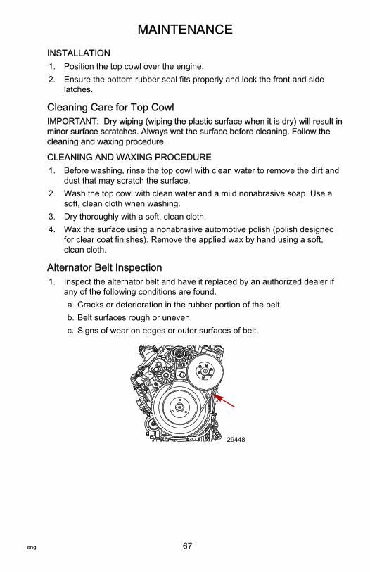
MAINTENANCE
eng 67
INSTALLATION1. Position the top cowl over the engine.2. Ensure the bottom rubber seal fits properly and lock the front and side
latches.
Cleaning Care for Top CowlIMPORTANT: Dry wiping (wiping the plastic surface when it is dry) will result inminor surface scratches. Always wet the surface before cleaning. Follow thecleaning and waxing procedure.
CLEANING AND WAXING PROCEDURE1. Before washing, rinse the top cowl with clean water to remove the dirt and
dust that may scratch the surface.2. Wash the top cowl with clean water and a mild nonabrasive soap. Use a
soft, clean cloth when washing.3. Dry thoroughly with a soft, clean cloth.4. Wax the surface using a nonabrasive automotive polish (polish designed
for clear coat finishes). Remove the applied wax by hand using a soft,clean cloth.
Alternator Belt Inspection1. Inspect the alternator belt and have it replaced by an authorized dealer if
any of the following conditions are found.a. Cracks or deterioration in the rubber portion of the belt.b. Belt surfaces rough or uneven.c. Signs of wear on edges or outer surfaces of belt.
29448

MAINTENANCE
68 eng
Fuel System
! WARNINGFuel is flammable and explosive. Ensure that the key switch is off and thelanyard is positioned so that the engine cannot start. Do not smoke or allowsources of spark or open flame in the area while servicing. Keep the workarea well ventilated and avoid prolonged exposure to vapors. Always checkfor leaks before attempting to start the engine, and wipe up any spilled fuelimmediately.
Before servicing any part of the fuel system, stop the engine and disconnectthe battery. Drain the fuel system completely. Use an approved container tocollect and store fuel. Wipe up any spillage immediately. Material used tocontain spillage must be disposed of in an approved receptacle. Any fuelsystem service must be performed in a well‑ventilated area. Inspect anycompleted service work for sign of fuel leakage.
FUEL LINE INSPECTIONVisually inspect the fuel line and primer bulb for cracks, swelling, leaks,hardness, or other signs of deterioration or damage. If any of these conditionsare found, the fuel line or primer bulb must be replaced.
FUEL FILTER REPLACEMENT
Removal1. Disconnect the link rod.2. Use a fuel filter removal installation tool, or use the shaft of a screwdriver
between the lugs on the filter cap and unscrew the filter.
Fuel Filter Removal/Installation Tool 91‑896661
24896
Aids in the removal and installation ofthe fuel filter cap assembly.

MAINTENANCE
eng 69
Installation1. Lubricate the O‑ring seals with oil.
a - Filterb - O‑ring sealsc - Link rod
2. Install the fuel filter and tighten securely.3. Connect the link rod.IMPORTANT: Visually inspect for fuel leakage from the filter while squeezingthe primer bulb until firm, forcing fuel into the filter.
DRAINING WATER FROM THE FUEL FILTER CHAMBERNOTE: If a sufficient amount of water has accumulated in the fuel filterchamber, the warning system will turn on. Draining the water from the fuel filterchamber is required.1. Pull the drain hose off the right side fitting. Hold the open end of the hose
over a container.2. Use a 1/8 in. hex wrench and loosen the drain screw and drain the fuel
filter chamber.
a
bc
29599
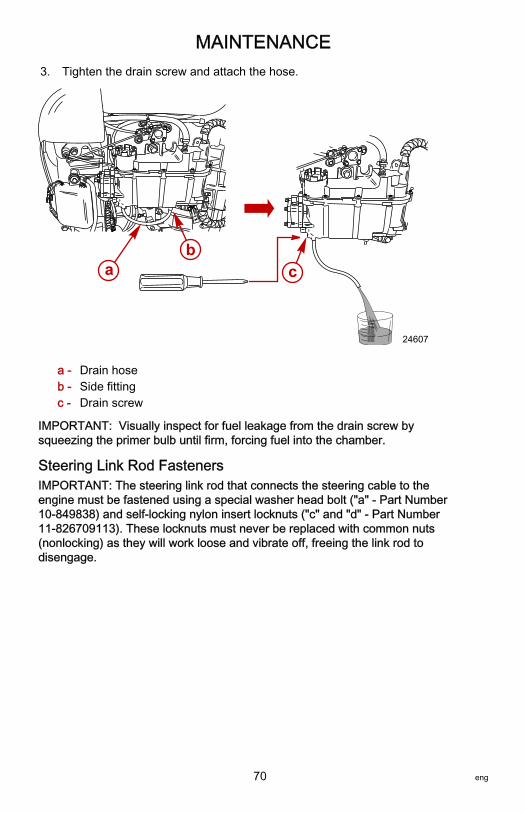
MAINTENANCE
70 eng
3. Tighten the drain screw and attach the hose.
a - Drain hoseb - Side fittingc - Drain screw
IMPORTANT: Visually inspect for fuel leakage from the drain screw bysqueezing the primer bulb until firm, forcing fuel into the chamber.
Steering Link Rod FastenersIMPORTANT: The steering link rod that connects the steering cable to theengine must be fastened using a special washer head bolt ("a" ‑ Part Number10‑849838) and self‑locking nylon insert locknuts ("c" and "d" ‑ Part Number11‑826709113). These locknuts must never be replaced with common nuts(nonlocking) as they will work loose and vibrate off, freeing the link rod todisengage.
cab
24607

MAINTENANCE
eng 71
! WARNINGImproper fasteners or improper installation procedures can result inloosening or disengagement of the steering link rod. This can cause asudden, unexpected loss of boat control, resulting in serious injury or deathdue to occupants being thrown within or out of the boat. Always use requiredcomponents and follow instructions and torque procedures.
a - Special washer head bolt (10‑849838)b - Flat washer (2)c - Nylon insert locknut (11‑826709113)d - Nylon insert locknut (11‑826709113)
Description Nm lb‑in. lb‑ft
Special washer head bolt 27 – 20
Nylon insert locknut "d" 27 – 20
Nylon insert locknut "c" Tighten until it seats, then back off 1/4turn
Assemble steering link rod to steering cable with two flat washers andself‑locking nylon insert locknut. Tighten locknut until it seats, then back nut off1/4 turn.Assemble steering link rod to engine with special washer head bolt andself‑locking nylon insert locknut. First torque bolt, then torque locknut tospecifications.
FusesIMPORTANT: Always carry spare 2‑, 15‑, and 20‑amp fuses.
ab
c
d 27843
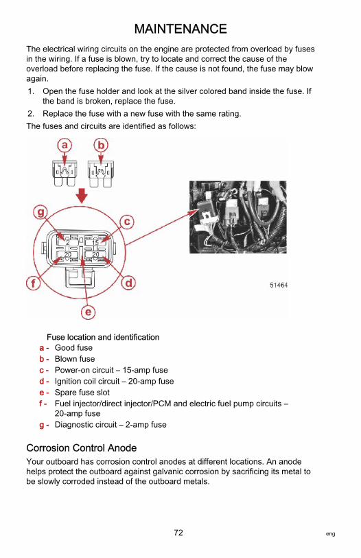
MAINTENANCE
72 eng
The electrical wiring circuits on the engine are protected from overload by fusesin the wiring. If a fuse is blown, try to locate and correct the cause of theoverload before replacing the fuse. If the cause is not found, the fuse may blowagain.1. Open the fuse holder and look at the silver colored band inside the fuse. If
the band is broken, replace the fuse.2. Replace the fuse with a new fuse with the same rating.The fuses and circuits are identified as follows:
Fuse location and identificationa - Good fuseb - Blown fusec - Power‑on circuit – 15‑amp fused - Ignition coil circuit – 20‑amp fusee - Spare fuse slotf - Fuel injector/direct injector/PCM and electric fuel pump circuits –
20‑amp fuseg - Diagnostic circuit – 2‑amp fuse
Corrosion Control AnodeYour outboard has corrosion control anodes at different locations. An anodehelps protect the outboard against galvanic corrosion by sacrificing its metal tobe slowly corroded instead of the outboard metals.

MAINTENANCE
eng 73
Each anode requires periodic inspection, especially in saltwater which willaccelerate the erosion. To maintain this corrosion protection, always replacethe anode before it is completely eroded. Never paint or apply a protectivecoating on the anode, as this will reduce effectiveness of the anode.The gearcase has three anodes. Two anodes are located on each side of thegearcase, and a third is an anode plate installed underneath the anti‑ventilationplate. If a trim tab should be installed, this anode plate will be removed. Anotheranode is installed on the bottom of the transom bracket assembly.
a - Corrosion controlanodes (gearcase)
b - Corrosion control anode(transom bracket)
Battery InspectionThe battery should be inspected at periodic intervals to ensure proper enginestarting capability.IMPORTANT: Read the safety and maintenance instructions which accompanyyour battery.1. Turn off the engine before servicing the battery.2. Ensure the battery is secure against movement.3. Battery cable terminals should be clean, tight, and correctly installed.
Positive to positive and negative to negative.4. Ensure the battery is equipped with a nonconductive shield to prevent
accidental shorting of battery terminals.
Battery Information (All Batteries Including DTS)
! WARNINGFailure to properly secure the battery leads can result in a loss of power tothe Digital Throttle and Shift (DTS) system, leading to serious injury or deathdue to loss of boat control. Secure the battery leads to the battery posts withhex nuts to avoid loose connections.
• Do not use deep cycle batteries. The engine must use a marine startingbattery with 1000 MCA, 800 CCA, or 180 Ah rating.

MAINTENANCE
74 eng
• When connecting the engine battery, use hex nuts to secure the batteryleads to the battery posts. Tighten the nuts to the specified torque.
Description Nm lb‑in. lb‑ft
Hex nuts 13.5 120 –
A decal advising against using deep cycle batteries and wing nuts should beplaced on or near the battery box for future service reference. One 5/16 in. andone 3/8 in. hex nut is supplied per battery for wing nut replacement. Metric hexnuts are not supplied.
54395
Propeller Replacement
! WARNINGRotating propellers can cause serious injury or death. Never operate the boatout of the water with a propeller installed. Before installing or removing apropeller, place the drive unit in neutral and engage the lanyard stop switchto prevent the engine from starting. Place a block of wood between thepropeller blade and the anti‑ventilation plate.

MAINTENANCE
eng 75
1. Shift the outboard to neutral (N) position.
N
26838
IMPORTANT: Refer to Spark Plug Inspection and Replacement for removingthe spark plug leads.2. Remove the spark plug leads to prevent engine from starting.
26899
3. Straighten the bent tabs on the propeller nut retainer.
26900

MAINTENANCE
76 eng
4. Place a block of wood between the gearcase and the propeller to hold thepropeller and remove the propeller nut.
26901
5. Pull the propeller straight off the shaft. If propeller is seized to the shaftand cannot be removed, have the propeller removed by an authorizeddealer.
6. Coat the propeller shaft with Quicksilver or Mercury Precision LubricantsExtreme Grease or 2‑4‑C with PTFE.
26902
Tube RefNo. Description Where Used Part No.
95 2-4-C with PTFE Propeller shaft 92-802859A 1
Extreme Grease Propeller shaft 8M0071842
IMPORTANT: To prevent the propeller hub from corroding and seizing to thepropeller shaft (especially in saltwater), always apply a coat of therecommended lubricant to the entire propeller shaft at the recommendedmaintenance intervals and also each time the propeller is removed.

MAINTENANCE
eng 77
7. Flo‑Torq I drive hub propellers ‑ Install forward thrust washer, propeller,continuity washer, rear thrust hub, propeller nut retainer, and propeller nutonto the shaft.
a - Propeller nutb - Propeller nut retainerc - Rear thrust hubd - Continuity washere - Propellerf - Forward thrust washer
8. Flo‑Torq II drive hub propellers ‑ Install forward thrust washer, replaceabledrive sleeve, propeller, thrust hub, propeller nut retainer, and propeller nutonto the shaft.
a - Propeller nutb - Propeller nut retainerc - Rear thrust hubd - Propellere - Replaceable drive
sleevef - Forward thrust washer
9. Place a block of wood between the gearcase and the propeller and torquethe propeller nut to specifications.
Description Nm lb‑in. lb‑ft
Propeller nut 75 – 55
10. Secure the propeller nut by bending three of the tabs into the thrust hubgrooves.
26945
a b c
d e f26908
a b c
d
e f
26941

MAINTENANCE
78 eng
Spark Plug Inspection and Replacement
! WARNINGDamaged spark plug boots may emit sparks that can ignite fuel vapors underthe engine cowl, resulting in serious injury or death from a fire or explosion.To avoid damaging the spark plug boots, do not use any sharp object ormetal tool to remove the spark plug boots.
1. Remove the spark plug leads by twisting the rubber boots while pullingthem off the spark plugs.
26899
2. Remove the spark plugs. Replace the spark plug if the electrode is worn;the insulator is rough, cracked, broken, or blistered; or if the preciousmetal is not visible on the spark plug electrode.
IMPORTANT: The color of the plug may not accurately reflect its condition. Toaccurately diagnose a faulty plug, inspect the precious metal on the plug'selectrode. If no precious metal is visible, replace the plug.
a - Precious metal
a
9381

MAINTENANCE
eng 79
3. Set the spark plug gap. Refer to Specifications.
27848
a. All of the spark plugs should have the gap checked and corrected asnecessary before installation.
b. Measure the gap with a feeler gauge or pin gauge. Never use awedge‑type gap checking tool to inspect or to adjust the gap.
c. If an adjustment is necessary, do not pry or apply any force on thecenter electrode. This is critical with any type of spark plug that has awear surface, such as platinum or iridium added to either the groundelectrode or the center electrode.
d. When it is necessary to widen the gap, use a tool that only pulls backon the ground electrode without touching the center electrode, theporcelain, or the wear portion of the ground electrode.
e. When it is necessary to close the gap, gently tap the plug groundelectrode on a hard surface.
4. Before installing spark plugs, clean off any dirt on the spark plug seats.Install the plugs finger‑tight and then tighten an additional 1/4 turn ortighten to the specified torque.
Description Nm lb‑in. lb‑ft
Spark plug 27 – 20
Air Compressor FilterNOTE: The air compressor filter is only used on specific models.The filter should be inspected and replaced, if required, every 100 hours ofoperation, or once a season.
REMOVAL1. Open the clamp and lift out the filter housing. Rotate the filter housing 1/4
turn clockwise to the unlock position and remove the air filter.

MAINTENANCE
80 eng
2. Remove the hose cable tie and pull the air filter off the hose.
a - Air filterb - Nylon washerc - Rubber washerd - Clampe - Filter housingf - Cable tie
INSTALLATION1. Place the nylon washer and rubber washer onto the air filter and insert the
filter into the housing. Rotate the filter 1/4 turn to the lock position.2. Position the filter housing so the inlet hose is facing towards the back of
the engine. Install the hose and secure with a cable tie.
a
b
c
28732
d
e
f

MAINTENANCE
eng 81
3. Secure the filter housing with the clamp.
a - Air filterb - Filter housingc - Clampd - Inlet hose
Lubrication Points1. Lubricate the following with Extreme Grease.
Tube RefNo. Description Where Used Part No.
Extreme Grease Trim rod ball ends 8M0071842
• Trim rod ball ends ‑ Turn the ball ends to work the lubricant into theball sockets.
28458
2. Lubricate the following with Extreme Grease or 2‑4‑C with PTFE.
a
b
c
28738
d

MAINTENANCE
82 eng
Tube RefNo. Description Where Used Part No.
Extreme Grease Propeller shaft 8M0071842
95 2-4-C with PTFE Propeller shaft 92-802859A 1
• Propeller shaft ‑ Refer to Propeller Replacement for removal andinstallation of the propeller. Coat the entire propeller shaft withlubricant to prevent the propeller hub from corroding and seizing to theshaft.
26902
3. Lubricate the following with 2‑4‑C with PTFE or Extreme Grease.
Tube RefNo. Description Where Used Part No.
Extreme GreaseAlternator belt tensioner pivot shaft,swivel bracket, tilt support lever, tilt
tube, steering cable8M0071842
95 2-4-C with PTFEAlternator belt tensioner pivot shaft,swivel bracket, tilt support lever, tilt
tube, steering cable92-802859A 1
• Alternator belt tensioner pivot shaft ‑ Lubricate through fitting.
2884
• Swivel bracket ‑ Lubricate through fitting.

MAINTENANCE
eng 83
• Tilt support lever ‑ Lubricate through fitting.
a - Swivel bracketb - Tilt support lever
• Tilt tube ‑ Lubricate through fitting.
27874
! WARNINGIncorrect cable lubrication can cause hydraulic lock, leading to seriousinjury or death from loss of boat control. Completely retract the end of thesteering cable before applying lubricant.
• Steering cable ‑ Rotate steering wheel to fully retract the steeringcable end into the outboard tilt tube. Lubricate through fitting.
a - Fittingb - Cable end
4. Lubricate the following with lightweight oil.
a
b27873
a b
27875

MAINTENANCE
84 eng
• Steering link rod pivot points ‑ Lubricate pivot points.
27876
Checking Power Trim Fluid1. Tilt the outboard to the full up position and engage the tilt support lever.
27877
2. Remove the fill cap and check the fluid level. The fluid level should beeven with the bottom of the fill hole. Add Quicksilver or Mercury PrecisionLubricant Power Trim and Steering Fluid. If not available, use automotiveautomatic transmission fluid (ATF).
28460
Tube RefNo. Description Where Used Part No.
114 Power Trim andSteering Fluid Power trim system 92-858074K01

MAINTENANCE
eng 85
Gearcase LubricationWhen adding or changing gearcase lubricant, visually check for the presence ofwater in the lubricant. If water is present, it may have settled to the bottom andwill drain out prior to the lubricant, or it may be mixed with the lubricant, giving ita milky colored appearance. If water is noticed, have the gearcase checked byyour dealer. Water in the lubricant may result in premature bearing failure or, infreezing temperatures, will turn to ice and damage the gearcase.Examine the drained gearcase lubricant for metal particles. A small amount ofmetal particles indicates normal gear wear. An excessive amount of metalfilings or larger particles (chips) may indicate abnormal gear wear and shouldbe checked by an authorized dealer.
DRAINING GEARCASE1. Place the outboard in a vertical operating position.2. Remove the propeller. Refer to Propeller Replacement.3. Place the drain pan below the outboard.4. Remove the vent plug and fill/drain plug and drain lubricant.
a - Vent plugb - Fill/drain plug
GEARCASE LUBRICANT CAPACITYGearcase lubricant capacity is approximately 970 ml (32.8 fl oz).
GEARCASE LUBRICANT RECOMMENDATIONMercury or Quicksilver High Performance Gear Lubricant.
CHECKING LUBRICANT LEVEL AND REFILLING GEARCASE1. Place the outboard in a vertical operating position.2. Remove the vent plug/sealing washer.
a
b
22692
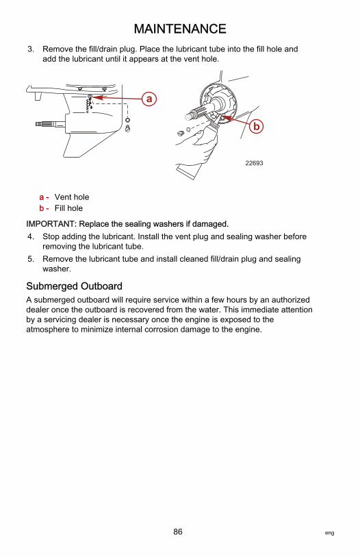
MAINTENANCE
86 eng
3. Remove the fill/drain plug. Place the lubricant tube into the fill hole andadd the lubricant until it appears at the vent hole.
a - Vent holeb - Fill hole
IMPORTANT: Replace the sealing washers if damaged.4. Stop adding the lubricant. Install the vent plug and sealing washer before
removing the lubricant tube.5. Remove the lubricant tube and install cleaned fill/drain plug and sealing
washer.
Submerged OutboardA submerged outboard will require service within a few hours by an authorizeddealer once the outboard is recovered from the water. This immediate attentionby a servicing dealer is necessary once the engine is exposed to theatmosphere to minimize internal corrosion damage to the engine.
a
b
22693

STORAGE
eng 87
Storage PreparationThe major consideration in preparing your outboard for storage is to protect itfrom rust, corrosion, and damage caused by freezing of trapped water.The following storage procedures should be followed to prepare your outboardfor out of season storage or prolonged storage (two months or longer).
NOTICEWithout sufficient cooling water, the engine, the water pump, and othercomponents will overheat and suffer damage. Provide a sufficient supply ofwater to the water inlets during operation.
Fuel SystemIMPORTANT: Gasoline containing alcohol (ethanol or methanol) can cause aformation of acid during storage and can damage the fuel system. If thegasoline being used contains alcohol, it is advisable to drain as much of theremaining gasoline as possible from the fuel tank, remote fuel line, and enginefuel system.The most effective method of storage preparation is to add the recommendedamount of Mercury Precision Fuel Stabilizer and Mercury Precision Quickleenproducts as described on the containers to the fuel tank before the lastoperation of the boat. Adding fuel stabilizer will help prevent the formation ofvarnish and gum in the gasoline. The Mercury Precision Quickleen product willhelp clean and lubricate the fuel injectors.1. Portable fuel tank ‑ Pour the required amount of gasoline stabilizer and
Quickleen (follow instructions on containers) into fuel tank. Tip fuel tankback and forth to mix stabilizer and Quickleen with the fuel.
2. Permanently installed fuel tank ‑ Pour the required amount of gasolinestabilizer and Quickleen (follow instructions on containers) into a separatecontainer and mix with approximately 1 liter (1 US qt) of gasoline. Pourthis mixture into fuel tank.
3. Pull the drain hose off the right side fitting. Hold the open end of the hoseover a container.

STORAGE
88 eng
4. Loosen drain screw and drain the fuel filter chamber.
a - Drain screwb - Drain hosec - Right side fitting
5. Tighten the drain screw and attach the hose.6. Pull the drain hose off the left side fitting. Hold the open end of the hose
over a container.7. Loosen the drain screw and drain the float chamber.
a - Left side fittingb - Drain screwc - Drain hose
8. Tighten the drain screw and attach the hose.9. Premix the following in a container:
a. 8 cc (0.27 oz) or 2 teaspoons of Mercury Precision Quickleenlubricant.
b. 8 cc (0.27 oz) or 2 teaspoons of Mercury Precision Fuel Stabilizer.10. Remove the fuel filter. See Maintenance ‑ Fuel System for procedure.11. Pour this mixture into the fuel filter opening. Install the fuel filter.12. Prime the fuel system. See Operation ‑ Starting The Engine.13. Place the outboard in water or use the flush hose or flushing device or for
circulating cooling water. Start the engine and run at idle speed for fiveminutes to allow the treated fuel to fill the fuel system.
a
b
c
23751
a bc
23752

STORAGE
eng 89
Flushing Device 91‑44357Q 2
9192
Attaches to the water intakes; providesa fresh water connection when flushingthe cooling system or operating theengine.
Protecting Internal Engine ComponentsNOTE: Make sure the fuel system has been prepared for storage. Refer to FuelSystem, preceding.IMPORTANT: Refer to Spark Plug Inspection and Replacement for correctprocedure for removing spark plug leads.1. Remove the spark plugs. Add approximately 30 ml (1 oz) of engine oil or
inject a five second spray of storage seal into each spark plug hole.2. Rotate the flywheel manually several times to distribute the oil or storage
seal in the cylinders.3. Install the spark plugs.
Protecting External Outboard Components• Lubricate all outboard components listed in Maintenance ‑ Inspection
and Maintenance Schedule.• Touch up any paint nicks. See your dealer for touch‑up paint.• Spray Quicksilver or Mercury Precision Lubricants Corrosion Guard on
external metal surfaces (except corrosion control anodes).
Tube RefNo. Description Where Used Part No.
120 Corrosion Guard External metal surfaces 92-802878 55
Gearcase• Drain and refill the gearcase lubricant (refer to Gearcase Lubrication).
Positioning Outboard for StorageStore outboard in an upright (vertical) position to allow water to drain out of theoutboard.

STORAGE
90 eng
NOTICEStoring the outboard in a tilted position can damage the outboard. Watertrapped in the cooling passages or rain water collected in the propellerexhaust outlet in the gearcase can freeze. Store the outboard in the full downposition.
Battery Storage• Follow the battery manufacturer's instructions for storage and charging.• Remove the battery from the boat and check water level. Charge if
necessary.• Store the battery in a cool, dry place.• Periodically check the water level and charge the battery during storage.

TROUBLESHOOTING
eng 91
Starter Motor Will Not Crank the EnginePOSSIBLE CAUSES• Blown 20‑amp fuse in the starting circuit. Refer to Maintenance.• Outboard is not shifted to neutral position.• Weak battery or battery connections are loose or corroded.• Ignition key switch failure.• Wiring or electrical connection faulty.• Starter motor solenoid or slave solenoid failure.
Engine Will Not StartPOSSIBLE CAUSES• Lanyard stop switch not in "RUN" position.• Battery not fully charged.• Incorrect starting procedure. Refer to Operation section.• Old or contaminated fuel.• Fuel is not reaching the engine.
• Fuel tank is empty.• Fuel tank vent not open or restricted.• Fuel line is disconnected or kinked.• Primer bulb not squeezed.• Primer bulb check valve is faulty.• Fuel filter is obstructed. Refer to Maintenance section.• Fuel pump failure.• Fuel tank filter obstructed.
• Open 20‑amp fuse. Check fuses, refer to Maintenance section.• Threaded connection of an air hose is loose.• Ignition system component failure.• Spark plugs fouled or defective. Refer to Maintenance section.
Engine Runs ErraticallyPOSSIBLE CAUSES• Spark plugs fouled or defective. Refer to Maintenance section.• Incorrect setup and adjustments.• Fuel is being restricted to the engine.
a. Engine fuel filter is obstructed. Refer to Maintenance section.b. Fuel tank filter obstructed.c. Stuck antisiphon valve on built‑in fuel tank.

TROUBLESHOOTING
92 eng
d. Fuel line is kinked or pinched.e. Injector plugged.
• Threaded connection of an air hose is loose.• Fuel pump failure.• Ignition system component failure.
Performance LossPOSSIBLE CAUSES• Throttle not fully open.• Damaged propeller or improper propeller size.• Boat overloaded or load improperly distributed.• Excessive water in bilge.• Boat bottom is dirty or damaged.
Warning Horn Activates (With Power Loss)POSSIBLE CAUSES• Intermittent horn sound:
• The oil level in the engine‑mounted oil reservoir tank is low. Refill thereservoir tank and the remote oil tank. Refer to Fuel and Oil fordetails.
• Battery voltage is out of limits.• Throttle position sensor failure.
• Continuous horn sound:• The oil level in the engine‑mounted oil reservoir tank is critically low.
Refill the reservoir tank and the remote oil tank. Refer to Fuel and Oilfor details.
• The oil pump has failed, halting the oil supply to the engine.• Engine speed exceeds the maximum‑allowable RPM. The system
limits the engine to within the allowable range. If the overspeedcondition continues, Engine Guardian places the engine into powerreduction. Overspeed may be caused by incorrect propeller pitch,engine height, trim angle, etc.
• High engine temperature or low block water pressure.• Cooling system clogged.• Incorrect transom height (water pickups not getting adequate water
supply).
Warning Horn Activates (No Power Loss)POSSIBLE CAUSES• Warning horn activates on start up. This is normal operation.

TROUBLESHOOTING
eng 93
• Water is detected in the water‑separating fuel filter. Refer to Maintenancefor procedures on removing water from the filter.
Battery Will Not Hold ChargePOSSIBLE CAUSES• Battery connections are loose or corroded.• Low electrolyte level in battery.• Worn out or inefficient battery.• Excessive use of electrical accessories.• Defective rectifier, alternator, or voltage regulator.• Open circuit in the alternator output wire (fused link).

OWNER SERVICE ASSISTANCE
94 eng
Local Repair ServiceAlways return your outboard to your local authorized dealer should the need forservice arise. Only he has the factory trained mechanics, knowledge, specialtools, equipment, and genuine parts and accessories to properly service yourengine should the need occur. He knows your engine best.
Service Away from HomeIf you are away from your local dealer and the need arises for service, contactthe nearest authorized dealer. Refer to the Yellow Pages of the telephonedirectory. If, for any reason, you cannot obtain service, contact the nearestMercury Marine Service Office.
Parts and Accessories InquiriesAll inquiries concerning genuine replacement parts and accessories should bedirected to your local authorized dealer. The dealer has the necessaryinformation to order parts and accessories for you. When inquiring about partsand accessories, the dealer requires the model and serial number to order thecorrect parts.
Service AssistanceLOCAL REPAIR SERVICEIf you need service for your Mercury‑outboard‑powered boat, take it to yourauthorized dealer. Only authorized dealers specialize in Mercury products andhave factory‑trained mechanics, special tools and equipment, and genuineQuicksilver parts and accessories to properly service your engine.NOTE: Quicksilver parts and accessories are engineered and built by MercuryMarine specifically for your power package.
SERVICE AWAY FROM HOMEIf you are away from your local dealer and the need arises for service, contactthe nearest authorized dealer. If, for any reason, you cannot obtain service,contact the nearest Regional Service Center. Outside the United States andCanada, contact the nearest Marine Power International Service Center.
STOLEN POWER PACKAGEIf your power package is stolen, immediately advise the local authorities andMercury Marine of the model and serial numbers and to whom the recovery isto be reported. This information is maintained in a database at Mercury Marineto aid authorities and dealers in the recovery of stolen power packages.
ATTENTION REQUIRED AFTER SUBMERSION1. Before recovery, contact an authorized Mercury dealer.2. After recovery, immediate service by an authorized Mercury dealer is
required to reduce the possibility of serious engine damage.

OWNER SERVICE ASSISTANCE
eng 95
REPLACEMENT SERVICE PARTS
! WARNINGAvoid fire or explosion hazard. Electrical, ignition, and fuel systemcomponents on Mercury Marine products comply with federal andinternational standards to minimize risk of fire or explosion. Do not usereplacement electrical or fuel system components that do not comply withthese standards. When servicing the electrical and fuel systems, properlyinstall and tighten all components.
Marine engines are expected to operate at or near full throttle for most of theirlives. They are also expected to operate in both fresh and saltwaterenvironments. These conditions require numerous special parts.
PARTS AND ACCESSORIES INQUIRIESDirect any inquiries concerning Quicksilver replacement parts and accessoriesto your local authorized dealer. The dealer has the necessary information toorder parts and accessories for you if they are not in stock. Only authorizeddealers can purchase genuine Quicksilver parts and accessories from thefactory. Mercury Marine does not sell to unauthorized dealers or retailcustomers. When inquiring about parts and accessories, the dealer requires theengine model and serial numbers to order the correct parts.
RESOLVING A PROBLEMSatisfaction with your Mercury product is important to your dealer and to us. Ifyou ever have a problem, question or concern about your power package,contact your dealer or any authorized Mercury dealership. If you needadditional assistance:1. Talk with the dealership's sales manager or service manager. Contact the
owner of the dealership if the sales manager and service manager havebeen unable to resolve the problem.
2. If your question, concern, or problem cannot be resolved by yourdealership, please contact the Mercury Marine Service Office forassistance. Mercury Marine will work with you and your dealership toresolve all problems.
The following information will be needed by the Customer Service:• Your name and address• Your daytime telephone number• The model and serial numbers of your power package• The name and address of your dealership• The nature of the problem

OWNER SERVICE ASSISTANCE
96 eng
CONTACT INFORMATION FOR MERCURY MARINE CUSTOMERSERVICEFor assistance, call, fax, or write to the geographic office in your area. Pleaseinclude your daytime telephone number with mail and fax correspondence.
United States, Canada
Telephone English +1 920 929 5040Français +1 905 636 4751
Mercury MarineW6250 Pioneer RoadP.O. Box 1939Fond du Lac, WI 54936-1939Fax English +1 920 929 5893
Français +1 905 636 1704
Website www.mercurymarine.com
Australia, Pacific
Telephone +61 3 9791 5822 Brunswick Asia Pacific Group41–71 Bessemer DriveDandenong South, Victoria 3175Australia
Fax +61 3 9706 7228
Europe, Middle East, Africa
Telephone +32 87 32 32 11 Brunswick Marine EuropeParc Industriel de Petit-RechainB-4800 Verviers,Belgium
Fax +32 87 31 19 65
Mexico, Central America, South America, Caribbean
Telephone +1 954 744 3500 Mercury Marine11650 Interchange Circle NorthMiramar, FL 33025U.S.A.
Fax +1 954 744 3535
Japan
Telephone +072 233 8888 Kisaka Co., Ltd.4‑130 Kannabecho, Sakai‑kuSakai‑shi, Osaka 590‑0984, JapanFax +072 233 8833
Asia, Singapore
Telephone +65 65466160 Brunswick Asia Pacific GroupT/A Mercury Marine Singapore Pte Ltd29 Loyang DriveSingapore, 508944
Fax +65 65467789

OWNER SERVICE ASSISTANCE
eng 97
Ordering LiteratureBefore ordering literature, have the following information about your powerpackage available:
Model Serial Number
Horsepower Year
UNITED STATES AND CANADAFor additional literature for your Mercury Marine power package, contact yournearest Mercury Marine dealer or contact:
Mercury Marine
Telephone Fax Mail
(920) 929‑5110(USA only)
(920) 929‑4894(USA only)
Mercury MarineAttn: Publications Department
P.O. Box 1939Fond du Lac, WI 54935-1939
OUTSIDE THE UNITED STATES AND CANADAContact your nearest Mercury Marine authorized service center to orderadditional literature that is available for your particular power package.
Submit the followingorder form with paymentto:
Mercury MarineAttn: Publications DepartmentW6250 Pioneer RoadP.O. Box 1939Fond du Lac, WI 54936-1939
Ship To: (Copy this form and print or type–This is your shipping label)
Name
Address
City, State, Province
ZIP or postal code
Country
Quantity Item Stock Number Price Total
. .
. .
. .
. .

OWNER SERVICE ASSISTANCE
98 eng
Quantity Item Stock Number Price Total
. .
Total Due .

OUTBOARD INSTALLATION
eng 99
Mercury Marine Validated Engine Mounting HardwareIMPORTANT: Mercury Marine provides validated fasteners and installationinstructions, including torque specifications, with all of our outboards so theycan be properly secured to boat transoms. Improper installation of the outboardcan cause performance and reliability issues that can lead to safety concerns.Follow all of the instructions relating to the outboard installation. DO NOTmount any other accessory onto the boat with the fasteners provided with theoutboard. For example, do not mount a tow sport bars or boarding ladders ontothe boat using the mounting hardware included with the outboard. Installingother products onto the boat that utilize the outboard mounting hardware willcompromise the ability of that hardware to properly and safely secure theoutboard to the transom.Outboards that require validated mounting hardware will have the followingdecal on the transom clamp.
51965
Accessories Mounted to the Transom Clamp BracketMercury Marine has been made aware that certain aftermarket marineaccessories, such as emergency boarding ladders, shallow water anchors,transom wedge kits, and tow sport attaching devices, have been mounted tothe boat by use of the same fasteners that secure the outboard to the transomor jack plate. Using the same fastener to secure both an accessory and theengine to the boat compromises the ability of the fasteners to maintain theproper clamp load. A boat with loose engine mounting fasteners creates thepossibility of performance, durability, and safety issues.

OUTBOARD INSTALLATION
100 eng
! WARNINGAvoid serious injury or death resulting from a loss of boat control. Looseengine fasteners could cause the transom bracket to fail, resulting in a loss ofthe driver's ability to control the boat. Always ensure that the enginefasteners are tightened to the specified torque.
ACCEPTABLE ACCESSORY MOUNTING TO THE TRANSOM CLAMPBRACKETAfter the engine is mounted to the transom or jack plate in accordance with theengine installation instructions, it is acceptable to attach an accessory to theboat by use of the unused bolt holes in the transom clamp bracket as shown inFigure 1.The following list provides additional guidelines for mounting accessories to thetransom clamp bracket.• The accessory fasteners must pass through the boat transom or jack
plate.

OUTBOARD INSTALLATION
eng 101
• The installation must not create interference issues, as would anaccessory mounting plate resting in the radius of the transom clampbracket. Refer to Figure 1.
Figure 1a - Minimum clearance 3.175 mm (0.125 in.)b - Edge of accessory bracketc - Transom clamp bracket walld - Radiuse - Engine supplied mounting fastenersf - Fasteners supplied by the accessory manufacturer installed through
unused engine mounting bracket holes
b
c
d
af
54624
e
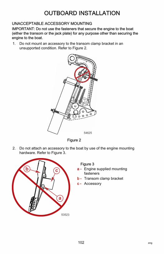
OUTBOARD INSTALLATION
102 eng
UNACCEPTABLE ACCESSORY MOUNTINGIMPORTANT: Do not use the fasteners that secure the engine to the boat(either the transom or the jack plate) for any purpose other than securing theengine to the boat.1. Do not mount an accessory to the transom clamp bracket in an
unsupported condition. Refer to Figure 2.
54625
Figure 2
2. Do not attach an accessory to the boat by use of the engine mountinghardware. Refer to Figure 3.
Figure 3a - Engine supplied mounting
fastenersb - Transom clamp bracketc - Accessory
53523
a
b c

OUTBOARD INSTALLATION
eng 103
3. Do not install wedges or plates between the transom clamp brackets andthe transom (or jack plate). Refer to Figure 4.
Figure 4a - Boat transom or jack plateb - Transom clamp bracketc - Wedge/plate
Boat Horsepower Capacity
! WARNINGExceeding the boat's maximum horsepower rating can cause serious injuryor death. Overpowering the boat can affect boat control and flotationcharacteristics or break the transom. Do not install an engine that exceedsthe boat's maximum power rating.
Do not overpower or overload your boat. Most boats will carry a requiredcapacity plate indicating the maximum acceptable power and load asdetermined by the manufacturer following certain federal guidelines. If in doubt,contact your dealer or the boat manufacturer.
U.S. COAST GUARD CAPACITYMAXIMUM HORSEPOWER XXXMAXIMUM PERSON CAPACITY (POUNDS) XXXMAXIMUM WEIGHT CAPACITY XXX
26777
Start in Gear Protection
! WARNINGStarting the engine with the drive in gear can cause serious injury or death.Never operate a boat that does not have a neutral‑safety‑protection device.
54058c
ba

OUTBOARD INSTALLATION
104 eng
The remote control connected to the outboard must be equipped with a start inneutral only protection device. This prevents the engine from starting in gear.
Selecting Accessories for Your OutboardGenuine Mercury Precision or Quicksilver Accessories have been specificallydesigned and tested for this outboard.Some accessories not manufactured or sold by Mercury Marine are notdesigned to be safely used with this outboard or outboard operating system.Acquire and read the installation, operation, and maintenance manuals for allselected accessories.
Fuel System
AVOIDING FUEL FLOW RESTRICTIONIMPORTANT: Adding components to the fuel supply system (filters, valves,fittings, etc.) may restrict the fuel flow. This may cause engine stalling at lowspeed, and/or a lean fuel condition at high RPM that could cause enginedamage.
ELECTRIC FUEL PUMPThe fuel pressure must not exceed 28 kPa (4 psi). If necessary, install apressure regulator.
LOW PERMEATION FUEL HOSE REQUIREMENTRequired for outboards manufactured for sale, sold, or offered for sale in theUnited States.• The Environmental Protection Agency (EPA) requires that any outboard
manufactured after January 1, 2009, must use low permeation fuel hosefor the primary fuel hose connecting the fuel tank to the outboard.
• Low permeation hose is USCG Type B1‑15 or Type A1‑15, defined as notexceeding 15/gm²/24 h with CE 10 fuel at 23 °C as specified in SAE J1527 ‑ marine fuel hose.
EPA PRESSURIZED PORTABLE FUEL TANK REQUIREMENTSThe Environmental Protection Agency (EPA) requires portable fuel systemsthat are produced after January 1, 2011, for use with outboard engines toremain fully sealed (pressurized) up to 34.4 kPa (5.0 psi). These tanks maycontain the following:• An air inlet that opens to allow air to enter as the fuel is drawn out of the
tank.• An air outlet that opens (vents) to the atmosphere if pressure exceeds
34.4 kPa (5.0 psi).
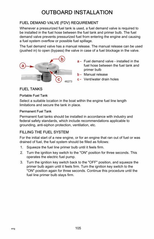
OUTBOARD INSTALLATION
eng 105
FUEL DEMAND VALVE (FDV) REQUIREMENTWhenever a pressurized fuel tank is used, a fuel demand valve is required tobe installed in the fuel hose between the fuel tank and primer bulb. The fueldemand valve prevents pressurized fuel from entering the engine and causinga fuel system overflow or possible fuel spillage.The fuel demand valve has a manual release. The manual release can be used(pushed in) to open (bypass) the valve in case of a fuel blockage in the valve.
a - Fuel demand valve ‑ installed in thefuel hose between the fuel tank andprimer bulb
b - Manual releasec - Vent/water drain holes
FUEL TANKS
Portable Fuel TankSelect a suitable location in the boat within the engine fuel line lengthlimitations and secure the tank in place.
Permanent Fuel TankPermanent fuel tanks should be installed in accordance with industry andfederal safety standards, which include recommendations applicable togrounding, anti‑siphon protection, ventilation, etc.
FILLING THE FUEL SYSTEMFor the initial start of a new engine, or for an engine that ran out of fuel or wasdrained of fuel, the fuel system should be filled as follows:1. Squeeze the fuel line primer bulb until it feels firm.2. Turn the ignition key switch to the "ON" position for three seconds. This
operates the electric fuel pump.3. Turn the ignition key switch back to the "OFF" position, and squeeze the
primer bulb again until it feels firm. Turn the ignition key switch to the"ON" position again for three seconds. Continue this procedure until thefuel line primer bulb stays firm.
a
c
b
46273
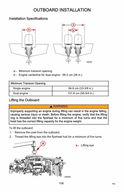
OUTBOARD INSTALLATION
106 eng
Installation Specifications
a - Minimum transom openingb - Engine centerline for dual engine ‑ 66.0 cm (26 in.)
Minimum Transom Opening
Single engine 84.8 cm (33‑3/8 in.)
Dual engine 151.8 cm (59‑3/4 in.)
Lifting the Outboard
! WARNINGImproperly supporting an engine during lifting can result in the engine falling,causing serious injury or death. Before lifting the engine, verify that the liftingring is threaded into the flywheel for a minimum of five turns and that thehoist has the correct lifting capacity for the engine weight.
To lift the outboard:1. Remove the cowl from the outboard.2. Thread the lifting eye into the flywheel hub for a minimum of five turns.
a - Lifting eye
18552
aa
b
a
28495

OUTBOARD INSTALLATION
eng 107
3. Connect a hoist to the lifting eye.4. Lift the outboard and place it on the boat transom.
Lifting Eye 91‑90455‑‑1
2756
Threads into the flywheel to remove thepowerhead assembly from the driveshafthousing, or to lift entire engine forremoval/installation.
Steering Cable ‑ Starboard Side Routed Cable1. Lubricate the O‑ring seal and the entire cable end.
3724
95
Tube RefNo. Description Where Used Part No.
95 2-4-C with PTFE O-ring seal and entire cable end 92-802859A 1
2. Insert the steering cable into the tilt tube.
3725

OUTBOARD INSTALLATION
108 eng
3. Tighten the nut to the specified torque.
3727
Description Nm lb‑in. lb‑ft
Nut 47.5 – 35
Steering Link Rod FastenersIMPORTANT: The steering link rod that connects the steering cable to theengine must be fastened using a special washer head bolt (P/N 10‑849838)and self‑locking nylon insert locknuts (P/N 11‑826709113). Never replacelocknuts with common nuts (nonlocking) as they will work loose and vibrate off,freeing the link rod to disengage.
! WARNINGImproper fasteners or improper installation procedures can result inloosening or disengagement of the steering link rod. This can cause asudden, unexpected loss of boat control, resulting in serious injury or deathdue to occupants being thrown within or out of the boat. Always use requiredcomponents and follow instructions and torque procedures.

OUTBOARD INSTALLATION
eng 109
! WARNINGWorn, loose, or seized steering components can lead to loss of boat control.Inspect all steering attachment components for wear, lubricate all attachmenthardware, and check all fasteners for proper tightness in accordance with theinspection and maintenance schedule.
a - Special washer head bolt (P/N 10‑849838)b - Nylon insert locknut (P/N 11‑826709113) ‑ used on head boltc - Flat washer (2)d - Nylon insert locknut (P/N 11‑826709113) ‑ used on cable coupler
1. Assemble steering link rod to steering cable coupler with two flat washers"c" and a self‑locking nylon insert locknut "d." Tighten the locknut until itseats, then loosen ¼ turn.
2. Assemble the steering link rod to the engine with the special washer headbolt "a" and self‑locking nylon insert locknut "b."
3. Torque the head bolt, then the locknut to specifications.
Description Nm lb‑in. lb‑ft
Cable coupler nylon insert locknut"d"
Tighten locknut until it seats, thenloosen ¼ turn.
Head bolt nylon insert locknut "b" 27 – 20
Special washer head bolt 27 – 20
2767
a
b
c
d

OUTBOARD INSTALLATION
110 eng
Recommended Mounting Height
DETERMINING OUTBOARD MOUNTING HEIGHT FOR A STANDARDGEAR HOUSING
Standard 20-inch (L) mounting bracket grapha - The solid line is recommended to determine the outboard mounting
height.b - The broken lines represent the extremes of known successful outboard
mounting height dimensions.c - This line may be preferred to determine outboard mounting height
dimension, if maximum speed is the only objective.d - This line may be preferred to determine outboard mounting height
dimension for dual outboard installation.e - Outboard mounting height (height of outboard mounting brackets from
bottom of boat transom). For heights over 56.0 cm (22 in.), a propellerthat is designed for piercing the water surface is usually preferred.
f - Maximum boat speed anticipated.
(20 in.)
(21 in.)
(22 in.)
(23 in.)
(24 in.)
(25 in.)
(19 in.)
10 20 30 40 50 60 70 80
63.5 cm
60.9 cm
58.4 cm
56.0 cm
53.3 cm
50.8 cm
48.2 cm
f
e bc
d
a
e
24305
OUTBOARD INSTALLATION
eng 111
NOTICE
1. The outboard should be mounted high enough on the transom so thatthe exhaust relief hole will stay at least 25.4 mm (1 in.) above thewaterline when the engine is running at idle speed. Having the exhaustrelief hole above the waterline will prevent exhaust restrictions. Exhaustrestrictions will result in poor performance at idle.
2. Add 12.7 cm (5 in.) for XL models to the listed outboard mountingheights.
3. The mounting height of the outboard must not exceed 63.5 cm (25 in.)for L models, 76 cm (30 in.) for XL models. Mounting the outboard highermay cause damage to the gearcase components.
Increasing the mounting height will usually:• Reduce steering torque• Increase top speed• Increase boat stability• Cause the propeller to break loose during planing

OUTBOARD INSTALLATION
112 eng
DETERMINING OUTBOARD MOUNTING HEIGHT FOR A TORQUEMASTER GEN 2 GEAR HOUSINGThe following mounting height information is a general guideline for mostapplications. Every boat has a unique characteristic that may require themounting height to be changed from the guidelines explained here. Installing aset‑back bracket or jackplate is the responsibility of the installer to verify theinstallation is the right combination for the boat.
Standard 20-inch (L) mounting bracket grapha - The solid line is recommended to determine the outboard mounting
heightb - The broken lines represent the extremes of known successful outboard
mounting height dimensionsc - This line may be preferred to determine outboard mounting height
dimension, if maximum speed is the only objectived - This line may be preferred to determine outboard mounting height
dimension for dual outboard installatione - Outboard mounting height (height of outboard mounting brackets from
bottom of boat transom). For heights over 56.0 cm (22 in.), a propellerthat is designed for piercing the water surface is usually preferred.
NOTE: For 63.5 cm (25 in.) (XL) models, add 12.7 cm (5 in.) to the standard(L) measurement.IMPORTANT: Do not mount this engine higher than 66.04 cm (26 in.) on along (L) model or 78.9 cm (31 in.) on an extra‑long (XL) model. Mountingthese engines higher than the maximum recommended height, will causedamage to the gear housing. Damage caused from excessive mountingheight is not covered under the warranty policy.
(20 in.)
(21 in.)
(22 in.)
(23 in.)
(24 in.)
(25 in.)
(19 in.)
10 20 30 40 50 60 70 80
63.5 cm
60.9 cm
58.4 cm
56.0 cm
53.3 cm
50.8 cm
48.2 cm
f
e bc
d
a
e
24305

OUTBOARD INSTALLATION
eng 113
f - Maximum boat speed anticipated
NOTICE
1. The outboard should be mounted high enough on the transom so theexhaust relief hole will stay at least 25.4 mm (1 in.) above the waterlinewhen the engine is running at idle speed. Having the exhaust relief holeabove the waterline will prevent exhaust restrictions. Exhaust restrictionswill result in poor performance at idle.
2. Add 12.7 cm (5 in.) for XL models to the listed outboard mountingheights.
3. The mounting height of the outboard must not exceed 66.04 cm (26 in.)for L models, 78.9 cm (31 in.) for XL models. Mounting the outboardhigher will cause gearhousing damage.
Increasing the mounting height will usually:• Reduce steering torque• Increase top speed• Increase boat stability• Cause the propeller to break loose during planing
Drilling Outboard Mounting HolesIMPORTANT: Before drilling any mounting holes, carefully read DeterminingRecommended Outboard Mounting Height and install outboard to thenearest recommended mounting height.1. Mark four mounting holes on the transom using the transom drilling
fixture.
a - Drill guide holesb - Transom drilling fixturec - Transom centerline
2757
a
a
b
c

OUTBOARD INSTALLATION
114 eng
Transom Drilling Fixture 91‑98234A2
5489
Aids in engine installation by acting as atemplate for engine mounting holes.
2. Drill four 13.5 mm (17/32 in.) mounting holes.
3973
Fastening the Outboard to the TransomMOUNTING BOLTS
Outboard Transom Mounting Hardware ‑ Supplied with Outboard
Part Number Part Name Description
8M0033366 Outboard mounting bolt ½‑20 x 5.00 in. long (3.25 in. thread)
826711‑17 Nylon insert locknut ½‑20
28421 Flat washer 1.50 in. diameter
54012 Flat washer 0.875 in. diameter
Available Outboard Mounting Bolts
Part Number Description
67755005 ½‑20 x 2.50 in. long (1.25 in. thread)
67755006 ½‑20 x 3.50 in. long (1.25 in. thread)
814259 ½‑20 x 4.00 in. long (2.25 in. thread)
67755‑1 ½‑20 x 4.50 in. long (2.25 in. thread)
8M0033366 ½‑20 x 5.00 in. long (3.25 in. thread)
67755‑003 ½‑20 x 5.50 in. long (3.25 in. thread)

OUTBOARD INSTALLATION
eng 115
Available Outboard Mounting Bolts
Part Number Description
67755‑2 ½‑20 x 6.50 in. long (2.75 in. thread)
8M0028080 ½‑20 x 7.50 in. long (2.75 in. thread)
8M0032860 ½‑20 x 8.00 in. long (2.75 in. thread)
CHECKING BOAT TRANSOM CONSTRUCTIONIMPORTANT: Determine the strength of the boat transom. The outboardmounting locknuts and bolts should be able to hold 75 Nm (55 lb‑ft) of torquewithout the boat transom yielding or cracking. If the boat transom yields orcracks under this torque, the construction of the transom may not be adequate.The boat transom must be strengthened or the load carrying area increased.
a - Transom yielding under bolt torqueb - Transom cracking under bolt torque
18961
ab

OUTBOARD INSTALLATION
116 eng
Use a dial torque wrench to determine transom strength. If the bolt or nutcontinues to turn without the torque reading on the dial increasing, it is anindication that the transom is yielding. The load area can be increased by usinga larger washer or a transom reinforcement plate.
a - Large transom washerb - Transom reinforcement plate
FASTENING THE OUTBOARD TO THE TRANSOMIMPORTANT: The transom mounting surface must be flat within 3.17 mm(0.125 in.). No step in the transom mounting surface is allowed. The insidetransom mounting bolt washer surface must be flat within 3.17 mm (0.125 in.).
a - Step (not allowed)b - Gap between transom clamp and boat transom (not allowed)
a
b
33962
a
b
51817

OUTBOARD INSTALLATION
eng 117
IMPORTANT: Clearance must be maintained between the vessel transom andthe outboard transom bracket relief radius area. Failure to maintain clearancemay damage the transom bracket and cause the transom bracket to fail.Adjustments to the position of the Mercury Marine transom drilling fixture maybe required to ensure proper clearance of the transom bracket relief radiusarea.
51867
Installation1. Apply marine sealer to the shanks of the bolts, not to the threads.2. Fasten the outboard with the correct mounting hardware. Tighten the
locknuts to the specified torque.IMPORTANT: Ensure that a minimum of two full threads of the mounting boltsextend beyond the locknut after tightening. The locknut must be drawn tightwhile still engaging the bolt threads and not contacting the shank of the bolt.

OUTBOARD INSTALLATION
118 eng
NOTE: For a more accurate torque reading, tighten the mounting locknutsrather than the outboard mounting bolts.
a - 0.500 in. diameter outboard mounting bolt (4)b - 0.875 in. flat washer (4)c - Nylon insert locknut (4)d - 1.500 in. flat washer (4)e - Marine sealer – apply to the shank of the bolts, not the threads
Description Nm lb‑in. lb‑ft
Outboard mounting locknuts andbolts – standard boat transom 75 – 55
Outboard mounting locknuts andbolts – metal lift plates and setbackbrackets
122 – 90
a
c
d
ca
d
40952
be

OUTBOARD INSTALLATION
eng 119
A decal on the transom bracket reminds the owner to check the fastenerssecuring the outboard to the transom before each use.
51985
Decal on the transom bracket
Electrical, Hoses, Control Cables, and Front Clamp
REMOTE WIRING HARNESSRoute the remote 14 pin boat harness through the front clamp opening in thebottom cowl. Connect remote harness to the 14 pin connector on the engineharness.
a - 14 pin connector
a
28742

OUTBOARD INSTALLATION
120 eng
BATTERY INFORMATION (ALL BATTERIES INCLUDING DTS)
! WARNINGFailure to properly secure the battery leads can result in a loss of power tothe Digital Throttle and Shift (DTS) system, leading to serious injury or deathdue to loss of boat control. Secure the battery leads to the battery posts withhex nuts to avoid loose connections.
• Do not use deep cycle batteries. The engine must use a marine startingbattery with 1000 MCA, 800 CCA, or 180 Ah rating.
• When connecting the engine battery, use hex nuts to secure the batteryleads to the battery posts. Tighten the nuts to the specified torque.
Description Nm lb‑in. lb‑ft
Hex nuts 13.5 120 –
A decal advising against using deep cycle batteries and wing nuts should beplaced on or near the battery box for future service reference. One 5/16 in. andone 3/8 in. hex nut is supplied per battery for wing nut replacement. Metric hexnuts are not supplied.
54395
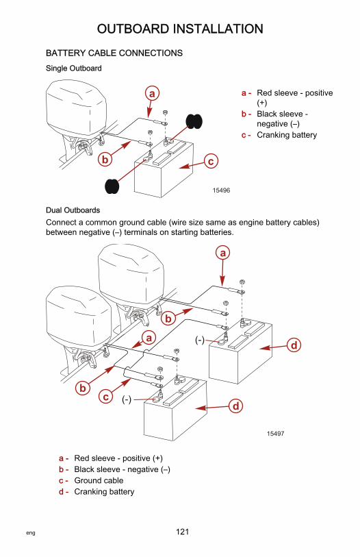
OUTBOARD INSTALLATION
eng 121
BATTERY CABLE CONNECTIONS
Single Outboard
a - Red sleeve ‑ positive(+)
b - Black sleeve ‑negative (–)
c - Cranking battery
Dual OutboardsConnect a common ground cable (wire size same as engine battery cables)between negative (–) terminals on starting batteries.
a - Red sleeve ‑ positive (+)b - Black sleeve ‑ negative (–)c - Ground cabled - Cranking battery
(+)(+)
(-)(-)
b
a
c
15496
(-)
(-)
a
ab
bc
d
d
15497

OUTBOARD INSTALLATION
122 eng
HOSE AND TUBING CONNECTIONS
Fuel HoseThe minimum fuel line inside diameter (I.D.) is 8 mm (5/16 in.), with a separatefuel line/fuel tank pickup for each engine.Fasten the remote fuel hose to the fitting with a hose clamp.
Oil HosesConnect the remote oil hoses to the engine hose connections. Fasten hoseconnections with cable ties.
Water Pressure and Speedometer Hose or TubingNOTE: This applies to models without SmartCraft gauges.This outboard has a speedometer water pickup located in the leading edge ofthe gearcase. If you want to use this water pickup for the speedometer,disconnect the water pickup tubing from the speedometer sensor and routetubing out of the cowl. Install the coupler provided with the outboard on the endof the tubing.

OUTBOARD INSTALLATION
eng 123
Make the water pressure gauge hose connection to the tubing as shown.
a - Water pressure tubeb - Speedometer water pickup tube (if required)c - Couplerd - Pluge - Barb hose fittingf - Speedometer hose or tubingg - Water pressure tubeh - Remote fuel hosei - Hose clampj - Oil hose with blue stripek - Oil hose without blue stripel - Cable tie
INSTALLING THE SHIFT CABLEIMPORTANT: The shift cable is the first cable to move when the remote controlhandle is moved out of neutral, so install/connect it to the engine first.
Locating the Center Point of the Shift CableIMPORTANT: Locate the center point of the slack or lost motion that exists inthe shift cable for proper adjustment of the shift cable.1. Mark the forward position as follows:
c
e d g f
ba
hi
j kl
j k 29069

OUTBOARD INSTALLATION
124 eng
a. Move the remote control handle from neutral into forward and advancethe handle to the full speed position. Ensure the throttle control lever istouching the throttle control lever stop screw.
b. Slowly return the handle back to the neutral detent position.c. Place a mark on the shift cable against the cable end guide.
a - Forward position mark
2. Mark the reverse position as follows:a. Move the remote control handle into reverse and advance the handle
to the full speed position. Ensure the throttle control lever is touchingthe throttle control lever stop screw.
b. Slowly return the handle back to the neutral detent position.c. Place a mark on the shift cable against the cable end guide.
a - Reverse position mark
3. Mark the center on the shift cable midway between the forward andreverse marks.
a - Center mark
a
29076
a
29077
4361
a

OUTBOARD INSTALLATION
eng 125
4. Align the cable end guide against this center mark when installing thecable to the engine.
5. Position the remote control and outboard into neutral position.6. Slide the anchor pin forward until resistance is felt, then slide the anchor
pin toward the rear until resistance is felt.7. Center the anchor pin between these resistance points.
a - Anchor pin
Adjusting the Shift Cable1. Align the shift cable end guide with the center mark as instructed in
Locating the Center Point of the Shift Cable.
a - Center mark
2. Place the shift cable end guide on the anchor pin and adjust the cablebarrel so that it slips freely into the barrel holder.
a
28746
4362a

OUTBOARD INSTALLATION
126 eng
3. Secure the shift cable to the anchor pin with the retainer clip.
a - Cable barrelb - Shift cable retainerc - Retainer clip
4. Check the shift cable adjustments as follows:a. Shift the remote control to forward while turning the propeller shaft. If
the propeller shaft does not lock in gear, adjust the cable barrel closerto the cable end guide.
b. Shift the remote control into neutral. If the propeller shaft does not turnfreely without drag, adjust the barrel away from the cable end guide.Repeat steps a and b.
c. Shift the remote control into reverse while turning the propeller shaft. Ifthe propeller shaft does not lock solidly in gear, adjust the barrel awayfrom the cable end guide. Repeat steps a through c.
d. Return the remote control handle to neutral. If the propeller shaft doesnot turn freely without drag, adjust the barrel closer to the cable endguide. Repeat steps a through d.
INSTALLING THE THROTTLE CABLEIMPORTANT: Attach the shift cable to the engine prior to attaching the throttlecable.1. Shift the remote control into the neutral position.2. Attach the throttle cable to the throttle lever. Secure with a washer and
locknut. Tighten the locknut to the specified value.
a - Nylon washerb - Locknut
a
b
c
28749
2678
ab

OUTBOARD INSTALLATION
eng 127
Description Nm lb‑in. lb‑ft
Throttle cable locknut "b" Tighten, then loosen 1/4 turn
3. Adjust the cable barrel so the installed throttle cable will hold the idle stopscrew against the stop.
a - Barrel sleeveb - Cable barrelc - Idle stop screw
4. Check the throttle cable adjustment as follows:a. Shift the outboard into gear a few times to activate the throttle linkage.
Rotate the propeller shaft while shifting into reverse.b. Return the remote control to neutral.c. Place a thin piece of paper between the idle adjustment screw and the
idle stop. The adjustment is correct when the paper can be removedwithout tearing, but has some drag on it.
IMPORTANT: The idle stop screw must be touching the stop.
a - Idle stop screwb - Idle stop
d. Adjust the cable barrel if necessary.
ca
b
28751
2680
a
b
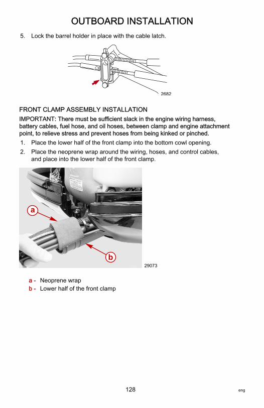
OUTBOARD INSTALLATION
128 eng
5. Lock the barrel holder in place with the cable latch.
2682
FRONT CLAMP ASSEMBLY INSTALLATIONIMPORTANT: There must be sufficient slack in the engine wiring harness,battery cables, fuel hose, and oil hoses, between clamp and engine attachmentpoint, to relieve stress and prevent hoses from being kinked or pinched.1. Place the lower half of the front clamp into the bottom cowl opening.2. Place the neoprene wrap around the wiring, hoses, and control cables,
and place into the lower half of the front clamp.
a - Neoprene wrapb - Lower half of the front clamp
a
b29073

OUTBOARD INSTALLATION
eng 129
3. Join the top half of the front clamp with the bottom half. Secure bothhalves together with cables ties.
a - Top half of the front clampb - Cable ties
4. Secure the front clamp into the bottom cowl with the retainer and twoscrews.
5. Install the cowl seal.
a - Retainer
a
b 29074
a
29075

OUTBOARD INSTALLATION
130 eng
Oil Injection Set‑Up
FILLING OIL SYSTEM1. Fill the remote oil tank with the recommended oil listed in the Operation
and Maintenance Manual. Tighten the fill cap.
a - Fill cap
2. Remove the cap and fill the engine oil tank with oil. Install the fill cap.
a - Engine oil tankb - Fill cap
a
2683
a
b
7745

OUTBOARD INSTALLATION
eng 131
PRIMING OIL INJECTION PUMPBefore starting the engine for the first time, prime the oil injection pump.Priming will remove any air that may be in the pump, oil supply hose, or internalpassages.
a - Oil supply hoseb - Oil injection pump
IMPORTANT: Fill the engine fuel system with fuel before priming the oilinjection pump. Otherwise, the fuel pump will run without fuel during the primingprocess and may be damaged.1. Fill the fuel system.
a. Connect fuel hose.b. Fill the fuel system by squeezing the primer bulb.c. Position the fuel line primer bulb so the arrow on the side of the bulb is
pointing up. Squeeze the fuel line primer bulb until it feels firm.
27348
3768
ba

OUTBOARD INSTALLATION
132 eng
d. Turn the ignition key switch to the "ON" position for three seconds.This operates the electric fuel pump.
26846
e. Turn the ignition key switch back to the "OFF" position, and squeezethe primer bulb again until it feels firm.
f. Turn the ignition key switch to the "ON" position again for threeseconds.
g. Continue this procedure until the fuel primer bulb stays firm.2. Turn the ignition key switch to the "ON" position.3. Within the first 10 seconds after the key switch has been turned on, move
the remote control handle from neutral into forward. This will automaticallystart the priming process.
PURGING AIR FROM THE ENGINE OIL TANK1. Loosen the fill cap on the engine oil tank.2. Start the engine.3. Operate the engine until all the air has vented out and oil starts to flow out
of the tank.4. Tighten the fill cap.
Trim In Pin
! WARNINGOperating the boat at high speeds with the outboard trimmed too far undercan create excessive bow steer, resulting in the operator losing control of theboat. Install the trim limit pin in a position that prevents excessive trim underand operate the boat in a safe manner.
Some boats, particularly some bass boats, are built with a greater than normaltransom angle, which will allow the outboard to be trimmed further in or under.This greater trim under capability is desirable to improve acceleration, reducethe angle and time spent in a bow high boat during planing off, and in somecases, may be necessary to plane off a boat with aft livewells, given the varietyof available propellers and height range of engine installations.

OUTBOARD INSTALLATION
eng 133
However, once on plane, the engine should be trimmed to a more intermediateposition to avoid a bow‑down planing condition called plowing. Plowing cancause bow steering or oversteering and inefficiently consumes horsepower.
a - Tilt pin (not included with engine)
Stainless Steel Tilt Pin 17‑49930A 1
2749
Limits the down trim angle of the powertrim equipped engines, or aids indetermining the trim out angle onnon‑power trim engines.
The owner may decide to limit the trim in. This can be accomplished bypurchasing a stainless steel tilt pin from your dealer and insert it in whateveradjustment hole in the transom brackets is desired. A nonstainless steelshipping bolt should not be used in this application other than on a temporarybasis.
2688
a

MAINTENANCE LOG
134 eng
Maintenance LogRecord all maintenance performed on your outboard here. Be sure to save allwork orders and receipts.
Date Maintenance Performed Engine Hours