925965 pure enclosed ins 0117 - dormaproducts.dorma.com/content/download/42626/480765/925965...
TRANSCRIPT

Installation instructions
For Framed Pivoting Door Systems
DORMA
INTERIOR
—PURE ENCLOSE® 22CH/20CH
Glass Wall Systems

DORMA USA, Inc. Dorma Drive, Drawer AC Toll-Free: 800-523-8483 Website: www.dorma.com
925965 01/17 Reamstown, PA 17567 Fax: 800-274-9724 Subject to change without notice
TABLE OF CONTENTS—
Overall view
PURE Enclose® 3
Technical specifi cations
General
Mounting
Maintenance 3
Pre-installation measurements and tips
Door frame alignment
Daylight opening 4
INSTALLATION INSTRUCTIONS
OPTION 1 - PURE Enclose® System: Concealed overlead closer (RTS88) & Floor Pivot (355.6)
Vertical sidelite post 'A' and vertical jamb post 'E' 5
Sidelite header assembly 'B' 6
Sidelite sill assembly 'C' 7
Install header/top pivot 'F' (RTS88) 8
Mounting bracket and I-post mounting bracket 9
Install sidelite glass panel 10
Vertical strike post/I-post 'D' 11
Install top (PT22) and bottom (PT10) patch fi ttings 12
Install fl oor pivot 'H' (355.6) 13
Install glass door panel 14
OPTION 2 - PURE Enclose® System: Free Swing: Top pivot (PT21 walking beam pivot) & Floor pivot (355.6)
Vertical sidelite post 'A' and vertical jamb post 'E' 15
Sidelite head assembly 'B' 16
Sidelite sill assembly 'C' 17
Install top pivot (PT21) 18
Mounting bracket and I-post mounting bracket 19
Install sidelite glass panel 20
Vertical strike post/I-post 'D' 21
Install top (PT20) and bottom (PT10) patch fi ttings 22
Install fl oor pivot 'H' (355.6) 23
Install glass door panel 24

DORMA USA, Inc. Dorma Drive, Drawer AC Toll-Free: 800-523-8483 Website: www.dorma.com
925965 01/17 Reamstown, PA 17567 Fax: 800-274-9724 Subject to change without notice
PURE ENCLOSE®
—
3
Overall view
A. Vertical sidelite post
B. Sidelite header assembly
C. Sidelite sill extrusion
assembly
D. Vertical strike post/I-post
E. Vertical jamb post
F. Header with closer/pivot
G. Patch fittings
H. Floor closer/floor pivot
I. Sidelite glass panel
J. Pivot door glass panel
A
BF
D
H
JI
G
E
C
G
Important safety-related information for the mounting and use of DORMA glass hardware.
(Follow these instructions in addition to the mounting and operating instructions in order to avoid damage of product and damage to person or property.)
Important: This document is intended to inform users of safety-related information and the mounting and operation instructions.
General information
1. DORMA requires use of tempered laminate or monolithic
glass.
2. DORMA glass hardware is not suitable for application in
rooms where chemicals (e.g. chlorine) are used as indoor
swimming pools, saunas or salt-water pools.
3. Never move sliding panels faster than walking speed
and always stop the door manually before it reaches end
position.
4. Do not swing doors with excessive force. Install limiting
stop to prevent door from opening too far.
Mounting
1. Only properly qualified and specially trained staff is
authorized to mount DORMA glass hardware.
2. Never use glass with conchoidal fractures and/or
damaged edges.
3. Due to crushing hazards and possible injury caused
by breakage of glass during mounting, corresponding
protective clothing (especially gloves and protective
goggles) is required.
4. Clean clamping area with alcohol-based standard
commercial cleaning agent before mounting the glass
hardware.
5. Never clamp metal glass fitting hardware directly to glass
surface.
6. Never use clamping roller carriers on self-cleaning
coatings.
7. When adjusting glass elements, always stick to the
required clearance for the respective hardware. Adjust
clearance so glass does not come in contact with any
hard surfaces such as glass, metal or concrete.
8. Do not use excessive force when installing the glass
(avoid over tightening screws).
Maintenance Check glass hardware at regular intervals for proper
positioning and smooth operation and correct
adjustment. High traffic door systems require inspection
by properly qualified staff (specialized companies or
installation firms). Immediately replace damaged glass
elements (no glass flaking and/or conchoidal fractures)!
Only use suitable cleaning and care products to clean
the surfaces.
Technical specifications
PURE Enclose®
DORMA USA, Inc. Dorma Drive, Drawer AC Toll-Free: 800-523-8483 Website: www.dorma.com
925965 01/17 Reamstown, PA 17567 Fax: 800-274-9724 Subject to change without notice
PURE ENCLOSE®
—
4
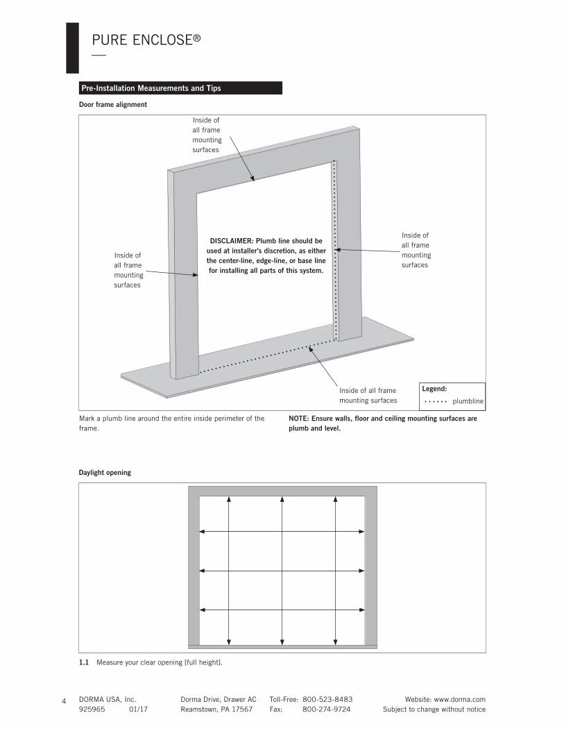
Pre-Installation Measurements and Tips
Door frame alignment
Mark a plumb line around the entire inside perimeter of the
frame.
NOTE: Ensure walls, floor and ceiling mounting surfaces are plumb and level.
1.1 Measure your clear opening [full height].
Daylight opening
Legend:
plumbline
Inside of
all frame
mounting
surfaces
Inside of
all frame
mounting
surfaces
Inside of
all frame
mounting
surfaces
Inside of all frame
mounting surfaces
DISCLAIMER: Plumb line should be used at installer's discretion, as either the center-line, edge-line, or base line for installing all parts of this system.

DORMA USA, Inc. Dorma Drive, Drawer AC Toll-Free: 800-523-8483 Website: www.dorma.com
925965 01/17 Reamstown, PA 17567 Fax: 800-274-9724 Subject to change without notice
PURE ENCLOSE®
—
5
Vertical sidelite post 'A' & Vertical jamb post 'E'
PIVOT DOOR
SIDE LITE
E
FB
A D
C H
Vertical sidelite
extrusion
Vertical sidelite
glazing pocket
Vertical jamb
extrusion
Vertical jamb flat
panel cover
1
1.1 Measure and cut channel at full height.
1.2 Disassemble post parts.
1.3 Pre-drill holes.
NOTE: Offset screws from glazing pocket.
NOTE: Add fill foam where necessary.
1.4 Align channel with plumb line.
1.5 Secure channel to frame.
Vertical sidelite post 'A':
1.6 Trim Dri-fit® gaskets.
1.7 Snap glazing pocket into extrusion.
Vertical jamb post 'E':
1.8 Snap on flat panel cover.
Top side of extrusion tube(s).
Fill foam: Keep close to edge of extrusion.
Vertical
sidelite
extrusion
Vertical
sidelite
glazing
Vertical
jamb
extrusion
Vertical jamb flat
panel cover
Offset
screws
from
glazing
OPTION 1 - PURE Enclose® System:Concealed Overhead Closer (RTS88) & Floor Pivot (355.6)
Fill foam

DORMA USA, Inc. Dorma Drive, Drawer AC Toll-Free: 800-523-8483 Website: www.dorma.com
925965 01/17 Reamstown, PA 17567 Fax: 800-274-9724 Subject to change without notice
PURE ENCLOSE®
—
6
2.1 Measure and cut sidelite header:
Sidelite header length = (extrusion to extrusion) - (clear opening + 1-3/4")
Example for a 36" wide door: Sidelite header length = (Extrusion to Extrustion) - 37-3/4"
2.2 Disassemble sidelite header parts.
2.3 Pre-drill holes.
OPTION 1 - Concealed Overhead Closer & Floor Pivot
NOTE: Offset screws from glazing pocket.
NOTE: Add fill foam where necessary.
2.4 Align sidelite header extrusion with plumb line.
2.5 Secure sidelite header to frame.
2.6 Trim Dri-fit gaskets.
2.7 Snap glazing pocket into extrusion.
Sidelite header
extrusion
Sidelite header
glazing pocket
PIVOT DOOR
SIDE LITE
E
FB
A D
C H
2
Top side of extrusion tube(s).
Fill foam: Keep close to edge of extrusion.
Sidelite header
extrusion
Offset
screws
from
glazing
37-3/4"[959]
Extrusion to Extrusion
Example only:
Sidelite header assembly 'B'
Fill foam

DORMA USA, Inc. Dorma Drive, Drawer AC Toll-Free: 800-523-8483 Website: www.dorma.com
925965 01/17 Reamstown, PA 17567 Fax: 800-274-9724 Subject to change without notice
PURE ENCLOSE®
—
7
3.1 Measure and cut sidelite sill extrusion.
Sill extrusion length = (extrusion to extrusion) - (clear opening + 1-3/4")
Example for a 36" wide door: Sill extrusion length = (Extrusion to Extrustion) - 37-3/4"
3.2 Disassemble sidelite sill extrusion parts.
3.3 Pre-drill holes.
NOTE: Offset screws from glazing pocket.
NOTE: Add fill foam where necessary.
3.4 Align sidelite bottom extrusion with plumb line.
3.5 Secure bottom extrusion to frame.
3.6 Snap glazing pocket into extrusion.
3.7 Trim Dri-fit gaskets.
3.8 Slide setting blocks into glazing pocket.
NOTE: If using tempered laminated glass, remove one gasket.
Sidelite sill assembly 'C'
PIVOT DOOR
SIDE LITE
E
FB
A D
C H
Sidelite bottom
extrusionSidelite bottom
glazing pocket
3
Top side of extrusion tube(s).
Fill foam: Keep close to edge of extrusion.
Sidelite bottom
extrusion
37-3/4"[959]
Example only:
OPTION 1 - Concealed Overhead Closer & Floor Pivot
Fill foam

DORMA USA, Inc. Dorma Drive, Drawer AC Toll-Free: 800-523-8483 Website: www.dorma.com
925965 01/17 Reamstown, PA 17567 Fax: 800-274-9724 Subject to change without notice
PURE ENCLOSE®
—
8
Install header/top pivot 'F' (RTS88)
(consult DORMA for other options)
PIVOT DOOR
SIDE LITE
E
FB
A D
C H
Header
4
4.1 Remove cover and closer from RTS header tube and pre-
drill holes for installation. See image for hole locations.
4.2 Apply fill foam if necessary.
4.3 Secure header using appropriate fasteners.
NOTE: Always ensure the proper fastener and adequate number of fixing points for your specific field conditions.
4.4 Secure closer inside header tube using included
fasteners.
NOTE: Ensure closer is plumb and level.
NOTE: Secure mounting screws to header prior to securing it to overhead structure.
Inside of header tube (with RTS88)
Top of header tube (with RTS88)
Fill foam:
Keep close
to end of
header
Header
tube
RTS88
4"
[102]
OPTION 1 - Concealed Overhead Closer & Floor Pivot

DORMA USA, Inc. Dorma Drive, Drawer AC Toll-Free: 800-523-8483 Website: www.dorma.com
925965 01/17 Reamstown, PA 17567 Fax: 800-274-9724 Subject to change without notice
PURE ENCLOSE®
—
9
5.1 Disassemble I-post.
5.2 Measure and cut post at full height.
5.3 Trim Dri-fit gaskets.
5.4 Align and plumb I-post in place.
5.5 Align mounting bracket and I-post bottom bracket to
strike-side of I-post. See Figure A & B above for proper
orientation.
5.6 Secure brackets to I-post ONLY with self-tapping screws,
provided.
5.7 Pre-drill holes through:
Mounting bracket into header
I-post bottom bracket into floor mounting surface.
5.8 Remove I-post [with brackets attached]. (To be installed
permanently in later step.)
Mounting bracket and I-post mounting bracket
PIVOT DOOR
SIDE LITE
E
FB
A D
C H
I-post
5
Mounting
bracket
Header
extrusion
I-post
bottom
bracket
Mounting bracket
I-post bottom bracket
Wider side against header.
Wider side against I-post.
I-post
Header
Figure A
Figure B
Floor
mounting
surface
OPTION 1 - Concealed Overhead Closer & Floor Pivot

DORMA USA, Inc. Dorma Drive, Drawer AC Toll-Free: 800-523-8483 Website: www.dorma.com
925965 01/17 Reamstown, PA 17567 Fax: 800-274-9724 Subject to change without notice
PURE ENCLOSE®
—
10
6.1 Spray inside of each extrusion with glass cleaner:
Sidelite header
Vertical sidelite post
Sidelite sill extrusion
6.2 Lift glass into sidelite header and down into sill
extrusion.
6.3 Slide glass into vertical sidelite post.
NOTE: If using tempered laminated glass, gently press glass
panel against gasket and dispense silicone along full length of
non-gasket side of sill extrusion.
Install sidelite glass panel
PIVOT DOOR
SIDE LITE
E
FB
A D
C HSidelite
glass
Sidelite
header
Vertical
sidelite
post
Sidelite
sill
extrusion
6
OPTION 1 - Concealed Overhead Closer & Floor Pivot

DORMA USA, Inc. Dorma Drive, Drawer AC Toll-Free: 800-523-8483 Website: www.dorma.com
925965 01/17 Reamstown, PA 17567 Fax: 800-274-9724 Subject to change without notice
PURE ENCLOSE®
—
11
7.1 Snap glazing pocket into I-post.
7.2 Trim Dri-fit gaskets.
7.3 Spray Dri-fit gaskets for ease of installing onto glass
sidelite.
7.4 Secure I-post bottom bracket to floor surface, with
appropriate screws and anchors for the specific
application.
7.5 Secure mounting bracket into header extrusion.
7.6 Snap on I-post strike/flat cover.
7.7 Snap cover cap and header flat cover cap into place.
Vertical strike post/I-post 'D'
PIVOT DOOR
SIDE LITE
E
FB
A D
C H
I-post
I-post
bottom
bracket
Mounting
bracketHeader
extrusion
Flat
cover
Cover
cap
7
I-post strike/flat
cover
Sill mounting
bracket
OPTION 1 - Concealed Overhead Closer & Floor Pivot

DORMA USA, Inc. Dorma Drive, Drawer AC Toll-Free: 800-523-8483 Website: www.dorma.com
925965 01/17 Reamstown, PA 17567 Fax: 800-274-9724 Subject to change without notice
PURE ENCLOSE®
—
12
8.1 Completely separate patch fitting parts.
Disgard spacer blocks.
Remove backing tape from gaskets.
8.2 Secure gasket to inside of each patch fitting.
8.3 Place rubber bushing inside hole cut-out in glass panel.
Install top (PT22) and bottom (PT10) patch fittings (consult Dorma for other options)
Patch
fitting
covers Patch
fittingsPatch
fitting
gaskets
Top/
bottom
insert
Rubber
bushing
Patch fitting screws:
M6x27 FH screw
Rubber
bushing
Install patch fittings
Install inserts
Inserts screws:
M6x20 FH screw
Example: PT22 355.41
insert
Example: PT10 319.1
insert8
8.4
8.6
Secure patch fittings:
8.4 Properly align and level patch fitting on door.
8.5 Secure with included fasteners through glass.
PT10/PT22 fittings: Use an 5mm hex key and 11 ft lbs
(15Nm) of force.
Secure patch fitting inserts:
8.6 Install inserts into patch fittings.
8.7 Secure insert with included fasteners, alternating while
tightening.
PT22 insert: Use an 5 mm hex key and 11 ft lbs (15Nm)
of force. DO NOT ATTACH BACKER PLATE YET.
PT10 insert: Use an 5 mm hex key and 8 ft lbs (12Nm)
of force.
NOTE: Ensure center line of pivot is 2-5/8" from edge of patch fitting.
Hex key size:PT10/PT22 = 5mm
Torque value:PT10/PT22 ftg = 11ft lbs
[15Nm]
PT10 insert = 8ft lbs
[12Nm]
OPTION 1 - Concealed Overhead Closer & Floor Pivot

DORMA USA, Inc. Dorma Drive, Drawer AC Toll-Free: 800-523-8483 Website: www.dorma.com
925965 01/17 Reamstown, PA 17567 Fax: 800-274-9724 Subject to change without notice
PURE ENCLOSE®
—
13
9.1 Using an appropriate plumbing tool, align the floor pivot
with the location of the RTS spindle.
9.2 Bore a 1" [25mm] diameter hole 3/8" [10mm] deep.
Install floor pivot 'H' (355.6 adjustable floor pivot)(consult Dorma for other options)
9.3 Secure floor pivot to floor using appropriate screws and
anchors for the specific application.
PIVOT DOOR
SIDE LITE
E
FB
A D
C HExample: Floor
pivot (355.6)
9
OPTION 1: Concealed Overhead Closer & Floor Pivot

DORMA USA, Inc. Dorma Drive, Drawer AC Toll-Free: 800-523-8483 Website: www.dorma.com
925965 01/17 Reamstown, PA 17567 Fax: 800-274-9724 Subject to change without notice
PURE ENCLOSE®
—
14
Install door onto 355.6 floor pivot:
10.1 Place bottom patch fitting onto floor pivot spindle.
OPTION 1: Install door into concealed overhead closer (non-hold open):(For ease of loading door.)
10.2 Close both valves on RTS88 closer.
10.3 Using a wrench, rotate spindle towards swing of the door
(fully open) until it stops.
10.4 Tip glass up and onto header spindle.
NOTE: Ensure door is in proper orientation.
10.5 Secure PT22 (355.41) backer plate with provided
fasteners; first tighten screws snug against spindle, then
fully tighten alternating each.
Use a 6mm hex key and 15 ft lbs [20Nm] force.
Ensure backer plate is flush against spindle.
Install glass door panel
PT22 355.41 insert backer plate
Backer plate screws:
M8x27 FH screw
Top/Bottom patch
fitting covers
Floor pivot (355.6)
Floor pivot set screw
10
RTS88
closer valves
Tools needed:355.6 pivot = 15/16" wrench
355.6 pivot = 2mm hex key
Backer plate = 6mm hex key
Torque value:PT22 backer plate =
15ft lbs [20Nm]
SpindleRTS88
Adjust door height:10.6 Adjust floor pivot spindle to adjust for door height.
Spin adjustable floor pivot (355.6) spindle up or down
until, using 15/16" wrench, until correct door height is
met.
Tighten set screw, using 2mm hex key, to secure spindle
in position.
NOTE: Ensure set screw is fully engaged with spindle. If set screw is tightened properly, spindle should NOT rotate.
Secure floor pivot cover with included fastener.
10.7 Snap covers onto both sides of patch fittings.
OPTION 2: Install door into concealed overhead closer (hold open):(For ease of loading door.)
10.2 Close both valves on RTS88 closer.
10.3 Open door to preset hold open position.
10.4 Tip glass up and onto header spindle.
10.5 Secure PT22 (355.41) backer plate with provided
fasteners; first tighten screws snug against spindle, then
fully tighten alternating each.
Use a 6mm hex key and 15 ft lbs [20Nm] force.
Ensure backer plate is flush against spindle.
OPTION 1: Concealed Overhead Closer & Floor Pivot

DORMA USA, Inc. Dorma Drive, Drawer AC Toll-Free: 800-523-8483 Website: www.dorma.com
925965 01/17 Reamstown, PA 17567 Fax: 800-274-9724 Subject to change without notice
PURE ENCLOSE®
—
15
Vertical sidelite post 'A' & Vertical jamb post 'E'
PIVOT DOOR
SIDE LITE
E
FB
A D
C H
Vertical sidelite
extrusion
Vertical sidelite
glazing pocket
Vertical jamb
extrusion
Vertical jamb flat
panel cover
1
1.1 Measure and cut channel at full height.
1.2 Disassemble post parts.
1.3 Pre-drill holes.
NOTE: Offset screws from glazing pocket.
NOTE: Add fill foam where necessary.
1.4 Align channel with plumb line.
1.5 Secure channel to frame.
Vertical sidelite post 'A':
1.6 Trim Dri-fit® gaskets.
1.7 Snap glazing pocket into extrusion.
Vertical jamb post 'E':
1.8 Snap on flat panel cover.
Top side of extrusion tube(s).
Fill foam: Keep close to edge of extrusion.
Vertical
sidelite
extrusion
Vertical
sidelite
glazing
Vertical
jamb
extrusion
Vertical jamb flat
panel cover
Offset
screws
from
glazing
OPTION 2 - PURE Enclose® System: Free Swing: Top Pivot (PT21 Walking Beam Pivot) & Floor Pivot (355.6)
Fill foam

DORMA USA, Inc. Dorma Drive, Drawer AC Toll-Free: 800-523-8483 Website: www.dorma.com
925965 01/17 Reamstown, PA 17567 Fax: 800-274-9724 Subject to change without notice
PURE ENCLOSE®
—
16
2.1 Measure and cut sidelite header:
Sidelite header length = (extrusion to extrusion) - (clear opening + 1-3/4")
Example for a 36" wide door: Sidelite header length = (Extrusion to Extrustion) - 37-3/4"
2.2 Disassemble sidelite header parts.
2.3 Pre-drill holes.
OPTION 2 - Free Swing: Top Pivot & Floor Pivot
NOTE: Offset screws from glazing pocket.
NOTE: Add fill foam where necessary.
2.4 Align sidelite header extrusion with plumb line.
2.5 Secure sidelite header to frame.
2.6 Trim Dri-fit gaskets.
2.7 Snap glazing pocket into extrusion.
Sidelite header
extrusion
Sidelite header
glazing pocket
PIVOT DOOR
SIDE LITE
E
FB
A D
C H
2
Top side of extrusion tube(s).
Fill foam: Keep close to edge of extrusion.
Sidelite header
extrusion
Offset
screws
from
glazing
37-3/4"[959]
Extrusion to Extrusion
Example only:
Sidelite header assembly 'B'
Fill foam

DORMA USA, Inc. Dorma Drive, Drawer AC Toll-Free: 800-523-8483 Website: www.dorma.com
925965 01/17 Reamstown, PA 17567 Fax: 800-274-9724 Subject to change without notice
PURE ENCLOSE®
—
17
3.1 Measure and cut sidelite sill extrusion.
Sill extrusion length = (extrusion to extrusion) - (clear opening + 1-3/4")
Example for a 36" wide door: Sill extrusion length = (Extrusion to Extrustion) - 37-3/4"
3.2 Disassemble sidelite sill extrusion parts.
3.3 Pre-drill holes.
NOTE: Offset screws from glazing pocket.
NOTE: Add fill foam where necessary.
3.4 Align sidelite bottom extrusion with plumb line.
3.5 Secure bottom extrusion to frame.
3.6 Snap glazing pocket into extrusion.
3.7 Trim Dri-fit gaskets.
3.8 Slide setting blocks into glazing pocket.
NOTE: If using tempered laminated glass, remove one gasket.
Sidelite sill assembly 'C'
PIVOT DOOR
SIDE LITE
E
FB
A D
C H
Sidelite bottom
extrusionSidelite bottom
glazing pocket
3
Top side of extrusion tube(s).
Fill foam: Keep close to edge of extrusion.
Sidelite bottom
extrusion
37-3/4"[959]
Example only:
OPTION 2 - Free Swing: Top Pivot & Floor Pivot
Fill foam

DORMA USA, Inc. Dorma Drive, Drawer AC Toll-Free: 800-523-8483 Website: www.dorma.com
925965 01/17 Reamstown, PA 17567 Fax: 800-274-9724 Subject to change without notice
PURE ENCLOSE®
—
18
OPTION 2 - Free Swing: Top Pivot & Floor Pivot
Install top pivot (PT21)
(consult DORMA for other options)
4.1 Remove cover from header tube and pre-drill holes for
installation. See image for hole locations.
4.2 Apply fill foam if necessary.
4.3 Secure header using appropriate fasteners.
NOTE: Always ensure the proper fastener and adequate number of fixing points for your specific field conditions.
4.4 Raise walk ing beam pivot spindle up completely by
rotating spindle adjustment screw.
NOTE: Ensure closer is plumb and level.
4
Inside of header tube (with PT21 walking beam pivot)
Top of header tube (with PT21 walking beam pivot)
PT21
Spindle
adjustment screw Spindle
Fill foam:
Keep close
to edge of
header.
PIVOT DOOR
SIDE LITE
E
FB
A D
C H
PT21

DORMA USA, Inc. Dorma Drive, Drawer AC Toll-Free: 800-523-8483 Website: www.dorma.com
925965 01/17 Reamstown, PA 17567 Fax: 800-274-9724 Subject to change without notice
PURE ENCLOSE®
—
19
5.1 Disassemble I-post.
5.2 Measure and cut post at full height.
5.3 Trim Dri-fit gaskets.
5.4 Align and plumb I-post in place.
5.5 Align mounting bracket and I-post bottom bracket to
strike-side of I-post. See Figure A & B above for proper
orientation.
5.6 Secure brackets to I-post ONLY with self-tapping screws,
provided.
5.7 Pre-drill holes through:
Mounting bracket into header
I-post bottom bracket into floor mounting surface.
5.8 Remove I-post [with brackets attached]. (To be installed
permanently in later step.)
Mounting bracket and I-post mounting bracket
PIVOT DOOR
SIDE LITE
E
FB
A D
C H
I-post
5
Mounting
bracket
Header
extrusion
I-post
bottom
bracket
Mounting bracket
I-post bottom bracket
Wider side against header.
Wider side against I-post.
I-post
Header
Figure A
Figure B
Floor
mounting
surface
OPTION 2 - Free Swing: Top Pivot & Floor Pivot

DORMA USA, Inc. Dorma Drive, Drawer AC Toll-Free: 800-523-8483 Website: www.dorma.com
925965 01/17 Reamstown, PA 17567 Fax: 800-274-9724 Subject to change without notice
PURE ENCLOSE®
—
20
6.1 Spray inside of each extrusion with glass cleaner:
Sidelite header
Vertical sidelite post
Sidelite sill extrusion
6.2 Lift glass into sidelite header and down into sill
extrusion.
6.3 Slide glass into vertical sidelite post.
NOTE: If using tempered laminated glass, gently press glass
panel against gasket and dispense silicone along full length of
non-gasket side of sill extrusion.
Install sidelite glass panel
PIVOT DOOR
SIDE LITE
E
FB
A D
C HSidelite
glass
Sidelite
header
Vertical
sidelite
post
Sidelite
sill
extrusion
6
OPTION 2 - Free Swing: Top Pivot & Floor Pivot

DORMA USA, Inc. Dorma Drive, Drawer AC Toll-Free: 800-523-8483 Website: www.dorma.com
925965 01/17 Reamstown, PA 17567 Fax: 800-274-9724 Subject to change without notice
PURE ENCLOSE®
—
21
7.1 Snap glazing pocket into I-post.
7.2 Trim Dri-fit gaskets.
7.3 Spray Dri-fit gaskets for ease of installing onto glass
sidelite.
7.4 Secure I-post bottom bracket to floor surface, with
appropriate screws and anchors forthe specific
application.
7.5 Secure mounting bracket into header extrusion.
7.6 Snap on I-post strike/flat cover.
7.7 Snap cover cap and header flat cover cap into place.
Vertical strike post/I-post 'D'
PIVOT DOOR
SIDE LITE
E
FB
A D
C H
I-post
I-post
bottom
bracket
Mounting
bracketHeader
extrusion
Flat
cover
Cover
cap
7
I-post strike/flat
cover
Sill mounting
bracket
OPTION 2 - Free Swing: Top Pivot & Floor Pivot

DORMA USA, Inc. Dorma Drive, Drawer AC Toll-Free: 800-523-8483 Website: www.dorma.com
925965 01/17 Reamstown, PA 17567 Fax: 800-274-9724 Subject to change without notice
PURE ENCLOSE®
—
22
OPTION 2: Free Swing: Top Pivot & Floor PivotInstall top (PT20) and bottom (PT10) patch fittings (consult DORMA for other options)
8.1 Completely separate patch fitting parts.
Throw away spacer blocks.
Remove backing tape from gaskets.
8.2 Secure gasket to inside of each patch fitting.
8.3 Place rubber bushing inside hole cut-out in glass panel.
Patch
fitting
covers Patch
fittingsPatch
fitting
gaskets
Rubber
bushing
Patch fitting screws:
M6x27 FH screw
Rubber
bushing
Install patch fittings
Install inserts
319.1 insert screws:
M6x20 FH screw
PT20 319.2 insert
8
NOTE: Ensure center line of pivot is 2-5/8" from edge of patch fitting.
319.2 insert screws:
M6x15 screw
8.4
8.6
NOTE: Fasteners toward inside of glass
PT10 319.1 insert
Hex key size:PT10/PT20 = 5mm
Torque value:PT10/PT20 ftg = 11ft lbs
[15Nm]
PT10 insert = 8ft lbs
[12Nm]
Secure patch fitting inserts:8.6 Install inserts into patch fittings.
8.7 Secure insert with included fasteners, alternating while
tightening.
PT20 insert: Use a 5 mm hex key and 11 ft lbs (15Nm) of
force.
PT10 insert: Use a 5 mm hex key and 8 ft lbs (12Nm) of
force.
Secure patch fittings:
8.4 Properly align and level patch fitting on door.
8.5 Secure with included fasteners through glass.
PT10/PT20 fittings: Use a 5mm hex key and 11 ft lbs
(15Nm) of force.

DORMA USA, Inc. Dorma Drive, Drawer AC Toll-Free: 800-523-8483 Website: www.dorma.com
925965 01/17 Reamstown, PA 17567 Fax: 800-274-9724 Subject to change without notice
PURE ENCLOSE®
—
23
9.1 Using an appropriate plumbing tool, align the PT21
walking beam pivot spindle with the location of the
bottom pivot.
Install floor pivot 'H' (355.6 adjustable floor pivot)(consult Dorma for other options)
9.2 Bore a 1" [25mm] diameter hole 3/8" [10mm] deep.
9.3 Secure floor pivot to floor using appropriate screws and
anchors for the specific application.
PIVOT DOOR
SIDE LITE
E
FB
A D
C HExample: Floor
pivot (355.6)
9
OPTION 2: Free Swing: Top Pivot & Floor Pivot

DORMA USA, Inc. Dorma Drive, Drawer AC Toll-Free: 800-523-8483 Website: www.dorma.com
925965 01/17 Reamstown, PA 17567 Fax: 800-274-9724 Subject to change without notice
PURE ENCLOSE®
—
24
Install door onto 355.6 floor pivot:
10.1 Place bottom patch fitting onto floor pivot spindle.
Install door into top pivot (PT21 walking beam pivot):
10.2 Tip glass up vertically in line with pivot spindle.
10.3 Rotate PT21 pin down into patch fitting insert by
rotating the pin adjustment screw.
Install glass door panel
Top/Bottom patch
fitting covers
Floor pivot (355.6)
Floor pivot set screw
10
Tools needed:355.6 pivot = 15/16" wrench
355.6 pivot = 2mm hex key
Adjust door height:
10.4 Adjust floor pivot spindle to adjust for door height.
Spin adjustable floor pivot (355.6) spindle up or down,
using 15/16" wrench, until correct door height is met.
Tighten set screw, using 2mm hex key, to secure spindle
in position.
NOTE: Ensure set screw is fully engaged with spindle. If set screw is tightened properly, spindle should NOT rotate.
Secure floor pivot cover with included fastener.
10.5 Snap covers onto both sides of patch fittings.
OPTION 2: Free Swing: Top Pivot & Floor Pivot
PT21
Spindle adjustment
screw
Spindle
Floor pivot
(355.6)
Top pivot (PT21 walking
beam pivot)

9259
65
01
/2017,
Subje
ct
to c
hange w
ithout
notice
DORMA USA, INC.
DORMA DRIVE, DRAWER AC
REAMSTOWN, PA 17567
TOLL-FREE: 800-523-8483
FAX: 800-274-9724
WWW.DORMA.COM