92-27848 - defense technical information center · the hot gas is then expanded in the turbine...
TRANSCRIPT

ARL-PROP-TM-475 AR-006-677
AD'A256 320, JAL
DEPARTMENT OF DEFENCE
DEFENCE SCIENCE AND TECHNOLOGY ORGANISATION
AERONAUTICAL RESEARCH LABORATORY
MELBOURNE, VICTORIA
OCT12 3 1992
Propulsion Technical Memorandum 475
A PRELIMINARY INVESTIGATION INTO THEFEASIBILITY OF USING A SMALL TURBOJET TOPROPEL AN EXPENDABLE HOVERING DECOY
by
B. PARMINGTON
92-27848
Approved for public release
) COMMONWEALTH OF AUSTRALIA 1992
JUNE 1992
~ ~ ~

This work Is copyright. Apart from any fair dealing for the purpose ofstudy, rescarch, criticism or review, as permitted under the CopyrightAct, no part may be reproduced by any process without writtenpermission. Copyright is the responsibility of the Director Publishlngand Marketing, AGPS. Enquiries should be directed to the Manager,AGPS Press, Australian Government Publishing Servibe, GPO Box 84,CANBERRA ACT 2601.
'i

AR-006-677
DEPARTMENT OF DEFENCEDEFENCE SCIENCE AND TECHNOLOGY ORGANISATION
AERONAUTICAL RESEARCH LABORATORY
Propulsion Technical Memorandum 475
A PRELIMINARY INVESTIGATION INTO THEFEASIBILITY OF USING A SMALL TURBOJET TO
PROPEL AN EXPENDABLE HOVERING DECOY
by
B. PARMINGTON
SUMMARY
The of use of a turbojet engine to propel a hovering decoy has been investigated to determineits suitability for this role in terms of operating characteristics, vehiclelengine integrationand cost. The thrust and flight endurance were assumed to be 450 N and 5 minutes. As analternative to purchasing engines from manufacturers, the option of manufacturing such anengine in Australia using off the shelf automotive turbocharger components has beenexplored
The special characteristics of the turbojet are compared with those of a rocket and some ofthe broader design considerations needed to adapt the turbojet to this application arediscussed.
DSTOaAUSTRALIA
@ COMMONWEALTH OF AUSTRALIA 1992 I..vtr-r,'une[.
POSTAL ADDRESS: Director, Aeronautical Research Laboratory .506 Lorimer Street, Fishermens Bend 3207 " , t
Victoria Australia or t ,
9,-\

TABLE OF CONTENTS
PAGE NO
1. INTRODUCTION ................................... 1
2. HOVERING PERFORMANCE OF THE TURBOJET ANDSOLID FUEL ROCKET MOTOR ......................... 1
3. FEATURES OF AVAILABLE TURBOJETS .................. 23.1 Operation ..................................... .23.2 Lubrication . ................................... .23.3 Fuel Handling System ............................... 23.4 Cranking and Ignition ............................... 3
4. FEATURES OF THE ARL TURBOJET FOR LOCAL MANUFACTURE. 3
5. TURBOJET COST ESTIMATES ......................... .45.1 Overseas Procurement ............................... 55.2 Local Design and Manufacture ......................... 5
6. PROCUREMENT OPTIONS ............................. 5
7. TURBOJET/VEHICLE INTEGRATION ..................... 5
8. THRUST CONTROL AND MANOEUVRING ................. 6
9. STARTING THE TURBOJET ............................ 6
10. EFFECT OF LAUNCHING ACCELERATION ON THE TURBOJET .. 7
11. LAUNCHER CONFIGURATION ......................... 7
12. CONCLUSION .................................... 8
REFERENCES ......................................... 9
FIGURES 1-10
DISTRIBUTION
DOCUMENT CONTROL DATA
'A€

-1-
S1. INTRODUCTION
The current emphasis on increasing the pay load and/or flight duration of stand offweapons has encouraged the development of a whole new generation of small,expendable turbojets which are now being used in such applications as target drones,reconnaissance and surveillance, and cruise missiles.
The present investigation was undertaken as an element of a broader study of enablingtechnologies for an advanced hovering decoy, intended for a role that demands extendedflight time and/or pay load capability which may not be achievable with a solid fuelrocket engine.
In order to proceed with the investigation, in the absence of a firm vehicle specification, anumber of assumptions had to be made about the engine/vehicle performance. Theassumptions are:
1. Thrust required 450 N.
2. Full thrust will be achieved before the launch of the vehicle orimmediately it has left launcher so that it is available to lift the vehicle toits operating height and for manoeuvring.
3. The decoy will be launched from a tube using a mortar charge.
4. Thrust vectoring will be used for manoeuvring.
5. Hovering life approximately five minutes.
2. HOVERING PERFORMANCE OF THE TURBOJET AND SOLID FUELROCKET MOTOR
The advantages of the turbojet over the rocket motor are illustrated in Figs. 1 and 2(reproduced from Ref. 1), for a range of payloads and flight durations. This improvementis possible because the oxidant is not carried on-board and because a larger mass flow ofpropellant is exhausted at a lower nozzle discharge velocity, resulting in a betterpropulsive efficiency.
The fuel specific impulse of a small turbojet is typically in the range 22000 to 30000N/(kg/s), much higher than the solid fuel rocket which normally is about 2245 N/(kg/s)(Ref.2). In terms of specific fuel consunmption, the conventional measure of gas turbineperformance, typical figures for small turbojets and solid fuel rockets are 4x10"5 and4.5x10"4 kg/N.s respectively.
I,
'i

-2-
3. FEATURES OF AVAILABLE TURBOJETS
3.1 Operation
Figs 3, 4, 5 and 6 show schematically the layout and construction of four expendableturbojet engines developed by TELEDYNE and SUNDSTRAND of US and NOELPENNY TURBINES of UK.
All four engines use a single stage radial compressor coupled by a single shaft to a radialor axial turbine, the latter used by Teledyne. Rolling contact element bearings are used inall the engines to support the turbine and compressor wheels.
The air enters the compressor axially, which imparts to it kinetic energy, which isconverted to pressure energy by the radial diffuser. On leaving the diffuser the air entersthe combustor at a pressure of 3.5 to 4.5 atmospheres where its temperature is raised toabout 1000 degrees Celsius at constant pressure. The hot gas is then expanded in theturbine which removes the energy required to drive the compressor. The residual pressureenergy in the combustion gas is converted to kinetic energy in the exhaust nozzle topropel the vehicle.
It will be noted that each engine has a fixed rated thrust. Where this does not preciselymatch the vehicle weight, there is scope for uprating or derating the engines. In the caseof the former, this may or may not entail reduction in operating life.
3.2 Lubrication
The a.ppropriate method of lubrication of bearings depends on their location in the bodyof the engine, on the load they carry, the temperature they experience, the speed ofrotation mid the length of service. Teledyne and Noel Penny have used grease in theirdesigns. Sundstrand have used oil mist lubrication because of the high shaft speed. Of thetwo methods grease lubrication is the simpler because it dispenses with the scavengepump, shaft seals, filters, oil tanks and coolers normally required with a circulating oillubricating system, thereby reducing costs and complexity. Oil mist lubrication is a totalloss system in which the oil supplied to the bearings is drawn into the combustor andburned. This method requires an oil tank and oil pump or pressurised oil tank on board.
3.3 Fuel Handling System
In current turbojets used in unmanned vehicle application, the fuel management system isusually electronically controlled by a computer mounted on the air frame or on theengine. A simple fuel handling system is comprisd of a fuel pump, an electronicallycontrolled modulating valve to meter fuel flow to the engine, a shut off valve and,depending on the fuel pump delivery pressure and the method of fuelling the coLmbustionchamber, a pressure regulating valve. The fuel pump may be coupled to the shaft of theengine or be driven by an electric motor. Driving the fuel pump electrically has theadvantage that it can be used to meter the fuel to the combustor by modulating its speedin response to engine demand. These and other options are discussed in more detail inRef.3.
I

-3-
3.4 Cranking And Ignition
Three cranking methods are in general use: air impingement, windmilling andpyrotechnic cartridge.
Air impingement is used for ground starts and is achieved by injecting high pressure air at550 to 700 kPa into the compressor by means of a nozzle in the compressor housing.When the proper rotational speed has been reached, the fuel is ignited using a high energyigniter plug. During this phase of operation, fuel to the turbojet may be supplied from theon-board fuel tank, or by fuel lines coupled to an external source by quick releasecouplings. During launch, the external fuel lines are released and the turbojet is suppliedfrom the fuel tank on board.
Windmill start is used when the unmanned vehicle is launched by rocket or from anairborne platform such as a jet aircraft. Air is forced into the intake of the engine causingthe engine to windmill. Ignition of the fuel is as above.
Pyrotechnic cartridge start is a "one shot" high energy solid grain pyrotechnic cartridge,which is discharged through the turbine to crank the engine and ignite the fuel airmixture. Fig.5 and 6 illustrate the location of the pyrotechnic cartridge on the Noel Pennyturbojets.
I
4. FEATURES OF THE ARL TURBOJET FOR LOCAL MANUFACTURE
The engines described, although intended for use in expendable vehicles, are generallydesigned for a longer working life than is required for this application, and are built tostandards entailing costs which arguably could be reduced.
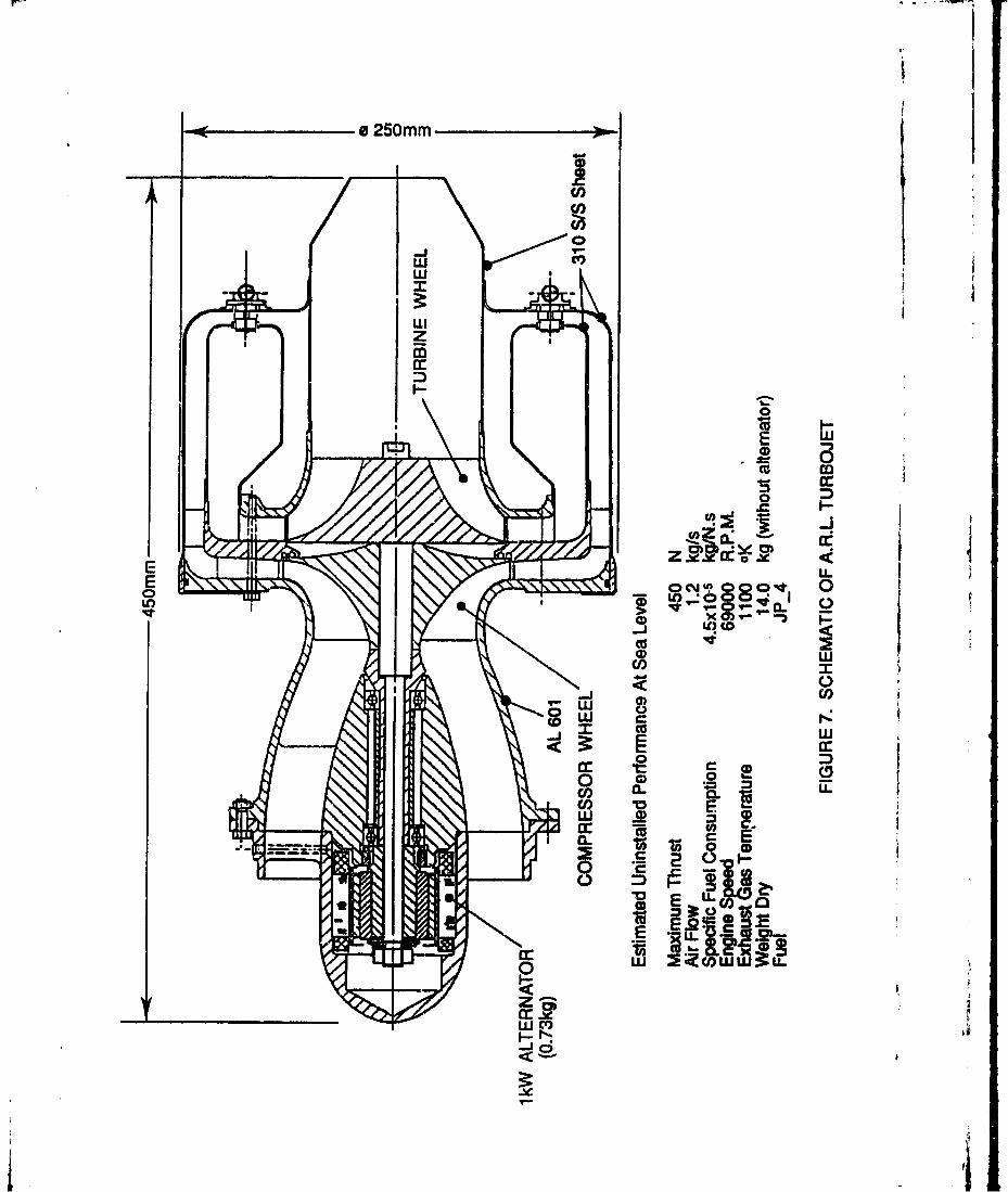
The feasibility of minimising engine costs, by methods including the use of off-the-shelfautomotive turbocharger components in an engine which could be manufactured inAustralia, has been investigated in a design study. Fig.7 is a preliminary design lay-outused to obtain the cost estimates. This geometry was selected because it permittedminimum outside diameter, low number of parts, low weight and low production costs.
The engine has been designed around the Garrett-AiResearch industrial turbochargercompressor and turbine wheels, part numbers L497326-4 (408554 DUP 4: 1LE) trim "P"
and 408649-3 "G" trim 1.7 A/R (Ref.4). These components, mass produced forautomotive use, were selected by Garrett-AiResearch for use in an expendable turbojetdesign of their own, the ETJ131 of 445N thrust, which underwent preliminarydevelopment some years ago (Ref.5). The integration of the turbocharger components,other than the rotors, into the ARL design was considered, but it was found to beimpractical because of the weight and size penalty these components would impose.
I'

-4-
The compressor and turbine are of a radial flow type, assembled back to back andsupported by rolling element bearings. The bearings are located in the nose cone of theengine where it is cool, so they can be grease lubricated, thus eliminating the need for anoil lubricating system that requires an oil pump, oil tank and shaft seals.
The fuel/ air mixture is burned in a reverse flow combuster. It is fuelled using pressureatomisers operating at 345 kPa above the compressor delivery pressure. Experience atARL with the operation of the Couguar turbojet, which has a combustion chambergeometrically similar to the proposed engine, suggests that this may be feasible. Fuel tothe atomizers could feasibly be supplied by an automotive electric fuel pump or by acentrifugal pump fitted into the nose cone of the engine and driven by the main-shaft. Noattempt has been made to design an engine fuel control system because the finalconfiguration will depend on the number of control functions that need to be performed.This in turn depends on how the engine is started, and how the engine and vehicle will becontrolled in flight, matters which are difficult to determine in absence of a vehiclespecification.
Provision for driving a 1 kW, 0.7 kg alternator (shown mounted) has been made in thenose cone of the engine by increasing the length of the compressor wheel shaft. Thefeasibility of setting up a special production run to manufacture 9000 of thesecomponents was discussed with the manufacturer. They were optimistic that anagreement could be reached if they were formally approached.
To keep manufacturing costs down. materials for the production of the enginecomponents were selected in consultation with potential manufactures in order to avoidunnecessary and expensive production trials with unfamiliar metals. The materialsselected are listed against the components in Fig. 7. Production methods were limited toinvestment casting of the more complex components and sheet metal forming. The nosecone, compressor diffuser and turbine nozzle are investment cast whilst the exhaust pipenozzle, combustor and combustor casing are fabricated from sheet metal.
5. TURBOJET COST ESTIMATES
The engine costs are approximate and only suitable for budgeting purposes. Factorsinfluencing the unit price are the type of engine control and fuel system selected (25% ofthe engine factory cost for a system used on a target drone engine Ref.6), the startingmethod and the power conditioning/regulation. Although these requirements have beenanticipated to some extent and are represented in the cost estimate, full vehiclespecification will be necessary for a more detailed estimate.
In order to procuie realistic cost estimates from both overseas and local manufacturers,engine cost estimates were requested for 1500 units per year and a total volume of 9000units.
I,
'I

-5-
5.1. Overseas Procurement
Three overseas manufacturers were approached. They were Teledyne and Sundstrand inUS and Noel Penny Turbines in UK. Preliminary cost estimates are $A23,000 per unitfrom Noel Penny Turbines and $A16,000 from Teledyne. No estimate was received fromSundstrand.
The above prices do not include testing or modifications to meet special customerrequirements. These will be subject to contract. The engine performance figurespresented by the manufacturers in their technical brochures are uninstalled values whichare affected by engine/vehicle integration requirements, and therefore, are subject toverification by qualification testing.
5.2. Local Design And Manufacture
The estimated unit cost to manufacture the turbojet engine locally is $A6,500. The priceincludes 20% contingency: it does not include development cost or the cost of thealternator.
6. PROCUREMENT OPTIONS
There are three procurement options:
1. Overseas purchase
2. Local development and manufacture
3. Local development and manufacture as part of a joint venture with anestablished manufacturer (this option can be explored when a vehicleprogram is in place).
The choice of option 2 or 3 would be influenced by the lead time available before theflight of the first prototype, however it has the advantage of establishing a technologybase in Australia.
Option 1. is recommended if the lead time is short.
S7. TURBOJET/VEHICLE INTEGRATION
Options exist for mounting the engines either on top or the bottom of a hovering vehicle.
II

-6-
The engine mounted on top of the vehicle is shown in Fig.8. Manoeuvring of the vehicleis achieved by deflecting the exhaust gases with the three swivehing vanes. These vanesmay also be used to rotate the decoy on its axis, This configuration allows the vaneactuators and control hardware to be fully integrated and contained witbin the body of thevehicle and simplifies the design of the lruncher to some extent. However the effect ofthe hot exhaust gasses, at around 850 degrees Celsius, washing over the payload andother sensLig transducers needs to be investigated.
Mounting the engine on the bottom of the vehicle (Fig.9) has the possible advantage thatmuch of the experience gairnd and the technoiogy used in the development of the flightcontrol of the Winnin rocket powered hovering decoy (Ref.7), may be applicable,thereby reducing the design and development costs. With this configuratiorn the potentialproblems associated with exhaust gas washing over the body of the decoy are alsoeliminated. However, a strong skirt surrounding the engine will need to be provided totransmit the launching loads to the frame of the vehicle.
8. THRUST CONTROL AND MANOEUVRING
In applications such as target drones and cruise missiles, thrust is controlled by varyingfuel flow. In a hovering application this may not be the most suitable method because thethrust response of the engine to fuel flow changes may be too slow. For example, theSundstrand TJ-90 turbojet (Fig 4), takes 9.4 seconds to increase thrust from 223 N at85000 RPM to 470 N at 102000 RPM (Ref.8). A better method may be to operate theengine at full thrust and to modulate die thrust externally to the engine, by spoiling theexhaust jet, to compensate for fuel weight loss and for manoeuvring. Since fuel mass withturbojet propulsion would be a comparatively small proportion of the total, this relativelyinefficient means of thrust modulation would probably be acceptable. Gyroscopic forcesacting on the vehicle during manoeuvring, due to the compressor and turbine rotors, werefound to be insignificant (Ref. 1).
9. STARTING THE TURBOJET
The pyrotechnic cartridge start is the most expensive of the three starting methods ingeneral use, however it is the fastest and the most reliable (Ref.9).
Compressed air impingement start, although slower than the pyrotechnic cartridge, can beused to start the turbojet more than once. This method may be suitable if the vehicle isoperated in a role where the "system alert" can be initiated sufficiently in advance of therequired instant of launch.
Windmill start is not acceptable in this application. The operating height of the vehicle isnot sufficient to allow time for the turbojet to accelerate to a shaft speed that can sustaincontinuous combustion. Ref. 10 suggests that rocket boost to Mach numbers of 0.3 to 0.65is necessary for this method.
'I £

S~-7-
The time -equired for the turbojet to reach full thrust will depend on the method used tocrank we engine and on the starting and acceleration schedules of the fuel control system.For exnmple, the Microturbo Couguar 022 turbojet which uses compressed air forcranking, achieves maximum thrust in about 30 seconds from the time the engine startingsequence is initiated. Cranking and ignition is completed in 20 seconds. At the end of 20seconds the engine is running at about 15000 RPM: another 10 seconds is required toaccelerate it to 30000 RPM and maximum thrust (Ref. 11). By contrast, the SundstrandTJ-90 turbojet (Fig 4) can achieve full thrust in about 10 seconds using a 3 second bumtimnn pyrotechnic cartridge for cranking (Ref.8). At the enJ of 3 seconds the engine isrunning at about 80000 RPM: another 7 seconds is required to accelerate it to 102000RPM and maximum thrust. The TJ-90 was developed to power an experimental fibreoptic guided missile for defeating i~overing helicopters at eWtended ranges.
10. EFFECT OF LAUNCHING ACCELERATION ON THE TURBOJET
The effect of the acceleration during launch on the stability of the compressor air flow,the fuel spray pattern in the corabustor and the life of the main shaft bearing supportingthe compressor and turbine wheels need to be investigated. Distortion of the air flow atthe face of the compressor and/or of the fuel spray pattern in the combustor may causecombustion instability, possibly leading to combustor flameout.
The probability of the main shaft bearings failing under the acceleration load wouldappear to be very low, based on the experience with the 800 N thrust Couguar 022turbojet in the Turana target drone (Ref.12). TIhis vehicle was launched using rocket boostwhich subjected the vehicle to an acceleration of 110 m/s/s for a period of 1.5 secondswith no damage to the bearings.
11. LAUNCHER CONFIGURATION
With the engine mounted on the bottom of the vehicle there would appear to be noalternative but to sit the vehicle on a piston for launching. A schematic drawing of thepiston and launching tube is shown in Fig.10. The purpose of the openings in the top skirtof the piston and the launching tube, is to allow the exhaust gases of the turbojet to escapeduring launching. This is necessary because the turbojet has to be started a finite timebefore launching, so that full thrust is available to lift the vehicle to its operating heightand for manoeuvring. If a gas generator charge, such as a pyrotechnic cartridge is used topropel the piston, the piston needs to be provided with extra length of skirt below theexhaust gas deflector, equal to the piston travel, to retain the launching gas pressure as itmoves past the openings in the wall of the launcher. The length of travel of the piston andhence the length of the launcher will depend on the acceleration and the velocity that ischosen for the vehicle when it leaves the launching tube.
4
With the engine mounted on top of the vehicle a pyrotechnic cartridge could conceivablybe used to launch the veiicle if the lower end, which may house part of the payload, canbe hardened to act as a piston under which the charge can be ignited. If this is impracticalthere is the option of sitting the vehicle on a piston. With this engine and vehicleconfiguration, openings in the piston and launching tube described above would beunnecessary. Also the piston need not have a skirt as deep as the above design.
The piston may be launched with the vehicle and allowed to fall away. Alternatively, itcan be retained in the launching tube.
Another possible method of launching the decoy is to use a booster rocket which isallowed to fall away when it is spent. If, due to operational requirements this is notpractical, the booster assembly will have to remain onboard at the expense of payload.
12. CONCLUSION
Preliminary indications are that, from a technical aspect, the turbojet engine may besuitable for propelling hovering decoys defending high value marine targets. It offers payload mass and flight duration capabilities that cannot be matched by the solid fuel rocketmotor. However, there may be operational penalties. For example, compared with therocket motor it is slow to achieve full thrust. This may limit the role of the decoy todefence applications where this delay is not of critical importance.
d
'Li,.

-9-
REFERENCES
1. Brizuela, E. Unpublished Results ARL 1987.
2. Zucrow, M.C. Aircraft and Missile Propulsion Volume II John Wiley & Sons1958.
3. Cropper, C. D. Electronic Fuel Control for Missiles and RPV Gas Turbines. SAETechnical Paper 751061 National Aerospace Engineering and ManufacturingMeeting Culver City, Los Angeles November 17-20, 1975.
4. Correspondence (ARL file C2/221) from Allied-Signal Aerospace Company,Garrett Engine Division 111 South 34th Street Phoenix AZ 85010 September 6,1990
5. C. F. Bacrst and N. M. Hughes. Status of an Ultra Low Cost Turbojet Engine.Paper 78965. American Institute of Aeronautics and Astronautics and Society ofAutomotive Engineers. 14TH Joint Propulsion Conference, Las Vegas July 25-27,1978.
6. Emanuel Papandreas. SCAT: A Small Low Cost Turbojet for Missile Application.Paper AIAA-88-3249 AIAA/ASMF/SAE 24th Joint Propulsion Conference,Boston, Massachusetts July 11-13 1988.
7. Waltzing Winnin. International Defence Review 9/1985
8. J. S. Lilley and S. L. Pengelly. Evaluation Of An Alternative Technology TurbojetSustainer Module. TTCP WTP-4, Annual Meethig, March 1992
9. Correspondence (ARL file C2/221) from Teledyne CAE Turbine Engines, 1330L.askey Road Toledo, Ohio 43612/Teledyne Industries Intermational Inc. 285Whitehorse Road, Balwyn Vic. Australia 3103 October 23 1990.
10. R. W. Chevis and I. J. Grant. A Family of Low Cost Gas Turbine for UnmannedVehicle Application. Aeronautical Journal June 1983.
11. Micro-Turbo Couguar 022 Operation Manual ABR 5167 Vol.5 Chapter 7 October1978.
12. John A. Willson. Turana Target Drone Flight Trials. Government AircraftFactories April 1971.
di

CJ~ wcv~i cc
.~*. .,Jo- - 0cc
z00
CL.
U, 0 0
LLz
CV),0i
0m..
0i
LLLOo
CY co CD MO CO
(6M) ilet lie s~w n II

cf'2
IC
CLL
Z71ouH
crj<
4- U
0.0
0000cv, CM
I~w
(6j)~iuj ~e sew n II
DI

CD ci 6 L
Cui cv0 o~I
CiW)
00
S~ 0
-e "0 0EL
2w
2~~ @,M-.Eo -j
wz
EoEw
2 mvcm w
c'Jcr
D!
*Sj88a____

w
0
z
E a;xc~ CO)E) Z.3 m U.
(oLOo~em' w
CD)'.1
8 0.
Ce0.. 0
0-;
w ~uiwul :t L

00
o ~coca w
C:'E C I
E - I--
.LZ z .
0.E 0-
co 0 X C0 O - I w
00
0 0
CC
4--
E coE - f
Ti 1.0 cb m~z wlr 6 j

TII
CDDCD
E w
00
c~O. 0
Z 0
00
CZ
x' In
o 250mm
w V
w
i-n
0
ra:
E 0L
CD x
CO)
ww
cc cr
a.
i IL

4 ITurbojet i
FIGURE 8. POSSIBLE CONFIGURATION OF DECOY WITH
TURBOJET MOUNTED ON THE TOP
! !A

Decoy
4. 4
Air intake openings
----- -Turbojet, I,
Q ! - - Reinforced skirt
FIGURE 9. POSSIBLE CONFIGURATION OF DECOY WITH TURBOJET
MOUNTED ON THE BOTTOM

Decoy
Vents for turbojet exhaust Launching tube
00 14
S/ ~TOpskirt of piston
Exhaust gas deflector dome J
Pressure chamber
Piston seal~
FIGURE 10. SCHEMATIC DETAILS OF LAUNCHER AND PISTON THATMAY BE NECESSARY TO LAUNCH A DECOY WITH THEENGINE MOUNTED ON THE BOTTOM

DISTRIBUTION
AUSTRALIA
Department of Defence
Defenfe Central
Chief Defence Scientist )AS, Science Corporate Management )shared copyFAS Science Policy )Director, Departmental PublicationsCounsellor, Defence Science, London (Doc Data sheet only)Counsellor, Defence Science, Washington (Doc Data sheet only)S.A. to Thailand MRD (Doc Data sheet only)S.A. to the DRC (Kuala Lumpur) (Doc Data sheet only)Scientific Adviser, Defence CentralOIC TRS, Defence Central LibraryDocument Exchange Centre, DSTIC (8 copies)Defence Intelligence OrganisationLibrarian H Block, Victoria Barracks, Melb (Doc Data sheet only)Director General - Army Development (NSO) (4 copies)Industry Policy and Programs Branch, FASNulka Project Office
Aeronautical Research LaboratoryDirectorLibraryChief, Flight Mechanics and Propulsion DivisionHead, Propulsion BranchBranch File - PropulsionAuthor: B. Parmington
Materials Research LaboratoryDirector/Library
Defence Science & Technology Organisation - SalisburyLibrary
Electronics Research LaboratoryDirectorChief, Electronic Warfare DivisionMr W.R. Dickson, Electronic Warfare Division
Ii

Navy Office
Navy Scientific Adviser (3 copies Doc Data sheet only)Aircraft Maintenance and Flight Trials UnitRAN Tactical School, LibraryDirector Aircraft Engineering - NavyDirector of Naval Air WarfareDirector of Naval ArchitectureNaval Support Command
Superintendent, Naval Aircraft LogisticsDirectorate of Aviation Projects - NavyDirector of Naval Supply - Aviation & Major Projects
Army OfficeScientific Adviser - Army (Doc Data sheet only)Engineering Development Establishment LibraryUS Army Research, Development and Standardisation Group (3 copies)
Air Force OfficeAir Force Scientific Adviser (Doc Data sheet only)Aircraft Research and Development Unit
Scientific Flight GroupLibrary
i ~AHQ Air Command (INT 1)
Materiel Division LibraryDirector General Engineenng - Air ForceDirector General Air Warfare Plans & PolicyDirector Air WarfareAHQ (SMAINTSO)AHQ (INTI)HQ Logistics Command (DGELS)
H D.ietDirector General Force Development (Air)Director General Force Development (Sea)
SPARES (6 COPIES)
TOTAL (60 COPIES)

AL 140 D9PAF•Rf1]T OF D•P)ENC PAGE CLASSI%71TIONDOCUMENT CONTROL DATA UNCLD
PRIVACY MARK(ING
Ia. AR NUM,)R lb. 6rABISHMr, NNUMBER 2. DOCUMEN'r Ft'T 3. TASK NIIMBER
AR-006-677 ARL-PROP-TM-475 JUNE 1992 DST 91/246
4 T HE F S SIBIITfO CLASS1PICATION 6. NO. PAGES
A PRELIMINARY INVESTIGATION On.ACZ APMPO•P A MWsIPCAON
INTO THE FEASIBILITY OF Iox 1Es BMcn'r (I1. CONW 1C) 21USING A SMALL TURBOJET RESmIcTrD oR. uMrnr 01'TO PROPEL AN EXPENDABLE UNCLASSMED (U)).HOVERING DECOY W W WEu 7. NO. REM&
DOCUMEKI! IIIL ABffrRAC 12
8. AU7TORi) 9. DOWNORADING/DELIWTG INI'FRUCTIONS
B. PARMINGTONNot applicable.
10. CORPORATE AUTHOR AND ADDRESS II. OFFICE/POSMION RESPONSiBLE FORIL
AERONAUTICAL RESEARCH LABORATORY SPONSOR DSTO
506 LORIMER STREET sscUiY-FISHERMENS BEND VIC 3207 DOWNGRADING
_ _ _ _ _OVAL CFPD
12. SECONDARY DISOrRUTION (OF T[ItS DOCUMENI1
Approved for public release.
OVERSEAS ,NQUIRIES OUT=SIE STfTED MrTATrAONS SHOULD BE REFERRED TIMOUGH DSTIC. 4M)NIU•Ir• SERVICES BRANC.DEPAR17(NTr OF DENCE. ANZAC PARK WEST OMCFA. ACT 26•0
13& THIS DOCUME'NT MAY BH ANNOUNCED IN CATAOGUErS AND AWARENESS SERVICES AVAILABLE W....
No limitations.
13b. CrrATION FOR ==hE MMROSES OXE. CASUAL rAeNNOUNCEMEZfl MAY B, L7 UNRES FC.D OR E AS FOR I U.
14, DESCRIJ'ITRS 15, DISCAT SUBJECTTurbojet engines cA-ooRsuS
Decoys 2105Hovering rocket vehicles 010310
16. ABffIWCTThe of wse of a turboiet engine to propel a hovering decoy has been investigated to determine its suitabilityfor this role in terms of operating characteristics, vehicle/engine integration and cost. The thrust and flightendurance were assumed to be 450 N and 5 minutes. As an alternative to purchasing engines frommanuacturers, the option of manufacturing such an engine in Australia using off the shelf automotiveturbocharger components has been explored.
The special characteristics of the turbojet are compared with those of a rocket and some of the broaderdesign considerations needed to adapt the turbojet to this application are discussed.

PAGE CLASSIFICATION
UNCLASSIFIED
PRIVACY MARKING
l uS PAGE IS TO BE USED TO RECORD INFORMATION WHICH IS REQUIRED 1 Y ITHE RWI'A SHMENT FOR ITl OWN USE BUT WHICH WILL NOT1IE ADDED TO ME DI8nS DATA UNLESS SPECIFICALLY REQUEED.
16. AIJIS`ACT |(ONI,
17. IMI'INTi
AERONAUTICAL RESEARCH LABORATORY, MELBOURNE
18. DOCUMENT SERIES AND NUMBER 19. COSTCODE 20. TYPE OF REPOR7 AND PERIOD COVERED
Propulsion Technical 45-419FMemorandum 475
2 1. COMPUTER PROGRAMS USED
22 ESrTABUSMENT FILE REF.(S)
23ý ADDmONAL INFORMATION (AS REQUIRED)
ii