91853_power supplies unregulated
TRANSCRIPT
Power Supplies
Linear Regulated Supplies
Switched Regulated Supplies
Batteries

Current
Direct
π/2 π 2 π
Im
-Im
Idc
π t
Current
Alternating
π t
π/2 π 2π
Im
-Im
The Power
Supply
٢ http://bkaragoz.kau.edu.sa
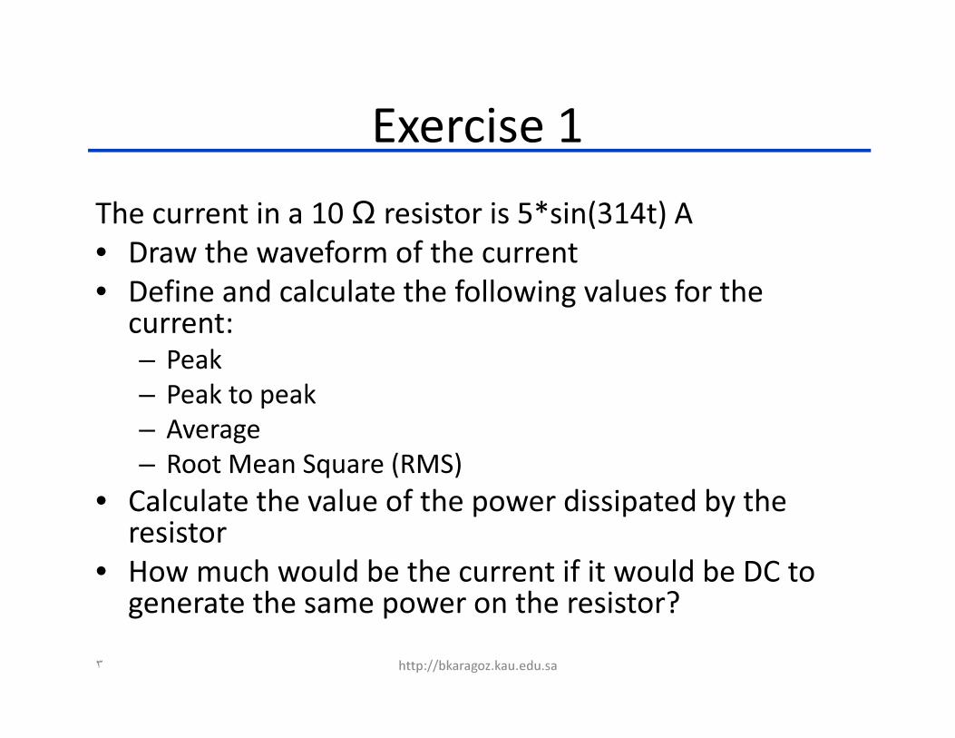
Exercise 1
The current in a 10 Ω resistor is 5*sin(314t) A
• Draw the waveform of the current
• Define and calculate the following values for the current:
– Peak
– Peak to peak
– Average
– Root Mean Square (RMS)
• Calculate the value of the power dissipated by the resistor
• How much would be the current if it would be DC to generate the same power on the resistor?
٣ http://bkaragoz.kau.edu.sa
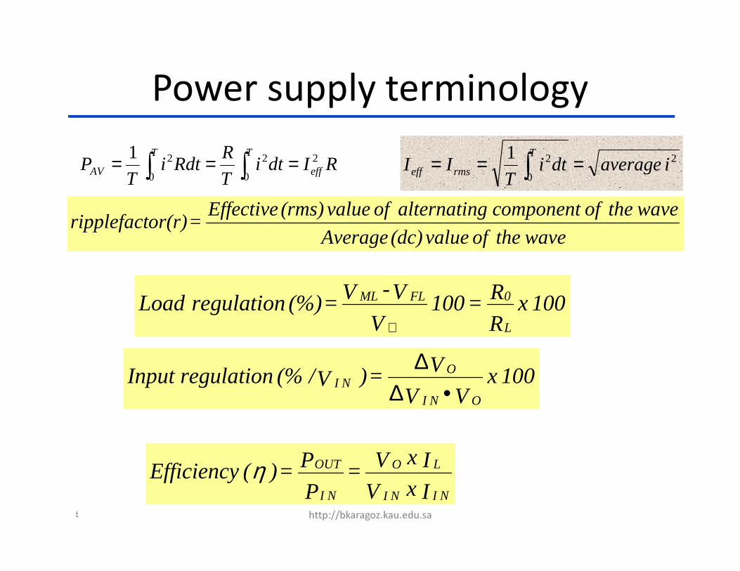
Power supply terminology
wavethe of value (dc) Average
wavethe of component galternatin of value (rms) Effective = or(r)ripplefact
100 xR
R = 100 V
V - V = (%) regulation LoadL
0FLML
⊗
100 xVV
V = ) V/ (% regulation InputONI
ONI •∆
∆
I x V
I x V = P
P = )( EfficiencyNINI
LO
NI
OUTη
2
0
21iaveragedti
TII
T
rmseff === ∫RIdtiT
RRdti
TP eff
TT
AV2
0
2
0
21 === ∫∫
٤ http://bkaragoz.kau.edu.sa

Current
Alternating
πt
π/2 π 2 π
Im
-Im
OutputStep-downtransformer
Rectifier Filter RegulatorDC
ACInput
AC linecomponents
Block diagram of a linear regulated power supply
CurrentDirect
π/2 π 2π
Im
-Im
Idc
πt
٥ http://bkaragoz.kau.edu.sa

127 Vrms
60 Hz
+
Fuse
Unregulateddc output
Transientsuppressor
ac line filter
Snubber
ac line transformer
Bridge rectifier
Filter capacitor
Input
socket
Unregulated supply with ac line components
(a transient suppressor and line filter)
٦ http://bkaragoz.kau.edu.sa

127 Vrms
60 Hz
+
Fuse
Unregulateddc output
Transientsuppressor
ac line filter
Snubber
ac line transformer
Bridge rectifier
Filter capacitor
Input
socket
•fast blow fuses cut the power
as quick as they can
•slow blow fuses tolerate
more short term overload
•wire link fuses are just an
open piece of wire, and have
poorer overload
characteristics than glass and
ceramic fuses
٧ http://bkaragoz.kau.edu.sa

127 Vrms
60 Hz
+
Fuse
Unregulateddc output
Transientsuppressor
ac line filter
Snubber
ac line transformer
Bridge rectifier
Filter capacitor
Input
socket
Transient suppressor and line filter
٨ http://bkaragoz.kau.edu.sa

127 Vrms
60 Hz
+
Fuse
Unregulateddc output
Transientsuppressor
ac line filter
Snubber
ac line transformer
Bridge rectifier
Filter capacitor
Input
socket
RC Snubbers
٩ http://bkaragoz.kau.edu.sa
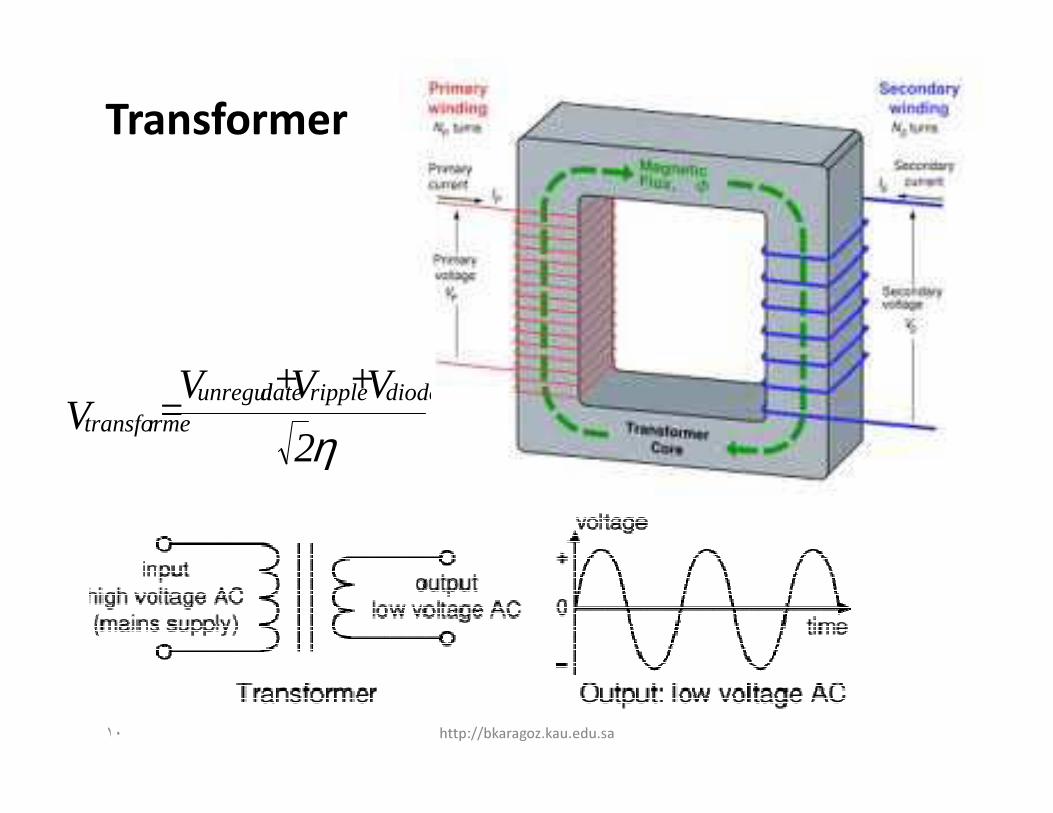
Transformer
η 2V + V + V
= Vdiodesrippledunregulate
rtransforme
١٠ http://bkaragoz.kau.edu.sa

Exercise – 2
• For transformer in a power supply
– Required average output voltage = 10 V
– Ripple voltage = 1 V
– Diode drops = 2 V
– Output current (average) = 1 A
– Efficiency (η) of the transformer = 0.8
• Find the required output voltage of the transformer
• Find the input current of the transformer if the input voltage is 220 V
• Find the output power delivered by the power supply
• Find the power loss by the transformer
η 2
V + V + V = V
diodesrippledunregulatertransforme
١١ http://bkaragoz.kau.edu.sa

Rectifier Diodes
Diode Maximum Current Maximum
Reverse Voltage
1N4001 1A 50V
1N4002 1A 100V
1N4007 1A 1000V
1N5401 3A 100V
1N5408 3A 1000V
١٢ http://bkaragoz.kau.edu.sa

Half-Wave Rectified (Single Diode
Rectifier)
Output: half-wave varying DC (Pulsating DC)
(using only half the AC wave)
127 Vrms
60 Hz
VmSinωt
D1
RL
+
-
Vo = Vm - Vd with Vd ≅ 1 volt.
Vdc = (Vm - Vd)/π , Vrms = (Vm - Vd)/2
yielding a ripple factor (r) = 1.21
١٣ http://bkaragoz.kau.edu.sa
ππππ/2 ππππ 2ππππ
Vm
-Vm
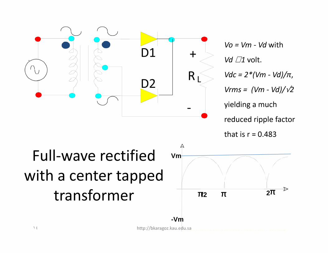
Full-wave rectified
with a center tapped
transformer
D1
R LD2
+
-
Vo = Vm - Vd with
Vd ≅ 1 volt.
Vdc = 2*(Vm - Vd)/π,
Vrms = (Vm - Vd)/√2
yielding a much
reduced ripple factor
that is r = 0.483
١٤ http://bkaragoz.kau.edu.sa
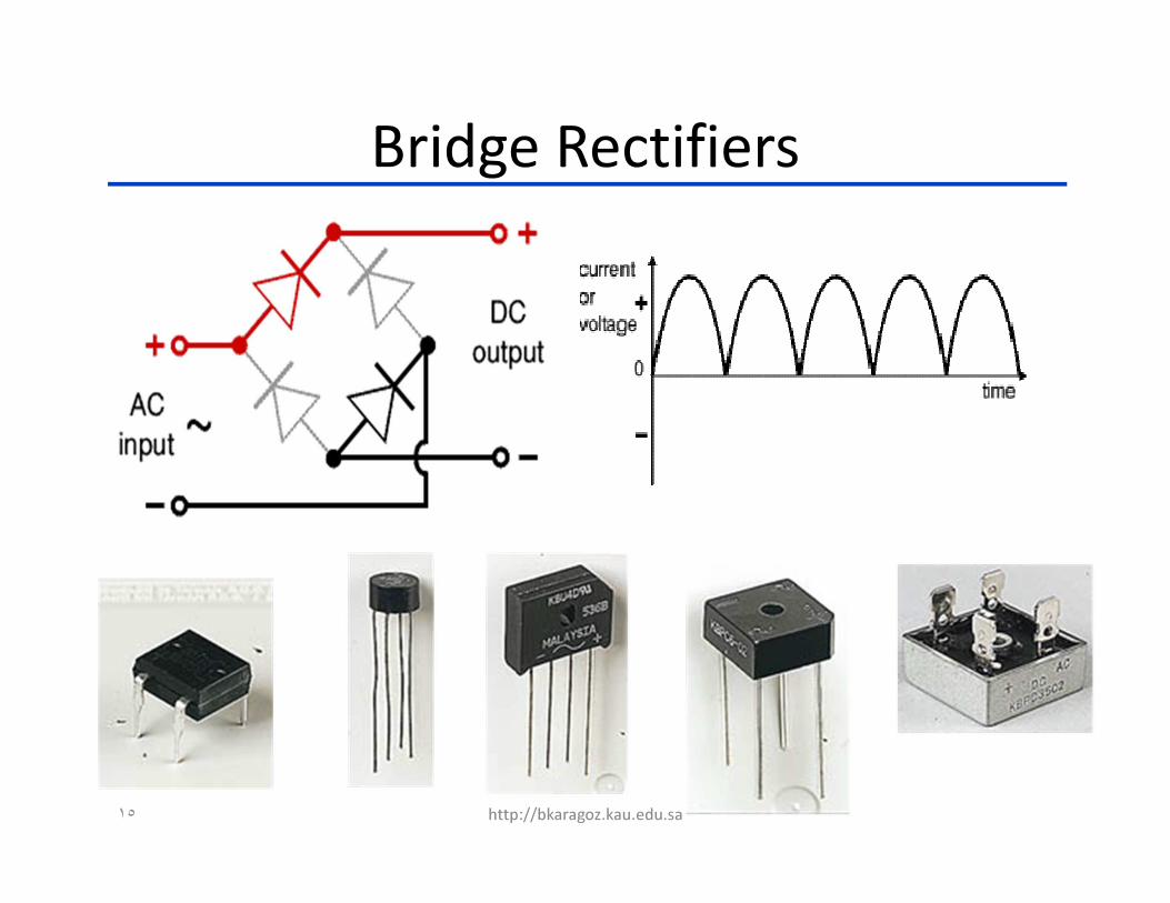
Bridge Rectifiers
١٥ http://bkaragoz.kau.edu.sa

D1
D4D2
D3π/2 π 2 π
Vm
-VmPulsating DC
Full-wave rectified
with a bridge
rectifier
D1
R L
D2
D3
D4
+
-
١٦ http://bkaragoz.kau.edu.sa

Smoothing Filters
Types of smoothing filters
• Capacitive
• Inductive
• L – Section
• π - Section
١٧ http://bkaragoz.kau.edu.sa
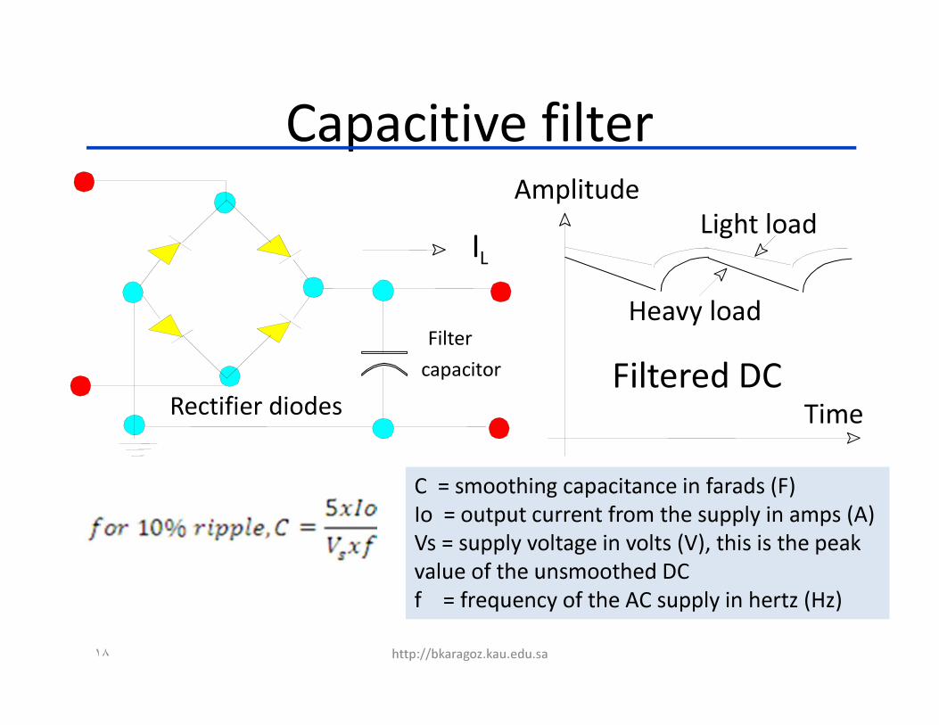
Rectifier diodes
Filter
capacitor
IL
Amplitude
Time
Heavy load
Light load
Filtered DC
Capacitive filter
C = smoothing capacitance in farads (F)
Io = output current from the supply in amps (A)
Vs = supply voltage in volts (V), this is the peak
value of the unsmoothed DC
f = frequency of the AC supply in hertz (Hz)
١٨ http://bkaragoz.kau.edu.sa
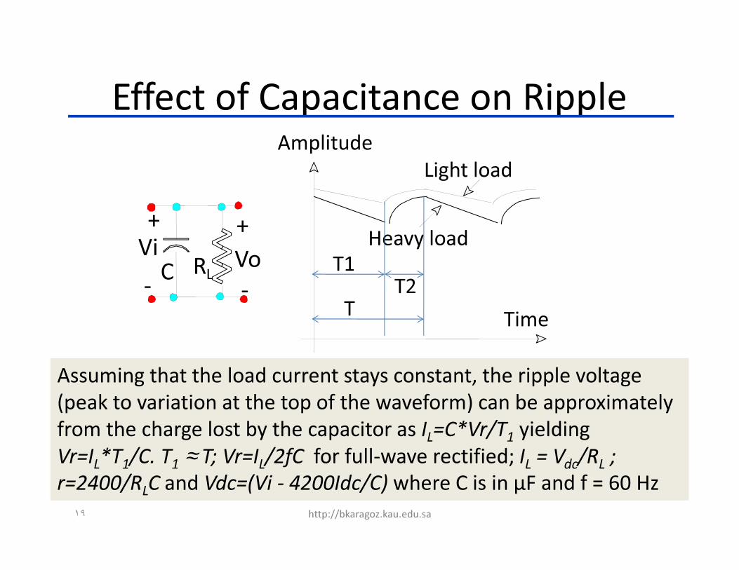
Effect of Capacitance on Ripple
+ +
- -RLC
ViVo
Amplitude
Time
Heavy load
Light load
T1
T2
T
Assuming that the load current stays constant, the ripple voltage
(peak to variation at the top of the waveform) can be approximately
from the charge lost by the capacitor as IL=C*Vr/T
1yielding
Vr=IL*T
1/C. T
1≈ T; Vr=I
L/2fC for full-wave rectified; I
L= V
dc/R
L;
r=2400/RLC and Vdc=(Vi - 4200Idc/C) where C is in μF and f = 60 Hz
١٩ http://bkaragoz.kau.edu.sa
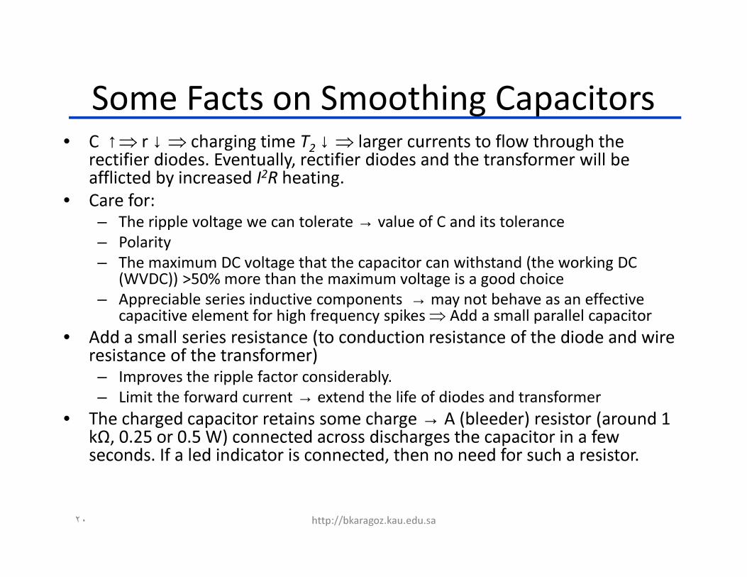
Some Facts on Smoothing Capacitors• C ↑⇒ r ↓⇒ charging time T
2↓⇒ larger currents to flow through the
rectifier diodes. Eventually, rectifier diodes and the transformer will be afflicted by increased I2R heating.
• Care for:
– The ripple voltage we can tolerate → value of C and its tolerance
– Polarity
– The maximum DC voltage that the capacitor can withstand (the working DC (WVDC)) >50% more than the maximum voltage is a good choice
– Appreciable series inductive components → may not behave as an effective capacitive element for high frequency spikes ⇒ Add a small parallel capacitor
• Add a small series resistance (to conduction resistance of the diode and wire resistance of the transformer)
– Improves the ripple factor considerably.
– Limit the forward current → extend the life of diodes and transformer
• The charged capacitor retains some charge → A (bleeder) resistor (around 1
kΩ, 0.25 or 0.5 W) connected across discharges the capacitor in a few seconds. If a led indicator is connected, then no need for such a resistor.
٢٠ http://bkaragoz.kau.edu.sa
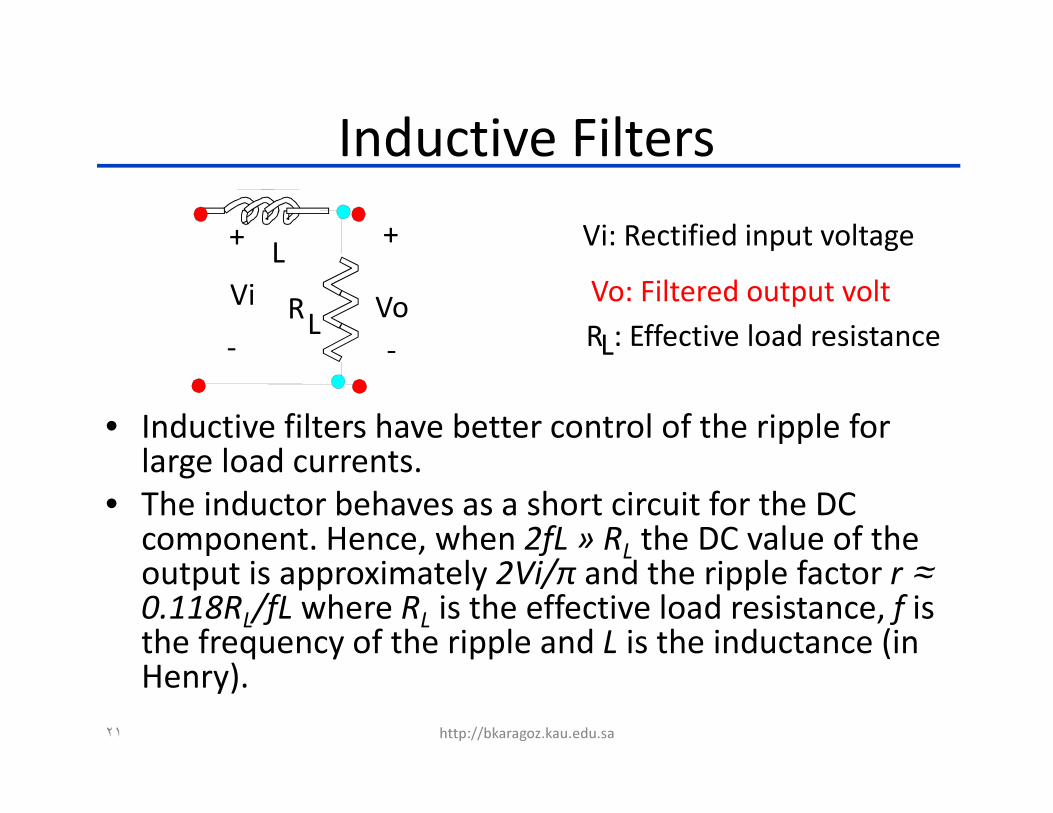
++
- -
L
RL
Vi Vo
Vi: Rectified input voltage
Vo: Filtered output volt
RL: Effective load resistance
Inductive Filters
• Inductive filters have better control of the ripple for large load currents.
• The inductor behaves as a short circuit for the DC component. Hence, when 2fL » R
Lthe DC value of the
output is approximately 2Vi/π and the ripple factor r ≈0.118R
L/fL where R
Lis the effective load resistance, f is
the frequency of the ripple and L is the inductance (in Henry).
٢١ http://bkaragoz.kau.edu.sa

+ +
- -
L
RLC1 C2
Vi
+ +
- -
L
RL
CVi Vo Vo
L - section π - section
L and ππππ section filters
r = 0.83/LC
Vdc = 0.636Vm
r = 3300/C1RLC2L
Vdc = Vm-4200*Idc/C
٢٢ http://bkaragoz.kau.edu.sa

VoVo
++
- -
L
RLVi
Inductive
+ +
- -RLC
ViVo
Capacitive
+ +
- -
L
RLCVi Vo
L - section
+ +
- -
L
RLC1 C2
Vi
π - section
RL
2400 0.83 3300
r ----- ------ ----- ---------1600L R
LC LC C
1R
LC2
L
Vdc 0.636Vm Vm-4200Idc/C 0.636Vm Vm-4200Idc/C
Vi: Rectified input voltage; Vo: Filtered output volt.
RL: Effective load resistance; Frequency: 60 Hz
Effective (rms) value of AC part
Ripple factor (r) = -----------------------------------------Average (dc) value of output
Summary of filter responses
٢٣ http://bkaragoz.kau.edu.sa
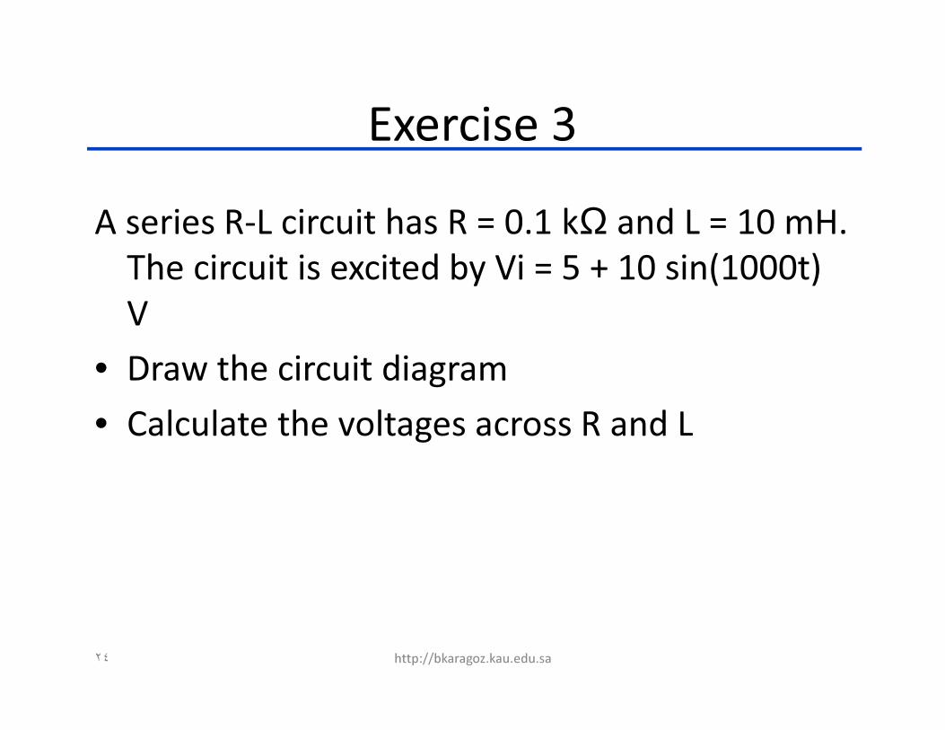
Exercise 3
A series R-L circuit has R = 0.1 kΩ and L = 10 mH.
The circuit is excited by Vi = 5 + 10 sin(1000t)
V
• Draw the circuit diagram
• Calculate the voltages across R and L
٢٤ http://bkaragoz.kau.edu.sa
Duties for next lecture
• Study linear (dissipative) regulated power
supplies from the lecture notes
• Solve the exercises in this lecture in detail at
home and bring it to the next lecture for a
discussion in class
• Be prepared for a quiz and active learning
http://bkaragoz.kau.edu.sa٢٥