902.2 mechanical properties - new millennium refers to open web, load-carrying members utilizing...
TRANSCRIPT

88 www.newmill.com/digital-toolsDiscover the easiest way to specify special profile joists:
This specification covers the design, manufacture and use of Special Profile Steel Joists, SP-Series. Load and Resistance Factor Design (LRFD) and Allowable Strength Design (ASD) are included in this specification.
The term “Special Profile Steel Joists, SP-Series” as used herein, refers to open web, load-carrying members utilizing hot-rolled or cold-formed steel, including cold-formed steel whose yield strength has been attained by cold working. SP-Series steel joists are suitable for the direct support of roof decks in buildings.
The design of SP-Series joists’ chord and web sections shall be based on a yield strength of at least 36 ksi (250 MPa), but not greater than 50 ksi (345 MPa). Steel used for SP-Series joist chord or web sections shall have a minimum yield strength determined in accordance with one of the procedures specified in Section 902.2, which is equal to the yield strength assumed in the design. SP-Series joists shall be designed in accordance with these specifications to support the loads specified in the joist designation.
The term “Yield Strength” as used herein shall designate the yield level of a material as determined by the applicable method outlined in paragraph 13.1 “Yield Point,” and in paragraph 13.2 “Yield Strength,” of ASTM A370, Standard Test Methods and Definitions for Mechanical Testing of Steel Products, or as specified in Section 902.2 of this specification.
902.1 STEEL
The steel used in the manufacture of chord and web sections shall conform to one of the following ASTM specifications:
• Carbon Structural Steel, ASTM A36/A36M
• High-Strength Low-Alloy Structural Steel, ASTM A242/A242M
• High-Strength Carbon-Manganese Steel of Structural Quality, ASTM A529/A529M, Grade 50
• High-Strength Low-Alloy Columbium-Vanadium Structural Steel, ASTM A572/A572M, Grade 42 and 50
• High-Strength Low-Alloy Structural Steel with 50 ksi (345 MPa) Minimum Yield Point to 4 inches (100 mm) thick, ASTM A588/A588M
• Steel, Sheet and Strip, High-Strength, Low-Alloy, Hot-Rolled and Cold-Rolled, with Improved Corrosion Resistance, ASTM A606
• Steel, Sheet, Cold-Rolled, Carbon, Structural, High Strength Low-Alloy and High-Strength Low-Alloy with Improved Formability, ASTM A1008/A1008M
• Steel, Sheet and Strip, Hot-Rolled, Carbon, Structural, High-Strength Low-Alloy and High-Strength Low-Alloy with Improved Formability, and Ultra-High Strength, ASTM A1011/A1011M
or shall be of suitable quality ordered or produced to other than the listed specifications, provided that such material in the state used for final assembly and manufacture is weldable and is proven by tests performed by the producer or manufacturer to have the properties specified in Section 902.2.
902.2 MECHANICAL PROPERTIES
The yield strength used as a basis for the design stresses prescribed in Section 903 shall be either 36 ksi (250 MPa) or 50 ksi (345 MPa). Evidence that the steel furnished meets or exceeds the design yield strength shall, if requested, be provided in the form of an affidavit or by witnessed or certified test reports.
For material used without consideration of increase in yield strength resulting from cold forming, the specimens shall be taken from as-rolled material. In the case of material, the mechanical properties of which conform to the requirements of one of the listed specifications, the test specimens and procedures shall conform to those of such specifications and to ASTM A370.
In the case of material, the mechanical properties of which do not conform to the requirements of one of the listed specifications, the test specimens and procedures shall conform to the applicable requirements of ASTM A370, and the specimens shall exhibit a yield strength equal to or exceeding the design yield strength and an elongation of not less than (a) 20 percent in 2 inches (51 mm) for sheet and strip, or (b) 18 percent in 8 inches (203 mm) for plates, shapes, and bars with adjustments for thickness for plates, shapes, and bars as prescribed in ASTM A36/A36M, A242/A242M, A529/A529M, A572/A572M, A588/A588M, whichever specification is applicable on the basis of design yield strength.
The number of tests shall be as prescribed in ASTM A6/A6M for plates, shapes, and bars; and ASTM A606, A1008/A1008M and A1011/A1011M for sheet and strip.
Stan
dard
Spe
cific
atio
nSP
-Ser
ies
Tabl
esSP
-Ser
ies
Des
ign
Spec
ial P
rofil
e Jo
ists
Intro
duct
ion

89www.newmill.com/digital-toolsDiscover the easiest way to specify special profile joists:
If as-formed strength is utilized, the test reports shall show the results of tests performed on full section specimens in accordance with the provisions of the AISI North American Specifications for the Design of Cold-Formed Steel Structural Members. They shall also indicate compliance with these provisions and with the following additional requirements:
a) The yield strength calculated from the test data shall equal or exceed the design yield strength.
b) Where tension tests are made for acceptance and control purposes, the tensile strength shall be at least 6 percent greater than the yield strength of the section.
c) Where compression tests are used for acceptance and control purposes, the specimen shall withstand a gross shortening of 2 percent of its original length without cracking. The length of the specimen shall be not greater than 20 times the least radius of gyration.
d) If any test specimen fails to pass the requirements of the subparagraphs (a), (b), or (c) above, as applicable, two retests shall be made of specimens from the same lot. Failure of one of the retest specimens to meet such requirements shall be the cause for rejection of the lot represented by the specimens.
902.3 WELDING ELECTRODES
The following electrodes shall be used for arc welding:
a) For connected members both having a specified minimum yield strength greater than 36 ksi (250 MPa): AWS A5.1: E70XX AWS A5.5: E70XX-X AWS A5.17: F7XX-EXXX, F7XX-ECXXX flux-electrode combination AWS A5.18: ER70S-X, E70C-XC, E70C-XM AWS A5.20: E7XT-X, E7XT-XM AWS A5.23: F7XX-EXXX-XX, F7XX-ECXXX-XX AWS A5.28: ER70S-XXX, E70C-XXX AWS A5.29: E7XTX-X, E7XTX-XM
b) For connected members both having a specified minimum yield strength of 36 ksi (250 MPa) or one having a specified minimum yield strength of 36 ksi (250 MPa), and the other having a specified minimum yield strength greater than 36 ksi (250 MPa):
AWS A5.1: E60XX AWS A5.17: F6XX-EXXX, F6XX-ECXXX flux-electrode combination AWS A5.20: E6XT-X, E6XT-XM AWS A5.29: E6XTX-X, E6XTX-XM or any of those listed in Section 902.3(a)
Other welding methods, providing equivalent strength as demonstrated by tests, may be used.
902.4 PAINT
The standard shop paint is intended to protect the steel for only a short period of exposure in ordinary atmospheric conditions and shall be considered an impermanent and provisional coating. When specified, the standard shop paint shall conform to one of the following:
a) Steel Structures Painting Council Specification, SSPC No. 15
b) Shall be a shop paint which meets the minimum performance requirements of the above listed specification
903.1 METHOD
SP-Series joists shall be designed in accordance with these specifications as simply supported, uniformly loaded trusses supporting a roof deck so constructed as to brace the top chord of the joists against lateral buckling. All joists are designed as pinned at one end and roller bearing on the opposite end to prevent horizontal thrust to the supporting structure. The end fixity conditions of Scissor and Arch joists require special consideration from the specifying professional regarding end anchorage conditions. (See Sections 904.1 and 904.7)
Where any applicable design feature is not specifically covered herein, the design shall be in accordance with the following specifications:
a) Where the steel used consists of hot-rolled shapes, bars or plates, use the American Institute of Steel Construction, Specification for Structural Steel Buildings.
b) For members that are cold-formed from sheet or strip steel, use the American Iron and Steel Institute, North American Specification for the Design of Cold-Formed Steel Structural Members.
Design Basis:
Designs shall be made according to the provisions in this Specification for either Load and Resistance Factor Design (LRFD) or for Allowable Strength Design (ASD).
Load Combinations:
LRFD:
When load combinations are not specified to NMBS, the required stress shall be computed for the factored loads based on the factors and load combinations as follows:
1.4D 1.2D + 1.6 (L, or Lr, or S, or R)
STANDARD SPECIFICATION, SP-SERIES
IntroductionSpecial Profile Joists
SP-Series Design
SP-Series TablesStandard Specification

90 www.newmill.com/digital-toolsDiscover the easiest way to specify special profile joists:
ASD:
When load combinations are not specified to NMBS, the required stress shall be computed based on the load combinations as follows:
D D + (L, or Lr, or S, or R)
Where:
D = dead load due to the weight of the structural elements and the permanent features of the structure L = live load due to occupancy and movable equipment Lr = roof live load S = snow load R = load due to initial rainwater or ice exclusive of the ponding contribution
The current ASCE 7, Minimum Design Loads for Buildings and Other Structures shall be used for LRFD and ASD load combinations. This provision pertains exclusively to the combination of loads and does not imply that NMBS generate or verify load development for SP-Series.
903.2 DESIGN AND ALLOWABLE STRESSES
Design Using Load and Resistance Factor Design (LRFD)
Joists shall have their components so proportioned that the required stresses, fu, shall not exceed ΦFn where,
fu = required stress ksi (MPa) Fn = nominal stress ksi (MPa) Φ = resistance factor ΦFn = design stress ksi (MPa)
Design Using Allowable Strength Design (ASD)
Joists shall have their components so proportioned that the required stresses, f, shall not exceed Fn /Ὼ where,
fu = required stress ksi (MPa) Fn = nominal stress ksi (MPa) Ὼ = safety factor Fn/Ὼ = allowable stress ksi (MPa)
Stresses:
(a) Tension: Φt = 0.90 (LRFD), Ὼt = 1.67 (ASD)
For chords: Fy = 50 ksi (345 MPa) For webs: Fy = 50 ksi (345 MPa) or Fy = 36 ksi (250 MPa)
Design Stress = 0.9Fy (LRFD) (903.2-1) Allowable Stress = 0.6Fy (ASD) (903.2-2)
(b) Compression: Φc = 0.90 (LRFD), Ὼc = 1.67 (ASD)
For members with
For members with
For hot-rolled sections, “Q” is the full reduction factor for slender compression elements.
Design Stress = 0.9Fcr (LRFD) (903.2-6) Allowable Stress = 0.6Fcr (ASD) (903.2-7)
In the above equations, ℓ is taken as the distance in inches (mm) between panel points for the chord members and the appropriate length for web members, and r is the corresponding least radius of gyration of the member or any component thereof. E is equal to 29,000 ksi (200,000 MPa).
Use 1.2 ℓ/rx for a crimped, first primary compression web member when a moment-resistant weld group is not used for this member; where rx = member radius of gyration in the plane of the joist.
For cold-formed sections the method of calculating the nominal column strength is given in the AISI North American Specification for the Design of Cold-Formed Steel Structural Members.
(c) Bending: Φb = 0.90 (LRFD), Ὼb = 1.67 (ASD)
Bending calculations are to be based on using the elastic section modulus.
For chords and web members other than solid rounds: Fy = 50 ksi (345 MPa)
Design Stress = 0.9Fy (LRFD) (903.2-8) Allowable Stress = 0.6Fy (ASD) (903.2-9)
For web members of solid round cross section: Fy = 50 ksi (345 MPa) or Fy = 36 ksi (250 MPa)
Design Stress = 1.45Fy (LRFD) (903.2-10) Allowable Stress = 0.95Fy (ASD) (903.2-11)
85
ASD:
When load combinations are not specified to NMBS, the required stress shall be computed based on the load combinations as follows:
D D + (L, or Lr, or S, or R)
Where:
D = dead load due to the weight of the structural elements and the permanent features of the structure
L = live load due to occupancy and movable equipment Lr = roof live load S = snow load R = load due to initial rainwater or ice exclusive of the
ponding contribution The current ASCE 7, Minimum Design Loads for Buildings and Other Structures shall be used for LRFD and ASD load combinations. This provision pertains exclusively to the combination of loads and does not imply that NMBS verify or generate load development for Special Profile Joists. 903.2 DESIGN AND ALLOWABLE STRESSES Design Using Load and Resistance Factor Design (LRFD) Joists shall have their components so proportioned that the required stresses, fu, shall not exceed Fn where,
fu = required stress ksi (MPa) Fn = nominal stress ksi (MPa) = resistance factor Fn = design stress ksi (MPa)
Design Using Allowable Strength Design (ASD)
Joists shall have their components so proportioned that the required stresses, f, shall not exceed Fn / where,
fu = required stress ksi (MPa) Fn = nominal stress ksi (MPa) = safety factor Fn/ = allowable stress ksi (MPa)
Stresses:
(a) Tension: t = 0.90 (LRFD), t = 1.67 (ASD)
For Chords: Fy = 50 ksi (345 MPa) For Webs: Fy = 50 ksi (345 MPa), or Fy = 36 ksi (250 MPa)
Design Stress = 0.9Fy (LRFD) (903.2-1) Allowable Stress = 0.6Fy (ASD) (903.2-2)
(b) Compression: c = 0.90 (LRFD), c = 1.67 (ASD)
For members with yQF
E71.4rK
yF
QF
cr F658.0QF e
y
(903.2-3)
For members with yQF
E4.71rK
ecr F877.0F (903.2-4)
Fe = Elastic buckling stress determined in accordance with Equation 903.2-5
22
e
rK
EF
(903.2-5)
For hot-rolled sections, “Q” is the full reduction factor for slender compression elements.
Design Stress = 0.9Fcr (LRFD) (903.2-6) Allowable Stress = 0.6Fcr (ASD) (903.2-7)
In the above equations, is taken as the distance in inches (mm) between panel points for the chord members and the appropriate length for web members, and r is the corresponding least radius of gyration of the member or any component thereof. E is equal to 29,000 ksi (200,000 MPa).
Use 1.2 xr for a crimped, first primary compression web member when a moment-resistant weld group is not used for this member; where xr = member radius of gyration in the plane of the joist.
For cold-formed sections the method of calculating the nominal column strength is given in the AISI North American Specification for the Design of Cold-Formed Steel Structural Members. (c) Bending: b = 0.90 (LRFD), b = 1.67 (ASD) Bending calculations are to be based on using the elastic section modulus.
For chords and web members other than solid rounds:
Fy = 50 ksi (345 MPa)
Design Stress = 0.9Fy (LRFD) (903.2-8) Allowable Stress = 0.6Fy (ASD) (903.2-9)
For web members of solid round cross section:
Fy = 50 ksi (345 MPa), or Fy = 36 ksi (250 MPa)
Design Stress = 1.45Fy (LRFD) (903.2-10)
(903.2-3)
(903.2-4)
(903.2-5)
STANDARD SPECIFICATION, SP-SERIES
Fcr = 0.877Fe
Fe = Elastic buckling stress determined in accordance with Equation 903.2-5
Stan
dard
Spe
cific
atio
nSP
-Ser
ies
Tabl
esSP
-Ser
ies
Des
ign
Spec
ial P
rofil
e Jo
ists
Intro
duct
ion

91www.newmill.com/digital-toolsDiscover the easiest way to specify special profile joists:
For bearing plates: Fy = 50 ksi (345 MPa) or Fy = 36 ksi (250 MPa)
Design Stress = 1.35Fy (LRFD) (903.2-12) Allowable Stress = 0.90Fy (ASD) (903.2-13)
(d) Weld Strength:
Shear at throat of fillet welds:
Nominal Shear Stress = Fnw = 0.6Fexx (903.2-14)
LRFD: Φw = 0.75
Design Shear Strength = ΦRn = ΦwFnw A = 0.45Fexx A (903.2-15)
ASD: Ὼw = 2.0
Allowable Shear Strength = Rn/Ὼw = FnwA/Ὼw = 0.3Fexx A (903.2-16)
Where A = effective throat area
Made with E70 series electrodes or F7XX-EXXX flux-electrode combinations.
Fexx = 70 ksi (483 MPa)
Made with E60 series electrodes or F6XX-EXXX flux-electrode combinations.
Fexx = 60 ksi (414 MPa)
Tension or compression on groove or butt welds shall be the same as those specified for the connected material.
Divergence Stress: The design of chords formed into arcs through cold rolling shall include a divergence stress in the design. A secondary moment in the chord resulting from the divergence of the actual member from the node-to-node linear design element shall be accounted for in the design.
For chords rolled to a radius, the secondary moment stress shall be equal to:
Pr = axial force required in the member
c = distance from neutral axis to the extreme fiber results in two stress values for asymmetric sections such as double angles
Ix = moment of inertia about axis perpendicular to radius of divergence
R = radius of divergence from neutral axis. Usually the radius of cold rolling for Bowstring or Arch Joists
d = straight-line distance from node to node
903.3 MAXIMUM SLENDERNESS RATIOS
The slenderness ratios, 1.0 ℓ/r and 1.0 ℓs/r of members as a whole or any component part shall not exceed the values given in Table 903.3-1, Parts A.
The effective slenderness ratio, Kℓ/r to be used in calculating the nominal stresses Fcr and Fe, is the largest value as determined from Table 903.3-1, Parts B and C. See P.N. Chod and T.V. Galambos, Compression Chords Without Fillers in Longspan Steel Joists, Research Report No. 36, June 1975 Structural Division, Civil Engineering Department, Washington University, St. Louis, Mo.
In compression members when fillers or ties are used, they shall be spaced so that the ℓs/rz ratio of each component does not exceed the governing ℓ/r ratio of the member as a whole.
The terms used in Table 903.3-1 are defined as follows:
ℓ = length center-to-center of panel points, except ℓ = 36 inches (914 mm) for calculating ℓ/ry of top chord member. ℓs = maximum length center-to-center between panel point and filler (tie), or between adjacent fillers (ties). rx = member radius of gyration in the plane of the joist. ry = member radius of gyration out of the plane of the joist. rz = least radius of gyration of a member component.
86
Allowable Stress = 0.95Fy (ASD) (903.2-11)
For bearing plates:
Fy = 50 ksi (345 MPa), or Fy = 36 ksi (250 MPa)
Design Stress = 1.35Fy (LRFD) (903.2-12) Allowable Stress = 0.90Fy (ASD) (903.2-13)
(d) Weld Strength:
Shear at throat of fillet welds:
Nominal Shear Stress = Fnw = 0.6Fexx (903.2-14)
LRFD: w = 0.75
Design Shear Strength = Rn = wFnw A = 0.45Fexx A (903.2-15)
ASD: w = 2.0
Allowable Shear Strength = Rn/w = FnwA/w = 0.3Fexx A (903.2-16) Where A = effective throat area
Made with E70 series electrodes or F7XX-EXXX flux-electrode combinations. Fexx = 70 ksi (483 MPa)
Made with E60 series electrodes or F6XX-EXXX flux-electrode combinations. Fexx = 60 ksi (414 MPa)
Tension or compression on groove or butt welds shall be the same as those specified for the connected material.
Divergence Stress: The design of chords formed into arches through cold rolling shall include a divergence stress in the design. A secondary moment in the chord resulting from the divergence of the actual member from the node-to-node linear design element shall be accounted for in the design. In some cases the divergence stress may counter act the bending stress of the chord, in this case the effects of divergence stress is ignored.
For chords rolled to a radius the secondary moment stress shall be equal to:
4
22 dRR
IcP
x
rdivergence
(903.2-17)
Pr = axial force required in the member c = distance from neutral axis to the extreme fiber
results in two stresses for asymmetric sections such as double angles
Ix = moment of inertia about axis perpendicular to radius
of divergence R = radius of divergence from neutral axis. Usually the
radius of cold rolling for Bowstring or Arch Joists d = straight-line distance from node to node
903.3 MAXIMUM SLENDERNESS RATIOS The slenderness ratios, 1.0 /r and 1.0 s/r of members as a whole or any component part shall not exceed the values given in Table 903.3-1, Parts A. The effective slenderness ratio, K/r* to be used in calculating the nominal stresses Fcr and Fe, is the largest value as determined from Table 903.3-1, Parts B and C. In compression members when fillers or ties are used, they shall be spaced so that the s/rz ratio of each component does not exceed the governing /r ratio of the member as a whole. The terms used in Table 903.3-1 are defined as follows:
= length center-to-center of panel points, except = 36 in. (914 mm) for calculating /ry of top chord member.
s = maximum length center-to-center between panel point and filler (tie), or between adjacent fillers (ties).
rx = member radius of gyration in the plane of the joist. ry = member radius of gyration out of the plane of the joist. rz = least radius of gyration of a member component.
* See P.N. Chod and T. V. Galambos, Compression Chords Without Fillers in Longspan Steel Joists, Research Report No. 36, June 1975 Structural Division, Civil Engineering Department, Washington University, St. Louis, Mo.
(903.2-17)
STANDARD SPECIFICATION, SP-SERIES
IntroductionSpecial Profile Joists
SP-Series Design
SP-Series TablesStandard Specification

92 www.newmill.com/digital-toolsDiscover the easiest way to specify special profile joists:
TABLE 903.3-1
kℓ/rx kℓ/ry kℓ/rz kℓs/rz
I TOP CHORD INTERIOR PANEL
A. The slenderness ratios, 1.0ℓ/r and 1.0ℓs/r , of members as a whole or any component part shall not exceed 90.
B. The effective slenderness ratio, kℓ/r, to determine Fcr where k is: 1. With fillers or ties 0.75 1.0 --- 1.0 2. Without fillers or ties --- --- 0.75 --- 3. Single component members 0.75 1.0 --- ---
C. The effective slenderness ratio, kℓ/r, to determine Fe where k is: 1. With fillers or ties 0.75 --- --- --- 2. Without fillers or ties 0.75 --- --- --- 3. Single component members 0.75 --- --- ---
II TOP CHORD END PANEL
A. The slenderness ratios, 1.0ℓ/r and 1.0ℓs/r , of members as a whole or any component part shall not exceed 120.
B. The effective slenderness ratio, kℓ/r, to determine Fcr where k is: 1. With fillers or ties 1.0 1.0 --- 1.0 2. Without fillers or ties --- --- 1.0 --- 3. Single component members 1.0 1.0 --- ---
C. The effective sl enderness ratio, kℓ/r, to determine Fe where k is: 1. With fillers or ties 1.0 --- --- --- 2. Without fillers or ties 1.0 --- --- --- 3. Single component members 1.0 --- --- ---
III TENSION MEMBERS – CHORDS AND WEBS
A. The slenderness ratios, 1.0ℓ/r and 1.0ℓs/r , of members as a whole or any component part shall not exceed 240.
IV COMPRESSION MEMBERS
A. The slenderness ratios, 1.0 and 1.0ℓs/r , of members as a whole or any component part shall not exceed 200.
B. The effective slenderness ratio, kℓ/r, to determine Fcr where k is: 1. With fillers or ties 0.75 1.0 --- 1.0 2. Without fillers or ties --- --- 1.0 --- 3. Single component members 0.75* 1.0 --- ---
* If moment-resistant weld groups are not used at the ends of a crimped, first primary compression web member, then 1.2ℓ/rx must be used.
MAXIMUM AND EFFECTIVE SLENDERNESS RATIOS
STANDARD SPECIFICATION, SP-SERIES
Stan
dard
Spe
cific
atio
nSP
-Ser
ies
Tabl
esSP
-Ser
ies
Des
ign
Spec
ial P
rofil
e Jo
ists
Intro
duct
ion
93www.newmill.com/digital-toolsDiscover the easiest way to specify special profile joists:
903.4 MEMBERS
(a) Chords
The bottom chord shall be designed as an axially loaded tension member.
Bottom chords that are rolled for arched chord joist shall be designed to include divergence stress per Equation 903.2-17, in combination with tension forces.
For LRFD:
For ASD:
The radius of gyration of the top chord about its vertical axis shall not be less than ℓ/120 where ℓ is the spacing in inches (mm) between lines of bridging as specified in Section 904.5(d).
The top chord shall be considered as stayed laterally by the roof deck provided the requirements of Section 904.9(c) of this specification are met.
The top chord shall be designed as a continuous member subject to combined axial and bending stresses and shall be so proportioned that:
For LRFD:
at the panel point:
at the mid panel:
fau = Pu/A, required compressive stress, ksi (MPa) Pu = required axial strength using LRFD load combinations, kips (N) fbu = Mu/S, required bending stress at the location under consideration, ksi (MPa)
σdiv = divergence stress applied where applicable as defined in Equation 903.2-17 Mu = required flexural strength using LRFD load combinations, kip-in (N-mm) S = elastic section modulus, in3 (mm3) Fcr = nominal axial compressive stress based on ℓ/r as defined in Section 903.2(b), ksi (MPa) Cm = 1 - 0.3 fau/ΦFe for end panels Cm = 1 - 0.4 fau/ΦFe for interior panels Fy = specified minimum yield strength, ksi (MPa)
Fe =
Where ℓ is the panel length, in inches (mm), as defined in Section 903.2(b), and rx is the radius of gyration about the axis bending.
Q = form factor defined in Section 903.2(b) A = area of the top chord, in.2 (mm2)
For ASD:
at the panel point: at the mid panel:
fa = P/A, required compressive stress, ksi (MPa) P = required axial strength using ASD load combinations, kips (N) fb = M/S, required bending stress at the location under consideration, ksi (MPa) σdiv = divergence stress applied where applicable as defined in Equation 903.2-17 M = required flexural strength using ASD load combinations, kip-in (N-mm) S = elastic Section Modulus, in3 (mm3) Fa = allowable axial compressive stress based on ℓ/r as defined in Section 903.2(b), ksi (MPa)
88
903.4 MEMBERS (a) Chords
The bottom chord shall be designed as an axially loaded tension member. Bottom chords that are rolled for arched chord joist shall be designed to include divergence stress per Section 903.2.17, in combination with tension forces.
For LRFD: ydivau Ff 9.0 (903.4-1)
For ASD: ydiva Ff 6.0 (903.4-2)
The radius of gyration of the top chord about its vertical axis shall not be less than /120 where is the spacing in inches (mm) between lines of bridging as specified in Section 904.5(d).
The top chord shall be considered as stayed laterally by the roof deck provided the requirements of Section 904.9(c) of this specification are met.
The top chord shall be designed as a continuous member subject to combined axial and bending stresses and shall be so proportioned that:
For LRFD:
at the panel point: ybuau F9.0ff (903.4-3)
at the mid panel:
for, 2.0Ff
crc
au
,
0.11
98
ybec
au
divbum
crc
au
FQFffC
Ff
(903.4-4)
for, 2.0Ff
crc
au
,
0.11
2
ybec
au
divbum
crc
au
FQFffC
Ff
(903.4-5)
fau = Pu/A, Required compressive stress, ksi (MPa) Pu = required axial strength using LRFD load
combinations, kips (N) fbu = Mu/S, Required bending stress at the location under
consideration, ksi (MPa)
σdiv = Divergence stress applied where applicable as defined in Section 903.2.17
Mu = required flexural strength using LRFD load combinations, kip-in (N-mm)
S = elastic section modulus, in3 (mm3) Fcr = nominal axial compressive stress based on /r as
defined in Section 903.2(b), ksi (MPa) Cm = 1 - 0.3 fau/F’e for end panels Cm = 1 - 0.4 fau/F’e for interior panels Fy = specified minimum yield strength, ksi (MPa)
Fe = 2
2
)/( xrkE
, ksi (MPa)
Where is the panel length, in inches (mm), as defined in Section 903.2(b) and rx is the radius of gyration about the axis of bending.
Q = form factor defined in Section 903.2(b) A = area of the top chord, in.2 (mm2)
For ASD:
at the panel point: yba F6.0ff (903.4-6)
at the mid panel:
for 2.0Ff
a
a ,
0.167.11
98
be
a
divbm
a
a
QFFf
fCFf
(903.4-7)
for 2.0Ff
a
a ,
0.167.11
2
be
a
divbm
a
a
QFFf
fCFf
(903.4-8)
fa = P/A, Required compressive stress, ksi (MPa) P = required axial strength using ASD load
combinations, kips (N) fb = M/S, Required bending stress at the location under
consideration, ksi (MPa) σdiv = Divergence stress applied where applicable as
defined in Section 903.2.17 M = required flexural strength using ASD load
combinations, kip-in (N-mm) S = elastic Section Modulus, in3 (mm3) Fa = allowable axial compressive stress based on /r as
defined in Section 903.2(b), ksi (MPa)
STANDARD SPECIFICATION, SP-SERIES
(903.4-3)
(903.4-4)
(903.4-5)
(903.4-1)
(903.4-2)
(903.4-6)
(903.4-7)
(903.4-8)
88
903.4 MEMBERS (a) Chords
The bottom chord shall be designed as an axially loaded tension member. Bottom chords that are rolled for arched chord joist shall be designed to include divergence stress per Section 903.2.17, in combination with tension forces.
For LRFD: ydivau Ff 9.0 (903.4-1)
For ASD: ydiva Ff 6.0 (903.4-2)
The radius of gyration of the top chord about its vertical axis shall not be less than /120 where is the spacing in inches (mm) between lines of bridging as specified in Section 904.5(d).
The top chord shall be considered as stayed laterally by the roof deck provided the requirements of Section 904.9(c) of this specification are met.
The top chord shall be designed as a continuous member subject to combined axial and bending stresses and shall be so proportioned that:
For LRFD:
at the panel point: ybuau F9.0ff (903.4-3)
at the mid panel:
for, 2.0Ff
crc
au
,
0.11
98
ybec
au
divbum
crc
au
FQFffC
Ff
(903.4-4)
for, 2.0Ff
crc
au
,
0.11
2
ybec
au
divbum
crc
au
FQFffC
Ff
(903.4-5)
fau = Pu/A, Required compressive stress, ksi (MPa) Pu = required axial strength using LRFD load
combinations, kips (N) fbu = Mu/S, Required bending stress at the location under
consideration, ksi (MPa)
σdiv = Divergence stress applied where applicable as defined in Section 903.2.17
Mu = required flexural strength using LRFD load combinations, kip-in (N-mm)
S = elastic section modulus, in3 (mm3) Fcr = nominal axial compressive stress based on /r as
defined in Section 903.2(b), ksi (MPa) Cm = 1 - 0.3 fau/F’e for end panels Cm = 1 - 0.4 fau/F’e for interior panels Fy = specified minimum yield strength, ksi (MPa)
Fe = 2
2
)/( xrkE
, ksi (MPa)
Where is the panel length, in inches (mm), as defined in Section 903.2(b) and rx is the radius of gyration about the axis of bending.
Q = form factor defined in Section 903.2(b) A = area of the top chord, in.2 (mm2)
For ASD:
at the panel point: yba F6.0ff (903.4-6)
at the mid panel:
for 2.0Ff
a
a ,
0.167.11
98
be
a
divbm
a
a
QFFf
fCFf
(903.4-7)
for 2.0Ff
a
a ,
0.167.11
2
be
a
divbm
a
a
QFFf
fCFf
(903.4-8)
fa = P/A, Required compressive stress, ksi (MPa) P = required axial strength using ASD load
combinations, kips (N) fb = M/S, Required bending stress at the location under
consideration, ksi (MPa) σdiv = Divergence stress applied where applicable as
defined in Section 903.2.17 M = required flexural strength using ASD load
combinations, kip-in (N-mm) S = elastic Section Modulus, in3 (mm3) Fa = allowable axial compressive stress based on /r as
defined in Section 903.2(b), ksi (MPa)
STANDARD SPECIFICATION – SP SERIES
89
903.4 MEMBERS (a) Chords
The bottom chord shall be designed as an axially loaded tension member. Bottom chords that are rolled for arched chord joist shall be designed to include divergence stress per Equation 903.2-17, in combination with tension forces.
For LRFD: ydivau Ff 9.0 (903.4-1)
For ASD: ydiva Ff 6.0 (903.4-2)
The radius of gyration of the top chord about its vertical axis shall not be less than /120 where is the spacing in inches (mm) between lines of bridging as specified in Section 904.5(d).
The top chord shall be considered as stayed laterally by the roof deck provided the requirements of Section 904.9(c) of this specification are met.
The top chord shall be designed as a continuous member subject to combined axial and bending stresses and shall be so proportioned that:
For LRFD:
at the panel point: ybuau F9.0ff (903.4-3)
at the mid panel:
for 2.0Ff
crc
au
,
0.1
19
8
yFbQeFc
auf
divbufmC
crFc
auf
(903.4-4)
for 2.0Ff
crc
au
,
0.1
12
yFbQeFc
auf
divbufmC
crFc
auf
(903.4-5)
fau = Pu/A, required compressive stress, ksi (MPa) Pu = required axial strength using LRFD load
combinations, kips (N) fbu = Mu/S, required bending stress at the location under
consideration, ksi (MPa)
σdiv = divergence stress applied where applicable as defined in Equation 903.2-17
Mu = required flexural strength using LRFD load combinations, kip-in (N-mm)
S = elastic section modulus, in3 (mm3) Fcr = nominal axial compressive stress based on /r as
defined in Section 903.2(b), ksi (MPa) Cm = 1 - 0.3 fau/Fe for end panels Cm = 1 - 0.4 fau/Fe for interior panels Fy = specified minimum yield strength, ksi (MPa)
Fe = 2
2
)/( xrkE
, ksi (MPa)
Where is the panel length, in inches (mm), as defined in Section 903.2(b), and rx is the radius of gyration about the axis of bending.
Q = form factor defined in Section 903.2(b) A = area of the top chord, in.2 (mm2)
For ASD:
at the panel point: yba F6.0ff (903.4-6)
at the mid panel:
for 2.0Ff
a
a ,
0.1
67.11
9
8
bQFeFaf
divbfmC
aFaf
(903.4-7)
for 2.0Ff
a
a ,
0.167.1
12
bQFeFaf
divbfmC
aFaf
(903.4-8)
fa = P/A, required compressive stress, ksi (MPa) P = required axial strength using ASD load
combinations, kips (N) fb = M/S, required bending stress at the location under
consideration, ksi (MPa) σdiv = divergence stress applied where applicable as
defined in Equation 903.2-17 M = required flexural strength using ASD load
combinations, kip-in (N-mm) S = elastic Section Modulus, in3 (mm3) Fa = allowable axial compressive stress based on /r as
defined in Section 903.2(b), ksi (MPa)
IntroductionSpecial Profile Joists
SP-Series Design
SP-Series TablesStandard Specification

94 www.newmill.com/digital-toolsDiscover the easiest way to specify special profile joists:
Fb = 0.6 Fy, allowable bending stress, ksi (MPa) Cm = 1 - 0.5 fa/Fe for end panels Cm = 1 - 0.67 fa/Fe for interior panels
(b) Web
The vertical shears to be used in the design of the web members shall be determined from full uniform loading, but such vertical shears shall be not less than 25 percent of the end reaction.
Interior vertical web members used in modified Warren-type web systems shall be designed to resist the gravity loads supported by the member plus an additional axial load of 1/2 of 1 percent of the top chord axial force.
(c) Eccentricity
Members connected at a joint shall have their center-of-gravity lines meet at a point, if practical. Eccentricity on either side of the neutral axis of chord members may be neglected when it does not exceed the distance between the neutral axis and the back of the chord. Otherwise, provision shall be made for the stresses due to eccentricity. Ends of joists shall be proportioned to resist bending produced by eccentricity at the support.
(d) Extended Ends
Extended top chords or full depth cantilever ends require the special attention and coordination between the specifying professional and NMBS. The magnitude and location of the loads to be supported, deflection requirements, and proper bracing shall be clearly indicated in the contract documents and joist erection plans.
903.5 CONNECTIONS
(a) Methods
Joist connections and splices shall be made by attaching the members to one another by arc or resistance welding or other accredited methods.
(1) Welded Connectionsa) Selected welds shall be inspected visually by the manufacturer.
Prior to this inspection, weld slag shall be removed.b) Cracks are not acceptable and shall be repaired.c) Thorough fusion shall exist between weld and base metal
for the required design length of the weld; such fusion shall be verified by visual inspection.
d) Unfilled weld craters shall not be included in the design length of the weld.
e) Undercut shall not exceed 1/16 inch (2 mm) for welds oriented parallel to the principal stress.
f) The sum of surface (piping) porosity diameters shall not exceed 1/16 inch (2 mm) in any 1 inch (25 mm) of design weld length.
g) Weld spatter that does not interfere with paint coverage is acceptable.
Welding Program
NMBS shall have a program for establishing weld procedures and operator qualification, and for weld sampling and testing. (Refer to Steel Joist Institute Technical Digest #8, Welding of Open Web Steel Joists.)
Weld Inspection by Outside Agencies (See Section 904.13 of this specification).
The agency shall arrange for visual inspection to determine that welds meet the acceptance standards of Section 903.5(a)(1). Ultrasonic, X-ray, and magnetic particle testing are inappropriate for joists due to the configurations of the components and welds.
(b) Strength
Joint Connections shall develop the maximum force due to any of the design loads, but not less than 50 percent of the strength of the member in tension or compression, whichever force is the controlling factor in the selection of the member.
Shop Splices may occur at any point in chord or web members. Splices shall be designed for the member force but not less than 50 percent of the member strength. Members containing a butt weld splice shall develop an ultimate tensile force of at least 2 x 0.6 Fy times the full design area of the chord or web. The term “member” shall be defined as all component parts comprising the chord or web, at the point of splice.
(c) Field Splices
Field Splices shall be designed by NMBS in accordance with the AISC Steel Construction Manual. Splices shall be designed for the member forces, but not less than 50 percent of the member strength.
Top chord splices may be designed as “compression only” when the joist is not subject to an in-service net uplift. Most all joists are subject to negative bending moment during hoisting at erection and “compression only” splices shall be designed for these tension forces.
903.6 CAMBER
SP-Series joists are furnished with no camber. NMBS can provide special camber as required by the contract documents. The specifying professional shall give consideration to coordinating joist elevation with adjacent framing. Technical performance requirements shall be coordinated between NMBS and the specifying professional.
903.7 VERIFICATION OF DESIGN & MANUFACTURE
(a) Design Calculations
Design calculations prepared by a professional engineer registered in the state of the NMBS manufacturing plant are available for NMBS SP-Series joists upon request.
STANDARD SPECIFICATION, SP-SERIES
(2)
(3)
(1)
(2)
Stan
dard
Spe
cific
atio
nSP
-Ser
ies
Tabl
esSP
-Ser
ies
Des
ign
Spec
ial P
rofil
e Jo
ists
Intro
duct
ion

95www.newmill.com/digital-toolsDiscover the easiest way to specify special profile joists:
904.1 USAGE
This specification shall apply to any type of structure where roof decks are to be supported directly by SP-Series joists installed as hereinafter specified. Where SP-Series joists are used other than on simple spans under uniformly distributed loading as prescribed in Section 903.1, they shall be investigated and modified if necessary to limit the required stresses to those listed in Section 903.2.
CAUTION: If a rigid connection of the bottom chord is to be made to the column or other support, it shall be made only after the application of the dead loads. The joist is then no longer simply supported, and the system must be investigated for continuous frame action by the specifying professional.
The designed detail of a rigid-type connection and moment plates shall be shown in the contract documents and on the structural drawings by the specifying professional. The moment plates shall be furnished by other than NMBS.
904.2 SPAN
The term “span” as used herein is defined as shown on the diagram at the right. On beams, the span is to the center line of the supporting steel and on a wall, span is defined as 6” (152 mm) over the support. In each case, the vertical location of the point for determining span is at the top of the joist top chord.
When the bearing points of a SP-Series joist are at different elevations, the span of the joist shall be determined by the length along the slope.
In all cases, the design length of the joist is equal to the span less 4” (102 mm).
904.3 DEPTH
The nominal depth as specified in the designation of SP-Series joists shall be the maximum depth of the joist as measured between the top and bottom chords. When joist geometry consists of parallel chords, (e.g. Scissor or Arch), the measurement shall be made perpendicular to the top and bottom chord. If a profile not conforming to one of the four types or variations in this catalog is used, the nominal depth shall be measured perpendicular to a chord tangent, at a discontinuous panel point, (i.e. top or bottom chord ridge), or at the greatest nominal depth along the span. In any case, dimensions to be used in design shall be as specified in the contract documents.
SP-Series joists may have various chord configurations and may have bearing conditions that cause the excessive pitch in the chords. The design of the joist in all cases shall be comprehensive to meet all SP-Series design requirements set forth in the contract documents.
STANDARD SPECIFICATION, SP-SERIES
91
904.1 USAGE This specification shall apply to any type of structure where roof decks are to be supported directly by SP-Series joists installed as hereinafter specified. Where SP-Series joists are used other than on simple spans under uniformly distributed loading as prescribed in Section 903.1, they shall be investigated and modified if necessary to limit the required stresses to those listed in Section 903.2. CAUTION: If a rigid connection of the bottom chord is to be made to the column or other support, it shall be made only after the application of the dead loads. The joist is then no longer simply supported, and the system must be investigated for continuous frame action by the specifying professional. The designed detail of a rigid-type connection and moment plates shall be shown on the structural drawings by the specifying professional. The moment plates shall be furnished by other than NMBS. 904.2 SPAN The term “span” as used herein is defined as shown on the diagram at the right. On beams, the span is to the center line of the supporting steel and on a wall, span is defined as 6” (152 mm) over the support. In each case, the vertical location of the point for determining span is at the top of the joist top chord. When the bearing points of a SP-Series joist are at different elevations, the span of the joist shall be determined by the length along the slope. In all cases, the design length of the joist is equal to the span less 4” (102 mm). 904.3 DEPTH The nominal depth as specified in the designation of SP-Series joists shall be the maximum depth of the joist as measured between the top and bottom chords. When joist geometry consists of parallel chords, (e.g. Scissor or Arch), the measurement shall be made perpendicular to the top and bottom chord. If a profile not prescribing to one of the four types or variations in this catalog is used, the nominal depth shall be measured perpendicular to a chord tangent, at a discontinuous panel point, (i.e. top or bottom chord ridge), or at the greatest nominal depth along the span. In any case, dimensions to be used in design shall be as specified in the contract documents. SP-Series joists may have various chord configurations and may have bearing conditions that cause the excessive pitch in the chords. The design of the joist in all cases shall be comprehensive to meet all design requirements set forth in the contract documents.
IntroductionSpecial Profile Joists
SP-Series Design
SP-Series TablesStandard Specification

96 www.newmill.com/digital-toolsDiscover the easiest way to specify special profile joists:
904.4 END SUPPORTS
(a) Masonry and Concrete
SP-Series joists supported by masonry or concrete are to bear on steel bearing plates and shall be designed as steel bearing. Due consideration of the end reactions and all other vertical or lateral forces shall be taken by the specifying professional in the design of the steel bearing plate and the masonry or concrete. The ends of SP-Series joists shall extend a distance of not less than 6 inches (152 mm) over the masonry or concrete support and be anchored to the steel bearing plate. The plate shall be located not more than 1/2 inch (13 mm) from the face of the wall and shall not be less than 9 inches (229 mm) wide perpendicular to the length of the joist. The plate is to be designed by the specifying professional and shall be furnished by other than NMBS.
Where it is deemed necessary to bear less than 6 inches (152 mm) over the masonry or concrete support, special consideration is to be given to the design of the steel bearing plate and the masonry or concrete by the specifying professional. The joists must bear a minimum of 4 inches (102 mm) on the steel bearing plate.
(b) Steel
Due consideration of the end reactions and all other vertical and lateral forces shall be taken by the specifying professional in the design of the steel support. The ends of SP-Series joists shall extend a distance of not less than 4 inches (102 mm) over the steel supports for top chords less than angle size L5” x 5” x ½”, otherwise 6 inches (153mm).
904.5 BRIDGING
Top and bottom chord bridging is required and shall consist of one or both of the following types.
(a) Horizontal
Horizontal bridging shall consist of continuous horizontal steel members with a ℓ/r ratio of the bridging member of not more than 300, where ℓ is the distance in inches (mm) between attachments and r is the least radius of gyration of the bridging member.
(b) Diagonal
Diagonal bridging shall consist of cross-bracing with a ℓ/r ratio of not more than 200, where ℓ is the distance in inches (mm) between connections and r is the least radius of gyration of the bridging member. Where cross-bracing members are connected at their point of intersection, the ℓ distance shall be taken as the distance in inches (mm) between connections at the point of intersection of the bridging members and the connections to the chord of the joists.
(c) Bridging Types
For spans less than or equal to 20 feet (6.096 m), welded horizontal bridging may be used. If the joist center of gravity is above the supports, the row of bridging nearest the center is required to be bolted diagonal bridging.
For spans more than 20 feet (6.096 m) all rows shall be bolted diagonal bridging. Where the joist spacing is less than 2/3 times the joist depth at the bridging row, both bolted diagonal bridging and bolted horizontal bridging shall be used.
(d) Quantity and Spacing
The maximum spacing of lines of bridging shall not exceed the values in Table 904.5-1.
(e) Connections
Connections to the chords of the steel joists shall be made by positive mechanical means or by welding, and capable of resisting a horizontal force not less than that specified in Table 904.5-1.
(f) Bottom Chord Bearing Joists
Where bottom chord bearing joists are utilized, a row of diagonal bridging shall be provided near the support(s). This bridging shall be installed and anchored before hoisting cables are released.
TOP CHORD LEG SIZE
< 2” 11’-0” 400 lbs.
2” 12’-0” 550 lbs.
2½” 13’-0” 750 lbs.
3” 16’-0” 950 lbs.
3½” 16’-0” 1300 lbs.
4” 21’-0” 1850 lbs.
5” 21’-0” 2300 lbs.
6” x 6” x 0.500” 26’-0” 2800 lbs.
6” x 6” x 0.625” 30’-0” 3450 lbs.
6” x 6” x 0.75” 30’-0” 4050 lbs.
TABLE 904.5-1
BRIDGING SPACING AND FORCES
Nominal bracing force is unfactored. 8” chords – contact NMBS
STANDARD SPECIFICATION, SP-SERIES
MAXIMUMBRIDGINGSPACING
NOMINAL FORCE
REQUIRED
Stan
dard
Spe
cific
atio
nSP
-Ser
ies
Tabl
esSP
-Ser
ies
Des
ign
Spec
ial P
rofil
e Jo
ists
Intro
duct
ion
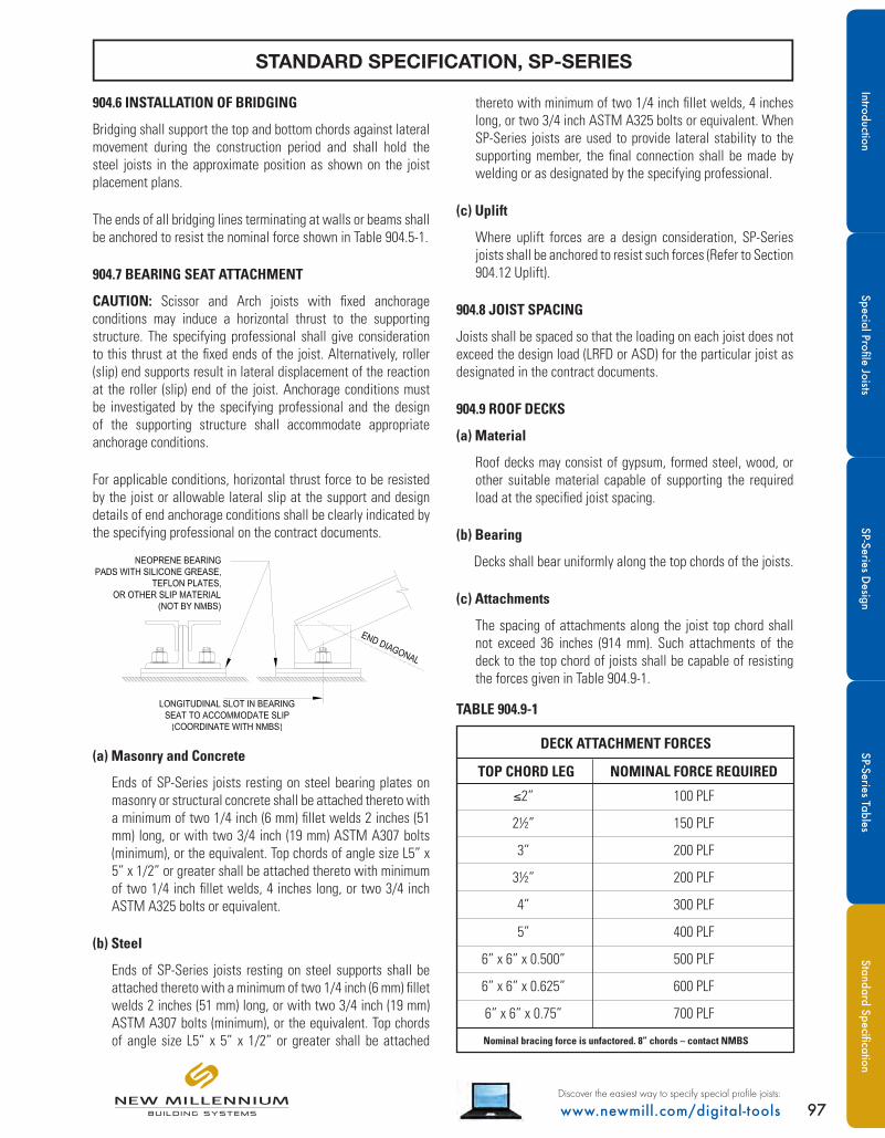
97www.newmill.com/digital-toolsDiscover the easiest way to specify special profile joists:
904.6 INSTALLATION OF BRIDGING
Bridging shall support the top and bottom chords against lateral movement during the construction period and shall hold the steel joists in the approximate position as shown on the joist placement plans.
The ends of all bridging lines terminating at walls or beams shall be anchored to resist the nominal force shown in Table 904.5-1.
904.7 BEARING SEAT ATTACHMENT
CAUTION: Scissor and Arch joists with fixed anchorage conditions may induce a horizontal thrust to the supporting structure. The specifying professional shall give consideration to this thrust at the fixed ends of the joist. Alternatively, roller (slip) end supports result in lateral displacement of the reaction at the roller (slip) end of the joist. Anchorage conditions must be investigated by the specifying professional and the design of the supporting structure shall accommodate appropriate anchorage conditions.
For applicable conditions, horizontal thrust force to be resisted by the joist or allowable lateral slip at the support and design details of end anchorage conditions shall be clearly indicated by the specifying professional on the contract documents.
(a) Masonry and Concrete
Ends of SP-Series joists resting on steel bearing plates on masonry or structural concrete shall be attached thereto with a minimum of two 1/4 inch (6 mm) fillet welds 2 inches (51 mm) long, or with two 3/4 inch (19 mm) ASTM A307 bolts (minimum), or the equivalent. Top chords of angle size L5” x 5” x 1/2” or greater shall be attached thereto with minimum of two 1/4 inch fillet welds, 4 inches long, or two 3/4 inch ASTM A325 bolts or equivalent.
(b) Steel
Ends of SP-Series joists resting on steel supports shall be attached thereto with a minimum of two 1/4 inch (6 mm) fillet welds 2 inches (51 mm) long, or with two 3/4 inch (19 mm) ASTM A307 bolts (minimum), or the equivalent. Top chords of angle size L5” x 5” x 1/2” or greater shall be attached
thereto with minimum of two 1/4 inch fillet welds, 4 inches long, or two 3/4 inch ASTM A325 bolts or equivalent. When SP-Series joists are used to provide lateral stability to the supporting member, the final connection shall be made by welding or as designated by the specifying professional.
(c) Uplift
Where uplift forces are a design consideration, SP-Series joists shall be anchored to resist such forces (Refer to Section 904.12 Uplift).
904.8 JOIST SPACING
Joists shall be spaced so that the loading on each joist does not exceed the design load (LRFD or ASD) for the particular joist as designated in the contract documents.
904.9 ROOF DECKS
(a) Material
Roof decks may consist of gypsum, formed steel, wood, or other suitable material capable of supporting the required load at the specified joist spacing.
(b) Bearing
Decks shall bear uniformly along the top chords of the joists.
(c) Attachments
The spacing of attachments along the joist top chord shall not exceed 36 inches (914 mm). Such attachments of the deck to the top chord of joists shall be capable of resisting the forces given in Table 904.9-1.
TABLE 904.9-1
DECK ATTACHMENT FORCES
Nominal bracing force is unfactored. 8” chords – contact NMBS
TOP CHORD LEG NOMINAL FORCE REQUIRED
≤2” 100 PLF
2½” 150 PLF
3” 200 PLF
3½” 200 PLF
4” 300 PLF
5” 400 PLF
6” x 6” x 0.500” 500 PLF
6” x 6” x 0.625” 600 PLF
6” x 6” x 0.75” 700 PLF
STANDARD SPECIFICATION, SP-SERIES
93
904.6 INSTALLATION OF BRIDGING Bridging shall support the top and bottom chords against lateral movement during the construction period and shall hold the steel joists in the approximate position as shown on the joist placement plans. The ends of all bridging lines terminating at walls or beams shall be anchored to resist the nominal force shown in Table 904.5-1. 904.7 BEARING SEAT ATTACHMENT CAUTION: Scissor and Arch joists with welded anchorage conditions may induce a horizontal thrust to the supporting structure. The specifying professional shall give consideration to this thrust at the fixed ends of the joist. Alternatively, roller (slip) end supports result in lateral displacement of the reaction at roller (slip) end of the joist. Anchorage conditions must be investigated by the specifying professional and the design of the supporting structure shall accommodate appropriate anchorage conditions. For applicable conditions, horizontal thrust force to be resisted by the joist or allowable lateral slip at the support and design details of end anchorage conditions shall be clearly indicated by the specifying professional in the contract documents.
(a) Masonry and Concrete
Ends of SP-Series joists resting on steel bearing plates on masonry or structural concrete shall be attached thereto with a minimum of two 1/4 inch (6 mm) fillet welds 2 inches (51 mm) long, or with two 3/4 inch (19 mm) ASTM A307 bolts (minimum), or the equivalent.
(b) Steel
Ends of SP-Series joists resting on steel supports shall be attached thereto with a minimum of two 1/4 inch (6 mm) fillet welds 2 inches (51 mm) long, or with two 3/4 inch (19 mm) ASTM A307 bolts (minimum), or the equivalent. When SP-Series joists are used to provide lateral stability to the supporting member, the final connection shall be made by welding or as designated by the specifying professional.
Uplift
Where uplift forces are a design consideration, SP-Series joists shall be anchored to resist such forces (Refer to Section 904.12 Uplift).
904.8 JOIST SPACING Joists shall be spaced so that the loading on each joist does not exceed the design load (LRFD or ASD) for the particular joist as designated in the contract documents. 904.9 ROOF DECKS (a) Material
Roof decks may consist of gypsum, formed steel, wood, or other suitable material capable of supporting the required load at the specified joist spacing.
(b) Bearing
Decks shall bear uniformly along the top chords of the joists.
(c) Attachments
The spacing of attachments along the joist top chord shall not exceed 36 inches (914 mm). Such attachments of the deck to the top chord of joists shall be capable of resisting the forces given in Table 904.9-1.
TABLE 904.9-1
DECK ATTACHMENT FORCES
TOP CHORD LEG NOMINAL FORCE REQUIRED
≤2” 100 PLF
2½” 150 PLF
3” 200 PLF
3½” 250 PLF
4” 400 PLF
5” 500 PLF
6” x 6” x 0.500” 600 PLF
6” x 6” x 0.625” 750 PLF
6” x 6” x 0.75” 850 PLF
Nominal bracing force is unfactored. 8” chords – contact NMBS
(d) Wood Nailers
Where wood nailers are used, such nailers in conjunction with deck shall be firmly attached to the top chords of the joists in conformance with Section 904.9(c).
IntroductionSpecial Profile Joists
SP-Series Design
SP-Series TablesStandard Specification

98 www.newmill.com/digital-toolsDiscover the easiest way to specify special profile joists:
(d) Wood Nailers
Where wood nailers are used, such nailers in conjunction with deck shall be firmly attached to the top chords of the joists in conformance with Section 904.9(c).
904.10 DEFLECTION
The deflection due to the design live or snow load shall not exceed the following:
Roofs:
• 1/360 of span where a plaster ceiling is attached or suspended
• 1/240 of span for all other cases
The specifying professional shall give consideration to the effects of deflection.
904.11 PONDING
The ponding investigation shall be performed by the specifying professional. Refer to Steel Joist Institute Technical Digest #3, Structural Design of Steel Joist Roofs to Resist Ponding Loads and AISC Steel Construction Manual.
904.12 UPLIFT
Where uplift forces due to wind are a design requirement, these forces must be indicated in the contract documents in terms of NET uplift in pounds per square foot (Pascals). The contract documents shall indicate if the net uplift is based upon LRFD or ASD. When these forces are specified, they must be considered in the design of joists and/or bridging. A single line of bottom chord bridging must be provided near the first bottom chord panel points whenever uplift due to wind forces is a design consideration.Refer to Steel Joist Institute Technical Digest #6, Structural Design of Steel Joist Roofs to Resist Uplift Loads.
904.13 INSPECTION
Joists shall be inspected by NMBS before shipment to verify compliance of materials and workmanship with the requirements of these specifications. If the buyer wishes an inspection of the steel joists by someone other than NMBS, they may reserve the right to do so in their “Invitation to Bid” or the accompanying “Job Specifications.”
Arrangements shall be made with NMBS for such inspection of the joists at the manufacturing facility by the buyer’s inspectors at buyer’s expense.
905.1 STABILITY
When it is necessary for the erector to climb on the SP-Series joists, extreme caution must be exercised since unbridged joists may exhibit some degree of instability under the erector’s weight. The degree of instability increases for geometries common with SP-Series joists due to their higher center-of-gravity.
(a) Stability Requirements
(1) Before an employee is allowed on the SP-Series joists: BOTH ends of joists at columns (or joists designated as column joists) shall be attached to its supports. For all other joists a minimum of one end shall be attached before the employee is allowed on the joist. The attachment shall be in accordance with Section 904.7.
When a bolted seat connection is used for erection purposes, as a minimum, the bolts must be snug tightened. The snug tight condition is defined as the tightness that exists when all plies of a joint are in firm contact. This may be attained by a few impacts of an impact wrench or the full effort of an employee using an ordinary spud wrench.
(2) For SP-Series joists with spans less than or equal to 20 feet (6.096 mm) that are permitted to have horizontal bridging per the restrictions of Section 904.5.(c), only one employee shall be allowed on the joists unless all bridging is installed and anchored.
(3) For SP-Series joists with spans more than 20 feet (6.096m), the following shall apply:
All rows of bridging shall be bolted diagonal bridging. Where the joist spacing is less than 2/3 times the joist depth at the bridging row, both bolted diagonal bridging and bolted horizontal bridging shall be used.
Hoisting cables shall not be released until all bolted bridging is installed and anchored, unless an alternate method of stabilizing the joist has been provided.
No more than one employee shall be allowed on these spans until all bridging is installed and anchored.
(4) When permanent bridging terminus points cannot be used during erection, additional temporary bridging terminus points are required to provide lateral stability.
STANDARD SPECIFICATION, SP-SERIES
a)
b)
c)
Stan
dard
Spe
cific
atio
nSP
-Ser
ies
Tabl
esSP
-Ser
ies
Des
ign
Spec
ial P
rofil
e Jo
ists
Intro
duct
ion

99www.newmill.com/digital-toolsDiscover the easiest way to specify special profile joists:
(5) In the case of bottom chord bearing joists, the ends of the joist must be restrained laterally per Section 904.5(f) before releasing the hoisting cables.
(6) After the joist is straightened and plumbed, and all bridging is completely installed and anchored, the ends of the joists shall be fully connected to the supports in accordance with Section 904.7.
(b) Landing and Placing Loads
(1) Except as stated in paragraph 905(b)(3) of this section, no “construction loads”(1) are allowed on the SP-Series joists until all bridging is installed and anchored, and all joist bearing seats are attached.
(2) During the construction period, loads placed on the SP-Series joists shall be distributed so as not to exceed the capacity of the joists.
(3) The weight of a bundle of joist bridging shall not exceed a total of 1000 pounds (454 kilograms). The bundle of joist bridging shall be placed on a minimum of three steel joists that are secured at one end. The edge of the bridging bundle shall be positioned within 1 foot (0.30 m) of the secured end.
(4) No bundle of deck may be placed on SP-Series joists until all bridging has been installed and anchored and all joist bearing ends attached, unless the following conditions are met:
a) The contractor has first determined from a “qualified person”(2) and documented in a site specific erection plan that the structure or portion of the structure is capable of supporting the load.
b) The bundle of decking is placed on a minimum of three steel joists.
c) The joists supporting the bundle of decking are attached at both ends.
d) All rows of bridging are installed and anchored.
e) The total weight of the decking does not exceed 4000 pounds (1816 kilograms).
f) The edge of the bundle of decking shall be placed within one foot (0.30 m) of the bearing surface of the joist end.
(5) The edge of the construction load shall be placed within one foot (0.30 m) of the bearing surface of the joist end.
(1) A copy of the OSHA Steel Erection Standard §1926.757, Open Web Steel Joists, is included at www.newmill.com for reference. Construction loads are defined therein for joist purposes as “any load other than the weight of the employee(s), the joists and the bridging.”
(2) A copy of the OSHA Steel Erection Standard §1926.757, Open Web Steel Joists, may be found at www.newmill.com for reference. Qualified person is defined therein as “one who, by possession of a recognized degree, certificate, or professional standing, or who by extensive knowledge, training, and experience, has successfully demonstrated the ability to solve or resolve problems relating to the subject matter, the work, or the project.”
(c) Field Welding
(1) All field welding shall be performed in accordance with the contract documents. Field welding shall not damage the joists.
(2) On cold-formed members whose yield strength has been attained by cold working, and whose as-formed strength is used in the design, the total length of weld at any one point shall not exceed 50 percent of the overall developed width of the cold-formed section.
(d) Handling
Particular attention should be paid to the erection of SP-Series joists. Care shall be exercised at all times to avoid damage to the joists and accessories.
Each joist shall be adequately braced laterally before any loads are applied. If lateral support is provided by bridging, the bridging lines, as defined in Section 905.1(a)(2) and 905.1(a)(3), must be anchored to prevent lateral movement.
(e) Fall Arrest Systems
SP-Series joists shall not be used as anchorage points for a fall arrest system unless written direction to do so is obtained from a “qualified person.”(2)
94
(b) Landing and Placing Loads
(1) Except as stated in paragraph 905(b)(3) of this section, no "construction loads”(1) are allowed on the SP-Series joists until all bridging is installed and anchored, and all joist bearing seats are attached.
(2) During the construction period, loads placed on the
SP-Series joists shall be distributed so as not to exceed the capacity of the joists.
(3) The weight of a bundle of joist bridging shall not
exceed a total of 1000 pounds (454 kilograms). The bundle of joist bridging shall be placed on a minimum of 3 steel joists that are secured at one end. The edge of the bridging bundle shall be positioned within 1 foot (0.30 m) of the secured end.
(4) No bundle of deck may be placed on SP-Series
joists until all bridging has been installed and anchored and all joist bearing ends attached, unless the following conditions are met:
a) The contractor has first determined from a “qualified person”(2) and documented in a site-specific erection plan that the structure or portion of the structure is capable of supporting the load.
b) The bundle of decking is placed on a minimum of 3 steel joists.
c) The joists supporting the bundle of decking are attached at both ends.
d) All rows of bridging are installed and anchored.
e) The total weight of the decking does not exceed 4000 pounds (1816 kilograms).
f) The edge of the bundle of decking shall be placed within one foot (0.30 m) of the bearing surface of the joist end.
g) The edge of the construction load shall be placed within one foot (0.30 m) of the bearing surface of the joist end.
(1) A copy of the OSHA Steel Erection Standard §1926.757, Open Web Steel Joists, is included at www.newmil.com for reference. Construction loads are defined therein for joist purposes as “any load other than the weight of the employee(s), the joists and the bridging.” (2) A copy of the OSHA Steel Erection Standard §1926.757, Open Web Steel Joists, may be found at www.newmil.com for reference. Qualified person is defined therein as “one who, by possession of a recognized degree, certificate, or professional standing, or who by extensive knowledge, training, and experience, has successfully demonstrated the ability to solve or resolve problems relating to the subject matter, the work, or the project.”
(c) Field Welding
(1) All field welding shall be performed in accordance with the contract documents. Field welding shall not damage the joists.
(2) On cold-formed members whose yield strength has
been attained by cold working, and whose as-formed strength is used in the design, the total length of weld at any one point shall not exceed 50 percent of the overall developed width of the cold-formed section.
(d) Handling
Particular attention should be paid to the erection of SP-Series joists. Care shall be exercised at all times to avoid damage to the joists and accessories.
Each joist shall be adequately braced laterally before any loads are applied. If lateral support is provided by bridging, the bridging lines, as defined in Section 905(a), paragraphs 2 and 3, must be anchored to prevent lateral movement.
(e) Fall Arrest Systems
SP-Series joists shall not be used as anchorage points for a fall arrest system unless written direction to do so is obtained from a “qualified person.”(2)
STANDARD SPECIFICATION, SP-SERIES
IntroductionSpecial Profile Joists
SP-Series Design
SP-Series TablesStandard Specification

100 www.newmill.com/digital-toolsDiscover the easiest way to specify special profile joists:
From the above diagram, the following information is used to enter the Gable Joists (SPGB) Tables on page 24.
Span: 40’-0” Center Depth: 46” End Depth: 6” Top Chord Pitch: 2” / foot
Total Load: 300 plf Total Load is the result of worst-case equivalent uniform load, WeqM-TL, based on investigation of all load cases.
Live Load: 120 plf
Uplift Load: 160 plf Net Uplift is not shown in the above diagram but is called out in the contract documents in the NET UPLIFT plan.
Joist Designation: 46 SPGB 300 / 120 / 160
From the information above, the correct geometry is found on page 28.
From the table: Joist Self-Weight: 8 PLF Bridging Required: 3 Rows of Bolted X-Bridging Seat Depth: 5” Deep Seats
Bridging and seat depth information should be noted in the contract documents and reflected in the section details.
95
The following examples serve as brief examples of going from a special profile geometry to the SP-Series load tables and determining the uniform self weight of the joist, the bridging requirements, the seat depth, and for Scissor (SPSC) and Arch (SPAC) Joists, the table will note if the horizontal deflection is greater than 2”. This allowance is for a pin-roller anchorage condition and the horizontal deflection, or slip, is at the roller end.
Gable Joist Example
From the above diagram, the following information is used to enter the Gable Joists (SPGB) Weight Tables on page 19. Span: 40’-0” Center Depth: 46” End Depth: 6” Top Chord Pitch: 2” / foot Total Load: 300 plf The weight tables are based on a 0.75 Live to Total Load ratio (300 x 0.75 = 225 plf) and check
for a Live Load Deflection not to exceed L/240, or 40’ x 12 / 240 = 2” maximum deflection for 225 plf.
Uplift Load: 160 plf This load is not shown in the above diagram but is called out on the contract drawings in the NET
UPLIFT plan and calculated for the given joist spacing. Joist Designation: 46 SPGB 300 / 225 / 160 From the information above, the correct geometry is found on page 23. From the table: Joist Self-Weight: 23 PLF Bridging Required: 3 Rows of Bolted X-Bridging Seat Depth: 5” Deep Seats Bridging and seat depth information should be noted on the contract documents and reflected in the section details.
906.1 GABLE EXAMPLE
GABLE JOIST (SPGB)
ALL TABLES ARE BASED ON ASD
SP-Series tables are based on a 0.75 Live to Total Load ratio (300 x 0.75 = 225 plf) and check for a Live Load deflection not to exceed L/240, or 40’ x 12 / 240 = 2” maximum deflection for 225 plf. The Live Load in this example, 120 plf, is less than 75 percent of the total load, 225 plf, therefore deflection is within limits.
STANDARD SPECIFICATION, SP-SERIES
The following abbreviated design examples demonstrate the selection of an SP-Series joist from the Weight Tables given all necessary geometry and loading information. The information found in the SP-Series Weight Tables includes the uniform self-weight of the joist as well as bridging and seat-depth requirements. For Scissor (SPSC) and Arch (SPAC) Joists, the table will note if the horizontal deflection is greater than 2”. This allowance is for a pin-roller bearing anchorage condition. The horizontal deflection, or slip, is at the roller end.
Stan
dard
Spe
cific
atio
nSP
-Ser
ies
Tabl
esSP
-Ser
ies
Des
ign
Spec
ial P
rofil
e Jo
ists
Intro
duct
ion

101www.newmill.com/digital-toolsDiscover the easiest way to specify special profile joists:
From the above diagram, the following information is used to enter the Bowstring Joists (SPBW) Tables on page 40.
Span: 40’-0” Center Depth: 46” End Depth: 6” Top Chord Radius: 62’-0”
Total Load: 800 plf Total Load is the result of worst-case equivalent uniform load, WeqM-TL, based on investigation of all load cases.
Live Load: 400 plf SP-Series tables are based on a 0.75 Live to Total Load ratio (800 x 0.75 = 600 plf) and check for a Live Load deflection not to exceed L/240, or 40’ x 12 / 240 = 2” maximum deflection for 600 plf. The Live Load in this example, 400 plf, is less than 75 percent of the total load, 600 plf, therefore deflection is within limits.
Uplift Load: 220 plf Net Uplift is not shown in the above diagram but is called out in the contract documents in the NET UPLIFT plan.
Joist Designation: 46 SPBW 800 / 400 / 220
From the information above, the correct geometry is found on page 44.
From the table: Joist Self-Weight: 17 PLF Bridging Required: 3 Rows of Bolted X-Bridging Seat Depth: 5” Deep Seats
Bridging and seat depth information should be noted in the contract documents and reflected in the section details.
906.2 BOWSTRING EXAMPLESTANDARD SPECIFICATION – SP SERIES
97
906.2 BOWSTRING EXAMPLE
EXAMPLES BASED ON ASD
From the above diagram, the following information is used to enter the Bowstring Joists (SPBW) Weight Tables on page 35. Span: 40’-0” Center Depth: 46” End Depth: 6” Top Chord Radius: 62’-0” Total Load: 800 plf Total Load is the result of worst-case equivalent uniform load, WeqM-TL, based on investigation of
all load cases. Live Load: 400 plf SP-Series tables are based on a 0.75 Live to Total Load ratio (800 x 0.75 = 600 plf) and check for
a Live Load Deflection not to exceed L/240, or 40’ x 12 / 240 = 2” maximum deflection for 600 plf. The Live Load in this example, 400 plf, is less than 75 percent of the total load, 600 plf, therefore deflection is within limits.
Uplift Load: 220 plf Net Uplift is not shown in the above diagram but is called out in the contract documents in the
NET UPLIFT plan. Joist Designation: 46 SPBW 800 / 400 / 220 From the information above, the correct geometry is found on page 39. From the table: Joist Self-Weight: 17 PLF Bridging Required: 3 Rows of Bolted X-Bridging Seat Depth: 5” Deep Seats Bridging and seat depth information should be noted in the contract documents and reflected in the section details.
BOWSTRING JOIST (SPBW)
ALL TABLES ARE BASED ON ASD
STANDARD SPECIFICATION, SP-SERIES
IntroductionSpecial Profile Joists
SP-Series Design
SP-Series TablesStandard Specification

102 www.newmill.com/digital-toolsDiscover the easiest way to specify special profile joists:
97
Scissor Joist Example
From the above diagram, the following information is used to enter the Scissor Joists (SPSC) Weight Tables on page 51. Span: 40’-0” Chord Depth: 36” Shape Depth: 97” Top Chord Pitch: 3 / 12 Ridge Depth: 37.1” Total Load: 600 plf The weight tables are based on a 0.75 Live to Total Load ratio (600 x 0.75 = 450 plf) and check
for a Live Load Deflection not to exceed L/240, or 40’ x 12 / 240 = 2” maximum deflection for 450 plf.
Uplift Load: 110 plf This load is not shown in the above diagram but is called out on the contract drawings in the NET
UPLIFT plan. Joist Designation: 36 SPSC 800 / 600 / 110 From the information above, the correct geometry is found on page 54. From the table: Joist Self-Weight: 18 PLF Bridging Required: 6 Rows of Bolted X-Bridging Seat Depth: 5 Deep Seats Horizontal Deflection: ≤2”; as the note for x>2 is not shown in the cell Bridging and seat depth information should be noted on the contract documents and reflected in the section details.
906.3 SCISSOR EXAMPLE
SCISSOR JOIST (SPSC)
From the above diagram, the following information is used to enter the Scissor Joists (SPSC) Tables on page 56.
Span: 40’-0” Chord Depth: 36” Shape Depth: 97” Top Chord Pitch: 3” / foot Ridge Depth: 37.1”
Total Load: 600 plf Total Load is the result of worst-case equivalent uniform load, WeqM-TL, based on investigation of all load cases.
Live Load: 370 plf SP-Series tables are based on a 0.75 Live to Total Load ratio (600 x 0.75 = 450 plf) and check for a Live Load deflection not to exceed L/240, or 40’ x 12 / 240 = 2” maximum deflection for 450 plf. The Live Load in this example, 370 plf, is less than 75 percent of the total load, 450 plf, therefore deflection is within limits.
Uplift Load: 110 plf Net Uplift is not shown in the above diagram but is called out in the contract documents in the NET UPLIFT plan.
Joist Designation: 36 SPSC 600 / 370 / 110
From the information above, the correct geometry is found on page 60.
From the table: Joist Self-Weight: 18 PLF Bridging Required: 2 Rows of Bolted X-Bridging Seat Depth: 5 Deep Seats Horizontal Deflection: ≤2”; as the note for бx>2 is not shown in the cell
Bridging and seat depth information should be noted in the contract documents and reflected in the section details.
ALL TABLES ARE BASED ON ASD
STANDARD SPECIFICATION, SP-SERIES
Stan
dard
Spe
cific
atio
nSP
-Ser
ies
Tabl
esSP
-Ser
ies
Des
ign
Spec
ial P
rofil
e Jo
ists
Intro
duct
ion

103www.newmill.com/digital-toolsDiscover the easiest way to specify special profile joists:
From the above diagram, the following information is used to enter the Arch Joists (SPAC) Tables on page 72.
Span: 40’-0” Chord Depth: 36” Shape Depth: 96” Top Chord Radius: 43’-0”
Total Load: 450 plf Total Load is the result of worst-case equivalent uniform load, WeqM-TL, based on investigation of all load cases.
Live Load: 315 plf SP-Series tables are based on a 0.75 Live to Total Load ratio (450 x 0.75 = 338 plf) and check for a Live Load deflection not to exceed L/240, or 40’ x 12 / 240 = 2” maximum deflection for 338 plf. The Live Load in this example, 315 plf, is less than 75 percent of the total load, 338 plf, therefore deflection is within limits.
Uplift Load: 200 plf Net Uplift is not shown in the above diagram but is called out in the contract documents in the NET UPLIFT plan.
Joist Designation: 36 SPAC 450 / 315 / 200
From the information above, the correct geometry is found on page 76.
From the table: Joist Self-Weight: 17 PLF Bridging Required: 2 Rows of Bolted X-Bridging Seat Depth: 5 Deep Seats Horizontal Deflection: ≤2”; as the note for x>2 is not shown in the cell
Bridging and seat depth information should be noted in the contract documents and reflected in the section details.
STANDARD SPECIFICATION – SP SERIES
99
906.4 ARCH EXAMPLE
EXAMPLES BASED ON ASD
From the above diagram, the following information is used to enter the Arch Joists (SPAC) Weight Tables on page 67. Span: 40’-0” Chord Depth: 36” Shape Depth: 96” Top Chord Radius: 43’-0” Total Load: 450 plf Total Load is the result of worst-case equivalent uniform load, WeqM-TL, based on investigation of
all load cases. Live Load: 315 plf SP-Series tables are based on a 0.75 Live to Total Load ratio (450 x 0.75 = 338 plf) and check for
a Live Load Deflection not to exceed L/240, or 40’ x 12 / 240 = 2” maximum deflection for 338 plf. The Live Load in this example, 315 plf, is less than 75 percent of the total load, 338 plf, therefore deflection is within limits.
Uplift Load: 200 plf Net Uplift is not shown in the above diagram but is called out in the contract documents in the
NET UPLIFT plan. Joist Designation: 36 SPAC 450 / 315 / 200 From the information above, the correct geometry is found on page 71. From the table: Joist Self-Weight: 17 PLF Bridging Required: 2 Rows of Bolted X-Bridging Seat Depth: 5” Deep Seats Horizontal Deflection: ≤2”; as the note for x>2 is not shown in the cell Bridging and seat depth information should be noted in the contract documents and reflected in the section details.
906.4 ARCH EXAMPLE
ARCH JOIST (SPAC)
ALL TABLES ARE BASED ON ASD
STANDARD SPECIFICATION, SP-SERIES
IntroductionSpecial Profile Joists
SP-Series Design
SP-Series TablesStandard Specification

104 www.newmill.com/digital-toolsDiscover the easiest way to specify special profile joists:
NOTES:St
anda
rd S
peci
ficat
ion
SP-S
erie
s Ta
bles
SP-S
erie
s D
esig
nSp
ecia
l Pro
file
Jois
tsIn
trodu
ctio
n

Building a better steel experience...
Indiana Manufacturing Facility6115 County Road 42Butler, IN 46721Phone: (260) 868-6000Fax: (260) 868-6001
Nevada Manufacturing Facility8200 Woolery WayFallon, NV 89406Phone: (775) 867-2130Fax: (775) 867-2169
Virginia Manufacturing Facility100 Diuguids LanePost Office Box 3400Salem, VA 24153Phone: (540) 389-0211Fax: (540) 389-0378
Mexico Manufacturing FacilityCarr. Panamericana 9920Col. Puente AltoC.P. 32695Cuidad Juarez ChihuahuaMexicoPhone: (915) 298-5050Fax: (915) 298-4040
Florida Manufacturing Facility1992 NW Bascom Norris DriveLake City, FL 32055Phone: (386) 466-1300Fax: (386) 466-1301
Arkansas Manufacturing Facility3565 Highway 32 NorthHope, AR 71801Phone: (870) 722-4100Fax: (870) 722-4245
Corporate Office7575 W. Jefferson Blvd.Fort Wayne, IN 46804 Phone: (260) 969-3500
New Millennium is your nationwide resource for reliable, structural steel roof-and-floor systems. Our dynamic manufacturing facilities are strategically located across North America for all your standard and special profile steel joists, plus steel roof and floor decking.
© 2014 New Millennium Building Systems, LLC All rights reserved.New Millennium Building Systems is a wholly owned subsidiary of Steel Dynamics Inc.