9 catalog expanded metal bar crating
DESCRIPTION
catalogoTRANSCRIPT

EX
PAN
DE
DM
ETA
L&
BA
RG
RA
TIN
G
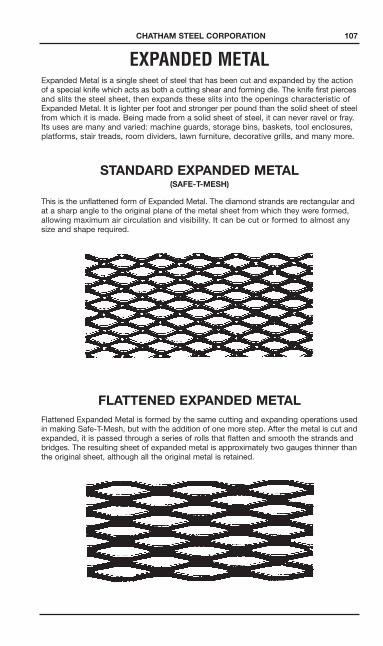
EXPANDED METALExpanded Metal is a single sheet of steel that has been cut and expanded by the actionof a special knife which acts as both a cutting shear and forming die. The knife first piercesand slits the steel sheet, then expands these slits into the openings characteristic ofExpanded Metal. It is lighter per foot and stronger per pound than the solid sheet of steelfrom which it is made. Being made from a solid sheet of steel, it can never ravel or fray.Its uses are many and varied: machine guards, storage bins, baskets, tool enclosures,platforms, stair treads, room dividers, lawn furniture, decorative grills, and many more.
STANDARD EXPANDED METAL(SAFE-T-MESH)
This is the unflattened form of Expanded Metal. The diamond strands are rectangular andat a sharp angle to the original plane of the metal sheet from which they were formed,allowing maximum air circulation and visibility. It can be cut or formed to almost anysize and shape required.
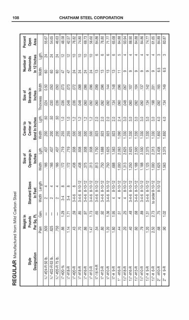
FLATTENED EXPANDED METALFlattened Expanded Metal is formed by the same cutting and expanding operations usedin making Safe-T-Mesh, but with the addition of one more step. After the metal is cut andexpanded, it is passed through a series of rolls that flatten and smooth the strands andbridges. The resulting sheet of expanded metal is approximately two gauges thinner thanthe original sheet, although all the original metal is retained.
CHATHAM STEEL CORPORATION 107
108 CHATHAM STEEL CORPORATIONREGULA
RM
anuf
actu
red
from
Mild
Car
bon
Ste
el
Weigh
tIn
Size
ofCe
nter
toSize
ofNu
mbero
fPe
rcent
Style
Pounds
Standard
Sizes
Opening
sin
Center
ofStrand
sin
Diam
onds
Open
Design
ation
PerS
q.Ft.
InFeet
Inches
Bond
InInches
Inches
In12
Inches
Area
Plai
nG
alv.
Wid
thLe
ngth
Wid
thLg
th.
Wid
thLg
th.
Thic
knes
sW
idth
Wid
thLg
th.
13 ⁄16"-#
24-R
50lb
..5
00—
24
.166
.437
.200
.50
.024
0.50
6024
55.6
713 ⁄16"
-#22
-R63
lb.
.625
—2
4.1
66.4
37.2
00.5
0.0
30.0
5060
2454
.65
13 ⁄16"-#
20-R
75lb
..7
50—
24
.166
.437
.200
.50
.036
.050
6024
46.6
311 ⁄4"
-#20
-%.8
61.
293-
48
.172
.719
.255
1.0
.036
.073
4712
48.5
811 ⁄4"
-#18
-R1.
141.
713-
48
.172
.719
.255
1.0
.048
.073
4712
42.5
711 ⁄2"
-#20
-R.4
3.5
93-
4-6
8.4
38.9
38.5
001.
2.0
36.0
7224
1076
.82
11 ⁄2"-#
18-R
.70
.85
3-4-
68-
10-1
2.4
38.9
38.5
001.
2.0
48.0
8824
1074
.80
11 ⁄2"-#
16-R
.86
.97
3-4-
68-
10-1
2.3
75.9
38.5
001.
2.0
60.0
8624
1069
.73
11 ⁄2"-#
13-R
1.47
1.73
3-4-
68-
10-1
2.3
13.9
38.5
001.
2.0
92.0
9624
1056
.60
13 ⁄4"-1
6H-
R.5
4.6
53-
4-6
8-10
-12
.813
1.75
0.9
232.
0.0
60.0
9913
684
.86
13 ⁄4"-#
13-R
.80
.92
3-4-
68-
10-1
2.7
501.
688
.923
2.0
.092
.096
136
76.8
013 ⁄4"
-#10
-R1.
201.
363-
4-6
8-10
-12
.750
1.62
5.9
232.
0.0
92.1
4413
671
.77
13 ⁄4"-#
9-R
1.80
1.95
48-
10-1
2.6
881.
563
.923
2.0
.134
.148
136
65.6
81"
-#16
-R.4
4.5
14
8-10
-12
1.00
02.
063
1.09
02.
4.0
60.0
9611
584
.88
11 ⁄2"-#
18-R
.20
.25
48-
10-1
21.
313
2.62
51.
330
3.0
.048
.067
9.0
493
.94
11 ⁄2"-#
16-R
.40
.48
3-4-
68-
10-1
21.
250
2.62
51.
330
3.0
.060
.107
9.0
488
.90
11 ⁄2"-#
13-R
.60
.68
3-4-
68-
10-1
21.
188
2.50
01.
330
3.0
.092
.104
9.0
484
.88
11 ⁄2"-#
10-R
.79
.89
3-4-
68-
10-1
21.
188
2.50
01.
330
3.0
.092
.137
9.0
484
.86
11 ⁄2"-#
9-R
1.20
1.31
3-4-
68-
10-1
21.
125
2.37
51.
330
3.0
.134
.142
9.0
474
.77
11 ⁄2"-#
6-R
2.50
2.73
toor
der8
-10-
121.
000
2.31
31.
330
3.0
.198
.201
9.0
461
.65
2"-#
10-R
.68
.75
8-10
-12
1.62
53.
438
1.85
04.
0.0
92.1
656.
53
84.8
92"
-#9-
R.9
01.
021.
563
3.37
51.
850
4.0
.134
.149
6.5
383
.87

CHATHAM STEEL CORPORATION 109FLATTENED
Man
ufac
ture
dfr
omM
ildC
arb
onS
teel
Weigh
tIn
Size
ofCe
nter
toFinished
Numbero
fPe
rcent
Style
Pounds
Standard
Sizes
Opening
sin
Center
ofTh
ickness
Diam
onds
Open
Design
ation
PerS
q.Ft.
InFeet
Inches
Bond
InInches
InInches
In12
Inches
Area
Plai
nG
alv.
Wid
thLe
ngth
Wid
thLg
th.
Wid
thLg
th.
Thic
knes
sW
idth
Lgth
.13 ⁄16"
-#24
-F48
lb.
1.48
5—
24
1.08
51.
459
1.20
01.
520
.019
6023
39.4
513 ⁄16"
-#22
-R61
lb.
1.60
6—
24
1.08
51.
459
1.20
01.
520
.024
6023
39.4
513 ⁄16"
-#20
-F73
lb.
1.72
7—
24
1.08
51.
459
1.20
01.
520
.029
6023
39.4
511 ⁄4"
-#20
-F1.
831.
243-
48
1.09
41.
688
1.25
51.
031
.030
4711
.64
46.4
911 ⁄4"
-#18
-F1.
111.
653-
48
1.09
41.
688
1.25
51.
031
.040
4711
.64
39.4
211 ⁄2"
-#20
-F1.
401.
513-
48
1.37
51.
000
1.50
01.
260
.029
249.
570
.73
11 ⁄2"-#
18-F
1.66
1.88
3-4-
68-
10-1
21.
281
1.00
01.
500
1.26
0.0
3924
9.5
67.7
011 ⁄2"
-#16
-F1.
821.
003-
4-6
8-10
-12
1.25
01.
000
1.50
01.
260
.050
249.
559
.62
11 ⁄2"-#
13-F
1.40
1.62
3-4-
68-
10-1
21.
250
1.00
01.
500
1.26
0.0
7024
9.5
55.5
813 ⁄4"
-16
H-F
1.51
1.71
3-4-
68-
10-1
21.
750
1.75
01.
923
2.10
0.0
4813
5.7
74.7
713 ⁄4"
-#14
-F1.
631.
753-
4-6
8-10
1.68
81.
813
1.92
32.
120
.061
135.
6269
.72
13 ⁄4"-#
13-F
1.75
1.86
3-4-
68-
10-1
21.
688
1.78
21.
923
2.10
0.0
7013
5.62
72.7
513 ⁄4"
-#9-
F1.
711.
863-
4-6
8-10
-12
1.56
31.
688
1.92
32.
120
.120
135.
6262
.65
1"-#
16-F
1.41
1.50
48
1.87
52.
250
1.09
02.
562
.048
114.
684
76.7
911 ⁄2"
-#16
-F1.
381.
444
81.
063
2.75
01.
330
3.20
0.0
489
3.8
81.8
411 ⁄2"
-#14
-F1.
461.
563-
4-6
81.
063
2.75
01.
330
3.20
0.0
609
3.8
81.8
411 ⁄2"
-#13
-F1.
571.
683-
4-6
81.
063
2.75
01.
330
3.20
0.0
709
3.8
78.8
111 ⁄2"
-#9-
F1.
141.
283-
4-6
8-10
-12
1.00
02.
563
1.33
03.
200
.110
93.
747
75.7
8
EXPA
NDEDMETA
LWALK
WAY,SKYWALK
&GRATING
110 CHATHAM STEEL CORPORATIONTh
isis
the
mos
tec
onom
ical
way
top
utst
reng
th,
safe
tyan
dno
n-sl
ipsu
rfac
esun
der
foot
.It
isno
tp
re-a
ssem
ble
d,
not
wel
ded
,b
utst
urd
y,so
lidst
eel,
cut
and
stre
tche
dfr
oma
sing
lep
late
.
Inst
alla
tion
isd
one
qui
ckly
and
easi
lyb
yw
eld
ing
orb
oltin
g.Irr
egul
arsh
apes
are
easy
tocu
tan
dp
lace
.Th
ene
atap
pea
ranc
e,lo
nglif
e,an
dfr
eed
omfr
omre
pai
rof
fere
db
yop
enm
esh
floor
ings
mea
nm
aint
enan
ceco
sts
are
ata
min
imum
.
Weigh
tIn
Size
ofCe
nter
toSize
ofNu
mbero
fPe
rcent
Style
Pounds
Standard
Sizes
Opening
sin
Center
ofStrand
sin
Diam
onds
Percent
Design
ation
PerS
q.Ft.
InFeet
Inches
Bond
InInches
Inches
In12
Inches
Area
Plai
nG
alv.
Wid
thSW
DLen
gth
LWD
Wid
thLg
th.
Wid
thLg
th.
Thic
knes
sW
idth
Wid
thLg
th.
3.0
lb.-R
3.00
3.20
3-4-
5-6
8-10
-12
.938
3.43
81.
333
5.33
0.1
83.2
619
2.25
70-7
63.
14lb
.-R3.
143.
343-
4-6
101.
625
4.87
52.
000
6.00
0.2
50.3
086
2.00
70-7
44.
0lb
.-R4.
004.
303-
4-5-
68-
10.9
383.
438
1.33
35.
330
.215
.297
92.
2562
-70
4.27
lb.-R
4.27
4.46
3-4-
68-
101.
036
2.96
91.
412
4.00
0.2
43.3
008.
53.
0056
-62
5.0
lb.-R
5.00
5.50
4-5-
68-
10.8
133.
375
1.33
35.
330
.250
.327
92.
2549
-54
6.25
lb.-R
6.25
6.85
3-4-
64-
8-12
.813
3.37
51.
412
5.33
0.3
12.3
478.
52.
2552
-60
7.0
lb.-R
7.00
7.50
410
0".8
133.
375
1.41
25.
330
.312
.388
8.5
2.25
55-6
4
GRATING—REGULA
RM
anuf
actu
ring
from
Mild
Car
bon
Ste
elan
dTy
pe
5052
-H32
Alu
min
um
Weigh
tIn
Size
ofCe
nter
toSize
ofNu
mbero
fPe
rcent
Style
Pounds
Standard
Sizes
Opening
sin
Center
ofStrand
sin
Diam
onds
Open
Design
ation
PerS
q.Ft.
InInches
Inches
Bond
InInches
Inches
In12
Inches
Area
Plai
nG
alv.
Wid
thSW
DLen
gth
LWD
Wid
thLg
th.
Wid
thLg
th.
Thic
knes
sW
idth
Wid
thLg
th.
Colu
mn
Inse
rt2.
69—
6-8-
1096
1.25
06.
125
1.50
05.
330
.183
.264
8—
65Ra
iling
Inse
rt2.
69—
3627
1.25
06.
125
1.50
05.
330
.183
.264
8—
65Sh
eets
2.69
—36
-48-
7296
1.25
06.
125
1.50
05.
330
.183
.264
8—
65
GRATING—REGULA
RM
anuf
actu
red
from
Mild
Car
bon
Ste
elan
dTy
pe
5052
-H32
Alu
min
um
Uses:
Pla
ntru
nway
s,ca
twal
ks,
and
wor
king
pla
tfor
ms.

CHATHAM STEEL CORPORATION 111
WELDED STEEL GRATING & TREADSOpen steel flooring is manufactured of square-edge strips for your safety. This gives it anon-slip surface and permits light and air to pass through.
It is made in several types: Standard Welded, Heavy Welded, Serrated, and is useduniversally where strong rigid flooring is desired.
We can supply for immediate delivery. Welded Type in panels 24" and 36" wide and inlengths up to 24'. It can also be furnished in 36' lengths for special applications. Standardstock is painted black, but can easily be galvanized when required.
Steel flooring can be cut to specified sizes, as requested.
When ordering open steel flooring, specify the following:1. Type of grating.2. Depth and thickness of bearing bars.3. Dimensions of area or areas to be covered. Unless otherwise specified, our standard
tolerance of 1/4" will apply.4. Span (direction of bearing bars).5. Finish — mill unless otherwise specified.6. Type of fasteners — if required.7. Complete shipping instructions.8. Drawing showing grating area and supports.9. Specify whether drawings for approval and/or erection drawings are required.
The best type for use where floors are subject to extreme corrosion or moisture —chemical plants, breweries and other process industries. There are no cracks,open joints, or holes in bars.
All/weld gratings are furnished with 5/16" twisted square cross bars.
TypeW/B
TypeW/F
TypeW/D
TypeW/DF
SP
EC
IAL
OR
DE
RS
TAN
DA
RD
Approved for all general purposes.
Same as Type W/B but with closecross bars for conditions wheremore steel area is required.
Close bearing bars. Best for heavypublic traffic, or where smalleropenings or increased carryingcapacity are required.
With closer cross bar and bearingbars. For conditions requiringgreatly reduced net opening.
SERRATEDALL-WELD GRATINGWhere moisture, oil or greaseare present, an extra measureof safety can be provided byusing serrated All-Weld gratingas pictured here.

112 CHATHAM STEEL CORPORATION
*1⁄4 thickness only on all I-bar sizes.
GRATING — Continued
STEELWEIGHTS PER SQUARE FOOT
ALUMINUMWEIGHTS PER SQUARE FOOT
SIZE
WELD
ED
PRESSURELO
CKED
RIVETED
NO.
W/B
W/D
W/F
W/DF
BD
FDF
XX
ZZ
BB
DD
BT
BTL
UUJ
JK
113 ⁄4
x11 ⁄8
4.1
5.0
5.0
5.9
3.9
4.8
4.6
5.5
7.0
8.6
7.0
7.9
9.0
6.5
213 ⁄4
x13 ⁄1
65.
87.
26.
78.
15.
77.
06.
47.
77.
89.
09.
912
.38.
59.
710
.48.
03
13 ⁄4x1
1 ⁄85.
26.
46.
17.
35.
26.
46.
07.
29.
311
.58.
011
.110
.57.
54
13 ⁄4x1
3 ⁄16
7.5
9.3
8.4
10.2
7.5
9.3
8.3
10.1
10.2
11.9
13.3
16.5
10.5
9.6
9.5
13.2
12.5
9.0
511 ⁄2
x11 ⁄8
6.3
7.9
7.2
8.8
6.3
7.9
7.1
8.7
11.4
14.2
9.0
12.6
12.0
8.5
611 ⁄4
x13 ⁄1
69.
111
.310
.012
.29.
111
.39.
912
.212
.714
.816
.520
.711
.410
.211
.015
.314
.710
.57
11 ⁄2x1
1 ⁄87.
49.
38.
310
.27.
69.
58.
710
.613
.917
.210
.014
.213
.59.
58
11 ⁄2x1
3 ⁄16
10.8
13.5
11.7
14.4
11.0
13.7
12.1
14.8
15.3
17.8
20.0
25.0
12.3
10.9
12.5
17.4
16.8
12.0
913 ⁄4
x13 ⁄1
612
.515
.613
.416
.512
.715
.813
.816
.917
.820
.823
.329
.415
.513
.914
.019
.418
.813
.510
21 ⁄4x1
3 ⁄16
14.1
17.7
15.0
18.6
14.3
17.9
15.4
19.0
20.5
23.8
26.5
33.2
16.4
14.5
17.0
23.3
22.9
16.0
1121 ⁄4
x13 ⁄1
615
.819
.816
.720
.716
.020
.017
.121
.122
.726
.529
.837
.317
.215
.118
.525
.425
.017
.512
21 ⁄2x1
3 ⁄16
17.4
21.9
18.3
22.8
17.7
22.1
18.8
23.2
25.0
29.3
33.1
41.4
18.0
15.7
20.0
27.8
27.1
19.0
SIZE
WELD
ED
PRESSURELO
CKED
RIVETED
NO.
BD
FDF
BB
DD
BT
BTL
XX
ZZ
IBID
IFIDF
UUJ
JK
113 ⁄4
x11 ⁄8
1.4
1.7
1.7
2.0
2.6
3.1
1.9
2.4
2.7
3.3
2.3
213 ⁄4
x13 ⁄1
62.
02.
52.
22.
73.
84.
72.
73.
12.
93.
33.
82.
83
13 ⁄4x1
1 ⁄81.
92.
32.
22.
63.
44.
22.
52.
73.
83.
82.
74
13 ⁄4x1
3 ⁄16
2.6
3.3
2.9
3.5
5.0
6.2
3.7
3.4
3.5
4.1
1.9
2.3
2.1
2.5
3.2
4.5
4.5
3.3
511 ⁄4
x11 ⁄8
2.3
2.8
2.6
3.1
4.2
5.2
3.1
3.1
4.3
4.3
3.1
611 ⁄4
x13 ⁄1
63.
24.
03.
54.
36.
57.
64.
13.
74.
45.
12.
32.
82.
52.
93.
85.
25.
33.
87
11 ⁄2x1
1 ⁄82.
83.
43.
23.
85.
26.
33.
73.
44.
94.
93.
58
11 ⁄2x1
3 ⁄16
3.9
4.8
4.3
5.2
7.4
9.2
4.4
3.9
5.3
6.2
2.6
3.2
2.8
3.4
4.3
6.0
6.0
4.4
913 ⁄4
x13 ⁄1
64.
55.
64.
95.
98.
610
.85.
64.
96.
17.
23.
03.
73.
33.
94.
86.
76.
84.
910
21 ⁄4x1
3 ⁄16
5.1
6.3
5.5
6.7
9.8
12.1
5.8
5.1
7.1
8.2
3.4
4.2
3.7
4.4
5.8
8.0
8.0
5.8
1121 ⁄4
x13 ⁄1
65.
77.
06.
17.
411
.013
.56.
15.
47.
89.
13.
84.
64.
04.
96.
48.
78.
86.
412
21 ⁄2x1
3 ⁄16
6.3
7.8
6.7
8.1
12.2
14.8
6.4
5.7
8.6
10.0
4.0
4.9
4.2
5.1
7.2
9.7
9.6
7.0

CHATHAM STEEL CORPORATION 113
STAIR TREADSStair treads are fabricated in any grating type, complete with carrier plates at each endof tread for bolting to stair stringers. Tread nosing makes the leading edge of each stepstand out clearly. Serrated treads are recommended to eliminate hazardous footingconditions.
Treads can be made to any specification required.
11 ⁄4"
Che
cker
edP
late
Ste
eltr
ead
son
ly
11 ⁄4"
Ab
rasi
ve
Ste
elan
dA
lum
inum
Trea
ds
11 ⁄4"
Cor
ratr
ed
Alu
min
umTr
ead
son
ly*S
teel
Trea
ds
13 ⁄4"
upto
and
incl
udin
g11 ⁄4
"d
eep
trea
ds
21 ⁄4"
for
othe
rsA
lum
inum
Trea
ds
21 ⁄4"
alld
epth
s7 ⁄1
6"o/
hole
&sl
otfo
r3⁄8
"o/
bol
t.
TABLE
OFSTA
NDARDTREADWIDTHSFO
R:
Ste
elgr
atin
gw
ithch
ecke
red
pla
teno
sing
.A
lum
inum
grat
ing
with
corr
atre
dno
sing
.(T
read
sw
ithab
rasi
veno
sing
sar
e1 ⁄8
"le
ssin
wid
th)
RECTA
NGULA
R(DIM
ENSIONA)
RIVETED
BW/B
IBHOLE
CENTERS
TYPEK(1 ⁄
16B.B.)
63 ⁄821 ⁄2
67 ⁄8
71 ⁄241 ⁄2
81 ⁄8
83 ⁄441 ⁄2
91 ⁄2
97 ⁄871 ⁄2
103 ⁄4
111 ⁄8
71 ⁄212
1 ⁄8
121 ⁄4
71 ⁄213
3 ⁄8

114 CHATHAM STEEL CORPORATION
Bea
ring
Bar
Sp
an
Siz
e2'
-0"
2'-6
"3'
-0"
3'-6
"4'
-0"
4'-6
"
U38
624
717
212
696
7613 ⁄4
x11 ⁄8
D.0
95.1
51.2
16.2
95.3
74.4
86C
386
308
258
220
194
171
D.0
76.1
19.1
73.2
34.3
08.3
89
U57
837
025
818
814
411
513 ⁄4
x13 ⁄1
6D
.095
.151
216
.295
.374
.486
C57
846
238
633
128
925
7S
pan
D.0
76.1
19.1
73.2
34.3
08.3
895'
0"5'
6"6'
0"
U68
643
930
422
417
113
510
991
7611 ⁄8
x11 ⁄8
D.0
72.1
11.1
59.2
19.2
88.3
66.4
51.5
47.6
73C
686
549
457
392
343
305
275
250
228
D.0
57.0
90.1
29.1
76.2
31.2
93.3
60.4
34.5
18
U10
2965
945
933
825
720
316
413
511
413 ⁄1
6x3 ⁄1
6D
.072
.111
.159
.219
.288
.366
.451
.547
.673
C10
2982
468
658
751
445
841
237
534
3S
pan
D.0
57.0
90.1
29.1
76.2
31.2
93.3
60.4
34.5
186'
6"7'
0"
U10
2768
647
635
026
821
217
214
211
910
187
11 ⁄4x1
1 ⁄8D
.057
.090
.129
.176
.231
.291
.358
.433
.520
.608
.704
C10
2785
871
661
353
647
743
039
035
833
030
6D
.046
.072
.104
.141
.183
.233
.288
.349
.416
.487
.565
LOAD&DEFLECTIONS
SAFE
LOADTA
BLE
FORSTEELGRATING
(Based
onaminimum
allowablefib
erstress
of18,000
P.S.I.)
U—
Saf
eun
iform
load
inp
ound
sp
ersq
uare
foot
.C—
Saf
eco
ncen
trat
edlo
adin
pou
nds
per
foot
ofw
idth
.D—
Def
lect
ion
inin
ches
.

CHATHAM STEEL CORPORATION 115
U16
0810
2871
652
640
331
825
821
317
915
213
111 ⁄4
x13 ⁄1
6D
.057
.090
.129
.176
.231
.291
.358
.433
.520
608
.704
C16
0812
8510
7391
880
371
664
458
553
649
545
9S
pan
D.0
46.0
72.1
0414
1.1
83.2
33.2
88.3
49.4
16.4
87.5
658'
-0"
9'0"
U15
4498
768
650
538
730
624
820
517
214
912
896
7511 ⁄2
x11 ⁄8
D.0
47.0
75.1
06.1
4719
2.2
43.3
00.3
65.4
33.5
06.5
87.7
74.9
78C
1544
1235
1029
883
772
687
619
563
515
475
441
386
342
D.0
38.0
59.0
87.1
17.1
54.1
95.2
41.2
89.3
47.4
06.4
70.6
14.7
77
U23
2114
8510
3175
858
145
837
130
726
022
219
114
511
511 ⁄2
x13 ⁄1
6D
.047
.075
.106
.147
.192
.243
.300
.365
.433
.506
.587
.774
.978
C23
2118
5615
4713
2511
5910
3192
884
477
371
466
358
151
5D
.038
.059
.087
.117
.154
.195
.241
.289
.347
.406
.470
.614
.777
U31
5120
1614
0110
2978
862
250
541
635
129
925
919
715
513 ⁄4
x13 ⁄1
6D
.042
.064
.092
.126
.165
.208
.258
.310
.371
.435
.506
.664
.838
C31
5125
2121
0018
0015
7514
0012
6011
4510
4996
989
978
670
0D
.033
.052
.074
.101
.132
.167
.206
.249
.297
.347
.403
.527
.667
U41
1626
3318
2913
4410
2981
365
954
646
039
333
925
820
421 ⁄4
x13 ⁄1
6D
.036
.056
.081
.111
.144
.183
.226
.273
.325
.384
.447
.580
.732
C41
1632
9227
4523
5120
5818
2816
4614
9613
7012
6611
7510
2791
4D
.029
.045
.064
.088
.115
.145
.180
.217
.259
.303
.353
.460
.583
U52
0933
3223
1416
7013
0210
2883
568
958
349
642
832
725
921 ⁄4
x13 ⁄1
6D
.032
.050
.072
.098
.127
.162
.199
.241
.287
.338
.393
.512
1.6
46C
5209
4167
3473
2916
2604
2314
2082
1892
1733
1601
1487
1301
1157
D.0
26.0
39.0
57.0
79.1
02.1
29.1
60.1
94.2
30.2
70.3
14.4
10.5
18
U64
3241
1528
5820
9916
0912
7110
2985
072
061
352
940
532
021 ⁄2
x13 ⁄1
6D
.028
.044
.064
.088
.116
.145
.180
.217
.260
.305
.354
.465
.586
C64
3251
4742
8636
7332
1428
5825
7123
3821
4119
7718
3616
0714
29D
.023
.036
.051
.071
.092
.116
.144
.173
.207
.242
.282
.369
.467
2'-0
"2'
-6"
3'-0
"3'
-6"
4'-0
"4'
-6"
5'-0
"5'
-6"
6'-0
"6'
-6"
7'-0
"
CONTINUATIONOFPA
GE114
Sp
ans
torig
htof
vert
ical
line
NO
TR
EC
OM
ME
ND
ED
.
SAFE LOAD TABLE FOR STEEL GRATING(Based on a minimum allowable fiber stress of 18,000 P.S.I.)U—Safe uniform load in pounds per square foot.C—Safe concentrated load in pounds per foot of width.D—Deflection in inches.

NOTES
116 CHATHAM STEEL CORPORATION