89-97 tbird/cougar/mark viii odometer gear replacement · '89-97 tbird/cougar/mark viii...
TRANSCRIPT

www.OdometerGears.com
'89-97 Tbird/Cougar/Mark VIII Odometer Gear Replacement
http://www.supercoupeperformance.com/Instructions/Speedo%20-%20Odo%20Repair%20Inst..htm
Replacement odo gears can be found under the "Hoods / Body Kits / Miscellaneous" sections of www.SuperCoupePerformance.com.

*********************************************************************************************
Please read the first few steps carefully as these are our most common questions we receive after a client has performed a repair and the odometer still does not work.
The reason the original gear or gears have failed is that they are made of urethane and lubricated with petroleum grease. This combination breaks down the urethane into a waxy substance which flakes and breaks away. This will also leave a waxy film and deposits on the shafts, gears, housing and peg on the pods.
* Work smart, meaning have a clean area to work and the proper tools to perform the repair. General tools that will be needed depending on the vehicle are small standard screwdriver, small Phillips screwdriver, assortment of torx drivers, diagonal cutters (dikes), 1/4" socket set are just a few of the items that may be needed.
* No grease is needed with the new gears. Our gears are made using Celcon® which has graphite mixed into the material and does not require any additional lubricant.
* Make sure that you have blown the speedometer and odometer assembly clean with high pressure compressed air or compressed air in a can. If using the can of compressed air be sure to use the entire can to blow all areas clean. Even if you think that you have found all of the broken pieces you still need to perform this step.
* Wipe the area around the gears, any shaft or shafts that the gears may ride on, the motor shaft and the peg on the pod that the small gear spins on clean, using a clean cloth and rubbing alcohol. Any residue left over from the old gears can allow the new gears to stick and not allow the odometer to work.
* On units that use a gear and pod combination: install the gears into the housing first and then install the motor assembly. Before installing the screws that secure the motor and circuit board use a small standard screw driver and rock the tenths digit of the odometer up and down. This will help to seat the gears into place and allow the motor assembly to seat fully.

Failure of the 1989-97 Thunderbird Odometer Gear happens due to excessive heat and age. You can see the damage caused by the heat. The plastic gears got so hot the surface shows bubbles which weakened the gears and eventually
caused the gear or gears to break and the odometer to stop working.
The odometer part of the speedometer has a small electric motor which drives a 16 tooth cam gear also called carrier gear (POD) which then drives a 20 tooth intermediate gear which drives
the odometer and trip odometer.
16 tooth Carrier Gear (POD)

20 tooth Intermediate Gear
Now that you know what the cause of the odometer failure is lets take you through replacing
these gears.
BEFORE WE BEGIN, IT IS ABSOLUTELY CRUCIAL THAT YOU KEEP THIS UNIT CLEAN WHILE WHILE WORKING ON IT. WE RECOMMEND YOU HAVE COMPRESSED AIR AVAILABLE TO BLOW OFF THE PARTS AS YOU DISASSEMBLE AND REASSEMBLE EVERYTHING! KEEPING EVERYTHING
SUPER CLEAN WILL RESULT IN A SUCCESSFUL JOB.
Removal of the instrument cluster bezel surrounding the cluster is necessary. Removal of the instrument cluster from the car is not necessary. You will need to remove the clear plastic instrument cluster cover first. Once this cover is off you can just pluck the speedometer assembly from the car
Before you start you need to refer to the Ford Shop Manual for removal instructions.
In addition to the Ford Shop Manual here are a few tips.

Remove the lower panel below the steering wheel.
Remove the vent ducting behind the lower panel.
Loosen the 4 nuts holding the steering column to the dash frame. Lower the steering column about 1 inch.
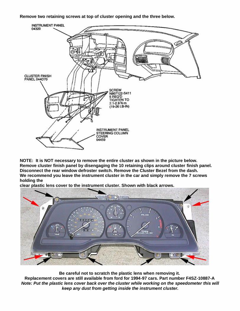
Remove two retaining screws at top of cluster opening and the three below.
NOTE: It is NOT necessary to remove the entire cluster as shown in the picture below. Remove cluster finish panel by disengaging the 10 retaining clips around cluster finish panel. Disconnect the rear window defroster switch. Remove the Cluster Bezel from the dash. We recommend you leave the instrument cluster in the car and simply remove the 7 screws holding the clear plastic lens cover to the instrument cluster. Shown with black arrows.
Be careful not to scratch the plastic lens when removing it. Replacement covers are still available from ford for 1994-97 cars. Part number F4SZ-10887-A
Note: Put the plastic lens cover back over the cluster while working on the speedometer this will
keep any dust from getting inside the instrument cluster.

If you are removing the instrument cluster from the dash (which is NOT RECOMMENDED) then remove the 4 screws holding the cluster to the dash. Shown with red arrows.
Tilt the cluster and remove the two electrical connectors and boost vacuum line
(Supercharged only) going into the back of the cluster.

The speedometer is held in place by three pressure contacts. Grab the Speedo and pull it out of the cluster. Once you have removed the Speedo find a flat clean area to work.

Note: Before you remove the needle and using a pencil mark the location of the needle. (You want to just mark the very edge of the speedometer face where the needle naturally rests. When
the repair is done you will need to line up the needle to this mark.)
DO NOT PRY UP ON THE NEEDLE TO REMOVE! This is the trickiest part of the job. Start by first removing the trip meter reset button. The needle is pressed onto a shaft that is extremely thin. It feels like a pretty tough metal, but you need to be careful here. Do not pull straight up. Do not put any torque on the shaft. Grip the speedometer needle at the center and rotate counter clockwise, until it hits an internal stop and then gently continue to rotate the needle while also gently applying a small amount of upwards tension at the same time. Friction is all that is holding the needle to the shaft. Keep turning and applying a small amount of upwards tension until the needle comes off. Do not force it.

After the needle is removed flip it over and remove the 3 screws holding the plastic housing to the faceplate.
Shown with black arrows.
Note: The trip odometer spring will fall out when you separate the face plate from the housing so do not lose it.
Once the speedometer housing is removed from the speedometer faceplate you can optionally remove the 4 screws
holding the green board to the housing. This step is not necessary to replacing the Odometer

gears. Shown with red arrows.
Next remove the 2 screws holding the Odometer motor to the housing. Once you remove the screws be careful of the two wires, blue and black. Shown with black
arrows. Using a pick or small flat blade screwdriver disconnect the wires from the housing.
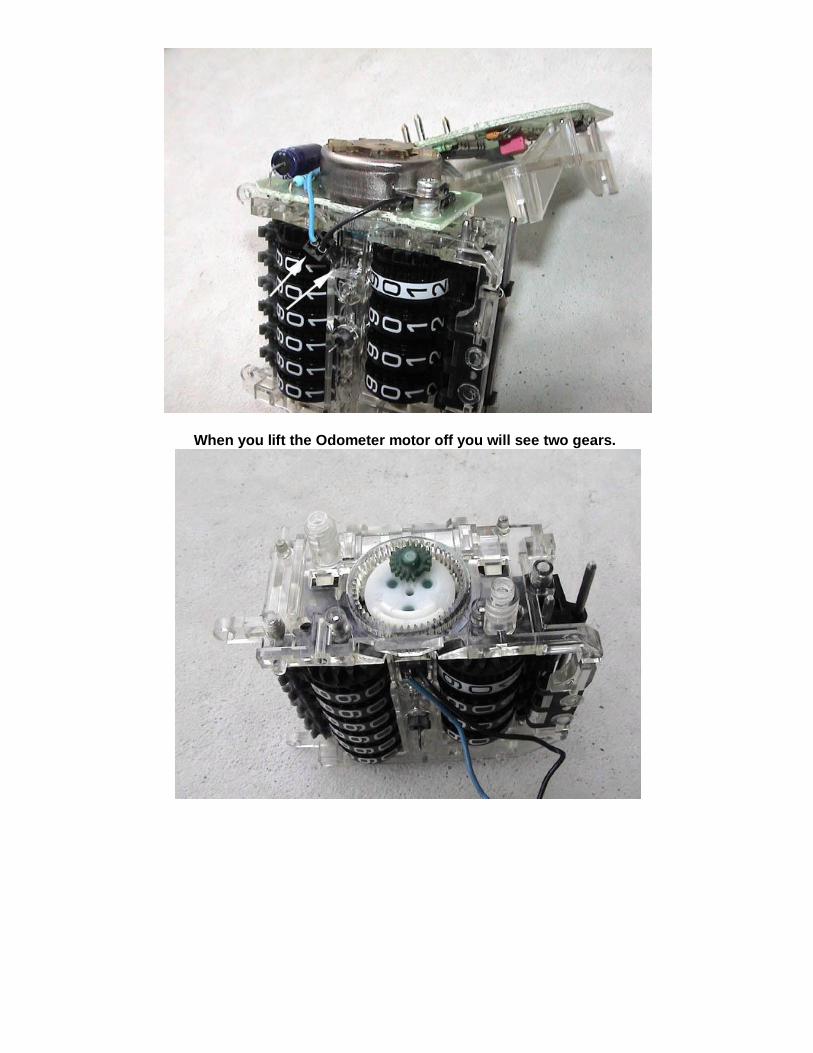
When you lift the Odometer motor off you will see two gears.

Remove the two gears. Now use a shop air compressor to aggressively blow the internal parts of
the speedometer clean. Now go back and inspect the black gears on the end of the odometer and trip meter shafts for any debris. Even the smallest fragment will cause the odometer to not work once reassembled. Also be sure to use the air compressor on the motor side as well. The motor
has the shaft that goes through the pod. There is a tiny gear at the bas e of the shaft that must be free of debris as well.
Fit the two new gears together as shown.

Place the gears into the housing and rotate the gears until they seat in the housing.

When installing the Odometer motor making sure the gears mesh together. Gently rock the
odometer gears back and forth when installing the motor and tightening the screws. If they become tight then you are binding the gears and the odometer will not work. Check your gear
positions and try again.

Reinstall the two screws holding the Odometer motor onto the housing. Reconnect the Odometer motor electrical connector.
Install the green board back on the housing with the 4 screws if you removed it. Before reconnecting the Faceplate and housing back together verify the trip odometer is
working. Pull back on the lever that resets the trip odometer. It should reset without binding.
Any problems with resetting the trip odometer and you have misaligned the gears when you put it back together.
Go back and verify the gears are seated and fully meshed. Install the trip odometer reset spring over the lever as shown.
Then align the trip odometer reset lever pin and lever back together.
Reconnect the 3 screws holding the housing to the faceplate.
Note: Do not over tighten the screws as you will strip the plastic threads in the faceplate. Snug

but not too tight.
Now we reattach the speedometer needle. Press the needle over the pin as shown. Then adjust the needle so it aligns back at your pencil mark you made earlier. When reinstalling
the Speedo needle, make sure you gently push down evenly on the center hub of the needle. Once it is on firmly, use the internal stop points at max speed and 0 mph/kph to realign the
needle with your mark you made earlier. Gently rotate the needle while holding the center of the needle. Once the needle points to your mark then the speedometer is set to the previous
calibration.
Reinstall speedometer back in the instrument cluster.
Then re-install the cluster bezel and tighten the steering back up. Re-install the duct and lower plate.
Take the car for a test drive and verify the odometer and trip odometer are working again.
Additional speedometer calibration procedure:

Before you reinstall the faceplate and the bezel an additional speedometer calibration verification procedure can be done.
Note: Tighten the 4 steering nuts back before you drive the car. Using a GPS like the one shown, or a friend to help you, one can verify MPH speed between the GPS and your speedometer needle. Drive the car over a level road for 1/2 mile at a 30mph while your friend watches the GPS display it's MPH. If your MPH is off then stop, shut off the car and pull the speedometer out of the instrument cluster. If the GPS displayed 35mph while you kept the car at a steady 30mph you will adjust the needle forward 5mph. Using a thin screw driver inserted behind the faceplate to hold the needle from rotating adjust the speedometer needle to any hash mark and push the needle up 5mph. Reinstall the speedometer back into the cluster and retest. The shop manual lists a speedometer error factor. The odometer cannot be recalibrated or
adjusted.
www.OdometerGears.com