83821 mark iv elementary & connection diagram
TRANSCRIPT

GEK-83821
GE Drive Systems
Instructions
MARK IV SPEEDTRONICTM TURBINE CONTROL ELEMENTARY and PANEL CONNECTION DIAGRAM READING AID


GEK 83821
MARK IV SPEEDTRONIC *
TURBINE CONTROL ELEMENTARY
and
PANEL CONNECTION DIAGRAM
READING AID
* Trademark of GENERAL ELECTRIC COMPANY, U.S.A.

Issued: September, 1984
(GEK - 83821)
NOTICE
The information herein does not purport to cover all details or variations in equipment nor to provide for every possible contingency to be met in connection with installation, operation and maintenance. Should further information be desired or should particular problems arise which are not covered sufficiently for the purchaser's purposes, the matter should be referred to General Electric Company, Drive Systems Operations, 1501 Roanoke Boulevard, Salem, Virginia, USA, 24153.
NOTICE
This document contains proprietary information of General Electric Company, USA and is furnished to its customer solely to assist that customer in the installation, testing, and/or maintenance of the equipment described. This document shall not be reproduced in whole or in part nor shall its contents be disclosed to any third party without the written approval of General Electric Company, Drive Systems Operations, 1501 Roanoke Boulevard, Salem, Virginia 24153, U.S.A.
-a-

MARK IV SPEEDTRONIC Control Elementary/Panel Connection Diagram Reading Aid
PREFACE
This reading aid is intended to help the user understand the methods employed to represent data in the control system elementary and the panel connection diagram. It is not intended to explain any control philosophies or methodologies.
This publication is intended for use by personnel with at least a basic understanding of electrical circuitry and control systems.
This document is designed to be used in conjunction with the customer Control System Elementary and Panel Connection Diagram to explain the pictorial representation of hardware and software used in the MARK IV SPEEDTRONIC turbine control panel. The examples used in the text refer to the elementary and connection diagram for graphics illustrations. The user should have the elementary and assembly diagram available before attempting to understand the examples in this instruction.
-b-

MARK IV SPEEDTRONIC Control Elementary/Panel Connection Diagram Reading Aid
TABLE OF CONTENTS
Section Topic
PREFACE . . . . . . . . . . . .................... b TABLE OF CONTENTS . . . . . . .................... i-l FIGURE INDEX . . . . . . . . .................... i-3
I. CONTROL SYSTEM ELEMENTARY
A. PURPOSE . . . . . .
B. GENERAL INTRODUCTORY
1. SHEET INDEX . . 2. NOMENCLATURE .
. . . . . . . . . . . . . . . . . . . . I-l
. . . . . . . . . . . . . . . . . . . . I-l
SHEETS . . . . . . . . . . . . . . . . I-2
....................
.................... I-2 I-2 I-2 I-4 I-4 I-5 I-8 I-8 I-8 I-9 I-11 I-12 I-13 I-13 I-13 I-14 I-14 I-15 I-15 I-15 I-16 I-16 I-16 I-17 I-17 I-19 I-19 I-19 I-20 I-20 I-22 I-22 I-22 I-22 I-23
3. BERG JUMPER ASSIGNMENTS ................ a. BERGJUMPERSYMBOL ................
4. SYMBOLSANDTERMS ................... a. HARDWARE SYMBOLS AND TERMS ............
1. TERMINALBOARDS ............... 2. TURBINE CABLE/CONNECTOR SYMBOL ....... 3. RELAY CONTACT AND COIL NOTATION ....... 4. POSITION AND LIMIT SWITCH SYMBOL NOTATION . . 5. BLOCK SYHBOLOGY ...............
b. WIRING SYMBOLOGY ................. 1. RIBBONCABLE ................ 2. DISCRETE WIRING ............... 3. TWISTED NON-SHIELDED WIRING ......... 4. SHIELDED WIRING ...............
C. SOFTWARE SYMBOLS AND TERMS. ........... 1. LADDER DIAGRAM SYMBOLS AND TERMS ......
a. SOFTWARE CONTACTS ........... b. SOFTWARE COILS .............
1 SOFTWARE COUNTER ......... 2. SOFTWARE INPUT .......... 3. SOFTWARETIMER ..........
C. SOFTWARERUNG ............. 2. ALGORITHM SYMBOLS AND TERMS .........
a. BLOCK NOTATION ............. b. CIRCLE NOTATION ............ C. CONTROL CONSTANTS NOTATION ....... d. CONTACT GATED INPUT AND OUTPUT SIGNALS . e. ALGORITHM SAMPLE EXPLANATION ......
5. OPERATOR INTERFACE. ............... 6. SWITCH AND DEVICE DEVELOPMENTS .......... 7. ONE-LINE DIAGRAMS ................
a. HARDWARE ONE-LINE DIAGRAMS ............ b. SOFTWARE ONE-LINE DIAGRMIS ............
PaKe
. l- 1

MARK IV SPEEDTRONIC Control Elementary/Panel Connection Diagram Reading Aid GEK 83821
TABLE OF CONTENTS (Continued)
Section Topic Page
I. c. ADDITIONAL NOTES ON INTERPRETATION . . . . . . . . . . I-23
1. MEMBmE SWITCH INPUTS ........... . . . . . I-24 2. SOFT-SWITCH INPUTS ............. . . . . . I-25 3. OPERATING SYSTEM AND RECOVERY LADDER DIAGRAM . . . . . I-25 4. CONTACT INPUTS ............... . . . . . I-26 5. VIDEO DISPLAY MESSAGES - NORMAL ....... . . . . . I-26 6. VIDEO DISPLAY MESSAGES - ALARM ....... . . . . . I-26 7. CONTACT OUTPUTS ............... . . . . . I-27
II. PANEL CONNECTION DIAGRAM . . . . . . . . . . . . . . . . . . 11-l
A. PURPOSE OF THE PANEL CONNECTION DIAGRAM . . . . . . . . . . II-1
B. SYMBOLS . . . * . . . * . . . . . . . . . . . . .
1. MODULE SYMBOLS ............... . . . . . 11-l 2. CARDSYMBOLS ................ . . . . . II-3 3. TERMINAL BOARD SYMBOLS ........... . . . . . II-5 4. WIRING SYMBOLOGY .............. . . . . . II-5 5. GENERAL DEVICE SYMBOLS ........... . . . . . II-6
C. CROSS-REFERENCING . . . . . . . . . . . . . . . . . . . . . II-9
1. INTER-MODULE CROSS-REFERENCING . . . . . . . . . . . . II-9 2. INTERNAL MODULE CROSS-REFERENCING . . . . . . . . . . . II-10 3. RELAY CONTACT/COIL CROSS-REFERENCING . . . . . . . . . II-11
D. SHEET-BY-SHEET DESCRIPTION . . . . . . . . . . . . . . . . . II-11
. . . . .
1. 2. 3. 4. 5. 6. 7. 8. 9. 10. 11.
12.
TITLE SHEET ...................... II-11 INDEX ......................... II-11 NOMENCLATURE ..................... II-11 OPERATOR INTERFACE .................. II-12 CONTACT INPUTS .................... II-12 RELAY MODULES ..................... II-12 ANALOG I/O MODULES .................. II-12 28VDC DISTRIBUTION MODULE ............... II-12 THERMOCOUPLE INPUT MODULES .............. II-12 RTD INPUT MODULE ................... II-12 <R>,<S>,<T> CONTROLLER ELECTRONICS MODULES ...... II-13 a. <R> CONTROLLER .................. II-13 b. <S> CONTROLLER .................. II-13 C. <T> CONTROLLER .................. II-13 <C> COMMUNICATOR MODULE ................ II-13
II-1
l- 2

MARK IV SPEEDTRONIC Control Elementary/Panel Connection Diagram Reading Aid GEK 83821
TABLE OF CONTENTS (Continued)
Section Topic Page
II. D. (Continued)
13. <RDM> RELAY DRIVER MODULE ............... II-13 14. <OPM> OPERATOR INTERFACE MODULE ............ II-13 15. <CRT> VIDEO DISPLAY .................. II-13 16. <PTR> PRINTER (PANEL MOUNTED) ............. II-13 17. <CLIMl-2> COMMUNICATION LINE ISOLATION MODULES .... II-13 18. <SYNCH> SYNCHRONIZING INTERFACE MODULE ........ II-13 19. <FDl-4> FLAME DETECTORS ................ II-13 20. <INV> BLACK START INVERTER .............. II-14 21. <PDH> POWER DISTRIBUTION MODULE ............ II-14
E. CONCLUSION ......................... II-14
FIGURE INDEX
Figure Topic PaRe
ELEMENTARY READING AID:
I-l HARDWARE DEVICE SYMBOLS ................ I-6 I-2 HARDWARE DESCRIPTION ABBREVIATIONS .......... I-7 I-3 CODES FOR PRESSURE AND LIMIT SWITCH CONTACTS ..... I-10 I-4 HARDWARE BLOCK SYMBOL ABBREVIATIONS .......... I-11 I-5 SOFTWARE BLOCK FUNCTIONAL ABBREVIATIONS ........ I-18
PANEL CONNECTION DIAGRAM READING AID:
II-1 HARDWARESYMBOLS ................... II-7 II-2 BLOCK SYMBOL TEXT ABBREVIATIONS ............ II-8
. l- 3

MARK IV SPEEDTROIIC Control Elementary/Panel Connection Diagram Reading Aid GEK 83821
i-4

MARX IV SPEEDTRONIC Control Elementary Reading Aid GEK-83821
I.B. GENERAL INTRODUCTORY SHEETS
The control system elementary is separated into two sections, the introductory section, commonly referred to as the "front sheets", and the functional section. The front sheets have numbers which use an alphabetic character as the first character. The functional sheets have numbers which use a numeric character as the first character.
The front sheets include general data for use in understanding the remainder of the elementary. This includes such items as a table of contents, nomenclature lists, one-lines, and symbol definitions for quick reference.
I.B.l. SHEET INDEX, sheets AOO,AOl
The Control System Elementary is organized functionally. The sheets used for each of the functions are listed in the SHEET INDEX. The general overall organization covers inputs to the control, sequencing functions, control functions, and outputs from the control in that order. The SHEET INDEX should be used to identify the sheets involved in a particular function.
The basic organization is structured for use on multiple applications, so some of the functions listed in the SHEET INDEX may not be actually utilized on a particular control application. However, all the standard structured sheet references are included in the index to be compatible with any functional changes which could occur after shipment of the panel. Special functions and the sheet locations are added as the application requires.
I.B.2. NOMENCLATURE, sheets A02 - Axx
The signal and device names used in the elementary are defined on the NOHENCLATURE sheets for user reference in understanding the functions represented. The names are listed in alpha-numeric order. Each name is accompanied by the sheet number where it originates and a definition of its meaning.
I.B.3. BERG JUMPER ASSIGNMENTS, sheets BOl - B21
The hardware used in the control panel is structured so that the same hardware components may be used for similar functions. To provide the flexibility required to use components for different functions, and to provide the ability to alter system hardware performance parameters, many of the electronics modules are designed with jumper selectable characteristics. The desired characteristics are selected by placing slide-on jumpers in the appropriate positions on the electronics modules. These jumpers are referred to as "berg jumpers".
I-2
GEK-83821 MARK IV SPEEDTRONIC Control Elementary Reading Aid
I.B.3. BERG JUMPER ASSIGNMENTS, sheets B01 - B21 (continued)
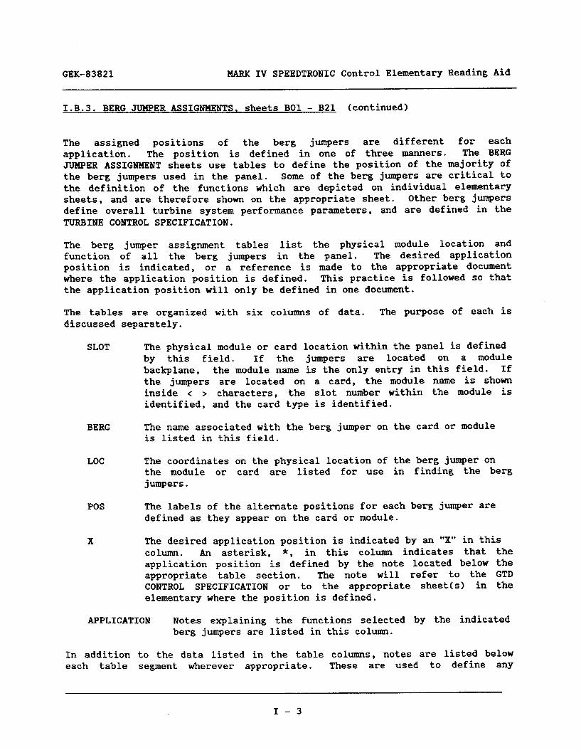
The assigned positions of the berg jumpers are different for each application. The position is defined in one of three manners. The BERG JUMPER ASSIGNMENT sheets use tables to define the position of the majority of the berg jumpers used in the panel. Some of the berg jumpers are critical to the definition of the functions which are depicted on individual elementary sheets, and are therefore shown on the appropriate sheet. Other berg jumpers define overall turbine system performance parameters, and are defined in the TURBINE CONTROL SPECIFICATION.
The berg jumper assignment tables list the physical module location and function of all the berg jumpers in the panel. The desired application position is indicated, or a reference is made to the appropriate document where the application position is defined. This practice is followed so that the application position will only be defined in one document.
The tables are organized with six columns of data. The purpose of each is discussed separately.
SLOT The physical module or card location within the panel is defined by this field. If the jumpers are located on a module backplane, the module name is the only entry in this field. If the jumpers are located on a card, the module name is shown inside < > characters, the slot number within the module is identified, and the card type is identified.
BERG The name associated with is listed in this field.
the berg jumper on the card or module
LOC The coordinates on the physical location of the berg jumper on the module or card are listed for use in finding the berg jumpers.
POS The labels of the alternate positions for each berg jumper are defined as they appear on the card or module.
X The desired application position is indicated by an "X" in this column. An asterisk, *, in this column indicates that the application position is defined by the note located below the appropriate table section. The note will refer to the GTD CONTROL SPECIFICATION or to the appropriate sheet(s) in the elementary where the position is defined.
APPLICATION Notes explaining the functions selected by the indicated berg jumpers are listed in this column.
In addition to the data listed in the table columns, notes are listed below each table segment wherever appropriate. These are used to define any
I-3

MARK IV SPEEDTRONIC Control Elementary Reading Aid GEK-83821
I.B.3. BERG JUMPER ASSIGNMENTS, sheets BOl - B21 (continued)
additional hardware application data associated with the card or module. Examples of this data include such items as RAM and PROM chip definitions, and definition of daughter board requirements.
I.B.3.a. BERG JUMPER SYMBOL
Berg jumpers are shown in the elementary so they appear as a jumper connecting two points. The points are shown as open circles drawn at the end of wiring linework, or in the middle of a line. Each point is labelled with the appropriate position abbreviation. The name of the jumper also appears in the vicinity of the jumper symbol. The actual symbol for the jumper is an offset straight line which has 45 degree angled segments drawn to the open circles to indicate the points that are connected by the jumper.
Refer to sheet 27B of the elementary for an example. At coordinates 691, a berg jumper is shown which selects the type of input sensor characteristic for the circuit. The jumper is labelled as "SA" and the available positions are labelled as WPU" (magnetic pick-up) and "TTL" (transistor-transistor logic input).
I.B.4. SYMBOLS AND TERMS
The next section of elementary sheets deals with the symbols and terms used in the elementary. Certain symbol definitions are provided within the elementary itself because they are used frequently. Other symbol definitions and guidelines appear only in this reading aid.
Both hardware and software functions are presented symbolically on the control elementary sheets. The software functions are distinguished from the hardware functions by enclosing the software portions within a solid border and labelling the enclosure with the word “SOFTWARE”.
Hardware functions are separated into two categories. Category one is the hardware contained in the modules within the panel. This hardware is enclosed in solid lines and labelled with the module designator symbol for the appropriate module. Refer to elementary sheet B30 for the definition of the module designator symbols.
Hardware category two includes those functions which are not performed by the control panel modules. Each individual device in this category has a location which is defined by one of the symbols listed on sheet B29 of the elementary. The absence of a location symbol indicates that the device is mounted within the control panel.
I-4

GEK-83821 MARK IV SPEEDTRONIC Control Elementary Reading Aid
I.B.4. SYMBOLS AND TERMS (Continued)
A general discussion of symbols and terms is presented next. Specific practices and interpretations of symbology for each section of the elementary will be presented in other sections of the reading aid.
I.B.4.a. HARDWARE SYMBOLS AND TERMS
The control system elementary shows the details for the connection of external hardware devices to the control panel. These hardware devices include sensors, contacts, and other devices which are located external to the control panel. Each of these devices is represented on the control system elementary by one of the hardware symbols shown in figure I-l. Each device also is accompanied by a location symbol which defines the particular piece of external equipment where the device is located. These location symbols are listed on sheet B29 of the elementary. An additional special symbol with provision for variable data is used to define motor control center locations. Refer to sheet B31 of the elementary for the symbol graphics and data definition.
Sheet B29 also lists some of the commonly used abbreviations which describe hardware devices and their operation. Other abbreviations for hardware description are included in figure I-2.
Within the panel, each module has a symbolic name. This name is enclosed in < > characters, and is derived from the full functional name of the module. A list of these symbolic module names, or module designations, is shown on sheet B30 of the elementary.
I-5

MARK IV SPEEDTRONIC Control Elementary Reading Aid GEK-83821
Figure I-l. - HARDWARE DEVICE SYMBOLS
- INDUCTOR
--I+ CAPACITOR
RESISTOR / - RESISTIVE HEATER
a FUSE
/ST7 CASE GROUND
TRAUSFORMER
RECEPTACLE / OUTLET
-o_ MOTOR -&- SWITCH
+ OVERLOAD HEATER
+- STAB CONNECTOR
DISCRETE WIRING
' CABLED WIRING/ RIBBON CABLE (X IS Jk'MBER OF CONDUCTORS)
T TWISTED WIRING
c-
TWISTED WIRING SHOWN INDIVIDUALLY (X IS GROUP NUNBER)
OPERATIONAL AMPLIFIERS
-K TRANSISTOR (PNP)
-L EARTH GROUND
-u=- x LOGIC INVERTER
-#- LIGHT
-L 4- PUSHBUTTON - N.O.
--q~p PUSHBUTTON - N.C.
d-- CIRCUIT BREAKER
1 CONNECTION DOT
(X) TERMINAL BOARD POINT
(X IS POINT NUMBER)
Jx-b (‘%a) GTD JACK/CABLE
CONNECTOR (REFER TO ELEM. ~29)
r-I , ' SHIELD WIRING
t SHIELD
I_ I I TWISTED SHIELDED I ., WIRING
7 - SHIELD DRAIN WIRE
--c t7
--Lb
it- , .
-
XY A
--2z B
c
a---
L r
DIODE
ZENER DIODE
TRANSISTOR- (NPN)
BUS COMMON
RELAY DRIVER / LIGl<T DRIVER
RELAY COIL WITH DIODE SUPPRESSION AND INDICATING LIGHT
RELAY COIL / SOLENOID
CONTACT - N.O.
CONTACT - N.C.
TEST POINT
?IETAL TERMINAL BOARD JCMPER
(CONNECTING POINTS u, v)
BERG JUMPER (JLTIPER xy SHOWN IN POSITION B)
THERMOCOUPLE
OSCILLATOR
PHOXE JACK
I -6

GEK-83821 MARK IV SPEEDTRONIC Control Elementary Reading Aid
Figure I-2. - HARDWARE DESCRIPTION ABBREVIATIONS
ABBREVIATION DESCRIPTION
AL AM AR ASW C CA CB CR DL DS FU HR INST. L M MA
HOV NC NO PB R RE REC RH T TB TD TDC TDDO TDO TDPU TDl TDO TP V VM W
(AIL) (BIL) (GIL) (RIL) (WIL)
AC light ammeter AC receptacle (outlet) AC switch capacitor cable remote prefix circuit breaker diode DC light DC switch fuse hand reset instantaneous inductor motor milliamps milliammeter metal oxide varistor normally closed normally open pushbutton resistor supervisory (remote) prefix rectifier rheostat control power transformer terminal board time delay time delay close time delay drop out time delay open time delay pick up time delay to a logic "1" time delay to a logic "0" test point volts voltmeter watts watt-hour meter amber indicating light blue indicating light green indicating light red indicating light white indicating light
I-7

MARK IV SPEEDTROPIC Control Elementary Reading Aid GEK-83821
I.B.4.a.l. TERMINAL BOARDS
Terminal boards are supplied, within the panel and within the hardware modules, for the termination of wires from external sources. Each terminal board point appears as an open circle embedded into the wiring symbology linework. Each terminal board point is labelled with a terminal board name and point number. The point number data is shown in parentheses above or beside the terminal board symbol.
Module terminal board names are derived from the functional name of the module in which it is mounted.
Refer to sheet 04G for an example. At coordinates 17P, the connection for the wire supplying 125VDC to the 45FTX field contacts is shown. The wire is connected to RTB-1 (Relay module Terminal Board number 11, point number 10.
Terminal board names for equipment external to the control panel are assigned by the manufacturer of the particular equipment, and are shown in the elementary for reference in connecting that equipment to the control panel.
I.B.4.a.2. TURBINE CABLE/CONNECTOR SYMBOL
A special symbol is used to represent the cable connections used to connect GTD cabled wiring to the appropriate panel/cab device. The symbol is a filled-in terminal board symbol, and it has a dual interpretation. The symbol and its meaning are shown on sheet B31 of the elementary.
I.B.4.a.3. RELAY CONTACT AND COIL NOTATION
The relay coils and their contacts are identified with a name and a location designator. The relays are given functional names, such as 4X-1, RA, PER&l, or 45FTX.
The location designator is a five character alphanumeric string, composed of the relay module number, an R, the absolute row number, the slot number, and the location within that slot. The absolute row number is the row number independent of module divisions; i.e., the first row of module number 2 is referred to as row 4. Each slot has space for three relays stacked vertically; A is the top position and C is the bottom position.
An example of a location designator is 1RlKA (refer to sheet 046, coordinates 31~). This relay, named 45FTX, is located in relay module 1, <RELAYl>, absolute row 1, slot K, position A (top).
I -8

GEK-83821 MARK IV SPEEDTRONIC Control Elementary Reading Aid
I.B.4.a.3. RELAY CONTACT AND COIL NOTATION (Continued)
Relay coils and contacts are shown on the sheets where they are used. Since each relay has only a finite number of contacts, the coils and contacts need to be cross-referenced to assure proper application. Beside, or below, each coil are a set of five digit alphanumeric numbers denoting the location where each contact is used. The number is composed of the sheet number and line number, on the referenced sheet, where the contact is shown. Below, or beside, each contact, a similar five digit alphanumeric number is shown (enclosed in brackets, [ I) indicating the location of the appropriate relay coil.
I.B.4.a.4. POSITION AND LIMIT SWITCH SYMBOLS AND NOTATION
Position and limit switches are shown as relay contacts. Under the functional name for the device is a descriptive code consisting of two lower case letters plus a number when required. The first letter indicates the contact condition corresponding to the end position of the device as indicated by the second letter. If a number is used, it indicates the percent of travel from the end position.
The contacts are shown in the position they return to normally when power is removed, or after a normal shutdown. If no position is defined by this, the contacts will be shown normally open.
A list of the codes is shown in figure I-3. An example of the use of this notation follows.
Example 1. 33CB-1 bo
The compressor bleed/bypass valve (33CB-1 device) limit switch contacts shown are coded as "closed" when the bleed/bypass valve is "open" (end position).
Example 2. 33cs ad
The contacts are "open" only when the starting clutch (33CS device) is fully "disengaged" (end position).
I-9
MARK IV SPEEDTRONIC Control Elementary Reading Aid GEK-83821
I.B.4.a.4. POSITION AND LIMIT SWITCH SYMBOLS AND NOTATION (continued)
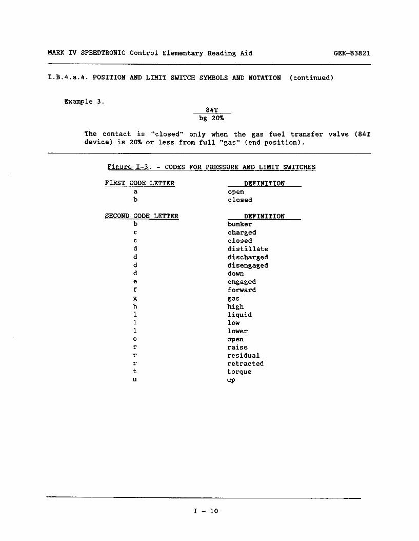
Example 3. 84T
bg 20%
The contact is "closed" only when the gas fuel transfer valve (84T device) is 20% or less from full "gas" (end position).
Figure I-3. - CODES FOR PRESSURE AND LIMIT SWITCHES
FIRST CODE LETTER DEFINITION
; open closed
SECOND CODE LETTER b C
C
d d d d e f
: 1 1 1 0
r r r t U
DEFINITION bunker charged closed distillate discharged disengaged down engaged forward gas high liquid low lower open raise residual retracted torque up
I - 10

GEK-83821 MARK IV SPEEDTRONIC Control Elementary Reading Aid
I.B.4.a.5. BLOCK SYMBOLOGY
Boxes or rectangles with text inside are used to represent functions in a concise manner. The text is an abbreviation or explanation of the hardware function which is being performed. Refer to the table in figure I-4 for definitions of the types of abbreviations used.
Figure I-4. - ABBREVIATIONS USED IN HARDWARE BLOCK SYMBOLS
TEXT DESCRIPTION
A/D D/A L
MN
N 01 OR osc RD REG RECT SW
logic "and" logic "and" analog to digital converter digital to analog converter logic maximum select, output = greater of inputs minimum select, output = lesser of inputs multiplexer inverter optical isolator logic wOr" oscillator relay driver regulator rectifier switch
l/l
2/3
non-voting circuit, state of input determines state of output voting circuit, 2 of the 3 signals determine state of output
I - 11

MARK IV SPEEDTROPIC Control Elementary Reading Aid GEK-83821
I.B.4.b. WIRING SYMBOLOGY
Different types of wiring are used to interconnect the internal pieces of the control panel, and to connect the control panel to external devices. The appropriate type of wire is indicated on the control system elementary by the type of wiring symbology used.
Wires are labelled with wire numbers to identify the wires. All wires shown in the elementary are labelled underneath the wire linework with a DSD wire number. Wires connecting to external devices are labelled above the linework with a GTD wire number.
DSD wire numbers are placed below the wire linework. The basic wire number consists of three characters. The three characters are the x-y coordinates of the origin of the wire. If the wire run is shown in several segments, the origin is labelled with the three character wire number already discussed, and the additional segments are labelled with the same number prefixed with the sheet number of the origin segment. A cross-reference is placed beside the origin segment to define the sheet and x-y coordinates where each additional segment is shown.
Example: ! (231) [07D441 t . 056
In this example the wire originates at coordinates 05G of an elementary sheet. It is continued on sheet 07D at line number 44. On sheet 07D the wire number would define the sheet of origination and the sheet coordinates.
! 02C05G !
GTD wire numbers are shown above the linework for the wires. Each GTD wire number is enclosed by parentheses and is assigned per GTD standards. If any exceptions to the standard assignments are used, they are defined on sheet B31 of the elementary.
(245)
The GTD wire number in the example above is 245.
I.B.4.b.l. RIBBON CABLE
Ribbon cabled wiring is depicted by the use of solid lines with 45 degree angle turns and branches. The individual device outputs and inputs which are collected into the cable are depicted with a 45 degree angle line which connects the output or input "wire" to the cabled run; connectipn dots are not used. This technique is also utilized within symbols to
I - 12

GEK-83821 MARK IV SPEEDTROPIC Control Elementary Reading Aid
I.B.4.b.l. RIBBON CABLE (Continued)
symbolically consolidate similar runs and simplify the presentation of data. When the cabled run is crossed with a hash mark, the number beside the hash mark indicates the number of conductors in the ribbon cable.
Ribbon cables mate with card edge or backplane mounted connectors. These are shown on the hardware symbols as dashed rectangles. Each connector is labelled with the connector number and, if appropriate, the nomenclature for the card on which it is mounted.
Referring to sheet OlB, the operator input module <OPH> is connected to the communicator <C> by a ribbon cable which mates with connector JKA on the backplane of the communicator electronics module, and mates with connector JC on the HPIB card in the operator interface module <OPM>.
I.B.4.b.2. DISCRETE WIRING
Discrete wiring is depicted by the use of solid lines which connect straight into devices, and make turns at right angles on the elementary. No grouping is shown, and branching is shown using solid dots overlaying the wire joints. These dots are referred to as "connection" dots.
I.B.4.b.3. TWISTED NON-SHIELDED WIRING
Twisted non-shielded wiring is shown by drawing a line perpendicular to the wires which are twisted together. This perpendicular line extends below the lines for the wires and has arrowheads pointing at each of the wires which are twisted together. The line is labelled with a "T" to indicate twisting.
Refer to sheet 36A of the elementary for an example. The wires connecting the thermocouples to the thermocouple input module cTCM.R> are shown as twisted. In this particular example, the wiring is also denoted as being thermocouple wire through the use of notes.
Whenever it is not possible to show twisted wires so that both may be connected by the perpendicular arrowheaded designator, each wire is marked with the designator and a suffix is appended to the "T" to denote the grouping of the twisted wires.
I - 13

MARK IV SPEEDTRONIC Control Elementary Reading Aid GEK-83821
I.B.4.b.4. SHIELDED WIRING
Shielded wiring is depicted by the use of a dashed oval which overlays the wires which are shielded. When two or more wires are encircled by the same shielded wiring symbol, those wires are twisted together inside the shield.
Refer to sheet 27B. The wires connecting the pulse tach pick-ups (77NH-1,2,3) to the analog input module cAI0.3~ are shown as shielded.
The termination of the shield drain wire is defined by the routing of the wire which is connected to the bottom of the dashed oval symbol. In the example on sheet 27B, the shield for the portion of the shielded wire between the jack connectors and the ANALOG IO MODULE, is terminated at the shield bus bar in the ANALOG IO MODULE.
Shields for wiring routed through jack connectors, are jumpered together at a junction box. This collection of shields is then run to one of the pins in the jack, usually the last jack pin. The connection of the shield drain wire from the last pin in the cable is shown on sheet 44E of the elementary. The shield drain wires, which are handled in this manner, are labelled on the sheets where they appear with a GTD wire number of "E" followed by the lower of the GTD wire numbers associated with the wires which the shield covers. Referring to sheet 27B, the shield for device 77NH-1, shown at coordinates 41E, is labelled with GTD wire number (E2360).
I.B.4.c. SOFTWARE SYMBOLS AND TERMS
Software functions are enclosed within a solid border and labelled with the word "SOFTWARE". Each function is also labelled with the module designation of the processor which is executing the associated functional software.
Software functions are presented in two basic formats, ladder diagram format and algorithm format. The ladder diagram format is very similar to relay diagrams in structure and interpretation. The algorithm format is a flow diagram type of symbology.
I.B.4.c.l. LADDER DIAGRAM SYMBOLS AND TERMS
The ladder diagram format uses symbols such as contacts and coils to represent logic execution and memory locations (RAM). The interpretation of the contact sequences is similar to standard relay notation. The main difference is that microprocessors execute data in a sequential manner, therefore the order in which the contacts and coils are shown is the order in which the logic is interpreted. There are no relay races or simultaneous operations. Ladder diagram data is shown on the elementary in the order in which it is executed.
I - 14

GEK-83821 MARK IV SPEEDTRORIC Control Elementary,Reading..Aid
I.B.4.c.l.a. SOFTWARE CONTACTS
The symbols used in the ladder diagram format include the standard hardware symbols used for normally open and closed contacts. Each software contact is labelled with nomenclature which describes the functional use of the contact. Refer to elementary sheets A02 through A99 for nomenclature definitions.
Each software contact is associated with a software coil which is located in one of the processors. If a module designation symbol is shown next to a software contact, then the source of that data is the indicated processor. When the module designation symbol is omitted, then the software coil for that software contact is located in the processor indicated at the top of the software enclosure.
A cross-reference number is located in brackets below each software contact to identify the sheet on which the software coil is shown. Only the sheet number is used in this scheme for two reasons. Since the data must be shown in the order of execution, the relative position of a software coil may slide up or down the sheet as requirements change. Also, all coils are stacked in a column which can be easily scanned to locate the desired software coil.
I.B.4.c.l.b. SOFTWARE COILS
The symbol for a software coil is a large circle. Each software coil is labelled with a function name which is defined in the nomenclature sheets, A02 through A99. All software coils are shown within the software enclosure where they are created.
Cross references to the software contacts are shown on the right hand side of the ladder linework. The cross reference data consists of the sheet number where the signal is used, and if appropriate, the name of the rung or algorithm on the sheet. If the signal is used in a rung, then it is shown as a software contact in the ladder symbology. If the signal is used in an algorithm, then it is shown as a logic input signal.
The software coil symbol is additional functions.
I.B.4.c.l.b.l SOFTWARE COUNTER
The software counter symbol is and an additional input drawn labelled with an "E" is the
used with a letter inside to represent
the software coil symbol with a "C" inside into the bottom of the circle. The input input which causes the counter value to
increment on each closure of the indicated software contact string. The input labelled with an "R" is the reset input, which causes the count
I - 15

MARK IV SPEEDTRONIC Control Elementary Reading Aid GEK-83821
I.B.4.c.l.b.l SOFTWARE COUNTER (continued)
value to be reset to zero upon closure of its indicated software contact string. The output logic value of the counter transitions to the high, or "true", state when the count value equals the value written below and to the left of the symbol.
1.B 4.c.l.b.2. SOFTWARE INPUT
The software input coil is drawn the same as the software coil, but the state of the signal is determined by a hardware circuit and an input mask. Normally, the software coil is "picked-up" when the associated hardware supplies the appropriate voltage to the input circuits. The software coil is "dropped-out" when the appropriate voltage is removed from the input circuits. This relationship between the hardware circuit and the software coil state may be inverted, or reversed, by changing the input mask. Whenever the input mask has been changed to invert the input/output relationship, an "I" is placed inside the coil symbol.
I.B.4.c.l.b.3. SOFTWARE TIMER
The software timer symbol is the software coil symbol with a "T" inside. The timer starts timing when the input contact string is closed. The timer output transitions to the true state when the accumulated time equals the value specified below the timer symbol. The timer and its _ output logic state are reset whenever the input contact string is opened. Refer to L26QTlA software coil on sheet 02A as an example.
I.B.4.c.l.c. SOFTWARE RUNG
A string of software contacts and the resulting software coil (or timer, or counter) is called a RUNG. Each rung represents a segment of program code which establishes the state of the indicated functional software device.
I - 16

GEK-83821 MARK IV SPEEDTRONIC Control Elementary Reading Aid
I.B.4.c.2. ALGORITHM SYMBOLS AND TERMS
The algorithm format of representing software functions is a form of software functional flowchart. It uses blocks and circles with text and text abbreviations, contacts, timers, and other software symbols. These symbols are connected by lines with arrow heads to indicate direction of signal flow.
The symbology for each algorithm is enclosed within a dashed rectangular border. The algorithm name is stated in the top left hand corner of the algorithm border. This name is composed of the basic algorithm name, the modification number, and "xx" in place of the revision number. "XX" is used because the revision code is not related to the functionality of the algorithm. Functionally descriptive text is usually placed below the algorithm name.
An index of the algorithms, which may be included in each application, is shown on elementary sheets B40 and B41. The index lists the basic algorithm name, description, elementary sheet location where the algorithm symbol is shown, and the identification of the processor which actually performs the function.
Sampling rate data is located within the algorithm border at the bottom of each dashed rectangle. The sampling rate is the time interval at which execution of the particular algorithm is requested within the processor. A sampling rate of 0.25 SEC indicates that the algorithm is executed 4 times per second.
I - 17

MARK IV SPEEDTRONIC Control Elementary Reading Aid GEK-83821
Figure I-5. - SOFTWARE BLOCK FUNCTIONAL ABBREVIATIONS
ABBREVIATION
A*B
AND
EN
F<C>
F<R>
F<S>
F<T>
f(xxx)
INV -1
MAX SEL
PIED
RED SEL
HIN
WIN SEL
MOMENT
OR
z-1
DESCRIPTION
logic output is "1" when the Boolean equation involving inputs A and B is satisfied.
logic "and"
enable
function of processor C
function of processor R
function of processor S
function of processor T
function of Boolean logic expression xxx
sign change, (+ to -1 or (- to +>
maximum select function
maximum select function
median select function
median select function
minimum select function
minimum select function
momentary
logic *'or-
one time cycle delay, output = input from previous execution
I - 18

GEK-83821 MARK IV SPEEDTRONIC Control Elementary Reading Aid
I.B.4.c.2.a. BLOCK NOTATION
Blocks are boxes, or rectangles, with descriptive text, or text abbreviations, which define the function being presented. A table of abbreviations and their associated function is shown in figure I-S.
I.B.4.c.2.b. CIRCLE'NOTATION
Circles, with mathematical notation inside, are used to symbolize mathematical operations performed within the algorithms. The operation performed by each is defined by the particular mathematical symbols contained within the circle. Typical operations include summation, subtraction, multiplication, and division.
I.B.4.c.2.c. CONTROL CONSTANTS NOTATION
The algorithms use application dependent data for calculation of control curves, protective limits, and other parameters such as response time constants. These types of data are collectively referred to as *'CONTROL CONSTANTS". The functional nomenclature for each control constant is shown inside an elongated oval or rectangle located just outside the dashed algorithm border. Each control constant is considered as an input signal for the subject algorithm.
Control constants are segregated into two categories. Category one is the FIELD ADJUSTABLE control constant. This type of constant is programmed to an initial value in the factory, and customer authorized personnel may change the value interactively on the job site. The elongated oval symbol is used to identify this category of control constants.
The second category of control constants is the FACTORY ADJUSTABLE type. This type is programmed to an initial value at the factory and may not be changed by customer personnel at the job site. The elongated rectangle is used to identify this category of control constants. Examples of the elongated oval and elongated rectangle are shown on elementary sheet B31 for convenient reference.
I.B.4.c.2.d. CONTACT GATED INPUT AND OUTPUT SIGNALS
Some of the data inputs and data outputs from algorithms are drawn with contacts inserted into the linework. The contacts help to represent the functional use of the input/output signals.
I - 19

MARK IV SPEEDTRONIC Control Elementary Reading Aid GEK-83821
I.B.4.c.2.d. CONTACT GATED INPUT AND OUTPUT SIGNALS (Continued)
Input data signals generally use the contact notation to indicate whether the input signal is used or not used by the algorithm. A closed contact indicates that the input data signal is used by the algorithm. An open contact indicates that the signal is not used by the algorithm; no default value is substituted, the input is just omitted from the functional calculation.
Output data signals generally use the contact notation to indicate whether the output signal will be the calculated value or the default value of zero. A closed contact indicates that the value will be the value calculated by the algorithm. An open contact generally indicates that the value of the output signal is defaulted to zero.
At least one obvious exception to the these guidelines exists. That is the use of a form-C contact for either input or output signal gating. In this situation, the signal indicated by the closed contact is the signal used, and no default parameters are assumed.
I.B.4.c.2.e. ALGORITHM SAMPLE EXPLANATION
Refer to elementary sheet 26C for the ACCELERATION CONTROL algorithm. This algorithm will be explained as an example of how to interpret the functionality represented on the elementary sheets.
Sheet 26C is identified as a SOFTWARE sheet with controllers CR>, <S>, and <T> performing the algorithm. The algorithm name is FSRACCVl_OlXX which performs the ACCELERATION CONTROL function. The algorithm has a sampling rate of 0.25 SEC which means that it is executed 4 times per second.
The algorithm analyzes the input signals and selects the median of three values to be outputted to the FSR algorithm on sheet 26D for use in the fuel stroke reference calculation. The three inputs to the MEDIAN SELECT function are two control constants and a calculated value.
The first control constant shown is FSRMAX which is connected into the MEDIAN SELECT through an input labelled MAX LIMIT. Control constant FSRMAX is shown as a FIELD ADJUSTABLE constant by the use of the elongated oval symbol.
The second control constant shown is FSRMIN which is connected into the MEDIAN SELECT through an input labelled HIN LIMIT. Control constant FSRMIN is shown as a FIELD ADJUSTABLE constant by the use of the elongated oval symbol.
I - 20

GEK-83821 MARK IV SPEEDTRONIC Control Elementary Reading Aid
I.B.4.c.2.e. ALGORITHM SAMPLE EXPLANATION (continued)
The third input to the MEDIAN SELECT function is the calculated value. The turbine high pressure shaft speed, TNH, is subtracted from the sum of the previous value of TNH and the FIELD ADJUSTABLE control constant, FSKACCRl, since L83ACR2 signal is not used. If L83ACR2 signal is used, then the control constant used in this calculation would be determined by the state of the L83ACR2 signal. The output of this mathematical summation is an error signal proportional to the rate of change of TNH.
The L30F_ACN signal is a control signal which is "pick-up" when FSR (fuel stroke reference) is being controlled by the ACCELERATION CONTROL algorithm output signal FSRACC.
If the L30F_ACN signal is "dropped-out", then the rate error signal is multiplied by the factor expressed by FIELD ADJUSTABLE control constant FSKACCZ. The result of the multiplication is then summed with the FSR signal to create the third input to the MEDIAN SELECT gate. The sum created by the summation of FSR and the scaled rate error signal is a signal which will be greater than FSR for rate of speed changes which are less than the constant FSKACCRl (or FSKACCRZ). The sum will be less than FSR when the rate of speed change exceeds the constant FSKACCRl (or FSKACCR2).
When the LSOF_ACN signal is "picked-up", the current value of the rate error signal is multiplied by the FIELD ADJUSTABLE control constant, FSKACC3, and the result is subtracted from the product obtained by multiplying the previous value of rate error by the FIELD ADJUSTABLE control constant, FSKACC4. The resulting total is then added to FSR to create the third input to the MEDIAN SELECT function. The resulting effect is an integrating control signal.
To summarize, the acceleration control algorithm monitors the rate of change in the TNB signal, and produces a reference signal to the FSR minimum select function. When the rate of speed change (acceleration) exceeds the prescribed limit, the reference signal is reduced until it becomes the lowest signal entering the FSR algorithm. The acceleration control signal then causes the acceleration control algorithm to become an integrating control function. The acceleration control output signal may only vary between the limits established by the HIN and MAX inputs to the MEDIAN SELECT function.
I.B.5. OPERATOR INTERFACE
The operator interface module <OPM> and the cathode ray tube <CRT> provide the interface between the operator and the controls. The layout of the <OPM> is shown on elementary sheet COO. Notes on the operation of the auxiliary display are shown on elementary sheet COl.
I - 21

MARK IV SPEEDTRONIC Control Elementary Reading Aid GEK-83821
I.B.6. SWITCH AND DEVICE DEVELOPMENTS
Hardware developments for common switches and devices provide number data for reference on elementary sheet ClO.
I.B.7. ONE-LINE DIAGRAMS
One-line diagrams provide an overview of control functions. software one-line diagrams are included in the DO0 through elementary sheets.
I.B.7.a. HARDWARE ONE-LINE DIAGRAMS
Hardware one-line diagrams are provided for the controllers CR>, <S>, and CT>, sheet DOO, and for the communicator CC>, sheet Dol. These hardware one-lines depict the cards used in the electronics modules, and all the modules with which they interface. Each type of card is shown as a block with a card type identification inside. Use of multiple cards is indicated by a number in parentheses placed under the card type. Optional use of different quantities of a particular card type is indicated by placing the numbers, separated -by a .* 11 1, in parentheses under the card type. Modules are represented by block symbols with the module designation placed inside the block.
The interconnecting linework represents the interfacing wiring and cabling. Card to card communication via the local bus on the electronics module backplane is indicated by the connection from the card symbol to "L-BUS". Cabled connections to modules are represented by the lines with arrow heads indicating the direction of primary signal flow. A slash across the line, *t 11 1, accompanied by a number indicates the quantity of inputs or outputs being represented.
pin and point
Hardware and DKK series of
I - 22

GEK-83821 MARK IV SPEEDTRONIC Control Elementary Reading Aid
I.B.7.b. SOFTWARE ONE-LINE DIAGRAMS
Software one-line diagrams are provided for FSR (fuel stroke reference) generation and fuel control. Sheet DO2 is an overview of the algorithms and sensors which create the FSR signal. The individual algorithms are shown with block symbols. Each block is labelled with the algorithm name and elementary sheet number where the algorithm is presented. The algorithms for fuel stroke reference are performed by the controllers CR>, cS>, and CT>, unless otherwise indicated by the communicator designation, CC>, occurring inside the block symbol.
Sub-systems are described by enclosing algorithm blocks and hardware blocks within a dashed border. These sub-system packets show the signal generation beginning with the input sensor and terminating with the sub-system fuel stroke reference signal.
Sheet DO4 shows the individual fuel sub-systems which may be controlled by the FSR signal generated on sheet D02. Each fuel control sub-system uses a combination of software and hardware to achieve the required fuel control characteristics.
I - 23

MARK IV SPEEDTRONIC Control Elementary Reading Aid GEK-83821
I.C. ADDITIONAL NOTES ON INTERPRETATION
Although the general description of elementary symbology in section I.B. covers most functional conditions, some additional comments on specific elementary sections is included in this reading aid to enhance user understanding.
I.C.1. MEMBRANE SWITCH INPUTS (sheets OlA - OlC)
The operator input module <OPM> utilizes membrane switches to provide the operator interface to the controllers and the communicator.
Refer to elementary sheet OlA for examples of the membrane switch inputs. Membrane switch contacts are symbolized as pushbuttons on the hardware portion of the elementary sheet. Each input circuit has a corresponding circuit on the software portion of the sheet. The circuits are shown in pairs, with the hardware portion on the left side of the sheet and the software portion located on the same line on the right side of the sheet. The connection between the hardware portion and the software portion is represented using cable symbology.
The software portion contains a "PRE-SEQUENCER" function which performs two tasks. The PRE-SEQUENCER contains an inverter for each input signal. It also provides an input gatingiverification function. This gatingiverification function is symbolized by placing a contact in series with the inverter. Notation in parentheses above the contact indicates the particular function which must be satisfied before the input will be recognized or accepted.
Each hardware input signal is a logic level "1" (5 VDC) until the pushbutton is depressed to force the input signal level to "0" (0 VDC). The inverter in the software input circuit inverts the sense of the input signal. Therefore depressing the input pushbutton causes the software coil to be energized, provided that the gatingiverification logic is satisfied.
Example 1.
The STOP pushbutton is shown on sheet OlA. The PRR-SEQUENCER function indicates that this signal will only be accepted if the EXECUTE pushbutton is also depressed "OR" a communication link failure has occurred f(431EXEC + L3COMF). When the logic conditional statement is satisfied and the STOP pushbutton has been depressed, the software coil LISTPSEL is energized.
Example 2.
The ALARM SILENCE pushbutton is also shown on sheet OlA. The PRE-SEQUENCER function indicates that no conditional logic statement is used with this input. Therefore, depressing the ALARM SILENCE pushbutton immediately energizes the software coil L86ASIL (or L43ASIL, if applicable).
I - 24

GEK-83821 MARK IV SPEEDTRONIC Control Elementary Reading Aid
I.C.1. MEMBRANE SWITCH INPUTS (sheets OlA - OlC> (continued)
Example 3.
The OFF pushbutton is shown on sheet OlB. The PRE-SEQUENCER function indicates that the EXECUTE pushbutton must also be activated for the OFF input to be accepted. When OFF is depressed and then EXECUTE is depressed, the software coil L430SEL is energized.
I.C.2. SOFT-SWITCH INPUTS (sheets 01D - OlF)
The operator input module cOPI% has six pushbuttons,labelled FO, Fl, F2, F3, Fq, and F5, located beside the CRT (refer to sheet COO of elementary). The function of these pushbuttons is determined by the type of display function which appears on the CRT, and is defined on the CRT by that display function. Since these pushbuttons are defined by software, they are referred to as "soft-switches".
On the elementary sheets, the hardware portion shows a block for each display function. The display name and the function of each soft-switch is stated inside the display block border. The software portion shows the corresponding software coils on the same line as the input.
The function of the PRE-SEQUENCER for each input is defined by the notation inside the PRE-SEQUENCER blocks.
MOMENT. NOT USED SEC CODE
momentary not used in this functional display Security code must be entered to make pushbutton functional.
Example 1.
The FSR CONTROL display function is the first display block shown on elementary sheet OlD. Within this display, pushbutton F4 is defined as "FSR GAG RAISE" which has "momentary" action and energizes software coil L43FSRR when depressed.
I.C.3. OPERATING SYSTEM AND RECOVERY LADDER DIAGRAM (sheets OlG - OlZ>
The ladder diagram symbology is used to present some of the operating system, power-up recovery, and mode selection logic. Refer to individual sheet title blocks for purpose of each sheet.
I - 25

MARE IV SPEEDTRONIC Control Elementary Reading Aid GEK-83821
I.C.4. CONTACT INPUTS (sheets 02A - 022)
Guidelines for interpreting contact inputs have been discussed in previous sections of this reading aid. Refer to sections I.B. for details.
Example:
Referring to elementary sheet 02A, the LUBE OIL HEADER - HIGH TEMPERATURE trip contact, 26QT-lA, is identified by the location symbol as an *'accessory base mounted*' device. It is connected via optical isolator to software coil L26QTlA. The software coil is marked with an "I" to indicate inverted logical function. Whenever the lube oil temperature increases to the trip level, the normally closed field contact, 26QT-lA, will open and cause software coil L26QTlA to be energized.
I.C.5. VIDEO DISPLAY UESSAGES - NORMAL (sheets 17H - 17Q)
Certain messages normally appear on the CRT to describe the status of the control. These messages are divided into fields for definition of the message context. The logic which causes the various messages to be displayed is shown in ladder diagram format on the left of the message definition sheets. The corresponding message is shown on the same line on the right side of the sheet.
Example:
Referring to elementary sheet 17H, the **SHUTDOWN STATUS" message will appear in the TITLE FIELD when the software contact L30DSD is closed. The logic switch defines L30DSD and is shown as a ladder diagram rung on sheet 17R.
I.C.6. VIDEO DISPLAY MESSAGES - ALARM (sheets 18A - 18L)
Annunciator alarm messages are displayed on the CRT. The logic which causes the various messages to be displayed is shown in ladder diagram format on the left of the alarm message sheets. The corresponding message is shown on the same line on the right side of the sheet.
Example:
Referring to sheet 18A, ALARM2 is defined as '*HYDRAULIC PROTECTIVE TROUBLE*' and is activated by the L86HD ladder diagram rung on sheet 04B.
I - 26

GEK-83821 MARK IV SPEEDTRONIC Control Elementary Reading Aid
I.C.7. CONTACT OUTPUTS (sheets 20A - 202, 49A - 492)
Contacts from the relays, mounted in the relay modules, are used to drive solenoids (sheets 20A, etc.) and other external devices (sheets 49A, etc.). The relay driver circuits are located in the relay driver module, cRDM>. The relay driver circuits are either voting type, or non-voting type. The logic which activates each relay driver circuit is shown as a software contact on the appropriate elementary sheet. The output contacts are either shown on the same line as the relay coil, or are located elsewhere with appropriate cross-referencing between the coil and its contacts.
Voting type relay driver circuits are denoted by the "2/3" text located over the relay driver block symbol. These voting circuits receive a logic signal from each of the controllers, CR>, <S>, and CT>. The output is determined by agreement of two of the three inputs received.
Non-voting relay driver circuits are denoted by the "l/l" text located over the relay driver block symbol. The non-voting circuit receives a single input logic signal, and operates the relay accordingly.
The solenoid driver circuits utilize a solenoid filter circuit, labelled SSFG, which is shown in detail on sheet Cl0 of the elementary.
I - 27

MARK IV SPEEDTRONIC Control Elementary Reading Aid GEK-83821
USER NOTES
I - 28

GEK-83821 BARK IV SPEEDTRONIC Panel Connection Diagram Reading Aid
II. PANEL CONNECTION DIAGRAM
1I.A. PURPOSE OF THE PANEL CONNECTION DIAGRAM
The PANEL CONNECTION DIAGRAM is the drawing that documents the hardware used in the MARK IV SPEEDTRONIC* turbine control panel and how that hardware is interconnected. The term "connection diagram" is used, instead of elementary, because it shows connections only, not functionality. The hardware itself is structured and modularized so that most of the hardware is basic to all applications, with minimized amounts of additional hardware required to implement optional features. All electronic modules, cables, wiring, terminal boards, and other interconnection devices for the turbine control panel are shown to provide the detail needed for the manufacture and troubleshooting of the internal panel hardware.
The PANEL CONNECTION DIAGRAM is configured as a reference diagram showing how all of the available structured hardware is interconnected. Therefore some modules shown in the panel connection diagram may not actually be supplied on the particular panel received by the customer. The actual equipment supplied is reflected in the CONTROL SYSTEM ELEMENTARY for the panel. Each panel connection diagram is assigned a unique document number so that any special functions not covered by the structured portion of the documentation, may be defined.
The panel connection diagram is not intended to show the wiring which is terminated at the module terminal boards. Some terminal board to terminal board type wiring is shown in the panel connection diagram to enhance user understanding of the hardware interconnections, but may not reflect the actual wiring used on the panel. The CONTROL SYSTEM ELEMENTARY should be used to determine the external wiring, and the terminal board to terminal board wiring, for the particular application. Special wiring internal to the panel may also be shown only in the control system elementary.
1I.B. SYMBOLS
Symbols are used in the panel connection diagram to convey connection information and hardware definition to the user. This information is composed of graphic portions coupled with text. The types of symbols used are discussed in the following sections, along with guidelines for interpreting the data presented by each type.
*Trademark of GENERAL ELECTRIC Company, U.S.A.
II - 1

MARK IV SPEEDTRONIC Panel Connection Diagram Reading Aid GEK-83821
II.B.l. MODULE SYMBOLS
Modules are the main building blocks used within the control panel. Each module is a removable, independently mounted hardware package which is connected via ribbon cables, individual wires, or wire harnesses to other modules to perform some function.
Modules are identified by solid lines enclosing or bordering the symbols of other items or components contained within the module. In addition, each module is labelled with a module designator, a name enclosed by c > characters, and some functionally descriptive text; i.e., <CIM.l> CONTACT INPUT MODULE #l (refer to sheet 01A of the panel connection diagram).
Module definition lines may follow irregular patterns in order to show which parts of the data represented on a particular sheet are contained within the module. On sheet OlA, the outline omits the field contacts because they are not a part of the contact input module.
Ribbon cable connectors and harnessed cable connectors, which are mounted in a module, are shown as rectangles within the module outline. The rectangle may have either dashed or solid linework. One side of the rectangle is always part of the module border. Each is labelled with the connector number which actually appears on the module. In the example on sheet OlA, the harnessed power cable is inserted into connector JP on contact input module <CIM.l> (sheet coordinates OSB/OSC).
Module point numbers and connector pin numbers are shown above the linework where the lines cross the module boundaries.
Some of the modules used in the panel contain backplane mounted jumpers for selection of module setup parameters. The various jumper positions are labelled with explanatory text or abbreviations.
Refer to sheet 06A for an example. The cold junction temperature sensor may be located remotely from the thermocouple input module <TCM.l>, or the sensor within the module may be used. The jumpers located on the backplane determine which type of sensing will be implemented. The type shown is the local sensor, but the type actually used may only be determined by referring to the CONTROL SYSTEM ELEMENTARY.
The jumper positions, as indicated on the panel connection diagram, are shown only for reference in understanding the hardware. The jumpers should actually be installed per the CONTROL SYSTEM ELEMENTARY.
II - 2

GEK-83821 MARK IV SPEEDTROPIC Panel Connection Diagram Reading Aid
II.B.2. CARD SYMBOLS
The term "card" is used to refer to the removable printed circuit boards which are inserted into modules, or otherwise mounted in modules. Each card contains other components, whose functionality is defined by other symbols within the card boundaries.
Card symbols are defined by dashed lines which enclose or border the contents of the printed circuit board. Each card is labelled with a card type designator and a location designator. The card type designator is composed of four characters; one character for series identification, two characters for function identification, and one character for form identification. The location designator describes the location within the module. It varies in composition as the complexity of the module varies. In a single row module, a simple "slot A" defines the card location. In a multi-rowed module, both row and slot data must be given. "Slot 2E" defines the card location as slot E of row 2 within the subject module. On sheet Ol.A, three cards are shown within the contact input module. The card type is HSCG on each and their locations are SLOT A,. SLOT B, and SLOT C, respectively. The HSCG card type indicates that this is a Directomatic-Plus DS3800H series card used for Signal Conditioning, and that the particular form of this card is "G". As functional enhancements are incorporated into card designs, the form will change, so the data used in examples within this reading aid may not exactly match later versions of the panel connection diagram.
Ribbon cable connectors and harnessed cable connectors, which are mounted on a card, are shown as rectangles within the card outline. The rectangle may have either dashed or solid linework, and one side of the rectangle is always part of the card border.
Each is labelled with the connector number which actually appears on the card. In the example on sheet OlA, each HSCG card is connected via ribbon cable to one of the three controllers. The ribbon cable is inserted into connector JA on the card front.
Pin number data for cards and connectors is shown by three basic methods.
0 Method one is used wherever space on the diagram is not limited or where non-repetitive circuitry is shown. This method is simply to show the pin number directly above the linework representing the wiring at the card boundary.
II - 3

BARK IV SPEEDTRONIC Panel Connection Diagram Reading Aid GEK-83821
II.B.2. CARD SYMBOLS (Continued)
o The second method is used where repetitive circuitry is shown on the diagrams. This method involves the use of a table shown on the same sheet as the card symbol. The tabular format displays all input and output pin data on a per circuit basis. On sheet OlA, the first contact is connected to customer terminal board number 2, "CTB-2". point number 1. This point is connected to HSCG card circuit number 1. Therefore the data for circuit number 1, in the table at the right of the sheet, should be used when tracing this circuit.
CKT# 1 125 INP 4 125 RET 80 24 INP 15 24 RET 2 JA PIN 9
o The third method of showing the pin data is used where a large number of wires are connected to the same points on different cards within an electronics module, i.e., SEM (small electronics module) or MEM (medium electronics module). In this method the address, data, control and power bus information are removed from the individual card symbols, and displayed in a matrix, such as the one located on sheets 10A and 10B for controller CR>. This simplifies the card symbols by eliminating the congestion associated with showing bus wiring. It also simplifies wiring by showing bus wiring in tabular form. Names of cards appear across the top of the matrix in slot order, and pins and wire numbers appear on the left hand side with an "X" designating connections to card slots. An occasional number appears in the matrix to show a connection to a non-standard pin.
Many of the cards used in the panel contain card mounted jumpers for selection of card setup parameters. The various jumper positions are labelled with explanatory text or abbreviations.
Sometimes a three digit number, enclosed in parentheses, is shown above, beside, or underneath the jumper position on the symbol. This is a set of x-y coordinates on the card to assist in locating the jumper.
Refer to sheet 10E for an example. The first two inputs on the pulse rate to digital card may be used to accept signals from either a magnetic pick-up WPU) or a TTL logic source. The panel connection diagram shows circuit number one jumpered for MPU type input. However, the type of input actually used may only be determined by referring to the CONTROL SYSTEM ELEMENTARY.
II - 4
,--

GEK-83821 MARK IV SPEEDTRONIC Panel Connection Diagram Reading Aid
II.B.2. CARD SYMBOLS (continued)
The jumper positions, as indicated on the panel connection diagram, are shown only for reference in understanding the hardware. The jumpers should actually be installed per the CONTROL SYSTEM ELEMENTARY.
II.B.3. TERMINAL BOARD SYMBOLS
Terminal boards are shown in different ways. The terminal board points may be bordered by a dashed line, similar to card symbols, or the terminal board points may be connected by a dashed line. In both cases, the terminal points are shown as open circles occurring in the linework. The point number data for terminal boards is shown in parentheses next to the terminal symbol. Each terminal board symbol is marked with a label which is related to the module in which it is mounted.
Example 1. The module on sheet OlA shows two terminal boards labelled CTB-1 and CTB-2 (contact input module Terminal Board 2).
number 1 and number
Example 2. The module on sheet 02B has a terminal upper left corner. The terminal board is labelled Terminal Board number 9).
II.B.4. WIRING SYMBOLOGY
board shown in the RTB-9 (relay module
Different types of wiring are used to interconnect the internal pieces of the control panel, and to connect the control panel to external devices. The appropriate type of wire is indicated on the panel connection diagram by the type of wiring symbology used.
o Discrete wiring is depicted by the use of solid lines which connect straight into devices and make turns at right angles on the elementary. No grouping is shown, and branching is shown using solid dots overlaying the wire joints. These dots are referred to as "connection" dots.
o Cabled wiring is depicted by the use of solid lines with a hash mark crossing the wire run. A number accompanies the hash mark and indicates the number of conductors in the cabled run. The individual device outputs and inputs, which are collected into the cable, are depicted with a 45 degree angle line which connects the output or input "wire" to the cabled run. Connection dots are not used. This technique is also utilized within card symbols to symbolically consolidate similar runs and simplify the presentation of data.
II - 5

MARK IV SPEEDTRONIC Panel Connection Diagram Reading Aid GEK-83821
II.B.4. WIRING SYEBOLOGY (continued)
O Shielded wiring is depicted by the use of a dashed oval which overlays the wires which are shielded. Refer to sheet 03A. The wires connecting the LVDT outputs to the analog input-output module <AIOl> are shown as shielded. In this example, the wires to the left of the solid dots are
diagram does not the right of the connected within bar is portrayed being run, along at the bottom of
external to the control panel, and the panel connection show where the shield wire is connected. The wiring to solid dot has a shield wire which is brought into, and the control panel. This connection to the shield ground by the wire leaving the bottom of the shield symbol and with the other shields, to the "shield ground bar" shown the <AIOl> symbol.
Twisted wiring is shown by criss-crossing the wires which are twisted together. This appears as a W sitting on top of an M. Refer to sheet 03A. The wiring from the LVDT to the analog input module is shown as twisted in addition to being shielded.
II.B.5. GENERAL DEVICE SYMBOLS
Other standard symbology is used to depict devices such as relays, diodes, capacitors, resistors, inductors, transformers, thermocouples, etc. Figure
.
II-1 is a table of the these standard symbols. Values for these components are only shown where the component is field replaceable, or where the value is needed to correctly apply the control.
Blocks are used extensively inside of the card and module symbols to represent portions of the hardware. The text inside the blocks describes the function which is being symbolized. Definition of text abbreviations is shown in Figure 11-2.
II - 6

GEK-83821 MARK IV SPEEDTRONIC Panel Connection Diagram Reading Aid
II. PANEL CONNFXTION DIAGRAH (Continued)
Figure II-l. - HARDWARE SYMBOLS
- INDUCTOR
I,
R CAPACITOR
+ RESISTOR I RESISTIVE HEATER
--6& FUSE
n!7 CASE GROUND
TRANSFORMER
-4 RECEPTACLE / OUTLET
-@- MOTOR
+ OVERLOAD HEATER
++ STAB CONNECTOR
DISCRETE WIRING
CABLED WIRING I RIBBON CABLE (X IS NUMBER OF CONDUCTORS)
x TWISTED WIRING
. ,
OPERATIONAL AMPLIFIERS
TRANSISTOR (FNF)
-L EARTH GROUND
-cl+- N LOGIC INVERTER
+ LIGHT
- --ai\, SWITCH
- --op PUSHBUTTON - N.O.
- PUSHBUTTON - N.C.
n --oo- CIRCUIT BRW(ER
1 CONNECTION DOT
(X) TERMINAL BOARD POINT
(X Is POINT NUMBER)
Jx-b (aaa) GTD JACK/CABLE
CONNECTOR (REFER TO ELM. B29)
'5. SHIELDED WIRING
'.-'
F SHIELD
.'\ :' TWISTED SHIELDED '. WIRING
SHIELD DRAIN WIRE
--++ DIODE
ZENER DIODE
+JQ- MOV
TRANSISTOR (NPN)
BUS COMMON
RELAY DRIVER / LIGHT DRIVER
RELAY COIL WITH DIODE SUPPRESSION
-h- AND INDICATING LIGHT
+ RELAY COIL / SOLENOID
-AC CONTACT - N.O.
! CONTACT - N.C. L
- TEST POINT
(U)(V) METAL TERMINAL BOARD JUMPER
(CONNECTING POINTS u, v)
XY A 0- BERG JUMPER --IL (JUMPER XY SHOWN
B IN POSITION B)
c THERMOCOUPLE
OSCILLATOR
L r
PHONE JACK
II - 7

MARK IV SPEEDTRONIC Panel Connection Diagram Reading Aid GEK-83821
II. PANEL CONNECTION DIAGRAM (Continued)
Fierure 11-2. - BLOCK SYMBOL TEXT ABBREVIATIONS
ABBREVIATION TEXT
A A/D ADD ADDR ADD DEC CONT CNTRL CRT CTL DEC D/A D/I D/O I I/D MPU
01 osc PAR/SERIAL PR/A PR/DIG PT RD RECT REG S/N STL SYNC. FN TD TTL
LOGIC AND FUNCTION ANALOG TO DIGITAL CONVERSION ADDRESS ADDRESS ADDRESS DECODE CONTROL CONTROL CATHODE RAY TUBE CONTROL DECODE DIGITAL TO ANALOG CONVERSION INPUT LOGIC TO DIGITAL CONVERSION DIGITAL TO LOGIC OUTPUT CONVERSION INVERTER INPUT LOGIC TO DIGITAL CONVERSION MAGNETIC PICK UP MULTIPLEXER, MULTIPLEXING OPTICAL ISOLATOR OSCILLATOR PARALLEL/SERIAL DATA LINK DRIVER PULSE RATE TO ANALOG CONVERSION PULSE RATE TO DIGITAL CONVERSION POINT RELAY DRIVER RECTIFIER REGULATOR , SCANNER STALL SYNCHRONIZATION FUNCTION TIME DELAY TRANSISTOR TRANSISTOR LOGIC
II - 8

GEK-83821 MARK IV SPEEDTRONIC Panel Connection Diagram Reading Aid
1I.C. CROSS-REFERENCING
Due to the sheer magnitude of data presented in the panel connection diagram, it is necessary to split the data into segments which will fit onto single sheets of documentation. When this is done, some means must be utilized to coordinate or cross-reference the parts of the data which are separated by the documentation divisions. Three types of cross-referencing are used in the panel connection diagram.
II.C.1. INTER-MODULE CROSS-REFERENCING
The modules within the control panel are connected together using discrete wires, cables, and harnesses. The appropriate wiring symbology is often shown on multiple sheets of the connection diagram to complete the description of how the panel is wired. The segments of the wiring symbology are referenced to each other so that you may understand how the panel is interconnected. The inter-module or panel cross-references are always located outside of the module boundaries on the connection diagram.
The origination segment to the symbology is labelled with a three 'digit alphanumeric reference number located below the wiring segment. This three digit number, commonly referred to as the "wire number", is composed of the line number and horizontal grid number of the segment origin. Another five digit alphanumeric number, enclosed in brackets, is located to the right of the wiring segment. This number describes the location of the other portion, or portions, of the wiring. It is composed of the destination sheet number and the line number on that sheet, where the wiring segment is shown. In addition to the cross-reference number, the module designation for the other end of the wiring segment is shown.
The destination segment, or segments, are labelled underneath the wiring segment with an expanded "wire number". This number is the same number that appears under the origination wiring segment with a prefix added to identify the sheet on which it originated. The number primarily appears outside of the module boundaries, but often may also be located within the boundaries due to space considerations. In addition to the cross-reference number, the module designation for the other end of the wiring segment is shown.
Example: Refer to sheet OlA. At coordinates 02L, a 20 conductor cable is shown with a wire number of 02N and destination data of CR> and 110H381. This indicates that this cable connects to module <R> on sheet 10H at line number 38. Now refer to sheet 10H and notice the other segment of the cable. The expanded wire number located below the wiring line is OlA02N. This indicates that the origin of this segment is on sheet OlA at coordinates 02N. The module designation <CIH.l> is specified to indicate that the cable is coming from contact input module number 1.
II - 9

MARK IV SPEEDTRONIC Panel Connection Diagram Reading Aid GEK-83821
II.C.2. INTERNAL MODULE CROSS-REFERENCING
The internal cross-referencing within a module is always shown within the module boundaries. It coordinates the relationship between separated segments of internal module wiring. This relationship is usually conveyed by placing a number in brackets beside or under the wiring symbol where a break occurs, and by placing a corresponding number beside or below the wiring symbol where the continuation of the wire is shown. These cross-reference numbers are composed of the sheet number and the line number on that sheet where the break and/or continuation occurs. This method of labelling all occurrences of wire segments permits the tracing of any wire back to its origin and to its conclusion.
o Refer to sheet OlA for an example. The l *(-FRET** wire shown at coordinates 12C on sheet OlA is continued on sheet OlA line 48, and on sheet OlB line 48. At coordinates 48K, the continuation of this wire is referenced back to its origin by placing the cross reference number [OlA131 under the continued wire symbol.
An alternate method of cross-referencing is used where all of the references are on the same sheet and space is limited. This involves placing numbers inside of circles at the breaking and continuation points of the wire. For an example of this method, refer to sheet 03R. The pulse-rate inputs are referenced to the test connector using circled numbers.
A special variation of the internal module cross-referencing is used for internal card cross-references. Whenever a card or terminal board is shown on multiple sheets, the internal cable-like wiring symbology becomes discontinuous. To cross-reference the segments to each other, a simplified number composed of only the appropriate sheet number enclosed in brackets, is used. The line number is not furnished because the discontinuous wiring segment will be continued on the designated sheet at the same relative portion of the discontinued card symbol. The internal card cross-references are contained within the card symbol boundaries.
Refer to sheets OlA and OlB for an example of internal card cross-referencing. The wiring shown for terminal board CTB-1 is discontinued at coordinates 49E and a cross-reference of [OlBl is shown. On sheet OlB, the terminal board and its wiring, are continued at coordinates 09E and a cross-reference of [OlAl is shown. ,
II.C.3. RELAY CONTACT/COIL CROSS-REFERENCING
Relay coils and contacts are shown on the sheets where they are used. Since each relay has only a finite number of contacts, the coils and contacts need to be cross-referenced to assure proper application. Beside or below each coil are a set of five digit alphanumeric numbers denoting the location where
II - 10

GEK-83821 MARK IV SPEEDTRONIC Panel Connection Diagram Reading Aid
1I.C. CROSS-REFERENCING (Continued)
each contact is used. The number is composed of the sheet number and line number on the referenced sheet where the contact is shown. Below or beside each contact, a similar five digit alphanumeric number is shown (enclosed in brackets) indicating the location of the appropriate relay coil.
11-D. SHEET-BY-SHEET DESCRIPTION OF CONNECTION DIAGRAM
The general treatment of symbols and practices presented in sections II.A., II.B., and 1I.C. provide the basic knowledge to read the panel connection diagram. However, additional explanation is required in some areas. This section is -a summary of the panel connection diagram sheet organization, with additional notes on special practices and exceptions. The basic format is an index of the panel connection diagram.
II.D.l. TITLE SHEET (000)
II.D.2. INDEX (A00 - Axx)
The index lists the sheets of the panel connection diagram along with a reference to the hardware function contained on each sheet. The sheets are grouped by hardware functions.
II.D.3. NOMENCLATURE (BOO - Bxx)
The nomenclature sheets contain the definitions of the module designations used within the panel connection diagram.
II.D.4. OPERATOR INTERFACE (COO)
A typical layout of the operator interface module is shown for reference. Refer to the CONTROL SYSTEM ELEMENTARY for the actual layout of the operator interface module.
II.D.5. CONTACT INPUTS, (OlA - OlZ)
II - 11
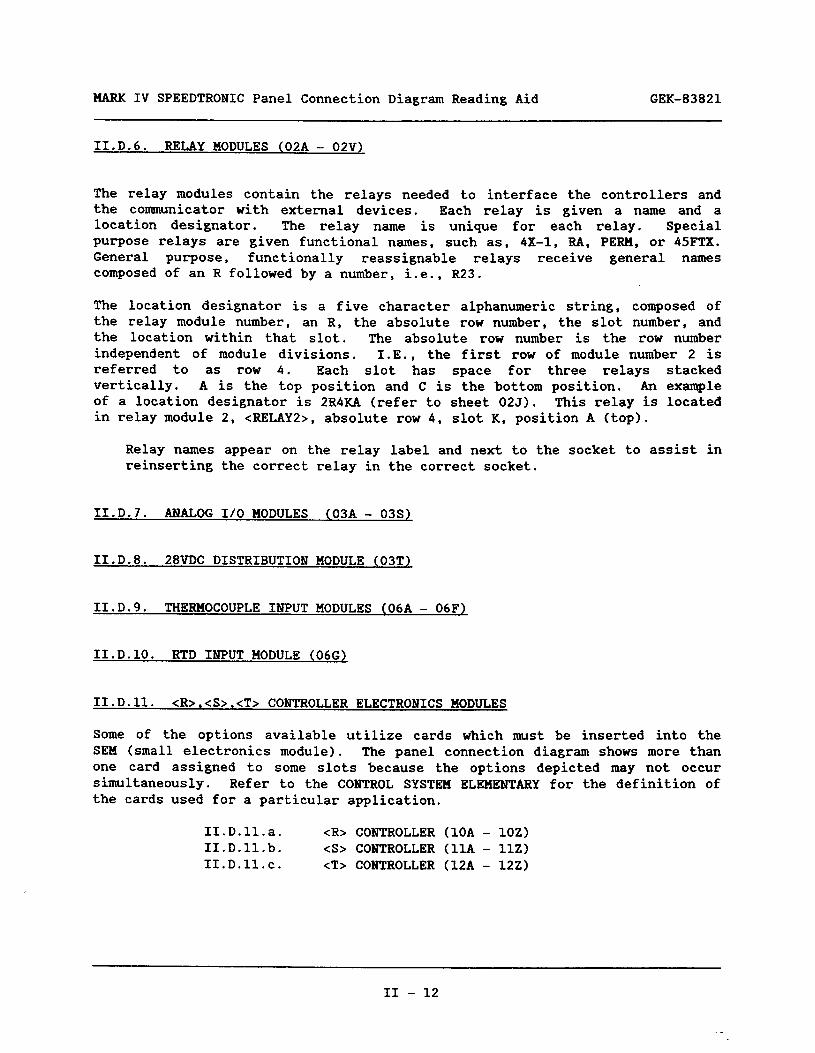
MARK IV SPEEDTRONIC Panel Connection Diagram Reading Aid GEK-83821
II.D.6. RELAY MODULES (02A - 02V)
The relay modules contain the relays needed to interface the controllers and the communicator with external devices. Each relay is given a name and a location designator. The relay name is unique for each relay. Special purpose relays are given functional names, such as, 4X-1, RA, PERM, or 45FTX. General purpose, functionally reassignable relays receive general names composed of an R followed by a number, i.e., R23.
The location designator is a five character alphanumeric string, composed of the relay module number, an R, the absolute row number, the slot number, and the location within that slot. The absolute row number is the row number independent of module divisions. I.E., the first row of module number 2 is referred to as row 4. Each slot has space for three relays stacked vertically. A is the top position and C is the bottom position. An example of a location designator is 2R4KA (refer to sheet 025). This relay is located in relay module 2, <RELAY2>, absolute row 4, slot K, position A (top).
Relay names appear on the relay label and next to the socket to assist in reinserting the correct relay in the correct socket.
II.D.7. ANALOG I/O MODULES (03A - 03s)
II.D.8. 28VDC DISTRIBUTION MODULE (03T)
II.D.9. THERMOCOUPLE INPUT MODULES (06A - 06F)
II.D.lO. RTD INPUT MODULE (066)
II.D.ll. cR>.<S>,<T> CONTROLLER ELECTRONICS MODULES
Some of the options available utilize cards which must be inserted into the SEM (small electronics module). The panel connection diagram shows more than one card assigned to some slots because the options depicted may not occur simultaneously. Refer to the CONTROL SYSTEM ELEMENTARY for the definition of the cards used for a particular application.
1I.D.ll.a. <R> CONTROLLER (10A - 1OZ) 1I.D.ll.b. <S> CONTROLLER (11A - 1lZ) 1I.D.ll.c. <T> CONTROLLER (12A - 122)
II - 12

GEK-83821 MARK IV SPEEDTRONIC Panel Connection Diagram Reading Aid
II.D.12. <C> COMMUNICATOR MODULE (13A - 142)
Some of the options available utilize a card which must be inserted into the MEM (medium electronics module). The panel connection diagram shows more than one card assigned to some slots because the options depicted may not occur simultaneously. Refer to the CONTROL SYSTEM ELEMENTARY for the definition of the cards used for a particular application.
II.D.13. <RDM> RELAY DRIVER MODULE (20A - 202)
II.D.14. <OPM> OPERATOR INTERFACE MODULE (21A - 21D)
II.D.15. <CRT> VIDEO DISPLAY (216)
II.D.16. <PTR> PRINTER (PANEL MOUNTED (21G)
II.D.17. <CLIMl-2> COMMUNICATION LINE ISOLATION MODULES (OPTION) (22A - 22B)
II.D.18. <SYNCH> SYNCHRONIZING INTERFACE MODULE (OPTION) (23A)
II.D.19. <FDl-4> FLAME DETECTORS (24A - 24D)
II.D.20. <INV> BLACK START INVERTER (28A)
II.D.21. <PDM> POWER DISTRIBUTION MODULE (29A - 29BA)
1I.E. CONCLUSION
This concludes the discussion of the panel connection diagram.
II - 13

MARK IV SPEEDTRONIC Panel Connection Diagram Reading Aid GEK-83821
USER NOTES
II - 14

GEK-83821 MARK IV SPEEDTROIIC Panel Connection Diagram Reading Aid
USER NOTES
II - 15

MARK IV SPEEDTRONIC Panel Connection Diagram Reading Aid GEK-83821
II - 16

GE Drive Systems
General Electric Company 1501 Roanoke Boukard Salem, Virginia 24 153 (703) 387-7000