82-01.54.019929-1.6 se-1 electrocardiograph user manual
TRANSCRIPT

EDAN Agile PLM Electronic Signature Information--Signatures related to this document and performed in EDAN Agile PLM.
文件名称(Document Name):SE-1说明书_英文文件编号(Number):01.54.019929版本(Version):1.6产品型号(Product Model):SE-1项目编码(Project Code):2080C000 签批信息(Signature): 作者(Originator) : 肖 丽军 (xiaolijun) 2016-10-20 15:31:58 审核人(Reviewers) : 董 宁 (dongning) 2016-10-20 15:53:43 审核人(Reviewers) : 肖 玉华 (xiaoyuhua) 2016-10-20 16:30:19 批准人(Approvers) : 王 力维 (wangliwei) 2016-10-24 10:36:04 批准人(Approvers) : 杨 洁 (yangjie) 2016-10-24 11:04:30 批准人(Approvers) : 陈 浩杰 (chenhaojie) 2016-10-24 09:21:25 版权©深圳市理邦精密仪器股份有限公司 (Copyright©Edan Instrument,Inc.)
理邦保密文件
EDAN CONFIDENTIAL


I
About this Manual
P/N: 01.54.019929
MPN: 01.54.019929016
Release Date: Oct. 2016
© Copyright EDAN INSTRUMENTS, INC. 2005-2016. All rights reserved.
Statement
This manual will help you understand the operation and maintenance of the product better. It is
reminded that the product shall be used strictly complying with this manual. User’s operation
failing to comply with this manual may result in malfunction or accident for which EDAN
INSTRUMENTS, INC. (hereinafter called EDAN) can not be held liable.
EDAN owns the copyrights of this manual. Without prior written consent of EDAN, any
materials contained in this manual shall not be photocopied, reproduced or translated into other
languages.
Materials protected by the copyright law, including but not limited to confidential information
such as technical information and patent information are contained in this manual, the user shall
not disclose such information to any irrelevant third party.
The user shall understand that nothing in this manual grants him, expressly or implicitly, any
right or license to use any of the intellectual properties of EDAN.
EDAN holds the rights to modify, update, and ultimately explain this manual.
Responsibility of the Manufacturer
EDAN only considers itself responsible for any effect on safety, reliability and performance of
the equipment if:
Assembly operations, extensions, re-adjustments, modifications or repairs are carried out by
persons authorized by EDAN, and
The electrical installation of the relevant room complies with national standards, and
The instrument is used in accordance with the instructions for use.

II
Terms Used in this Manual
This guide is designed to give key concepts on safety precautions.
WARNING
A WARNING label advises against certain actions or situations that could result in personal
injury or death.
CAUTION
A CAUTION label advises against actions or situations that could damage equipment, produce
inaccurate data, or invalidate a procedure.
NOTE
A NOTE provides useful information regarding a function or a procedure.

III
Table of Contents
Chapter 1 Safety Guidance ........................................................................................................... 1
1.1 Indications for Use/Intended Use ........................................................................................ 1
1.2 Warnings and Cautions ........................................................................................................ 1
1.2.1 Safety Warnings ........................................................................................................ 1
1.2.2 Lithium Battery Care Warnings ................................................................................ 5
1.2.3 General Cautions ....................................................................................................... 6
1.2.4 Cleaning & Disinfection Cautions ............................................................................ 7
1.3 List of Symbols ................................................................................................................... 7
Chapter 2 Introduction ................................................................................................................ 10
2.1 Top Panel ........................................................................................................................... 10
2.2 Key Panel and Keys .......................................................................................................... 11
2.3 Patient Cable Socket and Signal Interface ........................................................................ 14
2.4 Mains Connection and Switch .......................................................................................... 16
2.5 Bottom Panel ..................................................................................................................... 17
2.6 Function Features .............................................................................................................. 18
Chapter 3 About SE-1 Application Interface ............................................................................. 19
3.1 About the Main Interface .................................................................................................. 19
3.2 About the System Setup Interface ..................................................................................... 20
Chapter 4 Operation Preparations ............................................................................................. 21
4.1 Power and Earthling .......................................................................................................... 21
4.2 Loading/Replacing Recorder Paper .................................................................................. 22
4.3 Preparing the Patient ......................................................................................................... 23
4.3.1 Instructing the Patient ............................................................................................. 23
4.3.2 Preparing the Skin ................................................................................................... 23
4.4 Connecting the Patient Cable to the Electrocardiograph and Electrodes .......................... 24
4.5 Attaching Electrodes to the Patient ................................................................................... 25
4.6 Inspection Before Power-On ............................................................................................. 28
Chapter 5 Switching On the Electrocardiograph ...................................................................... 30
Chapter 6 Entering Patient Information ................................................................................... 31
Chapter 7 Printing ECG Reports ............................................................................................... 32
7.1 Auto Mode ......................................................................................................................... 32
7.2 Manual Mode .................................................................................................................... 33

IV
7.3 ECG Report ....................................................................................................................... 34
Chapter 8 Settings ........................................................................................................................ 35
8.1 Filter Settings .................................................................................................................... 36
8.2 Recording Settings ............................................................................................................ 36
8.3 Date and Time Settings ..................................................................................................... 37
8.4 Print Head Test .................................................................................................................. 37
8.5 External Input/Output Settings .......................................................................................... 38
8.6 Key Beep and QRS Beep Settings .................................................................................... 38
8.7 Rhythm Lead Settings ....................................................................................................... 38
Chapter 9 Switching Off the Electrocardiograph ..................................................................... 39
Chapter 10 Hint Information ...................................................................................................... 40
Chapter 11 Cleaning, Care and Maintenance ........................................................................... 41
11.1 General Points ................................................................................................................. 41
11.2 Cleaning .......................................................................................................................... 41
11.2.1 Cleaning the Main Unit ......................................................................................... 42
11.2.2 Cleaning the Patient Cable .................................................................................... 42
11.2.3 Cleaning the Reusable Electrodes ......................................................................... 42
11.3 Disinfection ..................................................................................................................... 43
11.3.1 Disinfecting the Main Unit .................................................................................... 43
11.3.2 Disinfecting the Patient Cable ............................................................................... 44
11.3.3 Disinfecting the Reusable Electrodes .................................................................... 44
11.4 Care and Maintenance ..................................................................................................... 44
11.4.1 Recharge and Replacement of Battery .................................................................. 44
11.4.2 Recorder Paper ...................................................................................................... 45
11.4.3 Maintenance of Main Unit, Patient Cable and Electrodes .................................... 46
Chapter 12 Accessories and Ordering Information .................................................................. 49
Chapter 13 Warranty and Service .............................................................................................. 51
13.1 Warranty .......................................................................................................................... 51
13.2 Contact information ........................................................................................................ 51
Appendix 1 Technical Specifications .......................................................................................... 52
A1.1 Safety Specifications ...................................................................................................... 52
A1.2 Environment Specifications ........................................................................................... 53
A1.3 Physical Specifications ................................................................................................... 53
A1.4 Power Supply Specifications .......................................................................................... 53
A1.5 Performance Specifications ............................................................................................ 54

V
Appendix 2 EMC Information .................................................................................................... 56
Appendix 3 Abbreviation ............................................................................................................. 60

SE-1 Electrocardiograph User Manual Safety Guidance
- 1 -
Chapter 1 Safety Guidance This chapter provides important safety information related to the use of the single channel electrocardiograph.
1.1 Indications for Use/Intended Use
The intended use of the single channel electrocardiograph is to acquire ECG signals from adult and pediatric patients through body surface ECG electrodes. The electrocardiograph is intended to be used only in hospitals or healthcare facilities by doctors and trained healthcare professionals. The cardiogram recorded by the single channel electrocardiograph can help users to analyze and diagnose heart disease. However the ECG is offered to clinicians on an advisory basis only.
1.2 Warnings and Cautions
In order to use the electrocardiograph safely and effectively, and avoid possible dangers caused by improper operation, please read through the user manual and be sure to be familiar with all functions of the equipment and proper operation procedures before use.
Please pay more attention to the following warning and caution information.
Note:
1. This device is not intended for home use.
2. The pictures and interfaces in this manual are for reference only.
1.2.1 Safety Warnings
WARNING
1. The electrocardiograph is intended to be used by qualified physicians or personnel professionally trained. They should be familiar with the contents of this user manual before operation.
2. Only qualified service engineers can install this equipment, and only service engineers authorized by the manufacturer can open the shell. Otherwise, safety hazards may happen.
3. Only qualified installation or service engineers can shift the mains supply shift switch (100V-115V~/220V-240V~) according to local mains supply specifications.

SE-1 Electrocardiograph User Manual Safety Guidance
- 2 -
WARNING
4. The results given by the equipment should be examined based on the overall clinical condition of the patient, and they can not substitute for regular checking.
5. This device is not intended for treatment.
6. EXPLOSION HAZARD - Do not use the electrocardiograph in the presence of flammable anesthetic mixtures with oxygen or other flammable agents.
7. SHOCK HAZARD - The power receptacle must be a hospital grade grounded outlet. Never try to adapt the three-prong plug to fit a two-slot outlet.
8. If the integrity of the external protective conductor is in doubt, the equipment should be powered by a built-in rechargeable battery.
9. Do not use this equipment in the presence of high static electricity or high voltage equipment which may generate sparks.
10. This equipment is not designed for direct cardiac application.
11. Only the patient cable and other accessories supplied by the manufacturer can be used. Or else, the performance and electric shock protection cannot be guaranteed.
12. The use of patient cable and other accessories not supplied by the manufacturer may result in increased emissions or decreased immunity of the equipment.
13. Make sure that all electrodes are connected to the patient correctly before operation.
14. Ensure that the conductive parts of electrodes and associated connectors, including neutral electrodes, do not come in contact with earth or any other conducting objects.
15. Electrodes with defibrillator protection should be used while defibrillating. To avoid a polarization or DC offset voltage, use non-polarizing electrodes (which will not form a DC offset voltage when subjected to a DC current) such as silver/silver-chloride types if there is a situation where there is a likelihood that a defibrillation procedure will be necessary.
16. There is no danger for patients to use pacemakers. However, if a pacemaker is used, the results given by the equipment may be invalid, or lose the clinical significance.
17. Do not touch the patient, bed, table or the equipment while using the ECG together with a defibrillator.
18. Do not touch accessible parts of electrical equipment and the patient simultaneously.
19. In order to avoid being burnt, please keep the electrodes far away from the radio knife while using electrosurgical equipment.

SE-1 Electrocardiograph User Manual Safety Guidance
- 3 -
WARNING
20. Disposable electrodes must be used during defibrillation
21. Accessory equipment connected to the analog and digital interfaces must be certified according to the respective IEC/EN standards (e.g. IEC/EN 60950 for data processing equipment and IEC/EN 60601-1 for medical equipment). Furthermore all configuration shall comply with the valid version of the standard IEC/EN 60601-1-1. Therefore anybody, who connects additional equipment to the signal input or output connector to configure a medical system, must make sure that it complies with the requirements of the valid version of the system standard IEC/EN 60601-1-1. If in doubt, consult our technical service department or your local distributor.
22. Connecting any accessory (such as external printer) or other device (such as the computer) to this electrocardiograph makes a medical system. In that case, additional safety measures should be taken during installation of the system, and the system shall provide:
a) Within the patient environment, a level of safety comparable to that provided by
medical electrical equipment complying with IEC/EN 60601-1, and
b) Outside the patient environment, the level of safety appropriate for non-medical electrical equipment complying with other IEC or ISO safety standards.
23. All the accessories connected to system must be installed outside the patient vicinity, if they do not meet the requirement of IEC/EN 60601-1.
24. SHOCK HAZARD - Don't connect non-medical electrical equipment, which has been supplied as a part of the system, directly to the wall outlet when the non-medical equipment is intended to be supplied by a multiple portable socket-outlet with an isolation transformer.
25. SHOCK HAZARD - Don't connect electrical equipment, which has not been supplied as a part of the system, to the multiple portable socket-outlet supplying the system.
26. Do not connect any equipment or accessories that are not approved by the manufacturer or that are not IEC/EN 60601-1 approved to the electrocardiograph. The operation or use of non-approved equipment or accessories with the electrocardiograph is not tested or supported, and electrocardiograph operation and safety are not guaranteed.

SE-1 Electrocardiograph User Manual Safety Guidance
- 4 -
WARNING
27. Do not use the additional multiple portable socket-outlet or extension cord in the medical electrical system, unless it's specified as part of the system by manufacturer. And the multiple portable socket-outlets provided with the system shall only be used for supplying power to equipment which is intended to form part of the system.
28. The summation of leakage current should never exceed leakage current limits while several other units are used at the same time.
29. The potential equalization conductor can be connected to that of other equipment when necessary, to make sure that all these devices are connected to the potential equalization bus bar of the electrical installation.
30. The EQUIPMENT is protected against malfunctions caused by electrosurgery according to the clause 36.202.101 in the standard IEC 60601-2-25.
31. The electrocardiograph shall not be serviced or maintained while in use with a patient.
32. The appliance coupler or mains plug is used as isolation means from supply mains. Position the electrocardiograph in a location where the operator can easily access the disconnection device.
33. The medical electrical equipment needs to be installed and put into service according to Appendix 2 EMC information.
34. The equipment should not be used adjacent to or stacked with other equipment, refer to the recommended separation distances provided in Appendix 2 EMC Information.
35. Portable and mobile RF communications equipment can affect medical electrical equipment, refer to the recommended separation distances provided in Appendix 2 EMC Information.
36. Assembly of the electrocardiograph and modifications during actual service life shall be evaluated based on the requirements of IEC60601-1.

SE-1 Electrocardiograph User Manual Safety Guidance
- 5 -
1.2.2 Lithium Battery Care Warnings
WARNING
1. Improper operation may cause the lithium battery (hereinafter called battery) to be hot, ignited or exploded, and it may lead to the decrease of the battery capacity. It is necessary to read the user manual carefully and pay more attention to warning messages.
2. Only qualified service engineers authorized by the manufacturer can open the battery compartment and replace the battery, and batteries of the same model and specification should be used.
3. Danger of explosion -- Do not reverse the anode and the cathode when installing the battery.
4. Do not heat or splash the battery or throw it into fire or water.
5. When leakage or foul smell is found, stop using the battery immediately. If your skin or cloth comes into contact with the leakage liquid, cleanse it with clean water at once. If the leakage liquid splashes into your eyes, do not wipe them. Irrigate them with clean water first and go to see a doctor immediately.
6. The device and accessories are to be disposed of according to local regulations after their useful lives. Alternatively, they can be returned to the dealer or the manufacturer for recycling or proper disposal. Batteries are hazardous waste. Do NOT dispose of them together with house-hold garbage. At the end of their lives hand the batteries over to the applicable collection points for the recycling of waste batteries. For more detailed information about recycling of this product or the battery, please contact your local Civic Office, or the shop where you purchased the product.
7. Only when the device is off can the battery be installed or removed.
8. Remove the battery from the electrocardiograph when the electrocardiograph is not used for a long time.
9. If the battery is stored alone and not used for a long time, we recommend that the battery should be charged at least once every 6 months to prevent overdischarge.

SE-1 Electrocardiograph User Manual Safety Guidance
- 6 -
1.2.3 General Cautions
CAUTION
1. Avoid liquid splash and excessive temperature. The temperature must be kept between 5 ºC and 40 ºC during operation, and it should be kept between -20 ºC and 55 ºC during transportation and storage.
2. Do not use the equipment in a dusty environment with bad ventilation or in the presence of corrosive.
3. Make sure that there is no intense electromagnetic interference source around the equipment, such as radio transmitters or mobile phones etc. Attention: large medical electrical equipment such as electrosurgical equipment, radiological equipment and magnetic resonance imaging equipment etc. is likely to bring electromagnetic interference.
4. Before use, the equipment, patient cable and electrodes etc. should be checked. Replacement should be taken if there is any evident defectiveness or aging symptom which may impair the safety or the performance.
5. The following safety checks should be performed at least every 24 months by a qualified person who has adequate training, knowledge, and practical experience to perform these tests.
a) Inspect the equipment and accessories for mechanical and functional damage.
b) Inspect the safety relevant labels for legibility.
c) Inspect the fuse to verify compliance with the rated current and circuit-breaking characteristics.
d) Verify that the device functions properly as described in the instructions for use.
e) Test the protection earth resistance according to IEC/EN 60601-1: Limit 0.1 ohm.
f) Test the earth leakage current according to IEC/EN 60601-1: Limit: NC 500μA, SFC 1000μA.
g) Test the enclosure leakage current according to IEC/EN 60601-1: Limit: NC 100μA, SFC 500μA.
h) Test the patient leakage current according to IEC/EN 60601-1: Limit: NC a.c. 10μA, d.c. 10μA; SFC a.c. 50μA, d.c. 50μA.
i) Test the patient auxiliary current according to IEC/EN 60601-1: Limit: NC a.c. 10μA, d.c. 10μA; SFC a.c. 50μA, d.c. 50μA.

SE-1 Electrocardiograph User Manual Safety Guidance
- 7 -
CAUTION
j) Test the patient leakage current under single fault condition with mains voltage on the applied part according to IEC/EN 60601-1: Limit: 50μA (CF)
The data should be recorded in an equipment log. If the device is not functioning properly or fails any of the above tests, the device has to be repaired.
6. Ruptured fuse must only be replaced with that of the same type and rating as the original.
1.2.4 Cleaning & Disinfection Cautions
CAUTION
1. Turn off the power before cleaning and disinfection. If the mains supply is used, the power cord should be dragged out of the outlet. Prevent the detergent from seeping into the equipment.
2. Do not immerse the unit or the patient cable into liquid under any circumstances.
3. Do not clean the unit and accessories with abrasive fabric and avoid scratching the electrodes.
4. Any remainder of detergent should be removed from the unit and the patient cable after cleaning.
5. Do not use chloric disinfectant such as chloride, sodium hypochlorite etc.
1.3 List of Symbols
No. Symbol Description
1 Output
2 Input

SE-1 Electrocardiograph User Manual Safety Guidance
- 8 -
3
DEFIBRILLATION-PROOF TYPE CF APPLIED PART
4
Attention, consult ACCOMPANYING DOCUMENTS
5
Operating instructions
6
Equipotential grounding
7 Alternating Current
8
"ON" (power)
9
"OFF" (power)
10 Battery check
11 Battery recharging indicator
12
General symbol for recovery/recyclable
13 Part Number
14 SERIAL NUMBER
15
Date of manufacture

SE-1 Electrocardiograph User Manual Safety Guidance
- 9 -
16
MANUFACTURER
17
AUTHORISED REPRESENTATIVE IN THE EUROPEAN COMMUNITY
18 CE marking
19
Disposal method
20
Refer to User Manual
(Background: Blue; Symbol: White)
21
Warning
(Background: Yellow; Symbol&Outline: Black)
22
Caution: Federal (U.S.) law restricts this device to sale by or on the order of a physician.
NOTE: The user manual is printed in black and white.

SE-1 Electrocardiograph User Manual Introduction
- 10 -
Chapter 2 Introduction SE-1 electrocardiograph is a high-performance single channel digital electrocardiograph.
1-channel ECG wave and the real-time heart rate can be viewed on the LCD screen, and printed out by using a high resolution thermal recorder. The auto and manual modes can be chosen freely. SE-1 can be powered by the mains supply or a built-in rechargeable lithium battery.
Configuration: main unit and accessories, including patient cable, chest electrodes, limb electrodes, thermal recorder paper, power cord etc.
WARNING
1. This equipment is intended for use on adult and pediatric patients only.
2. This equipment is not designed for direct cardiac application.
3. The results given by the equipment should be examined based on the overall clinical condition of the patient, and they can not substitute for regular checking.
2.1 Top Panel
Figure 2-1 Main Unit
LCD Screen
Patient Cable Socket
Recorder Paper
RS232 Socket (Rese
Recorder
Key Panel
External Input/Output Socket
USB Interface (Reserved)

SE-1 Electrocardiograph User Manual Introduction
- 11 -
2.2 Key Panel and Keys
1) Indicator
Mains supply indicator: when the device is powered by the mains supply, the indicator will be lit.
Battery indicator: when the device is powered by a built-in rechargeable lithium battery, the indicator will be lit.
Battery recharging indicator: after you connect the power cord to the outlet and press the mains switch, both the battery recharging indicator and the mains supply indicator will be lit.
Note: When the device is powered off, the recharging indicator is still lit after t
he battery is fully charged.
2) SENS (Sensitivity Switch Key)
The sensitivity switch order: ×1 → ×2 → AGC → · 25 → · 5. The measurable and recordable ECG signal range varies with the sensitivity, as the following list shows.
Option Sensitivity Signal Range
×1 10mm/mV -2.5mV ~ +2.5mV
×2 20mm/mV -1.25mV ~ +1.25mV
AGC Adjust sensitivity automatically Vary with the adjusted sensitivity

SE-1 Electrocardiograph User Manual Introduction
- 12 -
· 25 2.5mm/mV -10mV ~ +10mV
· 5 5mm/mV -5mV ~ +5mV
If the fluctuating range of the ECG signal is great, it’s better to choose AGC because the sensitivity can be adjusted automatically in this mode.
Note: This key is ineffective during the printing course in the auto mode.
3) RESET (Lead Locking Key)
In the manual mode, during the printing course, pressing this key can lock the lead, and then the corresponding ECG wave shows a straight line. The lead will be unlocked automatically after 1 second. So in the case of baseline drift, press this key to draw the baseline to zero quickly, and the ECG wave resumes after 1 second.
4) 1mV Calibration Key
In the manual mode, press this key to print a 1mV calibration mark during the printing course.
5) MODE (Mode Switch Key)
Press this key to select a working mode among four auto modes and a manual mode. The switch order of leads in each mode is listed in Table 2-1.
Table 2-1 Lead Switch Order in Different Modes
Mode Switch Order (from Left to Right)
MANU І II III aVR aVL aVF V1 V2 V3 V4 V5 V6
AUTO1 І II III aVR aVL aVF V1 V2 V3 V4 V5 V6
AUTO2 aVL І aVR II aVF III V1 V2 V3 V4 V5 V6
AUTO3 І aVR V1 V4 II aVL V2 V5 III aVF V3 V6
AUTO4 2-channel auto mode (AUTO1 + Rhythm Lead)

SE-1 Electrocardiograph User Manual Introduction
- 13 -
6) LEAD (Lead Switch Key)
In the manual mode, press this key to switch the leads in order.
7) PRINT/STOP Key
Press this key to begin or stop printing ECG reports.
8) ON/OFF Key
After you connect the power cord to the outlet and press the mains switch, press this key to turn on or off the device.
9) MENU Key
Press this key to open the system setup interface.
10) ID Setting Key
Press these two keys to set the patient ID. Press the up arrow key to increase the ID number and press the down arrow key to decrease the ID number.
11) M/F
Press the M/F key to set the sex of the patient to Male or Female.

SE-1 Electrocardiograph User Manual Introduction
- 14 -
12) AGE
Press the AGE key to set the patient’s age group to CHILD, ADULT or OLD.
2.3 Patient Cable Socket and Signal Interface As Figure 2-1 shows, on the right side of the main unit are the patient cable socket, RS232 socket (reserved), external input/output socket and USB interface (reserved).
1) Patient Cable Socket
: DEFIBRILLATION-PROOF TYPE CF APPLIED PART
: Attention, consult ACCOMPANYING DOCUMENTS
Definitions of corresponding pins:
Pin Signal Pin Signal Pin Signal
1 C2 / V2 6 SH 11 F / LL
2 C3 / V3 7 NC 12 C1 / V1
or NC
3 C4 / V4 8 NC 13 C1 / V1
4 C5 / V5 9 R / RA 14 RF (N) /RL
or NC
5 C6 / V6 10 L / LA 15 RF (N) / RL
Note: The left side of “/” is European standard; and the right side is American standard.

SE-1 Electrocardiograph User Manual Introduction
- 15 -
2) RS232 Socket (Reserved)
Definitions of corresponding pins:
Pin Signal Pin Signal Pin Signal
1 NC 4 NC 7 NC
2 RxD (input) 5 GND 8 NC
3 TxD (output) 6 NC 9 NC
3) External Input/Output Socket
Definitions of corresponding pins:
Pin Signal Pin Signal
1 GND 4 GND
2 GND 5 ECG Signal (input)
3 GND 6 ECG Signal (output)
4) USB Interface (Reserved)
WARNING
1. Accessory equipment connected to the analog and digital interfaces must be certified
according to the respective IEC/EN standards (e.g. IEC/EN 60950 for data processing
equipment and IEC/EN 60601-1 for medical equipment). Furthermore all configuration
shall comply with the valid version of the standard IEC/EN 60601-1-1. Therefore
anybody, who connects additional equipment to the signal input or output connector to
configure a medical system, must make sure that it complies with the requirements of

SE-1 Electrocardiograph User Manual Introduction
- 16 -
WARNING
the valid version of the system standard IEC/EN 60601-1-1. If in doubt, consult our technical service department or your local distributor.
2. The summation of leakage current should never exceed leakage current limits while several other units are used at the same time.
2.4 Mains Connection and Switch
As the above figure shows, on the left side of the main unit are the mains socket, mains switch and potential equalization conductor.
1) Potential Equalization Conductor
The potential equalization conductor provides a connection between the unit and the potential equalization bus bar of the electrical installation.
2) Mains Socket
AC SOURCE: alternating current supply socket
3) Mains Switch
: On
: Off
Mains Switch Potential Equalization Conductor
Mains Socket

SE-1 Electrocardiograph User Manual Introduction
- 17 -
2.5 Bottom Panel
1) Battery Compartment
The battery label indicates the rated voltage and the rated capacity of the rechargeable lithium battery. Rated voltage: 14.8V, Rated capacity: 2500mAh.
: Attention, consult ACCOMPANYING DOCUMENTS
WARNING
Only qualified service engineers authorized by the manufacturer can open the battery compartment and replace the battery. The battery of the same model and specification provided by the manufacturer must be used.
2) Mains Supply Shift Switch
The mains supply with the rated input voltage of 230V (220V-240V~) or 115V (100V-115V~) can be chosen by using the shift switch according to local mains supply specifications.
WARNING
Only qualified installation or service engineers can shift the mains supply shift switch according to local mains supply specifications.
Mains Supply Shift Switch
Fuse Label
Battery Compartment
Label
Fuse

SE-1 Electrocardiograph User Manual Introduction
- 18 -
3) Fuse
There are two fuses of the same specifications installed on the bottom of the main unit. The specifications are shown on the fuse label: T400mAH250V, Ø5×20mm.
WARNING
Ruptured fuses must only be replaced with those of the same type and rating as the original.
2.6 Function Features
♦ Low weight and compact size
♦ Well designed membrane key panel for easy operation
♦ LCD screen for single channel ECG view
♦ Four auto modes and a manual mode are optional
♦ General menu for setting parameters
♦ Built-in rechargeable lithium battery with large capacity
♦ Hint information of lead off, lack of paper, low battery capacity etc.
♦ Thermal dot-matrix recorder for high-resolution printout
♦ Automatic adjustment of baseline for optimal printing
♦ Selectable printing formats, standard single channel or single channel & rhythm lead
♦ Standard external input/output interface

SE-1 Electrocardiograph User Manual About SE-1 Application Interface
- 19 -
Chapter 3 About SE-1 Application Interface The following sections provide an overview of the main functions in the SE-1 application. After
you turn on the device, the main interface pops up. Then you can press the MENU key to open
the system setup interface.
3.1 About the Main Interface
Figure 3-1 Main Interface
The LCD screen can be revolved and settled freely at different angles.
Normally, the contents displayed on the LCD screen include: (described from left to right in row order)
First Row:
♦ Working mode (AUTO1, AUTO2, AUTO3, AUTO4 and MANU)
♦ II stop symbol, which will turn to during the printing course
♦ Hint information (LDOFF, PAPER?, etc.)
♦ Current time
Second Row:
♦ Current lead (І, П, Ш, aVR, aVL, aVF, V1, V2, V3, V4, V5, V6)
♦ Heart rate (--, actual heart rate, or OVR)
Third Row:
♦ Filter setting (FLT = AC, EMG, ALL, OFF)
♦ ECG wave

SE-1 Electrocardiograph User Manual About SE-1 Application Interface
- 20 -
Fourth Row:
♦ Sensitivity (×1, ×2, AGC, · 25, · 5)
♦ Paper speed (25, 50)
♦ Battery capacity symbol ( , , , )
♦ When you are setting the ID, sex or age group, the item will be shown here. The hint BATTERY WEAK will be shown here when the battery capacity is low.
3.2 About the System Setup Interface
When the main interface is displayed, press the MENU key to open the system setup interface. Press the MENU key again to return to the main interface.
Figure 3-2 System Setup Interface
1. Press the ID key (the up or down arrow) to move the arrow
on the right of the LCD screen to the item to be changed.
2. Then press the M/F or AGE key to select an option for the item.
3. After setting the items, press the MENU key to exit the system setup interface.
: ALL
: ON
: 3
: SECOND
FILTER SETTING
PWAVE START
RECORD LENGTH
RECORD COUNT

SE-1 Electrocardiograph User Manual Operation Preparations
- 21 -
Chapter 4 Operation Preparations
CAUTION
Before use, the equipment, patient cable and electrodes should be checked. Replace them if there is any evident defectiveness or aging which may impair the safety or the performance. Make sure that the equipment is in proper working condition.
4.1 Power and Earthling
WARNING
If the integrity of the external protective conductor is in doubt, the equipment should be powered by the built-in rechargeable lithium battery.
Power Supply
The electrocardiograph can be powered either by the mains supply or a built-in rechargeable lithium battery.
1) Mains Supply
The mains socket is on the left side of the unit. If the mains supply is used, connect the power cord to the socket first, and then connect the power cord to the hospital grade outlet.
Operating voltage: 100V-115V~ / 220V-240V~
Operating frequency: 50Hz / 60Hz
Input power: 35VA
Make sure that the mains supply meets the above requirements before power-on, and then press the mains switch. Then the mains supply indicator ( ) will be lit as well as the battery recharging indicator ( ).
2) Built-in Rechargeable Battery
When the built-in rechargeable lithium battery is used, turn on the unit by pressing the ON/OFF key on the key panel directly. Then the battery indicator ( ) will be lit and the battery symbol will be displayed on the LCD screen. Because of the consumption during the storage and transport course, the battery capacity may not be full. If the symbol and the hint BATTERY WEAK are displayed, which means the battery capacity is low, please recharge the battery first.

SE-1 Electrocardiograph User Manual Operation Preparations
- 22 -
Please refer to the maintenance section for how to recharge the battery. When the battery is being recharged, SE-1 can be powered by the mains supply at the same time.
WARNING
The potential equalization conductor of the unit should be connected to the potential equalization bus bar of the electrical installation when necessary.
4.2 Loading/Replacing Recorder Paper
The rolled thermal paper with the width of 50mm is used. When the recorder paper runs out or is not loaded, the hint PAPER? will appear on the screen. Then you should load or replace the recorder paper immediately.
Loading/Replacing Process:
1) Place fingers under the two flanges of the recorder casing, pull them upwards directly to release the casing;
2) Take out the paper roller, and remove remainder paper from the roller if necessary;
3) Take off the wrapper of the new thermal paper roll, and then put the paper roll through the roller;
Paper Roller
Groove
Rol
Casing
Printer Platen
Paper Tray
Scale Thermal Print Head

SE-1 Electrocardiograph User Manual Operation Preparations
- 23 -
4) Place the paper and the roller gently in the recorder with the roller pin clicking into the groove;
5) Pull about 2cm of paper out with the grid side of the paper facing the thermal print head, and shut the recorder casing with the paper edges in parallel with the scales on the surface of the casing;
6) Press down the recorder casing firmly.
4.3 Preparing the Patient
4.3.1 Instructing the Patient
Before attaching the electrodes, greet the patient and explain the procedure. Explaining the
procedure decreases the patient’s anxiety. Reassure the patient that the procedure is painless.
Privacy is important for relaxation. When possible, prepare the patient in a quiet room or area
where others can’t see the patient. Make sure that the patient is comfortable. The more relaxed
the patient is, the less the ECG will be affected by noise.
4.3.2 Preparing the Skin
Thorough skin preparation is very important. The skin is a poor conductor of electricity and
frequently creates artifact that distorts the ECG signals. By performing methodical skin
preparation, you can greatly reduce the possibility of the noise caused by muscle tremor and
baseline drift, ensuring high-quality ECG waves. There is natural resistance on the skin surface
due to dry, dead epidermal cells, oils and dirt.
To Prepare the Skin
1. Shave hair from electrode sites, if necessary. Excessive hair prevents a good connection.
2. Wash the area thoroughly with soap and water.
3. Dry the skin with a gauze pad to increase capillary blood flow to the tissues and to remove the dead, dry skin cells and oils.

SE-1 Electrocardiograph User Manual Operation Preparations
- 24 -
4.4 Connecting the Patient Cable to the
Electrocardiograph and Electrodes
WARNING
The performance and electric shock protection can be guaranteed only if the original
patient cable and electrodes of the manufacturer are used.
The patient cable includes the main cable and the lead wires which can be connected to electrodes according to the colors and the identifiers.
1. Connecting the Patient Cable to the Electrocardiograph
Connect the patient cable to the patient cable socket on the right side of the main unit, and then
secure them with two screws.
2. Connecting the Patient Cable to Electrodes
Align all lead wires of the patient cable to avoid twisting, and connect the lead wires to the
electrodes. Firmly attach them.
WARNING
This product is CF classified and defibrillation protected only when the original patient cable is used. However, remove electrodes before defibrillation when possible as a safety precaution.
Connecting to Electrocardiograph
Screw
Main Cable
Connecting to Electrodes
Lead Wires

SE-1 Electrocardiograph User Manual Operation Preparations
- 25 -
4.5 Attaching Electrodes to the Patient
Chest Electrode:
Limb Electrode:
The identifiers and color codes of electrodes used comply with IEC/EN requirements. In order to avoid incorrect connections, the electrode identifiers and color codes are specified in Table 4-1. Moreover the equivalent codes according to American requirements are given in Table 4-1 too.
Table 4-1 Electrodes, Identifiers and Color Codes
European American
Electrodes Identifiers Color Codes Identifiers Color Codes
Right arm R Red RA White
Left arm L Yellow LA Black
Right leg N or RF Black RL Green
Left leg F Green LL Red
Chest 1 C1 White/red V1 Brown/red
Chest 2 C2 White/yellow V2 Brown/yellow
Chest 3 C3 White/green V3 Brown/green
Chest 4 C4 White/brown V4 Brown/ blue
Chest 5 C5 White/black V5 Brown/orange
Chest 6 C6 White/violet V6 Brown/violet
Reed
Connecting to Lead Wire
Clamp
Suction Bulb
Connecting to Lead Wire Metal Cup

SE-1 Electrocardiograph User Manual Operation Preparations
- 26 -
As the following figure shows, the positions of chest electrodes on the body surface are
C1: Fourth intercostal space at the right border of the sternum
C2: Fourth intercostal space at the left border of the sternum
C3: Fifth rib between C2 and C4
C4: Fifth intercostal space on the left midclavicular line
C5: Left anterior axillary line at the horizontal level of C4
C6: Left midaxillary line at the horizontal level of C4
The quality of ECG waveform will be affected by the contact resistance between the patient and the electrode. In order to get a high-quality ECG, the skin-electrode resistance must be minimized when you attach electrodes to patients.
Chest Electrode Connection:
1) Ensure that the electrodes are clean;
2) Align all lead wires of the patient cable to avoid twisting, and connect the lead wires to the corresponding electrodes according to the colors and the identifiers;
3) Clean the electrode area on the chest surface with alcohol;
4) Daub the round area of 25mm in diameter on each electrode site with gel evenly;
5) Place a small amount of gel on the brim of the chest electrode’s metal cup;
6) Place the electrode on the chest electrode site and squeeze the suction bulb. Unclench it and the electrode is adsorbed on the chest;
7) Attach all chest electrodes in the same way.
C6
C1
C2
C5
C4
C3

SE-1 Electrocardiograph User Manual Operation Preparations
- 27 -
Limb Electrode Connection:
1) Ensure that the electrodes are clean;
2) Align all lead wires of the patient cable to avoid twisting, and connect the lead wires to the corresponding electrodes according to the colors and the identifiers;
3) Clean the electrode area which is a short distance above the ankle or the wrist with alcohol;
4) Daub the electrode area on the limb with gel evenly;
5) Place a small amount of gel on the metal part of the limb electrode clamp;
6) Connect the electrode to the limb, and make sure that the metal part is placed on the electrode area above the ankle or the wrist;
7) Attach all limb electrodes in the same way.
WARNING
1. Make sure that all electrodes are connected to the patient correctly before operation. 2. Make sure that the conductive parts of electrodes and associated connectors,
including neutral electrodes, do not come in contact with earth or any other conducting objects.
3. Electrodes with defibrillator protection should be used while defibrillating. To avoid a polarization or DC offset voltage, use non-polarizing electrodes (which will not form a
DC offset voltage when subjected to a DC current) such as silver/silver-chloride types if there is a situation where there is a likelihood that a defibrillation procedure will be necessary.
4. Do not touch the patient, bed, table or the equipment while using the ECG together with a defibrillator.

SE-1 Electrocardiograph User Manual Operation Preparations
- 28 -
4.6 Inspection Before Power-On
In order to avoid safety hazards and get good ECG records, the following inspection procedure
is recommended before power-on and operation.
1) Environment:
♦ Make sure that there is no electromagnetic interference source around the equipment, especially large medical electrical equipment such as electrosurgical equipment, radiological equipment, magnetic resonance imaging equipment etc. Switch off these devices when necessary.
♦ Keep the examination room warm to avoid muscle tremor caused by cold.
2) Power Supply:
♦ If the mains supply is used, please check whether the power cord is connected to the unit well. The grounded three-slot outlet should be used.
♦ When the battery capacity is low, recharge the battery before use.
3) Patient Cable:
♦ Make sure that the patient cable is connected to the unit firmly, and keep it far away from the power cord.
4) Electrodes:
♦ Make sure that all electrodes are connected to lead wires of the patient cable correctly.
♦ Make sure that all electrodes are connected to the patient correctly.
♦ Ensure that the chest electrodes do not contact.
5) Recorder Paper:
♦ Ensure that there is enough recorder paper loaded correctly.
♦ Make sure that the recorder casing is secured.
6) Patient:
♦ The patient should not come into contact with conducting objects such as earth, metal parts etc.
♦ Ensure that the patient is warm and relaxed, and breathes calmly.

SE-1 Electrocardiograph User Manual Operation Preparations
- 29 -
WARNING
The electrocardiograph is intended to be used by qualified physicians or personnel
professionally trained, and they should be familiar with the contents of this user manual
before operation.

SE-1 Electrocardiograph User Manual Switching On the Electrocardiograph
- 30 -
Chapter 5 Switching On the Electrocardiograph
♦ When the mains supply is used, connect the power cord, press the mains switch on the left side of the unit, and then the mains supply indicator ( ) is lit. Then press the ON/OFF key on the key panel to turn on the unit. The equipment information such as the device name, the version number will be displayed on the LCD screen after self-test. Then SE-1 is ready for use.
♦ When a built-in rechargeable lithium battery is used, press the ON/OFF key on the key panel directly to turn on the unit, and then the battery indicator ( ) is lit. The equipment information such as the device name, the version number will be displayed on the LCD screen after self-test. Then SE-1 is ready for use.

SE-1 Electrocardiograph User Manual Entering Patient Information
- 31 -
Chapter 6 Entering Patient Information
1. Entering ID Number
Press the ID key (the up or down arrow) to set the patient’s ID.
Press the up arrow key to increase the ID number and press the down arrow key to decrease the ID number.
After set, the ID number will be displayed for one or two seconds in the last row on the LCD screen, such as ECG 256 in the above figure.
In the auto or manual mode, if you press PRINT/STOP to print a new report, the ID number will increase by one automatically.
2. Entering the Patient’s Sex
Press the M/F key to set the sex of the patient, which will be displayed for one or two seconds in the last row on the LCD screen, such as MALE in the above figure.
3. Entering the Patient’s Age Group
Patients are divided into three age groups: CHILD, ADULT, OLD. Press the AGE key to set the age group, which will be displayed for one or two seconds in the last row on the LCD screen, such as ADULT in the above figure.
Note: The patient information mentioned above can not be set or changed during the printing course.
AUTO 1 II
І NO
FLT = ALL
×1 25 E C G 2 5 6 MALE ADULT
10 : 50

SE-1 Electrocardiograph User Manual Printing ECG Reports
- 32 -
Chapter 7 Printing ECG Reports
There are four auto modes: AUTO 1, AUTO 2, AUTO 3 and AUTO 4. Two channels, including a rhythm lead, can be printed together in the AUTO 4 mode. The lead switch orders in different modes are listed in Table 2-1.
In the auto mode, leads will be switched in order automatically during the printing course. After the ECG wave of one lead is printed for the set time period, the device will switch to print the ECG wave of next lead automatically. There is a blank area on the recorder paper before printing the ECG wave of next lead in the AUTO1, AUTO2 and AUTO3 modes. Moreover, a 1mV calibration mark will be printed before the ECG wave of each lead. There is no blank area on the recorder paper before printing the ECG wave of next lead in the AUTO4 mode.
In the manual mode, you can determine the lead to be printed and print the ECG wave of the selected lead continually.
7.1 Auto Mode
Operation Procedures:
1) Press the MODE key to select an auto mode, which will be displayed in the top left corner of the LCD screen;
2) If AUTO4 is selected, you can select a rhythm lead on the system setup interface.
3) Press the SENS key to select an appropriate sensitivity. For details about the signal ranges of different sensitivities, please refer to Section 2.2, “Key Panel and Keys”.
4) Press the MENU key to open the system setup interface to set the detailed parameters. Press the MENU key again to return to the main interface. For details about settings, please refer to Chapter 8 “Settings”.
5) Press the PRINT/STOP key to begin printing an ECG report. The symbol means that ECG is being printed now. The device will stop automatically after printing a complete 12-lead ECG report.

SE-1 Electrocardiograph User Manual Printing ECG Reports
- 33 -
Pressing PRINT/STOP during the printing course can stop printing the ECG report. When you begin printing an ECG report later, the system will print the ECG report from the first lead, and the ID number will increase by one automatically. If the ID number needs to be unchanged, you should press the ID key to adjust it before printing the report. For details on setting the ID number, see Chapter 6, “Entering Patient Information”.
Note:
1. The working mode can not be changed during the printing course. Stop printing the report before changing the working mode.
2. The SENS key is ineffective during the printing course in the auto mode.
7.2 Manual Mode
Operation Procedures:
1) Press the MODE key to select the MANU mode, which will be displayed in the top left corner of the LCD screen.
2) Press the Lead switch key to select the lead to be printed.
3) Press the SENS key to select an appropriate sensitivity. For details about the signal ranges of different sensitivities, please refer to Section 2.2, “Key Panel and Keys”.
4) Press the MENU key to open the system setup interface to set the detailed parameters. Press the MENU key again to return to the main interface. For details about settings, please refer to Chapter 8 “Settings”.
5) Press the PRINT/STOP key to begin printing an ECG report.
6) Press the 1mV key to print out a 1mV mark in the ECG report. Press the Lead switch key to switch the lead while printing the ECG report.
7) Press the PRINT/STOP key to stop printing the ECG report.

SE-1 Electrocardiograph User Manual Printing ECG Reports
- 34 -
7.3 ECG Report
Figure (a) AUTO1
Figure (b) AUTO4
As the above figures show, an ECG report includes the date and time, ID number, name (written by doctors later), sex, age, sensitivity, paper speed, filter settings, lead name, 1mV calibration mark, ECG wave and heart rate.
The lead name and a 1mV calibration mark are printed before the ECG wave of each lead. On the top of the ECG wave of each lead, the sensitivity is printed. The sensitivity of each lead may be different, because it can be changed during the printing course.

SE-1 Electrocardiograph User Manual Settings
- 35 -
Chapter 8 Settings
When the main interface is displayed, press the MENU key to open the system setup interface. Press the MENU key again to return to the main interface.
The 19 menu items on the system setup interface are listed in Table 8-1. The double-underlined options are default settings.
Table 8-1 Menu Items
No. Menu Items Options
1 FILTER SETTING AC, ALL, OFF, EMG
2 PWAVE START ON, OFF
3 RECORD LENGTH 2, 3, 4, …, 11, 12
4 RECORD COUNT SECOND, QRS
5 RECORD SPEED 25, 50 (unit: mm/s)
6 HEARTRATE PRINT ON, OFF
7 YEAR 0~99
8 MONTH 1~12
9 DAY 1~31
10 HOUR 0~23
11 MINUTE 0~59
12 PRINT HEAD TEST ON, OFF
13 DEFAULT SETTING OFF, RESTORE
14 EXTINPUT RECORD ON, OFF
15 KEY BEEP ON, OFF
16 QRS BEEP ON, OFF
17 RHYTHM LEAD І, П, Ш, aVR, aVL, aVF
V1, V2, V3, V4, V5, V6
18 LOWPASS FILTER NO, 75HZ, 100HZ, 150HZ
19 LANGUAGE ENG, CHN

SE-1 Electrocardiograph User Manual Settings
- 36 -
Setting Method:
1. Press the ID key (the up or down arrow) to move the arrow
on the right of the LCD screen to the item to be changed.
2. Then press the M/F or AGE key to select an option for the item.
3. After setting the items, press the MENU key to exit the system setup interface.
Note: If you set DEFAULT SETTING to RESTORE, all the items will be restored to the default settings except the date, time and language.
The following sections provide an introduction to the menu items.
8.1 Filter Settings
You can set FILTER SETTING to EMG, AC, ALL (both EMG and AC) or OFF (no filter). When it is set to OFF, the filters will not work. Generally, it is recommended to be set to ALL to get a better ECG record.
Note: To pass the distortion test, the electrocardiograph has to be configured with the highest bandwidth in filter settings. Otherwise, ECG signal may be distorted.
8.2 Recording Settings
PWAVE START : ON
RECORD LENGTH : 3
RECORD COUNT : SECOND
: ALL
: ON
: 3
: SECOND
FILTER SETTING
PWAVE START
RECORD LENGTH
RECORD COUNT

SE-1 Electrocardiograph User Manual Settings
- 37 -
RECORD SPEED : 25
HEARTRATE PRINT : ON
Take the above settings for example, the ECG will be printed from a P wave, the printing speed is 25mm/s, the printing length of each lead is 3 seconds, and the heart rate will be printed out on the bottom of the recorder paper. If RECORD COUNT is set to QRS, the printing length of each lead is three QRS waves.
Note: The printing duration of each lead must be more than 2 seconds. When RECORD COUNT is set to QRS, if the time period of QRS waves is so short that the printing duration of each lead is less than 2 seconds, printing will continue until it reaches 2 seconds.
8.3 Date and Time Settings
YEAR : 4
MONTH : 8
DAY : 6
HOUR : 14
MINUTE : 25
As the above settings show, the date and the time is set to Aug. 6th, 2004, 14:25 PM. The time will be displayed on the LCD screen. The date and the time will be printed in the ECG report.
Note: Please set DATE&TIME correctly when it's the first time you use the electrocardiograph.
8.4 Print Head Test
PRINT HEAD TEST : OFF
The print head test is used to check whether the print head can work normally. By default, PRINT HEAD TEST is set to OFF. After the recorder paper is loaded, set PRINT HEAD TEST to ON by pressing the M/F or Age key. Then the triangle waves in effective paper width will be printed. The status of the print head can be estimated from these triangle waves. Press the M/F or Age key to stop the printing test.

SE-1 Electrocardiograph User Manual Settings
- 38 -
8.5 External Input/Output Settings
The external input/output signal interface is equipped in the electrocardiograph, through which SE-1 can receive ECG signals from external equipment, and transmit ECG signals to external equipment. There are two options: ON and OFF.
8.6 Key Beep and QRS Beep Settings
KEY BEEP : ON
QRS BEEP : OFF
When KEY BEEP is set to ON, there is a short beep when the keys on the key panel are pressed.
When QRS BEEP is set to ON, there is a short beep when an R wave is detected.
8.7 Rhythm Lead Settings
RHYTHM LEAD : П
In the AUTO4 mode, ECG waves of a lead and a rhythm lead can be printed. The rhythm lead can be any one of 12 standard leads: І, П, Ш, aVR, aVL, aVF, V1, V2, V3, V4, V5, and V6.

SE-1 Electrocardiograph User Manual Switching Off the Electrocardiograph
- 39 -
Chapter 9 Switching Off the Electrocardiograph
When the built-in battery is used, press the ON/OFF key directly to turn off the unit.
When the mains supply is used, press the ON/OFF key, and then press the mains switch on the left side of the unit. Pull out the plug from the outlet.

SE-1 Electrocardiograph User Manual Hint Information
- 40 -
Chapter 10 Hint Information
Hint information will be displayed on the LCD screen when there is something wrong. Hint information provided by the electrocardiograph and the corresponding causes are listed in Table 10-1.
Table 10-1 Hint Information and Causes
Hint Information Causes
LDOFF Electrodes fall off the patient or the patient cable falls off the unit.
PAPER? Recorder paper runs out or is not loaded.
BATTERY WEAK The battery capacity is low.
-- The heart rate is over 300BPM or below 30BPM, or the heart rate has not been detected in 2 seconds.
OVR The ECG signal exceeds the measurable range of the set sensitivity.

SE-1 Electrocardiograph User Manual Cleaning, Care and Maintenance
- 41 -
Chapter 11 Cleaning, Care and Maintenance Use only the EDAN-approved substances and methods listed in this chapter to clean or disinfect your equipment. Warranty does not cover damage caused by using unapproved substances or methods.
Edan Instruments has validated the cleaning and disinfection instructions provided in this User Manual. It is the responsibility of the healthcare professional to ensure that the instructions are followed so as to ensure adequate cleaning and disinfection.
11.1 General Points
Keep your electrocardiograph and accessories free of dust and dirt. To prevent the device from damage, please follow the instructions:
Use only the recommended cleaning agents and disinfectants listed in this manual. Others may cause damage (not covered by warranty), reduce product lifetime or cause safety hazards.
Always dilute according to the manufacturer's instructions.
Unless otherwise specified, do not immerse any part of the equipment or any accessories in liquid.
Do not pour liquid onto the equipment.
Do not allow liquid to enter the case.
Never use abrasive material (such as steel wool or silver polish).
Inspect the electrocardiograph and reusable accessories after they are cleaned and disinfected.
CAUTION
If you spill liquid on the equipment or accessories, or they are accidentally immersed in liquid, contact your service personnel or EDAN service engineer.
11.2 Cleaning
If the equipment or accessory has been in contact with the patient, then cleaning and disinfection is required after each use.
The validated cleaning agents for cleaning the electrocardiograph and reusable accessories are:

SE-1 Electrocardiograph User Manual Cleaning, Care and Maintenance
- 42 -
Mild near neutral detergent
Ethanol (75%)
Isopropanol (70%)
Cleaning agents should be applied or removed using a clean, soft, non-abrasive cloth or paper towel.
11.2.1 Cleaning the Main Unit
WARNING
Turn off the power before cleaning. The mains supply must be switched off if it is used.
1. Switch off the main unit and disconnect it from the power cord.
2. Wipe the exterior surface of the equipment using a soft cloth dampened with the cleaning solution until no visible contaminants remain.
3. Wipe off the cleaning solution with a fresh cloth or towel dampened with tap water after cleaning until no visible cleaning agent remains.
4. Dry the main unit in a ventilated and cool place.
11.2.2 Cleaning the Patient Cable
1. Wipe the patient cable with a soft cloth dampened with the cleaning solution until no visible contaminants remain.
2. Wipe off the cleaning solution with a fresh cloth or towel dampened with tap water after cleaning until no visible cleaning agent remains.
3. Wipe off with a dry cloth to remove residual moisture.
4. Leave the patient cable to air dry.
CAUTION
Any remainder of cleaning solution should be removed from the main unit and the patient cable after cleaning.
11.2.3 Cleaning the Reusable Electrodes
1. Wipe off with a soft cloth to remove residual gel.
2. Wipe the suction bulbs of chest electrodes and the clamps of limb electrodes with a soft cloth

SE-1 Electrocardiograph User Manual Cleaning, Care and Maintenance
- 43 -
dampened with the cleaning solution until no visible contaminants remain.
3. Wipe off the cleaning solution with a fresh cloth or towel dampened with tap water after cleaning until no visible cleaning agent remains.
4. Wipe off with a dry cloth to remove residual moisture.
5. Leave the suction bulbs and clamps to air dry.
11.3 Disinfection
To avoid permanent damage to the equipment, it is recommended that disinfection is performed only when it is considered as necessary according to your hospital's regulations.
Clean the equipment and reusable accessories before they are disinfected. The validated disinfectants for disinfecting the electrocardiograph and reusable accessories are:
Ethanol (75%)
Isopropanol (70%)
If Ethanol or Isopropanol is used for both cleaning and disinfecting, then a new cloth is required to be used for the disinfection step.
CAUTION
1. Do not use high-temperature, high-pressure vapour or ionizing radiation as disinfection methods.
2. Do not use chloric disinfectant such as chloride, sodium hypochlorite etc.
3. Clean and disinfect reusable electrodes after each use.
11.3.1 Disinfecting the Main Unit
WARNING
Turn off the power before disinfection. The mains supply must be switched off if it is used.
1. Switch off the main unit and disconnect it from the power cord.
2. Wipe the exterior surface of the equipment using a soft cloth dampened with the disinfectant solution.
3. Wipe off the disinfectant solution with a dry cloth after disinfection if necessary.
4. Dry the main unit for at least 30 minutes in a ventilated and cool place.

SE-1 Electrocardiograph User Manual Cleaning, Care and Maintenance
- 44 -
11.3.2 Disinfecting the Patient Cable
1. Wipe the patient cable with a soft cloth dampened with the disinfectant solution.
2. Wipe off the disinfectant solution with a dry cloth after disinfection.
3. Leave the patient cable to air dry for at least 30 minutes.
11.3.3 Disinfecting the Reusable Electrodes
1. Wipe the suction bulbs of chest electrodes and the clamps of limb electrodes with a soft cloth dampened with the disinfectant solution.
2. Wipe off the disinfectant solution with a dry cloth after disinfection.
3. Leave the suction bulbs and clamps to air dry for at least 30 minutes.
11.4 Care and Maintenance
11.4.1 Recharge and Replacement of Battery
1) Capacity Identification
The current capacity of the rechargeable battery can be identified according to the battery
symbol in the last row on the LCD screen.
: Capacity is full
: Capacity is not full but enough
: Capacity is limited, and recharge should be taken into account.
: Capacity is low, and the hint BATTERY WEAK will be displayed on the LCD screen.
The battery should be recharged immediately.
2) Recharge
The electrocardiograph is equipped with the recharge control circuit together with the built-in rechargeable lithium battery. When the unit is connected to the mains supply, the battery will be recharged automatically. Then the battery recharging indicator ( ) and the mains supply indicator ( ) will be lit at the same time. During the recharging course, the symbol flashes in the last row of the LCD screen. When the battery capacity is full, the

SE-1 Electrocardiograph User Manual Cleaning, Care and Maintenance
- 45 -
symbol stops flashing, and the battery recharging indicator lamp ( ) is black. When SE-1 is turned off, the battery recharging indicator lamp ( ) is still lit because the equipment can not monitor the recharge status, so you need to turn on the device to verify the recharge status.
Because of the capacity consumption during the storage and transport course, the battery capacity is not full when it is used for the first time. Battery recharge should be considered before the first use. If you do not use the equipment for a long time, please take out the battery, and charge it once every six months.
3) Replacement
When the useful life of the battery is over, or foul smell and leakage are found, please contact the manufacturer or the local distributor for replacement.
WARNING
1. Only qualified service engineers authorized by the manufacturer can open the battery compartment and replace the battery. The battery of the same model and specification provided by the manufacturer must be used.
2. Danger of explosion -- Do not reverse the anode and the cathode when installing the battery.
3. Remove the battery from the electrocardiograph when the electrocardiograph is not used for a long time.
4. If the battery is stored alone and not used for a long time, we recommend that the battery should be charged at least once every 6 months to prevent overdischarge.
5. When the battery’s useful life is over, contact the manufacturer or the local distributor for disposal or dispose of the battery according to local regulations.
11.4.2 Recorder Paper
Storage Requirements:
♦ Recorder paper should be stored in a dry, dark and cool area, avoiding excessive temperature, humidity and sunshine.
♦ Do not put the recorder paper under fluorescence for a long time.
♦ Make sure that there is no polyvinyl chloride or other chemicals in the storage environment, which will lead to color change of the paper.
♦ Do not overlap the recorder paper for a long time, or else the ECG reports may

SE-1 Electrocardiograph User Manual Cleaning, Care and Maintenance
- 46 -
trans-print each other.
Note: Recorder paper provided by the manufacturer should be used. Other paper may shorten the life of the thermal print head. The deteriorated print head may lead to illegible ECG reports and block the advance of the paper.
11.4.3 Maintenance of Main Unit, Patient Cable and Electrodes
The following safety checks should be performed at least every 24 months by a qualified person who has adequate training, knowledge, and practical experience to perform these tests.
a) Inspect the equipment and accessories for mechanical and functional damage.
b) Inspect the safety related labels for legibility.
c) Inspect the fuse to verify compliance with the rated current and circuit-breaking
characteristics.
d) Verify that the device functions properly as described in the instructions for use.
e) Test the protection earth resistance according to IEC/EN 60601-1: Limit: 0.1 ohm.
f) Test the earth leakage current according to IEC/EN 60601-1: Limit: NC 500μA, SFC
1000μA.
g) Test the enclosure leakage current according to IEC/EN 60601-1: Limit: NC 100μA,
SFC 500μA.
h) Test the patient leakage current according to IEC/EN 60601-1: Limit: NC a.c. 10μA,
d.c. 10μA; SFC a.c. 50μA, d.c. 50μA.
i) Test the patient auxiliary current according to IEC/EN 60601-1: Limit: NC a.c. 10μA,
d.c. 10μA; SFC a.c. 50μA, d.c. 50μA.
j) Test the patient leakage current under single fault condition with mains voltage on
the applied part according to IEC/EN 60601-1: Limit: 50μA (CF).
k) Test the essential performance according to IEC/EN 60601-2-25, or methods
recommended by the hospital or local distributor.

SE-1 Electrocardiograph User Manual Cleaning, Care and Maintenance
- 47 -
The leakage current should never exceed the limit. The data should be recorded in an equipment log. If the device is not functioning properly or fails any of the above tests, the device has to be repaired.
WARNING
Failure on the part of the responsible individual hospital or institution employing this equipment to implement a satisfactory maintenance schedule may cause undue equipment failures and possible health hazards.
1) Main Unit
♦ Avoid excessive temperature, sunshine, humidity and dirt.
♦ Put the dustproof coat on the main unit after use and prevent shaking it violently when moving it to another place.
♦ Prevent any liquid from seeping into the equipment; otherwise the safety and the performance of the electrocardiograph can not be guaranteed.
2) Patient Cable
♦ Integrity of the patient cable, including the main cable and lead wires, should be checked regularly. Make sure that it is conductible.
♦ Do not drag or twist the patient cable with excessive stress while using it. Hold the connector plug instead of the cable when connecting or disconnecting the patient cable.
♦ Align the patient cable to avoid twisting, knotting or crooking at a closed angle while using it.
♦ Store the lead wires in a big wheel to prevent any people from stumbling.
♦ Once damage or aging of the patient cable is found, replace it with a new one immediately.
3) Electrodes
♦ Electrodes must be cleansed after use and make sure there is no remainder gel on them.
♦ Keep suction bulbs of chest electrodes away from sunshine and excessive temperature.
♦ After long-term use, the surfaces of electrodes will be oxidized because of erosion and other causes. By this time, electrodes should be replaced to achieve high-quality ECG records.

SE-1 Electrocardiograph User Manual Cleaning, Care and Maintenance
- 48 -
CAUTION
The device and accessories are to be disposed of according to local regulations after
their useful lives. Alternatively, they can be returned to the dealer or the manufacturer for
recycling or proper disposal.

SE-1 Electrocardiograph User Manual Accessories and Ordering Information
- 49 -
Chapter 12 Accessories and Ordering Information
WARNING
Only the patient cable and other accessories supplied by the manufacturer can be used. Or else, the performance and electric shock protection can not be guaranteed.
Table 12-1 Standard Accessory List
Accessory Part Number
Power Cord 01.13.036638
Patient Cable (European) 01.57.471016
01.57.471500
Patient Cable (American) 01.57.471017
01.57.471499
Adult Chest Electrodes 01.57.040163
Adult Limb Electrodes 01.57.040162
Paper roller 01.51.19992
Thermal Recorder paper (Roll, 50mm×30m) 01.57.19917
Fuse 21.21.064183
Rechargeable Li-ion Battery 21.21.064149
Table 12-2 Optional Accessory List
Accessory Part Number
Patient Cable (European)
01.57.107402 (Banana Style)
01.57.107581 (Snap Style)
01.57.107583 (Grabber Style)
Patient Cable (American) 01.57.110375 (Banana Style)

SE-1 Electrocardiograph User Manual Accessories and Ordering Information
- 50 -
01.57.107582 (Snap Style)
01.57.107584 (Grabber Style)
Pediatric Chest Electrodes 01.57.040168
Pediatric Limb Electrodes 01.57.040169
Snap/Banana Socket Adapters 01.13.107449
Clip/Snap/Banana Socket Adapter 01.57.040172
Alligator Clip/Banana Socket Adapters 01.57.040173
Adult Disposable Adhesive Electrodes 01.57.471056
Pediatric Disposable Adhesive Electrodes 01.57.471057
Disposable Resting electrodes 01.57.471031
Grounding Wire 01.13.114114
ECG Bag 01.56.465628
MT-201 Trolley 83.61.111847
CA-100 Lead wire bracket 02.04.111902
SE-1 and accessories are available by contacting the manufacturer or your local distributor.
NOTE: The part name may vary depending on context, but the part number is constant.

SE-1 Electrocardiograph User Manual Warranty and Service
- 51 -
Chapter 13 Warranty and Service
13.1 Warranty
EDAN warrants that EDAN’s products meet the labeled specifications of the products and will be free from defects in materials and workmanship that occur within warranty period.
The warranty is void in cases of:
a) damage caused by mishandling during shipping.
b) subsequent damage caused by improper use or maintenance.
c) damage caused by alteration or repair by anyone not authorized by EDAN.
d) damage caused by accidents.
e) replacement or removal of serial number label and manufacture label.
If a product covered by this warranty is determined to be defective because of defective materials, components, or workmanship, and the warranty claim is made within the warranty period, EDAN will, at its discretion, repair or replace the defective part(s) free of charge. EDAN will not provide a substitute product for use when the defective product is being repaired.
13.2 Contact information
If you have any question about maintenance, technical specifications or malfunctions of devices, contact your local distributor.
Alternatively, you can send an email to EDAN service department at: [email protected].

SE-1 Electrocardiograph User Manual Technical Specifications
- 52 -
Appendix 1 Technical Specifications
A1.1 Safety Specifications
Standards:
IEC 60601-1:2005/A1:2012
EN 60601-1:2006/A1:2013
IEC 60601-1-2:2007
EN 60601-1-2:2007/AC:2010
IEC 60601-2-25:2011
Anti-electric-shock type: Class І with internal power supply
Anti-electric-shock degree: Type CF
Degree of protection against harmful ingress of water: Ordinary equipment (Sealed equipment without liquid proof)
Disinfection/sterilization method:
Refer to the user manual for details
Degree of safety of application in the presence of flammable gas:
Equipment not suitable for use in the presence of flammable gas
Working mode: Continuous operation
EMC: CISPR 11 Group 1, Class A
Patient Leakage Current:
NC <10μA (AC) / <10μA (DC)
SFC <50μA (AC) / <50μA (DC)
Patient Auxiliary Current:
NC <10μA (AC) / <10μA (DC)
SFC <50μA (AC) / <50μA (DC)
Dielectric Strength: 4000V rms

SE-1 Electrocardiograph User Manual Technical Specifications
- 53 -
A1.2 Environment Specifications
Transport & Storage Working
Temperature: -20ºC (-4ºF) ~ +55ºC (+131ºF) +5ºC (+41ºF) ~ +40ºC (+104ºF)
Relative Humidity: 25%RH~93%RH
Non-Condensing
25%RH~80%RH
Non-Condensing
Atmospheric Pressure: 70 kPa ~106 kPa 86 kPa ~106 kPa
A1.3 Physical Specifications
Dimensions 290mm×220mm×85mm, ±2mm
Weight Approx. 2.0 kg (4.4 lbs) (Excluding recorder paper and battery)
Display 192 × 64 dot single color LCD screen
A1.4 Power Supply Specifications
Mains Supply:
Operating Voltage = 100V-115V~/220V-240V~
Operating Frequency = 50Hz/60Hz
Input Power = 35VA
Built-in Lithium Battery Pack:
Rated voltage = 14.8V
Rated capacity = 2500mAh
When the battery is fully charged, the electrocardiograph can work normally for nearly 6.5 hours; and it can continually print for about 4 hours in the manual mode or print about 150 ECG reports in the auto mode.
Charge mode: Constant current/voltage
Charge current (standard) = 0.16C5A (360mA)
Charge voltage (standard) = (16.8-0.1V)
Necessary Charge time: 5 hours
Cycle life ≥ 300 times

SE-1 Electrocardiograph User Manual Technical Specifications
- 54 -
Power Consumption: 35VA
Fuse: T400mAH250V, Ø5×20mm.
A1.5 Performance Specifications
Recording
Recorder: Thermal dot-matrix recorder
Printing Density 8 dots per mm / 200 dots per inch (amplitude axes) 40 dots per mm / 1000 dots per inch (time axes, @ 25 mm/s)
Recorder Paper: Rolled thermal paper: 50mm×30m
Effective Width: 48 mm
Paper Speed: 25mm/s, 50mm/s
Accuracy of data: ±3%
HR Recognition
Technique: Peak-peak detection
HR Range: 30 BPM ~ 300 BPM
Accuracy: ±1 BPM
ECG Unit
Leads: 12 standard leads
Acquisition Mode: One lead
A/D: 12 bits
Resolution: 2.52uV/LSB
Time Constant: ≥3.2s
Frequency Response: 0.05Hz ~ 150Hz (-3dB)
Sensitivity: 2.5mm/mV, 5mm/mV, 10mm/mV, 20 mm/mV, AGC
Input Impedance: ≥50MΩ(10Hz)
Input Circuit Current: ≤0.05μA
Input Voltage Range ≤±5 mVpp

SE-1 Electrocardiograph User Manual Technical Specifications
- 55 -
Calibration Voltage: 1mV±3%
DC Offset Voltage: ±300mV
Minimum Amplitude: 20 μVp-p
Noise: ≤12.5µVp-p
Filter EMG Filter: 35Hz (-3dB)
AC/DFT Filter: 50Hz/60Hz (-20dB)
CMRR ≥110dB
Sampling Frequency 1000 Hz
External Input/Output (Optional)
Input ≥100kΩ; Sensitivity 10mm/V±5%;
Single ended
Output ≤100Ω; Sensitivity 1V/mV±5%;
Single ended
Note: Operation of the equipment below the minimum amplitude may cause inaccurate results.

SE-1 Electrocardiograph User Manual EMC Information
- 56 -
Appendix 2 EMC Information
Guidance and manufacture’s declaration – electromagnetic emissions- for all EQUIPMENT and SYSTEMS
Guidance and manufacture’s declaration – electromagnetic emission The SE-1 Electrocardiograph is intended for use in the electromagnetic environment specified below. The customer or the user of the SE-1 Electrocardiograph should assure that it is used in such an environment.
Emission test Compliance Electromagnetic environment – guidance
RF emissions CISPR 11 Group 1
The SE-1 Electrocardiograph uses RF energy only for its internal function. Therefore, its RF emissions are very low and are not likely to cause any interference in nearby electronic equipment.
RF emission CISPR 11
Class A The SE-1 Electrocardiograph is suitable for use in all establishments, other than domestic and those directly connected to the public low-voltage power supply network that supplies buildings used for domestic purposes.
Harmonic emissions IEC 61000-3-2
Class A
Voltage fluctuations/ flicker emissions IEC 61000-3-3
Complies
Guidance and manufacture’s declaration – electromagnetic immunity – For all EQUIPMENT and SYSTEMS
Guidance and manufacture’s declaration – electromagnetic immunity The Electrocardiograph is intended for use in the electromagnetic environment specified below. The user of Electrocardiograph should assure that it is used in such an environment.
Immunity test IEC 60601 test
level Compliance level
Electromagnetic environment - guidance
Electrostatic discharge (ESD) IEC 61000-4-2
±6 kV contact ±8 kV air
±6 kV contact ±8 kV air
It is recommended the use of antistatic materials. If floor are covered with synthetic material, the relative humidity should be at least 50%.
Electrical fast transient/burst IEC 61000-4-4
±2 kV for power supply lines
±1 kV for power supply lines
It is recommended the use of filters on power input lines and enough separation between signal lines and power lines.

SE-1 Electrocardiograph User Manual EMC Information
- 57 -
Surge IEC 61000-4-5
±1 kV line to line ±2 kV line to ground
±1 kV line to line ±2 kV line to ground
Mains power quality should be that of a typical commercial or hospital environment.
Voltage dips, short interruptions and voltage variations on power supply input lines IEC 61000-4-11
<5% UT (>95% dip in UT) for 0.5 cycle 40% UT (60% dip in UT) for 5 cycles 70% UT (30% dip in UT) for 25 cycles <5% UT (>95% dip in UT) for 5 sec
<5% UT (>95% dip in UT) for 0.5 cycle 40% UT (60% dip in UT) for 5 cycles 70% UT (30% dip in UT) for 25 cycles <5% UT (>95% dip in UT) for 5 sec
Mains power quality should be that of a typical commercial or hospital environment.
Power frequency (50Hz/60Hz) magnetic field IEC 61000-4-8
3A/m 3A/m Power frequency magnetic fields should be at levels characteristic of a typical location in a typical commercial or hospital environment.
NOTE UT is the a.c. mains voltage prior to application of the test level.
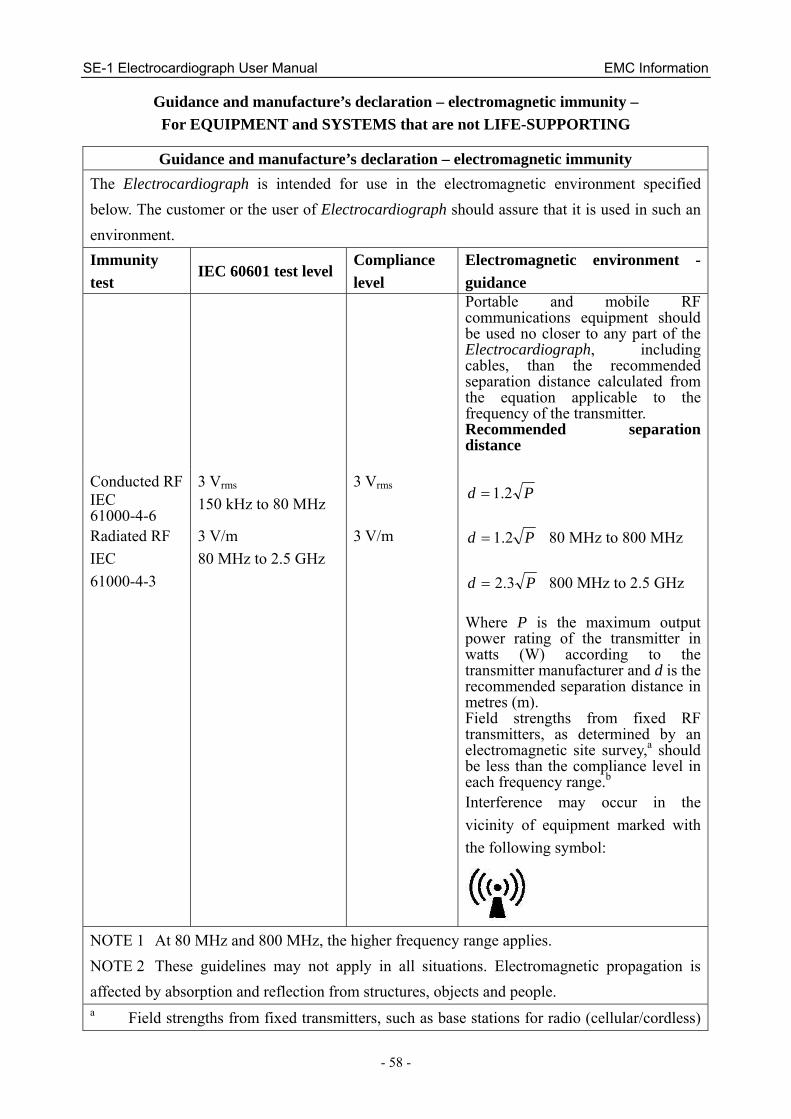
SE-1 Electrocardiograph User Manual EMC Information
- 58 -
Guidance and manufacture’s declaration – electromagnetic immunity – For EQUIPMENT and SYSTEMS that are not LIFE-SUPPORTING
Guidance and manufacture’s declaration – electromagnetic immunity The Electrocardiograph is intended for use in the electromagnetic environment specified below. The customer or the user of Electrocardiograph should assure that it is used in such an environment. Immunity test
IEC 60601 test level Compliance level
Electromagnetic environment - guidance
Portable and mobile RF communications equipment should be used no closer to any part of the Electrocardiograph, including cables, than the recommended separation distance calculated from the equation applicable to the frequency of the transmitter. Recommended separation distance
Conducted RF IEC 61000-4-6
3 Vrms 150 kHz to 80 MHz
3 Vrms Pd 2.1=
Radiated RF IEC 61000-4-3
3 V/m 80 MHz to 2.5 GHz
3 V/m Pd 2.1= 80 MHz to 800 MHz
Pd 3.2= 800 MHz to 2.5 GHz Where P is the maximum output power rating of the transmitter in watts (W) according to the transmitter manufacturer and d is the recommended separation distance in metres (m). Field strengths from fixed RF transmitters, as determined by an electromagnetic site survey,a should be less than the compliance level in each frequency range.b Interference may occur in the vicinity of equipment marked with the following symbol:
NOTE 1 At 80 MHz and 800 MHz, the higher frequency range applies. NOTE 2 These guidelines may not apply in all situations. Electromagnetic propagation is affected by absorption and reflection from structures, objects and people. a Field strengths from fixed transmitters, such as base stations for radio (cellular/cordless)

SE-1 Electrocardiograph User Manual EMC Information
- 59 -
telephones and land mobile radios, amateur radio, AM and FM radio broadcast and TV broadcast cannot be predicted theoretically with accuracy. To assess the electromagnetic environment due to fixed RF transmitters, an electromagnetic site survey should be considered. If the measured field strength in the location in which the Electrocardiograph is used exceeds the applicable RF compliance level above, the Electrocardiograph should be observed to verify normal operation. If abnormal performance is observed, additional measures may be necessary, such as reorienting or relocating the Electrocardiograph.
b Over the frequency range 150 kHz to 80 MHz, field strengths should be less than 3 V/m.
Recommended separation distances between portable and mobile RF communications equipment and the EQUIPMENT or SYSTEM –
For EQUIPMENT or SYSTEM that are not LIFE-SUPPORTING
Recommended separation distances between portable and mobile RF communications equipment and electrocardiograph
The electrocardiograph is intended for use in an electromagnetic environment in which radiated RF disturbances are controlled. The customer or the user of the electrocardiograph can help prevent electromagnetic interference by maintaining a minimum distance between portable and mobile RF communications equipment (transmitters) and the electrocardiograph as recommended below, according to the maximum output power of the communications equipment.
Rated maximum output power of
transmitter (W)
Separation distance according to frequency of transmitter (m)
150 kHz to 80 MHz Pd 2.1=
80 MHz to 800 MHzPd 2.1=
800 MHz to 2.5 GHz
Pd 3.2= 0.01 0.12 0.12 0.23 0.1 0.38 0.38 0.73 1 1.2 1.2 2.3 10 3.8 3.8 7.3 100 12 12 23
For transmitters rated at a maximum output power not listed above, the recommended separation distance d in meters (m) can be estimated using the equation applicable to the frequency of the transmitter, where P is the maximum output power rating of the transmitter in watts (W) according to the transmitter manufacturer. NOTE 1 At 80 MHz and 800 MHz, the separation distance for the higher frequency range applies. NOTE 2 These guidelines may not apply in all situations. Electromagnetic propagation is affected by absorption and reflection from structures, objects and people.

SE-1 Electrocardiograph User Manual Abbreviation
- 60 -
Appendix 3 Abbreviation
Abbr English
ECG Electrocardiogram/Electrocardiograph
HR Heart Rate
aVF Left Foot Augmented Lead
aVL Left Arm Augmented Lead
aVR Right Arm Augmented Lead
LA Left Arm
LL Left Leg
RA Right Arm
RL Right Leg
ID Identification
AC Alternating Current
USB Universal Serial Bus
AGC Auto Gain Control
