800af, type 39600/testmultimedia.3m.com/mws/media/462317o/3m-matic-case-sealer-800af...$10.00...
TRANSCRIPT
3M Masking and Packaging Systems Division
3M Center, Building 220-8W-01St. Paul, MN 55144-1000
It is recommended you
immediately order the
spare parts listed on
page 41. These parts
are expected to wear
through normal use
and should be kept on
hand to minimize
production delays.
Read "Safeguards", pages 3-6
and also operating
"Warnings", page 18
BEFORE INSTALLING OR
OPERATING THIS
EQUIPMENT.
Important SafetyInformation
Spare Parts
Serial No.For reference, record machine serial number here.
Instructions and Parts List
3M-Matic ™
800af Type 39600
Adjustable
Case Sealer
with
Taping Heads
"3M-Matic" and "AccuGlide" are Trademarksof 3M, St. Paul, MN 55144-1000
Litho in U.S.A.
© 3M 1997 44-0009-1931-4(B107.0)
AccuGlide IITM
Replacement Parts and Service Information
3M Packaging Systems Division
3M Center, Building 220-8W-01St. Paul, MN 55144-1000
To Our Customers:This is the 3M-Matic™/AccuGlide™/Scotch™ brand equipment youordered. It has been set up and tested in the factory with "Scotch" brandtapes. If technical assistance or replacement parts are needed, call or Faxthe appropriate number listed below.
Included with each machine is an Instructions and Parts List manual.
Replacement Parts and Additional Manuals
Order parts by part number, part description and quantity required. Also,
when ordering parts and/or additional manuals, include machine name,
number and type. A parts order form is provided at the back of this manual.
3M/Tape Dispenser Parts
241 Venture Drive 1-800/344 9883
Amery, WI 54001-1325 FAX# 715/268 8153
Technical Assistance:
3M-Matic™ Helpline – 1-800/328 1390. Please provide the customer support
coordinator with the machine number, machine type/model and serial number.
If you have a technical question that does not require an immediate response,
you may Fax it to 715/381 0248.
Minimum billing on parts orders will be $25.00. Replacement part prices available on request.
Note : Outside the U.S., contact the local 3M subsidiary for parts ordering information.
$10.00 restocking charge per invoice on returned parts.
"3M-Matic", "AccuGlide" and “Scotch” are trademarksof 3M, St. Paul, Minnesota 55144-1000
Printed in U.S.A.
© 3M 1999 44-0009-1851-4(E79.0)
Replacement Parts And Service Information
To Our Customers:This is the 3M-Matic™/AccuGlide™/Scotch™ brand equipment youordered. It has been set up and tested in the factory with "Scotch" brandtapes. If any problems occur when operating this equipment, and youdesire a service call, or phone consultation, call, write or Fax theappropriate number listed below.
Included with each machine is an Instructions and Parts List manual.
SERVICE, REPLACEMENT PARTS AND ADDITIONAL MANUALS
AVAILABLE DIRECT FROM:
Order parts by part number, part description and quantity required. Also, when
ordering parts and/or additional manuals, include machine name, number and
type.
1-800/328 1390
"3M-Matic", "AccuGlide" and “Scotch” are trademarksof 3M, St. Paul, Minnesota 55144-1000
Printed in U.S.A.
© 3M 1999 44-0009-1852-2(D79.0)
3M Packaging Systems Division
3M Center, Building 220-8W-01St. Paul, MN 55144-1000
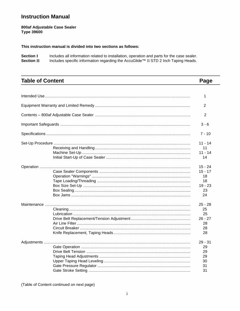
Instruction Manual
800af Adjustable Case SealerType 39600
Table of Content Page
Intended Use..................................................................................................................................... 1
Equipment Warranty and Limited Remedy ....................................................................................... 2
Contents – 800af Adjustable Case Sealer ....................................................................................... 2
Important Safeguards ....................................................................................................................... 3 - 6
Specifications .................................................................................................................................... 7 - 10
Set-Up Procedure ............................................................................................................................. 11 - 14Receiving and Handling ....................................................................................... 11Machine Set-Up ................................................................................................... 11 - 14Initial Start-Up of Case Sealer ............................................................................. 14
Operation .......................................................................................................................................... 15 - 24Case Sealer Components ................................................................................... 15 - 17Operation "Warnings" .......................................................................................... 18Tape Loading/Threading ..................................................................................... 18Box Size Set-Up .................................................................................................. 19 - 23Box Sealing .......................................................................................................... 23Box Jams ............................................................................................................. 24
Maintenance ..................................................................................................................................... 25 - 28Cleaning ............................................................................................................... 25Lubrication ........................................................................................................... 25Drive Belt Replacement/Tension Adjustment ...................................................... 26 - 27Air Line Filter ........................................................................................................ 28Circuit Breaker ..................................................................................................... 28Knife Replacement, Taping Heads ...................................................................... 28
Adjustments ...................................................................................................................................... 29 - 31Gate Operation .................................................................................................... 29Drive Belt Tension ............................................................................................... 29Taping Head Adjustments ................................................................................... 29Upper Taping Head Leveling ............................................................................... 30Gate Pressure Regulator ..................................................................................... 31Gate Stroke Setting ............................................................................................. 31
i
(Table of Content continued on next page)
This instruction manual is divided into two sections as follows:
Section I Includes all information related to installation, operation and parts for the case sealer.Section II Includes specific information regarding the AccuGlide™ II STD 2 Inch Taping Heads.
Table of Content (Continued) Page
Special Set-Up Procedure ................................................................................................................ 33 - 36Changing Drive Belt Height ................................................................................. 33Changing the Tape Leg Length ........................................................................... 34Outer Column Re-Positioning .............................................................................. 35 - 36
Troubleshooting ................................................................................................................................ 37 - 38Troubleshooting Guide ........................................................................................ 37 - 38
Pneumatic Diagram .......................................................................................................................... 39
Electrical Diagram ............................................................................................................................. 40 - 41
Spare and Miscellaneous Parts ........................................................................................................ 43Spare Parts .......................................................................................................... 43Label Kit ............................................................................................................... 43Tool and Parts Kit ................................................................................................ 43Replacement Parts Ordering Information and Service ....................................... 43
Options/Accessories ......................................................................................................................... 44
Replacement Parts Illustrations and Parts Lists ..................................................... (Yellow Section) 45 - 89
Section II – AccuGlide ™ STD 2 Inch Taping Heads(See Section II for Table of Contents)
i i
1
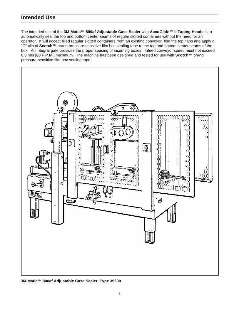
3M-Matic ™ 800af Adjustable Case Sealer, Type 39600
Intended Use
The intended use of the 3M-Matic ™ 800af Adjustable Case Sealer with AccuGlide ™ II Taping Heads is toautomatically seal the top and bottom center seams of regular slotted containers without the need for anoperator. It will accept filled regular slotted containers from an existing conveyor, fold the top flaps and apply a"C" clip of Scotch ™ brand pressure-sensitive film box sealing tape to the top and bottom center seams of thebox. An integral gate provides the proper spacing of incoming boxes. Infeed conveyor speed must not exceed0.3 m/s [60 F.P.M.] maximum. The machine has been designed and tested for use with Scotch ™ brandpressure-sensitive film box sealing tape.
2
Contents – 800af Adjustable Case Sealer
(1) 800af Adjustable Case Sealer, Type 39600(1) Tool/Spare Parts Kit, P/N 78-8060-8476-6(1) Instruction and Parts Manual
Scotch TM, AccuGlide TM, and 3M-Matic TM are Trademarks of 3M, St. Paul, Minnesota 55144-1000
Equipment Warranty and Limited Remedy: THE FOLLOWING WARRANTY IS MADE IN LIEU OF ALLOTHER WARRANTIES, EXPRESS OR IMPLIED, INCLUDING, BUT NOT LIMITED TO, THE IMPLIEDWARRANTY OF MERCHANTABILITY, THE IMPLIED WARRANTY OF FITNESS FOR A PARTICULARPURPOSE AND ANY IMPLIED WARRANTY ARISING OUT OF A COURSE OF DEALING, A CUSTOM ORUSAGE OF TRADE:
3M sells its 3M-Matic ™ 800af Type 39600 with the following warranties: 1. The drive belts and the taping head knives, springs and rollers will be free from all defects M»é ninety (90)
days after delivery. 2. All other taping head parts will be free from all defects for three (3) years after delivery. 3. All other parts will be free from all defects for two (2) years after delivery.
If any part is proved to be defective within its warranty period, then the exclusive remedy and 3M’s and seller’ssole obligation shall be, at 3M’s option, to repair or replace the part, provided the defective part is returnedimmediately to 3M’s factory or an authorized service station designated by 3M. A part will be presumed to havebecome defective after its warranty period unless the part is received or 3M is notified of the problem no laterthan five (5) calendar days after the warranty period. If 3M is unable to repair or replace the part within areasonable time, then 3M at its option, will replace the equipment or refund the purchase price. 3M shall haveno obligation to provide or pay for the labor required to install the repaired or replacement part. 3M shall haveno obligation to repair or replace (1) those parts failing due to operator misuse, carelessness, or due to anyaccidental cause other than equipment failure, or (2) parts failing due to non-lubrication, inadequate cleaning,improper operating environment, improper utilities or operator error.
Limitation of Liability: 3M and seller shall not be liable for direct, indirect, special, incidental or consequentialdamages based upon breach of warranty, breach of contract, negligence, strict liability or any other legal theory.
The foregoing Equipment Warranty and Limited Remedy and Limitation of Liability may be changed only by awritten agreement signed by authorized officers of 3M and seller.
3
Important Safeguards
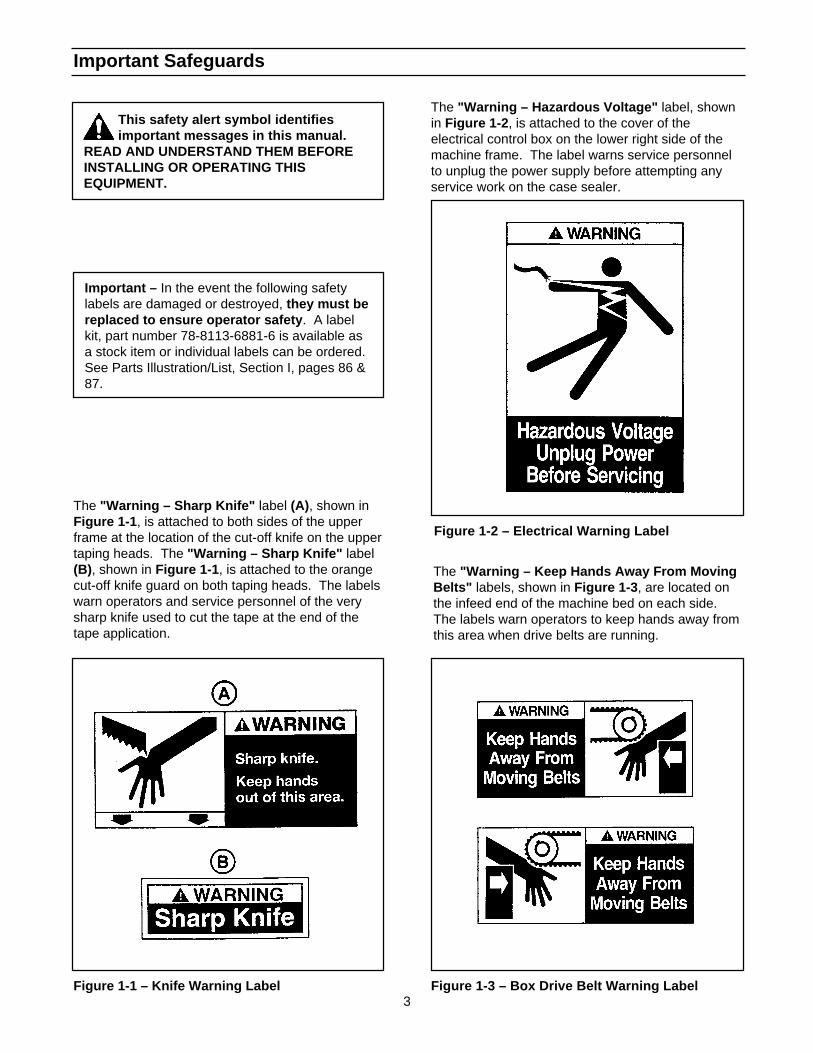
Figure 1-2 – Electrical Warning Label
Figure 1-3 – Box Drive Belt Warning Label
This safety alert symbol identifiesimportant messages in this manual.
READ AND UNDERSTAND THEM BEFOREINSTALLING OR OPERATING THISEQUIPMENT.
Important – In the event the following safetylabels are damaged or destroyed, they must bereplaced to ensure operator safety . A labelkit, part number 78-8113-6881-6 is available asa stock item or individual labels can be ordered.See Parts Illustration/List, Section I, pages 86 &87.
The "Warning – Sharp Knife" label (A), shown inFigure 1-1 , is attached to both sides of the upperframe at the location of the cut-off knife on the uppertaping heads. The "Warning – Sharp Knife" label(B), shown in Figure 1-1 , is attached to the orangecut-off knife guard on both taping heads. The labelswarn operators and service personnel of the verysharp knife used to cut the tape at the end of thetape application.
The "Warning – Hazardous Voltage" label, shownin Figure 1-2 , is attached to the cover of theelectrical control box on the lower right side of themachine frame. The label warns service personnelto unplug the power supply before attempting anyservice work on the case sealer.
The "Warning – Keep Hands Away From MovingBelts" labels, shown in Figure 1-3 , are located onthe infeed end of the machine bed on each side.The labels warn operators to keep hands away fromthis area when drive belts are running.
Figure 1-1 – Knife Warning Label

4
Important Safeguards (Continued)
The "Warning – Moving Flap Kicker" labels,shown in Figure 1-4, are attached to the machineguards on the infeed end, close to the top. Theselabels remind the operator and service personnel tokeep away from flap kicker when machine is running.
Two emergency stop switches are located, one oneach side of the machine, on the guard at the centerof the machine. The "Stop" label, shown in Figure1-6, is located near these switches and remindoperators and other personnel of the function ofthese switches.
Figure 1-4 – Moving Flap Kicker
The "Caution – Pinch Point" label, shown inFigure 1-5 , is attached to the back side of thecompression roller brackets on both sides of themachine. The label reminds operator to keep handsaway from compression rollers when machine isrunning.
Figure 1-6 – Stop and On/Off Labels
The "On/Off" label, shown in Figure 1-7, is locatednext to the electrical on/off switch on the guard (leftside) at the infeed end of the machine. The labelreminds operators of the function of this switch.
Figure 1-5 – Pinch Point Caution Label Figure 1-7 – On/Off Label
5
Important Safeguards (Continued)
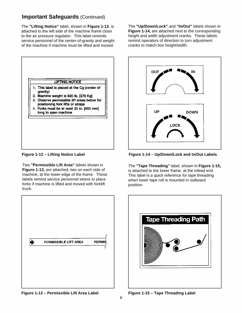
The "On/Off" label, shown in Figure 1-10, isattached to the frame above the On/Off valve andreminds operators of the location of this valve andits function.
Two "Operating Notice" labels, shown inFigure 1-11 , are located on the top, infeed end ofboth drive belt assemblies. The labels remindoperators of correct belt adjustment procedures.
Figure 1-10 – On/Off Label
Figure 1-11 – Operating Notice Label
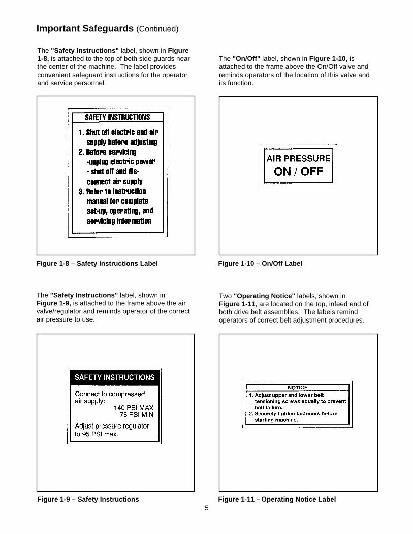
The "Safety Instructions" label, shown in Figure1-8, is attached to the top of both side guards nearthe center of the machine. The label providesconvenient safeguard instructions for the operatorand service personnel.
Figure 1-8 – Safety Instructions Label
The "Safety Instructions" label, shown inFigure 1-9, is attached to the frame above the airvalve/regulator and reminds operator of the correctair pressure to use.
Figure 1-9 – Safety Instructions
6
Important Safeguards (Continued)
Figure 1-14 – Up/Down/Lock and In/Out Labels
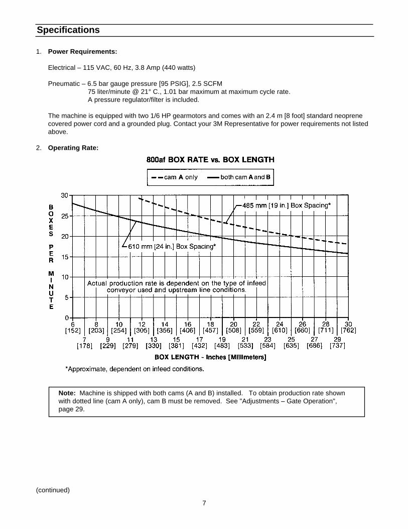
The "Lifting Notice" label, shown in Figure 1-12 , isattached to the left side of the machine frame closeto the air pressure regulator. This label remindsservice personnel of the center-of-gravity and weightof the machine if machine must be lifted and moved.
Two "Permissible Lift Area" labels shown inFigure 1-13, are attached, two on each side ofmachine, at the lower edge of the frame. Theselabels remind service personnel where to placeforks if machine is lifted and moved with forklifttruck.
Figure 1-15 – Tape Threading Label
The "Up/Down/Lock" and "In/Out" labels shown inFigure 1-14, are attached next to the correspondingheight and width adjustment cranks. These labelsremind operators of direction to turn adjustmentcranks to match box height/width.
Figure 1-12 – Lifting Notice Label
The "Tape Threading" label, shown in Figure 1-15,is attached to the lower frame, at the infeed end.This label is a quick reference for tape threadingwhen lower tape roll is mounted in outboardposition.
Figure 1-13 – Permissible Lift Area Label
7
Specifications
(continued)
1. Power Requirements:
Electrical – 115 VAC, 60 Hz, 3.8 Amp (440 watts)
Pneumatic – 6.5 bar gauge pressure [95 PSIG], 2.5 SCFM 75 liter/minute @ 21° C., 1.01 bar maximum at maximum cycle rate. A pressure regulator/filter is included.
The machine is equipped with two 1/6 HP gearmotors and comes with an 2.4 m [8 foot] standard neoprenecovered power cord and a grounded plug. Contact your 3M Representative for power requirements not listedabove.
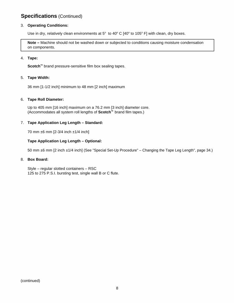
2. Operating Rate:
Note: Machine is shipped with both cams (A and B) installed. To obtain production rate shownwith dotted line (cam A only), cam B must be removed. See "Adjustments – Gate Operation",page 29.
8
IMPORTANT SAFEGUARDIMPORTANT SAFEGUARD
Specifications (Continued)
(continued)
5. Tape Width:
36 mm [1-1/2 inch] minimum to 48 mm [2 inch] maximum
6. Tape Roll Diameter:
Up to 405 mm [16 inch] maximum on a 76.2 mm [3 inch] diameter core.(Accommodates all system roll lengths of Scotch TM brand film tapes.)
7. Tape Application Leg Length – Standard:
70 mm ±6 mm [2-3/4 inch ±1/4 inch]
Tape Application Leg Length – Optional:
50 mm ±6 mm [2 inch ±1/4 inch] (See "Special Set-Up Procedure" – Changing the Tape Leg Length", page 34.)
8. Box Board:
Style – regular slotted containers – RSC125 to 275 P.S.I. bursting test, single wall B or C flute.
3. Operating Conditions:
Use in dry, relatively clean environments at 5o to 40o C [40o to 105o F] with clean, dry boxes.
Note – Machine should not be washed down or subjected to conditions causing moisture condensationon components.
4. Tape:
Scotch TM brand pressure-sensitive film box sealing tapes.
9
(continued)
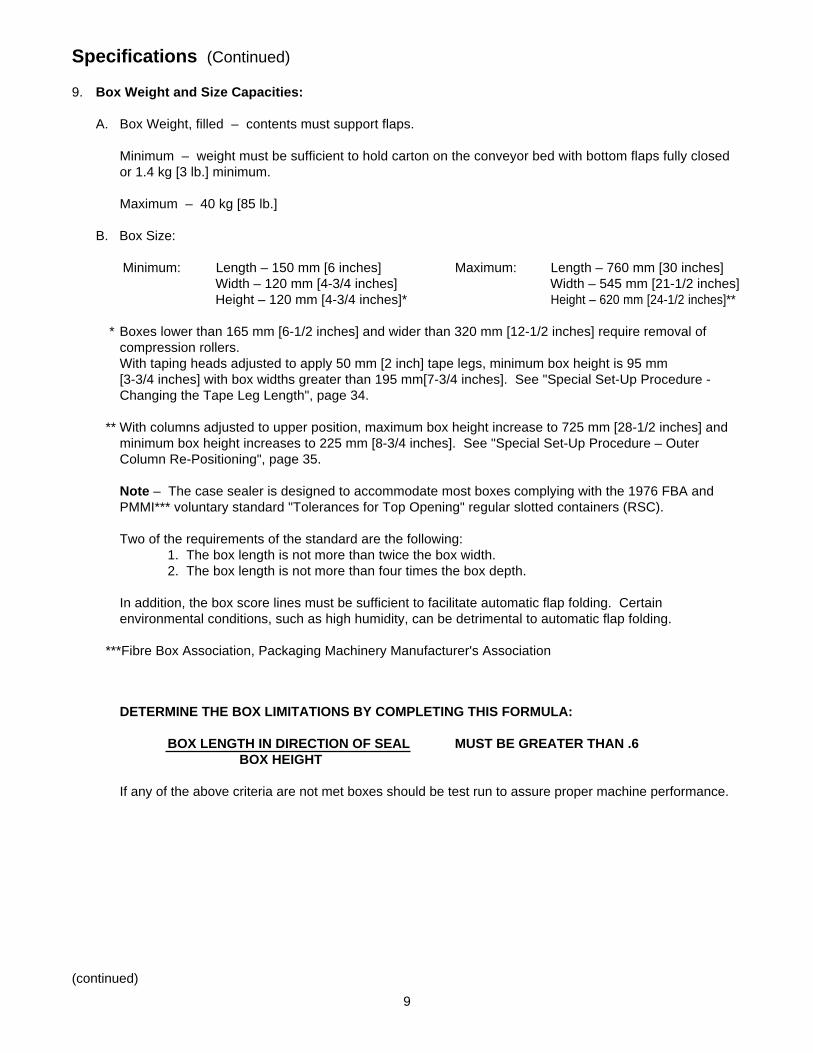
DETERMINE THE BOX LIMITATIONS BY COMPLETING THIS FORMULA:
BOX LENGTH IN DIRECTION OF SEAL MUST BE GREATER THAN .6BOX HEIGHT
If any of the above criteria are not met boxes should be test run to assure proper machine performance.
Specifications (Continued)
9. Box Weight and Size Capacities:
A. Box Weight, filled – contents must support flaps.
Minimum – weight must be sufficient to hold carton on the conveyor bed with bottom flaps fully closedor 1.4 kg [3 lb.] minimum.
Maximum – 40 kg [85 lb.]
B. Box Size:
Minimum: Length – 150 mm [6 inches] Maximum: Length – 760 mm [30 inches]Width – 120 mm [4-3/4 inches] Width – 545 mm [21-1/2 inches]Height – 120 mm [4-3/4 inches]* Height – 620 mm [24-1/2 inches]**
* Boxes lower than 165 mm [6-1/2 inches] and wider than 320 mm [12-1/2 inches] require removal ofcompression rollers.With taping heads adjusted to apply 50 mm [2 inch] tape legs, minimum box height is 95 mm[3-3/4 inches] with box widths greater than 195 mm[7-3/4 inches]. See "Special Set-Up Procedure -Changing the Tape Leg Length", page 34.
** With columns adjusted to upper position, maximum box height increase to 725 mm [28-1/2 inches] andminimum box height increases to 225 mm [8-3/4 inches]. See "Special Set-Up Procedure – OuterColumn Re-Positioning", page 35.
Note – The case sealer is designed to accommodate most boxes complying with the 1976 FBA andPMMI*** voluntary standard "Tolerances for Top Opening" regular slotted containers (RSC).
Two of the requirements of the standard are the following:1. The box length is not more than twice the box width.2. The box length is not more than four times the box depth.
In addition, the box score lines must be sufficient to facilitate automatic flap folding. Certainenvironmental conditions, such as high humidity, can be detrimental to automatic flap folding.
***Fibre Box Association, Packaging Machinery Manufacturer's Association
10
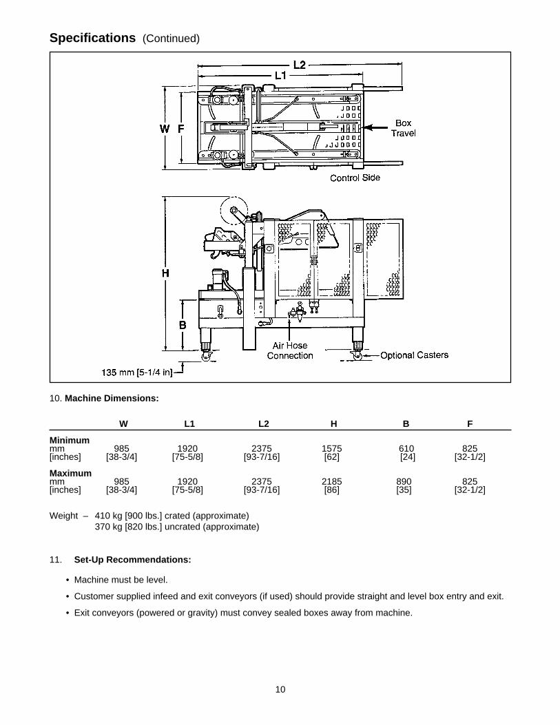
10. Machine Dimensions:
W L1 L2 H B F
Minimummm 985 1920 2375 1575 610 825[inches] [38-3/4] [75-5/8] [93-7/16] [62] [24] [32-1/2]
Maximummm 985 1920 2375 2185 890 825[inches] [38-3/4] [75-5/8] [93-7/16] [86] [35] [32-1/2]
Weight – 410 kg [900 lbs.] crated (approximate)370 kg [820 lbs.] uncrated (approximate)
11. Set-Up Recommendations:
• Machine must be level.
• Customer supplied infeed and exit conveyors (if used) should provide straight and level box entry and exit.
• Exit conveyors (powered or gravity) must convey sealed boxes away from machine.
Specifications (Continued)
11
Installation and Set-Up
Machine Set-Up
Receiving And Handling
After the machine has been uncrated, examine the case sealer for damage that might have occurred duringtransit. If damage is evident, file a damage claim immediately with the transportation company and alsonotify your 3M Representative.
It is recommended that the case sealer be set-up and operated with product before placing it in the productionline. This approach will allow your thorough review and familiarization with the 800af before subjecting it andoperating personnel to a production situation where time for set-up, adjustments, and operator training usuallybecomes limited.
The following instructions are presented in the order recommended for setting up and installing the case sealer.Following them step by step will result in an installation in your production line that best utilizes the many featuresbuilt into the case sealer. Refer to Figure 3-1 and 3-2 to identify the various components and controls of themachine.
IMPORTANT – Read "Warnings" on page 18 before attempting to set-up the case sealer for operation.
For future reference, record machine serial number on front cover of this instruction manual in the spaceprovided.
1. Follow "Unpacking Instructions" label attached to corrugated packing cover.
2. Use appropriate material handling equipment to remove the machine from the pallet and move it into position.
Whenever the machine is lifted with a fork truck, insure that the forks span completely across the machineframe and do not contact any wiring or mechanism under the machine frame. In some cases the lower tapinghead may need to be removed to avoid damage.
CAUTION – Machine weighs approximately 370 kg [820 lbs] uncrated.
2. Remove and discard cable ties on upper head assembly.
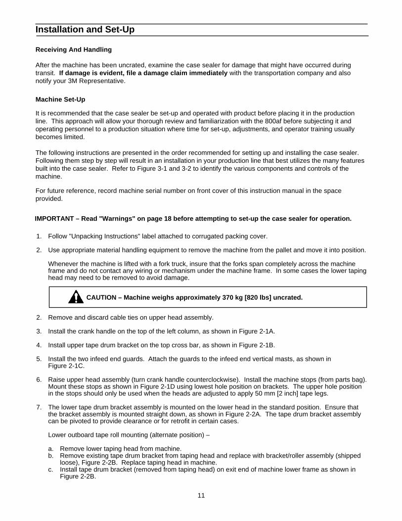
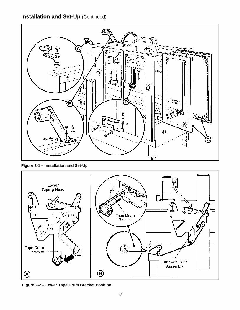
3. Install the crank handle on the top of the left column, as shown in Figure 2-1A.
4. Install upper tape drum bracket on the top cross bar, as shown in Figure 2-1B.
5. Install the two infeed end guards. Attach the guards to the infeed end vertical masts, as shown inFigure 2-1C.
6. Raise upper head assembly (turn crank handle counterclockwise). Install the machine stops (from parts bag).Mount these stops as shown in Figure 2-1D using lowest hole position on brackets. The upper hole positionin the stops should only be used when the heads are adjusted to apply 50 mm [2 inch] tape legs.
7. The lower tape drum bracket assembly is mounted on the lower head in the standard position. Ensure thatthe bracket assembly is mounted straight down, as shown in Figure 2-2A. The tape drum bracket assemblycan be pivoted to provide clearance or for retrofit in certain cases.
Lower outboard tape roll mounting (alternate position) –
a. Remove lower taping head from machine.b. Remove existing tape drum bracket from taping head and replace with bracket/roller assembly (shipped
loose), Figure 2-2B. Replace taping head in machine.c. Install tape drum bracket (removed from taping head) on exit end of machine lower frame as shown in
Figure 2-2B.
12
Installation and Set-Up (Continued)
Figure 2-1 – Installation and Set-Up
Figure 2-2 – Lower Tape Drum Bracket Position
13
Installation and Set-Up (Continued)
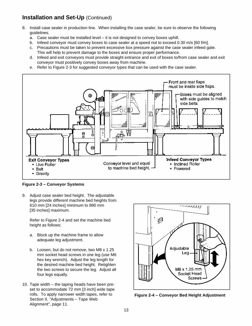
8. Install case sealer in production line. When installing the case sealer, be sure to observe the followingguidelines.a. Case sealer must be installed level – it is not designed to convey boxes uphill.b. Infeed conveyor must convey boxes to case sealer at a speed not to exceed 0.30 m/s [60 f/m].c. Precautions must be taken to prevent excessive box pressure against the case sealer infeed gate.
This will help to prevent damage to the boxes and ensure proper performance.d. Infeed and exit conveyors must provide straight entrance and exit of boxes to/from case sealer and exit
conveyor must positively convey boxes away from machine.e. Refer to Figure 2-3 for suggested conveyor types that can be used with the case sealer.
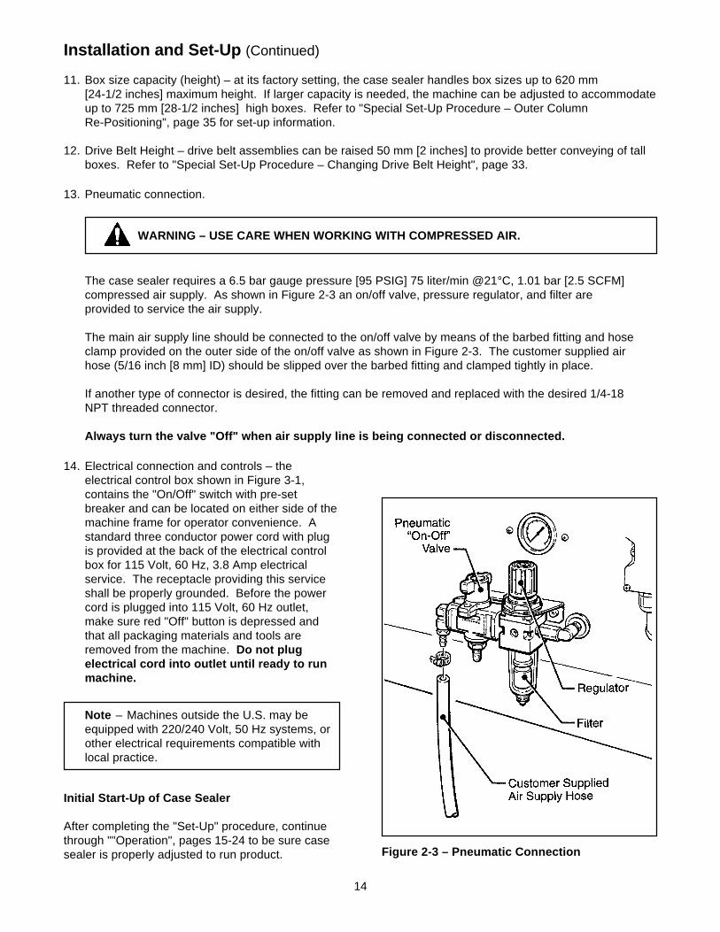
9. Adjust case sealer bed height. The adjustablelegs provide different machine bed heights from610 mm [24 inches] minimum to 890 mm[35 inches] maximum.
Refer to Figure 2-4 and set the machine bedheight as follows:
a. Block up the machine frame to allowadequate leg adjustment.
b. Loosen, but do not remove, two M8 x 1.25mm socket head screws in one leg (use M6hex key wrench). Adjust the leg length forthe desired machine bed height. Retightenthe two screws to secure the leg. Adjust allfour legs equally.
10. Tape width – the taping heads have been pre-set to accommodate 72 mm [3 inch] wide taperolls. To apply narrower width tapes, refer toSection II, "Adjustments – Tape WebAlignment", page 11.
Figure 2-4 – Conveyor Bed Height Adjustment
Figure 2-3 – Conveyor Systems
14
Installation and Set-Up (Continued)
11. Box size capacity (height) – at its factory setting, the case sealer handles box sizes up to 620 mm[24-1/2 inches] maximum height. If larger capacity is needed, the machine can be adjusted to accommodateup to 725 mm [28-1/2 inches] high boxes. Refer to "Special Set-Up Procedure – Outer ColumnRe-Positioning", page 35 for set-up information.
12. Drive Belt Height – drive belt assemblies can be raised 50 mm [2 inches] to provide better conveying of tallboxes. Refer to "Special Set-Up Procedure – Changing Drive Belt Height", page 33.
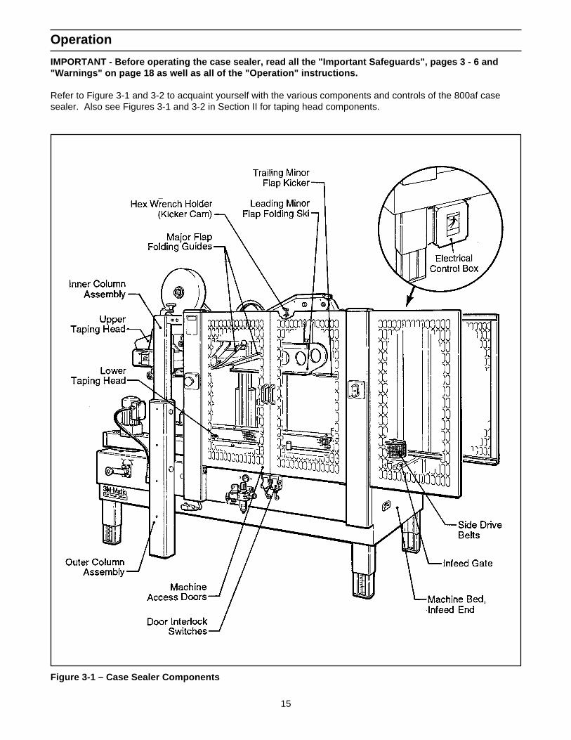
13. Pneumatic connection.
WARNING – USE CARE WHEN WORKING WITH COMPRESSED AIR.
The case sealer requires a 6.5 bar gauge pressure [95 PSIG] 75 liter/min @21°C, 1.01 bar [2.5 SCFM]compressed air supply. As shown in Figure 2-3 an on/off valve, pressure regulator, and filter areprovided to service the air supply.
The main air supply line should be connected to the on/off valve by means of the barbed fitting and hoseclamp provided on the outer side of the on/off valve as shown in Figure 2-3. The customer supplied airhose (5/16 inch [8 mm] ID) should be slipped over the barbed fitting and clamped tightly in place.
If another type of connector is desired, the fitting can be removed and replaced with the desired 1/4-18NPT threaded connector.
Always turn the valve "Off" when air supply line is being connected or disconnected.
Figure 2-3 – Pneumatic Connection
Initial Start-Up of Case Sealer
After completing the "Set-Up" procedure, continuethrough ""Operation", pages 15-24 to be sure casesealer is properly adjusted to run product.
Note – Machines outside the U.S. may beequipped with 220/240 Volt, 50 Hz systems, orother electrical requirements compatible withlocal practice.
14. Electrical connection and controls – theelectrical control box shown in Figure 3-1,contains the "On/Off" switch with pre-setbreaker and can be located on either side of themachine frame for operator convenience. Astandard three conductor power cord with plugis provided at the back of the electrical controlbox for 115 Volt, 60 Hz, 3.8 Amp electricalservice. The receptacle providing this serviceshall be properly grounded. Before the powercord is plugged into 115 Volt, 60 Hz outlet,make sure red "Off" button is depressed andthat all packaging materials and tools areremoved from the machine. Do not plugelectrical cord into outlet until ready to runmachine.
15
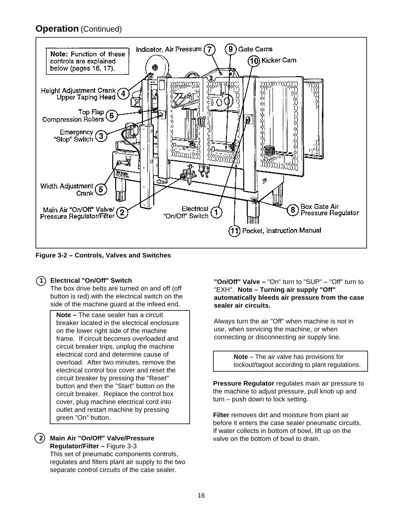
Operation
IMPORTANT - Before operating the case sealer, read all the "Important Safeguards", pages 3 - 6 and"Warnings" on page 18 as well as all of the "Operation" instructions.
Refer to Figure 3-1 and 3-2 to acquaint yourself with the various components and controls of the 800af casesealer. Also see Figures 3-1 and 3-2 in Section II for taping head components.
Figure 3-1 – Case Sealer Components
16
Operation (Continued)
Figure 3-2 – Controls, Valves and Switches
1 Electrical "On/Off" SwitchThe box drive belts are turned on and off (offbutton is red) with the electrical switch on theside of the machine guard at the infeed end.
Note – The air valve has provisions forlockout/tagout according to plant regulations.
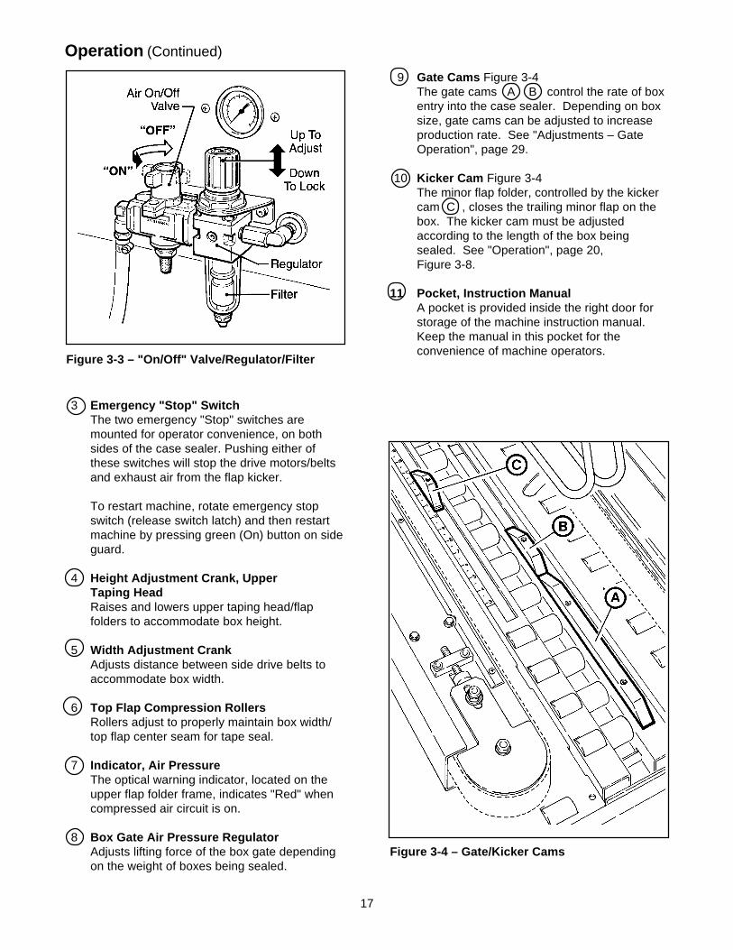
2 Main Air "On/Off" Valve/PressureRegulator/Filter – Figure 3-3This set of pneumatic components controls,regulates and filters plant air supply to the twoseparate control circuits of the case sealer.
Pressure Regulator regulates main air pressure tothe machine to adjust pressure, pull knob up andturn – push down to lock setting.
Filter removes dirt and moisture from plant airbefore it enters the case sealer pneumatic circuits.If water collects in bottom of bowl, lift up on thevalve on the bottom of bowl to drain.
"On/Off" Valve – "On" turn to "SUP" – "Off" turn to"EXH". Note – Turning air supply "Off"automatically bleeds air pressure from the casesealer air circuits.
Always turn the air "Off" when machine is not inuse, when servicing the machine, or whenconnecting or disconnecting air supply line.
Note – The case sealer has a circuitbreaker located in the electrical enclosureon the lower right side of the machineframe. If circuit becomes overloaded andcircuit breaker trips, unplug the machineelectrical cord and determine cause ofoverload. After two minutes, remove theelectrical control box cover and reset thecircuit breaker by pressing the "Reset"button and then the "Start" button on thecircuit breaker. Replace the control boxcover, plug machine electrical cord intooutlet and restart machine by pressinggreen "On" button.
17
Operation (Continued)
3 Emergency "Stop" SwitchThe two emergency "Stop" switches aremounted for operator convenience, on bothsides of the case sealer. Pushing either ofthese switches will stop the drive motors/beltsand exhaust air from the flap kicker.
To restart machine, rotate emergency stopswitch (release switch latch) and then restartmachine by pressing green (On) button on sideguard.
4 Height Adjustment Crank, UpperTaping HeadRaises and lowers upper taping head/flapfolders to accommodate box height.
5 Width Adjustment CrankAdjusts distance between side drive belts toaccommodate box width.
6 Top Flap Compression RollersRollers adjust to properly maintain box width/top flap center seam for tape seal.
7 Indicator, Air PressureThe optical warning indicator, located on theupper flap folder frame, indicates "Red" whencompressed air circuit is on.
8 Box Gate Air Pressure RegulatorAdjusts lifting force of the box gate dependingon the weight of boxes being sealed.
9 Gate Cams Figure 3-4The gate cams A B control the rate of boxentry into the case sealer. Depending on boxsize, gate cams can be adjusted to increaseproduction rate. See "Adjustments – GateOperation", page 29.
10 Kicker Cam Figure 3-4The minor flap folder, controlled by the kickercam C , closes the trailing minor flap on thebox. The kicker cam must be adjustedaccording to the length of the box beingsealed. See "Operation", page 20,Figure 3-8.
11 Pocket, Instruction ManualA pocket is provided inside the right door forstorage of the machine instruction manual.Keep the manual in this pocket for theconvenience of machine operators.
Figure 3-4 – Gate/Kicker Cams
Figure 3-3 – "On/Off" Valve/Regulator/Filter
18
WARNINGS
Operation (Continued)
1. Turn electrical and air supply off and disconnect before servicing taping heads or performingany adjustments or maintenance on the machine. Turn electrical and air supplies off whenmachine is not in use.
2. Do not leave machine running unattended.
3. Before turning drive belts on, be sure no tools or other objects are on the machine bed.
4. Keep hands and loose clothing away from moving belts and flap kicker.
5. Keep away from flap kicker. Flap kicker is controlled by air and can be activated (if air supplyis "On") by depressing flap kicker cam. Be sure flap kicker is in the down position beforeservicing.
6. Never attempt to remove jammed boxes from the machine while machine is running.
7. Machine access door must be closed when drive belts are running. Do not attempt to overridedoor interlock switch.
8. Keep hands and clothing away from taping heads when machine is running. A box travelingthrough the machine causes taping head rollers to retract when box enters and extend as boxleaves taping head.
9. Both the upper and lower taping heads utilize extremely sharp tape cut-off knives. The knife islocated under the orange knife guard which has the "WARNING – SHARP KNIFE" label. Beforeloading tape, refer to Figures 3-1 and 3-2 in Section II to identify the knife location. Keephands out of these areas except as necessary to service the taping heads.
10. Failure to comply with these warnings could result in severe personal injury and/or equipmentdamage.
Tape Loading/Threading – Upper Taping Head
See Section II , Pages 7 and 8
Tape Loading/Threading – Lower Taping HeadWith Tape Drum On Taping Head
See Section II , Pages 7 and 8
Tape Loading/Threading – Lower Taping HeadWith Alternate Outboard Tape Drum
CAUTION – Taping head weighsapproximately 7.2 kg [16 pounds]
without tape. Use proper bodymechanics when removing or installingtaping head.
1. Raise upper taping head high enough to allowclearance for removing lower taping head.
2. Remove lower taping head from machine bedand install threading needle as explained inSection II , page 7.
3. Replace taping head back into machine.
4. Place tape roll on outboard tape drum withadhesive side down on lead end of tape. (Seattape roll fully against back flange of tape drum.)Thread tape through outboard tape rollers asshown in Figure 3-5 and adhere tape lead endto lower end of threading needle.
5. Complete tape threading as explained inSection II , page 8.
19
Operation (Continued)
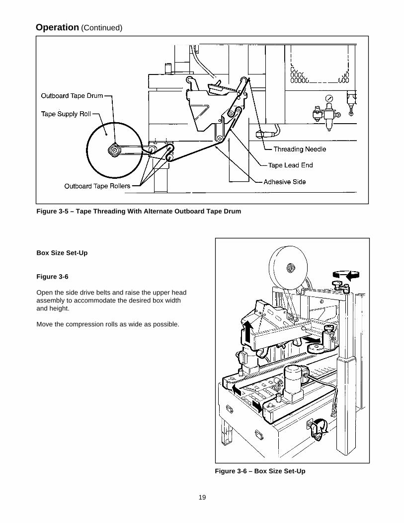
Figure 3-5 – Tape Threading With Alternate Outboard Tape Drum
Figure 3-6 – Box Size Set-Up
Box Size Set-Up
Figure 3-6
Open the side drive belts and raise the upper headassembly to accommodate the desired box widthand height.
Move the compression rolls as wide as possible.
20
Operation (Continued)
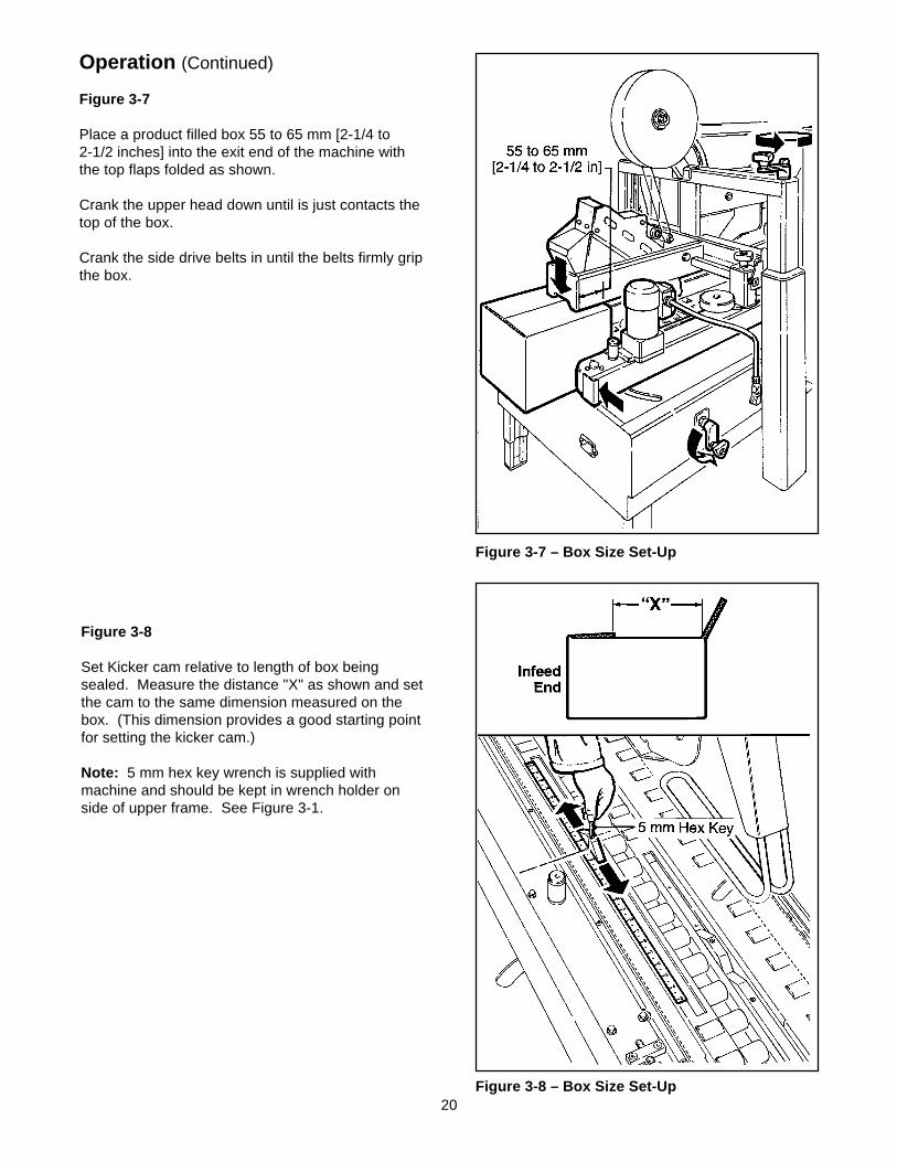
Figure 3-7 – Box Size Set-Up
Figure 3-8 – Box Size Set-Up
Figure 3-7
Place a product filled box 55 to 65 mm [2-1/4 to2-1/2 inches] into the exit end of the machine withthe top flaps folded as shown.
Crank the upper head down until is just contacts thetop of the box.
Crank the side drive belts in until the belts firmly gripthe box.
Figure 3-8
Set Kicker cam relative to length of box beingsealed. Measure the distance "X" as shown and setthe cam to the same dimension measured on thebox. (This dimension provides a good starting pointfor setting the kicker cam.)
Note: 5 mm hex key wrench is supplied withmachine and should be kept in wrench holder onside of upper frame. See Figure 3-1.
21
Operation (Continued)
Figure 3-9 – Box Size Set-Up
Figure 3-10 – Box Size Set-Up
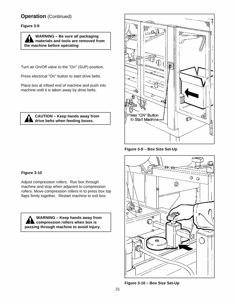
Figure 3-9
WARNING – Be sure all packagingmaterials and tools are removed from
the machine before operating
Turn air On/Off valve to the "On" (SUP) position.
Press electrical "On" button to start drive belts.
Place box at infeed end of machine and push intomachine until it is taken away by drive belts.
CAUTION – Keep hands away fromdrive belts when feeding boxes.
Figure 3-10
Adjust compression rollers. Run box throughmachine and stop when adjacent to compressionrollers. Move compression rollers in to press box topflaps firmly together. Restart machine to exit box.
WARNING – Keep hands away fromcompression rollers when box is
passing through machine to avoid injury.
22
Operation (Continued)
Figure 3-12 – Box Size Set-Up
Figure 3-11 – Box Size Set-Up
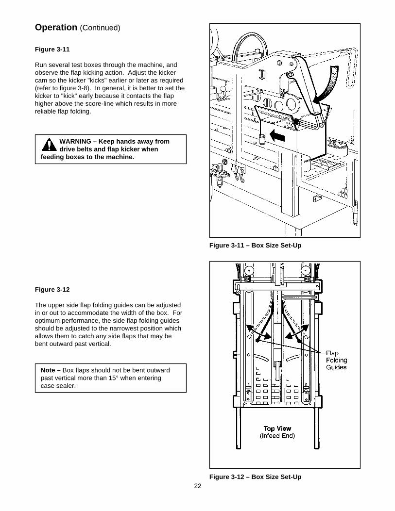
Figure 3-11
Run several test boxes through the machine, andobserve the flap kicking action. Adjust the kickercam so the kicker "kicks" earlier or later as required(refer to figure 3-8). In general, it is better to set thekicker to "kick" early because it contacts the flaphigher above the score-line which results in morereliable flap folding.
WARNING – Keep hands away fromdrive belts and flap kicker when
feeding boxes to the machine.
Figure 3-12
The upper side flap folding guides can be adjustedin or out to accommodate the width of the box. Foroptimum performance, the side flap folding guidesshould be adjusted to the narrowest position whichallows them to catch any side flaps that may bebent outward past vertical.
Note – Box flaps should not be bent outwardpast vertical more than 15° when enteringcase sealer.
23
Operation (Continued)
Notes:1. Box drive motors are designed to run at a moderate temperature of 40° C [104° F]. In some cases they
may feel hot to the touch.
2. Adjustment of the machine or taping heads are described in the "Adjustment" section of this manual.
CAUTION – If drive belts are allowed toslip on box, excessive belt wear will
occur.
Figure 3-13 – Box Size Set-UpBox Sealing
WARNINGS1. Remove tools or other objects from machine bed before starting machine.
2. Keep hands and loose clothing away from moving belts, flap kicker and flap kicker cam.
3. When feeding boxes to the machine by hand, push box in from end only – DO NOT PUSHWITH HANDS ON ANY CORNER OF THE BOX.
5. Never attempt to remove jammed boxes from the machine while machine is running.See "Box Jams", page 24.
1. Connect electrical and air supplies.
2. Turn main air valve "On" and adjust air regulator if pressure does not read 5 bar gauge pressure [70 PSIG].
3. Press electrical "On" button to start drive belts.
4. Continually feed boxes to case sealer, case sealer will automatically space entrance of boxes to machine.
5. Turn electrical and air supplies "Off" when machine is not in use.
6. Reload and thread tape as necessary.
7. Be sure machine is cleaned and lubricated according to recommendations in "Maintenance" section of thismanual.
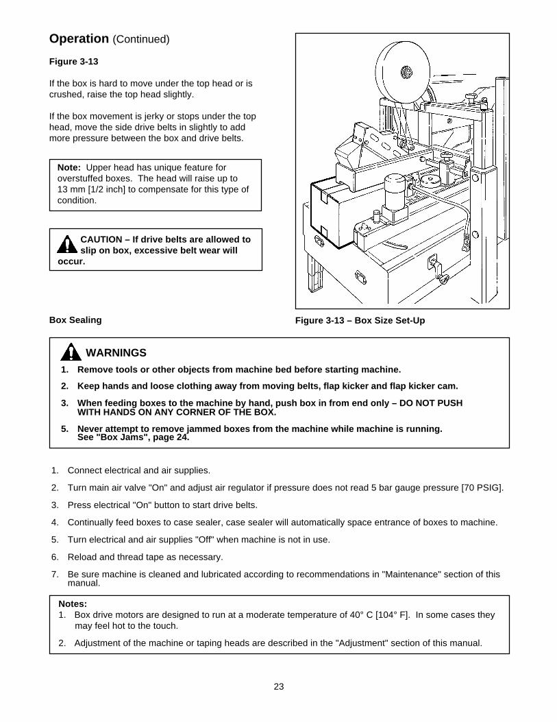
Figure 3-13
If the box is hard to move under the top head or iscrushed, raise the top head slightly.
If the box movement is jerky or stops under the tophead, move the side drive belts in slightly to addmore pressure between the box and drive belts.
Note: Upper head has unique feature foroverstuffed boxes. The head will raise up to13 mm [1/2 inch] to compensate for this type ofcondition.
24
Operation (Continued)
Box Jams
If a box is improperly fabricated or filled, if the machine is mis-adjusted for the box being run, or if boxes enterthe machine incorrectly, a box jam may occur. To clear a box jam, follow these steps:
1. Determine cause of box jam so corrective action can be taken to prevent reoccurrence.
2. Turn off machine.
1. Turn off and disconnect air and electrical supplies before attempting to remove jammedbox or serious injury could occur.
2. Wait for flap kicker to reach down position as shown in Figure 3-11, to avoid being hit orstartled by its movement.
WARNINGS
3. Crank upper head up and/or drive belts out until box is free.
4. Carefully pull box out of machine.
1. Keep hands away from upper and lower taping head cut-off knife as knife is extremelysharp and can cause severe injury.
2. When reaching into the machine to remove a jammed box, use proper posture toprevent back or other injuries.
WARNINGS
5. Readjust upper head and drive belts according to "Machine Adjustment for Box Size" instructions on pages19 - 23.
6. Connect air and electrical supplies.
7. Turn machine "On" only when it is safe to do so!

25
Maintenance
The case sealer been designed for long, troublefree service. The machine will perform best when itreceives routine maintenance and cleaning.Machine components that fail or wear excessivelyshould be promptly repaired or replaced to preventdamage to other portions of the machine or to theproduct.
Figure 4-1 – Lubrication Points, Frame
WARNING – Turn air and electricalsupplies off and disconnect before
beginning maintenance. Failure to complywith this warning could result in severepersonal injury or equipment damage.
Cleaning
Note – Never attempt to remove dirt by blowingit out with compressed air. This can cause thedirt to be blown inside the motor and ontosliding surfaces which may cause prematureequipment wear. Never wash down or subjectequipment to conditions causing moisturecondensation on components. Seriousequipment damage could result.
Regular slotted containers produce a great deal ofdust and paper chips when processed or handled inequipment. If this dust is allowed to build-up onmachine components, it can cause componentwear and overheating of drive motor. The dustbuild-up can best be removed from the machine by
Note – Wipe off excess oil and grease. It willattract dust and dirt which can cause prematureequipment wear and jamming. Take care thatoil and grease are not left on the surface ofrollers around which tape is threaded, as it cancontaminate the tape's adhesive.
a shop vacuum. Depending on the number andtype of boxes sealed in the case sealer, thiscleaning should be done approximately once permonth. If the boxes sealed are dirty, or if theenvironment in which the machine operates isdusty, cleaning on a more frequent basis may benecessary. Excessive dirt build-up that cannot beremoved by vacuuming should be wiped off with adamp cloth.
Lubrication
Most of the machine bearings, including the drivemotor, are permanently lubricated and sealed anddo not require additional lubricant.
Figure 4-1 illustrates the areas of the case sealerthat require lubrication. Lubricate points indicatedby arrows ( ) with SAE #30 non-detergent oiland points indicated by arrows ( ) with a smallamount of multi-purpose grease.
TAPING HEAD LUBRICATION – See Section II ,""Maintenance – Lubrication", page 10.
26
Maintenance (Continued)
WARNING – Turn air and electrical supplies off and disconnect before beginning maintenance.Failure to comply with this warning could result in severe personal injury or equipment
damage.
Drive Belt Replacement/Tension Adjustment
Note – 3M recommends the replacement of drive belts in pairs, especially if belts are unevenly worn.
REPLACEMENT – STEPS 1-11TENSION ADJUSTMENT – STEPS 1, 2, 4-6, 10 & 11
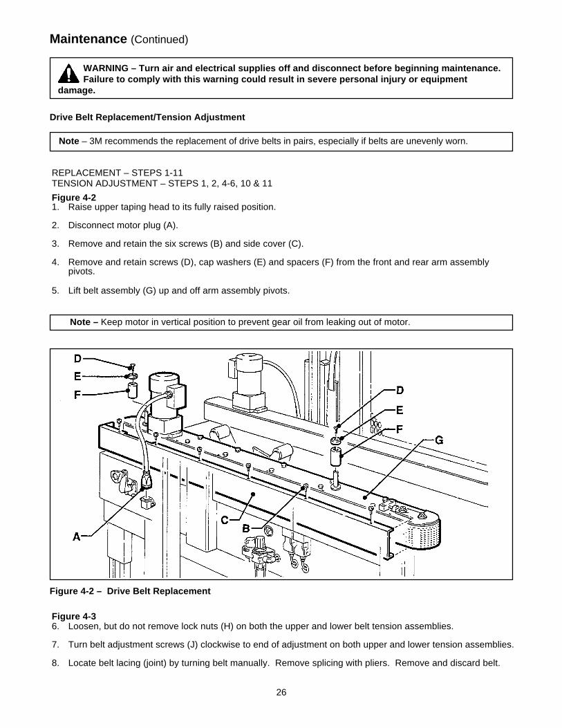
Figure 4-21. Raise upper taping head to its fully raised position.
2. Disconnect motor plug (A).
3. Remove and retain the six screws (B) and side cover (C).
4. Remove and retain screws (D), cap washers (E) and spacers (F) from the front and rear arm assemblypivots.
5. Lift belt assembly (G) up and off arm assembly pivots.
Note – Keep motor in vertical position to prevent gear oil from leaking out of motor.
Figure 4-2 – Drive Belt Replacement
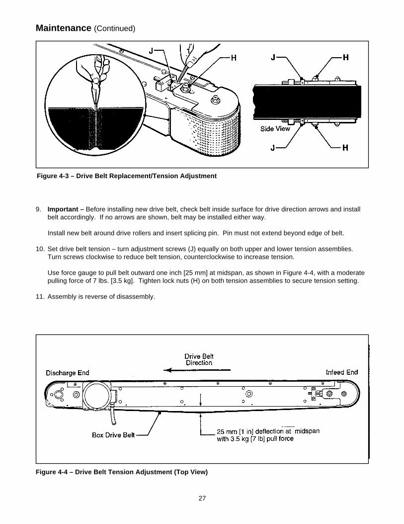
Figure 4-36. Loosen, but do not remove lock nuts (H) on both the upper and lower belt tension assemblies.
7. Turn belt adjustment screws (J) clockwise to end of adjustment on both upper and lower tension assemblies.
8. Locate belt lacing (joint) by turning belt manually. Remove splicing with pliers. Remove and discard belt.
27
Maintenance (Continued)
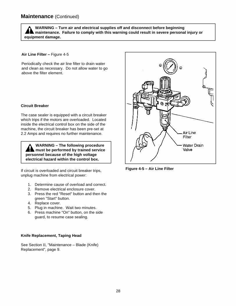
9. Important – Before installing new drive belt, check belt inside surface for drive direction arrows and installbelt accordingly. If no arrows are shown, belt may be installed either way.
Install new belt around drive rollers and insert splicing pin. Pin must not extend beyond edge of belt.
10. Set drive belt tension – turn adjustment screws (J) equally on both upper and lower tension assemblies.Turn screws clockwise to reduce belt tension, counterclockwise to increase tension.
Use force gauge to pull belt outward one inch [25 mm] at midspan, as shown in Figure 4-4, with a moderatepulling force of 7 lbs. [3.5 kg]. Tighten lock nuts (H) on both tension assemblies to secure tension setting.
11. Assembly is reverse of disassembly.
Figure 4-4 – Drive Belt Tension Adjustment (Top View)
Figure 4-3 – Drive Belt Replacement/Tension Adjustment
28
Maintenance (Continued)
WARNING – Turn air and electrical supplies off and disconnect before beginningmaintenance. Failure to comply with this warning could result in severe personal injury or
equipment damage.
WARNING – The following proceduremust be performed by trained service
personnel because of the high voltageelectrical hazard within the control box.
Circuit Breaker
The case sealer is equipped with a circuit breakerwhich trips if the motors are overloaded. Locatedinside the electrical control box on the side of themachine, the circuit breaker has been pre-set at2.2 Amps and requires no further maintenance.
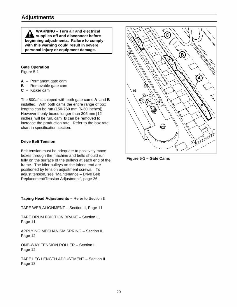
Air Line Filter – Figure 4-5
Periodically check the air line filter to drain waterand clean as necessary. Do not allow water to goabove the filter element.
Figure 4-5 – Air Line FilterIf circuit is overloaded and circuit breaker trips,unplug machine from electrical power:
1. Determine cause of overload and correct.2. Remove electrical enclosure cover.3. Press the red "Reset" button and then the
green "Start" button.4. Replace cover.5. Plug in machine. Wait two minutes.6. Press machine "On" button, on the side
guard, to resume case sealing.
Knife Replacement, Taping Head
See Section II , "Maintenance – Blade (Knife)Replacement", page 9.
29
Figure 5-1 – Gate Cams
Adjustments
WARNING – Turn air and electricalsupplies off and disconnect before
beginning adjustments. Failure to complywith this warning could result in severepersonal injury or equipment damage.
Gate OperationFigure 5-1
A – Permanent gate camB – Removable gate camC – Kicker cam
The 800af is shipped with both gate cams A and Binstalled. With both cams the entire range of boxlengths can be run (150-760 mm [6-30 inches]).However if only boxes longer than 305 mm [12inches] will be run, cam B can be removed toincrease the production rate. Refer to the box ratechart in specification section.
Drive Belt Tension
Belt tension must be adequate to positively moveboxes through the machine and belts should runfully on the surface of the pulleys at each end of theframe. The idler pulleys on the infeed end arepositioned by tension adjustment screws. Toadjust tension, see "Maintenance – Drive BeltReplacement/Tension Adjustment", page 26.
Taping Head Adjustments – Refer to Section II
TAPE WEB ALIGNMENT – Section II, Page 11
TAPE DRUM FRICTION BRAKE – Section II,Page 11
APPLYING MECHANISM SPRING – Section II,Page 12
ONE-WAY TENSION ROLLER – Section II,Page 12
TAPE LEG LENGTH ADJUSTMENT – Section II.Page 13
30
Figure 5-2 – Upper Taping Head Leveling
Adjustments (Continued)
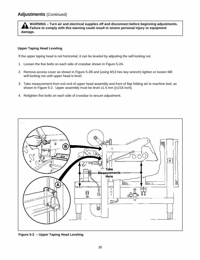
Upper Taping Head Leveling
If the upper taping head is not horizontal, it can be leveled by adjusting the self-locking nut.
1. Loosen the five bolts on each side of crossbar shown in Figure 5-2A.
2. Remove access cover as shown in Figure 5-2B and (using M13 hex key wrench) tighten or loosen M8self-locking nut until upper head is level.
3. Take measurement from exit end of upper head assembly and front of flap folding ski to machine bed, asshown in Figure 5-2. Upper assembly must be level ±1.5 mm [±1/16 inch].
4. Retighten five bolts on each side of crossbar to secure adjustment.
WARNING – Turn air and electrical supplies off and disconnect before beginning adjustments.Failure to comply with this warning could result in severe personal injury or equipment
damage.
31
Adjustments (Continued)
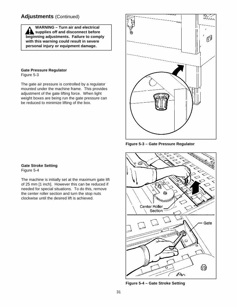
Gate Pressure RegulatorFigure 5-3
The gate air pressure is controlled by a regulatormounted under the machine frame. This providesadjustment of the gate lifting force. When lightweight boxes are being run the gate pressure canbe reduced to minimize lifting of the box.
Gate Stroke SettingFigure 5-4
The machine is initially set at the maximum gate liftof 25 mm [1 inch]. However this can be reduced ifneeded for special situations. To do this, removethe center roller section and turn the stop nutsclockwise until the desired lift is achieved.
Figure 5-3 – Gate Pressure Regulator
Figure 5-4 – Gate Stroke Setting
WARNING – Turn air and electricalsupplies off and disconnect before
beginning adjustments. Failure to complywith this warning could result in severepersonal injury or equipment damage.

32
THIS PAGE IS BLANK
33
Special Set-Up Procedure
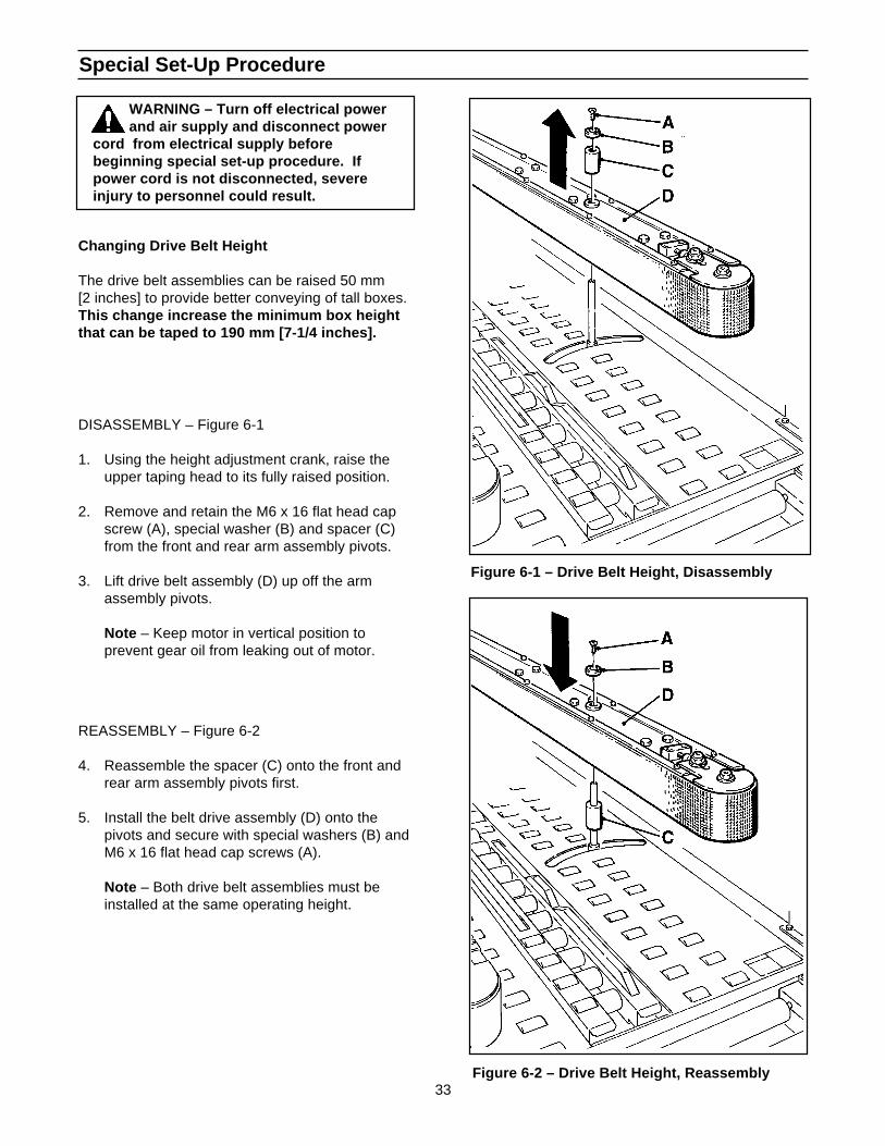
Changing Drive Belt Height
The drive belt assemblies can be raised 50 mm[2 inches] to provide better conveying of tall boxes.This change increase the minimum box heightthat can be taped to 190 mm [7-1/4 inches].
DISASSEMBLY – Figure 6-1
1. Using the height adjustment crank, raise theupper taping head to its fully raised position.
2. Remove and retain the M6 x 16 flat head capscrew (A), special washer (B) and spacer (C)from the front and rear arm assembly pivots.
3. Lift drive belt assembly (D) up off the armassembly pivots.
Note – Keep motor in vertical position toprevent gear oil from leaking out of motor.
REASSEMBLY – Figure 6-2
4. Reassemble the spacer (C) onto the front andrear arm assembly pivots first.
5. Install the belt drive assembly (D) onto thepivots and secure with special washers (B) andM6 x 16 flat head cap screws (A).
Note – Both drive belt assemblies must beinstalled at the same operating height.
Figure 6-1 – Drive Belt Height, Disassembly
Figure 6-2 – Drive Belt Height, Reassembly
WARNING – Turn off electrical powerand air supply and disconnect power
cord from electrical supply beforebeginning special set-up procedure. Ifpower cord is not disconnected, severeinjury to personnel could result.
34
Special Set-Up Procedure (Continued)
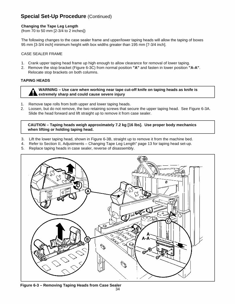
Changing the Tape Leg Length(from 70 to 50 mm [2-3/4 to 2 inches])
The following changes to the case sealer frame and upper/lower taping heads will allow the taping of boxes95 mm [3-3/4 inch] minimum height with box widths greater than 195 mm [7-3/4 inch].
CASE SEALER FRAME
1. Crank upper taping head frame up high enough to allow clearance for removal of lower taping.2. Remove the stop bracket (Figure 6-3C) from normal position "A" and fasten in lower position "A-A" .
Relocate stop brackets on both columns.
1. Remove tape rolls from both upper and lower taping heads.2. Loosen, but do not remove, the two retaining screws that secure the upper taping head. See Figure 6-3A.
Slide the head forward and lift straight up to remove it from case sealer.
TAPING HEADS
WARNING – Use care when working near tape cut-off knife on taping heads as knife isextremely sharp and could cause severe injury
3. Lift the lower taping head, shown in Figure 6-3B, straight up to remove it from the machine bed.4. Refer to Section II , Adjustments – Changing Tape Leg Length" page 13 for taping head set-up.5. Replace taping heads in case sealer, reverse of disassembly.
CAUTION – Taping heads weigh approximately 7.2 kg [16 lbs]. Use proper body mechanicswhen lifting or holding taping head.
Figure 6-3 – Removing Taping Heads from Case Sealer
35
Special Set-Up Procedure (Continued)
WARNING – It is recommended that no less than two people assist on this set-up or severeinjury or equipment damage could result.
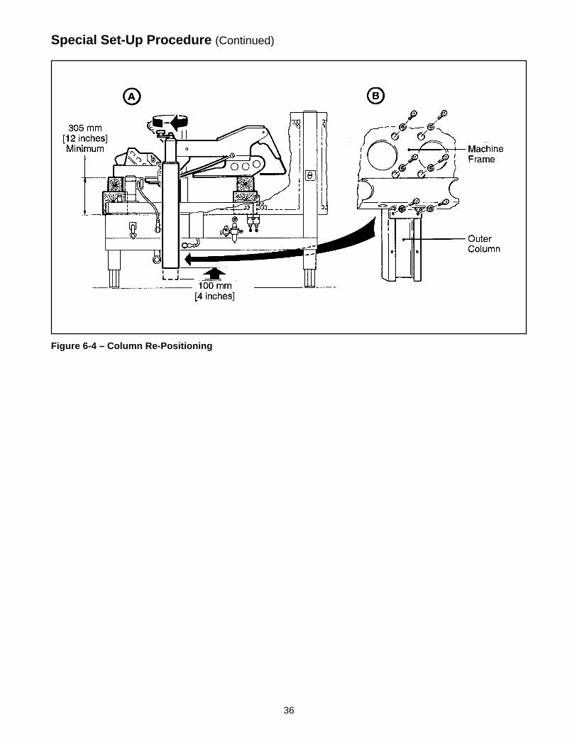
Outer Column Re-Positioning (Refer to Figure 6-4)
Moving the outer columns up one set of mounting holes increases the maximum box size handled by the casesealer from 620 mm [24-1/2 inches] to 725 mm [28-1/2 inches].
To move the outer columns up one set of mounting holes:
1. Crank side drive belts to full open position.
2. Crank upper taping head frame assembly up approximately 330 mm [13 inches] from machine bed.
3. Place solid blocks approximately 305 mm [12 inches] high beneath upper taping head frame at rear of tapinghead and under front flap folding ski (Figure 6-4A).
Note – Blocks (front and rear) must be the same height in order to keep upper frame level.
4. Crank upper taping head frame down until weight of upper frame is fully on blocks.
5. Remove and retain six mounting screws in each outer column assembly (Figure 6-4B).
6. Crank outer column up 100 mm [4 inches] and re-install six (6) screws in each column. Tighten screws.
7. Crank upper taping head up and remove blocks.
8. Check horizontal alignment of upper taping head frame and adjust as described in "Adjustments – UpperTaping Head Leveling", page 30.
WARNING – A second person should assist with this part of set-up to hold (steady) upperframe until columns are re-positioned and column screws are installed and tightened.
36
Special Set-Up Procedure (Continued)
Figure 6-4 – Column Re-Positioning
37
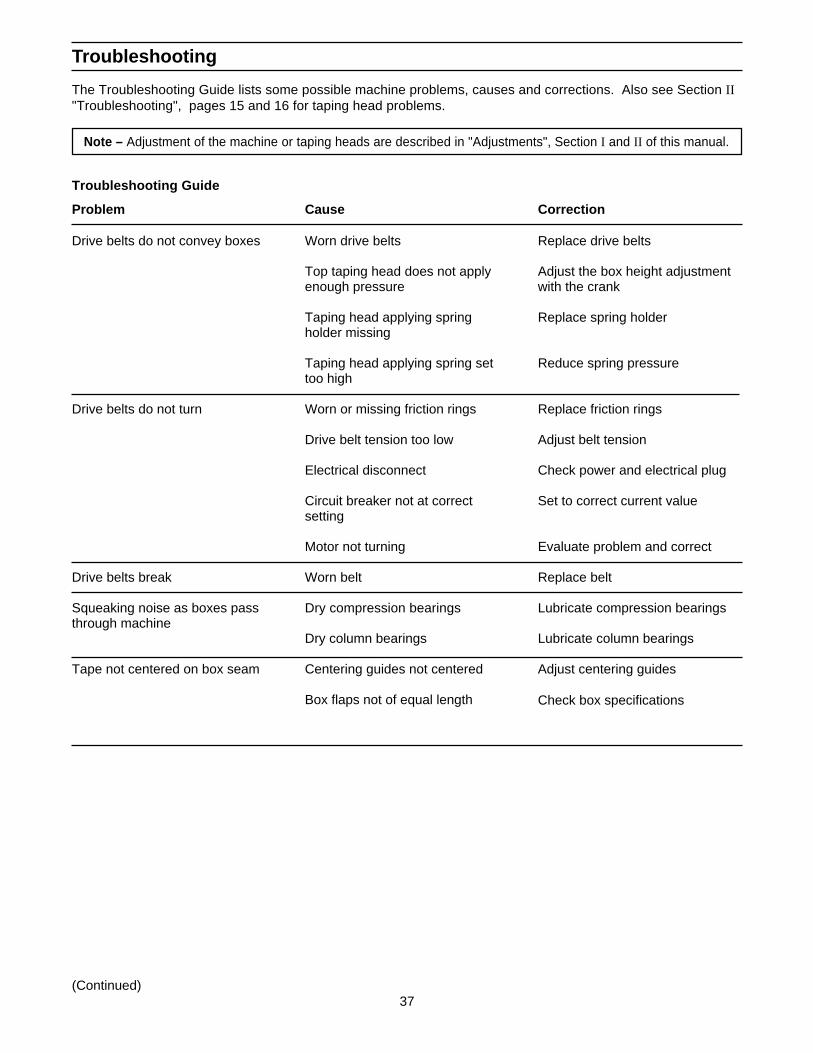
Troubleshooting
The Troubleshooting Guide lists some possible machine problems, causes and corrections. Also see Section II"Troubleshooting", pages 15 and 16 for taping head problems.
Note – Adjustment of the machine or taping heads are described in "Adjustments", Section I and II of this manual.
Problem
Drive belts do not convey boxes
Drive belts do not turn
Drive belts break
Squeaking noise as boxes passthrough machine
Tape not centered on box seam
(Continued)
Cause
Worn drive belts
Top taping head does not applyenough pressure
Taping head applying springholder missing
Taping head applying spring settoo high
Worn or missing friction rings
Drive belt tension too low
Electrical disconnect
Circuit breaker not at correctsetting
Motor not turning
Worn belt
Dry compression bearings
Dry column bearings
Centering guides not centered
Box flaps not of equal length
Correction
Replace drive belts
Adjust the box height adjustmentwith the crank
Replace spring holder
Reduce spring pressure
Replace friction rings
Adjust belt tension
Check power and electrical plug
Set to correct current value
Evaluate problem and correct
Replace belt
Lubricate compression bearings
Lubricate column bearings
Adjust centering guides
Check box specifications
Troubleshooting Guide
38
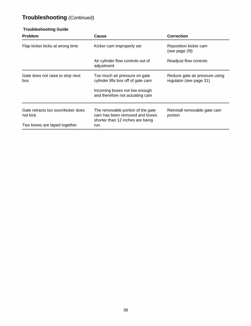
Troubleshooting (Continued)
Troubleshooting Guide
Problem
Flap kicker kicks at wrong time
Gate does not raise to stop nextbox
Gate retracts too soon/kicker doesnot kick
Two boxes are taped together
Cause
Kicker cam improperly set
Air cylinder flow controls out ofadjustment
Too much air pressure on gatecylinder lifts box off of gate cam
Incoming boxes not low enoughand therefore not actuating cam
The removable portion of the gatecam has been removed and boxesshorter than 12 inches are beingrun
Correction
Reposition kicker cam(see page 29)
Readjust flow controls
Reduce gate air pressure usingregulator (see page 31)
Reinstall removable gate camportion
39
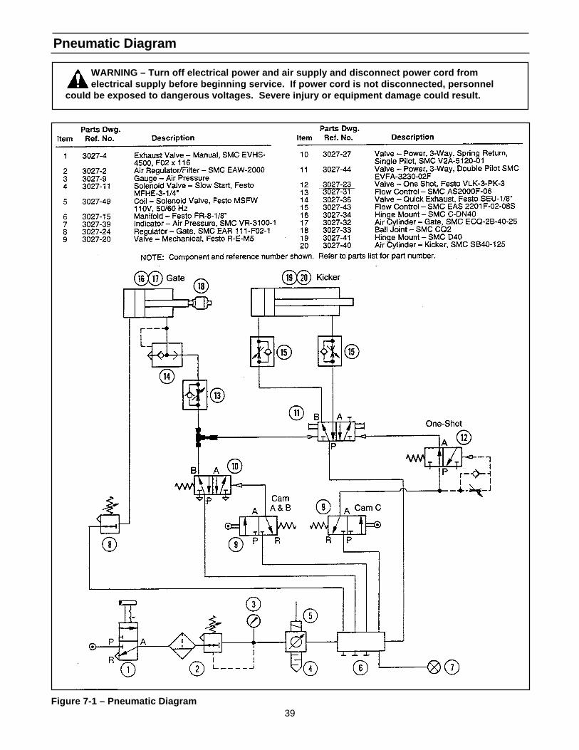
Pneumatic Diagram
Figure 7-1 – Pneumatic Diagram
WARNING – Turn off electrical power and air supply and disconnect power cord fromelectrical supply before beginning service. If power cord is not disconnected, personnel
could be exposed to dangerous voltages. Severe injury or equipment damage could result.
40
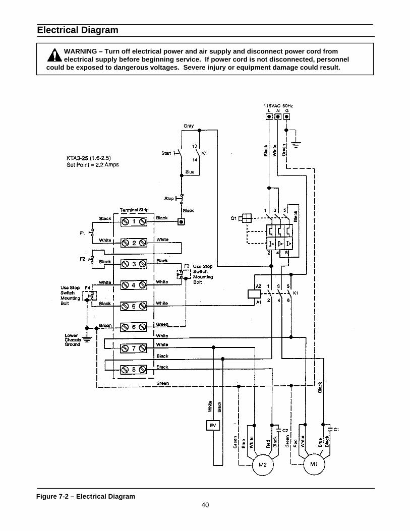
Electrical Diagram
WARNING – Turn off electrical power and air supply and disconnect power cord fromelectrical supply before beginning service. If power cord is not disconnected, personnel
could be exposed to dangerous voltages. Severe injury or equipment damage could result.
Figure 7-2 – Electrical Diagram
41

42
THIS PAGE IS BLANK
43
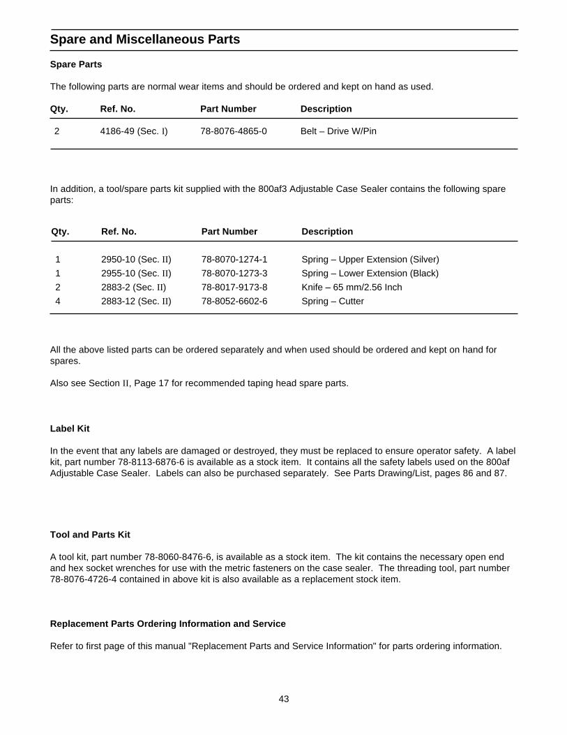
Spare and Miscellaneous Parts
Spare Parts
The following parts are normal wear items and should be ordered and kept on hand as used.
Qty. Ref. No. Part Number Description
2 4186-49 (Sec. I) 78-8076-4865-0 Belt – Drive W/Pin
Qty. Ref. No. Part Number Description
1 2950-10 (Sec. II ) 78-8070-1274-1 Spring – Upper Extension (Silver)
1 2955-10 (Sec. II ) 78-8070-1273-3 Spring – Lower Extension (Black)
2 2883-2 (Sec. II ) 78-8017-9173-8 Knife – 65 mm/2.56 Inch
4 2883-12 (Sec. II ) 78-8052-6602-6 Spring – Cutter
Tool and Parts Kit
A tool kit, part number 78-8060-8476-6, is available as a stock item. The kit contains the necessary open endand hex socket wrenches for use with the metric fasteners on the case sealer. The threading tool, part number78-8076-4726-4 contained in above kit is also available as a replacement stock item.
Replacement Parts Ordering Information and Service
Refer to first page of this manual "Replacement Parts and Service Information" for parts ordering information.
Label Kit
In the event that any labels are damaged or destroyed, they must be replaced to ensure operator safety. A labelkit, part number 78-8113-6876-6 is available as a stock item. It contains all the safety labels used on the 800afAdjustable Case Sealer. Labels can also be purchased separately. See Parts Drawing/List, pages 86 and 87.
In addition, a tool/spare parts kit supplied with the 800af3 Adjustable Case Sealer contains the following spareparts:
All the above listed parts can be ordered separately and when used should be ordered and kept on hand forspares.
Also see Section II , Page 17 for recommended taping head spare parts.
44
Options/Accessories
Part Number Option/Accessory
78-8069-3983-7 Caster Kit Attachment
78-8069-3926-6 Low Tape Sensor Kit
78-8114-0828-1 AccuGlide II STD 2 Inch Upper Taping Head, Type 39600
78-8114-0829-9 AccuGlide II STD 2 Inch Lower Taping Head, Type 39600
78-8079-5560-0 Tape Application Sensor Kit
78-8095-4854-4 2 Inch Tape Edge Fold Attachment – Top
78-8095-4855-1 2 Inch Tape Edge Fold Attachment – Bottom
For additional information on the options/accessories listed below, contact your 3M Representative.
45
Replacement Parts – Illustrations and Parts Lists800af Adjustable Case Sealer, Type 39600 (2 Inch Width Taping Heads)
Frame Assemblies
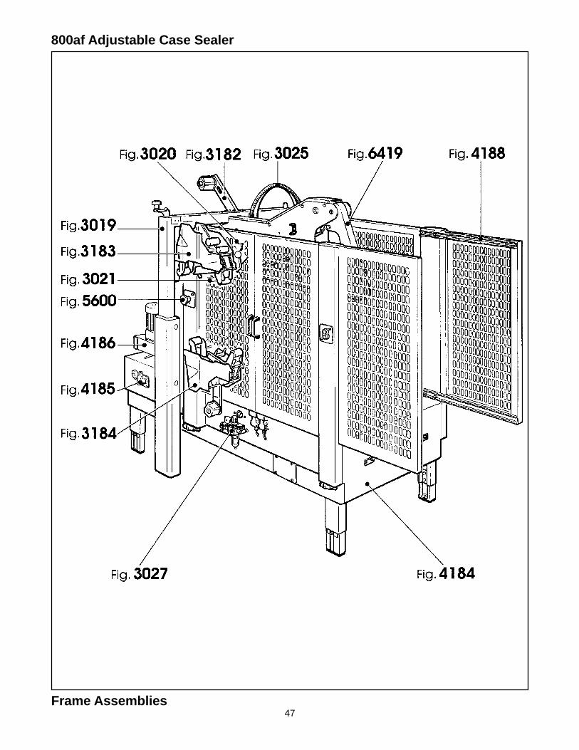
1. Refer to Frame Assemblies Figure to find all the parts illustrations identified by figure numbers.
2. Refer to the Figure or Figures to determine the individual parts required and the parts referencenumber.
3. The replacement parts list, that follows each illustration, includes the part number and part descriptionfor the parts in that illustration.
Note – The complete description has been included for standard fasteners and somecommercially available components. This has been done to allow obtaining thesestandard parts locally, should the customer elect to do so.
4. Refer to the first page of this instruction manual “Replacement Parts and Service Information” forreplacement parts ordering information.
IMPORTANT – Not all the parts listed are normally stocked items. Some parts or assem-blies shown are available only on a special order basis. Contact 3M/Tape Dispenser Partsto confirm item availability.

46
THIS PAGE IS BLANK
47
800af Adjustable Case Sealer
Frame Assemblies
48
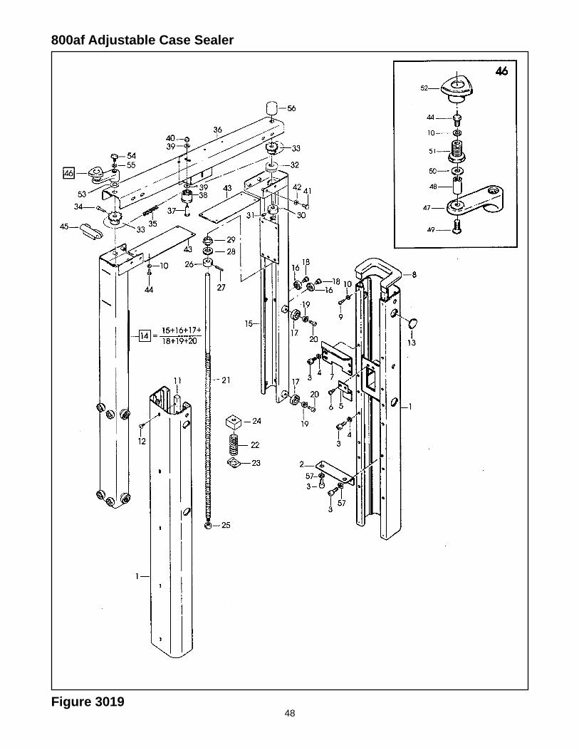
800af Adjustable Case Sealer
Figure 3019
49
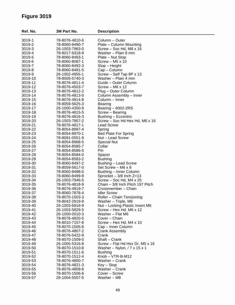
Figure 3019
Ref. No. 3M Part No. Description
3019-1 78-8076-4810-6 Column – Outer3019-2 78-8060-8490-7 Plate – Column Mounting3019-3 26-1003-7963-0 Screw – Soc Hd, M8 x 163019-4 78-8017-9318-9 Washer – Plain 8 mm3019-5 78-8060-8493-1 Plate – Nut Stop3019-6 78-8060-8087-1 Screw – M5 x 103019-7 78-8060-8492-3 Stop – Height3019-8 78-8060-8491-5 Cap – Column3019-9 26-1002-4955-1 Screw – Self Tap 8P x 133019-10 78-8005-5740-3 Washer – Plain 4 mm3019-11 78-8076-4811-4 Guide – Outer Column3019-12 78-8076-4503-7 Screw – M6 x 123019-13 78-8076-4812-2 Plug – Outer Column3019-14 78-8076-4813-0 Column Assembly – Inner3019-15 78-8076-4814-8 Column – Inner3019-16 78-8059-5625-3 Bearing3019-17 26-1000-4350-9 Bearing – 6002-2RS3019-18 78-8076-4815-5 Screw – Bearing3019-19 78-8076-4816-3 Bushing – Eccentric3019-20 26-1003-7957-2 Screw – Soc Hd Hex Hd, M6 x 163019-21 78-8076-4817-1 Lead Screw3019-22 78-8054-8997-4 Spring3019-23 78-8054-8970-1 Bed Plate For Spring3019-24 78-8091-0551-9 Nut – Lead Screw3019-25 78-8054-8968-5 Special Nut3019-26 78-8054-8585-7 Collar3019-27 78-8054-8586-5 Pin3019-28 78-8054-8584-0 Spacer3019-29 78-8054-8583-2 Bushing3019-30 78-8060-8497-2 Bushing – Lead Screw3019-31 78-8059-5617-0 Set Screw – M6 x 83019-32 78-8060-8498-0 Bushing – Inner Column3019-33 78-8060-8499-8 Sprocket – 3/8 Inch Z=133019-34 26-1003-7946-5 Screw – Soc Hd, M4 x 253019-35 78-8076-4818-9 Chain – 3/8 Inch Pitch 197 Pitch3019-36 78-8076-4819-7 Crossmember – Chain3019-37 78-8060-7878-4 Idler Screw3019-38 78-8070-1503-3 Roller – Chain Tensioning3019-39 78-8042-2919-9 Washer – Triple, M63019-40 26-1003-6916-9 Nut – Locking Plastic Insert M63019-41 26-1003-5829-5 Screw – Hex Hd. M6 x 123019-42 26-1000-0010-3 Washer – Flat M63019-43 78-8076-4820-5 Cover – Chain3019-44 78-8010-7157-8 Screw – Hex Hd, M4 x 103019-45 78-8070-1505-8 Cap – Inner Column3019-46 78-8076-4807-2 Crank Assembly3019-47 78-8076-5422-9 Crank3019-48 78-8070-1509-0 Shaft – Crank3019-49 26-1005-5316-8 Screw – Flat Hd Hex Dr, M5 x 163019-50 78-8070-1510-8 Washer – Nylon, / 7 x 15 x 13019-51 78-8070-1511-6 Bushing3019-52 78-8070-1512-4 Knob – VTR-B-M123019-53 78-8076-4800-7 Washer – Crank3019-54 78-8076-4821-3 Key – Stop3019-55 78-8076-4809-8 Washer – Crank3019-56 78-8070-1506-6 Cover – Screw3019-57 26-1004-5507-5 Washer – M8
50Figure 3020
800af Adjustable Case Sealer

51
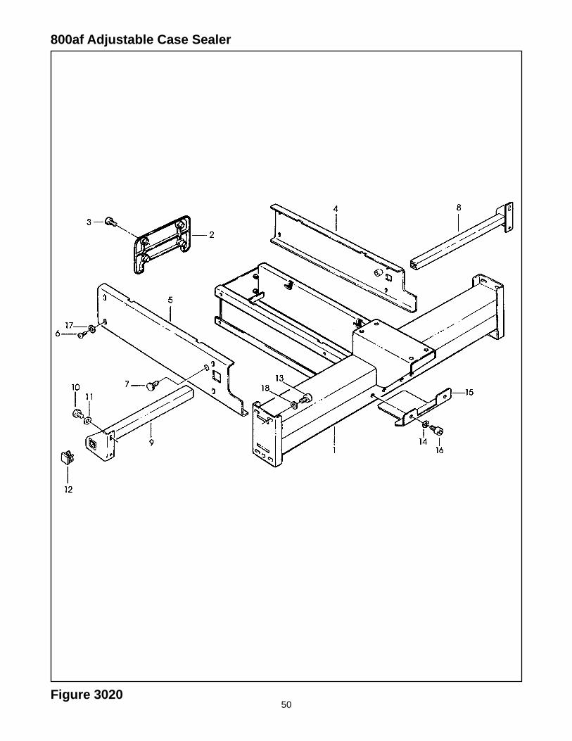
Figure 3020
Ref. No. 3M Part No. Description
3020-1 78-8076-4822-1 Support – Upper Head
3020-2 78-8076-4823-9 Cover – Rear
3020-3 26-1003-7951-5 Screw – Soc Hd Hex Soc, M5 x 20
3020-4 78-8113-6898-0 Frame Assembly – Upper, R/H (W/English Language Label)
3020-5 78-8113-6897-2 Frame Assembly – Upper, L/H (W/English Language Label)
3020-6 78-8060-8087-1 Screw – M5 x 10
3020-7 78-8070-1555-3 Block – Upper Head
3020-8 78-8076-4826-2 Support – Right Roller
3020-9 78-8076-4827-0 Support – Left Roller
3020-10 78-8032-0375-7 Screw – Hex Hd, M6 x 16
3020-11 78-8042-2919-9 Washer – Triple, M6
3020-12 78-8052-6652-1 Cap – End
3020-13 26-1003-7964-8 Screw – Soc Hd Hex Soc Dr, M8 x 20
3020-14 78-8017-9318-9 Washer – Plain 8 mm
3020-15 78-8114-4786-7 Slide
3020-16 26-1003-7963-0 Screw – Soc Hd, M8 x 16
3020-17 78-8100-1036-9 Washer
52Figure 3021
800af Adjustable Case Sealer
53
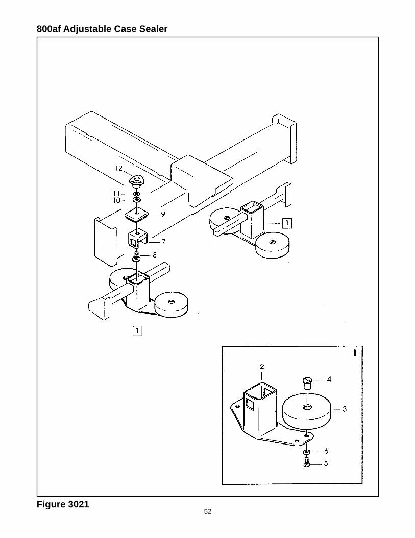
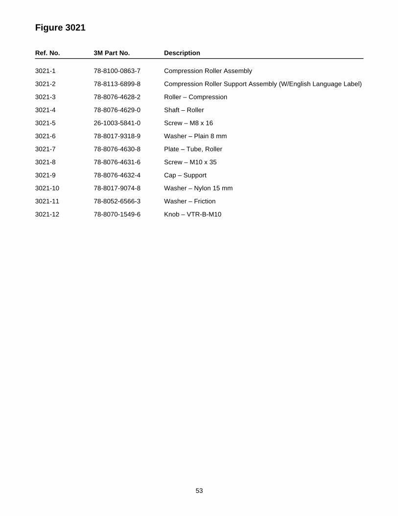
Figure 3021
Ref. No. 3M Part No. Description
3021-1 78-8100-0863-7 Compression Roller Assembly
3021-2 78-8113-6899-8 Compression Roller Support Assembly (W/English Language Label)
3021-3 78-8076-4628-2 Roller – Compression
3021-4 78-8076-4629-0 Shaft – Roller
3021-5 26-1003-5841-0 Screw – M8 x 16
3021-6 78-8017-9318-9 Washer – Plain 8 mm
3021-7 78-8076-4630-8 Plate – Tube, Roller
3021-8 78-8076-4631-6 Screw – M10 x 35
3021-9 78-8076-4632-4 Cap – Support
3021-10 78-8017-9074-8 Washer – Nylon 15 mm
3021-11 78-8052-6566-3 Washer – Friction
3021-12 78-8070-1549-6 Knob – VTR-B-M10
54
800af Adjustable Case Sealer
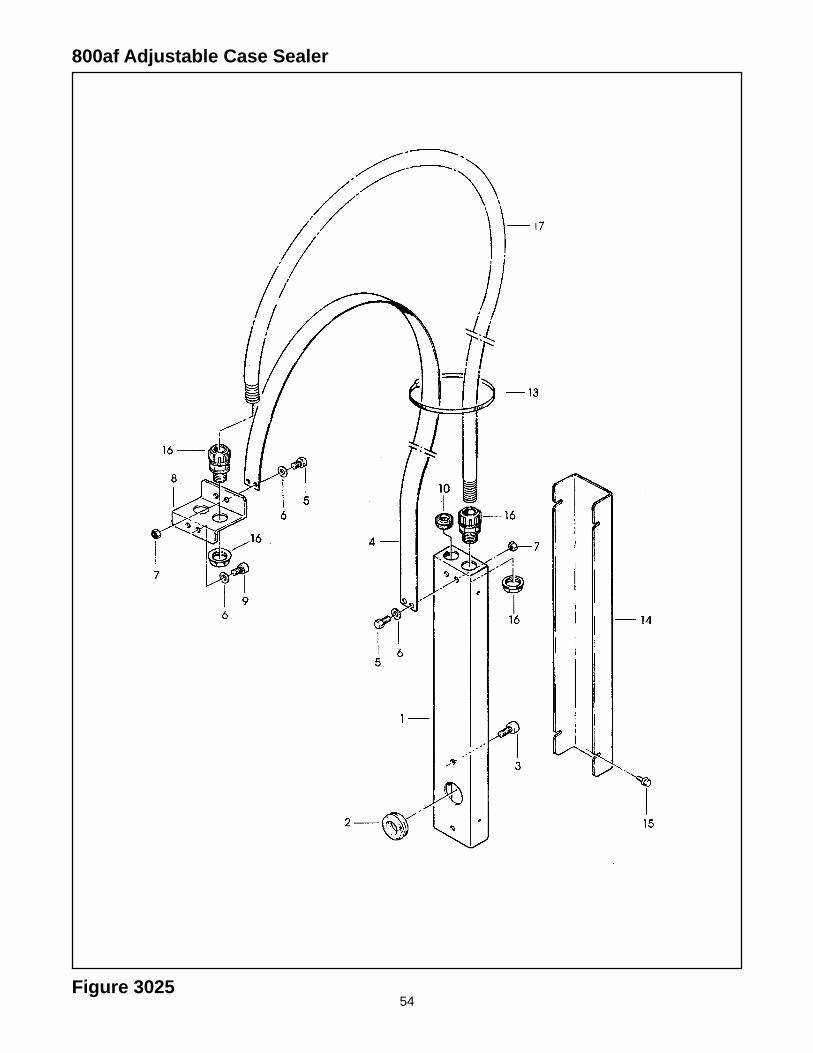
Figure 3025
55
Figure 3025
Ref. No. 3M Part No. Description
3205-1 78-8091-0660-8 Housing – Wire
3205-2 78-8076-4702-5 Grommet /28
3025-3 26-1003-7963-0 Screw – Soc Hd, M8 x 16
3025-4 78-8076-4872-6 Strap – Wire
3025-5 78-8010-7163-6 Screw – Hex Hd, M5 x 10
3025-6 78-8005-5741-1 Washer – Plain, M5
3025-7 78-8010-7417-6 Nut – Hex, M5
3025-8 78-8076-4873-4 Plate – Strap
3025-9 26-1003-7949-9 Screw – Soc Hd Hex Soc, M5 x 12
3025-10 78-8060-7758-8 Fairlead /20
3025-13 78-8060-8029-3 Clamp – 140X3,5
3025-14 78-8076-4641-5 Cover
3025-15 78-8076-4875-9 Screw – Hex Hd, M4 x 8 W/Ext.
3025-16 78-8076-4520-1 Union PG13 – Sleeve /16
3025-17 78-8076-5229-8 Sleeving – /16, 1180 mm
56
800af Adjustable Case Sealer
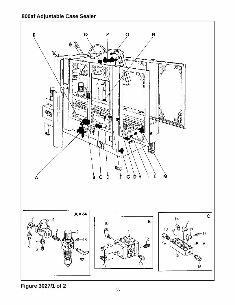
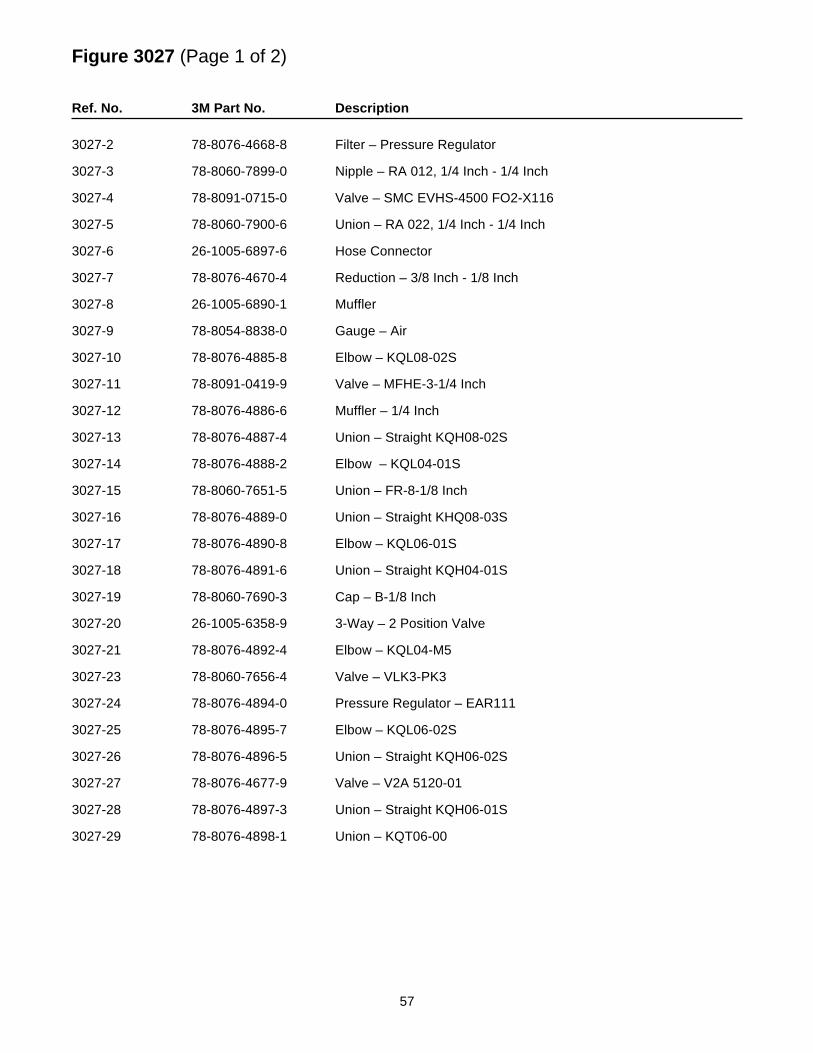
Figure 3027/1 of 2
57
Figure 3027 (Page 1 of 2)
Ref. No. 3M Part No. Description
3027-2 78-8076-4668-8 Filter – Pressure Regulator
3027-3 78-8060-7899-0 Nipple – RA 012, 1/4 Inch - 1/4 Inch
3027-4 78-8091-0715-0 Valve – SMC EVHS-4500 FO2-X116
3027-5 78-8060-7900-6 Union – RA 022, 1/4 Inch - 1/4 Inch
3027-6 26-1005-6897-6 Hose Connector
3027-7 78-8076-4670-4 Reduction – 3/8 Inch - 1/8 Inch
3027-8 26-1005-6890-1 Muffler
3027-9 78-8054-8838-0 Gauge – Air
3027-10 78-8076-4885-8 Elbow – KQL08-02S
3027-11 78-8091-0419-9 Valve – MFHE-3-1/4 Inch
3027-12 78-8076-4886-6 Muffler – 1/4 Inch
3027-13 78-8076-4887-4 Union – Straight KQH08-02S
3027-14 78-8076-4888-2 Elbow – KQL04-01S
3027-15 78-8060-7651-5 Union – FR-8-1/8 Inch
3027-16 78-8076-4889-0 Union – Straight KHQ08-03S
3027-17 78-8076-4890-8 Elbow – KQL06-01S
3027-18 78-8076-4891-6 Union – Straight KQH04-01S
3027-19 78-8060-7690-3 Cap – B-1/8 Inch
3027-20 26-1005-6358-9 3-Way – 2 Position Valve
3027-21 78-8076-4892-4 Elbow – KQL04-M5
3027-23 78-8060-7656-4 Valve – VLK3-PK3
3027-24 78-8076-4894-0 Pressure Regulator – EAR111
3027-25 78-8076-4895-7 Elbow – KQL06-02S
3027-26 78-8076-4896-5 Union – Straight KQH06-02S
3027-27 78-8076-4677-9 Valve – V2A 5120-01
3027-28 78-8076-4897-3 Union – Straight KQH06-01S
3027-29 78-8076-4898-1 Union – KQT06-00
58
800af Adjustable Case Sealer
Figure 3027/2 of 2
59
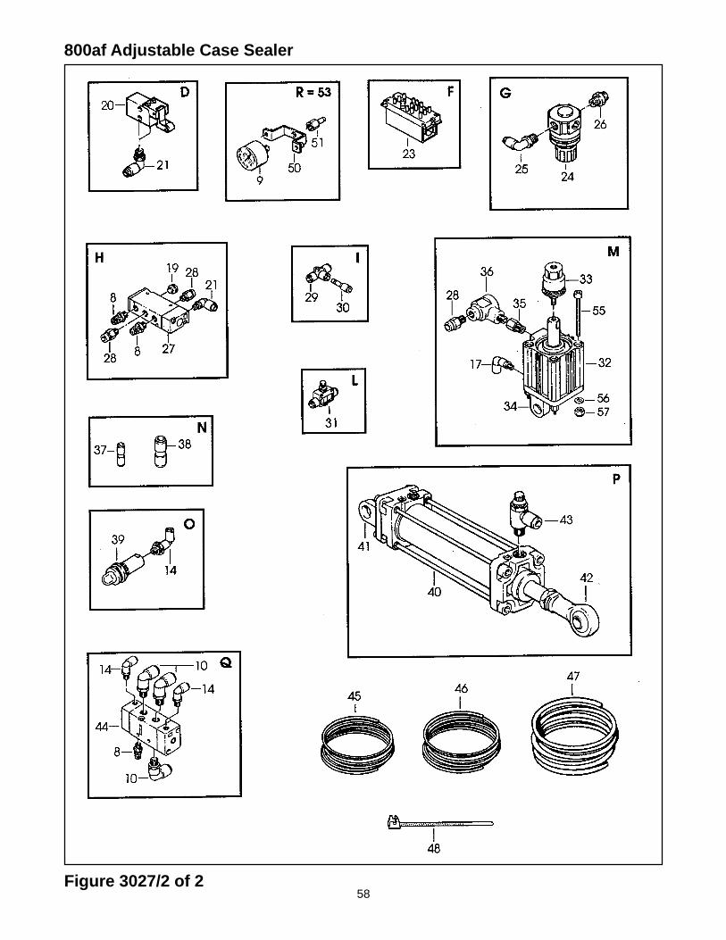
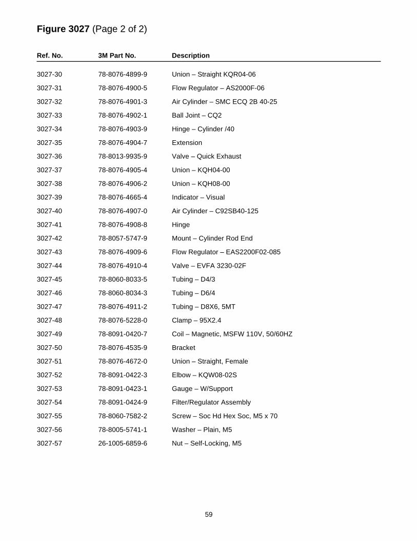
Figure 3027 (Page 2 of 2)
Ref. No. 3M Part No. Description
3027-30 78-8076-4899-9 Union – Straight KQR04-06
3027-31 78-8076-4900-5 Flow Regulator – AS2000F-06
3027-32 78-8076-4901-3 Air Cylinder – SMC ECQ 2B 40-25
3027-33 78-8076-4902-1 Ball Joint – CQ2
3027-34 78-8076-4903-9 Hinge – Cylinder /40
3027-35 78-8076-4904-7 Extension
3027-36 78-8013-9935-9 Valve – Quick Exhaust
3027-37 78-8076-4905-4 Union – KQH04-00
3027-38 78-8076-4906-2 Union – KQH08-00
3027-39 78-8076-4665-4 Indicator – Visual
3027-40 78-8076-4907-0 Air Cylinder – C92SB40-125
3027-41 78-8076-4908-8 Hinge
3027-42 78-8057-5747-9 Mount – Cylinder Rod End
3027-43 78-8076-4909-6 Flow Regulator – EAS2200F02-085
3027-44 78-8076-4910-4 Valve – EVFA 3230-02F
3027-45 78-8060-8033-5 Tubing – D4/3
3027-46 78-8060-8034-3 Tubing – D6/4
3027-47 78-8076-4911-2 Tubing – D8X6, 5MT
3027-48 78-8076-5228-0 Clamp – 95X2.4
3027-49 78-8091-0420-7 Coil – Magnetic, MSFW 110V, 50/60HZ
3027-50 78-8076-4535-9 Bracket
3027-51 78-8076-4672-0 Union – Straight, Female
3027-52 78-8091-0422-3 Elbow – KQW08-02S
3027-53 78-8091-0423-1 Gauge – W/Support
3027-54 78-8091-0424-9 Filter/Regulator Assembly
3027-55 78-8060-7582-2 Screw – Soc Hd Hex Soc, M5 x 70
3027-56 78-8005-5741-1 Washer – Plain, M5
3027-57 26-1005-6859-6 Nut – Self-Locking, M5
60
800af Adjustable Case Sealer
Figure 3182
61
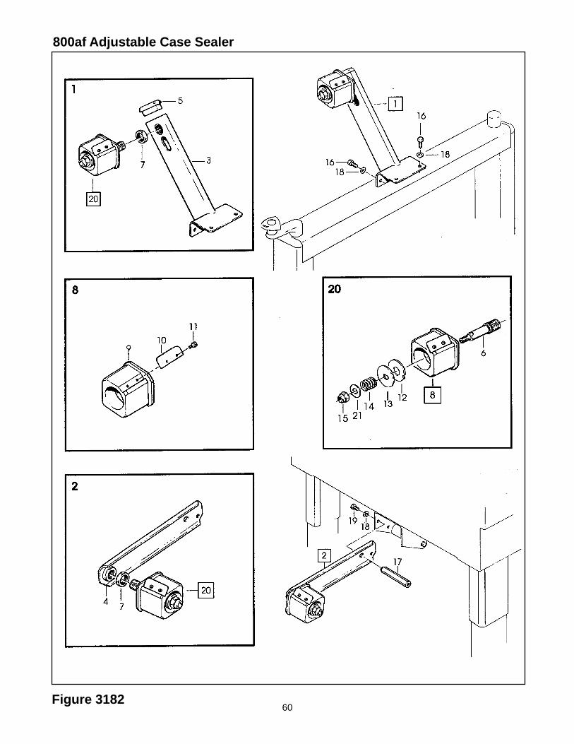
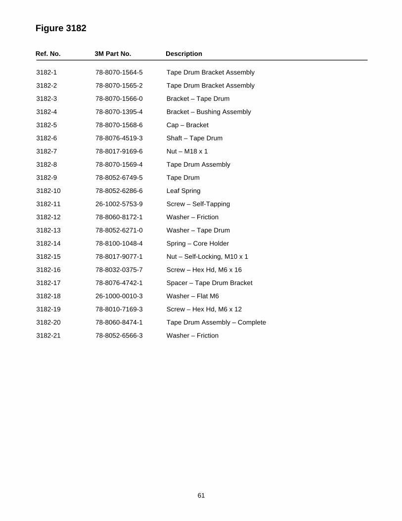
Figure 3182
Ref. No. 3M Part No. Description
3182-1 78-8070-1564-5 Tape Drum Bracket Assembly
3182-2 78-8070-1565-2 Tape Drum Bracket Assembly
3182-3 78-8070-1566-0 Bracket – Tape Drum
3182-4 78-8070-1395-4 Bracket – Bushing Assembly
3182-5 78-8070-1568-6 Cap – Bracket
3182-6 78-8076-4519-3 Shaft – Tape Drum
3182-7 78-8017-9169-6 Nut – M18 x 1
3182-8 78-8070-1569-4 Tape Drum Assembly
3182-9 78-8052-6749-5 Tape Drum
3182-10 78-8052-6286-6 Leaf Spring
3182-11 26-1002-5753-9 Screw – Self-Tapping
3182-12 78-8060-8172-1 Washer – Friction
3182-13 78-8052-6271-0 Washer – Tape Drum
3182-14 78-8100-1048-4 Spring – Core Holder
3182-15 78-8017-9077-1 Nut – Self-Locking, M10 x 1
3182-16 78-8032-0375-7 Screw – Hex Hd, M6 x 16
3182-17 78-8076-4742-1 Spacer – Tape Drum Bracket
3182-18 26-1000-0010-3 Washer – Flat M6
3182-19 78-8010-7169-3 Screw – Hex Hd, M6 x 12
3182-20 78-8060-8474-1 Tape Drum Assembly – Complete
3182-21 78-8052-6566-3 Washer – Friction
62
800af Adjustable Case Sealer
Figure 3183

63
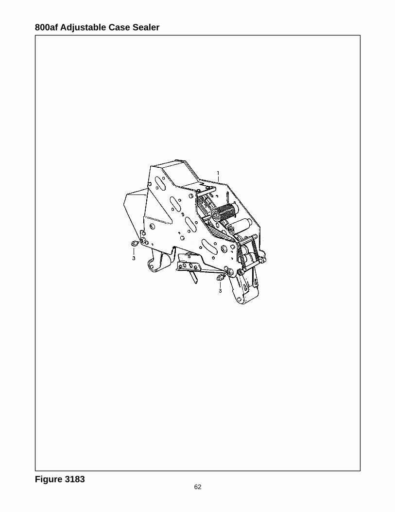
Figure 3183
Ref. No. 3M Part No. Description
3183-1 78-8114-0828-1 AccuGlide II , Upper, 2 Inch – Type 39600
3183-3 78-8076-4991-4 Spacer
Note – See Section II of this manual for taping head parts.
64
800af Adjustable Case Sealer
Figure 3184

65
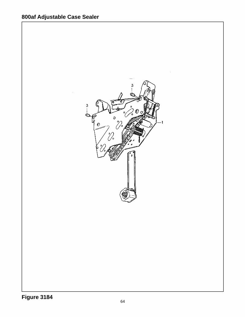
Figure 3184
Ref. No. 3M Part No. Description
3184-1 78-8114-0829-9 AccuGlide II, Lower, 2 Inch – Type 39600
3184-3 78-8060-8460-0 Stud – 2 Inch Bottom Hd Mount
Note – See Section II of this manual for taping head parts.
66
800af Adjustable Case Sealer
Figure 4184/1 of 4
67
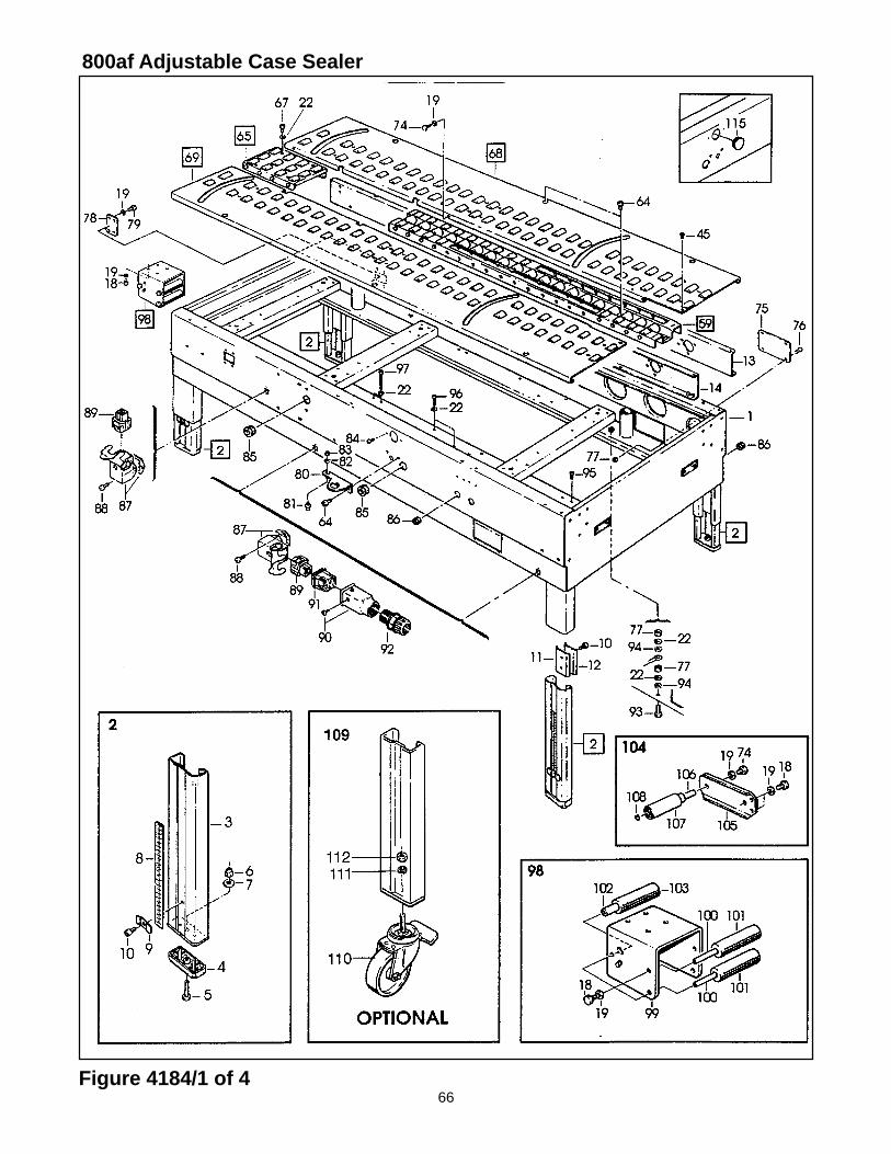
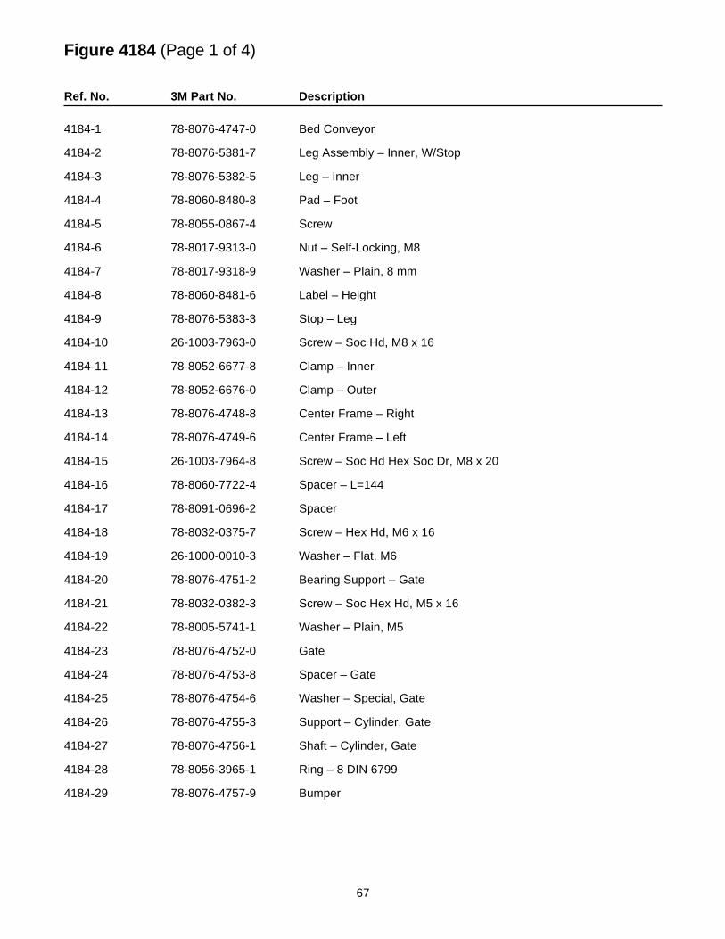
Figure 4184 (Page 1 of 4)
Ref. No. 3M Part No. Description
4184-1 78-8076-4747-0 Bed Conveyor
4184-2 78-8076-5381-7 Leg Assembly – Inner, W/Stop
4184-3 78-8076-5382-5 Leg – Inner
4184-4 78-8060-8480-8 Pad – Foot
4184-5 78-8055-0867-4 Screw
4184-6 78-8017-9313-0 Nut – Self-Locking, M8
4184-7 78-8017-9318-9 Washer – Plain, 8 mm
4184-8 78-8060-8481-6 Label – Height
4184-9 78-8076-5383-3 Stop – Leg
4184-10 26-1003-7963-0 Screw – Soc Hd, M8 x 16
4184-11 78-8052-6677-8 Clamp – Inner
4184-12 78-8052-6676-0 Clamp – Outer
4184-13 78-8076-4748-8 Center Frame – Right
4184-14 78-8076-4749-6 Center Frame – Left
4184-15 26-1003-7964-8 Screw – Soc Hd Hex Soc Dr, M8 x 20
4184-16 78-8060-7722-4 Spacer – L=144
4184-17 78-8091-0696-2 Spacer
4184-18 78-8032-0375-7 Screw – Hex Hd, M6 x 16
4184-19 26-1000-0010-3 Washer – Flat, M6
4184-20 78-8076-4751-2 Bearing Support – Gate
4184-21 78-8032-0382-3 Screw – Soc Hex Hd, M5 x 16
4184-22 78-8005-5741-1 Washer – Plain, M5
4184-23 78-8076-4752-0 Gate
4184-24 78-8076-4753-8 Spacer – Gate
4184-25 78-8076-4754-6 Washer – Special, Gate
4184-26 78-8076-4755-3 Support – Cylinder, Gate
4184-27 78-8076-4756-1 Shaft – Cylinder, Gate
4184-28 78-8056-3965-1 Ring – 8 DIN 6799
4184-29 78-8076-4757-9 Bumper
68Figure 4184/2 of 4
800af Adjustable Case Sealer
69
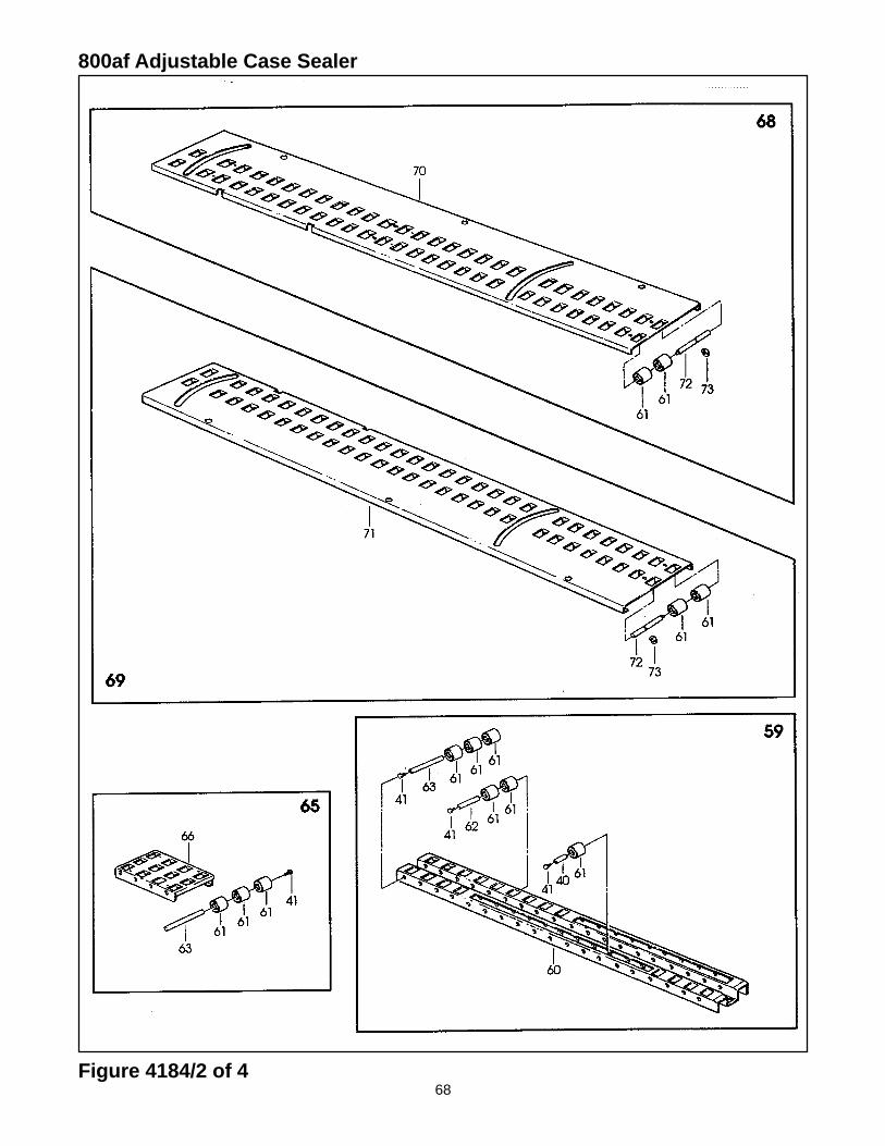
Figure 4184 (Page 2 of 4)
Ref. No. 3M Part No. Description
4184-30 78-8076-4772-8 Support Assembly W/Cam – Gate
4184-31 78-8076-4773-6 Support Assembly – Cam, Gate
4184-32 26-1003-7947-3 Screw – Soc Hd Hex Soc, M4 x 35
4184-33 78-8054-8758-0 Spacer – Valve Holder
4184-34 78-8059-5607-1 Plate – Threaded
4184-35 78-8054-8757-2 Pin – Spring Holder
4184-36 26-1005-6859-6 Nut – Self-Locking, M5
4184-37 78-8076-4774-4 Spring
4184-38 78-8055-0746-0 Link – Front Actuator, 12AF Black
4184-39 78-8055-0747-8 Link – Rear Actuator, 12AF Black
4184-40 78-8054-8857-0 Shaft – 8 x 43 mm
4184-41 78-8010-7163-6 Screw –– Hex Hd, M5 x 10
4184-42 26-1002-4955-1 Screw – Self-Tap, 8P x 13
4184-43 78-8076-4775-1 Support Assembly– Cam
4184-44 78-8054-8858-8 Spacer – 8 x 26,5 mm
4184-45 26-1002-3866-1 Screw – Flat Hd Hx Dr, M5 x 10
4184-46 78-8076-4776-9 Cam – Long
4184-47 78-8076-4777-7 Cam – Short
4184-48 26-1003-7953-1 Screw – Soc Hd, M5 x 30
4184-49 78-8023-2334-1 Screw – Soc Hd, Hex Soc, M6 x 25
4184-50 78-8076-4778-5 Actuator Assembly
4184-51 78-8076-4779-3 Support – Actuator
4184-52 26-1003-6914-4 Nut – Plastic Insert, M4
4184-53 78-8005-5740-3 Washer – Plain, 4 mm
4184-54 78-8076-4780-1 Guide – Right, Actuator
4184-55 78-8076-4781-9 Guide – Left, Actuator
4184-56 78-8076-4782-7 Actuator – Flap Folder
4184-57 78-8076-4784-3 Screw – Soc Hd Hex Hd, M6 x 35
70Figure 4184/3 of 4
800af Adjustable Case Sealer
71
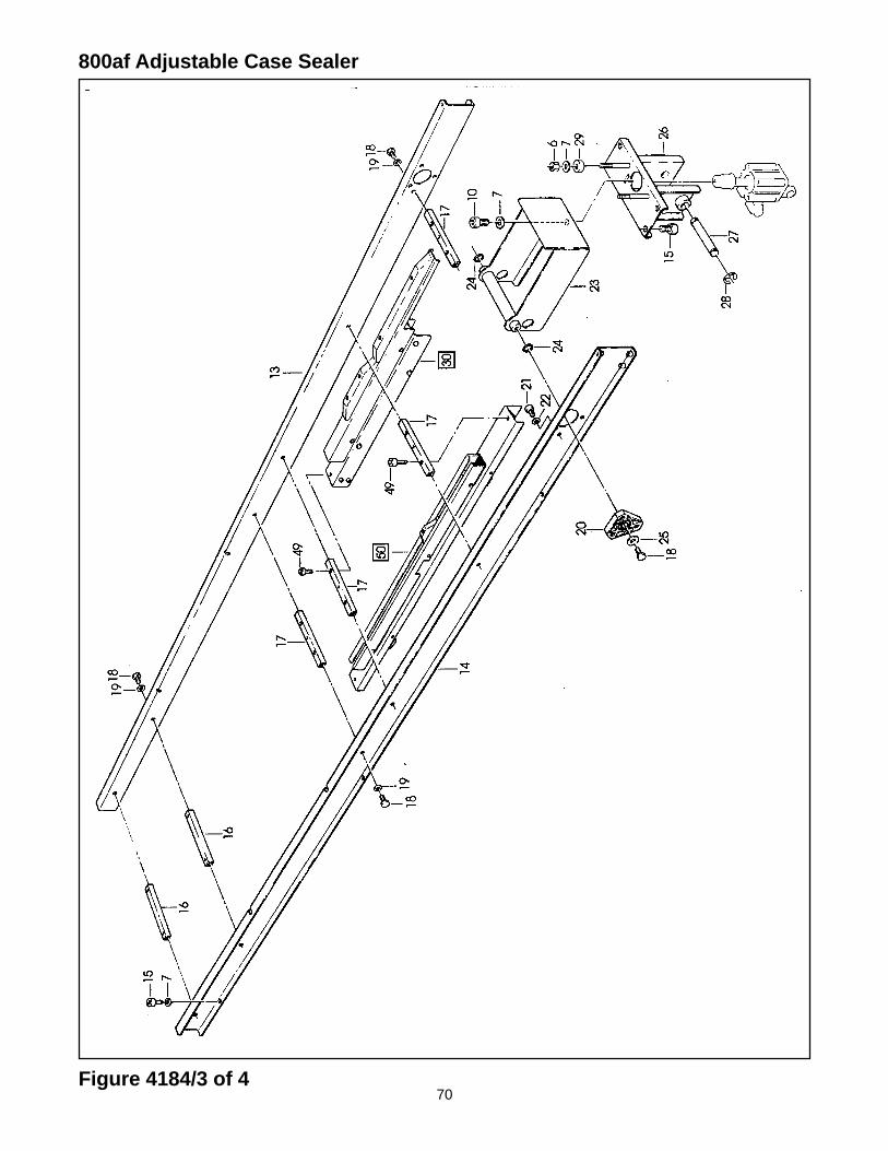
Figure 4184 (Page 3 of 4)
Ref. No. 3M Part No. Description
4184-58 78-8076-4783-5 Plate – Actuator
4184-59 78-8076-4764-5 Conveyor Assembly – Center
4184-60 78-8091-0356-3 Conveyor – Center
4184-61 78-8060-7693-7 Roller – 32 x 38
4184-62 78-8076-4766-0 Shaft – /8 x 83
4184-63 78-8052-6694-3 Shaft – /8 x 128
4184-64 78-8010-7209-7 Screw – Soc Hd, M6 x 12
4184-65 78-8076-4762-9 Conveyor Assembly – Rear
4184-66 78-8076-4763-7 Conveyor – Rear
4184-67 26-1003-7948-1 Screw – Soc Hd Hex Soc, M5 x 10
4184-68 78-8076-4767-8 Conveyor Assembly – Right
4184-69 78-8076-4768-6 Conveyor Assembly – Left
4184-70 78-8113-6901-2 R/H Conveyor Label Assembly (W/English Language Label)
4184-71 78-8113-6902-0 L/H Conveyor Label Assembly (W/English Language Label)
4184-72 78-8076-4771-0 Shaft – Roller
4184-73 78-8060-8035-0 E-Ring – 7DIN6799
4184-74 78-8010-7169-3 Screw – Hex Hd, M6 x 12
4184-75 78-8060-8487-3 Cover – Switch
4184-76 78-8060-8087-1 Screw – M5 x 10
4184-77 78-8010-7417-6 Nut – Hex, M5
4184-78 78-8076-4761-1 Plate
4184-79 26-1003-5829-5 Screw – Hex Hd, M6 x 12
4184-80 78-8091-0612-9 Plate – L/H
4184-81 78-8091-0613-7 Shaft – Valve
4184-82 78-8042-2919-9 Washer – Triple, M6
4184-83 26-1003-6916-9 Nut – Locking Plastic Insert, M6
4184-84 78-8076-4625-8 Screw – Special, M5 x 16
4184-85 78-8076-4702-5 Grommet – /28
4184-86 78-8060-7758-8 Fairlead /20
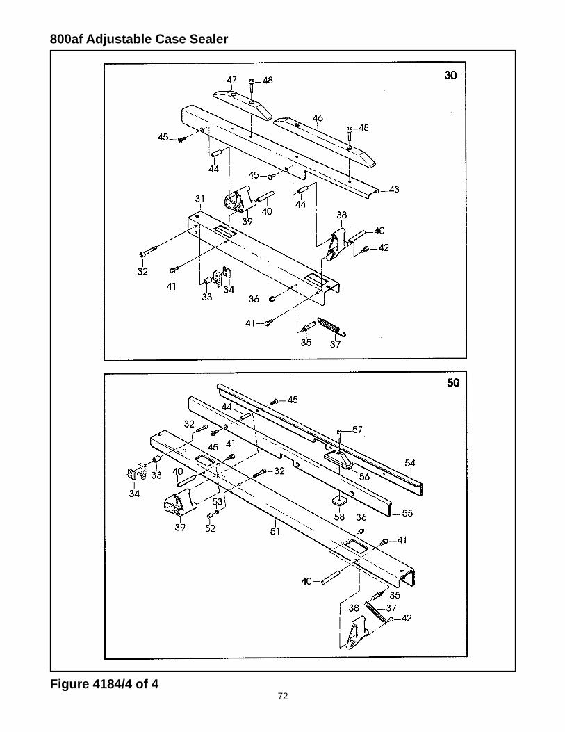
72Figure 4184/4 of 4
800af Adjustable Case Sealer
73
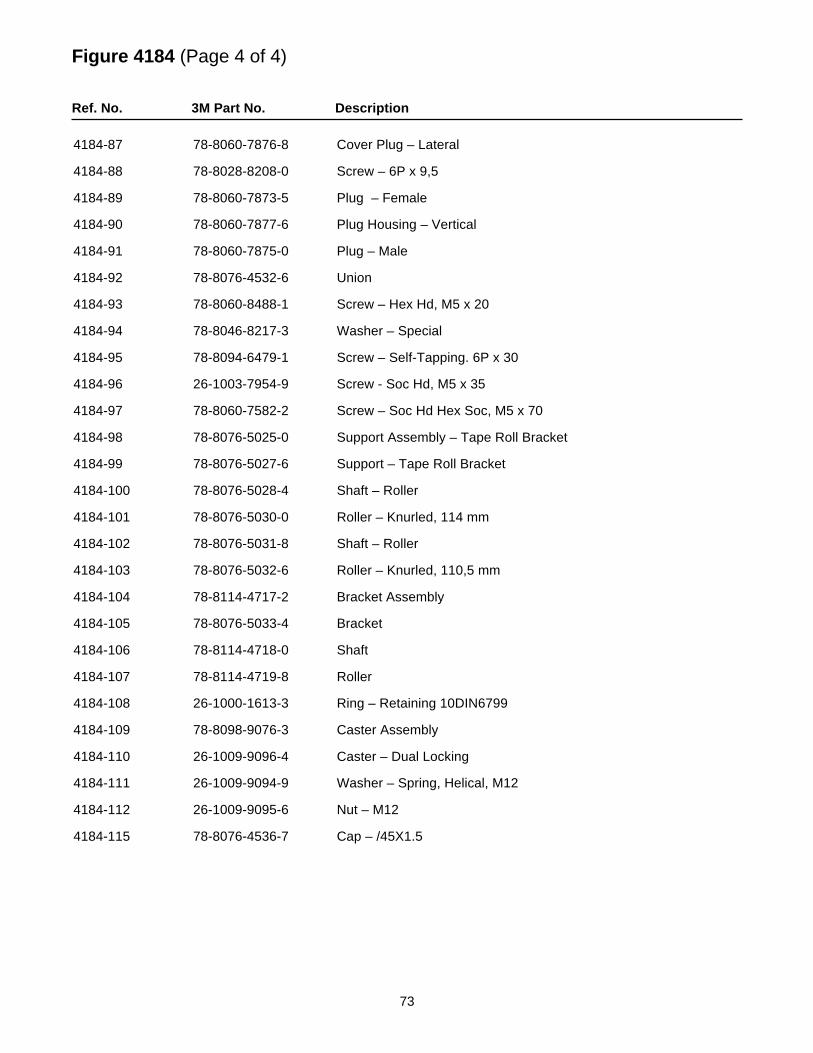
Figure 4184 (Page 4 of 4)
Ref. No. 3M Part No. Description
4184-87 78-8060-7876-8 Cover Plug – Lateral
4184-88 78-8028-8208-0 Screw – 6P x 9,5
4184-89 78-8060-7873-5 Plug – Female
4184-90 78-8060-7877-6 Plug Housing – Vertical
4184-91 78-8060-7875-0 Plug – Male
4184-92 78-8076-4532-6 Union
4184-93 78-8060-8488-1 Screw – Hex Hd, M5 x 20
4184-94 78-8046-8217-3 Washer – Special
4184-95 78-8094-6479-1 Screw – Self-Tapping. 6P x 30
4184-96 26-1003-7954-9 Screw - Soc Hd, M5 x 35
4184-97 78-8060-7582-2 Screw – Soc Hd Hex Soc, M5 x 70
4184-98 78-8076-5025-0 Support Assembly – Tape Roll Bracket
4184-99 78-8076-5027-6 Support – Tape Roll Bracket
4184-100 78-8076-5028-4 Shaft – Roller
4184-101 78-8076-5030-0 Roller – Knurled, 114 mm
4184-102 78-8076-5031-8 Shaft – Roller
4184-103 78-8076-5032-6 Roller – Knurled, 110,5 mm
4184-104 78-8114-4717-2 Bracket Assembly
4184-105 78-8076-5033-4 Bracket
4184-106 78-8114-4718-0 Shaft
4184-107 78-8114-4719-8 Roller
4184-108 26-1000-1613-3 Ring – Retaining 10DIN6799
4184-109 78-8098-9076-3 Caster Assembly
4184-110 26-1009-9096-4 Caster – Dual Locking
4184-111 26-1009-9094-9 Washer – Spring, Helical, M12
4184-112 26-1009-9095-6 Nut – M12
4184-115 78-8076-4536-7 Cap – /45X1.5
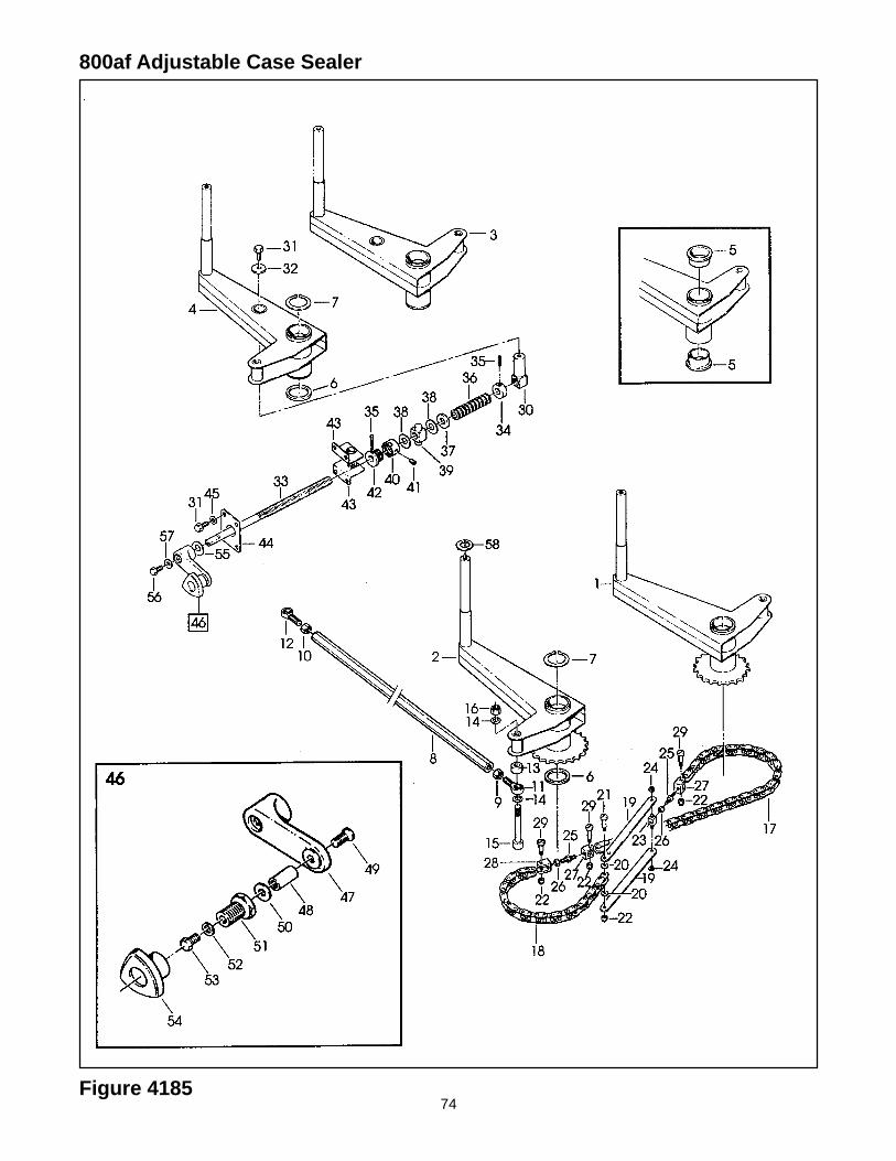
74Figure 4185
800af Adjustable Case Sealer
75
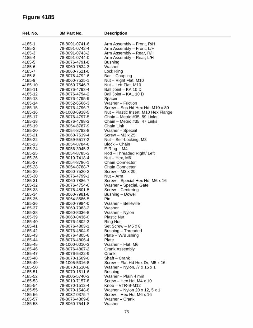
Figure 4185
Ref. No. 3M Part No. Description
4185-1 78-8091-0741-6 Arm Assembly – Front, R/H4185-2 78-8091-0742-4 Arm Assembly – Front, L/H4185-3 78-8091-0743-2 Arm Assembly – Rear, R/H4185-4 78-8091-0744-0 Arm Assembly – Rear, L/H4185-5 78-8076-4791-8 Bushing4185-6 78-8060-7534-3 Washer4185-7 78-8060-7521-0 Lock Ring4185-8 78-8076-4792-6 Bar – Coupling4185-9 78-8060-7525-1 Nut – Right Flat, M104185-10 78-8060-7546-7 Nut – Left Flat, M104185-11 78-8076-4793-4 Ball Joint – KA 10 D4185-12 78-8076-4794-2 Ball Joint – KAL 10 D4185-13 78-8076-4795-9 Spacer4185-14 78-8052-6566-3 Washer – Friction4185-15 78-8076-4796-7 Screw – Soc Hd Hex Hd, M10 x 804185-16 26-1003-6918-5 Nut – Plastic Insert, M10 Hex Flange4185-17 78-8076-4797-5 Chain – Metric #35, 59 Links4185-18 78-8076-4798-3 Chain – Metric #35, 47 Links4185-19 78-8054-8787-9 Chain Link4185-20 78-8054-8783-8 Washer – Special4185-21 78-8060-7519-4 Screw – M3 x 254185-22 78-8059-5517-2 Nut – Self-Locking, M34185-23 78-8054-8784-6 Block – Chain4185-24 78-8056-3945-3 E-Ring – M44185-25 78-8054-8785-3 Rod – Threaded Right/ Left4185-26 78-8010-7418-4 Nut – Hex, M64185-27 78-8054-8786-1 Chain Connector4185-28 78-8054-8788-7 Chain Connector4185-29 78-8060-7520-2 Screw – M3 x 204185-30 78-8076-4799-1 Nut – Arm4185-31 78-8060-7886-7 Screw – Special Hex Hd, M6 x 164185-32 78-8076-4754-6 Washer – Special, Gate4185-33 78-8076-4801-5 Screw – Centering4185-34 78-8060-7981-6 Bushing – Dowel4185-35 78-8054-8586-5 Pin4185-36 78-8060-7984-0 Washer – Belleville4185-37 78-8060-7983-2 Washer4185-38 78-8060-8036-8 Washer – Nylon4185-39 78-8060-8436-0 Plastic Nut4185-40 78-8076-4802-3 Ring Nut4185-41 78-8076-4803-1 Set Screw – M5 x 84185-42 78-8076-4804-9 Bushing – Threaded4185-43 78-8076-4805-6 Plate – W/Bushing4185-44 78-8076-4806-4 Plate4185-45 26-1000-0010-3 Washer – Flat, M64185-46 78-8076-4807-2 Crank Assembly4185-47 78-8076-5422-9 Crank4185-48 78-8070-1509-0 Shaft – Crank4185-49 26-1005-5316-8 Screw – Flat Hd Hex Dr, M5 x 164185-50 78-8070-1510-8 Washer – Nylon, /7 x 15 x 14185-51 78-8070-1511-6 Bushing4185-52 78-8005-5740-3 Washer – Plain 4 mm4185-53 78-8010-7157-8 Screw – Hex Hd, M4 x 104185-54 78-8070-1512-4 Knob – VTR-B-M124185-55 78-8070-1548-8 Washer – Nylon 20 x 12, 5 x 14185-56 78-8032-0375-7 Screw – Hex Hd, M6 x 164185-57 78-8076-4809-8 Washer – Crank4185-58 78-8060-7541-8 Washer
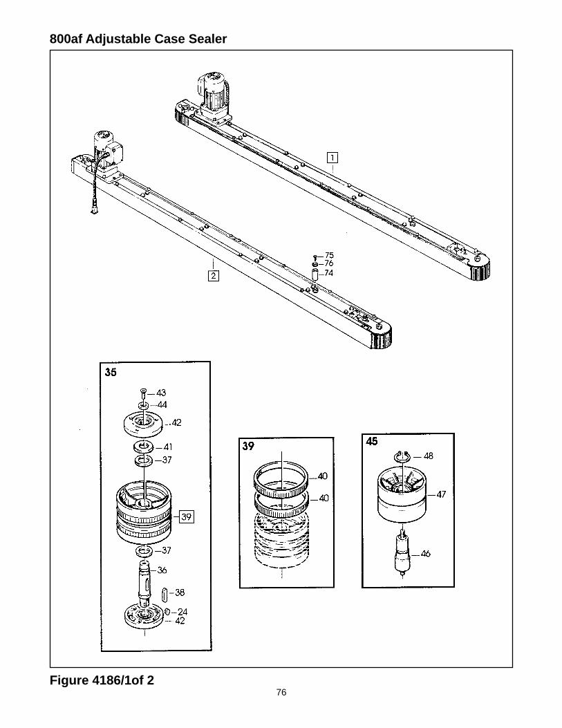
76
800af Adjustable Case Sealer
Figure 4186/1of 2
77
Figure 4186 (Page 1 of 2)
Ref. No. 3M Part No. Description
4186-1 78-8091-0745-7 Side Drive Assembly – R/H, W/O Motor
78-8098-8956-7 Side Drive Assembly – R/H, With Motor
4186-2 78-8091-0746-5 Side Drive Assembly – L/H, W/O Motor
78-8098-8957-5 Side Drive Assembly – L/H, With Motor
4186-3 78-8091-0747-3 Guide – Lower, R/H
4186-4 78-8091-0748-1 Guide – Lower, L/H
4186-5 78-8091-0749-9 Guide – Upper, R/H
4186-6 78-8091-0750-7 Guide – Upper, L/H
4186-7 78-8091-0500-6 Bushing – Side Drive
4186-8 78-8060-7995-6 Pin – Roller
4186-9 78-8060-7996-4 Roller
4186-10 78-8091-0751-5 Plate – Roller Stop, Right
4186-11 78-8091-0752-3 Plate – Roller Stop, Left
4186-12 78-8091-0753-1 Plate – Roller Stop, Right, R/H Drive
4186-13 78-8091-0754-9 Plate – Roller Stop, Left, R/H Drive
4186-14 78-8091-0755-6 Plate – Roller Stop, Right, L/H Drive
4186-15 78-8091-0756-4 Plate – Roller Stop, Left, L/H Drive
4186-16 78-8076-5255-3 Screw – Phillips Hd, M4 x 12
4186-17 78-8005-5740-3 Washer – Plain, 4 mm
4186-18 78-8076-4855-1 Washer – Special
4186-19 78-8054-8910-7 Spacer – Hexagonal
4186-20 26-1003-5829-5 Screw – Hex Hd, M6 x 12
4186-21 26-1000-0010-3 Washer – Flat, M6
4186-22 78-8076-5439-3 Flange Assembly
4186-23 78-8091-0757-2 Extension – Gearmotor
4186-24 78-8046-8135-7 Key – 5 x 5, 12 mm
4186-25 78-8091-0758-0 Sprocket – 3/8 Inch, Z=14
4186-26 78-8057-5834-5 Tab Washer
4186-27 78-8057-5835-2 Centering Washer
4186-28 78-8091-0759-8 Sprocket – 3/8 Inch, Z=23
4186-29 78-8076-4933-6 Chain – 3/8 Inch Pitch, 52 Pitch
4186-30 78-8094-6109-4 Support – Gearmotor
4186-31 78-8010-7210-5 Screw – Soc Hd Hex Soc, M6 x 20
4186-32 78-8070-1522-3 Gearmotor – 115V, 60HZ, Bodine 42R5BFC1-E2
4186-33 78-8070-1523-1 Screw – 1/4-28 x 1/2 SHCS
4186-34 26-1011-8828-7 Capacitor – 115V Gearmotor
4186-35 78-8076-4862-7 Pulley – Drive
4186-36 78-8054-8878-6 Shaft – Pulley Keyed
4186-37 78-8054-8879-4 Washer – /20,5 mm
4186-38 78-8057-5739-6 Key – M5 x 5 x 30 mm
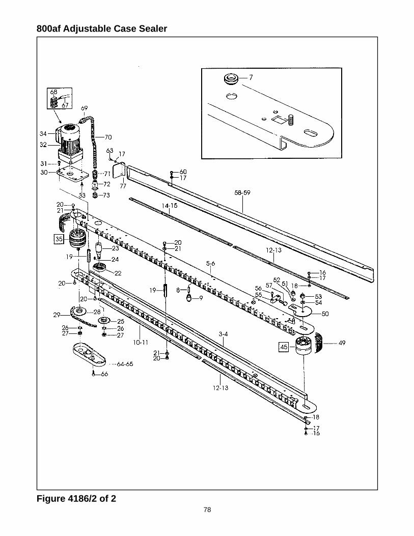
78
800af Adjustable Case Sealer
Figure 4186/2 of 2
79
Figure 4186 (Page 2 of 2)
Ref. No. 3M Part No. Description
4186-39 78-8076-5105-0 Pulley Assembly – Drive
4186-40 78-8052-6713-1 Ring – Polyurethane
4186-41 78-8017-9096-1 Nut – Special, M18 x 1
4186-42 78-8076-5442-7 Flange Assembly
4186-43 26-0001-5862-1 Screw – Flat Hd Soc, M5 x 12
4186-44 78-8054-8877-8 Washer – 5.5/20 x 4
4186-45 78-8060-8014-5 Idler Roller Assembly
4186-46 78-8054-8913-1 Shaft – Roller
4186-47 78-8052-6710-7 Roller – Idler
4186-48 12-7997-0272-0 E-Ring – M-25
4186-49 78-8076-4865-0 Belt – Box Drive
4186-50 78-8091-0761-4 Plate – Belt Tensioning
4186-51 26-1003-6918-5 Nut – Plastic Insert, M10 Hex Flange
4186-52 78-8052-6566-3 Washer – Friction
4186-53 26-1000-1347-8 Nut – Hex, M8
4186-54 78-8017-9318-9 Washer – Plain, 8 mm
4186-55 78-8054-8903-2 Block – Belt
4186-56 78-8010-7210-5 Screw – Soc Hd Hex Soc, M6 x 20
4186-57 78-8054-8904-0 Screw – Belt Adjustment
4186-58 78-8091-0762-2 Cover – Drive, Right
4186-59 78-8091-0763-0 Cover – Drive, Left
4186-60 26-1002-5753-9 Screw – Self-Tapping
4186-63 26-1002-4955-1 Screw – Self-Tap, 8P x 13
4186-64 78-8091-0764-8 Cover – Chain, Right
4186-65 78-8091-0765-5 Cover – Chain, Left
4186-66 78-8010-7165-1 Screw – Flat Hd Soc, M5 x 25
4186-67 78-8060-8053-3 Wire – 3-Pole, 5 Meters Length
4186-68 78-8076-4968-2 Terminal
4186-69 78-8060-7631-7 Connector – 3/8 Inch
4186-70 78-8076-4871-8 Sleeving – /12, 600 mm
4186-71 78-8060-7626-7 Connector – PG 11/12
4186-72 78-8060-7877-6 Plug – Housing Vertical
4186-73 78-8060-7875-0 Plug – Male
4186-74 78-8091-0766-3 Spacer – Drive
4186-75 26-1001-9843-6 Screw – Flat Soc Hd, M6 x 16
4186-76 78-8054-8577-4 Washer – Special
4186-77 78-8114-4787-5 Guard – Belt
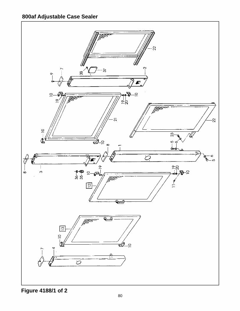
80
800af Adjustable Case Sealer
Figure 4188/1 of 2
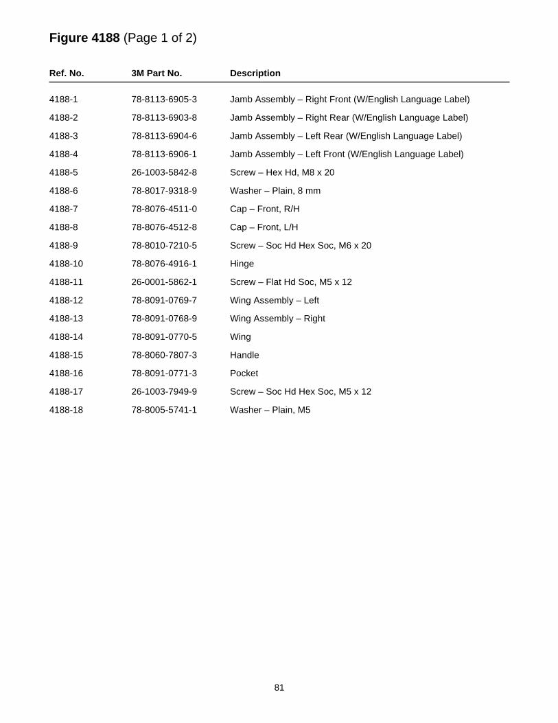
81
Figure 4188 (Page 1 of 2)
Ref. No. 3M Part No. Description
4188-1 78-8113-6905-3 Jamb Assembly – Right Front (W/English Language Label)
4188-2 78-8113-6903-8 Jamb Assembly – Right Rear (W/English Language Label)
4188-3 78-8113-6904-6 Jamb Assembly – Left Rear (W/English Language Label)
4188-4 78-8113-6906-1 Jamb Assembly – Left Front (W/English Language Label)
4188-5 26-1003-5842-8 Screw – Hex Hd, M8 x 20
4188-6 78-8017-9318-9 Washer – Plain, 8 mm
4188-7 78-8076-4511-0 Cap – Front, R/H
4188-8 78-8076-4512-8 Cap – Front, L/H
4188-9 78-8010-7210-5 Screw – Soc Hd Hex Soc, M6 x 20
4188-10 78-8076-4916-1 Hinge
4188-11 26-0001-5862-1 Screw – Flat Hd Soc, M5 x 12
4188-12 78-8091-0769-7 Wing Assembly – Left
4188-13 78-8091-0768-9 Wing Assembly – Right
4188-14 78-8091-0770-5 Wing
4188-15 78-8060-7807-3 Handle
4188-16 78-8091-0771-3 Pocket
4188-17 26-1003-7949-9 Screw – Soc Hd Hex Soc, M5 x 12
4188-18 78-8005-5741-1 Washer – Plain, M5
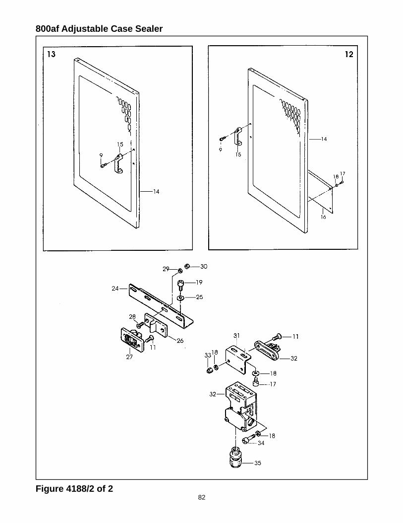
82
800af Adjustable Case Sealer
Figure 4188/2 of 2
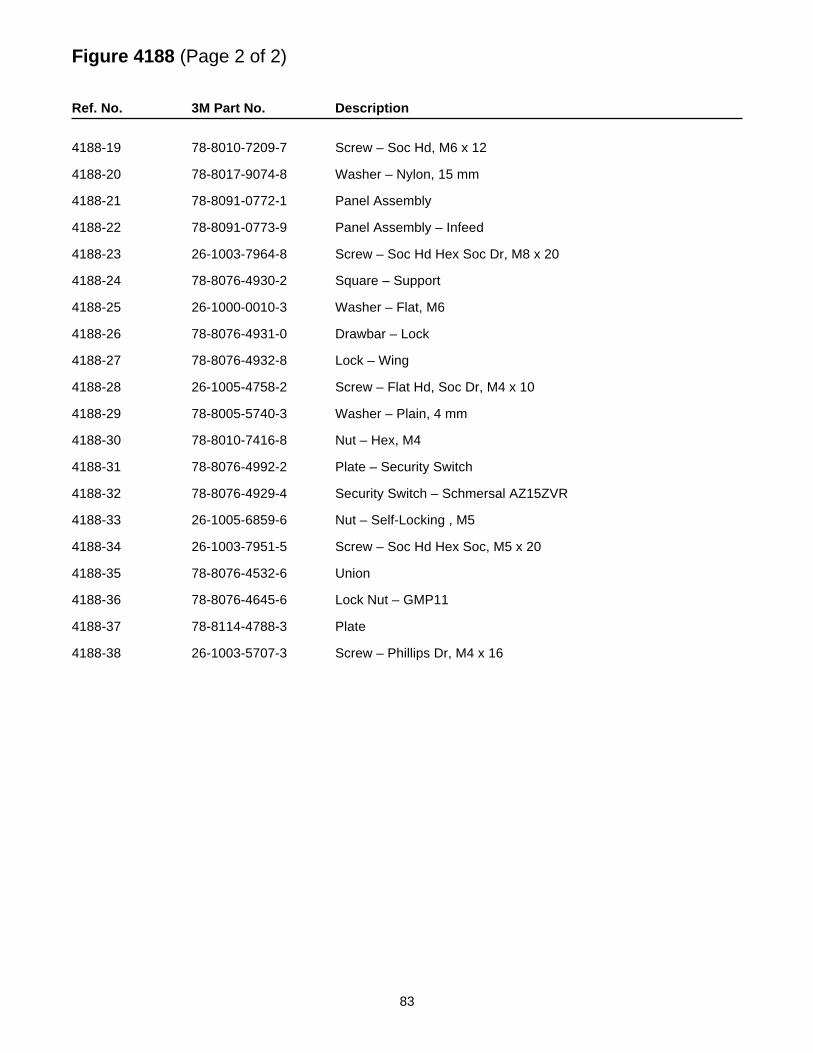
83
Figure 4188 (Page 2 of 2)
Ref. No. 3M Part No. Description
4188-19 78-8010-7209-7 Screw – Soc Hd, M6 x 12
4188-20 78-8017-9074-8 Washer – Nylon, 15 mm
4188-21 78-8091-0772-1 Panel Assembly
4188-22 78-8091-0773-9 Panel Assembly – Infeed
4188-23 26-1003-7964-8 Screw – Soc Hd Hex Soc Dr, M8 x 20
4188-24 78-8076-4930-2 Square – Support
4188-25 26-1000-0010-3 Washer – Flat, M6
4188-26 78-8076-4931-0 Drawbar – Lock
4188-27 78-8076-4932-8 Lock – Wing
4188-28 26-1005-4758-2 Screw – Flat Hd, Soc Dr, M4 x 10
4188-29 78-8005-5740-3 Washer – Plain, 4 mm
4188-30 78-8010-7416-8 Nut – Hex, M4
4188-31 78-8076-4992-2 Plate – Security Switch
4188-32 78-8076-4929-4 Security Switch – Schmersal AZ15ZVR
4188-33 26-1005-6859-6 Nut – Self-Locking , M5
4188-34 26-1003-7951-5 Screw – Soc Hd Hex Soc, M5 x 20
4188-35 78-8076-4532-6 Union
4188-36 78-8076-4645-6 Lock Nut – GMP11
4188-37 78-8114-4788-3 Plate
4188-38 26-1003-5707-3 Screw – Phillips Dr, M4 x 16
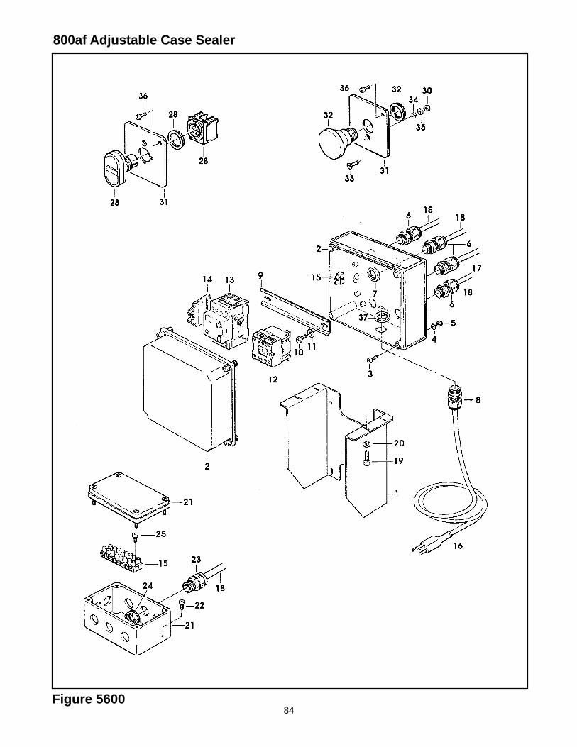
84
800af Adjustable Case Sealer
Figure 5600
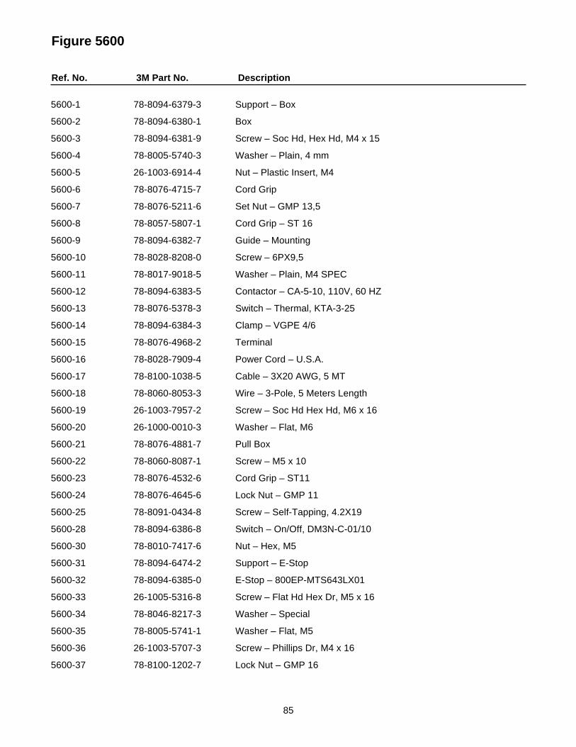
85
Figure 5600
Ref. No. 3M Part No. Description
5600-1 78-8094-6379-3 Support – Box
5600-2 78-8094-6380-1 Box
5600-3 78-8094-6381-9 Screw – Soc Hd, Hex Hd, M4 x 15
5600-4 78-8005-5740-3 Washer – Plain, 4 mm
5600-5 26-1003-6914-4 Nut – Plastic Insert, M4
5600-6 78-8076-4715-7 Cord Grip
5600-7 78-8076-5211-6 Set Nut – GMP 13,5
5600-8 78-8057-5807-1 Cord Grip – ST 16
5600-9 78-8094-6382-7 Guide – Mounting
5600-10 78-8028-8208-0 Screw – 6PX9,5
5600-11 78-8017-9018-5 Washer – Plain, M4 SPEC
5600-12 78-8094-6383-5 Contactor – CA-5-10, 110V, 60 HZ
5600-13 78-8076-5378-3 Switch – Thermal, KTA-3-25
5600-14 78-8094-6384-3 Clamp – VGPE 4/6
5600-15 78-8076-4968-2 Terminal
5600-16 78-8028-7909-4 Power Cord – U.S.A.
5600-17 78-8100-1038-5 Cable – 3X20 AWG, 5 MT
5600-18 78-8060-8053-3 Wire – 3-Pole, 5 Meters Length
5600-19 26-1003-7957-2 Screw – Soc Hd Hex Hd, M6 x 16
5600-20 26-1000-0010-3 Washer – Flat, M6
5600-21 78-8076-4881-7 Pull Box
5600-22 78-8060-8087-1 Screw – M5 x 10
5600-23 78-8076-4532-6 Cord Grip – ST11
5600-24 78-8076-4645-6 Lock Nut – GMP 11
5600-25 78-8091-0434-8 Screw – Self-Tapping, 4.2X19
5600-28 78-8094-6386-8 Switch – On/Off, DM3N-C-01/10
5600-30 78-8010-7417-6 Nut – Hex, M5
5600-31 78-8094-6474-2 Support – E-Stop
5600-32 78-8094-6385-0 E-Stop – 800EP-MTS643LX01
5600-33 26-1005-5316-8 Screw – Flat Hd Hex Dr, M5 x 16
5600-34 78-8046-8217-3 Washer – Special
5600-35 78-8005-5741-1 Washer – Flat, M5
5600-36 26-1003-5707-3 Screw – Phillips Dr, M4 x 16
5600-37 78-8100-1202-7 Lock Nut – GMP 16
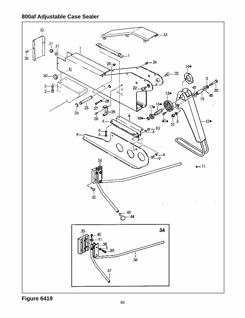
86Figure 6419
800af Adjustable Case Sealer
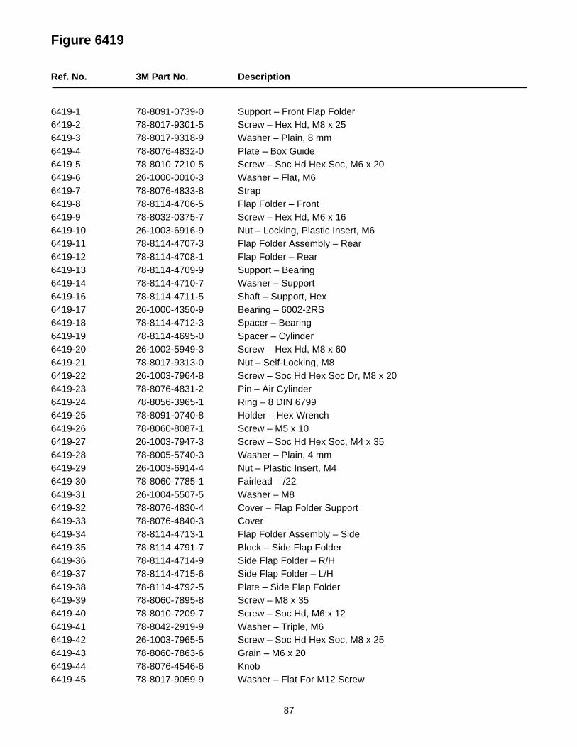
87
Figure 6419
Ref. No. 3M Part No. Description
6419-1 78-8091-0739-0 Support – Front Flap Folder6419-2 78-8017-9301-5 Screw – Hex Hd, M8 x 256419-3 78-8017-9318-9 Washer – Plain, 8 mm6419-4 78-8076-4832-0 Plate – Box Guide6419-5 78-8010-7210-5 Screw – Soc Hd Hex Soc, M6 x 206419-6 26-1000-0010-3 Washer – Flat, M66419-7 78-8076-4833-8 Strap6419-8 78-8114-4706-5 Flap Folder – Front6419-9 78-8032-0375-7 Screw – Hex Hd, M6 x 166419-10 26-1003-6916-9 Nut – Locking, Plastic Insert, M66419-11 78-8114-4707-3 Flap Folder Assembly – Rear6419-12 78-8114-4708-1 Flap Folder – Rear6419-13 78-8114-4709-9 Support – Bearing6419-14 78-8114-4710-7 Washer – Support6419-16 78-8114-4711-5 Shaft – Support, Hex6419-17 26-1000-4350-9 Bearing – 6002-2RS6419-18 78-8114-4712-3 Spacer – Bearing6419-19 78-8114-4695-0 Spacer – Cylinder6419-20 26-1002-5949-3 Screw – Hex Hd, M8 x 606419-21 78-8017-9313-0 Nut – Self-Locking, M86419-22 26-1003-7964-8 Screw – Soc Hd Hex Soc Dr, M8 x 206419-23 78-8076-4831-2 Pin – Air Cylinder6419-24 78-8056-3965-1 Ring – 8 DIN 67996419-25 78-8091-0740-8 Holder – Hex Wrench6419-26 78-8060-8087-1 Screw – M5 x 106419-27 26-1003-7947-3 Screw – Soc Hd Hex Soc, M4 x 356419-28 78-8005-5740-3 Washer – Plain, 4 mm6419-29 26-1003-6914-4 Nut – Plastic Insert, M46419-30 78-8060-7785-1 Fairlead – /226419-31 26-1004-5507-5 Washer – M86419-32 78-8076-4830-4 Cover – Flap Folder Support6419-33 78-8076-4840-3 Cover6419-34 78-8114-4713-1 Flap Folder Assembly – Side6419-35 78-8114-4791-7 Block – Side Flap Folder6419-36 78-8114-4714-9 Side Flap Folder – R/H6419-37 78-8114-4715-6 Side Flap Folder – L/H6419-38 78-8114-4792-5 Plate – Side Flap Folder6419-39 78-8060-7895-8 Screw – M8 x 356419-40 78-8010-7209-7 Screw – Soc Hd, M6 x 126419-41 78-8042-2919-9 Washer – Triple, M66419-42 26-1003-7965-5 Screw – Soc Hd Hex Soc, M8 x 256419-43 78-8060-7863-6 Grain – M6 x 206419-44 78-8076-4546-6 Knob6419-45 78-8017-9059-9 Washer – Flat For M12 Screw
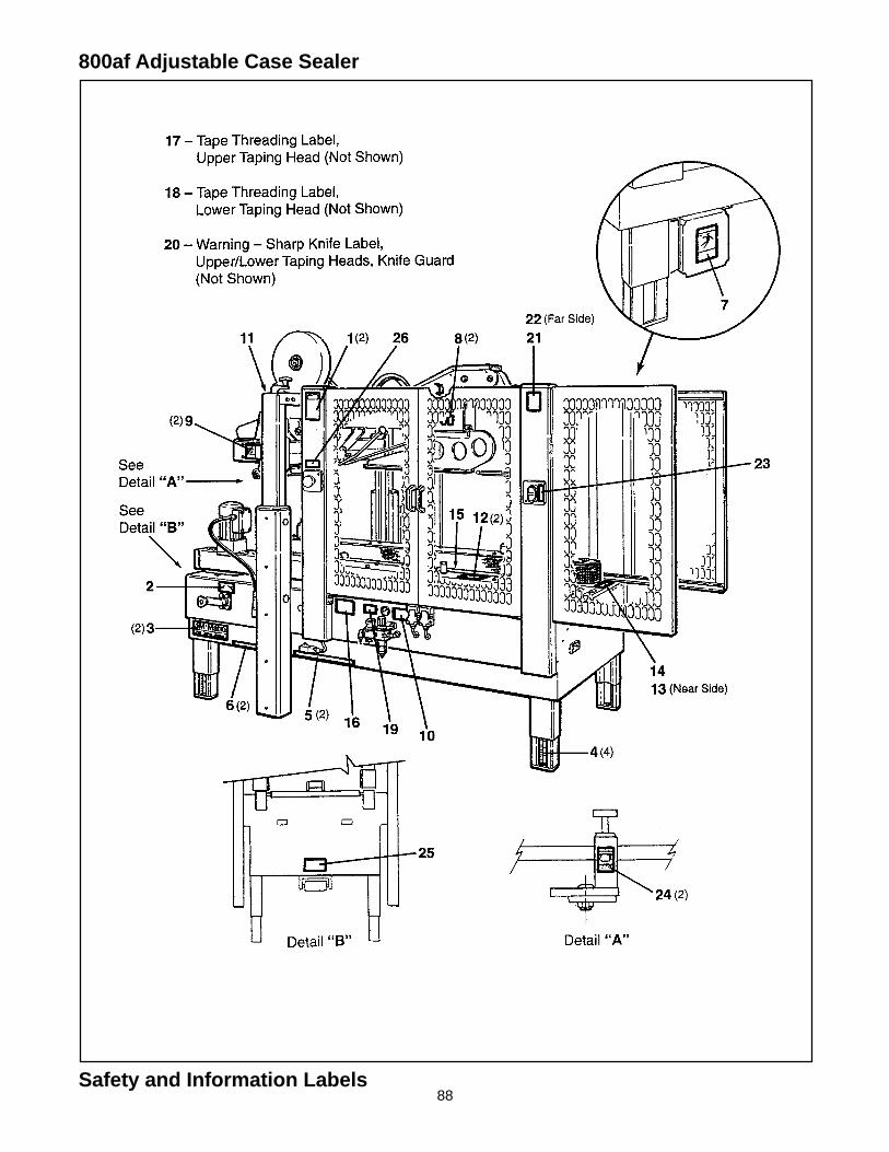
88
800af Adjustable Case Sealer
Safety and Information Labels
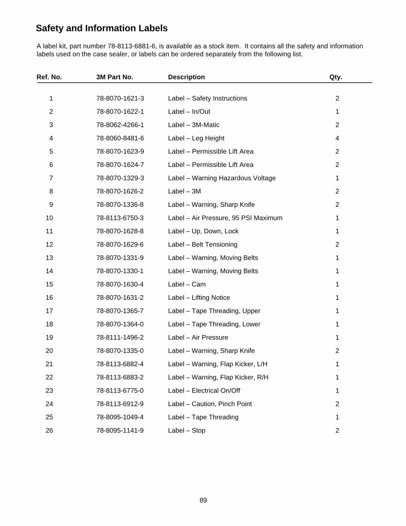
89
Safety and Information Labels
A label kit, part number 78-8113-6881-6, is available as a stock item. It contains all the safety and informationlabels used on the case sealer, or labels can be ordered separately from the following list.
Ref. No. 3M Part No. Description Qty.
1 78-8070-1621-3 Label – Safety Instructions 2
2 78-8070-1622-1 Label – In/Out 1
3 78-8062-4266-1 Label – 3M-Matic 2
4 78-8060-8481-6 Label – Leg Height 4
5 78-8070-1623-9 Label – Permissible Lift Area 2
6 78-8070-1624-7 Label – Permissible Lift Area 2
7 78-8070-1329-3 Label – Warning Hazardous Voltage 1
8 78-8070-1626-2 Label – 3M 2
9 78-8070-1336-8 Label – Warning, Sharp Knife 2
10 78-8113-6750-3 Label – Air Pressure, 95 PSI Maximum 1
11 78-8070-1628-8 Label – Up, Down, Lock 1
12 78-8070-1629-6 Label – Belt Tensioning 2
13 78-8070-1331-9 Label – Warning, Moving Belts 1
14 78-8070-1330-1 Label – Warning, Moving Belts 1
15 78-8070-1630-4 Label – Cam 1
16 78-8070-1631-2 Label – Lifting Notice 1
17 78-8070-1365-7 Label – Tape Threading, Upper 1
18 78-8070-1364-0 Label – Tape Threading, Lower 1
19 78-8111-1496-2 Label – Air Pressure 1
20 78-8070-1335-0 Label – Warning, Sharp Knife 2
21 78-8113-6882-4 Label – Warning, Flap Kicker, L/H 1
22 78-8113-6883-2 Label – Warning, Flap Kicker, R/H 1
23 78-8113-6775-0 Label – Electrical On/Off 1
24 78-8113-6912-9 Label – Caution, Pinch Point 2
25 78-8095-1049-4 Label – Tape Threading 1
26 78-8095-1141-9 Label – Stop 2