800 series utilities and ground … series . utilities and ground improvements facilities . ... 2...
TRANSCRIPT
UFC 2-000-05N
800 Series - i
800 SERIES UTILITIES AND GROUND IMPROVEMENTS FACILITIES
Table of Contents 810 ELECTRIC POWER .............................................................................................. 1
810-1 DEFINITION ............................................................................................... 1
811 ELECTRIC POWER-SOURCE ............................................................................. 2
811 09 ELECTRIC POWER PLANT BUILDING (SF) .............................................. 2
811 10 - 811 50 ELECTRIC POWER PLANTS ........................................................ 3
811 10 ELECTRIC POWER PLANT - DIESEL (KW) ............................................... 3
811 25 ELECTRIC POWER PLANT - STEAM TURBINE (KW) .............................. 4
811 45 ELECTRIC POWER PLANT - GAS TURBINE (KW) ................................... 4
811 46 ELECTRIC POWER PLANT - WIND TURBINE (KW) ................................. 5
811 50 ELECTRIC POWER - PHOTOVOLTAIC SYSTEM (KW) ............................ 5
811 59 STANDBY GENERATOR BUILDING (SF) .................................................. 5
811 60 STANDBY GENERATOR PLANT (KW) ...................................................... 6
812 ELECTRIC POWER TRANSMISSION AND DISTRIBUTION LINES .................... 7
812 09 ELECTRIC DISTRIBUTION BUILDING (SF) ............................................... 7
812 12 TRANSFORMERS (KV) .............................................................................. 8
812 20 STREET LIGHTING (LF) ............................................................................. 8
812 31 OVERHEAD ELECTRICAL DISTRIBUTION LINES (LF) ............................ 9
812 32 UNDERGROUND ELECTRICAL DISTRIBUTION LINES (LF) .................... 9
812 40 PERIMETER AND SECURITY LIGHTING (LF) ......................................... 10
813 ELECTRIC POWER SUBSTATIONS AND SWITCHING STATIONS ................. 10
813 10 SWITCHING STATION / SUBSTATION BUILDING (SF) .......................... 10
813 20 SUBSTATIONS (KV) ................................................................................. 11
813 30 SWITCHING STATION FOR SECTIONALIZED DISTRIBUTION CIRCUITS (KV) ........................................................................................................... 11
820 HEAT AND REFRIGERATION (A/C) ................................................................. 12
820-1 HEAT AND REFRIGERATION ................................................................. 12
821 HEAT SOURCE ................................................................................................. 12
821-1 HEAT SOURCE ........................................................................................ 12
821 09 - 821 50 HEATING PLANTS ...................................................................... 12
821 09 HEATING PLANT BUILDING (SF) ............................................................ 13
821 12 HEATING PLANT- OIL / GAS (MB) ........................................................... 13
UFC 2-000-05N
800 Series - ii
821 22 HEATING PLANT- COAL (MB) ................................................................. 13
821 30 HEATING PLANT- NON - FOSSIL FUEL (MB) ......................................... 14
821 40 STEAM PLANT - NUCLEAR (MB) ............................................................. 15
821 60 - 821 61 HEATING FUEL OIL STORAGE ................................................... 15
821 60 DISTILLATE HEATING FUEL OIL STORAGE (GA) .................................. 17
821 61 RESIDUAL HEATING FUEL OIL STORAGE (GA) .................................... 17
822 HEAT TRANSMISSION AND DISTRIBUTION LINES........................................ 17
822-1 HEAT TRANSMISSION AND DISTRIBUTION LINES .............................. 17
822 09 STEAM / HEAT BUILDING / SHELTER (SF) ............................................ 18
822 10 CONDENSATE RETURN PUMP STATION (EA) ...................................... 18
822 12 STEAM LINES (LF) ................................................................................... 18
822 14 CONDENSATE LINES (LF) ....................................................................... 19
822 16 HOT WATER LINES (LF) .......................................................................... 19
822 26 HIGH TEMPERATURE HOT WATER LINES (LF) .................................... 20
823 HEAT/GAS-SOURCE ......................................................................................... 20
823-1 HEAT/ GAS-SOURCE .............................................................................. 20
823 09 GAS GENERATING BUILDING (SF) ........................................................ 20
823 10 GAS GENERATING PLANT (MB) ............................................................. 20
823 15 GAS METER BUILDING (SF) .................................................................... 21
823 20 GAS STORAGE TANKS (CF) ................................................................... 21
824 HEAT/GAS TRANSMISSION ............................................................................. 21
824-1 HEAT/ GAS TRANSMISSION. ................................................................. 21
824 10 GAS MAINS (LF) ....................................................................................... 22
826 REFRIGERATION/AIR CONDITIONING ............................................................ 22
826 10 - 826 40 COOLING SYSTEM PLANTS ...................................................... 22
826 10 COOLING SYSTEM PLANT BUILDING (SF) ............................................ 22
826 20 COOLING SYSTEM PLANT (TR) .............................................................. 23
827 CHILLED WATER-AIR CONDITIONING TRANSMISSION/DISTRIBUTION ...... 23
827-1 CHILLED WATER-AIR CONDITIONING TRANSMISSION / DISTRIBUTION. ........................................................................................ 23
827 10 COOLING SYSTEM VALVE BUILDING (SF) ............................................ 23
827 20 CHILLED FLUID LINES (LF) ..................................................................... 24
830 SEWAGE AND WASTE ..................................................................................... 24
830-1 DEFINITION ............................................................................................. 24
831 SEWAGE AND INDUSTRIAL WASTE, TREATMENT AND DISPOSAL ............. 24
UFC 2-000-05N
800 Series - iii
831/83109/83110-1 DEFINITION ............................................................................ 25
831 09 SEWAGE TREATMENT BUILDING (SF) .................................................. 25
831 10 SEWAGE TREATMENT PLANT (KG) ....................................................... 25
831 11 - 831 16 SPECIALIZED TREATMENT FACILITIES .................................... 26
831 11 BALLAST CONTAMINATION SKIMMER (KG) .......................................... 26
831 14 INDUSTRIAL WASTEWATER TREATMENT BUILDING (SF) .................. 26
831 15 INDUSTRIAL WASTEWATER TREATMENT FACILITY (KG)................... 26
831 16 OIL/WATER SEPARATOR (KG) ............................................................... 27
831 20 OUTFALL SEWER LINE (KG) ................................................................... 27
831 30 SEPTIC TANK AND DRAIN FIELD (GA) ................................................... 27
831 31 SEPTIC LAGOON AND / OR SETTLEMENT POND (GA) ........................ 28
831 39 RADIOACTIVE WASTE HANDLING BUILDING (SF) ............................... 28
831 40 RADIOACTIVE WASTE HANDLING FACILITY (EA) ................................ 28
831 41 HAZARDOUS WASTE STORAGE AND TRANSFER FACILITY (EA) ...... 28
831 42 HAZARDOUS WASTE STORAGE AREA (SY) ......................................... 30
831 43 HAZARDOUS WASTE STORAGE BUILDING (SF) .................................. 31
832 SEWAGE AND INDUSTRIAL WASTE - COLLECTION ..................................... 31
832-1 DEFINITION ............................................................................................. 31
832 10 SANITARY SEWER LINE (LF) .................................................................. 31
832 20 COMBINED SEWER LINE (LF) ................................................................. 31
832 29 SEWAGE PUMP STATION BUILDING (SF) ............................................. 32
832 30 SEWAGE WASTE PUMP STATION (EA) ................................................. 32
832 40 INDUSTRIAL WASTEWATER LINE (LF) .................................................. 33
832 41 INDUSTRIAL WASTEWATER PUMP STATION (EA) ............................... 33
833 SOLID WASTE MANAGEMENT ........................................................................ 34
833-1 DEFINITION OF SOLID WASTE .............................................................. 34
833 09 INCINERATOR BUILDING AND INCINERATOR (TN) .............................. 34
833 10 INCINERATOR - EXTERIOR (TN) ............................................................ 34
833 15 SANITARY/CUT-FILL DISPOSAL AREA (EA) .......................................... 35
833 20 GARBAGE GRINDER BUILDING (SF) ..................................................... 35
833 21 GARBAGE GRINDER (TN) ....................................................................... 35
833 30 GARBAGE STAND (EA) ........................................................................... 35
833 40 GARBAGE HOUSE (SF) ........................................................................... 35
840 WATER FACILITIES .......................................................................................... 36
UFC 2-000-05N
800 Series - iv
840-1 DEFINITION. ............................................................................................ 36
841 POTABLE WATER - SUPPLY, TREATMENT, AND STORAGE ......................... 36
841-1 DEFINITION ............................................................................................. 36
841 09 WATER TREATMENT FACILITY BUILDING (SF) .................................... 37
841 10 WATER TREATMENT PLANT - POTABLE (KG) ...................................... 37
841 15 NUCLEAR REACTOR WATER TREATMENT FACILITY (KG) ................. 37
841 20 WATER SUPPLY LINE (LF) ...................................................................... 37
841 25 DESALINIZATION PLANT (KG) ................................................................ 38
841 30 STORAGE TANKS - ELEVATED, POTABLE (GA) ................................... 38
841 40 STORAGE TANKS - GROUND LEVEL, POTABLE (GA) .......................... 38
841 50 WATER WELLS - POTABLE (KG) ............................................................ 39
841 51 RESERVOIR - POTABLE WATER (MG) ................................................... 39
841 52 WATER CATCHMENT STRUCTURE (GA)............................................... 39
842 WATER DISTRIBUTION SYSTEM, POTABLE .................................................. 40
842 09 WATER DISTRIBUTION BUILDING, POTABLE (SF) ............................... 40
842 10 WATER DISTRIBUTION LINE, POTABLE (LF) ........................................ 40
842 15 PUMP STATION - POTABLE WATER (KG).............................................. 40
843 WATER, FIRE PROTECTION ............................................................................ 41
843 10 FIRE PROTECTION LINES (LF) ............................................................... 43
843 20 FIRE PROTECTION PUMP STATION (KG).............................................. 43
843 30 WATER STORAGE TANK - FIRE PROTECTION WATER (MG) .............. 44
843 35 RESERVOIRS - FIRE PROTECTION WATER (MG) ................................ 44
843 40 WELLS - FIRE PROTECTION WATER (GM) ............................................ 44
843 50 FIRE PROTECTION BUILDING (SF) ........................................................ 44
844 WATER SUPPLY/STORAGE, NONPOTABLE WATER ..................................... 45
844-1 DEFINITION ............................................................................................. 45
844 10 WATER DISTRIBUTION BUILDING, NONPOTABLE WATER (SF) ........ 45
844 20 WELLS - NONPOTABLE WATER (KG) .................................................... 45
844 30 PUMP STATION - NONPOTABLE WATER (KG) ...................................... 46
844 40 STORAGE TANKS - NONPOTABLE WATER (GA) .................................. 46
844 50 RESERVOIRS - NONPOTABLE WATER (MG) ........................................ 46
845 WATER DISTRIBUTION SYSTEM - NONPOTABLE .......................................... 47
845 20 WATER DISTRIBUTION LINE, NONPOTABLE (LF) ................................ 47
850 ROADS AND STREETS...................................................................................... 47

UFC 2-000-05N
800 Series - v
851 10 ROADS (SY) .............................................................................................. 47
851 11 ROADS, UNSURFACED (SY) ................................................................... 47
851 15 LOAD/UNLOAD RAMP (SY) ..................................................................... 47
851 20 VEHICULAR BRIDGES (SY) ..................................................................... 48
851 21 VEHICULAR PARKING, UNSURFACED (SY) .......................................... 48
851 22 VEHICLE STAGING AREA (SY) ............................................................... 48
851 23 TRAFFIC CONTROL SIGNALS (EA) ........................................................ 48
851 25 VEHICULAR TUNNELS (LF) ..................................................................... 49
852 SIDEWALKS AND OTHER PAVEMENTS ......................................................... 49
852 10 PARKING AREA (SY) ............................................................................... 49
852 15 PARKING BUILDING, BICYCLE (SF) ....................................................... 53
852 20 SIDEWALK (SY) ........................................................................................ 53
852 30 PEDESTRIAN BRIDGES (SY) .................................................................. 53
852 35 OTHER PAVED AREAS NOT CODED IN THE 100 OR 400 SERIES (SY)53
852 40 MISCELLANEOUS OPEN STORAGE OR LAYDOWN AREA (SY) .......... 53
852 41 BUILDING/TRAILER PAD WITH UTILITY CONNECTIONS (SY) ............. 54
853 PARKING BUILDINGS, MISCELLANEOUS ....................................................... 54
853 10 PARKING BUILDING (SF)......................................................................... 54
860 RAILROAD TRACKS.......................................................................................... 54
860-1 RAILROAD TRACKS DESCRIPTION ...................................................... 54
860 10 RAILROAD TRACKAGE (MI) .................................................................... 55
860 20 EXPLOSIVE BARRICADE FOR SUSPECT TRUCKS AND RAILROAD CARS (EA) ................................................................................................ 55
860 30 RAILROAD BRIDGE AND TRESTLE (MI) ................................................ 55
860 40 CRANE TRACKAGE (MI) .......................................................................... 55
860 41 RAILROAD SCALEHOUSE (SF) ............................................................... 56
870 GROUND IMPROVEMENT STRUCTURES ...................................................... 56
871 GROUNDS, DRAINAGE .................................................................................... 56
871 10 STORM SEWER (LF) ................................................................................ 56
871 11 OIL/WATER SEPARATOR - RUNOFF WATER (KG) ............................... 56
871 15 STORM WATER PUMPING STATION (EA) ............................................. 56
871 16 STORMWATER RETENTION PONDS (MG) ............................................ 57
871 20 DRAINAGE DITCH (LF) ............................................................................ 57
871 25 DAM (LF) ................................................................................................... 57
UFC 2-000-05N
800 Series - vi
871 26 LEVEE AND/OR DIKE (LF) ....................................................................... 58
871 30 IRRIGATION FACILITY (LF) ..................................................................... 58
871 35 RETAINING WALL (LF) ............................................................................. 58
871 45 DREDGED SPOIL HANDLING FACILITY (GM) ........................................ 58
872 GROUNDS FENCING, GATES AND GUARD TOWERS .................................... 58
872-1 DEFINITION ............................................................................................. 58
872 10 STATION SECURITY AND PERIMETER FENCING AND WALLS (LF) ... 59
872 11 HARDENED SECURITY FENCE (SF) ...................................................... 60
872 15 INTERIOR FENCING (NOT CODED IN 872 10) (LF) ............................... 61
872 20 GUARD AND WATCH TOWERS (EA) ...................................................... 61
872 30 MECHANICAL SECURITY BARRICADE (EA) .......................................... 62
880 FIRE AND OTHER ALARM SYSTEMS .............................................................. 62
880-1 FIRE AND OTHER ALARM SYSTEMS .................................................... 62
880 10 FIRE ALARM SYSTEM (MI) ...................................................................... 62
880 20 WATCH REPORTING SYSTEM (MI) ........................................................ 63
880 30 BASE ALERT SYSTEMS (MI) ................................................................... 64
880 40 AIR CRASH/ALERT (MI) ........................................................................... 64
890 MISCELLANEOUS UTILITIES ........................................................................... 64
890 09 MISCELLANEOUS UTILITY BUILDING (SF) ............................................ 64
890 10 ACETYLENE PLANT (EA) ........................................................................ 64
890 11 ACETYLENE DISTRIBUTION SYSTEM (LF) ............................................ 64
890 15 NITROGEN PLANT (EA) ........................................................................... 65
890 18 UTILITY VAULT (EA) ................................................................................ 65
890 20 COMPRESSED AIR PLANT (EA) ............................................................. 65
890 21 COMPRESSED AIR DISTRIBUTION SYSTEM (LF) ................................. 65
890 25 CARBON DIOXIDE PLANT (EA) ............................................................... 66
890 27 ICE-MAKING PLANT (TN) ........................................................................ 66
890 30 INDUSTRIAL OXYGEN PLANT (EA) ........................................................ 66
890 31 OXYGEN DISTRIBUTION SYSTEM (LF) .................................................. 66
890 45 VALVE HOUSE OR OTHER SHED/SHELTER (SF) ................................. 66
890 46 UTILITY TUNNEL (LF) .............................................................................. 67
890 50 ICS COMMUNICATION LINES (MI) .......................................................... 67
890 51 ICS MONITORING STATION (SF) ............................................................ 67
890 56 WEIGHTING FACILITY (EA) ..................................................................... 76
UFC 2-000-05N
800 Series - vii
890 77 STORAGE FOR UTILITY SYSTEMS (READY ISSUE/SHOP STORES/MISC.) (SF) ................................................................................ 76
893 MISCELLANEOUS UTILITIES-LINEAR FEET ................................................... 76
893 20 UTILITY CHANNEL (LF) ........................................................................... 76
UFC 2-000-05N
800 Series - 1
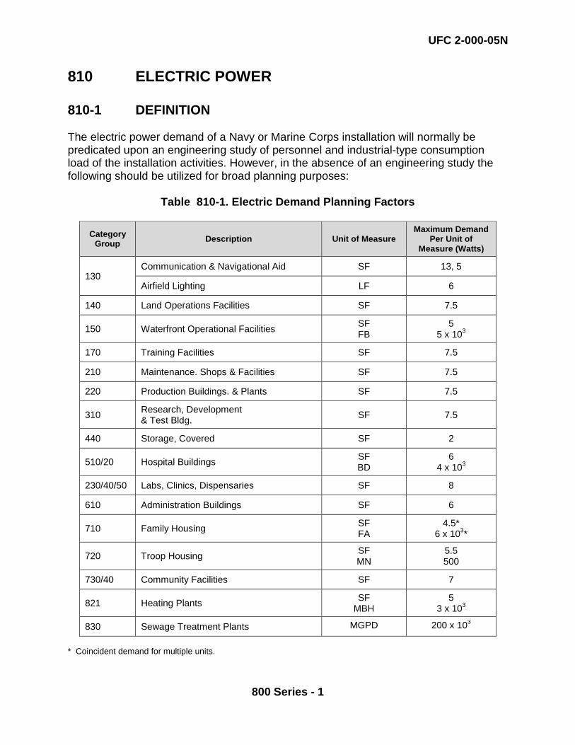
810 ELECTRIC POWER 810-1 DEFINITION The electric power demand of a Navy or Marine Corps installation will normally be predicated upon an engineering study of personnel and industrial-type consumption load of the installation activities. However, in the absence of an engineering study the following should be utilized for broad planning purposes:
Table 810-1. Electric Demand Planning Factors
Category Group Description Unit of Measure
Maximum Demand Per Unit of
Measure (Watts)
130 Communication & Navigational Aid SF 13, 5
Airfield Lighting LF 6
140 Land Operations Facilities SF 7.5
150 Waterfront Operational Facilities SF FB
5 5 x 10³
170 Training Facilities SF 7.5
210 Maintenance. Shops & Facilities SF 7.5
220 Production Buildings. & Plants SF 7.5
310 Research, Development & Test Bldg. SF 7.5
440 Storage, Covered SF 2
510/20 Hospital Buildings SF BD
6 4 x 10³
230/40/50 Labs, Clinics, Dispensaries SF 8
610 Administration Buildings SF 6
710 Family Housing SF FA
4.5* 6 x 103*
720 Troop Housing SF MN
5.5 500
730/40 Community Facilities SF 7
821 Heating Plants SF MBH
5 3 x 10³
830 Sewage Treatment Plants MGPD 200 x 103
* Coincident demand for multiple units.
UFC 2-000-05N
800 Series - 2
811 ELECTRIC POWER-SOURCE 811-1 DEFINITION. Electric power for base facilities is normally derived from local commercial sources. Where commercial sources are used, transformer substations are required to transform the electrical energy to satisfy the station's load requirement. Category Code Numbers (CCNs) 81110, 81125, 81145, 81146, and 81150 power generation plants may be used as a primary power source in lieu of commercial power or for reducing dependency on commercial power. CCN 81160 may only be used for standby power generation plants. Primary power generation plants are real property. Standby generator plants may be real or personal property, depending on what they support. In general, a standby generator shall be considered real property if it supports real property and shall be considered personal property if it supports personal property. See OPNAVINST 11010.20H, Chapter 1, Paragraph 2c for definitions of real property and personal property. 811-2 PROPERTY RECORD CARD. Regardless of whether the real property power plant is within the footprint of another building, in a standalone building, sheltered by a structure or on a pad, or if it is generating primary or auxiliary power, the primary power or standby power generator plant is assigned its own property record card. If the power plant is located within a standalone building, use CCN 81109 for primary power plants or CCN 81159 for standby power plants. 811 09 ELECTRIC POWER PLANT BUILDING (SF) FAC 8910 BFR Required: N Revised: August 2015 81109-1 DEFINITION. This category code is used for the buildings or shelters that house the electric power plant and associated equipment included in category codes 81110, 81125, 81145, 81146, 81150 and 81160. If an access road is required, the road is inventoried separately; see 85110 and 85111 for more information. 81109-2 PROPERTY RECORD CARD USAGE. Each electric power plant building, shelter or pad should be captured on a single, individual property record card as a structure. If a separate standalone building is used, then CCN 81109 should be assigned as the utilization on that property record card. If the power generation plant is housed in an existing multi-purpose facility, then the space used for the power generation plant should be assigned a utilization of 81109.
UFC 2-000-05N
800 Series - 3
811 10 - 811 50 ELECTRIC POWER PLANTS 81110/81150 – 1 DEFINITION. Consideration as to whether an electric power generating plant is to be planned will depend on the station's geographical location, the availability of a firm uninterrupted adequate power supply from a local electric utility, the economics of using byproduct steam for space heating and industrial process work, and the availability of the required fuel. The electric generating plant (diesel or steam) shall have a total installed capacity equal to the station’s total kilowatt demand and in the case of diesel generators there must be one additional standby generating unit with a capacity equal to the largest unit on the line. In the planning and determination of power plant capacity, due consideration should be given to the estimated demand of all of the station's consumption, both domestic and industrial, plus the anticipated load growth. For initial planning purposes, power plant capacity may be computed by either (1) utilizing the factors indicated under 810 above, or (2) totaling all of the estimated demands in kilowatts of all existing and proposed station buildings and multiplying this total by an appropriate diversity factor. Where a diversity factor is not provided, a factor of eighty percent (80%) may be used. The resultant total is the estimated power plant capacity or the estimated amount of electrical power needed by the station facilities. 811 10 ELECTRIC POWER PLANT - DIESEL (KW) FAC 8111 BFR Required: N Revised: August 2015 81110-1 DEFINITION. This category code is used for power plants that use diesel generators as the primary power source for the production of electricity. Additionally, these plants may also be used in auxiliary capacity for peak shaving or other energy reduction. This category includes all necessary equipment for the production of the commodity including fuel tanks, pumps, electrical equipment, plant controls, and all required process equipment for commodity generation. Dual-fuel engines and piston engines utilizing natural gas or other alternate fuels will use this category code. 81110-2 PROPERTY RECORD CARD USAGE. All equipment is inclusive to the power generation plant and shall not be accounted for separately. The power generation plant should be captured on a single, individual property record card. Any switching stations or substations located inside or outside the power plant but associated with the power distribution system of the installation should be shown on a separate property record card. The building that houses the power plant should be reflected on a separate property record card; see 81109 for more information.
UFC 2-000-05N
800 Series - 4
811 25 ELECTRIC POWER PLANT - STEAM TURBINE (KW) FAC 8111 BFR Required: N Revised: August 2015 81125-1 DEFINITION. A central plant using steam turbine generators for the production of electricity. This category includes all necessary equipment for the production of the commodity. Included are fuel tanks, pumps, electrical equipment, and all required process equipment for commodity generation. The primary unit of measure is kilowatts of generation installed (KW). NOTE: All cogeneration plants should be classified using Category Code 81125. A steam turbine typically uses coal, natural gas, or fuel oil, but could also use refuse or a nuclear energy source. Each of these fuel sources has differing components and storage requirements that would be noted during an asset evaluation, but that are considered real property installed equipment (RPIE) of the plant and not called out as separate facilities (e.g., a conveyor system for delivery of coal or storage tanks for fuel). 81125-2 PROPERTY RECORD CARD USAGE. All equipment internal to the power plant shall be included on an individual property record card. Any switching stations or substations located inside or outside the power plant that are associated with the power distribution system of the installation should be shown on a separate property record card. The building that houses the power plant should be on a separate property record card using CCN 81109. 811 45 ELECTRIC POWER PLANT - GAS TURBINE (KW) FAC 8111 BFR Required: N Revised: August 2015 81145-1 DEFINITION. A central plant using gas fired turbine generators for the production of electricity. This category includes all necessary equipment for the production of the commodity. Included are fuel tanks, pumps, electrical equipment, and all required process equipment for commodity generation. The primary unit of measure is kilowatts of generation installed (KW). A gas turbine is typically run off of a jet propellant (JP) fuel source. Gas turbines are a source of primary power and are classified as real property. 81145-2 PROPERTY RECORD CARD USAGE. All equipment internal to the power plant should be included on a single, individual property record card. Any switching stations or substations located inside or outside the power plant but associated with the power distribution system of the installation should be shown on a separate property record card.
UFC 2-000-05N
800 Series - 5
811 46 ELECTRIC POWER PLANT - WIND TURBINE (KW) FAC 8114 BFR Required: N Revised: August 2015 81146-1 DEFINITION. A central plant using wind turbines for the production of electricity. This category includes all necessary equipment for commodity generation. The primary unit of measure is kilowatts of generation installed (KW). These plants generate electricity by capturing the kinetic energy of the wind to drive the turbine. This power generation source is a form of renewable energy and is primarily used for energy reduction. Wind turbines are a passive source of primary power and shall be considered real property. 81146-2 PROPERTY RECORD CARD USAGE. The equipment internal to the power plant should be included on an individual property record. Any switching stations or substations associated with the power distribution system of the installation should be shown on a separate property record card. 811 50 ELECTRIC POWER - PHOTOVOLTAIC SYSTEM (KW) FAC 8115 BFR Required: N Revised: August 2015 81150-1 DEFINITION. A power source using photovoltaic (PV) panels for the production of electricity. This category code includes all necessary equipment for the production of the commodity. These plants generate electrical power by converting sunlight into direct current electricity using semiconducting panels. This power generation source is a form of renewable energy and is primarily used for energy reduction. PV systems are a passive source of primary power and are classified as real property. 81150-2 PROPERTY RECORD CARD USAGE. All photovoltaic systems are classified as real property and inventoried in iNFADS. All equipment associated with a photovoltaic system shall be included on a single property record card. The primary unit of measure is the rated output capacity of the inverter in kilowatts (KW) generated by the PV system. Note that roof top mounted units are typically maintained by the tenant command, whereas carport mounted and/or ground mounted units are maintained by the public works utilities department. 811 59 STANDBY GENERATOR BUILDING (SF) FAC 8910 BFR Required: N Revised: August 2015

UFC 2-000-05N
800 Series - 6
81159-1 DEFINITION. This category code is used for standalone buildings associated with emergency standby generator plants (81160). 81159-2 PROPERTY RECORD CARD USAGE. Each building shall be recorded on an individual property record card. All equipment associated with a standby generator plant shall be included on a separate property record card utilizing CCN 81160. 811 60 STANDBY GENERATOR PLANT (KW) FAC 8112 BFR Required: N Revised: August 2015 81160-1 DEFINITION. Standby generator plants include all necessary equipment for the production of power. Such equipment may include day tanks, pumps, power panels, switchgear, controls, battery storage, and automated transfer switches. When dealing with standby generator plants, it is necessary to verify the characteristics of the plant with appropriate facility POC to ensure accuracy of real property status and rated capacity (KW). There are several categories of standby generator plants:
a. Utilities Standby Power - Utilities standby power generation plants act as auxiliary sources of power and do not require full-time operation. Utilities standby generation plants serve utility production and distribution facilities such as water treatment plants or sewage lift stations, during power outages. Utilities standby power generation plants are classified as real property. b. Emergency Standby Power - Emergency standby power generation plants provide power upon loss of the primary power source and are classified as Emergency Systems by NFPA 70. They are essential for safety to human life and legally required by municipal, state, federal or other codes or by a governmental agency having jurisdiction. Examples include generators for hospitals or air traffic control towers. Emergency standby power generation plants are classified as real property.
c. Mission Specific Standby Power – Mission specific standby power generation plants support mission specific operations. These essential loads must be supported with emergency standby power generation and provide an adequate uninterrupted power supply in the event (and throughout the period) of power outages and other emergencies. There are two types of mission specific standby power.
1. Where an entire operation must be supported with power, (such as a command operation center, SCIF, or other mission essential operation), these mission specific standby power generators may support a single
UFC 2-000-05N
800 Series - 7
building, multiple buildings or a space within the building. Since these generators are supporting a real property, these mission specific standby power generators and associated UPS systems would be classified as real property.
2. Where only critical personal property equipment such as servers, computer room air conditioning (CRAC) units or other telecommunication gear is supported, these generators and associated UPS will be classified as personal property. In these instances, the generators are sized only to support specific critical pieces of personal property equipment. These generators would not be used for building system or task lighting, central or comfort air conditioning system, or power to support personnel operations.
81160-2 PROPERTY RECORD CARD USAGE. A real property standby generator plant should be inventoried on its own property record card. The associated plant equipment (day tanks, UPS, battery bank, transfer switch, etc.) is classified as Real Property Installed Equipment (RPIE) and should not be inventoried separately. Bulk fuel storage tanks must be inventoried separately. Whether real or personal property, in many instances CNIC will not be owner or operator of the standby generator plant and the maintenance fund source codes will vary accordingly. There are many possible owner-operators that could have maintenance responsibility, including CNIC, NAVAIR, NAVFAC, or other non-Navy tenant command such as DLA or BUMED. The primary unit of measure is the rated capacity in kilowatts (KW) generated. 812 ELECTRIC POWER TRANSMISSION AND
DISTRIBUTION LINES 812-1 DEFINITION. Distribution and transmission lines are required to supply electricity to buildings, street lighting, floodlighting, and perimeter lighting. Lines may be either overhead or underground and will include poles, duct banks, and controls to distribute electrical energy from the source to each using facility. Planning for distribution and transmission lines will require engineering calculation of critical power demand loads and future load growth. Airfield pavement lighting is planned as described under Category Code 136. 812 09 ELECTRIC DISTRIBUTION BUILDING (SF) FAC 8910 BFR Required N 81209-1 DEFINITION. This category code should be used for buildings associated with electric distribution system that are not included under Switching
UFC 2-000-05N
800 Series - 8
Station/Substation buildings, Category Code 813 10. This Category Code will rarely be used. The unit of measure is square feet. 81209 – 2 PROPERTY RECORD CARD USAGE. Each building should be on a single property record card using facility type code of 2. 812 12 TRANSFORMERS (KV) FAC 8133 BFR Required N 81212-1 DEFINITION. Transformers transform electrical power on the primary side to a lower or higher voltage on the secondary side to serve a facility or several facilities. Use the kilovolt ampere (KVA) rating that is found on the nameplate on the transformer or obtained from the manufacturer. It is the lowest rating when multiple ratings are provided (i.e. 12000/16000/20000 – OA/FA/FOA)]. The primary unit of measure is kilovolt ampere (KV) and the alternate unit of measure of EA should be entered into iNFADS. Enter the alternate unit of measure, each (EA), by including the total quantity of transformers listed on the record. 81212-2 PROPERTY RECORD CARD USAGE. A separate property record card shall be created which aggregates all distribution transformers in each special area of an installation (as defined by iNFADS), separated by voltage class and also separated by those transformers connected to the overhead distribution system and the underground distribution system. A detailed list of individual transformers totaled on the property record card should be kept in Maximo (SPM) or by another method (e.g. Excel or Access) and the file attached to the property record card. Example: Transformers on a 15 KV system will be shown on separate property record cards, one PRC for the overhead distribution system, and one PRC for the underground system for each special area of the installation. If there are 40-500 KVA transformers on a 15 KV overhead electric distribution system, the property record card should reflect a total adequate other measure of 20,000 KVA. 812 20 STREET LIGHTING (LF) FAC 8122 BFR Required N 81220-1 DEFINITION. Street lights consist of light assemblies to illuminate vehicular and pedestrian traffic areas. Street lighting is required for both safety and security of station personnel and vehicular movement. A street lighting system consists of transformers, street lighting circuits, light poles or standards, and light assemblies to illuminate vehicular and pedestrian traffic areas. Street lighting systems should be planned for all primary and secondary streets and roads and also for administrative, recreational, medical, piers, and any other areas where pedestrian or vehicular traffic is
UFC 2-000-05N
800 Series - 9
significant. The number of linear feet (LF) of street lighting and the power demand (KW) will be determined by an engineering survey. The primary unit of measure is linear feet (LF), but the property record card should also include an alternate unit of measure of each light fixture or assembly (EA). NOTE: Traffic Lights are not included as part of this Category Code. 81220-2 PROPERTY RECORD CARD USAGE. A separate property record card shall be created for each special area of an installation (as defined by iNFADS) for each voltage class, using a facility type code of 4. Maintenance fund source code should be ‘A’. 812 31 OVERHEAD ELECTRICAL DISTRIBUTION LINES (LF) FAC 8121 BFR Required N 81231-1 DEFINITION. The overhead lines are for the transmission of electrical power between source, substations and switching stations, and end users. Includes all required wire, poles, pole mounted switches, supports, insulation, metering, etc.(Excluding transformers and sectionalizing switches) necessary for a complete and useable distribution system. Other Unit of Measure - linear feet of circuit [pole-to-pole distance X number of circuits on pole, NOT number of wires] (LF). Example: A span of electrical overhead distribution 1500 feet in length supporting 2 circuits would be 1500 ft X 2 circuits = 3000 linear feet. 81231-2 PROPERTY RECORD CARD USAGE. A separate property record card will be created and maintained for all overhead electric distribution lines at each voltage class and for each special area (as defined by iNFADS). 812 32 UNDERGROUND ELECTRICAL DISTRIBUTION LINES (LF) FAC 8123 BFR Required N 81232-1 DEFINITION. The underground lines are for the transmission of electrical power between source, substations and switching stations, and end users. It includes all required cable, conduit, duct bank, manholes, switches, insulation, metering, etc. (Excluding transformers and sectionalizing switches) necessary for a complete and useable distribution system. Other Unit of Measure - linear feet of circuit [manhole-to-manhole distance and pole-to-manhole distance X number of circuits NOT number of cables] (LF). Example: 1000 feet of cable run in duct bank containing 4 circuits would be 1000 ft X 4 circuits = 4000 linear feet.

UFC 2-000-05N
800 Series - 10
81232-2 PROPERTY RECORD CARD USAGE. A separate property record card will be created and maintained for all underground electric distribution lines at each voltage class within each special area (as defined by iNFADS). The facility type code is 4. 812 40 PERIMETER AND SECURITY LIGHTING (LF) FAC 8122 BFR Required N 81240-1 DEFINITION. This utility provides uniform illumination for security purposes and for activities such as aircraft and vehicle servicing. The intensity, number, and location of lights will be determined by an engineering survey. This Category Code should be used for reporting pole-mounted floodlighting systems except those associated with athletic field lighting systems, which are already accounted for under CCN 75020 Playing Fields. To eliminate hazards, pole mounted floodlights should be avoided in the vicinity of airfields and lights mounted on adjacent structures if possible. In cases where lights are mounted on buildings or structures, they should be considered as part of the supporting element. The unit of measure linear feet is defined as the LF of lighting circuit, and the property record card should include an alternate unit of measure of each fixture on the circuit (EA). 81240-2 PROPERTY RECORD CARD USAGE. Perimeter and security lighting shall be shown on separate property record cards according to special areas (as defined by iNFADS). The maintenance responsibility code should be ‘A’ and the maintenance responsible UIC correctly determined. Facility type code is 4. 813 ELECTRIC POWER SUBSTATIONS AND
SWITCHING STATIONS 813 10 SWITCHING STATION / SUBSTATION BUILDING (SF) FAC 8910 BFR Required N 81310-1 DEFINITION. This Category Code is used for the buildings associated with a substation or switching station (813 20 or 813 30). These are the buildings that contain the switchgear, batteries, charging panels and other equipment located within the substation or switching station. 81310-2 PROPERTY RECORD CARD USAGE. A separate property record card shall be used for each building. Facility type code is 2.
UFC 2-000-05N
800 Series - 11
813 20 SUBSTATIONS (KV) FAC 8131 BFR Required N 81320-1 DEFINITION. Distribution substations, normally consisting of transformers and their associated switchgear, structures, buses, grounding systems, and protective devices; transform electrical power to a lower or higher voltage and put it on the distribution system. This category code shall also be used for unit substations. A unit substation is defined as consisting of one or more transformers, an incoming primary section and a transition section (connected to secondary switchgear). The unit substation may be connected to the electrical distribution system of the activity or to the electrical distribution system of one or more facilities. The rated capacity of the substation or unit substation is the sum of all distribution transformers in the substation. The unit of measure is kilovolt ampere (KV). This rating is found on the nameplate on the transformer or obtained from the manufacturer. It is the lowest rating when multiple ratings are provided (i.e. 12000/16000/20000 KVA – OA/FA/FOA)] 81240-2 PROPERTY RECORD CARD USAGE. Each distribution substation shall be listed on a separate property record card using a facility type code of 4. All unit substations shall be aggregated separately by voltage class (high side of the transformer) and by overhead and underground distribution systems, for each special area (as defined by iNFADS). A detailed list of individual unit substations combined on the property record card should be kept in Maximo (SPM) or by another method (i.e. Excel or Access) and the file attached to the property record card. Example: Five unit substations of 1,500 KVA each on the underground distribution system at NWS Yorktown – Main Base would be aggregated on a single property record card using CCN 813 20 with a total value of 6,000 KVA. 813 30 SWITCHING STATION FOR SECTIONALIZED
DISTRIBUTION CIRCUITS (KV) FAC 8132 BFR Required N 81330-1 DEFINITION. A switching station is equipment in an electric distribution system where electric power is switched without transformation. Switching stations are located at points where it is necessary to branch off from a main feeder or feeders with smaller components due to physical location of the facilities to be served or to isolate portions of feeders for maintenance or repair. Switching Stations equipment may include circuit breakers, sectionalizing switches, structures, buses, grounding systems, security lighting, and protective devices. The primary unit of measure is kilovolt ampere (KV). It is obtained by multiplying the rated capacity of the switch in kilovolts times the rated capacity of the bus in amperes times the square root of three (1.732). The
UFC 2-000-05N
800 Series - 12
alternate unit of measure of total number of switches in and out of the switching station (EA) shall be entered on the property record card. 81330-2 PROPERTY RECORD CARD USAGE. All switching stations that are comprised of a group of functionally integrated assets, such as circuit breakers and associated outdoor buswork, which are typically surrounded by a fence and given its own facility number shall be shown on a separate property record card. All other sectionalizing switches shall be totaled separately by voltage class and by overhead and underground distribution systems, for each special area (as defined by iNFADS). A detailed list of individual switches totaled on the property record card should be kept in Maximo (SPM) or by another method (e.g. Excel or Access) and the file attached to the property record card. 820 HEAT AND REFRIGERATION (A/C) 820-1 HEAT AND REFRIGERATION The requirements for heat, hot water, and industrial steam at naval installations will be based on an engineering study of the overall station demand. A central heating facility will include a heating plan, fuel storage, distribution system, and controls. Planning information for heating facilities under the following basic category codes:
• Code 821 Heat, Steam—Source • Code 822 Heat, Transmission and Distribution Lines • Code 823 Heat, Gas—Source • Code 824 Heat, Gas—Transmission • Code 826 Refrigeration/Air Conditioning
821 HEAT SOURCE 821-1 HEAT SOURCE The source of heat from steam or high temperature water (HTW) includes a complete central plant and associated fuel storage. The source of heat and steam/HTW are coded to indicate the type of fuel used by the plant. The Navy codes are as follows: 821 09 - 821 50 HEATING PLANTS 82109/82150-1 HEATING PLANTS. A central heating plant will include a structure, piping, equipment, controls, fuel, storage, and all equipment necessary to make a complete usable facility. Central heating plants are justified only when the total owning and operating costs for central plants and distribution systems are less than similar costs for heating systems in individual buildings. Central heating plants are also justified

UFC 2-000-05N
800 Series - 13
when the overall energy use for providing heat from extraction steam in a steam-electric-power plant would be less than a central plant plus purchased electricity. The type of fuel for the plant, whether an electric power generating plant with by-product heat and steam, or a heating plant, will be selected on the basis of an economic analysis. The heating plant capacity will be based on BTU rating, and this rating will be determined from an engineering analysis of the need for steam, heat, and hot water at the station. 821 09 HEATING PLANT BUILDING (SF) FAC 8910 BFR Required N 82109-1 DEFINITION. This Category Code is used for buildings associated with a heating plant including Category Codes 821 12, 821 22, or 821 30. 82109-2 PROPERTY RECORD CARD USAGE. Each heating plant building should be listed on a single, individual property record card using facility type code of 2. The equipment internal to the power plant should not be listed in this Category code; it should be listed separately on a single separate property record card. 821 12 HEATING PLANT- OIL / GAS (MB) FAC 8211 BFR Required N 82112-1 DEFINITION. This Category Code is used for a plant that utilizes oil or gas for the production and distribution of heat. This includes steam, hot water, high pressure/low pressure, etc., serving more than one separate facility. This category code includes all necessary equipment for the production of the commodity including boilers, boiler feedwater, make-up water, controls, compressed air, condensate and blowdown, fuel tanks, pumps, electrical equipment, labs, storage and all required process equipment for commodity generation. The primary unit of measure is plant design capacity in millions of BTU (MB) and the other unit of measure of plant design capacity in millions of BTU per hour (MB). 82112-2 PROPERTY RECORD CARD USAGE. All equipment for heating plant should be listed on a single, individual property record card using facility type code of 4. Plants typically contain water treatment facilities as part of the thermal plant and are not reported separately. However, where additional water treatment is required to meet NAVSEA clean steam requirements, the water treatment should be reported separately using Category Code 841 10. 821 22 HEATING PLANT- COAL (MB) FAC 8211
UFC 2-000-05N
800 Series - 14
BFR Required N 82122-1 DEFINITION. This Category Code is used for a plant that utilizes coal for the production and distribution of heat. This includes steam, hot water, high pressure/low pressure, etc., serving more than one separate facility. This category code includes all necessary equipment for the production of the commodity including boilers, boiler feedwater, make-up water, controls, compressed air, condensate and blowdown, fuel tanks, pumps, electrical equipment, labs, storage and all required process equipment for commodity generation. The primary unit of measure is plant design capacity in millions of BTU (MB) and the other unit of measure of plant design capacity in millions of BTU per hour (MB). 82122-2 PROPERTY RECORD CARD USAGE. All equipment for heating plant should be listed on a single, individual property record card using facility type code of 4. Plants typically contain water treatment facilities as part of the thermal plant and are not reported separately. However, where additional water treatment is required to meet NAVSEA clean steam requirements, the water treatment should be reported separately using Category Code 841 10. 821 30 HEATING PLANT- NON - FOSSIL FUEL (MB) FAC 8211 BFR Required N This CCN contains assets previously listed in Category Code 821 32 and 821 50. 82130-1 DEFINITION. This Category Code is used for a plant that utilizes a non-fossil fuel for the production and distribution of heat. This includes steam, hot water, high pressure/low pressure, etc., serving more than one separate facility. This category code includes all necessary equipment for the production of the commodity including boilers, boiler feedwater, make-up water, controls, compressed air, condensate and blowdown, fuel tanks, pumps, electrical equipment, labs, storage and all required process equipment for commodity generation. The primary unit of measure is plant design capacity in millions of BTU (MB). NOTE: Geothermal plants should also be listed under this category code. 82130-2 PROPERTY RECORD CARD USAGE. All equipment for heating plant should be listed on a single, individual property record card using facility type code of 4. Plants typically contain water treatment facilities as part of the thermal plant and are not reported separately. However, where additional water treatment is required to meet NAVSEA clean steam requirements, the water treatment should be reported separately using Category Code 841 10.
UFC 2-000-05N
800 Series - 15
821 40 STEAM PLANT - NUCLEAR (MB) FAC 8211 BFR Required N 82140-1 DEFINITION. This Category Code is used for a plant that utilizes nuclear fuel for the production and distribution of heat. This includes steam, hot water, high pressure/low pressure, etc., serving more than one separate facility. This category code includes all necessary equipment for the production of the commodity including boilers, boiler feedwater, make-up water, controls, compressed air, condensate and blowdown, fuel tanks, pumps, electrical equipment, labs, storage and all required process equipment for commodity generation. The primary unit of measure is plant design capacity in millions of BTU (MB). 82140-2 PROPERTY RECORD CARD USAGE. All equipment for heating plant should be listed on a single, individual property record card using facility type code of 4. Plants typically contain water treatment facilities as part of the thermal plant and are not reported separately. However, where additional water treatment is required to meet NAVSEA clean steam requirements, the water treatment should be reported separately using Category Code 841 10. 821 60 - 821 61 HEATING FUEL OIL STORAGE 82160/82161-1 HEATING FUEL OIL STORAGE. The following criteria pertain to both category codes 821-60 and 821-61. The planning factor is based upon the combined fuel oil consumption at the activity for heating. 82160/82161-1.1 Amount of Storage. The amount of storage varies with the number of personnel attached to the station and the activity. In temperate zones the normal average consumption is 70 gallons per person per month (including civilian employees). This figure would be revised in zones of extreme temperatures. Use this planning factor only if historical data is not available. Department of Defense policy is that heating plants burning fuel oil must have a minimum of 30 day storage capability based on the coldest 30 day requirement. Installations that have direct access to and/or are supported directly by major military bulk fuel distribution systems should establish storage requirements based on detailed support agreement with the supply terminal command. Installations that do not have direct access to major fuel distribution systems should investigate logistic support factors (transportation modes; delivery times; precipitation, temperature and weather histories; etc.) to determine if it may be necessary to have storage capability exceeding the 30 day requirements. Activities utilizing fuels for dual purposes (i.e., diesel fuel for heating/transportation) should consider combined consumption when computing storage requirements. Installations should fill all storage tanks by late summer each year in order to reduce cold weather delivery problems, and tanks should be kept as full
UFC 2-000-05N
800 Series - 16
as possible at all times. This policy has been promulgated by OPNAV Instruction 4100.6 series. Additional justification is necessary for the fuel requirements associated with the generation of steam, operation of power plants, etc. The same 30-day storage requirement is also applicable. 82160/82161-1.1 Types of Oil Stored for Each Category Code. The category codes and corresponding types of oil stored by each facility are as follows:
• Category Code 821-60:
- Grade No. 1. A light distillate oil intended for use in burners of the vaporizing type in which the oil is converted to a vapor by contact with a heated surface or by radiation. (Includes kerosene and JP-5 aviation turbine fuel).
- Grade No. 2. A heavier distillate than grade no. 1. It is intended for use in
atomizing-type burners which spray the oil into a combustion chamber where the tiny droplets burn while in suspension. The grade of oil is used in most domestic burners and in many medium-capacity commercial industrial burners where its ease of handling and ready availability sometimes justify its higher cost over the residual grade S. (Includes Diesel Marine Fuel (DMF), DF-2 and commercial diesel fuels).
- Grade No. 3. Usually a light residual but sometimes a heavy distillate. It is
intended for use in burners equipped with devices that atomize oils of higher viscosity than domestic burners can handle. Its permissible viscosity range allows it to be pumped and atomized at relatively low storage temperatures. Thus, except in extreme cold weather, it required no preheating for handling.
• Category Code 821-61:
- Grade No. 4 (light). A residual fuel of intermediate viscosity for burners
capable of handling fuel more viscous than grade no. 5 without preheating. Preheating may be necessary in some types of equipment for burning and in colder climates for handling. (Includes Navy Special Fuel Oil (NSFO)).
- Grade No. 5 (heavy). A residual fuel more viscous than grade no. 6 (light). It
is intended for similar service. Preheating may be necessary in some types of equipment for burning and in colder climates for handling.
- Grade No. 6. A high-viscosity oil, sometimes referred to as "Bunker C", used
mostly in commercial and industrial heating. It requires preheating in the storage tank to permit pumping and additional preheating at the burner to permit atomizing. The extra equipment and maintenance required to handle this fuel usually preclude its use in small installations.
1.

UFC 2-000-05N
800 Series - 17
821 60 DISTILLATE HEATING FUEL OIL STORAGE (GA) FAC 1244 BFR Required N 82160-1 DEFINITION. This Category Code is used for fuel oil tanks used for heating buildings, generation of steam, power plant requirements, and for other heat generating facilities as required. No. 1 fuel oil, No. 2 fuel oil and No. 3 fuel oil are variously referred to as distillate fuel oils. Tanks listed under Category code 821 60 are not day tanks; they are bulk storage for the utility system. The primary unit of measure of gallons (GA). NOTE: Day tanks are included as part of the plant they serve rather than being reported separately. 82160-2 PROPERTY RECORD CARD USAGE. Each storage tank should be listed on a separate property record card with other unit of measure of total storage capacity of the tank in gallons (GA) and a facility type code of 3. 821 61 RESIDUAL HEATING FUEL OIL STORAGE (GA) FAC 1244 BFR Required N 82161-1 DEFINITION. This Category Code is used for fuel oil tanks used for heating buildings, generation of steam, power plant requirements, and for other heat generating facilities as required. No. 4 fuel oil, No. 5 fuel oil and No. 6 fuel oil are variously referred to as residual fuel oils. Tanks listed under Category code 821 61 are not day tanks; they are bulk storage for the utility system. The primary unit of measure of gallons (GA) and the other unit of measure of storage capacity in gallons (GA) should be entered into iNFADS. NOTE: Day tanks are included as part of the plant they serve rather than being reported separately. 82160-2 PROPERTY RECORD CARD USAGE. Each storage tank should be listed on a separate property record card with other unit of measure of total storage capacity of the tank in gallons (GA) and a facility type code of 3. 822 HEAT TRANSMISSION AND DISTRIBUTION LINES 822-1 HEAT TRANSMISSION AND DISTRIBUTION LINES

UFC 2-000-05N
800 Series - 18
This basic category encompasses the transmission and distribution lines for steam and associated hot water lines throughout an installation. In temperate and tropical climates and at locations where the water table is high, steam lines will be aboveground. Routing of steam or hot water lines requiring underground installation under runways and taxiways should be held to a minimum to avoid interference by maintenance and repair operations. Adequate clearances shall be provided above roads, railroads, streets, walks, and tow-ways. Other restrictions such as flight clearances must be maintained. Steam and hot water transmission lines are coded as follows: 822 09 STEAM / HEAT BUILDING / SHELTER (SF) FAC 8910 BFR Required N 82209-1 DEFINITION. Buildings associated with a heating distribution system (Category Codes 822 12, 822 14, 822 16 or 822 26). The requirement for steam and condensate or hot water pipelines is determined from an engineering study. 82209-2 PROPERTY RECORD CARD USAGE. Each building shall be listed on a single property record card with facility type code of 2. The equipment contained within the building shall be shown on a separate property record card. 822 10 CONDENSATE RETURN PUMP STATION (EA) FAC 8924 BFR Required N 82210-1 DEFINITION. A condensate return pump station may serve steam, condensate, hot water, and high temperature water return line pump stations. 82210-2 PROPERTY RECORD CARD USAGE. All pump station equipment and condensate return lines are to be listed on a single property record card with a facility type code of 4. Use the ‘Facility Name’ field to identify the facility as a steam, condensate, hot water or high temperature pump station. If the structure is aboveground, use 'CCN 89009 - Miscellaneous Utility Building' for the pump house building on a separate property record card using a facility type code of 2. If the structure is underground, use 'CCN 89018 – Utility Vault' for the pump house structure (vault) on a separate property record card using a facility type code of 3. Use the ‘Facility Name’ field to identify the building or structure to identify the facility as a steam, condensate, hot water or high temperature pump station building or structure (vault). 822 12 STEAM LINES (LF) FAC 8221 BFR Required N
UFC 2-000-05N
800 Series - 19
This category code contains assets previously listed under CCN 822 22.
82212-1 DEFINITION. This Category Code contains all distribution system pipes that convey steam. The requirement for steam and condensate or hot water pipelines is determined from an engineering study. 82212-2 PROPERTY RECORD CARD USAGE. There may be multiple property record cards for a single steam distribution system after the utilities Maximo team has divided the installation into service areas as part of the linear segmentation. Each service area of the steam distribution system is considered a linear structure and shall have its own property record card. 822 14 CONDENSATE LINES (LF) FAC 8221 BFR Required N This category code contains assets previously listed under CCN 822 24.
82214-1 DEFINITION. This Category Code contains all collection system pipes that convey condensate. The requirement for steam and condensate or hot water pipelines is determined from an engineering study. 82214-2 PROPERTY RECORD CARD USAGE. There may be multiple property record cards for a single condensate collection system after the utilities Maximo team has divided the installation into service areas as part of the linear segmentation. Each service area of the condensate collection system is considered a linear structure and shall have its own property record card. 822 16 HOT WATER LINES (LF) FAC 8221 BFR Required N 82216-1 DEFINITION. This Category Code contains all pipes that convey hot water less than 250 degrees. The requirement for steam and condensate or hot water pipelines is determined from an engineering study. 82216-2 PROPERTY RECORD CARD USAGE. There may be multiple property record cards for a single hot water system after the utilities Maximo team has divided the installation into service areas as part of the linear segmentation. Each service area of the hot water system is considered a linear structure and shall have its own property record card. NOTE: Use Category Code 822 14 for condensate lines.
UFC 2-000-05N
800 Series - 20
822 26 HIGH TEMPERATURE HOT WATER LINES (LF) FAC 8221 BFR Required N 82226-1 DEFINITION. This Category Code contains all pipes that convey hot water heated above 250 degrees. The requirement for steam and condensate or hot water pipelines is determined from an engineering study. 82226-2 PROPERTY RECORD CARD USAGE. There may be multiple property record cards for a single high temperature hot water distribution system after the utilities Maximo team has divided the installation into service areas as part of the linear segmentation. Each part of the high temperature hot water distribution system is considered a linear structure and shall have its own property record card. NOTE: Use Category Code 822 14 for condensate lines. 823 HEAT/GAS-SOURCE 823-1 HEAT/ GAS-SOURCE This basic category includes a central plant for generation of gas and related facilities including connected fuel storage for plant operation and storage of gas for direct heating or as a fuel for central plants. An engineering study is needed to determine the requirements for receipt, storage, distribution and vaporizing capacities of Liquefied Petroleum Gases (LPG). Gas generating and storage facilities are coded as follows: 823 09 GAS GENERATING BUILDING (SF) FAC 8910 BFR Required N 82309-1 DEFINITION. This Category Code contains buildings associated with a gas generating plant. 82309-2 PROPERTY RECORD CARD USAGE. Each building shall be shown on a separate property record card with a facility type of 2. The primary unit of measure is square feet. 823 10 GAS GENERATING PLANT (MB) FAC 8231 BFR Required N
UFC 2-000-05N
800 Series - 21
82310-1 DEFINITION. This Category Code contains plant equipment that generates gas for use in the utility system. 82310-2 PROPERTY RECORD CARD USAGE. All equipment in the gas generating plant is included on a single property record card with a facility type code of 4. The buildings that house the gas generating plant equipment is shown on a separate property record card with a Category Code of 82309. The other unit of measure for a gas generating plant is installed generating capacity in millions of BTUs per hour (MB). The alternate unit of measure is installed generating capacity in cubic-feet per minute (CM). 823 15 GAS METER BUILDING (SF) FAC 8910 BFR Required N 82315-1 DEFINITION. This Category Code contains buildings associated with gas metering. 82315-2 PROPERTY RECORD CARD USAGE. Each building shall be shown on a separate property record card with a facility type code of 2. The primary unit of measure is square feet. 823 20 GAS STORAGE TANKS (CF) FAC 8232 BFR Required N 82320-1 DEFINITION. This Category Code contains tanks for the storage of liquid natural gas and/or propane connected to a gas distribution system serving multiple facilities. 82309-2 PROPERTY RECORD CARD USAGE. Each tank shall be shown on a separate property record card with a facility type of 3. The primary unit of measure is each (EA) and the alternate unit of measure is the storage capacity of the tank in cubic feet (CF). Convert gallons to cubic feet by dividing gallons by 7.48. 824 HEAT/GAS TRANSMISSION 824-1 HEAT/ GAS TRANSMISSION. This basic category applies to exterior lines, mains, and systems for transmission of gas for direct heating or as fuel for central plants.
UFC 2-000-05N
800 Series - 22
824 10 GAS MAINS (LF) FAC 8241 BFR Required N 82410-1 DEFINITION. The planning of gas pipelines includes trenching, piping, valve boxes, controls, and meters. The pipe capacity, strength, and linear footage requirements will be determined by an engineering study. 82410 -2 PROPERTY RECORD CARD USAGE. There may be multiple property record cards for a single gas distribution system after the utilities Maximo team has divided the installation into service areas as part of the linear segmentation. Each part of the gas distribution system is considered a linear structure and shall have its own property record card.with a facility type code of 4. The unit of measure is length of the pipe in linear feet (LF). 826 REFRIGERATION/AIR CONDITIONING 826-1 REFRIGERATION / AIR CONDITIONING. This category code group is for chilled water and air conditioning plants Exclude cold storage facilities (see Category Code 430 series). 826 10 - 826 40 COOLING SYSTEM PLANTS 82610 THRU 82640-1 COOLING SYSTEM PLANTS. A central refrigeration/air conditioning plant will include buildings with all equipment necessary to make a complete usable facility. If cooling towers are to be used for heat rejection, prevailing winds shall be considered when siting the facilities to avoid problems with moisture drift from the cooling towers; i.e., parking facilities should not be downwind from cooling towers. Vehicle access for equipment maintenance and replacement should be considered. Central plants should be considered when a life cycle cost analysis demonstrate that the owning and operating cost of the plant will be less than that for individual building refrigeration equipment. For planning purposes, central refrigeration/air conditioning plant capacities can be determined by totaling the cooling requirements for all existing and for planned station buildings. 826 10 COOLING SYSTEM PLANT BUILDING (SF) FAC 8910 BFR Required N 82610-1 DEFINITION. Buildings associated with a cooling system plant (Category Code 826 20).
UFC 2-000-05N
800 Series - 23
82610-2 PROPERTY RECORD CARD USAGE. Each building shall be listed on a single property record card with facility type code of 2. The equipment contained within the building shall be shown on a separate property record card with a category code of 82620. 826 20 COOLING SYSTEM PLANT (TR) FAC 8261 BFR Required N This category code contains assets previously listed in CCN 826 25, 826 30, 826 40, and 890 42.
82620-1 DEFINITION. A plant for the production and distribution of a chilled fluid for more than one separate facility. 82620-2 PROPERTY RECORD CARD USAGE. This Category Code includes all the cooling system plant equipment; water systems, electrical systems, chilled water, make-up water, chiller, chiller feedwater, chemical feed, condenser, controls, compressed air, fuel systems, and cooling towers, on a single property record card with facility type code of 4. The building that houses the cooling system equipment is included on a separate property record card in CCN 826 10. The primary unit of measure is installed cooling system capacity in tons (TR). 827 CHILLED WATER-AIR CONDITIONING
TRANSMISSION/DISTRIBUTION
827-1 CHILLED WATER-AIR CONDITIONING TRANSMISSION / DISTRIBUTION.
This basic category encompasses the transmission/distribution of chilled water from a central refrigeration/air conditioning plant to buildings throughout an installation for space air conditioning with water being returned to the plant. Routing of chilled water lines under runways, taxiways, and buildings should be held to a minimum to avoid interference by maintenance and repair operations to the chilled water lines. If lines are located above ground, adequate clearances shall be provided above roads, railroads, walks and tow-ways. Other restrictions such as flight clearance must be considered. See NAVFAC Publication P-80.3. Underground lines have the advantage of reducing undesired heat gains and may not require insulation depending on ground temperatures. 827 10 COOLING SYSTEM VALVE BUILDING (SF) FAC 8910 BFR Required N

UFC 2-000-05N
800 Series - 24
82710-1 DEFINITION. Buildings associated with a cooling distribution system (Category Code 827 20). 82710-2 PROPERTY RECORD CARD USAGE. Each building shall be listed on a single property record card with facility type code of 2. The equipment contained within the building shall be shown on a separate property record card. 827 20 CHILLED FLUID LINES (LF) FAC 8271 BFR Required N This Category Code includes assets previously contained in CCN 827 25. 82720-1 DEFINITION. All distribution system pipes that convey chilled fluid. 82720-2 PROPERTY RECORD CARD USAGE. There may be multiple property record cards for a single chilled fluid distribution system after the utilities Maximo team has divided the installation into service areas as part of the linear segmentation. Each part of the chilled fluid distribution system that is considered a service area is a linear structure and shall have its own property record card.with a facility type code of 4. The unit of measure is length of piping in linear feet (LF). 830 SEWAGE AND WASTE 830-1 DEFINITION Category group 830 describes the facilities required for the collection, transportation, treatment, and disposal of sewage and industrial waste, and disposal of storm drainage water in storm and sanitary sewer systems. Components of sewage and refuse facilities include sewage treatment plants, outfall sewer lines, septic tanks, septic tank drain fields, sanitary sewers, sewage pumping stations, and incinerators. Certain industrial waste must be kept separately and treated separately from the sanitary sewage. In planning for sewage and waste facilities cognizance shall be taken of the Federal Water Pollution Control Act as amended, applicable to municipalities, industries, and others that may contribute to the pollution of surface and underground waters in the United States. 831 SEWAGE AND INDUSTRIAL WASTE, TREATMENT
AND DISPOSAL

UFC 2-000-05N
800 Series - 25
831/83109/83110-1 DEFINITION The preferred method of sewage disposal is by discharge to a municipal or regional sewage system. Where this is not feasible, an on-station sanitary sewage treatment plant will be necessary to provide for the processing of sanitary sewage for ultimate disposal. Disposal of sewage is usually in a stream or other body of water or on land by subsurface irrigation or by direct absorption into the soil. A sewage treatment plant may include aeration tanks or trickling filters, settling basins, sump or storage wells, dry wells, pumps, screens, and accessories. The type and capacity of sewage treatment plant is determined by an engineering study that considers planned population, number of family quarters, and industrial peak loads. 831 09 SEWAGE TREATMENT BUILDING (SF) FAC 8910 BFR Required N 83109-1 DEFINITION. This Category Code includes the buildings associated with the sewage treatment plant (Category Code 831 10). 83109-2 PROPERTY RECORD CARD USAGE. Each building shall be included on a single property record card using a facility type code of 2. The equipment contained within the building shall be shown a separate property record card. 831 10 SEWAGE TREATMENT PLANT (KG) FAC 8311 BFR Required N 83110-1 DEFINITION. This category code is used for all type of sewage treatment plants; primary, secondary, or tertiary. Please identify the level of treatment in Facility Use/ Description. All the plant equipment; equalization, preliminary treatment, clarification, holding tanks, biological treatment, chemical treatment, filtration, disinfection, dewatering, digestion, sludge disposal, electrical system, controls, compressed air, storage, and communications, is included as a single wastewater treatment plant. The primary unit of measure is the installed plant processing capacity in thousands of gallons per day (KG). Do not use the permitted capacity for the units of measure. 83110-2 PROPERTY RECORD CARD USAGE. This category code includes all the sewage treatment plant process equipment on a single property record card with a facility type code of 4. The buildings (not tanks) that house the sewage treatment equipment are shown on separate property record cards with Category Code 831 09.
UFC 2-000-05N
800 Series - 26
831 11 - 831 16 SPECIALIZED TREATMENT FACILITIES 831 11 BALLAST CONTAMINATION SKIMMER (KG) FAC 8313 BFR Required N No criteria are currently available for this Category Code. 831 14 INDUSTRIAL WASTEWATER TREATMENT BUILDING (SF) FAC 8910 BFR Required N 83114-1 DEFINITION. This category code is used for buildings associated with an industrial wastewater treatment plant (Category Code 831 15). 83114-2 PROPERTY RECORD CARD USAGE. Each building shall be included on a separate property record card with a facility type code of 2. The equipment contained within the building shall be shown on a separate property record card using Category Code 831 15. 831 15 INDUSTRIAL WASTEWATER TREATMENT FACILITY (KG) FAC 8312 BFR Required N 83115-1 DEFINITION. This Category Code is used for a dedicated industrial wastewater treatment plant. All the plant equipment; equalization, preliminary treatment, clarification, holding tanks, biological treatment, chemical treatment, filtration, disinfection, dewatering, digestion, sludge disposal, electrical system, controls, compressed air, storage, and communications, is included as a single wastewater treatment plant. The primary unit of measure is the installed processing capacity of the plant in thousands of gallons per day (KG). Do not use the permitted capacity as the unit of measure. 83115-2 PROPERTY RECORD CARD USAGE. This Category Code includes all the industrial wastewater treatment plant equipment on a single property record card with a facility type code of 4. The buildings (not tanks) that house the industrial wastewater treatment equipment is included on separate property record cards with Category Code 831 14.

UFC 2-000-05N
800 Series - 27
831 16 OIL/WATER SEPARATOR (KG) FAC 8313 BFR Required N 83116-1 DEFINITION. This Category Code is used for oil/water separators that discharge to the sanitary sewer or industrial waste collection system. Oil/Water separators belong to the facility which it serves. The primary unit of measure is the installed processing capacity of the equipment in thousands of gallons per day (KG). 83116-2 PROPERTY RECORD CARD USAGE. Be sure to correctly code the Maintenance Responsible UIC and Code. Use a facility type code of 4. If the oil/water separator discharges to storm sewer, it should be included under Category Code 871 11. 831 20 OUTFALL SEWER LINE (KG) FAC 8321 BFR Required N 83120-1 DEFINITION. An outfall sanitary sewer line receives the sewage from a collecting system or the effluent from a sanitary sewage plant and carries it to a point of final discharge. Planning for outfall sewer lines will include land acquisition. The primary unit of measure is the capacity of the pipe in thousands of gallons per day (KG). 83116-2 PROPERTY RECORD CARD USAGE. A separate property record card for all the piping for each wastewater treatment plant shall be created using a facility type code of 4. 831 30 SEPTIC TANK AND DRAIN FIELD (GA) FAC 8314 BFR Required N 83130-1 DEFINITION. A septic tank and drain field facility provides sewage treatment for human waste at isolated facilities where an extension of the central sewer collection system would not be economically feasible. The planning of a septic tank and drain field will include a concrete or protected steel tank and a drain field system including headers, laterals, open joint clay or concrete pipe, gravel, ditching, and land acquisition. The primary unit of measure is tank capacity in gallons per day (GA). 83130-2 PROPERTY RECORD CARD USAGE. These assets typically belong to the facility that they serve; if so, they should be correctly coded to show Maintenance Responsible UIC and Code of the facility that they serve. Where multiple facilities are served with a single tank and drain field these facilities may be shown as a public works utilities asset listed on a separate property record card with a facility type code of 4.
UFC 2-000-05N
800 Series - 28
831 31 SEPTIC LAGOON AND / OR SETTLEMENT POND (GA) FAC 8315 BFR Required N 83131-1 DEFINITION. A structure used for collecting and holding sewage to allow for settlement and evaporation. These structures are typically concrete encased. If the lagoon or pond is part of a wastewater treatment or power generation plant, the structure is considered part of the plant and is not listed separately. 83131-2 PROPERTY RECORD CARD USAGE. A separate property record card shall be created for each lagoon or pond. 831 39 RADIOACTIVE WASTE HANDLING BUILDING (SF) FAC 8910 BFR Required N 831 40 RADIOACTIVE WASTE HANDLING FACILITY (EA) FAC 8926 BFR Required N 83139/83140-1 DEFINITION. No planning criteria for Category Codes 831 39 and 40 are currently available. Each facility requires individual justification. 831 41 HAZARDOUS WASTE STORAGE AND TRANSFER
FACILITY (EA) FAC 8926 BFR Required N 83141-1 DEFINITION. Use this category code for facilities that are structures (non-buildings). For hazardous waste facilities that are buildings, use category code 83143 “Hazardous Waste Storage Building”. The requirement for this facility is the result of the necessity to ensure that the transfer and storage of hazardous wastes will meet the Federal Criteria mandated by Title 40 of the Code of Federal Regulations (CFR), Parts 260 thru 266 as well as complying with OPNAVINST 6240,3 Series, which implements the requirements of the Resource Conservation and Recovery Act (PL 94-580) (42 USC 6901-6987), the Clean Water Act (PL 92-500), and the Navy Hazardous Materials Environmental Management Program by expanding controls on hazardous materials management in order to protect the environment. It is the intent of Congress and the Policy of the President (Executive Order 12088) that naval activities comply with these requirements to the same extent as any other entity or person.
UFC 2-000-05N
800 Series - 29
Hazardous waste is any substance that cannot legally be disposed of in a normal sanitary landfill or into a refuse incinerator designated to handle municipal type refuse or cannot be discharged into a sanitary sewerage system. This facility is not intended to handle certain hazardous materials such as radioactive or ordnance wastes, for which other category codes have been designated. Any hazardous material can become a waste after having served its intended purpose, after exceeding its shelf life, by becoming contaminated, or by having been spilled. However, hazardous materials that have served a primary purpose and/or are excess to their primary user may have a secondary use. Such recyclable materials, though "excess" or "waste" to one organization, are not considered waste if their disposition is to a secondary user. By elimination, a hazardous waste is a non-reusable material that must be treated and/or disposed of in a specially designated facility that meets the regulatory requirements of the Resource Conservation and Recovery Act (RCRA) of 1976 (PL 94-580). It might be noted that sludges generated from treatment facilities may also be hazardous wastes. 83141-3 FACILITY TYPES. There are basically two types of facilities to handle hazardous waste 1) a short-term storage facility where materials are stored for periods of less than 90 days and 2) a long term storage facility where materials are stored for more than 90 days. The short-term facility does not require a permit to operate, but is required to meet all packaging and labeling requirements and to date the receipt of hazardous wastes. The requirements for short-term facilities are given in 40 CFR 262.34. The long term facility is subject to the requirements of 40 CFR, parts 264 and 265 and the permit requirements of 40 CFR, part 122. 83141-4 DESIGN REQUIREMENTS. The design requirements are found in MIL HDBK 1005/13. It has been assumed that covered storage will be required to minimize the run-off from the facility and that the run-off will be packaged. In climate where runoff will not create a problem, open storage is acceptable and category code 831-41, Hazardous Waste Storage Area, may be used. The modification of existing facilities is an acceptable alternative to the construction of new facilities. 83141-5 SQUARE FOOTAGE REQUIREMENTS. The square footage requirements for this facility are directly related to the Hazardous Waste Management Plan that must be filed by every identified activity handling this type of material in accordance with OPNAVINST 6240. This plan must indicate the type of hazardous waste collected, the rate of accumulation, and the frequency of movement from the activity in accordance with prescribed procedures. The selection of a short-term facility vs. a long-term facility is dependent upon the permits requested by the activity for the disposal of said waste. 83141-6 PLANNING PREPARATION. Prior to planning and establishing hazardous waste storage and transfer facilities, any actions must be cleared with the cognizant NAVFAC FEC which has the responsibility for area-wide coordination of the Navy Hazardous Materials Environmental Management program.

UFC 2-000-05N
800 Series - 30
83141-7 SITING. A buffer zone of 150 meters (500 feet) shall be provided between the facility and the nearest inhabited area, stream, body of water, or critical mission areas such as ammunition, POL, or flammable stores. 83141-8 SPACE ALLOCATIONS FOR OTHER FUNCTIONS. Provide space for the following types of functions: laboratory, operation room office/lunchroom, enclosed loading dock and storage for the following kinds of waste: reactive, unknown, acid, general, organic, oxidizer and caustic. 831 42 HAZARDOUS WASTE STORAGE AREA (SY) FAC 8926 BFR Required N 83142-1 DEFINITION. The requirements for this facility are similar to those for category code 831 41 Hazardous Waste Storage and Transfer Facility. This type of storage facility is acceptable in climates where run-off will not create a problem. A buffer zone of 150 meters (500 feet) shall be provided between this facility and the nearest inhabited area, stream, body of water, or critical mission area such as ammunition, POL and inflammable stores. However, this facility may be located in the proximity of the Hazardous Waste Storage and Transfer Facility when it is used to augment it. 83142-2 SEGREGATION OF MATERIAL. The danger involved in the storage of hazardous material are not measured solely by the quantity of material stored, but also by its sensitivity to reaction with one type of material with another. See MIL HDBK 1005/13. 83142-3 PLANNING PROCEDURES:
1. Determine the number and types of hazardous waste to be stored and their compatibility.
2. Determine rate of accumulation by past records. 3. Determine length of storage required (i.e. less than 90 days, etc.). 4. Item 1, 2 and 3 determine maximum number of drums to be stored at
any given time. Note: Not all drums will be filled and sometimes more than one drum will be required for any given type of waste.
5. Criteria: Use 2.1 gross square yards per drum stored when each 55 gallon drum is stored in clusters of 4 per pallet or area.
Example: Given: 24 drums in six clusters, four per cluster. Solution: A typical layout for this type of facility would be a concrete pad 23.0 ft. long and 19.5 ft. wide. An 8.0 ft. access aisle in the middle of the 19.5 ft. wide pad would provide room for the forklift truck to deposit and retrieve pallets, which are orientated at a 45 degree angle to the aisle. Each four foot square pallet would support four drums and the apex of each pallet would be three feet from the adjacent pallet. The centerline
UFC 2-000-05N
800 Series - 31
of the aisle would also serve as the high point of the slab so that any accidental spillage of the waste would not react with any of the surrounding material. 831 43 HAZARDOUS WASTE STORAGE BUILDING (SF) FAC 8910 BFR Required Y 83143-1 DEFINITION. Use this category code for facilities that are buildings used for hazardous waste storage (non-structures). For hazardous waste facilities that are structures, use category code 83141 “Hazardous Waste Storage and Transfer Facility”. Use the information found under CCN 83141, sections 83141-1 through 83141-8 to develop space requirements. 832 SEWAGE AND INDUSTRIAL WASTE - COLLECTION 832-1 DEFINITION This basic category includes collection systems and lines including pumping stations for sewage and industrial waste and collection of storm drainage in combined storm and sanitary sewer systems. Planning for the sanitary sewer system will include piping, fittings, pumps, lift stations, and accessories. A sanitary sewer collection system will be required at all Naval installations and it will be based primarily on the population. The requirements will be determined by an engineering survey. 832 10 SANITARY SEWER LINE (LF) FAC 8321 BFR Required N 83210-1 DEFINITION. All distribution system pipes that collect and transport sanitary sewage. Types include gravity or forced main systems. The primary unit of measure is linear feet of pipe (LF). 83210-2 PROPERTY RECORD CARD USAGE. There may be multiple property record cards for a single sanitary sewer collection system after the utilities Maximo team has divided the installation into service areas as part of the linear segmentation process. Each part of the sanitary sewer collection system is considered a linear structure and shall have its own property record card. 832 20 COMBINED SEWER LINE (LF) FAC 8321
UFC 2-000-05N
800 Series - 32
BFR Required N 83220-1 DEFINITION. All distribution pipes that collect and transport both sanitary sewage and storm water. The primary unit of measure is linear feet of pipe (LF). 83220-2 PROPERTY RECORD CARD USAGE. There may be multiple property record cards for a single combined sewer collection system after the utilities Maximo team has divided the installation into service areas as part of the linear segmentation process. Each part of the combined sewer collection system is considered a linear structure and shall have its own property record card. 832 29 SEWAGE PUMP STATION BUILDING (SF) FAC 8910 BFR Required N
83229-1 DEFINITION. Buildings associated with a sewage pump station. The primary unit of measure is square feet (SF).
83229-2 PROPERTY RECORD CARD USAGE. Each pump station building shall be shown on a separate property record card with a facility type code of 2. The equipment inside the pump station shall be shown on a separate property record card with a Category Code of 83230.
832 30 SEWAGE WASTE PUMP STATION (EA) FAC 8316 BFR Required N 83230-1 DEFINITION. A sewage pumping station is a facility used to move sewage through mains to a treatment plant, to serve where a gravity system is not feasible, and/or to lift sewage from one level to another in a gravity system. A sewage pumping station will include at least a sump or storage well and other pumping equipment, automatic controls, and hose equipment for cleaning the tanks. The primary unit of measure is pump station capacity in gallons per minute (GM) and the other unit of measure is each (EA). Use Category Code 832 30 for all sewage pump stations. 83230-2 PROPERTY RECORD CARD USAGE. All pump station equipment is listed on a single property record card with a facility type code of 4. 83231-1 DEFINITION. A sewage lift station is a facility used to move sewage through mains to a treatment plant, to serve where a gravity system is not feasible, and/or to lift sewage from one level to another in a gravity system. A sewage pumping station will include at least a sump or storage well and a structure to house pumping equipment, automatic controls, and hose facilities for cleaning the tanks. Where space

UFC 2-000-05N
800 Series - 33
is available, the lift station should include a ships ladder. The capacities and other requirements for sewage lift stations will be determined by an engineering survey.
832 40 INDUSTRIAL WASTEWATER LINE (LF) FAC 8321 BFR Required N 83240-1 DEFINITION. This Category Code includes all distribution system pipes that collect and transport industrial wastewater. Types include gravity or forced main. The primary unit of measure is linear feet of piping (LF). 83240-1 PROPERTY RECORD CARD USAGE. There may be multiple property record cards for a single industrial wastewater collection system after the utilities Maximo team has divided the installation into service areas as part of the linear segmentation process. Each part of the industrial wastewater collection system that is considered a service area is considered a linear structure and shall have its own property record card. 832 41 INDUSTRIAL WASTEWATER PUMP STATION (EA) FAC 8316 BFR Required N 83241-1 DEFINITION. Industrial wastewater pump stations are required to transport waste streams to holding tanks or industrial waste treatment plants, to serve where a gravity system is not feasible, and/or to lift waste streams from one level to another in a gravity system. The waste streams result from shore-based activities such as plating operations, painting and stripping operations, degreasing operations, firefighting schools and similar industrial processes. Industrial process waste streams may contain both standard wastes and toxic pollutants. Typical pollutants found in industrial wastewater are oils, greases, heavy metals, acids, alkalis, non-metallic materials (such as arsenic or selenium), aqueous film-forming foam (AFFF), phenols and halogenated phenols, paint stripping agents, solvents, surfactants, and degreasers. An industrial wastewater pumping station will include at least a sump or storage well and a structure to house pumping equipment, automatic controls, and hose facilities for cleaning the tanks. Where space is available, the lift station should include a ships ladder. The capacities and other requirements for industrial wastewater pump stations will be determined by an engineering survey. NOTE: Pump Stations supporting Oily Water/Waste Oil (OWWO) discharges and Ship’s Overboard Discharge (SOD) operations from naval vessels should also be listed under CCN 83241.

UFC 2-000-05N
800 Series - 34
83241-2 PROPERTY RECORD CARD USAGE. All pump station equipment is listed on a single property record card with a facility type code of 4. If the pump station supports OWWO operations, use the ‘Facility Name’ field to identify the facility as an OWWO Pump Station. For the building component which houses the pump station equipment, use 'CCN 89009 - Miscellaneous Utility Building' and modify the “Facility Name” field to identify the facility as an Industrial Wastewater or OWWO Pump Station Building. 833 SOLID WASTE MANAGEMENT 833-1 DEFINITION OF SOLID WASTE The term “solid waste” used here is defined as non-hazardous solid waste. Certainly for the incinerator and landfill functions and possibly others listed below, the historical tonnage generation data is a necessity to determine accurate facility requirements. If the historical tonnage data cannot be determined, then estimates can be developed from:
a) Population: estimates the tonnage generated based upon the population
served. b) Land use factors: estimates tonnage based upon the type and quantity of
facilities served.
These factors can be found in solid waste textbooks or from the EPA or other regulators. 833 09 INCINERATOR BUILDING AND INCINERATOR (TN) FAC 8332 BFR Required N 833 10 INCINERATOR - EXTERIOR (TN) FAC 8332 BFR Required N 83309/83310-1 DEFINITION. An incinerator is a facility for burning combustible refuse to reduce it to stable gases and inert solids. An incinerator may be justified when the refuse of the Naval installation cannot be disposed of in a sanitary fill; when such method of disposal would create an unhealthy condition or nuisance and the land is not available for such purposes; when local municipal facilities or other Government facilities for disposal are not suitable or available at reasonable prices; or when contract prices for collection and disposal of refuse are economically excessive as opposed to collection and disposal by station personnel. Incinerator capacity will not exceed the capacities listed for applicable populations.
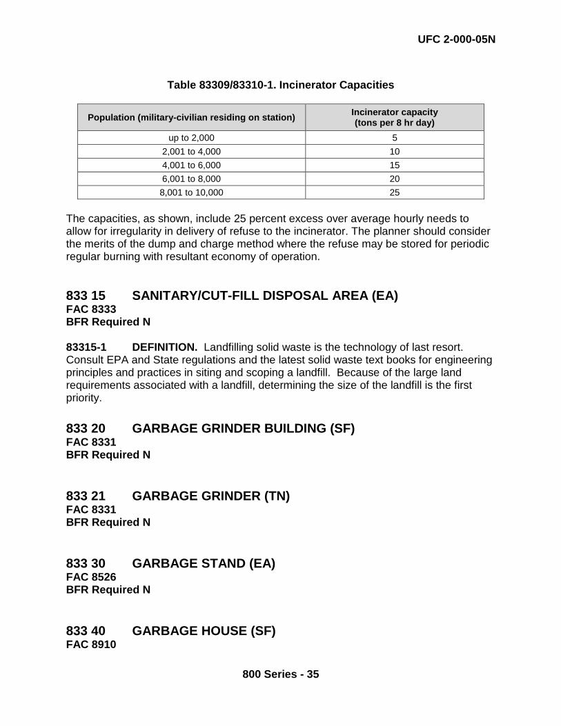
UFC 2-000-05N
800 Series - 35
Table 83309/83310-1. Incinerator Capacities
Population (military-civilian residing on station) Incinerator capacity (tons per 8 hr day)
up to 2,000 5 2,001 to 4,000 10 4,001 to 6,000 15 6,001 to 8,000 20 8,001 to 10,000 25
The capacities, as shown, include 25 percent excess over average hourly needs to allow for irregularity in delivery of refuse to the incinerator. The planner should consider the merits of the dump and charge method where the refuse may be stored for periodic regular burning with resultant economy of operation. 833 15 SANITARY/CUT-FILL DISPOSAL AREA (EA) FAC 8333 BFR Required N 83315-1 DEFINITION. Landfilling solid waste is the technology of last resort. Consult EPA and State regulations and the latest solid waste text books for engineering principles and practices in siting and scoping a landfill. Because of the large land requirements associated with a landfill, determining the size of the landfill is the first priority. 833 20 GARBAGE GRINDER BUILDING (SF) FAC 8331 BFR Required N 833 21 GARBAGE GRINDER (TN) FAC 8331 BFR Required N 833 30 GARBAGE STAND (EA) FAC 8526 BFR Required N 833 40 GARBAGE HOUSE (SF) FAC 8910
UFC 2-000-05N
800 Series - 36
BFR Required N 83320/83321/83330/83340-1 DEFINITIONS. No planning criteria for Category Codes 833 20 through 833 40 are currently available. Each facility requires individual justification. 840 WATER FACILITIES 840-1 DEFINITION. Water facilities at naval installations shall provide sufficient quantities of potable water for domestic and industrial use; purification of raw water from deep wells, lakes, and rivers; storage of water in bulk storage tanks or reservoirs; and distribution of water to demand areas. The location of the supply sources may be determined by topographic maps, soil maps, climate data, and geologic surveys. The selection of water sources must be consistent with economic considerations, such as gravity delivery if possible. Separate nonpotable water fire protective systems may be provided where applicable. Planning information is provided for the following facility groups:
• Code 841 Potable Water - Supply, Treatment, and Storage • Code 842 Water Distribution System - Potable • Code 843 Water - Fire Protection • Code 844 Water Supply/Storage – Nonpotable • Code 845 Water Distribution System – Nonpotable
841 POTABLE WATER - SUPPLY, TREATMENT, AND
STORAGE 841-1 DEFINITION Planning for the treatment of water will include, as applicable, screening, settling, coagulation and sedimentation, filtration, disinfection, softening, and aeration. The water treatment systems are normally planned in millions of gallons (MG) per day capacity and distribution is in linear feet (LF). The systems must be adequate to meet the domestic and industrial requirements and to provide fire protection if a separate fire protection system is not provided. If separate nonpotable water protective systems are not provided, the capacity of the water supply system will be determined by the fire flow demand (see Code 843). Planning requirements for water treatment facilities will be based on the results of an engineering survey and an economic analysis to determined sources of water versus commercial or municipal supply. For water treatment methods see MIL HDBK-1005/7.

UFC 2-000-05N
800 Series - 37
841 09 WATER TREATMENT FACILITY BUILDING (SF) FAC 8910 BFR Required N 84109-1 DEFINITION. This Category Code includes buildings associated with a Water Treatment Plant (841 10), Desalinization Plant (841 25), or Wells - Potable Water (841 50). 84109-2 PROPERTY RECORD CARD USAGE. Each building shall be included on a single property record card. The equipment contained within the building shall be shown a separate property record card. 841 10 WATER TREATMENT PLANT - POTABLE (KG) FAC 8412 BFR Required N 84110-1 DEFINITION. This Category Code includes the structures, equipment, and processes required to treat potable water. 84110-2 PROPERTY RECORD CARD USAGE. All the water treatment plant equipment; clear wells, preliminary treatment, coagulation flocculation, sedimentation, adsorption, filtration, chemical treatment and storage, disinfection, electrical, water and compressed air systems, controls, and communication, is included on a single property record card with a facility type code of 4. The Unit of Measure is installed capacity in thousands of gallons per day (KG). Use CCN 841-09 in conjunction with CCN 841-10 to capture the both the treatment plant and the associated building on separate property record cards. 841 15 NUCLEAR REACTOR WATER TREATMENT FACILITY (KG) FAC 8412 BFR Required N 84115-1 DEFINITION. No criteria for this facility are currently available. 841 20 WATER SUPPLY LINE (LF) FAC 8421 BFR Required N 84120-1 DEFINITION. The pipe that conveys water from source to point of treatment or to the point of consumption. A pressure main will be needed if the water is
UFC 2-000-05N
800 Series - 38
pumped. However, if topography permits, a gravity system is planned. A twin conduit may be used to insure uninterrupted water supply. The unit of measure is linear feet of each pipe. 84120-2 PROPERTY RECORD CARD USAGE. There may be multiple property record cards with facility type code of 4 for a single water supply system after the utilities Maximo team has divided the installation into service areas as part of the linear segmentation process. Each part of the water supply system that is considered a linear structure shall have its own property record card with a facility type code of 4. 841 25 DESALINIZATION PLANT (KG) FAC 8415 BFR Required N 84125-1 DEFINITION. A water treatment plant that utilizes a process, such as distillation, reverse osmosis, or electro dialysis, that removes dissolved mineral salts and other dissolved solids from water. The primary unit of measure is installed capacity of the plant in thousands of gallons per day (KG). 84125-2 PROPERTY RECORD CARD USAGE. All the equipment involved in the desalination process; clear wells, preliminary treatment, coagulation flocculation, sedimentation, adsorption, filtration, chemical treatment and storage, disinfection, electrical, water and compressed air systems, controls and communication, is included on a single property record card with a facility type code of 4. 841 30 STORAGE TANKS - ELEVATED, POTABLE (GA) FAC 8413 BFR Required N 841 40 STORAGE TANKS - GROUND LEVEL, POTABLE (GA) FAC 8413 BFR Required N 83130/84140-1 DEFINITION. Water storage tanks for potable water are elevated or ground-level structures used to store bulk quantities of potable water. Elevated tanks for potable water provide both storage and static pressure for the distribution system. Ground-level tanks accommodate peak demand requirements without affecting the capability of the source. The planning for potable water storage tanks will be based on the requirements determined by an engineering survey. These surveys will determine the capacities and pressures required for the water system. Elevated tanks will not be planned in the immediate vicinity of an airfield. Water uses which must be considered in estimating potable water requirements for shore installations are (a) domestic, (b) industrial, and (c) fire protection.
UFC 2-000-05N
800 Series - 39
84130/84140 – 2 PROPERTY RECORD CARD USAGE. Water storage tanks located at the water treatment facility that are part of the plant process are included with the water treatment facility (841 10) and are not classified as separate real property. Water storage tanks that are considered part of the distribution system shall be listed on individual property record cards with a facility type code of 3. The unit of measure is rated storage capacity of the tank in gallons (GA). 841 50 WATER WELLS - POTABLE (KG) FAC 8414 BFR Required N 84150-1 DEFINITION. Equipment that pumps water from underground sources to treatments plants or directly to distribution with minor treatment possibly injected. The building that houses the well equipment shall be listed on a separate property record card utilizing category code 841 09. The primary unit of measure is well capacity in thousands of gallons per day (KG) and the alternate unit of measure - installed capacity in gallons per minute (GM) shall both be included on the property record card. 84150-2 PROPERTY RECORD CARD USAGE - All equipment associated with a single well shall be shown on an individual property record card with a facility type code of 4. Each well shall be shown on a separate property record card. 841 51 RESERVOIR - POTABLE WATER (MG) FAC 8443 BFR Required N 84151-1 DEFINITION. An open body of water for the collection and storage of water used by a water treatment facility or water distribution system. The Unit of Measure is reservoir capacity in millions of gallons (MG) 84151-2 PROPERTY RECORD CARD USAGE – Each reservoir shall be shown on a separate property record card with a facility type code of 4. 841 52 WATER CATCHMENT STRUCTURE (GA) FAC 8442 BFR Required N 84152-1 DEFINITION. A man-made structure designed to capture or collect rainwater and used to produce potable water. The primary unit of measure is linear feet around the structure (LF). 84151-2 PROPERTY RECORD CARD USAGE – Each structure shall be shown on a separate property record card with a facility type code of 3.

UFC 2-000-05N
800 Series - 40
842 WATER DISTRIBUTION SYSTEM, POTABLE 84209/84210-1 DEFINITION. Potable water will be transmitted from a storage tank or a treatment plant to all station demand points through a pipeline. An engineering study of the pressures and quantities of water required at the demands points will serve as the basis for planning the sizes and lengths of pipe required for the water distribution pipelines. Planning for a potable water distribution pipeline will include requirements for piping, valves, pumps, connections, excavation, and backfilling. The pipeline shall be listed in linear feet (LF). Requirements will be determined by an engineering study. 842 09 WATER DISTRIBUTION BUILDING, POTABLE (SF) FAC 8910 BFR Required N 84209-1 DEFINITION. This Category Code includes buildings associated with the distribution of potable water, typically housing distribution pumps and equipment. 84209-2 PROPERTY RECORD CARD USAGE – Each building shall be included on a single property record card with a facility type code of 2. The equipment contained within the building shall be shown on a separate property record card using category code 842 15. 842 10 WATER DISTRIBUTION LINE, POTABLE (LF) FAC 8421 BFR Required N 84210-2 DEFINITION. All pipes that convey potable water from the treatment plant to the end user. The primary unit of measure is linear feet of pipe (LF). 84210-2 PROPERTY RECORD CARD USAGE. There may be multiple property record cards for a single water distribution system after the utilities Maximo team has divided the installation into service areas as part of the linear segmentation process. Each part of the water distribution system that is considered a linear structure shall have its own property record card with a facility type code of 4. 842 15 PUMP STATION - POTABLE WATER (KG) FAC 8422 BFR Required N 84215-1 DEFINITION. This category code will include the pump(s) and appurtenant piping, valves, and other mechanical and electrical equipment for pumping
UFC 2-000-05N
800 Series - 41
water in the potable water system. The primary unit of measure is installed pumping capacity of the station in thousands of gallons per day (KG) and the alternate unit of measure is the installed pumping capacity of the station in gallons per minute (GM) . 84215-2 PROPERTY RECORD CARD USAGE. All equipment in a single pump station is contained on one property record card with a facility type code of 4. 843 WATER, FIRE PROTECTION 843-1 DEFINITION. Fire protection requirements often dominate the plans of a water supply system. When the supply of fresh water is not adequate, salt water may be used. Since fire flow demands are usually greater than either the domestic or industrial demands, the capacity of the system will generally be determined by the fire flow demands. Fire flows are expressed in gallons per minute and are separate from the other water requirements. Normal fire flow demands are as follows: 843-1.1 Dwellings. The fire flow requirements for residential areas shall be as follows:
Individual and duplex units--1 story--500 gallons per minute Individual and duplex units--2 stories--750 gallons per minute Multifamily (3 or more) units--1 story--750 gallons per minute Multifamily (3 or more) units--2 stories --1,000 gallons per minute
843-1.2 Light and Ordinary Hazards. In both light and ordinary hazard areas, the fire flow requirements for both hose streams and automatic sprinkler systems shall be as indicated in the table below.

UFC 2-000-05N
800 Series - 42
Table 843-1
Fire Flow Requirements (Gallons Per Minute)
Height and Area (Sq Ft)
Unsprinkered Sprinklered Hose Streams Hose Streams
Sprinkler Demand
Total Fire
Resistive, N.C.
(Masonry)
Ordinary, and Heavy Timber
Frame, N.C. (All Metal)
Fire Resistive,
N.C. (Masonry) Ordinary, and Heavy
Timber
Frame, N.C. (All Metal)
Fire Resistive,
N.C. (Masonry) Ordinary, and Heavy
Timber
Frame, N.C. (All Metal)
1 Story 0-10,000 750 1,250 250 250 500 750 750 10,000-20,000 1,000 1,750 250 250 750 1,000 1,000 20,000-80,000 1,250 2,500 250 500 1,000 1,250 1,500 Multistory 0-10,000 1,000 2,000 250 500 500 750 1,000 10,000-20,000 1,250 2,500 250 500 750 750 1,250 20,000-80,000 1,750 3,000 300 750 1,000 1,500 1,750
Notes: 1. All one-story buildings above 20 feet in height shall be classified as multistory. 2. Flows for hose streams shall be provided at 20 psi residual pressure. 3. Sprinkler demand requirements shall be based on a residual pressure at grade to provide a minimum
pressure of 15 psi at the highest sprinkler. 4. In unsprinklered one-story buildings, less than 1,000 square feet ground floor area, hose streams
requirement of 500 gpm generally will be satisfactory.
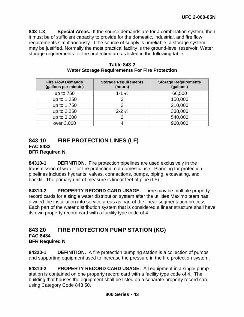
UFC 2-000-05N
800 Series - 43
843-1.3 Special Areas. If the source demands are for a combination system, then it must be of sufficient capacity to provide for the domestic, industrial, and fire flow requirements simultaneously. If the source of supply is unreliable, a storage system may be justified. Normally the most practical facility is the ground-level reservoir. Water storage requirements for fire protection are as listed in the following table:
Table 843-2
Water Storage Requirements For Fire Protection
Fire Flow Demands (gallons per minute)
Storage Requirements (hours)
Storage Requirements (gallons)
up to 750 1-1 ½ 66,500 up to 1,250 2 150,000 up to 1,750 2 210,000 up to 2,250 2-2 ½ 338,000 up to 3,000 3 540,000 over 3,000 4 960,000
843 10 FIRE PROTECTION LINES (LF) FAC 8432 BFR Required N 84310-1 DEFINITION. Fire protection pipelines are used exclusively in the transmission of water for fire protection, not domestic use. Planning for protection pipelines includes hydrants, valves, connections, pumps, piping, excavating, and backfill. The primary unit of measure is linear feet of pipe (LF). 84310-2 PROPERTY RECORD CARD USAGE. There may be multiple property record cards for a single water distribution system after the utilities Maximo team has divided the installation into service areas as part of the linear segmentation process. Each part of the water distribution system that is considered a linear structure shall have its own property record card with a facility type code of 4. 843 20 FIRE PROTECTION PUMP STATION (KG) FAC 8434 BFR Required N 84320-1 DEFINITION. A fire protection pumping station is a collection of pumps and supporting equipment used to increase the pressure in the fire protection system. 84310-2 PROPERTY RECORD CARD USAGE. All equipment in a single pump station is contained on one property record card with a facility type code of 4. The building that houses the equipment shall be listed on a separate property record card using Category Code 843 50.

UFC 2-000-05N
800 Series - 44
843 30 WATER STORAGE TANK - FIRE PROTECTION WATER (MG) FAC 8435 BFR Required N 84330-1 DEFINITION. Tanks that provide fire protection water storage to accommodate peak demand requirements. The primary unit of measure is tank capacity in millions of gallons (MG) and the alternate unit of measure is tank capacity in gallons (GA). 84330-2 PROPERTY RECORD CARD USAGE – Each tank shall be shown on a separate property record card with a facility type code of 3. 843 35 RESERVOIRS - FIRE PROTECTION WATER (MG) FAC 8433 BFR Required N 84335-1 DEFINITION. This Category Code is for a reservoir that has a capacity greater than or equal to one million gallons and typically provides a sufficient quantity of water in reserve to insure an uninterrupted flow for fire protection. The primary unit of measure is reservoir capacity in millions of gallons (MG). 84335-2 PROPERTY RECORD CARD USAGE – Each reservoir shall be shown on a separate property record card with a facility type code of 4. 843 40 WELLS - FIRE PROTECTION WATER (GM) FAC 8431 BFR Required N 84340-1 DEFINITION. This Category Code is for equipment that pumps water from underground sources to the fire protection system. The primary unit of measure is well capacity in gallons per minute (GM). The building that houses the well equipment shall be shown on a separate property record card utilizing Category Code 843 50. 84340-2 PROPERTY RECORD CARD USAGE – Each well shall be shown on a separate property record card with a facility type code of 4. 843 50 FIRE PROTECTION BUILDING (SF) FAC 8910 BFR Required N

UFC 2-000-05N
800 Series - 45
84350-1 DEFINITION. This Category Code includes buildings associated with the distribution of fire protection water, typically housing distribution pumps and equipment. 84350-2 PROPERTY RECORD CARD USAGE. Each building shall be included on a single property record card with a facility type code of 2. The equipment contained within the building shall be shown a separate property record card using Category Code 843 20. 844 WATER SUPPLY/STORAGE, NONPOTABLE WATER 844-1 DEFINITION The water from these facilities will be used primarily for industrial purposes or as an emergency supply should there be a failure of the principal source. When a requirement for nonpotable water source exists, firefighting water requirements usually will be combined with this group. Requirements for this facility group are similar to that for Category Group 841 and 843. The Category Group 844 contains the following individual codes: 844 10 WATER DISTRIBUTION BUILDING, NONPOTABLE WATER
(SF) FAC 8910 BFR Required N This Category Code contains assets that were previously listed in CCN 845 10. 84410-1 DEFINITION. This Category Code includes all buildings associated with the supply or distribution of nonpotable water, typically housing distribution pumps and equipment. All former property record cards with category code 845 10 should be listed using this category code number. 84410-2 PROPERTY RECORD CARD USAGE. Each building shall be included on a single property record card with a facility type code of 2.The equipment contained within the building shall be shown a separate property record card using category code 844 30 or 844 20. 844 20 WELLS - NONPOTABLE WATER (KG) FAC 8441 BFR Required N
UFC 2-000-05N
800 Series - 46
84420-1 DEFINITION. This Category Code includes equipment that pumps water from underground sources to a dedicated nonpotable water distribution system. The primary unit of measure is well capacity in thousands of gallons per day (KG). 84420-2 PROPERTY RECORD CARD USAGE. Each well and associated equipment shall be included on a single property record card with a facility type code of 4. The building that houses that houses the equipment shall be shown on a separate property record card using category code 844 10. 844 30 PUMP STATION - NONPOTABLE WATER (KG) FAC 8452 BFR Required N This Category code contains assets that were previously shown in 845 30. 84430-1 DEFINITION. This Category Code includes the collection of pumps and supporting equipment used to supply water to the nonpotable water system The primary unit of measure is the installed pumping capacity of the station in thousands of gallons per day (KG). 84430-2 PROPERTY RECORD CARD USAGE. The equipment in a single pump station is contained on a single property record card with a facility type code of 4. The building that houses the equipment shall be listed on a separate property record card using Category Code 844 10. 844 40 STORAGE TANKS - NONPOTABLE WATER (GA) FAC 8442 BFR Required N 84440-1 DEFINITION. This Category Code includes tanks that provide nonpotable water storage to accommodate peak demand requirements. 84440-2 PROPERTY RECORD CARD USAGE. Each tank shall be shown on a separate property record card with a facility type code of 3. 844 50 RESERVOIRS - NONPOTABLE WATER (MG) FAC 8443 BFR Required N 84450-1 DEFINITION. This Category Code includes a reservoir that has a capacity greater than or equal to one million gallons and typically provides a sufficient quantity of water in reserve to insure an uninterrupted flow for nonpotable water requirements. The primary unit of measure is reservoir capacity in millions of gallons (MG).
UFC 2-000-05N
800 Series - 47
84440-2 PROPERTY RECORD CARD USAGE. Each reservoir shall be shown on a separate property record card with a facility type code of 4. 845 WATER DISTRIBUTION SYSTEM - NONPOTABLE 845-1 DEFINITION. Facilities in this group support non-potable water supply systems and are similar to those described under Category Group 842. This group contains the following individual codes: 845 20 WATER DISTRIBUTION LINE, NONPOTABLE (LF) FAC 8451 BFR Required N 84520-1 DEFINITION. This Category Code includes all pipes that transmit water in a dedicated nonpotable water distribution system. The primary unit of measure is linear feet of pipe (LF). 84520-2 PROPERTY RECORD CARD USAGE. There may be multiple property record cards for a single nonpotable water distribution system after the utilities Maximo team has divided the installation into service areas as part of the linear segmentation process has been completed. Each part of the nonpotable water distribution system that is considered a linear structure shall have its own property record card with a facility type code of 4. 850 ROADS AND STREETS 851 10 ROADS (SY) FAC 8511 BFR Required N 851 11 ROADS, UNSURFACED (SY) FAC 8512 BFR Required N 851 15 LOAD/UNLOAD RAMP (SY) FAC 8928 BFR Required N
UFC 2-000-05N
800 Series - 48
851 20 VEHICULAR BRIDGES (SY) FAC 8513 BFR Required N 85110/85111/85115/85120-1 DEFINITION. Roads, streets, and bridges are generally planned to conform to the standards and practices of the American Association of State Highway Officials (AASHO), Bureau of Public Roads (BPR), and State and local governments. Planning is derived from the general development map of the station. See TM 5-822-2 / AFM 88-7 CHAP 5 for design criteria. 851 21 VEHICULAR PARKING, UNSURFACED (SY) FAC 8522 BFR Required Y 85121-1 DEFINITION. An unpaved surface for parking and/or staging private and/or government owned vehicles and equipment. The surface is usually graveled. Use the criteria under CCN 85210 Parking Area to develop parking requirements. 851 22 VEHICLE STAGING AREA (SY) FAC 8523 BFR Required Y 85122-1 DEFINITION. This category code represents surfaced areas for the temporary holding of vehicles and equipment awaiting deployment. It is not intended to be used for vehicle parking identified under CCN 85210 or un-surfaced parking and storage designated under CCN 85235 or CCN 85240. 851 23 TRAFFIC CONTROL SIGNALS (EA) FAC 8541 BFR Required N 85123-1 DEFINITION. Traffic control signals are devices used for directing pedestrian, vehicular or rail traffic by means of power-operated controls. Costs include signal devices, necessary supports, and electric power cables. 85123-2 PROPERTY RECORD CARD USAGE. Each (EA) is defined as one "intersection" as the unit of measure regardless of how many individual traffic signals or supports are in place at an intersection, with the understanding that in some cases the
UFC 2-000-05N
800 Series - 49
individual signal count may be low and in other cases it may be high - it averages out. Each intersection should be listed on a separate property record card. 851 25 VEHICULAR TUNNELS (LF) FAC 8514 BFR Required N 85125-1 DEFINITION. Vehicular tunnels are used for slope stabilization and automobile access in areas where steep slopes limit development and require innovative access solutions. These tunnels serve vehicular and pedestrian traffic as well as housing utility runs. They are also often used to combat soil erosion and protect facilities and personnel. 852 SIDEWALKS AND OTHER PAVEMENTS 852 10 PARKING AREA (SY) FAC 8521 BFR Required Y 85210-1 ORGANIZATIONAL VEHICLE PARKING. The paved and/or stabilized area within an organizational motor pool and parking lot, including space required for entrance and exit roads and aisles within the lot, will not exceed the following: 85210-1.1 Navy and Marine Corps installations (except Marine Corps installations with FMF Ground Units assigned). Forty square yards per unit for 75% of the equipment supported. The 40 square yards per unit takes into account the varied sizes and types of automotive, construction, and materials handling equipment to be parked. 85210-1.2 Marine Corps installations with FMF Ground Units assigned. Seventy-five square yards for each vehicle to be accommodated. The 75 SY will be reduced to 50 SY per vehicle if more than 50% of the vehicles to be accommodated have an overall length of 18 feet or less and a width of 6 1/2 feet or less (such as administrative-type vehicles). 85210-2 NON-ORGANIZATIONAL VEHICLE PARKING. Authorized parking spaces for non-organizational vehicles are listed in Table 852-10. The space allowance for each parking space is 35 square yards. This provides room for the parked vehicle and for normal interior lanes, entrances, and exits. Parking spaces for a facility not listed in the table shall be based on a special study of traffic analysis taking into account eligible vehicles, multiple utilization, time and space
UFC 2-000-05N
800 Series - 50
intervals, available public transportation, group-car riding and government-furnished transportation. For example, no planning factor has been established for parking space required for shipboard personnel while in homeport. Therefore a special study would be required to determine parking space needed to support this requirement. Such a study would take into consideration the number of ships which would be in the homeport at any one time and a derivation there from of the number of shipboard personnel requiring parking space. Where there is no direct experience, valid projections of available data may be made. Parking space for a listed facility, whether existing or planned, may be increased when justified by a special study or traffic analysis.

UFC 2-000-05N
800 Series - 51
Table 85210-1 Allowances for Non-Organizational Vehicle Parking
Facility Number of Parking Spaces
Administrative Buildings 70% of assigned personnel Bachelor Housing - Officers' Quarters 90% of capacity Bachelor Housing - Enlisted Quarters 70% of capacity Bakeries 38% of employees, largest shift Cafeterias, when not included in Community Shopping Center 15% of seating capacity
Chapels 15% of seating capacity Commissaries, when not included in Community Shopping Center See Category Code 740 23
Community Shopping Center 4% of population served Exchange Retail Store, when not included in Community Shopping Center
2% of military strength served
Family Housing 2 spaces per living unit Field House, combined with Football and Baseball facilities 1% of military strength
Fire Stations: 3-stall 7 spaces 7-stall 10 spaces Correctional Centers, Police Stations 30% of guard strength Temporary Quarters 90% of units Gymnasiums (if more than one on station, prorate total allowance) 1% of military strength
Laundries and Dry Cleaning Plants 38% of employees - largest shift Libraries: Central 1 space per each 500 SF of floor area Branch 2 spaces Maintenance Shops 38% of assigned personnel, largest shift Dental Clinic (either separate or as part of another medical facility 3 spaces per treatment room
Hospitals and Medical Clinics Use the following formula: (0.59 X1 + 0.19 X2) where
X1 = All personnel (staff) working in the facility on a continuous basis
X2 = Average daily outpatient/visitor load for the peak month. Factor X2 is excluded at troop clinics.
Reserve Training Centers 80% of reservists - largest drill period Dependent Schools: Without auditorium 2 spaces per classroom With auditorium 2 spaces per classroom plus 15% of auditorium seats
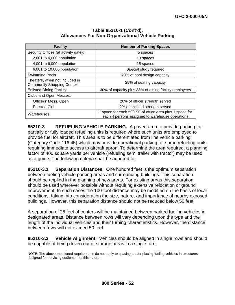
UFC 2-000-05N
800 Series - 52
Table 85210-1 (Cont’d). Allowances For Non-Organizational Vehicle Parking
Facility Number of Parking Spaces
Security Offices (at activity gate): 5 spaces 2,001 to 4,000 population 10 spaces 4,001 to 6,000 population 15 spaces 6,001 to 10,000 population Special study required Swimming Pools 20% of pool design capacity Theaters, when not included in Community Shopping Center 25% of seating capacity
Enlisted Dining Facility: 30% of capacity plus 38% of dining facility employees Clubs and Open Messes: Officers' Mess, Open 20% of officer strength served Enlisted Club 2% of enlisted strength served
Warehouses 1 space for each 500 SF of office area plus 1 space for each 4 persons assigned to warehouse operations
85210-3 REFUELING VEHICLE PARKING. A paved area to provide parking for partially or fully loaded refueling units is required where such units are employed to provide fuel for aircraft. This area is to be differentiated from line vehicle parking (Category Code 116 45) which may provide operational parking for some refueling units requiring immediate access to aircraft apron. To determine the area required, a planning factor of 400 square yards per vehicle (refueling semi trailer with tractor) may be used as a guide. The following criteria shall be adhered to: 85210-3.1 Separation Distances. One hundred feet is the optimum separation between fueling vehicle parking areas and surrounding buildings. This separation should be applied in the planning of new areas. For existing areas this separation should be used wherever possible without requiring extensive relocation or ground improvement. In such cases the 100-foot distance may be modified on the basis of local conditions, taking into consideration the size, nature, and importance of nearby exposed buildings. However, this separation distance should not be reduced below 50 feet. A separation of 25 feet of centers will be maintained between parked fueling vehicles in designated areas. Distance between rows will vary depending upon the type and the length of the individual vehicles and their turning characteristics. However, the distance between rows will not exceed 50 feet. 85210-3.2 Vehicle Alignment. Vehicles should be aligned in single rows and should be capable of being driven out of storage areas in a single turn. NOTE: The above-mentioned requirements do not apply to spacing and/or placing fueling vehicles in structures designed for servicing equipment of this nature.
UFC 2-000-05N
800 Series - 53
852 15 PARKING BUILDING, BICYCLE (SF) FAC 8531 BFR Required Y No criteria currently exist for this category code.
852 20 SIDEWALK (SY) FAC 8524 BFR Required N 852 30 PEDESTRIAN BRIDGES (SY) FAC 8525 BFR Required N 85220/85230-1 DEFINITION. Planning of sidewalks and pedestrian bridges is derived from the general development map of the activity. See TM 5-822-2 / AFM 88-7 CHAP 5 for design criteria. 852 35 OTHER PAVED AREAS NOT CODED IN THE 100 OR 400
SERIES (SY) FAC 8526 BFR Required N 85235-1 OTHER PAVED AREAS NOT CODED IN THE 100 OR 400 SERIES. This code is for miscellaneous vehicular pavements. No planning factors are available. 852 40 MISCELLANEOUS OPEN STORAGE OR LAYDOWN AREA
(SY) FAC 8526 BFR Required N 85240-1 MISCELLANEOUS OPEN STORAGE OR LAYDOWN AREA. This code is for open storage areas other than those used for general supply operations (Category Code 451 10). It includes Public Works Open Storage facilities. See Table 852 40 for allowances.
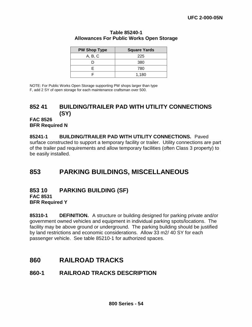
UFC 2-000-05N
800 Series - 54
Table 85240-1 Allowances For Public Works Open Storage
PW Shop Type Square Yards
A, B, C 225 D 380 E 780 F 1,180
NOTE: For Public Works Open Storage supporting PW shops larger than type F, add 2 SY of open storage for each maintenance craftsman over 500. 852 41 BUILDING/TRAILER PAD WITH UTILITY CONNECTIONS
(SY) FAC 8526 BFR Required N 85241-1 BUILDING/TRAILER PAD WITH UTILITY CONNECTIONS. Paved surface constructed to support a temporary facility or trailer. Utility connections are part of the trailer pad requirements and allow temporary facilities (often Class 3 property) to be easily installed. 853 PARKING BUILDINGS, MISCELLANEOUS 853 10 PARKING BUILDING (SF) FAC 8531 BFR Required Y 85310-1 DEFINITION. A structure or building designed for parking private and/or government owned vehicles and equipment in individual parking spots/locations. The facility may be above ground or underground. The parking building should be justified by land restrictions and economic considerations. Allow 33 m2/ 40 SY for each passenger vehicle. See table 85210-1 for authorized spaces. 860 RAILROAD TRACKS 860-1 RAILROAD TRACKS DESCRIPTION
UFC 2-000-05N
800 Series - 55
This category group covers all two-rail tracks including spurs, sidings, yards, turnouts, with accessories and appurtenances such as barricades. It includes trackage on ship repair facilities, marine railways and portal crane structures. 860 10 RAILROAD TRACKAGE (MI) FAC 8601 BFR Required N 86010-1 RAILROAD TRACKAGE. The planning of railroad trackage will be based on an economic analysis of the cost of truck haulage versus the cost of the proposed use of railroad facilities. Trackage is planned to connect the base with the common carrier and for holding and unloading freight cars as required. The amount of railroad trackage to be constructed by the government is determined by the proximity of the common carrier lines and the traffic volume. 860 20 EXPLOSIVE BARRICADE FOR SUSPECT TRUCKS AND
RAILROAD CARS (EA) FAC 1495 BFR Required N 86020-1 EXPLOSIVE BARRICADE FOR SUSPECT TRUCKS AND RAILROAD CARS. A suspect cargo site is for placing trucks and railcars containing ammunition or explosives that are suspected of being in a hazardous condition. These sites may be used jointly for railcars, motor vehicles and cargo containers. This facility should have effective barricades on three sides and sited in accordance with OP-5 Vol.1. Barricaded rail or truck spurs used for temporary holding of railcars and/or motor vehicles (non-suspect) may be captured under this function. This Category Code is for inventory purposes only, a BFR is not required. 860 30 RAILROAD BRIDGE AND TRESTLE (MI) FAC 8611 BFR Required N 860 40 CRANE TRACKAGE (MI) FAC 8601 BFR Required N 86030/86040-1 RAILROAD BRIDGE AND TRESTLE AND CRANE TRACKAGE. When planning track layouts, railroad trackage should be separated from portal crane trackage, because, apart from the similarity of the rails, portal crane trackage requirements are completely different from railroad trackage. Where separation is impossible, both cranes and rolling stock will utilize a common rail, and the other railroad trackage rail shall be placed inside the crane gauge.
UFC 2-000-05N
800 Series - 56
860 41 RAILROAD SCALEHOUSE (SF) FAC 8612 BFR Required N 86041-1 RAILROAD SCALEHOUSE. A railroad scalehouse is a facility designed to weigh rail cargo. Typically, tracks are laid to allow railcars to be pulled through the scalehouse. 870 GROUND IMPROVEMENT STRUCTURES 870-1 DEFINITION. This category group includes drainage and storm sewer systems, boundary fencing, gates, guard towers and shelters and other related facilities. 871 GROUNDS, DRAINAGE 871 10 STORM SEWER (LF) FAC 8321 BFR Required N 871/87110-1 DEFINITION. Storm sewers are components of a storm drainage system that collects the surface runoff water and conveys it to outlet points. Storm sewers are required at installations or areas where open drainage ditches would create a hazard to the operation of vehicles and aircraft or would prove hazardous to pedestrians. Storm sewers shall not be combined with sanitary sewers. See MIL HDBK-1005/3 for design information. 871 11 OIL/WATER SEPARATOR - RUNOFF WATER (KG) FAC 8313 BFR Required N 871 15 STORM WATER PUMPING STATION (EA) FAC 8452 BFR Required N 87111/87115-1 DEFINITION. Requirements for Category Codes 871 11 and 15 must be individually justified. No criteria are available.
UFC 2-000-05N
800 Series - 57
871 16 STORMWATER RETENTION PONDS (MG) FAC 8715 BFR Required N Criteria are currently being developed for this category code. 871 20 DRAINAGE DITCH (LF) FAC 8711 BFR Required N 87120-1 DEFINITION. Drainage ditches serve the same purpose as storm sewers. They are preferable to covered structures to minimize construction, to conserve materials, and to facilitate maintenance. Ditches should be planned to provide adequate depth to contain all runoff water anticipated from snow, ice, thaws, frozen ground, and severe rainfalls. In the planning of the drainage system, consideration should be given to the location of ditches to minimize the creation of hazards to vehicles or personnel. See MIL HDBK-1005/3 for technical information. 871 25 DAM (LF) FAC 8714 BFR Required N 87125-1 DEFINITION. A dam is an artificial or natural barrier usually constructed across a stream channel to impound water. Timber, rock, concrete, earth, steel or a combination of these materials may be used to build the dam. Dams must have spillway systems to safely convey normal stream and flood flows over, around, or through the dam. Spillways are commonly constructed of non-erosive materials such as concrete. Dams should also have a drain or other water-withdrawal facility to control the water level and to lower water levels for normal maintenance and emergency purposes. 87125-2 Dimensions and Capacity: A dam is at least six feet in height, measured vertically from top of barrier to elevation of lower downstream toe, and has an impounding capacity greater than 50 acre-feet; or is at least 25 feet in height, and has an impounding capacity greater than 15 acre-feet. Toe of Dam: The junction of the downstream face of a dam with the natural ground surface. This is also referred to as the downstream toe. 87125-3 Requirements for a new dam must be individually justified by an engineering study. When planning for this category code, consult with: NAVFAC Engineering Service Center, Washington, DC Office: CIOFP4 Phone: (202) 433-5516
UFC 2-000-05N
800 Series - 58
871 26 LEVEE AND/OR DIKE (LF) FAC 8714 BFR Required N 87126-1 DEFINITION. A levee is a type of dam that runs along the banks of a river or canal. Levees reinforce the banks and help prevent flooding. By confining the flow, levees can also increase the speed of the water. Levees can be natural or man-made. A natural levee is formed when sediment settles on the river bank, raising the level of the land around the river. To construct a man-made levee, workers pile dirt or concrete along the river banks, creating an embankment. This embankment is flat at the top, and slopes at an angle down to the water. For added strength, sandbags are sometimes placed over dirt embankments. 871 30 IRRIGATION FACILITY (LF) FAC 8451 BFR Required N 871 35 RETAINING WALL (LF) FAC 8712 BFR Required N 871 45 DREDGED SPOIL HANDLING FACILITY (GM) FAC 8714 BFR Required N 87130/87135/87145-1 DEFINITION. Requirements for Category Codes 871 30 through 45 must be individually justified. No criteria are available. 872 GROUNDS FENCING, GATES AND GUARD
TOWERS 872-1 DEFINITION This basic category provides boundary security in the form of fencing, walls, gates, watch towers, guard walks, and guard shelters. The type and amount of security planned is a function of the security classification required, and the economical utilization of security guards. Refer to MIL-HDBK-1013/1A, “Design Guidelines for
UFC 2-000-05N
800 Series - 59
Physical Security of Facilities” and MIL-HDBK-1013/10 “Design Guidelines for Security Fencing, Gates, Barriers, and Guard Facilities” for guidance in the selection and design of these facilities. 872 10 STATION SECURITY AND PERIMETER FENCING AND
WALLS (LF) FAC 8721 BFR Required N 87210-1 DEFINITION. Security fencing and walls define the limits of security areas and facilitate the effective and economical use of security personnel. Fencing is planned on the basis of a study of the security classification requirements of the installation. The permanency of the installation, availability of materials, presence of natural aids to security, guard personnel, security hazards, and problems and degree of security required, must be considered in all fence construction. Security fencing is generally of the type known as chain link or cyclone, or under certain conditions it may be barbed wire. Fences should be 50 to 150 feet from buildings or critical supplies to be protected. There should be at least 20 feet between perimeter fences and structures, parking areas, or natural features outside the fenced area which could offer concealment or assistance to unauthorized access to area protected. When this is not possible, perimeter fencing should be increased in height or otherwise designed to compensate for the proximity of aids to concealment or access. . See Table 87210-1 for appropriate applications and characteristics of fences. 87210-1.1 Standard Security Fencing. The average standard security fence of the so-called man proof type is the 7-foot cyclone, chain link fence with 1-1/2 foot outriggers mounting 3 barbed wire strands at 45 degrees, increasing the overall height of the fence to 8 feet. 87210-1.2 Barbed Wire. There are instances such as in isolated air stations, where three strand barbed wire cattle fence will suffice around the entire perimeter of the station, augmented by standard security fencing of critical areas, if such exist and can be adequately patrolled. 87210-1.3 Walls. Where walls, floors, and roofs serve as barriers, they should be constructed and arranged to provide uniform protection equivalent to that provided by chain link fencing as specified.
Table 87210-1 Applications And General Characteristics Of Fences
Application Location or Special Requirement Suitable Type
Height Feet Inches
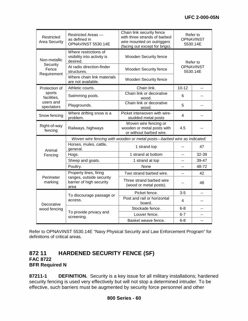
UFC 2-000-05N
800 Series - 60
Restricted Area Security
Restricted Areas — as defined in OPNAVINST 5530.14E
Chain link security fence with three strands of barbed wire mounted on outriggers (facing out except for brigs).
Refer to OPNAVINST
5530.14E
Non-metallic Security Fence
Requirement
Where restrictions of visibility into activity is desired.
Wooden Security fence Refer to
OPNAVINST 5530.14E
At radio direction-finder structures. Wooden Security fence
Where chain link materials are not available. Wooden Security fence
Protection of sports
facilities, users and spectators
Athletic courts. Chain link. 10-12 --
Swimming pools. Chain link or decorative wood. 6 --
Playgrounds. Chain link or decorative wood. 5 --
Snow fencing Where drifting snow is a problem.
Picket interwoven with wire-studded metal posts 4 --
Right-of-way fencing Railways, highways
Woven wire fencing or wooden or metal posts with
or without barbed wire. 4.5 --
Animal Fencing
Woven wire fencing with wooden or metal posts—barbed wire as indicated: Horses, mules, cattle, general. 1 strand top -- 47
Hogs. 1 strand at bottom -- 32-39 Sheep and goats. 1 strand at top -- 39-47 Poultry. None -- 48-72
Perimeter marking
Property lines, firing ranges, outside security barrier of high security area
Two strand barbed wire. -- 42
Three strand barbed wire (wood or metal posts). -- 48
Decorative wood fencing
To discourage passage or access.
Picket fence. 3-5 -- Post and rail or horizontal
board. 4 --
To provide privacy and screening.
Stockade fence. 6-8 -- Louver fence. 6-7 --
Basket weave fence. 6-8 -- Refer to OPNAVINST 5530.14E “Navy Physical Security and Law Enforcement Program” for definitions of critical areas. 872 11 HARDENED SECURITY FENCE (SF) FAC 8722 BFR Required N 87211-1 DEFINITION. Security is a key issue for all military installations; hardened security fencing is used very effectively but will not stop a determined intruder. To be effective, such barriers must be augmented by security force personnel and other
UFC 2-000-05N
800 Series - 61
means of protection, detection, delay, and assessment. Security fences are used primarily to:
a) Define the perimeter of a restricted area. b) Provide a physical and psychological deterrent to entry while serving notice
that entry is not freely permitted. c) Prevent accidental entry. d) Optimize security force operations. e) Enhance detection and apprehension of intruders. f) Channel and control the flow of personnel and vehicles through designated
portals. 87211-2 Prior to making decisions to employ security fencing, perform a thorough risk and threat analysis to determine the degree of physical security required. As indicated in Chapter 2 of Chief of Naval Operations Instruction (OPNAVINST) 5530.14E “Navy Physical Security and Law Enforcement Program”, extensive and costly security measures may be justified in certain cases to protect certain assets of security interest; however, ultimately the commanding officer of an activity is responsible for complying with established security requirements while at the same time working to achieve economy. To achieve this objective, higher echelon security requirements must be clearly understood. Additionally, evaluate the relative criticality and vulnerability of the security interest in relation to a ranking of potential threats, and calculate the specific level of security to ensure the best possible protection for that threat level in a cost-effective manner. Only after the above preliminary factors are addressed can a proper design be initiated. See MIL-HDBK-1013/1A, “Design Guidelines for Physical Security of Facilities”, for guidance and more detailed procedures which may be helpful in the decision process.
872 15 INTERIOR FENCING (NOT CODED IN 872 10) (LF) FAC 8721 BFR Required N This Category Code is for inventory purposes only, a BFR is not required. 872 20 GUARD AND WATCH TOWERS (EA) FAC 1499 BFR Required N 87220-1 DEFINITION. Where authorized, guard or watchtowers should be constructed at locations that will provide the best observation of security areas. The general building of guard towers at other than correctional facilities and certain special weapons projects is not presently considered appropriate. Each local security situation should be solved on its own merits.
UFC 2-000-05N
800 Series - 62
872 30 MECHANICAL SECURITY BARRICADE (EA) FAC 1458 BFR Required N 87230-1 DEFINITION. Mechanically operated barricade consisting of pop-up bollards, rising road plates, or wedges designed to control vehicle or other traffic. Drop arm barriers found at gates or rail road crossings and floating barrier systems around ships do not meet the definition of a mechanical security barricade and are not included. Costs include barrier installation, remote controls, safety loops, traffic arm, and traffic lights. CCTV, cameras, and alarms are considered equipment and are not included. 87230-2 PROPERTY RECORD CARD USAGE. EA is defined as a single barricade blocking a lane of traffic. A lane may have two barricades, one inside the gate entrance and one outside the gate entrance, therefore the count for that lane would be 2 (EA). 880 FIRE AND OTHER ALARM SYSTEMS 880-1 FIRE AND OTHER ALARM SYSTEMS This basic category includes separate integral signal systems such as fire alarm, watch reporting, and security. Telephone reporting systems are planned with telephone systems (see Code 130). 880 10 FIRE ALARM SYSTEM (MI) FAC 1351 BFR Required N 88010-1 FIRE ALARM SYSTEM. Fire alarm systems are of two general types: exterior systems and interior systems. Exterior systems normally have alarm initiating devices outside buildings, but may have components within buildings. Interior systems service a single building or group of buildings and may be connected to an exterior system. 88010-1.1 Exterior Fire Reporting Facilities. Exterior fire reporting systems of either telegraphic radio or supervised telephonic types are authorized for installation in built-up areas at military installations. The type of system selected for use shall be established on the basis of dependability, initial cost, and ability to maintain the system in operating condition. Extension of fire reporting systems will require consideration of compatibility with existing equipment. Fire reporting facilities will not normally be provided at isolated small areas, ammunition and ordnance storage, and similar restricted areas where personnel are not generally present to detect fires.
UFC 2-000-05N
800 Series - 63
88010-1.2 Interior Fire Reporting Facilities 88010-1.2.1 Automatic Fire Alarm Systems. Automatic fire detection and alarm systems are authorized for installation in:
1. Buildings, for protection of life, or in isolated and/or important facilities where automatic sprinkler protection would normally be provided but is not economically or technically feasible.
2. Combustible buildings used for the confinement of military prisoners where automatic sprinklers, normally provided, cannot be made available.
3. Combustible buildings of hospital groups and specific areas of noncombustible buildings of hospital groups, where automatic sprinklers are not provided.
4. One and two-story combustible dormitory-type living quarters, including bachelor officers' quarters, guesthouses, nurses' quarters, civilian dormitories, and similar buildings used for sleeping purposes.
88010-1.2.2 Manual Fire Alarm Systems. Manual fire and evacuation alarms are authorized for installation in:
1. Barracks, dormitories, bachelor officers' quarters and similar sleeping quarters involving 20 or more persons not otherwise provided with automatic fire detection alarms.
2. Combustible buildings used for confinement of military prisoners, not otherwise provided with automatic sprinkler or automatic fire detection systems.
3. Buildings involving personnel occupancy such as administration, clubs, schools, classrooms, hospitals, laboratories, industrial and similar structures. Normally, such buildings having occupancy of 20 or more persons will be provided with this type of alarm system.
880 20 WATCH REPORTING SYSTEM (MI) FAC 1351 BFR Required N 88020-1 WATCH REPORTING SYSTEM. A watch reporting system provides a method for the automatic and non-automatic detection of fire and for security protection (Intrusion Detection System) throughout designated areas, buildings, and structures. The watch reporting system provides local alarms and central station alarms to building occupants and to station security and firefighting personnel. Watch reporting systems are planned on the basis of engineering surveys to determine the degree of fire protection and security required.
UFC 2-000-05N
800 Series - 64
880 30 BASE ALERT SYSTEMS (MI) FAC 1351 BFR Required N 88030-1 BASE ALERT SYSTEMS. Base alert systems shall be planned for all Navy installations. The system may alert base personnel to air raids, chemical/biological attacks or any other type of terrorist attack. Horns of high-power type may be used as signal devices. Their locations shall be coordinated with structures and buildings to spread audible signals evenly and with enough intensity to be heard over a whole area or activity. 880 40 AIR CRASH/ALERT (MI) FAC 1351 BFR Required N 88040-1 AIR CRASH/ALERT. No planning criteria are currently available. 890 MISCELLANEOUS UTILITIES 890 09 MISCELLANEOUS UTILITY BUILDING (SF) FAC 8910 BFR Required N 89009-1 DEFINITION. This Category Code is used for structures associated with public works utilities shops and other miscellaneous utility buildings. If a utility building cannot be classified under one of the other utility type buildings, this Category Code should be used. Specific the general use of the building in the facility name field. 890 10 ACETYLENE PLANT (EA) FAC 8921 BFR Required N 890 11 ACETYLENE DISTRIBUTION SYSTEM (LF) FAC 8930 BFR Required N 89010/89011-1 DEFINITION. Generally the generation of acetylene is a function of private industry. Where commercial sources are nonexistent or of poor quality, a generating plant may be built. The quantity of acetylene required and the siting of an
UFC 2-000-05N
800 Series - 65
acetylene plant within safety criteria are determined by an engineering study. A typical acetylene generator building has an approximate gross area of 2,200 square feet. 890 15 NITROGEN PLANT (EA) FAC 8921 BFR Required N 89015-1 DEFINITION. A nitrogen plant is required for the provision of large quantities of nitrogen for special applications. Nitrogen is used where an inert gas is required. It prevents oxidation in welding and soldering. It prevents spoilage of perishable supplies by displacing air in special storage facilities. Nitrogen is also used in the quick freezing of food. Nitrogen is provided by commercial sources where available. A requirement for a nitrogen plant shall be determined by a special study. Nitrogen and oxygen are by-products of each other so preliminary guidance may be taken from oxygen plant criteria (Category Code 141 87 Liquid Oxygen Facility and 890 30 Industrial Oxygen Plant). 890 18 UTILITY VAULT (EA) FAC 8927 BFR Required N 89018-1 DEFINITION. A utility vault is an enclosed structure generally made of concrete that contains utility equipment, connections and/or lines. A utility vault is typically an underground structure. This category code is for inventory purposes only. 890 20 COMPRESSED AIR PLANT (EA) FAC 8921 BFR Required N 890 21 COMPRESSED AIR DISTRIBUTION SYSTEM (LF) FAC 8930 BFR Required N 89020/89021-1 DEFINITION. Compressed air is used by the Navy in numerous applications, such as for pneumatic tools, laundry equipment, instrumentation and control equipment, and in hospitals and laboratories. If the requirement is sufficiently large at an installation, a central compressed air plant and distribution system should be installed. A careful analysis of all compressed air operating requirements is necessary to determine the capacity and pressure of the distribution system. Usually, compressed air is distributed at 100 to 125 psig from a central system for general purpose needs. Special, high-pressure systems are required for ordnance plants, ammunition depots, catapults, and submarine facilities.
UFC 2-000-05N
800 Series - 66
89020/89021-1 PROPERTY RECORD CARD USAGE. There may be multiple property record cards for a single compressed air distribution system after the linear segmentation process has been completed. Each part of the compressed air distribution system that is considered a linear structure shall have its own property record card. There will be multiple linear segments within a linear structure and they will be recorded in GIS. They do not need to be shown on the property record card. All property record cards for a single network are related by a RPNUID. 890 25 CARBON DIOXIDE PLANT (EA) FAC 8921 BFR Required N 89025-1 DEFINITION. A carbon dioxide plant at a naval activity provides space for the storage and transfer of carbon dioxide. The space contains a storage tank and a distribution system used for refilling carbon dioxide fire extinguishers. The space required will approximate 1,200 to 2,000 square feet. 890 27 ICE-MAKING PLANT (TN) FAC 7322 BFR Required N 89027-1 DEFINITION. No planning criteria are currently available. 890 30 INDUSTRIAL OXYGEN PLANT (EA) FAC 8921 BFR Required N 890 31 OXYGEN DISTRIBUTION SYSTEM (LF) FAC 8930 BFR Required N 89030/89031-1 DEFINITION. Industrial oxygen is obtained from private industry where feasible. Where oxygen must be produced, it is obtained by breakdown of air into oxygen and nitrogen. Nitrogen is a by-product. Breathing oxygen is handled separately from industrial oxygen because of more stringent purity requirements. See Category Code 141 87 Liquid Oxygen Facilities for breathing oxygen. 890 45 VALVE HOUSE OR OTHER SHED/SHELTER (SF) FAC 8910 BFR Required N
UFC 2-000-05N
800 Series - 67
89045-1 DEFINITION. This Category Code is used for any structure used for housing valves or other utility equipment that is not contained in any other CCN. 890 46 UTILITY TUNNEL (LF) FAC 8931 BFR Required N 89046-1 DEFINITION. This Category Code is used for a tunnel in which utility systems are routed. There may be multiple utility systems in a single tunnel network. 890 50 ICS COMMUNICATION LINES (MI) FAC 1351 BFR Required N Revised August 2015 89050-1 DEFINITION. This category code is used for Industrial Control System (ICS) communication lines. By definition, wireless ICS communications are not addressed or inventoried in iNFADS. 89050-2 PROPERTY RECORD CARD USAGE. Industrial Control System communication lines shall be listed on a single property record card. Large installations with multiple geographic service areas will require a property record card for each geographic service area containing ICS communication lines. 890 51 ICS MONITORING STATION (SF) FAC 8910 BFR Required: Y Created August 2015 89051-1 BACKGROUND. The Navy and Marine Corps Smart Grid Program aggregates building energy information, utility information, and operational technologies (i.e. Industrial Control System (ICS)) in order to reduce facility maintenance costs, reduce energy consumption, and support mission assurance. Centralization of an ICS requires the establishment of regional and installation level ICS Monitoring Stations where various building and utility systems can be monitored and controlled.
89051-2 DEFINITION. The ICS Monitoring Station is the utility support facility that houses the operational components of the ICS as well as the personnel that operate the system. The ICS Monitoring Station is a component of the ICS and makes the ICS complete and usable. An ICS Monitoring Station should not be confused with a National Operations Center (NOC), Regional Operations Center (ROC) or Emergency Operations Center (EOC).
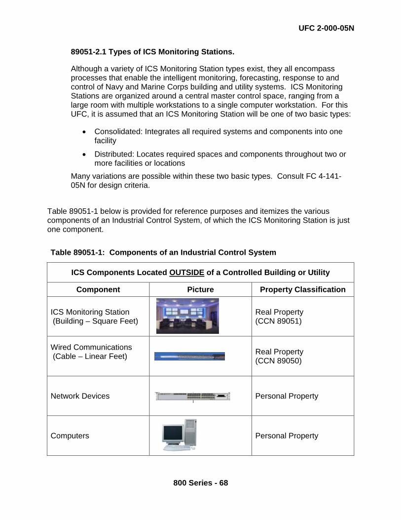
UFC 2-000-05N
800 Series - 68
89051-2.1 Types of ICS Monitoring Stations.
Although a variety of ICS Monitoring Station types exist, they all encompass processes that enable the intelligent monitoring, forecasting, response to and control of Navy and Marine Corps building and utility systems. ICS Monitoring Stations are organized around a central master control space, ranging from a large room with multiple workstations to a single computer workstation. For this UFC, it is assumed that an ICS Monitoring Station will be one of two basic types:
• Consolidated: Integrates all required systems and components into one facility
• Distributed: Locates required spaces and components throughout two or more facilities or locations
Many variations are possible within these two basic types. Consult FC 4-141-05N for design criteria.
Table 89051-1 below is provided for reference purposes and itemizes the various components of an Industrial Control System, of which the ICS Monitoring Station is just one component.
Table 89051-1: Components of an Industrial Control System
ICS Components Located OUTSIDE of a Controlled Building or Utility
Component Picture Property Classification
ICS Monitoring Station (Building – Square Feet)
Real Property
(CCN 89051)
Wired Communications (Cable – Linear Feet)
Real Property
(CCN 89050)
Network Devices
Personal Property
Computers
Personal Property

UFC 2-000-05N
800 Series - 69
Software
Personal Property
Wireless Communications
Personal Property

UFC 2-000-05N
800 Series - 70
Table 89051-2: Components of an Industrial Control System
ICS Components Located INSIDE of a Controlled Building or Utility
Component Picture Property Classification
Supervisory Controllers
Real Property Installed Equipment
Network Devices
Personal Property
Supervisory Control and Data Acquisition (SCADA)
Real Property Installed Equipment
Direct Digital Control (DDC)
Real Property Installed Equipment
Advanced Metering Infrastructure (AMI) Meters
Real Property Installed Equipment
Sensors
Real Property Installed Equipment
Actuators
Real Property Installed Equipment
Cameras
Personal Property
Protection
Personal Property
UFC 2-000-05N
800 Series - 71
89051-3 SPACE TYPES AND PLANNING FACTORS
89051-3.1. Office and General Purpose Spaces.
89051-3.1.1. Private Offices. Allocate 120 NSF/PN per Private Office required. 89051-3.1.2. Open Offices. Allocate 64 NSF/PN per Open Office required.
89051-3.1.3. Administrative Support Space. This space supports the administrative functions and includes all such functions not included in personal office space. It includes space for working office storage, copiers, working files, printers, scanners, shredders, safes, and facsimile machines. Allocate 8 NSF/PN for all personnel in office spaces. 89051-3.1.4. Conference Room. For a Regional ICS Monitoring Station with up to 24 total personnel, provide one conference room at 400 NSF. For an Installation Level ICS Monitoring Station conference room (if required), allocate 200 NSF. 89051-3.1.5. Reception Area. A Reception Area is used for receiving visitors and controlling access to ICS Monitoring Station spaces and are justified only for large, consolidated ICS Monitoring Stations. Allocate 64 NSF for a reception desk and include space for up to 5 visitors @ 20 NSF/visitor.
89051-3.1.6. Circulation. This is space used to provide for circulation in and around the administrative space types above. Apply an Office and Assembly Space Circulation multiplier of 10% to the NSF allocation.
89051-3.2. Special Purpose Spaces
89051-3.2.1. ICS Integration and Application Space. ICS Integration and Application Space is used for training and work bench space, but it is not continuously manned. Allocate 200 NSF for ICS Integration and Application Space. 89051-3.2.2. IT Storage Space. IT Storage Space is used for storage of IT equipment and supplies. Allocate 150 NSF for IT Storage Space. 89051-3.2.3. Master Control Room. A Master Control Room (MCR) is the central monitoring and action function within the ICS Monitoring Station. Sizing of the MCR is based on the number of operators and
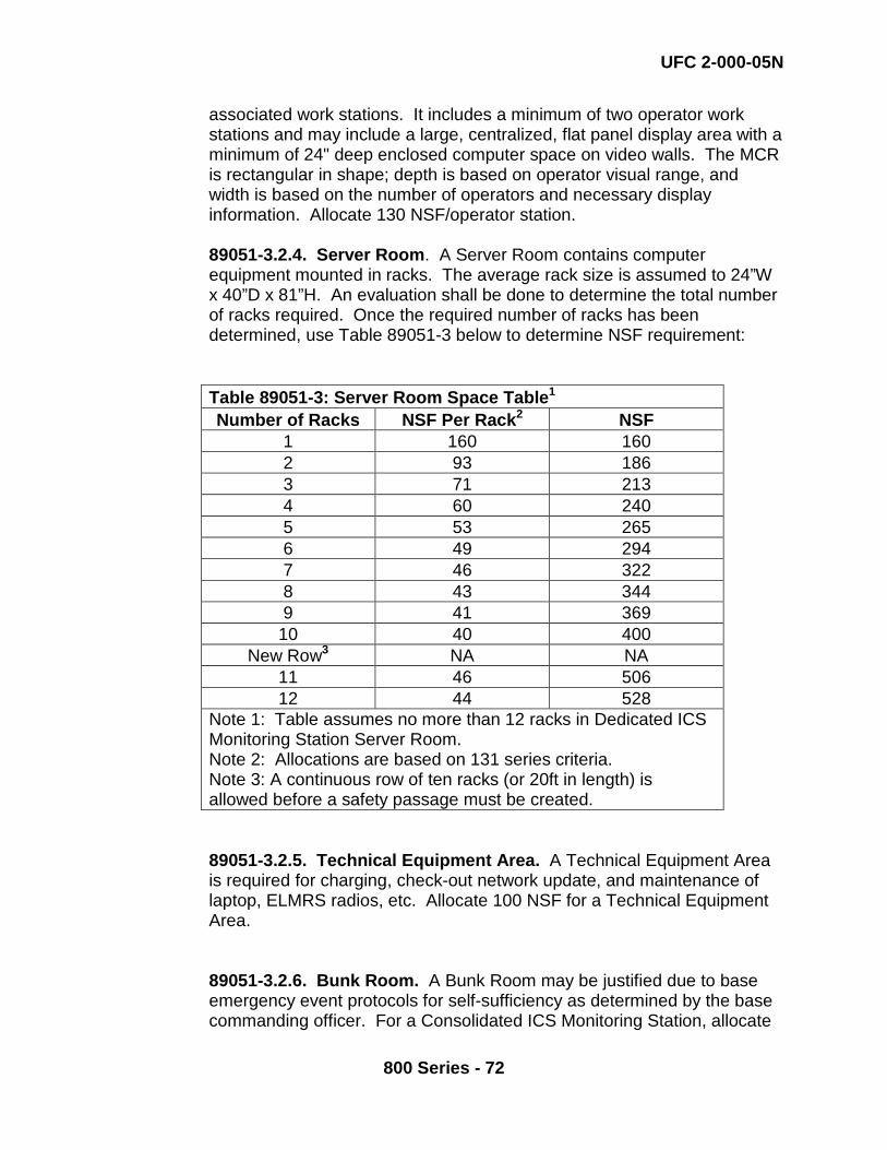
UFC 2-000-05N
800 Series - 72
associated work stations. It includes a minimum of two operator work stations and may include a large, centralized, flat panel display area with a minimum of 24" deep enclosed computer space on video walls. The MCR is rectangular in shape; depth is based on operator visual range, and width is based on the number of operators and necessary display information. Allocate 130 NSF/operator station. 89051-3.2.4. Server Room. A Server Room contains computer equipment mounted in racks. The average rack size is assumed to 24”W x 40”D x 81”H. An evaluation shall be done to determine the total number of racks required. Once the required number of racks has been determined, use Table 89051-3 below to determine NSF requirement: Table 89051-3: Server Room Space Table1 Number of Racks NSF Per Rack2 NSF
1 160 160 2 93 186 3 71 213 4 60 240 5 53 265 6 49 294 7 46 322 8 43 344 9 41 369
10 40 400 New Row3 NA NA
11 46 506 12 44 528
Note 1: Table assumes no more than 12 racks in Dedicated ICS Monitoring Station Server Room. Note 2: Allocations are based on 131 series criteria. Note 3: A continuous row of ten racks (or 20ft in length) is allowed before a safety passage must be created.
89051-3.2.5. Technical Equipment Area. A Technical Equipment Area is required for charging, check-out network update, and maintenance of laptop, ELMRS radios, etc. Allocate 100 NSF for a Technical Equipment Area. 89051-3.2.6. Bunk Room. A Bunk Room may be justified due to base emergency event protocols for self-sufficiency as determined by the base commanding officer. For a Consolidated ICS Monitoring Station, allocate

UFC 2-000-05N
800 Series - 73
130 NSF for Bunk Room. 89051-3.2.7. Break Room. A Break Room is justified for all ICS monitoring stations unless a kitchen is justified in its place. Allocate 20 NSF/PN based on the number of people in MCR during the largest shift. 89051-3.2.8. Kitchen. A Kitchen may be justified due to base emergency event protocols for self-sufficiency as determined by the base commanding officer. Allocate 30 NSF/PN based on the number of people in MCR during the largest shift. . 89051-3.2.9. Locker Room. A Locker Room area may be justified based on permanent staff within the MCR. Allocate 10 NSF/Locker/PN based on the number of people in MCR during the largest shift. 89051-3.2.10. Shower Room. A Shower Room may be justified due to base emergency event protocols for self-sufficiency as determined by the base commanding officer. Allocate 20 NSF/Shower when required up to a maximum of two showers. 89051-3.2.11. Special Purpose Space Circulation. This space used for circulation within the Special Purpose Spaces. Apply a Special Purpose Space Circulation factor of 10% to the NSF allocated.
89051-3.2.12. Electrical, Mechanical and Rest Rooms and other common areas are included within the Net to Gross factor. For an ICS Monitoring Station, apply an overall Net to Gross Factor of 1.35.
Table 89051-4: Planning Factors for ICS Monitoring Station Space Type NSF Factor/Multiplier Office and Assembly Space: Private Offices 120 NSF/person Open Offices 64 NSF/person Administrative Support Space 8 NSF/PN for office space
personnel. Conference Room at Installation Level ICSMS 200 NSF Conference Room at Regional Level ICSMS 400 NSF Reception Area at Regional Level ICSMS 164 NSF Office and Assembly Space Circulation Multiplier 10% Special Purpose Space: ICS Integration and Application Space 200 NSF IT Storage Space 150 NSF Master Control Room 130 NSF/Operator Work Station Reception Area 164 NSF

UFC 2-000-05N
800 Series - 74
Server Room See Table 89051-4 Technical Equipment Area 100 NSF Bunk Room (for emergency events) 130 NSF Break Room (apply in lieu of Kitchen) 20 NSF/PN Kitchen (for emergency events) 30 NSF/PN justified Locker Room 10 NSF/Locker/PN justified Shower Room (for emergency events) 20 NSF/Shower Circulation Multiplier 10% ICS Monitoring Station NTG Factor: 1.35
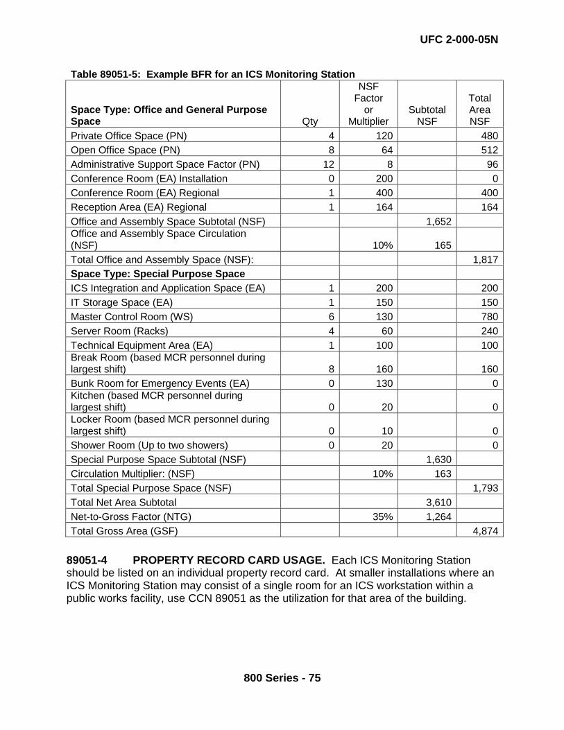
UFC 2-000-05N
800 Series - 75
Table 89051-5: Example BFR for an ICS Monitoring Station
Space Type: Office and General Purpose Space Qty
NSF Factor
or Multiplier
Subtotal NSF
Total Area NSF
Private Office Space (PN) 4 120 480 Open Office Space (PN) 8 64 512 Administrative Support Space Factor (PN) 12 8 96 Conference Room (EA) Installation 0 200 0 Conference Room (EA) Regional 1 400 400 Reception Area (EA) Regional 1 164 164 Office and Assembly Space Subtotal (NSF) 1,652 Office and Assembly Space Circulation (NSF) 10% 165 Total Office and Assembly Space (NSF): 1,817 Space Type: Special Purpose Space ICS Integration and Application Space (EA) 1 200 200 IT Storage Space (EA) 1 150 150 Master Control Room (WS) 6 130 780 Server Room (Racks) 4 60 240 Technical Equipment Area (EA) 1 100 100 Break Room (based MCR personnel during largest shift) 8 160 160 Bunk Room for Emergency Events (EA) 0 130 0 Kitchen (based MCR personnel during largest shift) 0 20 0 Locker Room (based MCR personnel during largest shift) 0 10 0 Shower Room (Up to two showers) 0 20 0 Special Purpose Space Subtotal (NSF) 1,630 Circulation Multiplier: (NSF) 10% 163 Total Special Purpose Space (NSF) 1,793 Total Net Area Subtotal 3,610 Net-to-Gross Factor (NTG) 35% 1,264 Total Gross Area (GSF) 4,874
89051-4 PROPERTY RECORD CARD USAGE. Each ICS Monitoring Station should be listed on an individual property record card. At smaller installations where an ICS Monitoring Station may consist of a single room for an ICS workstation within a public works facility, use CCN 89051 as the utilization for that area of the building.
UFC 2-000-05N
800 Series - 76
890 56 WEIGHTING FACILITY (EA) FAC 8923 BFR Required N No criteria are currently available for this Category Code. 890 77 STORAGE FOR UTILITY SYSTEMS (READY ISSUE/SHOP
STORES/MISC.) (SF) FAC 8910 BFR Required Y 89077-1 DEFINITION. This facility provides covered storage for large items and materials required for the maintenance of base utility systems to include, but not limited to: spare pole mounted transformers, power cable spools, and large diameter piping. It is independent of the facilities required for the storage of items and materials required for the maintenance of station buildings and grounds (use Category Code 219 77). Because of the size and variation of specific items or materials requiring covered storage included in this category code, warehouse stacking methodology may not apply. When this is the case, a space analysis must be used to develop the BFR. 893 MISCELLANEOUS UTILITIES-LINEAR FEET 893 20 UTILITY CHANNEL (LF) FAC BFR Required N 89320-1 DEFINITION. A utility channel is an enclosed underground channel for utility, communication or other lines that both protects the lines, and provides relatively easy access for their maintenance. The utility channel has a much smaller cross-section than a utility tunnel and does not provide walk-through access. These are generally concrete channels, with a series of ground level concrete