8. usc steam turbine - engsoft power lab - engineering, …€¦ · · 2015-05-11usc steam...
TRANSCRIPT

Steam Turbine 8. USC Turbine 1 / 93
HIoPE
8. USC Steam Turbine
SST5-6000 Steam
Turbine (Siemens)

Steam Turbine 8. USC Turbine 2 / 93
HIoPE
Advanced USC 52 4
USC Materials 83 6
USC Steam Turbine 2 1
Representative USC Steam Turbine 39 3
Reduction of CO2 Emission 64 5
USC Cycle Optimization 24 2
Steam Turbine 8. USC Turbine 3 / 93
HIoPE
Coal-fired power generation is still a fundamental part of energy supply all over the world.
Reliability, security of supply, low fuel costs, and competitive cost of electricity make a good case for coal-
fired power plants.
Requests for sustainable use of existing resources and concerns about the effect of CO2 emissions on global
warming have strengthened the focus of plant engineers and the power industry on higher efficiency of
power plants.
Efficiency has more recently been recognized as a means for reducing the emission of carbon dioxide and
its capture costs, as well as a means to reduce fuel consumption costs.
USC power plant is an option for high-efficiency and low emissions electricity generation.
USC steam conditions are characterized by 250 bar and 600C main steam and 600C reheat steam
conditions.
It is based on increased steam temperatures and pressures, beyond those traditionally employed for
subcritical plants.
Every 28C (50F) increase in throttle and reheat temperature results in approximately 1.5% improvement in
heat rate.
Besides increasing the steam parameters, optimizing the combustion process, reducing the condenser
pressure, and improving the internal efficiency of the steam turbines are some of the well known means for
raising the overall plant efficiency.
Due to the efficiency penalties associated with carbon capture and storage, such improvements are more
than ever needed to ensure a sustainable generation of electricity based on coal.
Background for the Development of USC Plants

Steam Turbine 8. USC Turbine 4 / 93
HIoPE
Improvement of Steam Turbine Efficiency
1% increase of efficiency = Fuel save $372,300/year (GE, 1995)
= Fuel save \4 billion/year (한전, 2010) (for a 500 MW unit with a capacity of 80%)
Improvement in
Mechanical Efficiency
Improvement in
Thermodynamic Efficiency
Advanced Steam Path
Technologies
USC Steam Turbine
Advanced Steam Cycle and
Materials
Reduction of
• Aerodynamic losses
• Leakage losses
Increasing of
• Main steam temperature
• Main steam pressure
Steam Turbine 8. USC Turbine 5 / 93
HIoPE
USC Steam Turbine [1/2]
GE
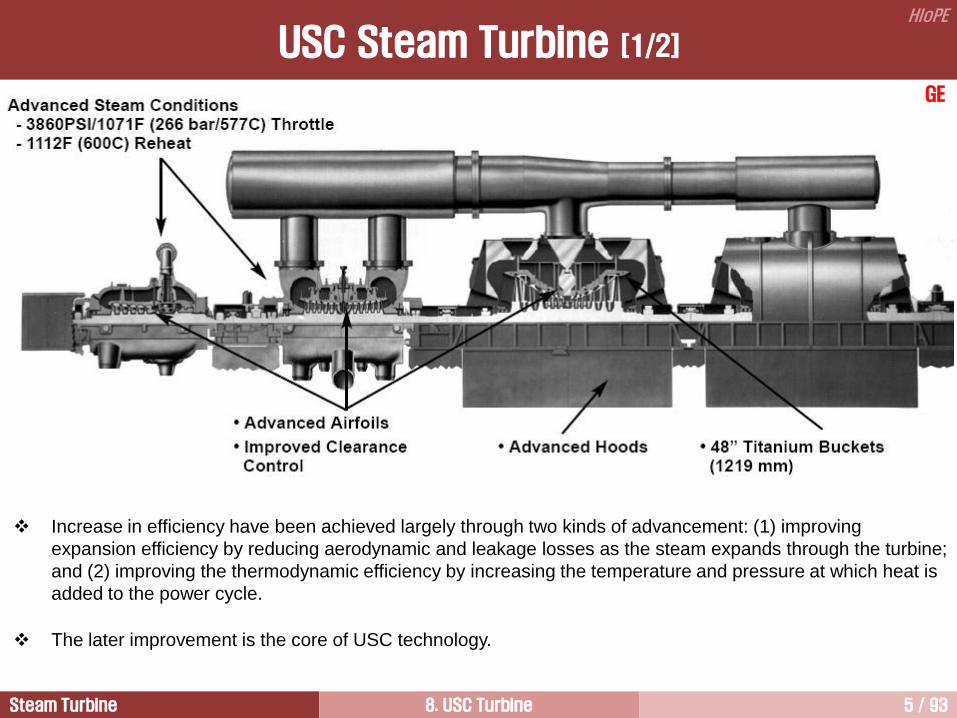
Increase in efficiency have been achieved largely through two kinds of advancement: (1) improving
expansion efficiency by reducing aerodynamic and leakage losses as the steam expands through the turbine;
and (2) improving the thermodynamic efficiency by increasing the temperature and pressure at which heat is
added to the power cycle.
The later improvement is the core of USC technology.

Steam Turbine 8. USC Turbine 6 / 93
HIoPE
USC Steam Turbine [2/2]
GE
The appropriate steam turbine configuration for a given USC application is largely function of the number of
reheats selected, the unit rating, the site back pressure conditions.
Specific design details will also determine the number of flows in a turbine section, the number of stages,
and the LSB length.
In particular, the site ambient conditions
and the condensing system will play a
major role in the selection of the LSB
and the number of LP section flows.
The 1.5 in.Hga would be for a direct
cooled condenser, or cooling tower in a
cold environment.
The 3.5 in.Hga would be for cooling
towers in an area with warmer
environment temperatures.
Steam Turbine 8. USC Turbine 7 / 93
HIoPE
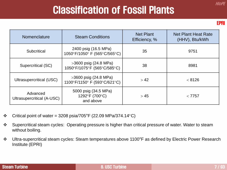
Nomenclature Steam Conditions Net Plant
Efficiency, %
Net Plant Heat Rate
(HHV), Btu/kWh
Subcritical 2400 psig (16.5 MPa)
1050F/1050 F (565C/565C) 35 9751
Supercritical (SC) 3600 psig (24.8 MPa)
1050F/1075F (565C/585C) 38 8981
Ultrasupercritical (USC) 3600 psig (24.8 MPa)
1100F/1150 F (593C/621C) 42 8126
Advanced
Ultrasupercritical (A-USC)
5000 psig (34.5 MPa)
1292F (700C)
and above
45 7757
Classification of Fossil Plants
EPRI
Critical point of water = 3208 psia/705°F (22.09 MPa/374.14C)
Supercritical steam cycles: Operating pressure is higher than critical pressure of water. Water to steam
without boiling.
Ultra-supercritical steam cycles: Steam temperatures above 1100°F as defined by Electric Power Research
Institute (EPRI)

Steam Turbine 8. USC Turbine 8 / 93
HIoPE
Concept of USC
Critical point for water : 3208 psia/705°F (22.09 MPa/374.14C)
The surface tension property of water becomes zero at the critical point.
Therefore, there is no clear distinction between the liquid and the gaseous phase.
p
A
E
D
C
B
K
TO
TS
TK
TE
Wet steam
Water Superheated steam
o x h f g
USC
Subcritical
SC

Steam Turbine 8. USC Turbine 9 / 93
HIoPE
Characteristics of Supercritical
There is no distinction between water and steam in supercritical units

Steam Turbine 8. USC Turbine 10 / 93
HIoPE
P-h Diagram

Steam Turbine 8. USC Turbine 11 / 93
HIoPE
Parameter Units Subcritical USC
Plant size MW 600 600
Net plant efficiency % LHV 38.0 46.0
Total investment cost EU/kW 874 920
Fuel price EU/GJ, bituminous 1.6 1.6
Load factor % 85 85
Cost of electricity c/kWh
UK p/kWh
3.5
2.3
3.3
2.2
Breakdown of cost
of electricity
Fuel
Capital
O&M
c/kWh
1.5
1.3
0.7
1.2
1.4
0.7
Comparison of Cost
Source: Best Practice Brochure (DTI, 2006)

Steam Turbine 8. USC Turbine 12 / 93
HIoPE
History of USC [1/7]

Steam Turbine 8. USC Turbine 13 / 93
HIoPE
Siemens
History of USC [2/7]

Steam Turbine 8. USC Turbine 14 / 93
HIoPE
Te
mp
era
ture
[C
], P
ressu
re [b
ar]
0 1920 1940 1960 1980 2000 2020
700
800
500
600
300
400
100
200
0
10
20
30
40
50
60
1
10
100
1000
10000
Max O
utp
ut Tandem
Com
pound [M
W]
Th
erm
al E
ffic
ien
cy [%
]
Pressure
Thermal Efficiency
Temperature
Power Output
Steam Cycle
Simple Reheat Supercritical
Siemens
History of USC [3/7]

Steam Turbine 8. USC Turbine 15 / 93
HIoPE
Higher maintenance cost .
Lower operational flexibility, availability and reliability.
Control valve wear.
Thermal stress.
Solid particle erosion of turbine blades.
Much more complicated start-up process.
Probability of greater potential for turbine water induction through the main steam system compare to drum-
type subcritical units.
Higher stress corrosion cracking.
More sensitive to feedwater quality.
Experienced Problems in USC Units
History of USC [4/7]
Steam Turbine 8. USC Turbine 16 / 93
HIoPE
History of USC [5/7]
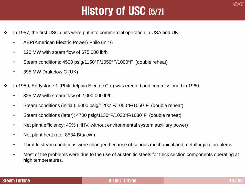
In 1957, the first USC units were put into commercial operation in USA and UK.
• AEP(American Electric Power) Philo unit 6
• 120 MW with steam flow of 675,000 lb/h
• Steam conditions: 4500 psig/1150F/1050F/1000F (double reheat)
• 395 MW Drakelow C (UK)
In 1959, Eddystone 1 (Philadelphia Electric Co.) was erected and commissioned in 1960.
• 325 MW with steam flow of 2,000,000 lb/h
• Steam conditions (initial): 5000 psig/1200F/1050F/1050F (double reheat)
• Steam conditions (later): 4700 psig/1130F/1030F/1030F (double reheat)
• Net plant efficiency: 40% (HHV, without environmental system auxiliary power)
• Net plant heat rate: 8534 Btu/kWh
• Throttle steam conditions were changed because of serious mechanical and metallurgical problems.
• Most of the problems were due to the use of austenitic steels for thick section components operating at
high temperatures.
Steam Turbine 8. USC Turbine 17 / 93
HIoPE
• It is well known that austenitic steels have low thermal conductivity and high thermal expansion resulting
in high thermal stresses and fatigue cracking.
• These problems and initial low availability of many USC power plants temporarily dampened utilities in
building USC power plants and consequently most utilities reverted back to subcritical power plants.
• Additionally, USC plants have another problems compared to subcritical units, such as higher
maintenance costs, lower operational flexibility, lower reliability of steam turbines.
• Many problems were related to the steam turbine control valve wear and tear, to the turbine blade
thermal stress, to the solid particle erosion of blades and valves, and to more complicated start-up
procedures.
• USC units are also more sensitive to feedwater quality. Therefore, full-flow condensate polishing is
required to protect the turbine from stress corrosion cracking.
• After that, through more than 45 years of practices, USC technologies have been unceasingly
developed and gradually perfected.
• Operational experience worldwide has brought the evidence, that present availability of USC power
plants is equal or even higher than those of subcritical ones.
History of USC [6/7]

Steam Turbine 8. USC Turbine 18 / 93
HIoPE
A-USC study (ongoing project by DOE)
• 792 MW, 36.2 MPa/735.5C/760C (5250 psig/1356F/1400F) (single reheat)
• Final feedwater temperature: 332.8C (631F)
• Estimated net plant heat rate: 6293.1 Btu/kWh (6633 kJ/kWh)
• A net plant efficiency of 44.6 to 45.6% is possible with boiler fuel efficiency of 89 to 90% and auxiliary
power between 6.5 to 7.5% of gross generation.
• For 700C plants, it has been reported that double reheat has an efficiency improvement of only 0.7%
(HHV). The double reheat cycle has provided 1.5 to 2.0% of efficiency gain above single reheat at
538C (1000F) throttle conditions.
• The cost/benefit for double reheat will need more evaluation and the first A-USC plant will more likely be
single reheat and employ double reheat when justified later.
History of USC [7/7]
Steam Turbine 8. USC Turbine 19 / 93
HIoPE
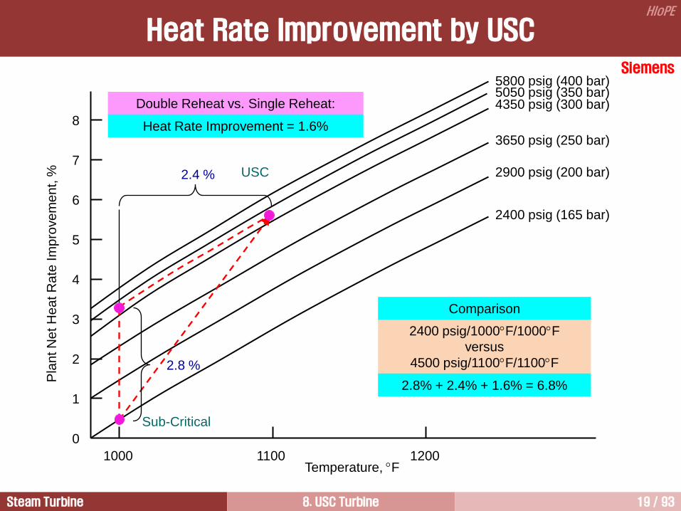
Heat Rate Improvement by USC
1000 1100 1200
Pla
nt N
et H
ea
t R
ate
Im
pro
ve
me
nt,
%
8
7
6
5
4
3
2
1
0
2.8 %
2.4 %
2400 psig/1000F/1000F
versus
4500 psig/1100F/1100F
2400 psig (165 bar)
Sub-Critical
USC 2900 psig (200 bar)
3650 psig (250 bar)
4350 psig (300 bar)
5800 psig (400 bar) 5050 psig (350 bar)
Double Reheat vs. Single Reheat:
Heat Rate Improvement = 1.6%
Temperature, F
Comparison
2.8% + 2.4% + 1.6% = 6.8%
Siemens

Steam Turbine 8. USC Turbine 20 / 93
HIoPE
Efficiency Improvement by USC
7% cycle efficiency improvement by steam condition
from 160bar / 540C / 540C
to 290bar / 600C / 620C
Steam Turbine 8. USC Turbine 21 / 93
HIoPE
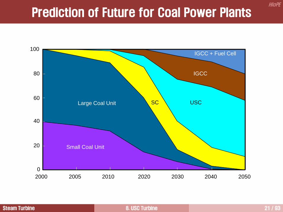
Prediction of Future for Coal Power Plants
20
40
60
80
100
0
2000 2005 2010 2020 2030 2040 2050
Small Coal Unit
Large Coal Unit USC SC
IGCC
IGCC + Fuel Cell

Steam Turbine 8. USC Turbine 22 / 93
HIoPE
EPRI
Current Situation of Coal Plants in US
The construction of new coal fired power plants has reduced greatly in US.
• Coal fired power plant being retired in response to tighter environmental regulations.
While market for new coal power not favorable now, the past few years have shown how volatile the outlook
for power generation can be
• Is it wise to put all eggs in the natural gas basket?
• Gas price is volatile: if all new generation is natural gas fired, electricity prices will fluctuate
correspondingly.
• Gas is a fossil fuel and emits CO2: evenly CCS will be applied to NGCC.
Advanced coal fired USC technology will help stabilize electricity prices and keep them affordable, but if it is
to be available in 2025 needed to work on it today.
Fuel diversity continues to have value in stabilizing cost of electricity.

Steam Turbine 8. USC Turbine 23 / 93
HIoPE
Advantages Considerations
• Increase the plant efficiency significantly
• Reduce fuel consumption for a given output
• Reduce all pollutant and waste, including CO2
• Higher investment cost
• Reliability
• Operational flexibility
USC Technologies
1) Improvement of power density
• Increased number of stages
• Decreased inner ring diameter
• Optimized stage reaction levels
• Optimized stage energy level
2) Improvement of mechanical design
• Advanced vortex blades
• Advanced sealing
• Integral cover bucket (ICB)
• Full arc, hook diaphragm first stage
• Advanced cooling scheme
3) Improved HP/IP/LP shell design
4) Advanced LP design with 45 LSB

Steam Turbine 8. USC Turbine 24 / 93
HIoPE
Advanced USC 4
USC Materials 6
USC Steam Turbine 1
Representative USC Steam Turbine 3
Reduction of CO2 Emission 5
USC Cycle Optimization 2

Steam Turbine 8. USC Turbine 25 / 93
HIoPE
Cycle Optimization
① Reduction of condenser pressure larger heat transfer surfaces, and inclusion of an advanced LP exhaust
hood
② Reduction of boiler flue gas reduction of fan power
③ Reduction of boiler pressure losses and leakages water treatment for water/steam side;
slagging/fouling/erosion reduction for flue gas side
④ Minimization of combustion air excess
⑤ Minimization of thermal losses
⑥ Improvement of boiler and turbine components technical design advanced steam path technologies for
turbine side
⑦ Optimization of main steam parameters advanced steam cycle
⑧ Application of single or double reheat advanced steam cycle
⑨ Optimization of feedwater temperature optimized regenerative cycle

Steam Turbine 8. USC Turbine 26 / 93
HIoPE
Siemens
Efficiency Improvement in PC-Fired Plant
46
45
44
43
42
41
43
42
41
40
39
% %
1.15
1.25
120C
130C
300 bar/600C
250 bar/540C
Single reheat
Double reheat
1.9 in.Hga
0.88 in.Hga
Excess Air Discharge
Flue Gas
Temperature
Main Steam
Condition
Reheat Back
Pressure
Pla
nt N
et E
ffic
ien
cy B
ase
d o
n L
HV
Pla
nt N
et E
ffic
ien
cy B
ase
d o
n H
HV
USC

Steam Turbine 8. USC Turbine 27 / 93
HIoPE
Economic Efficiency Improvement
How to best apply the capital funding available on a power plant project is a critical question for the plant
designer.
The cost basis of technological improvements must be known to make an economic evaluation in today’s
competitive marketplace.
One open literature investigated that the ranking of several technology improvement steps for better plant
efficiency. From least cost to highest cost per efficiency improvement, million US$ / % net LHV efficiency,
these were.
1) Reducing condenser back pressure, 4.6
2) Increasing to 8th extraction point feedwater heater, raising feedwater temperature, 5.7
3) Raising main steam temperature and reheat steam temperature, 12.3
4) Raising main steam temperature, 12.7
5) Using separate BFPT instead of main turbine driven pump, 14.2
6) Raising main steam pressure, 39.1
7) Changing from single to double reheat, 56.7
8) Using separate BFPT condenser, 60.7
Steam Turbine 8. USC Turbine 28 / 93
HIoPE
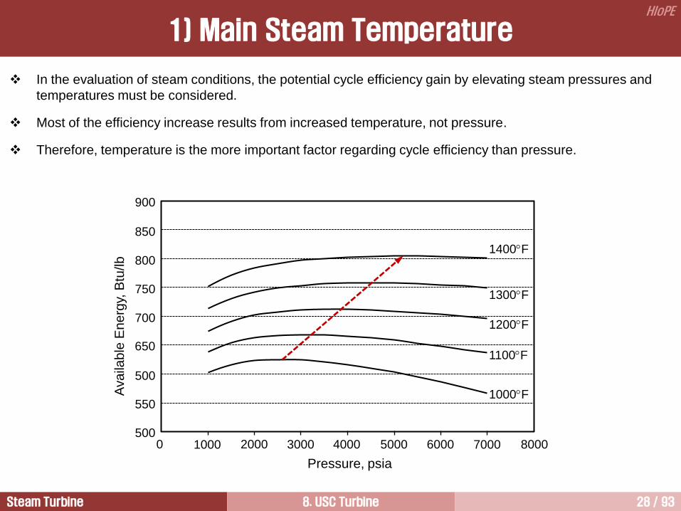
1) Main Steam Temperature
Pressure, psia
Ava
ilab
le E
ne
rgy,
Btu
/lb
0
1000F
1100F
1200F
1300F
1400F
1000 2000 3000 4000 5000 6000 7000 8000
850
900
750
800
650
700
550
500
500
In the evaluation of steam conditions, the potential cycle efficiency gain by elevating steam pressures and
temperatures must be considered.
Most of the efficiency increase results from increased temperature, not pressure.
Therefore, temperature is the more important factor regarding cycle efficiency than pressure.

Steam Turbine 8. USC Turbine 29 / 93
HIoPE
Selection of main steam pressure is of secondary importance in terms of the cycle efficiency.
This is because higher main steam pressure results in higher component costs. Thus, the optimum value
should be found.
The thick pressure parts will require a very limited rate of load change and longer start up times. Therefore,
designers should optimize the operating pressure with the design temperature and select materials having
optimum properties and cost.
Starting with the traditional 2400 psig/1000F single reheat cycle, great improvements in power plant
performance can be achieved by raising inlet steam conditions to levels up to 310 bar (4500 psig) and
temperatures to levels in excess of 600C (1112F).
In a reheat cycle, increasing the main steam pressure will improve the cycle efficiency and this is the
incentive for using supercritical steam conditions.
However, the thermodynamic benefit of increased main steam pressure at a given temperature is subject to
diminishing returns because the significant reduction in volumetric flow at these conditions leads to shorter
and wider turbine blade that is subject to higher passage boundary losses and increased steam path
leakage.
These blade losses act to offset the thermodynamic benefits of elevated steam conditions with increased
main steam pressure.
It is generally accepted that increasing the main steam pressure above 300 bar with steam temperatures of
600C/620C does not offer any further economic benefits.
2) Main Steam Pressure

Steam Turbine 8. USC Turbine 30 / 93
HIoPE
3) Reheat Pressure
Normally, the cold reheater pressure is a quarter of the main steam pressure. Therefore, the selection of the
cold reheat pressure is an integral part of any power plant design. However, it becomes even more important
for plants with USC steam conditions.
The improvement resulting from the use of a HARP can be about 0.5%.
However, economic considerations of the boiler design without a HARP tend to favor a lower reheater
pressure at the expense of a slight decrease in cycle performance. Therefore, the resulting net heat rate gain
is usually larger, approaching 0.6~0.7%.
The use of a HARP results in a lower optimal reheater pressure and a higher optimal feedwater temperature.
Both of these considerations significantly impact the design and cost of the boiler.
As a result, careful optimization need to be done, in considering the use of a HARP, to ensure an
economically optimal cycle selection is made.
For double reheat units without HARP, the best performance would be achieved with the first reheat pressure
of approximately 1450 psi(100 bar).
However, economic considerations associated with the boiler and piping systems would typically favor
reducing this to a lower level.
The typical outcome is that the first reheat pressure is chosen below the thermodynamic optimum while the
second reheat pressure is generally selected slightly above to reduce the LP inlet steam temperature.

Steam Turbine 8. USC Turbine 31 / 93
HIoPE
Double Reheat Cycle with HARP
3) Reheat Pressure

Steam Turbine 8. USC Turbine 32 / 93
HIoPE
Four-Casing, Four-Flow, Double-Reheat Steam Turbine
HP RH1 RH2
3) Reheat Pressure

Steam Turbine 8. USC Turbine 33 / 93
HIoPE
4) LP Inlet Temperature
The use of advanced reheat steam conditions strongly affects the inlet temperature to the LP turbine section.
An increase in hot reheat temperature translates into an almost equal increase in crossover temperature for
a given crossover pressure.
However, the maximum allowable LP inlet temperature is limited by materials associated with the rotor,
crossover, and hood stationary components. Of these, the rotor material temperature limits are usually
reached first.
In addition, the selection of hot reheat temperature (and corresponding effect on LP inlet temperature)
impacts the amount of moisture at the LSB which factors into stress corrosion cracking considerations.
Once the reheat steam conditions are established, then the LP steam conditions can be determined.
If the resulting crossover temperature is too high, the energy ratio between the IP and LP can be changed to
lower this temperature.
Increasing the energy on the IP section will lower the crossover temperature, but it will also impact the cycle
efficiency, increase the number of IP stages, or the loading of the IP stages, increase the height of the final
IP bucket, increase the size of the crossover, or increase the pressure drop through the crossover.
LP inlet temperature can be adjusted by both reheater pressure and crossover pressure.
To lower the crossover temperature, the reheater pressure has to be increased or the crossover pressure
has to be decreased.
Crossover temperature is increased when a HARP is employed because it choose lower reheater pressure
to increase the thermal efficiency of plants.

Steam Turbine 8. USC Turbine 34 / 93
HIoPE
5) Regenerative Rankine Cycle
The Rankine cycle can be used with a feedwater heater to heat the high pressure subcooled water at the
pump exit to the saturation temperature.
The cycle efficiency can be increased, if the feedwater is heated by extracted steam from turbine. In this
case the temperature of the feedwater becomes higher. This cycle is called as a regenerative cycle.
Heating of the feedwater is accomplished by using small amounts of extracted steam having high enthalpy at
various points in the expansion through the turbine.
T
s
condenser
pump1
Boiler
G Turbine
FWH
pump2
Boiler (1)
Feedwater heater (m)
Condenser (1-m)

Steam Turbine 8. USC Turbine 35 / 93
HIoPE
The heat input in the boiler decreases as the final feedwater temperature increases and the heat rejected in
the condenser getting smaller as the feedwater is heated higher using the extracted steam.
The more heaters are used, the higher thermal efficiency.
If a large number of heaters is used, the process of feedwater heating is more reversible.
For this reason, the regenerative cycle improves the thermal efficiency of the power plant.
The feedwater heater arrangement has to be designed to obtain the best heat rate for a given set of USC
steam conditions.
In general, the selection of higher steam conditions will result in additional feedwater heaters and a higher
final feedwater temperature.
The higher final feedwater temperature will have an impact on the boiler cost.
This then requires a system level optimization to determine the best economical solution for the increase in
final feedwater temperature.
In many cases, the selection of a heater above reheat point (HARP) is recommended.
Employment of a HARP has a strong influence on the design of both turbine and boiler.
The use of separate de-superheater ahead of the top heater for unit with a HARP can results in additional
performance gain.
5) Regenerative Rankine Cycle

Steam Turbine 8. USC Turbine 36 / 93
HIoPE
In order to maximize the efficiency with USC steam conditions, a HARP is employed for a optimal higher
feedwater temperature.
Additionally, HARP impact the cost of the boiler significantly.
Cycle No. of Feedwater Heaters HARP Heat Rate Benefit
Single Reheat
(4500 psig, 1100F/ 1100
F)
7
8
8
9
No
No
Yes
Yes
Base Case
+0.2%
+0.6%
+0.7%
Double Reheat
(4500 psig, 1100F/ 1100
F/1100F)
8
9
9
10
No
No
Yes
Yes
Base Case
+0.3%
+0.2%
+0.5%
[ Heat rate impact of alternative feedwater heater configurations ]
5) Regenerative Rankine Cycle

Steam Turbine 8. USC Turbine 37 / 93
HIoPE
SSR: Steam Seal Receiver, SPE: Steam Packing Exhaust
HARP: Heater Above Reheat Point
Single Reheat Cycle with HARP
5) Regenerative Rankine Cycle

Steam Turbine 8. USC Turbine 38 / 93
HIoPE
① Final feedwater temperature = 327C
② First reheat pressure = 9.5 MPa
③ Second reheat pressure = 3.5 MPa
④ Crossover pressure = 1.0 MPa
31.0 MPa / 600 / 610 /610 C
Cycle Optimization - Example
Siemens

Steam Turbine 8. USC Turbine 39 / 93
HIoPE
Advanced USC 4
USC Materials 6
USC Steam Turbine 1
Representative USC Steam Turbine 3
Reduction of CO2 Emission 5
USC Cycle Optimization 2

Steam Turbine 8. USC Turbine 40 / 93
HIoPE
USC Steam Turbine – Siemens [1/5]
Key Technical Features
Model SST5-6000
Gross power output 813 MW
Net plant efficiency (based on
cooling tower) ~45.6% (@ design point)
Main steam conditions 280 bar/600C/610C
LP turbine - LSB 4 Flow - 45
Feedwater preheating 9-stages
Final feedwater temperature 308C
Specific CO2 emission Well below 800 g/kWh
Key Technical Features
Model SST-6000
Gross power output 1200 MW
Main steam conditions 300 bar/600C/620C

Steam Turbine 8. USC Turbine 41 / 93
HIoPE
Mixed steam Cooling
steam Outer
casing
inner
casing
Stage
balance
piston
USC Steam Turbine – Siemens [2/5]

Steam Turbine 8. USC Turbine 42 / 93
HIoPE
The basic design characteristics of HP turbine is the barrel type outer casing design and has an inner casing.
This design can enable 300 bar and 600C.
This rotation-symmetric design has minimum deformation during steady-state and transient operation and a
consequence minimum clearances i.e. minimum leakage losses are achieved.
The barrel type outer casing has an axial split casing which can handle highest pressure loadings by
adopting the wall thickness. This gives an optimal thermal deformation behavior because there is no
horizontal flange. The benefit is small radial clearances between inner casing and blades, that means best
turbine efficiency.
Advanced sealing technologies such as brush seals and abradable coatings reduce steam leakages even
further.
USC steam conditions require the use of thick-walled components.
In order to remove this restriction, an internal bypass cooling system has been developed.
Basically, a small amount of cooling steam passes through radial bores into the small annulus between the
inner and outer HP casing.
The cooling steam is lead through the inner casing towards the balance piston.
Thus, the surface temperature is reduced, creep stresses are reduced, and customers’ lifetime requirements
are met.
The internal bypass cooling also effectively protects the inner surface of the outer casing, which would be
exposed to main steam temperature without the internal bypass cooling.
USC Steam Turbine – Siemens [3/5]

Steam Turbine 8. USC Turbine 43 / 93
HIoPE
As a consequence, it was possible to reduce the wall-thickness of the outer casing and thus enable
faster start-up of the casing.
An improved starting performance is the main customer benefit of this innovative concept.
3DV technology (3-dimensional design with variable reaction levels) is applied for HP and IP blades.
The IP turbine is designed to take reheat steam
temperature of 620C. Thus, the first stage blades are
made of nickel alloy.
The high steam temperature can be handled by
reducing the rotor surface temperature by a cooling
principle named vortex cooling.
This cooling principle enables a temperature decrease
due to the reduction of relative steam velocity at the
rotor surface.
The double flow, double casing turbine has a full arc
admission. This first stage has zero flow losses and
gives the best transition from a radial flow in the inlet
ring to an axial flow in the double flow blade path.
USC Steam Turbine – Siemens [4/5]

Steam Turbine 8. USC Turbine 44 / 93
HIoPE
The LP turbine consists of a double flow with a horizontal split casing.
The push rod permits parallel axial thermal expansion of LP rotor and inner casing by directly coupling the IP
outer casing with the LP inner casing.
This reduces clearances between rotor and casing and improves the efficiency.
Free-standing 45 LSBs made by steel provide an annular area of 12.5 m2 per flow. Titanium LSB will be
applied in the near future.
Frequency control through condensate throttling.
USC Steam Turbine – Siemens [5/5]

Steam Turbine 8. USC Turbine 45 / 93
HIoPE
USC Steam Turbine – GE [1/5]
Key Technical Features
Gross power output 1050 MW
Net plant efficiency 48.7% (@ design point)
Main steam conditions 250 bar/600C/610C
(3626 psia/1112F/1130F)
LP turbine - LSB 4 Flow - 48
Arrangement of rotor shaft Cross-compound
Key Technical Features
Gross power output 1000 MW
Net plant efficiency ?
Main steam conditions 260 bar/610C/621C
(3770 psia/1150F/1180F)
LP turbine - LSB 4 Flow - 45
Arrangement of rotor shaft Tandem-compound
Steam Turbine 8. USC Turbine 46 / 93
HIoPE
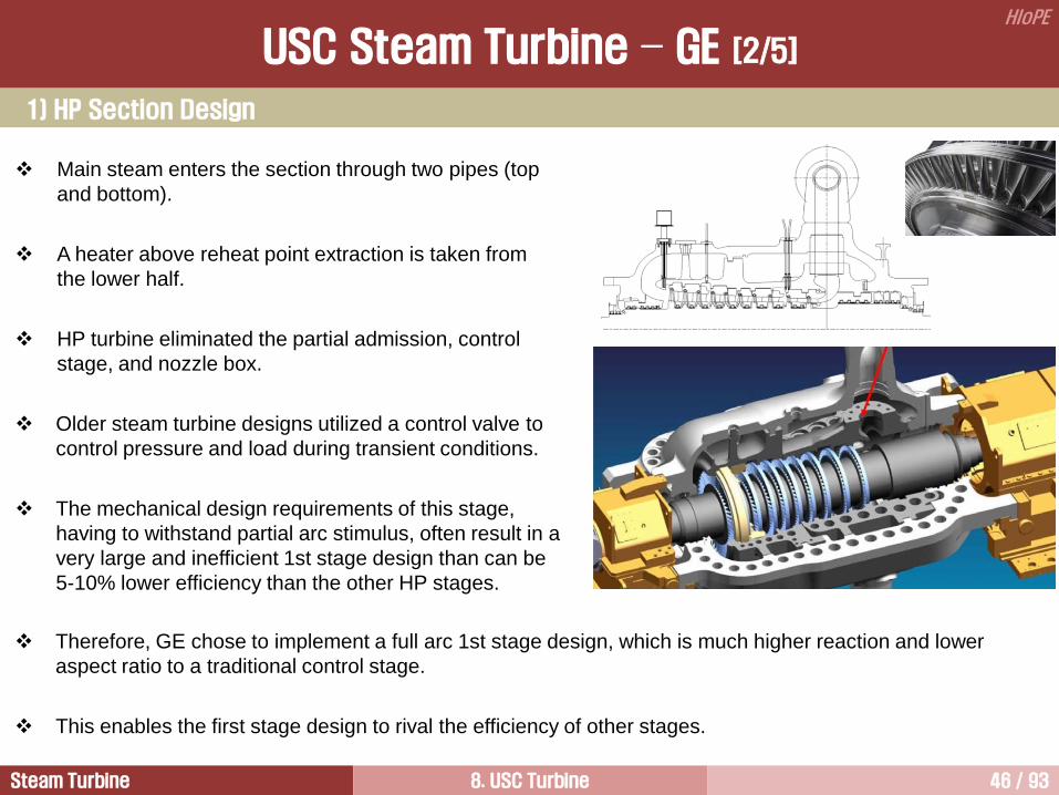
Main steam enters the section through two pipes (top
and bottom).
A heater above reheat point extraction is taken from
the lower half.
HP turbine eliminated the partial admission, control
stage, and nozzle box.
Older steam turbine designs utilized a control valve to
control pressure and load during transient conditions.
The mechanical design requirements of this stage,
having to withstand partial arc stimulus, often result in a
very large and inefficient 1st stage design than can be
5-10% lower efficiency than the other HP stages.
1) HP Section Design
Therefore, GE chose to implement a full arc 1st stage design, which is much higher reaction and lower
aspect ratio to a traditional control stage.
This enables the first stage design to rival the efficiency of other stages.
USC Steam Turbine – GE [2/5]

Steam Turbine 8. USC Turbine 47 / 93
HIoPE
To allow this, however, changes need to be made to allow the turbine quickly and efficiently respond to load
swings.
Therefore, GE will utilize an overload valve that will bypass the first stage and allow additional flow/load
response.
An overload admission was added for frequency control and capacity margin.
Elimination of the nozzle box required that two inner shells be used.
In this arrangement, the inlet #1 inner casing is subject to adjacent stage steam conditions on its inner
surfaces and a downstream stage’s steam pressure on its outer surface.
The buckets of the first four stages are made of nickel-based material due to the high temperature creep
requirements. The remaining buckets are conventional 12Cr material.
All 10 stages will utilize integral cover buckets with advanced tip seals.
The wheel spaces of the first two stages are cooled using external cooling steam.
A combination of brush, variable clearance, and conventional shaft seals are used in the HP section.
The corresponding outer casing inner surface is subjected to steam conditions at the same downstream
steam pressure.
Full admission design alleviated the mechanical challenges associated with partial admission design and the
control stage.
1) HP Section Design – 1st Stage
USC Steam Turbine – GE [3/5]

Steam Turbine 8. USC Turbine 48 / 93
HIoPE
2) IP Section Design
The IP section is designed in a double flow configuration.
Two feedwater heater extractions are taken from the lower half.
Single casing construction is used.
The number of stages is 8.
The buckets of the first three stages are made of nickel-based material due to the high temperature creep
requirements. The remaining buckets are conventional 12Cr material.
All 8 stages will utilize integral cover buckets with advanced tip seals.
The wheel spaces of the first two stages are cooled using cooling steam, from HP section.
A combination of variable clearance and conventional shaft seals are used in the HP section.
USC Steam Turbine – GE [4/5]
Steam Turbine 8. USC Turbine 49 / 93
HIoPE
3) LP Turbine Design
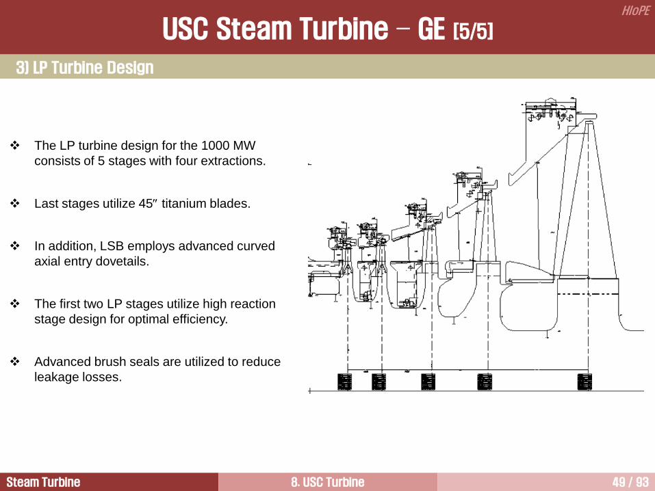
The LP turbine design for the 1000 MW
consists of 5 stages with four extractions.
Last stages utilize 45 titanium blades.
In addition, LSB employs advanced curved
axial entry dovetails.
The first two LP stages utilize high reaction
stage design for optimal efficiency.
Advanced brush seals are utilized to reduce
leakage losses.
USC Steam Turbine – GE [5/5]

Steam Turbine 8. USC Turbine 50 / 93
HIoPE
700C Steam Turbine Development [ALSTOM]
Welding Balance Piston
USC Steam Turbine – Alstom

Steam Turbine 8. USC Turbine 51 / 93
HIoPE
USC Steam Turbine - Doosan
Key Technical Features
Output @ Max Guarantee Rating 1000 MW
Output @ VWO 1100 MW
Net plant efficiency 49% (estimated value)
Main steam conditions 260 bar/610C/621C
LSB 4 Flow - 45
Cycle Single reheat regenerative
Bearings
LP Casing
LP Inner Casing
Reheat Stop and
Intercept Valves Double Shells Packing
Head
Packing
Head
Wheels and
Diaphragms

Steam Turbine 8. USC Turbine 52 / 93
HIoPE
Advanced USC 4
USC Materials 6
USC Steam Turbine 1
Representative USC Steam Turbine 3
Reduction of CO2 Emission 5
USC Cycle Optimization 2
Steam Turbine 8. USC Turbine 53 / 93
HIoPE
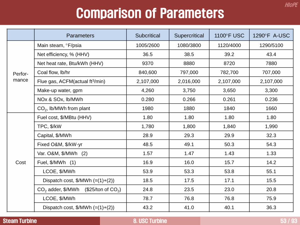
Parameters Subcritical Supercritical 1100F USC 1290F A-USC
Perfor-
mance
Main steam, F/psia 1005/2600 1080/3800 1120/4000 1290/5100
Net efficiency, % (HHV) 36.5 38.5 39.2 43.4
Net heat rate, Btu/kWh (HHV) 9370 8880 8720 7880
Coal flow, lb/hr 840,600 797,000 782,700 707,000
Flue gas, ACFM(actual ft3/min) 2,107,000 2,016,000 2,107,000 2,107,000
Make-up water, gpm 4,260 3,750 3,650 3,300
NOx & SOx, lb/MWh 0.280 0.266 0.261 0.236
CO2, lb/MWh from plant 1980 1880 1840 1660
Cost
Fuel cost, $/MBtu (HHV) 1.80 1.80 1.80 1.80
TPC, $/kW 1,780 1,800 1,840 1,990
Capital, $/MWh 28.9 29.3 29.9 32.3
Fixed O&M, $/kW-yr 48.5 49.1 50.3 54.3
Var. O&M, $/MWh (2) 1.57 1.47 1.43 1.33
Fuel, $/MWh (1) 16.9 16.0 15.7 14.2
LCOE, $/MWh 53.9 53.3 53.8 55.1
Dispatch cost, $/MWh (=(1)+(2)) 18.5 17.5 17.1 15.5
CO2 adder, $/MWh ($25/ton of CO2) 24.8 23.5 23.0 20.8
LCOE, $/MWh 78.7 76.8 76.8 75.9
Dispatch cost, $/MWh (=(1)+(2)) 43.2 41.0 40.1 36.3
Comparison of Parameters

Steam Turbine 8. USC Turbine 54 / 93
HIoPE
A-USC Steam Conditions
Steam Conditions Remark
EPRI 5100 psia/1290F/1330F (347 bar/700C/721C)
Net plant efficiency = 43.4% (HHV)
• Boiler efficiency = 87.2%
• HP/IP/LP effi. = 90/94.2/88.6%
US. DOE 5015 psia/1350F/1400F (341 bar/732C/760C) Materials program objective
EU 5500 psia/1290F/1330F (375 bar/700C/721C) Net plant efficiency = 52-55% (LHV)
Some abbreviations and its definition
TPC: Total Plant Cost.
LCOE: Levelized Cost of Electricity.
Fixed O&M: personnel and insurance costs.
Variable O&M: cost depending upon the operation regime of the plant. Included items are:
• Inspection and overhauls, including labor, parts, and rentals
• Water treatment expenses
• Catalyst replacement
• Major overhaul expences
• Air filter replacements

Steam Turbine 8. USC Turbine 55 / 93
HIoPE
A-USC (Advanced Ultra Supercritical) means a coal fired power plant design with the inlet steam
temperature of 700C to 760C (1292F to 1400F).
The higher the inlet steam temperature, the higher the efficiency of a plant.
The higher the efficiency of a plant, the less fuel consumption, and fewer emission are produced during
electricity generation.
Therefore, the purposes of A-USC plants are reducing the emission of CO2 and its capture cost, and fuel
consumption by increasing the efficiency of power plants.
When the heat is supplied at 760C, the Carnot cycle efficiency is 69.9%, while the expected A-USC net
plant efficiency is 52.7% (6825 kJ/kWh, or 6475 Btu/kWh).
USC uses ferritic and stainless steels, while A-USC requires nickel alloy materials.
The costs of the higher priced nickel alloys must be balanced with the savings in less fuel consumption,
lower weight and size of equipment, and cost avoidance for emission allowance requirements.
TPC(Total Plant Cost) for 1290F A-USC is 11% higher than for SC unit, but potential to halve the difference
because the cost of high temperature materials is getting lower.
A-USC plants have the potential for lower cost of electricity especially when combined with the requirements
to capture carbon for sequestration (CCS).
The plant production costs per megawatt-hour are the lowest for A-USC w/CCS based on plant economic
studies for coal firing. Combining CCS with A-USC plants will provide lower cost of electricity generation with
90% CO2 capture.
Currently, A-USC studies have been focused on 50Hz machines. This is because the rotating components of
60Hz machines require reduced steam temperatures by 40F to meet strength requirements.
Generals

Steam Turbine 8. USC Turbine 56 / 93
HIoPE
Selection of Throttle Pressure
Throttle pressure for the Rankine cycle is fundamental to the optimum amount of available energy of the
working fluid at the specified operating throttle temperature. The optimum throttle pressure increases with
throttle temperature.
Throttle pressure for the desired throttle temperature of 700 to 760C will most feasible in the range of 5000
to 5500 psi.
Considering a single reheat cycle, the optimum available energy peaks at about 2500 psia for 1000F, about
4000 psia for 1200F, and at about 5000 psia for 1400F.
Because higher pressure results in higher component costs, the optimum available energy should be
investigated.
Higher steam pressure can help to reduce the flow path pipe size delivering the energy flow.
The more compact plant equipment will help with cost savings as long as pressure vessel thickness and
material costs are at the optimum.
Due to concerns that very thick parts will require a very limited rate of load change and longer start up times,
the throttle pressure should be determined with optimum properties and cost.
Temperature is the more important factor regarding cycle efficiency.
Selection of pressure is of secondary importance in terms of efficiency.
Setting the HP throttle pressure, the IP inlet pressure and the LP exhaust pressure is important for the
optimization and meeting acceptable operating conditions.
Steam Turbine 8. USC Turbine 57 / 93
HIoPE
Double Reheat Cycle
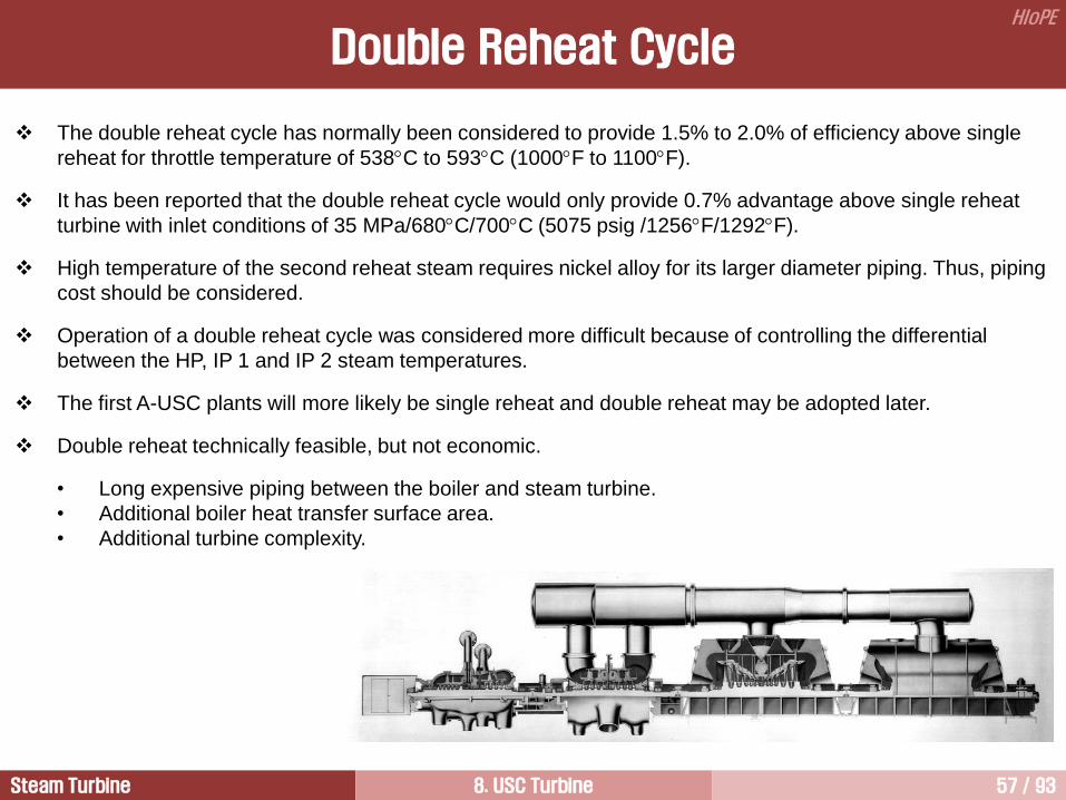
The double reheat cycle has normally been considered to provide 1.5% to 2.0% of efficiency above single
reheat for throttle temperature of 538C to 593C (1000F to 1100F).
It has been reported that the double reheat cycle would only provide 0.7% advantage above single reheat
turbine with inlet conditions of 35 MPa/680C/700C (5075 psig /1256F/1292F).
High temperature of the second reheat steam requires nickel alloy for its larger diameter piping. Thus, piping
cost should be considered.
Operation of a double reheat cycle was considered more difficult because of controlling the differential
between the HP, IP 1 and IP 2 steam temperatures.
The first A-USC plants will more likely be single reheat and double reheat may be adopted later.
Double reheat technically feasible, but not economic.
• Long expensive piping between the boiler and steam turbine.
• Additional boiler heat transfer surface area.
• Additional turbine complexity.

Steam Turbine 8. USC Turbine 58 / 93
HIoPE
Turbine Cycle
The capacity of the steam turbine under studying is 750 MW.
The steam turbine throttle conditions are 35 MPa/732C/760C (5000 psig /1350F/1400F) with 2 in.Hga
condenser pressure.
An additional new requirement of an A-USC boiler is to deliver cooling steam from a source such as the
primary superheater at 1.5% of main steam flow rate to the HP outer casing.
1.5% cold reheat steam is retained at the turbine for IP turbine outer casing cooling.
Feedwater temperature to the economizer has ranged from 630F to 649F at MCR. Reducing the
economizer gas outlet temperature is a little more difficult because of the higher final feedwater temperature
of A-USC.
A-USC steam turbine section efficiencies are expected to lie in the following range depending on offered by
various vendors; HP: 89.2~93.3%, IP: 90.5~96.6%, LP: 90.6~95.8%.
The net plant efficiency is in the range 46~48% based on HHV.
CCS will affect net plant efficiency because total auxiliary power for CCS will be about 20.5% of gross power
generation.
Oxy-combustion A-USC plant efficiency with Ohio coal is estimated to be 38.1% (HHV) with 90% capture of
carbon dioxide.

Steam Turbine 8. USC Turbine 59 / 93
HIoPE
Steam Turbine
Major characteristics
• HP turbine may have two stage because of limited use of nickel alloy
• Start up time longer because of higher temperature, but frequency control not expected to be affected
• BFW extractions are similar, but final feedwater temperature will become higher
Same availability
• A-USC steam turbines should have same availability as conventional turbines.

Steam Turbine 8. USC Turbine 60 / 93
HIoPE
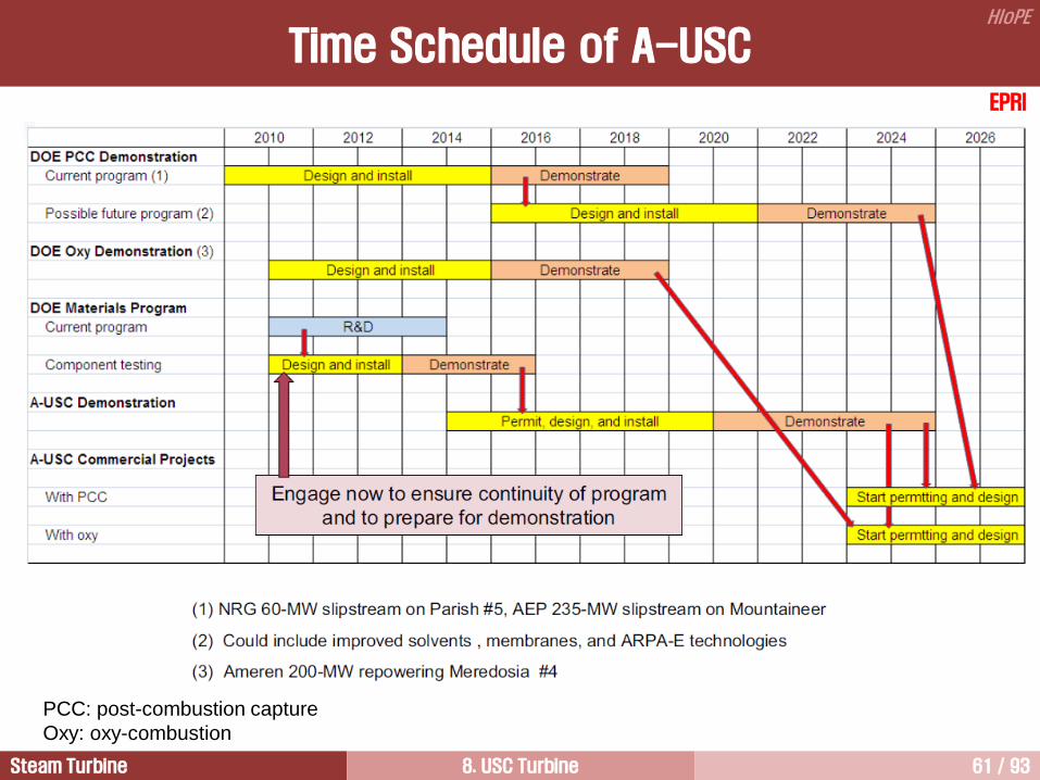
Time Schedule of A-USC
EPRI
Steam Turbine 8. USC Turbine 61 / 93
HIoPE
EPRI
PCC: post-combustion capture
Oxy: oxy-combustion
Time Schedule of A-USC

Steam Turbine 8. USC Turbine 62 / 93
HIoPE
AD 700 Cycle
AD 700 is an advanced 700C PF power plant has being developed in European Union.
Steam conditions: 375 bar/700C/ 720C
Plant efficiency: 52-55%
Fuel saving and CO2 emission reduction of up to 15% compared with the best available technology of today.
Construction and commissioning will be finished in 2013.

Steam Turbine 8. USC Turbine 63 / 93
HIoPE
Time Schedule of AD 700 Cycle

Steam Turbine 8. USC Turbine 64 / 93
HIoPE
Advanced USC 4
USC Materials 6
USC Steam Turbine 1
Representative USC Steam Turbine 3
Reduction of CO2 Emission 5
USC Cycle Optimization 2

Steam Turbine 8. USC Turbine 65 / 93
HIoPE
Clean and cheap power generation is of prime importance to cope with the challenges imposed by an
increasing energy demand throughout the world.
In recent years, costs associated with CO2 emissions have attracted more attention because of global
warming.
Carbon capture and storage (CCS) and capture ready power plant designs are becoming increasingly
important for the evaluation of investments into new power plants and in addition retrofit solutions for the
existing power plants are required.
Efficiency improvement is a means for reducing emission of CO2, the costs of carbon capture, water use,
particulates, sulfur dioxides (SO2) and nitrogen oxides (NOx) emissions, and fuel consumption.
As coal is more abundant in many parts of the world, coal price is more stable than natural gas price.
However, greater CO2 emissions increase the need for more efficient coal-fired power plants.
USC steam power plants meet notably the requirements for high efficiency to reduce both fuel costs and
emissions as well as for a reliable supply of electric energy at low cost.
Recent developments in steam turbine technologies and high-temperature materials allowed for significant
efficiency gains.
Due to CO2 emission limits and corresponding penalties, the conventional coal-fired power plant with the
efficiency lower than 40% become less cost-effective.
NETL and EPRI studies show that current CCS technologies have CO2 removal costs of $50 to 70/ton.
Background for USC Power Plants

Steam Turbine 8. USC Turbine 66 / 93
HIoPE
CO2 Emission vs. Plant Efficiency
CO
2 E
mis
sio
n, g
/kW
h
800
600
1200
200
0
400
Net Plant Efficiency, % (LHV)
36 48 28 32 40 44 52 56
1000

Steam Turbine 8. USC Turbine 67 / 93
HIoPE
CO2 Emission vs. Net Plant Efficiency
Net Plant Efficiency, %
CO
2 E
mis
sio
ns, to
n/M
Wh
0.90
37
CO
2 R
ed
uction
, %
38 39 40 41 42 43 44 45 46 47 48 49 50
0.85
0.80
0.75
0.70
0.65
0.60
CO2 emissions, ton/MWh Percent CO2 reduction from
subcritical PC plant
Ultrasupercritical
PC plant range
Subcritical
PC plant
0
5
10
15
20
25
30

Steam Turbine 8. USC Turbine 68 / 93
HIoPE
CO2 Emission vs. Plant Efficiency
The need of further reduction of environmental emissions from coal combustion is driving growing interest in
high-efficiency and low-emissions coal fired power plants.
Every 28C (50F) increase in throttle and reheat temperature results in approximately 1.5% improvement in
heat rate.
Every 1% improvement in plant efficiency results in approximately 2.5% reduction in CO2 emission.
An increase in plant efficiency from 30% to 50% reduce CO2 emissions about 40%.
A-USC plants having net plant efficiency of 45%, without CCS(Carbon Capture and Sequestration), will
produce about 22% less CO2 than the average subcritical plants that include the majority of units currently in
service and operating at about 35% net plant efficiency.
Combining CCs with A-USC plants will provide lower cost of electricity generation with 90% carbon capture.
A-USC will lower the CO2 per kWh, thus reducing the size of the CCS equipment.
Oxy-combustion CCS plant that achieve 90% carbon capture use about 20.5% auxiliary power which
includes the compression purification unit (CPU), additional cooling tower, air separation unit (ASU), and
polishing scrubber.
The efficiency penalty associated with CO2 capture based on Siemens advanced process is 9.2%.

Steam Turbine 8. USC Turbine 69 / 93
HIoPE
1100 USC
Net P
lan
t E
ffic
ien
cy,
% (
HH
V)
25
35
40
45
30
1100 USC
w/PCC
1300 USC
w/PCC
1300 USC
w/PCC (1)
1300 USC
w/PCC (2)
1400 USC
w/PCC (3)
(1) Back-end heat recovery (2) Double reheat
(3) 1350F with back-end heat recovery and double reheat
Efficiency Gain with CCS Incorporated
1100F class USC loses efficiency of 7.7% when CCS is incorporated.
By going to A-USC conditions of 1300-1400F, plus select other improvements, this loss can be more than
recovered.
Net efficiency improvements will be enhanced by CCS improvements.
EPRI

Steam Turbine 8. USC Turbine 70 / 93
HIoPE
Lignite: 980~1,230
Hard coal: 790~1,080
Oil: 890
NG: 640
NG Comb. cycle
Unit: g CO2/kWh
410~430
Solar 80~160
Nuclear: 16~23
Wind: 8~16
Hydro power: 4~13
Electricity generation with CCS
CO2 Emissions from Different Power Plants
The efficiency penalty associated with CO2 capture:
• Rankine cycle: 9.2% (based on Siemens advanced process)
• Combined cycle: 8% (based on GE 9FB.03 unit with a 3-pressure HRSG)

Steam Turbine 8. USC Turbine 71 / 93
HIoPE
There are three major technologies for CCS for industrial and power plants applications.
• Post-combustion separates CO2 from the flue gases produced by combustion of a fuel in air.
• Oxy-fuel combustion uses oxygen instead of air for combustion, producing a flue gases that contains
mainly H2O and CO2. Therefore, CO2 is easily separated by condensing the water vapor.
• Pre-combustion technology processes the primary fuel in a reactor to produce separate stream of CO2 for
storage and H2, which is used as a fuel.
CO2 Capture Technologies
Post-combustion capture
• chemical absorption process
• gas-fired power plant in Malaysia
• constructed by MHI
Pre-combustion capture • physical solvent process
• coal gasification plant in US

Steam Turbine 8. USC Turbine 72 / 93
HIoPE
CO2
Separation Power & Heat
Gasification Reformer +CO2 Sep. Power & Heat
Power & Heat
Air Separation
Process + CO2 Sep.
Post-
combustion
Pre-
combustion
Oxy-
combustion
Industrial
processes
Coal
Gas
Biomass
Coal
Biomass
Coal
Gas
Biomass
Coal
Gas
Biomass
Air
Air/O2
Steam CO2
N2,O2
N2, O2
CO2
CO2
N2 O2
Gas, Oil
Air/O2
Air
Air
Raw material Gas, Ammonia, Steel
H2
CO2
CO2 Compression
& Dehydration
CO2 Capture Process and Systems

Steam Turbine 8. USC Turbine 73 / 93
HIoPE
De
NO
x
FG
D
EP
CO
2
Cap
ture
Flu
e G
as
Coo
ling
Chim
ne
y
Continuous
Emission
Monitoring
System
Remove
85-90% of
NOx
Remove
99.7% of
Fly Ash
Remove
90-95% of
SO2
Remove
90% of
CO2
Post-Combustion Capture Technology [1/3]

Steam Turbine 8. USC Turbine 74 / 93
HIoPE
Post-Combustion Capture Technology [2/3]

Steam Turbine 8. USC Turbine 75 / 93
HIoPE
The most common method for separating CO2 from a gas stream in use today is the chemical absorption
using alkaline solvents.
The flue gas passes through an aqueous alkaline solvent, and since CO2 is acidic it is bound to the solvent.
The absorption process takes place in the absorption column.
The flue gas enters at the bottom of the absorber, while the solvent is pumped to the top of the absorber.
After the reaction and CO2 absorption, the rich- CO2 solvent drops to the bottom of the absorber and then it is
pumped to the separation unit (CO2 stripper).
In CO2 stripper the rich-CO2 solvent is heated up depending on the solvent type to 100-140C.
This reverses the absorption process and releases most of the CO2 in a pure stream for compression and
transport. The lean- CO2 solvent is transported back to the absorber for reuse.
A variety of solvents could be used in the absorption/regeneration process and each has its advantages and
disadvantages.
Choosing the right solvent is important to reduce the energy penalty of the capture process.
The most used solvent for CO2 capture is monoethanolamine.
Aqueous ammonia is used as well in capturing CO2 from flue gases.
Post-Combustion Capture Technology [3/3]

Steam Turbine 8. USC Turbine 76 / 93
HIoPE
Oxy-Fuel Combustion Capture Technology [1/2]
Steam Turbine 8. USC Turbine 77 / 93
HIoPE
In oxy-fuel combustion capture technology nearly pure oxygen is used for combustion instead of air.
Therefore, combustion products are mainly CO2 and H2O.
If fuel is burnt in pure oxygen, the flame temperature is exceedingly high. Therefore, CO2 and /or H2O-rich
flue gas is recirculated to the combustor to moderate the temperature.
The steam can easily be removed by condensation, leaving a rich- CO2 stream ready for compression and
storage.
Oxygen is usually produced in cryogenic air separation unit which is the major demanding component in the
process.
Oxy-Fuel Combustion Capture Technology [2/2]

Steam Turbine 8. USC Turbine 78 / 93
HIoPE
Pre-Combustion Capture Technology
The pre-combustion technology refers to removing of the carbon from the fuel before combustion.
Pre-combustion capture involves reacting fuel with oxygen or air and/or steam to give mainly syngas
composed of carbon monoxide and hydrogen.
The hydrogen can then be used directly as a fuel in the gas turbine.
Burning hydrogen emits no CO2 and primary
exhaust gas from hydrogen combustion is
water.
Both pre- and post-combustion technologies
are available at a significant drop in
performance.

Steam Turbine 8. USC Turbine 79 / 93
HIoPE
Carbon Capture Ready Power Plants [1/4]
A power plant in the capture ready design will be able to integrate the CO2 capture unit when the necessary
regulatory or economic drivers are in place.
In the EU, a capture ready assessment is mandatory for all new fossil power plants 300 MW, in other
regions capture ready programs are already implemented or still under discussion.
The aim of building power plants that are capture ready is to reduce the risk of space and connections.
In the capture ready assessment the following topics have to be addressed.
• Evaluation of available CO2 transportation and accessible CO2 storage options.
• Reservation of sufficient area on the site for the later retrofit of the CO2 capture unit including CO2
compression and all plant integration measures.
• Assessment of the economic and technical aspects for the later retrofit and integration of the CO2
capture unit.
The capture process consumes LP steam for solvent regeneration and electrical energy for the solvent
pumps and the CO2 compressors.
Cooling water is needed as well.
The mass and energy flow rates at the interfaces depend on the capture process.
Optimizing the heat integration between the power plant and the CO2 capture unit including CO2
compression will be a decisive factor for the competitiveness of a steam power plant with CO2 capture.
Siemens

Steam Turbine 8. USC Turbine 80 / 93
HIoPE
Four Main Topics should be Considered
1) Water supply and cooling tower
• These systems need to be adapted.
• Later capacity extensions should be considered in civil and in the plant layout from the beginning.
2) Auxiliary power consumption
• The electrical auxiliary load will be doubled after retrofit of the capture unit, mainly caused by the CO2
compression.
• Sufficient space, additional auxiliary transformers, switchyard and cable routes need to be considered.
3) Steam extraction
• A significant amount of the available LP steam (approx. 40%) needs to be extracted from the steam
turbine and has to be supplied to the capture unit for solvent regeneration. (2.7 GJ/ton CO2 captured,
approximately 40% of LP steam)
• Avoiding thermodynamic inefficiencies associated with throttling at full and partial load as well as keeping
the capital costs low are the main challenges.
• In addition, the different solvents and capture processes under competition vary in demand and properties
of LP steam.
4) Flue gas path
• Additional space need to be reserved for the connection of the flue gas duct with the capture unit (T-
Branch), for the installation of the additional flue gas fan and for the adaption of the FGD unit.
Carbon Capture Ready Power Plants [2/4]

Steam Turbine 8. USC Turbine 81 / 93
HIoPE
Capture Ready Requirements [Siemens]
Steam turbine building sufficient space/foundation for
• Modification of turbines
• Steam and condensate pipes
• Installation of heat exchangers
Steam turbines • Extraction of approximately 40% of
LP crossover steam
• Options for modification of turbines
expand on operation modes (part
load, full load capability without
CO2 capture other plant and site
conditions)
Electrical auxiliary load sufficient space for
• Additional auxiliary transformer(s)
• Switchyard
• Cable routes
Cooling system sufficient space for
• Additional circulation pumps
• Service water system
• Sufficient cooling capacity of
cooling tower
Condensate system sufficient space for
• Heat exchangers for low grade
heat utilization
• Additional piping routes with
supporting structure/racks
Raw water & cooling water
supply / Waste water
treatment • Sufficient space for enlargement
• Secure water utilization rights
FGD • Either consider capacity
extension in column
design
• or provide space for
enlarged FGD unit
Air heating Optional: space for
installation of heat
exchanger(s) for lowest
grade heat utilization
Exhaust ducts • Consider p from CO2
absorption unit
• Later flue gas connection
to capture unit (T-branch)
Flue gas fan • Upgradable design
• or additional space for
installation of second
fan downstream of FGD
Carbon Capture Ready Power Plants [3/4]

Steam Turbine 8. USC Turbine 82 / 93
HIoPE
Challenges
The biggest challenge is the design of LSB.
Approximately 40% of LP steam has to be extracted from the cross-over pipe.
The varying flow will change the last stage loading and may turn the stage into turn-up mode.
In this case, windage heat is generated near the hub region because rotating LSBs feed energy into the
trapped steam. Thus, water spray nozzles are installed at the exhaust section to cool the high temperature
steam.
Typically, large coal-fired power plants have two- or three LP turbines. Therefore, one could be removed from
operation when the plant is operated in capture mode.
However, plants have one LP turbine may have lower performance when the plant is operated in capture
mode because of turn-up loss. Therefore, a true capture ready plant is not feasible in this case, and the plant
has to be modified when changed for capture operation.
Carbon Capture Ready Power Plants [4/4]

Steam Turbine 8. USC Turbine 83 / 93
HIoPE
Advanced USC 4
USC Materials 6
USC Steam Turbine 1
Representative USC Steam Turbine 3
Reduction of CO2 Emission 5
USC Cycle Optimization 2

Steam Turbine 8. USC Turbine 84 / 93
HIoPE
Substantial reduction in emissions from coal-fired power plants can be achieved only by employing most
advanced and highly efficient modern power generation technologies.
The most direct and economical method for this is the evolutionary advance of increasing steam
temperatures and pressures at the steam turbine inlet well beyond the critical point of water.
To allow this increases, advanced materials are needed that are able to withstand the higher temperatures
and pressures in terms of strength, creep, and oxidation resistance.
USC power plants have faced particular challenges for maintaining equipment reliability and flexible
operation at more advanced throttle steam conditions.
One of most important aspects is the role of pressure on steam-side oxidation.
Most of the efficiency increase results from increased temperature, not pressure.
As a consequence, material requirements, in terms of high temperature strength and steam side oxidation,
could lead to the use of lower pressures (than the goal of 38.5 MPa) to make USC turbine economical, and
yet still beneficial in terms of efficiency increases.
Since ferritic steels are capable of meeting the strength requirements up to of approximately 620C, there is
no obstacle for USC technology within this temperature range.
As the steam condition moved to A-USC, ferritic and stainless steels will be replaced by nickel based alloys
because those have higher material strength and corrosion resistance.
Advanced material application, especially of titanium for LSB with lower density allows longer blades to be
used and thus the exhaust annulus area to be increased.
Generals

Steam Turbine 8. USC Turbine 85 / 93
HIoPE
Importance of Fireside Corrosion

Steam Turbine 8. USC Turbine 86 / 93
HIoPE
Alloy Strength
H282
IN740
H230
TP310HCbN
IN617
S304H
T24
T92
TP347H
T22
T12
1100 1200 1300 1400 1500 1600 700 800 900 1000
Temperature, F
Allo
wa
ble
Str
ess, ksi
50
45
40
35
30
25
20
15
10
5
0
Ferritic Nickel Alloys
Au
ste
nit
ic

Steam Turbine 8. USC Turbine 87 / 93
HIoPE
Temperature Capability of Materials
Alstom

Steam Turbine 8. USC Turbine 88 / 93
HIoPE
600 650 700 750 500 550
Temperature, C
10
0,0
00
h C
ree
p R
up
ture
Str
ess, M
Pa
275
250
225
200
175
25
HCM25 7CrMoTiB1010 HCM12
P92 Super 304 Nf709 174
617 Pipe 617 Tube Alloy 263/740
150
125
100
75
50
Creep Rupture Stress
Candidates of AD 700 Materials
Thermal expansion coefficients, hardness, toughness and other mechanical properties are important to the
design and fabrication of materials. In addition, welds and weldments for both thick sections and tubes should
be tested. To achieve 1400F (760C) steam temperatures, longer creep rupture strength test at higher
temperatures is very important to the A-USC design.

Steam Turbine 8. USC Turbine 89 / 93
HIoPE
Net Efficiency and Materials
Steam Turbine 8. USC Turbine 90 / 93
HIoPE
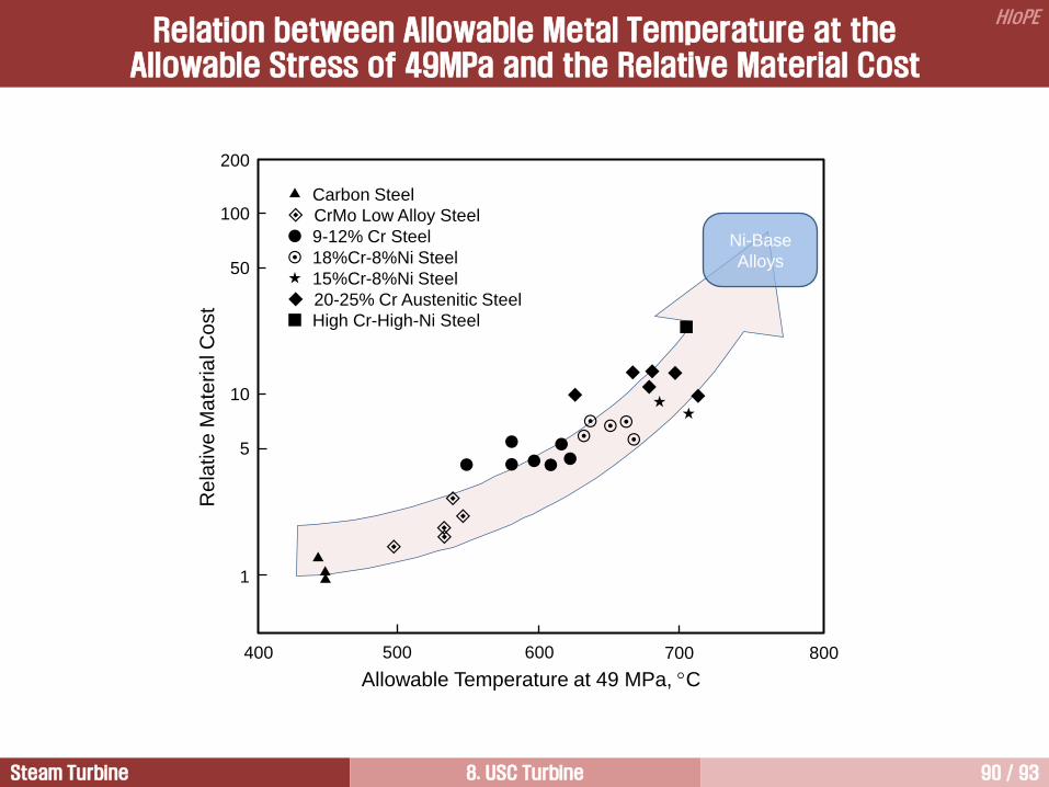
Carbon Steel
CrMo Low Alloy Steel
9-12% Cr Steel
18%Cr-8%Ni Steel
15%Cr-8%Ni Steel
20-25% Cr Austenitic Steel
High Cr-High-Ni Steel
Ni-Base
Alloys
Allowable Temperature at 49 MPa, C
Re
lative
Ma
teria
l C
ost
400 500 600 700 800
200
100
50
10
5
1
Relation between Allowable Metal Temperature at the Allowable Stress of 49MPa and the Relative Material Cost

Steam Turbine 8. USC Turbine 91 / 93
HIoPE
Alstom
Material Validation

Steam Turbine 8. USC Turbine 92 / 93
HIoPE
Nozzle box 12Cr cast steel
HP internal casing
12Cr cast steel
Main steam stop valves
12Cr cast steel
Main steam Inlet short pipe
9Cr-1Mo steel
Combined reheat steam valves
12Cr cast steel
Reheat steam inlet short pipes
9Cr-1Mo steel
No.1 IP internal casing
12Cr cast steel
HP IP
Main steam inlet flange elbow
9Cr-1Mo steel
Cooling structure with main steam leading pipe
Overlay coating Protection of No.s 1,2 journal thrust bearing
Rotor cooling for IP section (Protection of aged bending)
Control valves 12Cr cast steel
H-IP Combined Type 600゚C / 600C to 620゚C
Steam Temperature
HIP Rotor 12Cr steel
USC Materials
Hitachi

Steam Turbine 8. USC Turbine 93 / 93
HIoPE
질의 및 응답
작성자: 이 병 은 (공학박사) 작성일: 2015.02.11 (Ver.5) 연락처: [email protected]
Mobile: 010-3122-2262 저서: 실무 발전설비 열역학/증기터빈 열유체기술