8 - sensorsandrangemeasurementlanthier/teaching/comp4807/notes/8... · common types of sensors used...
TRANSCRIPT

dSensors and Range Measurement
Chapter 8Measurement

ObjectivesTo understand various types of sensors
To understand how common range sensors are used gin robotics
To understand the advantages and disadvantages of To understand the advantages and disadvantages of various range sensors
To briefly look at how stereo vision worksTo briefly look at how stereo vision works
To examine some results of combining sensors
8-2Winter 2012Chapter 8 – Sensors and Range Measurement
What’s in Here ?Sensors
Range Sensors– Tactile Sensors– Proximity Sensors
l iUltrasonic Range Sensors
IR Range Sensors
Laser Range Finders
Stereo Camera Ranging Systems
Sensor Selection
8-3Winter 2012Chapter 8 – Sensors and Range Measurement

SensorsSensors

SensingSensing is the sole way of obtaining environmental information.
A robot’s abilities (i.e., usefulness) depends on:– The quantity and quality of its sensorsq y q y– The ability and speed to process sensory input– The ability to act on what it perceives
The ability of a robot to become aware of its environment through sensing is called perception.
A robot must take in sensory input and then extract useful information from the data.
8-5Winter 2012Chapter 8 – Sensors and Range Measurement

SensorsRobots are equipped with a variety of different kinds of sensors so as to allow:
flexibility i type of data se sed (e g dista ce– flexibility in type of data sensed (e.g., distance,direction, light, sound, temperature, etc…)
– ability to combine sensor data to obtain more ability to combine sensor data to obtain more accurate representation of the world (e.g., light-based sensors cannot detect glass, whereas sonar can)
Use of multiple copies of certain sensors:– speeds up rate of environmental readings– provides redundancy for fault tolerance– saves power (e.g., robot may not have to rotate a sensor to
get a 360° reading)
8-6Winter 2012
get a 360 reading)
Chapter 8 – Sensors and Range Measurement

SensorsSensors vary in terms of: – size, weight, price, accuracy and precision.
Accuracy is the quality of “nearness” to the true value
Precision is the quality of being reproducible in amount or performance.
Store-bought sensors usually come with statistics that indicate the degree of accuracy and precision g y pthat the sensor is able to obtain.
8-7Winter 2012Chapter 8 – Sensors and Range Measurement

SensorsThere are two categories of sensors:
– PassiveSense the environment without altering it. (e.g., touch, heat, sound & light sensors, cameras)
– Active Alter the environment by sending out some kind of signal which is usually modified in some way by the environment and then detected again. (e.g., sonar, infrared, laser range finders)
8-8Winter 2012Chapter 8 – Sensors and Range Measurement

SensorsPassive sensors are often preferred over active sensors since they do not add extra signals or noise to the environments. to the environments.
Active sensors are sometimes preferred over passive sensors since they have less difficulty extracting sensors since they have less difficulty extracting relevant information.
P ssi e se s s e s ll p efe ed i lti b t Passive sensors are usually preferred in multi-robot environments since signals from active sensors can interfere with other robots.
8-9Winter 2012Chapter 8 – Sensors and Range Measurement

Sensor FusionTo account for inaccuracy, multiple sensor readings are often combined (or fused)
Sensor fusion combines sensor readings from:– Same sensor
Stereo Camera- Usually taken as an average, minimum or
maximum over small time intervalIR array
Stereo Camera
– Multiple similar kinds of sensors- Individual sensors read from different
directions (e.g. sonar ring)directions (e.g. sonar ring)
– Different kinds of sensors- e.g., combining sonar with IR and vision measurements
Sonar Ring
8-10Winter 2012
e.g., combining sonar with IR and vision measurements
Chapter 8 – Sensors and Range Measurement

SensorsThere is an endless number of sensors for a variety of purposes.
We are interested in looking at just a few of the common types of sensors used on mobile robots.
We will focus mainly on range sensors which reports the distance from the sensor to an object.
8-11Winter 2012Chapter 8 – Sensors and Range Measurement

Range SensorsRange Sensors

Range SensorsCommonly used range sensors in robotics:– Tactile and Proximity sensors
l i– Ultrasonic Sensors– IR Range Sensors– Laser Range Finders– Laser Range Finders– Vision Systems
Each varies i complexity size Each varies in complexity, size, weight, expense, accuracy, etc..
The detection range is defined as the maximum distance that the sensor can read reliably from.
8-13Winter 2012Chapter 8 – Sensors and Range Measurement

Tactile SensorsTactile sensors detect distance through physical contact and are usually in the form of:
– One or more bumpers– Two or more whiskers
They are usually set to detect obstacles at (or within) y ya fixed distance from the robot.
The detection range of bumpers is usually anywhere g f p lly yfrom 1mm to 2cm.
8-14Winter 2012Chapter 8 – Sensors and Range Measurement

Tactile SensorsWhiskers have a detection range that varies according to their length.
Good length
– Usually placed at front and extend long enough to ensure safe stopping distance Too long
– Should extend entire body width so as to detect successfully any obstacles.
Not wide enough
Tactile sensors have the tremendous advantage over all other sensors in that they are:+ simple - provide a binary signal (“yes” or “no” obstacle)+ trustworthy - simple things rarely break down.
8-15Winter 2012Chapter 8 – Sensors and Range Measurement

Tactile SensorsTactile sensors of course, do have their disadvantages:
- They provide only poor or coarse resolutiony p y p
- Bumpers require robot to make solid contact with obstacles (dangerous for obstacles + unhealthy for robot)
- Whiskers can become tangled or caught in cracks
- Whiskers oscillate when released after bending resulting in - Whiskers oscillate when released after bending, resulting in spurious readings until they settle again
- Whiskers may require mechanical adjustments or repairW iskers ay req ire ec a ical a j st e ts or repair
8-16Winter 2012Chapter 8 – Sensors and Range Measurement

Proximity SensorsProximity sensors are sensors that detect obstacles within a specific range from the robot.
Provide binary signal according to some threshold distance: obstacle “within range” or “out of range”.
Tactile sensors are examples of proximity sensors.
There are non tactile proximity sensorsThere are non-tactile proximity sensors.– e.g., encoders are examples of proximity sensors that
detect the absence or presence of a light reflectiondetect the absence or presence of a light reflection
Non-tactile proximity sensors are usually active.
8-17Winter 2012Chapter 8 – Sensors and Range Measurement

Proximity SensorsAny range sensor can be configured as a proximity sensor simply by setting a threshold
Proximity sensors operate using various mediums:– Light (infrared (IR))– Sound (ultrasonic)– Capacitance (electrostatic fields)
I d cta ce (ma etic fields)– Inductance (magnetic fields)
We will discuss capacitance and inductance first, then i e detail e a di li ht based a d s din more detail regarding light-based and sound-based sensors.
8-18Winter 2012Chapter 8 – Sensors and Range Measurement

CapaciflectorsCapacitance sensors (a.k.a. capaciflectors) detect change in capacitance around it.
– When power is applied to the sensor, an electrostatic field is generated and
t t h i it reacts to changes in capacitance caused by the presence of an obstacle.
Can detect obstacles from up to 46cm away from the platform.
8 capaciflectors on the
8-19Winter 2012Chapter 8 – Sensors and Range Measurement
pbottom on this robot.

CapaciflectorsAdvantages:+ lightweight, cheap, robust, fast obstacle detection
d i i f i f b l+ can detect proximity of various types of obstacleswithin some threshold range
Disadvantages: - Range estimate depends on dielectric constant of obstacle it is
sensing; the higher the dielectric constant the more sensitive sensing; the higher the dielectric constant, the more sensitive a capacitive sensor is to that obstacle.
- Different materials have different characteristics resulting in variety of range readings
- Cannot detect accurate distance unless obstacle material is known
8-20Winter 2012
known
Chapter 8 – Sensors and Range Measurement

Inductive Proximity SensorsInductive Sensors detect changes in magnetic fields caused by other objects within close range.
– Sensor generates magnetic field which induces Eddy currents in the object.
– The Eddy currents in the object magneticallypushes back and dampens inductive sensors’ oscillation field.
– sensor’s detection circuit monitors the dampening effect and h ti ff t b s s ffi i tl d d it t i s when magnetic effect becomes sufficiently damped, it triggers
the output circuitry.
8-21Winter 2012Chapter 8 – Sensors and Range Measurement

Inductive Proximity SensorsAdvantages:+ Very robust under hard/noisy conditions (industrial)
i hl+ Highly accurate+ Great for assembly lines and industrial applications
Disadvantages:- Very small detection range (0.0001in to 1in)
l k f i i f l bj- Only works for sensing certain types of metal objects.- Range measurement varies according to metal type.
These sensors are impractical for most mobile robot applications
8-22Winter 2012Chapter 8 – Sensors and Range Measurement

Ultrasonic Range SensorsUltrasonic Range Sensors

Ultrasonic Range SensorsUltrasonic Sensors emit a sound wave signal and measure the time it takes for that signal to be returned.– transducer emits and receives object
operating
Maximum sensing distance
ultrasonic signal. - incoming echo is checked, the time taken
for sound to travel the distance is determined
p grange
for sound to travel the distance is determinedand corresponding output signal is emitted.
– Blind zone exists Minimum sensing distance
- echo arrives before transducer isready to receive.
- objects in this dead band cannot be detected reliably
beamangle
blindzone
8-24Winter 2012
objects in this dead band cannot be detected reliably.
Chapter 8 – Sensors and Range Measurement

Ultrasonic Range SensorsShape of beam is not a simple wedge:
– wider objects near center of beam result in better accuracy– wider objects near center of beam result in better accuracy
8-25Winter 2012Chapter 8 – Sensors and Range Measurement

Ultrasonic Range SensorsReadings from sensor vary depending on:– distance to object(s)
l i l bj l i l- Multiple objects result in only one distance reading
l th t bj t k ith – angle that object makes with respect to sensor axis- smoother materials require perpendicular orientationsmoother materials require perpendicular orientation
– direction that object enters sensing range- smooth objects must enter from the smooth objects must enter from the
front with their surface perpendicularto produce proper reading.
8-26Winter 2012Chapter 8 – Sensors and Range Measurement

Ultrasonic Range SensorsSensitivity to obstacle angle can resultin improper range readings.
desired
When beam’s angle of incidence falls below a certain critical angle specular
range
measuredrangebelow a certain critical angle specular
reflection errors occur.range
Specular Reflection(smooth surfaces)
Diffuse Reflection(rough surfaces)
8-27Winter 2012Chapter 8 – Sensors and Range Measurement

Ultrasonic Range SensorsSpecular reflection can cause reflected sound to:– never return to the transducer
h d l– return to the transducer too late
In either case, the result is that the distance i l d imeasurement is too large and inaccurate
Distance returned represents Echo never returns resulting in total round-trip delay.Echo never returns, resulting in maximum distance reading.
8-28Winter 2012Chapter 8 – Sensors and Range Measurement

Ultrasonic Range SensorsDistance and angular resolution decreases as objects become further from sensor
multiple close obstacles ca ot be disti guished– multiple close obstacles cannot be distinguished– gaps cannot be detected (e.g., doorways)
doorwaydetected
doorway undetected detected
Sensor cannot distinguish between these three scenarios. I ll i l di t
undetected
In all cases, a single distance measurement is returned.
8-29Winter 2012
Chapter 8 – Sensors and Range Measurement

Ultrasonic Range SensorsTo increase beam width (i.e., resolution)two sensors are often used together.
only left
Detection of object in either or bothsensors allows for three detection
detects only right detects
both detect
sensors allows for three detectionwedges, increasing resolution.
i l i
better resolution
Typical sensor range is 15cm to 300cm
adjustable with ±0.1% accuracy Beam angle
usually
over entire range at stabletemperatures.
y15°
8-30Winter 2012Chapter 8 – Sensors and Range Measurement

Ultrasonic Range SensorsTo perform mapping, sonars (a.k.a. ultrasonic sensors) must take multiple readings:
– can simply rotate the robot body
t t ki d f h d d i– can rotate some kind of head device
– can use multiple sensors at fixed positions can use multiple sensors at fixed positions around robot body
8-31Winter 2012Chapter 8 – Sensors and Range Measurement

Ultrasonic Range SensorsUsing multiple fixed position sensors can lead to another problem called crosstalk:
A form of i terfere ce i which echoes emitted from o e – A form of interference in which echoes emitted from one sensor are detected by others
Some sensors may pick up echos from a previous sensor’s
Some sensors may pick up echos from a previous sensor’s emitted signal.emitted signal.
8-32Winter 2012Chapter 8 – Sensors and Range Measurement

Ultrasonic Range SensorsCrosstalk signals are impossible to detect– unless signals are somehow unique (e.g., coded)
Crosstalk can be reduced by carefully timing the emitting of signals
– emit from one and wait for a time interval
– emit from a selected few that will “likely”emit from a selected few that will likelyhave no interference (although there are no guarantees)
Gg
Group sonars into small groups that are allowed to emit signals at the same time.
8-33Winter 2012Chapter 8 – Sensors and Range Measurement

Ultrasonic Range SensorsAdvantages of ultrasonic range sensors:+ reliable with good precision
id i f+ not as prone to outside interference+ good maximum range+ inexpensive+ inexpensive
Disadvantages:i i h l b l- sensitive to smoothness & angle to obstacles
- poor resolution- prone to self-interference from echos- prone to self-interference from echos- cannot detect obstacles too close
8-34Winter 2012Chapter 8 – Sensors and Range Measurement

f dInfrared (IR)Range SensorsRange Sensors

IR Range SensorsInfrared Range Sensors emit a beam of infrared light and measure the amount of light being reflected from the obstacle.from the obstacle.
IR light beam is not visible
There are four main operational techniques:– Reflective (measures strength of light reflected from object)
– Transmissive (detects presence of object between emitter/detector)
– Modulated (modulates beam to reduce noise)
i l i l h li h i fl d f– Triangulation (measures angle that light is reflected from object)
8-36Winter 2012Chapter 8 – Sensors and Range Measurement

IR Range SensorsBasic IR proximity detection is simple– Turn on an IR diode (i.e., light)
i h i fl d ff b l li hobject
– Light is reflected off obstacle, some light returns– Receiver measures strength of light returned.
As with sonars, signal is highly dependenton reflective characteristics of the object.– shiny obstacles (e.g., metal) cause problems
Range depends on color of obstacleg p– white/black surfaces report different ranges– cannot detect glass
8-37Winter 2012Chapter 8 – Sensors and Range Measurement

IR Range SensorsModulated IR– Signal is rapidly-varied IR, usually via
fl hi l i ( kh )flashing or pulsing (e.g., 40khz)
– Receiver has additional circuitry so that it only responds to a matching modulated IR signal.
Helps reduce outside IR noise and interference with pother IR devices operating at different frequencies.
Multiple robots can be equipped with IR sensors p q ppoperating at different frequencies to avoid interference.
8-38Winter 2012Chapter 8 – Sensors and Range Measurement

IR Range SensorsTriangulated IR (e.g., Sharp GP2D12)– senses the angle at which the reflected IR
i d h
object
is returned to the sensor.
Receiver has lens that projects Angle is
returned IR light onto a CCD array objectsmaller when
object is closer
Receiver lens
CCD array(charge-coupled device)
Object at various positionsObject at various positions
8-39Winter 2012Chapter 8 – Sensors and Range Measurement

IR Range SensorsAs with sonars, the Sharp GP2D12 sensor cannot always distinguish features at far distances.
Consider test done bySharp as shown ontheir datasheets:
Measured voltages at specific points
8-40Winter 2012Chapter 8 – Sensors and Range Measurement

IR Range SensorsSharp produces many popular proximity detectors that vary according to their maximum and minimum distance ranges:minimum distance ranges:
Our DIRRS+ sensor
Our front and side IR sensors are not shown here but are similar to these, except that their threshold detection range is fixed at either 5cm or 10cm.
8-41Winter 2012Chapter 8 – Sensors and Range Measurement

IR Range SensorsThe distance vs. voltage graph shows non-linearity
InvalidInvalidInvalid sensing ranges
Invalid sensing ranges
somewhat logarithmic
Objects too close actually appear as
…
actually appear as far away objects.
Logarithmic shape varies slightly from one detector to another.
8-42Winter 2012Chapter 8 – Sensors and Range Measurement

IR Range SensorsClose objects (within 8cm) are within a dangerous collision range.
– Object may be detected at 12cm, but by the time the robot stops, the object is in the 6cm range…
– The robot would then detect it at 12cm again and think it is still far enough away from it.
C d thi bl b hi f th Can reduce this problem by pushing sensors further back on the robot(called cross-firing)(called cross firing)
8-43Winter 2012Chapter 8 – Sensors and Range Measurement

IR Range SensorsTriangulation technique provides improvements:
– better immunity to ambient light noisey g– indifferent to color variations
As with ultrasonic sensors, multiple IR sensors are As with ultrasonic sensors, multiple IR sensors are often used in an array or circular pattern to speed up gathering of range data
8-44Winter 2012Chapter 8 – Sensors and Range Measurement
IR Range SensorsAdvantages of IR range sensors:+ reliable with good precision
ll b l+ small beam angle+ inexpensive
Disadvantages:i i h l b l- sensitive to smoothness & angle to obstacles
- short range- prone to interference from ambient IR (e g outdoors)- prone to interference from ambient IR (e.g., outdoors)- can’t detect distance to glass, mirrors or shiny surfaces
8-45Winter 2012Chapter 8 – Sensors and Range Measurement
Laser Range FindersLaser Range Finders

Laser Range FindersLaser Range Finders are perhaps the most accurate sensors for measuring distances.
Similar concept to IR range finder in that IR light is emitted and detected.
These sensors are Lidar (Light Detection and Ranging) systemsand Ranging) systems
Lidar systems use one of three techniques:– Pulsed Modulation– Amplitude Modulation Continuous Wave (AMCW)
F q M d l ti C ti s W (FMCW)
8-47Winter 2012
– Frequency Modulation Continuous Wave (FMCW)
Chapter 8 – Sensors and Range Measurement

Laser Range FindersPulsed Modulation lidar system (e.g., Sick sensor)– emits a pulsed laser light beam
fl d li h i d d– reflected light is returned to detector– rotating mirrors are used to direct
outgoing and incoming light to perform up to 240° scanoutgoing and incoming light to perform up to 240 scan
Transmits pulse-modulated laser
Receives reflected pulse-modulated laser beam.
Beammodulated laser beam.
Beamsplitter
180° rotating mirror
Obstacles
8-48Winter 2012Chapter 8 – Sensors and Range Measurement

Laser Range FindersRange calculated as r = t x c / 2 where
t = time taken for light to return from when it was sent outd f li hc = speed of light ~= 300,000,000 m/sec
Must have VERY fast processing since return times llare very small.
This leads to high expense of sensor (> $6k US)g p
Tradeoff is high resolution … sometimes worth it.“Sick” sensor can scan 180° at 0 5° resolution – Sick sensor can scan 180 at 0.5 resolution with accuracy ±1.5cm in short range (1m - 8m) and ±4cm in long range (8m - 20m)
8-49Winter 2012
cm g g ( m m)
Chapter 8 – Sensors and Range Measurement

Laser Range Finders– “Hokuyo” sensor can scan 240° at 0.36°
resolution with accuracy ±1cm in range (2cm - 4m)
Typically measure ranges up to 50m
Scanning at multiple heights produces a set of Scanning at multiple heights produces a set of contour lines that can be stacked together to form model
Result of scan at single height level is a visibility polygony p yg
8-50Winter 2012Chapter 8 – Sensors and Range Measurement

Laser Range FindersFull 3D scenes are usually scanned in one shot:
Typically 180°Intensity Imageyp y
scan taken at various heightsvarious heightswith device mounted on R Dmounted onpivoting “head”.
Range Data
Can be very accurate.
8-51Winter 2012Chapter 8 – Sensors and Range Measurement

Laser Range FindersAMCW sensors– emitter sends out a continuous modulated laser signal (i.e.,
intensity of beam is modulated using some wave pattern (e g intensity of beam is modulated using some wave pattern (e.g., sin wave).
– detected light has same amplitude but phase shifted– difference in phase shift indicates range
θ
temitter
Range calculated as r = θc/4πf whereθ = phase shiftf = frequency of modulated signaldetector
8-52Winter 2012Chapter 8 – Sensors and Range Measurement

Laser Range FindersFMCW technique is simpler and hence lower cost
Resolution is limited by modulating frequencyy g q y
FMCW sensors similarly emit a continuous laser beam, but modulated now by frequencybeam, but modulated now by frequency.
– emitted signal is mixed with reflected signal.Res lt is diffe e ce i f eq e c– Result is difference in frequency
emitter
t
beat frequency
detectort
t
8-53Winter 2012Chapter 8 – Sensors and Range Measurement
t

Laser Range FindersAdvantages:
+ better resolution than ultrasonic, IR, camerasli bl+ very reliable
+ not as sensitive to lighting conditions as cameras
Disadvantages:- cannot identify mirrors and/or glass
i h ll h- more expensive than all other sensors- larger and heavier than all other sensors
8-54Winter 2012Chapter 8 – Sensors and Range Measurement

Laser Range Finder ExperimentsExperiments were done using the Hokuyo scanner combined with a webcamObj ti t dd d th t Objective: to add depth to a camera image by finding
f d i hsurfaces and separating themlike cardboard cutouts
Laser Scanner
Webcam
Servo Tilt System: allows scanner to make a3D scan to produce a 3D model.
8-55Winter 2012Chapter 8 – Sensors and Range Measurement

Experiment 1Computed angled view
Camera image
Computed side viewside view
8-56Winter 2012Chapter 8 – Sensors and Range Measurement

Experiment 2Computed angled view
Computed side view
CCamera image
8-57Winter 2012Chapter 8 – Sensors and Range Measurement

Experiment 3Computed side view
Computed angled view
Camera image
8-58Winter 2012Chapter 8 – Sensors and Range Measurement

Experiment 4Computed angled view
Camera imageimage
Computed side view
8-59Winter 2012Chapter 8 – Sensors and Range Measurement

Laser Range FindersWe will not discuss laser range finders any more in this course.
In terms of mapping, laser range finders are just high quality 3D versions of our simple IR sensors.
For the PropBot, we do not have the processing speed, power or size to accommodate such a sensor.p p
8-60Winter 2012Chapter 8 – Sensors and Range Measurement
Stereo CameraRanging SystemsRanging Systems

Stereo Ranging SystemsAs with laser range finders, robots equippedwith Stereo cameras can obtain 3D rangemaps of the environment.
Usually 2 cameras used, although A ~$2k stereo camera from Usually 2 cameras used, although
one can be used from multiple locations.
i l l i
ptgrey.com
Typical resolutions:– 640 x 480 at 30 frames per second
1024 768 t 30 f d– 1024 x 768 at 30 frames per second
Cameras cover roughly a 45° cone.
8-62Winter 2012Chapter 8 – Sensors and Range Measurement

Stereo Ranging SystemsGoal of stereo vision: – to calculate the depth or distance of features relative to the
sensor (i e to construct a depth map) sensor (i.e., to construct a depth map). • Uses images from dual cameras aimed at the same object. • Need to locate the “same” features in both images. • Using the geometrical relationship between the two cameras and
the location of the feature in each image, the depth of each feature can be triangulated and a depth map constructed.
Further objects appear darker
Some areas are black, indicating i bilit
Right ImageRight Image Left ImageLeft Image Depth MapDepth MapRight Image Left Image Depth Map
Closer objects appear brighter
inability to compute range.
8-63Winter 2012Chapter 8 – Sensors and Range Measurement
Right ImageRight Image Left ImageLeft Image Depth MapDepth MapRight Image Left Image Depth Map

Stereo Ranging SystemsPrinciple behind stereo vision:
– Objects seen in left camera appear j pphorizontally shifted from objectsseen in right camera.
– Size of shift, called the disparity, varies with object’s distance from the cameras.
– Central idea is to find acorrespondence (or match) between points in one image with points in other image (not easy to get right).
8-64Winter 2012Chapter 8 – Sensors and Range Measurement

Stereo Ranging SystemsFor each pixel in one image, finding the corresponding pixel in the other image is difficult
I stead fi d similarity (most likely match)– Instead, find similarity (most likely match).
In some cases, pixels in one image may simply not be visible i the other This is called occlusio visible in the other. This is called occlusion.
Can be due to closer obstacles hiding objects behind them at certain angles.
Can be due to unavailable data due to viewing region.
8-65Winter 2012Chapter 8 – Sensors and Range Measurement

Stereo Ranging SystemsIf cameras pointing in same direction and aligned, can use simple geometry:
ppb = baseline of camera system
(i.e., a fixed value) d th f i t
pp
z = depth of point pd = disparity = xl – xr
f = focal point of cameras
z z
f = focal point of cameras(i.e., a fixed value)
The two shaded triangles f
b
fg
are similar, and so z = f bf
d
f
dxl xr
8-66Winter 2012Chapter 8 – Sensors and Range Measurement

Stereo Ranging SystemsSo, the depth is inversely proportional to disparity– stereo is most accurate for close objects
Disparity is always an integer value since it is difference in x values of pixels.
Accuracy of depth can be increased by increasing baseline distance (i.e., distance between cameras)– but reduces overlap of cameras and hence scene width– more difficult to identify matching pairs of points
i l f i h i h l i dsince left/right images have less in common due to larger difference in viewing angle
8-67Winter 2012Chapter 8 – Sensors and Range Measurement

Stereo Ranging SystemsMore realistic scenario is when cameras are not lying on the same plane:
Z0 found during calibration, then remains fixed.
Here z ≈ f b
Objects have 0 disparity here
z f bz z0(d + (fb / z0))
b
f
8-68Winter 2012Chapter 8 – Sensors and Range Measurement

Stereo Ranging SystemsSo how do we compute correspondence ?
Some desired characteristics:– Corresponding image regions are similar– Each point matches a single point in the other image
• unlikely for low feature scenes (e.g. blank walls)
Many matching methods, 2 main types:y g yp– Feature-based - start from image structure (e.g., edges)– Correlation-based - start from grey levels
We will look a little at correlation-based methods
8-69Winter 2012Chapter 8 – Sensors and Range Measurement

CorrelationThere are many approaches to doing correlation, each providing different results:
Sum of Squared Differe ces (SSD)We will look more at this one only.– Sum of Squared Differences (SSD)
– Dynamic Programming (DP)– Graph Cut (GC) Id l l ti
y
Graph Cut (GC)– Belief Propagation (BP)– Markov Random Fields (MRF)
Ideal solution, manually computed
Left Image SSD DP GC Ground Truth
8-70Winter 2012Chapter 8 – Sensors and Range Measurement

SSD CorrelationIdea:– Take a small area of data in left image and compare it with
similar-sized areas in the right image along the same epipolar similar-sized areas in the right image along the same epipolar line (e.g., at the same height in the image if the cameras are horizontally level).
Search Window:Best Match
Check whole row
Left Image Right Image
8-71Winter 2012Chapter 8 – Sensors and Range Measurement

SSD CorrelationComparison is done by finding the sum of squared differences between left and right window areas.
M i diffFOR x = 0 to width DO {
FOR y = 0 to height DO {bestSSD = MAXINTFOR d = 0 to MAXRANGE DO {
ssd = 0
Maximum difference allowed during window comparison phase.
FOR xx = x –WINDOW_SIZE/2 to x+WINDOW_SIZE/2 DO {FOR yy = y –WINDOW_SIZE/2 to y+WINDOW_SIZE/2 DO {
diff = leftImage[xx, yy] – rightImage[xx+d, yy]ssd = ssd + (diff * diff)
}(x,y) position with least squared-
}IF (ssd < bestSSD) THEN {
bestSSD = ssdbestDisparity = d
}}
difference gives the best match, and hence the disparity of the best match
Window size is adjustable parameter. Large window
}disparityMap[x, y] = bestDisparity
}}
best match. means slower, but eliminates more noise.
8-72Winter 2012Chapter 8 – Sensors and Range Measurement

SSD Correlation3x3 19x1911x117x7
Window size20
Window size
Maximum disparity
50
100
left right
Red indicates no match
200
Smaller windows = more noise
8-73Winter 2012Chapter 8 – Sensors and Range Measurement
more noise

CorrelationThere are many strategies to improve matching:
– Apply various image filters before and after processingpp y g p g
– Identify corners and edges, hence planes (can help to fill-in areas in which no data is available).
– Use sensor fusion (i.e., data from other sensors) to fill-in missing gaps.
– Project structured light onto objects to improve matches:
8-74Winter 2012Chapter 8 – Sensors and Range Measurement

Stereo Ranging SystemsAdvantages:
+ better resolution than ultrasonic and IRli bl h i i ffi i l l d+ very reliable when environment is sufficiently cluttered.
+ often packaged with software to calculate depth
Disadvantages:- cannot identify mirrors and/or glass
i i li h i di i- sensitive to lighting conditions- poor performance when environment lacks features- more expensive than ultrasonic and IR- more expensive than ultrasonic and IR- larger that ultrasonic and IR- difficult to calibrate (depending on sensor packaging).
8-75Winter 2012
( p g p g g)
Chapter 8 – Sensors and Range Measurement

Scene ReconstuctionFrom depth maps, 3D models are often constructed by creating a triangular mesh.
Here is one with 2,860,000 vertices and over 5,000,000 triangles:
3D model from one angle 3D model from different angle Completed model
8-76Winter 2012Chapter 8 – Sensors and Range Measurement
3D model from one angle 3D model from different angle Completed model

Sensor SelectionSensor Selection

Sensor SelectionAs mentioned, range sensors each havetheir own advantages and disadvantages.
Certain factors must be considered when choosing an appropriate sensor:– cost and physical size of sensors– processing power required
b– environment (obstacle types, features, density, size…)
Certainly, different kinds of sensors can complimenthone another
8-78Winter 2012Chapter 8 – Sensors and Range Measurement

Popular ChoiceThe most popular choice for average-sized robots is the laser range finder, due to its high accuracy.
Vision-based sensors are also quite popular and share advantages with laser range finders:
– high accuracy and low cost/performance ratio
– 3D distance information
– high speed data acquisition
i h i i f i– rich in information
8-79Winter 2012Chapter 8 – Sensors and Range Measurement
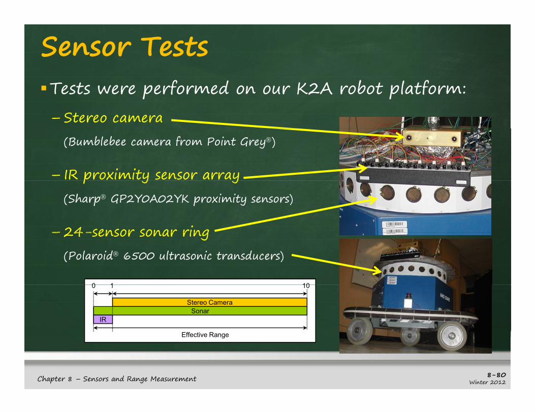
Sensor TestsTests were performed on our K2A robot platform:– Stereo camera
(Bumblebee camera from Point Grey®)
– IR proximity sensor arrayp y y(Sharp® GP2Y0A02YK proximity sensors)
– 24-sensor sonar ring– 24-sensor sonar ring(Polaroid® 6500 ultrasonic transducers)
0 1 10
Stereo CameraSonar
IR
0 1 10
Effective Range
8-80Winter 2012Chapter 8 – Sensors and Range Measurement
Effective Range

Sensor TestsTests were aimed at – determining the pitfalls of stereo cameras
i i i f d– investigating ways to merge 3 types of sensors to produce more accurate obstacle detection
5 Tests were performed5 Tests were performed:– Blank Wall – sensors aimed at a blank yellow wall– Low Lighting – sensors used in dark setting– Low Lighting – sensors used in dark setting– Low Contrast – sensors try to detect low contrast scene– Transparency – sensors try to detect glassp y y g– Full Lab – sensors operate around a typical lab
8-81Winter 2012Chapter 8 – Sensors and Range Measurement

Tests – Blank WallStereo Camera was unable to detect a featureless wall, whereas the IR and Sonar did detect them:
Wall
IR SONAR
Robot Data
When sufficient features were added tothe environment (a newspaper on the ( p pwall), the stereo camera did a little better: Stereo
Multiplerobot positions
8-82Winter 2012
better:
Chapter 8 – Sensors and Range Measurement

Tests – Low LightingSimilarly, stereo cameras performed poorly under low lighting:
Sonar detected many obstacles, but with coarse readings.
Stereo camera could not detect garbage can, nor walls.
8-83Winter 2012Chapter 8 – Sensors and Range Measurement

Tests – Low ContrastStereo camera had difficulty identifying range to uniform-color cabinet:
Only Only corners detected
Combined
IR accurate but requires many
Combined results
readings.
8-84Winter 2012Chapter 8 – Sensors and Range Measurement

Tests - TransparencyBoth stereo camera and IR had difficulty with glass:
Detected distances beyond glass
Sonar detects glass effectivelybeyond glass effectively
Detected distances beyond glass
Sensor fusion provides better estimate
8-85Winter 2012Chapter 8 – Sensors and Range Measurement

Tests – Full LabA more thorough test was done in our full lab:
Much noise fromstereo camera
Sonar correct but coarse
IR has lessIR has less readings due to short range
8-86Winter 2012Chapter 8 – Sensors and Range Measurement

Data Fusion59.7% of data comes from a single sensor
– considered to be noise
34.2% of data from 2 sensors
– considered to be valid readings
f d f ll6.2% of data from all 3 sensors
– may be considered “feature points”
8-87Winter 2012Chapter 8 – Sensors and Range Measurement
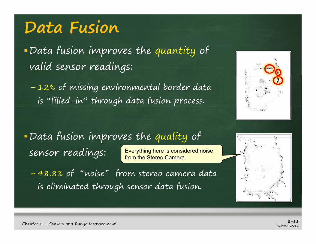
Data FusionData fusion improves the quantity of valid sensor readings:
– 12% of missing environmental border data is “filled-in” through data fusion process.
Data fusion improves the quality of Data fusion improves the quality of sensor readings: Everything here is considered noise
from the Stereo Camera.
– 48.8% of “noise” from stereo camera data is eliminated through sensor data fusion.
8-88Winter 2012Chapter 8 – Sensors and Range Measurement

Dynamic Sensor SelectionNo sensor outperforms any other in all situations
– cameras usually used to model complicated scenesy p
– sonar often used for rough/dynamic collision avoidance on larger robotsg
– IR typically used for collision avoidance, wall-following, mapping, etc… on smaller robotsfollowing, mapping, etc… on smaller robots
Some work has been done to dynamically select sensors over time:sensors over time:– can be based on learned information, known obstacle types or
known lighting conditions
8-89Winter 2012Chapter 8 – Sensors and Range Measurement

SummaryYou should now know about:– characteristics of various sensors
– advantages and disadvantages of various kinds of range and proximity sensors
– how ultrasonic and IR sensors work
– the concept behind laser range finders
– how to use a simple stereo vision algorithm
the issues behind choosing sensors– the issues behind choosing sensors
8-90Winter 2012Chapter 8 – Sensors and Range Measurement