7hfkqlfdo6shfl¿fdwlrq 5fdiojdbm4qfdjmdbujpo …
TRANSCRIPT

Limited Internal TABLE OF CONTENTS 1 (1)
Prepared (also subject responsible if other) No.
Stella TAO 00152-EN/LZT146350 Approved Checked Date Rev Reference
2006-6-19 A
Contents
General Information ............................................................. 2Safety Specification ............................................................. 3Absolute Maximum Ratings ............................................................. 4
Product Program Ordering No. 0.9-3.6 V/3 A PMD 4118O ........................................... 1.0 V/3 A Electrical Specification ............................................................. 5 1.2 V/3 A Electrical Specification ........................................................... 111.5 V/3 A Electrical Specification ........................................................... 171.8 V/3 A Electrical Specification ........................................................... 232.5 V/3 A Electrical Specification ........................................................... 293.3 V/3 A Electrical Specification ........................................................... 32
EMC Specification ........................................................... 35 Operating Information ........................................................... 35Thermal Consideration ........................................................... 37Connections ........................................................... 38Mechanical Information ........................................................... 39Soldering Information ........................................................... 41Delivery Information ........................................................... 43Product Qualification Specification ........................................................... 44
Ericsson Internal PRODUCT SPECIFICATION 1 (3)
Prepared (also subject responsible if other) No.
SEC/D Stella TAO 1/1301-BMR652 4 Uen Approved Checked Date Rev Reference
MPM/BY/M [Krister Lundberg] 2006-12-26 B
Key Features • 3A output current• 3 -5.5V input voltage range• Output voltages from 0.9V up to 3.6V• Industry standard POLATM compatible• 18.92 x 12.57 x 8.5 mm (0.745 x 0.495 x 0.335 in.)• High efficiency, up to. 94%• Auto TrackTM sequencing pin• More than 5.14 million hours MTBF
General Characteristics • Operating temperature: -40oC to 85 oC• Output short-circuit protection• Over temperature protection• On/Off inhibit control• Highly automated manufacturing ensures quality• ISO 9001/14001 certified supplier Safety Approvals Design for Environment
Pending Meets requirements in high-temperature lead-free soldering processes.
E
PMD 4000 seriesPOL regulator, Input 3.0-5.5 V, Output 3 A/10.8 W
EN/LZT 146 350 R1D Dec 2006
© Ericsson Power Modules AB
Technical Specifi cation
E
PMD 4000 seriesPOL regulator, Input 3.0-5.5 V, Output 3 A/10.8 W
EN/LZT 146 350 R1E Jan 2009
© Ericsson Power Modules AB
Technical Specifi cation
PMD 4000 series PoL Regulators Input 3.0-5.5 V, Output 3 A / 10.8 W
1/ 28701- BMR 652 Rev. A November 2017
© Flex
Technical Specification

Ericsson Internal PRODUCT SPECIFICATION 2 (3)
Prepared (also subject responsible if other) No.
SEC/D Stella TAO 1/1301-BMR652 4 Uen Approved Checked Date Rev Reference
MPM/BY/M [Krister Lundberg] 2006-12-26 B
General Information
Ordering Information
See Contents for individual product ordering numbers.
Option Suffix Ordering No.Through hole pin SMD pin SMD pin, leadfree reflow temperature capable
P S
SR
PMD 4118O WP PMD 4118O WS
PMD 4118O WSR
Reliability
The Mean Time Between Failure (MTBF) is calculated at full output power and an operating ambient temperature (TA) of +40°C, which is a typical condition in Information andCommunication Technology (ICT) equipment. Differentmethods could be used to calculate the predicted MTBFand failure rate which may give different results. Flex currently uses Telcordia SR332.
Predicted MTBF for the series is: - 5.14 million hours according to Telcordia SR332, issue
1, Black box technique.
Telcordia SR332 is a commonly used standard method intended for reliability calculations in ICT equipment. The parts count procedure used in this method was originally modelled on the methods from MIL-HDBK-217F, Reliability Predictions of Electronic Equipment. It assumes that no reliability data is available on the actual units and devices for which the predictions are to be made, i.e. all predictions are based on generic reliability parameters.
Compatibility with RoHS requirements
The products are compatible with the relevant clauses and requirements of the RoHS directive 2011/65/EU and have a maximum concentration value of 0.1% by weight in homogeneous materials for lead, mercury, hexavalent chromium, PBB and PBDE and of 0.01% by weight in homogeneous materials for cadmium.
Exemptions in the RoHS directive utilized in Flex products are found in the Statement of Compliance document.
Flex fulfills and will continuously fulfill all its obligations under regulation (EC) No 1907/2006 concerning the registration, evaluation, authorization and restriction of chemicals (REACH) as they enter into force and is through product materials declarations preparing for the obligations to communicate information on substances in the products.
Quality Statement
The products are designed and manufactured in an industrial environment where quality systems and methods like ISO 9000, 6σ (sigma), and SPC are intensively in use to boost the continuous improvements strategy. Infant mortality or early failures in the products are screened out and they are subjected to an ATE-based final test. Conservative design rules, design reviews and product qualifications, plus the high competence of an engaged work force, contribute to the high quality of our products.
Warranty
Warranty period and conditions are defined in Flex General Terms and Conditions of Sale.
Limitation of Liability
Flex does not make any other warranties, expressed or implied including any warranty of merchantability or fitness for a particular purpose (including, but not limited to, use in life support applications, where malfunctions of product can cause injury to a person’s health or life).
© Flex 2017The information and specifications in this technical specification is believed to be correct at the time of publication. However, no liability is accepted for inaccuracies, printing errors or for any consequences thereof. Flex reserves the right to change thecontents of this technical specification at any time without prior notice.
E
PMD 4000 seriesPOL regulator, Input 3.0-5.5 V, Output 3 A/10.8 W
EN/LZT 146 350 R1D Dec 2006
© Ericsson Power Modules AB
Technical Specifi cation
E
PMD 4000 seriesPOL regulator, Input 3.0-5.5 V, Output 3 A/10.8 W
EN/LZT 146 350 R1E Jan 2009
© Ericsson Power Modules AB
Technical Specifi cation
PMD 4000 series PoL Regulators Input 3.0-5.5 V, Output 3 A / 10.8 W
1/ 28701- BMR 652 Rev. A November 2017
© Flex
Technical Specification 2

Ericsson Internal PRODUCT SPECIFICATION 3 (3)
Prepared (also subject responsible if other) No.
SEC/D Stella TAO 1/1301-BMR652 4 Uen Approved Checked Date Rev Reference
MPM/BY/M [Krister Lundberg] 2006-12-26 B
Safety Specification
General information Flex DC/DC converters and DC/DC regulators are designed in accordance with safety standards IEC/EN/UL60950, Safety of Information Technology Equipment.
IEC/EN/UL60950 contains requirements to prevent injury or damage due to the following hazards:
• Electrical shock• Energy hazards• Fire• Mechanical and heat hazards• Radiation hazards• Chemical hazards
On-board DC-DC converters are defined as component power supplies. As components they cannot fully comply with the provisions of any Safety requirements without “Conditions of Acceptability”. It is the responsibility of the installer to ensure that the final product housing these components complies with the requirements of all applicable Safety standards and Directives for the final product.
Component power supplies for general use should comply with the requirements in IEC60950, EN60950 and UL60950 “Safety of information technology equipment”.
There are other more product related standards, e.g. IEEE802.3af “Ethernet LAN/MAN Data terminal equipment power”, and ETS300132-2 “Power supply interface at the input to telecommunications equipment; part 2: DC”, but all of these standards are based on IEC/EN/UL60950 with regards to safety.
Flex DC/DC converters and DC/DC regulators are UL60950 recognized and certified in accordance with EN60950.
The flammability rating for all construction parts of the products meets requirements for V-0 class material according to IEC 60695-11-10.
The products should be installed in the end-use equipment, in accordance with the requirements of the ultimate application. Normally the output of the DC/DC converter is considered as SELV (Safety Extra Low Voltage) and the input source must be isolated by minimum Double or Reinforced Insulation from the primary circuit (AC mains) in accordance with IEC/EN/UL60950.
Non-isolated DC/DC regulators The input voltage to the DC/DC regulator is SELV (Safety Extra Low Voltage) and the output remains SELV under normal and abnormal operating conditions.
E
PMD 4000 seriesPOL regulator, Input 3.0-5.5 V, Output 3 A/10.8 W
EN/LZT 146 350 R1D Dec 2006
© Ericsson Power Modules AB
Technical Specifi cation
E
PMD 4000 seriesPOL regulator, Input 3.0-5.5 V, Output 3 A/10.8 W
EN/LZT 146 350 R1E Jan 2009
© Ericsson Power Modules AB
Technical Specifi cation
PMD 4000 series PoL Regulators Input 3.0-5.5 V, Output 3 A / 10.8 W
1/ 28701- BMR 652 Rev. A November 2017
© Flex
Technical Specification 3

Limited Internal PRODUCT SPEC. 1 (31)
Prepared (also subject responsible if other) No.
EGUHAIL 2/1301-BMR 6524 Uen Approved Checked Date Rev Reference
SEC/D (Julia You) ESHUHAN 2008-11-27 C
Absolute Maximum Ratings
Characteristics min typ max Unit
Tamb Operating Temperature (see Thermal Consideration section) 40 85 °C
TS Storage temperature 40 125 °C
VI Input voltage 3.0 3.3/5.0 5.5(1) V
Positive logic option VI -0.5 Open V Vinh Inhibit On/Off pin voltage (see Operating Information section) Negative logic option N/A N/A V
Stress in excess of Absolute Maximum Ratings may cause permanent damage. Absolute Maximum Ratings, sometimes referred to as no destruction limits, are normally tested with one parameter at a time exceeding the limits of Output data or Electrical Characteristics. If exposed to stress above these limits, function and performance may degrade in an unspecified manner. Note 1: For input voltage between 3.0-4.4 V, the output adjust range is limited to 0.9- (vI -1.1) V.
Fundamental Circuit Diagram
E
PMD 4000 seriesPOL regulator, Input 3.0-5.5 V, Output 3 A/10.8 W
EN/LZT 146 350 R1E Jan 2009
© Ericsson Power Modules AB
Technical Specifi cation
PMD 4000 series PoL Regulators Input 3.0-5.5 V, Output 3 A / 10.8 W
1/ 28701- BMR 652 Rev. A November 2017
© Flex
Technical Specification 4

Limited Internal PRODUCT SPEC. 2 (31)
Prepared (also subject responsible if other) No.
SEC/D KEVIN YAN 2/1301-BMR 652 4 Uen Approved Checked Date Rev Reference
SEC/D Julia You ESECZHW 2006-12-26 B
1.0 V/3 A Electrical Specification PMD 4118O
Tref = -40 to +85ºC, VI = 3.0 to 5.5 V, Radj = 84.5 kΩ, unless otherwise specified under Conditions. Typical values given at: Tref = +25°C, VI = 3.3/5.0 V, max IO , unless otherwise specified under Conditions. Additional Cin= 47µF and Cout= 47µF. See Operating Information section for selection of capacitor types. Connect the sense pin, where available, to the output pin. Characteristics Conditions min typ max Unit VI Input voltage range 3.0 5.5 V
VI = increasing 2.95 3 UVLO Undervoltage lockout
VI = decreasing 2.7 2.8 V
CI Internal input capacitance 22 µF
PO Output power 0 3.0 W
50 % of max IO 81.8 VI = 3.3 V
max IO 74.2
50 % of max IO 82.1 η Efficiency
VI = 5.0 V max IO 76.1
%
VI = 3.3 V, max IO 1.0 Pd Power Dissipation
VI = 5.0 V, max IO 0.9 W
IO = 0, VI = 3.3 V 70 Pli Input idling power
IO = 0, VI = 5.0 V 100 mW
VI = 3.3 V (turned off with INHIBIT) 3.3 Pinh Input standby power
VI = 5.0 V (turned off with INHIBIT) 5.0 mW
VI = 3.3 V, max IO 1.2 IS Static Input current
VI = 5.0 V, max IO 0.8 A
fs Switching frequency 0-100 % of max IO 700 kHz
VOi Output voltage initial setting and accuracy
Tref = +25°C, VI = 5.0 V, max IO 0.980 1.000 1.020 V
Output voltage tolerance band 10-100 % of max IO 0.970 1.030 V
IO = 0, VI = 3.3 V 1.003 Idling voltage
IO = 0, VI = 5.0 V 1.003 V
Line regulation max IO ±1 mV
VO
Load regulation VI = 3.3/5.0 V, 0-100 % of max IO ±5 mV
VI = 3.3 V, Load step 50-100-50 % of max IO, di/dt = 1 A/µs, see Note 1
±80
Vtr Load transient voltage deviation VI = 5.0 V, Load step 50-100-50 %
of max IO, di/dt = 1 A/µs, see Note 1
±60
mV
VI = 3.3 V, Load step 50-100-50 % of max IO, di/dt = 1 A/µs, see Note 1
110
ttr Load transient recovery time VI = 5.0 V, Load step 50-100-50 % of max IO, di/dt = 1 A/µs, see Note 1
90
µS
VI = 3.3 V, max IO 7.1 tr
Ramp-up time (from 10−90 % of VOi) VI = 5.0 V, max IO 6.8
ms
VI = 3.3 V, max IO 12.8 ts
Start-up time (from VI connection to 90 % of VOi) VI = 5.0 V, max IO 12.5
ms
E
PMD 4000 seriesPOL regulator, Input 3.0-5.5 V, Output 3 A/10.8 W
EN/LZT 146 350 R1D Dec 2006
© Ericsson Power Modules AB
Technical Specifi cation
E
PMD 4000 seriesPOL regulator, Input 3.0-5.5 V, Output 3 A/10.8 W
EN/LZT 146 350 R1E Jan 2009
© Ericsson Power Modules AB
Technical Specifi cation
PMD 4000 series PoL Regulators Input 3.0-5.5 V, Output 3 A / 10.8 W
1/ 28701- BMR 652 Rev. A November 2017
© Flex
Technical Specification 5

Limited Internal PRODUCT SPEC. 3 (31)
Prepared (also subject responsible if other) No.
SEC/D KEVIN YAN 2/1301-BMR 652 4 Uen Approved Checked Date Rev Reference
SEC/D Julia You ESECZHW 2006-12-26 B
Characteristics Conditions min typ max Unit Max IO 50 µS
VI = 3.3 V IO = 0.3 A 300 µS
Max IO 80 µS tf
Ramp-down time (from 90−10 % of VOi) VI = 5.0 V
IO = 0.3 A 300 µS
VI = 3.3 V, Max IO 18.3 INHIBIT start-up time
VI = 5.0 V, Max IO 16.9 ms
Max IO 120 µS VI = 3.3 V
IO = 0.3 A 140 µS
Max IO 140 µS
Tinh INHIBIT shutdown fall time (From INHIBIT off to 10 % of VO)
VI = 5.0 V IO = 0.3 A 160 µS
IO Output current 0 3 A
Ilim Current limit threshold Tref < max Tref, 7 A
VOac Output ripple & noise See ripple & noise section, max IO, VOi
10 mVp-p
Note 1: Output filter according to Ripple & Noise section
E
PMD 4000 seriesPOL regulator, Input 3.0-5.5 V, Output 3 A/10.8 W
EN/LZT 146 350 R1D Dec 2006
© Ericsson Power Modules AB
Technical Specifi cation
E
PMD 4000 seriesPOL regulator, Input 3.0-5.5 V, Output 3 A/10.8 W
EN/LZT 146 350 R1E Jan 2009
© Ericsson Power Modules AB
Technical Specifi cation
PMD 4000 series PoL Regulators Input 3.0-5.5 V, Output 3 A / 10.8 W
1/ 28701- BMR 652 Rev. A November 2017
© Flex
Technical Specification 6

Limited Internal PRODUCT SPEC. 4 (31)
Prepared (also subject responsible if other) No.
SEC/D KEVIN YAN 2/1301-BMR 652 4 Uen Approved Checked Date Rev Reference
SEC/D Julia You ESECZHW 2006-12-26 B
1.0 V/3 A Typical Characteristics (VI = 3.0-3.3 V) PMD 4118O
Efficiency Power Dissipation
70
75
80
85
90
95
100
0 1 2 3 4 [A]
[%]
3.3 V
3.0 V
0.0
0.5
1.0
1.5
2.0
0 1 2 3 4 [A]
[W]
3.3 V
3.0 V
Efficiency vs. load current and input voltage at Tref = +25°C Dissipated power vs. load current and input voltage at Tref = +25°C
Output Current Derating Output Characteristics
0
1
2
3
4
0 20 40 60 80 [°C]
[A]
2.0 m/s
Nat. Conv.
1.0 m/s
0.90
0.95
1.00
1.05
1.10
0 1 2 3 4 [A]
[V]
3.3 V
3.0 V
Available load current vs. ambient air temperature and airflow at VI = 3.3 V, VOUT = 2.0 V. See Thermal Consideration section.
Output voltage vs. load current at Tref = +25°C
E
PMD 4000 seriesPOL regulator, Input 3.0-5.5 V, Output 3 A/10.8 W
EN/LZT 146 350 R1D Dec 2006
© Ericsson Power Modules AB
Technical Specifi cation
E
PMD 4000 seriesPOL regulator, Input 3.0-5.5 V, Output 3 A/10.8 W
EN/LZT 146 350 R1E Jan 2009
© Ericsson Power Modules AB
Technical Specifi cation
PMD 4000 series PoL Regulators Input 3.0-5.5 V, Output 3 A / 10.8 W
1/ 28701- BMR 652 Rev. A November 2017
© Flex
Technical Specification 7

Limited Internal PRODUCT SPEC. 5 (31)
Prepared (also subject responsible if other) No.
SEC/D KEVIN YAN 2/1301-BMR 652 4 Uen Approved Checked Date Rev Reference
SEC/D Julia You ESECZHW 2006-12-26 B
1.0 V/3 A Typical Characteristics (VI = 5.0-5.5 V) PMD 4118O
Efficiency Power Dissipation
70
75
80
85
90
95
100
0 1 2 3 4 [A]
[%]
5.0 V
5.5 V
0.0
0.5
1.0
1.5
2.0
0 1 2 3 4 [A]
[W]
5.0 V
5.5 V
Efficiency vs. load current and input voltage at Tref = +25°C Dissipated power vs. load current and input voltage at Tref = +25°C
Output Current Derating Output Characteristics
0
1
2
3
4
0 20 40 60 80 [°C]
[A]
2.0 m/s
Nat. Conv.
1.0 m/s
0.90
0.95
1.00
1.05
1.10
0 1 2 3 4 [A]
[V]
5.0 V
5.5 V
Available load current vs. ambient air temperature and airflow at VI = 3.3 V, VOUT = 2.0 V. See Thermal Consideration section.
Output voltage vs. load current at Tref = +25°C
E
PMD 4000 seriesPOL regulator, Input 3.0-5.5 V, Output 3 A/10.8 W
EN/LZT 146 350 R1D Dec 2006
© Ericsson Power Modules AB
Technical Specifi cation
E
PMD 4000 seriesPOL regulator, Input 3.0-5.5 V, Output 3 A/10.8 W
EN/LZT 146 350 R1E Jan 2009
© Ericsson Power Modules AB
Technical Specifi cation
PMD 4000 series PoL Regulators Input 3.0-5.5 V, Output 3 A / 10.8 W
1/ 28701- BMR 652 Rev. A November 2017
© Flex
Technical Specification 8

Limited Internal PRODUCT SPEC. 6 (31)
Prepared (also subject responsible if other) No.
SEC/D KEVIN YAN 2/1301-BMR 652 4 Uen Approved Checked Date Rev Reference
SEC/D Julia You ESECZHW 2006-12-26 B
1.0 V/3 A Typical Characteristics (VI = 3.3 V) PMD 4118O
Start-up Shut-down
Start-up enabled by connecting VI at: Tref = +25°C, IO = 3 A resistive load, VI = 3.3 V.
Top trace: output voltage (1.0 V/div.). Bottom trace: input voltage (2.0 V/div.). Time scale: 10 ms/div.
Shut-down enabled by disconnecting VI at: Tref = +25°C, IO = 3 A resistive load, VI = 3.3 V.
Top trace: output voltage (1.0 V/div.). Time scale: 10 ms/div.
Output Ripple & Noise Output Load Transient Response
Output voltage ripple (5 mV/div.) at: Tref = +25°C, IO = 3 A resistive load, VI = 3.3 V. Time scale: 2 µs/div.
See the filter in the Output ripple and noise section (EMC Specification).
Output voltage response to load current step-change (1.5-3-1.5 A) at: Tref =+25°C, VI = 3.3 V.
Top trace: output voltage (100 mV/div.). Bottom trace: load current (1.5 A/div.). Time scale: 0.1 ms/div.
E
PMD 4000 seriesPOL regulator, Input 3.0-5.5 V, Output 3 A/10.8 W
EN/LZT 146 350 R1D Dec 2006
© Ericsson Power Modules AB
Technical Specifi cation
E
PMD 4000 seriesPOL regulator, Input 3.0-5.5 V, Output 3 A/10.8 W
EN/LZT 146 350 R1E Jan 2009
© Ericsson Power Modules AB
Technical Specifi cation
PMD 4000 series PoL Regulators Input 3.0-5.5 V, Output 3 A / 10.8 W
1/ 28701- BMR 652 Rev. A November 2017
© Flex
Technical Specification 9
Limited Internal PRODUCT SPEC. 7 (31)
Prepared (also subject responsible if other) No.
SEC/D KEVIN YAN 2/1301-BMR 652 4 Uen Approved Checked Date Rev Reference
SEC/D Julia You ESECZHW 2006-12-26 B
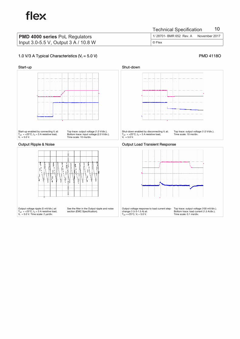
1.0 V/3 A Typical Characteristics (VI = 5.0 V) PMD 4118O
Start-up Shut-down
Start-up enabled by connecting VI at: Tref = +25°C, IO = 3 A resistive load, VI = 5.0 V.
Top trace: output voltage (1.0 V/div.). Bottom trace: input voltage (2.0 V/div.). Time scale: 10 ms/div.
Shut-down enabled by disconnecting VI at: Tref = +25°C, IO = 3 A resistive load, VI = 5.0 V.
Top trace: output voltage (1.0 V/div.). Time scale: 10 ms/div.
Output Ripple & Noise Output Load Transient Response
Output voltage ripple (5 mV/div.) at: Tref = +25°C, IO = 3 A resistive load, VI = 5.0 V. Time scale: 2 µs/div.
See the filter in the Output ripple and noise section (EMC Specification).
Output voltage response to load current step-change (1.5-3-1.5 A) at: Tref =+25°C, VI = 5.0 V.
Top trace: output voltage (100 mV/div.). Bottom trace: load current (1.5 A/div.). Time scale: 0.1 ms/div.
E
PMD 4000 seriesPOL regulator, Input 3.0-5.5 V, Output 3 A/10.8 W
EN/LZT 146 350 R1D Dec 2006
© Ericsson Power Modules AB
Technical Specifi cation
E
PMD 4000 seriesPOL regulator, Input 3.0-5.5 V, Output 3 A/10.8 W
EN/LZT 146 350 R1E Jan 2009
© Ericsson Power Modules AB
Technical Specifi cation
PMD 4000 series PoL Regulators Input 3.0-5.5 V, Output 3 A / 10.8 W
1/ 28701- BMR 652 Rev. A November 2017
© Flex
Technical Specification 10

Limited Internal PRODUCT SPEC. 8 (31)
Prepared (also subject responsible if other) No.
SEC/D KEVIN YAN 2/1301-BMR 652 4 Uen Approved Checked Date Rev Reference
SEC/D Julia You ESECZHW 2006-12-26 B
1.2 V/3 A Electrical Specification PMD 4118O
Tref = -40 to +85ºC, VI = 3.0 to 5.5 V, Radj = 26.1 kΩ, unless otherwise specified under Conditions. Typical values given at: Tref = +25°C, VI = 3.3/5.0 V, max IO , unless otherwise specified under Conditions. Additional Cin= 47µF and Cout= 47µF. See Operating Information section for selection of capacitor types. Connect the sense pin, where available, to the output pin. Characteristics Conditions min typ max Unit VI Input voltage range 3.0 5.5 V
VI = increasing 2.95 3 UVLO Undervoltage lockout
VI = decreasing 2.7 2.8 V
CI Internal input capacitance 22 µF
PO Output power 0 3.6 W
50 % of max IO 84.2 VI = 3.3 V
max IO 77.4
50 % of max IO 84.1 η Efficiency
VI = 5.0 V max IO 79.0
%
VI = 3.3 V, max IO 1.1 Pd Power Dissipation
VI = 5.0 V, max IO 1.0 W
IO = 0, VI = 3.3 V 75 Pli Input idling power
IO = 0, VI = 5.0 V 120 mW
VI = 3.3 V (turned off with INHIBIT) 3.3 Pinh Input standby power
VI = 5.0 V (turned off with INHIBIT) 5.0 mW
VI = 3.3 V, max IO 1.4 IS Static Input current
VI = 5.0 V, max IO 0.9 A
fs Switching frequency 0-100 % of max IO 700 kHz
VOi Output voltage initial setting and accuracy
Tref = +25°C, VI = 5.0 V, max IO 1.176 1.200 1.224 V
Output voltage tolerance band 10-100 % of max IO 1.164 1.236 V
IO = 0, VI = 3.3 V 1.206 Idling voltage
IO = 0, VI = 5.0 V 1.206 V
Line regulation max IO ±1 mV
VO
Load regulation VI = 3.3/5.0 V, 0-100 % of max IO ±5 mV
VI = 3.3 V, Load step 50-100-50 % of max IO, di/dt = 1 A/µs, see Note 1
±85
Vtr Load transient voltage deviation VI = 5.0 V, Load step 50-100-50 %
of max IO, di/dt = 1 A/µs, see Note 1
±60
mV
VI = 3.3 V, Load step 50-100-50 % of max IO, di/dt = 1 A/µs, see Note 1
120
ttr Load transient recovery time VI = 5.0 V, Load step 50-100-50 % of max IO, di/dt = 1 A/µs, see Note 1
110
µS
VI = 3.3 V, max IO 7.0 tr
Ramp-up time (from 10−90 % of VOi) VI = 5.0 V, max IO 6.7
ms
VI = 3.3 V, max IO 12.6 ts
Start-up time (from VI connection to 90 % of VOi) VI = 5.0 V, max IO 12.5
ms
E
PMD 4000 seriesPOL regulator, Input 3.0-5.5 V, Output 3 A/10.8 W
EN/LZT 146 350 R1D Dec 2006
© Ericsson Power Modules AB
Technical Specifi cation
E
PMD 4000 seriesPOL regulator, Input 3.0-5.5 V, Output 3 A/10.8 W
EN/LZT 146 350 R1E Jan 2009
© Ericsson Power Modules AB
Technical Specifi cation
PMD 4000 series PoL Regulators Input 3.0-5.5 V, Output 3 A / 10.8 W
1/ 28701- BMR 652 Rev. A November 2017
© Flex
Technical Specification 11

Limited Internal PRODUCT SPEC. 9 (31)
Prepared (also subject responsible if other) No.
SEC/D KEVIN YAN 2/1301-BMR 652 4 Uen Approved Checked Date Rev Reference
SEC/D Julia You ESECZHW 2006-12-26 B
Characteristics Conditions min typ max Unit Max IO 50 µS
VI = 3.3 V IO = 0.3 A 340 µS
Max IO 60 µS tf
Ramp-down time (from 90−10 % of VOi) VI = 5.0 V
IO = 0.3 A 350 µS
VI = 3.3 V, Max IO 18.4 INHIBIT start-up time
VI = 5.0 V, Max IO 16.9 ms
Max IO 100 µS VI = 3.3 V
IO = 0.3 A 130 µS
Max IO 160 µS
Tinh INHIBIT shutdown fall time (From INHIBIT off to 10 % of VO)
VI = 5.0 V IO = 0.3 A 180 µS
IO Output current 0 3 A
Ilim Current limit threshold Tref < max Tref, 7 A
VOac Output ripple & noise See ripple & noise section, max IO, VOi
10 mVp-p
Note 1: Output filter according to Ripple & Noise section
E
PMD 4000 seriesPOL regulator, Input 3.0-5.5 V, Output 3 A/10.8 W
EN/LZT 146 350 R1D Dec 2006
© Ericsson Power Modules AB
Technical Specifi cation
E
PMD 4000 seriesPOL regulator, Input 3.0-5.5 V, Output 3 A/10.8 W
EN/LZT 146 350 R1E Jan 2009
© Ericsson Power Modules AB
Technical Specifi cation
PMD 4000 series PoL Regulators Input 3.0-5.5 V, Output 3 A / 10.8 W
1/ 28701- BMR 652 Rev. A November 2017
© Flex
Technical Specification 12

Limited Internal PRODUCT SPEC. 10 (31)
Prepared (also subject responsible if other) No.
SEC/D KEVIN YAN 2/1301-BMR 652 4 Uen Approved Checked Date Rev Reference
SEC/D Julia You ESECZHW 2006-12-26 B
1.2 V/3 A Typical Characteristics (VI = 3.0-3.3 V) PMD 4118O
Efficiency Power Dissipation
70
75
80
85
90
95
100
0 1 2 3 4 [A]
[%]
3.3 V
3.0 V
0.0
0.5
1.0
1.5
2.0
0 1 2 3 4 [A]
[W]
3.3 V
3.0 V
Efficiency vs. load current and input voltage at Tref = +25°C Dissipated power vs. load current and input voltage at Tref = +25°C
Output Current Derating Output Characteristics
0
1
2
3
4
0 20 40 60 80 [°C]
[A]
2.0 m/s
Nat. Conv.
1.0 m/s
1.10
1.15
1.20
1.25
1.30
0 1 2 3 4 [A]
[V]
3.3 V
3.0 V
Available load current vs. ambient air temperature and airflow at VI = 3.3 V, VOUT = 2.0 V. See Thermal Consideration section.
Output voltage vs. load current at Tref = +25°C
E
PMD 4000 seriesPOL regulator, Input 3.0-5.5 V, Output 3 A/10.8 W
EN/LZT 146 350 R1D Dec 2006
© Ericsson Power Modules AB
Technical Specifi cation
E
PMD 4000 seriesPOL regulator, Input 3.0-5.5 V, Output 3 A/10.8 W
EN/LZT 146 350 R1E Jan 2009
© Ericsson Power Modules AB
Technical Specifi cation
PMD 4000 series PoL Regulators Input 3.0-5.5 V, Output 3 A / 10.8 W
1/ 28701- BMR 652 Rev. A November 2017
© Flex
Technical Specification 13

Limited Internal PRODUCT SPEC. 11 (31)
Prepared (also subject responsible if other) No.
SEC/D KEVIN YAN 2/1301-BMR 652 4 Uen Approved Checked Date Rev Reference
SEC/D Julia You ESECZHW 2006-12-26 B
1.2 V/3 A Typical Characteristics (VI = 5.0-5.5 V) PMD 4118O
Efficiency Power Dissipation
70
75
80
85
90
95
100
0 1 2 3 4 [A]
[%]
5.0 V
5.5 V
0.0
0.5
1.0
1.5
2.0
0 1 2 3 4 [A]
[W]
5.0 V
5.5 V
Efficiency vs. load current and input voltage at Tref = +25°C Dissipated power vs. load current and input voltage at Tref = +25°C
Output Current Derating Output Characteristics
0
1
2
3
4
0 20 40 60 80 [°C]
[A]
2.0 m/s
Nat. Conv.
1.0 m/s
1.10
1.15
1.20
1.25
1.30
0 1 2 3 4 [A]
[V]
5.0 V
5.5 V
Available load current vs. ambient air temperature and airflow at VI = 3.3 V, VOUT = 2.0 V. See Thermal Consideration section.
Output voltage vs. load current at Tref = +25°C
E
PMD 4000 seriesPOL regulator, Input 3.0-5.5 V, Output 3 A/10.8 W
EN/LZT 146 350 R1D Dec 2006
© Ericsson Power Modules AB
Technical Specifi cation
E
PMD 4000 seriesPOL regulator, Input 3.0-5.5 V, Output 3 A/10.8 W
EN/LZT 146 350 R1E Jan 2009
© Ericsson Power Modules AB
Technical Specifi cation
PMD 4000 series PoL Regulators Input 3.0-5.5 V, Output 3 A / 10.8 W
1/ 28701- BMR 652 Rev. A November 2017
© Flex
Technical Specification 14

Limited Internal PRODUCT SPEC. 12 (31)
Prepared (also subject responsible if other) No.
SEC/D KEVIN YAN 2/1301-BMR 652 4 Uen Approved Checked Date Rev Reference
SEC/D Julia You ESECZHW 2006-12-26 B
1.2 V/3 A Typical Characteristics (VI = 3.3 V) PMD 4118O
Start-up Shut-down
Start-up enabled by connecting VI at: Tref = +25°C, IO = 3 A resistive load, VI = 3.3 V.
Top trace: output voltage (1.0 V/div.). Bottom trace: input voltage (2.0 V/div.). Time scale: 10 ms/div.
Shut-down enabled by disconnecting VI at: Tref = +25°C, IO = 3 A resistive load, VI = 3.3 V.
Top trace: output voltage (1.0 V/div.). Time scale: 10 ms/div.
Output Ripple & Noise Output Load Transient Response
Output voltage ripple (5 mV/div.) at: Tref = +25°C, IO = 3 A resistive load, VI = 3.3 V. Time scale: 2 µs/div.
See the filter in the Output ripple and noise section (EMC Specification).
Output voltage response to load current step-change (1.5-3-1.5 A) at: Tref =+25°C, VI = 3.3 V.
Top trace: output voltage (100 mV/div.). Bottom trace: load current (1.5 A/div.). Time scale: 0.1 ms/div.
E
PMD 4000 seriesPOL regulator, Input 3.0-5.5 V, Output 3 A/10.8 W
EN/LZT 146 350 R1D Dec 2006
© Ericsson Power Modules AB
Technical Specifi cation
E
PMD 4000 seriesPOL regulator, Input 3.0-5.5 V, Output 3 A/10.8 W
EN/LZT 146 350 R1E Jan 2009
© Ericsson Power Modules AB
Technical Specifi cation
PMD 4000 series PoL Regulators Input 3.0-5.5 V, Output 3 A / 10.8 W
1/ 28701- BMR 652 Rev. A November 2017
© Flex
Technical Specification 15

Limited Internal PRODUCT SPEC. 13 (31)
Prepared (also subject responsible if other) No.
SEC/D KEVIN YAN 2/1301-BMR 652 4 Uen Approved Checked Date Rev Reference
SEC/D Julia You ESECZHW 2006-12-26 B
1.2 V/3 A Typical Characteristics (VI = 5.0 V) PMD 4118O
Start-up Shut-down
Start-up enabled by connecting VI at: Tref = +25°C, IO = 3 A resistive load, VI = 5.0 V.
Top trace: output voltage (1.0 V/div.). Bottom trace: input voltage (2.0 V/div.). Time scale: 10 ms/div.
Shut-down enabled by disconnecting VI at: Tref = +25°C, IO = 3 A resistive load, VI = 5.0 V.
Top trace: output voltage (1.0 V/div.). Time scale: 10 ms/div.
Output Ripple & Noise Output Load Transient Response
Output voltage ripple (5 mV/div.) at: Tref = +25°C, IO = 3 A resistive load, VI = 5.0 V. Time scale: 2 µs/div.
See the filter in the Output ripple and noise section (EMC Specification).
Output voltage response to load current step-change (1.5-3-1.5 A) at: Tref =+25°C, VI = 5.0 V.
Top trace: output voltage (100 mV/div.). Bottom trace: load current (1.5 A/div.). Time scale: 0.1 ms/div.
E
PMD 4000 seriesPOL regulator, Input 3.0-5.5 V, Output 3 A/10.8 W
EN/LZT 146 350 R1D Dec 2006
© Ericsson Power Modules AB
Technical Specifi cation
E
PMD 4000 seriesPOL regulator, Input 3.0-5.5 V, Output 3 A/10.8 W
EN/LZT 146 350 R1E Jan 2009
© Ericsson Power Modules AB
Technical Specifi cation
PMD 4000 series PoL Regulators Input 3.0-5.5 V, Output 3 A / 10.8 W
1/ 28701- BMR 652 Rev. A November 2017
© Flex
Technical Specification 16

Limited Internal PRODUCT SPEC. 14 (31)
Prepared (also subject responsible if other) No.
SEC/D KEVIN YAN 2/1301-BMR 652 4 Uen Approved Checked Date Rev Reference
SEC/D Julia You ESECZHW 2006-12-26 B
1.5 V/3 A Electrical Specification PMD 4118O
Tref = -40 to +85ºC, VI = 3.0 to 5.5 V, Radj = 11.5 kΩ, unless otherwise specified under Conditions. Typical values given at: Tref = +25°C, VI = 3.3/5.0 V, max IO , unless otherwise specified under Conditions. Additional Cin= 47µF and Cout= 47µF. See Operating Information section for selection of capacitor types. Connect the sense pin, where available, to the output pin. Characteristics Conditions min typ max Unit VI Input voltage range 3.0 5.5 V
VI = increasing 2.95 3 UVLO Undervoltage lockout
VI = decreasing 2.7 2.8 V
CI Internal input capacitance 22 µF
PO Output power 0 4.5 W
50 % of max IO 86.9 VI = 3.3 V
max IO 81.0
50 % of max IO 86.2 η Efficiency
VI = 5.0 V max IO 82.2
%
VI = 3.3 V, max IO 1.1 Pd Power Dissipation
VI = 5.0 V, max IO 1.0 W
IO = 0, VI = 3.3 V 80 Pli Input idling power
IO = 0, VI = 5.0 V 130 mW
VI = 3.3 V (turned off with INHIBIT) 3.3 Pinh Input standby power
VI = 5.0 V (turned off with INHIBIT) 5.0 mW
VI = 3.3 V, max IO 1.7 IS Static Input current
VI = 5.0 V, max IO 1.1 A
fs Switching frequency 0-100 % of max IO 700 kHz
VOi Output voltage initial setting and accuracy
Tref = +25°C, VI = 5.0 V, max IO 1.470 1.500 1.530 V
Output voltage tolerance band 10-100 % of max IO 1.455 1.545 V
IO = 0, VI = 3.3 V 1.507 Idling voltage
IO = 0, VI = 5.0 V 1.507 V
Line regulation max IO ±1 mV
VO
Load regulation VI = 3.3/5.0 V, 0-100 % of max IO ±5 mV
VI = 3.3 V, Load step 50-100-50 % of max IO, di/dt = 1 A/µs, see Note 1
±100
Vtr Load transient voltage deviation VI = 5.0 V, Load step 50-100-50 %
of max IO, di/dt = 1 A/µs, see Note 1
±90
mV
VI = 3.3 V, Load step 50-100-50 % of max IO, di/dt = 1 A/µs, see Note 1
120
ttr Load transient recovery time VI = 5.0 V, Load step 50-100-50 % of max IO, di/dt = 1 A/µs, see Note 1
110
µS
VI = 3.3 V, max IO 7.1 tr
Ramp-up time (from 10−90 % of VOi) VI = 5.0 V, max IO 6.8
ms
VI = 3.3 V, max IO 12.7 ts
Start-up time (from VI connection to 90 % of VOi) VI = 5.0 V, max IO 12.4
ms
E
PMD 4000 seriesPOL regulator, Input 3.0-5.5 V, Output 3 A/10.8 W
EN/LZT 146 350 R1D Dec 2006
© Ericsson Power Modules AB
Technical Specifi cation
E
PMD 4000 seriesPOL regulator, Input 3.0-5.5 V, Output 3 A/10.8 W
EN/LZT 146 350 R1E Jan 2009
© Ericsson Power Modules AB
Technical Specifi cation
PMD 4000 series PoL Regulators Input 3.0-5.5 V, Output 3 A / 10.8 W
1/ 28701- BMR 652 Rev. A November 2017
© Flex
Technical Specification 17

Limited Internal PRODUCT SPEC. 15 (31)
Prepared (also subject responsible if other) No.
SEC/D KEVIN YAN 2/1301-BMR 652 4 Uen Approved Checked Date Rev Reference
SEC/D Julia You ESECZHW 2006-12-26 B
Characteristics Conditions min typ max Unit Max IO 60 µS
VI = 3.3 V IO = 0.3 A 430 µS
Max IO 60 µS tf
Ramp-down time (from 90−10 % of VOi) VI = 5.0 V
IO = 0.3 A 430 µS
VI = 3.3 V, Max IO 18.4 INHIBIT start-up time
VI = 5.0 V, Max IO 17.4 ms
Max IO 140 µS VI = 3.3 V
IO = 0.3 A 160 µS
Max IO 160 µS
Tinh INHIBIT shutdown fall time (From INHIBIT off to 10 % of VO)
VI = 5.0 V IO = 0.3 A 180 µS
IO Output current 0 3 A
Ilim Current limit threshold Tref < max Tref, 7 A
VOac Output ripple & noise See ripple & noise section, max IO, VOi
10 mVp-p
Note 1: Output filter according to Ripple & Noise section
E
PMD 4000 seriesPOL regulator, Input 3.0-5.5 V, Output 3 A/10.8 W
EN/LZT 146 350 R1D Dec 2006
© Ericsson Power Modules AB
Technical Specifi cation
E
PMD 4000 seriesPOL regulator, Input 3.0-5.5 V, Output 3 A/10.8 W
EN/LZT 146 350 R1E Jan 2009
© Ericsson Power Modules AB
Technical Specifi cation
PMD 4000 series PoL Regulators Input 3.0-5.5 V, Output 3 A / 10.8 W
1/ 28701- BMR 652 Rev. A November 2017
© Flex
Technical Specification 18

Limited Internal PRODUCT SPEC. 16 (31)
Prepared (also subject responsible if other) No.
SEC/D KEVIN YAN 2/1301-BMR 652 4 Uen Approved Checked Date Rev Reference
SEC/D Julia You ESECZHW 2006-12-26 B
1.5 V/3 A Typical Characteristics (VI = 3.0-3.3 V) PMD 4118O
Efficiency Power Dissipation
70
75
80
85
90
95
100
0 1 2 3 4 [A]
[%]
3.3 V
3.0 V
0.0
0.5
1.0
1.5
2.0
0 1 2 3 4 [A]
[W]
3.3 V
3.0 V
Efficiency vs. load current and input voltage at Tref = +25°C Dissipated power vs. load current and input voltage at Tref = +25°C
Output Current Derating Output Characteristics
0
1
2
3
4
0 20 40 60 80 [°C]
[A]
2.0 m/s
Nat. Conv.
1.0 m/s
1.40
1.45
1.50
1.55
1.60
0 1 2 3 4 [A]
[V]
3.3 V
3.0 V
Available load current vs. ambient air temperature and airflow at VI = 3.3 V, VOUT = 2.0 V. See Thermal Consideration section.
Output voltage vs. load current at Tref = +25°C
E
PMD 4000 seriesPOL regulator, Input 3.0-5.5 V, Output 3 A/10.8 W
EN/LZT 146 350 R1D Dec 2006
© Ericsson Power Modules AB
Technical Specifi cation
E
PMD 4000 seriesPOL regulator, Input 3.0-5.5 V, Output 3 A/10.8 W
EN/LZT 146 350 R1E Jan 2009
© Ericsson Power Modules AB
Technical Specifi cation
PMD 4000 series PoL Regulators Input 3.0-5.5 V, Output 3 A / 10.8 W
1/ 28701- BMR 652 Rev. A November 2017
© Flex
Technical Specification 19

Limited Internal PRODUCT SPEC. 17 (31)
Prepared (also subject responsible if other) No.
SEC/D KEVIN YAN 2/1301-BMR 652 4 Uen Approved Checked Date Rev Reference
SEC/D Julia You ESECZHW 2006-12-26 B
1.5 V/3 A Typical Characteristics (VI = 5.0-5.5 V) PMD 4118O
Efficiency Power Dissipation
70
75
80
85
90
95
100
0 1 2 3 4 [A]
[%]
5.0 V
5.5 V
0.0
0.5
1.0
1.5
2.0
0 1 2 3 4 [A]
[W]
5.0 V
5.5 V
Efficiency vs. load current and input voltage at Tref = +25°C Dissipated power vs. load current and input voltage at Tref = +25°C
Output Current Derating Output Characteristics
0
1
2
3
4
0 20 40 60 80 [°C]
[A]
2.0 m/s
Nat. Conv.
1.0 m/s
1.40
1.45
1.50
1.55
1.60
0 1 2 3 4 [A]
[V]
5.0 V
5.5 V
Available load current vs. ambient air temperature and airflow at VI = 3.3 V, VOUT = 2.0 V. See Thermal Consideration section.
Output voltage vs. load current at Tref = +25°C
E
PMD 4000 seriesPOL regulator, Input 3.0-5.5 V, Output 3 A/10.8 W
EN/LZT 146 350 R1D Dec 2006
© Ericsson Power Modules AB
Technical Specifi cation
E
PMD 4000 seriesPOL regulator, Input 3.0-5.5 V, Output 3 A/10.8 W
EN/LZT 146 350 R1E Jan 2009
© Ericsson Power Modules AB
Technical Specifi cation
PMD 4000 series PoL Regulators Input 3.0-5.5 V, Output 3 A / 10.8 W
1/ 28701- BMR 652 Rev. A November 2017
© Flex
Technical Specification 20

Limited Internal PRODUCT SPEC. 18 (31)
Prepared (also subject responsible if other) No.
SEC/D KEVIN YAN 2/1301-BMR 652 4 Uen Approved Checked Date Rev Reference
SEC/D Julia You ESECZHW 2006-12-26 B
1.5 V/3 A Typical Characteristics (VI = 3.3 V) PMD 4118O
Start-up Shut-down
Start-up enabled by connecting VI at: Tref = +25°C, IO = 3 A resistive load, VI = 3.3 V.
Top trace: output voltage (1.0 V/div.). Bottom trace: input voltage (2.0 V/div.). Time scale: 10 ms/div.
Shut-down enabled by disconnecting VI at: Tref = +25°C, IO = 3 A resistive load, VI = 3.3 V.
Top trace: output voltage (1.0 V/div.). Time scale: 10 ms/div.
Output Ripple & Noise Output Load Transient Response
Output voltage ripple (5 mV/div.) at: Tref = +25°C, IO = 3 A resistive load, VI = 3.3 V. Time scale: 2 µs/div.
See the filter in the Output ripple and noise section (EMC Specification).
Output voltage response to load current step-change (1.5-3-1.5 A) at: Tref =+25°C, VI = 3.3 V.
Top trace: output voltage (100 mV/div.). Bottom trace: load current (1.5 A/div.). Time scale: 0.1 ms/div.
E
PMD 4000 seriesPOL regulator, Input 3.0-5.5 V, Output 3 A/10.8 W
EN/LZT 146 350 R1D Dec 2006
© Ericsson Power Modules AB
Technical Specifi cation
E
PMD 4000 seriesPOL regulator, Input 3.0-5.5 V, Output 3 A/10.8 W
EN/LZT 146 350 R1E Jan 2009
© Ericsson Power Modules AB
Technical Specifi cation
PMD 4000 series PoL Regulators Input 3.0-5.5 V, Output 3 A / 10.8 W
1/ 28701- BMR 652 Rev. A November 2017
© Flex
Technical Specification 21

Limited Internal PRODUCT SPEC. 19 (31)
Prepared (also subject responsible if other) No.
SEC/D KEVIN YAN 2/1301-BMR 652 4 Uen Approved Checked Date Rev Reference
SEC/D Julia You ESECZHW 2006-12-26 B
1.5 V/3 A Typical Characteristics (VI = 5.0 V) PMD 4118O
Start-up Shut-down
Start-up enabled by connecting VI at: Tref = +25°C, IO = 3 A resistive load, VI = 5.0 V.
Top trace: output voltage (1.0 V/div.). Bottom trace: input voltage (2.0 V/div.). Time scale: 10 ms/div.
Shut-down enabled by disconnecting VI at: Tref = +25°C, IO = 3 A resistive load, VI = 5.0 V.
Top trace: output voltage (1.0 V/div.). Time scale: 10 ms/div.
Output Ripple & Noise Output Load Transient Response
Output voltage ripple (5 mV/div.) at: Tref = +25°C, IO = 3 A resistive load, VI = 5.0 V. Time scale: 2 µs/div.
See the filter in the Output ripple and noise section (EMC Specification).
Output voltage response to load current step-change (1.5-3-1.5 A) at: Tref =+25°C, VI = 5.0 V.
Top trace: output voltage (100 mV/div.). Bottom trace: load current (1.5 A/div.). Time scale: 0.1 ms/div.
E
PMD 4000 seriesPOL regulator, Input 3.0-5.5 V, Output 3 A/10.8 W
EN/LZT 146 350 R1D Dec 2006
© Ericsson Power Modules AB
Technical Specifi cation
E
PMD 4000 seriesPOL regulator, Input 3.0-5.5 V, Output 3 A/10.8 W
EN/LZT 146 350 R1E Jan 2009
© Ericsson Power Modules AB
Technical Specifi cation
PMD 4000 series PoL Regulators Input 3.0-5.5 V, Output 3 A / 10.8 W
1/ 28701- BMR 652 Rev. A November 2017
© Flex
Technical Specification 22

Limited Internal PRODUCT SPEC. 20 (31)
Prepared (also subject responsible if other) No.
SEC/D KEVIN YAN 2/1301-BMR 652 4 Uen Approved Checked Date Rev Reference
SEC/D Julia You ESECZHW 2006-12-26 B
1.8 V/3 A Electrical Specification PMD 4118O
Tref = -40 to +85ºC, VI = 3.0 to 5.5 V, Radj = 6.65 kΩ, unless otherwise specified under Conditions. Typical values given at: Tref = +25°C, VI = 3.3/5.0 V, max IO , unless otherwise specified under Conditions. Additional Cin= 47µF and Cout= 47µF. See Operating Information section for selection of capacitor types. Connect the sense pin, where available, to the output pin. Characteristics Conditions min typ max Unit VI Input voltage range 3.0 5.5 V
VI = increasing 2.95 3 UVLO Undervoltage lockout
VI = decreasing 2.7 2.8 V
CI Internal input capacitance 22 µF
PO Output power 0 5.4 W
50 % of max IO 88.8 VI = 3.3 V
max IO 83.6
50 % of max IO 87.8 η Efficiency
VI = 5.0 V max IO 84.5
%
VI = 3.3 V, max IO 1.1 Pd Power Dissipation
VI = 5.0 V, max IO 1.0 W
IO = 0, VI = 3.3 V 85 Pli Input idling power
IO = 0, VI = 5.0 V 150 mW
VI = 3.3 V (turned off with INHIBIT) 3.3 Pinh Input standby power
VI = 5.0 V (turned off with INHIBIT) 5.0 mW
VI = 3.3 V, max IO 2.0 IS Static Input current
VI = 5.0 V, max IO 1.3 A
fs Switching frequency 0-100 % of max IO 700 kHz
VOi Output voltage initial setting and accuracy
Tref = +25°C, VI = 5.0 V, max IO 1.764 1.800 1.836 V
Output voltage tolerance band 10-100 % of max IO 1.746 1.854 V
IO = 0, VI = 3.3 V 1.804 Idling voltage
IO = 0, VI = 5.0 V 1.804 V
Line regulation max IO ±1 mV
VO
Load regulation VI = 3.3/5.0 V, 0-100 % of max IO ±5 mV
VI = 3.3 V, Load step 50-100-50 % of max IO, di/dt = 1 A/µs, see Note 1
±100
Vtr Load transient voltage deviation VI = 5.0 V, Load step 50-100-50 %
of max IO, di/dt = 1 A/µs, see Note 1
±70
mV
VI = 3.3 V, Load step 50-100-50 % of max IO, di/dt = 1 A/µs, see Note 1
120
ttr Load transient recovery time VI = 5.0 V, Load step 50-100-50 % of max IO, di/dt = 1 A/µs, see Note 1
100
µS
VI = 3.3 V, max IO 7.1 tr
Ramp-up time (from 10−90 % of VOi) VI = 5.0 V, max IO 6.8
ms
VI = 3.3 V, max IO 12.6 ts
Start-up time (from VI connection to 90 % of VOi) VI = 5.0 V, max IO 12.4
ms
E
PMD 4000 seriesPOL regulator, Input 3.0-5.5 V, Output 3 A/10.8 W
EN/LZT 146 350 R1D Dec 2006
© Ericsson Power Modules AB
Technical Specifi cation
E
PMD 4000 seriesPOL regulator, Input 3.0-5.5 V, Output 3 A/10.8 W
EN/LZT 146 350 R1E Jan 2009
© Ericsson Power Modules AB
Technical Specifi cation
PMD 4000 series PoL Regulators Input 3.0-5.5 V, Output 3 A / 10.8 W
1/ 28701- BMR 652 Rev. A November 2017
© Flex
Technical Specification 23

Limited Internal PRODUCT SPEC. 21 (31)
Prepared (also subject responsible if other) No.
SEC/D KEVIN YAN 2/1301-BMR 652 4 Uen Approved Checked Date Rev Reference
SEC/D Julia You ESECZHW 2006-12-26 B
Characteristics Conditions min typ max Unit Max IO 60 µS
VI = 3.3 V IO = 0.3 A 500 µS
Max IO 60 µS tf
Ramp-down time (from 90−10 % of VOi) VI = 5.0 V
IO = 0.3 A 500 µS
VI = 3.3 V, Max IO 18.2 INHIBIT start-up time
VI = 5.0 V, Max IO 16.9 ms
Max IO 130 µS VI = 3.3 V
IO = 0.3 A 140 µS
Max IO 150 µS
Tinh INHIBIT shutdown fall time (From INHIBIT off to 10 % of VO)
VI = 5.0 V IO = 0.3 A 180 µS
IO Output current 0 3 A
Ilim Current limit threshold Tref < max Tref, 7 A
VOac Output ripple & noise See ripple & noise section, max IO, VOi
10 mVp-p
Note 1: Output filter according to Ripple & Noise section
E
PMD 4000 seriesPOL regulator, Input 3.0-5.5 V, Output 3 A/10.8 W
EN/LZT 146 350 R1D Dec 2006
© Ericsson Power Modules AB
Technical Specifi cation
E
PMD 4000 seriesPOL regulator, Input 3.0-5.5 V, Output 3 A/10.8 W
EN/LZT 146 350 R1E Jan 2009
© Ericsson Power Modules AB
Technical Specifi cation
PMD 4000 series PoL Regulators Input 3.0-5.5 V, Output 3 A / 10.8 W
1/ 28701- BMR 652 Rev. A November 2017
© Flex
Technical Specification 24

Limited Internal PRODUCT SPEC. 22 (31)
Prepared (also subject responsible if other) No.
SEC/D KEVIN YAN 2/1301-BMR 652 4 Uen Approved Checked Date Rev Reference
SEC/D Julia You ESECZHW 2006-12-26 B
1.8 V/3 A Typical Characteristics (VI = 3.0-3.3 V) PMD 4118O
Efficiency Power Dissipation
70
75
80
85
90
95
100
0 1 2 3 4 [A]
[%]
3.3 V
3.0 V
0.0
0.5
1.0
1.5
2.0
0 1 2 3 4 [A]
[W]
3.3 V
3.0 V
Efficiency vs. load current and input voltage at Tref = +25°C Dissipated power vs. load current and input voltage at Tref = +25°C
Output Current Derating Output Characteristics
0
1
2
3
4
0 20 40 60 80 [°C]
[A]
2.0 m/s
Nat. Conv.
1.0 m/s
1.70
1.75
1.80
1.85
1.90
0 1 2 3 4 [A]
[V]
3.3 V
3.0 V
Available load current vs. ambient air temperature and airflow at VI = 3.3 V, VOUT = 2.0 V. See Thermal Consideration section.
Output voltage vs. load current at Tref = +25°C
E
PMD 4000 seriesPOL regulator, Input 3.0-5.5 V, Output 3 A/10.8 W
EN/LZT 146 350 R1D Dec 2006
© Ericsson Power Modules AB
Technical Specifi cation
E
PMD 4000 seriesPOL regulator, Input 3.0-5.5 V, Output 3 A/10.8 W
EN/LZT 146 350 R1E Jan 2009
© Ericsson Power Modules AB
Technical Specifi cation
PMD 4000 series PoL Regulators Input 3.0-5.5 V, Output 3 A / 10.8 W
1/ 28701- BMR 652 Rev. A November 2017
© Flex
Technical Specification 25

Limited Internal PRODUCT SPEC. 23 (31)
Prepared (also subject responsible if other) No.
SEC/D KEVIN YAN 2/1301-BMR 652 4 Uen Approved Checked Date Rev Reference
SEC/D Julia You ESECZHW 2006-12-26 B
1.8 V/3 A Typical Characteristics (VI = 5.0-5.5 V) PMD 4118O
Efficiency Power Dissipation
70
75
80
85
90
95
100
0 1 2 3 4 [A]
[%]
5.0 V
5.5 V
0.0
0.5
1.0
1.5
2.0
0 1 2 3 4 [A]
[W]
5.0 V
5.5 V
Efficiency vs. load current and input voltage at Tref = +25°C Dissipated power vs. load current and input voltage at Tref = +25°C
Output Current Derating Output Characteristics
0
1
2
3
4
0 20 40 60 80 [°C]
[A]
2.0 m/s
Nat. Conv.
1.0 m/s
1.70
1.75
1.80
1.85
1.90
0 1 2 3 4 [A]
[V]
5.0 V
5.5 V
Available load current vs. ambient air temperature and airflow at VI = 3.3 V, VOUT = 2.0 V. See Thermal Consideration section.
Output voltage vs. load current at Tref = +25°C
E
PMD 4000 seriesPOL regulator, Input 3.0-5.5 V, Output 3 A/10.8 W
EN/LZT 146 350 R1D Dec 2006
© Ericsson Power Modules AB
Technical Specifi cation
E
PMD 4000 seriesPOL regulator, Input 3.0-5.5 V, Output 3 A/10.8 W
EN/LZT 146 350 R1E Jan 2009
© Ericsson Power Modules AB
Technical Specifi cation
PMD 4000 series PoL Regulators Input 3.0-5.5 V, Output 3 A / 10.8 W
1/ 28701- BMR 652 Rev. A November 2017
© Flex
Technical Specification 26

Limited Internal PRODUCT SPEC. 24 (31)
Prepared (also subject responsible if other) No.
SEC/D KEVIN YAN 2/1301-BMR 652 4 Uen Approved Checked Date Rev Reference
SEC/D Julia You ESECZHW 2006-12-26 B
1.8 V/3 A Typical Characteristics (VI = 3.3 V) PMD 4118O
Start-up Shut-down
Start-up enabled by connecting VI at: Tref = +25°C, IO = 3 A resistive load, VI = 3.3 V.
Top trace: output voltage (1.0 V/div.). Bottom trace: input voltage (2.0 V/div.). Time scale: 10 ms/div.
Shut-down enabled by disconnecting VI at: Tref = +25°C, IO = 3 A resistive load, VI = 3.3 V.
Top trace: output voltage (1.0 V/div.). Time scale: 10 ms/div.
Output Ripple & Noise Output Load Transient Response
Output voltage ripple (5 mV/div.) at: Tref = +25°C, IO = 3 A resistive load, VI = 3.3 V. Time scale: 2 µs/div.
See the filter in the Output ripple and noise section (EMC Specification).
Output voltage response to load current step-change (1.5-3-1.5 A) at: Tref =+25°C, VI = 3.3 V.
Top trace: output voltage (100 mV/div.). Bottom trace: load current (1.5 A/div.). Time scale: 0.1 ms/div.
E
PMD 4000 seriesPOL regulator, Input 3.0-5.5 V, Output 3 A/10.8 W
EN/LZT 146 350 R1D Dec 2006
© Ericsson Power Modules AB
Technical Specifi cation
E
PMD 4000 seriesPOL regulator, Input 3.0-5.5 V, Output 3 A/10.8 W
EN/LZT 146 350 R1E Jan 2009
© Ericsson Power Modules AB
Technical Specifi cation
PMD 4000 series PoL Regulators Input 3.0-5.5 V, Output 3 A / 10.8 W
1/ 28701- BMR 652 Rev. A November 2017
© Flex
Technical Specification 27

Limited Internal PRODUCT SPEC. 25 (31)
Prepared (also subject responsible if other) No.
SEC/D KEVIN YAN 2/1301-BMR 652 4 Uen Approved Checked Date Rev Reference
SEC/D Julia You ESECZHW 2006-12-26 B
1.8 V/3 A Typical Characteristics (VI = 5.0 V) PMD 4118O
Start-up Shut-down
Start-up enabled by connecting VI at: Tref = +25°C, IO = 3 A resistive load, VI = 5.0 V.
Top trace: output voltage (1.0 V/div.). Bottom trace: input voltage (2.0 V/div.). Time scale: 10 ms/div.
Shut-down enabled by disconnecting VI at: Tref = +25°C, IO = 3 A resistive load, VI = 5.0 V.
Top trace: output voltage (1.0 V/div.). Time scale: 10 ms/div.
Output Ripple & Noise Output Load Transient Response
Output voltage ripple (5 mV/div.) at: Tref = +25°C, IO = 3 A resistive load, VI = 5.0 V. Time scale: 2 µs/div.
See the filter in the Output ripple and noise section (EMC Specification).
Output voltage response to load current step-change (1.5-3-1.5 A) at: Tref =+25°C, VI = 5.0 V.
Top trace: output voltage (100 mV/div.). Bottom trace: load current (1.5 A/div.). Time scale: 0.1 ms/div.
E
PMD 4000 seriesPOL regulator, Input 3.0-5.5 V, Output 3 A/10.8 W
EN/LZT 146 350 R1D Dec 2006
© Ericsson Power Modules AB
Technical Specifi cation
E
PMD 4000 seriesPOL regulator, Input 3.0-5.5 V, Output 3 A/10.8 W
EN/LZT 146 350 R1E Jan 2009
© Ericsson Power Modules AB
Technical Specifi cation
PMD 4000 series PoL Regulators Input 3.0-5.5 V, Output 3 A / 10.8 W
1/ 28701- BMR 652 Rev. A November 2017
© Flex
Technical Specification 28

Limited Internal PRODUCT SPEC. 26 (31)
Prepared (also subject responsible if other) No.
SEC/D KEVIN YAN 2/1301-BMR 652 4 Uen Approved Checked Date Rev Reference
SEC/D Julia You ESECZHW 2006-12-26 B
2.5 V/3 A Electrical Specification PMD 4118O
Tref = -40 to +85ºC, VI = 4.5 to 5.5 V, Radj = 2.32 kΩ, unless otherwise specified under Conditions. Typical values given at: Tref = +25°C, VI = 5.0 V, max IO , unless otherwise specified under Conditions. Additional Cin= 47µF and Cout= 47µF. See Operating Information section for selection of capacitor types. Connect the sense pin, where available, to the output pin. Characteristics Conditions min typ max Unit VI Input voltage range 4.5 5.5 V
VI = increasing TBD TBD UVLO Undervoltage lockout
VI = decreasing TBD TBD V
CI Internal input capacitance 22 µF
PO Output power 0 7.5 W
50 % of max IO 90.5 η Efficiency
max IO 88.2 %
Pd Power Dissipation max IO 1.0 W
Pli Input idling power IO= 0, VI = 5.0 V 170 mW
Pinh Input standby power VI = 5.0 V (turned off with INHIBIT) 5.0 mW
IS Static Input current VI = 5.0 V, max IO 1.7 A
fs Switching frequency 0-100 % of max IO 700 kHz
VOi Output voltage initial setting and accuracy Tref = +25°C, VI = 5.0 V, max IO 2.450 2.500 2.550 V
Output voltage tolerance band 10-100 % of max IO 2.425 2.575 V
Idling voltage IO = 0 2.506 V
Line regulation max IO ±1 mV VO
Load regulation VI = 5.0 V, 0-100 % of max IO ±5 mV
Vtr Load transient voltage deviation
±70 mV
ttr Load transient recovery time
VI = 5.0 V, Load step 50-100-50 % of max IO, di/dt = 1 A/µs, see Note 1 100 µs
tr Ramp-up time (from 10−90 % of VOi)
7.0 ms
ts Start-up time (from VI connection to 90% of VOi)
max IO 12.3 ms
Max IO 60 µs tf
Ramp-down time (from 90−10 % of VOi) IO = 0.3 A 420 µs
INHIBIT start-up time Max IO 16.9 ms
Max IO 170 µs tInh INHIBIT shutdown fall time (From INHIBIT off to 10% of VO) IO = 0.3 A 200 µs
IO Output current 0 3 A
Ilim Current limit threshold Tref < max Tref, 7 A
VOac Output ripple & noise See ripple & noise section, max IO, VOi
10 mVp-p
Note 1: Output filter according to Ripple & Noise section
E
PMD 4000 seriesPOL regulator, Input 3.0-5.5 V, Output 3 A/10.8 W
EN/LZT 146 350 R1D Dec 2006
© Ericsson Power Modules AB
Technical Specifi cation
E
PMD 4000 seriesPOL regulator, Input 3.0-5.5 V, Output 3 A/10.8 W
EN/LZT 146 350 R1E Jan 2009
© Ericsson Power Modules AB
Technical Specifi cation
PMD 4000 series PoL Regulators Input 3.0-5.5 V, Output 3 A / 10.8 W
1/ 28701- BMR 652 Rev. A November 2017
© Flex
Technical Specification 29

Limited Internal PRODUCT SPEC. 27 (31)
Prepared (also subject responsible if other) No.
SEC/D KEVIN YAN 2/1301-BMR 652 4 Uen Approved Checked Date Rev Reference
SEC/D Julia You ESECZHW 2006-12-26 B
2.5 V/3 A Typical Characteristics (VI = 4.5-5.5 V) PMD 4118O
Efficiency Power Dissipation
70
75
80
85
90
95
100
0 1 2 3 4 [A]
[%]
5.0 V
5.5 V
4.5 V
0.0
0.5
1.0
1.5
2.0
0 1 2 3 4 [A]
[W]
5.0 V
5.5 V
4.5 V
Efficiency vs. load current and input voltage at Tref = +25°C Dissipated power vs. load current and input voltage at Tref = +25°C
Output Current Derating Output Characteristics
0
1
2
3
4
0 20 40 60 80 [°C]
[A]
2.0 m/s
Nat. Conv.
1.0 m/s
2.40
2.45
2.50
2.55
2.60
0 1 2 3 4 [A]
[V]
5.0 V
5.5 V
4.5 V
Available load current vs. ambient air temperature and airflow at VI = 3.3 V, VOUT = 2.0 V. See Thermal Consideration section.
Output voltage vs. load current at Tref = +25°C
E
PMD 4000 seriesPOL regulator, Input 3.0-5.5 V, Output 3 A/10.8 W
EN/LZT 146 350 R1D Dec 2006
© Ericsson Power Modules AB
Technical Specifi cation
E
PMD 4000 seriesPOL regulator, Input 3.0-5.5 V, Output 3 A/10.8 W
EN/LZT 146 350 R1E Jan 2009
© Ericsson Power Modules AB
Technical Specifi cation
PMD 4000 series PoL Regulators Input 3.0-5.5 V, Output 3 A / 10.8 W
1/ 28701- BMR 652 Rev. A November 2017
© Flex
Technical Specification 30

Limited Internal PRODUCT SPEC. 28 (31)
Prepared (also subject responsible if other) No.
SEC/D KEVIN YAN 2/1301-BMR 652 4 Uen Approved Checked Date Rev Reference
SEC/D Julia You ESECZHW 2006-12-26 B
2.5 V/3 A Typical Characteristics (VI = 5.0 V) PMD 4118O
Start-up Shut-down
Start-up enabled by connecting VI at: Tref = +25°C, IO = 3 A resistive load, VI = 5.0 V.
Top trace: output voltage (1.0 V/div.). Bottom trace: input voltage (2.0 V/div.). Time scale: 10 ms/div.
Shut-down enabled by disconnecting VI at: Tref = +25°C, IO = 3 A resistive load, VI = 5.0 V.
Top trace: output voltage (1.0 V/div.). Time scale: 10 ms/div.
Output Ripple & Noise Output Load Transient Response
Output voltage ripple (5 mV/div.) at: Tref = +25°C, IO = 3 A resistive load, VI = 5.0 V. Time scale: 2 µs/div.
See the filter in the Output ripple and noise section (EMC Specification).
Output voltage response to load current step-change (1.5-3-1.5 A) at: Tref =+25°C, VI = 5.0 V.
Top trace: output voltage (100 mV/div.). Bottom trace: load current (1.5 A/div.). Time scale: 0.1 ms/div.
E
PMD 4000 seriesPOL regulator, Input 3.0-5.5 V, Output 3 A/10.8 W
EN/LZT 146 350 R1D Dec 2006
© Ericsson Power Modules AB
Technical Specifi cation
E
PMD 4000 seriesPOL regulator, Input 3.0-5.5 V, Output 3 A/10.8 W
EN/LZT 146 350 R1E Jan 2009
© Ericsson Power Modules AB
Technical Specifi cation
PMD 4000 series PoL Regulators Input 3.0-5.5 V, Output 3 A / 10.8 W
1/ 28701- BMR 652 Rev. A November 2017
© Flex
Technical Specification 31

Limited Internal PRODUCT SPEC. 29 (31)
Prepared (also subject responsible if other) No.
SEC/D KEVIN YAN 2/1301-BMR 652 4 Uen Approved Checked Date Rev Reference
SEC/D Julia You ESECZHW 2006-12-26 B
3.3 V/3 A Electrical Specification PMD 4118O
Tref = -40 to +85ºC, VI = 4.5 to 5.5 V, Radj = 475 Ω, unless otherwise specified under Conditions. Typical values given at: Tref = +25°C, VI = 5.0 V, max IO , unless otherwise specified under Conditions. Additional Cin= 47µF and Cout= 47µF. See Operating Information section for selection of capacitor types. Connect the sense pin, where available, to the output pin. Characteristics Conditions min typ max Unit VI Input voltage range 4.5 5.5 V
VI = increasing TBD TBD UVLO Undervoltage lockout
VI = decreasing TBD TBD V
CI Internal input capacitance 22 µF
PO Output power 0 9.9 W
50 % of max IO 93.2 η Efficiency
max IO 90.9 %
Pd Power Dissipation max IO 1.0 W
Pli Input idling power IO= 0, VI = 5.0 V 160 mW
Pinh Input standby power VI = 5.0 V (turned off with INHIBIT) 5.0 mW
IS Static Input current VI = 5.0 V, max IO 2.2 A
fs Switching frequency 0-100 % of max IO 700 kHz
VOi Output voltage initial setting and accuracy Tref = +25°C, VI = 5.0 V, max IO 3.234 3.300 3.366 V
Output voltage tolerance band 10-100 % of max IO 3.201 3.399 V
Idling voltage IO = 0 3.300 V
Line regulation max IO ±1 mV VO
Load regulation VI = 5.0 V, 0-100 % of max IO ±5 mV
Vtr Load transient voltage deviation
±75 mV
ttr Load transient recovery time
VI = 5.0 V, Load step 50-100-50 % of max IO, di/dt = 1 A/µs, see Note 1 100 µs
tr Ramp-up time (from 10−90 % of VOi)
7.0 ms
ts Start-up time (from VI connection to 90% of VOi)
max IO 12.2 ms
Max IO 70 µs tf
Ramp-down time (from 90−10 % of VOi) IO = 0.3 A 540 µs
INHIBIT start-up time Max IO 17.2 ms
Max IO 170 µs tInh INHIBIT shutdown fall time (From INHIBIT off to 10% of VO) IO = 0.3 A 300 µs
IO Output current 0 3 A
Ilim Current limit threshold Tref < max Tref, 7 A
VOac Output ripple & noise See ripple & noise section, max IO, VOi
10 mVp-p
Note 1: Output filter according to Ripple & Noise section
E
PMD 4000 seriesPOL regulator, Input 3.0-5.5 V, Output 3 A/10.8 W
EN/LZT 146 350 R1D Dec 2006
© Ericsson Power Modules AB
Technical Specifi cation
E
PMD 4000 seriesPOL regulator, Input 3.0-5.5 V, Output 3 A/10.8 W
EN/LZT 146 350 R1E Jan 2009
© Ericsson Power Modules AB
Technical Specifi cation
PMD 4000 series PoL Regulators Input 3.0-5.5 V, Output 3 A / 10.8 W
1/ 28701- BMR 652 Rev. A November 2017
© Flex
Technical Specification 32

Limited Internal PRODUCT SPEC. 30 (31)
Prepared (also subject responsible if other) No.
SEC/D KEVIN YAN 2/1301-BMR 652 4 Uen Approved Checked Date Rev Reference
SEC/D Julia You ESECZHW 2006-12-26 B
3.3 V/3 A Typical Characteristics (VI = 4.5-5.5 V) PMD 4118O
Efficiency Power Dissipation
70
75
80
85
90
95
100
0 1 2 3 4 [A]
[%]
5.0 V
5.5 V
4.5 V
0.0
0.5
1.0
1.5
2.0
0 1 2 3 4 [A]
[W]
5.0 V
5.5 V
4.5 V
Efficiency vs. load current and input voltage at Tref = +25°C Dissipated power vs. load current and input voltage at Tref = +25°C
Output Current Derating Output Characteristics
0
1
2
3
4
0 20 40 60 80 [°C]
[A]
2.0 m/s
Nat. Conv.
1.0 m/s
3.20
3.25
3.30
3.35
3.40
0 1 2 3 4 [A]
[V]
5.0 V
5.5 V
4.5 V
Available load current vs. ambient air temperature and airflow at VI = 3.3 V, VOUT = 2.0 V. See Thermal Consideration section.
Output voltage vs. load current at Tref = +25°C
E
PMD 4000 seriesPOL regulator, Input 3.0-5.5 V, Output 3 A/10.8 W
EN/LZT 146 350 R1D Dec 2006
© Ericsson Power Modules AB
Technical Specifi cation
E
PMD 4000 seriesPOL regulator, Input 3.0-5.5 V, Output 3 A/10.8 W
EN/LZT 146 350 R1E Jan 2009
© Ericsson Power Modules AB
Technical Specifi cation
PMD 4000 series PoL Regulators Input 3.0-5.5 V, Output 3 A / 10.8 W
1/ 28701- BMR 652 Rev. A November 2017
© Flex
Technical Specification 33

Limited Internal PRODUCT SPEC. 31 (31)
Prepared (also subject responsible if other) No.
SEC/D KEVIN YAN 2/1301-BMR 652 4 Uen Approved Checked Date Rev Reference
SEC/D Julia You ESECZHW 2006-12-26 B
3.3 V/3 A Typical Characteristics (VI = 5.0 V) PMD 4118O
Start-up Shut-down
Start-up enabled by connecting VI at: Tref = +25°C, IO = 3 A resistive load, VI = 5.0 V.
Top trace: output voltage (1.0 V/div.). Bottom trace: input voltage (2.0 V/div.). Time scale: 10 ms/div.
Shut-down enabled by disconnecting VI at: Tref = +25°C, IO = 3 A resistive load, VI = 5.0 V.
Top trace: output voltage (1.0 V/div.). Time scale: 10 ms/div.
Output Ripple & Noise Output Load Transient Response
Output voltage ripple (5 mV/div.) at: Tref = +25°C, IO = 3 A resistive load, VI = 5.0 V. Time scale: 2 µs/div.
See the filter in the Output ripple and noise section (EMC Specification).
Output voltage response to load current step-change (1.5-3-1.5 A) at: Tref =+25°C, VI = 5.0 V.
Top trace: output voltage (100 mV/div.). Bottom trace: load current (1.5 A/div.). Time scale: 0.1 ms/div.
E
PMD 4000 seriesPOL regulator, Input 3.0-5.5 V, Output 3 A/10.8 W
EN/LZT 146 350 R1D Dec 2006
© Ericsson Power Modules AB
Technical Specifi cation
E
PMD 4000 seriesPOL regulator, Input 3.0-5.5 V, Output 3 A/10.8 W
EN/LZT 146 350 R1E Jan 2009
© Ericsson Power Modules AB
Technical Specifi cation
PMD 4000 series PoL Regulators Input 3.0-5.5 V, Output 3 A / 10.8 W
1/ 28701- BMR 652 Rev. A November 2017
© Flex
Technical Specification 34

Ericsson Internal PRODUCT SPEC. 1 (5)
Prepared (also subject responsible if other) No.
SEC/D KEVIN YAN 3/1301-BMR 652 4 Uen Approved Checked Date Rev Reference
SEC/D Julia You ESECZHW 2006-12-26 B
EMC Specification
Conducted EMI measured according to test set-up. The fundamental switching frequency is 700 kHz for PMD 4118O @ VI = 3.3V or 5 V, max IO. Conducted EMI Input terminal value (typ)
TBD
EMI without filter
TBD
Test set-up Layout recommendation The radiated EMI performance of the POL regulator will depend on the PCB layout and ground layer design. It is also important to consider the stand-off of the POL regulator. If a ground layer is used, it should be connected to the output of the POL regulator and the equipment ground or chassis. A ground layer will increase the stray capacitance in the PCB and improve the high frequency EMC performance.
Output ripple and noise Output ripple and noise measured according to figure below. See Design Note 022 for detailed information.
Output ripple and noise test setup Operating information Extended information for POLA products is found in Application Note POLA (AN205). Input Voltage
The input voltage range 3.0 to 5.5 Vdc makes the product easy to use in intermediate bus applications when powered by a regulated 3.3 V or 5 V bus converter. The PMD product family is also available with 12 Vin. Turn on/off Input Voltage The POL regulators monitor the input voltage and will turn on and turn off at predetermined levels. The typical hysteresis between turn on and turn off input voltage is 0.3 V. Inhibit Control (INH)
The products are equipped with a Inhibit control function referenced to the primary negative input connection (- In), positive logic. The INHIBIT function allows the regulator to be turned on/off by an external device like a semiconductor or mechanical switch.
The regulator will turn on when the input voltage is applied with the INHIBIT pin open. Turn off is achieved by connecting the INHIBIT pin to the - In. To ensure safe turn off, the voltage difference between INHIBIT pin and the - In pin shall be less than 0.5V. The regulator will restart automatically when this connection is opened.
E
PMD 4000 seriesPOL regulator, Input 3.0-5.5 V, Output 3 A/10.8 W
EN/LZT 146 350 R1D Dec 2006
© Ericsson Power Modules AB
Technical Specifi cation
E
PMD 4000 seriesPOL regulator, Input 3.0-5.5 V, Output 3 A/10.8 W
EN/LZT 146 350 R1E Jan 2009
© Ericsson Power Modules AB
Technical Specifi cation
PMD 4000 series PoL Regulators Input 3.0-5.5 V, Output 3 A / 10.8 W
1/ 28701- BMR 652 Rev. A November 2017
© Flex
Technical Specification 35

Ericsson Internal PRODUCT SPEC. 2 (5)
Prepared (also subject responsible if other) No.
SEC/D KEVIN YAN 3/1301-BMR 652 4 Uen Approved Checked Date Rev Reference
SEC/D Julia You ESECZHW 2006-12-26 B
External Capacitors
Input capacitors: The recommended input capacitors are determined by the 47 µF minimum capacitance and 200 mArms minimum ripple current rating.
Output capacitors (optional): The recommended output capacitance of 47 µF will allow the module to meet its transient response specification as defined in the electrical specification.
When using one or more non-ceramic capacitors, the calculated equivalent ESR should be no lower than 4 mΩ (7mΩ using the manufacturers maximum ESR for a single capacitor).
Input And Output Impedance
The impedance of both the input source and the load will interact with the impedance of the POL regulator. It is important that the input source has low characteristic impedance. The regulators are designed for stable operation without external capacitors connected to the input or output. The performance in some applications can be enhanced by addition of external capacitance as described under External Decoupling Capacitors. If the input voltage source contains significant inductance, the addition of a 100 µF capacitor across the input of the POL regulator will ensure stable operation. The capacitor is not required when powering the POL regulator from an input source with an inductance below 10 µH.
External Decoupling Capacitors
When powering loads with significant dynamic current requirements, the voltage regulation at the point of load can be improved by addition of decoupling capacitors at the load. The most effective technique is to locate low ESR ceramic and electrolytic capacitors as close to the load as possible, using several parallel capacitors to lower the effective ESR. The ceramic capacitors will handle high-frequency dynamic load changes while the electrolytic capacitors are used to handle low frequency dynamic load changes. Ceramic capacitors will also reduce any high frequency noise at the load. It is equally important to use low resistance and low inductance PCB layouts and cabling. External decoupling capacitors will become part of the control loop of the POL regulator and may affect the stability margins. As a rule of thumb, 100 µF/A of output current can be added without any additional analysis. The ESR of the capacitors is a very important parameter. Power Modules guarantee stable operation with a verified ESR value of >10 mΩ across the output connections. For further information please contact your local Flex representative.
Output Voltage Adjust (Vadj) The output voltage can be set by means of an external resistor, connected to the Vadj pin. Nominal output voltage 0.9 V is set by leaving the Vadj pin open. Adjustment can only be made to increase the output voltage setting.
To increase the voltage a resistor should be connected between the Vadj pin and GND pin. The resistor value of the Output voltage adjust function can be calculated according to the following formula. RSET = 10 kΩ × 0.891 V/( Vo- 0.9 V ) 3.24 kΩ
Parallel Operation
Two POL regulators may be paralleled for redundancy if the total power is equal or less than PO max. It is not recommended to parallel the POL regulators without using external current sharing circuits.
Over Current Protection (OCP)
The POL regulators include current limiting circuitry for protection at continuous overload. The output voltage will decrease towards zero for output currents in excess of the over-current threshold. The regulatorwill resume normal operation after removal of the overload. The load distribution should be designed for the maximum output short circuit current specified. The current limit operation is a hick up mode current limit.
Soft-start Power Up
From the moment a valid input voltage is applied, the soft-start control introduces a short time-delay (typically less than 5 ms) before allowing the output voltage to rise. The initial rise in input current when the input voltage first starts to rise is the charge current drawn by the input capacitors. Power-up is complete within 25 ms.
E
PMD 4000 seriesPOL regulator, Input 3.0-5.5 V, Output 3 A/10.8 W
EN/LZT 146 350 R1D Dec 2006
© Ericsson Power Modules AB
Technical Specifi cation
E
PMD 4000 seriesPOL regulator, Input 3.0-5.5 V, Output 3 A/10.8 W
EN/LZT 146 350 R1E Jan 2009
© Ericsson Power Modules AB
Technical Specifi cation
PMD 4000 series PoL Regulators Input 3.0-5.5 V, Output 3 A / 10.8 W
1/ 28701- BMR 652 Rev. A November 2017
© Flex
Technical Specification 36

Ericsson Internal PRODUCT SPEC. 3 (5)
Prepared (also subject responsible if other) No.
SEC/D KEVIN YAN 3/1301-BMR 652 4 Uen Approved Checked Date Rev Reference
SEC/D Julia You ESECZHW 2006-12-26 B
Auto-Track Function
The AutoTrack function is designed so that 2 or more POL regulators can track each others output voltage tightly together. This can be accomplished by connection the AutoTrack pin to the output of another POL regulator or by feeding an external voltage ramp on the pin. The AutoTrack will automatically track any external voltage that is applied within the given rules in Application Note POLA (AN205).
Thermal Consideration
General
The POL regulators are designed to operate in different thermal environments and sufficient cooling must be provided to ensure reliable operation. Cooling is achieved mainly by conduction, from the pins to the host board, and convection, which is dependant on the airflow across the regulator. Increased airflow enhances the cooling of the POL regulator.
The Output Current Derating graph found in the Output section for each model provides the available output current vs. ambient air temperature and air velocity at Vin = 3.3 V.
The POL regulator is tested on a 254 x 254 mm, 35 µm (1 oz), 8-layer test board mounted vertically in a wind tunnel with a cross-section of 305 x 305 mm.
Proper cooling of the POL regulator can be verified by measuring the temperature at positions P1, P2 and P3. The temperature at these positions should not exceed the max values provided in the table below.
Note that the max value is the absolute maximum rating (non destruction) and that the electrical Output data is guaranteed up to Tamb +85°C.
See Design Note 019 for further information.
Position Device Designation max value P1 Pcb TBD
P2 Controller Tref TBD
P3 Inductor TBD
E
PMD 4000 seriesPOL regulator, Input 3.0-5.5 V, Output 3 A/10.8 W
EN/LZT 146 350 R1D Dec 2006
© Ericsson Power Modules AB
Technical Specifi cation
E
PMD 4000 seriesPOL regulator, Input 3.0-5.5 V, Output 3 A/10.8 W
EN/LZT 146 350 R1E Jan 2009
© Ericsson Power Modules AB
Technical Specifi cation
PMD 4000 series PoL Regulators Input 3.0-5.5 V, Output 3 A / 10.8 W
1/ 28701- BMR 652 Rev. A November 2017
© Flex
Technical Specification 37

Ericsson Internal PRODUCT SPEC. 4 (5)
Prepared (also subject responsible if other) No.
SEC/D KEVIN YAN 3/1301-BMR 652 4 Uen Approved Checked Date Rev Reference
SEC/D Julia You ESECZHW 2006-12-26 B
Thermal Consideration continued
Definition of reference temperature (Tref)
The reference temperature is used to monitor the temperature limits of the product. Temperatures above maximum Tref are not allowed and may cause degradation or permanent damage to the product. Tref is also used to define the temperature range for normal operating conditions. Tref is defined by the design and used to guarantee safety margins, proper operation and high reliability of the module.
Ambient Temperature Calculation
TBD
Connections
TOP VIEW
Pin Designation Function 1 GND Common ground connection
for the Vin and Vout power connections.
2 Track This is an analog control input that enables the output voltage to follow an external voltage.
3 Vin The positive input voltage power node to the module.
4 Inhibit Applying a low-level ground signal to this input disables the modules output.
5 Vo Adjust A 0.1 W 1% resistor must be directly connected between this pin and pin 1(GND) to set the output voltage.
6 Vout The regulated positive power output with respect to the GND node.
E
PMD 4000 seriesPOL regulator, Input 3.0-5.5 V, Output 3 A/10.8 W
EN/LZT 146 350 R1D Dec 2006
© Ericsson Power Modules AB
Technical Specifi cation
E
PMD 4000 seriesPOL regulator, Input 3.0-5.5 V, Output 3 A/10.8 W
EN/LZT 146 350 R1E Jan 2009
© Ericsson Power Modules AB
Technical Specifi cation
PMD 4000 series PoL Regulators Input 3.0-5.5 V, Output 3 A / 10.8 W
1/ 28701- BMR 652 Rev. A November 2017
© Flex
Technical Specification 38

Ericsson Internal PRODUCT SPEC. MECHANICAL 1 (2)
Prepared (also subject responsible if other) No.
EPANHON 4/1301-BMR 652 Uen Approved Checked Date Rev Reference
SEC/D (LINDA ZHONG) (MICJAN) 2006-06-08 A
Mechanical Information (Surface mount version)
E
PMD 4000 seriesPOL regulator, Input 3.0-5.5 V, Output 3 A/10.8 W
EN/LZT 146 350 R1B June 2006
© Ericsson Power Modules AB
Technical Specifi cation
E
PMD 4000 seriesPOL regulator, Input 3.0-5.5 V, Output 3 A/10.8 W
EN/LZT 146 350 R1C Aug 2006
© Ericsson Power Modules AB
Technical Specifi cation
E
PMD 4000 seriesPOL regulator, Input 3.0-5.5 V, Output 3 A/10.8 W
EN/LZT 146 350 R1D Dec 2006
© Ericsson Power Modules AB
Technical Specifi cation
E
PMD 4000 seriesPOL regulator, Input 3.0-5.5 V, Output 3 A/10.8 W
EN/LZT 146 350 R1E Jan 2009
© Ericsson Power Modules AB
Technical Specifi cation
PMD 4000 series PoL Regulators Input 3.0-5.5 V, Output 3 A / 10.8 W
1/ 28701- BMR 652 Rev. A November 2017
© Flex
Technical Specification 39

Ericsson Internal PRODUCT SPEC. MECHANICAL 2 (2)
Prepared (also subject responsible if other) No.
EPANHON 4/1301-BMR 652 Uen Approved Checked Date Rev Reference
SEC/D (LINDA ZHONG) (MICJAN) 2006-06-08 A
Mechanical Information (Through hole mount version)
E
PMD 4000 seriesPOL regulator, Input 3.0-5.5 V, Output 3 A/10.8 W
EN/LZT 146 350 R1B June 2006
© Ericsson Power Modules AB
Technical Specifi cation
E
PMD 4000 seriesPOL regulator, Input 3.0-5.5 V, Output 3 A/10.8 W
EN/LZT 146 350 R1C Aug 2006
© Ericsson Power Modules AB
Technical Specifi cation
E
PMD 4000 seriesPOL regulator, Input 3.0-5.5 V, Output 3 A/10.8 W
EN/LZT 146 350 R1D Dec 2006
© Ericsson Power Modules AB
Technical Specifi cation
E
PMD 4000 seriesPOL regulator, Input 3.0-5.5 V, Output 3 A/10.8 W
EN/LZT 146 350 R1E Jan 2009
© Ericsson Power Modules AB
Technical Specifi cation
PMD 4000 series PoL Regulators Input 3.0-5.5 V, Output 3 A / 10.8 W
1/ 28701- BMR 652 Rev. A November 2017
© Flex
Technical Specification 40

Ericsson Internal PRODUCT SPEC. MECHANICAL 1 (5)
Prepared (also subject responsible if other) No.
EPANHON 5/1301-BMR 652 Uen Approved Checked Date Rev Reference
SEC/D (LINDA ZHONG) See end 2006-06-19 A
Soldering Information - Surface mounting The surface mount version of the product is intended for convection or vapor phase reflow Pb-free processes. To achieve a good and reliable soldering result, make sure to follow the recommendations from the solder paste supplier, to use state-of-the-art reflow equipment and reflow profiling techniques as well as the following guidelines.
A no-clean flux is recommended to avoid entrapment of cleaning fluids in cavities inside of the DC/DC regulator. The cleaning residues may affect long time reliability and isolation voltage.
Minimum pin temperature recommendations
Pin number 5 and 6 is chosen as reference location for the minimum pin temperature recommendations since this will be the coolest solder joint during the reflow process.
SnPb solder processes
For Pb solder processes, a pin temperature (TPIN) in excess of the solder melting temperature, (TL, +183 °C for Sn63/Pb37) for more than 30 seconds, and a peak temperature of +210 °C is recommended to ensure a reliable solder joint.
Lead-free (Pb-free) solder processes
For Pb-free solder processes, a pin temperature (TPIN) in excess of the solder melting temperature (TL, +217 to +221 °C for Sn/Ag/Cu solder alloys) for more than 30 seconds, and a peak temperature of +235 °C on all solder joints is recommended to ensure a reliable solder joint.
Maximum regulator temperature requirements
To avoid damage or performance degradation of the product, the reflow profile should be optimized to avoid excessive heating. The maximum product temperature shall be monitored by attaching a thermocoupler to the top of the main transformer.
A sufficiently extended preheat time is recommended to ensure an even temperature across the host PCB, for both small and large devices. To reduce the risk of excessive heating is also recommended to reduce the time in the reflow zone as much as possible.
SnPb solder processes
For conventional SnPb solder processes, the product is qualified for MSL 1 according to IPC/JEDEC standard J-STD-020C.
During reflow, TP must not exceed +225 °C at any time.
Lead-free (Pb-free) solder processes
For Pb-free solder processes, the product is qualified for MSL 3 according to IPC/JEDEC standard J-STD-020C.
During reflow, TP must not exceed +260 °C at any time.
25 °CTime
Temperature
Ramp-down(cooling)
Ramp-up
Reflow
Preheat
Time 25 °C to peak
TP
TL
Profile features Sn/Pb eutectic assembly
Pb-free assembly
Average ramp-up rate 3 °C/s max 3 °C/s max
Solder melting temperature (typical)
TL +183 °C +221 °C
Peak product temperature TP +225 °C +260 °C
Average ramp-down rate 6 °C/s max 6 °C/s max
Time 25 °C to peak temperature
6 minutes max 8 minutes max
PIN 5 and 6 for measurement of minimum solder joint temperature, TPIN
Main transformer for measurement of Max product temperature, TP
E
PMD 4000 seriesPOL regulator, Input 3.0-5.5 V, Output 3 A/10.8 W
EN/LZT 146 350 R1B June 2006
© Ericsson Power Modules AB
Technical Specifi cation
E
PMD 4000 seriesPOL regulator, Input 3.0-5.5 V, Output 3 A/10.8 W
EN/LZT 146 350 R1C Aug 2006
© Ericsson Power Modules AB
Technical Specifi cation
E
PMD 4000 seriesPOL regulator, Input 3.0-5.5 V, Output 3 A/10.8 W
EN/LZT 146 350 R1D Dec 2006
© Ericsson Power Modules AB
Technical Specifi cation
E
PMD 4000 seriesPOL regulator, Input 3.0-5.5 V, Output 3 A/10.8 W
EN/LZT 146 350 R1E Jan 2009
© Ericsson Power Modules AB
Technical Specifi cation
PMD 4000 series PoL Regulators Input 3.0-5.5 V, Output 3 A / 10.8 W
1/ 28701- BMR 652 Rev. A November 2017
© Flex
Technical Specification 41

Ericsson Internal PRODUCT SPEC. MECHANICAL 2 (5)
Prepared (also subject responsible if other) No.
EPANHON 5/1301-BMR 652 Uen Approved Checked Date Rev Reference
SEC/D (LINDA ZHONG) See end 2006-06-19 A
Soldering Information — Through Hole Mounting The through hole mount version of the product is intended for through hole mounting in a PCB. When wave soldering is used, the temperature on the pins is specified to maximum 270 °C for maximum 10 seconds.
Maximum preheat rate of 4 °C/s and temperature of max 150 °C is suggested. When hand soldering, care should be taken to avoid direct contact between the hot soldering iron tip and the pins for more than a few seconds in order to prevent overheating.
A no-clean (NC) flux is recommended to avoid entrapment of cleaning fluids in cavities inside of the DC/DC power module. The residues may affect long time reliability and isolation voltage.
E
PMD 4000 seriesPOL regulator, Input 3.0-5.5 V, Output 3 A/10.8 W
EN/LZT 146 350 R1B June 2006
© Ericsson Power Modules AB
Technical Specifi cation
E
PMD 4000 seriesPOL regulator, Input 3.0-5.5 V, Output 3 A/10.8 W
EN/LZT 146 350 R1C Aug 2006
© Ericsson Power Modules AB
Technical Specifi cation
E
PMD 4000 seriesPOL regulator, Input 3.0-5.5 V, Output 3 A/10.8 W
EN/LZT 146 350 R1D Dec 2006
© Ericsson Power Modules AB
Technical Specifi cation
E
PMD 4000 seriesPOL regulator, Input 3.0-5.5 V, Output 3 A/10.8 W
EN/LZT 146 350 R1E Jan 2009
© Ericsson Power Modules AB
Technical Specifi cation
PMD 4000 series PoL Regulators Input 3.0-5.5 V, Output 3 A / 10.8 W
1/ 28701- BMR 652 Rev. A November 2017
© Flex
Technical Specification 42

Ericsson Internal PRODUCT SPEC. MECHANICAL 3 (5)
Prepared (also subject responsible if other) No.
EPANHON 5/1301-BMR 652 Uen Approved Checked Date Rev Reference
SEC/D (LINDA ZHONG) See end 2006-06-19 A
Delivery package information The TH version products can be delivered in antistatic trays. The SMD version products can be delivered in antistatic trays and antistatic carrier tape (EIA standard).
Tray specifications
Material PET
Surface resistance 105 < ohms/square <1012 Bake ability The trays can not be baked.
Tray capacity 56 products /tray
Box capacity 280 products/box
Carrier tape specifications
Material Polystyrene
Surface resistance < 107 ohms/square
Bake ability The tape can not be baked.
Tape width 32 mm [1.260 inch]
Pocket pitch 24 mm [0.945 inch]
Pocket depth 9.09 mm [0.358 inch]
Reel diameter 380 mm [15 inch]
Reel capacity 250 products /reel
Box capacity 250 products (1 reels/box)
Dry pack information(for SMD version product)
The products are delivered in trays or tape & reel. These inner shipment containers are dry packed in standard moisture barrier bags according to IPC/JEDEC standard J-STD-033A (Handling, packing, shipping and use of moisture/reflow sensitivity surface mount devices).
Using products in high temperature Pb-free soldering processes requires dry pack storage and handling. In case the products have been stored in an uncontrolled environment and no longer can be considered dry, the modules must be baked according to the referred IPC/JEDEC standard.
Tape feed directions
Elongated holes
Round holes
E
PMD 4000 seriesPOL regulator, Input 3.0-5.5 V, Output 3 A/10.8 W
EN/LZT 146 350 R1B June 2006
© Ericsson Power Modules AB
Technical Specifi cation
E
PMD 4000 seriesPOL regulator, Input 3.0-5.5 V, Output 3 A/10.8 W
EN/LZT 146 350 R1C Aug 2006
© Ericsson Power Modules AB
Technical Specifi cation
E
PMD 4000 seriesPOL regulator, Input 3.0-5.5 V, Output 3 A/10.8 W
EN/LZT 146 350 R1D Dec 2006
© Ericsson Power Modules AB
Technical Specifi cation
E
PMD 4000 seriesPOL regulator, Input 3.0-5.5 V, Output 3 A/10.8 W
EN/LZT 146 350 R1E Jan 2009
© Ericsson Power Modules AB
Technical Specifi cation
PMD 4000 series PoL Regulators Input 3.0-5.5 V, Output 3 A / 10.8 W
1/ 28701- BMR 652 Rev. A November 2017
© Flex
Technical Specification 43
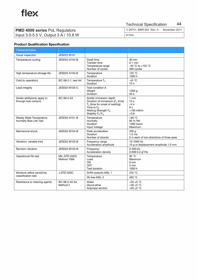
Ericsson Internal PRODUCT SPEC. MECHANICAL 4 (5)
Prepared (also subject responsible if other) No.
EPANHON 5/1301-BMR 652 Uen Approved Checked Date Rev Reference
SEC/D (LINDA ZHONG) See end 2006-06-19 A
Product Qualification Specification
Characteristics Visual inspection JESD22-B101
Temperature cycling JESD22-A104-B Dwell time Transfer time Temperature range Number of cycles
30 min 0-1 min-40 °C to +125 °C300 cycles
High temperature storage life JESD22-A103-B Temperature Duration
125 °C 1000 h
Cold (in operation) IEC 68-2-1, test Ad Temperature TA Duration
-45 °C72 h
Lead integrity JESD22-B105-C Test condition A Weight Duration
1000 g 30 s
Solder ability(only apply to through hole version)
IEC 68-2-54 Solder immersion depth Duration of immersion (FC time) TA (time for onset of wetting) Time to FB
Wetting Strength FB
Stability FC /FB
1 mm 15 s <4 s 8 s >100 mN/m>0.8
Steady State Temperature Humidity Bias Life Test
JESD22-A101-B Temperature Humidity Duration Input Voltage
+85 °C85 % RH1000 hoursMaximum
Mechanical shock JESD22-B104-B Peak acceleration Duration Number of shocks
200 g 1.5 ms 5 in each of two directions of three axes
Vibration, variable freq JESD22-B103-B Frequency range Acceleration amplitude
10-1000 Hz10 g or displacement amplitude 1.0 mm
Random vibration JESD22-B103-B Frequency Acceleration density
2-500 Hz0.008-0.2 g2/Hz
Operational life test MIL-STD-202G Method 108A
Temperature Load ON OFF Test duration
85 °C Maximum 9 min 3 min 1000 h
SnPb eutectic MSL 1 225 °C Moisture reflow sensitivity classification test
J-STD-020C
Pb free MSL 3 260 °C
Resistance to cleaning agents IEC 68-2-45 Xa Method 2
Water Glycol ether Isopropyl alcohol
+55 ±5 °C+35 ±5 °C+35 ±5 °C
E
PMD 4000 seriesPOL regulator, Input 3.0-5.5 V, Output 3 A/10.8 W
EN/LZT 146 350 R1B June 2006
© Ericsson Power Modules AB
Technical Specifi cation
E
PMD 4000 seriesPOL regulator, Input 3.0-5.5 V, Output 3 A/10.8 W
EN/LZT 146 350 R1C Aug 2006
© Ericsson Power Modules AB
Technical Specifi cation
E
PMD 4000 seriesPOL regulator, Input 3.0-5.5 V, Output 3 A/10.8 W
EN/LZT 146 350 R1D Dec 2006
© Ericsson Power Modules AB
Technical Specifi cation
E
PMD 4000 seriesPOL regulator, Input 3.0-5.5 V, Output 3 A/10.8 W
EN/LZT 146 350 R1E Jan 2009
© Ericsson Power Modules AB
Technical Specifi cation
PMD 4000 series PoL Regulators Input 3.0-5.5 V, Output 3 A / 10.8 W
1/ 28701- BMR 652 Rev. A November 2017
© Flex
Technical Specification 44