7h0011x0 w&c tech handbook sec 11
TRANSCRIPT

11. Industry Standards|
| 171
11. INDUSTRYSTANDARDS11.1 Industry Standards List
11.1.1 AAR 173
11.1.2 AEIC 174
11.1.3 ANSI 175
11.1.4 ASTM 176
11.1.5 Telcordia (formerly Bellcore) 179
11.1.6 CANENA 180
11.1.7 ECA 181
11.1.8 EIA 181
11.1.9 FAA 182
11.1.10 ICEA 182
11.1.11 IEC 184
11.1.12 IEEE 186
11.1.13 ISA 188
11.1.14 ISO 188
11.1.15 ITU-T 188
11.1.16 MSHA 188
11.1.17 NEMA 189
11.1.18 NFPA 190
11.1.19 RUS 190
11.1.20 SAE 191
11.1.21 TIA 192
11.1.22 UL 193
11.1.23 U.S. Government Specifications 195

11.2 Fire Safety Tests11.2.1 Fire Safety Test Methods 196
11.2.2 NEC Fire Test Summary 197
11.2.3 Comparison of Vertical Cable Tray Tests 198
11.2.4 NFPA 262 Steiner Tunnel Test for Plenum Rated Cable 199
11.2.5 UL 1666 Riser Flame Test 200
11.2.6 UL 1581 Vertical Tray Flame Test 200
11.2.7 ICEA T-29-520 201
11.2.8 CSA FT4 201
11.2.9 IEEE 1202 201
11.2.10 UL 1685 201
11.2.11 UL 1581 VW-1 Flame Test 202
11.3 Regulatory and Approval Agencies11.3.1 Underwriters Laboratories 203
11.3.2 National Electrical Code (NEC) 204
11.3.3 International 206
172 |
|11. Industry Standards

11. Industry Standards|
| 173
11.1 INDUSTRY STANDARDS LIST
11.1.1 AARAssociation of American Railroadswww.aar.org or www.arema.org
Document No. Title
581.3 Specification for Single Conductor, Clean Stripping Rubber Insulated, 0–600 Volt, Neoprene Jacketed Cable for Locomotive and Car Equipment
S-501 Wiring and Cable Specification
S-502 Specification for Single Conductor, Chlorosulfonated Polyethylene Integral Insulated-Jacketed, 0–300 Volt, 0–600 Volt Cable for Locomotive and Car Equipment
S-503 Specification for Single Conductor, Silicone Rubber Insulation, 0–300 Volt, 0–600 Volt, Glass Polyester Braided, 125°C Cable for High Temperature Use on Locomotive and Car Equipment
S-506 Specification for Single Conductor, Clean Stripping Ethylene Rubber Insulated, 0–600 Volt, Chlorosulfonated Polyethylene Jacketed Cable for Locomotive and Car Equipment
S-4210 ECP Brake System Cable
– Communications and Signals Manual, Section 10, Wire and Cable

174 |
|11. Industry Standards
11.1.2 AEICAssociation of Edison Illuminating Companieswww.aeic.org
Document No. Title
CG1 Guide for Application of AEIC Maximum Insulation Temperatures at the Conductor for Impregnated Paper-Insulated Cables
CG3 Installation of Pipe-Type Cable Systems
CG4 Installation of Extruded Dielectric Insulated Power Cable Systems Rated 69 kV through 138 kV
CG5 Underground Extruded Cable Pulling Guide
CG7 Guide for Replacement and Life Extension of Extruded Dielectric 5 through 35 kV Underground Distribution Cables
CG11 Reduced Diameter Extruded Dielectric Shielded Power Cables Rated 5 through 46 kV
CS1 Impregnated Paper-Insulated, Metallic-Sheathed Cable Solid Type
CS2 Impregnated Paper-Insulated Cable, High-Pressure Pipe Type
CS3 Impregnated Paper-Insulated, Metallic-Sheathed, Low Pressure, Gas-Filled
CS4 Impregnated Paper-Insulated Low and Medium-Pressure Self-Contained, Liquid-Filled Cable
CS7 Cross-Linked Polyethylene Insulated Shielded Power Cables, 69 through 138 kV
CS8 Extruded Dielectric Shielded Power Cables Rated 5 through 46 kV
CS9 Extruded Insulation Power Cables and Accessories Rated Above 46 kV through 345 kV
CS31 Electrically Insulating Low Viscosity Pipe Filling Liquids for High-Pressure Pipe-Type Cables

11. Industry Standards|
| 175
11.1.3 ANSIAmerican National Standards Institutewww.ansi.org
Document No. Title
0337-D Local Distributed Data Interface (LDDI) Network Layer Protocol
0338-D Data-Link Layer Protocol for Local Distributed Data Interfaces
0382-D Fiber Distributed Data Interface (FDDI) Network Layer Protocol
0503-D Fiber Distributed Data Interface (FDDI) Station Management Standard
0684-D FDDI—Media Access Control
719 Nonmetallic-Sheathed Cables
X3.129 Intelligent Peripheral Interface (IPI) Enhanced Physical Interface (withdrawn)
X3.148 Fiber Distributed Data Interface (FDDI) Physical Layer (replaced by document #INCITS 148)
X3.184 Fiber Distributed Data Interface (FDDI) Single-Mode Fiber Physical Layer Medium Dependent (replaced by document #INCITS 184)
176 |
|11. Industry Standards
11.1.4 ASTMAmerican Society for Testing and Materialwww.astm.org
Document No. Title
B1 Hard-Drawn Copper Wire
B2 Medium-Hard-Drawn Copper Wire
B3 Soft or Annealed Copper Wire
B8 Concentric-Lay-Stranded Copper Conductors, Hard, Medium-Hard, or Soft
B33 Tinned Soft or Annealed Copper Wire
B47 Copper Trolley Wire
B49 Hot-Rolled Copper Rods
B105 Hard-Drawn Copper Alloy Wires for Electrical Conductors
B172 Rope-Lay-Stranded Copper Conductors (Bunch Stranded Members)
B173 Rope-Lay-Stranded Copper Conductors (Concentric Stranded Members)
B174 Bunch-Stranded Copper Conductors
B189 Lead-Alloy-Coated Soft Copper Wire
B193 Resistivity of Electrical Conductor Materials
B227 Hard-Drawn Copper Clad Steel Wire
B228 Concentric-Lay-Stranded Copper-Clad Steel Conductors
B229 Concentric-Lay-Stranded Copper and Copper-Clad Steel Composite Conductors
B230 Aluminum 1350-H19 Wire, for Electrical Purposes
B231 Concentric-Lay-Stranded Aluminum 1350 Conductors
B232 Concentric-Lay-Stranded Aluminum Conductors, Coated-Steel Reinforced (ACSR)
B233 Aluminum 1350 Drawing Stock for Electrical Purposes
B246 Tinned Hard-Drawn and Medium-Hard-Drawn Copper Wire
B258 Standard Nominal Diameters and Cross-Sectional Areas of AWG Sizes of Solid Round Wire Used as Electrical Conductors
B263 Determination of Cross-Sectional Area of Stranded Conductors
B298 Silver-Coated Soft or Annealed Copper Wire
B324 Aluminum Rectangular and Square Wire
B399 Concentric-Lay-Stranded Aluminum Alloy 6201-T81 Conductors
B400 Compact Round Concentric-Lay-Stranded Aluminum 1350 Conductors
Continued on next page >>

11. Industry Standards|
| 177
11.1.4 ASTM (Continued)
Document No. Title
B401 Compact-Round Concentric-Lay-Stranded Aluminum Conductors, Steel Reinforced (ASCR/COMP)
B452 Copper-Clad Steel Wire for Electronic Application
B496 Compact Round Concentric-Lay-Stranded Copper Conductors
B500 Metallic Coated Stranded Steel Core for Aluminum Conductors, Steel Reinforced (ACSR)
B549 Concentric-Lay-Stranded Aluminum Conductors, Aluminum Clad Steel Reinforced (ACASR/AW)
B566 Copper-Clad Aluminum Wire
B609 Aluminum 1350 Round Wire, Annealed and Intermediate Tempers
B624 High Strength, High Conductivity, Copper Alloy Wire
B694 Copper, Copper Alloy, Copper-Clad Bronze, Copper-Clad Stainless Steel and Strip for Electrical Cable Shielding
B736 Aluminum; Aluminum Alloy, Aluminum Clad Steel Cable Shielding Stock
B800 8000 Series Aluminum Alloy Wire
B801 Concentric-Lay-Stranded Conductors of 8000 Series Aluminum Alloy
D470 Test Methods for Cross-Linked Insulations and Jackets for Wire and Cable
D866 Styrene-Butadiene (SBR) Synthetic Rubber Jacket for Wire and Cable
D1047 Polyvinyl Chloride Jacket for Wire and Cable
D1351 Polyethylene-Insulated Wire and Cable
D1523 Synthetic Rubber Insulation for Wire and Cable, 90°C Operation
D1929 Test for Ignition Temperature of Plastics
D2219 Polyvinyl Chloride Insulation for Wire and Cable, 60°C Operation
D2220 Polyvinyl Chloride Insulation for Wire and Cable, 75°C Operation
D2308 Polyethylene Jacket for Electrical Insulated Wire and Cable
D2655 Cross-linked Polyethylene Insulation for Wire and Cable Rated 0 to 2,000 V
D2656 Cross-linked Polyethylene Insulation for Wire and Cable Rated 2,001 V to 35 kV
D2671 Test Methods for Heat-Shrinkable Tubing
D2768 General-Purpose Ethylene-Propylene Rubber Jacket for Wire and Cable
D2770 Ozone-Resisting Ethylene Propylene Rubber Integral Insulation and Jacket for Wire
D2802 Ozone Resistant Ethylene-Alkene Polymer Insulation for Wire and Cable
D2863 Test Method for Measuring the Minimum Oxygen Concentration to Support Candle-Like Combustion of Plastics (Oxygen Index)
Continued on next page >>

178 |
|11. Industry Standards
11.1.4 ASTM (Continued)
Document No. Title
D3554 Track-Resistant Black Thermoplastic High Density Polyethylene Insulation for Wire and Cable
D3555 Track-Resistant Black Cross-linked Thermosetting Polyethylene Insulation for Wire and Cable
D4244 General Purpose, Heavy-Duty and Extra-Heavy-Duty NBR/PVC Jackets for Wire and Cable
D4245 Ozone-Resistant Thermoplastic Elastomer Insulation for Wire and Cable, 90°C Dry–75°C Wet Operation
D4246 Ozone-Resistant Thermoplastic Elastomer Insulation for Wire and Cable, 90°C Operation
D4314 Specification for General Purpose, Heavy-Duty and Extra-Heavy-Duty Cross-linked Chlorosulfonated Polyethylene Jackets for Wire and Cable
D4565 Test Methods for Physical and Environmental Performance Properties of Insulations and Jackets for Telecommunications Wire and Cable
D4566 Test Methods for Electrical Performance Properties of Insulations and Jackets for Telecommunications Wire and Cable
D5537 Heat Release, Flame Spread and Mass Loss Testing of Insulating Materials Contained in Electrical or Optical Fiber Cables WhenBurning in a Vertical Cable Tray Configuration
E574 Duplex, Base Metal Thermocouple Wire with Glass Fiber or Silica Fiber Insulation
E662 Specific Optical Density of Smoke Generated by Solid Materials
E1354 Heat and Visible Smoke Release Rates for Materials and Products Using an Oxygen Consumption Calorimeter

11. Industry Standards|
| 179
11.1.5 Telcordia (formerly Bellcore)www.telcordia.com
Document No. Title
GR-20 Generic Requirements for Optical Fiber and Optical Fiber Cable
GR-63 Network Equipment-Building System Requirements: Physical Protection
GR-78 Generic Physical Design Requirements for Telecommunication Products and Equipment
GR-110 Generic Requirements for Thermoplastic Insulated Steam Resistant Cable
GR-111 Generic Requirements for Thermoplastic Insulated Riser Cable
GR-115 Inner-City PIC Screened Cable (Filled, AASP Bonded, STALPETH and Bonded PASP)
GR-126 Generic Requirements for Network Outdoor Customer Premises and Universal Cross-Connecting Wire
GR-135 Generic Requirements for Miniature Ribbon Connector and Cable Assembly
GR-136 Generic Requirements for Distributing Frame Wire
GR-137 Generic Requirements for Central Office Cable
GR-139 Generic Requirements for Central Office Coaxial Cable
GR-326 Generic Requirements for Singlemode Optical Connectors and Jumpers
GR-347 Generic Requirements for Telecommunications Power Cable
GR-356 Generic Requirements for Optical Cable Innerduct
GR-409 Generic Requirements for Premises Optical Fiber Cable
GR-421 Generic Requirements for Metallic Telecommunications Cable
GR-492 Generic Requirements for Metallic Telecommunication Wire
GR-1398 Generic Requirements for Coaxial Drop Cable
GR-1399 Generic Requirements for Coaxial Distribution Cable
TR-NWT-000123 Single Pair Buried Distribution Wire
TR-NWT-000124 Multiple Pair Buried Wire
TR-NWT-000131 Generic Requirements for Network Plenum Cable/Wire
TR-NWT-000132 Generic Requirements for Network Shielded Station Wire
TR-NWT-000133 Generic Requirements for Inside Wiring Cable (3 to 125 Pair Sizes)
TR-NWT-000134 Generic Requirements for Two Pair Station Wire
TR-TSY-000103 Pulp Bonded STALPETH Cable
TR-TSY-000104 Pulp Bonded PASP Cable
Continued on next page >>
180 |
|11. Industry Standards
11.1.5 Telcordia (Continued)
Document No. Title
TR-TSY-000105 Pulp Bonded Steam Resistance Cable
TA-TSY-000120 Customer Premises or Network Ground Wire
TA-TSY-000121 Generic Requirements for One-Pair Aerial Service Wire
TA-TSY-000122 Generic Requirements for Multiple-Pair Aerial Service Wire
TA-TSY-000125 Rural Aerial Distribution Wire
TA-TSY-000127 Network Aerial Block Wire
TA-TSY-000128 Bridle Wire
TA-TSY-000129 Tree Wire
TA-TSY-000140 Standard Shielded Polyethylene Insulated Twisted Pair Cable
TA-TSY-000141 Terminating Cable
TA-TSY-000142 Central Office Hook-up Wire
11.1.6 CANENACouncil for the Harmonization of Electrical Standards of the Americaswww.canena.org
THC (Technical Harmonization Committee) #20 is responsible for wire and cable products.

11. Industry Standards|
| 181
11.1.7 ECAElectronic Components, Assemblies and Materials Associationwww.ec-central.org
Document No. Title
ECA-199-A Solid and Semisolid Dielectric Transmission Lines
ECA-215 Broadcast Microphone Cables
ECA-230 Color Marking of Thermoplastic Covered Wire
ECA-280-C Solderless Wrapped Electrical Connections
ECA-297-A Cable Connectors for Audio Facilities for Radio Broadcasting
ECA-364 Electrical Connector Test Procedures
ECA-403-A Precision Coaxial Connectors for CATV 75 Ohms
ECA-IS-43 Omnibus Specification–Local Area Network Twisted Pair Data Communication Cable
ECA-IS-43AA Cable for LAN Twisted Pair Data Communications–Detail Specification for Type 1, Outdoor Cable
ECA-IS-43AB Cable for LAN Twisted Pair Data Communications–Detail Specification for Type 1, Non-Plenum Cable
ECA-IS-43AC Cable for LAN Twisted Pair Data Communications–Detail Specification for Type 1, Riser Cable
ECA-IS-43AD Cable for LAN Twisted Pair Data Communications–Detail Specification for Type 1, Plenum Cable
ECA-IS-43AE Cable for LAN Twisted Pair Data Communications–Detail Specification for Type 2, Non-Plenum Cable
ECA-IS-43AF Cable for LAN Twisted Pair Data Communications–Detail Specification for Type 2, Plenum Cable
ECA-IS-43AG Cable for LAN Twisted Pair Data Communications–Detail Specification for Type 6, Office Cable
ECA-IS-43AH Cable for LAN Twisted Pair Data Communications–Detail Specification for Type 8, Undercarpet Cable
ECA-IS-43AJ Cable for LAN Twisted Pair Data Communications–Detail Specification for Type 9, Plenum Cable
11.1.8 EIAElectronic Industries Alliancewww.eia.org
EIA documents are available from Global Engineering Documents, Inc. www.global.ihs.com
Document No. Title
EIA-492A000 Specification for Multimode Optical Wave Guide Fibers
EIA-359-A Standard Colors for Color Identification and Coding (Munsell Color)

182 |
|11. Industry Standards
11.1.9 FAAFederal Aviation Administrationwww.faa.gov
Document No. Title
AC 25.869-1 Fire and Smoke Protection
AC 150/534-7 Underground Electrical Cables for Airport Lighting Circuits (L-824-A, B, C)
AC-150/5345-53 Airport Lighting Certification Program
AC-150/5370-10 Airport Construction Standards
FAA-E-2042 Control Cable, Exterior
FAA-E-2793 Power Cable, Exterior, 5 to 25 kV
FAA-701 Rubber-Insulated Cable (0–8,000 Volts)
FAR 14, 25.869 (a)(4) Fire Retardance of Wire and Cable
11.1.10 ICEAInsulated Cable Engineers Associationwww.icea.net
ICEA documents are available from Global Engineering Documents, Inc. www.global.ihs.com
Document No. Title
S-56-434 Polyolefin Insulated Communication Cables for Outdoor Use
S-61-402 Thermoplastic-Insulated Wire and Cable for the Transmission and Distribution of Electrical Energy (NEMA WC 5)
S-81-570 600 V Direct Burial Cable Single Electrical Conductors and Assemblies with Ruggedized Extruded Insulation
P-32-382 Short Circuit Characteristics of Insulated Cable
P-43-457 Conductor Resistances and Ampacities at 400 and 800 Hz
P-45-482 Short Circuit Performance of Metallic Shields and Sheaths on Insulated Cable
P-46-426 Power Cable Ampacities (Replaced by IEEE 835)
P-51-432 Copper Conductors, Bare and Weather Resistant
P-53-426 Ampacities, Including Effect of Shield Losses for Single-Conductor Solid-Dielectric Power Cable 15 kV Through 69 kV (NEMA WC 50)
P-54-440 Ampacities of Cables in Open-Top Cable Trays (NEMA WC 51)
P-56-520 Cable Tray Flame Test
S-65-375 Varnished-Cloth-Insulated Wire and Cable for the Transmission and Distribution of Electrical Energy (NEMA WC 4)
S-70-547 Weather-Resistant Polyethylene Covered Conductors
Continued on next page >>

11. Industry Standards|
| 183
11.1.10 ICEA (Continued)
Document No. Title
S-73-532 Standard for Control Cables (NEMA WC 57)
S-75-381 Portable and Power Feeder Cables for Use in Mines and Similar Applications (NEMA WC 58)
S-80-576 Category 1 and 2 Unshielded Twisted Pair Communications Cable for Wiring Premises
S-82-552 Instrumentation Cables and Thermocouple Wire (NEMA WC 55)
S-83-596 Optical Fiber Premises Distribution Cable
S-87-640 Fiber Optic Outside Plant Communications Cable
S-94-649 Concentric Neutral Cables Rated 5 through 46 kV
S-97-682 Utility Shielded Power Cables Rated 5 through 46 kV
S-104-696 Indoor-Outdoor Optical Fiber Cable
S-110-717 Optical Fiber Drop Cable
T-22-294 Test Procedures for Extended Time-Testing of Insulation for Service in Wet Locations
T-25-425 Guide for Establishing Stability of Volume Resistivity for Conducting Polymeric Components of Power Cables
T-26-465 Guide for Frequency of Sampling Extruded Dielectric Power, Control, Instrumentation and Portable Cables for Test (NEMA WC 54)
T-27-581 Standard Test Methods for Extruded Dielectric Power, Control, Instrumentation and Portable Cables (NEMA WC 53)
T-29-520 Conducting Vertical Cable Tray Flame Tests (210,000 BTU/Hour)
T-30-520 Conducting Vertical Cable Tray Flame Tests (70,000 BTU/Hour)
T-31-610 Water Penetration Resistance Test, Sealed Conductor
T-33-655 Low-Smoke, Halogen-Free (LSHF) Polymeric Cable Jackets
184 |
|11. Industry Standards
11.1.11 IECInternational Electrotechnical Commissionwebstore.iec.ch
Document No. Title
24764 Information Technology–Generic Cabling for Data Center Premises (not yet published)
60050-461 International Electrotechnical Vocabulary. Chapter 461. Electric cables.
60055-2 Paper-insulated metal-sheathed cables for rated voltages up to 18/30 kV (with copper or aluminum conductors and excluding gas pressure and oil-filled cables)
60079 Electrical apparatus for explosive atmospheres (hazardous locations)
60092 Electrical installations in ships
60096 Radio-frequency cables
60141 Tests on oil-filled and gas-pressure cables and their accessories
60169 Radio-frequency connectors
60173 Colors of the cores of flexible cables and cords
60183 Guide to selection of high-voltage cables
60189 Low-frequency cables and wires with PVC insulation and PVC sheath
60204 Safety of machinery–electrical equipment of machines (industrial)
60227 PVC insulated cables of rated voltages up to and including 450/750 V
60228 Conductors of insulated cables
60229 Tests on cable oversheaths which have a special protective function and are applied by extrusion
60230 Impulse tests on cables and their accessories
60245 Rubber insulated cables of rated voltages up to and including 450/750 V
60287 Calculations of the continuous current rating of cables (100% load factor)
60304 Standard colors for insulation for low-frequency cables and wires
60331 Tests for electric cables under fire conditions–circuit integrity
60332 Tests on electric and optical fiber cables under fire conditions
60339 General purpose rigid coaxial transmission lines and their associated flange connectors
TR60344 Calculation of DC resistance of plain and coated copper conductors of low-frequency cables and wires
60364-1 Low-voltage electrical installations–Part 1: Fundamental principles, assessment of global characteristics, definitions
60446 Identification of conductors by colors or alphanumeric
60457 Rigid precision coaxial lines and their associated precision connectors
Continued on next page >>

11. Industry Standards|
| 185
11.1.11 IEC (Continued)
Document No. Title
60502 Extruded solid dielectric insulated power cables for rated voltages from 1 kV to 30 kV
60541 Comparative information on IEC and North American flexible cord types
TR60649 Calculation of maximum external diameter of cables for indoor installations
60695 Fire hazard testing
60702 Mineral insulated cables with a rated voltage not exceeding 750 V
60708 Low-frequency cables with polyolefin insulation and moisture barrier polyolefin sheath
60719 Calculation of the lower and upper limits for the average outer dimensions of cables with circular copper conductors and of rated voltages up to and including 450/750 V
60724 Short-circuit temperature limits of electric cables with rated voltages 1 kV and 3 kV
60728 Cable networks for sound and television signals
60754 Tests on gases evolved during combustion of electric cables
60757 Code for designation of colors
60800 Heating cables with a rated voltage of 300/500 V for comfort heating and prevention of ice formation
60811 Common tests methods for insulating and sheathing materials of electric and optical cables
60834 Performance and testing of teleprotection equipment of power systems
60840 Tests for power cables with extruded insulation for rated voltages above 30 kV up to 150 kV
60851 Winding wires–test methods
60885 Electrical test methods for electric cables (including partial discharge)
60949 Calculation of thermally permissible short-circuit currents
60966 Radio-frequency and coaxial cable assemblies
61034 Measurement of smoke density of cables burning under defined conditions (3 meter cube smoke apparatus)
61158 Fieldbus for use in industrial control systems
61883 Consumer audio/video equipment–Digital interface
61936-1 Power installations exceeding 1 kV AC Part 1: Common rules

186 |
|11. Industry Standards
11.1.12 IEEEInstitute of Electrical and Electronic Engineers, Inc.www.ieee.org
Document No. Title
45 Recommended Practice for Electrical Installations on Shipboard
48 Test Procedures and Requirements for AC Cable Terminations 2.5 kV through 765 kV
82 Test Procedure for Impulse Voltage Tests on Insulated Conductors
101 Guide for the Statistical Analysis of Thermal Life Test Data
120 Master Test Guide for Electrical Measurements in Power Circuits
323 Qualifying Class 1E Equipment for Nuclear Power Generating Stations
383 Qualifying Class 1E Electric Cables, Field Splices and Connections for Nuclear Power Generating Stations
400 Guide for Field Testing and Evaluation of the Insulation of Shielded Power Cable Systems
404 Standard for Extruded and Laminated Dielectric Shielded Cable Joints Rated 2.5 kV through 500 kV
422 Guide for Design and Installation of Cable Systems in Power Generating Stations (withdrawn)
510 Recommended Practices for Safety in High Voltage and High Power Testing
524 Guide to the Installation of Overhead Transmission Line Conductors
525 Guide for the Design and Installation of Cable Systems in Substations
532 Guide for Selecting and Testing Jackets for Underground Cables
539 Definitions of Terms Relating to Corona and Field Effects of Overhead Powerlines
575 Guide for the Application of Sheath-Bonding Methods for Single Conductor Cables and the Calculation of Induced Voltages and Currents in Cable Sheaths
576 Recommended Practice for Installation, Termination, and Testing of Insulated Power Cable as Used in Industrial and Commercial Applications
634 Standard Cable Penetration Fire Stop Qualification Test
635 Guide for Selection and Design of Aluminum Sheaths for Power Cables
690 Standard for the Design and Installation of Cable Systems for Class 1E Circuits in Nuclear Power Generating Stations
738 Standard for Calculating the Current-Temperature of Bare Overhead Conductors
802 Local and Metropolitan Area Networks: Overview and Architecture
816 Guide for Determining the Smoke Generation of Solid Materials Used for Insulations and Coverings of Electrical Wire and Cable (withdrawn)
835 Power Cable Ampacity Tables
848 Standard Procedure for the Determination of the Ampacity Derating of Fire-Protected Cables
Continued on next page >>

11. Industry Standards|
| 187
11.1.12 IEEE (Continued)
Document No. Title
930 Statistical Analysis of Electrical Insulation Breakdown Data
1017 Field Testing Electric Submersible Pump Cable
1018 Specifying Electric Submersible Cable-Ethylene-Propylene Rubber Insulation
1019 Specifying Electric Submersible Pump Cable-Polypropylene Insulation
1143 Guide on Shielding Practice for Low Voltage Cables
1185 Guide for Installation Methods for Generating Station Cables
1202 Standard for Propagation Flame Testing of Wire and Cable
1394 Standard for a High Performance Serial Bus
1407 Guide for Accelerated Aging Test for MV Power Cables Using Water-Filled Tanks
C2 National Electrical Safety Code (NESC)
C62.41 Surge Voltages in Low-Voltage (1,000 V and less) AC Power Circuits
C62.92 Neutral Grounding in Electrical Utility Systems

188 |
|11. Industry Standards
11.1.13 ISAInstrumentation, Systems and Automation Societywww.isa.org
Document No. Title
RP 12.06.01 Wiring Methods for Hazardous (Classified) Locations Instrumentation Part 1: Intrinsic Safety
50.02 Fieldbus Standard for Use in Industrial Control Systems
11.1.14 ISOInternational Organization for Standardizationwww.iso.org
Document No. Title
4589 Oxygen Index Test
5657 Radiant Cone Flame Test
TR9122 Toxicity Testing of Fire Effluents
11.1.15 ITU-TInternational Telecommunication Union/Telecommunications Sectorwww.itu.int
Document No. Title
Blue Book, Facicle III.3 Transmission Media Characteristics
11.1.16 MSHAMine Safety and Health Administrationwww.msha.gov
Document No. Title
30 CFR 7.407 Flame Tests

11. Industry Standards|
| 189
11.1.17 NEMANational Electrical Manufacturers Associationwww.nema.org
Document No. Title
HP 3 Electrical and Electronic PTFE Insulated High Temperature Hook-up Wire; Types ET (250 Volts), E (600 Volts) and EE (1,000 Volts)
HP 4 Electrical and Electronic FEP Insulated High Temperature Hook-up Wire: Types KT (250 Volts), K (600 Volts) and KK (1,000 Volts)
HP 100 High Temperature Instrumentation and Control Cable
HP 100.1 High Temperature Instrumentation and Control Cables Insulated and Jacketed with FEP Fluorocarbons
HP 100.2 High Temperature Instrumentation and Control Cables Insulated and Jacketed with ETFE Fluoropolymers
HP 100.3 High Temperature Instrumentation and Control Cables Insulated and Jacketed with Cross-Linked (Thermoset) Polyolefin (XLPO)
HP 100.4 High Temperature Instrumentation and Control Cables Insulated and Jacketed with ECTFE Fluoropolymers
WC 26 Wire and Cable Packaging
WC 50 Ampacities, Including Effect of Shield Losses for Single-Conductor Solid-Dielectric Power Cable 15 kV through 69 kV (ICEA P-53-426)
WC 51 Ampacities of Cables Installed in Cable Trays
WC 52 High-Temperature and Electronic Insulated Wire Impulse Dielectric Testing
WC 53 Standard Test Methods for Extruded Dielectric Power, Control, Instrumentation and Portable Cables (ICEA T-27-581)
WC 54 Guide for Frequency of Sampling Extruded Dielectric Power, Control, Instrumentation and Portable Cables for Test
WC 56 3.0 kHz Insulation Continuity Proof Testing of Hookup Wire
WC 57 Standard for Control Cables (ICEA S-73-532)
WC 58 Portable and Power Feeder Cables for Use in Mines and Similar Applications (ICEA S-75-381)
WC 61 Transfer Impedance Testing
WC 62 Repeated Spark/Impulse Dielectric Testing
WC 63.1 Twisted Pair Premise Voice and Data Communications Cables
WC 63.2 Coaxial Premise Data Communication Cable
WC 66 Category 6 and Category 7 100 Ohm Shielded and Unshielded Twisted Pair Cables
WC 67 Uninsulated Conductors
WC 70 Nonshielded Power Cables Rated 2,000 Volts or Less
WC 71 Nonshielded Cables Rated 2,001–5,000 Volts
WC 27500 Aerospace and Industrial Electrical Cable

190 |
|11. Industry Standards
11.1.18 NFPANational Fire Protection Associationwww.nfpa.org
Document No. Title
70 NEC® (National Electrical Code)
75 Protection of Electronic Computer/Data Processing Equipment
79 Electrical Standard for Industrial Machinery
99 Health Care Facilities Handbook
258 Recommended Practice for Determining Smoke Generation of Solid Materials
262 Test for Flame Travel and Smoke of Wires and Cables for Use in Air-Handling Spaces
11.1.19 RUSRural Utilities Service (formerly REA)www.usda.gov/rus/telecom
Document No. Title
1753F-150 Construction of Direct Buried Plant
1753F-151 Construction of Underground Plant
1753F-152 Construction of Aerial Plant
1753F-204 Aerial Service Wires (PE-7)
1753F-205 Filled Telephone Cable (PE-39)
1753F-206 Filled Buried Wires (PE-86)
1753F-208 Filled Telephone Cable with Expanded Insulation (PE-89)
1753F-601 Filled Fiber Optic Cables (PE-90)

11. Industry Standards|
| 191
11.1.20 SAE International (formerly Society of Automotive Engineers)www.sae.org
Document No. Title
J156 Fusible Links
J378 Marine Engine Wiring
J1127 Low Voltage Battery Cable
J1128 Low Voltage Primary Cable
J1292 Automobile Truck, Truck-Tractor, Trailer, and Motor Coach Wiring
J1654 High Voltage Primary Cable
J1678 Low Voltage Ultra Thin Wall Primary Cable
J1939 Serial Control and Communications for Vehicle Network
J2394 Seven-Conductor Cable for ABS Power
AS22759 Fluoropolymer Insulated Electrical Wire
AS50861 PVC Insulated, Copper or Copper Alloy Wire
AS50881 Wiring Aerospace Vehicle
AS81044 Wire, Electric, Cross-linked Polyalkene, Cross-linked Alkane-Imide Polymer, or Polyarylene Insulated, Copper or Copper Alloy

192 |
|11. Industry Standards
11.1.21 TIATelecommunication Industries Associationwww.tiaonline.org
Document No. Title
TIA-225 Rigid Coaxial Transmission Lines 50 Ohms
TIA-232-F Interface Between Data Terminal Equipment and Data Communication Equipment Employing Serial Binary Data Interchange
TIA-259 Rigid Coaxial Transmission Lines and Connectors, 75 Ohms
TIA-422-B Electrical Characteristics of Balanced Voltage Digital Interface Circuits
TIA/EIA-423-B Electrical Characteristics of Unbalanced Voltage Digital Interface Circuits
TIA-440-B Fiber Optic Terminology
TIA-485-A Generators and Receivers for Balanced Digital Multipoint Systems
TIA/EIA-455-B Standard Test Procedures for Fiber Optic Fibers, Cables, Transducers, Connecting and Termination
TIA-492AAAA-A Detail Specification for 62.5 µm Core Diameter/125 µm Cladding Diameter Class 1a Multimode, Graded-Index Optical Waveguide Fibers
TIA/EIA-568-B.1 Commercial Building Telecommunications Cabling Standard
TIA-569-B Commercial Building Standard for Telecommunications Pathways and Spaces
TIA-570-B Residential Telecommunications Infrastructure Standard
TIA/EIA-606-A Administration Standard for the Telecommunications Infrastructure
TIA-942 Telecommunications Infrastructure Standard for Data Centers
TIA-472C000 Sectional Specification for Fiber Optic Premises Distribution Cables
TIA-472D000 Sectional Specification for Fiber Optic Cables for Outside Plant Use
TIA-475C000 Specification for Fiber Optic Type FSMA Connectors
TIA-515B000 Specification for Optical Fiber Cable Splice Closures

11. Industry Standards|
| 193
11.1.22 ULUnderwriters Laboratories, Inc.www.ul.com
Document No. Title
4 Armored Cable (Type AC)
13 Power-Limited Circuit Cable (Types CL3P, CL2P, CL3R, CL2R, CL3, CL3X, PLTC)
44 Thermoset-Insulated Wires & Cables (Types XHHW, XHHW-2, RHH, RHW, RHW-2, RH, SA, SIS)
62 Flexible Cord & Fixture Wire (Types SO, SOW, SOW-A, SJ, SJO, SPT-1, TFN, TFFN, etc.)
66 Fixture Wire
83 Thermoplastic-Insulated Wires and Cables (Types TW, THW, THW-2, THWN, THWN-2, THHN, THHW, TA, TBS, TFE, FEP, FEPB)
183 Manufactured Wiring Systems
444 Communication Cables (Types CMX, CM, CMR, CMP)
486A-486B Wire Connectors
486C Splicing Wire Connectors
486D Sealed Wire Connector Systems
486E Equipment Wiring Terminals for Use with Aluminum and/or Copper Conductors
493 Thermoplastic Insulated Underground Feeder & Branch Circuit Cables (Types UF, UF-B)
497 Protectors for Communication Circuits
719 Nonmetallic-Sheath Cables (Types NM-B, NMC-B)
723 Tests for Surface Burning Characteristics of Building Materials
758 Appliance Wiring Material (Type AWM)
814 Gas-Tube-Sign Cable
817 Cord Sets and Power-Supply Cords
854 Service Entrance Cables (Types USE, SE, SE-U, SE-R, USE-2)
1063 Machine Tool Wires and Cables (Type MTW)
1072 Medium Voltage Power Cable (Type MV)
1276 Welding Cables
1277 Power and Control Tray Cables (Type TC)
1309 Marine Shipboard Cable
1424 Cables for Power-Limited Fire-Alarm Circuits
1425 Cables for Non-Power-Limited Fire-Alarm Circuits
Continued on next page >>

194 |
|11. Industry Standards
11.1.22 UL (Continued)
Document No. Title
1426 Electric Cables for Boats
1459 Telephone Equipment
1565 Positioning Devices
1581 Reference Standard for Electrical Wires, Cables, and Flexible Cords
1604 Electrical Equipment for Use in Class I and II, Division 2, and Class III Hazardous (Classified) Locations
1650 Portable Power Cable (Types G, G-GC, W, PPE)
1651 Optical Fiber Cable
1666 Standard Test for Flame Propagation Height of Electrical and Optical Fiber Cables Installed Vertically in Shafts
1680 Stage Lighting Cables
1685 Vertical-Tray Fire-Propagation and Smoke-Release Test for Electrical and Optical-Fiber Cables
1690 Data-Processing Cable (Type DP)
1740 Industrial Robots
1863 Communication Circuit Accessories
2196 Fire Resistive Cables (“CI” Rated)
2225 Cables for Use in Hazardous Locations (Type MC-HL)
2250 Instrumentation Tray Cable (Type ITC)
2556 Wire and Cable Test Methods (Trinational)
2261 Cables for Network-Powered Broadband Systems
2273 Festoon Cable
2276 Recreational Vehicle Cable
2424 Limited-Combustible Cable
60079 Electrical Apparatus for Explosive Gas Atmospheres

11. Industry Standards|
| 195
11.1.23 U.S. Government Specificationshttp://assist.daps.dla.mil/quicksearch
Document No. Title
AA-59544 Wire & Cable Electrical Power
A-A-59551 Electrical Copper Wire, Uninsulated
J-C-145C Weather-Resistant Power & Cable
J-C-580B Flexible Cord and Fixture Wire (Replaced by UL 62)
MIL-DTL-17H General Specifications for Cables, Radio Frequency, Flexible and Semirigid
MIL-DTL-915G General Specification for Cable and Cord, Electrical, for Shipboard Use
MIL-DTL-3432H Cable (Power & Special Purpose) and Wire, Electrical (300–600 Volts)
MIL-DTL-8777D Wire, Electrical, Silicone-Insulated, Copper, 600 V, 200°C
MIL-DTL-13777H General Specifications for Cable, Special Purpose, Electrical
MIL-DTL-16878G General Specifications for Wire, Electrical, Insulated
MIL-DTL-23806B General Specification for Cable, Radio Frequency, Coaxial, Semirigid, Foam Dielectric
MIL-DTL-24640G General Specification for Cable, Electrical, Lightweight for Shipboard Use
MIL-DTL-24643B General Specification for Cable and Cord, Electrical, Low Smoke, for Shipboard Use
MIL-DTL-25038H Wire, Electrical, High Temperature, Fire Resistant and Flight Critical
MIL-DTL-27072F Special Purpose, Electrical, Multiconductor and Single Shielded Power Cable
MIL-DTL-28830D General Specification for Cable, Radio Frequency, Coaxial, Semirigid, Corrugated Outer Conductor
MIL-DTL-38359C Cable, Power, Electrical, Airport Lighting, Cross-Linked, Polyethylene XLP
MIL-DTL-49055D General Specifications for Cables, Power, Electrical (Flexible, Flat, Unshielded), Round Conductor
MIL-DTL-55021C General Specification for Cables Twisted Pairs and Triples, Internal Hookup
MIL-DTL-81381C Wire-Electric, Polymide-Insulated Copper or Copper Alloy
MIL-C-83522D General Specification for Connectors, Fiber Optic, Single Terminus
MIL-DTL-83526C General Specifications for Connectors, Fiber Optic, Circular, Environmental Resistant, Hermaphroditic
MIL-HDBK-299 Cable Comparison Handbook Data Pertaining to Electric Shipboard Cable
MIL-S-81824 Splices, Electric, Crimp Style, Copper, Insulated, Environment Resistant
MIL-W-76D Wire and Cable, Hookup, Electrical, Insulated
MIL-W-5846C Wire, Electrical, Chromel and Alumel Thermocouple
QPL-AS5756-I Cable and Wire, Power, Electric, Portable

196 |
|11. Industry Standards
11.2 FIRE SAFETY TESTS
11.2.1 Fire Safety Test Methods
Table 11.1–Fire Safety Test Methods
Some common fire safety test methods used in the wire and cable industry are listed below:
Fire Hazard North America Worldwide
Ignitability ASTM D2863 IEC 60332
Propagation UL 1685 and IEEE 1202 IEC 60332
Smoke UL 1685 and ASTM E662 IEC 61034-2
Toxicity University of Pittsburgh ISO TR 9122
Corrosivity IEC 60754 IEC 60754-2
Halogen Content MIL-DTL-24643 IEC 60754-1

11. Industry Standards|
| 197
11.2.2 NEC Fire Test Summary
Table 11.2–NEC Fire Test Summary
General Use Limited Use(UL 1581 (UL 1581
National Electrical Plenum Riser Vertical VerticalCode Article (NPFA 262) (UL 1666) Tray) Wire)
645 Under Raised All types All types DP, MC, AC –Floor of IT Room shown below shown below
725, Class 2 Power-Limited CL2P CL2R CL2 CL2X
725, Class 3 Power-Limited CL3P CL3R CL3 CL3X
725 Power-Limited No No PLTC NoTray Cable listing listing listing
727 Instrumentation No No ITC NoTray Cable listing listing listing
760 Fire Protective FPLP FPLR FPL NoPower-Limited listing
760 Fire Protective NPLFP NPLFR NPLF NoNon-Power-Limited listing
770 Optical Fiber OFNP OFNR OFN or OFNG NoNonconductive listing
770 Optical Fiber OFCP OFCR OFC or OFCG NoConductive listing
800 Communication CMP CMR CM or CMG CMX
800 Undercarpet No No No CMUCCommunication listing listing listing
820 Cable TV CATVP CATVR CATV CATVX
Cable Application Common Names Flame Energy
Plenum Space NFPA 262, Steiner Tunnel, CSA FT6 300,000 Btu/hrRiser Shaft UL 1666, Riser Test 527,000 Btu/hrGeneral Use UL 1581 Vertical Tray, IEEE 1202, CSA FT4, UL 1685 70,000 Btu/hrLimited Use UL 1581 Vertical Wire, VW-1, CSA FT1 3,000 Btu/hr

198 |
|11. Industry Standards
11.2.3 Comparison of Vertical Cable Tray Tests
Table 11.3–Comparison of Vertical Cable Tray Tests
IEEE 383 ICEA CSA IEEE 1202 UL 1685 UL 1685 IECUL 1581 T-29-520 FT4 /ULa /IEEEb 60332-3
Burner power (kW) 21 62 20 20 21 21 20
Time of flame (min) 20 20 20 20 20 20 20, 40g
Alternate source Yes, oily ragd No No No No No No
Burner placementc 600 mme 300 mm 300 mm 300 mm 457 mm 457 mm 600 mm75 mm 200 mm 75 mm 75 mm 75 mm 75 mm 75 mmin back in back in front in front in back in front in front
Angle of burner Horiz. Horiz. 20° up 20° up Horiz. 20° up Horiz.
Tray length (m) 2.4 2.4 3.0 2.4 2.4 2.4 3.5
Tray width (m) 0.3 0.3 0.3 0.3 0.3 0.3 0.5
Sample length (m) 2.4 2.4 2.3 2.3 2.4 2.4 3.5
Width of tray used 0.15 0.15 0.25 Full 0.15 Full 0.30 frontfor cables (m) Front only Front only Front only Front only Front only or front
1 back
Thin-size cables to No No if D, if D, No if D, Mountedbe bundled 13 mm 13 mm 13 mm flush, with
no spaces
Test enclosure specified No No Yes Yes Yes Yes Yes
Required air flow rate N/A N/A . 0.17 m3/s 0.65 m3/s 5 m3/s 5m3/s h
Test runs needed 3 2 2 2 3 2f 1 1 1
Max. char length 2.4 2.4 1.786 1.786 2.4 1.786 3.1(m, from bottom)
Peak smoke release N/A N/A N/A N/A 0.25 0.40 N/Arate (m2 s-1)
Total smoke N/A N/A N/A N/A 95 150 N/Areleased (m2)
a=Version with UL 1581 flame exposure; b=Version with CSA FT-4/IEEE 1202 flame exposure; c=Height above bottom of tray and distance from specimensurface, respectively; d=Not applicable in the UL 1581 version; e=This dimension is 457 mm in the UL 1581 version; f=Two each on two different sizes of specimens; g=Time is 20 minutes for Category C, 40 minutes for Categories A and B; h=Not yet specified; i=Depends on amount of cable loading
Source: NIST Technical Note 1291

11. Industry Standards|
| 199
11.2.4 NFPA 262 Steiner Tunnel Test for Plenum Rated CableThe NFPA 262 “Steiner Tunnel” Flame Test (formerly UL 910) measures flame spread and smoke generation in a simulated air handling plenum. A 25-foot longSteiner Tunnel is used for the test, with intake and exhaust ducts and a means of regulating flow velocity of air through the tunnel. Windows at 1-foot intervalsallow for flame spread measurements, and an optical device in the exhaust of the chamber measures smoke density. The cable samples are mounted in acable tray in one layer in the tunnel and the tunnel is sealed. Two circular burners are mounted vertically at the intake end of the tunnel just in front of thecable tray. Methane is burned, along with a 240 ft./min forced draft through the tunnel for twenty minutes, and the flame is extinguished. Flame spread andsmoke density are monitored throughout the test. A cable is listed for plenum use if flame spread is less than 5 feet from the end of the ignition flame, and optical density is less than 0.5 maximum peak, and 0.15 maximum average. The output of the burner is 300,000 Btu/hr and the energy consumed for the test is 100,000 Btus. The Canadian version of this test is known as the CSA FT6 fire test.
Figure 11.1–NFPA Steiner Tunnel Flame Test
Air FlowPhotocell
Burners
Cables
25́ (7.62 m)

200 |
|11. Industry Standards
11.2.5 UL 1666 Riser Flame TestThe Riser Flame Test, as described in Underwriters Laboratories Standard 1666, was developed to test cable flammability in riser applications. This test simulates a fire in a nonflame stopped riser within a high-rise building. The chamber for the test is a three story block construction design. Steel fire doors provide access to the second and third levels for installing cables, and 1-foot 3 2-foot rectangular holes in both the second and third level floors allow cableto be installed in racks extending between the first and third levels. A burner is made up of a 1 ⁄4 in. gas pipe with 90 degree elbow mounted below a 1-footsquare drilled steel plate. The burner is mounted on the edge of the riser hole on the floor of the second level. A mixture of air and propane is burned for thirty minutes and then shut off, extinguishing the burner flame. A cable may be listed as riser cable if the flame does not propagate up to the floor of thethird level. The energy output of the burner is 527,500 Btu/hr, or a consumed test energy of 263,750 Btus.
Figure 11.2–UL 1666 Riser Flame Test
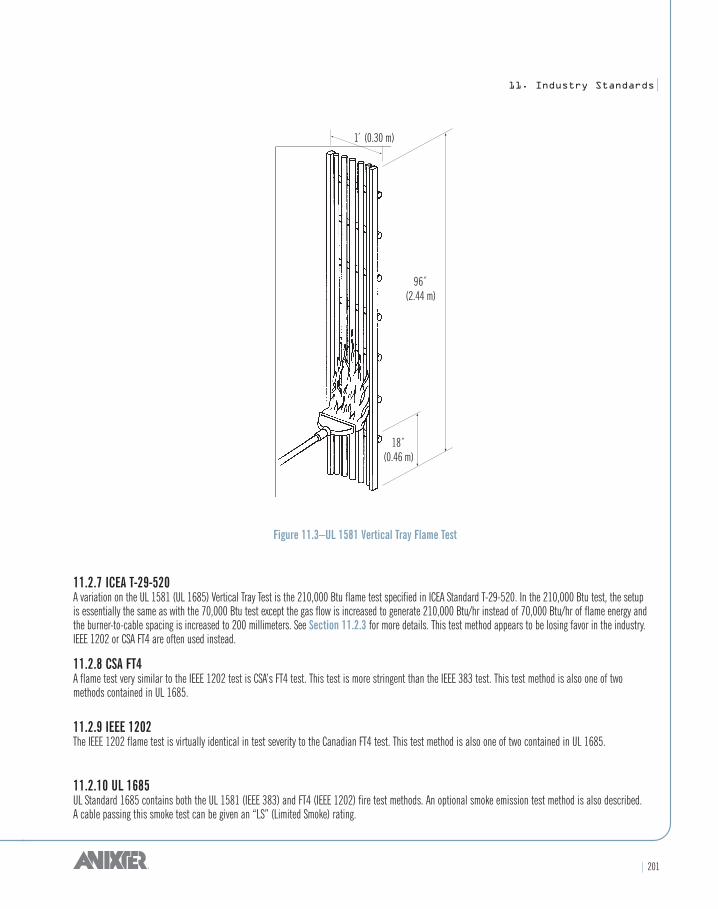
11.2.6 UL 1581 Vertical Tray Flame TestThe Vertical Tray Flame Test is used as a good approximation of flame spread in cables run in groups. A steel ladder type tray 12 inches wide 3 3 inchesdeep and 8 feet long with 1-inch 3 1/2-inch rungs spaced 9 inches apart is mounted vertically on the floor of the test chamber. The center 6 inches of thetray is filled with cable samples in one layer spaced 1/2 cable diameter apart. A 6 to 1 mixture of air to propane is burned using a 10-inch wide ribbon burner.The burner is placed horizontally 3 inches from the back of the tray, 2 feet from the floor and midway between two rungs. The flame is applied for twenty minutes and then removed. A cable passes the vertical tray test if it does not propagate flame to the top of the tray (6 ft.). A cable may continue to burn afterthe burner is shut off; however, the test is not complete until the cable stops burning. The energy output of the burner is 70,000 Btu/hr and the cable is subjected to 23,333 Btus for the test. This test method is also contained in IEEE 383 and in UL 1685. See IEEE 1202 or CSA FT4 for a similar but slightlyharsher test method.
Air Flow
Cable Tray
Burner
Block Wall
8́ (2.44 m)4́
(1.22 m)
7́ (2.13 m)
12́ (3.66 m )
11. Industry Standards|
| 201
Figure 11.3–UL 1581 Vertical Tray Flame Test
11.2.7 ICEA T-29-520A variation on the UL 1581 (UL 1685) Vertical Tray Test is the 210,000 Btu flame test specified in ICEA Standard T-29-520. In the 210,000 Btu test, the setup is essentially the same as with the 70,000 Btu test except the gas flow is increased to generate 210,000 Btu/hr instead of 70,000 Btu/hr of flame energy andthe burner-to-cable spacing is increased to 200 millimeters. See Section 11.2.3 for more details. This test method appears to be losing favor in the industry.IEEE 1202 or CSA FT4 are often used instead.
11.2.8 CSA FT4A flame test very similar to the IEEE 1202 test is CSA’s FT4 test. This test is more stringent than the IEEE 383 test. This test method is also one of two methods contained in UL 1685.
11.2.9 IEEE 1202The IEEE 1202 flame test is virtually identical in test severity to the Canadian FT4 test. This test method is also one of two contained in UL 1685.
11.2.10 UL 1685UL Standard 1685 contains both the UL 1581 (IEEE 383) and FT4 (IEEE 1202) fire test methods. An optional smoke emission test method is also described. A cable passing this smoke test can be given an “LS” (Limited Smoke) rating.
96̋(2.44 m)
1́ (0.30 m)
18̋(0.46 m)

202 |
|11. Industry Standards
11.2.11 UL 1581 VW-1 (Vertical-Specimen) Flame TestThe VW-1 Flame Test was the first flame test developed for studying flame spread on wire and cable. The test measures relative flame propagation of a singlewire or cable. The test procedure is detailed in Underwriters Laboratories Standard 1581, but a general overview of the test is as follows. The fixture used is a bench-mountable 12-inch wide, 14-inch deep and 24-inch high steel box open at the front and top. Clamps hold a single specimen vertically in the center of the box. A Tirrill burner (similar to a Bunsen burner) is mounted on a 20 degree angle block and has a flame 4- to 5-inches high with a 1/2- inch inner blue cone. The burner is placed so the inner cone meets the test sample surface. Ten inches above this point a kraft paper “flag” is placed on the sample facing away from the burner, and cotton batting covers the floor of the chamber to a height 9 inches below the point. The flame is applied to the sample for15 seconds five times (total 75 seconds) with a minimum 15 seconds between flame applications or until burning ceases, whichever is longer. A sample“Passes VW-1” if less than 25 percent of the flag is burned away, the cable doesn’t burn longer than 60 seconds after any flame application, and the cottonbatting is not ignited by dripping particles. The energy output of the burner is less than 3,000 Btu/hr and the test energy is less than 65 Btus. The VW-1 testis very similar to CSA’s FT1 flame test.
Figure 11.4–UL 1581 VW-1 Flame Test
10̋(0.25 m)
Cotton
Indicator Flag

11. Industry Standards|
| 203
11.3 REGULATORY AND APPROVAL AGENCIES
11.3.1 Underwriters Laboratories
Table 11.4–Summary of Wire and Cable Types Covered by UL Standards
UL Standard UL Listing(s) Covered in the Standard
4 Armored Cable AC
13 Power-Limited Circuit Cable CL3P, CL2P, CL3R, CL2R, CL3, CL2, PLTC
44 Rubber Insulated Wires & Cables XHHW, RHH, RHW, RH, SIS, RHW-2, XHHW-2
62 Flexible Cord & Fixture Wire TFN, TFFN, TPT, TST, TS, S, SA, SE, SO, SEO, SOO, ST, STO, STOO, STOW, STOOW
83 Thermoplastic Insulated Wires THW, THHN, THNN, FEP, FEPB, TFE, THW-2, THWN-2, Z, ZW
444 Communication Cables CMP, CMR, CM, CMX
493 Thermoplastic Insulated Underground Feeder & Branch Circuit Cables UF
719 Nonmetallic-Sheath Cables NM, NMC
758 Appliance Wiring Material AWM and all UL “Styles”
814 Gas-Tube-Sign Cable GTO-5, GT0-10, GTO-15
854 Service-Entrance Cables USE, SE, USE-2
1063 Machine-Tool Wires & Cables MTW
1072 Medium Voltage Power Cable MV
1276 Welding Cable WELDING CABLE
1277 Electrical Power & Control Tray Cables with TCOptional Optical-Fiber Members
1426 Electrical Cables for Boats Boat Cable
1569 Metal Clad Cables MC
1581 Reference Standard for Electrical Wires, Cables, and Flexible Cords –
1650 Portable Power Cables W, G, G-GC, PPE
Typical examples of UL’s mark appear below:
Figure 11.5–Typical UL Marks
®

204 |
|11. Industry Standards
11.3.2 National Electrical Code (NEC)
History and ArticlesThe first NEC document was written in 1897 at the insistence of various insurance, electrical, architectural and other interested parties. Up to and including 2008, there have been a total of 51 editions. It is revised on a regular three year schedule. The National Electrical Code is divided into approximately 120 articles.
The Code is published by the National Fire Protection Association (NFPA) as a “recommended standard” and does not become law until it is officially adopted by state or local governments. Enforcement and interpretation of the Code is ultimately the responsibility of “the authority having jurisdiction,” i.e., the local inspector.
The intent of the Code is to ensure the electrical and fire safety of electrical equipment. It does not attempt to ensure the reliability, performance, proper operation or long life of equipment – these considerations are beyond its scope.
National Electrical Code Articles related to the wire and cable industry include:
Article 100 DefinitionsArticle 110 Requirements for Electrical InstallationsArticle 200 Use and Identification of Grounded Conductors
Article 210 Branch CircuitsArticle 215 FeedersArticle 220 Branch-Circuit, Feeder and Service Calculations
Article 225 Outside Branch Circuits and FeedersArticle 230 ServicesArticle 250 Grounding and Bonding
Article 300 Wiring MethodsArticle 310 Conductors for General WiringArticle 310.15 Ampacities for Conductors Rated 0–2000 Volts
Article 310.60 (B) Ampacities of Conductors Rated 2001 to 35,000 VoltsArticle 320 Armored Cable: Type ACArticle 324 Flat Conductor Cable: Type FCC
Article 328 Medium Voltage Cable: Type MVArticle 330 Metal-Clad Cable: Type MCArticle 332 Mineral-Insulated, Metal-Sheathed Cable: Type MI
Article 334 Nonmetallic Sheathed Cable Types NM, NMC and NMSArticle 336 Power and Control Tray Cable: Type TCArticle 338 Service-Entrance Cable: Types SE and USE
Article 340 Underground Feeder and Branch-Circuit Cable: Type UFArticle 344 Rigid Metal Conduit: Type RMCArticle 350 Liquid-Tight, Flexible Metal Conduit: Type LFMC
Article 356 Liquid-Tight, Flexible Nonmetallic Conduit Type: LFMCArticle 358 Electrical Metallic Tubing: Type EMTArticle 362 Electrical Nonmetallic Tubing: Type ENT
Article 392 Cable TraysArticle 396 Messenger Supported WiringArticle 400 Flexible Cords and Cables
Continued on next page >>

11. Industry Standards|
| 205
(Continued)
Article 402 Fixture WiresArticle 409 Industrial Control PanelsArticle 500 Hazardous (Classified) Locations, Classes I, II, and III, Divisions 1 and 2
Article 501 Class I LocationsArticle 502 Class II LocationsArticle 503 Class III Locations
Article 504 Intrinsically Safe SystemsArticle 505 Class I, Zone 0, 1, and 2 LocationsArticle 590 Temporary Installations
Article 604 Manufactured Wiring SystemsArticle 610 Cranes and HoistsArticle 645 Information Technology Equipment
Article 725 Class 1, Class 2, Class 3, Remote-Control, Signaling and Power-Limited CircuitsArticle 727 Instrumentation Tray Cable: Type ITCArticle 760 Fire Alarm Systems
Article 770 Optical Fiber Cables and RacewaysArticle 800 Communication CircuitsArticle 820 Community Antenna Television (CATV) and Radio Distribution Systems
Article 830 Network-Powered Broadband Communication SystemsChapter 9 Tables (Conduit fill, conductor properties, etc.)
Table 11.5– NEC Article 725 – Summary of Remote Control, Signaling and Power-Limited Circuit Types
Circuit Type Circuit Voltage Maximum Current
Class 1 Remote Control and Signaling 0 through 600 Unlimited(Not Power-Limited)
Class 1 Power-Limited 0 through 30 33 Amps
Class 2 Power-Limited 0 through 30 8 Amps(Fire and Shock Safe) 30 through 150 0.005 Amps
Class 3 Power-Limited 30 through 150 10 Amps(Fire Safe Only)
Note: The above is a highly simplified overview only. See Article 725 of the NEC for complete requirements. Class 2 cables must be rated at least 150 volts andClass 3 cables must be rated at least 300 volts, but may not be so marked.

206 |
|11. Industry Standards
11.3.3 International
Table 11.6–Symbols of International Organizations
Agency Country(ies) Represented Symbol
CSA (Canadian Standards Association) Canada
CEBEC (Comite Electrotechnique Belge Service de la Marque) Belgium
DEMKO (Danmarks Electriske Materailkontrol) Denmark
SETI (Electrical Inspectorate Sakiniementie) Finland
CENELEC (European Committee for Electrotechnical Standards) See Note 1.
IEC (International Electrotechnical Commission) More than 60 around the world
ISO (International Standards Organization) More than 60 around the world
IMQ (Istituto Italiano del Marchio di Qualità) Italy
KEMA, KEUR (NV tot Keuring van Elektrotechnische Materialen) Netherlands
NEMKO (Norges Electriske Materallknotroll) Norway
Continued on next page >>
CEBECCEBEC

11. Industry Standards|
| 207
Table 11.6–Symbols of International Organizations (Continued)
Agency Country(ies) Represented Symbol
ÖVE (Österreichischer Verband für Elektrotechnik) Austria
SEMKO (Svenska Electriska Materielkontrollanstalten) Sweden
SEV (Schweizerischen Electrotechnischen Verein) Switzerland
UL (Underwriters Laboratories) USA
UTE (Union Technique de L’Électricité) France
VDE (Verband Deutscher Elektrotechnischer) Germany
Note 1: AustriaBelgiumBulgariaCyprusCzech RepublicDenmarkEstoniaFinlandFranceGermany
GreeceHungaryIcelandIrelandItalyLatviaLithuaniaLuxembourgMaltaNetherlands
NorwayPolandPortugalRomaniaSlovakiaSloveniaSpainSwedenSwitzerlandUnited Kingdom
®