7.active filters using opamp
TRANSCRIPT

09/12/15 Active Filters by Prof.Satheesh MB, INA
Active Filters
Prof.Satheesh Monikandan B
HOD-ECE

09/12/15 Active Filters by Prof.Satheesh MB, INA
IntroductionIntroduction
Filters are circuits that are capable of passing signals within a band of frequencies while rejecting or blocking signals of frequencies outside this band. This property of filters is also called “frequency selectivity”.
Filter can be passive or active filter.
Passive filtersPassive filters: The circuits built using RC, RL, or RLC circuits.
Active filtersActive filters : The circuits that employ one or more op-amps in the design an addition to
resistors and capacitors

09/12/15 Active Filters by Prof.Satheesh MB, INA
Types of Filters
• There are two broad categories of filters:– An analog filter processes continuous-time signals
– A digital filter processes discrete-time signals.
• The analog or digital filters can be subdivided into four categories:– Low pass Filters
– High pass Filters
– Band stop Filters
– Band pass Filters

09/12/15 Active Filters by Prof.Satheesh MB, INA
Analog Filter Responses
H(f)
ffc
0
H(f)
ffc
0
Ideal “brick wall” filter Practical filter

09/12/15 Active Filters by Prof.Satheesh MB, INA
Ideal Filters
Passband Stopband Stopband Passband
Passband PassbandStopband
Lowpass Filter Highpass Filter
Bandstop Filter
PassbandStopband Stopband
Bandpass Filter
M(ω)
M(ω)
ω ω
ω ω
ω c ω c
ω c1ω c1
ω c2ω c2

09/12/15 Active Filters by Prof.Satheesh MB, INA
Passive Filters
• Made up of passive components - resistors, capacitors and inductors
• No amplifying elements (transistors, op-amps, etc) • No signal gain • 1st order - design is simple (just use standard equations to
find resonant frequency of the circuit) • 2nd order - complex equations • Require no power supplies • Buffer amplifiers might be required Desirable to use inductors with high quality factors

09/12/15 Active Filters by Prof.Satheesh MB, INA
Inductor - BIG PROBLEM!
• Physical size, and large inductance values are required. • Tuning inductors to the required values is time-consuming
and expensive for larger quantities of filters.
• Often prohibitively expensive. Difficult to implement at frequencies below 1 kHz. Lossy

09/12/15 Active Filters by Prof.Satheesh MB, INA
Active Filter
• No inductors • Made up of op-amps, resistors and capacitors • Provides arbitrary gain • Generally easier to design • High input impedance prevents excessive loading of the driving
source • Low output impedance prevents the filter from being affected
by the load • Easy to adjust over a wide frequency range without altering the
desired response

09/12/15 Active Filters by Prof.Satheesh MB, INA
ApplicationsApplications
Active filters are mainly used in communication and signal processing circuits.
They are also employed in a wide range of applications such as entertainment, medical electronics, etc.

09/12/15 Active Filters by Prof.Satheesh MB, INA
Op Amp Advantages
• Advantages of active RC filters include:
– Reduced size and weight
– Increased reliability and improved performance
– Simpler design than for passive filters and can realize a wider range of functions as well as providing voltage gain
– In large quantities, the cost of an IC is less than its passive counterpart

09/12/15 Active Filters by Prof.Satheesh MB, INA
Op Amp Disadvantages
• Active RC filters also have some disadvantages:– limited bandwidth of active devices limits the highest
attainable pole frequency and therefore applications nearby 100 kHz (passive RLC filters can be used up to 500 MHz)
– require power supplies (unlike passive filters)– increased sensitivity to variations in circuit parameters
caused by environmental changes compared to passive filters.
• For many applications, particularly in voice and data communications, the economic and performance advantages of active RC filters far outweigh their disadvantages.

09/12/15 Active Filters by Prof.Satheesh MB, INA
Categories of Filters
-3dB
f 2
f
A v(dB)
-3dB
f 1
f
A v(dB)
Low-pass response High-pass response
Low Pass Filters:
Pass all frequencies from dc up to the upper cutoff frequency.
High Pass Filters:
Pass all frequencies that are above its lower cutoff frequency

09/12/15 Active Filters by Prof.Satheesh MB, INA
Categories of Filters
-3dB
f 2
f
A v(dB)
f 1
-3dB
ff 2f 1
A v(dB)
Band Pass Response Band Stop Response
Band Pass Filters:
Pass only the frequencies that fall between its values of the lower and upper cutoff frequencies.
Band Stop (Notch) Filters:
Eliminate all signals within the stop band while passing all frequencies outside this band.
09/12/15 Active Filters by Prof.Satheesh MB, INA
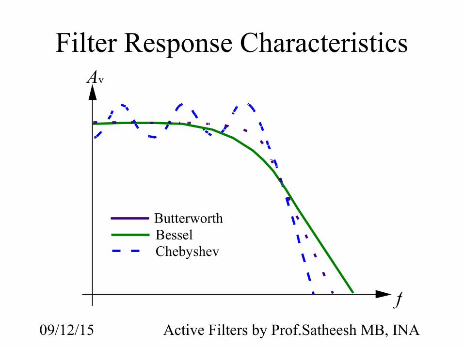
Filter Response CharacteristicsAv
ButterworthBesselChebyshev
f
09/12/15 Active Filters by Prof.Satheesh MB, INA
Actual response
Vo
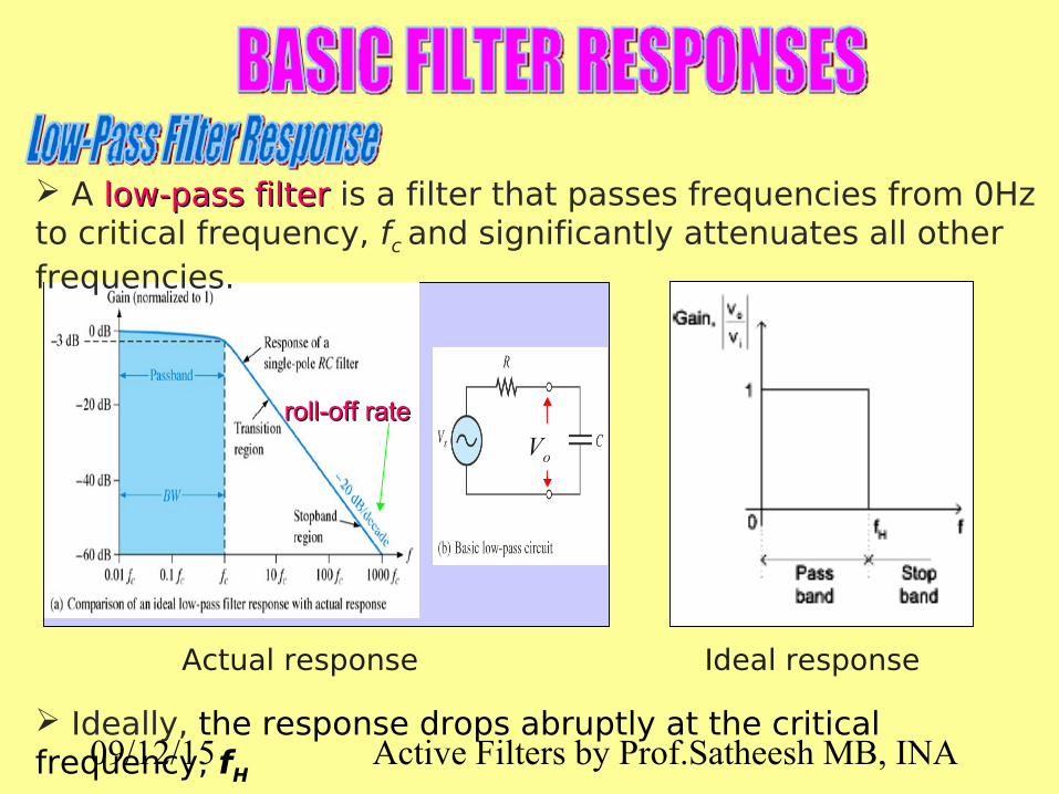
A low-pass filterlow-pass filter is a filter that passes frequencies from 0Hz to critical frequency, fc and significantly attenuates all other frequencies.
Ideal response
Ideally, the response drops abruptly at the critical frequency, fH
roll-off rateroll-off rate
09/12/15 Active Filters by Prof.Satheesh MB, INA
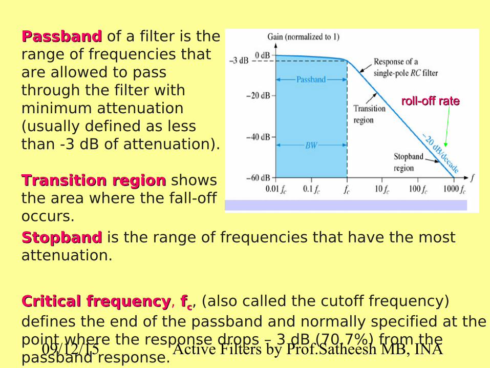
StopbandStopband is the range of frequencies that have the most attenuation.
Critical frequencyCritical frequency, ffcc, (also called the cutoff frequency) defines the end of the passband and normally specified at the point where the response drops – 3 dB (70.7%) from the passband response.
PassbandPassband of a filter is the range of frequencies that are allowed to pass through the filter with minimum attenuation (usually defined as less than -3 dB of attenuation).
Transition regionTransition region shows the area where the fall-off occurs.
roll-off rateroll-off rate

09/12/15 Active Filters by Prof.Satheesh MB, INA
At low frequencies, XC is very high and the capacitor circuit can be considered as open circuit. Under this condition, Vo = Vin or AV = 1 (unity).
At very high frequencies, XC is very low and the Vo is small as compared with Vin. Hence the gain falls and drops off gradually as the frequency is increased.
Vo

09/12/15 Active Filters by Prof.Satheesh MB, INA
The bandwidthbandwidth of an idealideal low-pass filter is equal to ffcc:
BW = f c
The critical frequency of a low-pass RC filter occurs when
XXCC = R = R and can be calculated using the formula below:
f c=1
2π RC

09/12/15 Active Filters by Prof.Satheesh MB, INA
Passive single pole low pass filterR
C VoVi
V o=X C
X C+ RV i
V o=
1jωC1
jωC+ R
V i=1
1+ jω CRV i
H ( jω)=1
1+ jωω0
ωo=1
RCwhere
or
H ( s )=ω0
s+ω0
s= jω
where
φ( ω )=− tan−1( ωω0
)

09/12/15 Active Filters by Prof.Satheesh MB, INA
H ( jω)=1
1+ jω CR
V o=1
1+ jω CRV i
ω → 0 ⇒ |Vo| = |Vi| ← max.
valueω → ∞ ⇒ |Vo| = 0 ← min. value
⇒ |Vo| = ?? ω=1
RC
V o=1
1+ jV i
∣V o∣=1
√12+12∣V i∣=
1
√ 2∣V i∣
ωc=ωo=1
RC (cut-off frequency )
ωc
ω
ov
maxov
2maxo
v
ωc
ω
)( ωjH
2
1
1

09/12/15 Active Filters by Prof.Satheesh MB, INA
Bode Plot (single pole)H ( jω)=
11+ jω CR
=1
1+ j( ωωo )
∣H ( jω)∣=1
√1+( ωωo )
2
∣H ( jω)∣dB=20 log10∣H ( jω)∣=20 log10(1/√1+( ωωo
)2
)⇒
∣H ( jω)∣dB≈−20 log10( ωωo
)
For ω>>ωo
R
C VoVi
Single pole low-pass filter

09/12/15 Active Filters by Prof.Satheesh MB, INA
Single-Pole Passive Filter
• First order low pass filter• Cut-off frequency = 1/RC rad/s• Problem : Any load (or source) impedance
will change frequency response.
vin voutC
R v out
v in
=ZC
R+Z C
=1/ sCR+1 /sC
¿1sCR+1
=1/ RCs+1/ RC

09/12/15 Active Filters by Prof.Satheesh MB, INA
Single-Pole Active Filter
• Same frequency response as passive filter.• Buffer amplifier does not load RC network.• Output impedance is now zero.
vin vout
C
R

09/12/15 Active Filters by Prof.Satheesh MB, INA
The critical frequencycritical frequency, ffcc is determined by the values of R and C in the frequency-selective RC circuit.
Each RCRC set of filter components represents a polepole.
Greater roll-off ratesGreater roll-off rates can be achieved with more polesmore poles.
Each pole represents a -20dB/decade-20dB/decade increase in roll-off.
One-pole (first-order)
low-pass filter.

09/12/15 Active Filters by Prof.Satheesh MB, INA
The number of poles determines the roll-off rate of the filter. For example, a Butterworth response produces -20dB/decade/pole. This means that:
One-pole (first-order)One-pole (first-order) filter has a roll-off of -20 dB/decade Two-pole (second-order)Two-pole (second-order) filter has a roll-off of -40 dB/decade Three-pole (third-order)Three-pole (third-order) filter has a roll-off of -60 dB/decade

09/12/15 Active Filters by Prof.Satheesh MB, INA
The number of filter poles can be increased by cascadingcascading. To obtain a filter with three poles, cascade a two-pole with one-pole filters.
Three-pole (third-order) low-pass filter.

09/12/15 Active Filters by Prof.Satheesh MB, INA
A high-pass filterhigh-pass filter is a filter that significantly attenuates or rejects all frequencies below fc and passes all frequencies above fc.
The passband of a high-pass filter is all frequencies above the critical frequency..
Vo
Actual response Ideal response
Ideally, the response rises abruptly at the critical frequency, fL

09/12/15 Active Filters by Prof.Satheesh MB, INA
Advantages of active filters over passive filters
1. By containing the op-amp, active filters can be designed to provide required gain, and hence no no signal attenuationsignal attenuation as the signal passes through the filter.
2. No loading problemNo loading problem, due to the high input impedance of the op-amp prevents excessive loading of the driving source, and the low output impedance of the op-amp prevents the filter from being affected by the load that it is driving.
3. Easy to adjust over a wide frequency rangeEasy to adjust over a wide frequency range without altering the desired response.

09/12/15 Active Filters by Prof.Satheesh MB, INA
Single-pole active low-pass filter and response curve.
This filter provides a roll-off rate of -20 dB/decade above the critical frequency.
09/12/15 Active Filters by Prof.Satheesh MB, INA
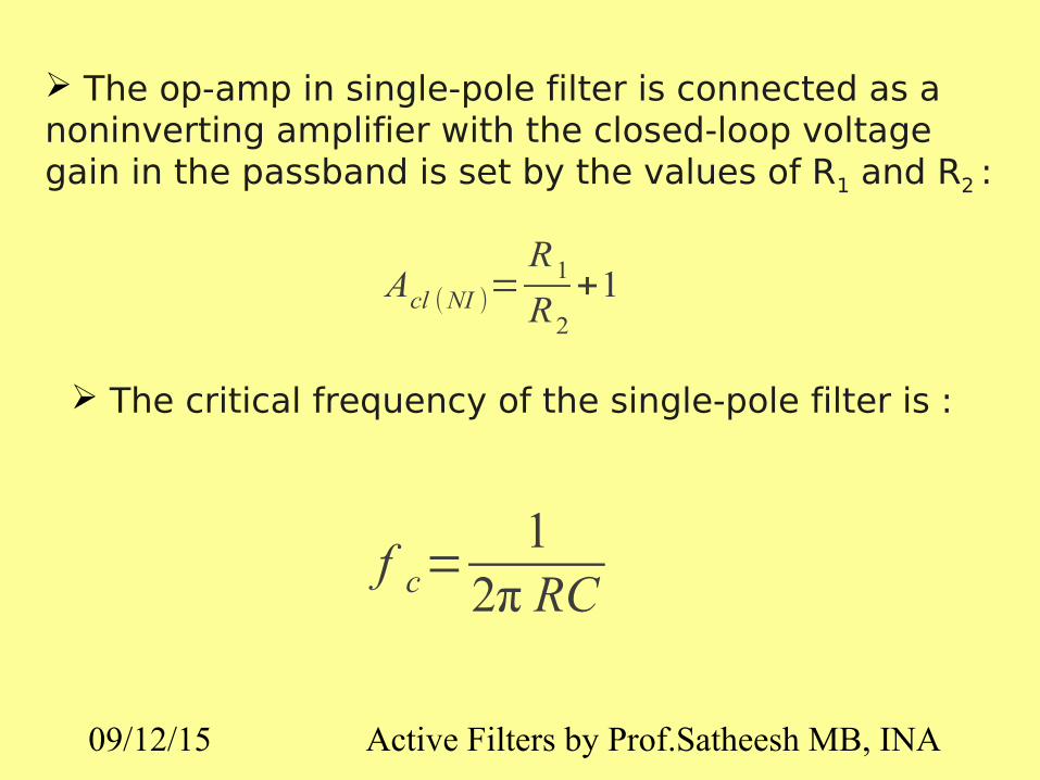
The op-amp in single-pole filter is connected as a noninverting amplifier with the closed-loop voltage gain in the passband is set by the values of R1 and R2 :
Acl (NI )=R1
R2
+1
The critical frequency of the single-pole filter is :
f c=1
2π RC

09/12/15 Active Filters by Prof.Satheesh MB, INA
Sallen-KeySallen-Key is one of the most common configurations for a second ordersecond order (two-pole) filter.
Basic Sallen-Key low-pass filter.
There are two low-pass RC circuits that provide a roll-off of -40 roll-off of -40 dB/decade above fdB/decade above fcc
(assuming a Butterworth characteristics).
One RC circuit consists of RRAA and CCAA, and the second circuit consists of RRBB and CCBB.

09/12/15 Active Filters by Prof.Satheesh MB, INA
The critical frequency for the Sallen-Key filter is :
f c=1
2π √ RA RB C AC B
For RA = RB = R and CA = CB = C, thus the critical frequency :
f c=1
2π RC

09/12/15 Active Filters by Prof.Satheesh MB, INA
A three-pole filterA three-pole filter is required to provide a roll-off rate of -60 dB/decade-60 dB/decade. This is done by cascading a two-pole two-pole Sallen-Key low-pass filterSallen-Key low-pass filter and a single-pole low-pass filtersingle-pole low-pass filter.
Cascaded low-pass filter: third-order configuration.

09/12/15 Active Filters by Prof.Satheesh MB, INA
Cascaded low-pass filter: fourth-order configuration.
A four-pole filterA four-pole filter is required to provide a roll-off rate of -80 dB/decade-80 dB/decade. This is done by cascading a two-pole two-pole Sallen-Key low-pass filterSallen-Key low-pass filter and a two-pole Sallen-Key low-two-pole Sallen-Key low-pass filter.pass filter.

09/12/15 Active Filters by Prof.Satheesh MB, INA
f c=1
2π RC
• Both stages must have the same fc. Assume equal-value of capacitor
C=1
2πf c R=0 .033 μF
CA1=CB1=CA2=CB2=0.033µf
• Determine the capacitance values required to produce a critical frequency of 2680 Hz if all resistors in RC low pass circuit is 1.8kΩ

09/12/15 Active Filters by Prof.Satheesh MB, INA
Low-Pass and High-Pass Designs
High Pass Low Pass
v out
v in
=11sCR
+1=
11+sRCsCR
¿sRCRC ( s+1/ RC )
=s( s+1/ RC )
vout
v in
=1/ RC
s+1/ RC

09/12/15 Active Filters by Prof.Satheesh MB, INA
The critical frequency of a high-pass RC filter occurs when
XXCC = R = R and can be calculated using the formula below:
f c=1
2π RC

09/12/15 Active Filters by Prof.Satheesh MB, INAf c=
12π RC
R=X c
Figure below shows the basic High-Pass filter circuit :
R=1
2πf c C
R=1
ωcC
At critical frequency,
Resistance = Capacitance
So, critical frequency ;

09/12/15 Active Filters by Prof.Satheesh MB, INA
In high-pass filters, the roles of the capacitorcapacitor and resistorresistor are reversedreversed in the RC circuits as shown from Figure (a). The negative feedback circuit is the same as for the low-pass filters.
Figure (b) shows a high-pass active filter with a -20dB/decade roll-off
Single-pole active high-pass filter and response curve.
09/12/15 Active Filters by Prof.Satheesh MB, INA
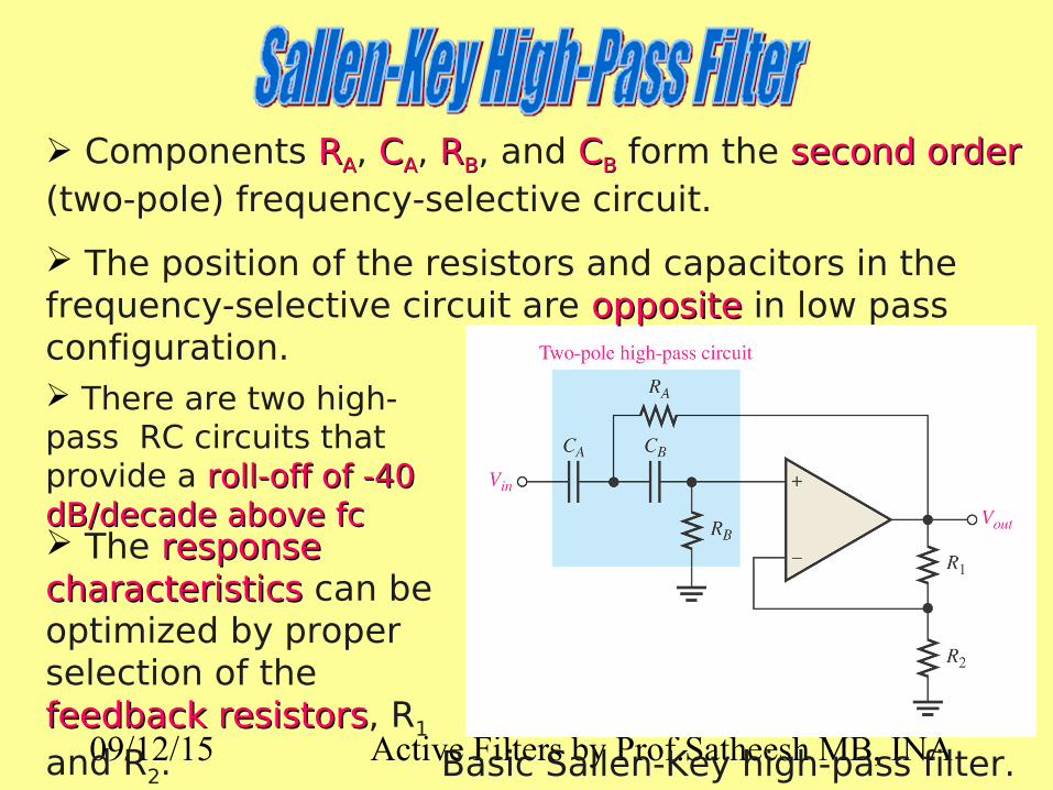
Components RRAA, C CAA, RRBB, and CCBB form the second ordersecond order (two-pole) frequency-selective circuit.
The position of the resistors and capacitors in the frequency-selective circuit are oppositeopposite in low pass configuration.
The response response characteristicscharacteristics can be optimized by proper selection of the feedback resistorsfeedback resistors, R1 and R2. Basic Sallen-Key high-pass filter.
There are two high-pass RC circuits that provide a roll-off of -40 roll-off of -40 dB/decade above fcdB/decade above fc

09/12/15 Active Filters by Prof.Satheesh MB, INA
The critical frequency for the Sallen-Key filter is :
f c=1
2π √ RA RB C AC B
For RA = RB = R and CA = CB = C, thus the critical frequency :
f c=1
2π RC
09/12/15 Active Filters by Prof.Satheesh MB, INA
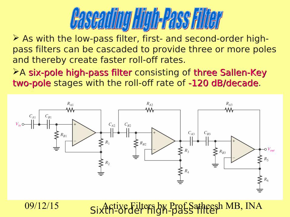
As with the low-pass filter, first- and second-order high-pass filters can be cascaded to provide three or more poles and thereby create faster roll-off rates. A six-pole high-pass filtersix-pole high-pass filter consisting of three Sallen-Key three Sallen-Key two-poletwo-pole stages with the roll-off rate of -120 dB/decade-120 dB/decade.
Sixth-order high-pass filter

09/12/15 Active Filters by Prof.Satheesh MB, INA
A band-pass filterband-pass filter passes all signals lying within a band between a lower-frequency limitlower-frequency limit and upper-upper-frequency limitfrequency limit and essentially rejects all other frequencies that are outside this specified band.
Actual response Ideal response

09/12/15 Active Filters by Prof.Satheesh MB, INA
The bandwidth (BW)bandwidth (BW) is defined as the differencedifference between the upper critical frequency (fupper critical frequency (fc2c2)) and the lower critical frequency (flower critical frequency (fc1c1)).
BW = f c2− f c1
09/12/15 Active Filters by Prof.Satheesh MB, INA
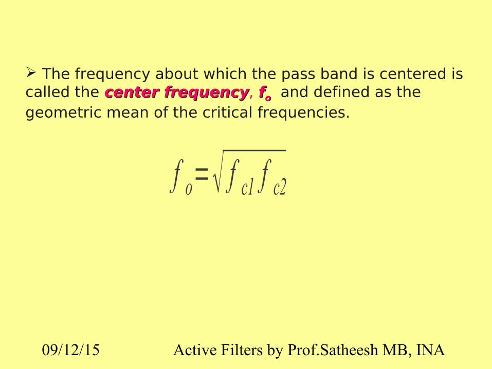
f o=√ f c1 f c2
The frequency about which the pass band is centered is called the center frequencycenter frequency, ffoo and defined as the geometric mean of the critical frequencies.

09/12/15 Active Filters by Prof.Satheesh MB, INA
The quality factor (Q)quality factor (Q) of a band-pass filter is the ratio of the center frequency to the bandwidth.
Q=f o
BW
The quality factor (Q) can also be expressed in terms of the damping factor (DF) of the filter as :
Q=1
DF
The higher value of Q, the narrower the bandwidth and the better the selectivity for a given value of fo.
(Q>10) as a narrow-band or (Q<10) as a wide-band

09/12/15 Active Filters by Prof.Satheesh MB, INA
OP AMP BANDPASS FILTERS
A bandpass filter consists of three separate components
1. A unity-gain low-pass filter whose cutoff frequency is wc2, the larger of the two cutoff frequencies
2. A unity-gain high-pass filter whose cutoff frequency is wc1, the smaller of the two cutoff frequencies
3. A gain component to provide the desired level of gain in the passband.
These three components are cascaded in series. The resulting filter is called a broadband bandpass filter, because the band of frequencies passed is wide.

09/12/15 Active Filters by Prof.Satheesh MB, INA
R A 1
R B 1
R A 2 R B 2
C A 1
C B 1
C A 2
C B 2R 1
R 2
R 3
R 4
V in V out
Two-pole high-pass Two-pole low-pass
Band-pass filter is formed by cascading a two-pole high-pass and two pole low-pass filter.
Each of the filters shown is Sallen-Key Butterworth configuration, so that the roll-off rate are -40dB/decade.
09/12/15 Active Filters by Prof.Satheesh MB, INA
A v (dB)
0
−3
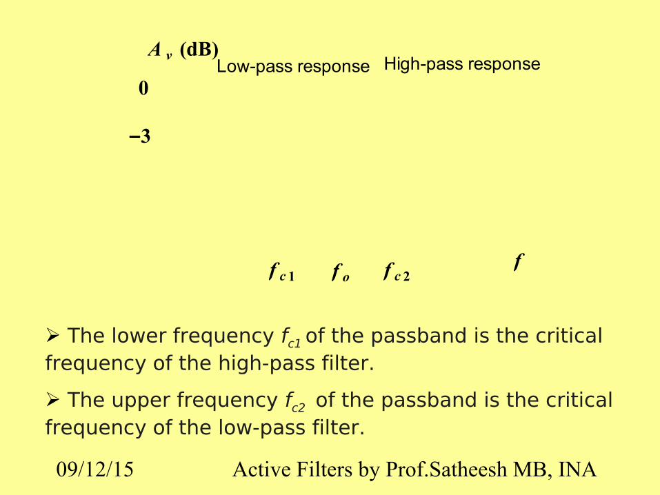
Low-pass response High-pass response
f c 1 f c 2f of
The lower frequency fc1 of the passband is the critical frequency of the high-pass filter.
The upper frequency fc2 of the passband is the critical frequency of the low-pass filter.

09/12/15 Active Filters by Prof.Satheesh MB, INA
f 0=√ f c1 f c2f c1=1
2π√ R A1 RB1C A1C B1
f c2=1
2π √ RA2 RB2C A2C B2
The following formulas express the three frequencies of the band-pass filter.
If equal-value components are used in implementing each filter,
f c=1
2π RC

09/12/15 Active Filters by Prof.Satheesh MB, INA
It has outputs for low-pass, high-pass, and band-pass.
The center frequency is set by the integrator RC circuits.
The critical frequency of the integrators usually made equal
The band-pass output peaks sharply the center frequency giving it a high Q.

09/12/15 Active Filters by Prof.Satheesh MB, INA
Band-stop filterBand-stop filter is a filter which its operation is oppositeopposite to that of the band-pass filter because the frequencies withinwithin the bandwidth are rejectedrejected, and the frequencies above ffc1c1 and ffc2c2 are passedpassed.
Actual response For the band-stop filter, the bandwidthbandwidth is a band of frequencies between the 3 dB points, just as in the case of the band-pass filter response.
Ideal response

09/12/15 Active Filters by Prof.Satheesh MB, INA
OP AMP BANDREJECT FILTERS
Like the bandpass filters, the bandreject filter consists of three separate components
• The unity-gain low-pass filter has a cutoff frequency of wc1, which is the smaller of the two cutoff frequencies.
• The unity-gain high-pass filter has a cutoff frequency of wc2, which is the larger of the two cutoff frequencies.
• The gain component provides the desired level of gain in the passbands.
The most important difference is that these components are connected in parallel and using a summing amplifier.

09/12/15 Active Filters by Prof.Satheesh MB, INA
Band-Stop (Notch) FilterThe notch filter is designed to block all frequencies that fall within its bandwidth. The circuit is made up of a high pass filter, a low-pass filter and a summing amplifier. The summing amplifier will have an output that is equal to the sum of the filter output voltages.
f 1
f 2
v in v out
Low passfilter
High passfilter
Summingamplifier
Σ
-3dB
f
f2f1
Av(dB)
low-pass high-pass
Block diagram Frequency response

09/12/15 Active Filters by Prof.Satheesh MB, INA
+
+vi
RLRL
+
RH
RH
CH
+vo
+
Ri
Ri
Rf
CL

09/12/15 Active Filters by Prof.Satheesh MB, INA
There are 3 characteristics of filter response :
i)i) Butterworth Butterworth characteristic
ii)ii) Chebyshev Chebyshev characteristic
iii) BesselBessel characteristic.
Each of the characteristics is identified by the shape of the response curve.
Comparative plots of three types of filter response characteristics.

09/12/15 Active Filters by Prof.Satheesh MB, INA
Filter response is characterized by flat amplitude responseflat amplitude response in the passband.
Provides a roll-off rate of -20 dB/decade/pole.
Filters with the Butterworth response are normally used when all frequencies in the passband must have the same gainsame gain.

09/12/15 Active Filters by Prof.Satheesh MB, INA
Filter response is characterized by overshootovershoot or ripplesripples in the passband.
Provides a roll-off rate greater than -20dB/decade/pole.
Filters with the Chebyshev response can be implemented with fewerfewer polespoles and less complexless complex circuitrycircuitry for a given roll-off Rate.

09/12/15 Active Filters by Prof.Satheesh MB, INA
Filter response is characterized by a linear characteristiclinear characteristic, meaning that the phase shift increases linearly with frequency.
Filters with the Bessel response are used for filtering pulse waveforms without distorting the shape of waveform.

09/12/15 Active Filters by Prof.Satheesh MB, INA
The damping factor (DF)damping factor (DF) of an active filter determines which response characteristic the filter exhibits.
This active filter consists of an amplifieran amplifier, a negative a negative feedback circuitfeedback circuit and RC RC circuitcircuit.
The amplifier and feedback are connected in a non-inverting configurationnon-inverting configuration.
General diagram of active filter

09/12/15 Active Filters by Prof.Satheesh MB, INA
The value of DF required to produce a desired response characteristics depends on orderorder (number of poles) of the filter.
A pole (single pole) is simply one resistorone resistor and one capacitorone capacitor.
The more polesmore poles filter has, the faster its roll-off rate

09/12/15 Active Filters by Prof.Satheesh MB, INA
Pole
• A pole is nothing more than an RC circuit
• n-pole filter → contains n-RC circuit.
09/12/15 Active Filters by Prof.Satheesh MB, INA
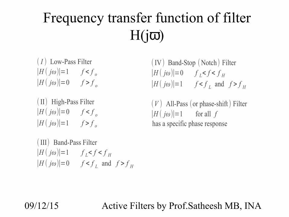
Frequency transfer function of filter H(jω)
( I ) Low-Pass Filter∣H ( jω)∣=1 f < f o
∣H ( jω)∣=0 f > f o
( II) High-Pass Filter∣H ( jω)∣=0 f < f o
∣H ( jω)∣=1 f > f o
( III) Band-Pass Filter∣H ( jω)∣=1 f L< f < f H
∣H ( jω)∣=0 f < f L and f > f H
( IV ) Band-Stop ( Notch ) Filter∣H ( jω)∣=0 f L< f < f H
∣H ( jω)∣=1 f < f L and f > f H
(V ) All-Pass (or phase-shift ) Filter∣H ( jω)∣=1 for all fhas a specific phase response

09/12/15 Active Filters by Prof.Satheesh MB, INA
Higher order active filters have multiple poles in their transfer functions, resulting in a sharper transition from the passband to the stopband and thus a more nearly ideal frequency response.
Higher Order Op Amp Filters

09/12/15 Active Filters by Prof.Satheesh MB, INA
The bandwidth of a low-pass filter is the same as the upper critical frequency.
The bandwidth of a high-pass filter extends from the lower critical frequency up to the inherent limits of the circuit.
The band-pass passes frequencies between the lower critical frequency and the upper critical frequency.

09/12/15 Active Filters by Prof.Satheesh MB, INA
A band-stop filter rejects frequencies within the upper critical frequency and upper critical frequency.
The Butterworth filter response is very flat and has a roll-off rate of –20 dB
The Chebyshev filter response has ripples and overshoot in the passband but can have roll-off rates greater than –20 dB

09/12/15 Active Filters by Prof.Satheesh MB, INA
The Bessel response exhibits a linear phase characteristic, and filters with the Bessel response are better for filtering pulse waveforms.
A filter pole consists of one RC circuit. Each pole doubles the roll-off rate.
The Q of a filter indicates a band-pass filter’s selectivity. The higher the Q the narrower the bandwidth.
The damping factor determines the filter response characteristic.