7660 ax/ex 7665 ax/ex - equipementdld.comequipementdld.com/downloads/coats tire changers/70xx tire...
TRANSCRIPT

1601 J. P. Hennessy Drive, LaVergne, TN USA 37086-3565 615/641-7533 800/688-6359 Manual Part No.: 8183762 00HENNESSY INDUSTRIES INC. Manufacturer of AMMCO®, COATS® and BADA® Automotive Service Equipment and Tools. Revision: 09/98
Safety InstructionsOperating Instructions
Installation InstructionsMaintenance Instructions
READ these instructions before placing unit inservice. KEEP these and other materials deliveredwith the unit in a binder near the machine forease of reference by supervisors and operators.
®
7660 AX/EX7665 AX/EXRim Clamp®
Tire ChangerFor servicing single pieceautomotive and most lighttruck tire/wheel assemblies

Table of Contents
Definitions of Hazard Levels ................................1
Owner’s Responsibility ........................................1
Principal Operating Parts .....................................2
Operating Instructions .........................................3
Bead Loosening and Demounting ....................3
Mounting ...........................................................6
Inflation ..................................................................7
Bead Sealing ....................................................7
Bead Seating ....................................................8
Inflation .............................................................8
Performance, Custom, and Aluminum Wheels ..9
Aluminum and Custom Wheels ........................9
Performance Tires and Wheels • Demounting .9
Performance Tires and Wheels • Mounting ....11
Custom and Special Wheels ..............................12
Tube Type Tires ..................................................12
Stages of Inflation ...............................................13
Bead Seal .......................................................13
Bead Seat .......................................................13
Inflation ...........................................................13
Mis-Matched Tires and Wheels ..........................13
Maintenance Instructions ...................................14
Installation Instructions .....................................15
Critical Safety Instructions .................Back Cover
Operator Protective Equipment
Personal protective equipment helps make tirechanging safer. However, equipment does not takethe place of safe operating practices. Always weardurable work clothing during tire service activity.Shop aprons or shop coats may also be worn, how-ever loose fitting clothing should be avoided. Tightfitting leather gloves are recommended to protectoperator’s hands when handling worn tires andwheels. Sturdy leather work shoes with steel toesand oil resistant soles should be used by tire ser-vice personnel to help prevent injury in typical shopactivities. Eye protection is essential during tire ser-vice activity. Safety glasses with side shields, gog-gles, or face shields are acceptable. Back beltsprovide support during lifting activities and are alsohelpful in providing operator protection.Consideration should also be given to the use ofhearing protection if tire service activity is per-formed in an enclosed area, or if noise levels arehigh.
Failure to follow danger,warning, and cautioninstructions may lead to
serious personal injury or death to operator orbystander or damage to property. Do not oper-ate this machine until you read and understandall the dangers, warnings and cautions in thismanual. Download a copy of the manual fromour website at www.ammcoats.com, or for fur-ther information, contact:
Hennessy Industries, Inc.1601 J.P. Hennessy DriveLaVergne, TN 37086-3565(615) 641-7533 or (800) 688-6359www.ammcoats.com
WARNING
For additonal tire, wheel, and/or inflation informationcontact the following:
RUBBER MANUFACTURERS ASSOCIATION1400 K Street N.W.Washington, DC 20005(202) 682-4800www.rma.com
TIRE GUIDES, INC.The Tire Information Center1101-6 South Rogers CircleBoca Raton, FL 33487-2795(561) 997-9229www.tireguides.com

Definitions of Hazard Levels
Identify the hazard levels used in this manual withthe following definitions and signal words:
DANGERWatch for this symbol:
It Means: Immediate hazards which will result insevere personal injury or death.
WARNINGWatch for this symbol:
It Means: Hazards or unsafe practices which couldresult in severe personal injury or death.
CAUTIONWatch for this symbol:
It Means: Hazards or unsafe practices which mayresult in minor personal injury or product or propertydamage.
Watch for this symbol! It means BE ALERT!Your safety, or the safety of others, is involved!
Owner’s Responsibility
To maintain machine and user safety, theresponsibility of the owner is to read and fol-low these instructions:
• Follow all installation instructions.
• Make sure installation conforms to allapplicable Local, State, and FederalCodes, Rules, and Regulations; such asState and Federal OSHA Regulations andElectrical Codes.
• Carefully check the unit for correct initialfunction.
• Read and follow the safety instructions.Keep them readily available for machineoperators.
• Make certain all operators are properlytrained, know how to safely and correctlyoperate the unit, and are properly super-vised.
• Allow unit operation only with all parts inplace and operating safely.
• Carefully inspect the unit on a regularbasis and perform all maintenance asrequired.
• Service and maintain the unit only withauthorized or approved replacementparts.
• Keep all instructions permanently with theunit and all decals on the unit clean andvisible.
DANGER
CAUTION
WARNING
Explosion Hazard
Never inflatetire abovemanufacturer's rec-ommended pressureafter bead is seated.
DANGER DANGER
Explosion Hazard
Never exceed 40 PSIwhile seating beads.
7650/7655AX/EX Rim Clamp Tire Changer • 1

Principal Operating Parts
Know Your UnitCompare this illustration with the unit before placingit into service. Maximum performance and safety willbe obtained only when all persons using the unit arefully trained in its parts and operation. Each usershould learn the function and location of all controls.Prevent accidents and injuries by ensuring the unit isproperly installed, operated, and maintained.
Inflation Guard — Tubular structure to helpprotect operator from physical danger during
inflation process.
Inflation Control Panel — Inflation of tire is con-trolled by these two levers. Both levers must be
actuated from behind the barrier tubes to inflate tire.
Inflation Pedal — Three position pedal thatallows inflation of tires through air hose and clip-
on chuck.
Clamp Control Pedal — Three position pedalthat opens and closes rim clamps.
Table Top Pedal — Three position pedal thatcontrols rotation of table top.
Bead Loosener Shoe — Pivoting shoe forloosening tire beads.
Bead Loosener Handle/Button — Controlsoperation of bead loosener shoe.
Combination Mount/Demount Head —Mounts and demounts tire from wheel.
Swing Arm Adjustment Knob — Adjustsswing arm/vertical slide assembly for proper
horizontal positioning of mount/demount head.
Air Inflation Gauge — Registers tire pressurewhen clip-on chuck is attached to valve stem
and inflation petal is released.
Release Valve — Allows the manual release ofair pressure from tire.
Robotic Arm Control Valve — ControlsVertical Movement of Robotic Arm Cylinder.
Table Top — Rotating chuck for tire changing.
Clamps — Secures wheel to table top for tirechanging.
Bead Sealing Nozzles — Expands tire side-wall to bead seat area of rim to seal and allow
inflation.
Lube Bottle — Dispenser for rubber lubricant.
Oil Check Dipstick — For transmission oillevel.
Bead Lifting Tool — Used to lift and positiontire bead correctly on mount/demount head.
Pressure Safety Valve — The high pressuresafety valve is set to exhaust at line pressures
above 185 PSI.
Vertical Slide Locking Handle — Locks andunlocks vertical slide and sets correct vertical
position to maintain head/wheel clearance.
Bead Roller Tool — Used to apply pressureagainst sidewall of tire.
2 • 7660/7665AX/EX Rim Clamp Tire Changer
1
2
8
7
6
5
4
3
9
10
11
12
13
14
15
16
17
18
1
2
3
4
6
7
8
91011
12
13
14
15
16
17
18
20
19
19
21
5
20
21

OPERATING INSTRUCTIONS
The unit must be properly operated and properlymaintained to help avoid accidents that could dam-age the unit and injure the operator or bystanders.This section of the Operating Instructions manualreview basic operations and use of controls. Theseinstructions should be reviewed with all employeesbefore they are allowed to work with the machine.Keep these instructions near the machine for easyreference.
BEAD LOOSENING AND DEMOUNTING
This machine may operatedifferently from machinesyou have previously oper-
ated. Practice with a regular steel wheel and tirecombination to familiarize yourself with themachine’s operation and function.
A. Remember to remove all weights from both sidesof the wheel. Weights left on back side of wheel maycause the wheel to be clamped unlevel. This mayresult in the combination mount/demount head con-tacting the rim causing scratches. On alloy wheels,always rotate the wheel one turn after setting thehead to insure proper wheel chucking.
B. Always review nicks and scratches with owners ofexpensive wheel and tire combinations prior to ser-vicing.
C. Review the performance wheel section of thismanual prior to servicing performance tire/wheelcombinations.
1. Deflate tire completely by removing the valvecore from the valve stem (Figure 1).
Figure 1 – Remove Valve Core to Deflate Tire
NOTE: Loosening the beads on a partially orfully inflated tire is unsafe and causes excess move-ment and friction against the bumper pads andexcessive wear on pivots. Deflate the tire completelyto prolong the life of your machine.
D. Always loosen the bead on the narrow side of thewheel’s drop center first. See Figure 4 for moreinformation on the drop center.
E. The clamps on the table top may extend beyondthe table top itself. To avoid damaging the clamps,move them to their full inward position before posi-tioning a tire for bead loosening.
F. Use extra care in positioning the bead loosenershoe on larger wheels/tires, and on alloy wheels.Make sure the shoe rests next to but not on the rim,and not on the tire sidewall.
2. Pull the bead loosener shoe away from themachine and roll wheel into position. The valvestem should be in the 2 o’clock posit ion.Position the bead loosener shoe against the tirenext to, but not on, the rim. Press the button onthe bead loosener shoe handle to actuate theshoe and loosen the bead. It may be necessaryto loosen the bead in multiple locations aroundthe tire (Figure 2).
Figure 2 – Position Tire and Bead Loosener Shoe
3. Turn wheel around and repeat loosening pro-cedure on the other side of the wheel. Thisshould be the long side of the drop center (seeFigure 4).
G. It will be easier to clamp the wheel to the tabletop if the lower bead is loosened last.
4. Apply tire manufacturer’s approved rubber lubri-cant liberally to entire circumference of both tirebeads after loosening (Figure 3).
Figure 3 – Apply Rubber Lubricant to Tire Beads
7660/7665AX/EX Rim Clamp Tire Changer • 3
CAUTION
Valve Stem

5. Determine the mounting side of the wheel. Themounting side is the narrow side of the dropcenter. (Tire removed in Figure 4 for clarity.)
Figure 4 – Determining Mounting Side of Wheel
6. Place tire/wheel assembly on table top withmounting side up (Figure 5). Use the clamp con-trol pedal to move the clamps inward (pushpedal down) or outward (toggle pedal up).Clamp steel wheels from the inside (clampspush outward against wheel). Clamp mag andcustom wheels from the outside (clamps pushinward against the outside rim edge). Refer tothe Performance Tires and Wheels section.
Figure 5 – Place Tire/Wheel Assembly on Table Top
7. Move the swing arm into position. Pull the lock-ing handle forward to release the slide. Pushdown on the top of the vertical slide to movethe demount head into contact with the rimedge. Push locking handle back to lock slideinto place. As the slide is locked, the mount/de-mount head will move upward approximately1/8 inch from rim edge (Figure 6).
Figure 6 - PositionMount/Demount Tool
8. The mount /demount head rollershould be in contactwith the rim edge.Turn the swing armadjusting knob tomove the roller awayfrom the rim 1/8 to 1/4inch (Figure 7).
Figure 7 - Adjust Swing Arm to Position Head Roller
9. Check metal head positioning. Mount/demountmetal head should be positioned with 1/8 to 3/16inch clearance between the top of the rim edgeand the bottom of the head, and 1/8 to 1/4 inchclearance between the rim edge and the headroller. This clearance will be maintained as longas the locking handle and adjustment knob arenot changed. The operator may swing the armout of the way and back into place again withoutneeding to reposition the head (when changinga like set of wheels) (Figure 8).
Figure 8 - Proper (Metal) Mount/Demount Head Position
10. Check plastic head positioning. Mount/demountplastic head should be positioned with 1/16 to1/8 inch clearance between the top of the rimedge and the bottom of the head, and 1/16 to1/8 inch clearance between the rim edge andthe inside surface of the head. This clearancewill be maintained as long as the locking handleand adjustment knob are not changed. Theoperator may swing the arm out of the way and
back into place againwithout needing toreposition the headwhen changing a likeset of wheels (Figure9).
Figure 9 - Proper (Plastic)Mount/Demount HeadPosition
Narrow Side
Long Side
Drop Center
1/8" to 1/4"
3/16" to 1/8"
1/16" to 1/8"
1/16" to 1/8"
4 • 7050/7055/7060/7065 AX/EX Rim Clamp Tire Changer

H. The vertical tool clearance may change withmachine use and should be inspected often. Failureto maintain the proper clearance may result in dam-age to the wheel rim and/or tire.
Figure 10 - Insert Bead Lifting Tool
11. Insert the smooth curved end of the bead liftingtool over the forward end of the demount headand below the top bead of the tire. Use your freehand to press down on the tire opposite the headto help with tool insertion (Figure 10).
Figure 11 - Lift Bead Over Demount Head
12. Push the bead lifting tool down towards thewheel to lift the tire bead up and over the knobportion of the demount head. Hold the tool andbead in this position (Figure 11).
13. Depress the table top pedal to rotate the wheelclockwise. The demount head will guide theupper bead up and over the edge of the wheel.
J. Push down on the tire across from demount headduring table top rotation to utilize the drop centerarea of the wheel. This reduces the tensional forceon the top or first bead during demount (Figure 10).
Figure 12 - Demounting Lower Bead
14. Lift and hold the tire at an angle so that the lowerbead is resting in the drop center directly acrossfrom the demount head, and is loose below thedemount head (Figure 12). Insert the smoothcurved end of the bead lifting tool down over theforward end of the mount/demount tool andbelow the lower bead. Lift the bead up and overthe knob on the demount head (Figure 13).
Figure 13 - Guide Lower Bead Over Tool Head
15. Depress the table top pedal to rotate the wheel.The demount head will guide the bead up andover the edge of the wheel. Continue rotationuntil lower bead is demounted.
K. With tube-type tires, demount the upper bead andremove the tube before demounting the lower bead.
L. Table top rotation can be stopped at any time byremoving your foot from the rotation pedal.
M. Normal table top rotation for demounting is clock-wise. Depress the table top pedal to rotate this direc-tion. To rotate the table top counterclockwise, lift thepedal up with your toe.
At times during the mount-ing and demounting proce-dure, the bead lifting tool
may encounter resistance or come under load.Keep one hand firmly on the tool to avoid possibletool disconnect. Use the reversing feature to backout of jam ups.
After successfully completing the demountprocess, proceed to Mounting (page 6).
CAUTION
✓
77050/7055/7060/7065 X/EX Rim Clamp Tire Changer • 5

MOUNTINGThis information must be read and followed carefullyto prevent accidents and injuries during mounting.
Check tire and wheelcarefully before mounting.Make sure the tire bead
diameter and wheel diameter match exactly.Consult the Rubber Manufacturer's Associationfor approved rim widths for tire sizes.
Attempts to force a beadseat on mis-matched tiresand wheels can cause the
tire to violently explode, causing serious person-al injury or death to operator and/or bystanders.
Never mount a tire andwheel handed to you byanyone without checking
both tire and wheel for damage and compatibili-ty. Be extra cautious of persons without knowl-edge of tire service. Keep by-standers out of ser-vice area.
Never mount a damagedtire. Never mount a tire ona rusty or damaged wheel.
Damaged tires and/or wheels may explode.
If you damage the tire beadduring mounting, STOP!,remove the tire and mark it
as damaged. Do not mount a damaged tire.
1. Inspect the wheel closely for damage. Clean thewheel and remove any light corrosion or rubberresidue (Figure 14). Do not attempt to serviceheavily corroded wheels.
Figure 14 - Inspect and Clean the Wheel
2. Inspect tire for damage, paying close attentionto the beads. Verify size match between tire andwheel (Figure 14).
3. Lubricate tire beads liberally with tire manufac-turer’s approved lubricant (Figure 15).
Figure 15 - Lubricate Beads
4. Place tire over wheel and move swing arm intoposition making sure the value stem is at the 6o’clock position. Position tire so that the lower beadis above the rear extension of the mount/demounthead and below the front knob (Figure 16).
Figure 16 - Position Tire Against Mount/Demount Head
5. Depress table top pedal and rotate the wheel tomount the lower bead. Use the drop center ofthe wheel to reduce the tensional force on thebead by pressing down on the tire directlyacross from the mount head. Rotate table topuntil lower bead is fully mounted.
Figure 17 - Mounting Top Bead
6. For top bead, rotate the table top until the valvestem is at the 6 o’clock position . Lift the upperbead up and over the rear of the mount head.With your left hand press down on the tirebetween the mount head and the valve stem tohold the tire in the drop center. Depress tabletop pedal and rotate tire until the bead is mount-ed. Continue to press down on tire during theremaining mounting process (Figure 17).
Do not force the tire ontothe rim. Bead damagecould result making the
tire unsafe and/or creating the risk of injury.
N. If table top rotation stalls, reverse the table topmomentarily until the tire bead is again loose on thewheel. Reposition the tire on the mount head, makesure the bead is correctly positioned in the drop cen-ter of the wheel, then attempt mounting again.
P. For low profile or stiff sidewall tires, use thehelper tool to initially hold the upper bead down inthe drop center, as shown in Figure 33, page 11.
R. For tube type tires, mount the lower bead first,move swing arm out, install the tube, and thenmount the upper bead.
6 • 7660/7665AX/EX Rim Clamp Tire Changer
WARNING
CAUTION
WARNING
CAUTION
WARNING
DANGER

INFLATION
Tire inflation is performed in three steps: bead seal,bead seat, and inflation. These steps are explainedin detail on page 13. Read the explanation of eachstep and understand them thoroughly before pro-ceeding.
Check for proper inflationgauge operation. Accuratepressure readings are
important to safe tire inflation. Refer to theOperating Maintenance section of this manual forinstructions.
If the rim has beenclamped from the outsidefor tire mounting, release
the clamps, lift the tire, and move the clamps tothe center of the table top.
If the wheel/tire has adiameter larger than 14inches and is difficult to
bead seal, the clamps should be moved to thecenter of the table top for the bead seal operation.
Tire failure under pres-sure is hazardous. Thistire changer is not intend-
ed to be a safety device to contain explodingtires, tubes, wheels, or supplemental bead seal-ing equipment that may be attached to thetire/wheel assembly. Inspect tire and wheel care-fully for match, wear, or defects before mount-ing. Always use approved tire bead lubricantduring mounting and inflation.
The inflation pedal, located at therear of the left side of the machine,controls the flow of air through thebead sealing jets and the inflationhose to achieve bead seal.
The bead seating/inflation handcontrol valves are located on theback side of the Inflation Guard.These valves controlair pressure f lowthrough the inflationhose.
NOTE: The clip-onchuck on the endof the hose shouldalways be an openstyle with all parts in proper working order. Onopen style chuck is on that allows air flow whennot attached to a valve, and will flow air whenthe foot valve or hand valves are actuated.
Use the bead seal pedalfor bead sealing only. Donot use this control to
bead seat or inflate the tire. Inflating the tire withthis feature bypasses the pressure liminting fea-tures and could lead to over inflation and possi-ble tire explosion. Do not use this pedal withouta tire and wheel positioned on the table top. Dirtand debris could be blown into the air withenough force to injure the operator orbystanders.
S. The unit is equipped with a pressure limiter toassist the operator with proper tire inflation. Whenthe inflation valves are pushed open simultaneouslyand held, the pressure limiter cycles the air flow onand off, checking the tire pressure during the offcycle. This cycling helps to prevent over inflation ofthe tire. Tires can still be over inflated and explodewith the use of this pressure limiter if all of theinstructions in this manual are not followed com-pletely. The pressure limiter will keep most car andlight truck tires from inflating beyond 60 PSI (smallertires may reach higher pressures). It is the opera-tor's responsibility to follow all instructions and tocontrol inflation pressure as specified in theseinstructions. Check the function of the pressure lim-iter regularly and maintain it according to the instruc-tions provided in this manual for safe and properoperation. Do not tamper with or attempt to adjustthe pressure limiter. Tires requiring inflation beyond60 PSI should be inflated in an inflationchamber/safety cage, or securely mounted on thevehicle if such a device is not available.
Bead Sealing
1. Position valve stem in front of operator and con-nect the inflation hose. Hold tire up againstupper edge of the wheel. Be sure tire’s top beadis over the bottom of the valve stem (Figure 18).
Figure 18 - Lift Tire Upwards for Bead Sealing
2. Depress the bead seal pedal and hold for about2 seconds. The blast of air from the jets willexpand the tire and seal the beads to the rim.
3. Release the bead seal pedal. Verify that bothbeads are completely sealed to the wheel. Repeatthese steps if beads have not sealed. It may benecessary to wait a few seconds for the air stor-age tank to recover before attempting again.
Bead Sealing
7660/7665AX/EX Rim Clamp Tire Changer • 7
CAUTION
CAUTION
CAUTION
DANGER
CAUTION

Explosion Hazard
Never inflatetire abovemanufacturer's rec-ommended pressureafter bead is seated.
T. If tire and wheel are properly lubricated and oper-ator cannot achieve bead seal after 3 or 4 attempts,the valve core may be removed from the valve stemto allow more air flow into the tire to assist with beadseal. After bead seal is achieved, remove the chuckand reinstall the valve core.
Bead SeatingOperator should always standbehind Inflation Guard and keephands, arms, and entire body
away from the tire during the remaining bead seat and infla-tion procedures. Do not permit anyone to stand over the tireas personal injury could result.
Operating a tire changer with adefective, improperly adjusted,or by-passed pressure limiter
could cause an operator to accidentally over-pressurize atire, resulting in a tire explosion with severe injury or deathto the operator or bystanders. Always be sure that the pres-sure limiter is present and is operating properly on themachine at all times.
NEVER increase air pressure toexceed 40 PSI when attemptingbead seat. If operator is unable
to obtain bead seat, something is wrong. Deflate tire com-pletely, inspect the tire and wheel for defects and make surethat the tire and wheel size match. Correct any problemsfound, relubricate both tire beads, and reattempt bead sealand seating procedures.
1. Once the tire is sealed to the rim, move to thearea behind the Inflation Guard and push theinflation valves simultaneously. Both valvesmust be actuated to inject air into the tire.Continue to inject air into the tire in short inter-vals, checking the pressure frequently. Standbehind Inflation Gaurd during bead seat. Keephands, arms, and entire body away from tireduring this procedure.
Tire beads should move outward and "pop" intotheir bead seat position as pressure inside thetire increases. If this does not happen, a prob-lem exists. Investigate carefully for defects andmake sure the tire and wheel sizes match.
Check tire pressure frequently.Never exceed 40 PSI while seat-ing beads. Once seated, never
exceed tire manufacturer's recommended air pressure. Tirescan explode, especially if they are inflated beyond their lim-its. At all pressure levels when inflating through the valvestem, stay behind the Inflation Guard and keep hands, arms,and entire body away from inflating tire. An exploding tire,wheel, or bead sealing equipment may propel upward andoutward with sufficient force to cause serious injury or deathto operator or bystander.
InflationNEVER exceed tire manufactur-er's recommended air pressure.Tires can explode, especially if
inflated beyond these limits. Stay behind Inflation Guard andkeep hands, arms, and entire body back from inflating tire.Avoid distraction during inflation. Check tire pressure fre-quently to avoid over inflation. Excessive pressure cancause tires to explode, causing serious injury or death tooperator or bystander.
1. Make sure both beads are seated. When bothbeads are seated, the tire is ready for inflation.
2. Replace the valve core if it was removed.
3. Depress inflation valves simultaneously andhold to inflate tire. Pressure limiter will cycle theair flow as described earlier. On most passengercar tires, the pressure limiter will cease air flowat approximately 60 PSI. On smaller volumetires the pressure may be higher.
U. Release air pressure from tire by pressing themanual release valve button (inflation hose must beattached to the valve stem, Figure 19).
8 • 7660/7665AX/EX Rim Clamp Tire Changer
DANGER DANGER
Explosion Hazard
Never exceed 40 PSIwhile seating beads.
WARNING
WARNING
DANGER
DANGER
DANGER
IMPORTANT: When inflating tires that require more than 60 PSI, always use a safety cage and an air hose witha clip-on air chuck and an in-line valve. The hose must have enough length between the chuck and the opera-tor/in-line valve to allow the operator to stand outside the trajectory.

Figure 19 - Location of Manual Release Valve
PERFORMANCE, CUSTOM, AND ALU-MINUM WHEELS
Only tire technicians withexperience and trainingon custom wheels should
attempt to service expensive custom alloy oraluminum wheels and high-performance low-profile tires.
Pre-Operation Notes:• Ensure all weights have been removed.
• Clamp wheel from the outside.
• Use ample lubricant for mount and demounting
• Always review wheel nicks and/or scratcheswith the owner before servicing.
Performance Tires and Wheels • DemountingFollow these instructions for performance type tiresand wheels, including run-flat tires and their associ-ated wheels, and asymmetrical hump wheels.
1. Remove valve core and completely deflate tire.
2. Pull the bead loosener shoe away from themachine and roll the tire into position against thebumper pads. Position the tire with the valvestem in the 2 o'clock position (in direct line withthe bead loosener shoe). Always loosen thebead on the narrow/mounting side of the wheelfirst (Figures 4 and 20).
Figure 20 - Position Tire for Bead Loosening
AA: Wheels with an asymmetrical hump have alarger “ledge” type hump around the wheel exceptat the valve hole making them more difficult tomount and demount (Figure 21). Always loosen thebeads near the valve stem on both sides of rim.
Figure 21 - Asymmetrical Hump Wheel
AB: Some wheels/t ires have a low pressuresensor/transmitter strapped to the wheel (Figure 22).This is especially true on run-flat tire/wheel systems.The sensor is positioned directly opposite from thevalve stem. Other low pressure warning systemshave the sensor as part of the valve. To avoid dam-aging the sensor, always loosen the top bead withthe valve stem at the 2 o’clock position first, thenloosen the bottom bead with the valve stem at the 2o’clock position, and then continue to loosen theremaining circumference of the beads as necessary.Avoid loosening at 180 deg. (opposite) the valve.
Figure 22 - Wheel with Low Pressure Sensor/Transmitter
3. Loosen bottom bead, starting with valve stem at2 o’clock position next to the loosener shoe(Figure 23).
Figure 23 - Loosen Bottom Bead
77050/7055/7060/7065 X/EX Rim Clamp Tire Changer • 9
Manual Release Valve
CAUTION
Valve Stem
SmoothHump At
ValveHole
LedgeHump -Rest ofWheel
Valve Stem
Senso
r
Valve Stem

Aluminum and Custom WheelsFollow instructions provided for standard steelwheels, except:
AC. After loosening and lubricating both beads,rotate the table top until the clamps are in the 12, 3,6, and 9 o'clock positions (Figure 24).
AD. Clamp wheel from the outside. Position rimedge into clamp at 12 o'clock position. Lower thewheel and depress the clamp control pedal. Slowlymove the clamps inward until they securely contactthe outside edge of the rim.
TIP: This is usually accomplished by crouchingdown in front of the tire changer, holding the wheelwith the right hand, and operating the clamp controlpedal with the left hand. This allows the operator towatch the clamps as they move to ensure proper,damage-free clamping.
4. Clamp the wheel to the table top as described initem AB on page 9. Always clamp custom wheelsfrom the outside.
Figure 24 - Rotate Table Top to 12 O'clock
5. Depress the tire sidewall downward with the aid ofthe helper foot providing clearance for the mount/de-mount head to be positioned (Figure 25). Move swingarm into place. Increase the horizontal distancebetween the demount head and the wheel an addition-al 1/16 to 1/8 inch with the adjustment knob.
Figure 25 - Helper Foot Depressing Sidewall of Tire
6. Lubricate upper bead liberally. Use the beadroller tool to help push the tire bead down sobead area is easier to reach for lubrication(Figure 26).
Figure 26 - Lubricate Upper Bead
7. Locate the valve stem just before the demounthead before proceeding (Figure 27).
Figure 27 - Position Valve Stem Under Demount Head
8. Place the helper foot opposite the demounthead and push the bead into drop center. Insertbead lifting tool between knob on demount tooland tire bead Figure 28). Use roller tool to pro-vide clearance.
Figure 28 - Insert Bead Lifting Tool
9. Rotate lifting tool down over wheel to lift beadup and over the knob and at the same timeremove helper foot (Figure 29).
Figure 29 - Rotate Lifting Tool Down for Demount
Demount Head
Valve Stem
10 • 7050/7055/7060/7065 AX/EX Rim Clamp Tire Changer

10. Hold lifting tool in place, depress the table toprotation pedal momentarily to jog the wheel ashort distance. Check the wheel and tire to verifythat operation is not causing damage. The liftingtool can usually be removed after jogging thewheel a short distance. Continue to jog the wheelto allow the tire sidewall to flex as it crosses therim edge. Continue short rotations until top bead iscompletely demounted (Figure 30).
Figure 30 - Holding Lifting Tool in Place and Rotate Wheel
11. Demount lower bead. In most cases whendemounting performance tires, the lower beadwill be less difficult. Pay close attention to sen-sor/transmitter location, and position it justbefore the demount tool when starting the lowerbead demount procedure (Figure 31).
Figure 31 - Sensor/ Transmitter Location
12. Use the upper side of the helper foot to hold thebead in drop center while lifting the lower beadover the demount tool (Figure 32). Hold the lift-ing tool in place and remove the helper foot.Depress the table top rotation pedal momentari-ly to jog the wheel short distances to completethe demounting process.
Figure 32 - Helper Holding the Lower Bead in Drop Center
Performance Tires and Wheels - Mounting
1. Lubricate both tire beads liberally. Performancetires will require more lubrication than standardpassenger car tires.
2. Mount the lower bead. In most cases, the lowerbead will mount easily.
AF: Mounting the top bead can be very difficult whenmounting new tires on performance and customwheels. Proceed slowly and cautiously.
3. Position the valve stem 90 degrees clockwise infront of the mount/demount tool for top beadmounting. Lift the bead over the rear of themounting head. Use the helper tool to hold thebead in the drop center (Figure 33). Rotate thewheel in short steps and apply extra lubricant tomount upper bead.
Figure 33 - Mount Upper Bead, Use Helper
4. On extremely tight tire and wheel combinations,it may be necessary to use the bottom of thehelper foot to flip the tire bead over the rimflange (Figure 34)
Figure 34 - Helper Foot to Flip Bead Over Rim Flange
Sensor
77050/7055/7060/7065 X/EX Rim Clamp Tire Changer • 11

CUSTOM AND SPECIAL WHEELS
If a custom wheel is dam-aged in mounting or dis-mounting, STOP, and
avoid damaging the other wheels. Continue onlywhen the cause is identified and corrected.
Alloy WheelsSome manufacturers offer wheels with little or nodrop center. These are not DOT approved. The tireor wheel - or both - can be damaged and the tirecould explode under pressure, resulting in seriousinjury or death. If you attempt to mount/demount thistype of wheel, use extreme caution (Figure 35).
Figure 35 - No Drop Center
European Performance Wheels (Asymmetrical Hump)
Some European wheels have very large humpsexcept near the valve hole. On these wheels, thebeads should be loosened at the valve hole on boththe upper and lower sides first (Figure 36).
Figure 36 - Asymmetrical Hump on European Wheels
Wheels with Low Pressure Warning SensorsPerformance wheels on some vehicles (includingCorvette, BMW, Lamborghini Diablo) have a pres-sure sensor strapped to the rim opposite the valvehole. On these wheels, the beads should be loos-ened at the valve hole on both upper and lowersides first (Figure 37).
Figure 37 - Wheels with Low Pressure Sensor
TUBE TYPE TIRES
Mounting1. Avoid pinching or forcing the tube.
2. Apply rubber lubricant to the beads of the tire.
3. Mount the bottom bead.
4. Round out the tube with a small amount of air.
5. Apply rubber lubricant to the tube.
6. Insert the tube into the tire.
7. Mount the top bead.
Demounting1. After tire beads are loosened, lubricate the
beads and rim liberally.
2. Position demount head and bead lifting tool asdescribed in steps 7 through 11 on pages 4 and5. Depress table top pedal and rotate only ashort distance at a time. This allows you to stopthe process should the tube get pinched.
3. After upper bead is demounted, remove tubeand demount lower bead.
Do it NowMake sure the instruction and warningdecal is clean and clearly visible to opera-tor.
No DropCenter
SlightHump
LargeHump
Valve Hole
Transmitter
MountingStrap
Valve Hole
✓
CAUTION
12 • 7660/7665AX/EX Rim Clamp Tire Changer

Bead SealingA 140 PSI air blast from the table jets creates an aircurtain to aid in bead sealing. Never exceed 10 PSIin the tire during bead sealing. The tire will containabout 2 PSI when bead seal is obtained.
STAGES OF INFLATIONReview these descriptions and diagrams carefully. Refer to them as necessary during bead sealing, bead seat-ing, and inflation to verify that you are proceeding properly and safely.
Bead SeatingBead seating usually occurs on the long taperedside of the wheel first and the shorter side last.Bead seating will usually require at least 7 PSI inthe tire. 40 PSI is the maximum safe pressure atthis stage regardless of operating pressure.
Most European import cars and many aftermarketalloy wheels are very tight and may be difficult tobead seat. Also note that asymmetric hump andrun-flat tires are extremely difficult to bead seat.Follow tire manufacturer's recommended procedurefor bead seating.
InflationAfter the beads are seated, the tire is inflated. Donot inflate the tire above the manufacturer's recom-mended pressure as stamped on the tire sidewall.The typical inflation pressure for automobile tires isbetween 24 and 45 PSI. Light truck inflation pres-sure typically covers a wider range.
MIS-MATCHED TIRES AND WHEELSNever attempt to mount and inflate mis-matchedtires and wheels.
Requires rubber lubricant onboth upper and lower beads.
Air flow through valverequires about 140PSI air pressure dropto ensure sufficientflow on difficult tires.
Lift tire up to assistseal on top side.
Usually last to "pop" is top side
Requires visual conformation of bead seat
Do not standover tire duringbead seat andinflation.
Table top jets
Do not stand over tireduring inflation.
Mis-matched tire andwheel combinationsexplode, causing per-
sonal injury or death to operator andbystanders. For safety, do not attempt to mountand inflate mis-matched tires and wheels.
Half Size Tire14.5, 15.5, 16.5, 17.5, etc.
Even Size Wheels14.0, 15.0, 16.0, 17.0, etc.15°
Even Size Tires14.0,15.0,16.0,17.0, etc.
5°
Note the gap in this areaNote 15° bead seatHalf Size Wheels14.5, 15.5, 16.5, 17.5, etc.
Bead will not seat properly
DANGER
7660/7665AX/EX Rim Clamp Tire Changer • 13

MAINTENANCE INSTRUCTIONS
Read and follow all the maintenance instructionsprovided in this manual to keep the machine in goodoperating condition. Refer to the other materialsreceived with the unit and to the service bulletinsfrom the manufacturer for additional instructions onproper maintenance and service. Regular inspec-tions and proper maintenance are essential to pre-venting accidents and injuries.
Before making anyinspection, adjustment, orrepair, disconnect the
power source and block out all moving parts toprevent injury.
Keep the machine and theimmediate work areaclean. Do not use com-
pressed air to remove dirt and debris from themachine. Foreign material may be propelled intothe air and into operator or bystander causingpersonal injury.
Wear protective clothingand use eye protectionwhen making any adjust-
ments or repairs to the machine.
A. The vertical slide should be cleaned with avaporizing solvent and then lubricated withchassis grease once a month.
B. Check the adjustment of the mount/demounthead once a month. See instructions this page.
C. Check the fluid level in the table top transmis-sion once every 3 months. If fluid shows on dip-stick, level is satisfactory. If no fluid shows, addan SAE 80 gear lubricant until fluid shows ondipstick.
D. The table top, clamps, mount/demount head,and other working surfaces should be cleanedwith a vaporizing solvent every month.
E. The clamps should be inspected and metalchips and dirt removed from the serrations witha wire brush once a month.
F. Check the tire pressure gauge function daily,and check the accuracy monthly. Use a pressur-ized tire and a high quality stick-type pressuregauge. If necessary, adjust the dial of themachine gauge. If the gauge is defective,replace it immediately (part number 107985).Contact COATS at (615) 641-7533. Check func-tion of the pressure limiter weekly. Always rein-stall the lens after adjusting the gauge.
G. Make sure all fasteners are securely tightened.
H. Make certain that all guards and covers are inplace.
I. Check for worn, damaged or missing partsincluding grips and protective covers. Replacethem before allowing the unit to be used.
J. On a daily basis, inspect the unit and check tobe certain that all systems are operating normal-ly. Detailed inspection and testing proceduresare specified for various components at regularintervals. Set up a chart and assign responsibili-ty for these items.
Replace any damaged ormissing safety decals.They are available from
COATS, (615) 641-7533.
IMPORTANT: These instructions will help you ser-vice the unit. Instructions are for a person with somemechanical ability and training. No attempt has beenmade to describe all basic steps. For example, howto loosen or tighten fasteners. Also basic proceduressuch as cycling systems and checking operation ofthe equipment are not fully described since they areknown to anyone who does mechanical and servicework. Do not attempt to perform work beyond yourability or at which you have no experience. If youneed assistance, call an authorized service center orcontact COATS directly.
Mount/Demount Tool Head Adjustment
To Adjust Tool Head LiftLoosen jam nut (ref. 1) and adjust screw (ref. 2) untillift clearance is obtained.
To Adjust Lock TightnessWith lock handle unlocked, loosen jam nut (ref. 3)and adjust pin (ref. 4) until a slight firmness isobtained, then tighten jam nut and check. Alsorecheck tool head lift at this time.
14 • 7660/7665AX/EX Rim Clamp Tire Changer
WARNING
WARNING
CAUTION
CAUTION

Separator/Lubricator MaintenanceCheck oil and water levels regularly, and performthese maintenance items weekly:
A. Disconnect air supply to machine.
B. Drain water from the separator by unscrewingthe petcock on the bottom of bowl. Allow waterto drain and tighten petcock securely by hand.
C. Add oil to the lubricator if the fluid level is morethan 1/4” from the top of the gauge. Remove thefiller plug on top of the lubricator and add SAE10W non-detergent oil or an air tool oil to bringthe level up to 1/4” from the top of the gauge.Replace filler plug and clean up any spilled oil.
D. Adjust the oil flow by pulling the red flow adjust-ment ring up and turning it to increase ordecrease the flow. Push the ring down to lock.Watch the formation of oil drops in the see-through oil chamber. Reconnect the air supplyand continually cycle the bead loosener throughfull strokes and count the drips during thecycles. The delivery of oil to the air line shouldbe about 1 drop per 10 cylinder cycles. Adjustflow as required.
Mount/Demount Head CleaningClean dirt and debris from the mount/demount tool(duckhead) roller with small screw driver or pick.
Pressure Limiter MaintenanceThe pressure limiter helps prevent inflation of stan-dard size of larger tires or tubes beyond 60 PSI tominimize risk of explosion. This device is for thesafety of the operator and bystanders. Proper opera-tion of the pressure limiter is essential to safe opera-tion of the machine.
Check operation of the pressure limiter as shownand described below at least monthly:
1. Remove tires and/or wheels from the machine.
2. Connect the inflation hose to an empty servicetank with a pressure gauge (gauge should read0). Use a tank with a 250 PSI pressure rating.
3. Depress inflation pedal to position 1 to start airf low through the hose and into the tank.Maintain a steady pressure for constant flow.
4. Watch the rising pressure on the tank gaugeand the gauge on the machine. Machine gaugeshould cycle between check and inflation pres-sures while tank gauge climbs steadily. As tankpressure reaches 60 PSI, the pressure limitershould stop the air flow automatically. Bothgauges should read 60 PSI ± 5 PSI.
5. Release inflation pedal. Check manual releasevalve function by pressing the button andreleasing pressure from the tank until it reaches50 PSI. Disconnect inflation hose, and releaseair inside tank.
6. Replace pressure limiter if it fails to cycle prop-erly during inflation, if it fails to shut air supplyoff at 60 PSI, or if it malfunctions in any otherway. Do not operate machine with a faulty pres-sure limiter.
Operating a tire changerwith a defective, improp-erly adjusted, or by-
passed pressure limiter could cause an operatorto accidentally over-pressurize a tire, resulting ina tire explosion with severe injury or death to theoperator or bystanders. Always be sure that thepressure limiter is present and is operatingproperly on the machine at all times.
Never inflate tire abovemanufacturer’s recom-mended pressure after
bead is seated. Pressure limiter is set at 60 PSI.Any required inflation above 60 PSI should beperformed in an inflation chamber/safety cage orsecurely mounted on the vehicle if an inflationchamber is not available. A tire explosion maycause personal injury or death to operator orbystanders may occur.
77050/7055/7060/7065 X/EX Rim Clamp Tire Changer • 15
DrainPetcock
Air In Air Out
Oil FillOil FlowAdjust
Lubr
icat
or
Sep
arat
or
250 PSI Tankwith Gauge
Watch Pressureon Both Gauges
Tire ChangerInflation HoseConnected to Tank
DANGER
DANGER
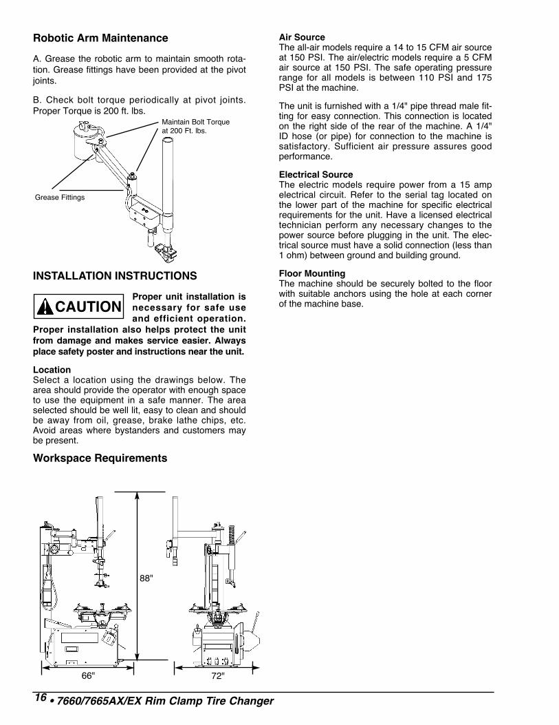
Robotic Arm Maintenance
A. Grease the robotic arm to maintain smooth rota-tion. Grease fittings have been provided at the pivotjoints.
B. Check bolt torque periodically at pivot joints.Proper Torque is 200 ft. lbs.
INSTALLATION INSTRUCTIONS
Proper unit installation isnecessary for safe useand efficient operation.
Proper installation also helps protect the unitfrom damage and makes service easier. Alwaysplace safety poster and instructions near the unit.
LocationSelect a location using the drawings below. Thearea should provide the operator with enough spaceto use the equipment in a safe manner. The areaselected should be well lit, easy to clean and shouldbe away from oil, grease, brake lathe chips, etc.Avoid areas where bystanders and customers maybe present.
Workspace Requirements
Air SourceThe all-air models require a 14 to 15 CFM air sourceat 150 PSI. The air/electric models require a 5 CFMair source at 150 PSI. The safe operating pressurerange for all models is between 110 PSI and 175PSI at the machine.
The unit is furnished with a 1/4" pipe thread male fit-ting for easy connection. This connection is locatedon the right side of the rear of the machine. A 1/4"ID hose (or pipe) for connection to the machine issatisfactory. Sufficient air pressure assures goodperformance.
Electrical SourceThe electric models require power from a 15 ampelectrical circuit. Refer to the serial tag located onthe lower part of the machine for specific electricalrequirements for the unit. Have a licensed electricaltechnician perform any necessary changes to thepower source before plugging in the unit. The elec-trical source must have a solid connection (less than1 ohm) between ground and building ground.
Floor MountingThe machine should be securely bolted to the floorwith suitable anchors using the hole at each cornerof the machine base.
16 • 7660/7665AX/EX Rim Clamp Tire Changer
88"
66" 72"
CAUTION
Maintain Bolt Torqueat 200 Ft. lbs.
Grease Fittings

77050/7055/7060/7065 X/EX Rim Clamp Tire Changer • 17

8183762 09/98 © Copyright 2001 Hennessy Industries and COATS® All Rights Reserved Printed in USA
FAILURE TO READ AND FOLLOW ALL WARN-
INGS AND INSTRUCTIONS IN THIS MANUAL
CAN LEAD TO SERIOUS PERSONAL INJURY OR
DEATH TO OPERATOR OR BYSTANDER.
THE OWNER IS RESPONSIBLE FOR MAINTAIN-ING THE OPERATION INSTRUCTIONS ANDDECALS FOR OPERATOR REFERENCE. FORADDITIONAL COPIES, CONTACT THE COATS®
COMPANY, 1601 J.P. HENNESSY DRIVE,LAVERGNE, TENNESSEE, 37086 - (800) 688-6359.
TIRE FAILURE UNDER PRESSURE IS HAZ-
ARDOUS! This tire changer Will Not Restrain
Exploding Tires, rims or other related equipment.
TIRES CAN EXPLODE, ESPECIALLY IF INFLATED
BEYOND SPECIFIED LIMITS. DO NOT EXCEED
TIRE MANUFACTURERS RECOMMENDED AIR
PRESSURE.
AN EXPLODING TIRE, RIM, OR BEAD SEATING
EQUIPMENT MAY PROPEL UPWARD AND OUT-
WARD WITH SUFFICIENT ENERGY TO CAUSE
SERIOUS INJURY OR DEATH TO OPERATOR
AND/OR BYSTANDERS.
DANGER
READ…Mounting and inflating thewrong size tire can getyou hurt. Read the size onthe tire and make sure itmatches the rim. Be espe-cially careful about puttinga smaller tire on a largerrim, such as a 16-inch tireon a 16.5-inch rim.
Inflation of a mismatchedtire and rim can cause anexplosion.
INSPECT…Before you put any tire ona rim, inspect the rim forrust, tough spots, bentedges, or cracks thatcould prevent the tire fromseating right. If you spotany of these problems,don’t mount the tire untilthe rim has been checkedby your shop foreman.
Inspect the tire for beaddamage.
MOUNT…Once you’ve made sure the tire is OKand the right size and the rim is OK,mount the tire safely. NEVER, everlean over the tire when you’re inflatingit. If a tire does explode, it will gostraight up. You don’t want to be overthe tire if that happens. Also, neverover-inflate the tire, even if the beaddoesn’t seat. Never inflate over 40PSI. If the tire hasn’t seated, some-thing is wrong. Deflate the tire andcheck it and the rim again. If it doesn’twork the second time, try another tire.
1. Damaged Beador Beads.
2. Rusty Wheels.(particularly in thebead seat area)3. Bent or
CrackedWheels.
4 A. Mismatched.(A mis-match of a 16-inch tire to a 16.5-inch rim causing anexplosion)4 B. Mismatched.(16.5-inch tire on a16-inch rim)
5. Walk-In Tireand Rim.
6. Back Injuries.
7. Hand or FingerInjuries.
(Hands or fingers tooclose to inflating tireor bead seats whichmay cause injury.)
8. Standing Clear.(Never put any part ofyour body over thetire changer duringinflation.)9. Beads will not
Seat at 40 PSI.
10. ImproperInflation.
Remember R.I.M. (Read, Inspect, Mount) for every tire.
BE CAREFUL OF THESE SITUATIONS:
ONE WORD FOR SAFETY
R.I.M.READ INSPECT MOUNT