7.62x51 mil manual
DESCRIPTION
7.62x51 Mil ManualTRANSCRIPT

UNCLASSIFIED
AD NUMBER
AD815788
NEW LIMITATION CHANGE
TOApproved for public release, distributionunlimited
FROMDistribution authorized to U.S. Gov't.agencies and their contractors;Administrative/Operational Use; MAR 1967.Other requests shall be referred toBallistic Research Laboratoriess, AberdeenProving Ground, MD 21005.
AUTHORITY
ARLS/CI, 23 Sep 2005
THIS PAGE IS UNCLASSIFIED
•? 0 MEMORANDUM REPORT NO. 1833
"UAERODYNAMIC CHARACTERISTICS OF
• OO THE 7.62 MM NATO AMMUNITION M-59, M-80, M-61, M-62
) • byME Maynard J. PiddO ngton
March 1967
This document is subject to special export controls and each transmittalto foreign governmnts or foreign nationals may be made only with priorapproval of Commanding Officer, U.S. Arw Ballistic Research Laboratories,Aberdeen Proving Ground, Maryland
BALLISTIC RESEARCH LABORATORIES 1967,
ABIERDEEN PROVINGGROUND,:MARYL.AN•

Destroy this report when it is no longer needed.Do not return it to the originator.
The findings in this report are not to be construed asan official Department of the Army position, unless I6o designated by other authorized documents.
a
BALLISTIC RESEARCH LABORATORIES
IMEMORANDUM REPORT NO. 1833
KAiRCHi ]967
AERODYNAMIC CHARACTERISTICS OF THE 7.62 MM NATO AMM41U-ITIOD1M-59, M-60, M-61, m-62
Maynard J. Piddington
Exterior Ballistics Laboratory
This document is subject to special export controls and each transmittalto foreign governments or foreign nationals aay be made only with priorapproval of Commanding Officer, U.S. Army Ballistic Research Laboratories,Aberdeen Proving Ground. Maryland
RDT&E Project No. IP0145CIA33DA3
ABERDEEN PROVING GROUND, MARYLANDj
__ I.. i

B LL T 3 I C R 1ESI RC W mAB0RAT0 TE
-BALLISTIC RESEARCH LABORATORIR T
!4E-F-ANDU7,i REPORT NO. 1833
Aberdeen Proving Ground, 114d.March 1967
AERODYNAP-,IC CHARACTERISTICS OF THE 7.62 ••VD NATO AIIUNIUiTIONi"1-59, -•SO, N-Cl, 1-62
UBS TRACT
Tests have been conducted in the Free-Flight Aerodynamic Range on
the NATO family of ammunition (14-80 ball, -- 59 bail, -1-62A-, aaid 1.-61
tracer). This report is the presentation and discussion of the data
obtained in these tests. in general, the projectiles exhibited adeauate
gyroscopic and dynamic stability in the regions of probable use. The
non-. racer members appear to have sufficiently similar drag properties to
be adequate ballistic matches, while the tracer is not a match beyond
about 600 meters.
i

TABLE OF COE[TEIifT
Page
. .STF CT ... . . . . . . . . . . . . . . . . . . .. . 3
LIST O SYU9OLS .. . . . . . . . . . . . . . . . . . . . 7
i. IPP ODUCTION . . . . . . . . . . . . . . . . . . . . . . . 9
TI. TEST . . . . . . . . . . . . . . . . . . . . . . . . . . . 9
I.. RESULTS . .. ........ ......................... 12
A. Drag . . . . . . . . . . . . . . . . . . . . . . . . 12
B. Stability .................... ..................... 21
C. lMagnus Moment Derivative ....... ............... ... 22
D. Normal Force Coefficient and Center of Pressure . 22
REFERENCES . . . . . .. . . . . . 2 3
APPEr{DIX .............................................. .
DISTRIBUTION LIST ................ .................... 3
I

ISST OF SYiMBOLS
*iwu'bod),y diaDreter uf Prcject le
q AnEgular velocity
X (Stal- 4ty factor)
C1
M 14ach T, uxmue r
barrel. twist
V Misi r eloc-ity
Drag Force
St+atic NMoentC', 0
-agnus Miloment
POi (1/2)PVWSS i CL
~ Damping MonentM M.
q a 1 /2)p V"ýS Z
Normnal ForceN OL(1/2)p V2 Sc
Anegative C + Cý, i ndicates 'hat the nmoment opposes tne argvlazr
veLoc-Lty and a positive C,, indictotes that the Magnus morment ic tr~jing to)
rotate the minssieles nose about the velocity vector in the direction of'
sp~n.
71
C:.
LIST OF SYMBOLS (Continued)
CPN Center of pressure of the normal force
I Axial moment of inertiax
I Transverse moment of inertiay
a Angle of attack
6 4Mean squared yaw
Reference length (k = d 0.308 inch)
Air density
8 f
zr.-.
I. INTRODUCTION
The adoption of the 7.62 rmm NATO infantry weapon series has led to
the introduction of a new family of sn~all arms proje2ti]es: the 1i-890
ball, the M-59 alternate ball, the ,I-b1 armor piercing, and the :M-62
tracer. In addition to their use in the infantry rifle, other apolications
"for the arumunition were proposed that involved more severe flight condi-
tions; for exmnrle, the U.S. Air Force proolcsed the ceveliorent of a
Gatling-type gun for use in light aircraft and for fighters of the
century class, and the U.S. ArrQi proposed several uses for helicopter
armrament. Frter evealuation of such uses required more aero.t.arrJie data
for the projectiles than had previously been octained. To fill t.is need,
the Air Proving Ground Center at the Eglin Air Force Base, Florida,recuested that the Ballizsic Research Laboratories (Bso) u deratae srark
range tests with the four tj+es of effb'Tunition. Applications of the1i**
data obtained have been reported. BRL enlarged the basic prograf, to
insure that adequate information was obtained tc evaluate a wide s nectrup
of uses.
II. TEST
The shapes of the four tyloes of projectiles are shown in Figure 1.
The shapes depicted are a synthesis obtained from consideration of
drawings cf the projectiles and frcom physical measurements of actual
unfired projectiles. 'C-ical physical properties are riven in Tna-e I.
The four projectiles have the same ogival nose, and all but the 1.1-62
tracer have similar boattailed afterbodies (the M-62 has a rounded base).
The alternate ball M-59 and the AP '.'-61 appear to be identical in general
exterior contour, while the ball V-80 is about one-half caliber shorter
Theis uas done tn coipliance witk 'IIPR NR-4-17, Project Nr. 5845.
Superscr-ic; nwr-bers denote references which may be found on rae 23.
A more accurate deternination of the physical dimensions should beobtained by measuring the projectiles after launch. To d0 this, theprojectile should be launched at standard velocity and then recoveredWithout dgaoe caused by the recovery system.
9

1. 259
05- - .767
'06
".308 -" -F/M- 59.297 3 0°
".326 - "
"--- 1.108 - -20•• 65 .767
3086
M-61.175
9 K .432 767
-- 1.322 -55
L•-rr
.389
Figur"e 1. Shapes and dimensions of I;ATO annmm~ition
1!32.05 - -- .71 -

[ tJ K -
I ....(I Y.� I
'--I '-1
-2 11-
C
4'0
K 2 2'p � --
-Ct V.> U> C.
* PJC> C> C> C>
'--I
(A C> U> Cuci ci (C.- 0-;
Ii .E21 -,
2 � �
H "¾
07'-4
-I-' C C> -i ccH �--C - �t; \j.-I I I I
- X �0
11

than the other two. All types have a knurled groove at about the same
distance from the nose tip and the M-61 has a second beveled groove aft
of the knurled one.
The projectiles were all tested in the BRL Aerodynamics Range. 3
The M-l4 rifle was used to launch the rounds at 2850 ft per sec (standard
muzzle velocity) and at velocities reduced to about 1200 ft per sec. The
M-80 firings were extended into the subsonic region. Higher than normal.
velocities were obtained by using a Mann barrel but the muzzle velocity
was limited to less than 3300 ft per sec because of extensive damage to
the projectile above this velocity.
4All data were computed in the usual manner and are given in
Table II; plots of these calculations are presented in the Appendix. It
is noted that the experimental data for the M-62 were obtained in the
same manner as for the other three types.
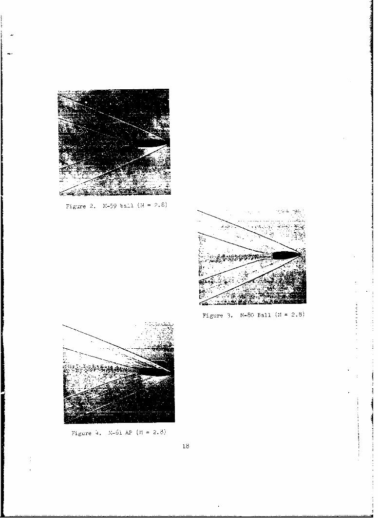
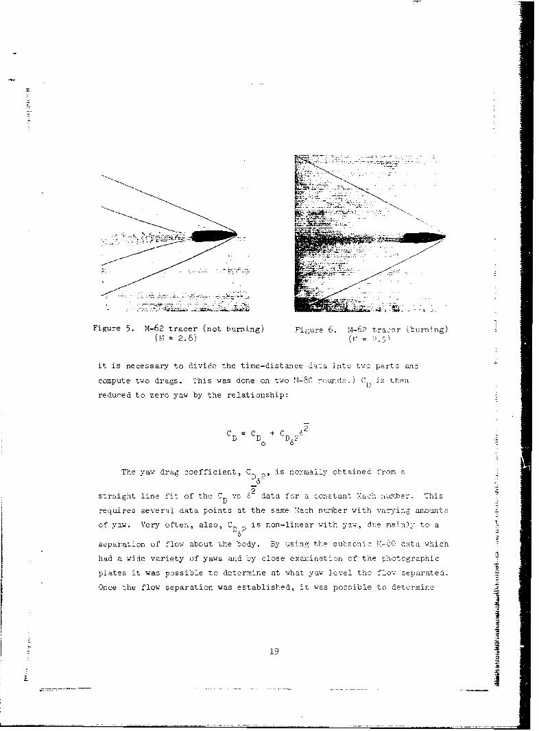
Photographs of each type of projectile are shown in Figures 2
through 6. Figures 5 and 6 are shadowgraph pictures of the inert M-62
and the M-62 with tracer respectively. The difference in the nature of
the flow in the area of the wake on the two pictures should be noted.
This difference in the wake flow accounts for the major decrease in drag
when the tracer is burning. A slight but undetermined drag decrease can
be attributed to the thrust of the tracer.
III. RESULTS
A. Drag
The drag force coefficient, C for each round is obtained by
fitting the time-distance data to a cubic equation by a least squares
process. (At about Mach one, where the drag is changing quite rapidly,
The normal twist of ,-14 rifles is 1 turn in 12 inches and for theMann barrel used it is 1 turn in 10 inches. A I in !2 inch tuqst gunmay aZllw a slightly higher velocity before projectile damage isexcessive.
12

iL s
-m_
Table IT. Sumjniry v-f Aercdynj-nic- 'ropertiec
'1-59
Range t f C0 C1. C1 + C H C.I CN CP sRd. (deg.) a q pa (inches
from base)
6549 2.785 4.5 .316 2.31 -5.6 .14 2.8 .760 2.19
6548 2.776 2.7 .300 2.36 -5.8 .13 2.5 .800 2.20
b462 2.410 2.2 .323 2.48 -6.1 .16 2.6 .803 1 .52
6463 2.393 3.2 .322 2.41 -6.0 .17 2.7 .786 1.47
6490 1.813 6.5 .425 2.50 -5.3 .10 3.5 .733 1.30
6884 1.797 3.4 .372 2.58 -5.0 .04 2.9 .787 1 .32
(881 1.795 5.8 .416 2.57 -6.3 .15 2.8 .798 1.34
6903 1.299 9.3 .536 2.67 -4.3 .04 2.8 .799 1.20
6901 1.267 6.9 .482 2.68 -3.0 -. 04 2.6 .326 1.16
6910 1.132 11.0 .596 2.72 -4.0 -. 02 2.7 .820 1.23
6907 1.131 10.9 .592 2.72 -2.8 -. 06 2.8 .808 1.18
i
13
__ _ _ _ _

Table II. Summary Of Aerodynamic Properties (Continued)
M -80
Range 1 CD CM CM + CM C M CN CP N sRd. (deg.) DL q & l (inches
from base)
6547 2.769 3.2 .297 1.74 -3.6 -. 08 2.5 .643 3.33
6546 2.744 4.0 .309 1.80 -3.6 -. 04 2.6 .641 3.30
6584 2.516 5.6 .350 1.80 -3.5 .04 2.7 .634 2.44
6583 2.464 5.2 .330 1 .77 -3.3 .03 2.8 .626 2.22
6158 2.448 .6 .290 1 .81 -2.8 -. 21 2.6 .647 2.08
6159 2.445 .6 .294 i.79 -4.5 -. 19 2.0 .712 2.14
6464 2.410 7.1 .390 1 .86 -3.6 .03 3.0 .626 2.35
6491 1.940 3.5 .370 1.94 -2.8 -. 08 2.8 .648 2.07
6492 1 .867 2.3 .356 1 .87 -3.6 -. 06 2.6 .649 2.00
6494 1.695 4.6 .408 1.95 -4.2 .08 2.8 .646 1.96
6493 1.615 3.1 .400 1.92 -4.9 .05 2.6 .658 1.91
6543 1.402 4.1 .439 1.97 -3.3 .01 2.7 .659 1.99
6542 1.378 4.6 .446 1.98 -2.9 -. 04 2.5 .673 1L89
6530 1.330 5.7 .470 2.04 -2.6 -. 03 2.6 .658 1.93
6529 1.295 3.6 .445 2.03 -2.2 -. 10 2.4 .689 1.88
6528 1.001 5.4 .476 2.11 -1.5 -. 09 2.4 .705 1.82
6528 .976 5.3 .394 -- -- -- -- - -
6528 .954 4.8 .314 2.44 3.0 .02 2.5 .737 1.70
6527 .946 6.7 .310 --...... ....
114

Table Hi. Sumnnari Of Aerodyalrn&i Properties (Continued)
Sr.I-80
Range M C 6 CI + CM CH Crl CP sRd. (deg.) D p a M (inches
from base)
6737 .637 5.7 .192 2.11 2.4 -. 30 1.91 ....
b738 .635 7.0 .210 2.14 - .4 -. 07 1.81 ....
6740 .606 10.1 .284 1.73 -- -- 2.36 ....
6739 .594 2.8 .144 2.13 - .8 -. 10 1.65 ..
6740 .585 14.2 .360 2.02 -- -- 2.08 ....
6735 .565 13.5 .364 2.05 2.6 -. 37 1.97 ....
6736 .529 8.0 .266 1.74 -- -- 2.18 ....
I7
-- : 15
' • i-fI

Table II. Summrary Of Aerodynajr ic Properties (Continued)
M-61
Range M CD C C + CM C C CP sRd. (deg.) P (inches
from base)
6553 2.788 3.3 .316 2.24 -5.4 .15 2.8 .757 2.36
6552 2.753 1.0 .293 2.24 -4.5 .09 2.2 .821 2.26
6460 2.520 7.8 .380 2.34 -5.3 .14 3.2 .732 1.50
6461 2.459 4.2 .340 2.45 -5.8 .14 2.7 .786 1 .42
6899 1 .817 8.6 .483 2.59 -5.4 .09 3.2 .754 1 .27
6882 1 .725 4.9 .412 2.48 -6.1 .16 2.9 .769 1 .35
6905 1.387 10.0 .553 2.62 -2.1 -. 01 3.1 .767 1.22
6902 1.309 11.7 .608 2.53 -4.0 .03 3.0 .762 1.30
I6i
I1
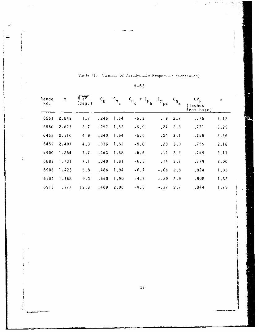
ThIne If. Suziarary Of Aerodynamic Proper-ties (Continued)
M -6 2
Range M CC CM C fI + , C e1 cpN
Rd. (deg .) O q &t a (inchesfrom base)
6551 2.849 1.7 .246 1.54 -6.2 .19 2.7 .776 3.12
6550 2.823 2.7 .252 1.52 -6.0 .24 2.8 .771 3.25
6458 2.510 4.9 .340 1.54 -6.0 .24 3.1 .755 2.26
6459 2.497 4.3 .336 1.52 -6.0 .20 3.0 .755 2.18
b900 1.854 7.7 .463 1.68 -6.6 .14 3.2 .769 2.11.
6883 1.731 7.1 .340 1.81 -6.5 .14 3.1 .779 2.00
6906 1.423 5.8 .486 1.94 -6.7 -. 06 2.8 .824 1.83
6904 1.368 9.3 .560 1.90 -4.5 -. 20 2.9 .808 1.82
6913 .917 12.8 .409 2.06 -4.6 -. 37 2.1 .844 1.79
II =I
I17i
ItI
F-igure 2.M-9bl(M=2)
Fig-ure 3. j.1-80 ball ('-2.8
Fiig-are £4. -~aPC 2.8)
-~ N
Figure 5. M-62 tracer (not burning) Figure 6.M2 tra:er (burning)04 = 2. 8) (
it is necessary to divide the time-distance data i atoc t wo parts and,
compute two dregs. This was dorne on two '4-8C ro-unds.) C P is Then
reduced to zero yaw by the relationship:
CL =C + C AD D D 20
The yaw drag coefficient, C i omlYotie rm-D 2' snral1bandfo
straiezht line fit of the C vs '1' data for a conztant V.ach number. ThI-isD
rea-aires several data cnoints at the same Mach number wit-h varying arioun ts:
of yaw. Very oft'en, also, C T) 2 is non-lin~ear with yaw, due ma~nly to a
separation of flow about the body. -By usinir the subsonic M-Qdata which
had a wide variety of yaws and by close exanination of the 7photog-raphic
plates it was possible to determirne at Twhat yaw llevel t.Ic flow separated.
Once the flow separation was established, it was possible to determnirýe
19
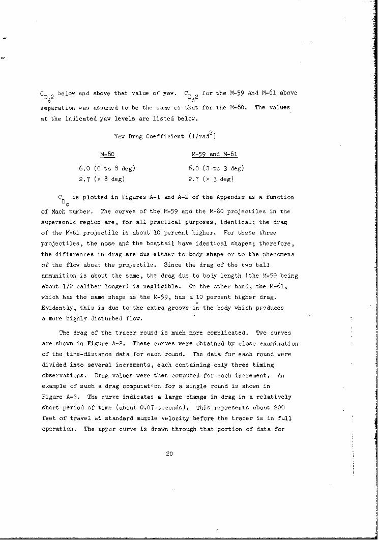
CD 2 below and above that value of yaw. CD 2 for the M-59 and M-61 above
separation was assumed to be the same as that for the M-80. The values
at the indicated yaw levels are listed below.
Yaw Drag Coefficient (i/rad2
M-80 M-59 and M-61
6.0 (0 to 8 deg) 6.0 (0 to 3 deg)
2.7 (> 8 deg) 2.7 (> 3 deg)
C is plotted in Figures A-1 and A-2 of the Appendix as a function
of Mach number. The curves of the M-59 and the M-80 projectiles in the
supersonic region are, for all practical purposes, identical; the drag
of the M-61 projectile is about 10 percent higher. For these three
projectiles, the nose and the boattail have identical shapes; therefore,
the differences in drag are due either to body shape or to the phenomena
of the flow about the projectile. Since the drag of the two ball
ammunition is about the same, the drag due to bo y length (the M-59 being
about 1/2 caliber longer) is negligible. On the other hand, the m-61,
which has the same shape as the M-59, has a 10 percent higher drag.
Evidently, this is due to the extra groove in the body which pyoduces
a more highly disturbed flow.
The drag of the tracer round is much more complicated. 'wc curves
are shown in Figure A-2. These curves were obtained by close examination
of the time-distance data for each round. The data for each round were
divided into several increments, each containing only three timing
observations. Drag values were then computed for each increment. An
example of such a drag computation for a single round is shown in
Figure A-3. The curve indicates a large change in drag in a relatively
short period of time (about 0.07 seconds). This represents about 200
feet of travel at standard muzzle velocity before the tracer is in full
operation. The upper curve is drawn through that portion of data for
20
each round represented by the ignition phase (non-burning). Using the
data at the end of the range for each round, the bottom curve is a good
approximation of the constant burning phase.
Caution should be exercised when computing the velocity his tory of
the M-62 projectile. A round launched at a velocity of about 2850 ft
per sec will initially have a drag which follows the upper curve in
Figure A-2. When the tracer begins to burn, however, (about 65 feet from
the gun) the drag drops very rapidly to the bottom curve where it remains
until the tracer has burned out. At this point (about 1 - 1/2 seconds
flight time), the drag jumps back to the upper curve where it will
remain throughout the remaining portion of its trajectory.
B. Stability
The overturning moment derivative, CM , and the sum of the dampinga
moment derivatives, C,, + C1 , are plotted versus Mach number in Figuresq a
A-h and A-5, respectively. 'cthing u-nusual is evident in these curves;
as one would expect, they have similar trends. An exception is the
possible dynamic instability of the M-80 in the subsonic region. It is
riot known whether this occurs for the other projectiles since they were
not launched subsonically.
Weak dynamic instability in the subsonic region would not present
a serious handicap to the flight characteristics of the M-80, or to the
other projectiles. By the time subsonic velocities are reached, the
projectile has already traveled about 800 meters and will have very
nearly zero yaw.- Consequently, considerable time (therefore, distance)
will be required before the yaw will have a chance to become large
enough to have a degrading influence on the flight behavior.
Values of the gyroscopic stability factor, s, were obtained for
each round and are plotted versus Mach number in Figure A-6. The high
values at about M = 2.8 were obtained by using a rifle with a 1 in 10
inch twist. These values have been converted to those that could be
expected from a rifle with a 1 turn in 12 inches by multiplying by the
ratio of the twists squared.
21
kIS- - - .----~- - - - - - ---~-
-- -- =------~~--= - __ ___------- -__ - - - ---- =--
Since the curves do not represent the in-fisght stability history
of the rounds, an example of such a history for the M-80 is shown in
Figure A-7. The curve represents a round launched at 2850 ft per sec.
The initial stability factor is 2.25 at 70°F; s increases throughout1h iniia stblt inrae thogh
its entire flight, but undergoes a change in its growth as the round
passes through Mach 1 due to a sudden drop in the drag. The curve
shows that the gyroscopic stability will never be worse than it is
immediately after launch.
C. Magnus Moment Derivative
The Magnus moment derivative, CM , is plotted versus Mach numberpa
in Figure A-8. All types behave roughly in the same manner. The shortest
round (M-80) has almost no moment, while the M-59 and M-61 (which differ
from the M-80 by body length only) have about the same values; these
values are both larger than those of the M1-80. The M-62 values are still
higher; this is probably due to the even longer body. The Magnus
moment for all four types goes negative at M = 1.5 or slightly less,
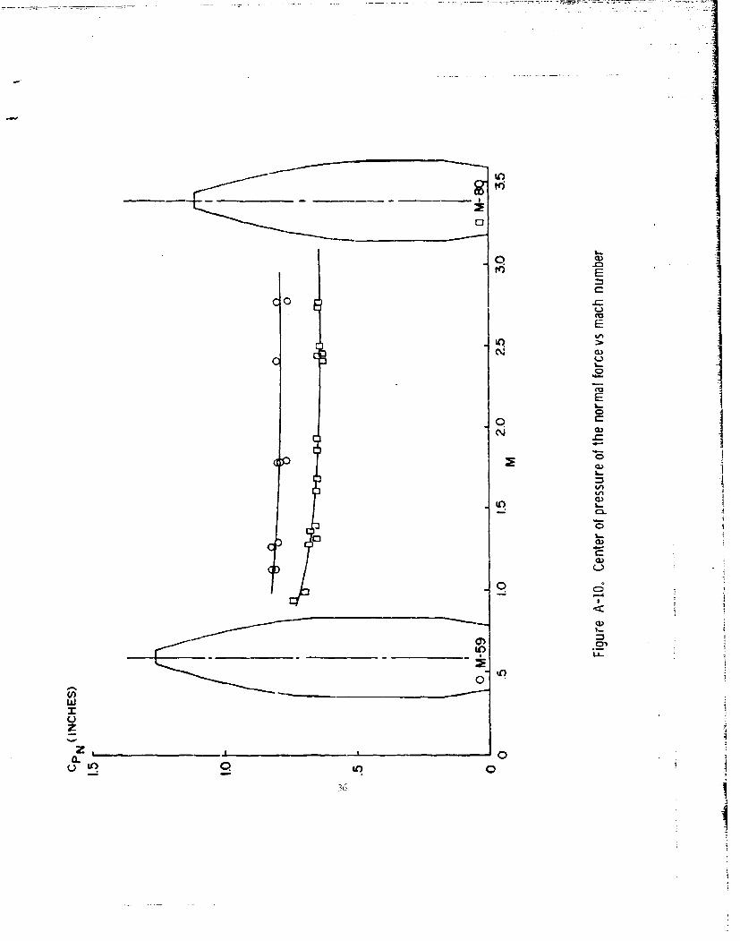
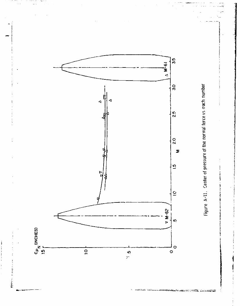
D. N•ormal Force Coefficient and Center of Pressure
The normal force coefficient, C , is plotted versus Mach numberN
in Figure A-9 and the center of pressure is given in Figures A-10 and
A-11. The cirves are well defined. The difference in drag between the
M-59 and the M-6- i again in evidnce in the difference in C N and C?
Also evident is the fact tnat the effect of the tracer burning on these
two terms is insignificant.
22
R~EIFERENCES
i. Kenneth Cobb. "Gun Settings for Side Firing Aircraft - 7.62Minigun•," JV, 65-2, July 1965.
2. Walter F. Braun, "The FrJ e Flight Aerydyna2iic CRnge," BallisticResearch Laboratories Retort No. 10148, July 1958.
3. Elizabeth R. Dickinson, "Physical Measurements of Projectiles,"Ballistic Research Laboratories Technical Note 874, February 195h.
4. Charles H. Murphy, "Free Flight Motion of Symmetric Missiles,"Ballistic Research Laboratories Report No. 22.1, July AS<
233
23
I-
- .~ -~

7.. .,. ,;7 • • • _ ,• • • • 7 -• C .. % 7 - .-. -- .
• •- ! •• , - •r i•,• •4-:• • "[ • :5•[7;}" " . • ' - •:- '" • -•.• •:••K• - _•-: • • -- • •-• • • ...
"p. . . I "t- • ": i [•
t•• -. , :
%j
I APPEN DI X
PLOTT•ED CURVES FOB EXPERIMENTAL DATA
i
525
*

C 0 M- 59(BALL)
.6
4
.3
.2
.1
0
M-80 (BALL).6
.5
.4
J.3
1.0 1.5 2.0 2.5 3.0M-
Figure A-i. Zero yaw drag coefficient vs mach numberIt _21
CD o M-61 (ARMOR PIERCING)
.3
5i
0~~ 0
M-62 (TRACER)
.6
.5 WITHOUT TRACER
.4
.2
.1 WITH TRACER
1.0 1.5 2.0 2.5 3.0M
Figure A-2. Zero yaw drag coefficient vs mach number28
C~I
cci
to 0
C~i
w~Ij -co Z
ir OD
m0
z W 00 0
z a.
tt) 0 L

CM0
2.8 -M- 59
2.6j
2.4
2.8 M -61
2.6
2.4
2.0 rM-62I 0
1.8 0
1.8
.6 1.0 1.5 2.0 2.5 3.0M
Figure A-4. Overturning moment derivative vs mach number30

CMq+ CMOj M- 590I
-6
-40
-20
0
-6
-4 0
-2
00
-26
M0.
000
I0
L- F0ueA5 apn~oetdrvtvsv ahnme31 c
6S M590 1 12 in. TWIST6 M59 1: 10 in. TWI.ST
2.........
0
6 M- 61
4
2 4Op 0--0
0
6 M-62
4
2
6 M- 80
4
01.0 1.5 2.0 2.5 3.0
M
Figure A-6. Stability factor vs mach number32
+ +
N
cLi,
.82
.84
ODI
clI
CMpa M-59
0
0 =ZIP
A 0
06 101.2.2.30
.2 ~M-s
Figure~0 A-8 anu moetdrvtvev ahnme03

CN M- 596
4o
0 -------
6 M-61
41
0 0
6 M- 62
4-V -- 0
2
0
.6 1.0 1.5 2.0 2.5 3.0M
Figure A-9. Normal force coefficient vs mach~ number35 _ _ _
I._.
o wE
C 0-
E
Inu
o
E
C.
N 00
CL)C3A
L-"
too
.1-'
u.I-
z
z, . 00.
02 It)
II
CQC
*1O
WN
w0
zI E
0 C
30-

Unclassified
Security classificstion
DOCUMENT CONTROL DATA- R & D(Socwai~y classification of ims,. body of abst,.oI an~d 1indexing annotatio., mIust be onferd when tha. o,...*1f tep.1 t. C1&8.ifJldj
I. OAIGINATtNG ACTIVITY (Cotporaf &uthof) 241. REPORT SECURITY CLASSIFICATION
U."). Army Da11istic PResrearch Laboratories Unc-lassifiedAlE~rdeen Proving Ground, Maryland2b MU
AMRPORY TITLE
AEPO0DYNAMI'_C CdHAACTERTSTICS OF THE 7.62 ~',-4 NATO Aý141UýITLCN M,-59, M.-90, 1-61, i~-62
4. DESCRIP TIV6 MOTCS (ni,.* ol report dand Ifel"iu.I dates)
s. Au TIORISI (First neims. middle M110,last. LadflSY)
Piddington, 'Mayniard J.
6. -EP'ORT DATE 75. TOT ýL NO. OF PAGES .N0PIlF
:cn i06?, 2i.CIZNTRACT OR :RANT NO. 04. ORICINATOR'S I5ý.PORT NUP"EIR(IS
b, PRO.JECT NO. FPf3T&E_ lP0145O 1A33D ~e~anunReport Lio. 1833
e. 9b. OTIIF. RZFOFIT NOISI (An.y odI., lnsaber MatmaybomeatSied
I0. DISTRISUTION *..AT9MENT
This documrent, is subj~ct to special export controls and each transmittal to foreig-ngovernments or foreign nationals may be made only with prior approval o'.' Cor~mmandingOfficer, U.S. Army Ballistic Research Laboratories, Aberdeen Proving Ground arElaand.
11. SUPPLEMENTARY N~OTES 12. SPONSORING MILITARV ACTIVITY{U.S. Army Materiel Crrommand
Wanhington, U.C.IA. ABSTRA,:T
Tests have been conducted in the Free-Fli ght Aerodynamic Range on the N~ATO faTn"ly ofammu-nition rM~ bal -,-5_.9 ball, M,-62AP, and 14'-61 tracer). Tis- report is the pre-sentation and discuission of the data obtained in these tests. In general, the pro-jecti les exhibited adeq~uate Q,'rcsccp1_c and dynanic st~ability in the rec-iorns of
probable use. The non-tracer members appear to have sufficiently similar drag proper-ties to be adequate ballistic matches, while tte tracer is niot a match bey"ond about600 meters.
DD IF10M0473 ::PLAC.KT o b:ftfw 1875.1AN4W Unclassif e
UnclassifiedSecurity Clegsificatlof -
ad. LINK A LINK 9 LINK CKEY WORDS- ---
ROLE WT ROLE T K OLE WT
NATO Ammunition
Exterior BallisticsAerodynamic Characteristics
Unclassi fiedSecuoimtyo C~laomssitaLen~o