714u3201 rev 06 - series iii interface handbook
DESCRIPTION
manualTRANSCRIPT


Instantel Inc.
International / Canadian Customers:
U.S.A. Customers:
Telephone: 1-613-592-4642 Toll free: 1-800-267-9111
Facsimile: 1-613-592-4296
Instantel Inc. 309 Legget Drive Ottawa, Ontario K2K 3A3 Canada
Instantel Inc. 808 Commerce Park Drive Ogdensburg, NY 13669 U.S.A. Website: www.instantel.com
Customer Support:
Instantel is represented by a network of qualified dealers throughout the United States, Canada, and Internationally. For further information, including product literature and the location of the dealer nearest you, contact Instantel.
• Extensive dealer network. • In–depth user documentation. • Comprehensive application support. • Technical support, 1–613–592–4642 or e-mail
© 1995-2004 Instantel Inc. All Rights Reserved Instantel, the Instantel logo, Blastmate, Blastware, Minimate and Minimate Plus
are either registered trademarks or trademarks of Instantel Inc. in the United States and/or other countries. 714U3201 Rev 06 - Printed in Canada, December 2004.

Series III Interface Handbook i
TABLE OF CONTENTS 1. Introduction 1–1
1.1 The Following Sensors and Cables Cannot be Used 1–1 1.2 Color Coding 1–1 1.3 Summary of Channel Connections 1–1
2. BlastMate III and MiniMate Plus 4 Channel Models 2–1 2.1 Connecting Series III Triaxial and Uniaxial Sensors 2–1
2.1.1 Materials Required 2–1 2.1.2 Connecting the Sensors 2–1
2.2 Connecting Series III Uniaxial Sensors 2–2 2.2.1 Materials Required 2–2 2.2.2 Connecting the Sensors 2–2
2.3 Connecting the Series III Standard Uniaxial Geophone 2–4 2.3.1 Materials Required 2–4 2.3.2 Connecting the Geophone 2–4
2.4 Connecting the OmniProbe High Frequency Geophone 2–5 2.4.1 Materials Required 2–5 2.4.2 Connecting the Geophones 2–5
3. BlastMate III and MiniMate Plus 8 Channel Models 3–1 3.1 Connecting Series III Uniaxial and Triaxial Sensors 3–1
3.1.1 Materials Required 3–1 3.1.2 Connecting the Sensors 3–1
3.2 Connecting Series III Uniaxial Sensors 3–2 3.2.1 Materials Required 3–2 3.2.2 Connecting the Sensors 3–2
3.3 Connecting the Series III Standard Uniaxial Geophone 3–4 3.3.1 Materials Required 3–4 3.3.2 Connecting the Geophones 3–4
3.4 Connecting the OmniProbe High Frequency Geophone 3–5 3.4.1 Materials Required 3–5 3.4.2 Connecting the Geophones 3–5
4. Connecting Other Sensor Types 4–1 4.1 Materials Required 4–1 4.2 Limits of Other Sensor Types 4–1 4.3 Connector Pinouts 4–2 4.4 Sensor Power from the Series III Monitor 4–2 4.5 Setting Sensor Sensitivity 4–2 4.6 An Example: Adapting a 14 Hz Geophone to a Series III Monitor 4–3
5. Series III Pin Outs 5–1
6. Notes 6–1

ii Series III Interface Handbook
Series III Interface Handbook 1–1
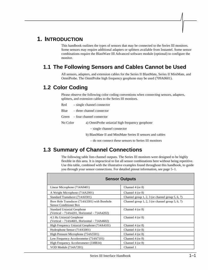
1. INTRODUCTION This handbook outlines the types of sensors that may be connected to the Series III monitors. Some sensors may require additional adapters or splitters available from Instantel. Some sensor combinations require the BlastWare III Advanced software module (optional) to configure the monitor.
1.1 The Following Sensors and Cables Cannot be Used All sensors, adapters, and extension cables for the Series II BlastMate, Series II MiniMate, and OmniProbe. The OmniProbe high frequency geophone may be used (709A0601).
1.2 Color Coding Please observe the following color coding conventions when connecting sensors, adapters, splitters, and extension cables to the Series III monitors.
Red – single channel connector
Blue – three channel connector
Green – four channel connector
No Color a) OmniProbe uniaxial high frequency geophone
– single channel connector
b) BlastMate II and MiniMate Series II sensors and cables
– do not connect these sensors to Series III monitors
1.3 Summary of Channel Connections The following table lists channel outputs. The Series III monitors were designed to be highly flexible in this area. It is impractical to list all sensor combinations here without being repetitive. Use this table, combined with the illustrative examples found throughout this handbook, to guide you through your sensor connections. For detailed pinout information, see page 5–1.
Sensor Outputs
Linear Microphone (714A0401) Channel 4 (or 8)
A Weight Microphone (714A2001) Channel 4 (or 8) Standard Transducer (714A0301) Channel group 1, 2, 3 (or channel group 5, 6, 7) Bore Hole Transducer (714A3301) with Borehole Sensor Conditioner Box
Channel group 1, 2, 3 (or channel group 5, 6, 7)
Standard Uniaxial Geophone (Vertical – 714A4201, Horizontal – 714A4202)
Channel 4 (or 8)
4.5 Hz Uniaxial Geophone (Vertical – 714A4601, Horizontal – 714A4602)
Channel 4 (or 8)
High Frequency Uniaxial Geophone (714A4101) Channel 4 (or 8) Hydrophone Sensor (714A5001) Channel 4 (or 8) High Pressure Microphone (714A5501) Channel 4 (or 8) Low Frequency Accelerometer (714A7101) Channel 4 (or 8) High Frequency Accelerometer (338B34) Channel 4 (or 8) VOD Module (714A7201) Channel 1

1–2 Series III Interface Handbook
Cable Interconnects
Uniaxial to Geo Adapter (714A5101) – converts uniaxial sensor readings from channel 4 to 1, or from channel 8 to 5.
Geo Conditioner Box (716A1901) – connects the standard uniaxial geophone (714A4201, 714A4202) to Channels 1, 2, 3 or 5, 6, 7.
Triax Uniax Splitter Cable (714A3901) – connects a triaxial sensor (channel group 1, 2, 3 or channel group 5, 6, 7) and a uniaxial sensor (channel 4 or 8).
Quad Splitter Cable (714A3201) – Connects uniaxial sensors to channels 1, 2, 3, 4, 5, 6, 7, and 8.
OmniProbe High Frequency Geophone to BlastMate III Attenuator (714A4001) – must be attached to the OmniProbe High Frequency Geophone in all connections.
Universal Breakout Box (716A2001) – used when connecting non standard sensors to any channel.
Channel 3(Channel 7)
Channel 2(Channel 6)
Channel 4(Channel 8)
Channel 1(Channel 5)
Connectors for signalconditioning
Channels 1, 2, 3 and 4(Channels 5, 6, 7 and 8)

Series III Interface Handbook 1–3
Monitor Inputs
MiniMate Plus MIC Channel 4 MiniMate Plus External MIC Channel 4 GEO Channels 1, 2, 3, and 4* (Tran, Vert, Long) BlastMate III MIC Channel 4 GEO Channel group 1, 2, 3, and 4 (Tran, Vert, Long) BlastMate III and MiniMate Plus 8 Channel
Ch 1–4 Channels 1, 2, 3, and 4 (Tran, Vert, Long, Mic)
Ch 5–8 Channels 5, 6, 7, and 8 (Tran2, Vert2, Long2, Mic2) *Note: On MiniMate Plus External models, do not connect both channel 4 inputs from the MIC connector
and the GEO connector at the same time.

1–4 Series III Interface Handbook
Notes:

Series III Interface Handbook 2–1
2. BLASTMATE III AND MINIMATE PLUS 4 CHANNEL MODELS
2.1 Connecting Series III Triaxial and Uniaxial Sensors The standard transducer (triaxial sensor) and microphone (uniaxial sensor) are the most commonly used Series III sensors for compliance monitoring.
2.1.1 Materials Required • BlastMate III 4 Channel or MiniMate Plus 4 Channel with internal geophones
• Series III Triaxial Sensor (e.g., Standard Transducer – 714A0301)
• Series III Uniaxial Sensor (e.g., L Microphone – 714A0401 or A Weight Microphone – 714A2001)
2.1.2 Connecting the Sensors Connect the sensors to the monitors according to the figure below. Attach the standard transducer (blue end) to the connector marked GEO on the BlastMate III. Attach the microphone (red end) to the connector marked MIC on both the BlastMate III and the MiniMate Plus.
MiniMate Plus Internal(4 Channel)
BlastMate III (4 Channel)
Figure 2-1 Connecting a Triaxial Sensor (e.g. Standard Transducer) and Uniaxial Sensor (e.g. Microphone) to 4 Channel Monitors.

2–2 Series III Interface Handbook
2.2 Connecting Series III Uniaxial Sensors Follow these instructions to connect Series III uniaxial sensors including the uniaxial 4.5 Hz geophone, high frequency uniaxial geophone, hydrophone sensor, linear microphone, or A weight microphone.
2.2.1 Materials Required • BlastMate III 4 Channel or MiniMate Plus 4 Channel for use with external sensors
• BlastWare III Software (Advanced Module required for the Series III High Frequency Uniaxial Geophone)
• Series III Quad Splitter Cable (714A3201)
• Series III Uniaxial Sensors (number and type as required)
2.2.2 Connecting the Sensors You can connect up to three uniaxial sensors to the Geo connector. If connecting two or three sensors, use the Quad Splitter Cable (714A3201). If connecting a single sensor, use the Uniaxial to Geo Adapter (714A5101).
Note: Series III uniaxial geophone sensors do not offer frequency compensation or Sensorcheck.
a) Multiple Sensors Connect the uniaxial sensors to the GEO connector on the monitor using the quad splitter cable as illustrated in figure 2-2. Attach the quad splitter cable (green end) to the connector marked GEO on either the BlastMate III or the MiniMate Plus. Connect one, two, or three Series III uniaxial sensors (red end) to channels 1 through 3 on the quad splitter cable. Channel 4 on the quad splitter cable is not required in this configuration.
b) Single Sensor Connect the uniaxial sensor to the GEO connector on the monitor using the Uniaxial to Geo Adapter cable. Attach the cable (blue end) to the connector marked GEO on either the BlastMate III or the MiniMate Plus. Connect a Series III uniaxial sensor (red end) to the red end of the cable.
Note: Under this configuration, analysis results appear in channel 1. Channels 2 and 3 do not operate in this configuration.

Series III Interface Handbook 2–3
Figure 2-2 Connecting Series III Uniaxial Sensors to 4 Channel Monitors.

2–4 Series III Interface Handbook
2.3 Connecting the Series III Standard Uniaxial Geophone
2.3.1 Materials Required • BlastMate III 4 Channel or MiniMate Plus 4 Channel for use with external sensors
• Series III Geo Conditioner Box (716A1901)
• Series III Standard Uniaxial Geophones (Vertical – 714A4201, Horizontal – 714A4202) number and type as required.
2.3.2 Connecting the Geophone Connect the Series III standard uniaxial geophones to the monitor using the geo conditioner box as illustrated in the figure below. Attach the geo conditioner box cable (blue end) to the connector marked GEO on either the BlastMate III or the MiniMate Plus. Connect one, two, or three Series III standard uniaxial geophones (red end) to channels 1 through 3 on the geo conditioner box.
Note: The geo conditioner box provides frequency compensation and Sensorcheck to the standard uniaxial geophones.
Figure 2-3 Connecting Series III Standard Uniaxial Geophones to 4 Channel Monitors.

Series III Interface Handbook 2–5
2.4 Connecting the OmniProbe High Frequency Geophone
2.4.1 Materials Required • BlastMate III 4 Channel or MiniMate Plus 4 Channel for use with external sensors
• BlastWare III Software (Advanced Module)
• Series III OmniProbe High Frequency Geophone to BlastMate III Attenuator (714A4001 - one for each OmniProbe High Frequency Geophone used)
• Series III Quad Splitter Cable (714A3201)
• OmniProbe High Frequency Geophone (709A0601 – number as required)
2.4.2 Connecting the Geophones Attach the OmniProbe high frequency geophone to BlastMate III attenuator to each OmniProbe high frequency geophone being used. Connect the other end of the attenuator to the quad splitter cable (red end) or the MIC connector on either the BlastMate III or the MiniMate Plus, as required. Attach the quad splitter cable (green end) to the GEO connector on the BlastMate III or the MiniMate Plus.
Note: OmniProbe high frequency geophones do not offer frequency compensation or Sensorcheck.
Figure 2-4 Connecting OmniProbe High Frequency Geophones to 4 Channel Monitors.

2–6 Series III Interface Handbook
Notes:

Series III Interface Handbook 3–1
3. BLASTMATE III AND MINIMATE PLUS 8 CHANNEL MODELS The following sections explain how to connect different sensors to the Series III monitors. All 8 channel monitors, other than the 8 channel compliance model, must be configured using the BlastWare III Advanced Module software.
3.1 Connecting Series III Uniaxial and Triaxial Sensors
3.1.1 Materials Required • BlastMate III (8 Channel) or MiniMate Plus (8 Channel)
• Series III Triax Uniax Splitter Cable (714A3901 – number as required)
• Series III Uniaxial Sensors (number and type as required)
• Series III Triaxial Sensors (number and type as required)
3.1.2 Connecting the Sensors Connect the uniaxial and triaxial sensors to the monitor using the triax uniax splitter cable as illustrated in the figure below. Attach the triax uniax splitter cable (green end) to the connectors marked channels 1 – 4 or channels 5 – 8 on either the BlastMate III or the MiniMate Plus. Connect a Series III uniaxial sensor (red end) to channels 4 or 8 on the triax uniax splitter cable (red end). Connect a Series III triaxial sensor (blue end) to channels 1 – 3 or channels 5 – 7 on the triax uniax splitter cable (blue end).
Figure 3-1 Connecting Series III Uniaxial and Triaxial Sensors to 8 Channel Monitors.

3–2 Series III Interface Handbook
3.2 Connecting Series III Uniaxial Sensors Follow these instructions to connect Series III uniaxial sensors including the uniaxial 4.5 Hz geophone, high frequency uniaxial geophone, hydrophone sensor, linear microphone, or A weight microphone.
3.2.1 Materials Required • BlastMate III (8 Channel) or MiniMate Plus (8 Channel)
• BlastWare III Software (Advanced Module)
• Quad Splitter Cables (714A3201 – number as required)
• Series III Uniaxial Sensors (number and type as required)
3.2.2 Connecting the Sensors You can connect up to eight uniaxial sensors to the monitor, one for each channel. If connecting two, three, or four sensors, use the Quad Splitter Cable (714A3201). If connecting a single sensor, use the Uniaxial to Geo Adapter (714A5101).
Note Series III uniaxial geophone sensors do not offer frequency compensation or Sensorcheck.
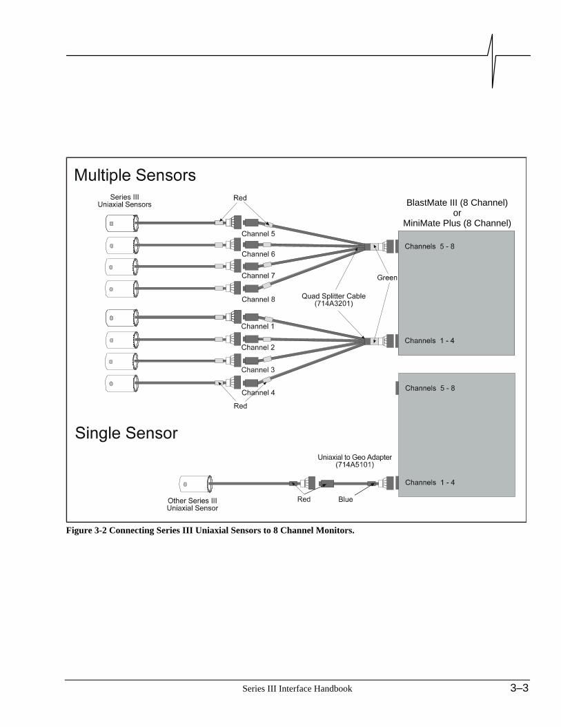
a) Multiple Sensors Connect the uniaxial sensors to the monitor using one or two quad splitter cables as illustrated in figure 3-2. Attach the quad splitter cables (green end) to the connectors marked channels 1 – 4 or channels 5 – 8 on either the BlastMate III or the MiniMate Plus. Connect the Series III uniaxial sensors (red end) to channels 1 through 8 on the quad splitter cable (red end), as required.
b) Single Sensor Attach the Uniaxial to Geo Adapter cable (blue end) to the connector marked channels 1 – 4 or channels 5 – 8 on either the BlastMate III or the MiniMate Plus. Connect a Series III uniaxial sensor (red end) to the red end of the cable.
Note: Depending upon the configuration, analysis results appear in channel 1 and/or channel 5. Channels 2, 3, 4, 6, 7, 8 do not operate in this configuration. Connecting Series III Uniaxial Sensors to 8 Channel Monitors.
Series III Interface Handbook 3–3
BlastMate III (8 Channel)or
MiniMate Plus (8 Channel)
Figure 3-2 Connecting Series III Uniaxial Sensors to 8 Channel Monitors.

3–4 Series III Interface Handbook
3.3 Connecting the Series III Standard Uniaxial Geophone
3.3.1 Materials Required • BlastMate III (8 Channel) or MiniMate Plus (8 Channel)
• Series III Geo Conditioner Box (716A1901)
• Series III Triax Uniax Splitter Cable (714A3901 – if four channel monitoring required)
• Series III Standard Uniaxial Geophones (Vertical – 714A4201, Horizontal – 714A4202) number and type as required.
3.3.2 Connecting the Geophones Connect the Series III standard uniaxial geophones to the monitor using the Series III geo conditioner box as illustrated in the figure below. Attach the conditioner cable (green end) to the connectors marked channels 1 – 4 or channels 5 – 8 on either the BlastMate III or the MiniMate Plus. Connect one, two, or three Series III standard uniaxial geophones (red end) to channels 1 through 3 on the conditioner (red end).
If you require four channel monitoring, connect the triax uniax splitter cable (714A3901) between the geo conditioner box and the monitor.
Figure 3–3 Connecting Series III Standard Uniaxial Geophones to 8 Channel Monitors.
Series III Interface Handbook 3–5
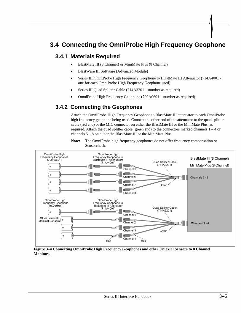
3.4 Connecting the OmniProbe High Frequency Geophone
3.4.1 Materials Required • BlastMate III (8 Channel) or MiniMate Plus (8 Channel)
• BlastWare III Software (Advanced Module)
• Series III OmniProbe High Frequency Geophone to BlastMate III Attenuator (714A4001 - one for each OmniProbe High Frequency Geophone used)
• Series III Quad Splitter Cable (714A3201 – number as required)
• OmniProbe High Frequency Geophone (709A0601 – number as required)
3.4.2 Connecting the Geophones Attach the OmniProbe High Frequency Geophone to BlastMate III attenuator to each OmniProbe high frequency geophone being used. Connect the other end of the attenuator to the quad splitter cable (red end) or the MIC connector on either the BlastMate III or the MiniMate Plus, as required. Attach the quad splitter cable (green end) to the connectors marked channels 1 – 4 or channels 5 – 8 on either the BlastMate III or the MiniMate Plus.
Note: The OmniProbe high frequency geophones do not offer frequency compensation or Sensorcheck.
Figure 3–4 Connecting OmniProbe High Frequency Geophones and other Uniaxial Sensors to 8 Channel Monitors.
3–6 Series III Interface Handbook
Notes:

Series III Interface Handbook 4–1
4. CONNECTING OTHER SENSOR TYPES A universal breakout box (716A2001) brings each pin from a four channel connector out to 5 way binding posts for attachment to non Instantel sensors. Resistive dividers, filter capacitors and other components can also be added to the terminals to tailor the sensor signal to the desired range and frequency response.
4.1 Materials Required • Series III Monitor
• BlastWare III Software (Advanced Module)
• Universal Breakout Box (716A2001)
• Other Sensor Types (number as required)
4.2 Limits of Other Sensor Types Other sensor types that may be used with the Series III monitors must provide the following:
1. Sensor signal must be limited to ±1.65 volts with respect to signal common, or 0 to 3.3 volts with respect to power ground.
2. Signal common is supplied by Series III monitors at 1.65 volts. The signal common sourcing and sinking current must not exceed 10 mA.
3. Switched 6V Battery supply ranges from approximately 7.2 volts to 5.5 volts. Total current from all sensors must not exceed 200 mA.
Green
Green
BlastMate III (8 Channel)or
MiniMate Plus (8 Channel)
Note: The Breakout Box has no internal physical connections
on the connection post. Figure 4-1 Connecting Other Sensor Types to the BlastMate III or the MiniMate Plus.
4–2 Series III Interface Handbook
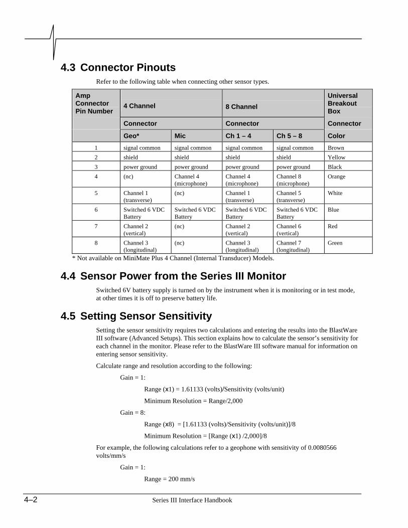
4.3 Connector Pinouts Refer to the following table when connecting other sensor types.
Amp Connector Pin Number
4 Channel
8 Channel Universal Breakout Box
Connector Connector Connector
Geo* Mic Ch 1 – 4 Ch 5 – 8 Color
1 signal common signal common signal common signal common Brown 2 shield shield shield shield Yellow 3 power ground power ground power ground power ground Black 4 (nc) Channel 4
(microphone) Channel 4 (microphone)
Channel 8 (microphone)
Orange
5 Channel 1 (transverse)
(nc) Channel 1 (transverse)
Channel 5 (transverse)
White
6 Switched 6 VDC Battery
Switched 6 VDC Battery
Switched 6 VDC Battery
Switched 6 VDC Battery
Blue
7 Channel 2 (vertical)
(nc) Channel 2 (vertical)
Channel 6 (vertical)
Red
8 Channel 3 (longitudinal)
(nc) Channel 3 (longitudinal)
Channel 7 (longitudinal)
Green
* Not available on MiniMate Plus 4 Channel (Internal Transducer) Models.
4.4 Sensor Power from the Series III Monitor Switched 6V battery supply is turned on by the instrument when it is monitoring or in test mode, at other times it is off to preserve battery life.
4.5 Setting Sensor Sensitivity Setting the sensor sensitivity requires two calculations and entering the results into the BlastWare III software (Advanced Setups). This section explains how to calculate the sensor’s sensitivity for each channel in the monitor. Please refer to the BlastWare III software manual for information on entering sensor sensitivity.
Calculate range and resolution according to the following:
Gain = 1:
Range (x1) = 1.61133 (volts)/Sensitivity (volts/unit)
Minimum Resolution = Range/2,000
Gain = 8:
Range (x8) = [1.61133 (volts)/Sensitivity (volts/unit)]/8
Minimum Resolution = [Range (x1) /2,000]/8
For example, the following calculations refer to a geophone with sensitivity of 0.0080566 volts/mm/s
Gain = 1:
Range = 200 mm/s

Series III Interface Handbook 4–3
Minimum Resolution = 0.1 mm/s
Gain = 8:
Range = 25 mm/s
Minimum Resolution = 0.0125 mm/s
4.6 An Example: Adapting a 14 Hz Geophone to a Series III Monitor
This example outlines the steps required to adapt a typical 14 Hz geophone to a Series III monitor. The steps involved and the calculations performed apply to all sensor types. If you have another sensor, follow these steps and perform the calculations to modify the sensor.
a) Schematic Drawing Refer to the following diagram throughout this example.
Warning: The following configuration does not provide filters to remove spurious responses at high frequencies outside the sensor’s frequency range.
Figure 4-2 Geophone Schematic.
Definitions:
Rc = Internal Coil Resistance
900 Ω for the 14 Hz geophone
Rs = External Shunt Resistor
This sets the desired damping for the geophone and affects the sensitivity
Rs = R1 + R2
This forms a resistive divider to attenuate to desired value for Series III input channel
Intrinsic Sensitivity
Open circuit output in volts of geophone for unit of velocity
0.042 V/mm/s for the 14 Hz geophone
b) Procedure Follow the steps outlined below to configure your sensor.
Step 1: Determine the Peak Velocity to be Measured

4–4 Series III Interface Handbook
What is the greatest peak velocity you need to measure. In this example, we will use 1,000 mm/s.
Step 2: Calculate the Peak Intrinsic Output from the Sensor at the Peak Velocity
Peak Intrinsic Output = Peak Velocity X 0.042 v/mm/s
= 42 Volts
Step 3: Choose the Desired Shunt Resistance from the Geophone’s Manufacturers Data
For this example, RS = 1,000 Ω for 0.73 damping.
Step 4: Calculate the Value of R1 and R2 to Attenuate the Peak Voltage
The maximum peak voltage for Series III monitors is 1.6113 Volts.
Desired Attenuation = 1.6113V
42V
= 0.03836
Therefore:
0.03836 = R2
Rc + Rs
∴ R2 = (0.03836)(Rc + Rs)
= (0.0384)(900 + 1000)
= 72.9 Ω (standard 1% = 73.2 Ω)
R1 = Rs - R2
= 1,000 - 72.9
= 927.1 Ω (standard 1% = 931 Ω)
Note: If the value of R2 is greater than the value of Rs, the damping is too extreme to allow the desired range. You must either reduce the damping or add additional gain externally.
Step 5: Modify the Geophone
Modify the 14 Hz geophone by adding the required resistors.
Figure 4-3 Adapting the 14 Hz Geophone.
Step 6: Start BlastWare III and Enter the Geophone’s Sensitivity
The sensitivity to enter into the Advanced Setups in the BlastWare III software:
Intrinsic Sensitivity X Attenuation = 0.042 V/mm/s X 0.03836
= 0.0016113 V/mm/s

Series III Interface Handbook 5–1
5. SERIES III PIN OUTS Pin
Number MiniMate Plus External,
BlastMate III (4 Channel)
MiniMate Plus, BlastMate III (8 Channel)
Geo Mic Ch 1 – 4 Ch 5 – 8
1 signal ground signal ground signal ground signal ground 2 shield shield shield shield 3 power ground power ground power ground power ground 4 (nc)* Channel 4
(microphone) Channel 4
(microphone) Channel 8
(microphone) 5 Channel 1
(transverse) (nc) Channel 1
(transverse) Channel 5
(transverse) 6 Switched 6 VDC
Battery Switched 6 VDC
Battery Switched 6 VDC
Battery Switched 6 VDC
Battery 7 Channel 2
(vertical) (nc) Channel 2
(vertical) Channel 6 (vertical)
8 Channel 3 (longitudinal)
(nc) Channel 3 (longitudinal)
Channel 7 (longitudinal)
*Channel 4 on MiniMate Plus External Models.
Pin Number
Linear Microphone (714A0401) A Weight
Microphone (714A2001)
Standard Transducer(714A0301)
Bore Hole Transducer(714A3301)
Standard Uniaxial
Geophone(714A4201, 714A4202)
4.5 Hz Uniaxial
Geophone (714A4601, 714A4602)
High Frequency
Uniaxial Geophone(714A4101)
Hydrophone Sensor
(714A5001)
1 signal ground signal ground signal ground signal ground signal ground signal ground signal ground 2 shield shield shield shield shield shield (nc) 3 power ground power ground power ground (nc) (nc) (nc) (nc) 4 Channel 4
(mic) (nc) (nc) signal
(Ch 4 or Ch 8)signal
(Ch 4 or Ch 8) signal
(Ch 4 or Ch 8)signal
(Ch 4 or Ch 8)5 (nc) Channel 1
(transverse) Channel 1
(transverse) (nc) (nc) (nc) (nc)
6 Switched 6 VDC Battery
Switched 6 VDC Battery
Switched 6 VDC Battery
(nc) (nc) (nc) (nc)
7 (nc) Channel 2 (vertical)
Channel 2 (vertical)
(nc) (nc) (nc) (nc)
8 (nc) Channel 3 (longitudinal)
Channel 3 (longitudinal)
(nc) (nc) (nc) (nc)

5–2 Series III Interface Handbook
Pin Number
High Pressure
Microphone (714A5501)
Low Level Accelero-
meter (714A7101)
High Frequency Accelero-
meter (338B34)
VOD Module
(714A7201)
1 signal ground signal ground signal ground signal ground 2 shield shield shield shield 3 power ground power ground power ground power ground 4 Channel 4
(mic) Channel 4 Channel 4 (nc)
5 (nc) (nc) (nc) Channel 1 6 Switched 6
VDC Battery Switched 6
VDC Battery Switched 6
VDC Battery Switched 6
VDC Battery 7 (nc) (nc) (nc) (nc) 8 (nc) (nc) (nc) (nc)
Series III Interface Handbook 6–1
6. NOTES

6–2 Series III Interface Handbook