7.-vpeg-software-input-output-functions.pdf
TRANSCRIPT

Yokogawa Engineering Asia – Singapore Training CentreAll rights reserved 2008

PT YOKOGAWA INDONESIATraining Center – Technical Support Group
PT YOKOGAWA INDONESIATraining Center – Technical Support Group Page.2

PT YOKOGAWA INDONESIATraining Center – Technical Support Group
PT YOKOGAWA INDONESIATraining Center – Technical Support Group Page.3
FCS - Configuration
PT YOKOGAWA INDONESIATraining Center – Technical Support Group
PT YOKOGAWA INDONESIATraining Center – Technical Support Group Page.4
FCS Constants
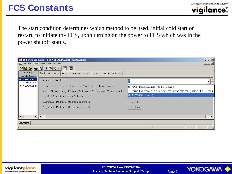
The start condition determines which method to be used, initial cold start or restart, to initiate the FCS, upon turning on the power to FCS which was in the power shutoff status.
PT YOKOGAWA INDONESIATraining Center – Technical Support Group
PT YOKOGAWA INDONESIATraining Center – Technical Support Group Page.5
Status of Function Block at Start Operation
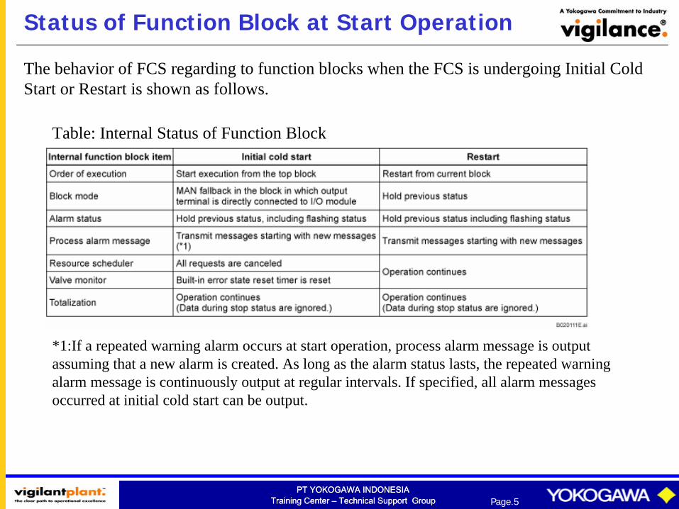
Table: Internal Status of Function Block
*1:If a repeated warning alarm occurs at start operation, process alarm message is output assuming that a new alarm is created. As long as the alarm status lasts, the repeated warning alarm message is continuously output at regular intervals. If specified, all alarm messages occurred at initial cold start can be output.
The behavior of FCS regarding to function blocks when the FCS is undergoing Initial Cold Start or Restart is shown as follows.
PT YOKOGAWA INDONESIATraining Center – Technical Support Group
PT YOKOGAWA INDONESIATraining Center – Technical Support Group Page.6
MAN Fallback of Function Block at Start Operation
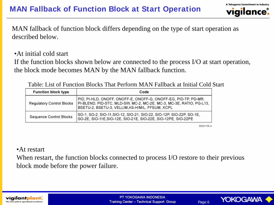
•At restart When restart, the function blocks connected to process I/O restore to their previous block mode before the power failure.
Table: List of Function Blocks That Perform MAN Fallback at Initial Cold Start
•At initial cold start If the function blocks shown below are connected to the process I/O at start operation, the block mode becomes MAN by the MAN fallback function.
MAN fallback of function block differs depending on the type of start operation as described below.
PT YOKOGAWA INDONESIATraining Center – Technical Support Group
PT YOKOGAWA INDONESIATraining Center – Technical Support Group Page.7
Status of Special Function Block at Start Operation
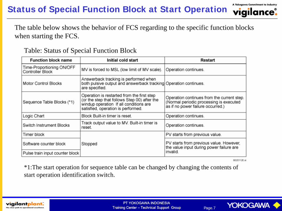
The table below shows the behavior of FCS regarding to the specific function blocks when starting the FCS.
Table: Status of Special Function Block
*1:The start operation for sequence table can be changed by changing the contents of start operation identification switch.
PT YOKOGAWA INDONESIATraining Center – Technical Support Group
PT YOKOGAWA INDONESIATraining Center – Technical Support Group Page.8
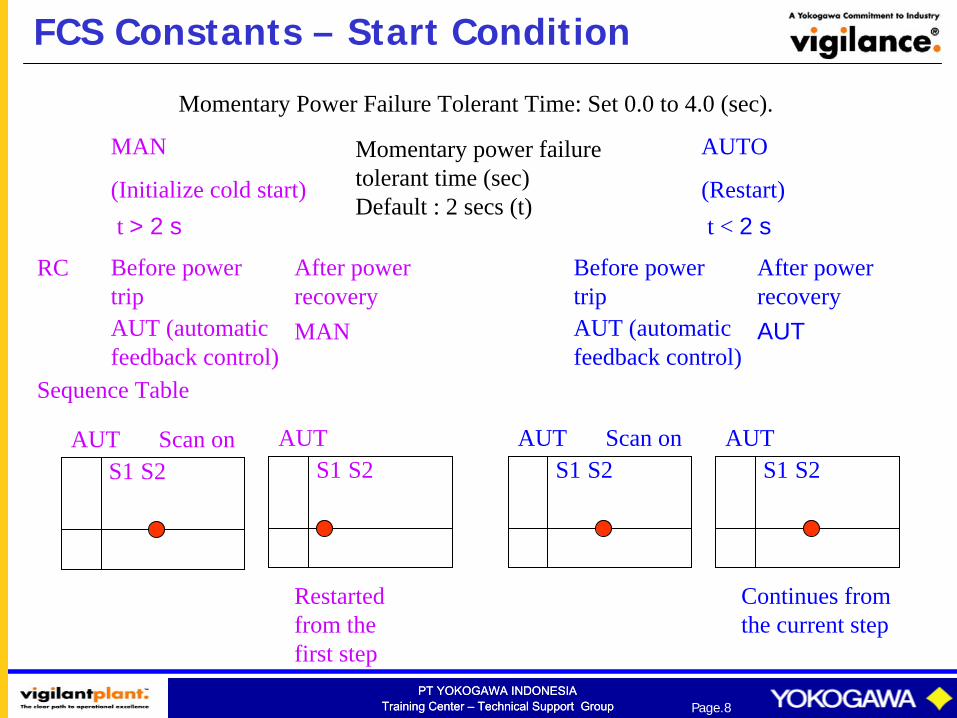
FCS Constants – Start Condition
MAN
(Initialize cold start)
AUTO
(Restart)
Momentary power failure tolerant time (sec) Default : 2 secs (t)
t > 2 s t < 2 s
MAN
After power recovery
AUT (automatic feedback control)
Before power trip
RC
Sequence Table
S1 S2AUT Scan on
Restarted from the first step
S1 S2AUT
AUT (automatic feedback control)
Before power trip
AUT
After power recovery
S1 S2AUT Scan on
Continues from the current step
S1 S2AUT
Momentary Power Failure Tolerant Time: Set 0.0 to 4.0 (sec).
PT YOKOGAWA INDONESIATraining Center – Technical Support Group
PT YOKOGAWA INDONESIATraining Center – Technical Support Group Page.9
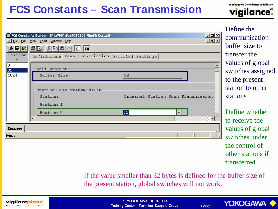
FCS Constants – Scan Transmission
Define the communication buffer size to transfer the values of global switches assigned to the present station to other stations.
Define whether to receive the values of global switches under the control of other stations if transferred.
If the value smaller than 32 bytes is defined for the buffer size of the present station, global switches will not work.

PT YOKOGAWA INDONESIATraining Center – Technical Support Group
PT YOKOGAWA INDONESIATraining Center – Technical Support Group Page.10
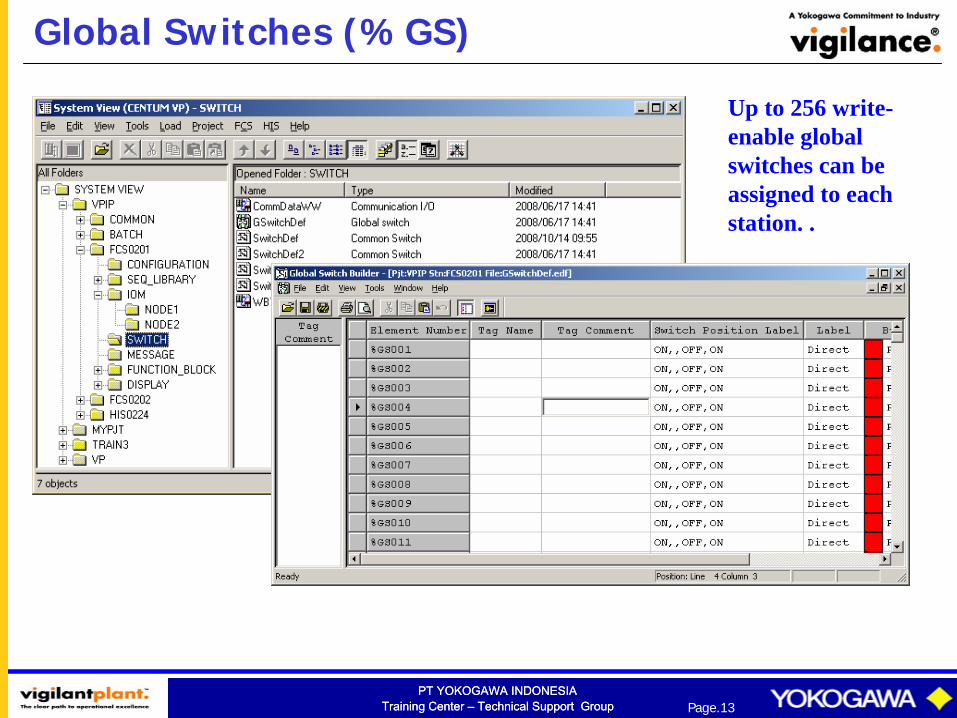
Global SwitchA global switch is an internal switch with the same logical value on all stations in the same domain.The value of global switch assigned to the present station can be checked and defined from any application on a station. Up to 256 write-enable global switches can be assigned to each station. The defined value is broadcasted to each station in the system via control bus scan transmission when data transfer to other stations is defined at Scan Transmission Definition on the FCS Constants Builder.When the values of global switches under the control of other stations are sent via scan transmission, the global switch on the present station is updated when data receipt is defined at Scan Transmission Definition on the FCS Constants Builder.The values of global switches are updated by 100 msec, which is fixed.
Figure: Global Switch
PT YOKOGAWA INDONESIATraining Center – Technical Support Group
PT YOKOGAWA INDONESIATraining Center – Technical Support Group Page.11
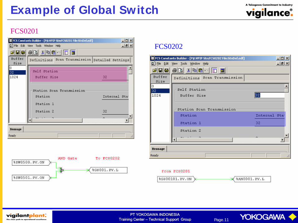
Example of Global Switch
FCS0201
FCS0202

PT YOKOGAWA INDONESIATraining Center – Technical Support Group
PT YOKOGAWA INDONESIATraining Center – Technical Support Group Page.12
Software Inputs/Outputs
Software inputs/outputs are virtual inputs/outputs that are provided by the FCS’s internal software.
Two types of software inputs/outputs are available: i) an “internal switch,” which is used to exchange logical values between function blocks or other application functions; and
ii) a “message output,” which is used to inform the occurrence of an event.
PT YOKOGAWA INDONESIATraining Center – Technical Support Group
PT YOKOGAWA INDONESIATraining Center – Technical Support Group Page.13
Global Switches (%GS)
Up to 256 write- enable global switches can be assigned to each station. .
PT YOKOGAWA INDONESIATraining Center – Technical Support Group
PT YOKOGAWA INDONESIATraining Center – Technical Support Group Page.14
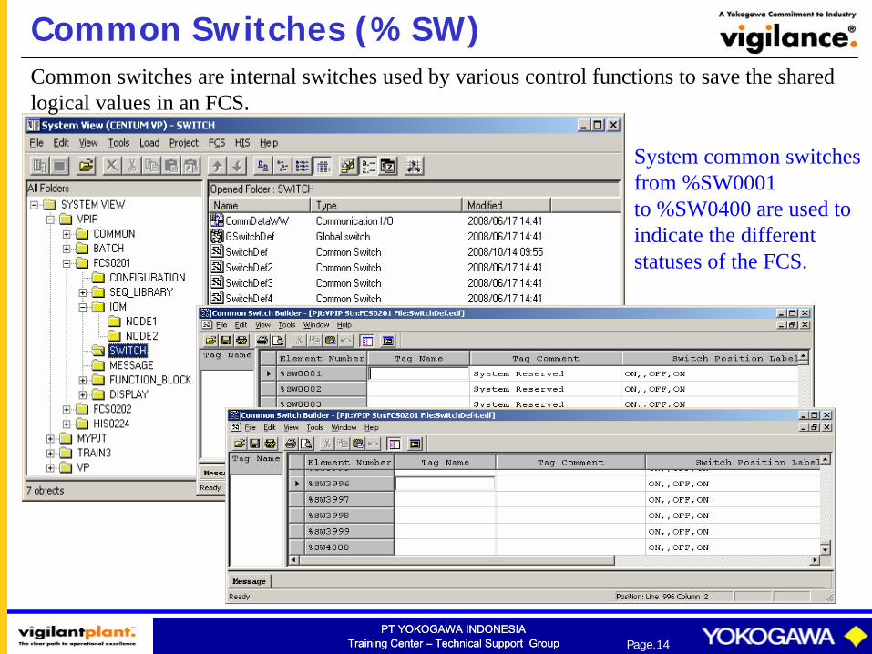
Common Switches (%SW)Common switches are internal switches used by various control functions to save the shared logical values in an FCS.
System common switches from %SW0001 to %SW0400 are used to indicate the different statuses of the FCS.

PT YOKOGAWA INDONESIATraining Center – Technical Support Group
PT YOKOGAWA INDONESIATraining Center – Technical Support Group Page.15
Annunciator Message (%AN)
Annunciator message is used to notify the operator of errors in the process.
Up to 24 alphanumeric characters are used.
1000 Annunciator Messages (FFCS-L)
PT YOKOGAWA INDONESIATraining Center – Technical Support Group
PT YOKOGAWA INDONESIATraining Center – Technical Support Group Page.16
Annunciator Message (%AN)
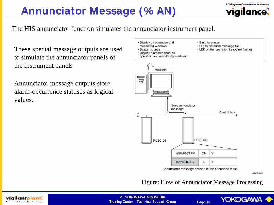
Annunciator message outputs store alarm-occurrence statuses as logical values.
The HIS annunciator function simulates the annunciator instrument panel.
These special message outputs are used to simulate the annunciator panels of the instrument panels
Figure: Flow of Annunciator Message Processing
PT YOKOGAWA INDONESIATraining Center – Technical Support Group
PT YOKOGAWA INDONESIATraining Center – Technical Support Group Page.17
Operator Guide Message (%OG)
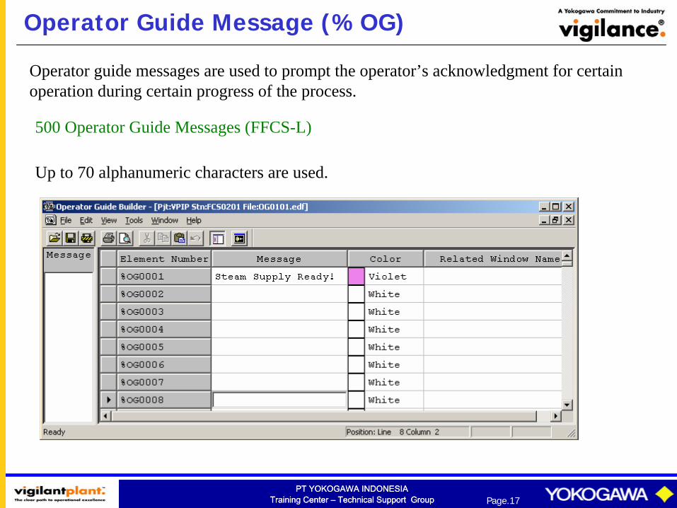
Operator guide messages are used to prompt the operator’s acknowledgment for certain operation during certain progress of the process.
500 Operator Guide Messages (FFCS-L)
Up to 70 alphanumeric characters are used.
PT YOKOGAWA INDONESIATraining Center – Technical Support Group
PT YOKOGAWA INDONESIATraining Center – Technical Support Group Page.18
Operator Guide Message (%OG)
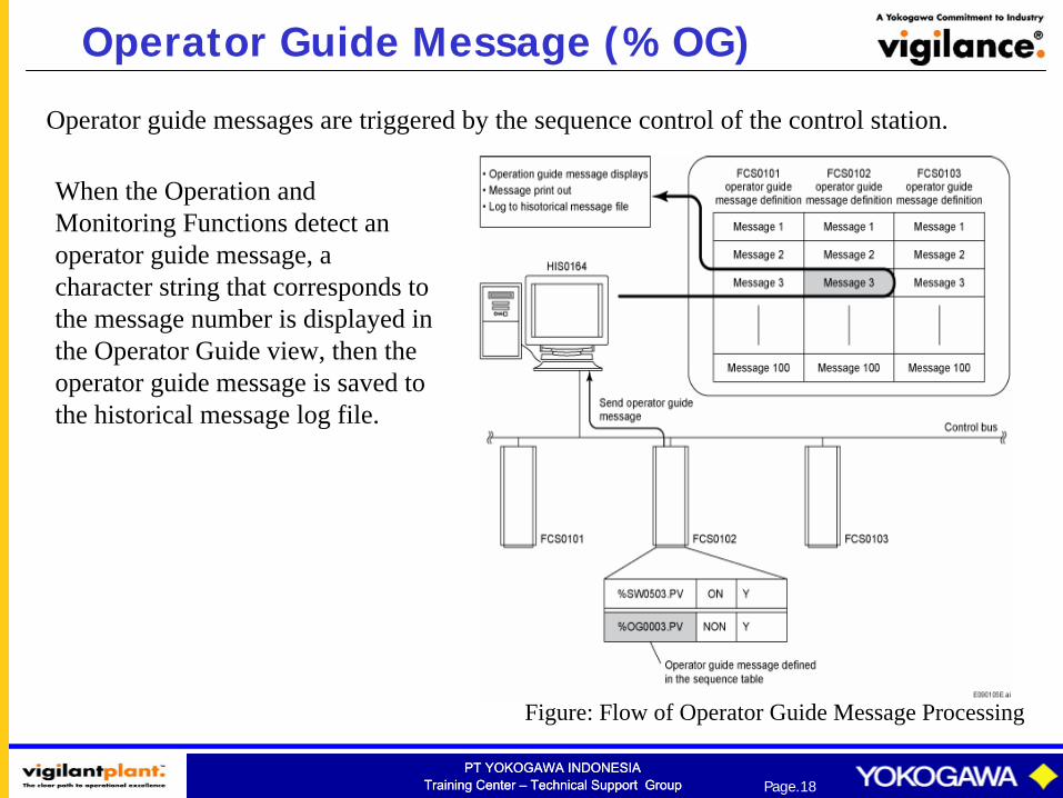
Operator guide messages are triggered by the sequence control of the control station.
When the Operation and Monitoring Functions detect an operator guide message, a character string that corresponds to the message number is displayed in the Operator Guide view, then the operator guide message is saved to the historical message log file.
Figure: Flow of Operator Guide Message Processing
PT YOKOGAWA INDONESIATraining Center – Technical Support Group
PT YOKOGAWA INDONESIATraining Center – Technical Support Group Page.19
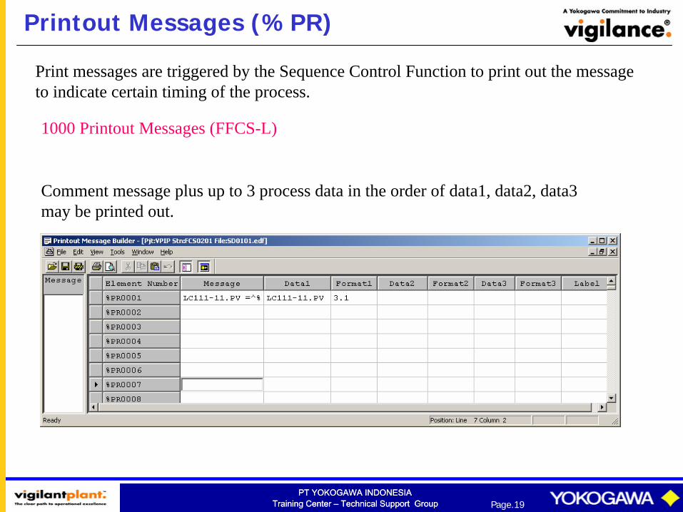
Printout Messages (%PR)
Print messages are triggered by the Sequence Control Function to print out the message to indicate certain timing of the process.
1000 Printout Messages (FFCS-L)
Comment message plus up to 3 process data in the order of data1, data2, data3 may be printed out.
PT YOKOGAWA INDONESIATraining Center – Technical Support Group
PT YOKOGAWA INDONESIATraining Center – Technical Support Group Page.20
Printout Messages (%PR)
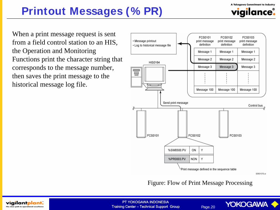
Figure: Flow of Print Message Processing
When a print message request is sent from a field control station to an HIS, the Operation and Monitoring Functions print the character string that corresponds to the message number, then saves the print message to the historical message log file.
PT YOKOGAWA INDONESIATraining Center – Technical Support Group
PT YOKOGAWA INDONESIATraining Center – Technical Support Group Page.21
Printout Messages (%PR)
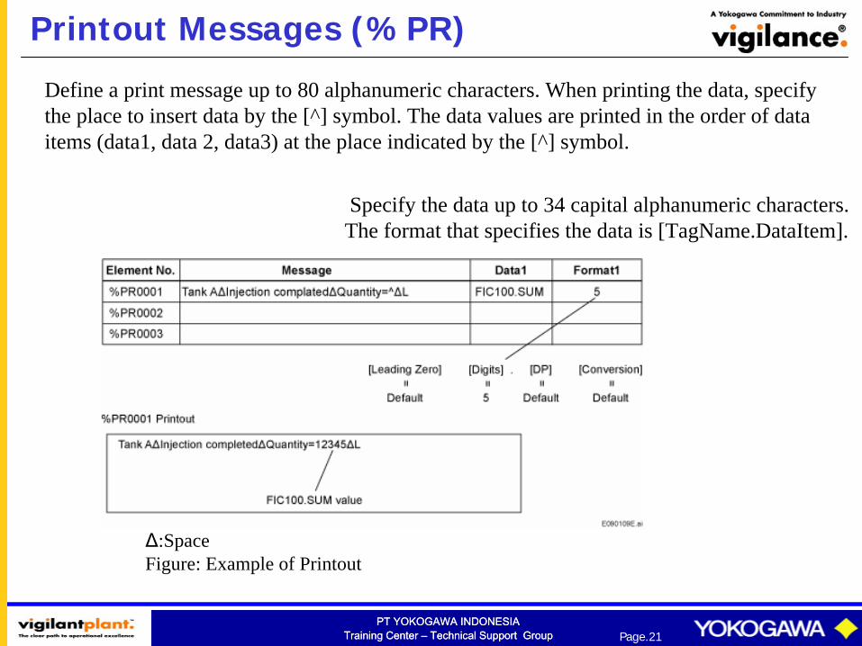
Define a print message up to 80 alphanumeric characters. When printing the data, specify the place to insert data by the [^] symbol. The data values are printed in the order of data items (data1, data 2, data3) at the place indicated by the [^] symbol.
Specify the data up to 34 capital alphanumeric characters.The format that specifies the data is [TagName.DataItem].
Δ:SpaceFigure: Example of Printout