7 vinyl chloride monomer process - universitas · pdf filedynamics and plantwide control. ......
TRANSCRIPT
Vinyl Chloride Monomer Process
201
Chemical Process Design: Computer-Aided Case Studies. Alexandre C. Dimian and Costin Sorin BildeaCopyright © 2008 WILEY-VCH Verlag GmbH & Co. KGaA, WeinheimISBN: 978-3-527-31403-4
7
7.1 Basis of Design
7.1.1 Problem Statement
Vinyl chloride monomer (VCM) is one of the leading chemicals used mainly for manufacturing polyvinyl chloride (PVC). The PVC worldwide production capacity in 2005 was of about 35 million tons per year, with an annual growth of about 3%, placed after polyolefi nes but before styrene polymers. In the 1990s the largest plant in the USA had a capacity of about 635 ktons [1] , but today there are several plants over one million tons. At this scale even incremental improvements in technology have a signifi cant economic impact. Computer simulation, process optimization and advanced computer - control techniques play a determinant role.
In the past the manufacture of VCM raised concerns regarding hazard, safety and pollution. Therefore, the VCM technology was among the fi rst to profi t from improvements suggested by process simulation. As result, the modern VCM plants are today among the cleanest and safest in the chemical process industries.
In this project the raw materials are ethylene and chlorine of high purity. The design refers to a capacity of 300 kton/year VCM polymerization grade. Informa-tion about technology used in this project can be found in encyclopaedic works [1 – 3] , review papers [4 – 6] , patents, as well as on the websites of leading producers. Table 7.1 shows quality specifi cations, namely regarding key impurities [2] .
The goal of this case study is to illustrate some generic issues raised by the conceptual design of a large - scale process involving several reaction and separation sections interconnected in a complex plant with recycles. The study emphasizes the intricate effects of handling the removal of numerous impurities generated in different reactors by a common separation system, with implications on process dynamics and plantwide control.

202 7 Vinyl Chloride Monomer Process
7.1.2 Health and Safety
Health and safety regulations (OSHA) require the monitoring of concentrations of harmful species in all facilities where VCM is produced or used. The employees should not be exposed to more than 1 ppm over 8 h, or no more than 5 ppm for periods exceeding 15 min. Chronic exposures to more than 100 ppm may lead to serious diseases. On the other hand, VCM is fl ammable by heat, fl ame and oxidiz-ing agents. Large fi res are diffi cult to extinguish. Because of possible peroxide formation, the VCM must be stored or transported under an inert atmosphere. The use of stabilizers prevents polymerization during processing and storage. VCM is generally transported in railroad tank cars and tank trucks.
7.1.3 Economic Indices
Table 7.2 presents some economic indices of a modern VCM technology [6] , in which stoichiometric values are indicated in parentheses. The yield for chlorine may rise over 98%, the yield for ethylene being slightly lower because of losses by combustion.
7.2 Reactions and Thermodynamics
7.2.1 Process Steps
Most of the VCM technologies are based on “ balanced ” processes. By this is meant that all intermediates and byproducts are recycled in a way that ensures a tight
Table 7.1 Purity specifi cations for vinyl chloride [2] .
Impurity Maximum level (ppm)
Acetylene 2 Acidity, as HCl by wt 0.5 Acetaldehyde 0 Alkalinity, as NaoH by wt. 0.3 Butadiene 6 1 - butene, 2 - butene 3, 0.5 Ethylene, propylene 4, 8 Ethylene, dichloride (EDC) 10 Nonvolatiles 150 Water 200 Iron, by wt. 0.25

7.2 Reactions and Thermodynamics 203
closure of the material balance to only VCM as the fi nal product, starting from ethylene, chlorine and oxygen. The main chemical steps are explained briefl y below.
1. Direct chlorination of ethylene to 1,2 - ethylenedichloride (EDC):
C H Cl C H Cl kJ/mol2 22 4 2 4 218+ → +
2. Thermal cracking (pyrolysis) of EDC to VCM:
C H Cl C H Cl HCl kJ/mol2 4 2 2 3 71→ + −
3. Recovery of HCl and oxychlorination of ethylene to EDC:
C H HCl O C H Cl H O kJ/mol2 4 2 2 4 2 22 0 5 238+ + → + +.
Hence, an ideal balanced process can be described by the overall equation:
C H Cl O C H Cl H O kJ/mol2 4 2 2 2 3 20 5 0 25 0 5 192 5+ + → + +. . . .
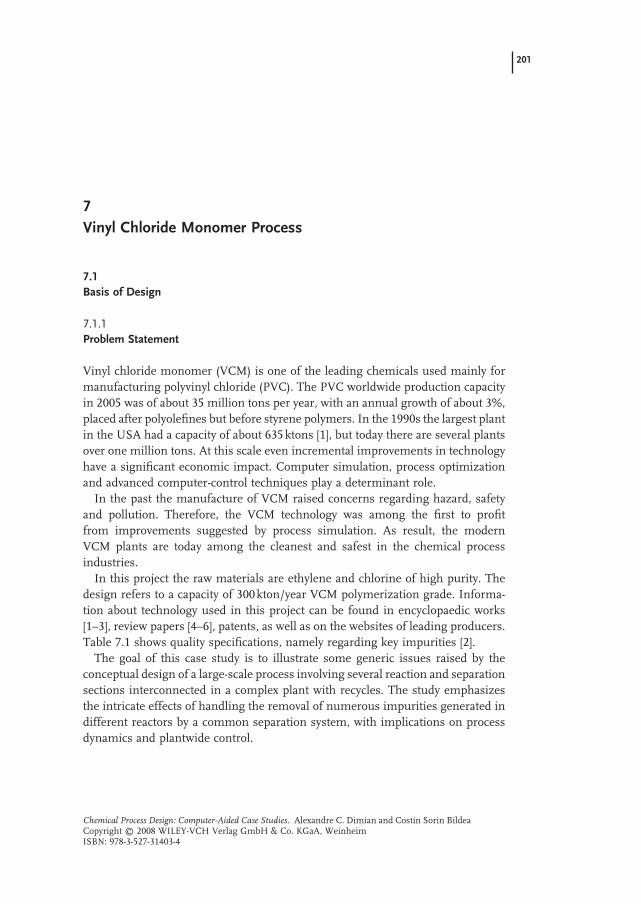
Therefore, half of the ethylene and the whole of the chlorine are fed to direct chlorination, while the other half of the ethylene goes to oxychlorination. The process block diagram consists of three plants, as shown in Figure 7.1 . Note that the purifi cation of all EDC streams produced by synthesis, as well as recycled, can be done in a common separation section. In order to increase the overall yield, the chlorine contained in subproducts, light or heavies, can be recovered by oxidation to HCl.
Since the overall reaction is very exothermal, the VCM plant should be able to cover a large part of its energy needs.
Most of the chlorinated waste is produced in the oxychlorination step. Therefore, employing only direct chlorination of ethylene is more benefi cial from the envi-
Table 7.2 Economic indices of VCM processes [6] .
Raw material (kg/t VCM) • ethylene 462 (448) • chlorine 578 – 585 (568) • oxygen 131 – 139 (128)
Utility/t VCM • electric power (kWh) 105 – 110 • steam (t) 0.05 – 0.20 • cooling water (m 3 ) 150 – 175 • fuel (Mcal) 660 – 700 Operators (men/shift) 4
204 7 Vinyl Chloride Monomer Process
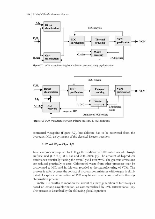
ronmental viewpoint (Figure 7.2 ), but chlorine has to be recovered from the byproduct HCl, as by means of the classical Deacon reaction:
2 0 5 2 2 2HCl O Cl H O+ → +.
In a new process proposed by Kellogg the oxidation of HCl makes use of nitrosyl - sulfuric acid (HNSO 5 ) at 4 bar and 260 – 320 ° C [9] . The amount of byproducts diminishes drastically raising the overall yield over 98%. The gaseous emissions are reduced practically to zero. Chlorinated waste from other processes may be incinerated to HCl, and in this way recycled to the manufacturing of VCM. The process is safer because the contact of hydrocarbon mixtures with oxygen is elimi-nated. A capital cost reduction of 15% may be estimated compared with the oxy-chlorination process.
Finally, it is worthy to mention the advent of a new generation of technologies based on ethane oxychlorination, as commercialized by EVC International [10] . The process is described by the following global equation:
Figure 7.1 VCM manufacturing by a balanced process using oxyclorination.
Figure 7.2 VCM manufacturing with chlorine recovery by HCl oxidation.

2 3 2 32 6 2 3 2C H Cl O C H Cl H O2 2+ + → +/
The technology profi ts from the extensive experience gained by the oxychlorination of ethylene, but is based on a completely different catalyst. The new process claims a cost reduction of about 30%, because the ethane price is about one third that of ethylene.
7.2.2 Physical Properties
Table 7.3 displays key physical properties of the main components. Large differ-ences in the physical state may be observed. Ethylene and HCl are gases, chlorine and VCM may be handled as liquids at lower temperatures and adequate pressure, while ethylene - dichloride is a liquid. Therefore, the use of higher pressures and lower temperatures is expected in various processing steps.
At this stage, it is interesting to examine the properties of all chemical species, products, byproducts, intermediates and impurities with impact on the process design. Table 7.4 gives a list of normal boiling points, as well as origin and exit points. This issue will be clearer after presenting the chemistry of each reaction step. It may be seen that traces of acetylene will follow HCl in recycle. Since some chlorinated species have boiling points close to EDC, its purifi cation will be demanding.
Table 7.3 Physical properties of the main components.
Name Ethylene Chlorine HCl VCM EDC
Molecular formula C 2 H 4 Cl 2 HCl C 2 H 3 Cl C 2 H 2 Cl 2 Molecular weight 28.05 70.906 36.46 62.5 98.96 Normal boiling point, ° C − 103.8 − 34.5 − 85.1 − 13.4 83.4 Critical temperature, K 282.4 417 324.6 429.7 561 Critical pressure, bar 50.4 77 83.1 56 53.7 Critical volume, cm 3 /mol 129 124 81 169 220 Liquid density, kg/m 3 ( ° C) 577 ( − 110) 1563 ( − 34) 1193 ( − 85) 969 ( − 14) 1250 (16) ∆ H vap at nbp, kJ/mol 13.553 20.432 16.161 20.641 32.029 Explosion limit in air, % 2 – 36 None None 4 – 22 6 – 16
7.3 Chemical-Reaction Analysis 205
7.3 Chemical - Reaction Analysis
A key aspect in the VCM technology is the removal of numerous byproducts and impurities formed in the three reaction systems. By passing through intercon-nected recycles some impurities produced in one reactor may induce the forma-tion of impurities in other reactors. For example, impurities generated by the EDC

206 7 Vinyl Chloride Monomer Process
cracking but not removed from HCl will generate other impurities in oxychlorina-tion, which in turn, if not removed by EDC purifi cation, will deteriorate the selec-tivity of the cracking and direct chlorination steps, accumulating even more impurities in recycles, etc . Hence, the handling of impurities is the key issue in managing the overall plant material balance by VCM manufacturing. Because of simulation constraints, namely in dynamic mode, the number of components involved in the chemistry of different steps should be limited. However, in order to get consistent material balance it is preferable to use stoichiometric equations and avoid mass - yield expressions.
7.3.1 Direct Chlorination
The direct chlorination of ethylene consists of reaction between dissolved gaseous reactants in the liquid EDC following the equation:
C H Cl C H Cl kJ/mol2 2 44 2 2 2980 218+ → = −∆H (1)
The catalyst is of Lewis - acid type, in most cases FeCl 3 , in concentrations of 0.1 to 0.5 wt%. Secondary reactions take place. The most important byproduct is the 1,1,2 - trichlorethane (TCE), as described by:
C H 2Cl C H Cl HCl32 4 2 2 3+ → + (2)
Table 7.4 Chemical species in VCM process.
Component Formula Nbp, ( ° C) Origin Exit
C2H2 C 2 H 2 – 84.0 CK VCM separation, sent to selective hydrogenation
HCl HCl – 66.5 CK VCM separation, to Oxy MECL CH 3 Cl – 24.0 CK, Oxy VCM purifi cation VCM C 2 H 3 Cl – 13.8 CK VCM separation, product BUTD C 4 H 6 – 4.5 CK EDC purifi cation, lights ETCL C 2 H 5 Cl 12.3 DC, CK, Oxy EDC purifi cation, lights CLP C 4 H 5 Cl 37.0 CK EDC purifi cation, lights DCM CH 2 Cl 2 40.7 CK, Oxy EDC purifi cation, lights DCE = C 2 H 2 Cl 2 47.7 CK, Oxy EDC, purifi cation lights TCM CHCl 3 61.3 CK, Oxy EDC purifi cation, lights CCl4 CCl 4 76.7 CK, Oxy EDC purifi cation, lights EDC 1,2 - C 2 H 4 Cl 2 82.4 DC, Oxy Intermediate, to CK TRI C 2 HCl 3 86.7 CK, Oxy EDC purifi cation CLAL C 2 H 3 Cl 3 97.7 Oxy Separating Oxy TCE C 2 H 3 Cl 3 113.9 DC, CK, Oxy EDC purifi cation, heavies Heavies C 4 H 8 Cl 2 155.1 CK, Oxy EDC purifi cation
DC: direct chlorination; CK: cracking; Oxy: oxychlorination

Very likely is the chlorination of EDC to trichloroethane (TRE):
C H Cl Cl C H Cl TCE HCl2 32 4 2 2 3+ → ( )+ (3)
The formation of impurities involves the occurrence of radicals. For this reason small amounts of oxygen, often present in the chlorine produced by electrolysis, may increase the selectivity to EDC by inhibiting the secondary reactions.
The use of high - purity reactants is recommended to avoid the formation of a larger spectrum of impurities that might complicate even more the EDC purifi ca-tion. Slight excess of chlorine is preferred in order to ensure complete ethylene conversion.
The direct chlorination of ethylene may be conducted following two tech-niques:
1. Low - temperature chlorination (LTC). 2. High - temperature chlorination (HTC).
In LTC the reactor is a simple gas – liquid contact column operating at tempera-tures between 50 – 70 ° C, below the mixture boiling point (Figure 7.3 a). Lower temperature is advantageous for achieving higher selectivity, over 99%. Two methods can be used for removing the heat of reaction, such as an internal heat - transfer device, for example a cooling coil, or external heat exchanger with recy-cling of cold EDC. As a disadvantage we note that rejecting the heat of reaction to the environment at low temperature is highly ineffi cient. Another major draw-back is the catalyst removal from EDC by costly operations and sources of pollution.
Figure 7.3 Reaction techniques for the direct chlorination of ethylene.
7.3 Chemical-Reaction Analysis 207

208 7 Vinyl Chloride Monomer Process
In HTC, the reaction is conducted at the boiling point of EDC at 1.5 to 5 bar and 90 to 150 ° C. In this manner the heat of reaction, which is seven times the heat of EDC vaporization, can be used advantageously for purifi cation. The chemi-cal reactor may be integrated as a reboiler of a distillation column, or designed as independent equipment (Figure 7.3 b). A disadvantage of HTC would be lower selectivity, but some patents claim that modifi ed catalysts and/or the use of inhibi-tors make possible operation up to 150 ° C.
The overall process rate involves the addition of resistances for mass transfer and chemical reaction. With respect to chemical rate, Orejas [11] proposes the following equations obtained by the regression of industrial data:
− = = − − −r k c c k T13 1 1
2 2 11493 2156 58D1 C H Cl D12 with exp m mol s( . / ) (7.1)
− = = × − −r k c c k T1 22 9 6 2
2 2 8 517 10 7282 21D C H Cl D22 with exp m kmol s. ( . / ) −−1 (7.2)
At 60 ° C the reaction rate constants are 17.7 and 2.71, in the above units. These data are in good agreement with experimental values of 13.2 and 2.39 [12] .
7.3.2 Oxychlorination
The oxychlorination step is described by the following global reaction:
C H HCl O C H Cl H O kJ/mol22 4 2 2 4 2 29802 0 5 295+ + = + = −. ∆H (4)
The catalyst widely used is based on copper(II) chloride impregnated on alumina. The highly exothermal reaction is carried out at temperatures around 200 ° C and pressures of 1.5 – 5 bar, in fi xed - bed or fl uid - bed reactors. The fl uid - bed technique offers more intensive heat transfer, prevents the occurrence of hot spots and allows more effi cient catalyst regeneration. Ethylene conversion of 93 – 97% can be achieved with selectivity in EDC of 91 – 96%.
As mentioned, the spectrum and amount of impurities formed during oxychlo-rination is much larger compared with direct chlorination. Some key impurities are listed below: 1,1,2 - trichloroethane (TCE), chloral (CCl 3 - CHO), trichloroethyl-ene (TRI), 1,1 - and 1,2 - dichloroethylenes, ethyl chloride, chloro - methanes (methyl - chloride, methylen - chloride, chloroform), as well as polychlorinated high - boiling components. In particular, chloral needs to be removed immediately after reaction by washing because of its tendency to polymerization.
The formation of TRI is undesired, because its removal by distillation is very diffi cult. In fact, TRI and EDC form a low - boiling point azeotrope very close to EDC. The formation of TRI in the oxychlorination reactor is due to the acetylene entrained with the HCl byproduct from cracking. Two solutions can be adopted:
• selective catalytic hydrogenation of acetylene in the HCl recycle stream; • chlorination of TRI to heavies after concentration by EDC distillation.

Some processes make use of the fi rst method. The second one has been high-lighted by studies in the fi eld of process dynamics and plantwide control [7, 8] . More generally, the chemical conversion of impurities is a powerful method for diminishing positive feedback effects through recycles with negative infl uence on operation and control.
Secondary reactions manifest, as explained next. An amount of ethylene is lost by combustion at higher temperature:
C H O Cl H O22 4 2 2+ = + (5)
Small amounts of chlorine appear since the copper catalyst is active for oxidation:
HCl O Cl H O+ = +0 5 2 2 2. (6)
Chlorine is involved further in radical reactions producing many chlorinated species. At higher temperature even the C – C bond in chlorinated products can break, forming chloromethanes. All these reactions lead fi nally to a wide spectrum of impurities. Stoichiometric equations are given below and may be used for material - balance purposes, although the true reaction mechanism is much more complex:
C H Cl Cl C H Cl TCE HCl2 4 2 2 2 3 3+ = +( ) (7)
C H Cl C HCl TRI HCl2 2 32 22+ = +( ) (8)
C H Cl O Cl C CHO CLAL HCl H O4 22 2 3 22+ + = − ( ) + + (9)
C H Cl C H Cl ETCL HCl2 6 2 2 5+ = ( ) + (10)
C H Cl C H Cl TEC HCl32 4 2 2 32+ = ( ) + (11)
C H Cl CHCl TCM2 2 2 33 2+ = ( ) (12)
C H Cl O CCl 2H O4 42 2 2 24 2+ + = + (13)
C H Cl C H Cl DCE HCl2 4 2 2 2 2 2+ = =( ) + (14)
2C H Cl C H Cl heavies HCl4 22 4 2 8= ( )+ (15)
Despite large - scale industrial application, kinetic data for the catalytic oxychlorina-tion are missing. For academic purposes the following kinetic equation may be applied [15] :
rK k p p
K p k p k p=
+ +1 2
1 2 3
2
21 1HCl2
C H
HCl2
C H O
2
2 2( / ) (7.3)
The reaction rate is given in N m 3 EDC/(m 3 - catalyst h), the pressure in atm. The temperature dependence of the constants is as follows:
7.3 Chemical-Reaction Analysis 209

210 7 Vinyl Chloride Monomer Process
ln ln
ln
k RT k RT
k RT
1 2
3
7 27 19300 24 87 21400
12 8 6200
= − + = −= −
. / ; . / ;
. /
The design of a fl uid - bed reactor is diffi cult with conventional tools. For this reason, we will consider in this project the EDC from oxychlorination as an exter-nal source entering the purifi cation system.
7.3.3 Thermal Cracking
At high temperature, the EDC decomposes into VCM and HCl by a complex reac-tion mechanism discussed further in this section. The endothermic reaction takes place at temperatures between 480 – 550 ° C and pressures from 3 to 30 bar. The reaction device consists of a long tubular coil placed in a furnace (Figure 7.4 ). The fi rst part, hosted in the convection zone, preheats the reactant up to the tempera-ture where the pyrolysis reaction rate becomes signifi cant. The second part, the reaction zone, is placed in the radiation chamber. The tube diameter is selected so as to give a superfi cial gas velocity between 10 – 20 m/s. The coil length should ensure a space - time of 5 to 30 s.
About 20 – 30 chemical components have been identifi ed by EDC pyrolysis [1] . Many originate from species carried with the EDC issued from the synthesis steps. For this reason, advanced purifi cation of EDC sent to cracking is required. Some impurities, such as methylchloride ( < 60 ppm) and butadiene ( < 100 ppm), are undesired because they are diffi cult to remove during VCM purifi cation. Other unsaturated components, such as chloroprene or trichloroethylene lead to poly-meric residues that can cause the fouling of reactors. It is worth mentioning that the process itself is capable of producing “ good impurities ” . These species may act as a source of radicals with the effect of increasing the reaction rate and selec-tivity at substantially lower reaction temperature. Chloromethanes, such as CHCl 3 and CCl 4 , are examples of good impurities. If these are not in present in EDC in suffi cient amounts, they are added deliberately.
Figure 7.4 EDC cracking reactor.

The reaction mechanism by the EDC cracking in industrial conditions is extremely complex. Ranzi et al. [13, 14] proposed a scheme involving more than 200 elementary reactions as well as 40 molecular and radical species. The software SPYRO is available for the detailed design of the reaction system, including the reaction coil and the furnace ( www.spyro.com ). The package can also be used for monitoring the performance in operation and prevent problems, such as fouling of tubes by coke formation.
Some reactions with implications for the reactor design are given below:
1 2 4 2 3, -C H Cl C H Cl HCl2 2= + (16)
C H Cl C H HCl2 3 2 2= + (17)
1 2 2 4 2 4, -C H Cl C H Cl2 2= + (18)
C H Cl C H HCl2 5 2 4= + (19)
C H C H C H BUTD22 4 2 4 6+ = ( ) (20)
C H C H Cl C H Cl CLP2 2 2 3 4 5+ = ( ) (21)
The reactions (21) and (22) are particularly important. The fi rst one leads to the main products. The second one emphasizes the formation of acetylene, further involved in the formation of other impurities, such as benzene and vinyl - acetylene. The third and the fourth reactions explain the formation of light unsaturated hydrocarbons. In the presence of free radicals they may produce a variety of higher molecular species, some unsaturated as butadiene (reaction (25)) and chloroprene (reaction (26)). The chloroprene, formed by the addition of acetylene to vinyl - chlo-ride, is highly undesired.
Next, the reactions leading to light and heavy chlorinated hydrocarbons are worth mentioning:
1 2 2 4 2 2 2 3 3, ( )C H Cl Cl C H Cl TCE HCl+ = + (22)
C H Cl C H Cl DCE HCl2 22 3 3 2= +( ) (23)
C H Cl Cl C HCl TRI HCl2 3 2 2 2 3+ = +( ) (24)
C H C H C H BUTD22 4 2 4 6+ = ( ) (25)
2 2 2 4 8 3 2C H Cl C H Cl heavies Cl4 = +( ) (26)
Highly undesired is the formation of carbon deposit. This phenomenon is favored by higher wall temperature, by the presence of heavy chlorinated hydrocarbons, as well as by some heavy impurities, namely trichloroethylene (TRI). Preventing the coke formation is a major problem in operating the furnace for EDC cracking. Keeping the reaction temperature below 500 ° C prevents the coke formation but decreases the reaction rate. Therefore, as already mentioned, it is rational to use “ initiators ” , such as nitromethane, chloroform or carbon tetrachloride.
7.3 Chemical-Reaction Analysis 211

212 7 Vinyl Chloride Monomer Process
Ranzi et al. [13] demonstrated that the radical generation by initiation is by far more important than by chlorine elimination or C – C bond breaking.
Table 7.5 presents kinetic parameters of fi rst - order rate constants for the key reactions by EDC pyrolysis by assuming purely molecular mechanism [14] . Fol-lowing this data the main reaction just begins at 480 ° C, but much higher tem-perature is necessary to reach an effi cient reaction rate. On the other hand, because of larger activation energies the secondary reactions are promoted by increasing temperature. For these reasons, the pyrolysis temperature profi le is an optimiza-tion issue. This depends on a large number of factors, such as for example pres-sure, heat - load distribution, nature and amount of impurities in EDC, as well as the use of initiators.
7.4 Reactor Simulation
7.4.1 Ethylene Chlorination
A detailed model for a gas – liquid column with external recirculation loop has been published by Orejas [11] . The model takes into account the axial dispersion and mass transfer from bubbles. An important conclusion is that the mass - transfer rate is fast compared with the chemical reaction. As a result, a pseudohomoge-neous model for liquid - phase reaction may be applied for design purposes.
The simulation of the ethylene chlorination can be done as an adiabatic PFR with a liquid superfi cial velocity between 0.1 and 0.3 m/s. The results obtained by Aspen Plus [19] by using a scheme such as that shown in Figure 7.3 (a) with the kinetic equations (7.1) and (7.2) is in good agreement with the industrial practice.
7.4.2 Pyrolysis of EDC
The pyrolysis reactor can be simulated in Aspen Plus as PFR with power - law kinet-ics and temperature profi le or heat duty. To validate the kinetic data, we consider an initial fl ow rate of 73 000 kg/h EDC at a reaction temperature of 530 ° C and 18 bar. The reactor consists of 16 tubes in parallel with an internal diameter of
Table 7.5 Kinetic parameters for EDC pyrolysis (after Ranzi et al. [14] ).
Reaction A (s − 1 ) E (cal/mol) k (480 ° C) k (550 ° C)
1,2 - C 2 H 4 Cl 2 = C 2 H 3 Cl + HCl 0.36 × 10 +14 58 000 5.30 × 10 − 4 1.43 × 10 − 2 C 2 H 3 Cl = C 2 H 2 + HCl 0.5 × 10 +14 69 000 4.73 × 10 − 7 2.39 × 10 − 5 1,2 - C 2 H 4 Cl 2 = C 2 H 4 + Cl 2 1.0 × 10 +13 72 000 1.274 × 10 − 8 7.62 × 10 − 7

100 mm. The linear velocity at the reactor inlet/outlet is of about 6 m/s and 10 m/s, respectively, suffi cient to ensure a highly turbulent regime but a moderate pressure drop. The length is 250 m, corresponding to a spatial time of about 30 s.
A comparison with industrial data shows that the kinetic data from Table 7.5 gives somewhat conservative results. The temperature should be raised to more than 550 ° C to achieve conversions of about 50%. It is known that modern pro-cesses operate at much lower temperatures and make use of initiators. To obtain more realistic results the pre - exponential factor for the pyrolysis reaction was modifi ed to 1.14 × 10 14 , while the pre - exponential factor of the acetylene production increased to 5 × 10 +14 . The reactions (23) to (25) were neglected, while the reactions (26) to (31) were accounted for by a stoichiometric approach.
Table 7.6 gives details of the stoichiometric reactor in Aspen Plus. Note that the reaction 2 is expressed in term of a selectivity variable S , representing the degrada-tion of EDC in heavies. This reaction is responsible also for chlorine production, further involved in other byproducts. The selectivity S may be related with the conversion X of EDC as follows:
S X X X= + − < <0 989 0 0506 0 0652 0 4 0 652. . . ( . . ) (7.4)
S expresses, in a synthetic manner, the infl uence of the reaction conditions on the overall selectivity. This information is essential for studying the fl exibility of design. Note that the number one in the last reaction is just convention: we assume that the whole amount of free chlorine must be consumed in the last reaction, for which the real selectivity is of 1 – (0.5 + 0.2) = 0.3.
7.5 Separation System
7.5.1 First Separation Step
The synthesis of separations begins by examining the partial fl ow rates of components at the reactor outlet. A typical mixture at 530 ° C and 18 bar is:
Table 7.6 Reactions input in the stoichiometric reactor.
Reaction Conversion Reference reactant
1 C 2 H 2 + VCM → CLP 0.5 C 2 H 2 2 2EDC → HEAVIES + Cl 2 1 - S EDC 3 VCM + Cl 2 → TCE 0.5 Cl 2 4 EDC + Cl 2 → TCE + HCl 0.2 Cl 2 5 C 2 H 2 + 2Cl 2 → TRI + HCl 1 Cl 2
7.5 Separation System 213

214 7 Vinyl Chloride Monomer Process
Component EDC VCM HCL C2H2 CLP TCE HEAVIES TRI
Flow kg/h 35714 23440 13733 5 23 29 46 10
After pyrolysis, the mixture is submitted to rapid cooling by quench. This opera-tion prevents further decomposition of VCM, but also removes the coke and other high - molecular impurities. Several alternatives are possible, as illustrated in Figure 7.5 . The alternative (a), described in many schemes, makes use of fl ash separation with liquid recycle and external cooling. The disadvantage is energy loss because of the low temperature for heat recovery. The alternatives (b) and (c) employ a drastic cooling of the outlet gas by a liquid EDC stream coming from a down-stream unit, a fl ash or distillation column. The exit gas temperature from quench can be such that it preserves a good driving force for the heat exchanger HX used for energy recovery by steam generation [16] . Next, the mixture is cooled and sub-mitted to separation by a fl ash.
Next, the behavior of the reaction mixture submitted to a simple fl ash will be investigated. Because of the presence of polar species we select a thermodynamic
Figure 7.5 Alternatives for the quench of the reactor outlet.
Table 7.7 Phase equilibrium of the reactor - outlet mixture at 135 ° C and 15 bar.
Component F SR - Polar EOS NRTL - RK
X Y K X Y K
EDC 0.3240 0.7809 0.2477 0.317 0.7487 0.2320 0.310 VCM 0.3367 0.1747 0.3638 2.082 0.1630 0.3744 2.297 HCL 0.3382 0.0413 0.3877 9.375 0.0856 0.3930 4.590 C2H2 0.0002 1.87E – 05 0.0002 10.499 4.70E – 05 0.0002 4.211 CLP 0.0002 0.0004 0.0002 0.517 0.0004 0.0002 0.480 TCE 0.0002 0.0007 0.0001 0.158 0.0006 0.0001 0.157 HEAVIES 0.0003 0.0017 0.0001 0.055 0.0014 7.8E – 05 0.053 TRI 6.5E – 05 0.0001 5.2E – 05 0.366 0.0001 4.9E – 05 0.358
option SR - Polar EOS. The second choice is the NRTL/Redlich – Kwong model, for which binary interaction parameters are known. Table 7.7 presents the results at 135 ° C and 15 bar. Both models give similar results, although with some differ-ences for C 2 H 2 and HCl, the most volatile species. Hence, using equation - of - state models may be seen as suffi ciently accurate for the fi rst split by fl ash, but in assessing the distillations we will make use of the NRTL/RK model.
7.5.2 Liquid - Separation System
The mixture is shared approximately in equal parts between HCl, VCM and EDC. Applying the heuristics in Chapter 3 , the following “ direct sequence ” can be developed:
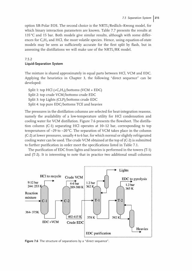
Split 1: top HCl (+C 2 H 2 )/bottoms (VCM + EDC) Split 2: top crude VCM/bottoms crude EDC Split 3: top Lights (CLP)/bottoms crude EDC Split 4: top pure EDC/bottoms TCE and heavies
The pressures in the distillation columns are selected for heat - integration reasons, namely the availability of a low - temperature utility for HCl condensation and cooling water for VCM distillation. Figure 7.6 presents the fl owsheet. The distilla-tion column (C - 1) separating HCl operates at 10 – 12 bar, corresponding to top temperatures of − 29 to − 20 ° C. The separation of VCM takes place in the column (C - 2) at lower pressures, usually 4 to 6 bar, for which normal or slightly refrigerated cooling water can be used. The crude VCM obtained at the top of (C - 2) is submitted to further purifi cation in order meet the specifi cations listed in Table 7.1 .
The purifi cation of EDC from lights and heavies is performed in the towers (T - 1) and (T - 2). It is interesting to note that in practice two additional small columns
Figure 7.6 The structure of separations by a “ direct sequence ” .
7.5 Separation System 215

216 7 Vinyl Chloride Monomer Process
are provided to minimize the losses in EDC passed in distillate and bottoms, respectively. These columns also have an important role in process dynamics and control. In addition, the chemical conversion of the nonsaturated impurities to heavies may take place by injecting chlorine either in a separate reactor or directly in the column (T - 1).
The above separation sequence, although the most used in industry, is not unique. Another possibility would consist of adopting the “ indirect sequence ” . In this case, EDC separates in the fi rst split as bottoms, followed by VCM/HCl distil-lation, as pictured in Figure 7.7 (left - hand). This alternative is penalized by exces-sive bottom temperature in the fi rst split at pressures above 5 bar. In addition, in the second step an intermediate compression would be necessary for an effi cient separation HCl/VCM.
However, another interesting solution can be imagined, as in Figure 7.7 (right - hand). Indeed, a sloppy split in a prefractionator (S - 1) can make the reboiler tem-perature compatible to heat integration by process/process exchange. The prefractionator could be simple fl ash or reboiled stripping. It follows two distilla-tion columns for HCl and VCM separations. The last reboiled stripper column (C - 3) delivers EDC for fi nal purifi cation. This solution ensures higher quality for VCM, obtained as top distillate and free of HCl. In addition, the scheme can better accommodate the heat integration between different columns, by varying the pres-sure levels. This scheme was acknowledged in an industrial paper [17] .
7.6 Material - Balance Simulation
The reactor and separation systems described above can be assembled in a fl ow-sheet. In a preliminary simulation, the goal is closing the material balance with recycles. In a fi rst approach shortcut models may be used to simulate the distilla-
Figure 7.7 Alternatives for the separation of the HCl/VCM/EDC mixture.

tion columns. This approach guarantees the consistency of the material balance. Later, rigorous models are inserted for fi nishing the sizing.
Figure 7.8 presents the fl owsheet. Fresh and recycled EDC enters the distilla-tion column of lights C101. The next column C102 separates the heavies. After evaporation and temperature rise the vapor enters the cracking reactor PYRO. A second stoichiometric reactor PYROS describes the secondary reactions. The quench of the outlet mixture consists of cooling with recycled EDC. After cooling and fl ash separation the mixture is sent to HCl separation in the distillation column C201. The last column C - 2 supplies crude VCM and EDC to be recycled. Sampled values for temperature, pressure and duties are displayed for information.
When simulating this fl owsheet convergence problems appear. These may be attributed to the following reasons:
1. thermodynamic behavior of some impurities, 2. confl icts between specifi cation of units and convergence requirements.
Firstly, the removal of TRI in the bottom of C101 is hindered by the azeotrope that this impurity forms with the EDC. Another constraint is that the concentration of TRI in the purifi ed EDC should be kept below 1000 ppm to avoid coke formation during pyrolysis. The recovery of CLP in the top distillate must be quantitative, but with less than 8 wt% concentration to prevent polymerization. As a conse-quence, a substantial amount of EDC should be entrained in the top distillate. For separation reasons, both the number of trays and the L/V traffi c in the column C101 should be suffi ciently high. Good convergence is obtained with 35 theoretical stages and a boil - up ratio of 0.6. In principle, the removal of TRI could be enhanced by a side stream. Indeed, the liquid concentration profi le indicates a maximum of TRI near the top, but the simulation shows that this effect is rather limited. Only by allowing enough EDC in the top distillate can the removal of both TRI and CLP be quantitative.
Similarly, the column C102 should be designed for advanced removal of TCE and of other heavies by allowing some EDC to be drawn in the bottom product. As a result, the excess of EDC in the top of C101 and in the bottom of C102 should be recycled by means of supplementary small columns, as shown in Figure 7.6 . It is interesting to note that if the design of these columns is not appropriate, snowball effects occur by accumulation of impurities [9, 10] . We recall that a snowball consists of large variations in the recycle streams generated by small variations in the input or output streams because of excessive sensitivity of the system. Snowball may be an indication about the occurrence of possible multiple steady states.
The simulation of the columns C201 and C202 needs careful analysis of speci-fi cations. The design of HCl column must ensure both high recovery and purity of HCl in order to prevent accumulation in recycle. About 30 stages and refl ux fl ow rate at 1000 kg/h are convenient. The distillate fl ow rate should ensure com-plete HCl recovery, but with minimum losses in VCM. From the simulation viewpoint, making use of a “ design specifi cation ” is the best way to fi nely adjust
7.6 Material-Balance Simulation 217

218 7 Vinyl Chloride Monomer Process
Figu
re 7
.8 P
relim
inar
y fl o
wsh
eet
of t
he V
CM
pla
nt.

the distillate rate. The next column C202 offers the choice between specifying the top distillate and bottoms fl ow rate, or the relative mode distillate/feed. We found that the most reliable manner is fi xing the rate of the bottom product. This means keeping constant the recycle fl ow rate of EDC at a value compatible with the per-formance of the chemical reactor. This approach is equivalent to keeping constant the inlet reactor fl ow, also a good strategy from the plantwide control viewpoint (see Chapter 4 ).
7.7 Energy Integration
Table 7.8 presents the pressures, temperatures and duties of the candidate streams for heat integration. The reactor outlet has substantial energetic potential. Note that the dew point is 152 ° C at 15 bar. The H – T curve shows that the heat content of the vapor part is suffi cient for covering the duty of the EDC evaporator. This solution has the advantage of feeding the reactor with gaseous EDC and preventing the coke formation. If the evaporation takes place inside the furnace an upsetting effect can take place [16] . Note that the position of the heat exchanger can be before or after the quench. The second alternative offers better protection against fouling, while the temperature driving force remains high.
The preheater of the gaseous EDC is integrated in the convection zone of the furnace. The pyrolysis reactor is placed in the radiation zone. The design of the furnace is a complex aspect not treated here, in which heat integration plays an
Table 7.8 Streams for heat integration.
Hot streams P, T , duty bar, deg. C, MW
Cold streams P, T , duty bar, deg. C, MW
Flue gases furnace 1.013; 1100 → 400 9.48
Reactor inlet
Reaction mixture
22.0; 216.0 → 435.0 5.53 21.0; 435.0 → 540.0
Reactor outlet Q1 - Q2 - Q3 - Q4
16.0; 441.8 → 135.0; − 10.43
EDC vaporizer F3 - F4
19; 121.0 → 215.6; 7.50
Separation inlet S4 - S4A - S4B
14.0; 135.0 → 30.0; − 7.28
EDC preheater F4 - R1
18.0; 215.6 → 435.0; 530
Condenser C101 1.2; 93.5 → 90.2; − 3.58
Reboiler C101 1.5; 103.8 → 104.2; 3.18
Condenser C102 3.0; 124.5 → 123.1; − 3.42
Reboiler C102 3.5; 130.4 → 135.6; 3.73
Condenser C201 11.0; − 27.6 → − 28.9; − 0.72
Reboiler C201 11.5; 80.8 → 91.0; 2.45
Condenser C202 3; 20.8 → 16.9; − 2.98
Reboiler C202 3.5; 128.5 → 128.6; 2.45
7.7 Energy Integration 219

220 7 Vinyl Chloride Monomer Process
Figu
re 7
.9 F
low
shee
t co
nfi g
urat
ion
befo
re h
eat
inte
grat
ion.

important role too. For example, the heat content of the fl ue gases can be used for both feed preheating and steam generation.
The enthalpy of the reactor outlet stream can be used for ensuring the reboiler duty of the column C202 (2.45 MW). This operation is simulated by the heat exchanger COOL2. The hot - outlet temperature at 139 ° C ensures a minimum temperature difference of 10 ° C with respect to the reboiler. Condensation starts during cooling, the fi nal vapor fraction being about 81%. The residual heat may be rejected against air or water cooling. Placing a small heat exchanger before fl ash separation is recommended for better temperature control. Splitting the liquid after fl ash is necessary for the quench.
The resulting vapor and liquid streams are merged again, but cooled low enough to ensure a convenient thermal condition of the feed for C201. The optimum temperature is around 30 ° C, which minimizes the load of the condenser, driven by an expensive refrigeration agent. A part of the heat can be used to cover the reboiler duty of C201 by the unit HX1. An outlet temperature of 105 ° C gives a driving force at the cold end of about 14 ° C. The remaining stream to C201 still has a signifi cant potential of about 4.86 MW, but the temperature level is too low for heat integration.
An interesting energy saving arises by the integration of columns C101 and C102 by playing on pressures at 1.1 and 3 bar, respectively. The condenser of C102 has a duty of 3.42 MW, high enough to cover the reboiler duty of C101 of 3.18 MW. Note that the reboiler of C102 has a relatively moderate temperature (136 ° C), so that MP steam can be used for heating, in turn generated by upgrading the LP steam produced by direct hot chlorination, or imported from the other sections of the plant.
After this exercise, we may conclude that by adequate heat integration the energy requirements of the pyrolysis/distillation section can be reduced considerably. The hot utility can be covered by internal means, namely by the HP steam raised in the oxychlorination stage. Refrigeration is necessary for low - temperature separa-tion of HCl, but the amount can be minimized by accurate column design. Impor-tant saving of energy in driving the distillation columns can be achieved. The hot reactor effl uent can be used to drive the reboilers of the columns for separating HCl and VCM. Supplementary saving can be obtained by the direct integration of the columns for the EDC purifi cation. However, care should be paid to control-ability aspects.
The above heat - integration scheme is obviously not unique. Figure 7.10 shows the scheme proposed by Lurgi [18] on its website. No temperature indications are given, but after this exercise it can be easily understood. It is interested to observe that the scheme makes use of two FEHE units to recover the energy of the outlet gases to preheat the inlet reactor mixture both for entering the preheater and the reaction zone to the reaction temperature. No unstable behavior take place since the pyrolysis reaction is endothermic. The quencher is in fact a multifl ash separator that delivers separate gas and liquid feeds for the HCl column. The selection of pressures can lead to several options that might be explored by the reader.
7.7 Energy Integration 221

222 7 Vinyl Chloride Monomer Process
7.8 Dynamic Simulation and Plantwide Control
Dynamic simulation is prepared by sizing the units. For each unit with signifi cant dynamics, the holdup is calculated by assuming a residence time, typically in the range of 5 – 10 min, and fi nding the corresponding volume. For the distillation columns tray sizing is necessary. Fast units, such as heat exchangers, pumps or mixers can be considered as instantaneous. Note that simulating a model of type “ reactor - with - specifi ed - temperature ” is not possible, because of a high - index problem. As a result, both the temperature of the heating medium (burn gases) and the heat - transfer coeffi cient have to be specifi ed. This approach is very approxi-mate as the heat is transferred mainly by radiation. Although the performance of the pyrolysis reactor described in Section 7.4.2 could be reproduced with small adjustments of the reactor - inlet temperature and reactor length, conver-gence of the steady - state simulation with closed recycle is very diffi cult. As alterna-tive strategy the open - recycle simulation is exported to Aspen Dynamics, which provides the basic inventory controllers. After adding temperature controllers around heat exchangers, the recycle was closed and simulation was run until a steady state was obtained. Then, control of the distillation columns was implemented.
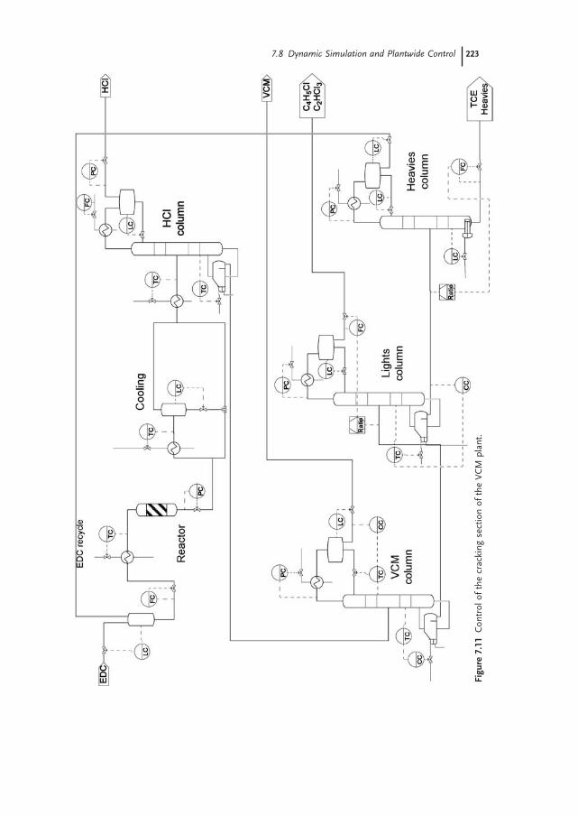
The plantwide control structure is presented in Figure 7.11 . The most interest-ing points are discussed below. Firstly, we fi x the reactor - inlet fl ow rate and feed the fresh EDC on level control. Control of reactor and cooling section does not raise any problem. Since the HCl column operates mainly as a stripper, the tem-perature in the bottom is controlled by manipulating the steam rate, so as to ensure
Figure 7.10 Simplifi ed PFD of the EDC cracking/VCM separation section with heat - integration scheme (after Lurgi Company). (1) EDC preheater, (2) Feed effl uent heat exchanger (FEHE), (3) EDC quencher condenser, (4) HCl column condenser, (5) VCM column condenser.
7.8 Dynamic Simulation and Plantwide Control 223
Figu
re 7
.11
Con
trol
of
the
crac
king
sec
tion
of t
he V
CM
pla
nt.

224 7 Vinyl Chloride Monomer Process
that HCl is completely removed from the liquid product. At the top of the column the cooling duty is constant, the refl ux fl ow controls level in the condenser drum, while the fl ow of the vapor product controls the pressure.
At the VCM column, the purity of the product stream (chloroprene less than 10 ppm), is controlled using a concentration/temperature cascade scheme, with refl ux as the manipulated variable. Feed - rate changes could be accounted for by keeping constant the ratio reboiler duty/feed through feedforward control. However, when the plant was disturbed, a relatively large amount of VCM escaped in the bottom and ended in the distillate of the lights column. Therefore, a second concentration – temperature cascade controlling the bottoms composition was implemented.
The task of the lights column is to remove the light components from the recy-cled EDC, with chloroprene and tri - chloroethylene being the most important impurities. Therefore, a concentration - cascade scheme was implemented, with chloroprene concentration and reboiler duty as controlled and manipulated vari-ables, respectively. The distillate to feed ratio was kept constant using feedforward control. This ratio can be used to adjust the level of tri - chloroethylene in the bottom product. The level in the condenser drum was controlled by the refl ux. Note that fi xing the refl ux and controlling the level by distillate does not work, because the distillate rate is very small.
Control of the heavies column is simpler. A fi xed fraction of the feed is taken as bottom product, in a feedforward manner. The reboiler duty controls the level in the column sump. Note that this arrangement, which is required because of the small bottoms stream, cannot be implemented if a kettle reboiler is used. The column is operated at constant refl ux, while the distillate rate controls the condenser level.
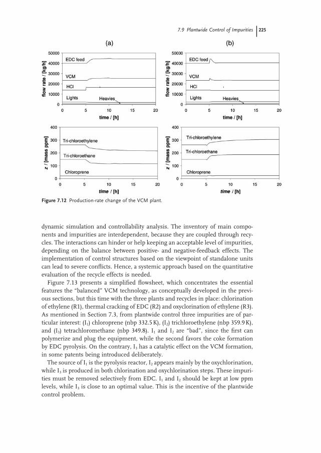
Figure 7.12 (a) shows results of the dynamic simulation, obtained when a dis-turbance of +25 ° C in the temperature of the burn gases was introduced at time t = 5 h. The disturbance increases the reaction rate, which results in more VCM and HCl. As the recycle decreases, more fresh EDC is necessary to keep constant the reactor - inlet stream. Small variations in the fl ow rates of lights and heavies are observed. In the same time, the level of impurities at the reactor inlet decreases.
In the second simulation (Figure 7.12 b), the reactor - inlet fl ow was increased from 74 000 kg/h to 81 500 kg/h. Initially, the amounts of VCM produced and of fresh EDC fed increase. However, these fl ows soon decrease to the initial values. This means that, when reaction conditions are fi xed, production - rate changes can be achieved only at the expense of large variations of the recycle fl ow. Moreover, all the fl ow rates are very sensitive to disturbances if a control structure fi xing the fl ow rate at the plant inlet is used.
7.9 Plantwide Control of Impurities
The inventory of impurities is a plantwide control problem acknowledged in industry for a long time. This problem can be handled systematically by means of
dynamic simulation and controllability analysis. The inventory of main compo-nents and impurities are interdependent, because they are coupled through recy-cles. The interactions can hinder or help keeping an acceptable level of impurities, depending on the balance between positive - and negative - feedback effects. The implementation of control structures based on the viewpoint of standalone units can lead to severe confl icts. Hence, a systemic approach based on the quantitative evaluation of the recycle effects is needed.
Figure 7.13 presents a simplifi ed fl owsheet, which concentrates the essential features the “ balanced ” VCM technology, as conceptually developed in the previ-ous sections, but this time with the three plants and recycles in place: chlorination of ethylene (R1), thermal cracking of EDC (R2) and oxyclorination of ethylene (R3). As mentioned in Section 7.3 , from plantwide control three impurities are of par-ticular interest: (I 1 ) chloroprene (nbp 332.5 K), (I 2 ) trichloroethylene (nbp 359.9 K), and (I 3 ) tetrachloromethane (nbp 349.8). I 1 and I 2 are “ bad ” , since the fi rst can polymerize and plug the equipment, while the second favors the coke formation by EDC pyrolysis. On the contrary, I 3 has a catalytic effect on the VCM formation, in some patents being introduced deliberately.
The source of I 1 is the pyrolysis reactor, I 2 appears mainly by the oxychlorination, while I 3 is produced in both chlorination and oxychlorination steps. These impuri-ties must be removed selectively from EDC. I 1 and I 2 should be kept at low ppm levels, while I 3 is close to an optimal value. This is the incentive of the plantwide control problem.
Figure 7.12 Production - rate change of the VCM plant.
7.9 Plantwide Control of Impurities 225

226 7 Vinyl Chloride Monomer Process
The plant simulation considers only a reduced number of units, but dynamically representative, as follows. Crude EDC from R1 and R3 are sent to washing/drying in the unit S0. Dissolved gases and very light impurities are removed in S1, and further in the distillation column S4, which is the exit point of the light impurities. After pretreatment, the crude EDC is sent to purifi cation in the distillation column S2, which is the key unit of the separation system. This column receives crude EDC from three reactors. It is also the place where three large recycle loops cross. The top distillate of S2 should remove the light impurities mentioned above, while the purifi cation of EDC from heavies is continued in the distillation columns S3 and S5.
The separation of impurities in S2 is affected by volatility constraints. At 350 K, the top temperature, the volatility of I 1 , I 2 , and I 3 relative to EDC is about 1.9, 0.94 and 1.6. Therefore, the top distillate of S2 can easily remove I 1 and I 3 , but not I 2 . Note also that the top distillate of S2 cannot contain more than 8% I 1 .
To prevent the accumulation of I 2 , a side stream drawn from S2 is sent to the reactor R1, where chlorination to heavies takes place. Because of the constraint on I 1 , the top distillate of S2 carries with it a signifi cant amount of EDC, which has to be recovered and recycled to S2 by the column S4. By returning the bottom of S4 to the reactor R1, some amounts of impurities I 1 and I 2 can eliminated, but this operation complicates the fl owsheet. Therefore, it is rational to introduce a specialized reactor for the conversion of nonsaturated impurities in heavies by liquid - phase chlorination. This new reactor, designated by R4, placed between S2 and S4, gives the opportunity to develop new fl owsheet alternatives by rerouting the streams, as depicted in Figure 7.14 . Thus, the heavies created by the conversion of lights can leave the plant through S5 (alternative A), return to S2 (alternative B) or pass directly to S3 (alternative C).
Note that all heavy impurities are removed by the columns S3 and S5, which work in tandem in order to limit the losses in EDC. With respect to design, S2 is
Figure 7.13 Base - case fl owsheet of a balanced VCM process for handling impurities.

a big column with a large number of theoretical stages operating at high refl ux. The separation in S3 requires only a few stages. On the contrary, S4 and S5 are small units but of particular importance, being the only exit of light and heavy impurities, respectively.
After thermal cracking the reaction mixture is quenched and cooled (nonpre-sented). The recovery of HCl and the separation of VCM from unreacted DCE take place in units S6 and S7, respectively.
From a simulation viewpoint units S0, S6 and S7 may be considered black - boxes. On the contrary, S1 to S5 are simulated by rigorous distillation columns, as sieve trays. In the steady state all the reactors can be described by a stoichio-metric approach, but kinetic models are useful for R1, R2 and R4 in dynamic simulation [7, 8] . As shown before, the reaction network should be formulated so as to use a minimum of representative chemical species, but respecting the atomic balance. This approach is necessary because yield reactors can misrepresent the process.
The quality of the EDC sent to pyrolysis must fulfi l strict purity specifi cations, but too low an impurity level implies high energy consumption. The concentra-tions of I 1 and I 2 in the bottom of S2 must not exceed 100 and 600 ppm, respec-tively, while the concentration of I 3 must be kept around its optimal value at 2000 ppm. It is worth mentioning that these contradictory requirements cannot be fulfi lled by any standalone design of S2. The effective control of impurities becomes possible only by exploiting the positive - feedback effects of the recycle loops that are balanced by the negative - feedback effects of chemical conversion and exit streams.
The three quality specifi cations regarding the impurities in EDC, available by direct concentration measurements, such as by IR spectroscopy or online chroma-tography, are the outputs of the plantwide control problem. The degrees of freedom indicate as fi rst choice manipulated variables belonging to the large column S2:D2 – distillate fl ow rate, SS2 – side - stream fl ow rate, and Q2 – reboiler duty. We may also consider manipulated variables belonging to the small column
Figure 7.14 Flowsheet alternatives for the removal of impurities.
7.9 Plantwide Control of Impurities 227
228 7 Vinyl Chloride Monomer Process
S4, connected to S2 by a recycle, but dynamically faster. Thus, supplementary inputs are: D4 – distillate fl ow rate, and Q4 – reboiler duty. A major disturbance of the material balance can be simulated by a step variation in an external EDC feed. A second signifi cant disturbance is the amount of impurity I 3 introduced in the plant.
The base case and three alternatives were evaluated by controllability analysis [7, 8] , fi rstly at steady - state. The conclusion is that the loops Q2 (reboiler duty) – I 1 and SS2 (side - stream fl ow) – I 2 are more interactive than the loop controlling I 3 with D2, D4 or Q4. The use of D4 offers the best decoupling of loops. In the base case and alternative B the effect of the variables belonging to S4 on I 3 is enhanced by closing the other loops, while in alternatives A and C this effect is hindered. However, at this point there is not a clear distinction between the base case and alternatives. A dynamic controllability analysis is needed.
When the interactions between controllers are taken into account, only two controllers, Q2 – I 1 and D4 – I 3 , are suffi cient to keep I 2 between bounds, because the disturbances affect the outputs in the same direction. The reboiler duty Q2 and the side draw SS2 also affect the impurities I 1 and I 2 in the same direction. So both controllers are supporting each other in rejecting the disturbances. Because the power of Q2 is much larger than SS2, the controller Q2 – I 1 is dominating, and the loop SS2 – I 2 is not needed. Hence, leaving I 2 free, but having the guarantee of a bounded variation, is a rational compromise that preserves the robustness of the control system. Hence, the plantwide control objective could be achieved with only two control loops, Q2 – I 1 and D4 – I 3 , which over a practical range of frequency are almost decoupled. Fully dynamic simulation confi rmed the analysis by imple-menting the controllers Q2 – I 1 and D4 – I 3 as P - type only. Note that using manipu-lated variables from different units is not a current control practice. However, the principle of proximity is preserved, because the columns S2 and S4 are dynami-cally adjacent.
The above analysis emphasizes that the most signifi cant improvement came from the chemical conversion of impurities by diminishing the positive feedback of recycles. Controllability study and closed - loop simulation indicate that the base case and alternative B have the best dynamic properties. The last modifi cation offers the shortest path of impurities and faster dynamics, together with better protection against plugging. The revamp of the plant would consist in adding the small reactor R4 for chlorination of impurities, repiping the connection from S4 to S2 and replacing the internals in the lower part of the column S2 with fouling - resistant trays or packing.
Summing up, if the inventory of the main components can be handled by local control loops, the inventory of impurities has essentially a plantwide character. The rates of generation, mainly in chemical reactors, and of depletion (exit streams and chemical conversion), as well as the accumulation (liquid - phase reactors, dis-tillation columns and reservoirs) can be balanced by the effect of recycles in order to achieve an acceptable equilibrium state. Interactions through recycles can be exploited to create plantwide control structures that are not possible from a stand-alone unit viewpoint.

References 229
7.10 Conclusions
The VCM case study emphasizes the complexity of designing a large chemical plant with an intricate structure due to several reactors and separation sections. A balanced process is designed such that only VCM leaves the plant, with raw materials effi ciency close to stoichiometry.
Characteristic of this process is the formation of a large spectrum of chloro - hydrocarbon impurities. These originate in the three reaction systems, chlorina-tion, oxychlorination and pyrolysis. The fi rst two are sources of the intermediate EDC, which is a reactant in the third. Some impurities are circulating between the three reactors due to recycle fl ows. In this way the purifi cation of EDC becomes an intricate problem with plantwide character. Therefore, the handling of impuri-ties implies not only their removal by distillation, but also the minimization at source, namely by improving the reaction conditions. In particular, the yield of pyrolysis can be enhanced by making use of initiators, some being produced and recycled in the process itself. The handling of impurities is at the origin of control problems regarding the plantwide material balance. Chemical conversion of impu-rities accumulating in recycle prevents the occurrence of snowball effects that otherwise will affect the operation of reactors and separators.
The VCM process offers good opportunities for energy saving by heat integra-tion, namely in distillations. Direct chlorination and particularly oxychlorination are important sources of energy.
References
1 Ullmann ’ s Encyclopaedia, Chlorinated Hydrocarbons, vol. A6, 263 – 384, 1993
2 Weissermel , K. , Arpel , H.J. , Industrial Organic Chemistry , Wiley - VCH , 2003
3 Cowfer , J.A. , Magistro , A.J. , Vinyl
Chloride, in Kirk - Othmer Encyclopedia of
Chemical Technology , 23 , 865 – 883 , 1992 4 McPherson , R. , Starks , C.M. , Fryar , G.J. ,
Vinyl chloride monomer . . . what you should know , Hydrocarbon Process. , pp. 75 – 92 , March 1979
5 Wong , E.W. , Ambler , C.P. , Baker , W.J. , Parks , J.C. , Producing high purity VCM product , Hydrocarbon Processing , 129 – 134 , August 1992
6 Saeki , Y. , Emura , T. , Technical progresses for PVC production , Prog.
Polym. Sci. , 2055 – 2131 , 2002 7 Groenendijk , A.J. , Dimian , A.C. , Iedema ,
P.D. , System approach for evaluating dynamics and plantwide control of
complex plants , AIChE J. , 46 , 119 – 132 , 2000
8 Dimian , A.C. , Groenendijk , A. , Iedema , P.D. , Recycle interaction effects on the control of impurities in a complex plant , Ind. Eng. Chem. Res. , 40 , 5784 – 5794 , 2001
9 Bostwick , L.E. , Recovering chlorine from HCl , Chem. Eng. , 10 , 1986
10 Clegg , I.M. , Hardman , R. , Vinyl chloride production process, US Pat 5728905 , 1998
11 Orejas , J.A. , Model evaluation for an industrial process of direct chlorination of ethylene in a bubble - column reactor , Chem. Eng. Sci. , 56 , 513 – 522 , 2001
12 Wachi , S. , Morikawa , H. , J. Chem. Eng.
Japan , 19 , 437 – 443 , 1986 13 Ranzi , E. , Dente , M. , Rovaglio , M. ,
Pyrolysis and chlorination of small hydrocarbons , Chem. Eng. Commun. , 117 , 17 – 39 , 1992