7 thermal applications - cientificosaficionados.comcientificosaficionados.com/energia...
TRANSCRIPT
THERMAL APPLICATIONS:COOLING SYSTEMS
Modern Industrial Assessments 211
7 THERMAL APPLICATIONS
7.1. COOLING SYSTEMS
For process cooling it is always best from the standpoint of energy conservation to use the least expensive form of energy first. That is, for a piece of equipment or a process that is air cooled, first use outside air (an economizer) if the outside air temperature is low enough. The next step, in appropriate climates, would be to use direct evaporative cooling. This is a process in which air passing through water droplets (a swamp cooler) is cooled, as energy from the air is released through evaporation of the water. Evaporative cooling is somewhat more energy intensive than the economizer but still provides some relatively inexpensive cooling. The increase in energy use is due to the need to pump water. Indirect evaporative cooling is the next step up in energy use. Air in a heat exchanger is cooled by a second stream of air or water that has been evaporatively cooled, such as by a cooling tower and coil. Indirect evaporative cooling may be effective if the wet-bulb temperature is fairly low. Indirect evaporative cooling involves both a cooling tower and swamp cooler, so more energy will be used than for the economizer and evaporative cooling systems because of the pumps and fans associated with the cooling tower. However, indirect cooling systems are still less energy intensive than systems that use a chiller. The final step would be to bring a chiller on line. Many plants have chillers that provide cooling for various plant processes. Chillers consist of a compressor, an evaporator, an expansion valve, and a condenser and are classified as reciprocating chillers, screw chillers, or centrifugal chillers, depending on the type of compressor used. Reciprocating chillers are usually used in smaller systems (up to 25 tons [88 kW]) but can be used in systems as large as 800 tons (2800 kW). Screw chillers are available for the 80 tons to 800 tons range (280 kW to 2800 kW) but are normally used in the 200 tons to 800 tons range (700 kW to 2800 kW). Centrifugal chillers are available in the 200 tons to 800 tons range and are also used for very large systems (greater than 800 tons [2800 kW]). The evaporator is a tube-and-shell heat exchanger used to transfer heat to evaporate the refrigerant. The expansion valve is usually some form of regulating valve (such as a pressure, temperature, or liquid-level regulator), according to the type of control used. The condenser is most often a tube-and-shell heat exchanger that transfers heat from the system to the atmosphere or to cooling water. 7.1.1. Introduction
This section contains information pertaining to cooling systems, particularly chiller systems. Refer to Brief #4 "Outside Air Economizers," Brief #5, "Evaporative Cooling," Brief #6, "Cool Storage," and Brief #7, "Heat Recovery from Chillers" in DSM Pocket Guidebook, Volume 2: Commercial Technologies for information relating to cooling systems that may be found in industry. Topics discussed
THERMAL APPLICATIONS:COOLING SYSTEMS
Modern Industrial Assessments 212
in this section include condenser water and chilled water temperature reset at the chiller, hot-gas defrost of chiller evaporator coils, and two-speed motors for cooling tower fans. 7.1.2. Cooling Towers
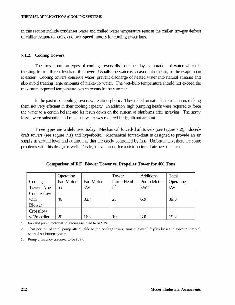
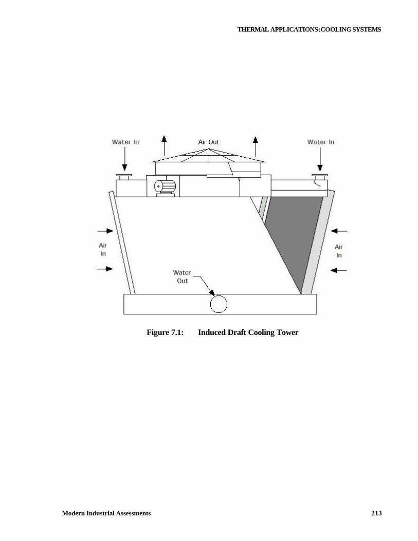
The most common types of cooling towers dissipate heat by evaporation of water which is trickling from different levels of the tower. Usually the water is sprayed into the air, so the evaporation is easier. Cooling towers conserve water, prevent discharge of heated water into natural streams and also avoid treating large amounts of make-up water. The wet-bulb temperature should not exceed the maximum expected temperature, which occurs in the summer. In the past most cooling towers were atmospheric. They relied on natural air circulation, making them not very efficient in their cooling capacity. In addition, high pumping heads were required to force the water to a certain height and let it run down on the system of platforms after spraying. The spray losses were substantial and make-up water was required in significant amount. Three types are widely used today. Mechanical forced-draft towers (see Figure 7.2), induced-draft towers (see Figure 7.1) and hyperbolic. Mechanical forced-draft is designed to provide an air supply at ground level and at amounts that are easily controlled by fans. Unfortunately, there are some problems with this design as well. Firstly, it is a non-uniform distribution of air over the area.
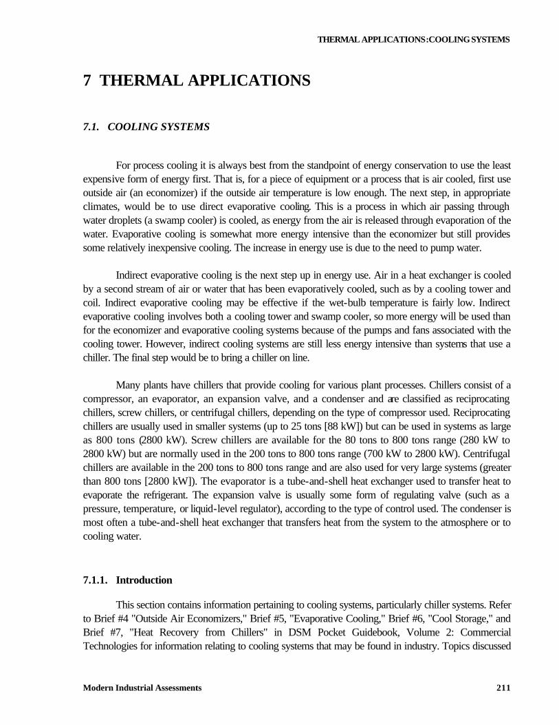
Comparison of F.D. Blower Tower vs. Propeller Tower for 400 Tons
Operating Tower Additional Total Cooling Fan Motor Fan Motor Pump Head Pump Motor Operating Tower Type hp kW1 ft2 kW3 kW Counterflow with Blower
40 32.4 23 6.9 39.3
Crossflow w/Propeller 20 16.2 10 3.0 19.2
1. Fan and pump motor efficiencies assumed to be 92%.
2. That portion of total pump attributable to the cooling tower; sum of static lift plus losses in tower’s internal water distribution system.
3. Pump efficiency assumed to be 82%.
THERMAL APPLICATIONS:COOLING SYSTEMS
Modern Industrial Assessments 213
Figure 7.1: Induced Draft Cooling Tower
THERMAL APPLICATIONS:COOLING SYSTEMS
Modern Industrial Assessments 214
AirIn
WaterSprays
AirOut
WaterOut
Figure 7.2: Mechanical Forced-Draft Cooling Tower
Secondly, the vapor is recirculated from the discharge into the inlet causing ice formation on the blades of draft fans (only when the temperatures drop low enough in the winter months). Thirdly, the physical limitations of the fan size might prove a problem. In case of induced-draft towers, the fan is mounted on the top of the roof. This arrangement improves air distribution. The make-up of water is also less. Hyperbolic tower is based on the chimney effect. The effect of the chimney eliminates the need for fans which are necessary for both induced-draft and mechanical forced-draft cooling towers. If the tower is of a substantial height, above 250 feet, the tower orientation should be with its broad side to the prevailing winds in the region. Shorter towers should have long axis parallel to the prevailing winds.
THERMAL APPLICATIONS:COOLING SYSTEMS
Modern Industrial Assessments 215
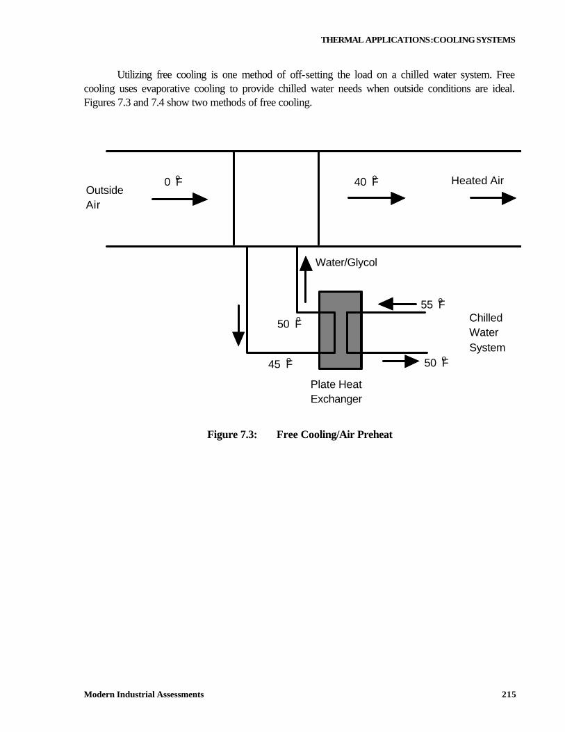
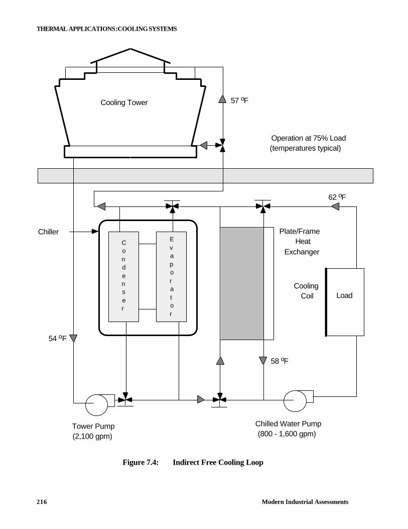
Utilizing free cooling is one method of off-setting the load on a chilled water system. Free cooling uses evaporative cooling to provide chilled water needs when outside conditions are ideal. Figures 7.3 and 7.4 show two methods of free cooling.
Heated Air40 F0 F
55 F
50 F
ChilledWaterSystem
50 F
45 F
OutsideAir
Water/Glycol
Plate HeatExchanger
o
oo
o
o
o
Figure 7.3: Free Cooling/Air Preheat
THERMAL APPLICATIONS:COOLING SYSTEMS
Modern Industrial Assessments 216
Cooling Tower
Chiller Plate/FrameHeat
Exchanger
CoolingCoil Load
Operation at 75% Load(temperatures typical)
Tower Pump(2,100 gpm)
Chilled Water Pump(800 - 1,600 gpm)
62 oF
58 oF
54 oF
57 oF
Condenser
Evaporator
Figure 7.4: Indirect Free Cooling Loop

THERMAL APPLICATIONS:COOLING SYSTEMS
Modern Industrial Assessments 217
Free Cooling (Water Side Economizer) Define Operating Conditions
Peak Load Design Conditions
Off Season Design Conditions
Comfort Cooling 700 Tons 200 Tons Data Processing 300 Tons 300 Tons
Total Load 1000 Tons 500 Tons Alternate
Number One Alternate
Number Two Flow Rate 2400 GPM 1200 GPM 2400 GPM
Returning Temperature 55ºF 60ºF 60ºF Leaving Temperature 45ºF 50ºF 55ºF
7.1.3. Typical Performance Improvements
Improvements in chilled water systems are described in the following sections. Thorough understanding of the operation and knowing all local conditions (temperatures, prevailing winds etc.) are keys to providing an accurate analysis of the problem. Condenser Water Temperature Adjustment
Description The power consumption of any chiller increases as the condensing water temperature rises. This is because, as the condenser temperature increases, the pressure rise across the compressor increases and, consequently, the work done by the compressor increases. Condensing water temperature setpoints are typically in the range between 65ºF and 85ºF, but can be as low as 60ºF. In many cases the setpoint temperature is in the middle of the range, at about 75ºF. A rule of thumb is that there is a 0.5% improvement in chiller efficiency for each degree Fahrenheit decrease in the setpoint temperature for the condenser water. The improvement tends to be higher near the upper range of setpoint temperatures and decreases as the setpoint temperature decreases. The amount of allowable decrease in the setpoint temperature must be determined by a detailed engineering analysis that includes the following: the system capacity, minimum requirements for the plant process served by the condenser water system, and number of hours per year that the wet bulb temperature is below a given value. Definitions Condenser - The unit on the chiller in which heat is transferred out of the refrigerant. Cooled
condensing water flows over tubes containing a vaporized refrigerant in a tube-and-shell heat exchanger. As the refrigerant cools, it condenses into a liquid and releases heat to the condensing water.
THERMAL APPLICATIONS:COOLING SYSTEMS
Modern Industrial Assessments 218
Condensing Water - Water that has been cooled in a cooling tower that is used to condense vaporized refrigerant in the condenser.
Applicability Facility Type - Any facility that has a chiller. Climate - All climates. It is advantageous to reduce the condensing water temperature in both humid
and dry climates. Demand-Side Management Strategy - Strategic conservation. For More Information ASHRAE Handbook, 1996 Equipment, American Society of Heating, Refrigerating and Air Conditioning Engineers, Inc., Atlanta, GA, 1988, Ch. 17. Industrial Assessment Center (IAC). Contact the IAC nearest to your area.
Condenser Water Supply Temperature Reset: Costs and Benefits1
Installed Costs Energy Savings Cost Savings Simple Payback Options ($)2 (MMBtu/yr) ($/yr)3 (yr)
Condenser Water Supply
2,678 498 6,217 0.4
Temp. Reset 1. Tabulated data were taken from the Industrial Assessment Center (IAC) database. All values are averages based
on the data base data. The implementation rate for this measure was 67%. 2. One example from the IAC data base to further clarify the costs is as follows: Resetting the condenser water
temperature at an electronics plant resulted in energy and cost savings of 58,218 kWh/yr and $2,390/yr. The implementation cost was $200.
3. The energy cost savings are based on proposed dollar savings from the IAC report, usually almost identical to actual savings reported from the facility.
Chilled Water Supply Temperature Adjustment
Description The efficiency of chillers increases as the chilled water temperature increases. This is because, in order to obtain lower temperature chilled water, the refrigerant must be compressed at a higher rate, which in turn increases the compressor power requirements and decreases the efficiency of the chiller. There is approximately a 1% increase in efficiency for each degree Fahrenheit increase in the chilled water setpoint temperature. The efficiency increase tends to be higher near the lower temperatures in the setpoint range and decreases as the setpoint temperature increases. The amount of allowable increase must be determined by a detailed engineering analysis that evaluates the load requirements from the chiller, the design chilled water temperature, and other aspects of the system. It is not uncommon to find chilled water setpoints that are lower than is required from industrial chillers.
THERMAL APPLICATIONS:COOLING SYSTEMS
Modern Industrial Assessments 219
Definitions Evaporator - The unit on the chiller in which heat is transferred to the refrigerant. Warm water flows
over tubes containing a liquid refrigerant in a tube-and-shell heat exchanger. Heat is extracted from the water as the refrigerant vaporizes and the temperature of the water is reduced to the desired chilled water temperature.
Chilled Water - Water in the evaporator that is cooled when heat is removed to vaporize the refrigerant. Applicability Facility Type - Any facility that has a chiller. Climate - All climates. Demand-Side Management Strategy - Strategic conservation. For More Information ASHRAE Handbook, 1996 Equipment, American Society of Heating, Refrigerating and Air Conditioning Engineers, Inc., Atlanta, GA, 1988, Ch. 17. Industrial Assessment Center (IAC). Contact the IAC nearest to your area.
Chilled Water Supply Temperature Reset: Costs and Benefits1
Installed Costs Energy Savings Cost Savings Simple Payback Options ($)2 (MMBtu/yr) ($/yr)3 (yr) Chilled Water Supply
766 384 4,449 0.2
Temp. Reset 1. Tabulated data were taken from the Industrial Assessment Center (IAC) database. All values are averages based
on the data base data. The implementation rate for this measure was 57%. 2. One example from the IAC data base to further clarify the costs is as follows: Resetting the chilled water
temperature in a manufacturing plant resulted in energy savings of 39 MMBtu/yr, a cost savings of $537/yr, and no implementation cost, thus giving an immediate payback.
3. The energy cost savings are based on proposed dollar savings from the IAC report, usually almost identical to actual savings reported from the facility.
Variable Speed (or Two-Speed) Motors for Cooling Tower Fans
Description Cooling tower performance is affected by the outdoor wet-bulb temperature. Higher wet-bulb temperatures correspond to higher air saturation temperatures. As air loses the ability to extract heat from water droplets flowing through a cooling tower (increasing wet-bulb temperature), a higher air flow rate is required to remove the desired amount and reduce the condenser water to the design
THERMAL APPLICATIONS:COOLING SYSTEMS
Modern Industrial Assessments 220
temperature. The cooling water fan motor is often sized to perform under design conditions (i.e., full water flow rate at maximum air flow rate and design wet-bulb temperature). During periods of lower outdoor wet-bulb temperature, the design amount of cooling can be obtained with lower air flow rates. As the air flow rate decreases, the fan speed and the motor power requirements also decrease. It may then be beneficial to install a two-speed motor for the cooling tower fan to reduce the fan motor power consumption. Two-speed motors may be part of new or retrofit construction. Savings for the addition of a two-speed fan motor are estimated based on the number of hours per year that the wet-bulb temperature occurs at various ranges between design wet-bulb and minimum wet-bulb temperatures and the power requirements for various air flow rates. It should also be noted that variable speed drives for fan motors achieve cooling tower energy savings in the same manner as two-speed motors. Definitions Wet-Bulb Temperature - Thermodynamic wet bulb temperature is the temperature at which liquid or
solid water, by evaporating into air, can bring the air to saturation adiabatically at the same temperature. High wet-bulb temperatures correspond to higher air saturation conditions. For example, dry air has the ability to absorb more moisture than humid air, resulting in a lower, wet-bulb temperature.
Applicability Facility Type - Any facility that has a cooling tower. Climate - All climates. It is advantageous to install two-speed motors on cooling towers in both humid
and dry climates; however, the benefits are greater in climates that experience a low wet-bulb temperature.
Demand-Side Management Strategy - Strategic conservation. For More Information Industrial Assessment Center (IAC). Contact the IAC nearest to your area. Motor Master, Washington State Energy Office, Olympia, WA, 1992.
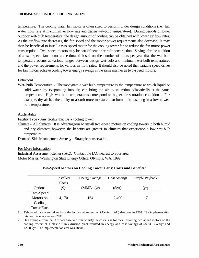
Two-Speed Motors on Cooling Tower Fans: Costs and Benefits1
Installed Costs
Energy Savings Cost Savings Simple Payback
Options ($)2 (MMBtu/yr) ($/yr)3 (yr) Two-Speed Motors on 4,170 164 2,400 1.7
Cooling Tower Fans
1. Tabulated data were taken from the Industrial Assessment Center (IAC) database in 1994. The implementation rate for this measure was 20%.
2. One example from the IAC data base to further clarify the costs is as follows: Installing two-speed motors on the cooling towers at a plastic film extrusion plant resulted in energy and cost savings of 58,335 kWh/yr and $2,680/yr. The implementation cost was $8,900.
THERMAL APPLICATIONS:COOLING SYSTEMS
Modern Industrial Assessments 221
3. The energy cost savings are based on proposed dollar savings from the IAC report, usually almost identical to actual savings reported from the facility.
Hot Gas Defrost
Description Frost builds up on air cooler unit (freezer) evaporator coils when the unit operates at less than 32ºF. Frost is the result of moisture in the air freezing to the coil as the air passes over the coil. The performance of the coil is adversely affected by frost. Frost acts as an insulator and reduces the heat transfer capability of the coil, and it restricts airflow through the coil. Frost buildup is unavoidable and must be removed periodically from the coil. One method of frost removal is to use the hot refrigerant discharge gas leaving the compressor. During the defrost cycle, hot gas is circulated through the coil to melt the frost. Hot-gas defrost systems may be used for all cooling unit capacities and may be included in new or retrofit construction. For retrofit applications, hot-gas defrost systems most often replace electric resistance defrost systems. Using waste heat off the hot-gas side for defrost may result in savings on the order of 10% to 20% of the total system usage. Definitions Hot-Gas - The refrigerant vapor discharged by the compressor. This vapor is superheated; the
temperature of the vapor has been raised above that which normally occurs at a particular pressure. Climate - All climates. Demand-Side Management Strategy - Strategic conservation. For More Information ASHRAE Handbook 1996 Equipment, American Society of Heating, Refrigerating and Air Conditioning Engineers, Inc., Atlanta, GA, 1988, p. 8.3.
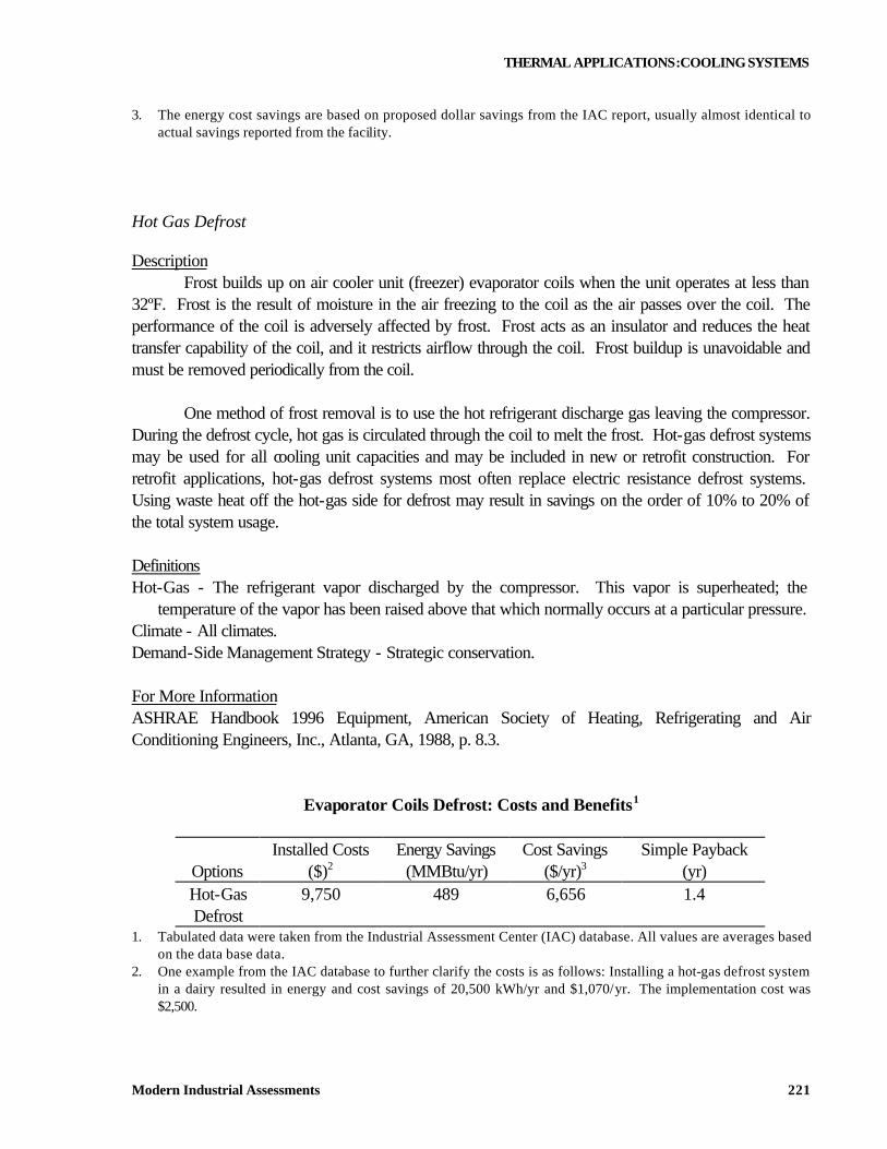
Evaporator Coils Defrost: Costs and Benefits1
Installed Costs Energy Savings Cost Savings Simple Payback
Options ($)2 (MMBtu/yr) ($/yr)3 (yr) Hot-Gas 9,750 489 6,656 1.4 Defrost
1. Tabulated data were taken from the Industrial Assessment Center (IAC) database. All values are averages based on the data base data.
2. One example from the IAC database to further clarify the costs is as follows: Installing a hot-gas defrost system in a dairy resulted in energy and cost savings of 20,500 kWh/yr and $1,070/yr. The implementation cost was $2,500.
THERMAL APPLICATIONS:ABSORPTION REFRIGERATION
Modern Industrial Assessments 222
4. The energy cost savings are based on proposed dollar savings from the IAC report, usually almost identical to actual savings reported from the facility.
7.2. ABSORPTION REFRIGERATION
Packaged absorption liquid chillers are used to produce chilled liquid for air-conditioning and industrial refrigeration processes. The chillers are usually powered by low-pressure steam or hot water, which can be supplied by the plant boiler or by waste heat from a process. Where prime energy is needed, mechanical refrigeration is usually preferable. Conditions favorable to absorption refrigeration are where sources of waste heat are available. 7.2.1. Operation
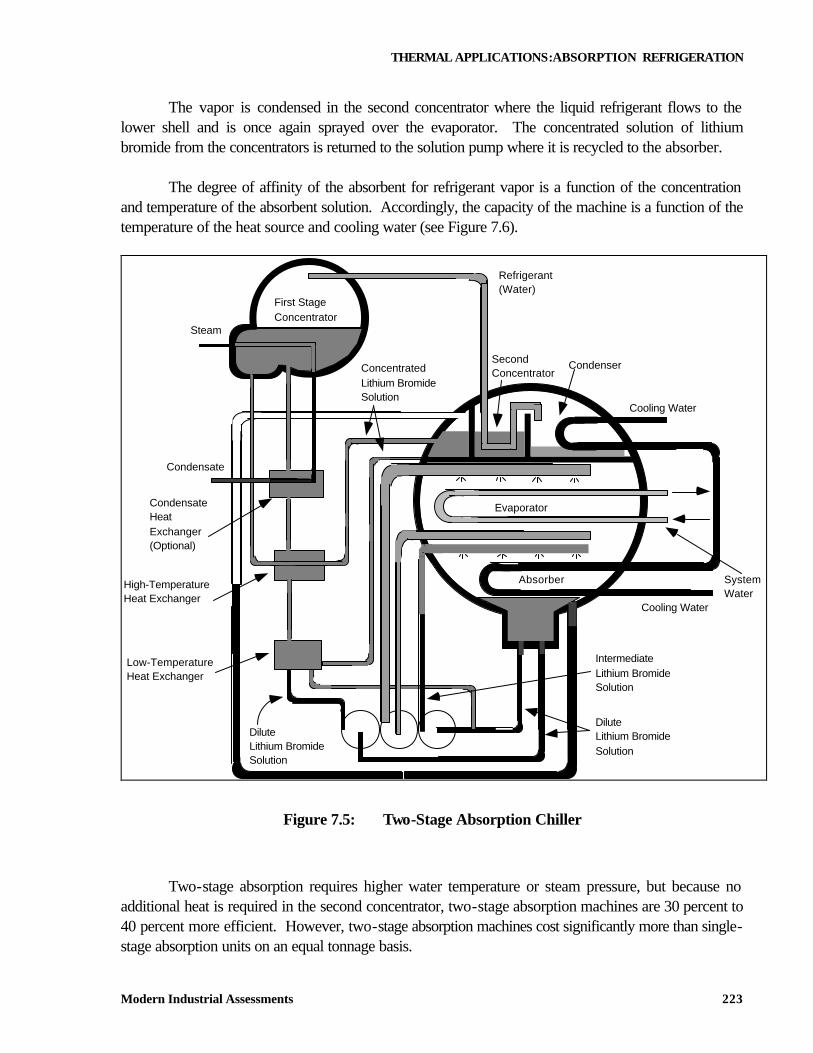
In the absorption cycle, two distinct chemicals are used and the cycle is driven by heat. The most common absorption system fluids are water as the volatile fluid and lithium bromide brine as the absorber fluid. Figure 7.5 illustrates the operation of a two-stage absorption chiller. Refrigerant enters the top of the lower shell from the condenser section and mixes with refrigerant being supplied from the refrigerant pump. Here the liquid sprays over the evaporator bundle. Due to the low vacuum (6 mm Hg) some of the refrigerant liquid vaporizes, cooling the refrigerant water to a temperature that corresponds closely to the shell pressure. As the refrigerant vapor/liquid migrates to the bottom half of the shell, a concentrated solution of liquid bromide is sprayed into the flow of descending refrigerant. The hygroscopic action between lithium bromide (a salt with an especially strong attraction for water) and water--and the related changes in concentration and temperature--result in the extreme vacuum in the evaporator directly above. Dissolving lithium bromide in water also gives off heat which is removed by the cooling water. The resultant dilute lithium bromide solution collects in the bottom of the absorber where it flows down to the solution pump. The dilute mixture of lithium bromide and refrigerant vapor is pumped through the heat exchangers, where it is preheated by a hot, concentrated solution from the concentrators (generators). The solution then flows to the first-stage concentrator where it is heated by an external heat source of steam or hot water. The condenser water used in the absorber and the condenser is normally returned to a cooling tower.
THERMAL APPLICATIONS:ABSORPTION REFRIGERATION
Modern Industrial Assessments 223
The vapor is condensed in the second concentrator where the liquid refrigerant flows to the lower shell and is once again sprayed over the evaporator. The concentrated solution of lithium bromide from the concentrators is returned to the solution pump where it is recycled to the absorber. The degree of affinity of the absorbent for refrigerant vapor is a function of the concentration and temperature of the absorbent solution. Accordingly, the capacity of the machine is a function of the temperature of the heat source and cooling water (see Figure 7.6).
Evaporator
Absorber
Condenser
Cooling Water
SystemWater
Refrigerant(Water)
SecondConcentrator
IntermediateLithium BromideSolution
DiluteLithium BromideSolution
DiluteLithium BromideSolution
High-TemperatureHeat Exchanger
Low-TemperatureHeat Exchanger
CondensateHeatExchanger(Optional)
Condensate
Steam
First StageConcentrator
ConcentratedLithium BromideSolution
Cooling Water
Figure 7.5: Two-Stage Absorption Chiller
Two-stage absorption requires higher water temperature or steam pressure, but because no additional heat is required in the second concentrator, two-stage absorption machines are 30 percent to 40 percent more efficient. However, two-stage absorption machines cost significantly more than single-stage absorption units on an equal tonnage basis.
THERMAL APPLICATIONS:ABSORPTION REFRIGERATION
Modern Industrial Assessments 224
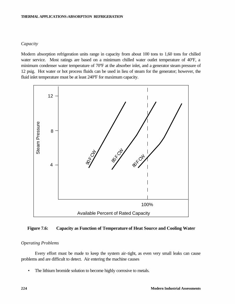
Capacity
Modern absorption refrigeration units range in capacity from about 100 tons to 1,60 tons for chilled water service. Most ratings are based on a minimum chilled water outlet temperature of 40ºF, a minimum condenser water temperature of 70ºF at the absorber inlet, and a generator steam pressure of 12 psig. Hot water or hot process fluids can be used in lieu of steam for the generator; however, the fluid inlet temperature must be at least 240ºF for maximum capacity.
12
8
4
100%
Available Percent of Rated Capacity
Ste
am P
ress
ure
90 F
CW
85 F
CW
80 F
CW
Figure 7.6: Capacity as Function of Temperature of Heat Source and Cooling Water
Operating Problems
Every effort must be made to keep the system air-tight, as even very small leaks can cause problems and are difficult to detect. Air entering the machine causes
• The lithium bromide solution to become highly corrosive to metals.
THERMAL APPLICATIONS:ABSORPTION REFRIGERATION
Modern Industrial Assessments 225
• The lithium bromide solution to crystallize. • The chilled water temperature to increase. • Refrigeration capacity to decrease.
Crystallization occurs when the lithium bromide solution does not go through the normal dilution cycle. When this happens, the solution becomes so concentrated that it crystallizes and plugs the solution lines. The unit must then be shut down and decrystallized. Crystallization can be caused by a power failure, controller malfunction, extreme variations in the condenser water temperature, or operator error in inadvertently allowing air to enter the machine. It is indicated by a rise in the outlet chilled-water temperature, a loss of solution pump (or a noisy solution pump), a loss of solution level in the absorber, and generator flooding. Although absorption refrigeration machines are generally more difficult to operate and require more maintenance than reciprocating and centrifugal machines, they allow waste stream to be utilized more efficiently and in the proper application can result in substantial energy savings.
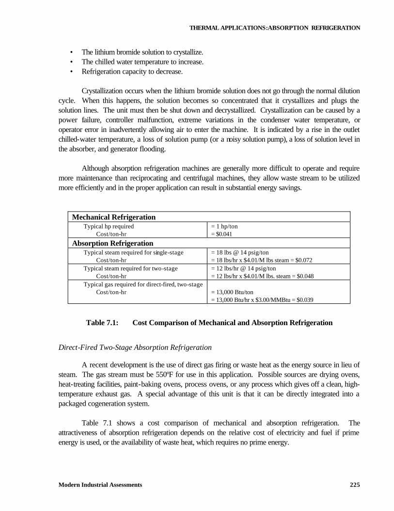
Mechanical Refrigeration Typical hp required
Cost/ton-hr = 1 hp/ton = $0.041
Absorption Refrigeration Typical steam required for single-stage
Cost/ton-hr = 18 lbs @ 14 psig/ton = 18 lbs/hr x $4.01/M lbs steam = $0.072
Typical steam required for two-stage Cost/ton-hr
= 12 lbs/hr @ 14 psig/ton = 12 lbs/hr x $4.01/M lbs. steam = $0.048
Typical gas required for direct-fired, two-stage Cost/ton-hr
= 13,000 Btu/ton = 13,000 Btu/hr x $3.00/MMBtu = $0.039
Table 7.1: Cost Comparison of Mechanical and Absorption Refrigeration
Direct-Fired Two-Stage Absorption Refrigeration
A recent development is the use of direct gas firing or waste heat as the energy source in lieu of steam. The gas stream must be 550ºF for use in this application. Possible sources are drying ovens, heat-treating facilities, paint-baking ovens, process ovens, or any process which gives off a clean, high-temperature exhaust gas. A special advantage of this unit is that it can be directly integrated into a packaged cogeneration system. Table 7.1 shows a cost comparison of mechanical and absorption refrigeration. The attractiveness of absorption refrigeration depends on the relative cost of electricity and fuel if prime energy is used, or the availability of waste heat, which requires no prime energy.
THERMAL APPLICATIONS:MECHANICAL REFRIGERATION
Modern Industrial Assessments 226
With the unit costs selected for the manual, the two-stage absorption system is slightly more costly to operate than mechanical refrigeration. Where waste heat can be utilized, absorption refrigeration is, of course, the obvious choice. In considering the use of waste heat for absorption refrigeration, it is worth a reminder that the first step should be to determine whether reducing or eliminating the waste heat is possible. A common application is the use of absorption refrigeration to utilize steam vented to atmosphere. However, in most cases a thorough study of the steam system will identify means of balancing the system to eliminate the loss of steam. 7.3. MECHANICAL REFRIGERATION
Refrigeration machines provide chilled water or other fluid for both process and air conditioning needs. Of the three basic types of refrigeration systems (mechanical compression, steam jet, and absorption), mechanical compression is the type generally used. The energy requirements of the steam jet refrigeration unit are high when compared with those for mechanical compression; therefore, the use of steam jet refrigeration is limited to applications having very low cost steam at 125 psig, a low condenser water cost, and a high electrical cost. With today’s energy costs, this type of system is rarely economical. 7.3.1. Mechanical Compression
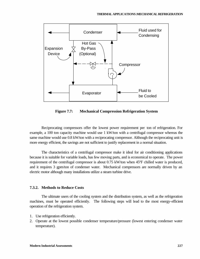
The mechanical compression refrigeration system consists of four basic parts; compressor, condenser, expansion device, and evaporator. The basic system is shown in Figure 7.7. A refrigerant, with suitable characteristics, is circulated within the system. Low-pressure liquid refrigerant is evaporated in the evaporator (cooler), thereby removing heat from the warmer fluid being cooled. The low-pressure refrigerant vapor is compressed to a higher pressure and a correspondingly higher saturation temperature. This higher pressure and temperature vapor is condensed in the condenser by a cooler medium such as cooling tower water, river water, city water, or outdoor air. The higher pressure and temperature refrigerant liquid is then reduced in pressure by an expansion device for delivery to the evaporator.
THERMAL APPLICATIONS:MECHANICAL REFRIGERATION
Modern Industrial Assessments 227
Hot GasBy-Pass
(Optional)
Fluid used forCondensing
Condenser
EvaporatorFluid tobe Cooled
ExpansionDevice
Compressor
Figure 7.7: Mechanical Compression Refrigeration System
Reciprocating compressors offer the lowest power requirement per ton of refrigeration. For example, a 100 ton capacity machine would use 1 kW/ton with a centrifugal compressor whereas the same machine would use 0.8 kW/ton with a reciprocating compressor. Although the reciprocating unit is more energy efficient, the savings are not sufficient to justify replacement in a normal situation. The characteristics of a centrifugal compressor make it ideal for air conditioning applications because it is suitable for variable loads, has few moving parts, and is economical to operate. The power requirement of the centrifugal compressor is about 0.75 kW/ton when 45ºF chilled water is produced, and it requires 3 gpm/ton of condenser water. Mechanical compressors are normally driven by an electric motor although many installations utilize a steam turbine drive. 7.3.2. Methods to Reduce Costs
The ultimate users of the cooling system and the distribution system, as well as the refrigeration machines, must be operated efficiently. The following steps will lead to the most energy-efficient operation of the refrigeration system. 1. Use refrigeration efficiently. 2. Operate at the lowest possible condenser temperature/pressure (lowest entering condenser water
temperature).
THERMAL APPLICATIONS:MECHANICAL REFRIGERATION
Modern Industrial Assessments 228
3. Operate at the highest possible evaporator temperature/pressure (highest leaving chilled-water temperature); do not overcool.
4. Operate multiple compressors economically. 5. Recover heat rejected in the condenser. 6. Use a hot gas bypass only when necessary. Use Refrigeration Efficiently
The most direct saving will obviously result from shutting down the equipment when refrigeration is not required. Short of shutting down equipment, the refrigeration load may be reduced by ensuring the cooling medium is utilized efficiently at the point of use. A typical problem is overcooling. Other unnecessary losses are inadequate insulation or poor operating practices such as simultaneous heating and cooling. A reduction in refrigeration load will, of course, reduce the operation of the refrigeration machines, including the associated pumps and cooling towers. Economizer cycles on air conditioning units will also permit early shutdown of refrigeration machines. Refer to the HVAC section for details of economizer cycle operation. Reduce the Condensing Temperature (Pressure)
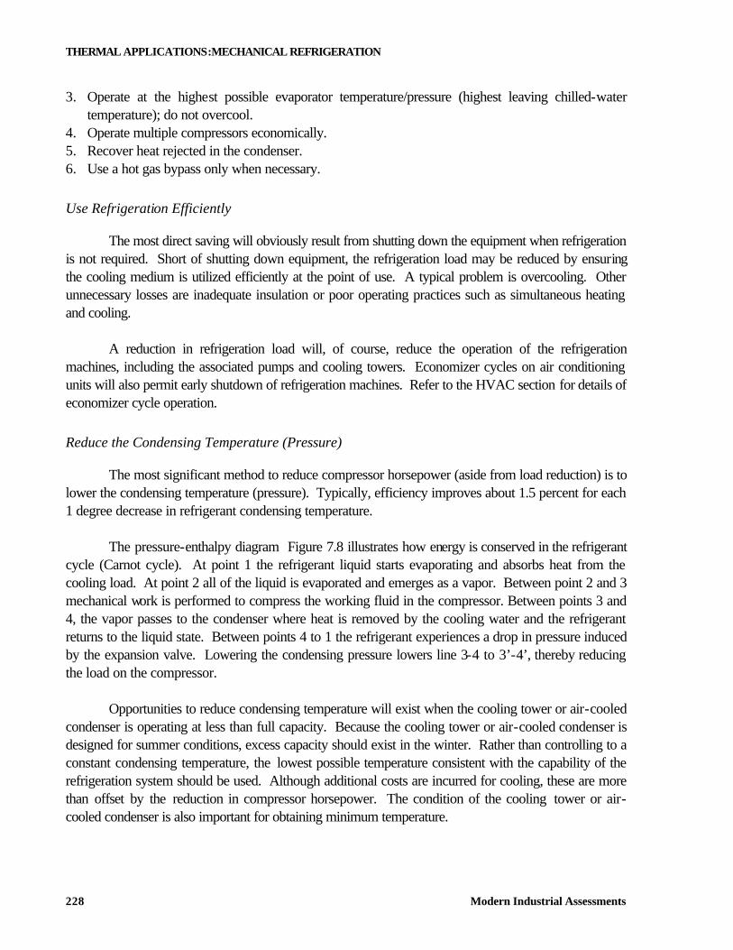
The most significant method to reduce compressor horsepower (aside from load reduction) is to lower the condensing temperature (pressure). Typically, efficiency improves about 1.5 percent for each 1 degree decrease in refrigerant condensing temperature. The pressure-enthalpy diagram Figure 7.8 illustrates how energy is conserved in the refrigerant cycle (Carnot cycle). At point 1 the refrigerant liquid starts evaporating and absorbs heat from the cooling load. At point 2 all of the liquid is evaporated and emerges as a vapor. Between point 2 and 3 mechanical work is performed to compress the working fluid in the compressor. Between points 3 and 4, the vapor passes to the condenser where heat is removed by the cooling water and the refrigerant returns to the liquid state. Between points 4 to 1 the refrigerant experiences a drop in pressure induced by the expansion valve. Lowering the condensing pressure lowers line 3-4 to 3’-4’, thereby reducing the load on the compressor. Opportunities to reduce condensing temperature will exist when the cooling tower or air-cooled condenser is operating at less than full capacity. Because the cooling tower or air-cooled condenser is designed for summer conditions, excess capacity should exist in the winter. Rather than controlling to a constant condensing temperature, the lowest possible temperature consistent with the capability of the refrigeration system should be used. Although additional costs are incurred for cooling, these are more than offset by the reduction in compressor horsepower. The condition of the cooling tower or air-cooled condenser is also important for obtaining minimum temperature.
THERMAL APPLICATIONS:MECHANICAL REFRIGERATION
Modern Industrial Assessments 229
Enthalpy
Pre
ssur
e
Condensing (Heat removed fromrefrigerant in the condenser)
Liqu
id L
ine
Vap
or L
ine
Com
pres
sion
Exp
ansi
on
Evaporation (Heat added to therefrigerant in the evaporator)
Power inputcompression cycle
Lower condensing pressure
Higher evaporative (suction) pressure
1 2
34
1' 2'
3'4'
Figure 7.8: Pressure-Enthalpy Diagram
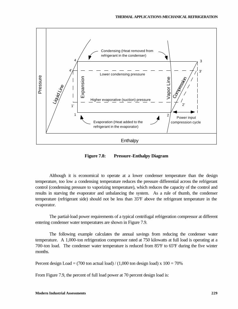
Although it is economical to operate at a lower condenser temperature than the design temperature, too low a condensing temperature reduces the pressure differential across the refrigerant control (condensing pressure to vaporizing temperature), which reduces the capacity of the control and results in starving the evaporator and unbalancing the system. As a rule of thumb, the condenser temperature (refrigerant side) should not be less than 35ºF above the refrigerant temperature in the evaporator. The partial-load power requirements of a typical centrifugal refrigeration compressor at different entering condenser water temperatures are shown in Figure 7.9. The following example calculates the annual savings from reducing the condenser water temperature. A 1,000-ton refrigeration compressor rated at 750 kilowatts at full load is operating at a 700-ton load. The condenser water temperature is reduced from 85ºF to 65ºF during the five winter months. Percent design Load = (700 ton actual load) / (1,000 ton design load) x 100 = 70% From Figure 7.9, the percent of full load power at 70 percent design load is:
THERMAL APPLICATIONS:MECHANICAL REFRIGERATION
Modern Industrial Assessments 230
At 85ºF condenser water, 65.5 percent At 65ºF condenser water, 60.0 percent Input kW at 85ºF condenser water = 750 x 65.6% = 491 Input kW at 65ºF condenser water = 750 x 60.0% = 450 Savings = 41 kW Annual Savings = 41 kW x 6,000 hrs/yr x 5 mos/12 x 0.05 $/kWh = $5,130
Pe rce n t o f D e sign Load
0
10
20
30
40
50
60
70
80
90
100
0 20 40 60 80 100
85 F
75 F
65 F
55 F
Condenser in let
wat er t emp.
Figure 7.9: Partial Load Requirement for Centrifugal Refrigeration Compressors
Closely related to lower cooling water temperature is proper maintenance of the condensers. Inadequate water treatment can lead to scaling which can decrease heat transfer through the heat exchanger tubes. A gradual increase in refrigerant temperature at constant load conditions is an early signal of condenser tube fouling.
THERMAL APPLICATIONS:MECHANICAL REFRIGERATION
Modern Industrial Assessments 231
Raise the Evaporator Temperature (Pressure)
An increase in evaporator temperature reduces the energy required by the refrigeration machine because it must perform less work (reduced lift) per ton of refrigeration produced. The amount of energy reduction depends on the type of refrigeration machine. For a centrifugal machine, the reduction is approximately 1 to 1.5 percent for each degree the evaporator temperature increases. As shown in Figure 7.8 increasing the evaporator temperature raises line 1-2 to 1’-2’, thereby reducing the load on the compressor between points 2 and 3. The effect is the same as reducing the compressor load by a reduction in condensing pressure (temperature) described in the previous method. Consult the actual performance curve for the individual machine for a more accurate estimate of horsepower reduction. In some cases a higher evaporator temperature may not be possible if it is fixed by production requirements. An opportunity to increase the evaporator temperature (chilled water temperature) will exist when the flow of chilled water to the various areas is throttled. The throttle condition indicates that less than full design flow is required by the units to satisfy the load. The chilled-water temperature can be increased until it reaches the point at which any single user is requiring close to full flow. The system temperature will be controlled by the single user that first reaches full capacity. While some reduction in compressor power is obtained by increasing the leaving chilled-water temperature, greater savings are possible with a centrifugal compressor by changing the compressor speed. The reason is that, at a constant speed, the chilled-water temperature is raised by closing the prerotation vanes on the compressor. This causes the reduction in power to be less than expected for the corresponding increase in evaporating temperature. The speed change could be accomplished by changing gears; or if a variable chilled-water temperature is appropriate, a variable-speed drive could be considered. To find the savings from an increase in the chilled-water temperature from 45ºF to 50ºF, use the following example. The refrigeration machine is rated at 1,000 tons and operates at an average load of 600 tons for five months per year.
Conditions: input = 412 kW; 1,800 gpm condenser water Annual Savings = 412 kW x (50ºF - 45ºF) x 1% x 6,000 hrs/yr x 5 mos/12 x $0.05/kWh = $2,580
Note that the condenser water flow does not change. Operate Multiple Compressors Economically
If an installation has multiple refrigeration units, economic operation of these units can reduce energy consumption. The operating characteristics of the types of compressors used will determine the
THERMAL APPLICATIONS:MECHANICAL REFRIGERATION
Modern Industrial Assessments 232
economical mode of operation. The power requirements of reciprocating compressors make their operation more efficient if one compressor is unloaded or shut down before a second compressor is unloaded. On the other hand, the partial load requirements of a centrifugal compressor, as shown in Figure 7.9 make it more economical to operate two compressors at equal partial load than one compressor at full load and the second at low load. For example, it is more economical to operate two centrifugal compressors at 80 percent of capacity than one at 100 percent and the second at 60 percent. The same approach can be used in the assignment of refrigeration machines to cooling equipment. It is important that the capacity of the refrigeration machine match the capacity of the cooling unit(s) it serves. Therefore, in a system of multiple refrigeration machines and cooling units, care must be taken to assign the refrigeration machines to the cooling units correctly. Where two or more refrigeration machines supply separate chilled water systems and are located in close proximity to each other, interconnection of the chilled water systems can be considered. With this modification, during periods of light loads one machine may be able to carry the load for more than one system. The following example illustrates the savings from operating two compressors equally loaded, based on five months per year operation. One centrifugal compressor rated at 1,000 tons, 750 kilowatts, and 85ºF entering condenser water temperature is operating at a 900-ton load and 75ºF entering condenser water. A second 1,000-ton compressor is not running. From Figure 7.9 you can see the percent of full-load power at 75ºF entering condenser water is:
At 90 percent design load, 84.0 percent At 45 percent design load, 40.5 percent Input kW at 900 tons = 750 kW x 84% = 630 Input kW (two units at 450 tons each) = 750 kW x 40.5% x 2 compressors = 608 Savings = 22 kW Annual Savings = 22 kW x 6,000 hrs/yr x 5 mos/12 x $0.05/kWh = $2,750
Recover Heat
A majority of the time, heat rejected from a condenser can be recovered. The amount of heat rejected in the condenser is 12,000 Btu per hour plus the heat of compression (about 2,500 Btu/hr per ton), giving a total heat rejection of 14,500 Btu/hr per ton produced.
THERMAL APPLICATIONS:MECHANICAL REFRIGERATION
Modern Industrial Assessments 233
The use of a split condenser permits partial recovery of rejected heat. A split condenser uses two cooling water streams: a process stream that is preheated in the first condenser and cooling tower water for the second condenser. The preheating of a process stream reduces the heating load on the cooling tower. This heat recovery scheme is applicable only if the plant can use a low temperature heat source. In the following example, a mechanical compressor rated at 1,000 tons is operating five months a year at an average 600-ton load. The savings from recovering 50 percent of the rejected heat to preheat water now heated by a steam hot water heater are:
Heat Rejected = 600 tons x 14,500 Btu/ton-hr = 8,700,000 Btu/hr Annual Savings = 8,700,000 Btu/hr x 50% x 6,000 hrs/yr x 5 mos/12 x $4.24 / 106 Btu = $46,100
Reduce Operation of Hot-Gas Bypass
On mechanical refrigeration machines, the primary elements for load controls are the suction damper, or vanes, and the hot-gas bypass which prevents compressor surge at low loads. The suction vanes are used to throttle refrigerant gas flow to the compressor within the area of stable compressor operation. As load or flow drops, where it approaches the compressor surge point, the hot-gas bypass is opened to maintain constant gas flow through the compressor. Below this load point for the hot-gas bypass, compressor flow, suction, and discharge conditions remain fairly constant, so that power consumption is nearly constant. Obviously, opening the hot-gas bypass too soon, or having a leaking hot-gas bypass valve, will increase operating cost (kilowatts per ton). It is not uncommon to find the bypass controls taken out of service, with the bypass set to maintain a fixed opening and constantly recycle high-pressure refrigerant vapors to the suction side of the compressor. A second frequent deficiency occurs when the hot-gas bypass is faulty or grossly oversized and is leaking through. A third source of energy loss is faulty load control, which can cause improper operation of the hot-gas bypass valve. Considerable energy can be saved and capacity recouped if the defective hot-gas bypass valves and their controls are corrected. Optimize Refrigeration Performance
The most basic approach to reducing refrigeration costs is to ensure that the units are operating at maximum efficiency. To monitor performance, each refrigeration machine must have proper instrumentation. This instrumentation includes flowmeters for both the chilled water and the condenser
THERMAL APPLICATIONS:INSULATION
Modern Industrial Assessments 234
water, pressure gauges at the inlet and outlet of both the condenser and evaporator, and temperature wells in both the inlet and outlet of the condenser and the evaporator. These temperature wells should be located in such a manner that a liquid can be placed in the well. The temperature measuring device used to test the equipment should read accurately to one-tenth of a degree. 7.4. INSULATION
Although generally not viewed as a part of the mechanical design system, insulation is an important part of every plant or building where any transfer of fluids or gases takes place and the their temperature is required to be different then that of ambient air. Properly insulated pipes, tanks and other equipment can save thousands of dollars. 7.4.1. Introduction
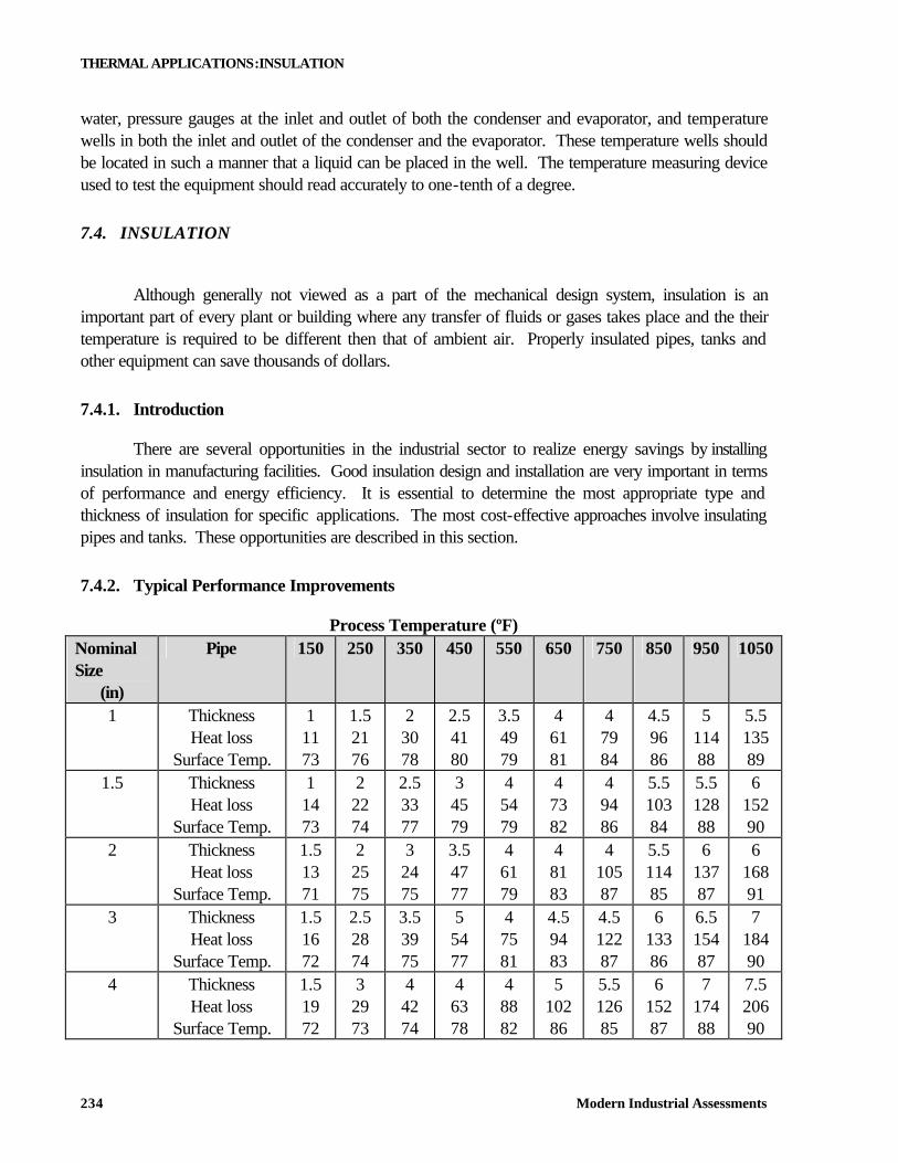
There are several opportunities in the industrial sector to realize energy savings by installing insulation in manufacturing facilities. Good insulation design and installation are very important in terms of performance and energy efficiency. It is essential to determine the most appropriate type and thickness of insulation for specific applications. The most cost-effective approaches involve insulating pipes and tanks. These opportunities are described in this section. 7.4.2. Typical Performance Improvements
Process Temperature (ºF) Nominal Size
(in)
Pipe 150 250 350 450 550 650 750 850 950 1050
1 Thickness Heat loss
Surface Temp.
1 11 73
1.5 21 76
2 30 78
2.5 41 80
3.5 49 79
4 61 81
4 79 84
4.5 96 86
5 114 88
5.5 135 89
1.5 Thickness Heat loss
Surface Temp.
1 14 73
2 22 74
2.5 33 77
3 45 79
4 54 79
4 73 82
4 94 86
5.5 103 84
5.5 128 88
6 152 90
2 Thickness Heat loss
Surface Temp.
1.5 13 71
2 25 75
3 24 75
3.5 47 77
4 61 79
4 81 83
4 105 87
5.5 114 85
6 137 87
6 168 91
3 Thickness Heat loss
Surface Temp.
1.5 16 72
2.5 28 74
3.5 39 75
5 54 77
4 75 81
4.5 94 83
4.5 122 87
6 133 86
6.5 154 87
7 184 90
4 Thickness Heat loss
Surface Temp.
1.5 19 72
3 29 73
4 42 74
4 63 78
4 88 82
5 102 86
5.5 126 85
6 152 87
7 174 88
7.5 206 90
THERMAL APPLICATIONS:INSULATION
Modern Industrial Assessments 235
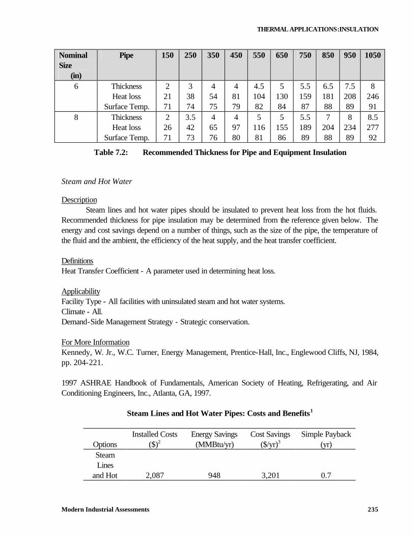
Nominal Size
(in)
Pipe 150 250 350 450 550 650 750 850 950 1050
6 Thickness Heat loss
Surface Temp.
2 21 71
3 38 74
4 54 75
4 81 79
4.5 104 82
5 130 84
5.5 159 87
6.5 181 88
7.5 208 89
8 246 91
8 Thickness Heat loss
Surface Temp.
2 26 71
3.5 42 73
4 65 76
4 97 80
5 116 81
5 155 86
5.5 189 89
7 204 88
8 234 89
8.5 277 92
Table 7.2: Recommended Thickness for Pipe and Equipment Insulation Steam and Hot Water
Description Steam lines and hot water pipes should be insulated to prevent heat loss from the hot fluids. Recommended thickness for pipe insulation may be determined from the reference given below. The energy and cost savings depend on a number of things, such as the size of the pipe, the temperature of the fluid and the ambient, the efficiency of the heat supply, and the heat transfer coefficient. Definitions Heat Transfer Coefficient - A parameter used in determining heat loss. Applicability Facility Type - All facilities with uninsulated steam and hot water systems. Climate - All. Demand-Side Management Strategy - Strategic conservation. For More Information Kennedy, W. Jr., W.C. Turner, Energy Management, Prentice-Hall, Inc., Englewood Cliffs, NJ, 1984, pp. 204-221. 1997 ASHRAE Handbook of Fundamentals, American Society of Heating, Refrigerating, and Air Conditioning Engineers, Inc., Atlanta, GA, 1997.
Steam Lines and Hot Water Pipes: Costs and Benefits1
Installed Costs Energy Savings Cost Savings Simple Payback Options ($)2 (MMBtu/yr) ($/yr)3 (yr) Steam Lines
and Hot 2,087 948 3,201 0.7
THERMAL APPLICATIONS:INSULATION
Modern Industrial Assessments 236
Water Pipes
1. Tabulated data were taken from the Industrial Assessment Center (IAC) database. All values are averages based on the data base data. The implementation rate for this measure was 68%.
2. One example from the IAC data base to further clarify the costs is as follows: Insulating 500 ft of condensate return pipes located throughout a plant having a 300 MMBtu/hr steam boiler resulted in energy savings of 370 MMBtu/yr and a cost savings of $960/yr. The implementation cost was $1,920.
3. The energy cost savings are based on proposed dollar savings from the IAC report , usually almost identical to actual savings reported from the facility.
Cold Water
Description Lines containing chilled water should be insulated to prevent condensation and frost buildup on the lines and to prevent heat gain. Condensation will occur whenever moist air comes into contact with a surface that is at a temperature lower than the dew point of the vapor. In addition, heat gained by uninsulated chilled water lines can adversely affect the efficiency of a cooling system. Definitions Chilled Water - Water that is cooled by a chiller. It is usually used for process cooling in industrial
applications. Applicability Facility Type - All facilities having uninsulated chilled water lines. Climate - All. Demand-Side Management Strategy - Strategic conservation. For More Information Industrial Assessment Center (IAC). Contact the IAC nearest to your area.
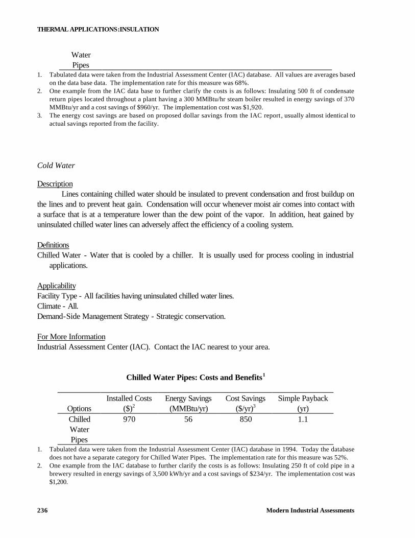
Chilled Water Pipes: Costs and Benefits1
Installed Costs Energy Savings Cost Savings Simple Payback Options ($)2 (MMBtu/yr) ($/yr)3 (yr) Chilled 970 56 850 1.1 Water Pipes
1. Tabulated data were taken from the Industrial Assessment Center (IAC) database in 1994. Today the database does not have a separate category for Chilled Water Pipes. The implementation rate for this measure was 52%.
2. One example from the IAC database to further clarify the costs is as follows: Insulating 250 ft of cold pipe in a brewery resulted in energy savings of 3,500 kWh/yr and a cost savings of $234/yr. The implementation cost was $1,200.
THERMAL APPLICATIONS:INSULATION
Modern Industrial Assessments 237
3. The energy cost savings are based on actual dollar savings as reported to IAC from the facility. 7.4.3. Insulation of Tanks
Tanks, similar to pipes, should be properly insulated if their purpose is to hold media at certain temperatures, especially for prolonged periods of time. Hot Media
Description Often, tanks containing hot fluids in manufacturing operations lack adequate insulation. The tanks may be insulated with blanket type flexible insulation (1 in. thick, 1.5 lb density) or rigid insulation, depending on the type of tank. The savings would increase as the boiler efficiency decreases. The savings would also increase as the temperature in the tank increases. Definitions Condensate - The hot water that is the steam after it has cooled and consequently condensed. Applicability Facility Type - All facilities. Climate - All. Demand-Side Management Strategy - Strategic conservation.
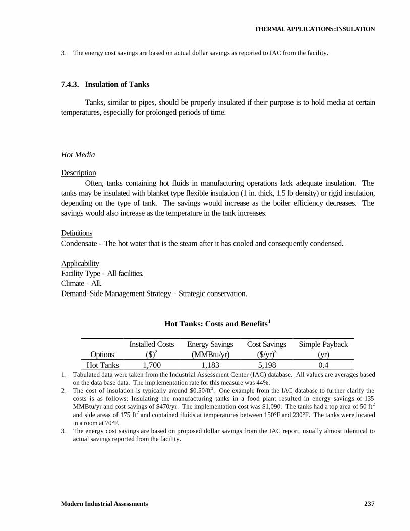
Hot Tanks: Costs and Benefits1
Installed Costs Energy Savings Cost Savings Simple Payback Options ($)2 (MMBtu/yr) ($/yr)3 (yr)
Hot Tanks 1,700 1,183 5,198 0.4 1. Tabulated data were taken from the Industrial Assessment Center (IAC) database. All values are averages based
on the data base data. The imp lementation rate for this measure was 44%. 2. The cost of insulation is typically around $0.50/ft2. One example from the IAC database to further clarify the
costs is as follows: Insulating the manufacturing tanks in a food plant resulted in energy savings of 135 MMBtu/yr and cost savings of $470/yr. The implementation cost was $1,090. The tanks had a top area of 50 ft2 and side areas of 175 ft2 and contained fluids at temperatures between 150°F and 230°F. The tanks were located in a room at 70°F.
3. The energy cost savings are based on proposed dollar savings from the IAC report, usually almost identical to actual savings reported from the facility.
THERMAL APPLICATIONS:INSULATION
Modern Industrial Assessments 238
Cold Media
Description Uninsulated tanks containing cold fluids are occasionally found in applications, such as chilled water tanks that are located in areas where there can be considerable heat gain through the tank surfaces. If the air surrounding the tank is at a higher temperature than that of the tank, heat will be transferred to the contents of the tank. By insulating these tanks, the heat transfer and load on the system will be reduced, resulting in significant energy savings. Definitions Coefficient of Performance (COP) - The ratio between thermal energy out of and electrical energy into
the system. Applicability Facility Type - Any facility having uninsulated cold tanks and significant operating hours. Climate - All. Demand-Side Management Strategy - Strategic conservation. For More Information 1989 ASHRAE Handbook of Fundamentals, American Society of Heating, Refrigerating, and Air Conditioning Engineers, Inc., Atlanta, GA, 1989, Ch. 22.
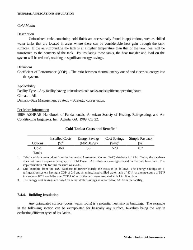
Cold Tanks: Costs and Benefits1
Installed Costs Energy Savings Cost Savings Simple Payback Options ($)2 (MMBtu/yr) ($/yr)3 (yr)
Cold Tanks
460 36 520 0.7
1. Tabulated data were taken from the Industrial Assessment Center (IAC) database in 1994. Today the database does not have a separate category for Cold Tanks. All values are averages based on the data base data. The implementation rate for this measure was 54%.
2. One example from the IAC database to further clarify the costs is as follows: The energy savings on a refrigeration system having a COP of 2.0 and an uninsulated chilled water tank of 47 ft2 at a temperature of 52°F in a room at 85°F would be over 2636 kWh/yr if the tank were insulated with 1 in. fiberglass.
3. The energy cost savings are based on actual dollar savings as reported to IAC from the facility. 7.4.4. Building Insulation
Any uninsulated surface (doors, walls, roofs) is a potential heat sink in buildings. The example in the following section can be extrapolated for basically any surface, R-values being the key in evaluating different types of insulation.
THERMAL APPLICATIONS:INSULATION
Modern Industrial Assessments 239
Dock Doors
Description Uninsulated dock doors can be a source of significant heat loss in manufacturing facilities. The doors can often be insulated by installing styrofoam or fiberglass in the door panels. The savings depend on the size of the doors, the efficiency of the heating system, the R-values of the insulated and uninsulated doors, and the number of degree heating hours per year. Definitions Degree Heating Hours - A measure relating ambient temperature to heating energy required. If the
outside temperature is 1 degree below the base temperature in the plant for 1 hour then that represents 1 degree heating hour.
R-Value - Measure of resistance to heat transfer in Btu/hr-ft2-ºF. Applicability Facility Type - All facilities with overhead doors. Climate - Any climate in which heating is required. Demand-Side Management Strategy - Strategic conservation. For More Information 1997 ASHRAE Handbook of Fundamentals, American Society of Heating, Refrigerating, and Air Conditioning Engineers, Inc., Atlanta, GA.
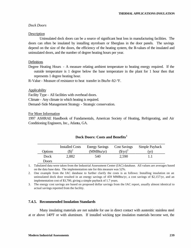
Dock Doors: Costs and Benefits1
Installed Costs Energy Savings Cost Savings Simple Payback Options ($)2 (MMBtu/yr) ($/yr)3 (yr) Dock Doors
2,882 540 2,590 1.1
1. Tabulated data were taken from the Industrial Assessment Center (IAC) database. All values are averages based on the data base data. The implementation rate for this measure was 52%.
2. One example from the IAC database to further clarify the costs is as follows: Installing insulation on an uninsulated dock door resulted in an energy savings of 459 MMBtu/yr, a cost savings of $2,157/yr, and an implementation cost of $3,700, giving a simple payback of 1.7 years.
3. The energy cost savings are based on proposed dollar savings from the IAC report, usually almost identical to actual savings reported from the facility.
7.4.5. Recommended Insulation Standards
Many insulating materials are not suitable for use in direct contact with austenitic stainless steel at or above 140ºF or with aluminum. If installed wicking type insulation materials become wet, the
THERMAL APPLICATIONS:INSULATION
Modern Industrial Assessments 240
soluble ingredients leach out and deposit on the surface of the metal substrate. The deposited ingredients usually consist of sodium silicate (if insulation has been inhibited) and chlorides and alkalites. The chlorides in these deposits can cause stress corrosion cracking of austenitic stainless steel at temperatures above 140ºF if there is not enough sodium silicate inhibitor to neutralize them. Alkaline ingredients in insulation, when wet, can cause corrosion of unprotected aluminum substrate. Where aluminum substrate protection is required, fibrated asphalt cutback should be included in the installation cost. Excess wetting with water or especially with acid solution can substantially reduce the service life of the inhibitor. Wet insulation can corrode unprotected carbon steel pipe and equipment, especially during storage or shutdown periods. Lowest Cost System
The lowest cost system recommended is based on both installed and continuing cost, consistent with reasonable safety and return on investment. In other words, the lowest cost thermal insulation system is one that will remain in place for the design life of the system and one that will provide the desired function. Most often, the options available might not be as trivial as one might suspect. Interruption of production must also be accounted for. Economic Factors to be Considered in Basic Insulation Selection
Glass Fiber Glass fiber insulation has the disadvantage of moisture absorption and low resistance to abuse. The continuing maintenance can offset any advantage of the initial cost. Calcium Silicate Calcium silicate and inhibited calcium silicate provide the lowest cost system in the temperature range between 300ºF and 1200ºF. They are also satisfactory down to 140ºF if polyisocyanurate foam is not suitable. Polyisocyanurate Polyisocyanurate foam is preferred to both glass fiber and calcium silicate for low temperature applications (140ºF to 300ºF). When compared with calcium silicate, polyisocyanurate has better moisture resistance which is particularly important for outdoor application. Material and installation costs are comparable with those for calcium silicate. Polyisocyanurate insulation is suitable over a temperature range of -100ºF to 300ºF and, therefore, is excellent for dual temperature applications. Mineral Wool Mineral wool provides the lowest cost system in the temperature range of 1200ºF to 1800ºF. This is true only if the metal surfaces to be insulated are not austenitic stainless steel and/or abuse resistance is not a factor.
THERMAL APPLICATIONS:INSULATION
Modern Industrial Assessments 241
Finish Factors Influencing Insulation Selection
Where allowed, the lowest initial-cost finish for pipe is kraft aluminum laminate. The finish is limited to dry, indoor, low-traffic areas, and may discolor with age. The lowest cost finish on a continuing basis for pipe and cylindrical sections of indoor or outdoor equipment, if chemical resistance is not an issue, is a smooth aluminum jacket fastened with stainless steel bands. Reinforced mastic finishes should be used only over irregular shapes and where absolutely necessary. Stainless steel pipe covering is recommended only in special situations where other finishes do not provide adequate protection. 7.4.6. Process Equipment
Insulating process equipment does not differ in principle from insulating tanks or pipes. The purpose is to maintain certain temperatures where required and minimize heat input to make up for heat transfer losses. Injection Mold Barrels
Description The barrels on injection molding machines are heated to a very high temperature so that the plastic will flow into the mold. The heat loss from the barrels contributes to the air conditioning load in the plant as well as increasing the energy required to keep the barrels hot. Rock wool blanket insulation is made specifically for this purpose and is easily removed if maintenance on the barrels is required. This measure is not recommended when ABS or PVC plastics are being molded because the shear forces generate so much heat that cooling is required. Definitions Barrels - The portion of an injection molding machine through which the molten plastic is forced by the
piston. Applicability Facility Type - Any injection molding facility. Climate - All. Demand-Side Management Strategy - Strategic conservation.
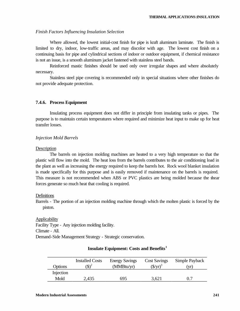
Insulate Equipment: Costs and Benefits1
Installed Costs Energy Savings Cost Savings Simple Payback Options ($)2 (MMBtu/yr) ($/yr)3 (yr) Injection
Mold 2,435 695 3,621 0.7
THERMAL APPLICATIONS:INSULATION
Modern Industrial Assessments 242
Barrels 1. Tabulated data were taken from the Industrial Assessment Center (IAC) database. All values are averages based
on the data base data. The implementation rate for this measure was 46%. 2. One example from the IAC database to further clarify the costs is as follows: Insulating injection mold barrels
resulted in an energy savings of 375 MMBtu/yr, a cost savings of $2,589, and an implementation cost of $2,028, giving a simple payback of ten months.
3. The energy cost savings are based on proposed dollar savings from the IAC report, usually almost identical to actual savings reported from the facility.
REFERENCES 1. Handisyde, C.C., and Melluish, D.J., Thermal Insulation of Buildings, HMSO, 1971 2. Malloy, J.F., Thermal Insulation, Van Nostrand Reinhold, 1969 3. The Association of Energy Engineers, Corporate Energy Management Manual, The Fairmont
Press, 1979 4. Thumann A., and Mehta D.P., Handbook of Energy Engineering, The Fairmont Press, 1992