6.solar fuel cell hybrid vehicle
DESCRIPTION
Solar Fuel cellTRANSCRIPT

Paper Title : HYBRID VEHICLES FOR 21st CENTURY
Authors Name : 1. GUNJAL SHIRISH S.
2. DHAMANE DEEPAK S.
Institution : SANJIVANI RURAL EDUCATION SOCIETY’SCOLLEGE OF ENGINEERING
KOPARGAON
Address : “SHIVANAND” ,Bharatnagar, maldad road
P. O. Sangamner, Dist. Ahmednagar
Pin. 422605 (M.S.)
Tel. No. : (02425) 228495
Email id : [email protected]

A
TECHNICAL PAPER PRESENTATION
HYBRID VEHICLES FOR 21 st
CENTURY
PAPER PRESENTED BY
Mr. GUNJAL SHIRISH.S. (B.E Mechanical)
Mr. DHAMANE DEEPAK S. (B.E. Mechanical)
SANJIVANI RURAL EDUCATION SOCIETY’SCOLLEGE OF ENGINEERING
KOPARGAON-423603.

ABSTRACT
Innovative thinking leads to development of new technologies.
Today, the world is facing serious pollution crisis due to the exhaust
gases from vehicles using petroleum-based fuel. The pollutants like
HC, NOx occurs due to the incomplete combustion of fuel. These
pollutants are very harmful to human being causing various diseases.
Also the fuel recourses are depleting rapidly.
Air pollution is the major problem that we face in our day to day
life. It is one of the most dangerous and common kind of
environmental pollution that is reported in most industrial towns and
metropoliton cities of India. The ever increasing vehicular traffic
produces a great threat to environment. There is a need for new
technology to tackle this problem and this paper deals with the
introduction of Solar and Fuel Cell Hybrid vehicle technology which
promises 100% pollution free.
Sr. No.
Title Page No.
1 INTRODUCTION 1
2 SOLAR RADIATION IN INDIA 2
3 SELECTION OF A VEHICLE. 3
4 CONVERSION OF ELECTRIC VEHICLE INTO A
SOLAR FUEL CELL HYBRID VEHICLE
5
5SOLAR ARRAY SIZE AND SELECTION
8
6 PHOTOVOLTAIC SYSTEM 10
7 CONCLUSION 11
BIBLIOGRAPHY12
CONTENTS

INTRODUCTION
The technology of hybrid vehicle is a new concept in the
engineering of Eco – friendly and highly efficient vehicles. The
technology is widely used in advanced countries like USA and
JAPAN for its best performance and low cost of maintenance and
antipollutive design.
Stainable energy supply in the fast growing world is facing
serious challenges on account of depleting fossil fuels and associated
environmental impacts.
Solar vehicle technology and fuel cell vehicle technology will be
an answer for the depleting fossil fuels and associated environmental
impacts.
The main objective of this paper is to visualize the new
technology of integrating a solar vehicle and fuel cell technology to
develop a new hybrid vehicle which is 100% Eco-friendly.
The hybrid system involving a battery and Fuel cell has been
considered. Battery takes care of the peak load demand while the
fuel cell is adequate for meeting the peak demand and charges the
battery simultaneously. Here the solar photo voltaic cells are placed
at the roof of the vehicle to provide the additional electrical energy to
propel the vehicle.
SOLAR RADIATION IN INDIA
It is said that the topical areas lying between the latitudes 30°N
and 30°S have at least 2000 hours of bright sunshine are ideal for
exploiting solar energy.
India lies between the latitude of 7°N and 37°N, and receives
an annual intensity of solar radiation between 16700-29260 kj/m2/day.
Therefore it is suitable to exploit solar hybrid technology in India.
Mean solar radiation in India is given in table 1.
Table 1 : Solar Radiation’s in selected cities in India
City MeanDelhi 655
Mumbai 701Calcutta 681Chennai 720Srinagar 631
Trivandrum 721

SELECTION OF A VEHICLE.
The specification of a typical battery vehicle developed in India is
given bellow.
Maximum vehicle speed = 75 kmph
Acceleration (0 to 50 kmph) = 14 mps2
Range per charge = 60 km at 45 kmph
Pay load = 10 Persons/800 kg
Dimension L = 5000mm
W = 2000mm
H =1800mm
Drive motor = 20 BHP/96V/3000rpm DC series Traction motor.
Propulsion Battery = 235Ah/96V Lead acid,
Tubular Plate traction batteries.
Controller = Electronic thyristor chopper
Controller with control and
Trip on motor overheating
Features.
Instrumentation = speedometer, odometer,
Charge indicator, voltmeter
Motor and battery voltage
Ammeter for motor current.

The above specification is taken for consideration purpose. The
above electric vehicle is converted into a solar fuel cell hybrid
vehicle.
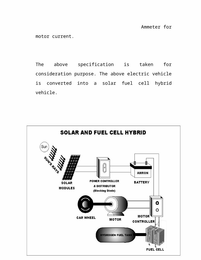
Fig.1 Layout of Solar Fuel Cell Hybrid vehicle.

CONVERSION OF THE ABOVE ELECTRIC VEHICLE
INTO A SOLAR FUEL CELL HYBRID VEHICLE
The layout of a Solar Fuel cell hybrid electric vehicle is shown in
the fig.1. The power required to propel the vehicle is 20 BHP
(96V/235AH), it is supplied by using four 24V/235AH batteries
connected in series combination. In addition to this a Hydrogen Fuel
cell unit with output of 96V/235amp is connected directly to the
electric motor with required control and protection units.
Of all the alternative vehicle propulsion drive system, the fuel
cell option offers the most promising out look for the future. Its
efficiency factor is twice that of the internal
combustion engines used in traditional automobiles. It is
entirely pollution free. The emission free and quite operation of fuel
cell-based cars offers a desired advantage over the air and noise
pollution. Hydrogen has great potential as a fuel. Hydrogen is
practically as an alternative fuel because there is no carbon in the
combustion process. So, carbon monoxide and carbon dioxide are
not produced. Fuel cells have a fairly simple sandwich-like structure.
The actual cell consists of three layers - anode, electrolyte and
cathode. Between two gas permeable electrodes of graphite paper is
the polymer proton exchange membrane (PEM), which is a few
thousands of millimeter thick. Hydrogen is introduced on one side of
PEM, the anode. The other side the cathodes are exposed to oxygen
or simply air. The membrane separates the two gases. A fine coating
of platinum on both sides of the membrane acts as a catalyst in the
chemical reaction. Each hydrogen molecules reacts with the catalyst
to produce two single hydrogen ions and two electrons.
H2 (in presence of catalyst) 2H++2e-
Fig.2 : Arrangement of the solar cell in series and parallel combinations
.
The hydrogen ions then pass through the selective membrane. The
membrane is impenetrable to electrons, so these are left behind the
barrier. This selective migration of hydrogen ions causes these ions
to accumulate on one side of the cell and electrons on the other.
Since hydrogen ions carry a positive electric charge and electrons a
negative electric charge, the migration results in charge difference
across the membrane, otherwise known as potential or voltage
difference. The voltage across each cell is approximately 0.8 to 1.0
volts. Then their build up a negative charge at the anode and positive
charge at the cathode resulting in a rise of potential. If the two poles
are connected outside the cell electric current flows in other words

the electrons travel along the connecting wire from the anode to the
cathode where they react with proton and atmospheric oxygen to
form water. An individual fuel cell, which is only a few mm thick, has
an output potential of less than 1 volt. For this reason, a few hundred
cells are united into stack to produce the required out put of
96V/235A. The hydrogen ions, which cross the membrane and unite
with electrons that are routed through an external circuit as well as
the oxygen that is introduced to the cell on the opposite side of the
membrane. The hydrogen ions oxygen and electrons then react to
form water and heat. The flow of electrons in the external circuit is
controlled by the size of the membrane active area and the hydrogen
and oxygen. This electrical energy generated in the fuel cell stack is
used to drive the cars motor, connects the two sides the anode and
the cathode. Since no combustion takes place impurities in the air are
left alone and do not form smog.
2H+ + 2e- + ½O2 Catalyst H2O + Heat
On the other hand the solar panels are embedded on the roof of
the vehicles for the direct exposure of the sunlight. The surface
area of vehicle to which a solar panel can be embedded is
calculated to be 24m2 (considering the roof, sides, etc).Solar cells
are of square or rectangle or circular in shape. The square solar
cell of dimension 20X20mm is selected [1]. These cells may be
connected in series and parallel combination to achieve the
desired output power.

SOLAR ARRAY SIZE AND SELECTION
The optimum operating voltage of a PV cell is generally about
0.45V at normal temperature and the current in full sunlight may be
taken to be 270amps/m2. Here the exposed area of the cell is
400mm2 and so the output current will be 0.108amps and the electric
output is 0.45*0.108=0.049watts in full sunlight.
The area occupied by a single cell is 400mm2.Therefore the
number of cells that can occupy a area of 24m2 is 60000cells.These
cells are arrayed in series and parallel combination to achieve the
desired output power, shown in Fig.2.
Consider that out of four 24V/235AH batteries let two batteries
be charged by using the solar energy. (To charge all the four
batteries we require large number of solar cells, which cannot be
placed on the surface of the vehicle).
Total amount of volts to be developed by solar cells to charge
two 24V batteries is 60V.The number of cells to be connected in
series to achieve the required voltage is 60V/0.45V=134 cells .To
increase the current out put at the same time, several strings of 134
cells would be connected in series.
AH needed=235AH
Assume 5hr of direct sun light charging current=235A/5=47A

The optimum current output from the solar cell at full sunlight is
270A/m2. The current output from each cell with area of 400mm2 is
given as 0.108A.So to produce 47A of current, 47A/0.108A=435
strings of 134 cells are connected in parallel.
The number of cells to be connected in series and parallel
combination is 134 X 435 = 58315 cells, which is approximately
nearer to 60000 cells that can be placed on the surface of the vehicle.

PHOTOVOLTAIC SYSTEM
The above designed solar module is connected to the storage
battery through the blocking diode. The purpose of the blocking diode
is to let the array generated power to flow only towards the battery.
Without a blocking diode the battery would discharge back through
the solar array during time of no insolation. The battery is then
connected to the electric motor propelling the vehicle.
Fig.3 : Solar photovoltaic system

CONCLUSIONS
Though this concept is new to our country, in western countries
already they have tested and tried it for better efficiency. Though
initial investment is more in this new technology the future
maintenance cost is very less. If this Solar Fuel cell hybrid vehicle
technology is encouraged in India this will play a vital role to develop
our own Indian economy and this will be the answer for the depleting
fossil fuel and associated impacts on the environment.

BIBLIOGRAPHY
[1] Hans.S.RAUSCHENBACH, SOLAR CELL ARRAY
DESIGN HAND BOOK.
[2] National Air Quality and Emissions Trends Report,
1997, EPA-454/R-98-016.
[3] Watson, A.YR.R.Bates, and D.Kennedy; Air Pollution,
the Automobile and Public Health, National Academy
Press, Washington, DC, 1988.
[4] Abbasi.S.A (1998) : Environmental pollution and its
control, cogent international, Philadelphia.
[5] “SESI” – Journal of solar energy society of India.
[6] M.A.GREEN (1982),Solar cells.
[7] T.MARKUART (ed) (1994), Solar electricity.
[8] “ELECTRONICS FOR YOU” – Journal,FEB-2003.