6biegów golf
TRANSCRIPT
36 GEARSApril2008
VW recently began seeing a new 6-speed automatic
transmission in some Beetle and Passat vehicles. Built by Aisan, this trans-mission uses the Leppeletier planetary design. All shift timing and feel is controlled by a separate transmission computer. The transmission model is identified as the 09G or 09M.
In this issue of GEARS, we’re going to introduce this unit; in later articles we’ll discuss the internal assemblies. We’ll start with an overall look at the unit. Later we’ll dig into the mechani-cal and hydraulic operation. We’ll fol-low that with a look at the clutches and solenoids, and finally we’ll see if you have what it takes to diagnose, service, and rebuild or repair these units.
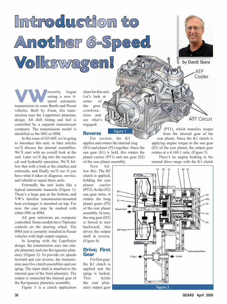
Externally the unit looks like a typical automatic transaxle (Figure 1). There’s a large pan at the bottom, and VW’s familiar transmission-mounted heat exchanger is mounted on top. For now, the case may be marked with either 09G or 09M.
All gear selections are computer controlled. Some models have Tiptronic controls on the steering wheel. The 09M unit is currently installed in Passat vehicles with high output engines.
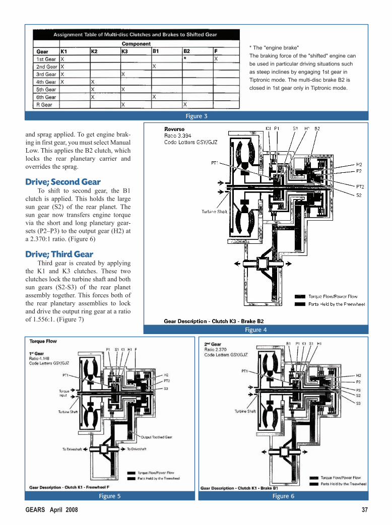
In keeping with the Lepelletier design, the transmission uses one sim-ple planetary and one Ravigneaux plan-etary (Figure 2). To provide six speeds forward and one reverse, the transmis-sion uses five clutch assemblies and one sprag. The input shaft is attached to the internal gear of the front planetary. The output is connected the internal gear of the Ravigneaux planetary assembly.
Figure 3 is a clutch application
chart for this unit. Let’s look at some of the gear combina-tions and see what’s engaged:
Reverse For reverse, the K3
applies and rotates the internal ring (H1) and planet (P1) together. Since the sun gear (S1) is held, this rotates the planet carrier (PT1) and sun gear (S2) of the rear planet assembly.
Now fol-low this: The B2 clutch is applied, holding the rear planet carrier (PT2). As the (S2) sun gear turns, it rotates the long planet gears (P2) of the rear planet assembly. In turn, the ring gear (H2) is forced to turn backward; this drives the output shaft in reverse. (Figure 4)
Drive; First Gear
For first gear, the K1 clutch is applied and the sprag is locked. This holds the rear plan-etary output gear
(PT1), which transfers torque from the internal gear of the
rear planet. Since the K1 clutch is applying engine torque to the sun gear (S3) of the rear planet, the output gear rotates at a 4.148:1 ratio. (Figure 5)
There’s no engine braking in the normal drive range with the K1 clutch
Introduction to Another 6-Speed Volkswagen! by David Skora
Figure 2
Figure 1
GEARS April 2008 37
and sprag applied. To get engine brak-ing in first gear, you must select Manual Low. This applies the B2 clutch, which locks the rear planetary carrier and overrides the sprag.
Drive; Second GearTo shift to second gear, the B1
clutch is applied. This holds the large sun gear (S2) of the rear planet. The sun gear now transfers engine torque via the short and long planetary gear-sets (P2–P3) to the output gear (H2) at a 2.370:1 ratio. (Figure 6)
Drive; Third GearThird gear is created by applying
the K1 and K3 clutches. These two clutches lock the turbine shaft and both sun gears (S2-S3) of the rear planet assembly together. This forces both of the rear planetary assemblies to lock and drive the output ring gear at a ratio of 1.556:1. (Figure 7)
Figure 3
Figure 4
Figure 5 Figure 6
* The "engine brake"
The braking force of the "shifted" engine can
be used in particular driving situations such
as steep inclines by engaging 1st gear in
Tiptronic mode. The multi-disc brake B2 is
closed in 1st gear only in Tiptronic mode.

38 GEARSApril2008
Skipping to SixthSixth speed made by applying the
K2 and B1 clutches. The B1 holds the front sun gear (S2) of the rear planet assembly. The K2 clutch locks the rotating turbine shaft to the planetary carriers (PT1-PT2) of the rear planet. The carrier then overdrives the output gear with a ratio of 0.686:1. (Figure 8)
A Few Details…The transmission control module
(TCM) is located inside left fender panel. The TCM is networked to the CAN data bus. This allows the TCM to select the best gear based on inputs from the ECM, ABS, gear selector, vehicle electrical system control mod-ule, and steering wheel module (if equipped with steering wheel shift con-trols).
With these controls, the TCM can actuate all the solenoids, which applies the correct clutches. When the driver or an onboard module signals a sufficient change in the vehicle’s operation, the TCM will shift to another gear range.
A gear-driven oil pump provides all fluid pressure to operate the hydrau-lic solenoids (Figure 9), applying the clutches and cooling. In failsafe, the
Figure 7 Figure 8
Figure 9
Introduction to Another 6-Speed Volkswagen!

GEARS April 2008 39
transmission will operate in 3rd gear only.
A drain and fluid level plug is pro-vided at the bottom of the transmission case. Above the fluid level plug is an oil level tube similar to the 4-speed 01M units. The manufacturer recommends that the fluid level be checked with the transmission in park, engine idling, and the transmission fluid temperature between 95º–130ºF.
The correct fluid is G052 182. A
complete fill is about 7L. Draining and refilling is about 5L.
At this time, the only part available from the manufacturer is a complete valve body assembly. (See Chart 1)
This preliminary information should help you understand the basic operation of the 09G/09M transmission. To diagnose these systems, you’ll need the most current software for your scan tool, preferably a VAG type, and CAN-
compatible equipment to troubleshoot all the systems and isolate problems from other computers that interact with the TCM. Look for more information as it becomes available.
Shift Solenoids Controls Solenoid Type
1 (N88) NC On for 4th–6th gears On/Off
2 (N89) NC On for TCC and B1 in Low On/Off
3 (N90) NC Regulates K1 Pressure Modulating
4 (N91) NO Regulates TCC Pressure Modulating
5 (N92) NC Regulates K3 Pressure Modulating
6 (N93) NC Regulates Mainline Modulating
9 (N282) NC Regulates K2 Pressure Modulating
10 (N283) NC Regulates B1 Pressure Modulating
Chart 1