6.7.6.3 ric uac assembly nipple seal gasket removal and
TRANSCRIPT

S6220-EN-MMO-010
Figure 6-104. HUD Electrical Cable and Remote Pressure Indicator Console Connections.
(9) Screw the knurled part of the HUD electrical connection into the remote pressure indicatorconsole, turning CW until tight. Do not overtighten.
(10) Slide the plastic cap over the HUD electrical cable and fasten by turning it CW until tight.Do not overtighten.
(11) Attach remote pressure indicator console to harness by stretching rubber strap hole (1,Figure 6-97) around knob on side of remote pressure indicator console. Repeat for otherside.
(12) Install cylinder assembly IAW paragraph 2.3.2.2.(13) Perform leak check IAW paragraph 6.6.2.
6.7.6.3 RIC UAC Assembly Nipple Seal Gasket Removal and Installation.Tools, Parts, and Materials.
• Gasket, Nipple Seal, PN 57264-00• Wrench, socket head key (Allen wrench), 1/8 inch• Wrench, open-end, 1/2 incha. Removal.
(1) Bleed system IAW paragraph 6.6.1.(2) Rotate hand coupling (4, Figure 6-105) CCW and remove RIC UAC assembly from cylinder
valve.
6-70

S6220-EN-MMO-010
Figure 6-105. RIC UAC Assembly Nipple Seal Gasket.
NOTE
Do not remove hand coupling from RIC UAC assembly when replacing nippleseal gasket. Only remove retaining screw and nipple seal gasket.
(3) Hold nipple seal shaft under hand coupling with 1/2 inch open-end wrench while using 1/8inch socket head key wrench to remove retaining screw (1) from center of nipple seal shaft(3) and set aside for installation.
(4) Remove nipple seal gasket (2) and discard.b. Installation.
(1) Inspect new nipple seal gasket for any damage. Replace as required.(2) Install nipple seal gasket (2) onto center of nipple seal shaft (3).(3) Hold nipple seal shaft under hand coupling with 1/2 inch open-end wrench and use 1/8 inch
socket head key wrench to install retaining screw (1) into center of nipple seal shaft.(4) Rotate hand coupling (4) CW to reconnect RIC UAC assembly to cylinder valve.(5) Perform leak check IAW paragraph 6.6.2.
6.7.6.4 RIC UAC Assembly Removal and Installation.Tools, Parts, and Materials.
• Hammer, hand, machinist’s ballpeen, 8 oz.• O-ring, PN 55622-00• Punch, pin 1/8 inch• Ring, backup, PN 18071-02a. Removal.
(1) Bleed system IAW paragraph 6.6.1.
6-71

S6220-EN-MMO-010
(2) Remove cylinder assembly IAW paragraph 2.3.2.2.(3) Lay backframe and harness assembly on clean work surface with cylinder band clamp facing
down.(4) Using punch pin and hammer, tap out two roll pins (2, Figure 6-106) securing RIC UAC
assembly (1) to pressure reducer (3).
Figure 6-106. RIC UAC Assembly Removal.
(5) Pull RIC UAC assembly from pressure reducer.b. Installation.
(1) Inspect O-ring (1, Figure 6-107) and backup ring (2) on RIC UAC assembly for nicks, cuts,wear and tear, or foreign debris. If necessary, remove and replace IAW paragraph 4.7.5.
Figure 6-107. RIC UAC Assembly O-ring, and Backup Ring.
(2) Inspect roll pins for cracks, bends, or mushroomed ends. Replace as required.
CAUTION
To prevent equipment damage, ensure RIC UAC assembly inlet port is free offoreign matter before installing RIC UAC assembly.
(3) Insert RIC UAC assembly (1, Figure 6-106) into pressure reducer. Ensure RIC UACassembly groove (3, Figure 6-107) aligns with pinholes and that pinholes are unobstructed.
6-72

S6220-EN-MMO-010
CAUTION
Ensure RIC UAC assembly groove aligns with pin holes to prevent damage toequipment.
(4) While holding RIC UAC assembly firmly in place, insert roll pins (2, Figure 6-106) andlightly tap in place with hammer until roll pins are flush with pressure reducer (3).
(5) Replace cylinder assembly IAW paragraph 2.3.2.2.(6) Perform leak check IAW paragraph 6.6.2.
6.7.6.5 Pressure Reducer Removal and Installation.Tools, Parts, and Materials.
• Wrench, open-end, 5/8 inch• Wrench, socket head key (Allen Wrench), 7/64 inch• Wrench, socket head key (Allen Wrench), 3/32 inch• Wrench, socket head key (Allen Wrench), 5/32 incha. Removal.
(1) Bleed system IAW paragraph 6.6.1.(2) Remove cylinder assembly IAW paragraph 2.3.2.2.(3) Remove RIC UAC assembly IAW paragraph 6.7.6.4.(4) Remove anti-rotational device (1, Figure 6-108) on low-pressure hose (2) using 7/64 inch
socket head key wrench on two socket head screws (3), turning fully CCW. Set parts asidefor installation.
Figure 6-108. Anti-Rotational Device on Low-Pressure Hose.
(5) Using 5/8 inch open-end wrench, remove low-pressure hose (2) by rotating low-pressurehose coupling fully CCW. Ensure cleanliness is maintained IAW paragraph 4.7.1.
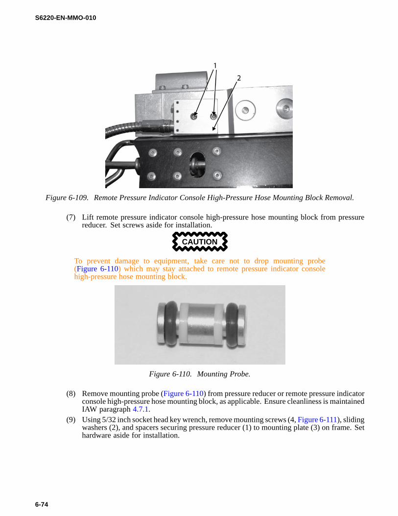
(6) Using 3/32 inch socket head key wrench, loosen two screws (1, Figure 6-109) from remotepressure indicator console high-pressure hose mounting block (2).
6-73
S6220-EN-MMO-010
Figure 6-109. Remote Pressure Indicator Console High-Pressure Hose Mounting Block Removal.
(7) Lift remote pressure indicator console high-pressure hose mounting block from pressurereducer. Set screws aside for installation.
CAUTION
To prevent damage to equipment, take care not to drop mounting probe(Figure 6-110) which may stay attached to remote pressure indicator consolehigh-pressure hose mounting block.
Figure 6-110. Mounting Probe.
(8) Remove mounting probe (Figure 6-110) from pressure reducer or remote pressure indicatorconsole high-pressure hose mounting block, as applicable. Ensure cleanliness is maintainedIAW paragraph 4.7.1.
(9) Using 5/32 inch socket head key wrench, remove mounting screws (4, Figure 6-111), slidingwashers (2), and spacers securing pressure reducer (1) to mounting plate (3) on frame. Sethardware aside for installation.
6-74

S6220-EN-MMO-010
Figure 6-111. Pressure Reducer Removal.
b. Installation.(1) Inspect pressure reducer for any visible sign of damage. Replace as required.(2) Install pressure reducer (1) onto mounting plate (3) on frame with 5/32 inch socket head
key wrench, using mounting screws (4), sliding washers (2), and spacers.(3) Fully seat mounting probe into pressure reducer.(4) Carefully place remote pressure indicator console high-pressure hose mounting block over
mounting probe and onto pressure reducer.(5) Using 3/32 inch socket head key wrench, install two screws (1, Figure 6-109) into remote
pressure indicator console high-pressure hose mounting block (2), turning CW until tight.Do not overtighten.
(6) Using 5/8 inch open-end wrench, install low-pressure hose by rotating low-pressure hosecoupling fully CW until tight. Do not overtighten.
(7) Install anti-rotational device on low-pressure hose using 7/64 inch socket head key wrenchon two socket head screws, turning fully CW until tight. Do not overtighten.
NOTEPerform leak check after all components have been installed.
(8) Install RIC UAC assembly IAW paragraph 6.7.5.4.(9) Replace cylinder assembly IAW paragraph 2.3.2.2.(10) Perform leak check IAW paragraph 6.6.2.
6.7.6.6 Remote Pressure Indicator Console High-Pressure Hose Removal and Installation.Tools, Parts, and Materials.
• Hammer, hand, machinists’ ball peen, 8 oz.• Punch, pin, 5/64 inch• Wrench, socket head key (Allen wrench), 3/32 incha. Removal.
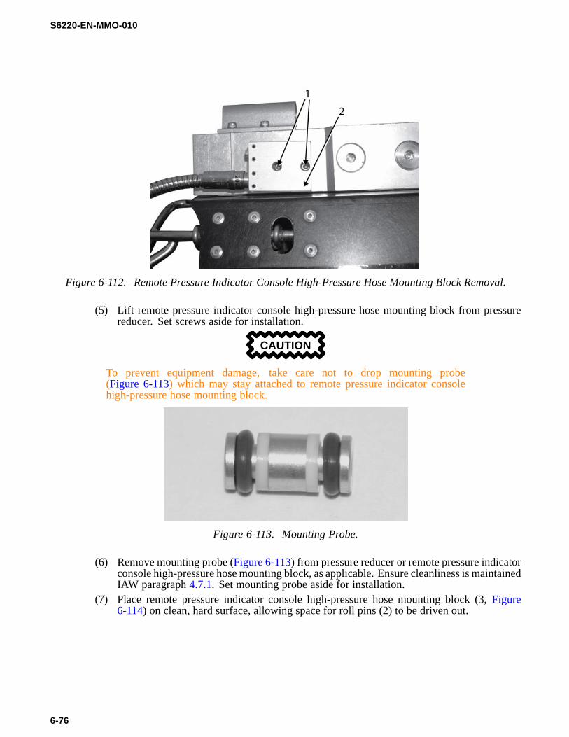
(1) Bleed system IAW paragraph 6.6.1.(2) Remove cylinder assembly IAW paragraph 2.3.2.2.(3) Remove remote pressure indicator console IAW paragraph 6.7.6.2.(4) Using 3/32 inch socket head key wrench, fully loosen two screws (1, Figure 6-112) from
remote pressure indicator console high-pressure hose mounting block (2).
6-75
S6220-EN-MMO-010
Figure 6-112. Remote Pressure Indicator Console High-Pressure Hose Mounting Block Removal.
(5) Lift remote pressure indicator console high-pressure hose mounting block from pressurereducer. Set screws aside for installation.
CAUTION
To prevent equipment damage, take care not to drop mounting probe(Figure 6-113) which may stay attached to remote pressure indicator consolehigh-pressure hose mounting block.
Figure 6-113. Mounting Probe.
(6) Remove mounting probe (Figure 6-113) from pressure reducer or remote pressure indicatorconsole high-pressure hose mounting block, as applicable. Ensure cleanliness is maintainedIAW paragraph 4.7.1. Set mounting probe aside for installation.
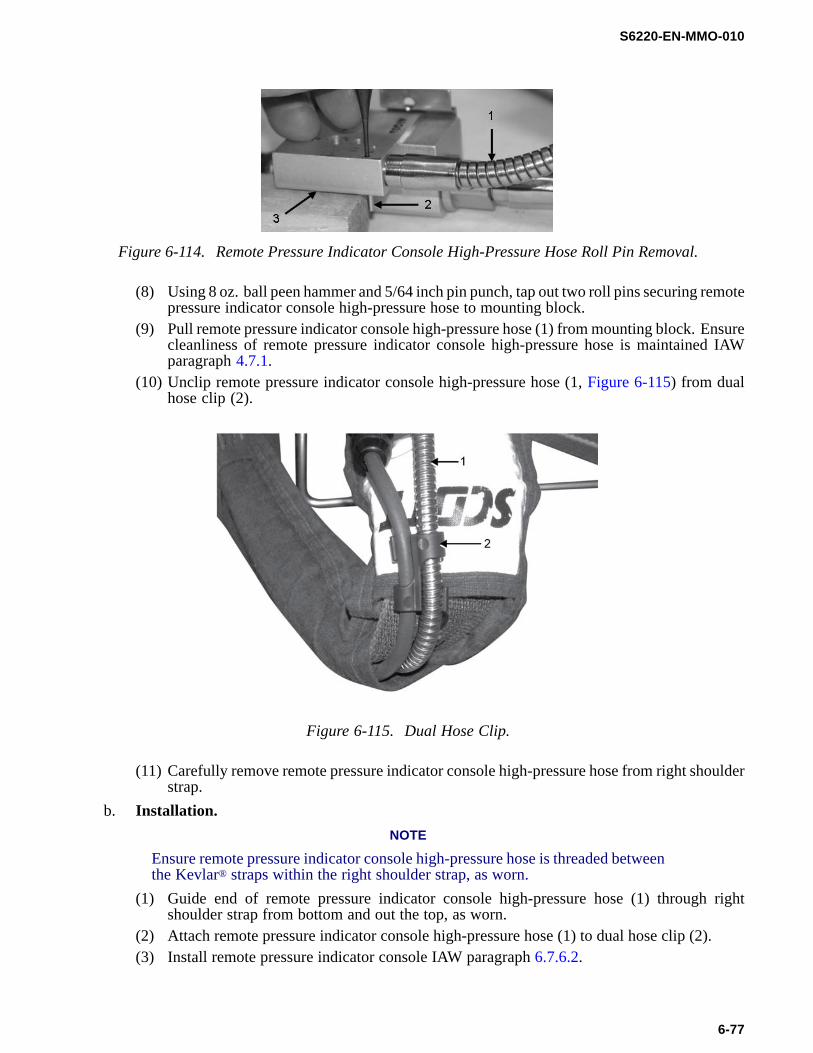
(7) Place remote pressure indicator console high-pressure hose mounting block (3, Figure6-114) on clean, hard surface, allowing space for roll pins (2) to be driven out.
6-76
S6220-EN-MMO-010
Figure 6-114. Remote Pressure Indicator Console High-Pressure Hose Roll Pin Removal.
(8) Using 8 oz. ball peen hammer and 5/64 inch pin punch, tap out two roll pins securing remotepressure indicator console high-pressure hose to mounting block.
(9) Pull remote pressure indicator console high-pressure hose (1) from mounting block. Ensurecleanliness of remote pressure indicator console high-pressure hose is maintained IAWparagraph 4.7.1.
(10) Unclip remote pressure indicator console high-pressure hose (1, Figure 6-115) from dualhose clip (2).
Figure 6-115. Dual Hose Clip.
(11) Carefully remove remote pressure indicator console high-pressure hose from right shoulderstrap.
b. Installation.NOTE
Ensure remote pressure indicator console high-pressure hose is threaded betweenthe Kevlar® straps within the right shoulder strap, as worn.
(1) Guide end of remote pressure indicator console high-pressure hose (1) through rightshoulder strap from bottom and out the top, as worn.
(2) Attach remote pressure indicator console high-pressure hose (1) to dual hose clip (2).(3) Install remote pressure indicator console IAW paragraph 6.7.6.2.
6-77

S6220-EN-MMO-010
NOTE
Backup ring is a split ring.(4) Inspect o-ring (1, Figure 6-116) and backup ring (2) on remote pressure indicator console
high-pressure hose for nicks, cuts, wear and tear, or foreign debris. As necessary, removeand replace IAW paragraph 4.7.5.
Figure 6-116. Remote Pressure Indicator Console High-Pressure Hose O-Ring and Backup Ring.
CAUTION
To prevent equipment damage, ensure remote pressure indicator consolehigh-pressure hose mounting block outlet port is free of foreign matter beforeinserting remote pressure indicator console high-pressure hose .
(5) Insert remote pressure indicator console high-pressure hose fully into remote pressureindicator console high-pressure hose mounting block outlet port. Ensure hose groove (3)is aligned with roll pin holes and that roll pin holes are unobstructed.
(6) Inspect roll pin holes for cracks, bends, or mushroomed ends. Replace as required.(7) Tap roll pins into roll pin holes using 5/64 inch pin punch and 8 oz. ball peen hammer.(8) Fully seat mounting probe into pressure reducer.(9) Carefully place remote pressure indicator console high-pressure hose mounting block over
mounting probe and onto pressure reducer.(10) Using 3/32 inch socket head key wrench, install two screws (1, Figure 6-109) into remote
pressure indicator console high-pressure hose mounting block (2), turning CW until tight.Do not overtighten.
(11) Replace cylinder assembly IAW paragraph 2.3.2.2.(12) Perform leak check IAW paragraph 6.6.2.
6-78

S6220-EN-MMO-010
6.7.7 Backframe and Harness Assembly Corrective Maintenance.
6.7.7.1 Hip Pad Assembly Removal and Installation.
a. Removal.(1) Bleed system IAW paragraph 6.6.1.(2) Remove cylinder assembly IAW paragraph 2.3.2.2.(3) Remove side strap (4, Figure 6-117) from shoulder strap spring-action buckle (3). Repeat
for the other side strap.
Figure 6-117. Remove Hip Pad Assembly.
(4) Remove waist adjustment strap (1) from waist strap spring-action buckle (2). Repeat forother waist adjustment strap.
(5) Unsnap hip pad assembly from backframe.
CAUTION
Do not use tools to remove hip pad assembly; tools may damage equipment.(6) Pull hip pad assemblies from waist-strap spring-action buckles and side straps.
b. Installation.(1) Inspect hip pad assembly for any visible signs of damage. Replace as required.(2) Position hip pad assembly with snap receptacles facing up as shown in Figure 6-118.
6-79

S6220-EN-MMO-010
Figure 6-118. Hip Pad Assembly Installation.
(3) Feed waist strap spring-action buckles (2, Figure 6-117) and side straps (4) through hipassembly (5); position side straps.
(4) Snap hip pad assembly to backframe.(5) Feed side strap through shoulder strap spring action buckle (3). Folded seam will face teeth
of buckle. Repeat for other side strap.(6) Repeat step (5) for waist adjustment straps (1) and waist strap spring-action buckles.(7) Replace cylinder assembly IAW paragraph 2.3.2.2.(8) Perform leak check IAW paragraph 6.6.2.
6.7.7.2 Shoulder Pad Assembly Removal and Installation.
a. Removal.(1) Bleed system IAW paragraph 6.6.1.
NOTE
Remove only those components necessary to replace affected shoulder pad.(2) Remove bell alarm IAW paragraph 6.7.4.3 (Configurations 2 and 3).(3) Remove mask-mounted regulator IAW paragraph 6.7.3.2.(4) Remove remote pressure indicator IAW either paragraph 6.7.4.2 for Configurations 1-3,
paragraph 6.7.5.1 for Configuration 4, or paragraph 6.7.6.2 for Configuration 5.(5) Unsnap shoulder strap from shoulder pad.(6) Remove side strap (4, Figure 6-119) from shoulder strap spring-action buckle (3).
6-80

S6220-EN-MMO-010
Figure 6-119. Remove Shoulder Pad Assembly.
(7) Remove shoulder pad assembly (5).b. Installation.
(1) Inspect shoulder pad assembly for any visible sign of damage. Replace as required.(2) Position shoulder pad assembly (5) with label facing up.(3) Feed shoulder strap spring-action buckle (3) through shoulder pad assembly.(4) Snap shoulder strap to shoulder pad assembly.(5) Feed side strap through shoulder strap spring-action buckle. Folded seam will face teeth of
buckle.NOTE
Perform leak check after all components have been reinstalled.(6) Install remote pressure indicator IAW either paragraph 6.7.4.2 for Configurations 1-3,
paragraph 6.7.5.1 for Configuration 4, or paragraph 6.7.6.2 for Configuration 5.(7) Install mask-mounted regulator IAW paragraph 6.7.3.2.(8) Install bell alarm IAW paragraph 6.7.4.3 (Configurations 2 and 3).(9) Perform leak check IAW paragraph 6.6.2.
6.7.7.3 Backframe and Harness Assembly Removal and Installation.Tools, Parts, and Materials.
• Wrench, socket head key (Allen wrench), 5/32 incha. Removal.
(1) Bleed system IAW paragraph 6.6.1.(2) Remove cylinder assembly IAW 2.3.2.2.(3) Remove mask-mounted regulator IAW 6.7.3.2.(4) Remove bell alarm IAW paragraph 6.7.4.3 (Configurations 2 and 3).(5) Remove remote pressure indicator IAW either paragraph 6.7.4.2 for Configurations 1-3 or
paragraph 6.7.5.1 for Configuration 4.(6) Using 5/32 inch socket head key wrench, remove mounting screws and sliding washers (1,
Figure 6-120) from mounting plate (4). Set aside for installation.
6-81

S6220-EN-MMO-010
Figure 6-120. Remove Pressure Reducer.
(7) Remove pressure reducer (3) from mounting plate.b. Installation.
(1) Inspect backframe and harness assembly for any visible sign of damage. Replace asrequired.
(2) Inspect pressure reducer for any visible sign of damage. Replace as required.(3) Align screw holes in side of pressure reducer (3) with slots (2) in mounting plate.(4) Using 5/32 inch socket head key wrench, install mounting screws and sliding washers (1).
NOTE
Perform leak check after all components have been reinstalled.(5) Install remote pressure indicator IAW either paragraph 6.7.4.2 for Configurations 1-3,
paragraph 6.7.5.1 for Configuration 4, or paragraph 6.7.6.2 for Configuration 5.(6) Install bell alarm IAW paragraph 6.7.4.3 (Configurations 2 and 3).(7) Install mask-mounted regulator IAW paragraph 6.7.3.2.(8) Replace cylinder assembly IAW paragraph 2.3.2.2.(9) Perform leak check IAW paragraph 6.6.2.
6-82