ΧΦ65/75/85 series
TRANSCRIPT
STRUCTURE
© 200423 DW23241603
0
1
2
3
4
5
6
ΧΦ65/75/85 series
6
Structure
TECHNICAL DATA
DIAGNOSTICS
BRAKE DIAGRAMS FOR THE FULLY PNEUMATIC BRAKE SYSTEM
EBS BRAKE SYSTEM BRAKE DIAGRAMS
OPERATION OF BRAKE COMPONENTS
BRAKE SYSTEM AND COMPONENTS
BRAKING PERFORMANCE AND BRAKE EQUALISATION
https://www.truck-manuals.net/

https://www.truck-manuals.net/
© 200423 1
Contents
TECHNICAL DATA
ΧΦ65/75/85 series
6
0
0 Technical data
CONTENTS
Page Date
1. BRAKE SYSTEM AND COMPONENTS. . . . . . . . . . . . . . . . . . . . . . . . . . . . . . . 1-1 . . . . . 200423
1.1 General . . . . . . . . . . . . . . . . . . . . . . . . . . . . . . . . . . . . . . . . . . . . . . . . . . 1-1 . . . . . 200423
1.2 Tightening torques. . . . . . . . . . . . . . . . . . . . . . . . . . . . . . . . . . . . . . . . . . . 1-16 . . . . 200423
1.3 Lubricants . . . . . . . . . . . . . . . . . . . . . . . . . . . . . . . . . . . . . . . . . . . . . . . . 1-19 . . . . 200423
2. BRAKING PERFORMANCE AND BRAKE EQUALISATION . . . . . . . . . . . . . . 2-1 . . . . . 200423
2.1 General . . . . . . . . . . . . . . . . . . . . . . . . . . . . . . . . . . . . . . . . . . . . . . . . . . 2-1 . . . . . 200423
https://www.truck-manuals.net/

TECHNICAL DATA
2 © 200423
Contents
0
ΧΦ65/75/85 series
6
https://www.truck-manuals.net/
© 200423 1-1
Brake system and components
TECHNICAL DATA
ΧΦ65/75/85 series
6
01. BRAKE SYSTEM AND COMPONENTS
1.1 GENERAL
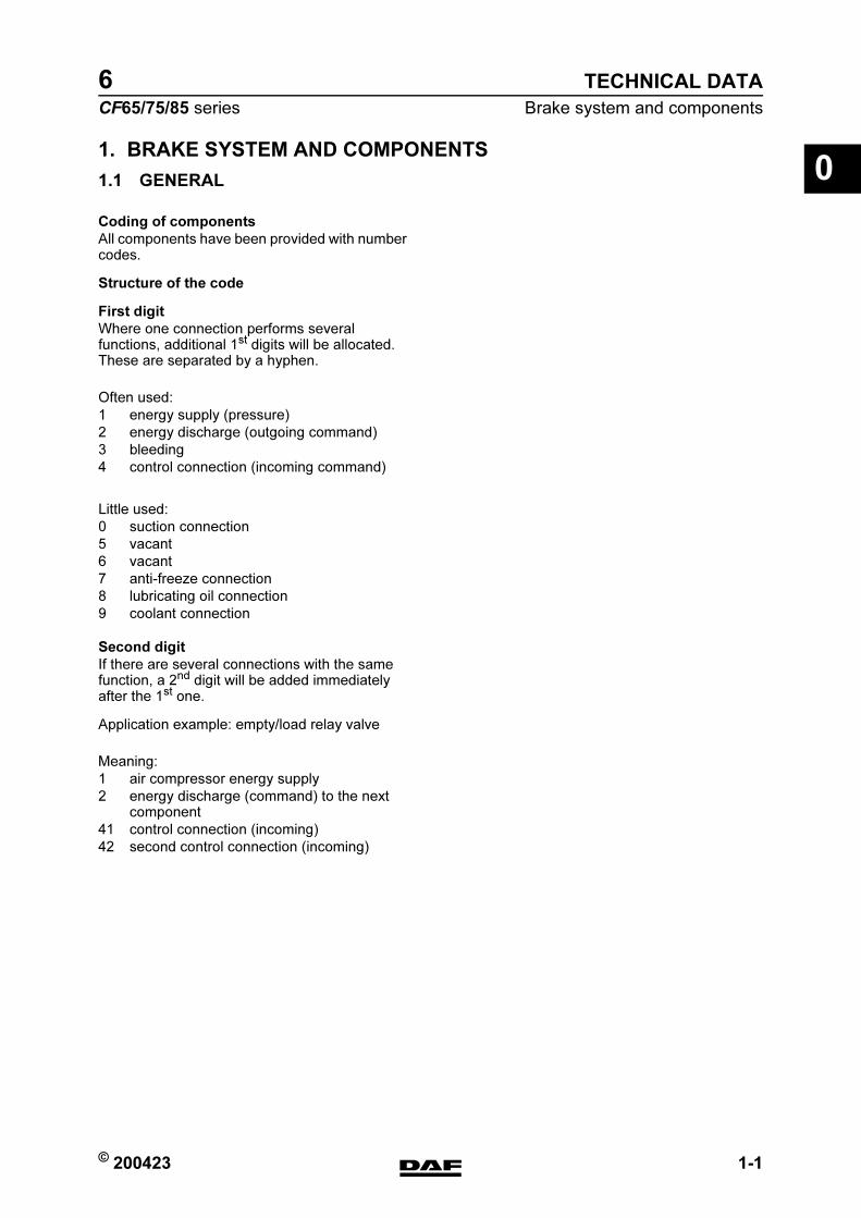
Coding of components
All components have been provided with number codes.
Structure of the code
First digit
Where one connection performs several functions, additional 1st digits will be allocated. These are separated by a hyphen.
Second digit
If there are several connections with the same function, a 2nd digit will be added immediately after the 1st one.
Application example: empty/load relay valve
Often used:
1 energy supply (pressure)
2 energy discharge (outgoing command)
3 bleeding
4 control connection (incoming command)
Little used:
0 suction connection
5 vacant
6 vacant
7 anti-freeze connection
8 lubricating oil connection
9 coolant connection
Meaning:
1 air compressor energy supply
2 energy discharge (command) to the next component
41 control connection (incoming)
42 second control connection (incoming)
https://www.truck-manuals.net/

TECHNICAL DATA
1-2 © 200423
Brake system and components
0
ΧΦ65/75/85 series
6
Compressor
CF65 series
Type
CF75/85 series
Type
Rejection sizes Wabco 911 504 ... compressor
Make: Knorr SWC 9057
Version: 1 cylinder, water cooled, 255 cc
Make: Wabco 911 504 ...
Version: 2 cylinder, water cooled
Cylinder bore at the turning point of the first piston ring 75.022 mm
Height of piston ring groove:
first groove: 2.035 mm
second groove: 2.035 mm
third groove: 4.047 mm
Gudgeon pin hole diameter: 15.018 mm
Gudgeon pin diameter: 14.992 mm
Piston diameter, measured along the length of the piston pen on the underside of the piston skirt. 74.962 mm
Gudgeon pin bearing in connecting rod: 15.047 mm
Crankshaft bearing diameter, non-drive side: 35.070 mm
Crankshaft main bearing, non-drive side: 34.963 mm
Crankshaft diameter at the connecting rod: 32.963 mm
Always replace rolling bearing on drive side
https://www.truck-manuals.net/
© 200423 1-3
Brake system and components
TECHNICAL DATA
ΧΦ65/75/85 series
6
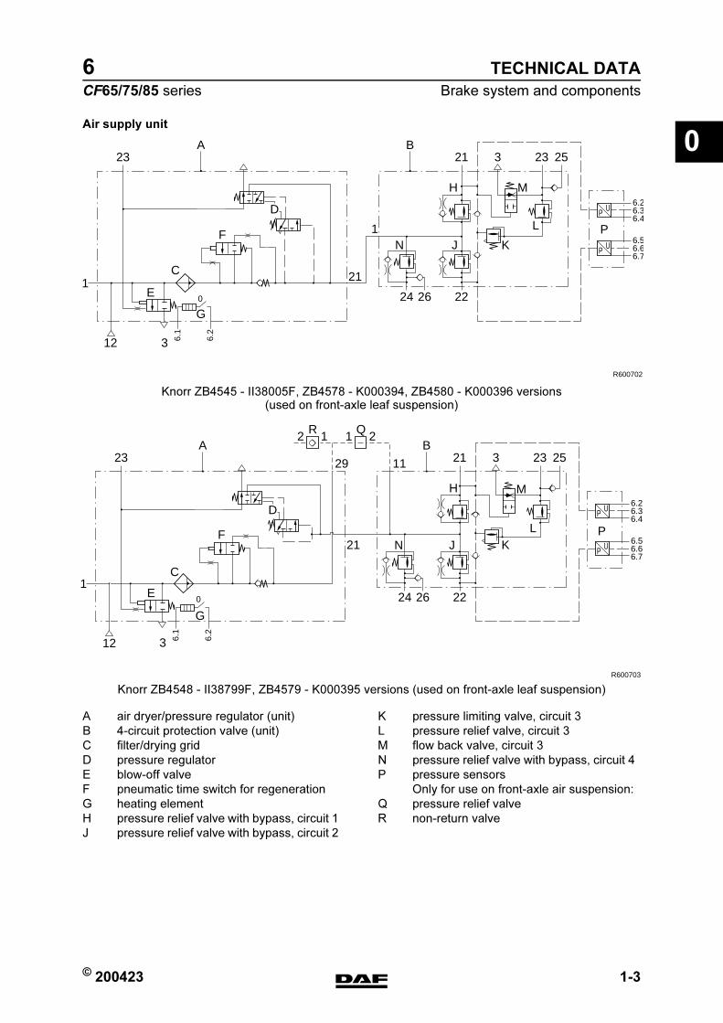
0Air supply unit
Knorr ZB4545 - II38005F, ZB4578 - K000394, ZB4580 - K000396 versions (used on front-axle leaf suspension)
24
21
1F
D
N J K
L
MH
P
3
A
E
C
G
1
12
26 22
2123 3 23 25
P U6.26.36.4
6.1
6.2
P U6.56.66.7
B
R600702
0
Knorr ZB4548 - II38799F, ZB4579 - K000395 versions (used on front-axle leaf suspension)
24
21
2 1R
3
126 22
2129 1123 3 23 25
P U6.26.36.4
6.1
6.2
P U6.56.66.7
R600703
0
1 2Q
F
M
P
E
C
G
A B
D
N J
H
K L
12
A air dryer/pressure regulator (unit) K pressure limiting valve, circuit 3
B 4-circuit protection valve (unit) L pressure relief valve, circuit 3
C filter/drying grid M flow back valve, circuit 3
D pressure regulator N pressure relief valve with bypass, circuit 4
E blow-off valve P pressure sensors
F pneumatic time switch for regeneration Only for use on front-axle air suspension:
G heating element Q pressure relief valve
H pressure relief valve with bypass, circuit 1 R non-return valve
J pressure relief valve with bypass, circuit 2
https://www.truck-manuals.net/
TECHNICAL DATA
1-4 © 200423
Brake system and components
0
ΧΦ65/75/85 series
6
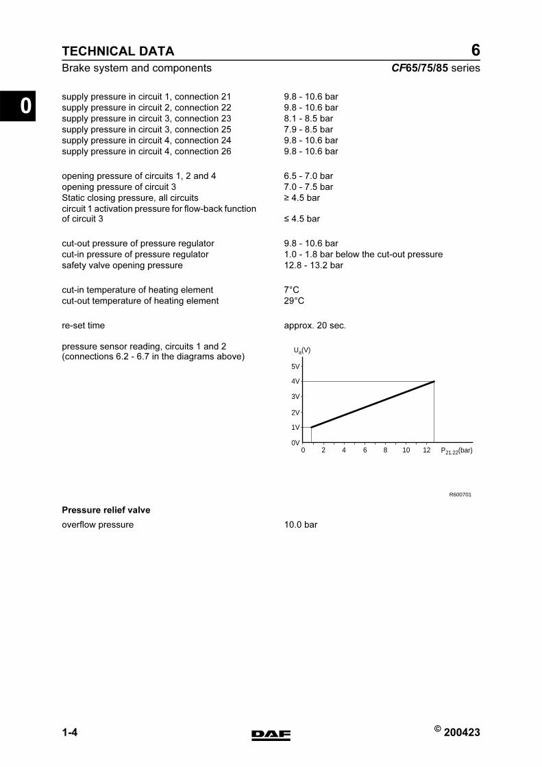
pressure sensor reading, circuits 1 and 2(connections 6.2 - 6.7 in the diagrams above)
Pressure relief valve
supply pressure in circuit 1, connection 21 9.8 - 10.6 bar
supply pressure in circuit 2, connection 22 9.8 - 10.6 bar
supply pressure in circuit 3, connection 23 8.1 - 8.5 bar
supply pressure in circuit 3, connection 25 7.9 - 8.5 bar
supply pressure in circuit 4, connection 24 9.8 - 10.6 bar
supply pressure in circuit 4, connection 26 9.8 - 10.6 bar
opening pressure of circuits 1, 2 and 4 6.5 - 7.0 bar
opening pressure of circuit 3 7.0 - 7.5 bar
Static closing pressure, all circuits 4.5 bar
circuit 1 activation pressure for flow-back function of circuit 3 4.5 bar
cut-out pressure of pressure regulator 9.8 - 10.6 bar
cut-in pressure of pressure regulator 1.0 - 1.8 bar below the cut-out pressure
safety valve opening pressure 12.8 - 13.2 bar
cut-in temperature of heating element 7C
cut-out temperature of heating element 29C
re-set time approx. 20 sec.
1V
0V
2V
3V
4V
5V
120 2 4 6 8 10 P21.22(bar)
Ua(V)
R600701
overflow pressure 10.0 bar
https://www.truck-manuals.net/
© 200423 1-5
Brake system and components
TECHNICAL DATA
ΧΦ65/75/85 series
6
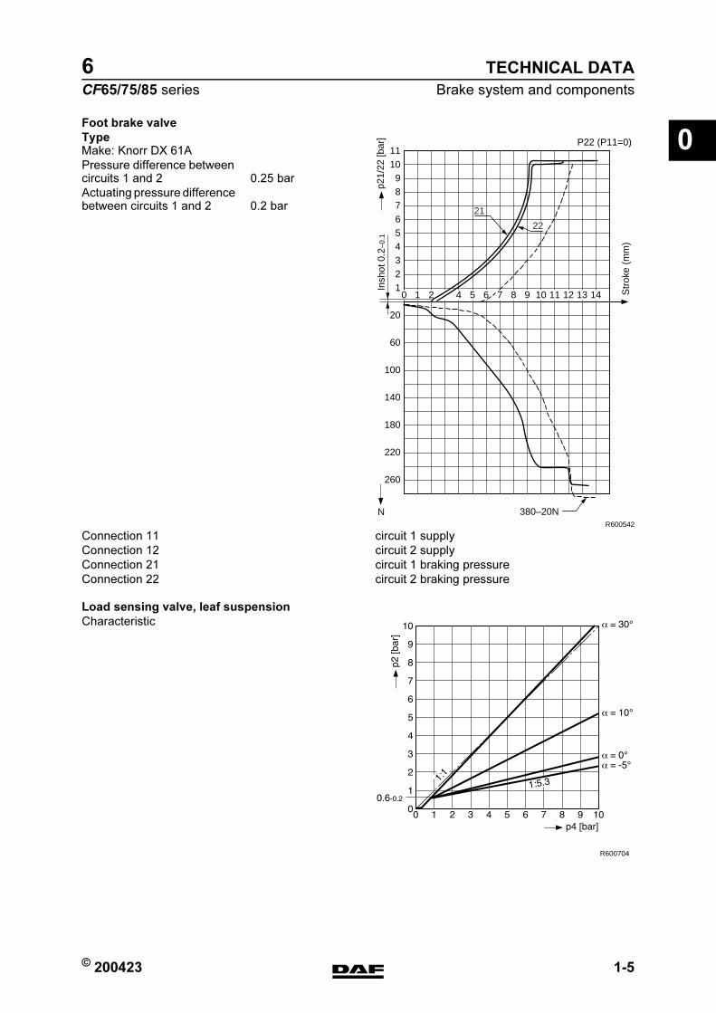
0Foot brake valve
Type
Load sensing valve, leaf suspension
Characteristic
R600542
Insh
ot 0
.2–0
.1
260
220
180
140
100
60
20
123456789
1011
380–20N
p21/
22 [b
ar]
3 4 5 6 7 8 9 10 11 12 13 14
N
Str
oke
(mm
)
21
22
1 20
P22 (P11=0)Make: Knorr DX 61A
Pressure difference between circuits 1 and 2 0.25 bar
Actuating pressure difference between circuits 1 and 2 0.2 bar
Connection 11 circuit 1 supply
Connection 12 circuit 2 supply
Connection 21 circuit 1 braking pressure
Connection 22 circuit 2 braking pressure
R600704
https://www.truck-manuals.net/
TECHNICAL DATA
1-6 © 200423
Brake system and components
0
ΧΦ65/75/85 series
6
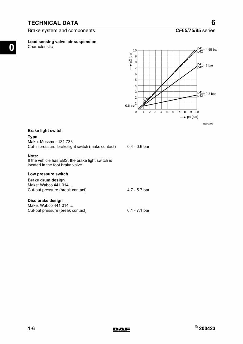
Load sensing valve, air suspension
Characteristic
Brake light switch
Type
Note:If the vehicle has EBS, the brake light switch is located in the foot brake valve.
Low pressure switch
Brake drum design
Disc brake design
10
0.6–0.21
2
3
4
5
6
7
8
9
10
2 3 4 5 6 7 8 9 10
R600705
p41p42= 4.65 bar
p41p42= 3 bar
p41p42= 0.3 bar
p4 [bar]
p2 [b
ar]
1:1
Make: Messmer 131 733
Cut-in pressure, brake light switch (make contact) 0.4 - 0.6 bar
Make: Wabco 441 014 ...
Cut-out pressure (break contact) 4.7 - 5.7 bar
Make: Wabco 441 014 ...
Cut-out pressure (break contact) 6.1 - 7.1 bar
https://www.truck-manuals.net/
© 200423 1-7
Brake system and components
TECHNICAL DATA
ΧΦ65/75/85 series
6
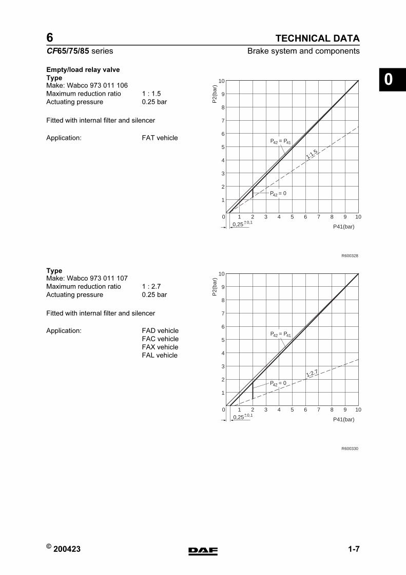
0Empty/load relay valve
Type
Fitted with internal filter and silencer
Type
Fitted with internal filter and silencer
0
1
2
3
4
5
6
7
8
9
10
10,25 P41(bar)
P2(
bar)
R600328
2 3 4 5 6 7 8 9 100,1+
P42 = P41
P42 = 0
1:1.5
Make: Wabco 973 011 106
Maximum reduction ratio 1 : 1.5
Actuating pressure 0.25 bar
Application: FAT vehicle
0
1
2
3
4
5
6
7
8
9
10
10,25 P41(bar)
P2(
bar)
R600330
2 3 4 5 6 7 8 9 100,1+
P42 = P41
P42 = 01:2.7
Make: Wabco 973 011 107
Maximum reduction ratio 1 : 2.7
Actuating pressure 0.25 bar
Application: FAD vehicle
FAC vehicle
FAX vehicle
FAL vehicle
https://www.truck-manuals.net/
TECHNICAL DATA
1-8 © 200423
Brake system and components
0
ΧΦ65/75/85 series
6
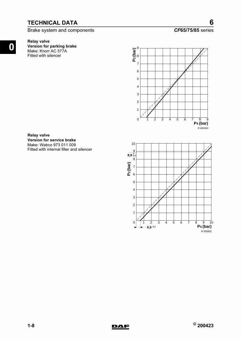
Relay valve
Version for parking brake
Make: Knorr AC 577AFitted with silencer
Relay valve
Version for service brake
Make: Wabco 973 011 009Fitted with internal filter and silencer
10 2 3 4 5 6 7 8 9
1
2
3
4
5
6
7
8
9
P2
(bar
)
P4 (bar)R 600363
10 2 3 4 5 6 7 8 9 10
1
2
3
4
5
6
7
8
98,9
10
P2
(bar
)
P4 (bar)R 600602
0-0,2
0,5–0,1
https://www.truck-manuals.net/
© 200423 1-9
Brake system and components
TECHNICAL DATA
ΧΦ65/75/85 series
6
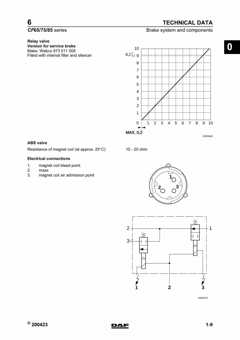
0Relay valve
Version for service brake
Make: Wabco 973 011 008Fitted with internal filter and silencer
ABS valve
Electrical connections
R600640
0
1
2
3
4
5
6
7
8
9
10
MAX. 0,2
9,2 0-0,2
1 2 3 4 5 6 7 8 9 10
Resistance of magnet coil (at approx. 25C) 10 - 20 ohm
1
2 3
2 1
1 2 3
3
R600370
1. magnet coil bleed point
2. mass
3. magnet coil air admission point
https://www.truck-manuals.net/
TECHNICAL DATA
1-10 © 200423
Brake system and components
0
ΧΦ65/75/85 series
6
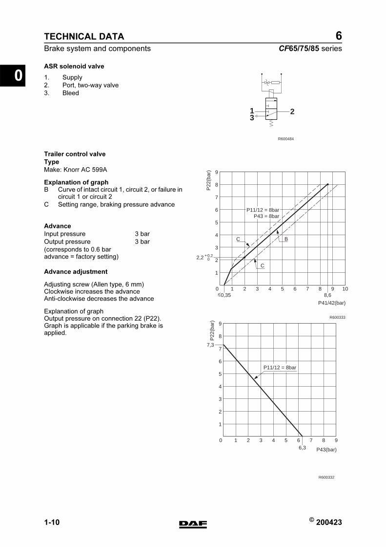
ASR solenoid valve
Trailer control valve
Type
Make: Knorr AC 599A
Explanation of graph
Advance adjustment
Adjusting screw (Allen type, 6 mm)Clockwise increases the advanceAnti-clockwise decreases the advance
Explanation of graphOutput pressure on connection 22 (P22).Graph is applicable if the parking brake is applied.
13
2
R600484
1. Supply
2. Port, two-way valve
3. Bleed
0
1
2
3
4
5
6
7
8
9
1
P41/42(bar)
P22
(bar
)
R600333
2 3 4 5 68,6
7 8 9 10
BC
<0,35
C
2,2 0,20
+
P11/12 = 8barP43 = 8bar
0
1
2
3
4
5
6
7
8
9
1
P43(bar)
P22
(bar
)
R600332
2 3 4 5 66,3
7 8 9
P11/12 = 8bar
7,3
B Curve of intact circuit 1, circuit 2, or failure in circuit 1 or circuit 2
C Setting range, braking pressure advance
Advance
Input pressure 3 bar
Output pressure 3 bar
(corresponds to 0.6 bar advance = factory setting)
https://www.truck-manuals.net/
© 200423 1-11
Brake system and components
TECHNICAL DATA
ΧΦ65/75/85 series
6
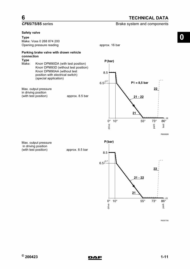
0Safety valve
Type
Parking brake valve with drawn vehicle
connection
Type
Make: Voss 0 268 874 200
Opening pressure reading approx. 16 bar
Make: Knorr DPM90DA (with test position)
Knorr DPM93D (without test position)
Knorr DPM90AA (without test position with electrical switch) (special application)
Max. output pressure in driving position (with test position) approx. 8.5 bar
R600706
Max. output pressure in driving position (with test position) approx. 8.5 bar
https://www.truck-manuals.net/

TECHNICAL DATA
1-12 © 200423
Brake system and components
0
ΧΦ65/75/85 series
6
Parking brake without drawn vehicle
connection
Type
Brake lining
Drum brakes
The bearing pattern of the brake lining can be improved by grinding down the brake lining to a diameter which is max. 1 mm smaller than the drum diameter.The space between brake shoe and lining must not be more than 0.1 mm.
Minimum brake lining thicknessheight of wear indicator or 1 mm above rivet head
Make: Knorr DPM92D
Max. output pressure in driving position approx. 8.5 bar
TYPE NOTES
DAF 2100 Installed on LHD vehicles
DAF 3100 Installed on RHD vehicles
Beral 1561 09N044 leading rear axle (used on FTP vehicle)
M6002
https://www.truck-manuals.net/
© 200423 1-13
Brake system and components
TECHNICAL DATA
ΧΦ65/75/85 series
6
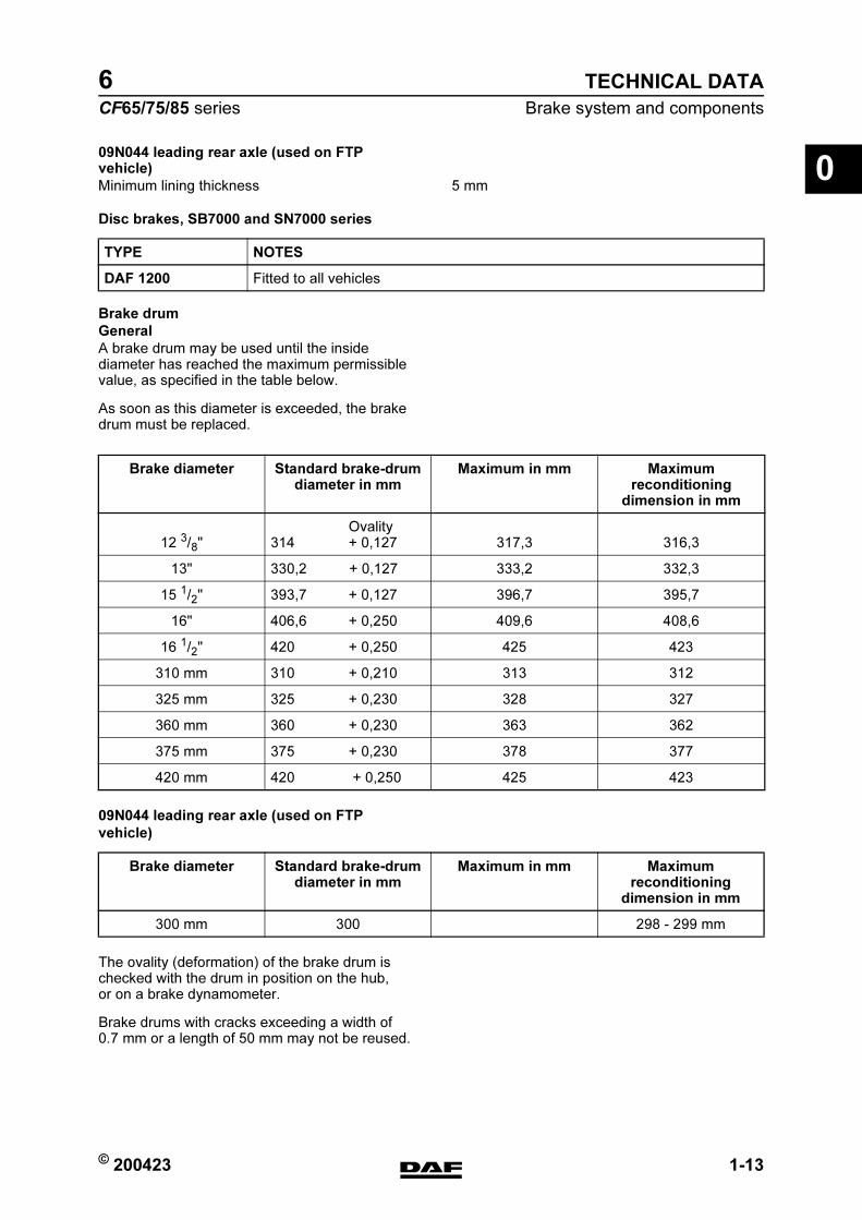
009N044 leading rear axle (used on FTP vehicle)
Disc brakes, SB7000 and SN7000 series
Brake drum
General
A brake drum may be used until the inside diameter has reached the maximum permissible value, as specified in the table below.
As soon as this diameter is exceeded, the brake drum must be replaced.
09N044 leading rear axle (used on FTP
vehicle)
The ovality (deformation) of the brake drum is checked with the drum in position on the hub, or on a brake dynamometer.
Brake drums with cracks exceeding a width of 0.7 mm or a length of 50 mm may not be reused.
Minimum lining thickness 5 mm
TYPE NOTES
DAF 1200 Fitted to all vehicles
Brake diameter Standard brake-drum diameter in mm
Maximum in mm Maximum reconditioning
dimension in mm
12 3/8" Ovality314 + 0,127 317,3 316,3
13" 330,2 + 0,127 333,2 332,3
15 1/2" 393,7 + 0,127 396,7 395,7
16" 406,6 + 0,250 409,6 408,6
16 1/2" 420 + 0,250 425 423
310 mm 310 + 0,210 313 312
325 mm 325 + 0,230 328 327
360 mm 360 + 0,230 363 362
375 mm 375 + 0,230 378 377
420 mm 420 + 0,250 425 423
Brake diameter Standard brake-drum diameter in mm
Maximum in mm Maximum reconditioning
dimension in mm
300 mm 300 298 - 299 mm
https://www.truck-manuals.net/
TECHNICAL DATA
1-14 © 200423
Brake system and components
0
ΧΦ65/75/85 series
6
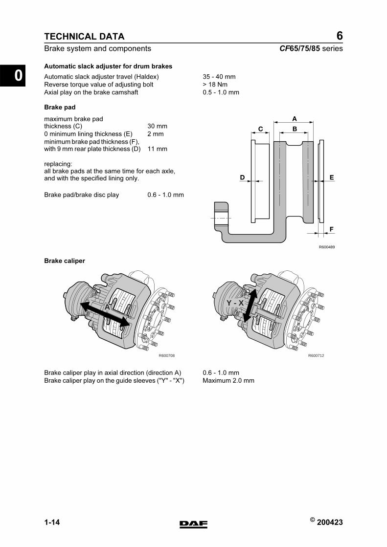
Automatic slack adjuster for drum brakes
Brake pad
replacing:all brake pads at the same time for each axle, and with the specified lining only.
Brake caliper
Automatic slack adjuster travel (Haldex) 35 - 40 mm
Reverse torque value of adjusting bolt > 18 Nm
Axial play on the brake camshaft 0.5 - 1.0 mm
R600489
A
B
F
ED
C
maximum brake pad thickness (C) 30 mm
0 minimum lining thickness (E) 2 mm
minimum brake pad thickness (F), with 9 mm rear plate thickness (D) 11 mm
Brake pad/brake disc play 0.6 - 1.0 mm
R600708
A
R600712
Y - X
Brake caliper play in axial direction (direction A) 0.6 - 1.0 mm
Brake caliper play on the guide sleeves ("Y" - "X") Maximum 2.0 mm
https://www.truck-manuals.net/

© 200423 1-15
Brake system and components
TECHNICAL DATA
ΧΦ65/75/85 series
6
0Brake disc
Note:If it is established during brake pad replacement that the brake thickness is less than or equal to 39 mm, the brake disc must also be replaced.
R600489
A
B
F
ED
C
maximum brake disc thickness (A) 0 45 mm
minimum brake disc thickness (B) (rejection dimension, disc needs to be replaced) 37 mm
minimum thickness, turning dimension 40 mm
max. 0,75 x a
max. 1,5 mm
R600471
A1 B1
D1 C1
a
The following signs of wear are permissible:
A1 crazy cracking.
B1 cracks running to the centre up to 1.5 mm wide and deep, max. 0.75 x friction surface width (a).
C1 unevenness in the disc surface up to 1.5 mm.
Not permissible:
D1 through-going cracks.
https://www.truck-manuals.net/

TECHNICAL DATA
1-16 © 200423
Brake system and components
0
ΧΦ65/75/85 series
6
1.2 TIGHTENING TORQUES
Note:The tightening torques stated in this section are different from the standard tightening torques stated in the overview of the standard tightening torques.
The other threaded connections not specified must therefore be tightened to the torque stated in the overview of standard tightening torques.
When attachment bolts and nuts are replaced, it is important that - unless stated otherwise - these bolts and nuts are of exactly the same length and property class as those removed.
SAFETY VALVE
BRAKE CALLIPER - BRAKE CARRIER
(1) Always use new bolts, provided with locking compound. New bolts are supplied with locking compound already applied.
(2) In the case of versions with Knorr disc brakes, the attachment of the brake caliper against the stub axle changed starting from production week 2002-25. Five bolts are now used instead of six bolts. There is still a hole for the 6th bolt (5) on the brake carrier, but there is no hole on the stub axle.
BRAKE DISC
Attachment 72 Nm
Sliding sleeve Allen screws (SB7000) 285 Nm (1)
Sliding sleeve Allen screws (SN7000) 180 Nm + 90 (1)
Brake caliper attachment bolts 440 Nm (2)
Pressure tool, guide bush bellows 8 Nm
Rubber bearing bush pressure tool (only SN7000) 8 - 45 Nm
R600520
6 23 1 54
Locking plate attachment bolts 30 Nm
https://www.truck-manuals.net/
© 200423 1-17
Brake system and components
TECHNICAL DATA
ΧΦ65/75/85 series
6
0BRAKE CYLINDER
SPRING BRAKE CYLINDER
VOSS COUPLING 232
BLOW-OFF VALVE
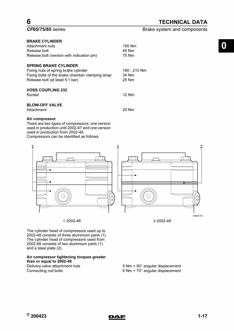
Air compressor
There are two types of compressors: one version used in production until 2002-47 and one version used in production from 2002-48.Compressors can be identified as follows:
The cylinder head of compressors used up to 2002-48 consists of three aluminium parts (1). The cylinder head of compressors used from 2002-48 consists of two aluminium parts (1) and a steel plate (2).
Air compressor tightening torques greater than or equal to 2002-48
Attachment nuts 195 Nm
Release bolt 45 Nm
Release bolt (version with indication pin) 75 Nm
Fixing nuts of spring brake cylinder 180 - 210 Nm
Fixing bolts of the brake chamber clamping strap 34 Nm
Release bolt (at least 5.1 bar) 25 Nm
Socket 12 Nm
Attachment 25 Nm
< 2002-48 2002-48
1 1 2
R600743
Delivery valve attachment nuts 5 Nm + 90 angular displacement
Connecting rod bolts 6 Nm + 70 angular displacement
https://www.truck-manuals.net/
TECHNICAL DATA
1-18 © 200423
Brake system and components
0
ΧΦ65/75/85 series
6
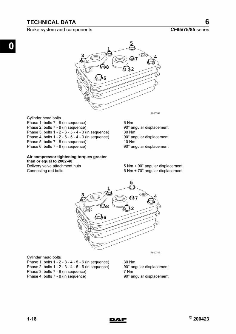
Air compressor tightening torques greater than or equal to 2002-48
R600742
6
2
47
8
31
5
Cylinder head bolts
Phase 1, bolts 7 - 8 (in sequence) 6 Nm
Phase 2, bolts 7 - 8 (in sequence) 90 angular displacement
Phase 3, bolts 1 - 2 - 6 - 5 - 4 - 3 (in sequence) 30 Nm
Phase 4, bolts 1 - 2 - 6 - 5 - 4 - 3 (in sequence) 90 angular displacement
Phase 5, bolts 7 - 8 (in sequence) 10 Nm
Phase 6, bolts 7 - 8 (in sequence) 90 angular displacement
Delivery valve attachment nuts 5 Nm + 90 angular displacement
Connecting rod bolts 6 Nm + 70 angular displacement
R600742
6
2
47
8
31
5
Cylinder head bolts
Phase 1, bolts 1 - 2 - 3 - 4 - 5 - 6 (in sequence) 30 Nm
Phase 2, bolts 1 - 2 - 3 - 4 - 5 - 6 (in sequence) 90 angular displacement
Phase 3, bolts 7 - 8 (in sequence) 7 Nm
Phase 4, bolts 7 - 8 (in sequence) 90 angular displacement
https://www.truck-manuals.net/
© 200423 1-19
Brake system and components
TECHNICAL DATA
ΧΦ65/75/85 series
6
01.3 LUBRICANTS
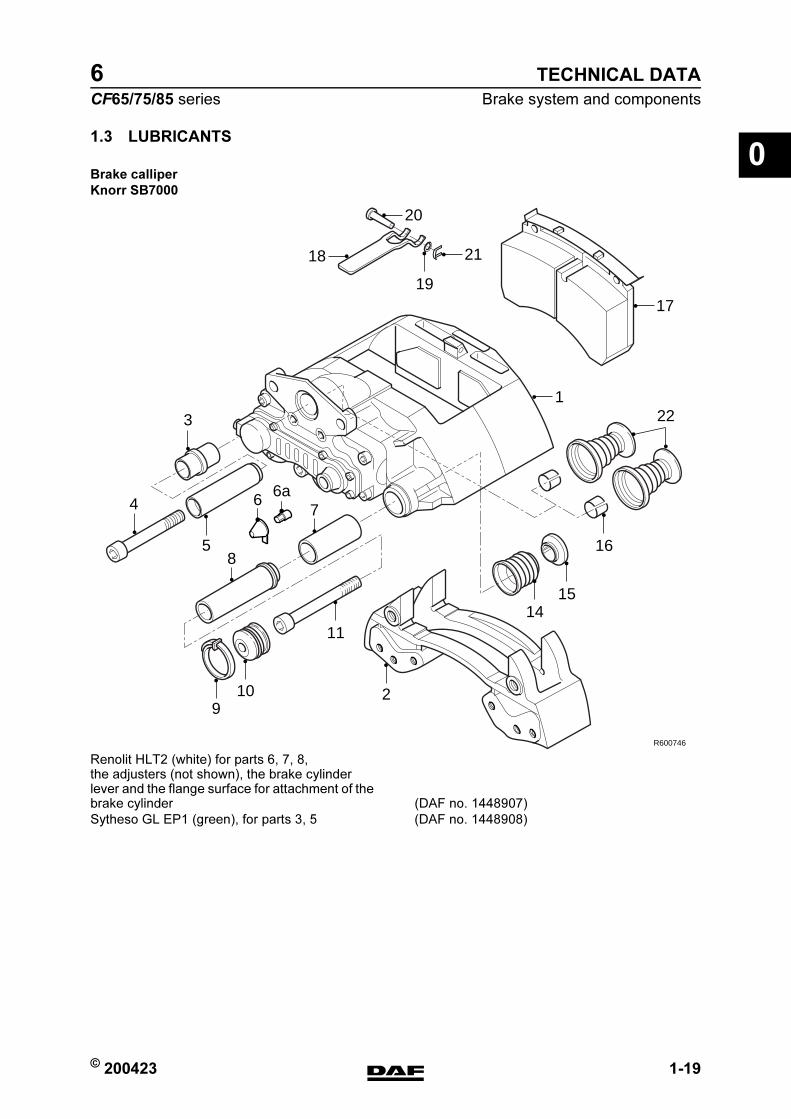
Brake calliper
Knorr SB7000
R600746
18
122
7
19
1114
15
16
109
2
17
20
21
85
4
3
6 6a
Renolit HLT2 (white) for parts 6, 7, 8, the adjusters (not shown), the brake cylinder lever and the flange surface for attachment of the brake cylinder (DAF no. 1448907)
Sytheso GL EP1 (green), for parts 3, 5 (DAF no. 1448908)
https://www.truck-manuals.net/
TECHNICAL DATA
1-20 © 200423
Brake system and components
0
ΧΦ65/75/85 series
6
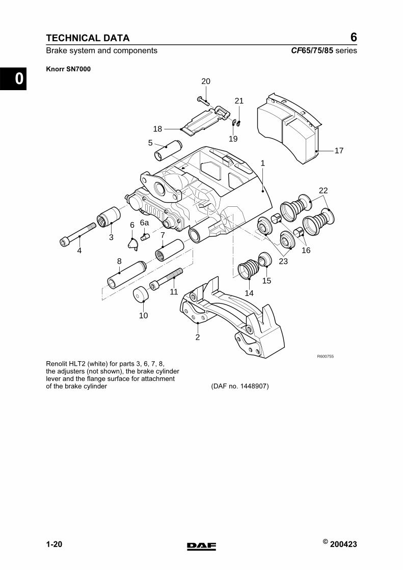
Knorr SN7000
R600755
17
22
2316
18
20
21
5
1
6 6a
7
8
19
15
14
2
11
10
4
3
Renolit HLT2 (white) for parts 3, 6, 7, 8, the adjusters (not shown), the brake cylinderlever and the flange surface for attachment of the brake cylinder (DAF no. 1448907)
https://www.truck-manuals.net/

© 200423 2-1
Braking performance and brake equalisation
TECHNICAL DATA
ΧΦ65/75/85 series
6
02. BRAKING PERFORMANCE AND BRAKE EQUALISATION
2.1 GENERAL
EBS tyre class
The tyre sizes are classified into tyre classes.This tyre class information is necessary to be able to assess the brake presentation, by measurements of brake force.This tyre class information is also necessary for the EBS system to be able to evaluate whether the electric EBS unit is programmed when the tyre size is changed..
Tyre size change in EBS system
If the tyre size is changed in an EBS system and the tyre size of the front and rear axle no longer fall in the same tyre class, the changed tyre sizes must be programmed into the electronic EBS unit.
Tyre class Tyre size
Class 0 215/75 R 17.5
235/75 R 17.5
Class 1 295/60 R 22.5
255/70 R 22.5
315/60 R 22.5
275/70 R 22.5
Class 2 305/70 R 22.5
315/70 R 22.5
385/55 R 22.5
295/80 R 22.5
11 R 22.5
Class 3 385/65 R 22.5
315/80 R 22.5
11.00 R 20
12 R 22.5
12.00 R 20
13 R 22.5
https://www.truck-manuals.net/
TECHNICAL DATA
2-2 © 200423
Braking performance and brake equalisation
0
ΧΦ65/75/85 series
6
Tyre size change in EBS 2 system
If the tyre size is changed in an EBS 2 system and the tyre size of the front and rear axle no longer fall in the same tyre class, it is not necessary to program the electronic ESB 2 unit because the electronic ESB 2 unit will automatically recognise this change in tyre size.
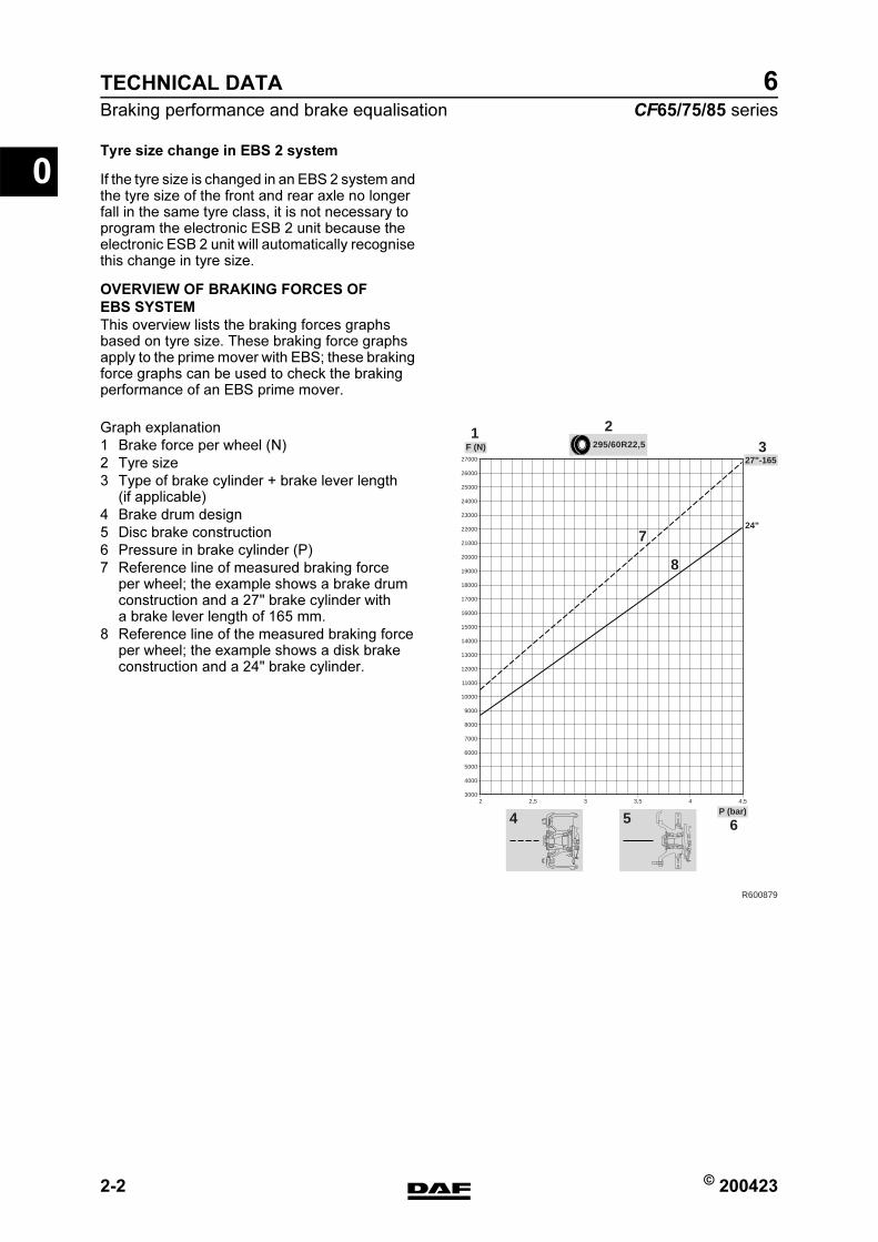
OVERVIEW OF BRAKING FORCES OF
EBS SYSTEM
This overview lists the braking forces graphs based on tyre size. These braking force graphs apply to the prime mover with EBS; these braking force graphs can be used to check the braking performance of an EBS prime mover.
R600879
295/60R22,5
P (bar)
F (N)1 2
3
654
7
8
24"
27"-165
30002 2,5 3 3,5 4 4,5
4000
5000
6000
7000
8000
9000
10000
11000
12000
13000
14000
15000
16000
17000
18000
19000
20000
21000
22000
23000
24000
25000
26000
27000
Graph explanation
1 Brake force per wheel (N)
2 Tyre size
3 Type of brake cylinder + brake lever length (if applicable)
4 Brake drum design
5 Disc brake construction
6 Pressure in brake cylinder (P)
7 Reference line of measured braking force per wheel; the example shows a brake drum construction and a 27" brake cylinder with a brake lever length of 165 mm.
8 Reference line of the measured braking force per wheel; the example shows a disk brake construction and a 24" brake cylinder.
https://www.truck-manuals.net/
© 200423 2-3
Braking performance and brake equalisation
TECHNICAL DATA
ΧΦ65/75/85 series
6
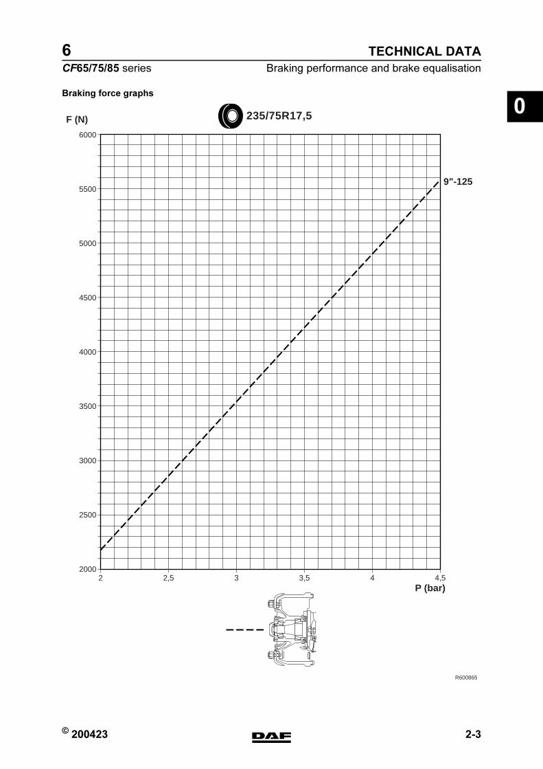
0Braking force graphs
R600865
2 2,5 3 3,5 4 4,5
235/75R17,5
P (bar)
6000
5500
5000
4500
4000
3500
3000
2500
2000
F (N)
9"-125
https://www.truck-manuals.net/

TECHNICAL DATA
2-4 © 200423
Braking performance and brake equalisation
0
ΧΦ65/75/85 series
6
R600866
30002 2,5 3 3,5 4 4,5
4000
5000
6000
7000
8000
9000
10000
11000
12000
13000
14000
15000
16000
17000
18000
19000
20000
21000
22000
23000
24000
25000
26000
27000
295/60R22,5
P (bar)
F (N)
12"
14"
16"
22"
24"
27"-165
24"-165
https://www.truck-manuals.net/

© 200423 2-5
Braking performance and brake equalisation
TECHNICAL DATA
ΧΦ65/75/85 series
6
0
R600867
30002 2,5 3 3,5 4 4,5
4000
5000
6000
7000
8000
9000
10000
11000
12000
13000
14000
15000
16000
17000
18000
19000
20000
21000
22000
23000
24000
25000
26000
27000
255/70R22,5
P (bar)
F (N)
12"
14"
16"
22"
24"
27"-165
24"-165
https://www.truck-manuals.net/

TECHNICAL DATA
2-6 © 200423
Braking performance and brake equalisation
0
ΧΦ65/75/85 series
6
R600868
30002 2,5 3 3,5 4 4,5
4000
5000
6000
7000
8000
9000
10000
11000
12000
13000
14000
15000
16000
17000
18000
19000
20000
21000
22000
23000
24000
25000
26000
27000
315/60R22,5
P (bar)
F (N)
12"
14"
16"
22"
24"
27"-165
24"-165
https://www.truck-manuals.net/
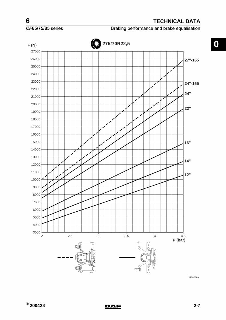
© 200423 2-7
Braking performance and brake equalisation
TECHNICAL DATA
ΧΦ65/75/85 series
6
0
R600869
30002 2,5 3 3,5 4 4,5
4000
5000
6000
7000
8000
9000
10000
11000
12000
13000
14000
15000
16000
17000
18000
19000
20000
21000
22000
23000
24000
25000
26000
27000
275/70R22,5
P (bar)
F (N)
12"
14"
16"
22"
24"
27"-165
24"-165
https://www.truck-manuals.net/
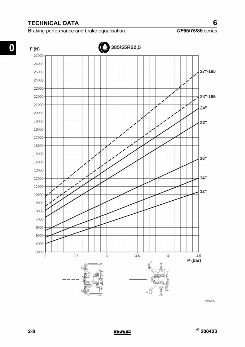
TECHNICAL DATA
2-8 © 200423
Braking performance and brake equalisation
0
ΧΦ65/75/85 series
6
R600870
30002 2,5 3 3,5 4 4,5
4000
5000
6000
7000
8000
9000
10000
11000
12000
13000
14000
15000
16000
17000
18000
19000
20000
21000
22000
23000
24000
25000
26000
27000
385/55R22,5
P (bar)
F (N)
12"
14"
16"
22"
24"
27"-165
24"-165
https://www.truck-manuals.net/
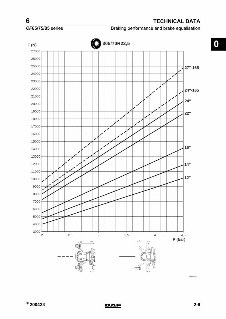
© 200423 2-9
Braking performance and brake equalisation
TECHNICAL DATA
ΧΦ65/75/85 series
6
0
R600871
30002 2,5 3 3,5 4 4,5
4000
5000
6000
7000
8000
9000
10000
11000
12000
13000
14000
15000
16000
17000
18000
19000
20000
21000
22000
23000
24000
25000
26000
27000
305/70R22,5
P (bar)
F (N)
12"
14"
16"
22"
24"
27"-165
24"-165
https://www.truck-manuals.net/
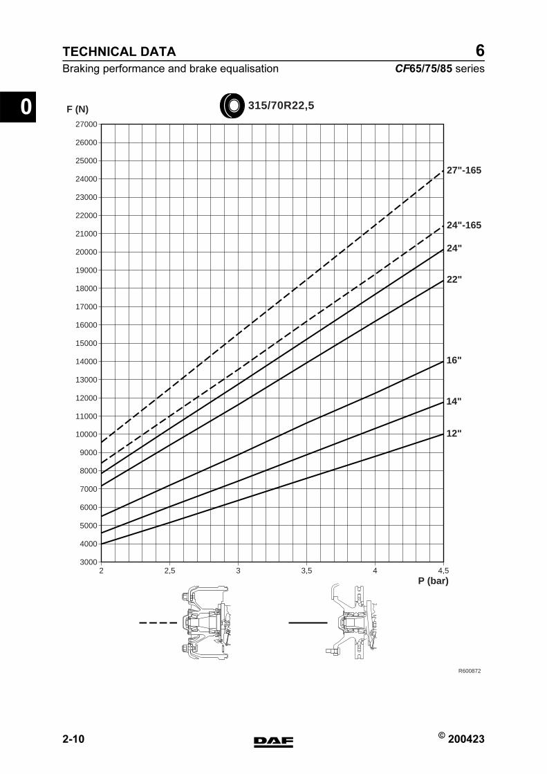
TECHNICAL DATA
2-10 © 200423
Braking performance and brake equalisation
0
ΧΦ65/75/85 series
6
R600872
30002 2,5 3 3,5 4 4,5
4000
5000
6000
7000
8000
9000
10000
11000
12000
13000
14000
15000
16000
17000
18000
19000
20000
21000
22000
23000
24000
25000
26000
27000
315/70R22,5
P (bar)
F (N)
12"
14"
16"
22"
24"
27"-165
24"-165
https://www.truck-manuals.net/
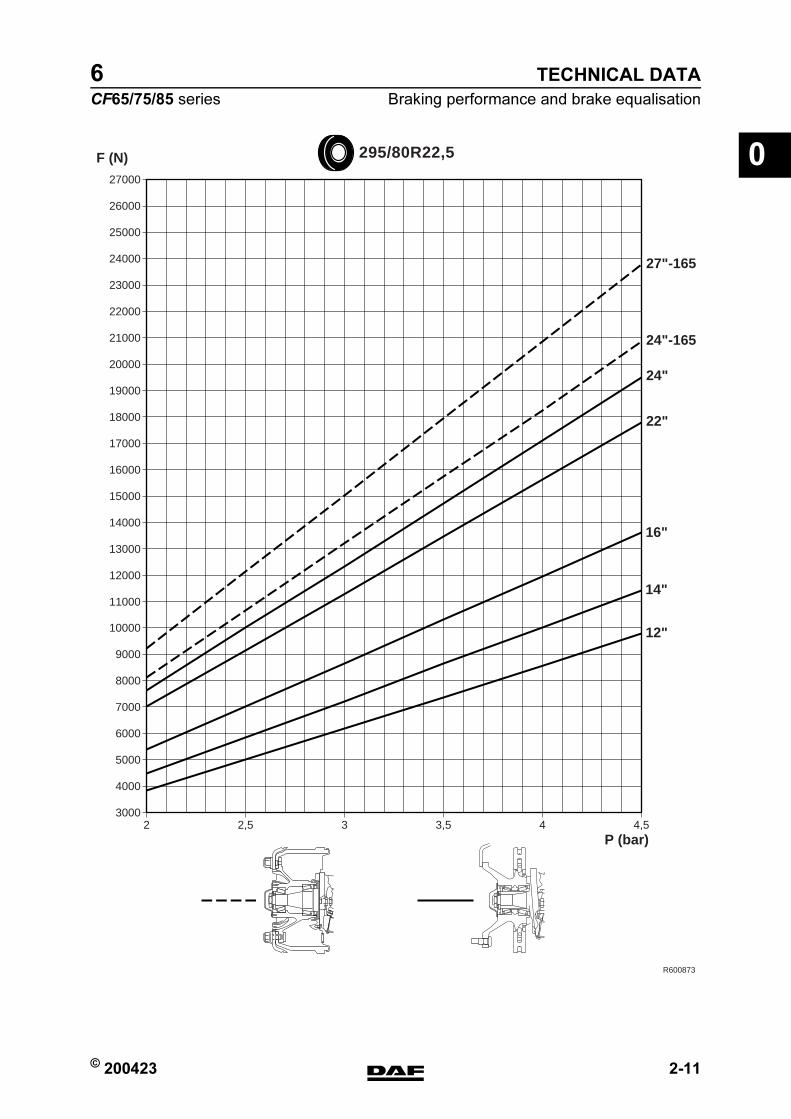
© 200423 2-11
Braking performance and brake equalisation
TECHNICAL DATA
ΧΦ65/75/85 series
6
0
R600873
30002 2,5 3 3,5 4 4,5
4000
5000
6000
7000
8000
9000
10000
11000
12000
13000
14000
15000
16000
17000
18000
19000
20000
21000
22000
23000
24000
25000
26000
27000
295/80R22,5
P (bar)
F (N)
12"
14"
16"
22"
24"
27"-165
24"-165
https://www.truck-manuals.net/

TECHNICAL DATA
2-12 © 200423
Braking performance and brake equalisation
0
ΧΦ65/75/85 series
6
R600874
30002 2,5 3 3,5 4 4,5
4000
5000
6000
7000
8000
9000
10000
11000
12000
13000
14000
15000
16000
17000
18000
19000
20000
21000
22000
23000
24000
25000
26000
27000
11R22,5
P (bar)
F (N)
12"
14"
16"
22"
24"
27"-165
24"-165
https://www.truck-manuals.net/
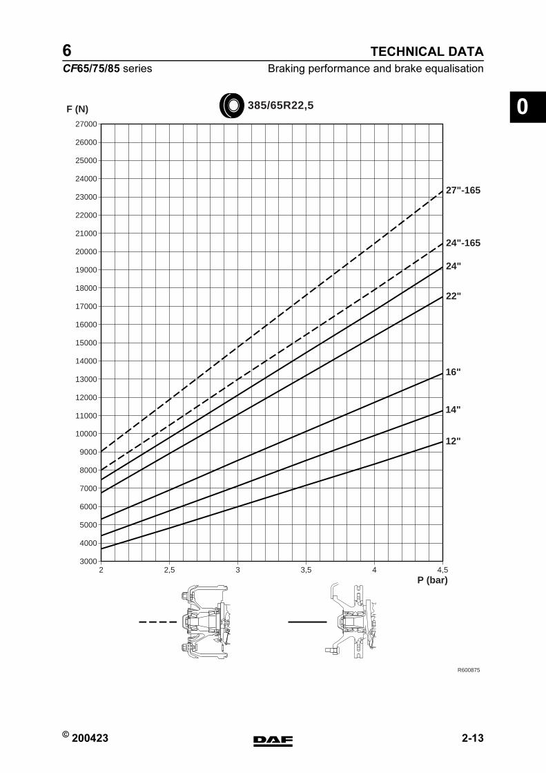
© 200423 2-13
Braking performance and brake equalisation
TECHNICAL DATA
ΧΦ65/75/85 series
6
0
R600875
30002 2,5 3 3,5 4 4,5
4000
5000
6000
7000
8000
9000
10000
11000
12000
13000
14000
15000
16000
17000
18000
19000
20000
21000
22000
23000
24000
25000
26000
27000
F (N) 385/65R22,5
P (bar)
12"
14"
16"
22"
24"
27"-165
24"-165
https://www.truck-manuals.net/
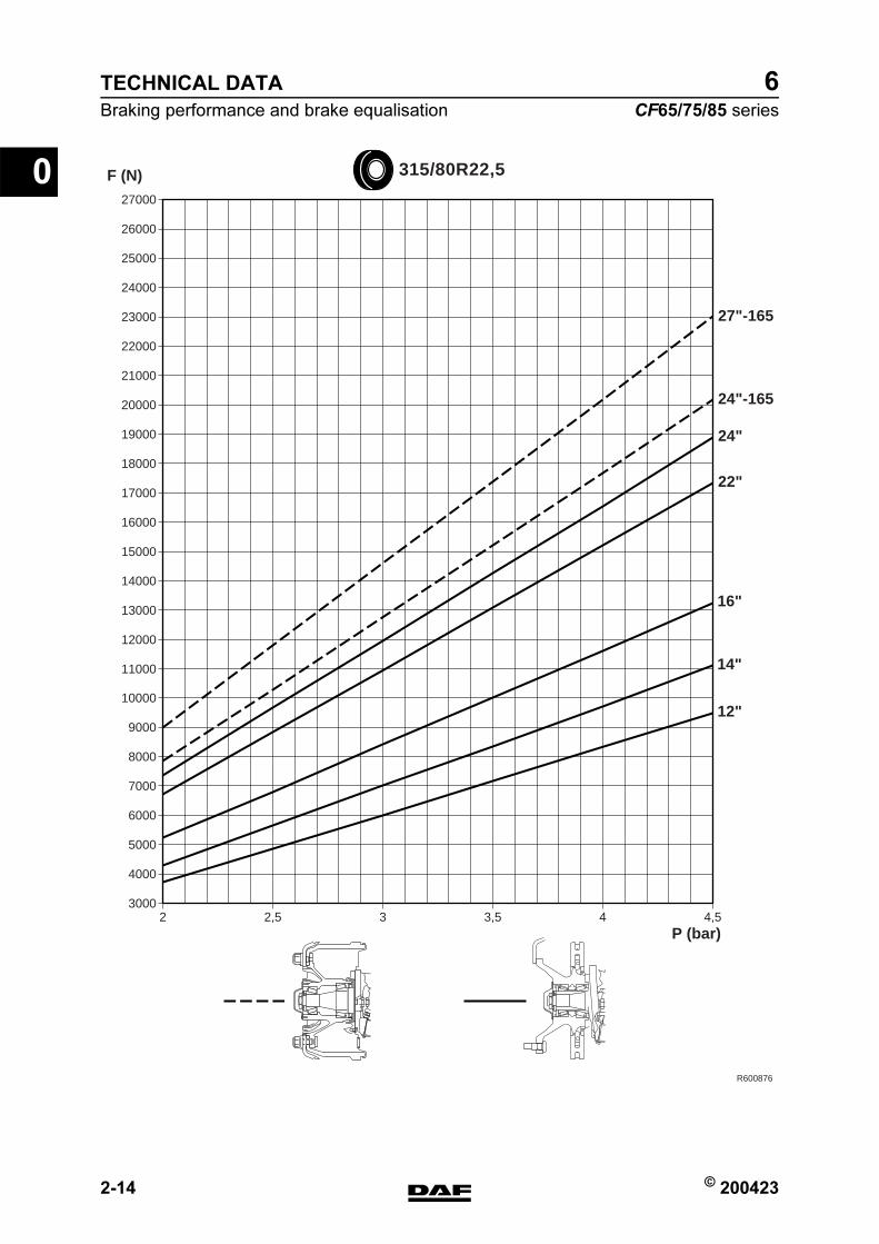
TECHNICAL DATA
2-14 © 200423
Braking performance and brake equalisation
0
ΧΦ65/75/85 series
6
R600876
30002 2,5 3 3,5 4 4,5
4000
5000
6000
7000
8000
9000
10000
11000
12000
13000
14000
15000
16000
17000
18000
19000
20000
21000
22000
23000
24000
25000
26000
27000
315/80R22,5
P (bar)
F (N)
12"
14"
16"
22"
24"
27"-165
24"-165
https://www.truck-manuals.net/
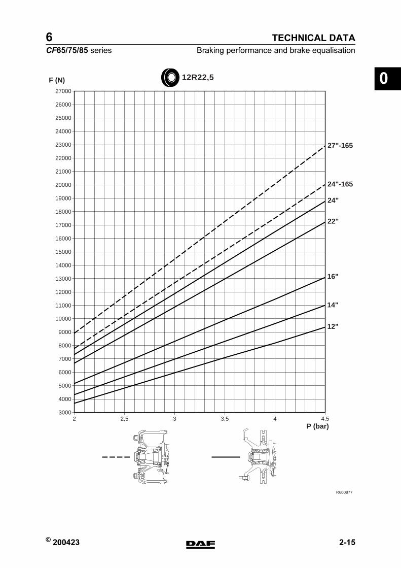
© 200423 2-15
Braking performance and brake equalisation
TECHNICAL DATA
ΧΦ65/75/85 series
6
0
R600877
30002 2,5 3 3,5 4 4,5
4000
5000
6000
7000
8000
9000
10000
11000
12000
13000
14000
15000
16000
17000
18000
19000
20000
21000
22000
23000
24000
25000
26000
27000
12R22,5
P (bar)
F (N)
12"
14"
16"
22"
24"
27"-165
24"-165
https://www.truck-manuals.net/

TECHNICAL DATA
2-16 © 200423
Braking performance and brake equalisation
0
ΧΦ65/75/85 series
6
R600878
30002 2,5 3 3,5 4 4,5
4000
5000
6000
7000
8000
9000
10000
11000
12000
13000
14000
15000
16000
17000
18000
19000
20000
21000
22000
23000
24000
25000
26000
27000
13R22,5
P (bar)
F (N)
12"
14"
16"
22"
24"
27"-165
24"-165
https://www.truck-manuals.net/
6
CF65/75/85 series Contents
DIAGNOSTICS
1
CONTENTS
Page Date
1. DISC BRAKE CONSTRUCTION 1-1 200324. . . . . . . . . . . . . . . . . . . . . . . . . . . . . . . . . . . . . . . . . . . . .1.1 Fault-finding table 1-1 200324. . . . . . . . . . . . . . . . . . . . . . . . . . . . . . . . . . . . . . . . . . . . . . . . . . . . .
2. DRUM BRAKE CONSTRUCTION 2-1 200324. . . . . . . . . . . . . . . . . . . . . . . . . . . . . . . . . . . . . . . . . . . .2.1 Fault-finding table 2-1 200324. . . . . . . . . . . . . . . . . . . . . . . . . . . . . . . . . . . . . . . . . . . . . . . . . . . . .
1
� 200324https://www.truck-manuals.net/
6DIAGNOSTICS
Contents CF65/75/85 series
2
1
� 200324https://www.truck-manuals.net/
6
CF65/75/85 series Disc brake construction
DIAGNOSTICS
1-1
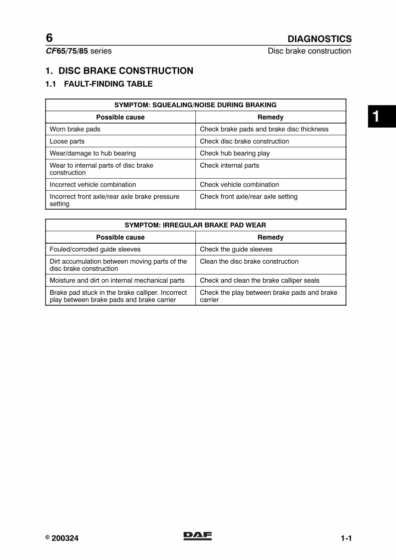
1. DISC BRAKE CONSTRUCTION
1.1 FAULT-FINDING TABLE
SYMPTOM: SQUEALING/NOISE DURING BRAKING
Possible cause Remedy
Worn brake pads Check brake pads and brake disc thickness
Loose parts Check disc brake construction
Wear/damage to hub bearing Check hub bearing play
Wear to internal parts of disc brakeconstruction
Check internal parts
Incorrect vehicle combination Check vehicle combination
Incorrect front axle/rear axle brake pressuresetting
Check front axle/rear axle setting
SYMPTOM: IRREGULAR BRAKE PAD WEAR
Possible cause Remedy
Fouled/corroded guide sleeves Check the guide sleeves
Dirt accumulation between moving parts of thedisc brake construction
Clean the disc brake construction
Moisture and dirt on internal mechanical parts Check and clean the brake calliper seals
Brake pad stuck in the brake calliper. Incorrectplay between brake pads and brake carrier
Check the play between brake pads and brakecarrier
1
� 200324https://www.truck-manuals.net/
6DIAGNOSTICS
Disc brake construction CF65/75/85 series
1-2
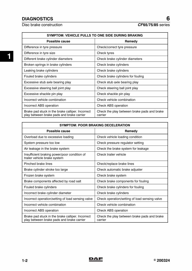
SYMPTOM: VEHICLE PULLS TO ONE SIDE DURING BRAKING
Possible cause Remedy
Difference in tyre pressure Check/correct tyre pressure
Difference in tyre size Check tyres
Different brake cylinder diameters Check brake cylinder diameters
Broken springs in brake cylinders Check brake cylinders
Leaking brake cylinders Check brake cylinders
Fouled brake cylinders Check brake cylinders for fouling
Excessive stub axle bearing play Check stub axle bearing play
Excessive steering ball joint play Check steering ball joint play
Excessive shackle pin play Check shackle pin play
Incorrect vehicle combination Check vehicle combination
Incorrect ABS operation Check ABS operation
Brake pad stuck in the brake calliper. Incorrectplay between brake pads and brake carrier
Check the play between brake pads and brakecarrier
SYMPTOM: POOR BRAKING DECELERATION
Possible cause Remedy
Overload due to excessive loading Check vehicle loading condition
System pressure too low Check pressure regulator setting
Air leakage in the brake system Check the brake system for leakage
Insufficient braking power/poor condition oftrailer vehicle brake system
Check trailer vehicle
Pinched brake lines Check/replace brake lines
Brake cylinder stroke too large Check automatic brake adjuster
Frozen brake system Check brake system
Brake components affected by road salt Check brake components for fouling
Fouled brake cylinders Check brake cylinders for fouling
Incorrect brake cylinder diameter Check brake cylinders
Incorrect operation/setting of load sensing valve Check operation/setting of load sensing valve
Incorrect vehicle combination Check vehicle combination
Incorrect ABS operation Check ABS operation
Brake pad stuck in the brake calliper. Incorrectplay between brake pads and brake carrier
Check the play between brake pads and brakecarrier
1
� 200324https://www.truck-manuals.net/
6
CF65/75/85 series Disc brake construction
DIAGNOSTICS
1-3
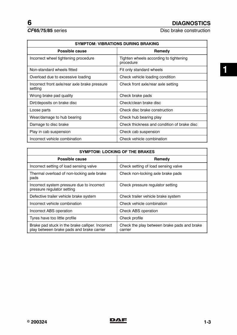
SYMPTOM: VIBRATIONS DURING BRAKING
Possible cause Remedy
Incorrect wheel tightening procedure Tighten wheels according to tighteningprocedure
Non-standard wheels fitted Fit only standard wheels
Overload due to excessive loading Check vehicle loading condition
Incorrect front axle/rear axle brake pressuresetting
Check front axle/rear axle setting
Wrong brake pad quality Check brake pads
Dirt/deposits on brake disc Check/clean brake disc
Loose parts Check disc brake construction
Wear/damage to hub bearing Check hub bearing play
Damage to disc brake Check thickness and condition of brake disc
Play in cab suspension Check cab suspension
Incorrect vehicle combination Check vehicle combination
SYMPTOM: LOCKING OF THE BRAKES
Possible cause Remedy
Incorrect setting of load sensing valve Check setting of load sensing valve
Thermal overload of non-locking axle brakepads
Check non-locking axle brake pads
Incorrect system pressure due to incorrectpressure regulator setting
Check pressure regulator setting
Defective trailer vehicle brake system Check trailer vehicle brake system
Incorrect vehicle combination Check vehicle combination
Incorrect ABS operation Check ABS operation
Tyres have too little profile Check profile
Brake pad stuck in the brake calliper. Incorrectplay between brake pads and brake carrier
Check the play between brake pads and brakecarrier
1
� 200324https://www.truck-manuals.net/

6DIAGNOSTICS
Disc brake construction CF65/75/85 series
1-4
SYMPTOM: INCREASED BRAKE PAD WEAR
Possible cause Remedy
Overload due to excessive loading Check vehicle loading condition
Incorrect setting of load sensing valve Check setting of load sensing valve
Incorrect vehicle combination or front axle/rearaxle combination
Check vehicle combination or front axle/rearaxle combination
Defective trailer vehicle brake system Check trailer vehicle brake system
Air pressure in spring brake cylinders too lowduring driving, dragging brakes
Check air pressure in spring brake cylinderswith the parking brake valve in the drivingposition
Dragging brakes because parking brake is notreleased
Check release of parking brake
Dirt under foot brake valve/floor mat too high Check for free movement of foot brake valve
Contaminated/blocked brake valve vents Check valve vents
Brake pad stuck in the brake calliper. Incorrectplay between brake pads and brake carrier
Check the play between brake pads and brakecarrier
Incorrect setting of the trailer vehicle controlvalve/trailer vehicle reaction valve
Check setting of the trailer vehicle controlvalve/trailer vehicle reaction valve
SYMPTOM: DRAGGING BRAKES
Possible cause Remedy
Leaking foot brake valve to circuit 1 and/or 2 Check the foot brake valve for leaks
Dirt/deposits in brake calliper of disc brake Check freedom of movement of brake calliper
Brake pads set too tightly Check minimum brake pad play
Air pressure in spring brake cylinders too lowduring driving
Check output pressure of thedouble-check relay valveCheck four-circuit safety valve forcontaminationCheck output pressure of the parking brakevalve in the driving position
Output supply pressure from trailer vehiclecontrol valve to trailer/semi-trailer too low
Check output supply pressure of the trailervehicle control valve
Dirt under foot brake valve/floor mat too high Check for free movement of foot brake valve
Contaminated/blocked brake valve vents Check valve vents
Brake pad stuck in the brake calliper. Incorrectplay between brake pads and brake carrier
Check the play between brake pads and brakecarrier
1
� 200324https://www.truck-manuals.net/
6
CF65/75/85 series Drum brake construction
DIAGNOSTICS
2-1
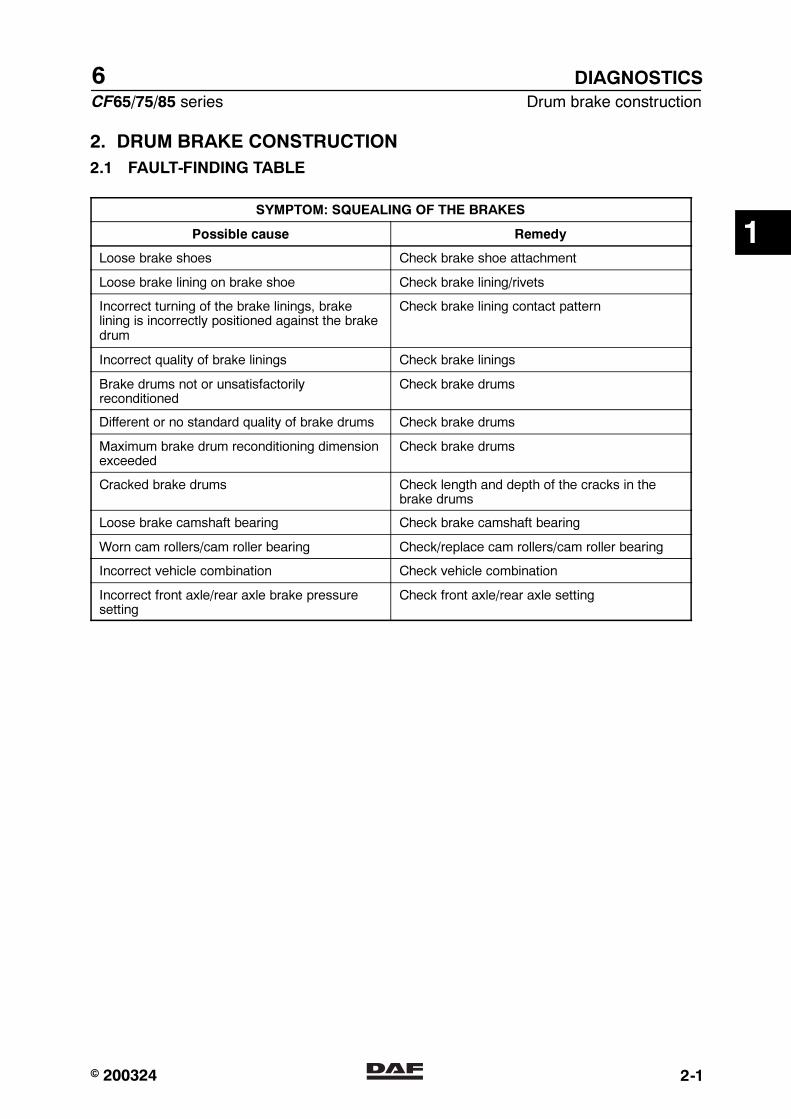
2. DRUM BRAKE CONSTRUCTION
2.1 FAULT-FINDING TABLE
SYMPTOM: SQUEALING OF THE BRAKES
Possible cause Remedy
Loose brake shoes Check brake shoe attachment
Loose brake lining on brake shoe Check brake lining/rivets
Incorrect turning of the brake linings, brakelining is incorrectly positioned against the brakedrum
Check brake lining contact pattern
Incorrect quality of brake linings Check brake linings
Brake drums not or unsatisfactorilyreconditioned
Check brake drums
Different or no standard quality of brake drums Check brake drums
Maximum brake drum reconditioning dimensionexceeded
Check brake drums
Cracked brake drums Check length and depth of the cracks in thebrake drums
Loose brake camshaft bearing Check brake camshaft bearing
Worn cam rollers/cam roller bearing Check/replace cam rollers/cam roller bearing
Incorrect vehicle combination Check vehicle combination
Incorrect front axle/rear axle brake pressuresetting
Check front axle/rear axle setting
1
� 200324https://www.truck-manuals.net/

6DIAGNOSTICS
Drum brake construction CF65/75/85 series
2-2
SYMPTOM: VEHICLE PULLS TO ONE SIDE DURING BRAKING
Possible cause Remedy
Worn brake lining/drum Check brake lining/drum
Difference in tyre pressure Check/correct tyre pressure
Difference in tyre size Check tyres
Different quality of brake linings Check brake linings
Incorrect turning of the brake linings, brakelining is incorrectly positioned against the brakedrum
Check brake lining contact pattern
Different brake shoe return springs, too slack Check brake shoe return springs
Brake linings affected by grease or oil Check seals and/or cam rollers for excessgrease or oil
Damaged brake lining surface Check brake linings
Non-tapered brake linings Check brake linings
Different brake cylinder diameters Check brake cylinder diameters
Broken springs in brake cylinders Check brake cylinders
Leaking brake cylinders Check brake cylinders
Fouled brake cylinders Check brake cylinders for fouling
Defective brake adjuster(s) Check automatic brake adjuster
Incorrectly set brake adjuster travel Check brake adjuster travel setting
Brake camshaft freedom of movement Check brake camshaft freedom of movement
Excessive stub axle bearing play Check stub axle bearing play
Excessive steering ball joint play Check steering ball joint play
Excessive shackle pin play Check shackle pin play
Incorrect vehicle combination Check vehicle combination
Incorrect ABS operation Check ABS operation
1
� 200324https://www.truck-manuals.net/

6
CF65/75/85 series Drum brake construction
DIAGNOSTICS
2-3
SYMPTOM: POOR BRAKING DECELERATION
Possible cause Remedy
Overload due to excessive loading Check vehicle loading condition
System pressure too low Check pressure regulator setting
Air leaks in the brake system Check the brake system for leaks
Insufficient braking power/poor condition oftrailer vehicle brake system
Check trailer vehicle
Pinched brake lines Check/replace brake lines
Brake cylinder stroke too large Check automatic brake adjuster
Frozen brake system Check brake system
Brake components affected by road salt Check brake components for fouling
Fouled brake cylinders Check brake cylinders for fouling
Incorrect brake cylinder diameter Check brake cylinders
Brake linings affected by grease or oil Check seals and/or cam rollers for excessgrease or oil
Incorrect turning of the brake linings, brakelining is incorrectly positioned against the brakedrum
Check brake lining contact pattern
Damaged brake lining surface Check brake linings
Poor quality of brake linings Check brake linings
Glazed brake linings Check brake linings
Damaged brake shoes Check brake shoes
Seized brake shoe bearing Check brake shoe bearing
Loose brake camshaft bearing Check brake camshaft bearing
Worn cam rollers/cam roller bearing Check cam rollers/cam roller bearing
Incorrect operation/setting of load sensing valve Check operation/setting of load sensing valve
Incorrect vehicle combination Check vehicle combination
Incorrect ABS operation Check ABS operation
1
� 200324https://www.truck-manuals.net/
6DIAGNOSTICS
Drum brake construction CF65/75/85 series
2-4
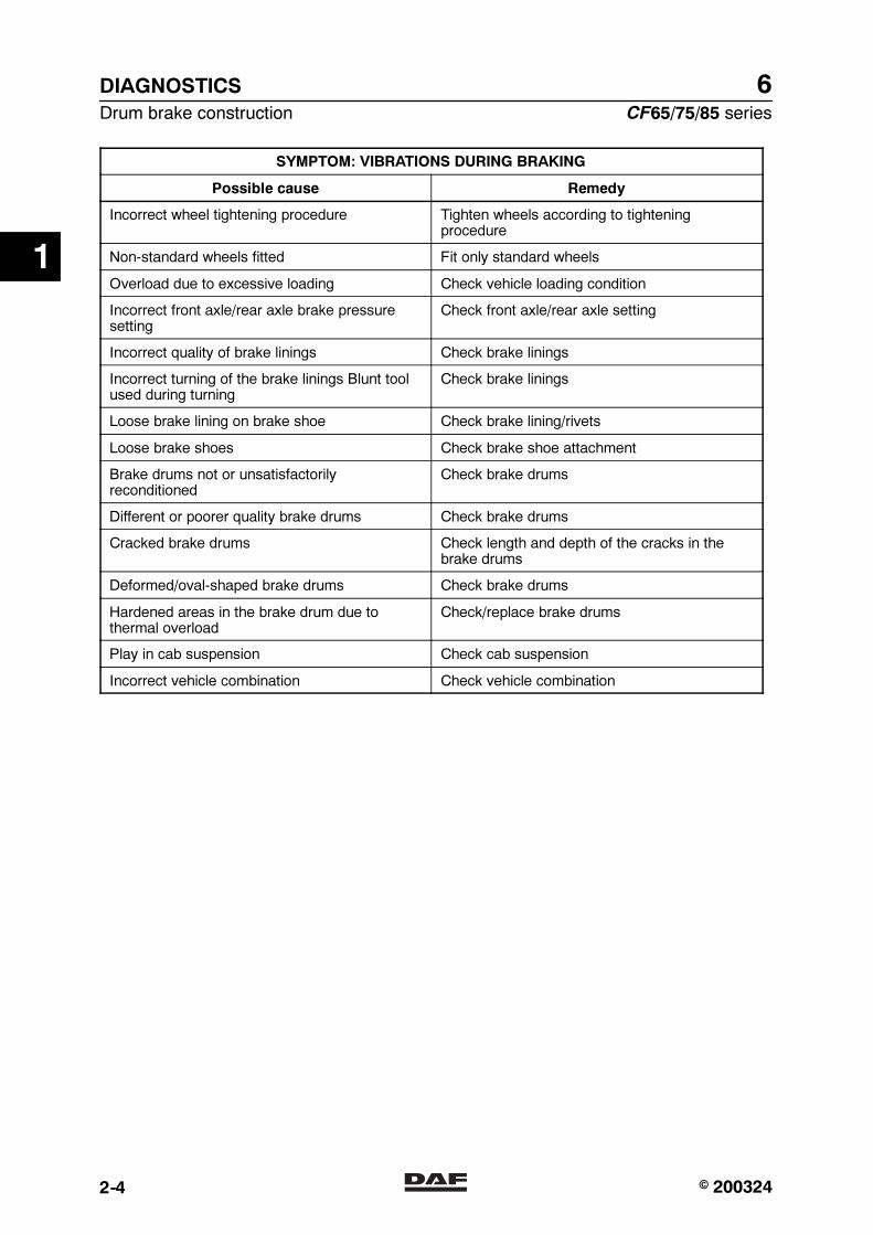
SYMPTOM: VIBRATIONS DURING BRAKING
Possible cause Remedy
Incorrect wheel tightening procedure Tighten wheels according to tighteningprocedure
Non-standard wheels fitted Fit only standard wheels
Overload due to excessive loading Check vehicle loading condition
Incorrect front axle/rear axle brake pressuresetting
Check front axle/rear axle setting
Incorrect quality of brake linings Check brake linings
Incorrect turning of the brake linings Blunt toolused during turning
Check brake linings
Loose brake lining on brake shoe Check brake lining/rivets
Loose brake shoes Check brake shoe attachment
Brake drums not or unsatisfactorilyreconditioned
Check brake drums
Different or poorer quality brake drums Check brake drums
Cracked brake drums Check length and depth of the cracks in thebrake drums
Deformed/oval-shaped brake drums Check brake drums
Hardened areas in the brake drum due tothermal overload
Check/replace brake drums
Play in cab suspension Check cab suspension
Incorrect vehicle combination Check vehicle combination
1
� 200324https://www.truck-manuals.net/
6
CF65/75/85 series Drum brake construction
DIAGNOSTICS
2-5
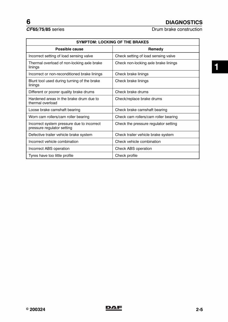
SYMPTOM: LOCKING OF THE BRAKES
Possible cause Remedy
Incorrect setting of load sensing valve Check setting of load sensing valve
Thermal overload of non-locking axle brakelinings
Check non-locking axle brake linings
Incorrect or non-reconditioned brake linings Check brake linings
Blunt tool used during turning of the brakelinings
Check brake linings
Different or poorer quality brake drums Check brake drums
Hardened areas in the brake drum due tothermal overload
Check/replace brake drums
Loose brake camshaft bearing Check brake camshaft bearing
Worn cam rollers/cam roller bearing Check cam rollers/cam roller bearing
Incorrect system pressure due to incorrectpressure regulator setting
Check the pressure regulator setting
Defective trailer vehicle brake system Check trailer vehicle brake system
Incorrect vehicle combination Check vehicle combination
Incorrect ABS operation Check ABS operation
Tyres have too little profile Check profile
1
� 200324https://www.truck-manuals.net/

6DIAGNOSTICS
Drum brake construction CF65/75/85 series
2-6
SYMPTOM: INCREASED BRAKE LINING WEAR
Possible cause Remedy
Overload due to excessive loading Check vehicle loading condition
Incorrect foot brake valve stop bolt setting(residual pressure)
Check foot brake valve setting
Incorrect setting of load sensing valve Check setting of load sensing valve
Incorrect vehicle combination or front axle/rearaxle combination
Check vehicle combination or front axle/rearaxle combination
Defective trailer vehicle brake system Check trailer vehicle brake system
Highly contaminated brakes, seized brake shoepivot points
Check brake shoe freedom of movement, cleanbrakes
Different/incorrect quality of brake linings Check brake linings
Return spring too slack or broken Check return spring
Defective brake adjuster Check automatic brake adjuster
Cracked brake drums Check length and depth of the cracks in thebrake drums
Air pressure in spring brake cylinders too lowduring driving, dragging brakes
Check air pressure in spring brake cylinderswith the parking brake valve in the drivingposition
Dragging brakes because parking brake is notreleased
Check release of parking brake
Dirt under foot brake valve/floor mat too high Check for free movement of foot brake valve
Contaminated/blocked brake valve vents Check valve vents
1
� 200324https://www.truck-manuals.net/
6
CF65/75/85 series Drum brake construction
DIAGNOSTICS
2-7
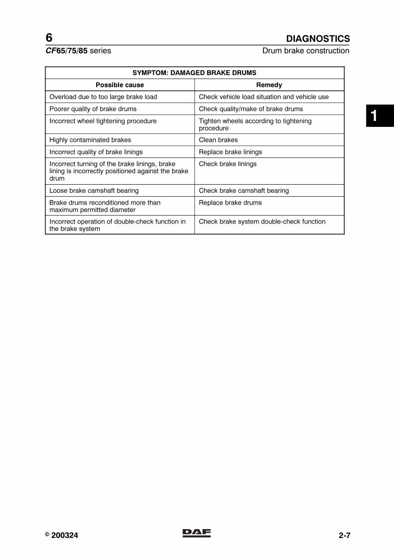
SYMPTOM: DAMAGED BRAKE DRUMS
Possible cause Remedy
Overload due to too large brake load Check vehicle load situation and vehicle use
Poorer quality of brake drums Check quality/make of brake drums
Incorrect wheel tightening procedure Tighten wheels according to tighteningprocedure
Highly contaminated brakes Clean brakes
Incorrect quality of brake linings Replace brake linings
Incorrect turning of the brake linings, brakelining is incorrectly positioned against the brakedrum
Check brake linings
Loose brake camshaft bearing Check brake camshaft bearing
Brake drums reconditioned more thanmaximum permitted diameter
Replace brake drums
Incorrect operation of double-check function inthe brake system
Check brake system double-check function
1
� 200324https://www.truck-manuals.net/
6DIAGNOSTICS
Drum brake construction CF65/75/85 series
2-8
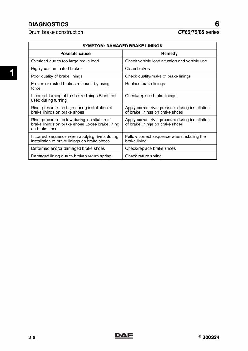
SYMPTOM: DAMAGED BRAKE LININGS
Possible cause Remedy
Overload due to too large brake load Check vehicle load situation and vehicle use
Highly contaminated brakes Clean brakes
Poor quality of brake linings Check quality/make of brake linings
Frozen or rusted brakes released by usingforce
Replace brake linings
Incorrect turning of the brake linings Blunt toolused during turning
Check/replace brake linings
Rivet pressure too high during installation ofbrake linings on brake shoes
Apply correct rivet pressure during installationof brake linings on brake shoes
Rivet pressure too low during installation ofbrake linings on brake shoes Loose brake liningon brake shoe
Apply correct rivet pressure during installationof brake linings on brake shoes
Incorrect sequence when applying rivets duringinstallation of brake linings on brake shoes
Follow correct sequence when installing thebrake lining
Deformed and/or damaged brake shoes Check/replace brake shoes
Damaged lining due to broken return spring Check return spring
1
� 200324https://www.truck-manuals.net/
6
CF65/75/85 series Drum brake construction
DIAGNOSTICS
2-9
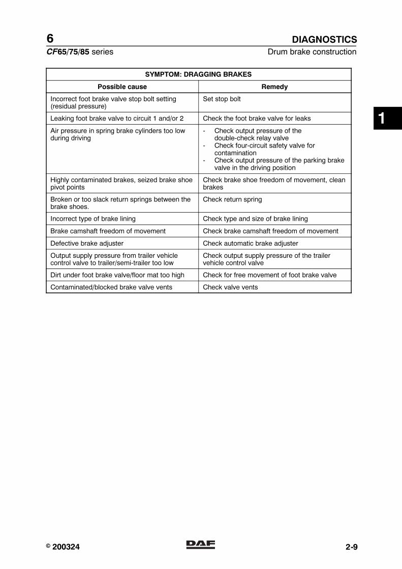
SYMPTOM: DRAGGING BRAKES
Possible cause Remedy
Incorrect foot brake valve stop bolt setting(residual pressure)
Set stop bolt
Leaking foot brake valve to circuit 1 and/or 2 Check the foot brake valve for leaks
Air pressure in spring brake cylinders too lowduring driving
- Check output pressure of thedouble-check relay valve
- Check four-circuit safety valve forcontamination
- Check output pressure of the parking brakevalve in the driving position
Highly contaminated brakes, seized brake shoepivot points
Check brake shoe freedom of movement, cleanbrakes
Broken or too slack return springs between thebrake shoes.
Check return spring
Incorrect type of brake lining Check type and size of brake lining
Brake camshaft freedom of movement Check brake camshaft freedom of movement
Defective brake adjuster Check automatic brake adjuster
Output supply pressure from trailer vehiclecontrol valve to trailer/semi-trailer too low
Check output supply pressure of the trailervehicle control valve
Dirt under foot brake valve/floor mat too high Check for free movement of foot brake valve
Contaminated/blocked brake valve vents Check valve vents
1
� 200324https://www.truck-manuals.net/
6DIAGNOSTICS
Drum brake construction CF65/75/85 series
2-10
1
� 200324https://www.truck-manuals.net/

6
CF65/75/85 series Contents
BRAKE DIAGRAMS FOR FULLY PNEUMATIC BRAKE SYSTEM
1
CONTENTS
Page Date
1. GENERAL 1-1 200324. . . . . . . . . . . . . . . . . . . . . . . . . . . . . . . . . . . . . . . . . . . . . . . . . . . . . . . . . . . . . . . .1.1 Brake diagrams 1-1 200324. . . . . . . . . . . . . . . . . . . . . . . . . . . . . . . . . . . . . . . . . . . . . . . . . . . . . . .
2. BRAKE DIAGRAMS FOR FULLY PNEUMATIC BRAKE SYSTEM 2-1 200324. . . . . . . . . . . . . . .2.1 Legend, brake diagrams for the fully pneumatic brake system 2-1 200324. . . . . . . . . . . . . . .2.2 Brake diagrams for fully pneumatic brake system 2-2 200324. . . . . . . . . . . . . . . . . . . . . . . . .
2
� 200324https://www.truck-manuals.net/
6BRAKE DIAGRAMS FOR FULLY PNEUMATIC BRAKE SYSTEM
Contents CF65/75/85 series
2
2
� 200324https://www.truck-manuals.net/

6
CF65/75/85 series General
BRAKE DIAGRAMS FOR FULLY PNEUMATIC BRAKE SYSTEM
1-1
1. GENERAL
1.1 BRAKE DIAGRAMS
Due to the large number of variants for eachvehicle type and for each country, it isimpractical to list all these variants.
A selection is therefore shown which can formthe basis for other variants.
2
� 200324https://www.truck-manuals.net/

6BRAKE DIAGRAMS FOR FULLY PNEUMATIC BRAKE SYSTEM
General CF65/75/85 series
1-2
2
� 200324https://www.truck-manuals.net/
6
CF65/75/85 series Brake diagrams for fully pneumatic brake system
BRAKE DIAGRAMS FOR FULLY PNEUMATIC BRAKE SYSTEM
2-1
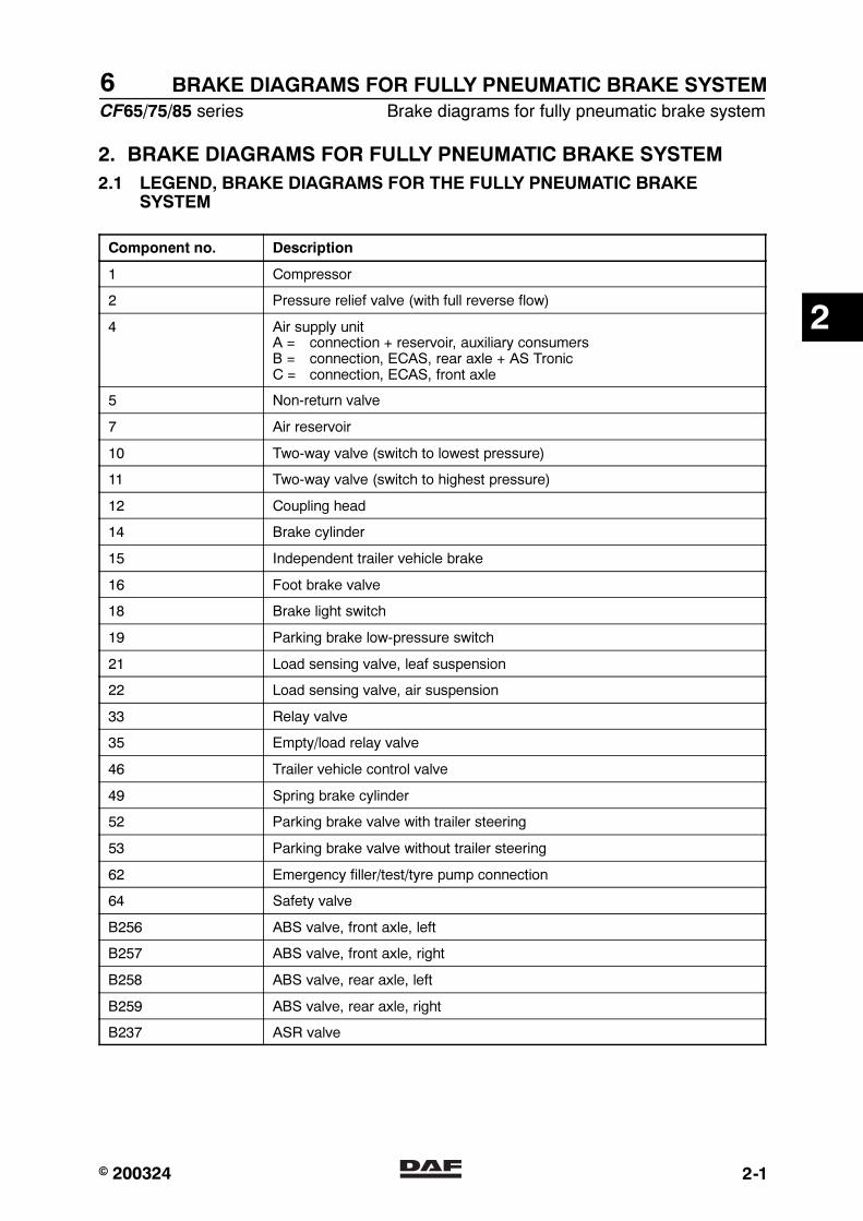
2. BRAKE DIAGRAMS FOR FULLY PNEUMATIC BRAKE SYSTEM
2.1 LEGEND, BRAKE DIAGRAMS FOR THE FULLY PNEUMATIC BRAKESYSTEM
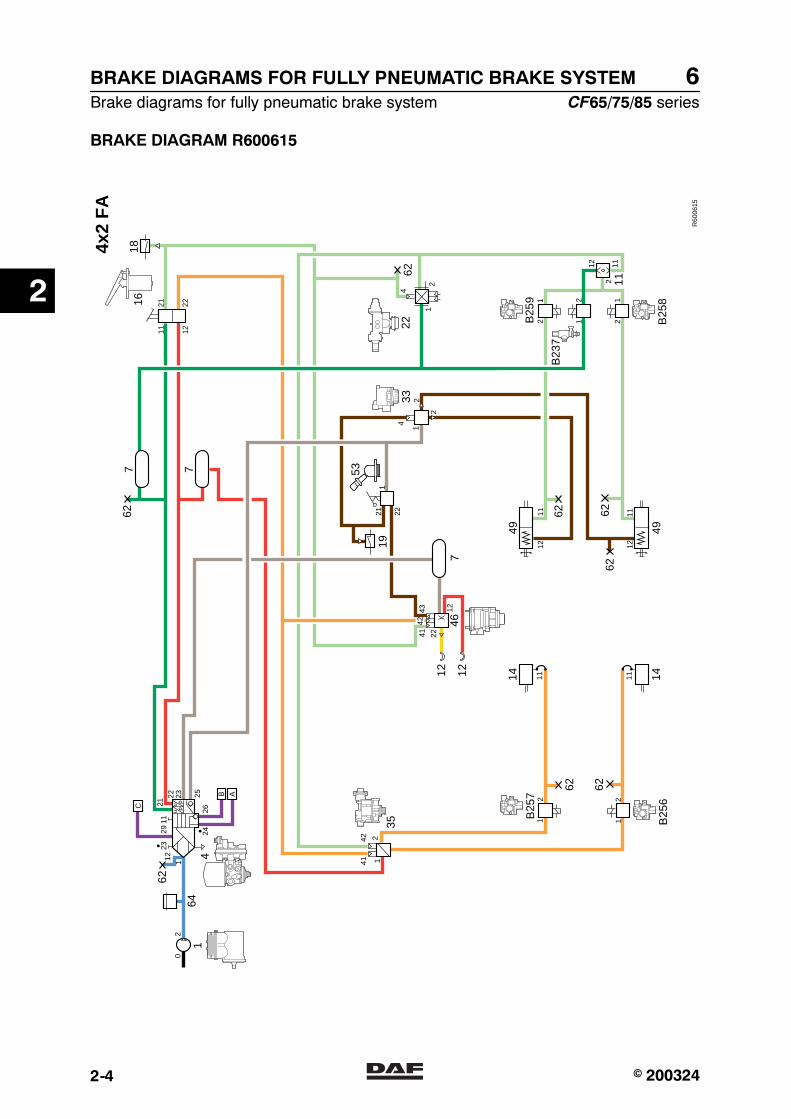
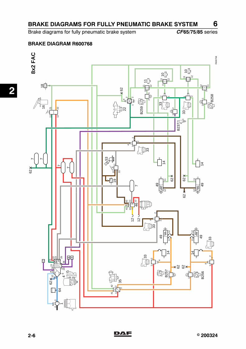
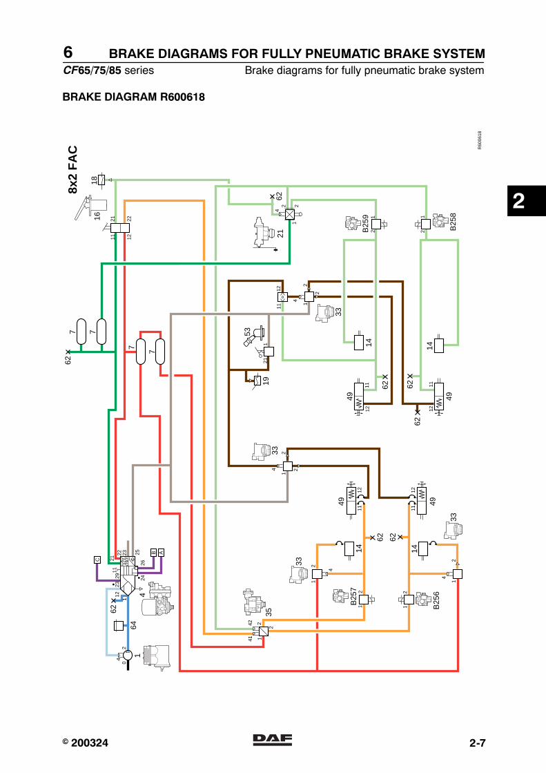
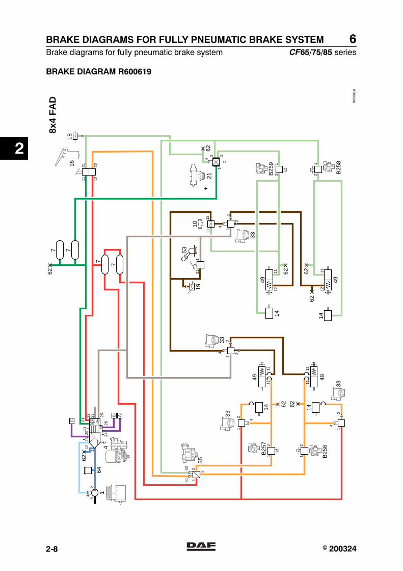
Component no. Description
1 Compressor
2 Pressure relief valve (with full reverse flow)
4 Air supply unitA = connection + reservoir, auxiliary consumersB = connection, ECAS, rear axle + AS TronicC = connection, ECAS, front axle
5 Non-return valve
7 Air reservoir
10 Two-way valve (switch to lowest pressure)
11 Two-way valve (switch to highest pressure)
12 Coupling head
14 Brake cylinder
15 Independent trailer vehicle brake
16 Foot brake valve
18 Brake light switch
19 Parking brake low-pressure switch
21 Load sensing valve, leaf suspension
22 Load sensing valve, air suspension
33 Relay valve
35 Empty/load relay valve
46 Trailer vehicle control valve
49 Spring brake cylinder
52 Parking brake valve with trailer steering
53 Parking brake valve without trailer steering
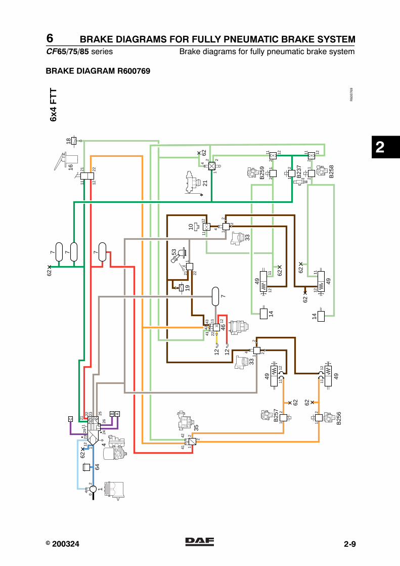
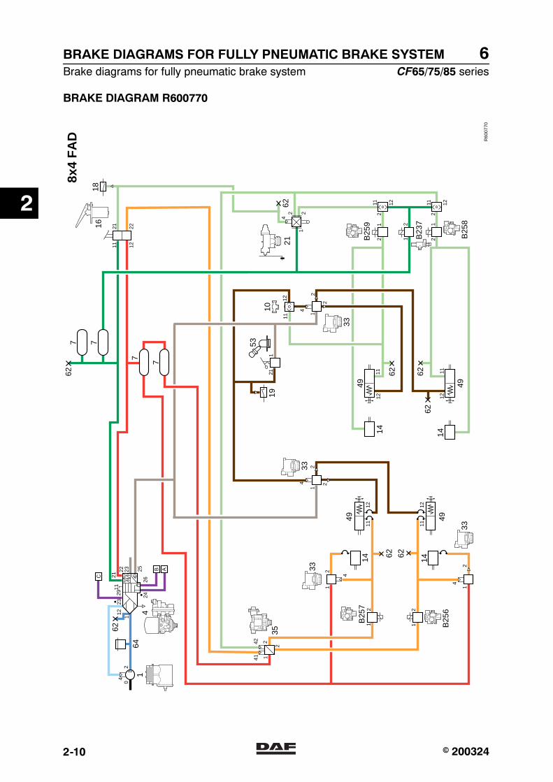
62 Emergency filler/test/tyre pump connection
64 Safety valve
B256 ABS valve, front axle, left
B257 ABS valve, front axle, right
B258 ABS valve, rear axle, left
B259 ABS valve, rear axle, right
B237 ASR valve
2
� 200324https://www.truck-manuals.net/
6BRAKE DIAGRAMS FOR FULLY PNEUMATIC BRAKE SYSTEM
Brake diagrams for fully pneumatic brake system CF65/75/85 series
2-2
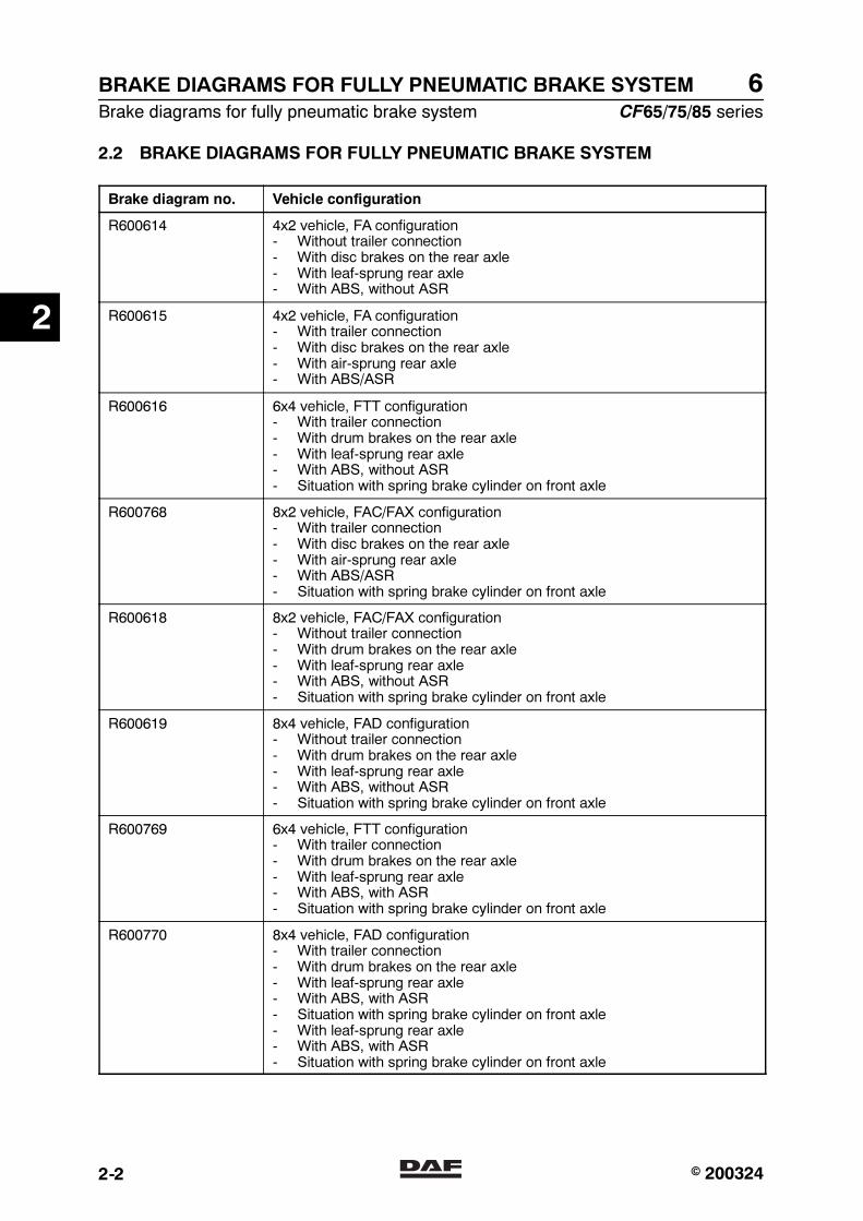
2.2 BRAKE DIAGRAMS FOR FULLY PNEUMATIC BRAKE SYSTEM
Brake diagram no. Vehicle configuration
R600614 4x2 vehicle, FA configuration- Without trailer connection- With disc brakes on the rear axle- With leaf-sprung rear axle- With ABS, without ASR
R600615 4x2 vehicle, FA configuration- With trailer connection- With disc brakes on the rear axle- With air-sprung rear axle- With ABS/ASR
R600616 6x4 vehicle, FTT configuration- With trailer connection- With drum brakes on the rear axle- With leaf-sprung rear axle- With ABS, without ASR- Situation with spring brake cylinder on front axle
R600768 8x2 vehicle, FAC/FAX configuration- With trailer connection- With disc brakes on the rear axle- With air-sprung rear axle- With ABS/ASR- Situation with spring brake cylinder on front axle
R600618 8x2 vehicle, FAC/FAX configuration- Without trailer connection- With drum brakes on the rear axle- With leaf-sprung rear axle- With ABS, without ASR- Situation with spring brake cylinder on front axle
R600619 8x4 vehicle, FAD configuration- Without trailer connection- With drum brakes on the rear axle- With leaf-sprung rear axle- With ABS, without ASR- Situation with spring brake cylinder on front axle
R600769 6x4 vehicle, FTT configuration- With trailer connection- With drum brakes on the rear axle- With leaf-sprung rear axle- With ABS, with ASR- Situation with spring brake cylinder on front axle
R600770 8x4 vehicle, FAD configuration- With trailer connection- With drum brakes on the rear axle- With leaf-sprung rear axle- With ABS, with ASR- Situation with spring brake cylinder on front axle- With leaf-sprung rear axle- With ABS, with ASR- Situation with spring brake cylinder on front axle
2
� 200324https://www.truck-manuals.net/
6
CF65/75/85 series Brake diagrams for fully pneumatic brake system
BRAKE DIAGRAMS FOR FULLY PNEUMATIC BRAKE SYSTEM
2-3
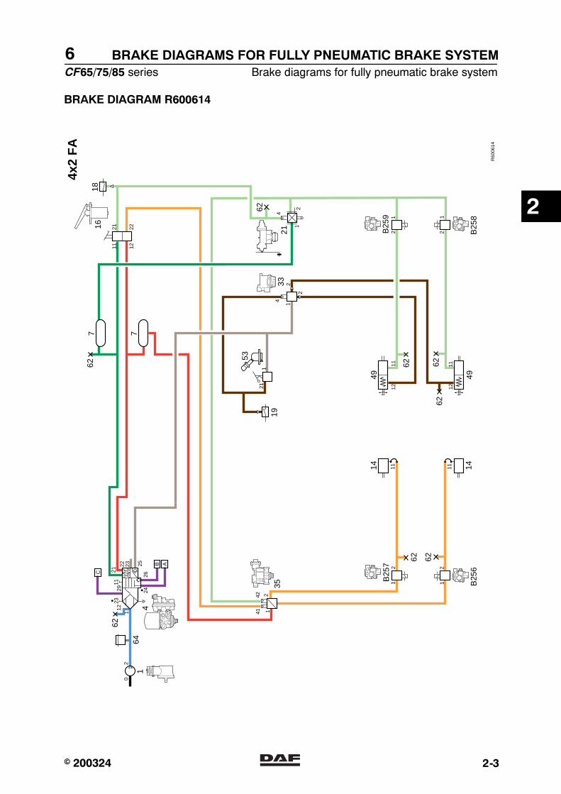
BRAKE DIAGRAM R600614
R60
0614
4x2
FA
62
14
3521
14
642
1112
11
4
2
2
1
1112
112
1
21
112
2311 12
21 22
2426
B
C
0
62 62
B25
7
uu
pp21
22 23 25 A
627 7
62 6262
49 49
19
1618
211
62
12
12
12
4
4
B25
9
B25
8B
256
1
53
33
2141
42
2911
2
� 200324https://www.truck-manuals.net/
6BRAKE DIAGRAMS FOR FULLY PNEUMATIC BRAKE SYSTEM
Brake diagrams for fully pneumatic brake system CF65/75/85 series
2-4
BRAKE DIAGRAM R600615
R60
0615
4x2
FA
62
14
3522
14
642
1112
11
4
2
2
1
1112
112
1
21
11223
11 12
21 22
2426
B
0
62 62
B25
7
uu
pp21
22 23 25 A
627 7
712
4612
62 6262
62
49 49
19
1618
21
4341
42
22
1
12
21112
1
2
4
1
2
21
4
B25
9
B25
8
11
B25
6
1
53
33
2141
42
12
22
B23
7
2911
C
2
� 200324https://www.truck-manuals.net/

6
CF65/75/85 series Brake diagrams for fully pneumatic brake system
BRAKE DIAGRAMS FOR FULLY PNEUMATIC BRAKE SYSTEM
2-5
BRAKE DIAGRAM R600616
R60
0616
6x4
FT
T
62
14 14
642
1211
4
2
21
4 2
2
1
1112
1112
1112
1112
21
21
112
2311 12
21 22
2426
B
04
62 62
4949
B25
7
uu
pp21
22 23 25 A
62
7 7
712
4612
7
62
6262
62
49 49
19
1618
21
4341
42
22
1
12
1
224
1
2
4
B25
9
B25
8B
256
1
53
3333
332
2
1
4
121122
2911
21
10
C
2
� 200324https://www.truck-manuals.net/
6BRAKE DIAGRAMS FOR FULLY PNEUMATIC BRAKE SYSTEM
Brake diagrams for fully pneumatic brake system CF65/75/85 series
2-6
BRAKE DIAGRAM R600768
R60
0768
8x2
FA
C
62
14
3522
642
1211
4
2
21
4 2
2
1
1112
1112
1112
21
21112
2311 12
21 22
2426
B
04
62 62
4949
B25
7
uu
pp21
22 23 25 A
62
7
712
4612
7
62 6262
62
49 49
19
1618
21
4341
42
22
1
224
1
4 B25
6
1
53
33
33
33
33
2
2
14142
121122
2911
2
2
12
11
12
24
21
2
1211
11 12
12 11
11 12
14
10
10
11B
259
B25
8
B23
7
21
4
7 7
21
4
33
33
1414
C
2
� 200324https://www.truck-manuals.net/
6
CF65/75/85 series Brake diagrams for fully pneumatic brake system
BRAKE DIAGRAMS FOR FULLY PNEUMATIC BRAKE SYSTEM
2-7
BRAKE DIAGRAM R600618
R60
0618
8x2
FA
C
62
14 14
35
642
1211
4
2
21
4 2
2
1
1112
1112
1112
1112
21
2
21
4
1
112
2311 12
21 22
2426
B
04
62 62
4949
B25
7
uu
pp21
22 23 25 A
62
77
7 7
62 6262
62
49 49
19
1618
21
4
211
12
1
224
1
2
4
B25
9
B25
8
B25
6
1
53
33
33
33
33
2
2
14142
2911
1414
21
C
2
� 200324https://www.truck-manuals.net/
6BRAKE DIAGRAMS FOR FULLY PNEUMATIC BRAKE SYSTEM
Brake diagrams for fully pneumatic brake system CF65/75/85 series
2-8
BRAKE DIAGRAM R600619
R60
0619
8x4
FA
D
62
14 14
35
642
1211
4
22
1
4 22
1
1112
1112
1112
1112
21
21
112
2311 12
21 22
2426
B
04
62 62
4949
B25
7
uu
pp21
22 23 25 A
62
77
62
6262
62
49 49
19
1618
211
12
1
224
1
2
4
B25
9
B25
8
B25
6
1
53
33
33
2
2
14142
2911
21
10
21
4
7 7
21
4
33
33
1414
C
2
� 200324https://www.truck-manuals.net/
6
CF65/75/85 series Brake diagrams for fully pneumatic brake system
BRAKE DIAGRAMS FOR FULLY PNEUMATIC BRAKE SYSTEM
2-9
BRAKE DIAGRAM R600769
R60
0769
6x4
FT
T
62
14 14
642
1211
4
2
21
4 2
2
1
1112
1112
1112
1112
21
21
112
2311 12
21 22
2426
B
04
62 62
4949
B25
7
uu
pp21
22 23 25 A
62
7 7
712
4612
7
62
6262
62
49 49
19
1618
21
4341
42
22
1
12
111 12
224
1
22
4
B25
6
1
53
3333
121122
2911
21
10
C
12
11 12
2
352
2
14142
B23
7
B25
9
B25
8
2
� 200324https://www.truck-manuals.net/
6BRAKE DIAGRAMS FOR FULLY PNEUMATIC BRAKE SYSTEM
Brake diagrams for fully pneumatic brake system CF65/75/85 series
2-10
BRAKE DIAGRAM R600770
R60
0770
8x4
FA
D
62
14 14
35
642
1211
4
22
1
4 22
1
1112
1112
1112
1112
21
21
112
2311 12
21 22
2426
B
04
62 62
4949
B25
7
uu
pp21
22 23 25 A
62
77
62
6262
62
49 49
19
1618
211
224
1
4
B25
6
1
53
33
33
2
2
14142
2911
21
10
21
4
7 7
21
4
33
33
1414
C
12
111 12
22
12
11 12
2
B25
9
B25
8
B23
7
2
� 200324https://www.truck-manuals.net/
© 200402 1
Contents
EBS BRAKE SYSTEM BRAKE DIAGRAMS
ΧΦ65/75/85 series
6
3
3 EBS brake system brake diagrams
CONTENTS
Page Date
1. GENERAL . . . . . . . . . . . . . . . . . . . . . . . . . . . . . . . . . . . . . . . . . . . . . . . . . . . . . . 1-1 . . . . . 200402
1.1 Brake diagrams . . . . . . . . . . . . . . . . . . . . . . . . . . . . . . . . . . . . . . . . . . . . . 1-1 . . . . . 200402
2. EBS BRAKE SYSTEM BRAKE DIAGRAMS . . . . . . . . . . . . . . . . . . . . . . . . . . . 2-1 . . . . . 200402
2.1 Legend, EBS brake system brake diagrams . . . . . . . . . . . . . . . . . . . . . . . 2-1 . . . . . 200402
2.2 EBS brake system brake diagrams . . . . . . . . . . . . . . . . . . . . . . . . . . . . . . 2-3 . . . . . 200402
3. EBS-2 BRAKE SYSTEM BRAKE DIAGRAMS . . . . . . . . . . . . . . . . . . . . . . . . . 3-1 . . . . . 200402
3.1 Legend, EBS brake system brake diagrams . . . . . . . . . . . . . . . . . . . . . . . 3-1 . . . . . 200402
3.2 EBS-2 brake system brake diagrams . . . . . . . . . . . . . . . . . . . . . . . . . . . . 3-3 . . . . . 200402
https://www.truck-manuals.net/

EBS BRAKE SYSTEM BRAKE DIAGRAMS
2 © 200402
Contents
3
ΧΦ65/75/85 series
6
https://www.truck-manuals.net/
© 200402 1-1
General
EBS BRAKE SYSTEM BRAKE DIAGRAMS
ΧΦ65/75/85 series
6
3
1. GENERAL
1.1 BRAKE DIAGRAMS
Due to the large number of variants for each vehicle type and for each country, it is impractical to list all these variants.
Thus a selection has been shown which can form the basis for other variants.
https://www.truck-manuals.net/

EBS BRAKE SYSTEM BRAKE DIAGRAMS
1-2 © 200402
General
3
ΧΦ65/75/85 series
6
https://www.truck-manuals.net/
© 200402 2-1
EBS brake system brake diagrams
EBS BRAKE SYSTEM BRAKE DIAGRAMS
ΧΦ65/75/85 series
6
3
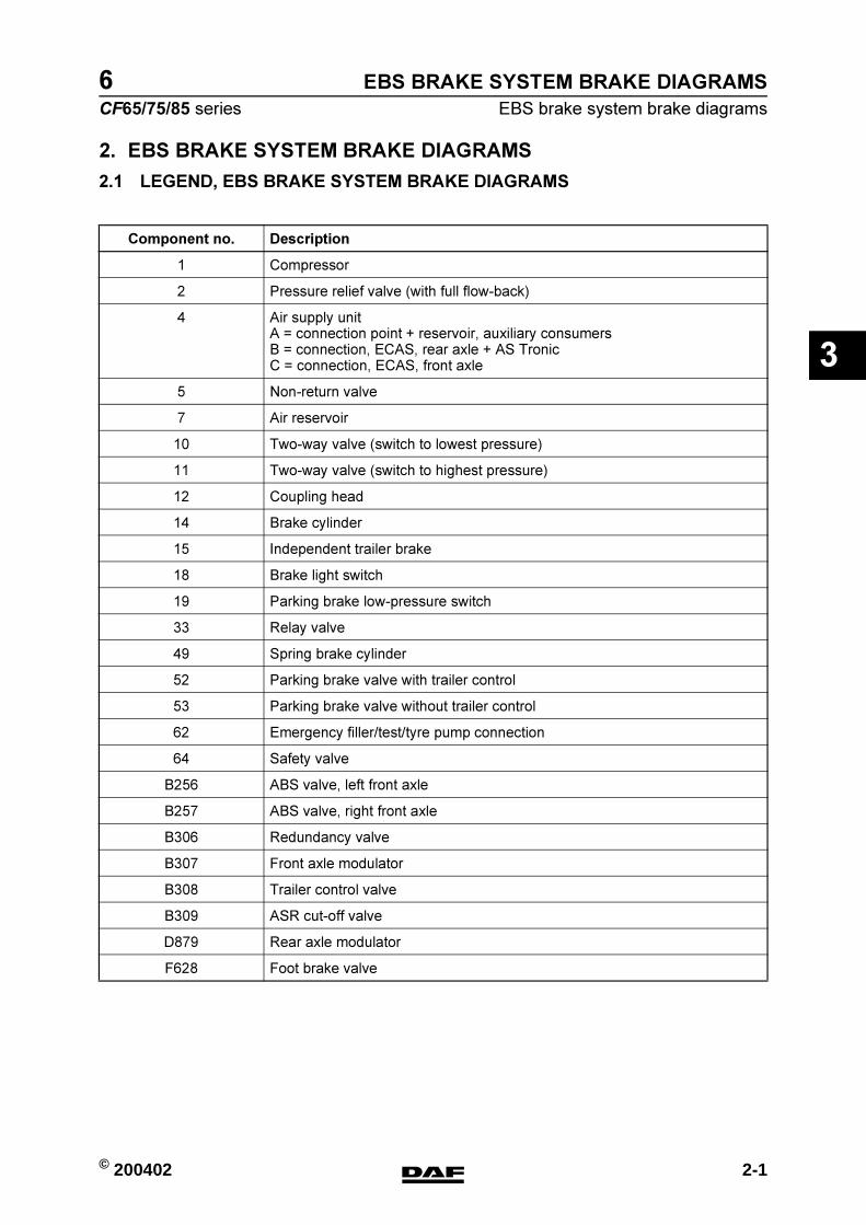
2. EBS BRAKE SYSTEM BRAKE DIAGRAMS
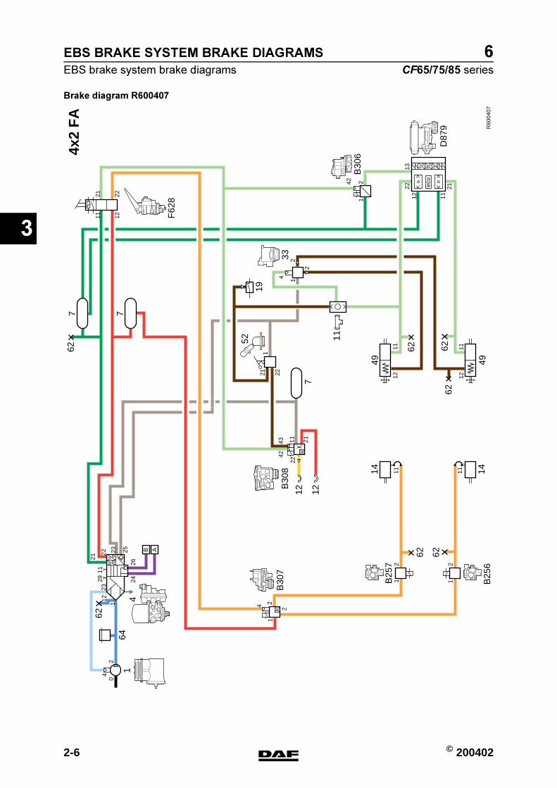
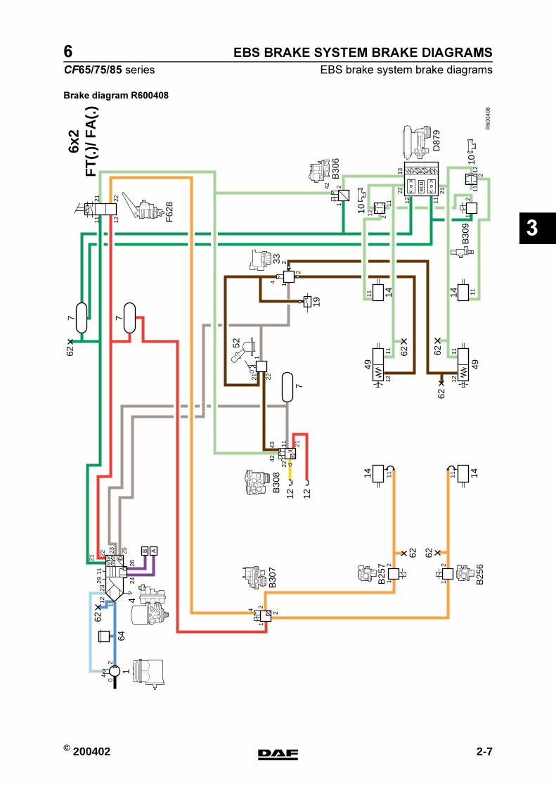
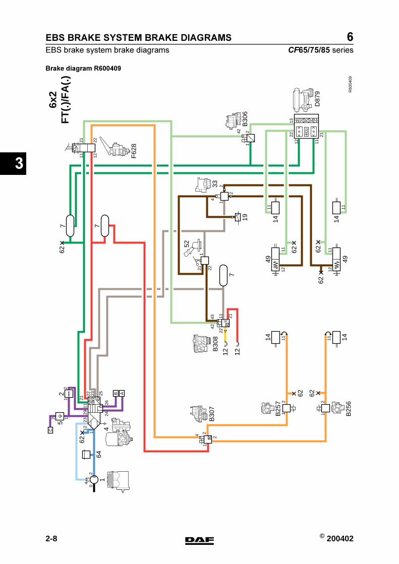
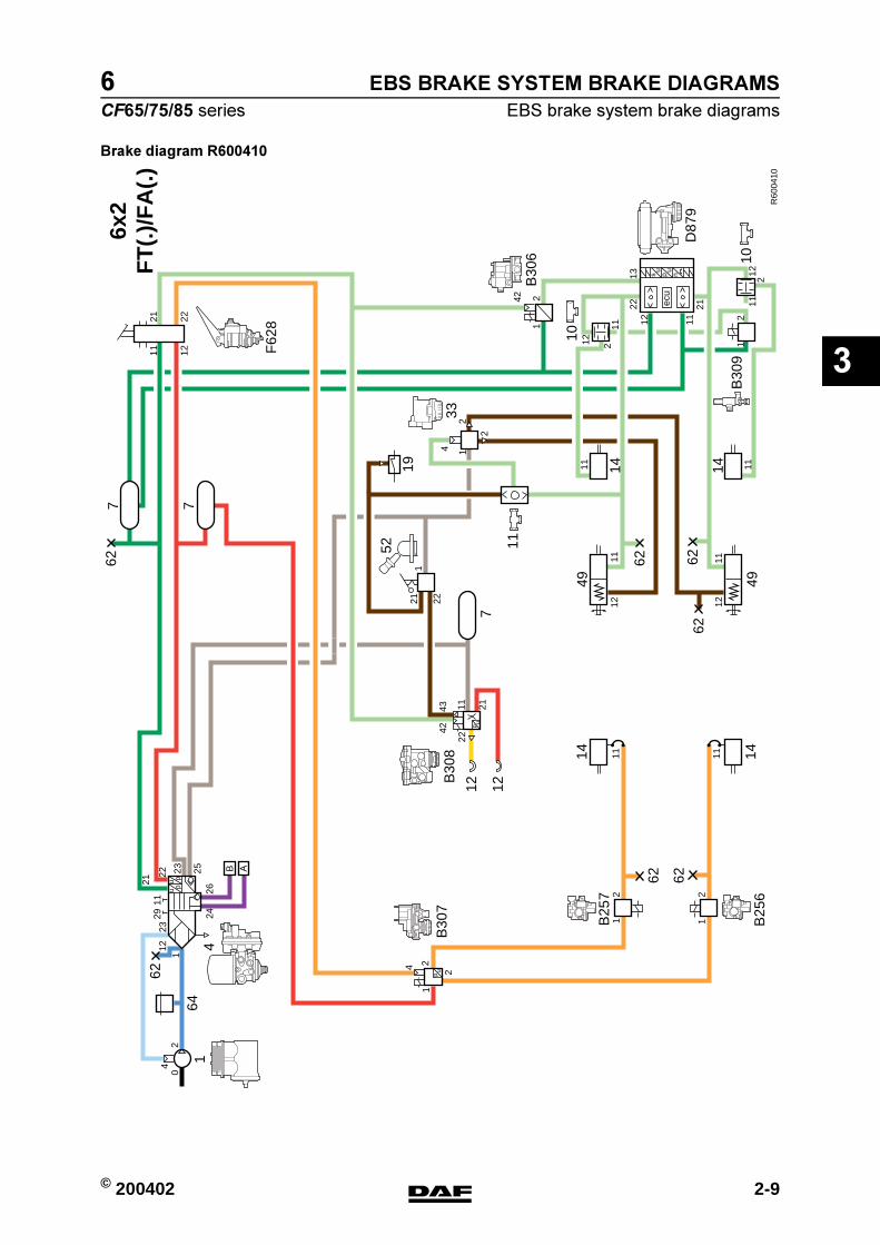
2.1 LEGEND, EBS BRAKE SYSTEM BRAKE DIAGRAMS
Component no. Description
1 Compressor
2 Pressure relief valve (with full flow-back)
4 Air supply unitA = connection point + reservoir, auxiliary consumersB = connection, ECAS, rear axle + AS TronicC = connection, ECAS, front axle
5 Non-return valve
7 Air reservoir
10 Two-way valve (switch to lowest pressure)
11 Two-way valve (switch to highest pressure)
12 Coupling head
14 Brake cylinder
15 Independent trailer brake
18 Brake light switch
19 Parking brake low-pressure switch
33 Relay valve
49 Spring brake cylinder
52 Parking brake valve with trailer control
53 Parking brake valve without trailer control
62 Emergency filler/test/tyre pump connection
64 Safety valve
B256 ABS valve, left front axle
B257 ABS valve, right front axle
B306 Redundancy valve
B307 Front axle modulator
B308 Trailer control valve
B309 ASR cut-off valve
D879 Rear axle modulator
F628 Foot brake valve
https://www.truck-manuals.net/
EBS BRAKE SYSTEM BRAKE DIAGRAMS
2-2 © 200402
EBS brake system brake diagrams
3
ΧΦ65/75/85 series
6
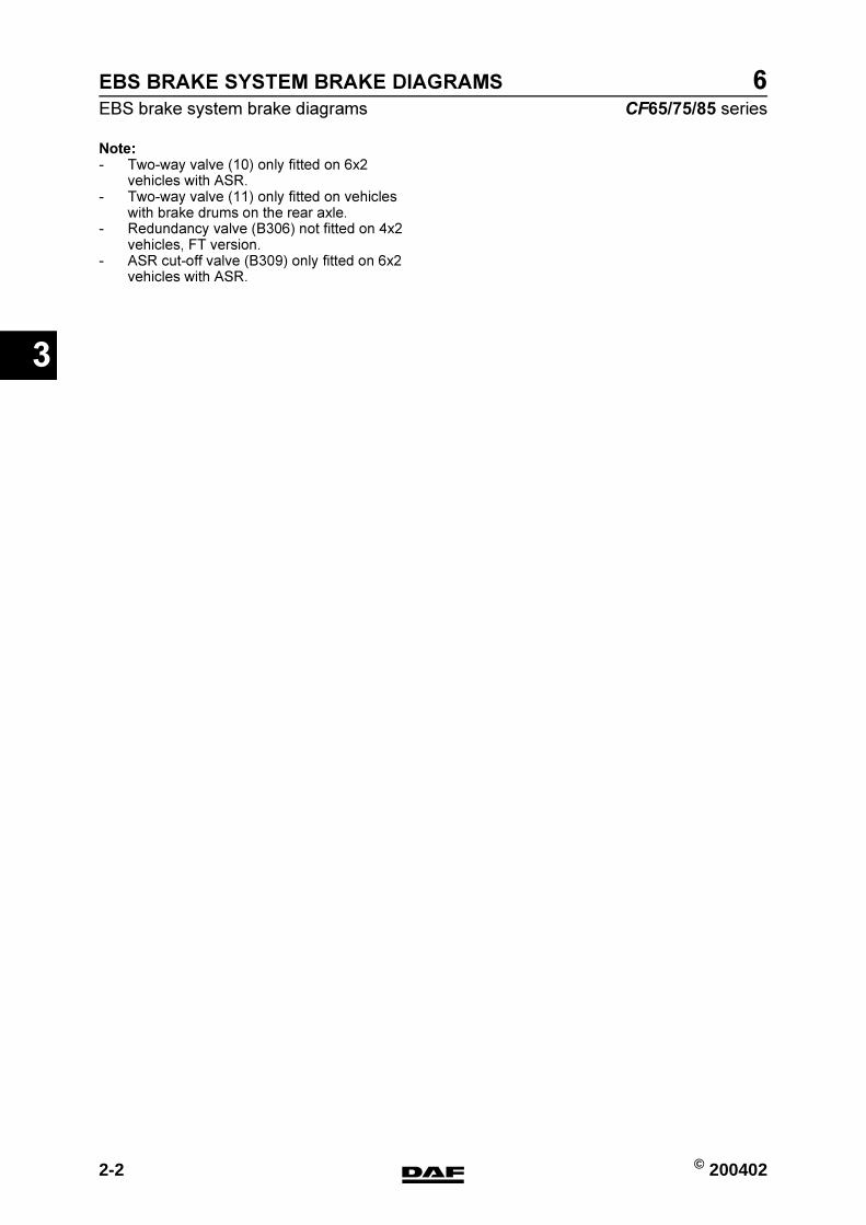
Note:- Two-way valve (10) only fitted on 6x2
vehicles with ASR.- Two-way valve (11) only fitted on vehicles
with brake drums on the rear axle.- Redundancy valve (B306) not fitted on 4x2
vehicles, FT version.- ASR cut-off valve (B309) only fitted on 6x2
vehicles with ASR.
https://www.truck-manuals.net/
© 200402 2-3
EBS brake system brake diagrams
EBS BRAKE SYSTEM BRAKE DIAGRAMS
ΧΦ65/75/85 series
6
3
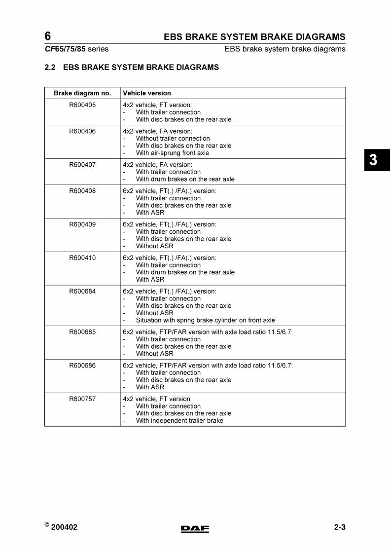
2.2 EBS BRAKE SYSTEM BRAKE DIAGRAMS
Brake diagram no. Vehicle version
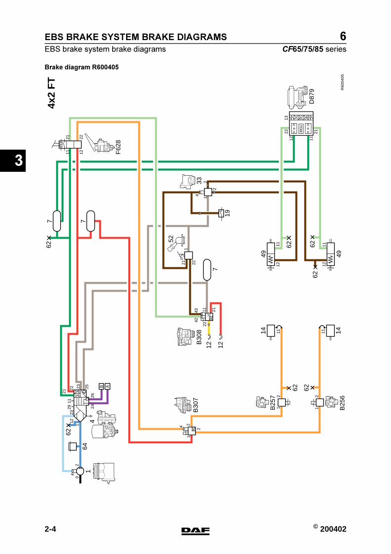
R600405 4x2 vehicle, FT version:- With trailer connection- With disc brakes on the rear axle
R600406 4x2 vehicle, FA version:- Without trailer connection- With disc brakes on the rear axle- With air-sprung front axle
R600407 4x2 vehicle, FA version:- With trailer connection- With drum brakes on the rear axle
R600408 6x2 vehicle, FT(.) /FA(.) version:- With trailer connection- With disc brakes on the rear axle- With ASR
R600409 6x2 vehicle, FT(.) /FA(.) version:- With trailer connection- With disc brakes on the rear axle- Without ASR
R600410 6x2 vehicle, FT(.) /FA(.) version:- With trailer connection- With drum brakes on the rear axle- With ASR
R600684 6x2 vehicle, FT(.) /FA(.) version:- With trailer connection- With disc brakes on the rear axle- Without ASR- Situation with spring brake cylinder on front axle
R600685 6x2 vehicle, FTP/FAR version with axle load ratio 11.5/6.7:- With trailer connection- With disc brakes on the rear axle- Without ASR
R600686 6x2 vehicle, FTP/FAR version with axle load ratio 11.5/6.7:- With trailer connection- With disc brakes on the rear axle- With ASR
R600757 4x2 vehicle, FT version- With trailer connection- With disc brakes on the rear axle- With independent trailer brake
https://www.truck-manuals.net/
EBS BRAKE SYSTEM BRAKE DIAGRAMS
2-4 © 200402
EBS brake system brake diagrams
3
ΧΦ65/75/85 series
6
Brake diagram R600405
R60
0405
4x2
FT
F62
8
B30
7
14
B25
7
B25
6
B30
8
D87
9
52
3311
7
62
14 14
19
642
1112
11
2
2
443
42
21
221
21
1322
1112
1112
11
21
2
4 2
2
1
1
112
2329
11 12
21 22
2426
B
04
62 62
uu
pp
1121
22 23 25 A
627 7
62 6262
up
49 49
12u
p
12
211
22
ecu
su u
p n
https://www.truck-manuals.net/

© 200402 2-5
EBS brake system brake diagrams
EBS BRAKE SYSTEM BRAKE DIAGRAMS
ΧΦ65/75/85 series
6
3
Brake diagram R600406
R60
0406
4x2
FA
62
14 14
19
642
1112
11
4
2
2
1
21
1322
1112
1112
11
21
2
4 2
2
1
1
112
2329
11 12
21 22
2426
B
04
62 62
B25
7
uu
pp
1121
22 23 25 A
627 7
62 6262
up
49 49
211
242
1
ecu
su u
p n
F62
8
B30
6
B30
7
4
B25
7
B25
6
1
D87
9
53
33
52
12
12
C
https://www.truck-manuals.net/
EBS BRAKE SYSTEM BRAKE DIAGRAMS
2-6 © 200402
EBS brake system brake diagrams
3
ΧΦ65/75/85 series
6
Brake diagram R600407
R60
0407
4x2
FA
11
7
F62
8
62
14 14
19
B30
6
B30
7
164
4
2
1112
11
4
2
2
4342
21
221
21
1322
1112
1112
11
21
2
4 2
2
1
1
112
2329
11 12
21 22
2426
B
04
62 62
B25
7
B25
6uu
pp
1121
22 23 25 A
627 7
62 6262
up
49 49
12u
p
12
B30
8
211
22
242
1
ecu
su u
p n
D87
9
52
33
11
https://www.truck-manuals.net/
© 200402 2-7
EBS brake system brake diagrams
EBS BRAKE SYSTEM BRAKE DIAGRAMS
ΧΦ65/75/85 series
6
3
Brake diagram R600408
R60
0408
6x2
FT
(.)/
FA
(.)
F62
8
B30
6
B30
7
14
B25
7
B25
6
B30
8
D87
9
52
3311
7
62
14 14
19
642
1112
11
4
11
2
2
4342
21
221
1111
11
12
12
2
21
1322
1112
2
2 1
1112
11
21
2
4 2
2
1
1
11223
2911 12
21 22
2426
B
04
62 62
uu
pp
1121
22 23 25 A
627 7
62 6262
up
49
14 14
49
12u
p
12
211
22
242
1
ecu
su u
p n
B30
910
10
https://www.truck-manuals.net/
EBS BRAKE SYSTEM BRAKE DIAGRAMS
2-8 © 200402
EBS brake system brake diagrams
3
ΧΦ65/75/85 series
6
Brake diagram R600409
R60
0409
11
6x2
FT
(.)/
FA
(.)
11
7
62
14 14
19
642
1112
11
4
2
2
4342
21
221
11
21
1322
1112
1112
112
1
2
4 2
2
1
1
1
1223
11 12
21 22
2426
B
04
62 62
uu
pp21
22 23 25 A
627 7
62 6262
up
4914 14
49
12u
p
12
211
22
242
1
ecu
su u
p n
2911
F62
8
B30
6
B30
7
14
B25
7
B25
6
B30
8
D87
9
52
33
52
12
12
C
https://www.truck-manuals.net/
© 200402 2-9
EBS brake system brake diagrams
EBS BRAKE SYSTEM BRAKE DIAGRAMS
ΧΦ65/75/85 series
6
3
Brake diagram R600410
R60
0410
11
6x2
FT
(.)/
FA
(.)
19
11
3311
7
62
14 14
642
1112
11
4
2
2
4342
21
221
1111
11
12
12
2
21
1322
1112
2
2 1
1112
11
21
2
4 2
2
1
1
112
2329
11 12
21 22
2426
B
04
62 62
uu
pp
1121
22 23 25 A
627 7
62 6262
up
49
14 14
49
12u
p
12
211
22
242
1
ecu
su u
p n
F62
8
B30
6
B30
7
14
B25
7
B25
6
B30
8
D87
9
52
B30
910
10
https://www.truck-manuals.net/

EBS BRAKE SYSTEM BRAKE DIAGRAMS
2-10 © 200402
EBS brake system brake diagrams
3
ΧΦ65/75/85 series
6
Brake diagram R600684
R60
0684
11
6x2
FT
(.)/
FA
(.)
11
7
62
19
642
1112
11
4
2
2
4342
21
221
11
21
1322
1112
1112
21
2
4 2
2
1
1
1
1211 12
21 22
2426
B
04
62 62
uu
pp21
22 23 25 A
627 7
62 6262
up
4914 14
49
12u
p
12
211
22
242
1
ecu
su u
p n
F62
8
B30
6
B30
7
14
B25
7
B25
6
B30
8
D87
9
52
33
11
12 12
49 49
2
33
2329
11
4
2
1
https://www.truck-manuals.net/

© 200402 2-11
EBS brake system brake diagrams
EBS BRAKE SYSTEM BRAKE DIAGRAMS
ΧΦ65/75/85 series
6
3
Brake diagram R600685
R60
0685
11
6x2
FT
P/F
AR
11,5
/6,7
11
7
62
14 14
19
642
1112
11
4
2
2
4342
21
221
1112
11
21
2
4 2
2
1
1
1
1223
11 12
21 22
2426
B
04
62 62uu
pp21
22 23 25 A
627 7
62
up
4914
49
12u
p
12
211
22
F62
8
B30
7
14
B25
7
B25
6
B30
8
52
33
11
21
1322
1112
62 62
14
242
1
ecu
su u
p n
B30
6
D87
9
1 24
33
33
2e
1
4
2
2911
https://www.truck-manuals.net/
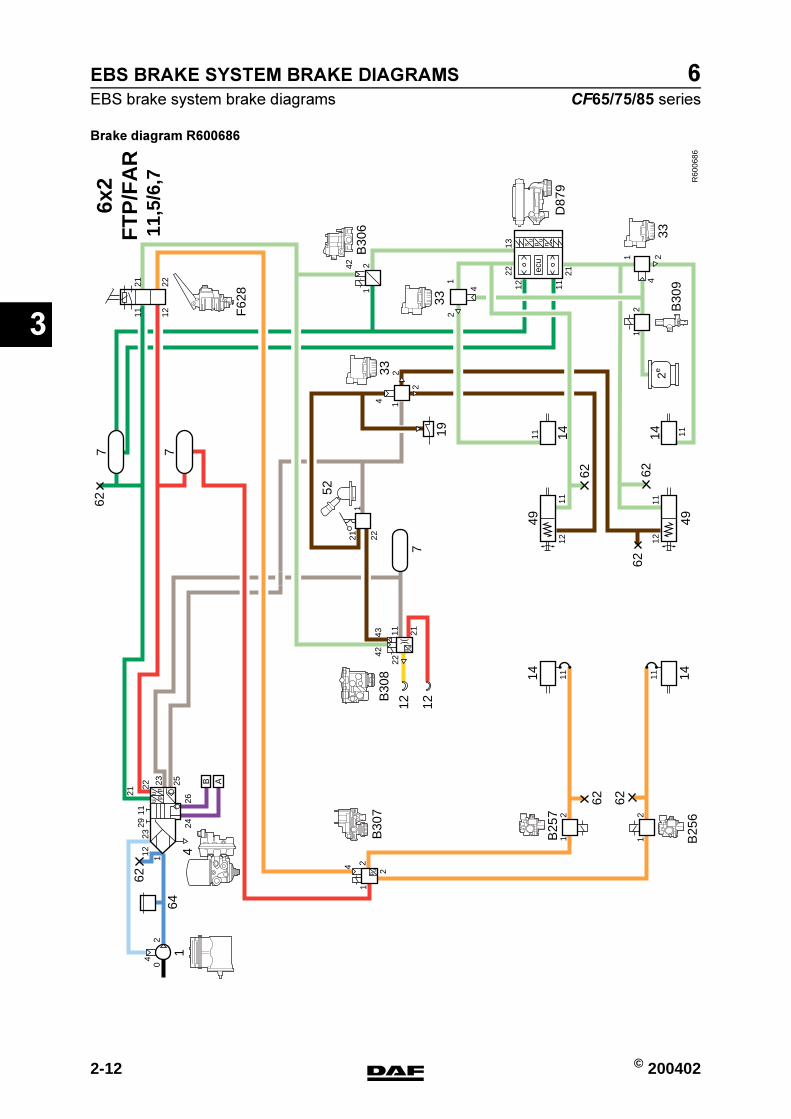
EBS BRAKE SYSTEM BRAKE DIAGRAMS
2-12 © 200402
EBS brake system brake diagrams
3
ΧΦ65/75/85 series
6
Brake diagram R600686
R60
0686
F62
8
B30
7
14
B25
7
B25
6
B30
8
52
3311
7
62
14 14
19
642
1112
11
4
2
2
4342
21
221
1112
11
21
2
4 2
2
1
1
11223
2911 12
21 22
2426
B
04
62 62uu
pp
1121
22 23 25 A
627 7
62
up
49 49
12u
p
12
211
22
11 11
21
14 14
B30
9
21
1322
1112
242
1
ecu
su u
p n
B30
6
D87
9
1
4
2
1 24
33
33
2e
62 62
6x2
FT
P/F
AR
11,5
/6,7
https://www.truck-manuals.net/
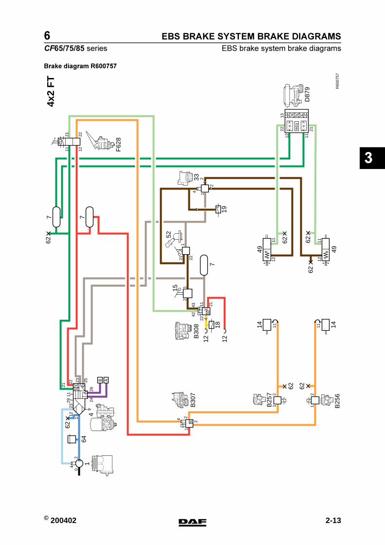
© 200402 2-13
EBS brake system brake diagrams
EBS BRAKE SYSTEM BRAKE DIAGRAMS
ΧΦ65/75/85 series
6
3
Brake diagram R600757
R60
0757
4x2
FT
F62
8
B30
7
14
B25
7
B25
6
B30
8
D87
9
52
3311
21
7
62
14 14
19
642
1112
11
2
2
443
42
21
221
21
1322
1112
1112
11
21
2
4 2
2
1
1
112
2329
11 12
21 22
2426
B
04
62 62uu
pp
1121
22 23 25 A
627 7
62 6262
up
49 49
12u
p
12
211
22
ecu
su u
p n
18
15
https://www.truck-manuals.net/
EBS BRAKE SYSTEM BRAKE DIAGRAMS
2-14 © 200402
EBS brake system brake diagrams
3
ΧΦ65/75/85 series
6
https://www.truck-manuals.net/

© 200402 3-1
EBS-2 brake system brake diagrams
EBS BRAKE SYSTEM BRAKE DIAGRAMS
ΧΦ65/75/85 series
6
3
3. EBS-2 BRAKE SYSTEM BRAKE DIAGRAMS
3.1 LEGEND, EBS BRAKE SYSTEM BRAKE DIAGRAMS
Component no. Description
1 Compressor
2 Pressure relief valve (with full flow-back)
4 Air supply unitA = connection point + reservoir, auxiliary consumersB = connection, ECAS, rear axle + AS TronicC = connection, ECAS, front axle
5 Non-return valve
7 Air reservoir
10 Two-way valve (switch to lowest pressure)
11 Two-way valve (switch to highest pressure)
12 Coupling head
14 Brake cylinder
15 Independent trailer brake
18 Brake light switch
19 Parking brake low-pressure switch
33 Relay valve
49 Spring brake cylinder
52 Parking brake valve with trailer control
53 Parking brake valve without trailer control
62 Emergency filler/test/tyre pump connection
64 Safety valve
B256 ABS valve, left front axle
B257 ABS valve, right front axle
B306 Redundancy valve
B307 Front axle modulator
B308 Trailer control valve
B309 ASR cut-off valve
D978 Rear axle modulator
F628 Foot brake valve
https://www.truck-manuals.net/

EBS BRAKE SYSTEM BRAKE DIAGRAMS
3-2 © 200402
EBS-2 brake system brake diagrams
3
ΧΦ65/75/85 series
6
Note:- Two-way valve (10) only fitted on 6x2
vehicles with ASR.- Two-way valve (11) only fitted on vehicles
with brake drums on the rear axle.- Redundancy valve (B306) not fitted on 4x2
vehicles, FT version.- ASR cut-off valve (B309) only fitted on 6x2
vehicles with ASR.
https://www.truck-manuals.net/

© 200402 3-3
EBS-2 brake system brake diagrams
EBS BRAKE SYSTEM BRAKE DIAGRAMS
ΧΦ65/75/85 series
6
3
3.2 EBS-2 BRAKE SYSTEM BRAKE DIAGRAMS
Brake diagram no. Vehicle version
R600834 4x2 vehicle, FT version:- With trailer connection- With disc brakes on the rear axle
R600835 4x2 vehicle, FA version:- Without trailer connection- With disc brakes on the rear axle- With air-sprung front axle
R600836 4x2 vehicle, FA version:- With trailer connection- With drum brakes on the rear axle
R600837 6x2 vehicle, FT(.) /FA(.) version:- With trailer connection- With disc brakes on the rear axle- With ASR
R600838 6x2 vehicle, FT(.) /FA(.) version:- With trailer connection- With disc brakes on the rear axle- Without ASR
R600839 6x2 vehicle, FT(.) /FA(.) version:- With trailer connection- With drum brakes on the rear axle- With ASR
R600840 6x2 vehicle, FT(.) /FA(.) version:- With trailer connection- With disc brakes on the rear axle- Without ASR- Situation with spring brake cylinder on front axle
R600841 6x2 vehicle, FTP/FAR version with axle load ratio 11.5/6.7:- With trailer connection- With disc brakes on the rear axle- Without ASR
R600842 6x2 vehicle, FTP/FAR version with axle load ratio 11.5/6.7:- With trailer connection- With disc brakes on the rear axle- With ASR
R600843 4x2 vehicle, FT version- With trailer connection- With disc brakes on the rear axle- With independent trailer brake
https://www.truck-manuals.net/

EBS BRAKE SYSTEM BRAKE DIAGRAMS
3-4 © 200402
EBS-2 brake system brake diagrams
3
ΧΦ65/75/85 series
6
Brake diagram R600834
R60
0405
4x2
FT
F62
8
B30
7
14
B25
7
B25
6
B30
8
D87
9
52
3311
7
62
14 14
19
642
1112
11
2
2
443
42
21
221
21
1322
1112
1112
11
21
2
4 2
2
1
1
112
2329
11 12
21 22
2426
B
04
62 62
uu
pp
1121
22 23 25 A
627 7
62 6262
up
49 49
12u
p
12
211
22
ecu
su u
p n
https://www.truck-manuals.net/
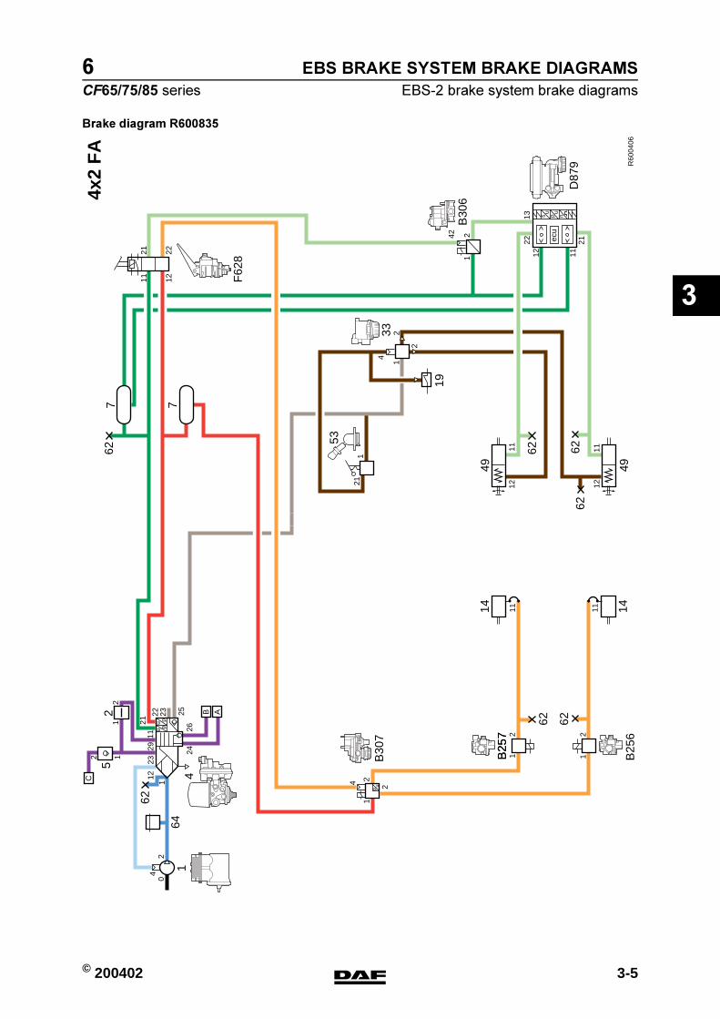
© 200402 3-5
EBS-2 brake system brake diagrams
EBS BRAKE SYSTEM BRAKE DIAGRAMS
ΧΦ65/75/85 series
6
3
Brake diagram R600835
R60
0406
4x2
FA
62
14 14
19
642
1112
11
4
2
2
1
21
1322
1112
1112
11
21
2
4 2
2
1
1
112
2329
11 12
21 22
2426
B
04
62 62
B25
7
uu
pp
1121
22 23 25 A
627 7
62 6262
up
49 49
211
242
1
ecu
su u
p n
F62
8
B30
6
B30
7
4
B25
7
B25
6
1
D87
9
53
33
52
12
12
C
https://www.truck-manuals.net/

EBS BRAKE SYSTEM BRAKE DIAGRAMS
3-6 © 200402
EBS-2 brake system brake diagrams
3
ΧΦ65/75/85 series
6
Brake diagram R600836
R60
0407
4x2
FA
11
7
F62
8
62
14 14
19
B30
6
B30
7
164
4
2
1112
11
4
2
2
4342
21
221
21
1322
1112
1112
11
21
2
4 2
2
1
1
112
2329
11 12
21 22
2426
B
04
62 62
B25
7
B25
6uu
pp
1121
22 23 25 A
627 7
62 6262
up
49 49
12u
p
12
B30
8
211
22
242
1
ecu
su u
p n
D87
9
52
33
11
https://www.truck-manuals.net/

© 200402 3-7
EBS-2 brake system brake diagrams
EBS BRAKE SYSTEM BRAKE DIAGRAMS
ΧΦ65/75/85 series
6
3
Brake diagram R600837
R60
0408
6x2
FT
(.)/
FA
(.)
F62
8
B30
6
B30
7
14
B25
7
B25
6
B30
8
D87
9
52
3311
7
62
14 14
19
642
1112
11
4
11
2
2
4342
21
221
1111
11
12
12
2
21
1322
1112
2
2 1
1112
11
21
2
4 2
2
1
1
11223
2911 12
21 22
2426
B
04
62 62
uu
pp
1121
22 23 25 A
627 7
62 6262
up
49
14 14
49
12u
p
12
211
22
242
1
ecu
su u
p n
B30
910
10
https://www.truck-manuals.net/
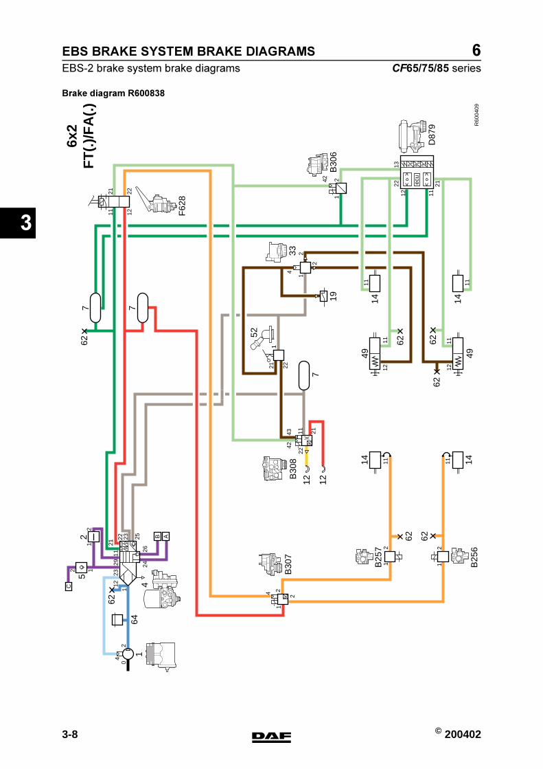
EBS BRAKE SYSTEM BRAKE DIAGRAMS
3-8 © 200402
EBS-2 brake system brake diagrams
3
ΧΦ65/75/85 series
6
Brake diagram R600838
R60
0409
11
6x2
FT
(.)/
FA
(.)
11
7
62
14 14
19
642
1112
11
4
2
2
4342
21
221
11
21
1322
1112
1112
112
1
2
4 2
2
1
1
1
1223
11 12
21 22
2426
B
04
62 62
uu
pp21
22 23 25 A
627 7
62 6262
up
4914 14
49
12u
p
12
211
22
242
1
ecu
su u
p n
2911
F62
8
B30
6
B30
7
14
B25
7
B25
6
B30
8
D87
9
52
33
52
12
12
C
https://www.truck-manuals.net/

© 200402 3-9
EBS-2 brake system brake diagrams
EBS BRAKE SYSTEM BRAKE DIAGRAMS
ΧΦ65/75/85 series
6
3
Brake diagram R600839
R60
0410
11
6x2
FT
(.)/
FA
(.)
19
11
3311
7
62
14 14
642
1112
11
4
2
2
4342
21
221
1111
11
12
12
2
21
1322
1112
2
2 1
1112
11
21
2
4 2
2
1
1
112
2329
11 12
21 22
2426
B
04
62 62
uu
pp
1121
22 23 25 A
627 7
62 6262
up
49
14 14
49
12u
p
12
211
22
242
1
ecu
su u
p n
F62
8
B30
6
B30
7
14
B25
7
B25
6
B30
8
D87
9
52
B30
910
10
https://www.truck-manuals.net/
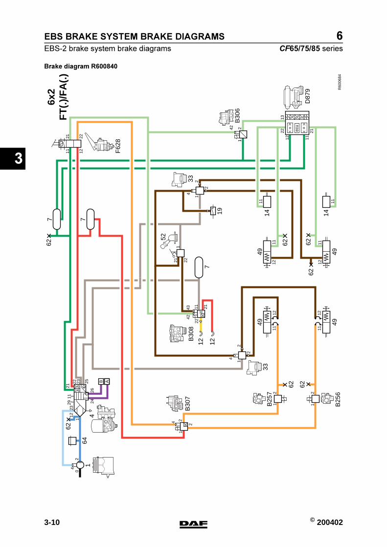
EBS BRAKE SYSTEM BRAKE DIAGRAMS
3-10 © 200402
EBS-2 brake system brake diagrams
3
ΧΦ65/75/85 series
6
Brake diagram R600840
R60
0684
11
6x2
FT
(.)/
FA
(.)
11
7
62
19
642
1112
11
4
2
2
4342
21
221
11
21
1322
1112
1112
21
2
4 2
2
1
1
1
1211 12
21 22
2426
B
04
62 62
uu
pp21
22 23 25 A
627 7
62 6262
up
4914 14
49
12u
p
12
211
22
242
1
ecu
su u
p n
F62
8
B30
6
B30
7
14
B25
7
B25
6
B30
8
D87
9
52
33
11
12 12
49 49
2
33
2329
11
4
2
1
https://www.truck-manuals.net/
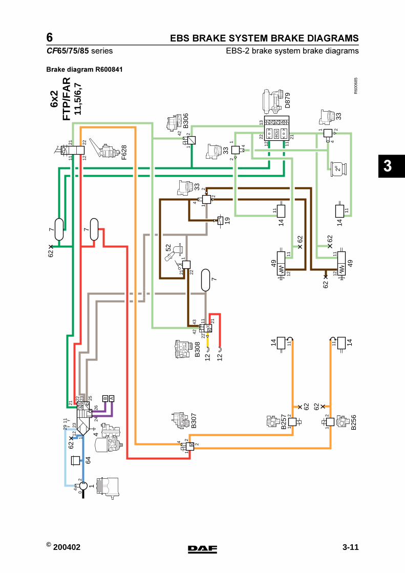
© 200402 3-11
EBS-2 brake system brake diagrams
EBS BRAKE SYSTEM BRAKE DIAGRAMS
ΧΦ65/75/85 series
6
3
Brake diagram R600841
R60
0685
11
6x2
FT
P/F
AR
11,5
/6,7
11
7
62
14 14
19
642
1112
11
4
2
2
4342
21
221
1112
11
21
2
4 2
2
1
1
1
1223
11 12
21 22
2426
B
04
62 62uu
pp21
22 23 25 A
627 7
62
up
4914
49
12u
p
12
211
22
F62
8
B30
7
14
B25
7
B25
6
B30
8
52
33
11
21
1322
1112
62 62
14
242
1
ecu
su u
p n
B30
6
D87
9
1 24
33
33
2e
1
4
2
2911
https://www.truck-manuals.net/

EBS BRAKE SYSTEM BRAKE DIAGRAMS
3-12 © 200402
EBS-2 brake system brake diagrams
3
ΧΦ65/75/85 series
6
Brake diagram R600842
R60
0686
F62
8
B30
7
14
B25
7
B25
6
B30
8
52
3311
7
62
14 14
19
642
1112
11
4
2
2
4342
21
221
1112
11
21
2
4 2
2
1
1
11223
2911 12
21 22
2426
B
04
62 62uu
pp
1121
22 23 25 A
627 7
62
up
49 49
12u
p
12
211
22
11 11
21
14 14
B30
9
21
1322
1112
242
1
ecu
su u
p n
B30
6
D87
9
1
4
2
1 24
33
33
2e
62 62
6x2
FT
P/F
AR
11,5
/6,7
https://www.truck-manuals.net/

© 200402 3-13
EBS-2 brake system brake diagrams
EBS BRAKE SYSTEM BRAKE DIAGRAMS
ΧΦ65/75/85 series
6
3
Brake diagram R600843
R60
0757
4x2
FT
F62
8
B30
7
14
B25
7
B25
6
B30
8
D87
9
52
3311
21
7
62
14 14
19
642
1112
11
2
2
443
42
21
221
21
1322
1112
1112
11
21
2
4 2
2
1
1
112
2329
11 12
21 22
2426
B
04
62 62uu
pp
1121
22 23 25 A
627 7
62 6262
up
49 49
12u
p
12
211
22
ecu
su u
p n
18
15
https://www.truck-manuals.net/
EBS BRAKE SYSTEM BRAKE DIAGRAMS
3-14 © 200402
EBS-2 brake system brake diagrams
3
ΧΦ65/75/85 series
6
https://www.truck-manuals.net/
6
CF65/75/85 series Contents
OPERATION OF BRAKE COMPONENTS
1
CONTENTS
Page Date
1. GENERAL 1-1 200324. . . . . . . . . . . . . . . . . . . . . . . . . . . . . . . . . . . . . . . . . . . . . . . . . . . . . . . . . . . . . . . .1.1 Overview drawing, Knorr SB7000 disc brake construction 1-2 200324. . . . . . . . . . . . . . . . . .1.2 Overview drawing, Knorr SN7000 disc brake construction 1-4 200324. . . . . . . . . . . . . . . . . .
2. DESCRIPTION OF COMPONENTS 2-1 200324. . . . . . . . . . . . . . . . . . . . . . . . . . . . . . . . . . . . . . . . . .2.1 Compressor 2-1 200324. . . . . . . . . . . . . . . . . . . . . . . . . . . . . . . . . . . . . . . . . . . . . . . . . . . . . . . . . .2.2 Safety valve 2-2 200324. . . . . . . . . . . . . . . . . . . . . . . . . . . . . . . . . . . . . . . . . . . . . . . . . . . . . . . . . .2.3 Air supply unit 2-3 200324. . . . . . . . . . . . . . . . . . . . . . . . . . . . . . . . . . . . . . . . . . . . . . . . . . . . . . . .2.4 Water blow-off valve 2-8 200324. . . . . . . . . . . . . . . . . . . . . . . . . . . . . . . . . . . . . . . . . . . . . . . . . . .2.5 Foot brake valve 2-9 200324. . . . . . . . . . . . . . . . . . . . . . . . . . . . . . . . . . . . . . . . . . . . . . . . . . . . . .2.6 Relay valve 2-11 200324. . . . . . . . . . . . . . . . . . . . . . . . . . . . . . . . . . . . . . . . . . . . . . . . . . . . . . . . .2.7 Empty/load relay valve 2-12 200324. . . . . . . . . . . . . . . . . . . . . . . . . . . . . . . . . . . . . . . . . . . . . . .2.8 Brake light switch 2-14 200324. . . . . . . . . . . . . . . . . . . . . . . . . . . . . . . . . . . . . . . . . . . . . . . . . . . .2.9 Load sensing valve, air suspension 2-15 200324. . . . . . . . . . . . . . . . . . . . . . . . . . . . . . . . . . . . .2.10 Load sensing valve, leaf suspension 2-19 200324. . . . . . . . . . . . . . . . . . . . . . . . . . . . . . . . . . . .2.11 ABS valve 2-23 200324. . . . . . . . . . . . . . . . . . . . . . . . . . . . . . . . . . . . . . . . . . . . . . . . . . . . . . . . . .2.12 Two-way valve 2-25 200324. . . . . . . . . . . . . . . . . . . . . . . . . . . . . . . . . . . . . . . . . . . . . . . . . . . . . .2.13 ASR solenoid valve 2-26 200324. . . . . . . . . . . . . . . . . . . . . . . . . . . . . . . . . . . . . . . . . . . . . . . . . .2.14 Emergency filling/test connection 2-27 200324. . . . . . . . . . . . . . . . . . . . . . . . . . . . . . . . . . . . . .2.15 Brake cylinder 2-28 200324. . . . . . . . . . . . . . . . . . . . . . . . . . . . . . . . . . . . . . . . . . . . . . . . . . . . . . .2.16 Parking brake valve 2-29 200324. . . . . . . . . . . . . . . . . . . . . . . . . . . . . . . . . . . . . . . . . . . . . . . . . .2.17 Low-pressure switch 2-33 200324. . . . . . . . . . . . . . . . . . . . . . . . . . . . . . . . . . . . . . . . . . . . . . . . .2.18 Spring brake cylinder 2-34 200324. . . . . . . . . . . . . . . . . . . . . . . . . . . . . . . . . . . . . . . . . . . . . . . . .2.19 Trailer vehicle control valve 2-37 200324. . . . . . . . . . . . . . . . . . . . . . . . . . . . . . . . . . . . . . . . . . .2.20 Coupling head 2-41 200324. . . . . . . . . . . . . . . . . . . . . . . . . . . . . . . . . . . . . . . . . . . . . . . . . . . . . . .2.21 Automatic brake adjuster 2-42 200324. . . . . . . . . . . . . . . . . . . . . . . . . . . . . . . . . . . . . . . . . . . . .2.22 Disc brake 2-44 200324. . . . . . . . . . . . . . . . . . . . . . . . . . . . . . . . . . . . . . . . . . . . . . . . . . . . . . . . . .2.23 Quick-release coupling 2-46 200324. . . . . . . . . . . . . . . . . . . . . . . . . . . . . . . . . . . . . . . . . . . . . . .
4
� 200324https://www.truck-manuals.net/
6OPERATION OF BRAKE COMPONENTS
Contents CF65/75/85 series
2
4
� 200324https://www.truck-manuals.net/

6
CF65/75/85 series General
OPERATION OF BRAKE COMPONENTS
1-1
1. GENERAL
4
� 200324https://www.truck-manuals.net/
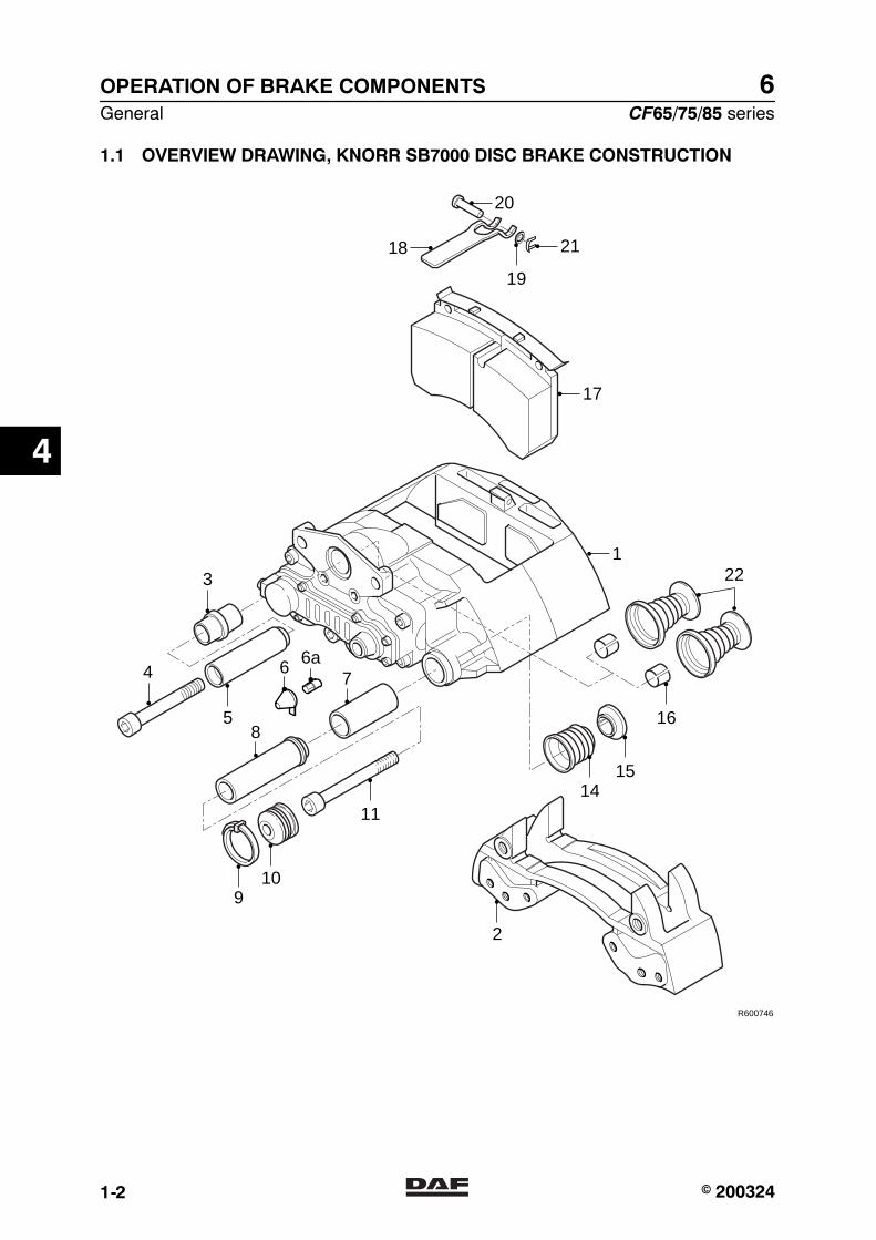
6OPERATION OF BRAKE COMPONENTS
General CF65/75/85 series
1-2
1.1 OVERVIEW DRAWING, KNORR SB7000 DISC BRAKE CONSTRUCTION
R600746
18
122
7
19
1114
15
16
109
2
17
20
21
85
4
3
6 6a
4
� 200324https://www.truck-manuals.net/

6
CF65/75/85 series General
OPERATION OF BRAKE COMPONENTS
1-3
Legend1 Brake saddle2 Brake saddle carrier3 Rubber bearing bush4 Socket head screw5 Guide sleeve6 Cap7 Copper bearing bush8 Guide sleeve9 Clamping strip10 Bellows11 Socket head screw14 Bellows15 Washer16 Bearing bushes17 Brake pad18 Attachment bracket19 Lock washer20 Pin21 Retainer clip22 Thrust pieces with bellows
4
� 200324https://www.truck-manuals.net/
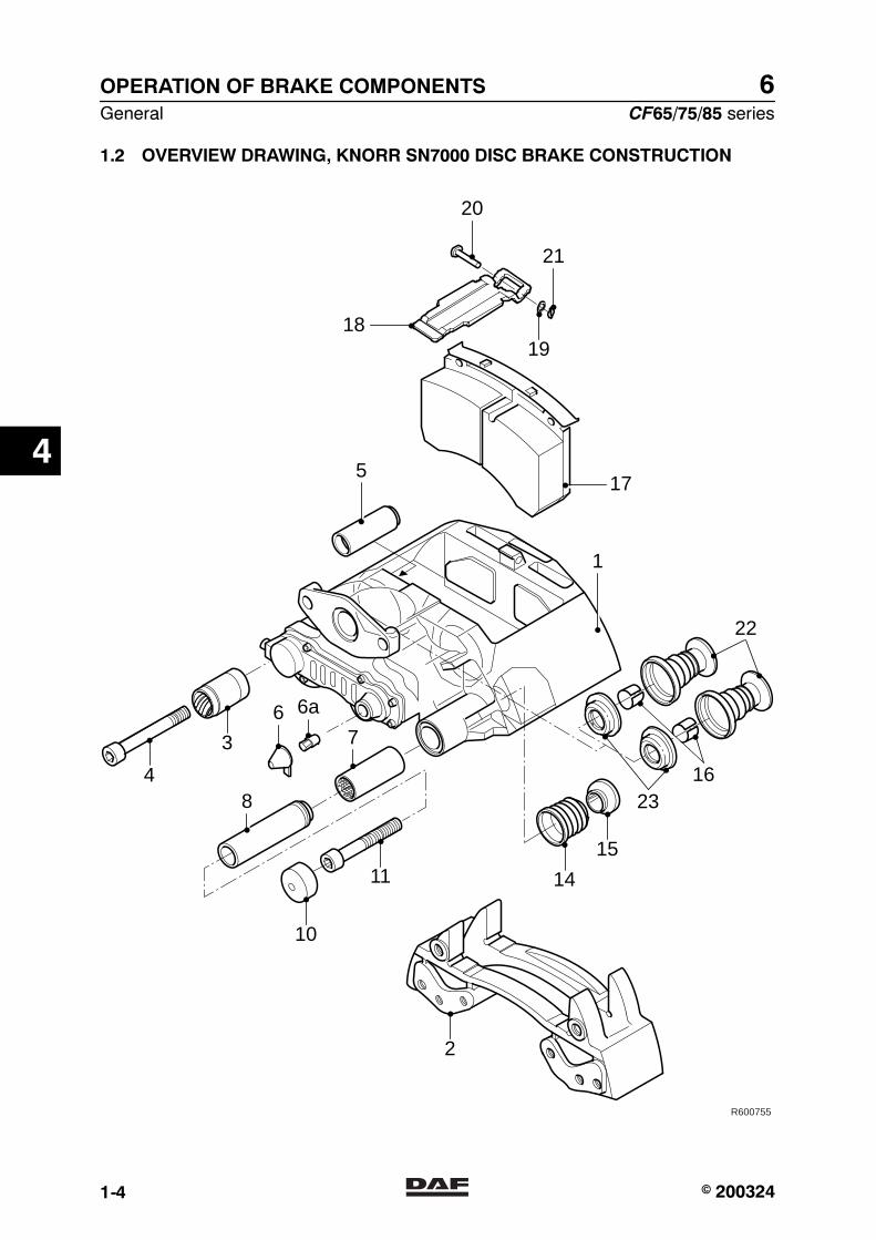
6OPERATION OF BRAKE COMPONENTS
General CF65/75/85 series
1-4
1.2 OVERVIEW DRAWING, KNORR SN7000 DISC BRAKE CONSTRUCTION
R600755
17
22
2316
18
20
21
5
1
6 6a
7
8
19
15
14
2
11
10
4
3
4
� 200324https://www.truck-manuals.net/
6
CF65/75/85 series General
OPERATION OF BRAKE COMPONENTS
1-5
Legend1 Brake saddle2 Brake saddle carrier3 Rubber bearing bush4 Socket head screw5 Guide sleeve6 Cap6a Adapter7 Copper bearing bush8 Guide sleeve10 Protective cover11 Socket head screw14 Bellows15 Washer16 Bearing bushes17 Brake pad18 Attachment bracket19 Lock washer20 Pin21 Retainer clip22 Thrust pieces with bellows23 Sealing rings
4
� 200324https://www.truck-manuals.net/

6OPERATION OF BRAKE COMPONENTS
General CF65/75/85 series
1-6
4
� 200324https://www.truck-manuals.net/

6
CF65/75/85 series Description of components
OPERATION OF BRAKE COMPONENTS
2-1
2. DESCRIPTION OF COMPONENTS
2.1 COMPRESSOR
CF65 seriesThe compressor is a single-cylinder design of225 cm3 with a water-cooled cylinder head. Thecompressor is mounted on the left side of theengine against the flywheel housing.The compressor is driven via a gear wheel fromthe camshaft gear on the flywheel side of theengine.
CF75/85 seriesThe compressor is a two-cylinder design of440 cm3 with a water-cooled cylinder head. Thecompressor is mounted on the right side of theengine against the timing gear case.The compressor is driven by the camshaft gearvia a gear wheel.
The compressor has a so-called energy-savingfunction.When the air-pressure system has reached theset pressure, the pressure regulator in the airdryer will send a pressure signal back to thecompressor head via port 23.In the compressor head, a plunger operates twovalves which connect the inlet and exhaustvalves inside the compressor head.The compressed air is then constantly pumpedinternally from one cylinder to the other.This energy-saving function has a positive effecton the engine efficiency.If the pressure regulator switches off to fill upthe air-pressure system, the plunger will movethe two valves into their initial position, making itpossible for the compressor to supply pressureagain.
4
� 200324https://www.truck-manuals.net/
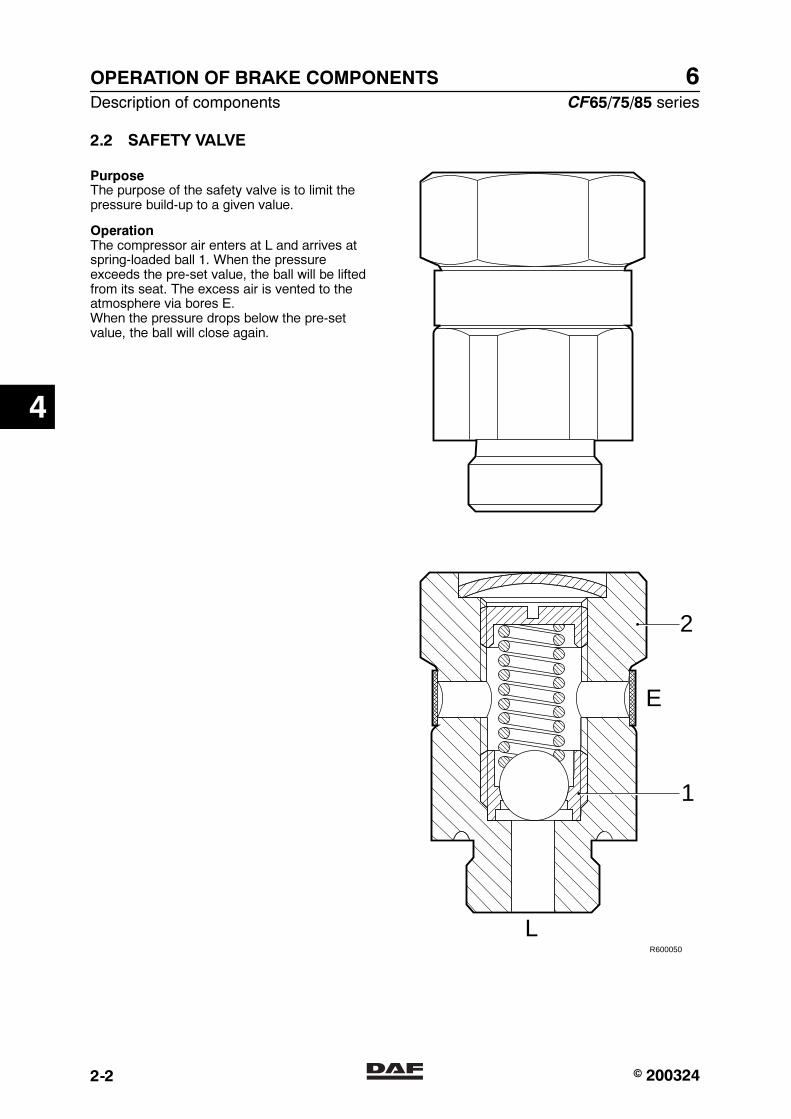
6OPERATION OF BRAKE COMPONENTS
Description of components CF65/75/85 series
2-2
2.2 SAFETY VALVE
PurposeThe purpose of the safety valve is to limit thepressure build-up to a given value.
OperationThe compressor air enters at L and arrives atspring-loaded ball 1. When the pressureexceeds the pre-set value, the ball will be liftedfrom its seat. The excess air is vented to theatmosphere via bores E.When the pressure drops below the pre-setvalue, the ball will close again.
R600050
2
E
L
1
4
� 200324https://www.truck-manuals.net/
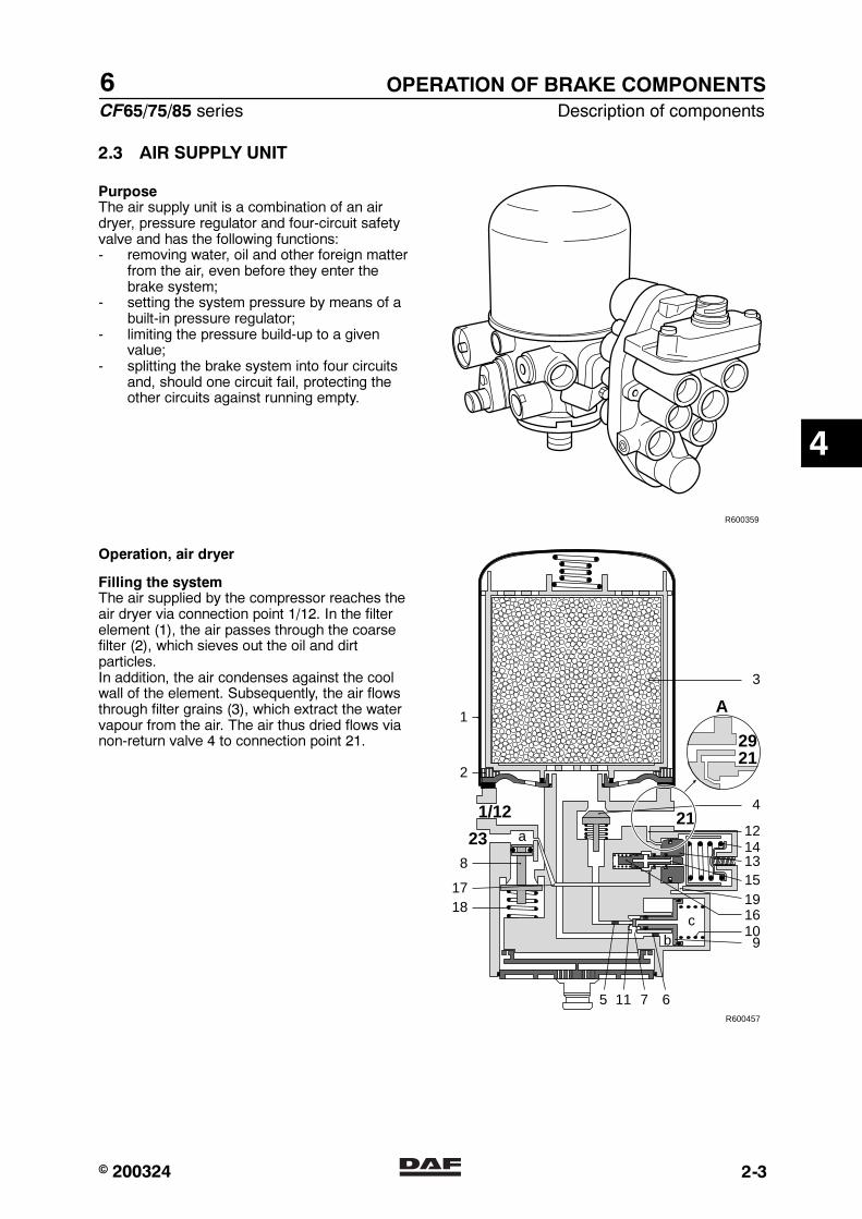
6
CF65/75/85 series Description of components
OPERATION OF BRAKE COMPONENTS
2-3
2.3 AIR SUPPLY UNIT
PurposeThe air supply unit is a combination of an airdryer, pressure regulator and four-circuit safetyvalve and has the following functions:- removing water, oil and other foreign matter
from the air, even before they enter thebrake system;
- setting the system pressure by means of abuilt-in pressure regulator;
- limiting the pressure build-up to a givenvalue;
- splitting the brake system into four circuitsand, should one circuit fail, protecting theother circuits against running empty.
R600359
Operation, air dryer
Filling the systemThe air supplied by the compressor reaches theair dryer via connection point 1/12. In the filterelement (1), the air passes through the coarsefilter (2), which sieves out the oil and dirtparticles.In addition, the air condenses against the coolwall of the element. Subsequently, the air flowsthrough filter grains (3), which extract the watervapour from the air. The air thus dried flows vianon-return valve 4 to connection point 21.
R600457
109
67115
8
bc
a
16
12211/12
23
3
4
2
1
1817
14131519
2921
A
4
� 200324https://www.truck-manuals.net/
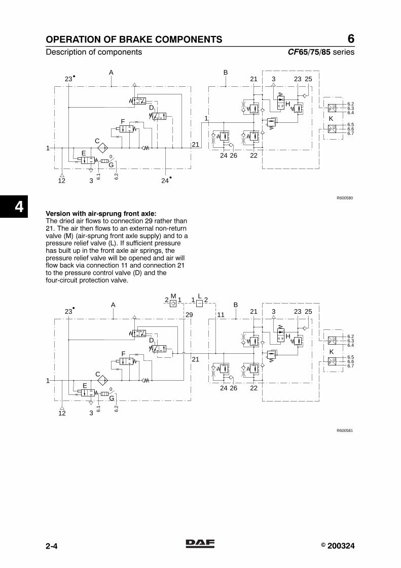
6OPERATION OF BRAKE COMPONENTS
Description of components CF65/75/85 series
2-4
24
21
1F
D H
K
3
A
E
C
G
1
12 24
26 22
2123 3 23 25
P U6.26.36.4
6.1
6.2
P U6.56.66.7
B
R600580
0
Version with air-sprung front axle:The dried air flows to connection 29 rather than21. The air then flows to an external non-returnvalve (M) (air-sprung front axle supply) and to apressure relief valve (L). If sufficient pressurehas built up in the front axle air springs, thepressure relief valve will be opened and air willflow back via connection 11 and connection 21to the pressure control valve (D) and thefour-circuit protection valve.
24
21
2 1M
3
126 22
2129 1123 3 23 25
P U6.26.36.4
6.1
6.2
P U6.56.66.7
R600581
0
1 2L
F
H
K
E
C
G
A B
D
12
4
� 200324https://www.truck-manuals.net/
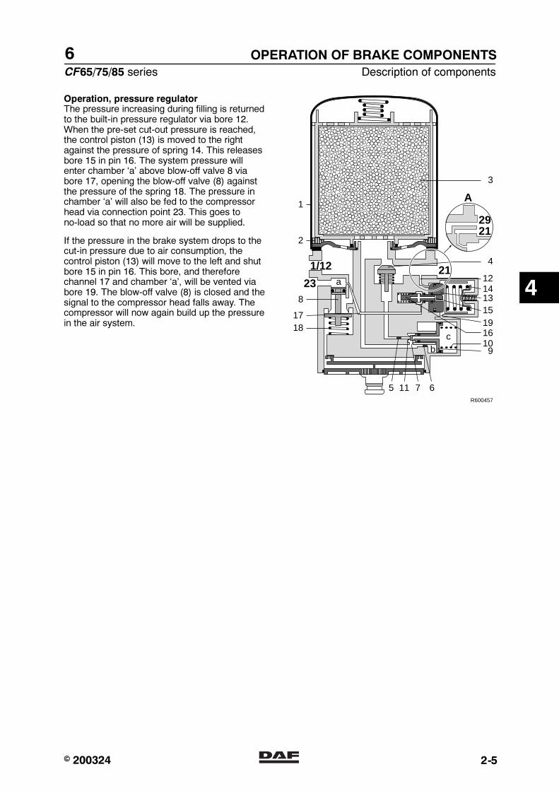
6
CF65/75/85 series Description of components
OPERATION OF BRAKE COMPONENTS
2-5
Operation, pressure regulatorThe pressure increasing during filling is returnedto the built-in pressure regulator via bore 12.When the pre-set cut-out pressure is reached,the control piston (13) is moved to the rightagainst the pressure of spring 14. This releasesbore 15 in pin 16. The system pressure willenter chamber ‘a’ above blow-off valve 8 viabore 17, opening the blow-off valve (8) againstthe pressure of the spring 18. The pressure inchamber ‘a’ will also be fed to the compressorhead via connection point 23. This goes tono-load so that no more air will be supplied.
If the pressure in the brake system drops to thecut-in pressure due to air consumption, thecontrol piston (13) will move to the left and shutbore 15 in pin 16. This bore, and thereforechannel 17 and chamber ‘a’, will be vented viabore 19. The blow-off valve (8) is closed and thesignal to the compressor head falls away. Thecompressor will now again build up the pressurein the air system.
R600457
109
67115
8
bc
a
16
12211/12
23
3
4
2
1
1817
14131519
2921
A
4
� 200324https://www.truck-manuals.net/
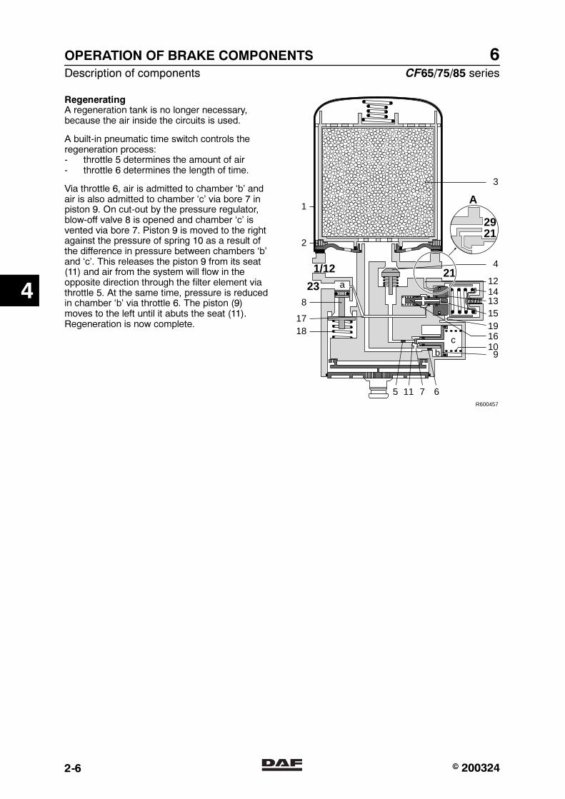
6OPERATION OF BRAKE COMPONENTS
Description of components CF65/75/85 series
2-6
RegeneratingA regeneration tank is no longer necessary,because the air inside the circuits is used.
A built-in pneumatic time switch controls theregeneration process:- throttle 5 determines the amount of air- throttle 6 determines the length of time.
Via throttle 6, air is admitted to chamber ‘b’ andair is also admitted to chamber ‘c’ via bore 7 inpiston 9. On cut-out by the pressure regulator,blow-off valve 8 is opened and chamber ‘c’ isvented via bore 7. Piston 9 is moved to the rightagainst the pressure of spring 10 as a result ofthe difference in pressure between chambers ‘b’and ‘c’. This releases the piston 9 from its seat(11) and air from the system will flow in theopposite direction through the filter element viathrottle 5. At the same time, pressure is reducedin chamber ‘b’ via throttle 6. The piston (9)moves to the left until it abuts the seat (11).Regeneration is now complete.
R600457
109
67115
8
bc
a
16
12211/12
23
3
4
2
1
1817
14131519
2921
A
4
� 200324https://www.truck-manuals.net/

6
CF65/75/85 series Description of components
OPERATION OF BRAKE COMPONENTS
2-7
Operation, four-circuit safety valveThe air supply enters at connection 1(connection 11 on models with air-sprung frontaxle). From there, the air flows to the built-inoverflow valves of circuits 1, 2 and 4.
As soon as the valve of circuit 1 and/or circuit 2opens, the air will be able to flow through tocircuit 3, the trailer vehicle brake and parkingbrake circuit. For reasons of safety, a built-inflow-back function empties circuit 3 when thepressure in circuit 1 is too low. This is done toenable the emergency brake function to beactivated.
24
1
H
K
26 22
21 3 23 25
P U6.26.36.4
P U6.56.66.7
R600476
model with leaf-sprung front axle
24 26 22
21 3 23 25
P U6.26.36.4
P U6.56.66.7
11
R600477
model with air-sprung front axle
4
� 200324https://www.truck-manuals.net/
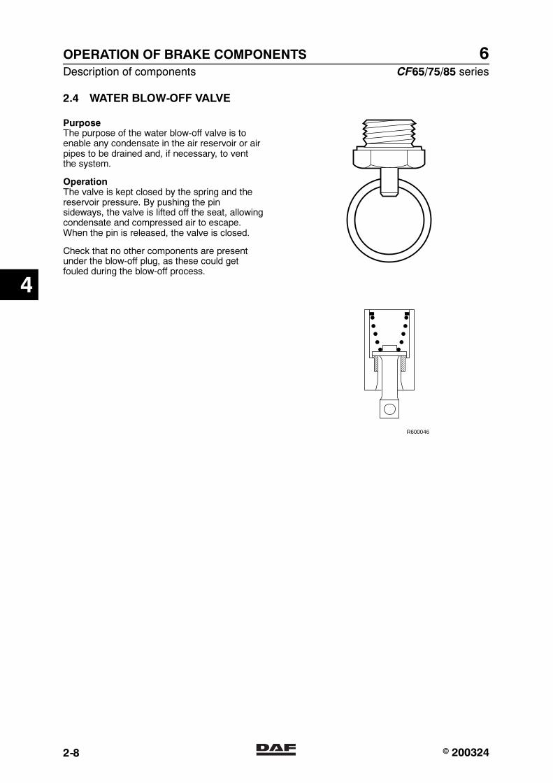
6OPERATION OF BRAKE COMPONENTS
Description of components CF65/75/85 series
2-8
2.4 WATER BLOW-OFF VALVE
PurposeThe purpose of the water blow-off valve is toenable any condensate in the air reservoir or airpipes to be drained and, if necessary, to ventthe system.
OperationThe valve is kept closed by the spring and thereservoir pressure. By pushing the pinsideways, the valve is lifted off the seat, allowingcondensate and compressed air to escape.When the pin is released, the valve is closed.
Check that no other components are presentunder the blow-off plug, as these could getfouled during the blow-off process.
R600046
4
� 200324https://www.truck-manuals.net/
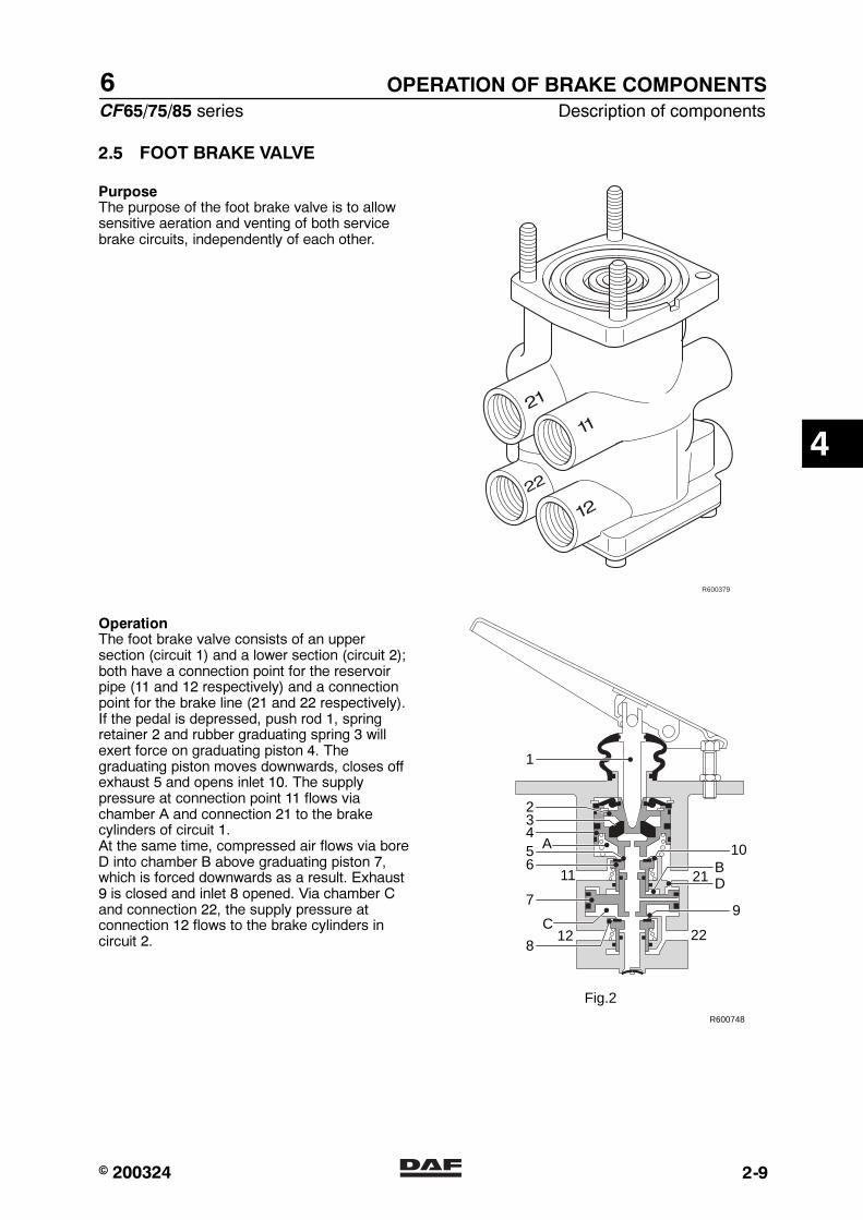
6
CF65/75/85 series Description of components
OPERATION OF BRAKE COMPONENTS
2-9
2.5 FOOT BRAKE VALVE
PurposeThe purpose of the foot brake valve is to allowsensitive aeration and venting of both servicebrake circuits, independently of each other.
R600379
OperationThe foot brake valve consists of an uppersection (circuit 1) and a lower section (circuit 2);both have a connection point for the reservoirpipe (11 and 12 respectively) and a connectionpoint for the brake line (21 and 22 respectively).If the pedal is depressed, push rod 1, springretainer 2 and rubber graduating spring 3 willexert force on graduating piston 4. Thegraduating piston moves downwards, closes offexhaust 5 and opens inlet 10. The supplypressure at connection point 11 flows viachamber A and connection 21 to the brakecylinders of circuit 1.At the same time, compressed air flows via boreD into chamber B above graduating piston 7,which is forced downwards as a result. Exhaust9 is closed and inlet 8 opened. Via chamber Cand connection 22, the supply pressure atconnection 12 flows to the brake cylinders incircuit 2.
21
2212
A
BD
C
10
97
8
65432
1
11
R600748
Fig.2
4
� 200324https://www.truck-manuals.net/
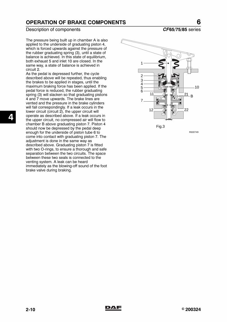
6OPERATION OF BRAKE COMPONENTS
Description of components CF65/75/85 series
2-10
The pressure being built up in chamber A is alsoapplied to the underside of graduating piston 4,which is forced upwards against the pressure ofthe rubber graduating spring (3), until a state ofbalance is achieved. In this state of equilibrium,both exhaust 5 and inlet 10 are closed. In thesame way, a state of balance is achieved incircuit 2.As the pedal is depressed further, the cycledescribed above will be repeated, thus enablingthe brakes to be applied in stages, until themaximum braking force has been applied. If thepedal force is reduced, the rubber graduatingspring (3) will slacken so that graduating pistons4 and 7 move upwards. The brake lines arevented and the pressure in the brake cylinderswill fall correspondingly. If a leak occurs in thelower circuit (circuit 2), the upper circuit willoperate as described above. If a leak occurs inthe upper circuit, no compressed air will flow tochamber B above graduating piston 7. Piston 4should now be depressed by the pedal deepenough for the underside of piston tube 6 tocome into contact with graduating piston 7. Theadjustment is done in the same way asdescribed above. Graduating piston 7 is fittedwith two O-rings, to ensure a thorough and safeseparation between the two circuits. The spacebetween these two seals is connected to theventing system. A leak can be heardimmediately as the blowing-off sound of the footbrake valve during braking.
22
21
12
B
10
7
65432
1
11
R600749
Fig.3
4
� 200324https://www.truck-manuals.net/

6
CF65/75/85 series Description of components
OPERATION OF BRAKE COMPONENTS
2-11
2.6 RELAY VALVE
PurposeThe purpose of the relay valve is to allow fastaeration and venting of the spring brakecylinders and brake cylinders, shortening thebrake reaction/release time.
Note:The hysteresis of the relay valve used for theparking brake is greater and therefore is notsuitable for use in the service brake.
The air reservoir is connected to connectionpoint 1. When connection point 4 ispressureless, inlet 5 is closed and exhaust 6opened. The brake chambers connected toconnection point 2 are now vented.
When compressed air passes throughconnection point 4 into chamber ‘a’ above piston7, the piston is forced downwards. Outlet 6 isclosed and inlet 5 opened. The compressed airnow passes from the air reservoir to the brakechambers.
A state of balance is achieved when thepressures on both sides of piston 7 are equal.Then, both the outlet and the inlet are closed.
When the pressure in connection point 4 andconsequently in chamber ‘a’ drops, piston 7 isforced upwards. Inlet 5 is closed and outlet 6opened and as a consequence the brakechambers are blown off through vent opening 3.
The rubber flap in opening 3 prevents dirt fromentering, whilst providing a large opening for airto be blown off.
R600490
2
1 6
4 A
5
3
7
R600491
2
1 6
4 A
5
3
7
4
� 200324https://www.truck-manuals.net/
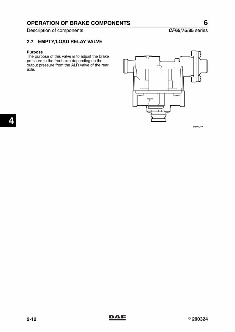
6OPERATION OF BRAKE COMPONENTS
Description of components CF65/75/85 series
2-12
2.7 EMPTY/LOAD RELAY VALVE
PurposeThe purpose of this valve is to adjust the brakepressure to the front axle depending on theoutput pressure from the ALR valve of the rearaxle.
R600049
4
� 200324https://www.truck-manuals.net/
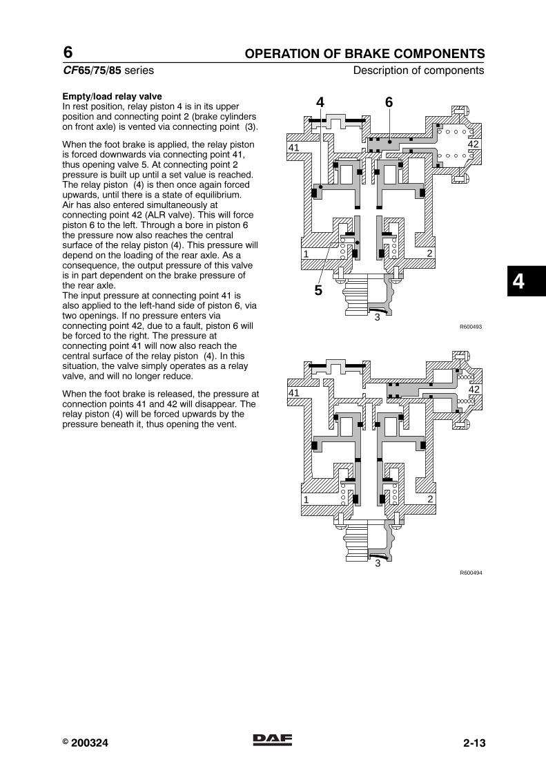
6
CF65/75/85 series Description of components
OPERATION OF BRAKE COMPONENTS
2-13
Empty/load relay valveIn rest position, relay piston 4 is in its upperposition and connecting point 2 (brake cylinderson front axle) is vented via connecting point (3).
When the foot brake is applied, the relay pistonis forced downwards via connecting point 41,thus opening valve 5. At connecting point 2pressure is built up until a set value is reached.The relay piston (4) is then once again forcedupwards, until there is a state of equilibrium.Air has also entered simultaneously atconnecting point 42 (ALR valve). This will forcepiston 6 to the left. Through a bore in piston 6the pressure now also reaches the centralsurface of the relay piston (4). This pressure willdepend on the loading of the rear axle. As aconsequence, the output pressure of this valveis in part dependent on the brake pressure ofthe rear axle.The input pressure at connecting point 41 isalso applied to the left-hand side of piston 6, viatwo openings. If no pressure enters viaconnecting point 42, due to a fault, piston 6 willbe forced to the right. The pressure atconnecting point 41 will now also reach thecentral surface of the relay piston (4). In thissituation, the valve simply operates as a relayvalve, and will no longer reduce.
When the foot brake is released, the pressure atconnection points 41 and 42 will disappear. Therelay piston (4) will be forced upwards by thepressure beneath it, thus opening the vent.
1 2
3
4241
R600493
4 6
5
1 2
3
4241
R600494
4
� 200324https://www.truck-manuals.net/
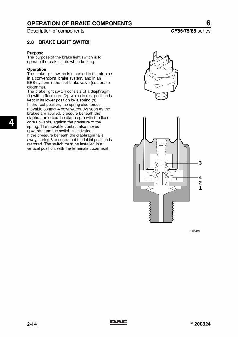
6OPERATION OF BRAKE COMPONENTS
Description of components CF65/75/85 series
2-14
2.8 BRAKE LIGHT SWITCH
PurposeThe purpose of the brake light switch is tooperate the brake lights when braking.
OperationThe brake light switch is mounted in the air pipein a conventional brake system, and in anEBS system in the foot brake valve (see brakediagrams).The brake light switch consists of a diaphragm(1) with a fixed core (2), which in rest position iskept in its lower position by a spring (3).In the rest position, the spring also forcesmovable contact 4 downwards. As soon as thebrakes are applied, pressure beneath thediaphragm forces the diaphragm with the fixedcore upwards, against the pressure of thespring. The movable contact also movesupwards, and the switch is activated.If the pressure beneath the diaphragm fallsaway, spring 3 ensures that the initial position isrestored. The switch must be installed in avertical position, with the terminals uppermost.
3
421
R 600105
4
� 200324https://www.truck-manuals.net/

6
CF65/75/85 series Description of components
OPERATION OF BRAKE COMPONENTS
2-15
2.9 LOAD SENSING VALVE, AIR SUSPENSION
PurposeAutomatic control of the braking force isdependent on the pressure in the bellows andtherefore on the load condition of the vehicle.Thanks to the integrated relay valve, the brakecylinders are aerated and vented quickly.
4341 42
3
21
4
E
C
C
FD
A
G
B
a
nomdgi
j fe l
k
h
c b
R600455
r
s
OperationThe control valve is activated by the pressure ofthe left and right bellows via connection points41 and 42. The actuated piston (i) that movesagainst the pressure of spring ‘j’ brings thetappet (g) to a position that corresponds to theload condition. The arithmetic average of thebellows pressure on the left and right is thedetermining factor in this.
4
� 200324https://www.truck-manuals.net/
6OPERATION OF BRAKE COMPONENTS
Description of components CF65/75/85 series
2-16
The compressed air provided by the foot brakevalve flows via connection point 4 into chamberA, pushing piston ‘b’ to the left. Outlet ‘d’ isclosed and inlet ‘m’ is opened, causingcompressed air to enter chamber C to the left ofdiaphragm ‘e’. Relay piston ‘f’ is operated viaduct F and chamber G.At the same time, compressed air flows throughthe open valve (a) and duct E into chamber D tothe right of diaphragm ‘e’. Due to this control,the output pressure at partial load and lowcontrol pressures is increased (to max. 1.4 bar).If the control pressure increases further, piston‘n’ is moved to the left against the pressure ofspring ‘o’ and valve ‘a’ closes.
As pressure builds up in chamber G, relaypiston ‘f’ is pressed downwards. Outlet ‘h’ closesand inlet ‘k’ opens. The air at connection point 1now flows to the brake cylinders via connectionpoint 2.
Now pressure will start to build up in chamber Bunder relay piston ‘f’. As soon as this pressureis somewhat higher than that in chamber G, thepiston is pushed upwards and closes inlet ‘k’.When piston ‘b’ is moved to the left, the vanes(l) attached to it will gradually loosen thediaphragm (e) from the fixed vanes in the fanhousing. As a result, the effective diaphragmsurface will gradually increase. As soon as theforce of the air to the left of the diaphragmexceeds that to the right, piston ‘b’ will move tothe right. The inlet (m) will be closed and a setposition is reached.
4
� 200324https://www.truck-manuals.net/

6
CF65/75/85 series Description of components
OPERATION OF BRAKE COMPONENTS
2-17
4341 42
3
21
4
E
C
C
FD
A
G
B
a
nomdgi
j fe l
k
h
c b
R600455
r
s
The position of tappet ‘g’, which depends on theposition of piston ‘i’, is indicative of the effectivediaphragm surface and therefore of the outputbrake pressure.The position of tappet ‘g’ determines to whatextent piston ‘b’ must be moved with the vanedisc (l) to allow the valve to build up pressure.Due to this movement, the effective surface ofthe diaphragm will alter.In full-load position, this surface and that ofpiston ‘b’ are equally large. The control pressureat connection point 4 is therefore let through(ratio 1:1) to chambers C and G. The outputpressure at 2 will now equal the control pressureat connection point 4.
4
� 200324https://www.truck-manuals.net/
6OPERATION OF BRAKE COMPONENTS
Description of components CF65/75/85 series
2-18
If the pressure at connection point 4 decreases,the pressure in chamber C will push piston ‘b’ tothe right. Vent ‘d’ will open and the pressure inchambers C and G will fall. The relay piston willbe pushed up due to the pressure still present inchamber B causing vent ‘h’ to open. Thepressure at connection point 2 will now fall viavent 3.
A stop bolt in front of tappet ‘g’ ensures that thisvalve can always provide the minimum brakepressure, if the bellows pressure delivered fallsbelow the minimum effective pressure due to afault. The factory setting of this bolt must not bechanged.
The simulation connection (43) is for checkingthe operation of the valve. By connecting an airhose to it, the bellows will be pneumaticallyclosed, allowing the valve to be operated with arandom test pressure.
4
� 200324https://www.truck-manuals.net/
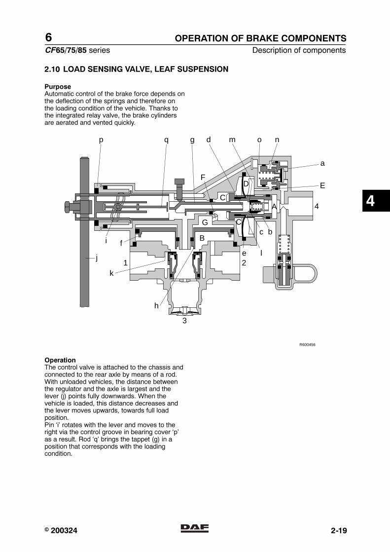
6
CF65/75/85 series Description of components
OPERATION OF BRAKE COMPONENTS
2-19
2.10 LOAD SENSING VALVE, LEAF SUSPENSION
PurposeAutomatic control of the brake force depends onthe deflection of the springs and therefore onthe loading condition of the vehicle. Thanks tothe integrated relay valve, the brake cylindersare aerated and vented quickly.
3
21
4
E
C
C
FD
A
G
B
a
nomdgq
j
i fe l
k
p
h
c b
R600456
OperationThe control valve is attached to the chassis andconnected to the rear axle by means of a rod.With unloaded vehicles, the distance betweenthe regulator and the axle is largest and thelever (j) points fully downwards. When thevehicle is loaded, this distance decreases andthe lever moves upwards, towards full loadposition.Pin ‘i’ rotates with the lever and moves to theright via the control groove in bearing cover ‘p’as a result. Rod ‘q’ brings the tappet (g) in aposition that corresponds with the loadingcondition.
4
� 200324https://www.truck-manuals.net/
6OPERATION OF BRAKE COMPONENTS
Description of components CF65/75/85 series
2-20
The compressed air provided by the foot brakevalve flows via connection point 4 into chamberA, pushing piston ‘b’ to the left. Outlet ‘d’ isclosed and inlet ‘m’ is opened, causingcompressed air to enter chamber C to the left ofdiaphragm ‘e’. Relay piston ‘f’ is operated viaduct F and chamber G.At the same time, compressed air flows throughthe open valve (a) and duct E into chamber D tothe right of diaphragm ‘e’. Due to this control,the output pressure at partial load and lowcontrol pressures is increased (to max. 1.4 bar).If the control pressure increases further, piston‘n’ is moved to the left against the pressure ofspring ‘o’ and valve ‘a’ closes.
As pressure builds up in chamber G, relaypiston ‘f’ is pressed downwards. Outlet ‘h’ closesand inlet ‘k’ opens. The air at connection point 1now flows to the brake cylinders via connectionpoint 2.
Now pressure will start to build up in chamber Bunder relay piston ‘f’. As soon as this pressureis somewhat higher than that in chamber G, thepiston is pushed upwards and closes inlet ‘k’.
4
� 200324https://www.truck-manuals.net/
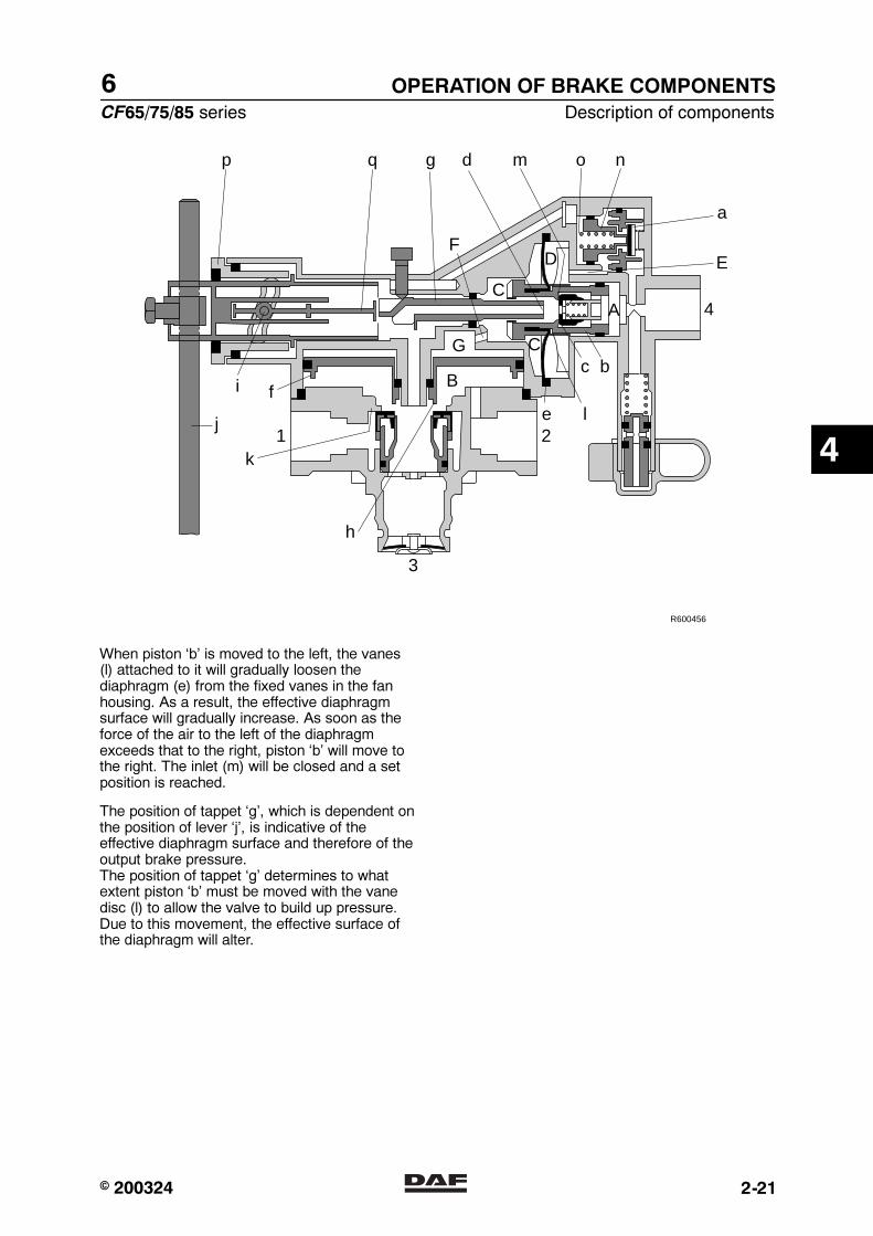
6
CF65/75/85 series Description of components
OPERATION OF BRAKE COMPONENTS
2-21
3
21
4
E
C
C
FD
A
G
B
a
nomdgq
j
i fe l
k
p
h
c b
R600456
When piston ‘b’ is moved to the left, the vanes(l) attached to it will gradually loosen thediaphragm (e) from the fixed vanes in the fanhousing. As a result, the effective diaphragmsurface will gradually increase. As soon as theforce of the air to the left of the diaphragmexceeds that to the right, piston ‘b’ will move tothe right. The inlet (m) will be closed and a setposition is reached.
The position of tappet ‘g’, which is dependent onthe position of lever ‘j’, is indicative of theeffective diaphragm surface and therefore of theoutput brake pressure.The position of tappet ‘g’ determines to whatextent piston ‘b’ must be moved with the vanedisc (l) to allow the valve to build up pressure.Due to this movement, the effective surface ofthe diaphragm will alter.
4
� 200324https://www.truck-manuals.net/

6OPERATION OF BRAKE COMPONENTS
Description of components CF65/75/85 series
2-22
In full-load position, this surface and that ofpiston ‘b’ are equally large. The control pressureat connection point 4 is therefore let through(ratio 1:1) to chambers C and G. The outputpressure at 2 will now equal the control pressureat connection point 4.
If the pressure at connection point 4 decreases,the pressure in chamber C will push piston ‘b’ tothe right. Vent ‘d’ will open and the pressure inchambers C and G will fall. The relay piston willbe pushed up due to the pressure still present inchamber B causing vent ‘h’ to open. Thepressure at connection point 2 will now fall viavent 3.
A stop bolt in front of tappet g ensures that thisvalve can always provide the minimum brakepressure if lever ‘j’ is in too low a position due toa fault. The factory setting of this bolt must notbe changed.
4
� 200324https://www.truck-manuals.net/
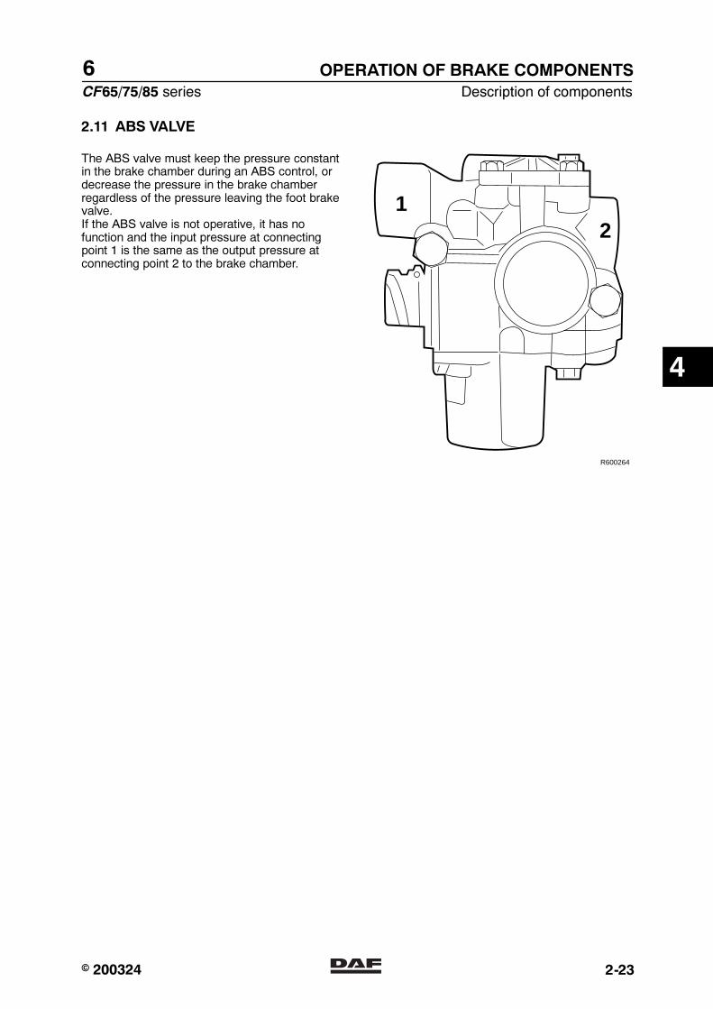
6
CF65/75/85 series Description of components
OPERATION OF BRAKE COMPONENTS
2-23
2.11 ABS VALVE
The ABS valve must keep the pressure constantin the brake chamber during an ABS control, ordecrease the pressure in the brake chamberregardless of the pressure leaving the foot brakevalve.If the ABS valve is not operative, it has nofunction and the input pressure at connectingpoint 1 is the same as the output pressure atconnecting point 2 to the brake chamber.
12
R600264
4
� 200324https://www.truck-manuals.net/

6OPERATION OF BRAKE COMPONENTS
Description of components CF65/75/85 series
2-24
Increasing pressure at connecting point 2Input pressure at connection point 1 comingfrom the foot brake valve will lift diaphragm 5from the seat (7), causing the brake pressurevia connection point 2 to be guided to the brakechamber.The input pressure will also be guided through abore past the magnet coil (10) in chamber 19under diaphragm 6, causing diaphragm 6 toform a seal on seat 8. This will close connectionpoint 2 from the vent.
Reducing pressure at connecting point 2By activating magnet coil 9, solenoid valve 11will open bore 15 and close bore 22. As a result,input pressure enters chamber 15 abovediaphragm 5 via a bore. Diaphragm 5 sealsagainst seat 7, so that no more pressure canbuild up.By activating the magnet coil 10 at the sametime, bore 16 opens and bore 23 closes.By opening bore 16, the pressure underdiaphragm 6 can be reduced via the vent. Thepressure in the brake chamber can now escapevia connection point 2, chamber 20 and aninternal bore to the vent.
Maintaining pressure at connecting point 2By deactivating magnet coil 10, the inputpressure can be guided via a bore past magnetcoil 10 into chamber 19 under diaphragm 6, thussealing off diaphragm 6.The pressure in the brake chamber can now nolonger be guided to the vent via chamber 20.This keeps the pressure in the brake chamberconstant.
610
6
8
19
19
20
16
7
5
7
5
10
22
1115
9
12
15
23
10
12
23
1
2
2
1
2
1
6
19
20
16
R600019
4
� 200324https://www.truck-manuals.net/

6
CF65/75/85 series Description of components
OPERATION OF BRAKE COMPONENTS
2-25
2.12 TWO-WAY VALVE
This valve is used in drum brakes as adouble-check valve, that is to say a safetymeasure so that the maximum service brakeand parking brake cannot operate the wheelbrakes at the same time.
PurposeThe purpose of this valve is to let throughunchanged the highest of two submittedpressure signals.
OperationWhen pressure is applied to one of theentrances or if the pressure on one entrance ishigher than on the other, the little piston will shutoff the other entrance and the air can leave thevalve unhindered via the entrance again.No connection can be established between thetwo inlets.
11 21
12
R600747
4
� 200324https://www.truck-manuals.net/
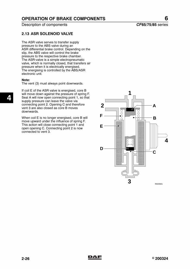
6OPERATION OF BRAKE COMPONENTS
Description of components CF65/75/85 series
2-26
2.13 ASR SOLENOID VALVE
The ASR valve serves to transfer supplypressure to the ABS valve during anASR differential brake control. Depending on theslip, the ABS valve will control the brakepressure to the respective brake chamber.The ASR-valve is a simple electropneumaticvalve, which is normally closed, that transfers airpressure when it is electrically energised.The energising is controlled by the ABS/ASRelectronic unit.
Note:The vent (3) must always point downwards.
If coil E of the ASR valve is energised, core Bwill move down against the pressure of spring F.Seal A will now open connecting point 1, so thatsupply pressure can leave the valve viaconnecting point 2. Opening C and thereforevent 3 are also closed as core B movesdownwards.
When coil E is no longer energised, core B willmove upward under the influence of spring F.This action will close connecting point 1 andopen opening C. Connecting point 2 is nowconnected to vent 3.
R600601
2
3
C
B
D
E
F
A
1
4
4
� 200324https://www.truck-manuals.net/
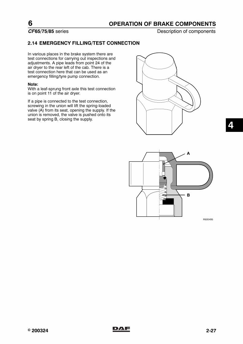
6
CF65/75/85 series Description of components
OPERATION OF BRAKE COMPONENTS
2-27
2.14 EMERGENCY FILLING/TEST CONNECTION
In various places in the brake system there aretest connections for carrying out inspections andadjustments. A pipe leads from point 24 of theair dryer to the rear left of the cab. There is atest connection here that can be used as anemergency filling/tyre pump connection.
Note:With a leaf-sprung front axle this test connectionis on point 11 of the air dryer.
If a pipe is connected to the test connection,screwing in the union will lift the spring-loadedvalve (A) from its seat, opening the supply. If theunion is removed, the valve is pushed onto itsseat by spring B, closing the supply.
A
B
R600495
4
� 200324https://www.truck-manuals.net/
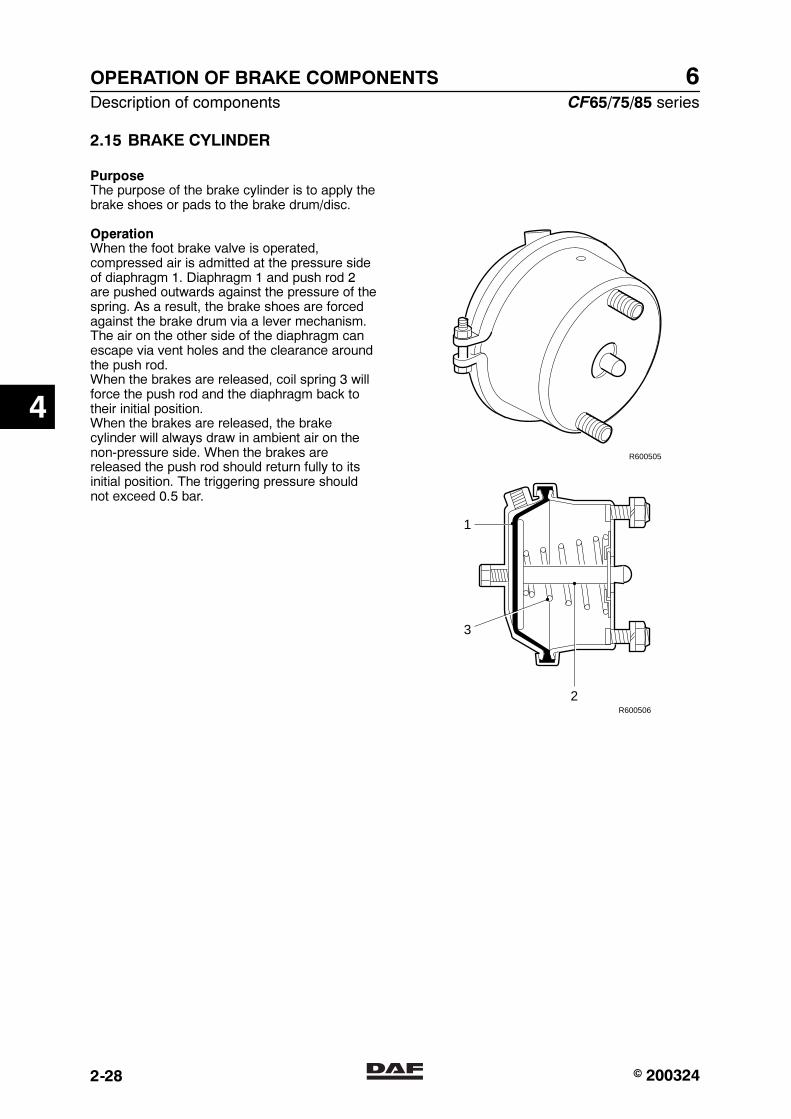
6OPERATION OF BRAKE COMPONENTS
Description of components CF65/75/85 series
2-28
2.15 BRAKE CYLINDER
PurposeThe purpose of the brake cylinder is to apply thebrake shoes or pads to the brake drum/disc.
OperationWhen the foot brake valve is operated,compressed air is admitted at the pressure sideof diaphragm 1. Diaphragm 1 and push rod 2are pushed outwards against the pressure of thespring. As a result, the brake shoes are forcedagainst the brake drum via a lever mechanism.The air on the other side of the diaphragm canescape via vent holes and the clearance aroundthe push rod.When the brakes are released, coil spring 3 willforce the push rod and the diaphragm back totheir initial position.When the brakes are released, the brakecylinder will always draw in ambient air on thenon-pressure side. When the brakes arereleased the push rod should return fully to itsinitial position. The triggering pressure shouldnot exceed 0.5 bar.
R600505
2
1
3
R600506
4
� 200324https://www.truck-manuals.net/
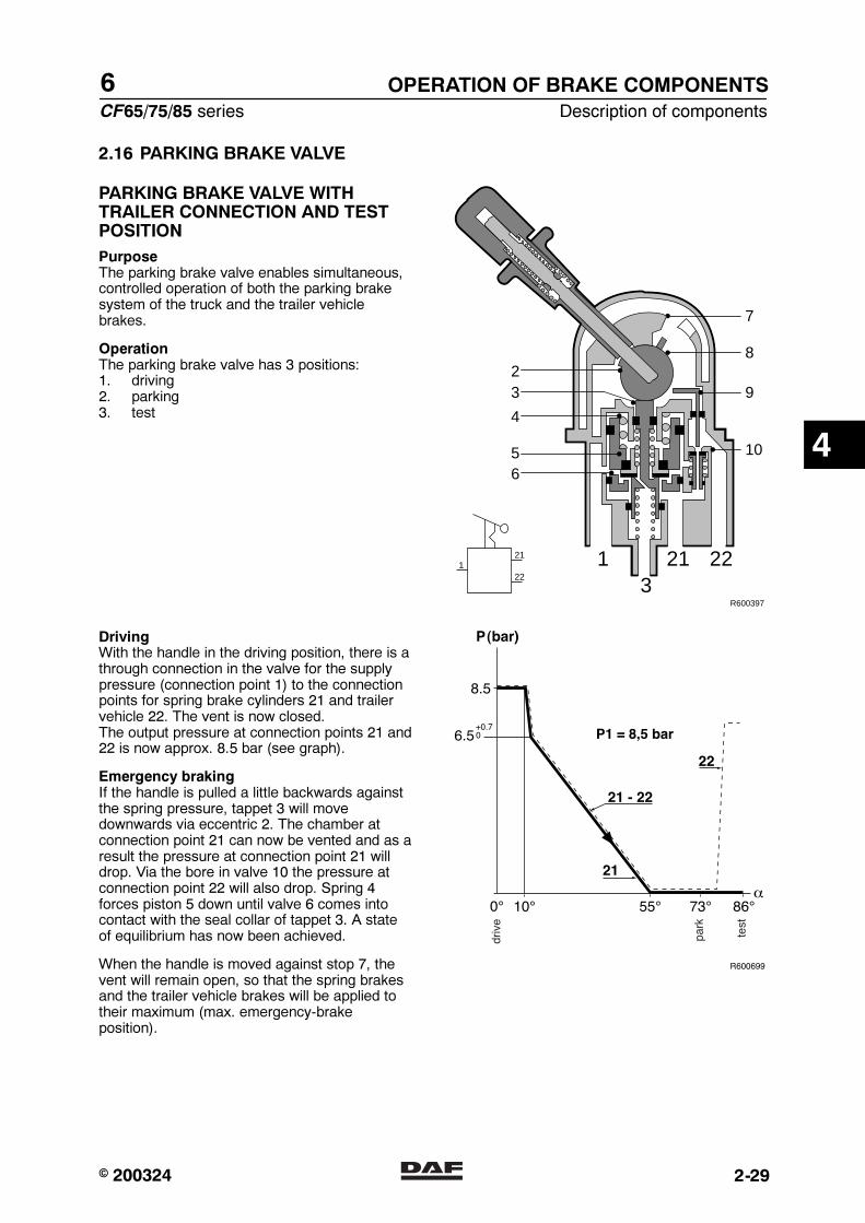
6
CF65/75/85 series Description of components
OPERATION OF BRAKE COMPONENTS
2-29
2.16 PARKING BRAKE VALVE
PARKING BRAKE VALVE WITHTRAILER CONNECTION AND TESTPOSITION
PurposeThe parking brake valve enables simultaneous,controlled operation of both the parking brakesystem of the truck and the trailer vehiclebrakes.
OperationThe parking brake valve has 3 positions:1. driving2. parking3. test
3211 22
23
5
4
6
8
7
9
10
R600397
121
22
DrivingWith the handle in the driving position, there is athrough connection in the valve for the supplypressure (connection point 1) to the connectionpoints for spring brake cylinders 21 and trailervehicle 22. The vent is now closed.The output pressure at connection points 21 and22 is now approx. 8.5 bar (see graph).
Emergency brakingIf the handle is pulled a little backwards againstthe spring pressure, tappet 3 will movedownwards via eccentric 2. The chamber atconnection point 21 can now be vented and as aresult the pressure at connection point 21 willdrop. Via the bore in valve 10 the pressure atconnection point 22 will also drop. Spring 4forces piston 5 down until valve 6 comes intocontact with the seal collar of tappet 3. A stateof equilibrium has now been achieved.
When the handle is moved against stop 7, thevent will remain open, so that the spring brakesand the trailer vehicle brakes will be applied totheir maximum (max. emergency-brakeposition).
4
� 200324https://www.truck-manuals.net/
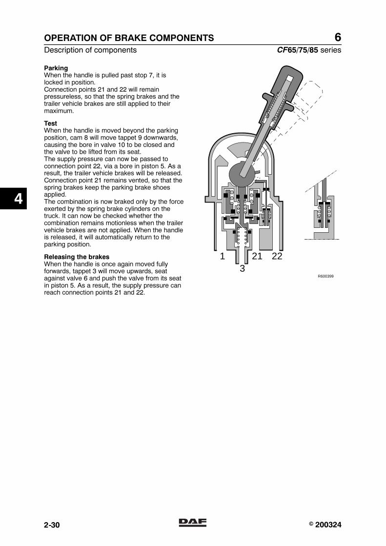
6OPERATION OF BRAKE COMPONENTS
Description of components CF65/75/85 series
2-30
ParkingWhen the handle is pulled past stop 7, it islocked in position.Connection points 21 and 22 will remainpressureless, so that the spring brakes and thetrailer vehicle brakes are still applied to theirmaximum.
TestWhen the handle is moved beyond the parkingposition, cam 8 will move tappet 9 downwards,causing the bore in valve 10 to be closed andthe valve to be lifted from its seat.The supply pressure can now be passed toconnection point 22, via a bore in piston 5. As aresult, the trailer vehicle brakes will be released.Connection point 21 remains vented, so that thespring brakes keep the parking brake shoesapplied.The combination is now braked only by the forceexerted by the spring brake cylinders on thetruck. It can now be checked whether thecombination remains motionless when the trailervehicle brakes are not applied. When the handleis released, it will automatically return to theparking position.
Releasing the brakesWhen the handle is once again moved fullyforwards, tappet 3 will move upwards, seatagainst valve 6 and push the valve from its seatin piston 5. As a result, the supply pressure canreach connection points 21 and 22.
3211 22
R600399
4
� 200324https://www.truck-manuals.net/
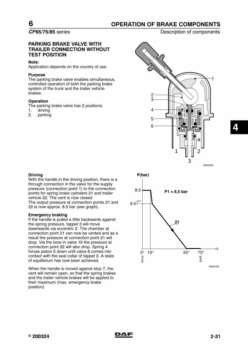
6
CF65/75/85 series Description of components
OPERATION OF BRAKE COMPONENTS
2-31
PARKING BRAKE VALVE WITHTRAILER CONNECTION WITHOUTTEST POSITION
Note:Application depends on the country of use.
PurposeThe parking brake valve enables simultaneous,controlled operation of both the parking brakesystem of the truck and the trailer vehiclebrakes.
OperationThe parking brake valve has 2 positions:1. driving2. parking
R600095
2
7
3
4
5
6
1
3
2
a
DrivingWith the handle in the driving position, there is athrough connection in the valve for the supplypressure (connection point 1) to the connectionpoints for spring brake cylinders 21 and trailervehicle 22. The vent is now closed.The output pressure at connection points 21 and22 is now approx. 8.5 bar (see graph).
Emergency brakingIf the handle is pulled a little backwards againstthe spring pressure, tappet 3 will movedownwards via eccentric 2. The chamber atconnection point 21 can now be vented and as aresult the pressure at connection point 21 willdrop. Via the bore in valve 10 the pressure atconnection point 22 will also drop. Spring 4forces piston 5 down until valve 6 comes intocontact with the seal collar of tappet 3. A stateof equilibrium has now been achieved.
When the handle is moved against stop 7, thevent will remain open, so that the spring brakesand the trailer vehicle brakes will be applied totheir maximum (max. emergency-brakeposition).
4
� 200324https://www.truck-manuals.net/
6OPERATION OF BRAKE COMPONENTS
Description of components CF65/75/85 series
2-32
ParkingWhen the handle is pulled past stop 7, it islocked in position.Connection point 21 is still pressureless.Connection point 22 is connected to thereservoir connection via a bore in piston 5 andvalve 10, which has been pushed from its seatby tappet 9. The combination is now braked onlyby the force exerted by the spring brakecylinders on the truck.
Releasing the brakesWhen the handle is once again moved fullyforwards, tappet 3 will move upwards, seatagainst valve 6 and push the valve from its seatin piston 5. As a result, the supply pressure canreach connection points 21 and 22.
4
� 200324https://www.truck-manuals.net/

6
CF65/75/85 series Description of components
OPERATION OF BRAKE COMPONENTS
2-33
2.17 LOW-PRESSURE SWITCH
PurposeThe purpose of the low-pressure switch is toswitch off the warning lights when a pre-setpressure is reached.
1. Diaphragm2. Switch3. Contact4. Contact5. Thrust pin
51
2
3 4
R 600106
OperationIf the pre-set pressure in the air pipe is reached,the existing connection of both contacts 3 and 4is cut off by diaphragm 1. If the pressure fallsbelow the pre-set value, both contacts areconnected again.
4
� 200324https://www.truck-manuals.net/
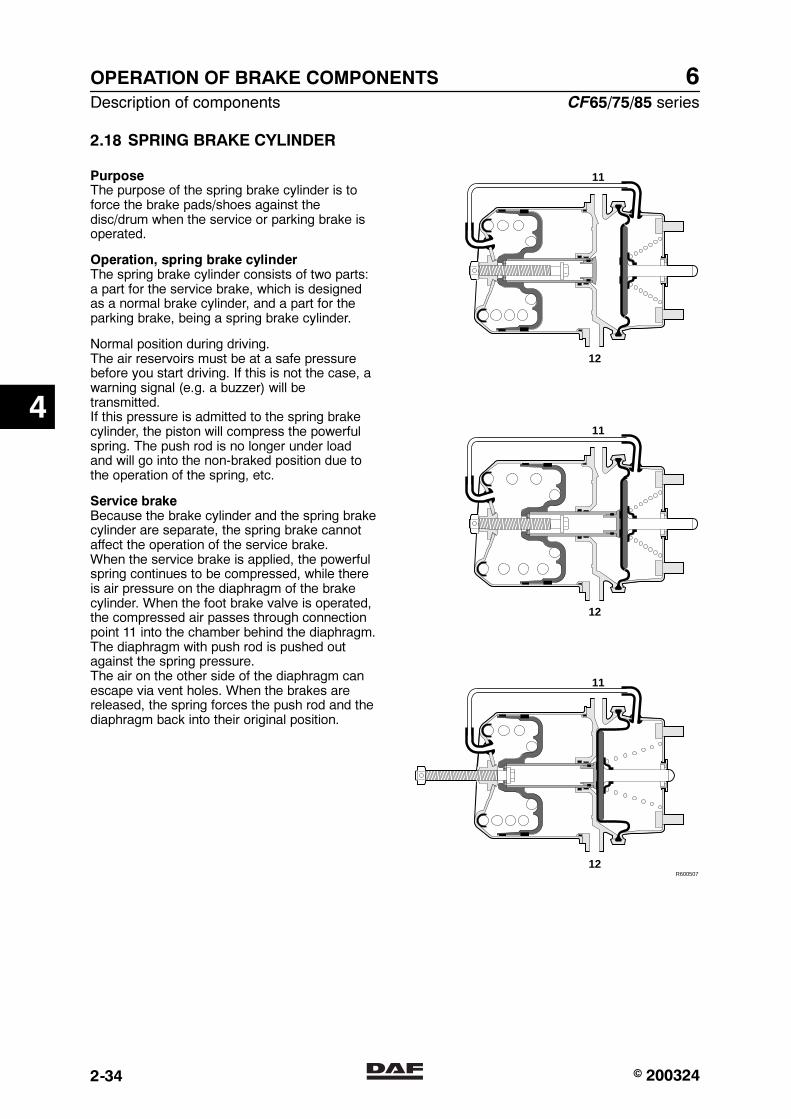
6OPERATION OF BRAKE COMPONENTS
Description of components CF65/75/85 series
2-34
2.18 SPRING BRAKE CYLINDER
PurposeThe purpose of the spring brake cylinder is toforce the brake pads/shoes against thedisc/drum when the service or parking brake isoperated.
Operation, spring brake cylinderThe spring brake cylinder consists of two parts:a part for the service brake, which is designedas a normal brake cylinder, and a part for theparking brake, being a spring brake cylinder.
Normal position during driving.The air reservoirs must be at a safe pressurebefore you start driving. If this is not the case, awarning signal (e.g. a buzzer) will betransmitted.If this pressure is admitted to the spring brakecylinder, the piston will compress the powerfulspring. The push rod is no longer under loadand will go into the non-braked position due tothe operation of the spring, etc.
Service brakeBecause the brake cylinder and the spring brakecylinder are separate, the spring brake cannotaffect the operation of the service brake.When the service brake is applied, the powerfulspring continues to be compressed, while thereis air pressure on the diaphragm of the brakecylinder. When the foot brake valve is operated,the compressed air passes through connectionpoint 11 into the chamber behind the diaphragm.The diaphragm with push rod is pushed outagainst the spring pressure.The air on the other side of the diaphragm canescape via vent holes. When the brakes arereleased, the spring forces the push rod and thediaphragm back into their original position.
11
12
11
12
11
12
R600507
4
� 200324https://www.truck-manuals.net/

6
CF65/75/85 series Description of components
OPERATION OF BRAKE COMPONENTS
2-35
Parking brakeConnection point 12 is vented.The powerful spring then forces the piston withthe piston tube against the diaphragm, so thatthe push rod is forced outwards. Here, use ismade of the continuously available energy of thecompressed, powerful spring.
Release tool, spring brake cylinder withunscrewable release boltIf, due to a failure, no compressed air isavailable in the spring brake cylinder, the vehiclebrakes are automatically applied.But it must still be possible to tow the vehicle.The spring brake cylinder is therefore fitted witha release bolt at the rear. By turning this boltanticlockwise using a spanner, the powerfulspring will be compressed.As the bolt is provided with a thrust bearing, thetorque required is not more than 20 - 40 Nm.Do not use a pneumatic spanner for thispurpose.
Because the spring brakes havebeen released mechanically, theparking brake can no longer beapplied.
Once the failure has been remedied andsufficient compressed air is available, the controlvalve can be used to again admit air into thespring brake cylinder.The release bolt should then be screwed back inwith the spanner and tightened to the specifiedtorque. See “Technical data”. The pressure inthe spring brake cylinder circuit should be atleast 6.5 bar.
11
12
11
12
11
12
R600507
4
� 200324https://www.truck-manuals.net/
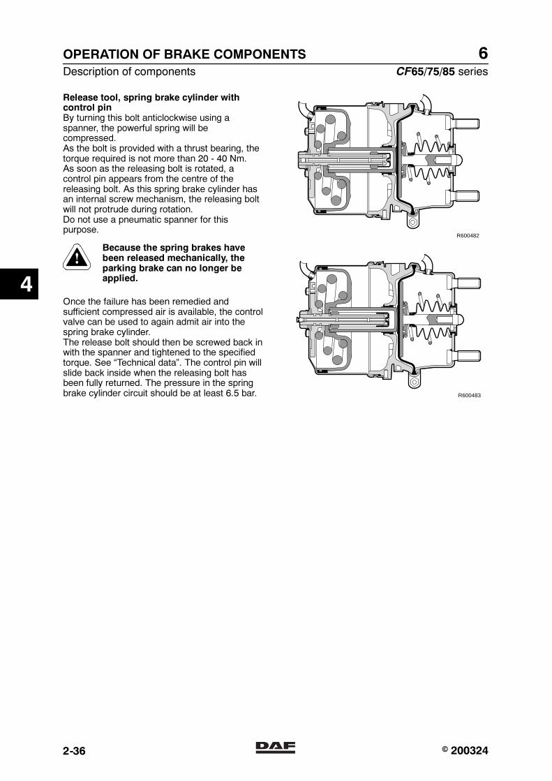
6OPERATION OF BRAKE COMPONENTS
Description of components CF65/75/85 series
2-36
Release tool, spring brake cylinder withcontrol pinBy turning this bolt anticlockwise using aspanner, the powerful spring will becompressed.As the bolt is provided with a thrust bearing, thetorque required is not more than 20 - 40 Nm.As soon as the releasing bolt is rotated, acontrol pin appears from the centre of thereleasing bolt. As this spring brake cylinder hasan internal screw mechanism, the releasing boltwill not protrude during rotation.Do not use a pneumatic spanner for thispurpose.
Because the spring brakes havebeen released mechanically, theparking brake can no longer beapplied.
Once the failure has been remedied andsufficient compressed air is available, the controlvalve can be used to again admit air into thespring brake cylinder.The release bolt should then be screwed back inwith the spanner and tightened to the specifiedtorque. See “Technical data”. The control pin willslide back inside when the releasing bolt hasbeen fully returned. The pressure in the springbrake cylinder circuit should be at least 6.5 bar.
R600482
R600483
4
� 200324https://www.truck-manuals.net/

6
CF65/75/85 series Description of components
OPERATION OF BRAKE COMPONENTS
2-37
2.19 TRAILER VEHICLE CONTROL VALVE
PurposeThe purpose of the trailer vehicle control valve isto pass on the brake commands from the truckto the trailer vehicle.
41
42
431112
22
R600335
Operation
DrivingConnection point 11 is connected with areservoir and connection point 43 with theparking brake valve. Both are pressurised and ina state of equilibrium. The service coupling headcommunicates with the ambient air viaconnecting point 22, valve 8 and the vent withdamper.
R600340
4
� 200324https://www.truck-manuals.net/
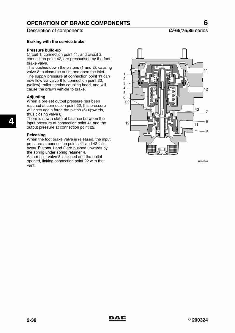
6OPERATION OF BRAKE COMPONENTS
Description of components CF65/75/85 series
2-38
Braking with the service brake
Pressure build-upCircuit 1, connection point 41, and circuit 2,connection point 42, are pressurised by the footbrake valve.This pushes down the pistons (1 and 2), causingvalve 8 to close the outlet and open the inlet.The supply pressure at connection point 11 cannow flow via valve 8 to connection point 22,(yellow) trailer service coupling head, and willcause the drawn vehicle to brake.
AdjustingWhen a pre-set output pressure has beenreached at connection point 22, this pressurewill once again force the piston (5) upwards,thus closing valve 8.There is now a state of balance between theinput pressure at connection point 41 and theoutput pressure at connection point 22.
ReleasingWhen the foot brake valve is released, the inputpressure at connection points 41 and 42 fallsaway. Pistons 1 and 2 are pushed upwards bythe spring under spring retainer 4.As a result, valve 8 is closed and the outletopened, linking connection point 22 with thevent.
R600340
4
� 200324https://www.truck-manuals.net/
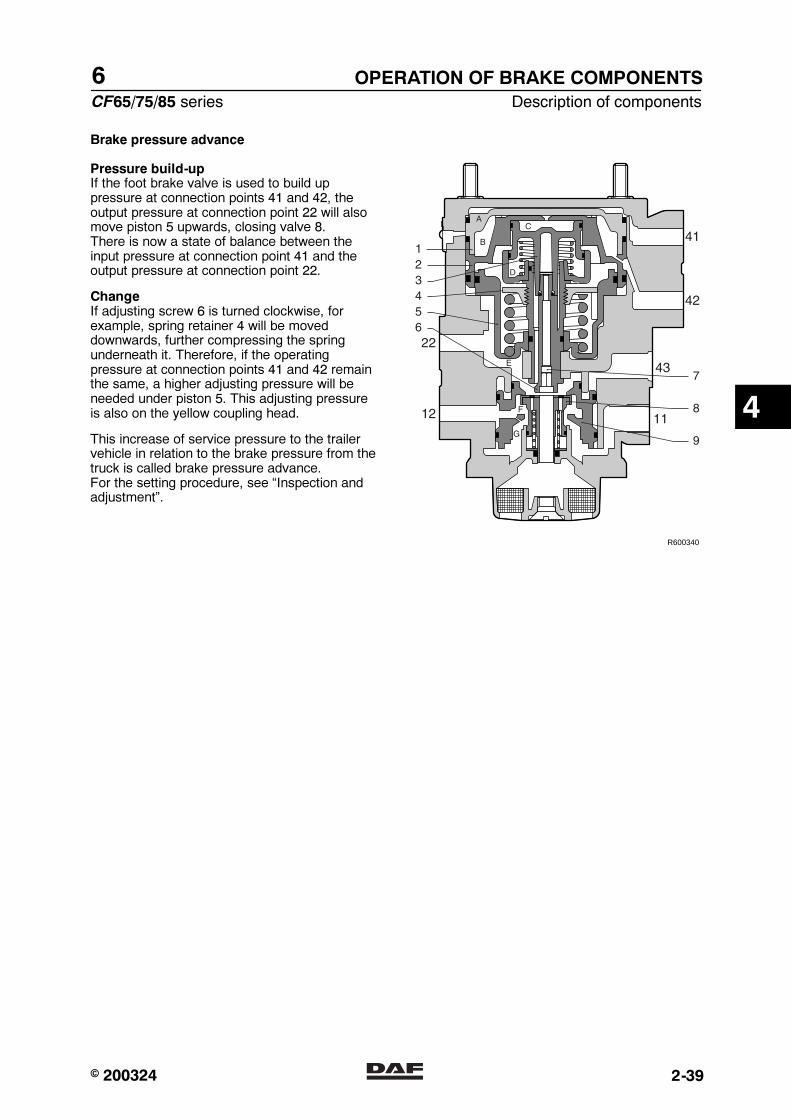
6
CF65/75/85 series Description of components
OPERATION OF BRAKE COMPONENTS
2-39
Brake pressure advance
Pressure build-upIf the foot brake valve is used to build uppressure at connection points 41 and 42, theoutput pressure at connection point 22 will alsomove piston 5 upwards, closing valve 8.There is now a state of balance between theinput pressure at connection point 41 and theoutput pressure at connection point 22.
ChangeIf adjusting screw 6 is turned clockwise, forexample, spring retainer 4 will be moveddownwards, further compressing the springunderneath it. Therefore, if the operatingpressure at connection points 41 and 42 remainthe same, a higher adjusting pressure will beneeded under piston 5. This adjusting pressureis also on the yellow coupling head.
This increase of service pressure to the trailervehicle in relation to the brake pressure from thetruck is called brake pressure advance.For the setting procedure, see “Inspection andadjustment”.
R600340
4
� 200324https://www.truck-manuals.net/

6OPERATION OF BRAKE COMPONENTS
Description of components CF65/75/85 series
2-40
Emergency brakeWhen the parking brake valve is moved into thelocking position, connection point 43 will begradually vented.Piston 9 moves upwards and valve 8 is opened.Depending on the drop in pressure atconnection point 43, a pressure build-up willoccur at connection point 22. When a pre-setvalue has been reached, valve 8 will close sothat a state of equilibrium is achieved.
Parking brakeWhen the parking brake valve is in its maximumposition, i.e. the position at which the lever isblocked, connection point 43 is vented. As aconsequence, there is still an output pressure atconnection 22.
Protection against breakage of service lineDuring braking pressure will be built up onconnection point 22. The air needed for this issupplied from connection point 11.If the service line is broken, pressure will notbuild up in chamber E, which will cause piston 9to move up and close against the bottom ofvalve 8. The supply from connection point 11stagnates, causing pressure to be deliveredfrom connection point 12.The pressure in the reservoir pipe drops and thetrailer vehicle brakes are applied.
R600340
4
� 200324https://www.truck-manuals.net/
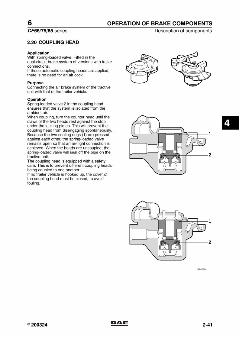
6
CF65/75/85 series Description of components
OPERATION OF BRAKE COMPONENTS
2-41
2.20 COUPLING HEAD
ApplicationWith spring-loaded valve. Fitted in thedual-circuit brake system of versions with trailerconnections.If these automatic coupling heads are applied,there is no need for an air cock.
PurposeConnecting the air brake system of the tractiveunit with that of the trailer vehicle.
OperationSpring-loaded valve 2 in the coupling headensures that the system is isolated from theambient air.When coupling, turn the counter head until theclaws of the two heads rest against the stopunder the locking plates. This will prevent thecoupling head from disengaging spontaneously.Because the two sealing rings (1) are pressedagainst each other, the spring-loaded valveremains open so that an air-tight connection isachieved. When the heads are uncoupled, thespring-loaded valve will seal off the pipe on thetractive unit.The coupling head is equipped with a safetycam. This is to prevent different coupling headsbeing coupled to one another.If no trailer vehicle is hooked up, the cover ofthe coupling head must be closed, to avoidfouling.
R600101
2
1
2
1
4
� 200324https://www.truck-manuals.net/
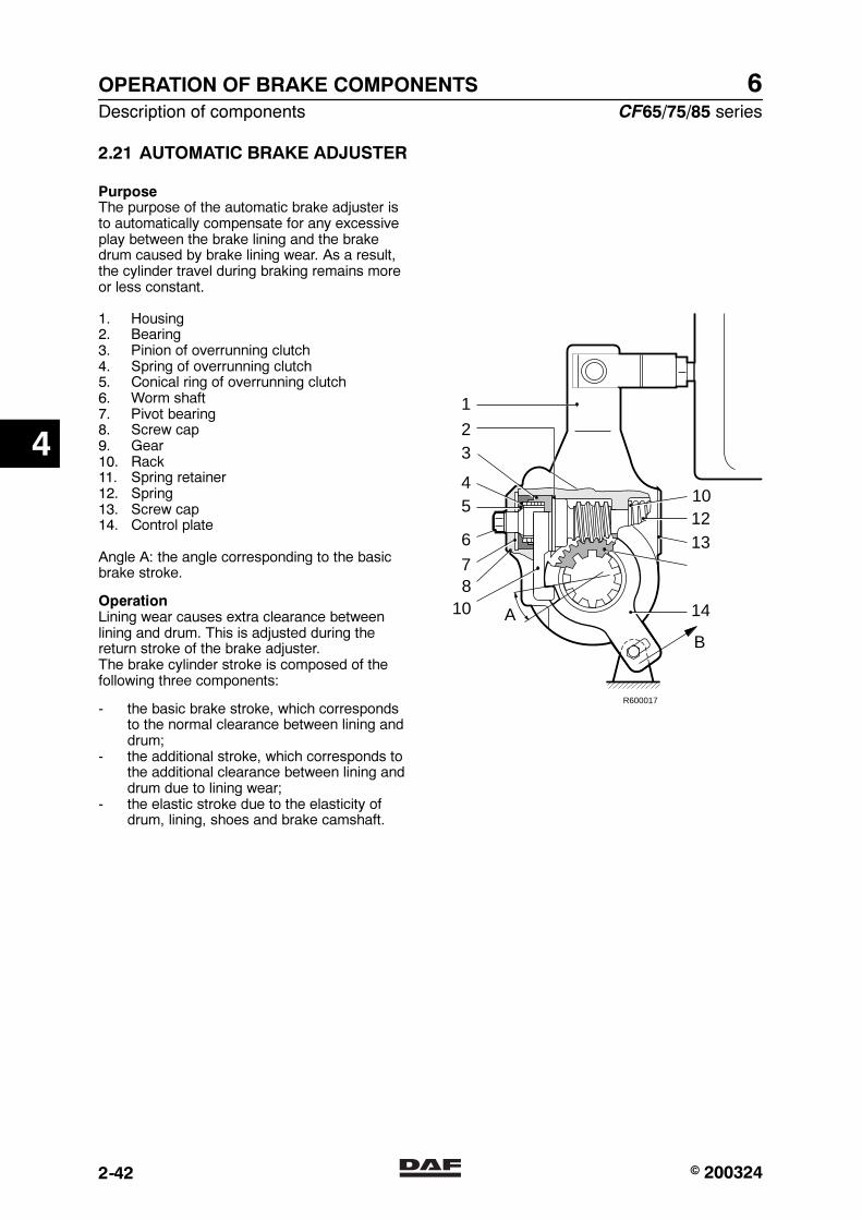
6OPERATION OF BRAKE COMPONENTS
Description of components CF65/75/85 series
2-42
2.21 AUTOMATIC BRAKE ADJUSTER
PurposeThe purpose of the automatic brake adjuster isto automatically compensate for any excessiveplay between the brake lining and the brakedrum caused by brake lining wear. As a result,the cylinder travel during braking remains moreor less constant.
1. Housing2. Bearing3. Pinion of overrunning clutch4. Spring of overrunning clutch5. Conical ring of overrunning clutch6. Worm shaft7. Pivot bearing8. Screw cap9. Gear10. Rack11. Spring retainer12. Spring13. Screw cap14. Control plate
Angle A: the angle corresponding to the basicbrake stroke.
OperationLining wear causes extra clearance betweenlining and drum. This is adjusted during thereturn stroke of the brake adjuster.The brake cylinder stroke is composed of thefollowing three components:
- the basic brake stroke, which correspondsto the normal clearance between lining anddrum;
- the additional stroke, which corresponds tothe additional clearance between lining anddrum due to lining wear;
- the elastic stroke due to the elasticity ofdrum, lining, shoes and brake camshaft.
1
23
45
6
78
10
101213
B
A 14
R600017
4
� 200324https://www.truck-manuals.net/
6
CF65/75/85 series Description of components
OPERATION OF BRAKE COMPONENTS
2-43
Basic brake strokeThe basic brake stroke is determined by thenotch in control plate 14, which is attached tothe axle housing. In the rest position, the rackshould rest against the upper edge of the notch.When the stroke exceeds angle A, the adjustingsystem is activated. Angle A corresponds to thenormal stroke.
Additional strokeIf the normal stroke is exceeded, the lower edgeof the notch of the control plate forces rack 10upwards. As a result, pinion 3 is turned.An overrunning clutch, consisting of spring 4and conical clutch 5, has been fitted betweenthe pinion and worm shaft 6, which permits freeturning in this direction.
During the return stroke, the rack is pulleddownwards by the upper edge of the notch. Thepinion now turns in the opposite direction, sothat the overrunning clutch drives worm shaft 6and the brake is adjusted.
Elastic strokeDuring the elastic part of the stroke, theconsiderable force transmitted pushes wormshaft 6 axially against spring 12. This will causethe worm shaft to become disengaged from theconical clutch.As a result, the conical clutch will be able to turnfreely over a certain distance during the returntravel, until clutch and worm shaft arere-engaged, without driving the worm shaft.From that moment, any rotation of the pinion willonce again adjust the length of stroke. As aresult of this construction, the elasticity of thecomponent involved will not be instrumental inadjusting the stroke.
4
� 200324https://www.truck-manuals.net/

6OPERATION OF BRAKE COMPONENTS
Description of components CF65/75/85 series
2-44
2.22 DISC BRAKE
VariantsThe disc brake construction consists of thebrake disc and the brake calliper. There are twovariants of this construction:
- Knorr SB7000, recognisable by the dividedhousing between the brake cylinder and thebrake pad holder and the rubber sleeve.
- Knorr SN7000, recognisable by theundivided housing between the brakecylinder and the brake pad holder and thesteel cap.
The Knorr SN7000 construction used on alldisc-brake front axles and on air-sprung rearaxles. On leaf-sprung rear axles the KnorrSB7000 construction is used. Operation of thetwo variants is identical. Only overhauling andthe parts of the brake calliper differ.
R600707
SB7000
SN7000
OperationBrakesThis disc brake works using a pneumatic brakechamber or spring brake cylinder.
If the brake is applied, the brake cylinder pushrod presses against the eccentrically mountedlever (1).Via bridge 2 and threaded bushes 3, the brakepad is pressed against the brake disc (4) at twopoints on the inside.Due to the reaction force (F2) at the eccentric,the floating brake saddle (5) will also press theopposite brake pad with the same force (F2).
45
1
3 2
R600486
4
� 200324https://www.truck-manuals.net/
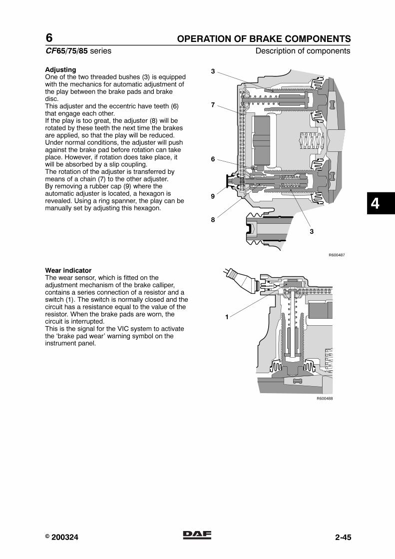
6
CF65/75/85 series Description of components
OPERATION OF BRAKE COMPONENTS
2-45
AdjustingOne of the two threaded bushes (3) is equippedwith the mechanics for automatic adjustment ofthe play between the brake pads and brakedisc.This adjuster and the eccentric have teeth (6)that engage each other.If the play is too great, the adjuster (8) will berotated by these teeth the next time the brakesare applied, so that the play will be reduced.Under normal conditions, the adjuster will pushagainst the brake pad before rotation can takeplace. However, if rotation does take place, itwill be absorbed by a slip coupling.The rotation of the adjuster is transferred bymeans of a chain (7) to the other adjuster.By removing a rubber cap (9) where theautomatic adjuster is located, a hexagon isrevealed. Using a ring spanner, the play can bemanually set by adjusting this hexagon.
R600487
3
7
6
8
3
9
Wear indicatorThe wear sensor, which is fitted on theadjustment mechanism of the brake calliper,contains a series connection of a resistor and aswitch (1). The switch is normally closed and thecircuit has a resistance equal to the value of theresistor. When the brake pads are worn, thecircuit is interrupted.This is the signal for the VIC system to activatethe ‘brake pad wear’ warning symbol on theinstrument panel.
1
R600488
4
� 200324https://www.truck-manuals.net/
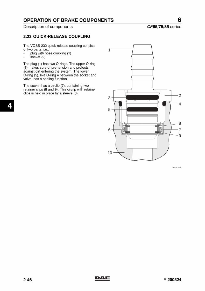
6OPERATION OF BRAKE COMPONENTS
Description of components CF65/75/85 series
2-46
2.23 QUICK-RELEASE COUPLING
The VOSS 232 quick-release coupling consistsof two parts, i.e.:- plug with hose coupling (1)- socket (2)
The plug (1) has two O-rings. The upper O-ring(3) makes sure of pre-tension and protectsagainst dirt entering the system. The lowerO-ring (5), like O-ring 4 between the socket andvalve, has a sealing function.
The socket has a circlip (7), containing tworetainer clips (8 and 9). This circlip with retainerclips is held in place by a sleeve (6).
R600365
2
1
3
5
6
10
4
8
79
4
� 200324https://www.truck-manuals.net/
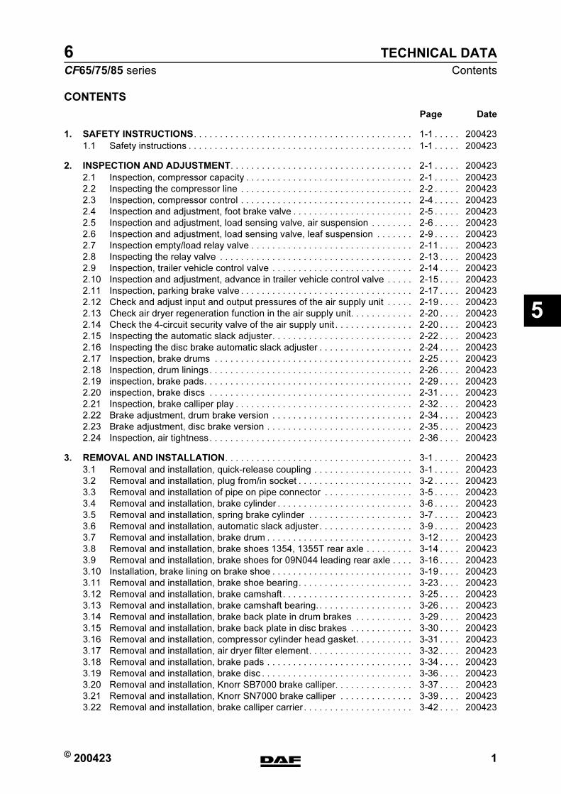
© 200423 1
Contents
TECHNICAL DATA
ΧΦ65/75/85 series
6
5
0 Technical data
CONTENTS
Page Date
1. SAFETY INSTRUCTIONS. . . . . . . . . . . . . . . . . . . . . . . . . . . . . . . . . . . . . . . . . . 1-1 . . . . . 200423
1.1 Safety instructions . . . . . . . . . . . . . . . . . . . . . . . . . . . . . . . . . . . . . . . . . . . 1-1 . . . . . 200423
2. INSPECTION AND ADJUSTMENT. . . . . . . . . . . . . . . . . . . . . . . . . . . . . . . . . . . 2-1 . . . . . 200423
2.1 Inspection, compressor capacity . . . . . . . . . . . . . . . . . . . . . . . . . . . . . . . . 2-1 . . . . . 200423
2.2 Inspecting the compressor line . . . . . . . . . . . . . . . . . . . . . . . . . . . . . . . . . 2-2 . . . . . 200423
2.3 Inspection, compressor control . . . . . . . . . . . . . . . . . . . . . . . . . . . . . . . . . 2-4 . . . . . 200423
2.4 Inspection and adjustment, foot brake valve . . . . . . . . . . . . . . . . . . . . . . . 2-5 . . . . . 200423
2.5 Inspection and adjustment, load sensing valve, air suspension . . . . . . . . 2-6 . . . . . 200423
2.6 Inspection and adjustment, load sensing valve, leaf suspension . . . . . . . 2-9 . . . . . 200423
2.7 Inspection empty/load relay valve . . . . . . . . . . . . . . . . . . . . . . . . . . . . . . . 2-11 . . . . 200423
2.8 Inspecting the relay valve . . . . . . . . . . . . . . . . . . . . . . . . . . . . . . . . . . . . . 2-13 . . . . 200423
2.9 Inspection, trailer vehicle control valve . . . . . . . . . . . . . . . . . . . . . . . . . . . 2-14 . . . . 200423
2.10 Inspection and adjustment, advance in trailer vehicle control valve . . . . . 2-15 . . . . 200423
2.11 Inspection, parking brake valve . . . . . . . . . . . . . . . . . . . . . . . . . . . . . . . . . 2-17 . . . . 200423
2.12 Check and adjust input and output pressures of the air supply unit . . . . . 2-19 . . . . 200423
2.13 Check air dryer regeneration function in the air supply unit. . . . . . . . . . . . 2-20 . . . . 200423
2.14 Check the 4-circuit security valve of the air supply unit . . . . . . . . . . . . . . . 2-20 . . . . 200423
2.15 Inspecting the automatic slack adjuster. . . . . . . . . . . . . . . . . . . . . . . . . . . 2-22 . . . . 200423
2.16 Inspecting the disc brake automatic slack adjuster . . . . . . . . . . . . . . . . . . 2-24 . . . . 200423
2.17 Inspection, brake drums . . . . . . . . . . . . . . . . . . . . . . . . . . . . . . . . . . . . . . 2-25 . . . . 200423
2.18 Inspection, drum linings. . . . . . . . . . . . . . . . . . . . . . . . . . . . . . . . . . . . . . . 2-26 . . . . 200423
2.19 inspection, brake pads. . . . . . . . . . . . . . . . . . . . . . . . . . . . . . . . . . . . . . . . 2-29 . . . . 200423
2.20 inspection, brake discs . . . . . . . . . . . . . . . . . . . . . . . . . . . . . . . . . . . . . . . 2-31 . . . . 200423
2.21 Inspection, brake calliper play . . . . . . . . . . . . . . . . . . . . . . . . . . . . . . . . . . 2-32 . . . . 200423
2.22 Brake adjustment, drum brake version . . . . . . . . . . . . . . . . . . . . . . . . . . . 2-34 . . . . 200423
2.23 Brake adjustment, disc brake version . . . . . . . . . . . . . . . . . . . . . . . . . . . . 2-35 . . . . 200423
2.24 Inspection, air tightness. . . . . . . . . . . . . . . . . . . . . . . . . . . . . . . . . . . . . . . 2-36 . . . . 200423
3. REMOVAL AND INSTALLATION. . . . . . . . . . . . . . . . . . . . . . . . . . . . . . . . . . . . 3-1 . . . . . 200423
3.1 Removal and installation, quick-release coupling . . . . . . . . . . . . . . . . . . . 3-1 . . . . . 200423
3.2 Removal and installation, plug from/in socket . . . . . . . . . . . . . . . . . . . . . . 3-2 . . . . . 200423
3.3 Removal and installation of pipe on pipe connector . . . . . . . . . . . . . . . . . 3-5 . . . . . 200423
3.4 Removal and installation, brake cylinder . . . . . . . . . . . . . . . . . . . . . . . . . . 3-6 . . . . . 200423
3.5 Removal and installation, spring brake cylinder . . . . . . . . . . . . . . . . . . . . 3-7 . . . . . 200423
3.6 Removal and installation, automatic slack adjuster . . . . . . . . . . . . . . . . . . 3-9 . . . . . 200423
3.7 Removal and installation, brake drum . . . . . . . . . . . . . . . . . . . . . . . . . . . . 3-12 . . . . 200423
3.8 Removal and installation, brake shoes 1354, 1355T rear axle . . . . . . . . . 3-14 . . . . 200423
3.9 Removal and installation, brake shoes for 09N044 leading rear axle . . . . 3-16 . . . . 200423
3.10 Installation, brake lining on brake shoe . . . . . . . . . . . . . . . . . . . . . . . . . . . 3-19 . . . . 200423
3.11 Removal and installation, brake shoe bearing. . . . . . . . . . . . . . . . . . . . . . 3-23 . . . . 200423
3.12 Removal and installation, brake camshaft . . . . . . . . . . . . . . . . . . . . . . . . . 3-25 . . . . 200423
3.13 Removal and installation, brake camshaft bearing. . . . . . . . . . . . . . . . . . . 3-26 . . . . 200423
3.14 Removal and installation, brake back plate in drum brakes . . . . . . . . . . . 3-29 . . . . 200423
3.15 Removal and installation, brake back plate in disc brakes . . . . . . . . . . . . 3-30 . . . . 200423
3.16 Removal and installation, compressor cylinder head gasket. . . . . . . . . . . 3-31 . . . . 200423
3.17 Removal and installation, air dryer filter element. . . . . . . . . . . . . . . . . . . . 3-32 . . . . 200423
3.18 Removal and installation, brake pads . . . . . . . . . . . . . . . . . . . . . . . . . . . . 3-34 . . . . 200423
3.19 Removal and installation, brake disc . . . . . . . . . . . . . . . . . . . . . . . . . . . . . 3-36 . . . . 200423
3.20 Removal and installation, Knorr SB7000 brake calliper. . . . . . . . . . . . . . . 3-37 . . . . 200423
3.21 Removal and installation, Knorr SN7000 brake calliper . . . . . . . . . . . . . . 3-39 . . . . 200423
3.22 Removal and installation, brake calliper carrier . . . . . . . . . . . . . . . . . . . . . 3-42 . . . . 200423
https://www.truck-manuals.net/

TECHNICAL DATA
2 © 200423
Contents
5
ΧΦ65/75/85 series
6
3.23 Removing and installing bellows with
Knorr SB7000 brake calliper thrust piece . . . . . . . . . . . . . . . . . . . . . . . . . 3-43 . . . . 200423
3.24 Removing and installing bellows with
Knorr SN7000 brake calliper thrust piece . . . . . . . . . . . . . . . . . . . . . . . . . 3-45 . . . . 200423
3.25 Removing and installing bronze bearing bush of
Knorr SB7000 brake calliper . . . . . . . . . . . . . . . . . . . . . . . . . . . . . . . . . . . 3-50 . . . . 200423
3.26 Removing and installing bronze bearing bush of
Knorr SN7000 brake calliper . . . . . . . . . . . . . . . . . . . . . . . . . . . . . . . . . . . 3-52 . . . . 200423
3.27 Removing and installing rubber bearing bush of
Knorr SB7000 brake calliper . . . . . . . . . . . . . . . . . . . . . . . . . . . . . . . . . . . 3-55 . . . . 200423
3.28 Removing and installing rubber bearing bush of
Knorr SN7000 brake calliper . . . . . . . . . . . . . . . . . . . . . . . . . . . . . . . . . . . 3-56 . . . . 200423
3.29 Removing and installing bellows of bronze bearing bush of
Knorr SB7000 brake calliper . . . . . . . . . . . . . . . . . . . . . . . . . . . . . . . . . . . 3-58 . . . . 200423
3.30 Removing and installing bellows of bronze bearing bush of
Knorr SN7000 brake calliper . . . . . . . . . . . . . . . . . . . . . . . . . . . . . . . . . . . 3-60 . . . . 200423
4. DISASSEMBLY AND ASSEMBLY . . . . . . . . . . . . . . . . . . . . . . . . . . . . . . . . . . . 4-1 . . . . . 200423
4.1 Disassembly and assembly, brake chamber . . . . . . . . . . . . . . . . . . . . . . . 4-1 . . . . . 200423
4.2 Disassembly and assembly, Wabco spring brake cylinder . . . . . . . . . . . . 4-2 . . . . . 200423
Page Date
https://www.truck-manuals.net/
© 200423 1-1
Safety instructions
BRAKE SYSTEM AND COMPONENTS
ΧΦ65/75/85 series
6
5
1. SAFETY INSTRUCTIONS
1.1 SAFETY INSTRUCTIONS
Always observe the local safety and environmental regulations.
If the parking brake is deactivated when working on the vehicle, place chocks in front of and behind the wheels to prevent the vehicle from moving.
The substances and auxiliary substances (to be) used may constitute a direct or indirect health hazard. For that reason, always wear protective clothing and protective equipment (e.g. goggles, gloves) to prevent inhalation, skin contact, etc.
Use only the specified special tools.
Parts of threaded connections have to be clean and free of lubricants before use
Check the correct operation of the vehicle, and the brake system in particular if work has been carried out on it, before handing over the vehicle to the user
}
}
}
}
}
}
https://www.truck-manuals.net/
BRAKE SYSTEM AND COMPONENTS
1-2 © 200423
Safety instructions
5
ΧΦ65/75/85 series
6
https://www.truck-manuals.net/
© 200423 2-1
Inspection and adjustment
BRAKE SYSTEM AND COMPONENTS
ΧΦ65/75/85 series
6
5
2. INSPECTION AND ADJUSTMENT
2.1 INSPECTION, COMPRESSOR CAPACITY
1. Bring the engine up to operating temperature.
2. For a vehicle with air suspension, the chassis should be at the normal driving height.
3. Put chocks in front of and behind the rear-axle wheels to prevent the vehicle from moving.
4. Position the parking brake in the driving position.
Note:If, when draining the air reservoirs, they appear to hold an excessive quantity of oil, check the condition of the compressor and check the compressor for the presence of carbon deposits in the compressor pipes.
5. Bleed the entire brake system.
6. The capacity test requires that a completely empty system should be at operating pressure within 5 minutes, at an engine speed of 0.6 x maximum engine speed.
https://www.truck-manuals.net/

BRAKE SYSTEM AND COMPONENTS
2-2 © 200423
Inspection and adjustment
5
ΧΦ65/75/85 series
6
2.2 INSPECTING THE COMPRESSOR LINE
Remain at a safe distance from rotating and/or moving components.
Note:If excessive values are measured, the inside of the air-dryer housing and the silencer on the bleed vent should first be cleaned. Then repeat the inspection.
1. Bring the engine up to operating temperature.
2. Bleed the system to a pressure below the cut-in pressure of the pressure regulator.
3. Remove the compressor control pipe (1) which is connected to connection point (23) of the air dryer. Then seal the opening at connection point (23).
4. Build up pressure in the brake system (pressure regulator must cut out).
5. When the engine is not running, remove the safety valve from the compressor pipe and replace it with a test nipple.
6. Connect a pressure gauge (measuring range 0 - 16 bar) to the test nipple.
7. Start the engine and run it at maximum engine speed.
8. The pressure gauge should indicate a pressure below 2 bar with the pressure regulator switched off. If the measured pressure exceeds the value indicated, the compressor line should be cleaned or replaced.
Note:If the pressure measured is too high, this indicates that there are excessive carbon deposits in the compressor pipe. The cause could be poor condition of the compressor (oil consumption).
}
R600521
1
R600249
https://www.truck-manuals.net/
© 200423 2-3
Inspection and adjustment
BRAKE SYSTEM AND COMPONENTS
ΧΦ65/75/85 series
6
5
9. Run the engine at idling speed.
10. Bleed the brake system until the cut-in pressure of the pressure regulator has been reached and switch off the engine. The indicator on the pressure gauge should not drop rapidly. If necessary, check the system for leaks. Pay special attention to the compressor line and the compressor.
11. Fit the safety valve.
12. Fit the compressor control pipe to connection point (23) of the air dryer.
https://www.truck-manuals.net/
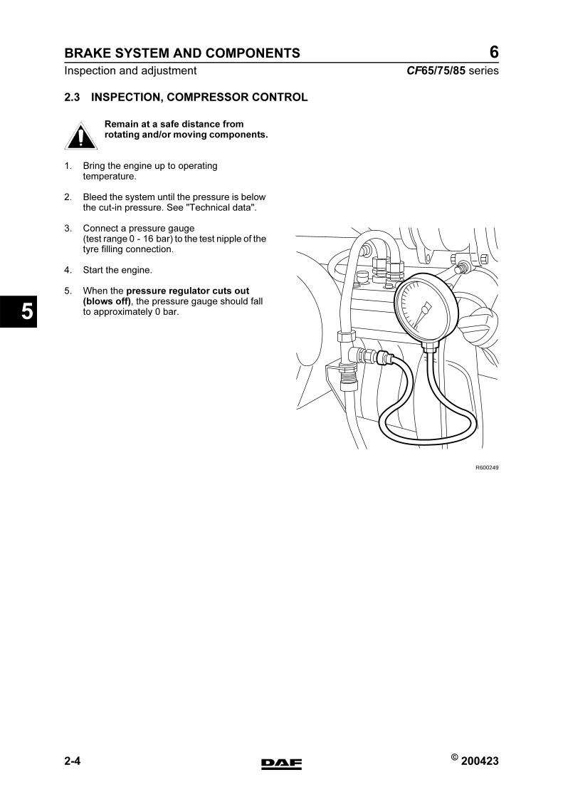
BRAKE SYSTEM AND COMPONENTS
2-4 © 200423
Inspection and adjustment
5
ΧΦ65/75/85 series
6
2.3 INSPECTION, COMPRESSOR CONTROL
Remain at a safe distance from rotating and/or moving components.
1. Bring the engine up to operating temperature.
2. Bleed the system until the pressure is below the cut-in pressure. See "Technical data".
3. Connect a pressure gauge(test range 0 - 16 bar) to the test nipple of the tyre filling connection.
4. Start the engine.
5. When the pressure regulator cuts out (blows off), the pressure gauge should fall to approximately 0 bar.
}
R600249
https://www.truck-manuals.net/
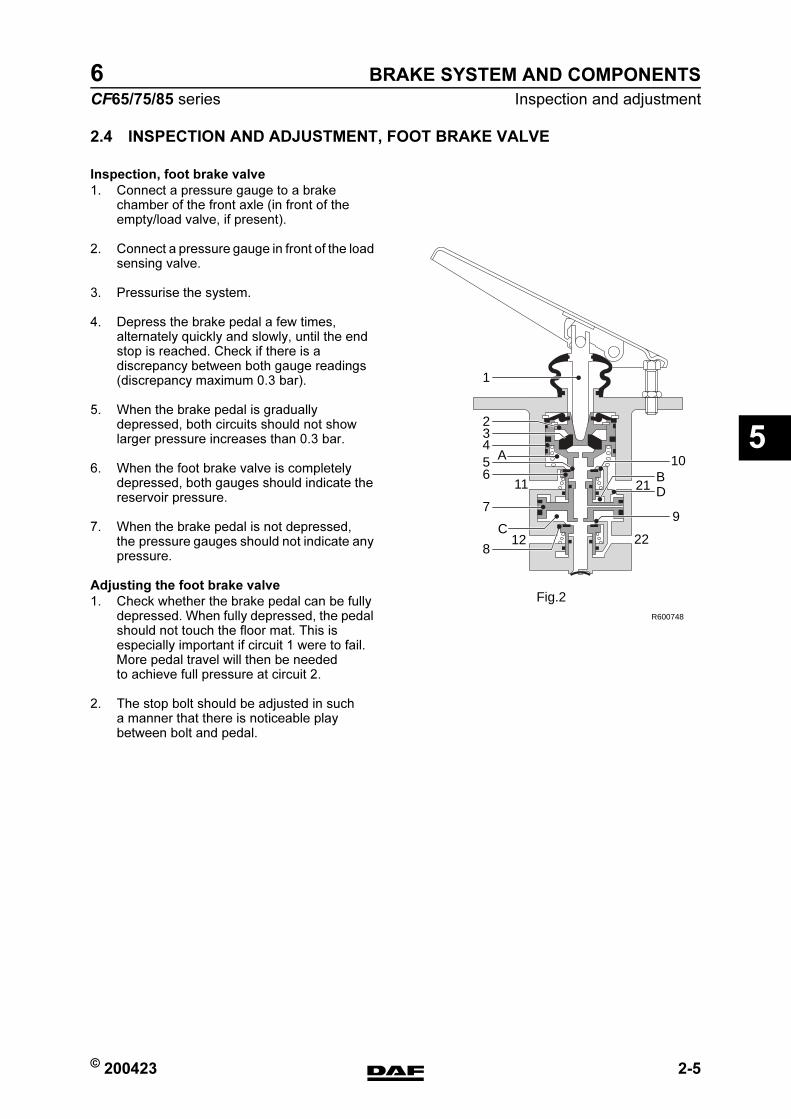
© 200423 2-5
Inspection and adjustment
BRAKE SYSTEM AND COMPONENTS
ΧΦ65/75/85 series
6
5
2.4 INSPECTION AND ADJUSTMENT, FOOT BRAKE VALVE
Inspection, foot brake valve
1. Connect a pressure gauge to a brake chamber of the front axle (in front of the empty/load valve, if present).
2. Connect a pressure gauge in front of the load sensing valve.
3. Pressurise the system.
4. Depress the brake pedal a few times, alternately quickly and slowly, until the end stop is reached. Check if there is a discrepancy between both gauge readings (discrepancy maximum 0.3 bar).
5. When the brake pedal is gradually depressed, both circuits should not show larger pressure increases than 0.3 bar.
6. When the foot brake valve is completely depressed, both gauges should indicate the reservoir pressure.
7. When the brake pedal is not depressed, the pressure gauges should not indicate any pressure.
Adjusting the foot brake valve
1. Check whether the brake pedal can be fully depressed. When fully depressed, the pedal should not touch the floor mat. This is especially important if circuit 1 were to fail. More pedal travel will then be needed to achieve full pressure at circuit 2.
2. The stop bolt should be adjusted in such a manner that there is noticeable play between bolt and pedal.
21
2212
A
BD
C
10
97
8
65432
1
11
R600748
Fig.2
https://www.truck-manuals.net/

BRAKE SYSTEM AND COMPONENTS
2-6 © 200423
Inspection and adjustment
5
ΧΦ65/75/85 series
6
2.5 INSPECTION AND ADJUSTMENT, LOAD SENSING VALVE,
AIR SUSPENSION
Explanatory notes on instruction plate
This plate is mounted on the rear door pillar on the left-hand side of the vehicle. The information on the instruction plate relates to the axle loads, the delivery pressures and bellows pressures, following the sequence of the axles beneath the vehicle.
Therefore, "1" refers to the (first) front axle, "2" to the next following axle, etc.If the vehicle is fitted with a relay valve in the front axle brake circuit, the box beneath the valve illustration will be blank. Throughout the column, a value of 8.1 bar has been filled in for "delivery pressure p2" under axle "1".If the vehicle is equipped with a control valve instead of the relay valve mentioned, the box will contain a pressure ratio, e.g."i = 1 : 1,5". The "delivery pressure p2" of axle "1" then indicates variable readings.These values can be used to check the brake pressure values of the front axle and to carry out the inspection/adjustment below at the same time. To do this, connect a pressure gauge to the test connection of one of the front axle brake cylinders.
AUTOM. LASTAFHANKELIJKE REMKRACHTREGELINGAUTOM. LOAD SENSING DEVICEAUTOM. LASTABHAENGIGE BREMSKRAFT REGELEINR.DISPOSITIF DE CORRECTION AUTOM. DE FREINAGEREGOLATORE AUTOM. DELLA FORZA FRENANTEREGULADOR AUTOM. DEL ESFUERZO DE FRENANDA
TYPE - TIPO : FA
1425289
2 1.8
2.5
4.0
5.0
6.0
10.0
11.5
13.0
2 2.0
2.1
2.8
3.5
4.3
7.3
8.3
8.3
31 5.7
5.8
6.0
6.3
6.6
7.7
8.1
8.1
12 0.2
0.5
1.3
1.8
2.3
4.2
4.9
5.6
1
AS
LAS
T
G
AX
LE L
OA
DA
CH
SLA
ST
CH
AR
GE
SO
US
ES
SIE
UC
AR
ICO
AS
SE
CA
RG
A E
JE
x104
N
UIT
GES
TUU
RD
E D
RU
K
p2D
ELIV
ERY
PR
ESS
UR
EA
US
GES
TEU
ERTE
R D
RU
CK
PRES
SIO
N D
ELIV
REE
PRES
SIO
NE
US
CIT
APR
ESIO
N D
E S
ALI
DA
b
ar
BA
LG D
RU
K
p43
PRES
SU
RE
BEL
LOW
SB
ALG
DR
UC
KPR
ESS
ION
CO
US
SIN
PRES
S. C
US
CIN
I AR
IAPR
ESIO
N F
UEL
LES
bar
±0.4
±0.2
W47
5 72
1 00
3 0
1 =
1 :
1.5
MEE
REG
ELV
ENTI
ELEM
PTY-
LOA
D V
ALV
ELA
ST-
LEER
VEN
TIEL
VA
LVE
CH
AR
GE-
VID
EVA
LVO
LA V
UO
TO-C
AR
ICO
VALV
ULA
VA
CIO
-CA
RG
A
p1 =
> 8
.5 b
arp4
= 8
.0 b
ar
p1 p2
p4p4
3
R600472
https://www.truck-manuals.net/
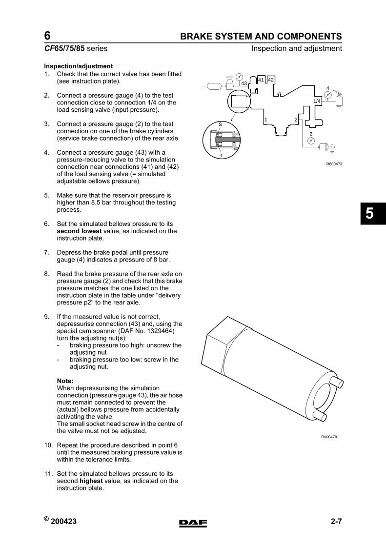
© 200423 2-7
Inspection and adjustment
BRAKE SYSTEM AND COMPONENTS
ΧΦ65/75/85 series
6
5
Inspection/adjustment
1. Check that the correct valve has been fitted (see instruction plate).
2. Connect a pressure gauge (4) to the test connection close to connection 1/4 on the load sensing valve (input pressure).
3. Connect a pressure gauge (2) to the test connection on one of the brake cylinders (service brake connection) of the rear axle.
4. Connect a pressure gauge (43) with a pressure-reducing valve to the simulation connection near connections (41) and (42) of the load sensing valve (= simulated adjustable bellows pressure).
5. Make sure that the reservoir pressure is higher than 8.5 bar throughout the testing process.
6. Set the simulated bellows pressure to its second lowest value, as indicated on the instruction plate.
7. Depress the brake pedal until pressure gauge (4) indicates a pressure of 8 bar.
8. Read the brake pressure of the rear axle on pressure gauge (2) and check that this brake pressure matches the one listed on the instruction plate in the table under "delivery pressure p2" to the rear axle.
9. If the measured value is not correct, depressurise connection (43) and, using the special cam spanner (DAF No. 1329464) turn the adjusting nut(s):- braking pressure too high: unscrew the
adjusting nut- braking pressure too low: screw in the
adjusting nut.
Note:When depressurising the simulation connection (pressure gauge 43), the air hose must remain connected to prevent the (actual) bellows pressure from accidentally activating the valve.The small socket head screw in the centre of the valve must not be adjusted.
10. Repeat the procedure described in point 6 until the measured braking pressure value is within the tolerance limits.
11. Set the simulated bellows pressure to its second highest value, as indicated on the instruction plate.
43
1/4
4
2
2
R600473
1
41 42
r
s
R600478
https://www.truck-manuals.net/

BRAKE SYSTEM AND COMPONENTS
2-8 © 200423
Inspection and adjustment
5
ΧΦ65/75/85 series
6
12. Depress the brake pedal until pressure gauge (4) indicates a pressure of 8 bar.
13. Read the pressure gauge (2) and check that this braking pressure matches the pressure indicated in the table on the instruction plate.
14. If the measured reading is not correct, depressurise connection (43) and turn the adjusting bolt (r) using a Torx screwdriver:- braking pressure too high: screw in the
adjusting bolt- braking pressure too low: unscrew the
adjusting bolt.
Note:When depressurising the simulation connection (pressure gauge 43), the air hose must remain connected to prevent the (actual) bellows pressure from accidentally activating the valve.The small socket head screw in the centre of the valve must not be adjusted.
15. If the adjusting bolt (r) has been turned, repeat the procedure from point 6.
https://www.truck-manuals.net/
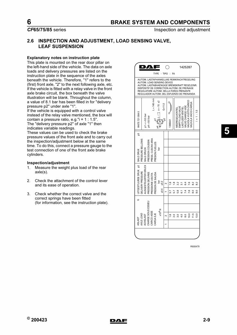
© 200423 2-9
Inspection and adjustment
BRAKE SYSTEM AND COMPONENTS
ΧΦ65/75/85 series
6
5
2.6 INSPECTION AND ADJUSTMENT, LOAD SENSING VALVE,
LEAF SUSPENSION
Explanatory notes on instruction plate
This plate is mounted on the rear door pillar on the left-hand side of the vehicle. The data on axle loads and delivery pressures are listed on the instruction plate in the sequence of the axles beneath the vehicle. Therefore, "1" refers to the (first) front axle, "2" to the next following axle, etc.If the vehicle is fitted with a relay valve in the front axle brake circuit, the box beneath the valve illustration will be blank. Throughout the column, a value of 8.1 bar has been filled in for "delivery pressure p2" under axle "1".If the vehicle is equipped with a control valve instead of the relay valve mentioned, the box will contain a pressure ratio, e.g."i = 1 : 1.5". The "delivery pressure p2" of axle "1" then indicates variable readings.These values can be used to check the brake pressure values of the front axle and to carry out the inspection/adjustment below at the same time. To do this, connect a pressure gauge to the test connection of one of the front axle brake cylinders.
Inspection/adjustment
1. Measure the weight plus load of the rear axle(s).
2. Check the attachment of the control lever and its ease of operation.
3. Check whether the correct valve and the correct springs have been fitted (for information, see the instruction plate).
AUTOM. LASTAFHANKELIJKE REMKRACHTREGELINGAUTOM. LOAD SENSING DEVICEAUTOM. LASTABHAENGIGE BREMSKRAFT REGELEINR.DISPOSITIF DE CORRECTION AUTOM. DE FREINAGEREGOLATORE AUTOM. DELLA FORZA FRENANTEREGULADOR AUTOM. DEL ESFUERZO DE FRENANDA
TYPE - TIPO : FA
1425287
2 1.8
2.0
3.0
4.0
8.0
10.0
11.5
13.0
2 1.8
1.8
2.2
3.1
6.4
7.6
8.2
8.2
1 5.7
5.7
5.8
6.1
7.4
7.8
8.0
8.0
1AS
LAS
T
G
AX
LE L
OA
DA
CH
SLA
ST
CH
AR
GE
SO
US
ES
SIE
UC
AR
ICO
AS
SE
CA
RG
A E
JE
x104
N
UIT
GES
TUU
RD
E D
RU
K
p2D
ELIV
ERY
PR
ESS
UR
EA
US
GES
TEU
ERTE
R D
RU
CK
PRES
SIO
N D
ELIV
REE
PRES
SIO
NE
US
CIT
APR
ESIO
N D
E S
ALI
DA
b
ar
BA
LG D
RU
K
p3PR
ESS
UR
E B
ELLO
WS
BA
LG D
RU
CK
PRES
SIO
N C
OU
SS
INPR
ESS
. CU
SC
INI A
RIA
PRES
ION
FU
ELLE
S
ba
r±0
.4±0
.2
W47
5 72
1 00
4 0
1396
041
i =
1 :
1.5
MEE
REG
ELV
ENTI
ELEM
PTY-
LOA
D V
ALV
ELA
ST-
LEER
VEN
TIEL
VA
LVE
CH
AR
GE-
VID
EVA
LVO
LA V
UO
TO-C
AR
ICO
VALV
ULA
VA
CIO
-CA
RG
A
p1 =
> 8
.5 b
arp4
= 8
.0 b
ar
L =
140
mm
a =
15 ±
2
G=1
1.0
Lp1 p2
p4
R600479
https://www.truck-manuals.net/
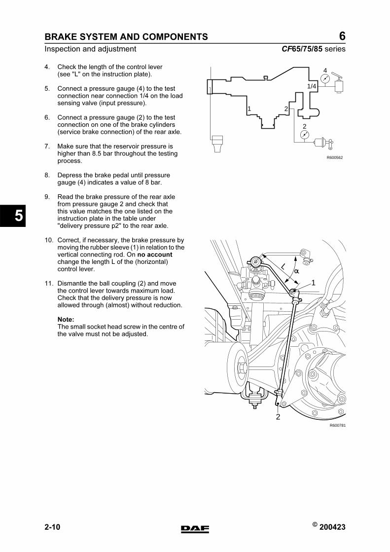
BRAKE SYSTEM AND COMPONENTS
2-10 © 200423
Inspection and adjustment
5
ΧΦ65/75/85 series
6
4. Check the length of the control lever (see "L" on the instruction plate).
5. Connect a pressure gauge (4) to the test connection near connection 1/4 on the load sensing valve (input pressure).
6. Connect a pressure gauge (2) to the test connection on one of the brake cylinders (service brake connection) of the rear axle.
7. Make sure that the reservoir pressure is higher than 8.5 bar throughout the testing process.
8. Depress the brake pedal until pressure gauge (4) indicates a value of 8 bar.
9. Read the brake pressure of the rear axle from pressure gauge 2 and check that this value matches the one listed on the instruction plate in the table under "delivery pressure p2" to the rear axle.
10. Correct, if necessary, the brake pressure by moving the rubber sleeve (1) in relation to the vertical connecting rod. On no account change the length L of the (horizontal) control lever.
11. Dismantle the ball coupling (2) and move the control lever towards maximum load. Check that the delivery pressure is now allowed through (almost) without reduction.
Note:The small socket head screw in the centre of the valve must not be adjusted.
1/4
4
2
2
R600562
1
L
R600781
1
2
https://www.truck-manuals.net/

© 200423 2-11
Inspection and adjustment
BRAKE SYSTEM AND COMPONENTS
ΧΦ65/75/85 series
6
5
2.7 INSPECTION EMPTY/LOAD RELAY VALVE
1. Using a T-piece, connect a pressure gauge to connecting point (41).
2. Connect a pressure gauge to the test connection on one of the brake chambers of the front axle.
3. Connect a pressure gauge to the test connection on one of the brake chambers of the rear axle.
4. Pressurise the system.
Testing when empty
1. Set the load sensing valve to the empty position.
2. Slowly depress the brake pedal.The pressure on the front axle should rise gradually, not in jumps.The pressure on the front axle will rise less quickly than that on connecting point (41). (With an empty vehicle, the difference will be greater than with a partially loaded vehicle).
1 2
3
4241
R600904
4 6
5
1 2
3
4241
R600905
https://www.truck-manuals.net/

BRAKE SYSTEM AND COMPONENTS
2-12 © 200423
Inspection and adjustment
5
ΧΦ65/75/85 series
6
Testing when fully loaded
1. Set the load sensing valve to the full-load position.
2. Slowly depress the brake pedal.The pressure on the front axle should rise gradually, not in jumps.The pressure on the front axle will rise as quickly (approx. 0.2 bar) as that on connection point (41). It must be possible to approximate the system pressure.
Inspection when faulty
1. Disconnect the pipe to connecting point (42) and plug off the pipe.
2. Repeat point 8.
3. Set the load sensing valve as specified.
4. Reconnect the pipes to points (41) and (42) in the original manner.
5. Remove the pressure gauges.
Inspection, output pressure to the front axle
1. Measure the rear axle load.
2. Check the load sensing valve setting.
3. Connect a pressure gauge to the test connection for the load sensing valve (input pressure) and a pressure gauge to the test connection on the brake cylinder of the front axle.
4. Make sure that the reservoir pressure exceeds 6.5 bar.
5. Depress the brake pedal until the pressure gauge on the test connection of the load sensing valve reads 6 bar, and read off the braking pressure on the pressure gauge of the front axle.
6. Compare this value with the data in the table attached to the door pillar.
00,10,25
1
1
2
2
3
3
4
4
5
5
6
6
7
7
8
8
9
9
10
10
+_
R600906
P 042 =
P42 P41=
00,10,5
1
1
2
2
3
3
4
4
5
5
6
6
7
7
8
8
9
9
10
10
P 042 =
P42 P41=
1:2,7
1:1,5
41(bar)p
2(ba
r)p
R600745
https://www.truck-manuals.net/
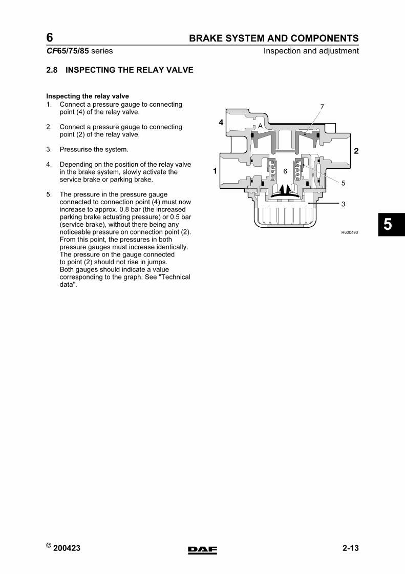
© 200423 2-13
Inspection and adjustment
BRAKE SYSTEM AND COMPONENTS
ΧΦ65/75/85 series
6
5
2.8 INSPECTING THE RELAY VALVE
Inspecting the relay valve
1. Connect a pressure gauge to connecting point (4) of the relay valve.
2. Connect a pressure gauge to connecting point (2) of the relay valve.
3. Pressurise the system.
4. Depending on the position of the relay valve in the brake system, slowly activate the service brake or parking brake.
5. The pressure in the pressure gauge connected to connection point (4) must now increase to approx. 0.8 bar (the increased parking brake actuating pressure) or 0.5 bar (service brake), without there being any noticeable pressure on connection point (2). From this point, the pressures in both pressure gauges must increase identically. The pressure on the gauge connected to point (2) should not rise in jumps. Both gauges should indicate a value corresponding to the graph. See "Technical data".
R600490
2
1 6
4 A
5
3
7
https://www.truck-manuals.net/
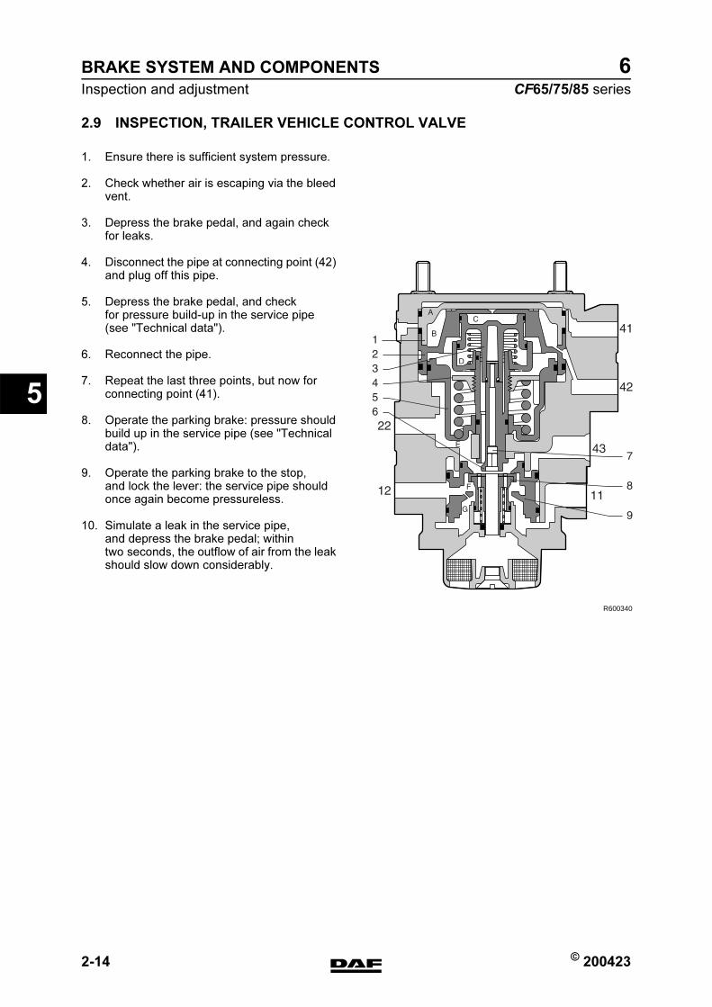
BRAKE SYSTEM AND COMPONENTS
2-14 © 200423
Inspection and adjustment
5
ΧΦ65/75/85 series
6
2.9 INSPECTION, TRAILER VEHICLE CONTROL VALVE
1. Ensure there is sufficient system pressure.
2. Check whether air is escaping via the bleed vent.
3. Depress the brake pedal, and again check for leaks.
4. Disconnect the pipe at connecting point (42) and plug off this pipe.
5. Depress the brake pedal, and check for pressure build-up in the service pipe (see "Technical data").
6. Reconnect the pipe.
7. Repeat the last three points, but now for connecting point (41).
8. Operate the parking brake: pressure should build up in the service pipe (see "Technical data").
9. Operate the parking brake to the stop, and lock the lever: the service pipe should once again become pressureless.
10. Simulate a leak in the service pipe, and depress the brake pedal; within two seconds, the outflow of air from the leak should slow down considerably.
R600340
https://www.truck-manuals.net/
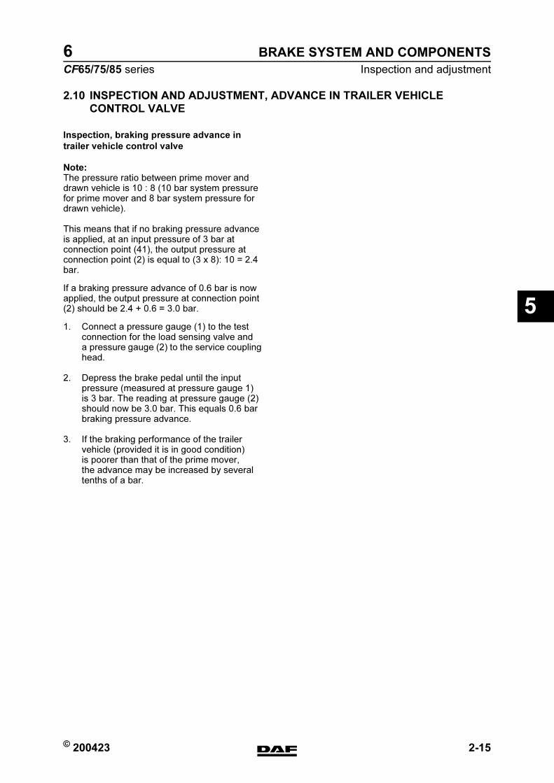
© 200423 2-15
Inspection and adjustment
BRAKE SYSTEM AND COMPONENTS
ΧΦ65/75/85 series
6
5
2.10 INSPECTION AND ADJUSTMENT, ADVANCE IN TRAILER VEHICLE
CONTROL VALVE
Inspection, braking pressure advance in
trailer vehicle control valve
Note:The pressure ratio between prime mover and drawn vehicle is 10 : 8 (10 bar system pressure for prime mover and 8 bar system pressure for drawn vehicle).
This means that if no braking pressure advance is applied, at an input pressure of 3 bar at connection point (41), the output pressure at connection point (2) is equal to (3 x 8): 10 = 2.4 bar.
If a braking pressure advance of 0.6 bar is now applied, the output pressure at connection point (2) should be 2.4 + 0.6 = 3.0 bar.
1. Connect a pressure gauge (1) to the test connection for the load sensing valve and a pressure gauge (2) to the service coupling head.
2. Depress the brake pedal until the input pressure (measured at pressure gauge 1) is 3 bar. The reading at pressure gauge (2) should now be 3.0 bar. This equals 0.6 bar braking pressure advance.
3. If the braking performance of the trailer vehicle (provided it is in good condition) is poorer than that of the prime mover, the advance may be increased by several tenths of a bar.
https://www.truck-manuals.net/
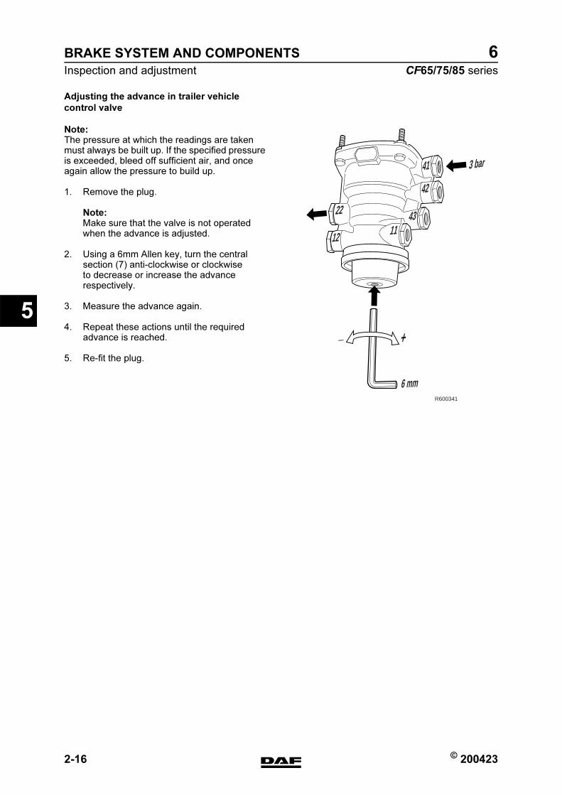
BRAKE SYSTEM AND COMPONENTS
2-16 © 200423
Inspection and adjustment
5
ΧΦ65/75/85 series
6
Adjusting the advance in trailer vehicle
control valve
Note:The pressure at which the readings are taken must always be built up. If the specified pressure is exceeded, bleed off sufficient air, and once again allow the pressure to build up.
1. Remove the plug.
Note:Make sure that the valve is not operated when the advance is adjusted.
2. Using a 6mm Allen key, turn the central section (7) anti-clockwise or clockwise to decrease or increase the advance respectively.
3. Measure the advance again.
4. Repeat these actions until the required advance is reached.
5. Re-fit the plug.
41
42
3 bar
6 mm
4311
12
+_
22
R600341
https://www.truck-manuals.net/

© 200423 2-17
Inspection and adjustment
BRAKE SYSTEM AND COMPONENTS
ΧΦ65/75/85 series
6
5
2.11 INSPECTION, PARKING BRAKE VALVE
Parking brake valve with trailer control and test position
1. Ensure there is sufficient system pressure.
2. Connect pressure gauges to connection point (43) of the trailer control valve and to connection point (12) of a spring brake cylinder.
Inspecting the driving position
1. Place the parking brake valve in the driving position. Both pressure gauges must now indicate a pressure of approx. 8.5 bar. This is the limiting pressure of the pressure limiting valve.
Inspecting the emergency brake
1. Move the parking brake valve slowly towards the parking position. Both pressure gauges should now gradually fall to 0 bar (with the exception of the first 10 angular displacement. See graph in "Technical data").
Inspecting the parking position
1. In the parking position, both pressure gauges should read 0 bar.
Inspecting the test position
1. Place the parking brake valve in the parking position, depress the handle, and move it to the test position. The pressure gauge at connection point (43) of the trailer vehicle control valve should read approx. 8.5 bar. The pressure gauge on the connection point of the spring brake cylinder should read 0 bar.
3211 22
a
23
5
4
6
8
7
9
10
R600092
https://www.truck-manuals.net/
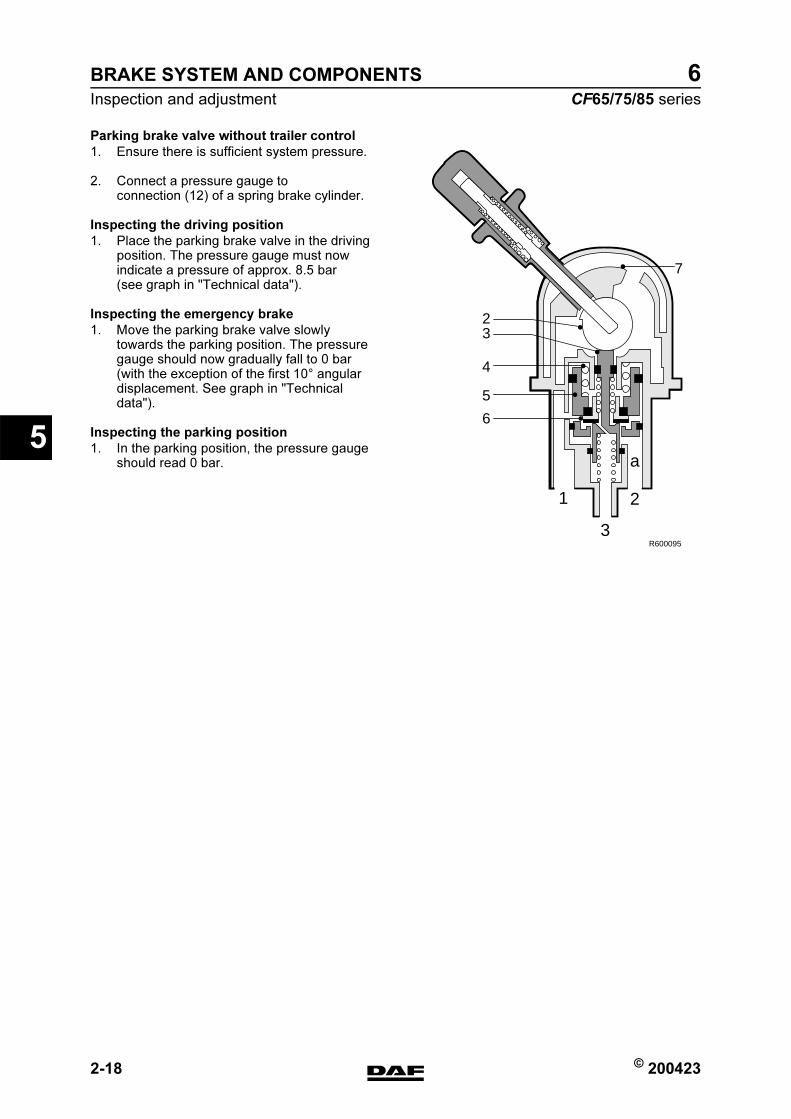
BRAKE SYSTEM AND COMPONENTS
2-18 © 200423
Inspection and adjustment
5
ΧΦ65/75/85 series
6
Parking brake valve without trailer control
1. Ensure there is sufficient system pressure.
2. Connect a pressure gauge to connection (12) of a spring brake cylinder.
Inspecting the driving position
1. Place the parking brake valve in the driving position. The pressure gauge must now indicate a pressure of approx. 8.5 bar (see graph in "Technical data").
Inspecting the emergency brake
1. Move the parking brake valve slowly towards the parking position. The pressure gauge should now gradually fall to 0 bar (with the exception of the first 10 angular displacement. See graph in "Technical data").
Inspecting the parking position
1. In the parking position, the pressure gauge should read 0 bar.
R600095
2
7
3
4
5
6
1
3
2
a
https://www.truck-manuals.net/
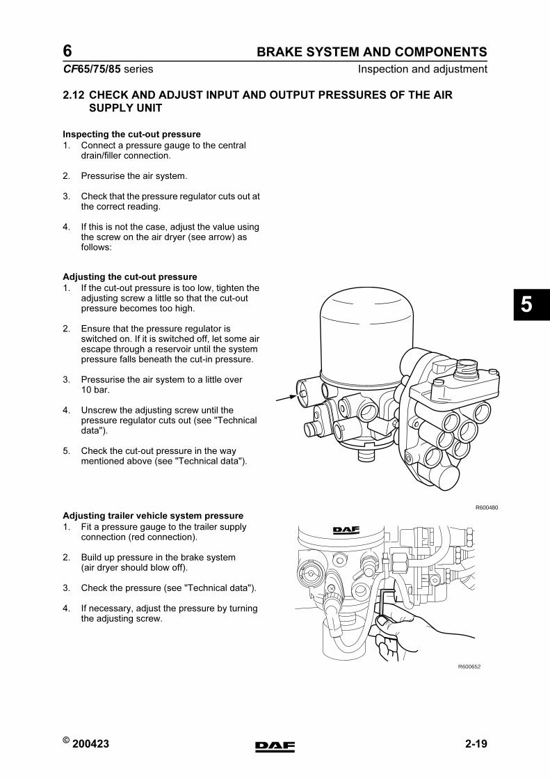
© 200423 2-19
Inspection and adjustment
BRAKE SYSTEM AND COMPONENTS
ΧΦ65/75/85 series
6
5
2.12 CHECK AND ADJUST INPUT AND OUTPUT PRESSURES OF THE AIR
SUPPLY UNIT
Inspecting the cut-out pressure
1. Connect a pressure gauge to the central drain/filler connection.
2. Pressurise the air system.
3. Check that the pressure regulator cuts out at the correct reading.
4. If this is not the case, adjust the value using the screw on the air dryer (see arrow) as follows:
Adjusting the cut-out pressure
1. If the cut-out pressure is too low, tighten the adjusting screw a little so that the cut-out pressure becomes too high.
2. Ensure that the pressure regulator is switched on. If it is switched off, let some air escape through a reservoir until the system pressure falls beneath the cut-in pressure.
3. Pressurise the air system to a little over 10 bar.
4. Unscrew the adjusting screw until the pressure regulator cuts out (see "Technical data").
5. Check the cut-out pressure in the way mentioned above (see "Technical data").
Adjusting trailer vehicle system pressure
1. Fit a pressure gauge to the trailer supply connection (red connection).
2. Build up pressure in the brake system (air dryer should blow off).
3. Check the pressure (see "Technical data").
4. If necessary, adjust the pressure by turning the adjusting screw.
R600480
R600652
https://www.truck-manuals.net/
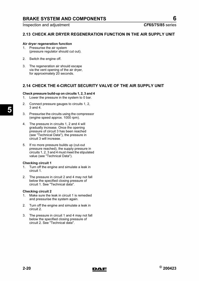
BRAKE SYSTEM AND COMPONENTS
2-20 © 200423
Inspection and adjustment
5
ΧΦ65/75/85 series
6
2.13 CHECK AIR DRYER REGENERATION FUNCTION IN THE AIR SUPPLY UNIT
Air dryer regeneration function
1. Pressurise the air system (pressure regulator should cut out).
2. Switch the engine off.
3. The regeneration air should escape via the vent opening of the air dryer, for approximately 20 seconds.
2.14 CHECK THE 4-CIRCUIT SECURITY VALVE OF THE AIR SUPPLY UNIT
Check pressure build-up on circuits 1, 2, 3 and 4
1. Lower the pressure in the system to 0 bar.
2. Connect pressure gauges to circuits 1, 2, 3 and 4.
3. Pressurise the circuits using the compressor (engine speed approx. 1000 rpm).
4. The pressure in circuits 1, 2 and 4 will gradually increase. Once the opening pressure of circuit 3 has been reached (see "Technical Data"), the pressure in circuit 3 will increase.
5. If no more pressure builds up (cut-out pressure reached), the supply pressure in circuits 1, 2, 3 and 4 must meet the stipulated value (see "Technical Data").
Checking circuit 1
1. Turn off the engine and simulate a leak in circuit 1.
2. The pressure in circuit 2 and 4 may not fall below the specified closing pressure of circuit 1. See "Technical data".
Checking circuit 2
1. Make sure the leak in circuit 1 is remedied and pressurise the system again.
2. Turn off the engine and simulate a leak in circuit 2.
3. The pressure in circuit 1 and 4 may not fall below the specified closing pressure of circuit 2. See "Technical data".
https://www.truck-manuals.net/
© 200423 2-21
Inspection and adjustment
BRAKE SYSTEM AND COMPONENTS
ΧΦ65/75/85 series
6
5
Checking circuit 3
1. Make sure the leak in circuit 2 is remedied and pressurise the system again.
2. Turn off the engine and simulate a leak in circuit 3 for the trailer circuit (connection point 23).
3. The pressure in circuit 1.2 and 4 may not fall below the specified closing pressure of circuit 3. See "Technical data".
4. The pressure in circuit 3 for the parking brake circuit (connection point 25) must remain secured by the check valve.
Checking circuit 4
1. Make sure the leak in circuit 3 is remedied and pressurise the system again.
2. Turn off the engine and simulate a leak in circuit 4.
3. The pressure in circuit 1 and 2 may not fall below the specified closing pressure of circuit 4. See "Technical data".
Checking circuit 3 flow-back function
1. Make sure the leak in circuit 4 is remedied and pressurise the system again.
2. Turn off the engine and simulate a leak in circuit 1.
3. The pressure in circuit 3 for the trailer circuit (connection point 23) will decrease to 0 bar when the pressure in circuit 1 has reached the activation pressure for the flow-back function. See "Technical data".
https://www.truck-manuals.net/
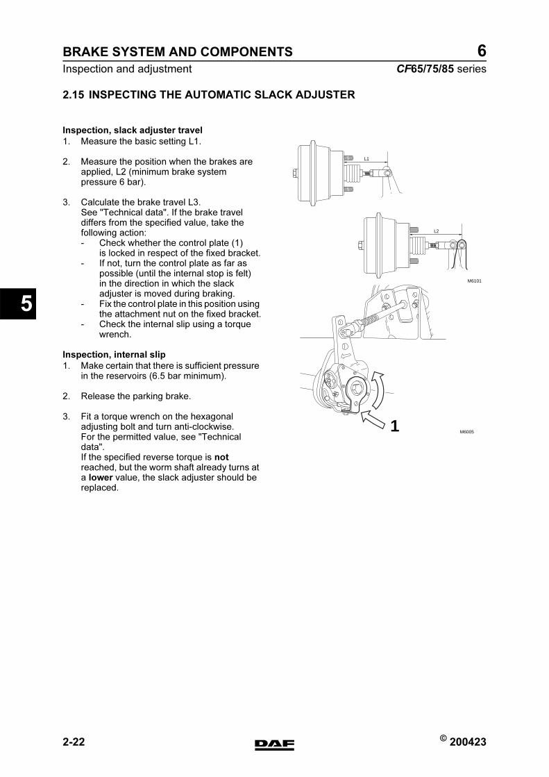
BRAKE SYSTEM AND COMPONENTS
2-22 © 200423
Inspection and adjustment
5
ΧΦ65/75/85 series
6
2.15 INSPECTING THE AUTOMATIC SLACK ADJUSTER
Inspection, slack adjuster travel
1. Measure the basic setting L1.
2. Measure the position when the brakes are applied, L2 (minimum brake system pressure 6 bar).
3. Calculate the brake travel L3. See "Technical data". If the brake travel differs from the specified value, take the following action:- Check whether the control plate (1)
is locked in respect of the fixed bracket.- If not, turn the control plate as far as
possible (until the internal stop is felt) in the direction in which the slack adjuster is moved during braking.
- Fix the control plate in this position using the attachment nut on the fixed bracket.
- Check the internal slip using a torque wrench.
Inspection, internal slip
1. Make certain that there is sufficient pressure in the reservoirs (6.5 bar minimum).
2. Release the parking brake.
3. Fit a torque wrench on the hexagonal adjusting bolt and turn anti-clockwise. For the permitted value, see "Technical data".If the specified reverse torque is not reached, but the worm shaft already turns at a lower value, the slack adjuster should be replaced.
M6101
L2
L1
M60051
https://www.truck-manuals.net/
© 200423 2-23
Inspection and adjustment
BRAKE SYSTEM AND COMPONENTS
ΧΦ65/75/85 series
6
5
Checking automatic slack adjuster for 09N044
axle
1. Check that the free travel in the slack adjuster lever from a position of rest to touching the brake shoes is between 12 and 16 mm, measured level with the locking pin.If the value differs from this, the slack adjuster should be turned back anti-clockwise until the correct travel is obtained.
2. When turning back the slack adjuster check that it makes a clicking noise.
3. When operating the brake, check that the adjuster is functioning properly. This can be done by fitting a ring spanner onto the adjusting bolt. The spanner should make a turn when the foot brake is operated. If it does not, the slack adjuster must be replaced.
https://www.truck-manuals.net/

BRAKE SYSTEM AND COMPONENTS
2-24 © 200423
Inspection and adjustment
5
ΧΦ65/75/85 series
6
2.16 INSPECTING THE DISC BRAKE AUTOMATIC SLACK ADJUSTER
1. Place chocks in front of and behind the wheels to prevent the vehicle from moving.
2. Put the parking brake in the driving position.
3. Remove the wheel.
4. Remove the covering cap from the slack adjuster.
5. Fit a ring spanner on the adapter and turn the hexagonal adjusting bolt together with the adapter anti-clockwise (2 - 3 clicks).
Note:Never turn the hexagonal adjusting bolt without using an adapter. The adapter is a torque safety and will break off when the torque is too high. Without the use of an adapter the mechanics in the brake calliper may become damaged when the torque is too high, so that replacement of the brake calliper may be necessary.
6. Leave the ring spanner on the adapter and depress the brake pedal 5 to 10 times at an output pressure of 2 bar.
7. Check that the ring spanner makes a clockwise turn every time the pedal is depressed. The turns of the ring spanner must decrease in line with the clearance.
8. After the inspection, lightly grease the sealing cap and replace it on the slack adjuster. See "Technical data".
R600468
https://www.truck-manuals.net/

© 200423 2-25
Inspection and adjustment
BRAKE SYSTEM AND COMPONENTS
ΧΦ65/75/85 series
6
5
2.17 INSPECTION, BRAKE DRUMS
For reasons of preservation, brake drums of new vehicles must be cleaned with a cleaning agent.
The brake drums must be lifted using a hoist. This is because there is a risk of limbs getting trapped.
Always be careful when braking with new brake drums and brake linings.
A brake drum which is thermally overloaded will show heat cracks. These heat cracks will become larger and deeper the longer the drum is used. Thermal stress will thus increase the formation of cracks.
Thermal stress may be caused by:- poor braking force distribution- seized brakes- jammed brake shafts or brake cylinders- insufficient clearance between brake lining
and brake drum with new brake linings- continuous application of the service brake
whilst driving.
Cracks that are permissible must be capable of being removed when the drum is reconditioned. See "Technical data".If the cracks cannot be completely removed during reconditioning of the brake drums, accelerated brake lining wear can be expected.If the brakes are once again thermally overloaded, the edges of the cracks will rise again, which will result in premature wear of the lining, due to abrasion.
A brake drum may also show burns and local hardened spots, also caused by high temperatures.Where the structure of the brake drum material has changed, these burns must be removed by reconditioning and grinding.If the spots cannot be removed, braking will always be accompanied by vibrations.The brake linings will always first show rough wear grooves at the respective spots.
A brake drum may be used until the internal diameter has reached the maximum value. See "Technical data".
As soon as this diameter is exceeded, the brake drum must be replaced.
R 6 00 128
50
0.7
https://www.truck-manuals.net/
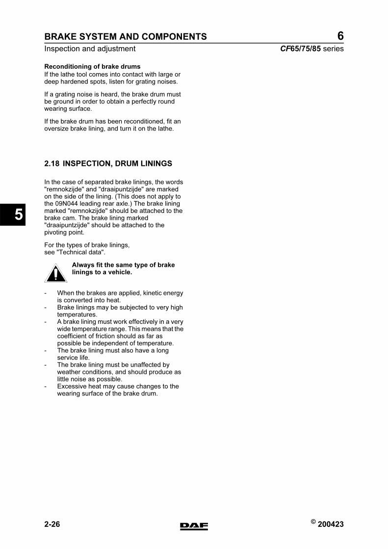
BRAKE SYSTEM AND COMPONENTS
2-26 © 200423
Inspection and adjustment
5
ΧΦ65/75/85 series
6
Reconditioning of brake drums
If the lathe tool comes into contact with large or deep hardened spots, listen for grating noises.
If a grating noise is heard, the brake drum must be ground in order to obtain a perfectly round wearing surface.
If the brake drum has been reconditioned, fit an oversize brake lining, and turn it on the lathe.
2.18 INSPECTION, DRUM LININGS
In the case of separated brake linings, the words "remnokzijde" and "draaipuntzijde" are marked on the side of the lining. (This does not apply to the 09N044 leading rear axle.) The brake lining marked "remnokzijde" should be attached to the brake cam. The brake lining marked "draaipuntzijde" should be attached to the pivoting point.
For the types of brake linings, see "Technical data".
Always fit the same type of brake linings to a vehicle.
- When the brakes are applied, kinetic energy is converted into heat.
- Brake linings may be subjected to very high temperatures.
- A brake lining must work effectively in a very wide temperature range. This means that the coefficient of friction should as far as possible be independent of temperature.
- The brake lining must also have a long service life.
- The brake lining must be unaffected by weather conditions, and should produce as little noise as possible.
- Excessive heat may cause changes to the wearing surface of the brake drum.
}
https://www.truck-manuals.net/

© 200423 2-27
Inspection and adjustment
BRAKE SYSTEM AND COMPONENTS
ΧΦ65/75/85 series
6
5
Brake lining (including brake shoes)
inspection points:
- braking performance after running in- glazing- moisture absorption (oil absorption)- lining wear- heat cracks- corrosion- swelling
Brake linings should be renewed when they have been contaminated by oil or grease, or when the lining is worn down to approx. 1 mm above the rivet head, or to the wear indicator. The thickness can be measured via the inspection holes in the back plates.
Corrosion
Brake shoes may exhibit considerable corrosion, as a result of excessive ageing and the action of moisture on the assembly face.
Incorrect bearing surface
The surface is no longer smooth. The lining no longer has a sufficient mounting surface at the edges of the rivet recess and ruptures during riveting. The lining could be released from the shoe and lifted. As a result, the clearance between lining and drum decreases or disappears completely.Even when the brakes are not applied, the temperature of the brake increases and, as a result, heat cracks may occur in the bearing surface of the brake drum.
Bearing pattern
When turning the brake lining, the lining will bear on the radius of the drum with the entire brake surface. Such a bearing pattern guarantees the best possible breaking performance from the beginning. The turning of the brake lining may be carried out on a brake lining lathe, or with a special dummy back plate on a special lathe.The bearing pattern of the brake lining can be improved by turning the brake lining to a diameter which is max. 1.0 mm smaller than the drum diameter. So, in the case of a brake drum diameter of 420 mm the brake lining should be turned to a max. diameter of 419 mm.
M6002
R600129
https://www.truck-manuals.net/

BRAKE SYSTEM AND COMPONENTS
2-28 © 200423
Inspection and adjustment
5
ΧΦ65/75/85 series
6
Wheel brake with modified lining diameter
(see drawing)
The lining will bear on the centre of the lining length first, after which the bearing pattern is extended from the centre towards the ends. This will prevent an (unduly) heavy self-servo action during the running-in period.
The brake lining must be turned gradually; i.e. not too much lining material should be removed in one operation.If this instruction is not followed, the lathe tool will bend and be inclined to lift the leading brake shoe of the brake cam. The initial bearing pattern will then not be at its best.It is not necessary to turn "clean" the entire surface. It is sufficient to touch 75% of the surface with the lathe tool.
A wheel brake lining with insufficient bearing
surface
The ends of the brake lining are still free. As a result, the load on the smaller brake lining surface will be considerably heavier at the same press-on force. As a result, the lining will be squeezed; the temperature will increase and there will be accelerated lining wear, until the braking surface is eventually correct.In the case of reconditioned brake drums, it is recommended that a new lining should be turned to the radius of the brake drum after it has been fitted.
R600130
R600131
https://www.truck-manuals.net/
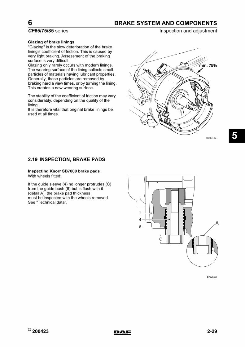
© 200423 2-29
Inspection and adjustment
BRAKE SYSTEM AND COMPONENTS
ΧΦ65/75/85 series
6
5
Glazing of brake linings
"Glazing" is the slow deterioration of the brake lining's coefficient of friction. This is caused by very light braking. Assessment of the braking surface is very difficult.Glazing only rarely occurs with modern linings.The wearing surface of the lining collects small particles of materials having lubricant properties. Generally, these particles are removed by braking hard a view times, or by turning the lining.This creates a new wearing surface.
The stability of the coefficient of friction may vary considerably, depending on the quality of the lining.It is therefore vital that original brake linings be used at all times.
2.19 INSPECTION, BRAKE PADS
Inspecting Knorr SB7000 brake pads
With wheels fitted:
If the guide sleeve (4) no longer protrudes (C) from the guide bush (6) but is flush with it (detail A), the brake pad thickness must be inspected with the wheels removed. See "Technical data".
R600132
min. 75%
C
1
4
6
R600481
A
https://www.truck-manuals.net/

BRAKE SYSTEM AND COMPONENTS
2-30 © 200423
Inspection and adjustment
5
ΧΦ65/75/85 series
6
Inspecting Knorr SN7000 brake pads
With wheels fitted:
The brake pad thickness can be checked on the basis of the position of the guide bush relative to the rubber bush.
At maximum brake pad thickness the rubber cover is stretched. Wear of the brake pads and movement of the brake calliper along the guide bushes will cause the rubber cover to roll up.
As soon as the transition from the ribbed section of the rubber cover to the smooth section (A) starts to roll inward, the brake pad thickness is to be checked with the wheels removed. See "Technical data".
A
A
AR600730
https://www.truck-manuals.net/

© 200423 2-31
Inspection and adjustment
BRAKE SYSTEM AND COMPONENTS
ΧΦ65/75/85 series
6
5
2.20 INSPECTION, BRAKE DISCS
1. Remove the wheels.
2. Measure the disc thickness at different points to find the thinnest measurement. Compare the reading with the technical data. See "Technical data".
3. Check the brake discs for signs of wear. See "Technical data".
Note:The brake discs may be turned. See "Technical data".
https://www.truck-manuals.net/

BRAKE SYSTEM AND COMPONENTS
2-32 © 200423
Inspection and adjustment
5
ΧΦ65/75/85 series
6
2.21 INSPECTION, BRAKE CALLIPER PLAY
Inspection of the free movement of the brake calliper guide over the brake calliper carrier is the most important thing. That is why initially a simple inspection is carried out on the vehicle of the axial movement of the brake calliper when it is fitted.
General inspection
1. Push and pull the brake calliper back and forth several times in the axial direction (A). This requires considerable effort.
2. Check the play of the brake calliper in the axial direction (A). See "Technical data".If the measured play is incorrect or the brake calliper cannot be moved along the guide bushes, it must be checked in more detail as follows.
Inspection of sliding ability
1. Remove the brake pads.
2. Turn the thrust pieces back completely using the adjusting bolt and the adapter.
3. Clean the guide bushes where they are accessible.
4. Check whether the brake calliper can be moved by hand along the full distance (more than 25 mm) (so without the use of tools).
Inspecting guide bush bearing play
1. Pull the brake calliper as far as possible towards the outside of the vehicle (B).
R600708
A
B
R600709
https://www.truck-manuals.net/
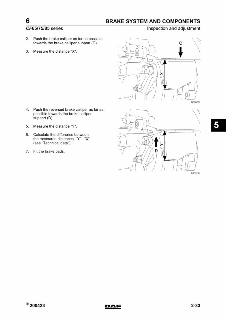
© 200423 2-33
Inspection and adjustment
BRAKE SYSTEM AND COMPONENTS
ΧΦ65/75/85 series
6
5
2. Push the brake calliper as far as possible towards the brake calliper support (C).
3. Measure the distance "X".
4. Push the reversed brake calliper as far as possible towards the brake calliper support (D).
5. Measure the distance "Y".
6. Calculate the difference between the measured distances, "Y" - "X" (see "Technical data").
7. Fit the brake pads.
X
R600710
C
Y
R600711
D
https://www.truck-manuals.net/
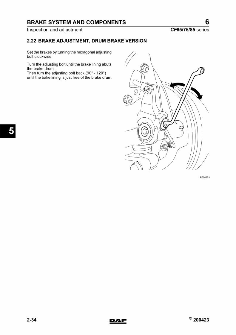
BRAKE SYSTEM AND COMPONENTS
2-34 © 200423
Inspection and adjustment
5
ΧΦ65/75/85 series
6
2.22 BRAKE ADJUSTMENT, DRUM BRAKE VERSION
Set the brakes by turning the hexagonal adjusting bolt clockwise.
Turn the adjusting bolt until the brake lining abuts the brake drum.Then turn the adjusting bolt back (90 - 120) until the bake lining is just free of the brake drum.
R600253
https://www.truck-manuals.net/
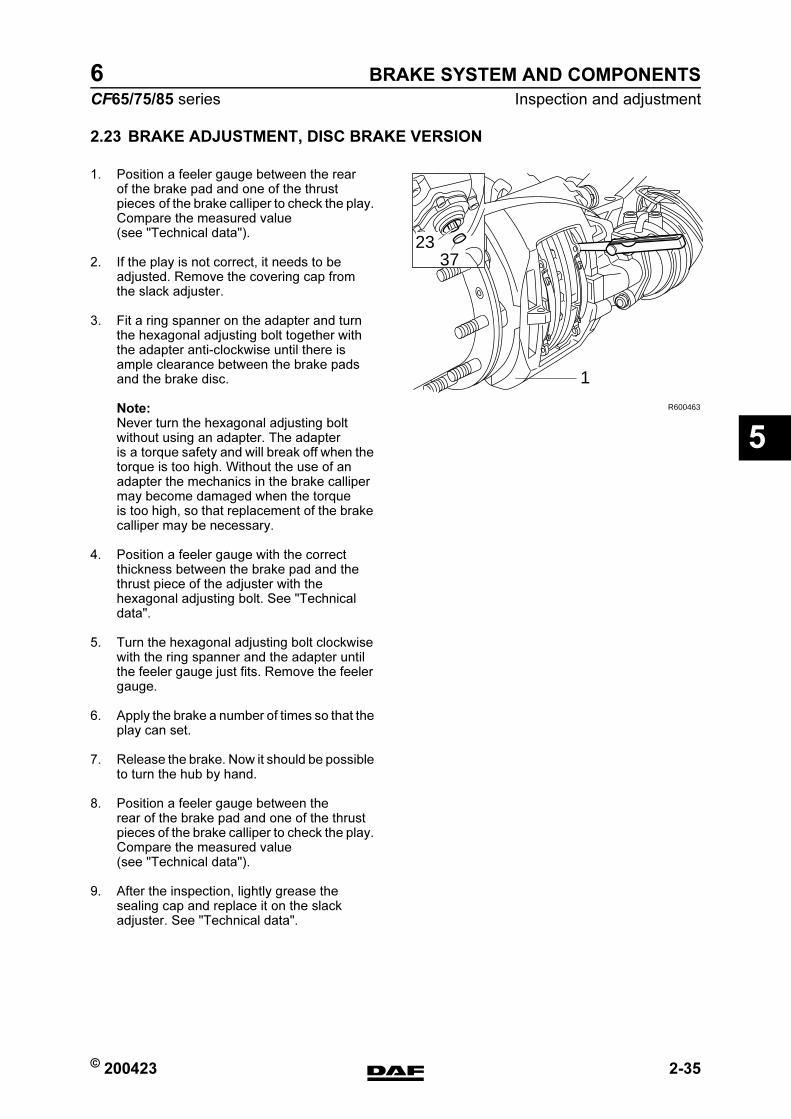
© 200423 2-35
Inspection and adjustment
BRAKE SYSTEM AND COMPONENTS
ΧΦ65/75/85 series
6
5
2.23 BRAKE ADJUSTMENT, DISC BRAKE VERSION
1. Position a feeler gauge between the rear of the brake pad and one of the thrust pieces of the brake calliper to check the play. Compare the measured value (see "Technical data").
2. If the play is not correct, it needs to be adjusted. Remove the covering cap from the slack adjuster.
3. Fit a ring spanner on the adapter and turn the hexagonal adjusting bolt together with the adapter anti-clockwise until there is ample clearance between the brake pads and the brake disc.
Note:Never turn the hexagonal adjusting bolt without using an adapter. The adapter is a torque safety and will break off when the torque is too high. Without the use of an adapter the mechanics in the brake calliper may become damaged when the torque is too high, so that replacement of the brake calliper may be necessary.
4. Position a feeler gauge with the correct thickness between the brake pad and the thrust piece of the adjuster with the hexagonal adjusting bolt. See "Technical data".
5. Turn the hexagonal adjusting bolt clockwise with the ring spanner and the adapter until the feeler gauge just fits. Remove the feeler gauge.
6. Apply the brake a number of times so that the play can set.
7. Release the brake. Now it should be possible to turn the hub by hand.
8. Position a feeler gauge between the rear of the brake pad and one of the thrust pieces of the brake calliper to check the play. Compare the measured value (see "Technical data").
9. After the inspection, lightly grease the sealing cap and replace it on the slack adjuster. See "Technical data".
2337
1
R600463
https://www.truck-manuals.net/
BRAKE SYSTEM AND COMPONENTS
2-36 © 200423
Inspection and adjustment
5
ΧΦ65/75/85 series
6
2.24 INSPECTION, AIR TIGHTNESS
Air tightness
If the brake system of a vehicle has been charged to the maximum pressure, it should generally be possible to drive the vehicle away after a period of 16 hours of uninterrupted standstill, without first having to charge the brake system to sufficient operating pressure.This implies a maximum pressure drop of approx. 0.4 bar per hour at normal system pressure.
Note:Always connect auxiliary consumers and accessories to circuit 4.
https://www.truck-manuals.net/
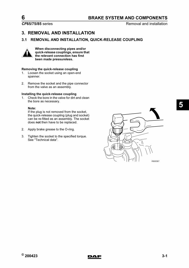
© 200423 3-1
Removal and installation
BRAKE SYSTEM AND COMPONENTS
ΧΦ65/75/85 series
6
5
3. REMOVAL AND INSTALLATION
3.1 REMOVAL AND INSTALLATION, QUICK-RELEASE COUPLING
When disconnecting pipes and/or quick-release couplings, ensure that the relevant connection has first been made pressureless.
Removing the quick-release coupling
1. Loosen the socket using an open-end spanner.
2. Remove the socket and the pipe connector from the valve as an assembly.
Installing the quick-release coupling
1. Check the bore in the valve for dirt and clean the bore as necessary.
Note:If the plug is not removed from the socket, the quick-release coupling (plug and socket) can be re-fitted as an assembly. The socket does not then have to be replaced.
2. Apply brake grease to the O-ring.
3. Tighten the socket to the specified torque. See "Technical data".
}
R600367
https://www.truck-manuals.net/
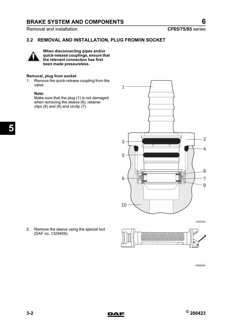
BRAKE SYSTEM AND COMPONENTS
3-2 © 200423
Removal and installation
5
ΧΦ65/75/85 series
6
3.2 REMOVAL AND INSTALLATION, PLUG FROM/IN SOCKET
When disconnecting pipes and/or quick-release couplings, ensure that the relevant connection has first been made pressureless.
Removal, plug from socket
1. Remove the quick-release coupling from the valve.
Note:Make sure that the plug (1) is not damaged when removing the sleeve (6), retainer clips (8) and (9) and circlip (7).
2. Remove the sleeve using the special tool (DAF no. 1329459).
}
R600365
2
1
3
5
6
10
4
8
79
R600404
https://www.truck-manuals.net/
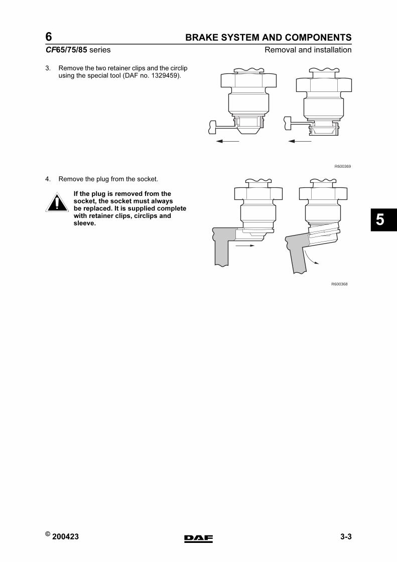
© 200423 3-3
Removal and installation
BRAKE SYSTEM AND COMPONENTS
ΧΦ65/75/85 series
6
5
3. Remove the two retainer clips and the circlip using the special tool (DAF no. 1329459).
4. Remove the plug from the socket.
If the plug is removed from the socket, the socket must always be replaced. It is supplied complete with retainer clips, circlips and sleeve.
R600369
R600368
}
https://www.truck-manuals.net/
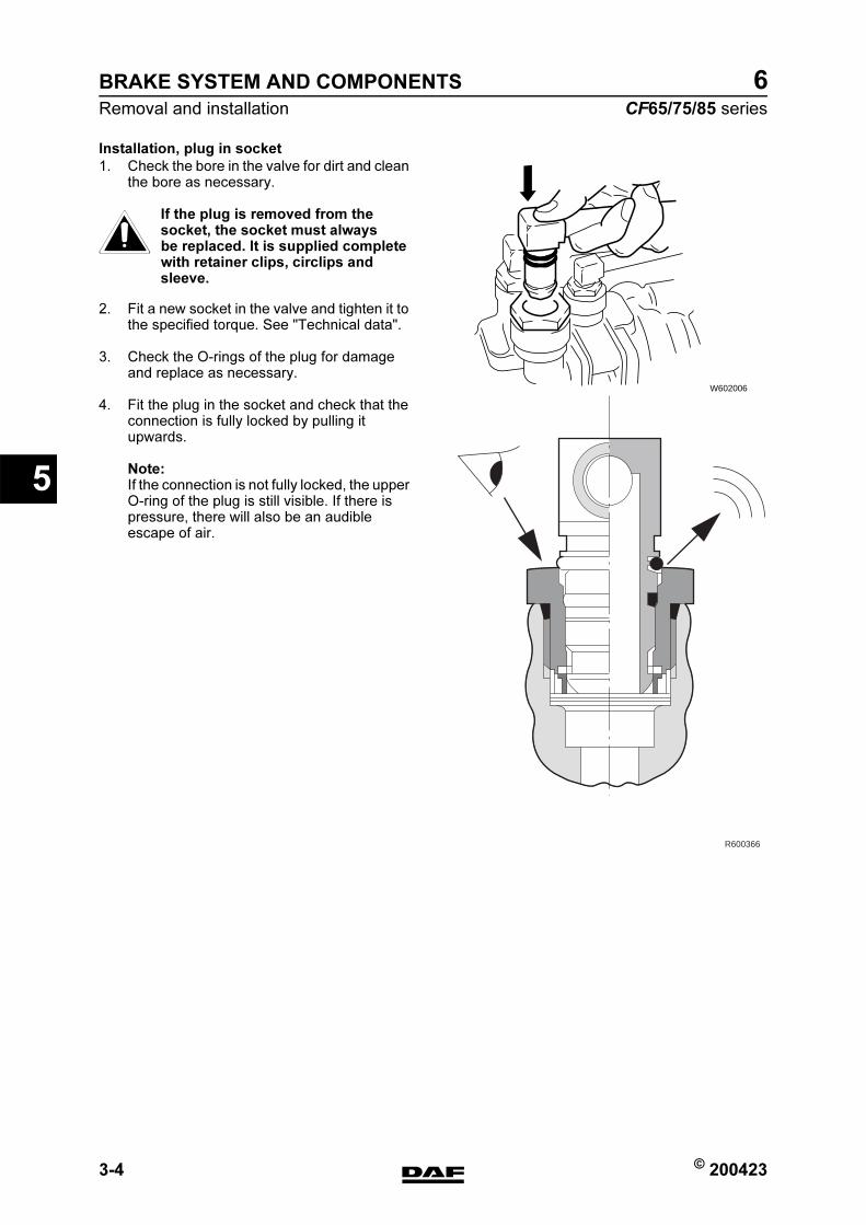
BRAKE SYSTEM AND COMPONENTS
3-4 © 200423
Removal and installation
5
ΧΦ65/75/85 series
6
Installation, plug in socket
1. Check the bore in the valve for dirt and clean the bore as necessary.
If the plug is removed from the socket, the socket must always be replaced. It is supplied complete with retainer clips, circlips and sleeve.
2. Fit a new socket in the valve and tighten it to the specified torque. See "Technical data".
3. Check the O-rings of the plug for damage and replace as necessary.
4. Fit the plug in the socket and check that the connection is fully locked by pulling it upwards.
Note:If the connection is not fully locked, the upper O-ring of the plug is still visible. If there is pressure, there will also be an audible escape of air.
W602006
R600366
}
https://www.truck-manuals.net/

© 200423 3-5
Removal and installation
BRAKE SYSTEM AND COMPONENTS
ΧΦ65/75/85 series
6
5
3.3 REMOVAL AND INSTALLATION OF PIPE ON PIPE CONNECTOR
When disconnecting pipes and/or quick-release couplings, ensure that the relevant connection has first been made pressureless.
Removal of pipe on pipe connector
1. Remove the plug from the socket.
2. Cut the pipe at right angles just in front of the pipe connector.
Note:When removing the remainder of the pipe, do not use any sharp objects. This is to avoid damaging the pipe connector. Damage to the pipe connector could result in leakage.Remove the remainder of the pipe using heat or the "cutting point" of a soldering iron.
Installation of pipe on pipe connector
1. Check that there are no burrs in the pipe.
2. Check the pipe connector for damage. If the pipe connector is damaged, the pipe connector and socket must be replaced.
3. Check that the pipe connector is clean and grease-free.
4. Fit the plastic cap onto the plug to prevent it from being damaged during installation.
5. Using the special tool (DAF no. 0694829) and a plastic hammer, attach the pipe to the pipe connector.
}
W602009
https://www.truck-manuals.net/
BRAKE SYSTEM AND COMPONENTS
3-6 © 200423
Removal and installation
5
ΧΦ65/75/85 series
6
3.4 REMOVAL AND INSTALLATION, BRAKE CYLINDER
Removing disc brake cylinder
1. Remove the compressed air connection to the brake cylinder.
2. Take the attachment nuts off the brake cylinder and remove it.
Fitting disc brake cylinder
1. Fit the brake cylinder onto the support and tighten the attachment nuts to the specified torque. See "Technical data".
2. Connect the air pipe.
Removing drum brake cylinder
1. Turn the brakes back until there is no more tension on the yoke pin.
2. Remove the split pin and the yoke pin.
3. Remove the compressed air connection to the brake cylinder.
4. Take the attachment nuts off the brake cylinder and remove it.
Fitting drum brake cylinder
1. Fit the brake cylinder onto the support and tighten the attachment nuts to the specified torque. See "Technical data".
2. Insert the yoke pin and split pin.
3. Connect the air pipe.
4. Adjust the brakes. See "Inspection and adjustment".
https://www.truck-manuals.net/
© 200423 3-7
Removal and installation
BRAKE SYSTEM AND COMPONENTS
ΧΦ65/75/85 series
6
5
3.5 REMOVAL AND INSTALLATION, SPRING BRAKE CYLINDER
Removal, spring brake cylinder on drum brake
1. Place chocks in front of and behind the wheels and ensure that there is sufficient system pressure (> 7.5 bar).
2. Place the parking brake valve in the "Driving" position. Unscrew the release bolt in the spring brake cylinder with a 24-mm spanner as far as possible (anti-clockwise).
3. Place the parking brake valve in the "Parking" position and disconnect the two air pipes from the spring brake cylinder.
4. Remove the yoke pin from the yoke and the brake lever.
5. Remove the attachment nuts and take the spring brake cylinder from the support.
Installation, spring brake cylinder on drum
brake
1. Fit the spring brake cylinder onto the support and tighten it to the specified torque. See "Technical data".
2. Pass the yoke pin through the yoke and the brake lever. The bracket should be flat (tolerance < 0.4 mm).
3. Connect the air pipes:connection point (11); service brake,connection point (12); parking brake,
4. Pressurise the air reservoirs and put the parking brake valve in the "Driving" position. Turn the release bolt all the way in and tighten it to the specified torque. See "Technical data".
5. Check the connections for leakage.
Removal, spring brake cylinder on disc brakes
Note:Prevent dirt from entering the disc brake construction and cover the opening.
1. Place chocks in front of and behind the wheels and ensure that there is sufficient system pressure (> 7.5 bar).
2. Put the parking brake valve in the "Driving" position (provide sufficient system pressure: + 6 bar). Unscrew the release bolt in the spring brake cylinder with a 24-mm spanner as far as possible (anti-clockwise).
https://www.truck-manuals.net/

BRAKE SYSTEM AND COMPONENTS
3-8 © 200423
Removal and installation
5
ΧΦ65/75/85 series
6
3. Place the parking brake valve in the "Parking" position and disconnect the two air pipes from the spring brake cylinder.
4. Remove the attachment nuts and take the spring brake cylinder from the support.
Installation, spring brake cylinder on disc
brakes
1. Fit the spring brake cylinder onto the support and tighten the attachment nuts to the specified torque. See "Technical data".
2. Connect the air pipes:
3. Put the parking brake valve in the "Driving" position (provide sufficient system pressure: approx. 6 bar). Turn the release bolt all the way in and tighten it to the specified torque. See "Technical data".
4. Check the connections for leakage.
https://www.truck-manuals.net/
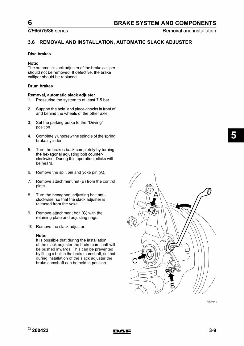
© 200423 3-9
Removal and installation
BRAKE SYSTEM AND COMPONENTS
ΧΦ65/75/85 series
6
5
3.6 REMOVAL AND INSTALLATION, AUTOMATIC SLACK ADJUSTER
Disc brakes
Note:The automatic slack adjuster of the brake calliper should not be removed. If defective, the brake calliper should be replaced.
Drum brakes
Removal, automatic slack adjuster
1. Pressurise the system to at least 7.5 bar.
2. Support the axle, and place chocks in front of and behind the wheels of the other axle.
3. Set the parking brake to the "Driving" position.
4. Completely unscrew the spindle of the spring brake cylinder.
5. Turn the brakes back completely by turning the hexagonal adjusting bolt counter-clockwise. During this operation, clicks will be heard.
6. Remove the split pin and yoke pin (A).
7. Remove attachment nut (B) from the control plate.
8. Turn the hexagonal adjusting bolt anti-clockwise, so that the slack adjuster is released from the yoke.
9. Remove attachment bolt (C) with the retaining plate and adjusting rings.
10. Remove the slack adjuster.
Note:It is possible that during the installation of the slack adjuster the brake camshaft will be pushed inwards. This can be prevented by fitting a bolt in the brake camshaft, so that during installation of the slack adjuster the brake camshaft can be held in position.
R600141
A
C
B
https://www.truck-manuals.net/
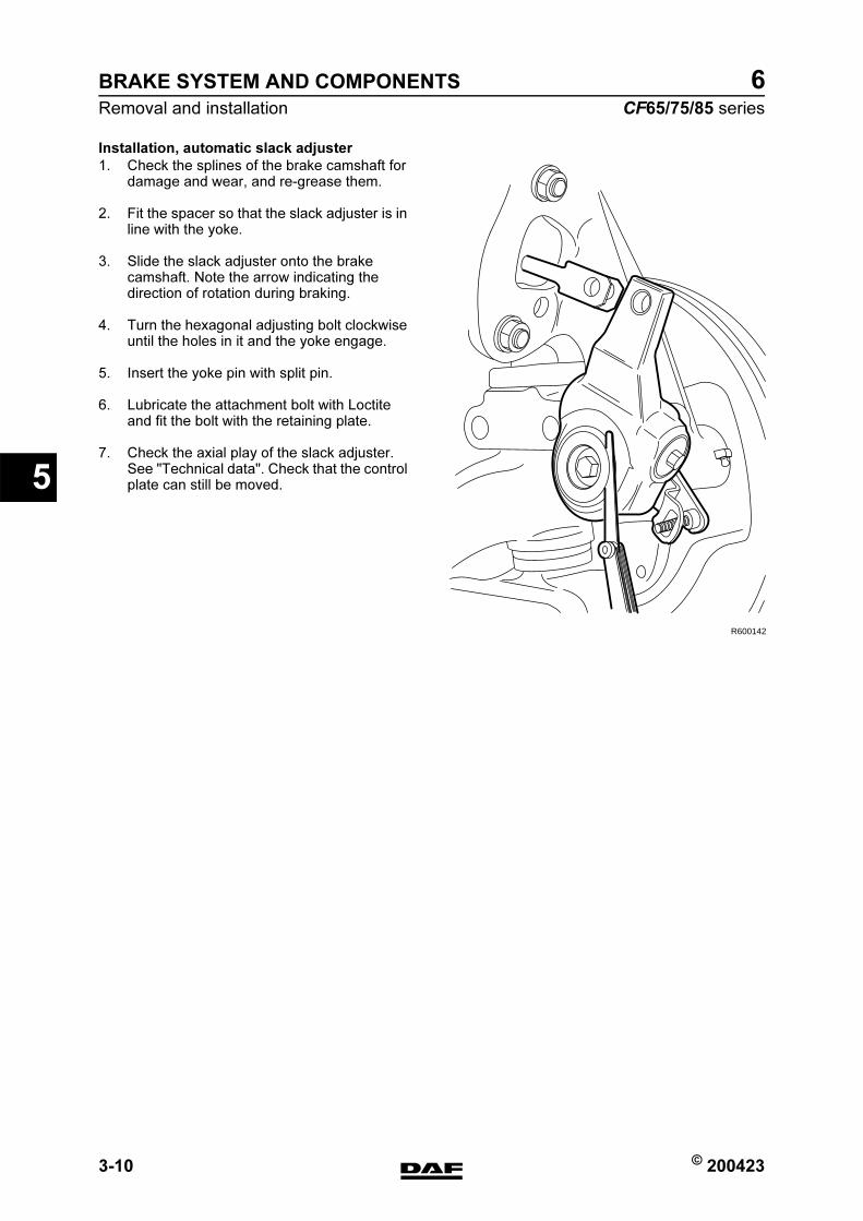
BRAKE SYSTEM AND COMPONENTS
3-10 © 200423
Removal and installation
5
ΧΦ65/75/85 series
6
Installation, automatic slack adjuster
1. Check the splines of the brake camshaft for damage and wear, and re-grease them.
2. Fit the spacer so that the slack adjuster is in line with the yoke.
3. Slide the slack adjuster onto the brake camshaft. Note the arrow indicating the direction of rotation during braking.
4. Turn the hexagonal adjusting bolt clockwise until the holes in it and the yoke engage.
5. Insert the yoke pin with split pin.
6. Lubricate the attachment bolt with Loctite and fit the bolt with the retaining plate.
7. Check the axial play of the slack adjuster. See "Technical data". Check that the control plate can still be moved.
R600142
https://www.truck-manuals.net/

© 200423 3-11
Removal and installation
BRAKE SYSTEM AND COMPONENTS
ΧΦ65/75/85 series
6
5
8. Turn the control plate as far as possible (until the internal stop is felt) in the direction in which the slack adjuster is moved during braking. Fix the control plate in this position using the attachment nut on the fixed bracket.
9. Adjust the brakes. See "Inspection and adjustment".
R600143
https://www.truck-manuals.net/

BRAKE SYSTEM AND COMPONENTS
3-12 © 200423
Removal and installation
5
ΧΦ65/75/85 series
6
3.7 REMOVAL AND INSTALLATION, BRAKE DRUM
Removal, brake drum
1. Pressurise the air system.
2. Place chocks in front of and behind the wheels of an axle on which you are not working.
3. Release the parking brake by means of the parking brake valve or by removing the release bolts from the spring brake cylinders.
4. Turn the automatic slack adjuster back completely.
5. Unscrew the wheel nuts.
6. Jack up the axle in question.
7. Support the axle with stands.
8. Remove the wheels.
9. Remove the two attachment bolts (A) from the brake drum.
10. Insert two jack screws in the threaded holes (B).
11. Note:Never use a pneumatic tool for tightening the jack screws.Tighten them evenly by hand. This brings the brake drum to pressure. Use a copper punch to work the brake drum from the hub. Use lifting gear to remove the brake drum.
Installation, brake drum
1. Clean the fitting edge of the brake drum and the wheel rim with a steel wire brush.
2. Then smear the fitting edge lightly with grease. This grease layer should prevent the brake drum from rusting tight.
3. Remove the jack screws from the brake drum.
4. Fit the brake drum using the lifting gear.
5. Fit two wheel nuts opposite one another.
6. Tighten these wheel nuts evenly until the brake drum is correctly on the hub.
7. Remove the wheel nuts.
8. Fit the attachment bolts for the brake drum.
R600144
B
B
A
A
https://www.truck-manuals.net/
© 200423 3-13
Removal and installation
BRAKE SYSTEM AND COMPONENTS
ΧΦ65/75/85 series
6
5
9. Fit the wheels and wheel nuts and tighten the nuts evenly, in the correct order. See group 7 of the workshop manual.
10. Adjust the brakes. See "Inspection and adjustment".
11. Remove the jack and chocks from the rear wheels. If the spring brake cylinder was mechanically released, the release bolt should be screwed back in and tightened to the specified torque. See "Technical data". The pressure in the spring brake cylinder circuit should be at least 5 bar.
https://www.truck-manuals.net/

BRAKE SYSTEM AND COMPONENTS
3-14 © 200423
Removal and installation
5
ΧΦ65/75/85 series
6
3.8 REMOVAL AND INSTALLATION, BRAKE SHOES 1354, 1355T REAR AXLE
Removal, brake shoes
1. Remove the brake drum.
2. Remove the circlips, felt rings and sealing rings from one side of the brake shoe.
3. Remove the lock bolts or lock studs from the anchor pins.
R600145
https://www.truck-manuals.net/
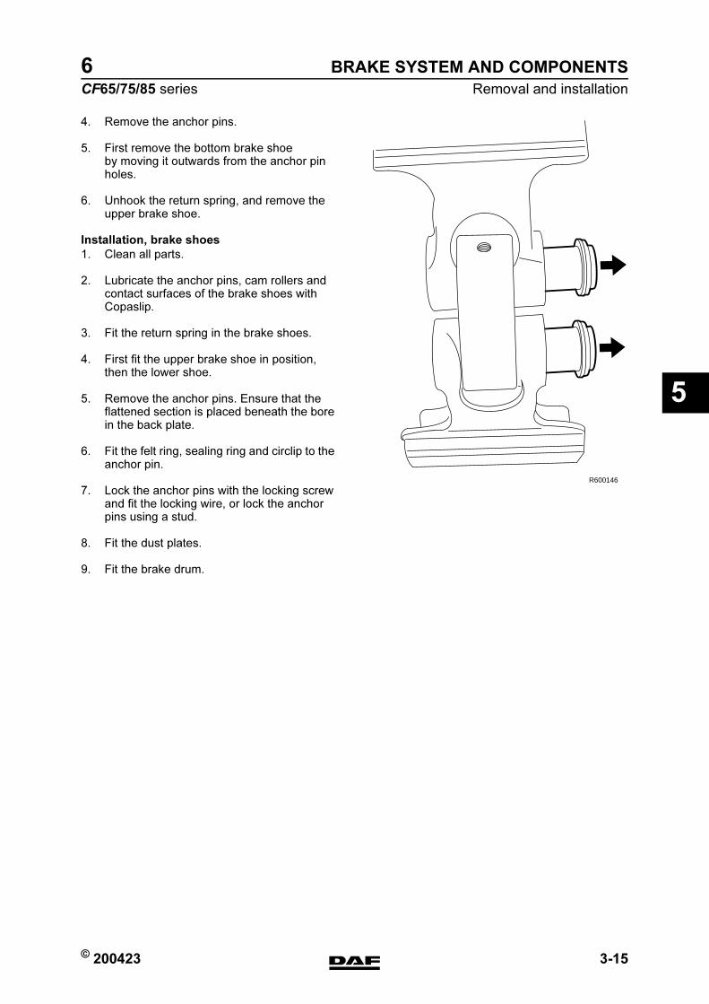
© 200423 3-15
Removal and installation
BRAKE SYSTEM AND COMPONENTS
ΧΦ65/75/85 series
6
5
4. Remove the anchor pins.
5. First remove the bottom brake shoe by moving it outwards from the anchor pin holes.
6. Unhook the return spring, and remove the upper brake shoe.
Installation, brake shoes
1. Clean all parts.
2. Lubricate the anchor pins, cam rollers and contact surfaces of the brake shoes with Copaslip.
3. Fit the return spring in the brake shoes.
4. First fit the upper brake shoe in position, then the lower shoe.
5. Remove the anchor pins. Ensure that the flattened section is placed beneath the bore in the back plate.
6. Fit the felt ring, sealing ring and circlip to the anchor pin.
7. Lock the anchor pins with the locking screw and fit the locking wire, or lock the anchor pins using a stud.
8. Fit the dust plates.
9. Fit the brake drum.
R600146
https://www.truck-manuals.net/
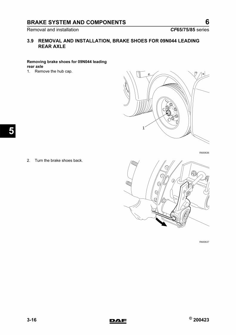
BRAKE SYSTEM AND COMPONENTS
3-16 © 200423
Removal and installation
5
ΧΦ65/75/85 series
6
3.9 REMOVAL AND INSTALLATION, BRAKE SHOES FOR 09N044 LEADING
REAR AXLE
Removing brake shoes for 09N044 leading
rear axle
1. Remove the hub cap.
2. Turn the brake shoes back.
R600636
1
R600637
https://www.truck-manuals.net/
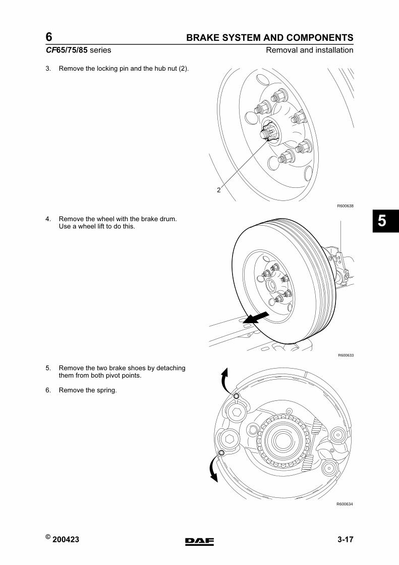
© 200423 3-17
Removal and installation
BRAKE SYSTEM AND COMPONENTS
ΧΦ65/75/85 series
6
5
3. Remove the locking pin and the hub nut (2).
4. Remove the wheel with the brake drum. Use a wheel lift to do this.
5. Remove the two brake shoes by detaching them from both pivot points.
6. Remove the spring.
R600638
2
R600633
R600634
https://www.truck-manuals.net/

BRAKE SYSTEM AND COMPONENTS
3-18 © 200423
Removal and installation
5
ΧΦ65/75/85 series
6
Installing brake shoes for 09N044 leading rear
axle
1. Fit the spring between the two brake shoes.
2. Fit the two brake shoes and press them over the pivot points.
3. Fit the wheel and the brake drum. Before re-fitting, check the condition of the brake drum and the bearing.
4. Install the hub nut, adjust the wheel bearing play and install the hub cap.
R600635
A
A
https://www.truck-manuals.net/

© 200423 3-19
Removal and installation
BRAKE SYSTEM AND COMPONENTS
ΧΦ65/75/85 series
6
5
3.10 INSTALLATION, BRAKE LINING ON BRAKE SHOE
A brake lining should be riveted correctly with a riveting machine, to prevent damage such as cracks in the rivet surface. For that reason, always use the specified rivets. Use the special tool (DAF no. 1240000) for riveting the brake lining.
1. Replace the brake lining when it has worn down to the wear indicator or to approximately 1 mm above the rivet head. The thickness can be measured via the inspection holes in the back plates.The brake lining should also be replaced if oil or grease has worked into it.
R600133
M6002
M6012
https://www.truck-manuals.net/
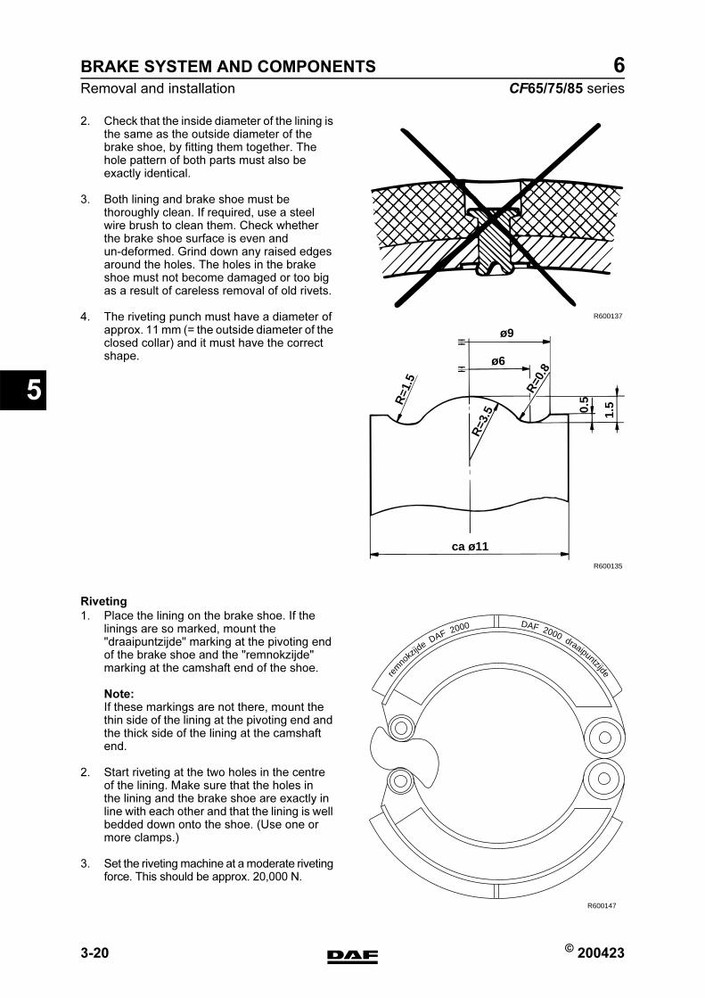
BRAKE SYSTEM AND COMPONENTS
3-20 © 200423
Removal and installation
5
ΧΦ65/75/85 series
6
2. Check that the inside diameter of the lining is the same as the outside diameter of the brake shoe, by fitting them together. The hole pattern of both parts must also be exactly identical.
3. Both lining and brake shoe must be thoroughly clean. If required, use a steel wire brush to clean them. Check whether the brake shoe surface is even and un-deformed. Grind down any raised edges around the holes. The holes in the brake shoe must not become damaged or too big as a result of careless removal of old rivets.
4. The riveting punch must have a diameter of approx. 11 mm (= the outside diameter of the closed collar) and it must have the correct shape.
Riveting
1. Place the lining on the brake shoe. If the linings are so marked, mount the "draaipuntzijde" marking at the pivoting end of the brake shoe and the "remnokzijde" marking at the camshaft end of the shoe.
Note:If these markings are not there, mount the thin side of the lining at the pivoting end and the thick side of the lining at the camshaft end.
2. Start riveting at the two holes in the centre of the lining. Make sure that the holes in the lining and the brake shoe are exactly in line with each other and that the lining is well bedded down onto the shoe. (Use one or more clamps.)
3. Set the riveting machine at a moderate riveting force. This should be approx. 20,000 N.
R600137
R600135
ø9
ca ø11
0.5
1.5
R=3
.5
R=1
.5
ø6
R=0
.8
rem
nokz
ijde
DAF 2000 DAF 2000 draaipuntzijde
R600147
https://www.truck-manuals.net/
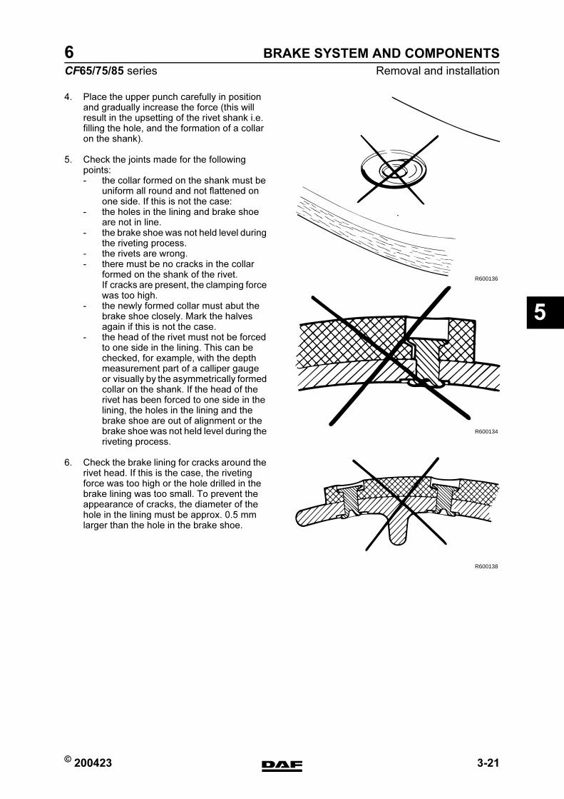
© 200423 3-21
Removal and installation
BRAKE SYSTEM AND COMPONENTS
ΧΦ65/75/85 series
6
5
4. Place the upper punch carefully in position and gradually increase the force (this will result in the upsetting of the rivet shank i.e. filling the hole, and the formation of a collar on the shank).
5. Check the joints made for the following points:- the collar formed on the shank must be
uniform all round and not flattened on one side. If this is not the case:
- the holes in the lining and brake shoe are not in line.
- the brake shoe was not held level during the riveting process.
- the rivets are wrong.- there must be no cracks in the collar
formed on the shank of the rivet. If cracks are present, the clamping force was too high.
- the newly formed collar must abut the brake shoe closely. Mark the halves again if this is not the case.
- the head of the rivet must not be forced to one side in the lining. This can be checked, for example, with the depth measurement part of a calliper gauge or visually by the asymmetrically formed collar on the shank. If the head of the rivet has been forced to one side in the lining, the holes in the lining and the brake shoe are out of alignment or the brake shoe was not held level during the riveting process.
6. Check the brake lining for cracks around the rivet head. If this is the case, the riveting force was too high or the hole drilled in the brake lining was too small. To prevent the appearance of cracks, the diameter of the hole in the lining must be approx. 0.5 mm larger than the hole in the brake shoe.
R600136
R600134
R600138
https://www.truck-manuals.net/
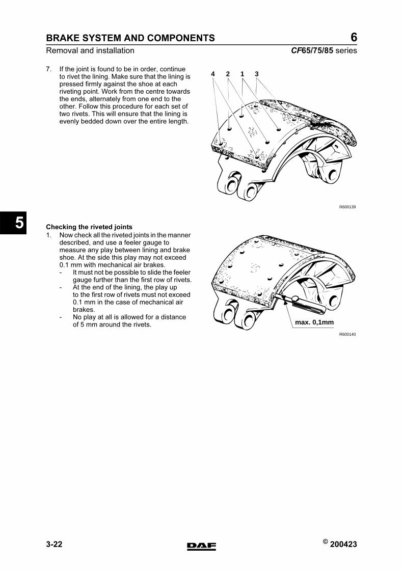
BRAKE SYSTEM AND COMPONENTS
3-22 © 200423
Removal and installation
5
ΧΦ65/75/85 series
6
7. If the joint is found to be in order, continue to rivet the lining. Make sure that the lining is pressed firmly against the shoe at each riveting point. Work from the centre towards the ends, alternately from one end to the other. Follow this procedure for each set of two rivets. This will ensure that the lining is evenly bedded down over the entire length.
Checking the riveted joints
1. Now check all the riveted joints in the manner described, and use a feeler gauge to measure any play between lining and brake shoe. At the side this play may not exceed 0.1 mm with mechanical air brakes.- It must not be possible to slide the feeler
gauge further than the first row of rivets.- At the end of the lining, the play up
to the first row of rivets must not exceed 0.1 mm in the case of mechanical air brakes.
- No play at all is allowed for a distance of 5 mm around the rivets.
R600139
4 2 1 3
R600140
max. 0,1mm
https://www.truck-manuals.net/
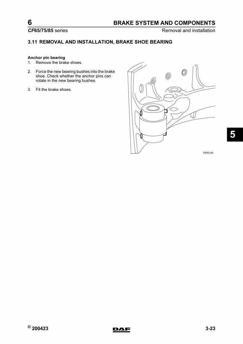
© 200423 3-23
Removal and installation
BRAKE SYSTEM AND COMPONENTS
ΧΦ65/75/85 series
6
5
3.11 REMOVAL AND INSTALLATION, BRAKE SHOE BEARING
Anchor pin bearing
1. Remove the brake shoes.
2. Force the new bearing bushes into the brake shoe. Check whether the anchor pins can rotate in the new bearing bushes.
3. Fit the brake shoes.
R600148
https://www.truck-manuals.net/
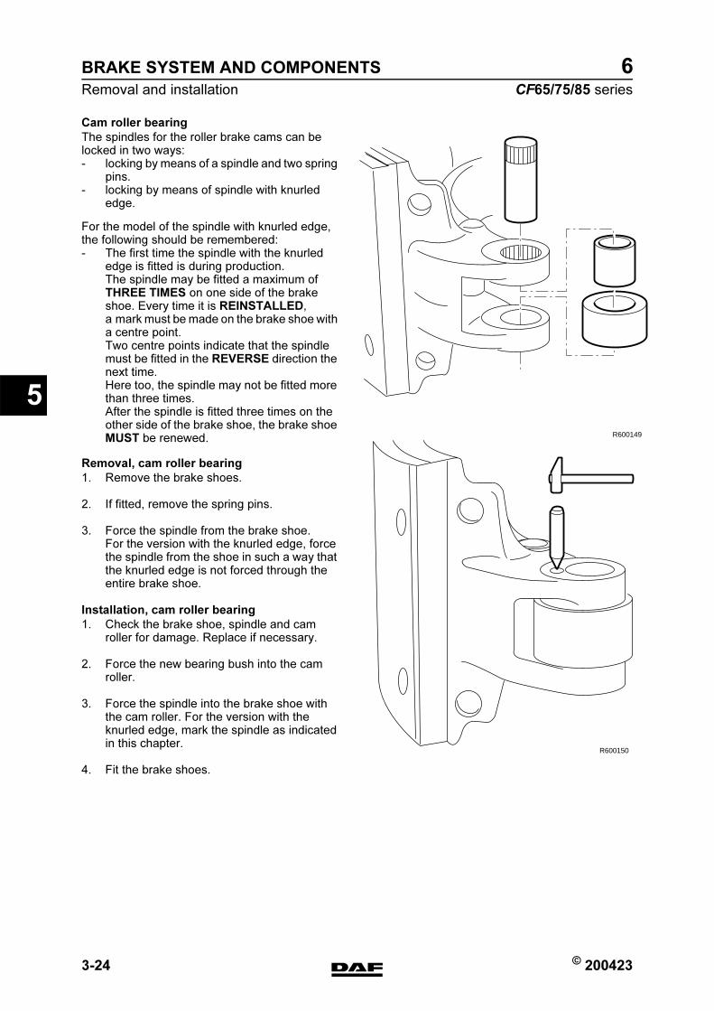
BRAKE SYSTEM AND COMPONENTS
3-24 © 200423
Removal and installation
5
ΧΦ65/75/85 series
6
Cam roller bearing
The spindles for the roller brake cams can be locked in two ways:- locking by means of a spindle and two spring
pins.- locking by means of spindle with knurled
edge.
For the model of the spindle with knurled edge, the following should be remembered:- The first time the spindle with the knurled
edge is fitted is during production.The spindle may be fitted a maximum of THREE TIMES on one side of the brake shoe. Every time it is REINSTALLED, a mark must be made on the brake shoe with a centre point.Two centre points indicate that the spindle must be fitted in the REVERSE direction the next time.Here too, the spindle may not be fitted more than three times.After the spindle is fitted three times on the other side of the brake shoe, the brake shoe MUST be renewed.
Removal, cam roller bearing
1. Remove the brake shoes.
2. If fitted, remove the spring pins.
3. Force the spindle from the brake shoe. For the version with the knurled edge, force the spindle from the shoe in such a way that the knurled edge is not forced through the entire brake shoe.
Installation, cam roller bearing
1. Check the brake shoe, spindle and cam roller for damage. Replace if necessary.
2. Force the new bearing bush into the cam roller.
3. Force the spindle into the brake shoe with the cam roller. For the version with the knurled edge, mark the spindle as indicated in this chapter.
4. Fit the brake shoes.
R600149
R600150
https://www.truck-manuals.net/
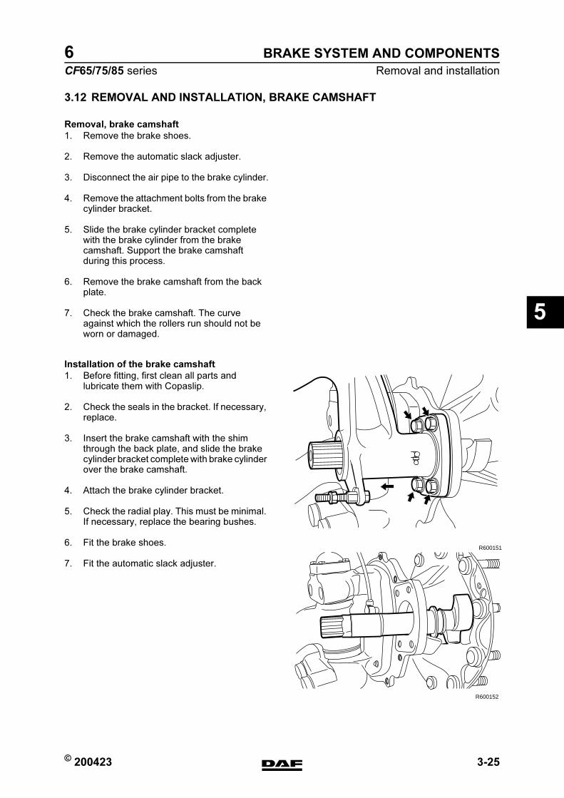
© 200423 3-25
Removal and installation
BRAKE SYSTEM AND COMPONENTS
ΧΦ65/75/85 series
6
5
3.12 REMOVAL AND INSTALLATION, BRAKE CAMSHAFT
Removal, brake camshaft
1. Remove the brake shoes.
2. Remove the automatic slack adjuster.
3. Disconnect the air pipe to the brake cylinder.
4. Remove the attachment bolts from the brake cylinder bracket.
5. Slide the brake cylinder bracket complete with the brake cylinder from the brake camshaft. Support the brake camshaft during this process.
6. Remove the brake camshaft from the back plate.
7. Check the brake camshaft. The curve against which the rollers run should not be worn or damaged.
Installation of the brake camshaft
1. Before fitting, first clean all parts and lubricate them with Copaslip.
2. Check the seals in the bracket. If necessary, replace.
3. Insert the brake camshaft with the shim through the back plate, and slide the brake cylinder bracket complete with brake cylinder over the brake camshaft.
4. Attach the brake cylinder bracket.
5. Check the radial play. This must be minimal. If necessary, replace the bearing bushes.
6. Fit the brake shoes.
7. Fit the automatic slack adjuster.
R600151
R600152
https://www.truck-manuals.net/
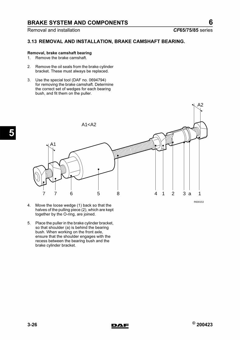
BRAKE SYSTEM AND COMPONENTS
3-26 © 200423
Removal and installation
5
ΧΦ65/75/85 series
6
3.13 REMOVAL AND INSTALLATION, BRAKE CAMSHAFT BEARING.
Removal, brake camshaft bearing
1. Remove the brake camshaft.
2. Remove the oil seals from the brake cylinder bracket. These must always be replaced.
3. Use the special tool (DAF no. 0694794) for removing the brake camshaft. Determine the correct set of wedges for each bearing bush, and fit them on the puller.
4. Move the loose wedge (1) back so that the halves of the pulling piece (2), which are kept together by the O-ring, are joined.
5. Place the puller in the brake cylinder bracket, so that shoulder (a) is behind the bearing bush. When working on the front axle, ensure that the shoulder engages with the recess between the bearing bush and the brake cylinder bracket.
R600153
7
A1
7 6 5 8 4 1 2 3 a 1
A2
A1<A2
https://www.truck-manuals.net/

© 200423 3-27
Removal and installation
BRAKE SYSTEM AND COMPONENTS
ΧΦ65/75/85 series
6
5
6. Using nut (4), screw the wedges as far as possible inwards. Tighten the nut finger-tight.
7. Place the spacer sleeve (5) against the brake cylinder bracket and screw nut (6) until the bearing bush is pulled out of the bracket.Ensure that the contact faces of nut (6), the spacer sleeve (5) and the threaded spindle (8) are sufficiently lubricated.
Installation, brake camshaft bearing
1. Check the brake cylinder bracket for damage. If necessary, replace.
2. Check whether the lubricating nipple is open, so that the bearings can be lubricated with grease from the automatic lubrication system.
3. Fit the bearing bushes using the special tool (DAF no. 1310421).
4. Check the brake camshaft for smooth operation. If necessary, ream the bushes. Play between spindle and bush 0.1 to 0.2 mm.
R600154
https://www.truck-manuals.net/
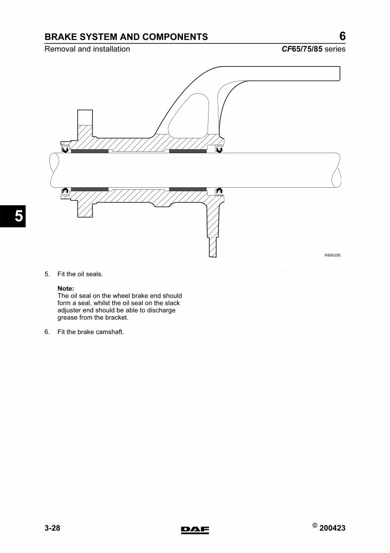
BRAKE SYSTEM AND COMPONENTS
3-28 © 200423
Removal and installation
5
ΧΦ65/75/85 series
6
5. Fit the oil seals.
Note:The oil seal on the wheel brake end should form a seal, whilst the oil seal on the slack adjuster end should be able to discharge grease from the bracket.
6. Fit the brake camshaft.
R600185
https://www.truck-manuals.net/
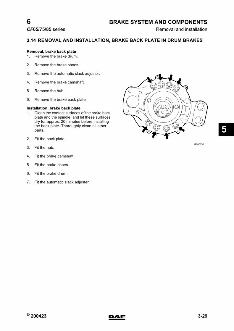
© 200423 3-29
Removal and installation
BRAKE SYSTEM AND COMPONENTS
ΧΦ65/75/85 series
6
5
3.14 REMOVAL AND INSTALLATION, BRAKE BACK PLATE IN DRUM BRAKES
Removal, brake back plate
1. Remove the brake drum.
2. Remove the brake shoes.
3. Remove the automatic slack adjuster.
4. Remove the brake camshaft.
5. Remove the hub.
6. Remove the brake back plate.
Installation, brake back plate
1. Clean the contact surfaces of the brake back plate and the spindle, and let these surfaces dry for approx. 20 minutes before installing the back plate. Thoroughly clean all other parts.
2. Fit the back plate.
3. Fit the hub.
4. Fit the brake camshaft.
5. Fit the brake shoes.
6. Fit the brake drum.
7. Fit the automatic slack adjuster.
R600156
https://www.truck-manuals.net/

BRAKE SYSTEM AND COMPONENTS
3-30 © 200423
Removal and installation
5
ΧΦ65/75/85 series
6
3.15 REMOVAL AND INSTALLATION, BRAKE BACK PLATE IN DISC BRAKES
Removal, brake back plate
1. Remove the brake calliper.
2. Remove the brake calliper carrier.
3. Remove the hub (and brake disc).
4. Remove the brake back plate.
Installation, brake back plate
1. Clean the contact surfaces of the brake back plate and the spindle, and let these surfaces dry for approx. 20 minutes before installing the back plate. Thoroughly clean all other parts.
2. Install the brake back plate and tighten the attachment bolts to the specified torque. See "Technical data".
3. Install the hub (and brake disc).
4. Fit the brake calliper carrier.
5. Fit the brake calliper.
https://www.truck-manuals.net/
© 200423 3-31
Removal and installation
BRAKE SYSTEM AND COMPONENTS
ΧΦ65/75/85 series
6
5
3.16 REMOVAL AND INSTALLATION, COMPRESSOR CYLINDER HEAD GASKET
Always replace the gaskets when carrying out repairs.
Removing the cylinder head gasket
1. Drain some of the coolant.
2. Remove the suction line.
3. Remove the delivery line.
4. Remove the coolant connections.
5. Remove the cylinder head bolts.
6. Remove the cylinder head assembly.
Installing the cylinder head gasket
1. Thoroughly clean all parts.
2. Check whether there are any remnants on the piston in the compressor.
3. Install the head gasket. Use studs if necessary to ease installation.
4. Install the valve housing including the inlet plates and spring plates.
5. Install the valve housing gasket and the cylinder head.
6. Install the cylinder head bolts and tighten to the specified torque, starting from the centre bolt. See "Technical data".
7. Install the suction line.
8. Install the delivery line.
9. Connect the coolant connections.
10. Fill the cooling system.
11. Check the operation of the compressor. See "Inspection and adjustment".
}
https://www.truck-manuals.net/
BRAKE SYSTEM AND COMPONENTS
3-32 © 200423
Removal and installation
5
ΧΦ65/75/85 series
6
3.17 REMOVAL AND INSTALLATION, AIR DRYER FILTER ELEMENT
Note:To be certain that the air dryer is functioning properly, the air reservoirs should regularly be checked for condensation.
If repeatedly more than the normal amount of water is drained off, the filter element will have to be replaced.
Under normal circumstances the element must be replaced at least once per year.
https://www.truck-manuals.net/

© 200423 3-33
Removal and installation
BRAKE SYSTEM AND COMPONENTS
ΧΦ65/75/85 series
6
5
Removing air dryer filter element
1. Bleed the air dryer by allowing it to regenerate or by loosening the compressor pipe (1), so that the interior of the air dryer is depressurised.
2. Remove the filter element by turning it anti-clockwise using a filter strap spanner.
3. The filter element should be disposed of as if it were an oil filter.
4. Clean the air dryer internally.
5. Check the air dryer threaded connection (2) for damage and then lubricate it sparingly with grease.
Installing the air dryer filter element
1. Lubricate the sealing ring of the new filter element sparingly with grease.
2. Fit the filter element by manually tightening it until the sealing ring abuts. Then tighten the filter element by hand (approx. 1 turn).
3. Fasten the compressor line (1).
4. Pressurise the system and then check the air dryer for air leaks.
5. Fill in the date on the sticker with a waterproof felt pen by which the filter element must be replaced (max. 1 year after fitting).
R600525
1
R600526
2
ArtikelnummerReference
TeilenummerRéférence
Eerstvolgende vervangingNext change
Nächster WechselProchain remplacement
1391510
R600523
https://www.truck-manuals.net/

BRAKE SYSTEM AND COMPONENTS
3-34 © 200423
Removal and installation
5
ΧΦ65/75/85 series
6
3.18 REMOVAL AND INSTALLATION, BRAKE PADS
Make sure no fingers get trapped between the brake calliper and the brake calliper carrier during and following removal of the brake pads. Always take hold of the brake calliper on the outside.
Removing the brake pads
1. Apply the parking brake.If the respective axle has spring brake cylinders, place chocks in front of and behind the wheels of another axle and release the parking brake.
2. Remove the wheels in question.
3. Remove the hairpin spring (26) and washer (45) from the yoke pin (44) of the locking strip (11).
4. Press the strip on and remove the yoke pin (44).
5. Check the strip for corrosion; replace if necessary.
6. Remove the sealing cap (37).
7. Using a ring spanner and the adapter, turn the hexagonal bolt (23) anti-clockwise until the brake pads (12) can be removed (a clicking noise can be heard).
Note:Never turn the hexagonal adjusting bolt without using an adapter. The adapter is a torque safety and will break off when the torque is too high. Without the use of an adapter the mechanics in the brake calliper may become damaged when the torque is too high, so that replacement of the brake calliper may be necessary.
8. Remove the brake pads.
Note:If the brake pads have wear end indicators, they must be removed at the same time as the brake pads, including accessories.
Installing the brake pads
1. Check the brake calliper play. See "Inspection and adjustment".
}
2645
11
44
R600461
1212
R600462
3723
https://www.truck-manuals.net/
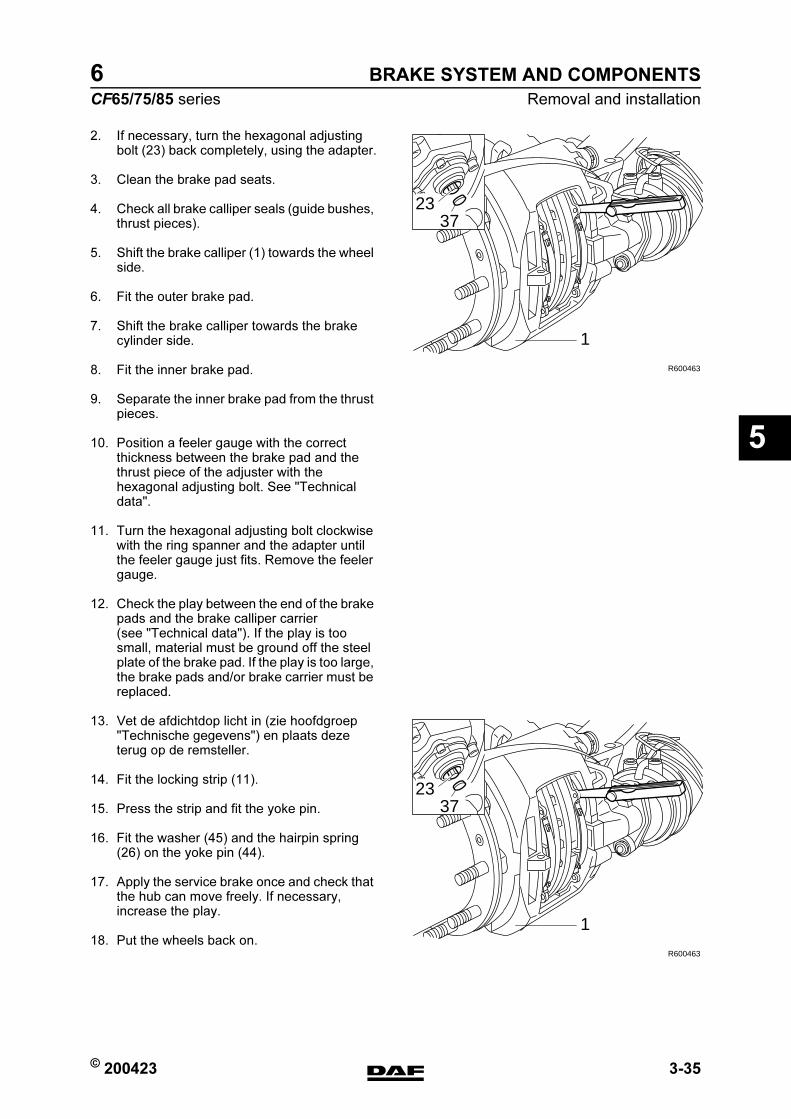
© 200423 3-35
Removal and installation
BRAKE SYSTEM AND COMPONENTS
ΧΦ65/75/85 series
6
5
2. If necessary, turn the hexagonal adjusting bolt (23) back completely, using the adapter.
3. Clean the brake pad seats.
4. Check all brake calliper seals (guide bushes, thrust pieces).
5. Shift the brake calliper (1) towards the wheel side.
6. Fit the outer brake pad.
7. Shift the brake calliper towards the brake cylinder side.
8. Fit the inner brake pad.
9. Separate the inner brake pad from the thrust pieces.
10. Position a feeler gauge with the correct thickness between the brake pad and the thrust piece of the adjuster with the hexagonal adjusting bolt. See "Technical data".
11. Turn the hexagonal adjusting bolt clockwise with the ring spanner and the adapter until the feeler gauge just fits. Remove the feeler gauge.
12. Check the play between the end of the brake pads and the brake calliper carrier (see "Technical data"). If the play is too small, material must be ground off the steel plate of the brake pad. If the play is too large, the brake pads and/or brake carrier must be replaced.
13. Vet de afdichtdop licht in (zie hoofdgroep "Technische gegevens") en plaats deze terug op de remsteller.
14. Fit the locking strip (11).
15. Press the strip and fit the yoke pin.
16. Fit the washer (45) and the hairpin spring (26) on the yoke pin (44).
17. Apply the service brake once and check that the hub can move freely. If necessary, increase the play.
18. Put the wheels back on.
2337
1
R600463
2337
1
R600463
https://www.truck-manuals.net/
BRAKE SYSTEM AND COMPONENTS
3-36 © 200423
Removal and installation
5
ΧΦ65/75/85 series
6
3.19 REMOVAL AND INSTALLATION, BRAKE DISC
Removal, brake disc
1. Remove the hub.
2. Remove the locking plates.
3. Remove the spring plates between the disc and hub and tap the disc from the hub using a copper hammer.If the disc does not come free from the hub, it can be removed by placing it on an old brake drum and pushing it off the hub using a press.
Installation, brake disc
1. Remove dirt and corrosion from the contact surfaces of the brake disc and hub.
2. Position the brake disc on the hub.
3. Fit the spring plates and tighten them to the specified torque. See "Technical data".
https://www.truck-manuals.net/
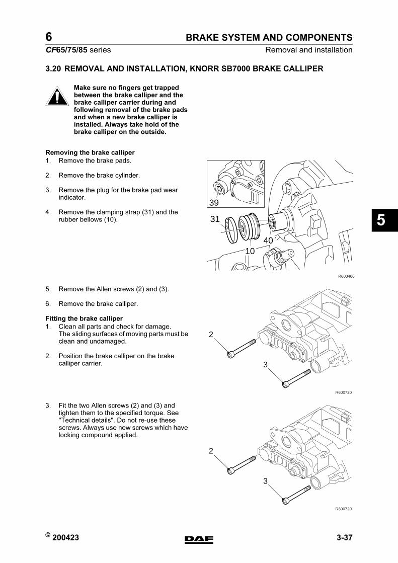
© 200423 3-37
Removal and installation
BRAKE SYSTEM AND COMPONENTS
ΧΦ65/75/85 series
6
5
3.20 REMOVAL AND INSTALLATION, KNORR SB7000 BRAKE CALLIPER
Make sure no fingers get trapped between the brake calliper and the brake calliper carrier during and following removal of the brake pads and when a new brake calliper is installed. Always take hold of the brake calliper on the outside.
Removing the brake calliper
1. Remove the brake pads.
2. Remove the brake cylinder.
3. Remove the plug for the brake pad wear indicator.
4. Remove the clamping strap (31) and the rubber bellows (10).
5. Remove the Allen screws (2) and (3).
6. Remove the brake calliper.
Fitting the brake calliper
1. Clean all parts and check for damage. The sliding surfaces of moving parts must be clean and undamaged.
2. Position the brake calliper on the brake calliper carrier.
3. Fit the two Allen screws (2) and (3) and tighten them to the specified torque. See "Technical details". Do not re-use these screws. Always use new screws which have locking compound applied.
}
31
39
R600466
1040
2
3
R600720
2
3
R600720
https://www.truck-manuals.net/
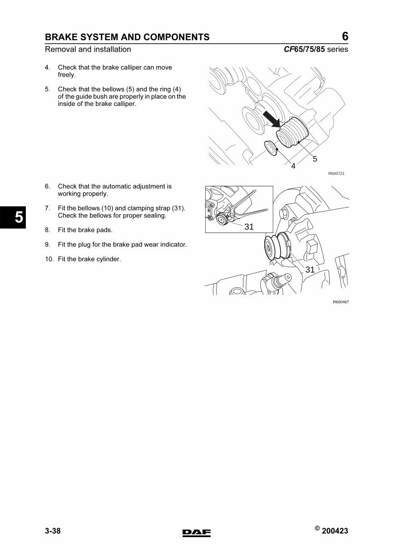
BRAKE SYSTEM AND COMPONENTS
3-38 © 200423
Removal and installation
5
ΧΦ65/75/85 series
6
4. Check that the brake calliper can move freely.
5. Check that the bellows (5) and the ring (4) of the guide bush are properly in place on the inside of the brake calliper.
6. Check that the automatic adjustment is working properly.
7. Fit the bellows (10) and clamping strap (31). Check the bellows for proper sealing.
8. Fit the brake pads.
9. Fit the plug for the brake pad wear indicator.
10. Fit the brake cylinder.
R600721
54
39 31
R600467
31
https://www.truck-manuals.net/
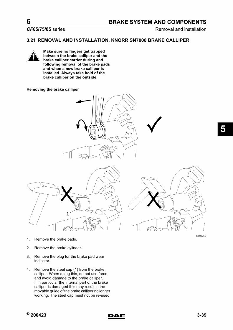
© 200423 3-39
Removal and installation
BRAKE SYSTEM AND COMPONENTS
ΧΦ65/75/85 series
6
5
3.21 REMOVAL AND INSTALLATION, KNORR SN7000 BRAKE CALLIPER
Make sure no fingers get trapped between the brake calliper and the brake calliper carrier during and following removal of the brake pads and when a new brake calliper is installed. Always take hold of the brake calliper on the outside.
Removing the brake calliper
1. Remove the brake pads.
2. Remove the brake cylinder.
3. Remove the plug for the brake pad wear indicator.
4. Remove the steel cap (1) from the brake calliper. When doing this, do not use force and avoid damage to the brake calliper. If in particular the internal part of the brake calliper is damaged this may result in the movable guide of the brake calliper no longer working. The steel cap must not be re-used.
}
R600765
1
https://www.truck-manuals.net/

BRAKE SYSTEM AND COMPONENTS
3-40 © 200423
Removal and installation
5
ΧΦ65/75/85 series
6
5. Remove the Allen screws (2) and (3).
6. Remove the brake calliper.
Fitting the brake calliper
1. Clean all parts and check for damage. The sliding surfaces of moving parts must be clean and undamaged.
2. Make sure that the guide pin in the bronze bearing bush is positioned in such a way that the rubber bellows is compressed on the inside.
3. Position the brake calliper on the brake calliper carrier.
4. Fit the two Allen screws (2) and (3) and tighten them to the specified torque. See "Technical details". Never re-use these screws. Always use new screws which have locking compound applied.
5. Check that the brake calliper can move freely.
6. Check that the bellows (5) and the ring (4) of the guide bush are properly in place on the inside of the brake calliper.
7. Check that the automatic adjustment is working properly.
2
3
R600720
R600721
54
https://www.truck-manuals.net/

© 200423 3-41
Removal and installation
BRAKE SYSTEM AND COMPONENTS
ΧΦ65/75/85 series
6
5
8. Assemble a punch from the special tool set (DAF no. 1329495) by means of T2 (only the handle) and T17.
9. Clean the bore in the brake calliper and manually fit a new, clean steel cap (1).
10. Slide the press-in tool (2), special tool (DAF no. 1453140), over the steel cap.
11. Using a hammer and the assembled punch, knock the steel cap as far as the stop in the brake calliper.
12. Fit the brake pads.
13. Fit the plug for the brake pad wear indicator.
14. Fit the brake cylinder.
R600766
31T17
T17
T2
T17 1 2 3
12
2
https://www.truck-manuals.net/
BRAKE SYSTEM AND COMPONENTS
3-42 © 200423
Removal and installation
5
ΧΦ65/75/85 series
6
3.22 REMOVAL AND INSTALLATION, BRAKE CALLIPER CARRIER
Removing brake calliper carrier
1. Remove the brake calliper.
2. Remove the attachment bolts from the brake calliper carrier.
3. Remove the brake calliper carrier.
Fitting the brake calliper carrier
1. Clean the brake calliper carrier and the contact surfaces of the stub axle or brake back plate. Pay particular attention to the threaded holes and sliding surfaces of the brake pads.
2. Fit the brake calliper carrier against the stub axle or brake back plate.
3. Fit the attachment bolts and tighten to the specified torque. See "Technical data".
Note:Starting in production week 2002-25, the attachment of the brake calliper against the stub axle (front axles) may have been changed on models with disc brakes. Five bolts are now used instead of six bolts. The bolt hole for the "6th bolt" is then still fitted in the brake calliper carrier, but not in the stub axle.
https://www.truck-manuals.net/
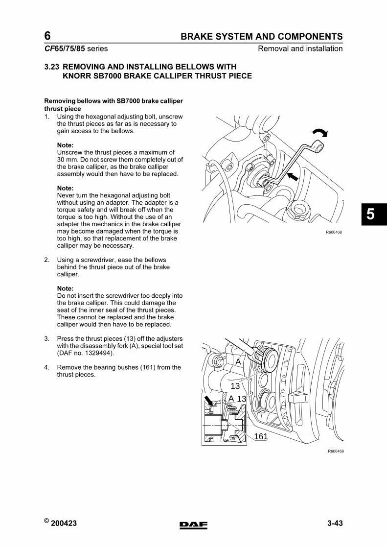
© 200423 3-43
Removal and installation
BRAKE SYSTEM AND COMPONENTS
ΧΦ65/75/85 series
6
5
3.23 REMOVING AND INSTALLING BELLOWS WITH
KNORR SB7000 BRAKE CALLIPER THRUST PIECE
Removing bellows with SB7000 brake calliper
thrust piece
1. Using the hexagonal adjusting bolt, unscrew the thrust pieces as far as is necessary to gain access to the bellows.
Note:Unscrew the thrust pieces a maximum of 30 mm. Do not screw them completely out of the brake calliper, as the brake calliper assembly would then have to be replaced.
Note:Never turn the hexagonal adjusting bolt without using an adapter. The adapter is a torque safety and will break off when the torque is too high. Without the use of an adapter the mechanics in the brake calliper may become damaged when the torque is too high, so that replacement of the brake calliper may be necessary.
2. Using a screwdriver, ease the bellows behind the thrust piece out of the brake calliper.
Note:Do not insert the screwdriver too deeply into the brake calliper. This could damage the seat of the inner seal of the thrust pieces. These cannot be replaced and the brake calliper would then have to be replaced.
3. Press the thrust pieces (13) off the adjusters with the disassembly fork (A), special tool set (DAF no. 1329494).
4. Remove the bearing bushes (161) from the thrust pieces.
R600468
A 13
13
R600469
161
A
https://www.truck-manuals.net/
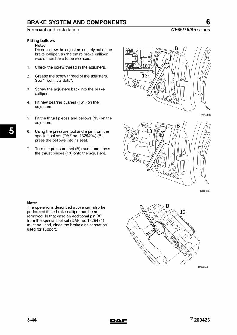
BRAKE SYSTEM AND COMPONENTS
3-44 © 200423
Removal and installation
5
ΧΦ65/75/85 series
6
Fitting bellows
Note:Do not screw the adjusters entirely out of the brake calliper, as the entire brake calliper would then have to be replaced.
1. Check the screw thread in the adjusters.
2. Grease the screw thread of the adjusters. See "Technical data".
3. Screw the adjusters back into the brake calliper.
4. Fit new bearing bushes (161) on the adjusters.
5. Fit the thrust pieces and bellows (13) on the adjusters.
6. Using the pressure tool and a pin from the special tool set (DAF no. 1329494) (B), press the bellows into its seat.
7. Turn the pressure tool (B) round and press the thrust pieces (13) onto the adjusters.
Note:The operations described above can also be performed if the brake calliper has been removed. In that case an additional pin (8) from the special tool set (DAF no. 1329494) must be used, since the brake disc cannot be used for support.
B
13
161
R600470
B13
R600465
B13
R600464
https://www.truck-manuals.net/
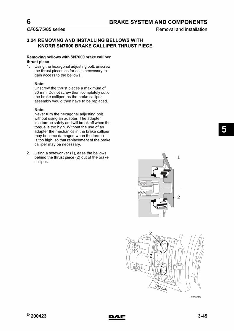
© 200423 3-45
Removal and installation
BRAKE SYSTEM AND COMPONENTS
ΧΦ65/75/85 series
6
5
3.24 REMOVING AND INSTALLING BELLOWS WITH
KNORR SN7000 BRAKE CALLIPER THRUST PIECE
Removing bellows with SN7000 brake calliper
thrust piece
1. Using the hexagonal adjusting bolt, unscrew the thrust pieces as far as is necessary to gain access to the bellows.
Note:Unscrew the thrust pieces a maximum of 30 mm. Do not screw them completely out of the brake calliper, as the brake calliper assembly would then have to be replaced.
Note:Never turn the hexagonal adjusting bolt without using an adapter. The adapter is a torque safety and will break off when the torque is too high. Without the use of an adapter the mechanics in the brake calliper may become damaged when the torque is too high, so that replacement of the brake calliper may be necessary.
2. Using a screwdriver (1), ease the bellows behind the thrust piece (2) out of the brake calliper.
30 mm
2
2
1
2
R600713
https://www.truck-manuals.net/
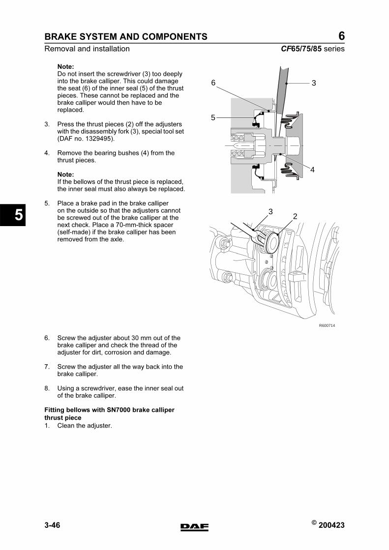
BRAKE SYSTEM AND COMPONENTS
3-46 © 200423
Removal and installation
5
ΧΦ65/75/85 series
6
Note:Do not insert the screwdriver (3) too deeply into the brake calliper. This could damage the seat (6) of the inner seal (5) of the thrust pieces. These cannot be replaced and the brake calliper would then have to be replaced.
3. Press the thrust pieces (2) off the adjusters with the disassembly fork (3), special tool set (DAF no. 1329495).
4. Remove the bearing bushes (4) from the thrust pieces.
Note:If the bellows of the thrust piece is replaced, the inner seal must also always be replaced.
5. Place a brake pad in the brake calliper on the outside so that the adjusters cannot be screwed out of the brake calliper at the next check. Place a 70-mm-thick spacer (self-made) if the brake calliper has been removed from the axle.
6. Screw the adjuster about 30 mm out of the brake calliper and check the thread of the adjuster for dirt, corrosion and damage.
7. Screw the adjuster all the way back into the brake calliper.
8. Using a screwdriver, ease the inner seal out of the brake calliper.
Fitting bellows with SN7000 brake calliper
thrust piece
1. Clean the adjuster.
R600714
23
3
5
6
4
https://www.truck-manuals.net/
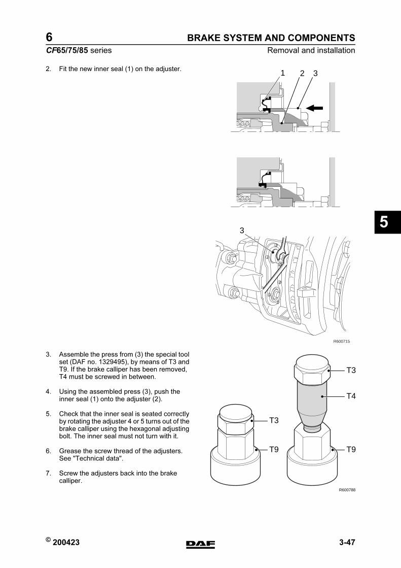
© 200423 3-47
Removal and installation
BRAKE SYSTEM AND COMPONENTS
ΧΦ65/75/85 series
6
5
2. Fit the new inner seal (1) on the adjuster.
3. Assemble the press from (3) the special tool set (DAF no. 1329495), by means of T3 and T9. If the brake calliper has been removed, T4 must be screwed in between.
4. Using the assembled press (3), push the inner seal (1) onto the adjuster (2).
5. Check that the inner seal is seated correctly by rotating the adjuster 4 or 5 turns out of the brake calliper using the hexagonal adjusting bolt. The inner seal must not turn with it.
6. Grease the screw thread of the adjusters. See "Technical data".
7. Screw the adjusters back into the brake calliper.
R600715
3
321
T9
R600788
T4
T3
T9
T3
https://www.truck-manuals.net/
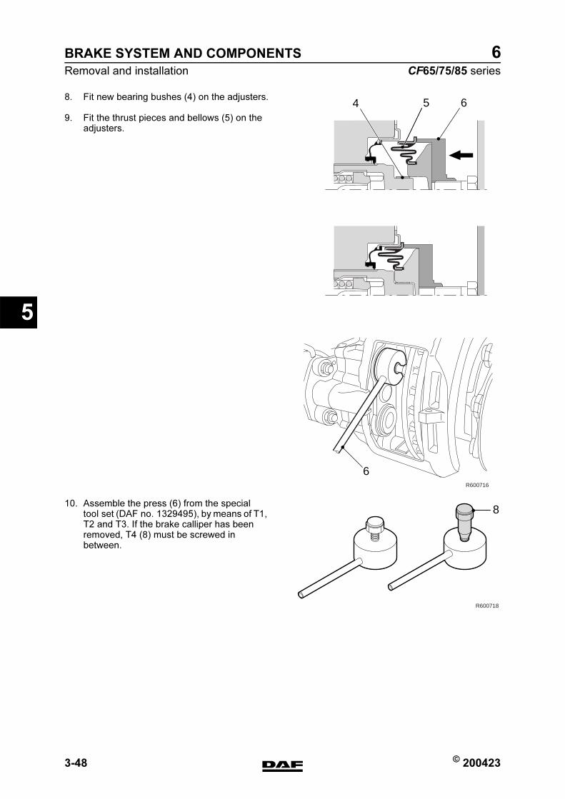
BRAKE SYSTEM AND COMPONENTS
3-48 © 200423
Removal and installation
5
ΧΦ65/75/85 series
6
8. Fit new bearing bushes (4) on the adjusters.
9. Fit the thrust pieces and bellows (5) on the adjusters.
10. Assemble the press (6) from the special tool set (DAF no. 1329495), by means of T1, T2 and T3. If the brake calliper has been removed, T4 (8) must be screwed in between.
R600716
654
6
R600718
8
https://www.truck-manuals.net/

© 200423 3-49
Removal and installation
BRAKE SYSTEM AND COMPONENTS
ΧΦ65/75/85 series
6
5
11. Using the pressure tool (6), push the bellows (5) into its seat.
12. Turn the pressure tool (6) round and press the thrust pieces (7) onto the adjusters.
R600717
7 6
https://www.truck-manuals.net/
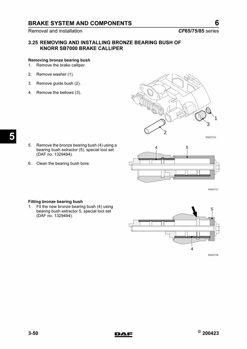
BRAKE SYSTEM AND COMPONENTS
3-50 © 200423
Removal and installation
5
ΧΦ65/75/85 series
6
3.25 REMOVING AND INSTALLING BRONZE BEARING BUSH OF
KNORR SB7000 BRAKE CALLIPER
Removing bronze bearing bush
1. Remove the brake calliper.
2. Remove washer (1).
3. Remove guide bush (2).
4. Remove the bellows (3).
5. Remove the bronze bearing bush (4) using a bearing bush extractor (5), special tool set (DAF no. 1329494).
6. Clean the bearing bush bore.
Fitting bronze bearing bush
1. Fit the new bronze bearing bush (4) using bearing bush extractor 5, special tool set (DAF no. 1329494).
2
31
R600723
R600727
4 5
R600728
4
5
https://www.truck-manuals.net/
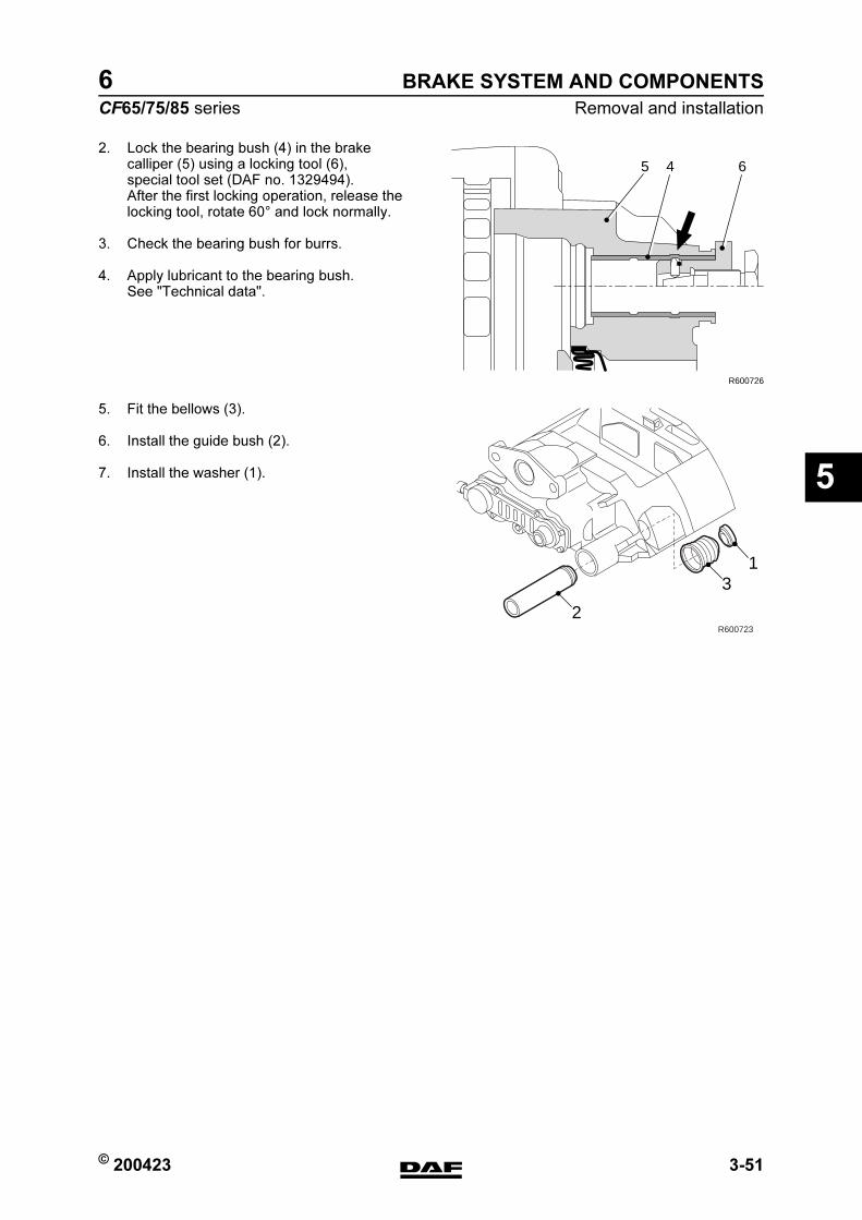
© 200423 3-51
Removal and installation
BRAKE SYSTEM AND COMPONENTS
ΧΦ65/75/85 series
6
5
2. Lock the bearing bush (4) in the brake calliper (5) using a locking tool (6), special tool set (DAF no. 1329494).After the first locking operation, release the locking tool, rotate 60 and lock normally.
3. Check the bearing bush for burrs.
4. Apply lubricant to the bearing bush. See "Technical data".
5. Fit the bellows (3).
6. Install the guide bush (2).
7. Install the washer (1).
65 4
R600726
2
31
R600723
https://www.truck-manuals.net/
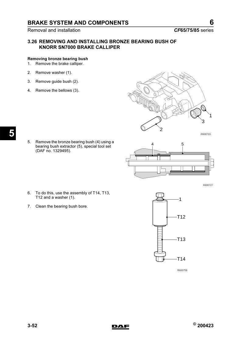
BRAKE SYSTEM AND COMPONENTS
3-52 © 200423
Removal and installation
5
ΧΦ65/75/85 series
6
3.26 REMOVING AND INSTALLING BRONZE BEARING BUSH OF
KNORR SN7000 BRAKE CALLIPER
Removing bronze bearing bush
1. Remove the brake calliper.
2. Remove washer (1).
3. Remove guide bush (2).
4. Remove the bellows (3).
5. Remove the bronze bearing bush (4) using a bearing bush extractor (5), special tool set (DAF no. 1329495).
6. To do this, use the assembly of T14, T13, T12 and a washer (1).
7. Clean the bearing bush bore.
2
31
R600723
R600727
4 5
T12
T13
T14
R600759
1
https://www.truck-manuals.net/

© 200423 3-53
Removal and installation
BRAKE SYSTEM AND COMPONENTS
ΧΦ65/75/85 series
6
5
Fitting bronze bearing bush
1. Fit the new bronze bearing bush (4) using bearing bush extractor (5), special tool set (DAF no. 1329495).
2. To do this, use the assembly of T16, T13, T8, T14 and a washer (1).
R600728
4
5
1
T14
T8
T13
T16
R600760
https://www.truck-manuals.net/

BRAKE SYSTEM AND COMPONENTS
3-54 © 200423
Removal and installation
5
ΧΦ65/75/85 series
6
3. Tighten the brass nut (T14) of the bearing bush extractor (D) as far as the stop so as to push in the bronze bush (7) (a, b). Then tighten the steel bolt of T16 as far as the stop so as to lock the bronze bush (c). Loosen the steel bolt of T16 by 20 mm axially, rotate the tool T16 by 60 and tighten the steel bolt of T16 as far as the stop (c). Remove the bearing bush extractor (D).
4. Check the bearing bush for burrs.
5. Apply lubricant to the bearing bush. See "Technical data".
6. Fit the bellows (3).
7. Install the guide bush (2).
8. Install the washer (1).
R600758
D
ba c
7
D
7
D
7
2
31
R600723
https://www.truck-manuals.net/
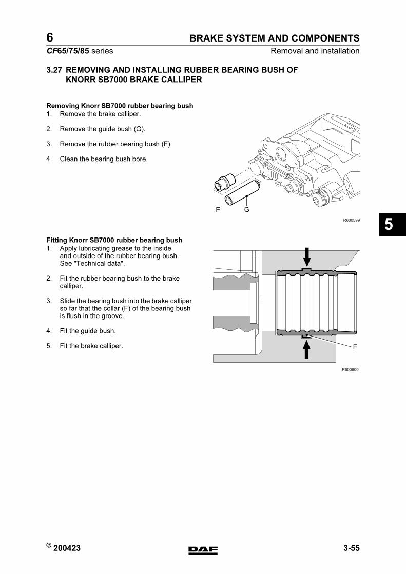
© 200423 3-55
Removal and installation
BRAKE SYSTEM AND COMPONENTS
ΧΦ65/75/85 series
6
5
3.27 REMOVING AND INSTALLING RUBBER BEARING BUSH OF
KNORR SB7000 BRAKE CALLIPER
Removing Knorr SB7000 rubber bearing bush
1. Remove the brake calliper.
2. Remove the guide bush (G).
3. Remove the rubber bearing bush (F).
4. Clean the bearing bush bore.
Fitting Knorr SB7000 rubber bearing bush
1. Apply lubricating grease to the inside and outside of the rubber bearing bush. See "Technical data".
2. Fit the rubber bearing bush to the brake calliper.
3. Slide the bearing bush into the brake calliper so far that the collar (F) of the bearing bush is flush in the groove.
4. Fit the guide bush.
5. Fit the brake calliper.
GR600599
F
R600600
F
https://www.truck-manuals.net/

BRAKE SYSTEM AND COMPONENTS
3-56 © 200423
Removal and installation
5
ΧΦ65/75/85 series
6
3.28 REMOVING AND INSTALLING RUBBER BEARING BUSH OF
KNORR SN7000 BRAKE CALLIPER
Removing Knorr SN7000 rubber bearing bush
1. Remove the brake calliper.
2. Remove the guide bush.
3. Clean the bearing bush and the bearing bush bore.
4. Assemble the press-out tool from the special tool set (DAF no. 1329495) by means of parts T22, T6, T20, T21 and a washer (1).
5. Using the press-out tool (1), push the bearing bush out of the brake calliper by retaining T22 and screwing T20 in.
Fitting Knorr SN7000 rubber bearing bush
1. Clean the bearing bore in the brake calliper and, if necessary, protect the surface against corrosion by means of zinc spray.
R600763
1
T21
T20
T6
T22
1
R600729
https://www.truck-manuals.net/

© 200423 3-57
Removal and installation
BRAKE SYSTEM AND COMPONENTS
ΧΦ65/75/85 series
6
5
2. Assemble the press-in tool from the special tool set (DAF no. 1329495) by means of parts T22, T19, T20, T18 and a washer (1).
3. Fit the rubber bearing bush (2) on the press-in tool (1) and push the bearing bush into the brake calliper. Hand-tighten T22. Make sure that the press-in tool is vertical on the contact surface (A) of the brake calliper by adjusting the small socket head screw (3).
4. Push the rubber bearing bush in using T20 and retain T22 with a spanner. Tighten T20 to the specified torque. See "Technical data". If the required tightening torque is higher or lower than the specified value, the brake calliper must be replaced.
5. Check that the metal outer ring of the bearing bush is secure in the brake calliper.
6. Apply lubricating grease in the bearing bush. See "Technical data".
7. Fit the guide bush.
8. Fit the brake calliper.
R600762
1
T18T20
T19
T22
R600764
A
3
1
2
https://www.truck-manuals.net/
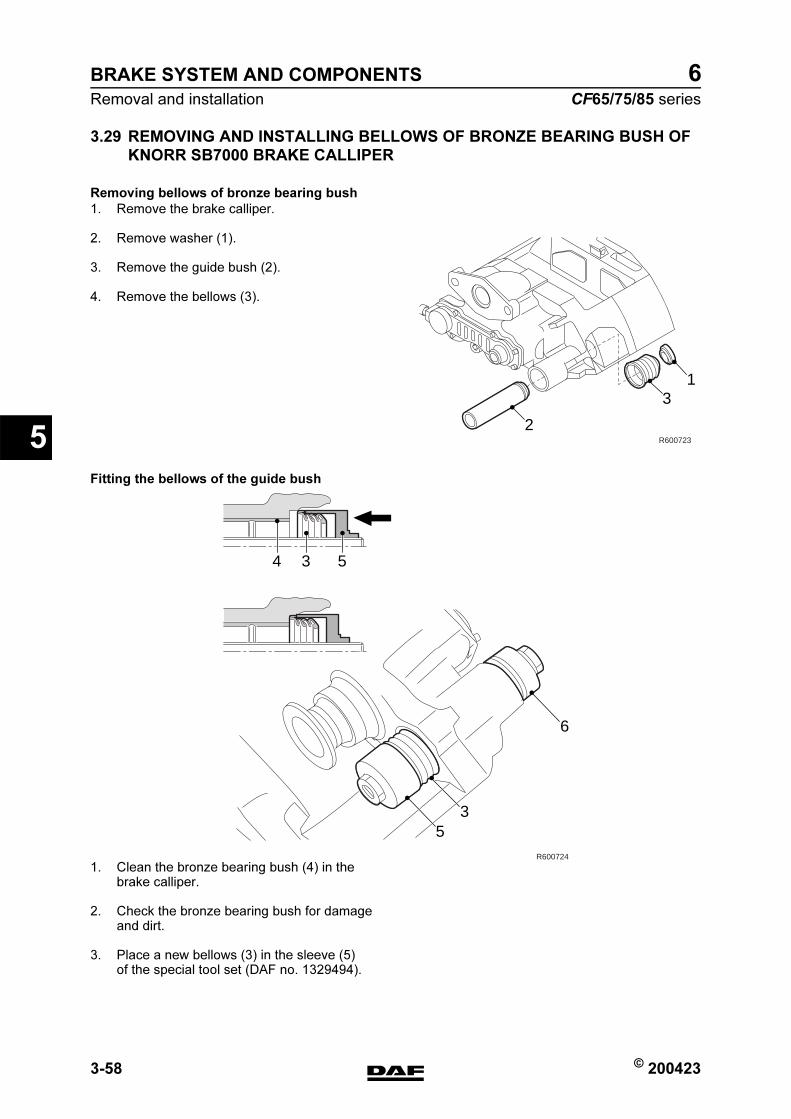
BRAKE SYSTEM AND COMPONENTS
3-58 © 200423
Removal and installation
5
ΧΦ65/75/85 series
6
3.29 REMOVING AND INSTALLING BELLOWS OF BRONZE BEARING BUSH OF
KNORR SB7000 BRAKE CALLIPER
Removing bellows of bronze bearing bush
1. Remove the brake calliper.
2. Remove washer (1).
3. Remove the guide bush (2).
4. Remove the bellows (3).
Fitting the bellows of the guide bush
1. Clean the bronze bearing bush (4) in the brake calliper.
2. Check the bronze bearing bush for damage and dirt.
3. Place a new bellows (3) in the sleeve (5) of the special tool set (DAF no. 1329494).
2
31
R600723
534
53
6
R600724
https://www.truck-manuals.net/

© 200423 3-59
Removal and installation
BRAKE SYSTEM AND COMPONENTS
ΧΦ65/75/85 series
6
5
4. Place the special tool and bellows in the bore of the brake calliper. Hand-tighten the press (6).
5. Push the bellows into the brake calliper by turning the press bolt clockwise. Remove the press.
6. Check the bellows fastening by pulling it outwards by hand. Damage is not permitted.
7. Apply lubricating grease to the bronze bearing bush and guide bush. See "Technical data".
8. Install the guide bush (2).
9. Install the washer (1).
10. Check that the guide bush moves freely in the brake calliper.
11. Fit the brake calliper.
R600725
2
31
R600723
https://www.truck-manuals.net/
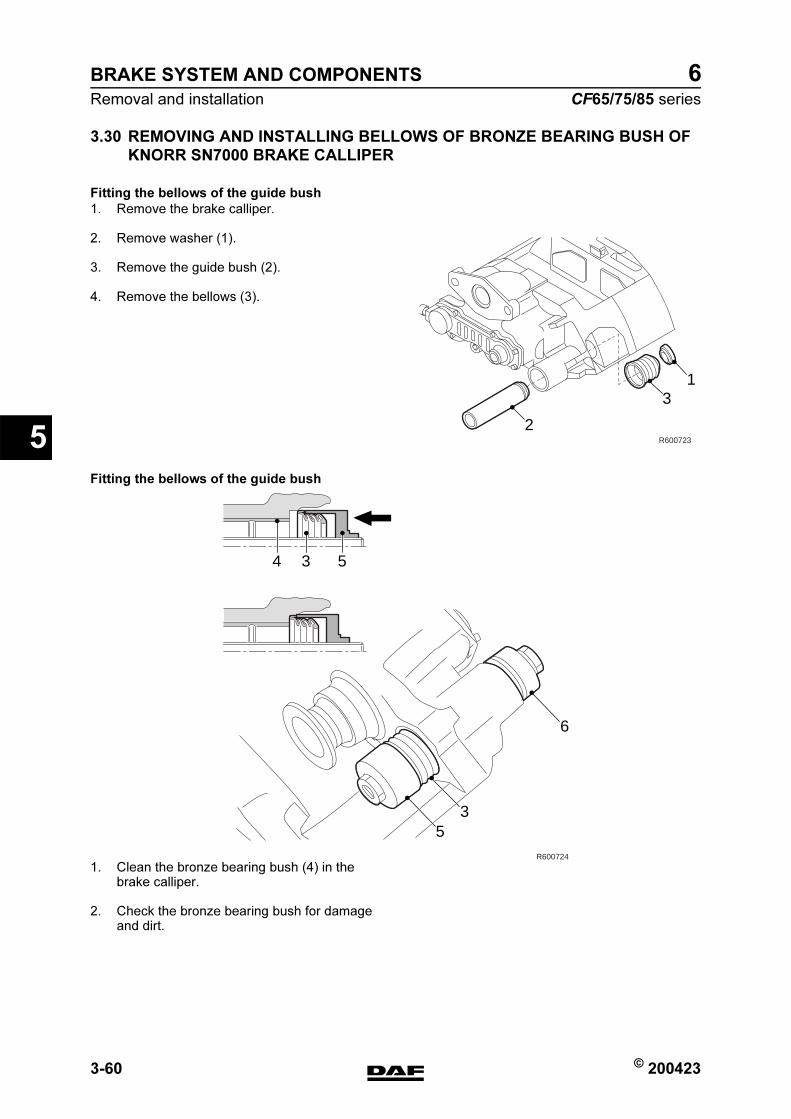
BRAKE SYSTEM AND COMPONENTS
3-60 © 200423
Removal and installation
5
ΧΦ65/75/85 series
6
3.30 REMOVING AND INSTALLING BELLOWS OF BRONZE BEARING BUSH OF
KNORR SN7000 BRAKE CALLIPER
Fitting the bellows of the guide bush
1. Remove the brake calliper.
2. Remove washer (1).
3. Remove the guide bush (2).
4. Remove the bellows (3).
Fitting the bellows of the guide bush
1. Clean the bronze bearing bush (4) in the brake calliper.
2. Check the bronze bearing bush for damage and dirt.
2
31
R600723
534
53
6
R600724
https://www.truck-manuals.net/

© 200423 3-61
Removal and installation
BRAKE SYSTEM AND COMPONENTS
ΧΦ65/75/85 series
6
5
3. Assemble a press from the special tool set (DAF no. 1329495). To do this, use T7, T10, T8 and a washer.
4. Place a new bellows (3) in the sleeve (5) of the assembled press.
5. Place the press and bellows in the bore of the brake calliper. Hand-tighten the press (6).
6. Tighten the press (6) to the specified torque. See "Technical data". Remove the press.
1
T8
T10
T7
R600761
534
53
6
R600724
https://www.truck-manuals.net/
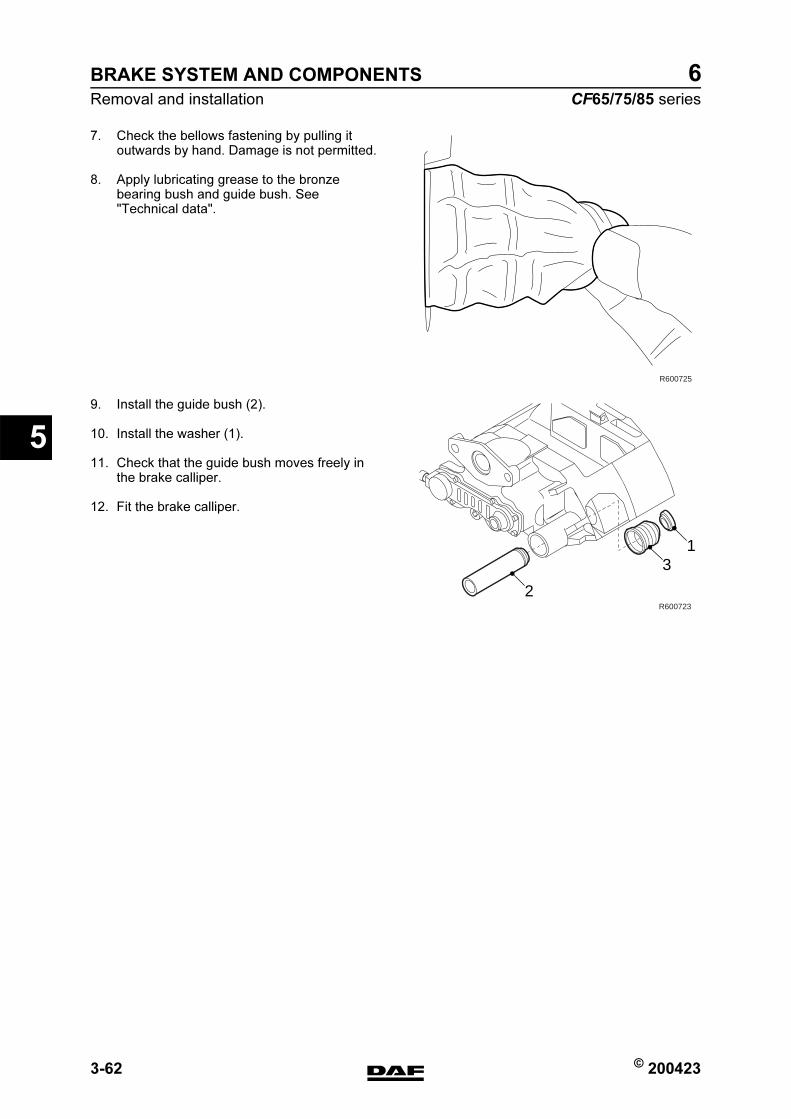
BRAKE SYSTEM AND COMPONENTS
3-62 © 200423
Removal and installation
5
ΧΦ65/75/85 series
6
7. Check the bellows fastening by pulling it outwards by hand. Damage is not permitted.
8. Apply lubricating grease to the bronze bearing bush and guide bush. See "Technical data".
9. Install the guide bush (2).
10. Install the washer (1).
11. Check that the guide bush moves freely in the brake calliper.
12. Fit the brake calliper.
R600725
2
31
R600723
https://www.truck-manuals.net/
© 200423 4-1
Disassembly and assembly
BRAKE SYSTEM AND COMPONENTS
ΧΦ65/75/85 series
6
5
4. DISASSEMBLY AND ASSEMBLY
4.1 DISASSEMBLY AND ASSEMBLY, BRAKE CHAMBER
Removal, diaphragm
1. Turn the brakes back until the spring in the brake chamber is under tension.
2. Mark the position of the brake chamber halves in relation to one another.
3. Remove the clamping strap from the brake chamber.
4. Remove the rear half of the brake chamber and the diaphragm.
Installation, diaphragm
1. Fit the new diaphragm and brake chamber half. (Pay attention to the markings or the small drainage hole.)
2. Fit the clamping strap.
3. Adjust the brakes. See "Inspection and adjustment".
4. Check the complete brake chamber for air leaks.
Disassembling the brake chamber
1. Remove the yoke and the lock nut from the push rod.
2. Slide a sealing ring and a piece of pipe over the push rod.
3. Screw the lock nut onto the push rod until the spring in the brake chamber is slightly tensed.
4. Mark the position of the brake chamber halves in relation to one another.
5. Loosen the clamping strap and remove the brake chamber half, the push rod and the diaphragm.
Assembly, brake chamber
1. Thoroughly clean all parts.
2. Check all parts for damage and replace them if necessary.
3. Replace the diaphragm in any case. Fit in the reverse order to removal.
https://www.truck-manuals.net/
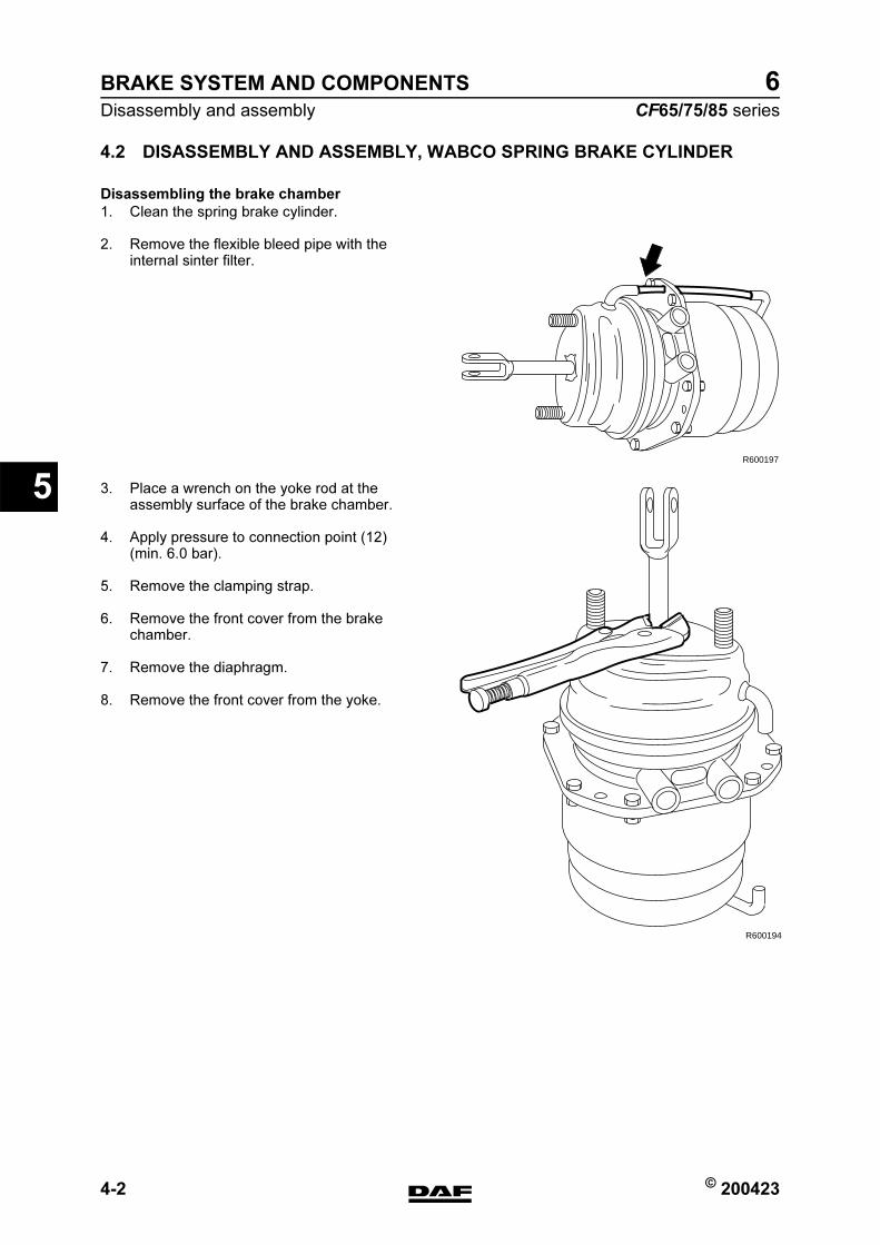
BRAKE SYSTEM AND COMPONENTS
4-2 © 200423
Disassembly and assembly
5
ΧΦ65/75/85 series
6
4.2 DISASSEMBLY AND ASSEMBLY, WABCO SPRING BRAKE CYLINDER
Disassembling the brake chamber
1. Clean the spring brake cylinder.
2. Remove the flexible bleed pipe with the internal sinter filter.
3. Place a wrench on the yoke rod at the assembly surface of the brake chamber.
4. Apply pressure to connection point (12) (min. 6.0 bar).
5. Remove the clamping strap.
6. Remove the front cover from the brake chamber.
7. Remove the diaphragm.
8. Remove the front cover from the yoke.
R600197
R600194
https://www.truck-manuals.net/
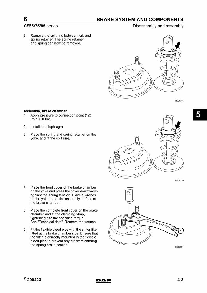
© 200423 4-3
Disassembly and assembly
BRAKE SYSTEM AND COMPONENTS
ΧΦ65/75/85 series
6
5
9. Remove the split ring between fork and spring retainer. The spring retainer and spring can now be removed.
Assembly, brake chamber
1. Apply pressure to connection point (12) (min. 6.0 bar).
2. Install the diaphragm.
3. Place the spring and spring retainer on the yoke, and fit the split ring.
4. Place the front cover of the brake chamber on the yoke and press the cover downwards against the spring tension. Place a wrench on the yoke rod at the assembly surface of the brake chamber.
5. Place the complete front cover on the brake chamber and fit the clamping strap, tightening it to the specified torque. See "Technical data". Remove the wrench.
6. Fit the flexible bleed pipe with the sinter filter fitted at the brake chamber side. Ensure that the filter is correctly mounted in the flexible bleed pipe to prevent any dirt from entering the spring brake section.
R600195
R600195
R600196
https://www.truck-manuals.net/
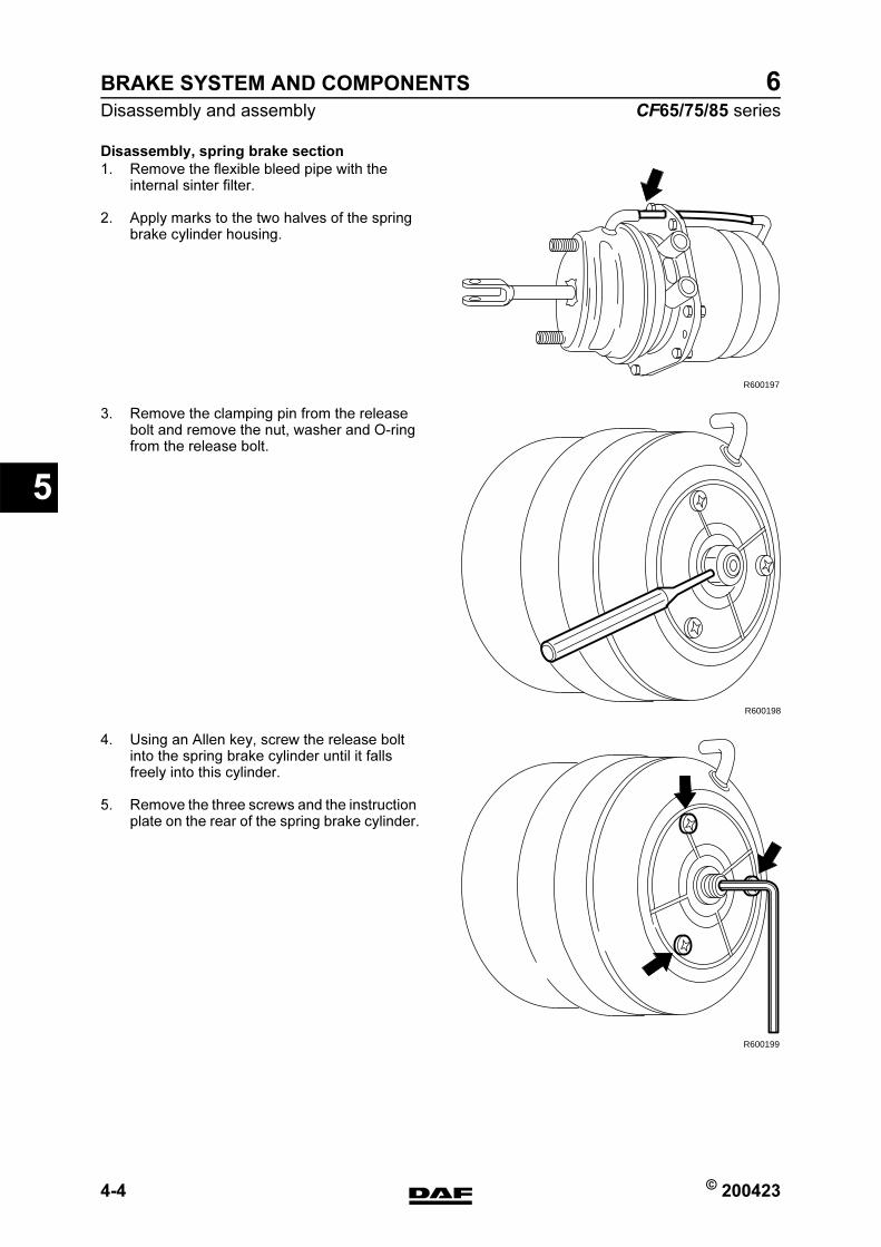
BRAKE SYSTEM AND COMPONENTS
4-4 © 200423
Disassembly and assembly
5
ΧΦ65/75/85 series
6
Disassembly, spring brake section
1. Remove the flexible bleed pipe with the internal sinter filter.
2. Apply marks to the two halves of the spring brake cylinder housing.
3. Remove the clamping pin from the release bolt and remove the nut, washer and O-ring from the release bolt.
4. Using an Allen key, screw the release bolt into the spring brake cylinder until it falls freely into this cylinder.
5. Remove the three screws and the instruction plate on the rear of the spring brake cylinder.
R600197
R600198
R600199
https://www.truck-manuals.net/
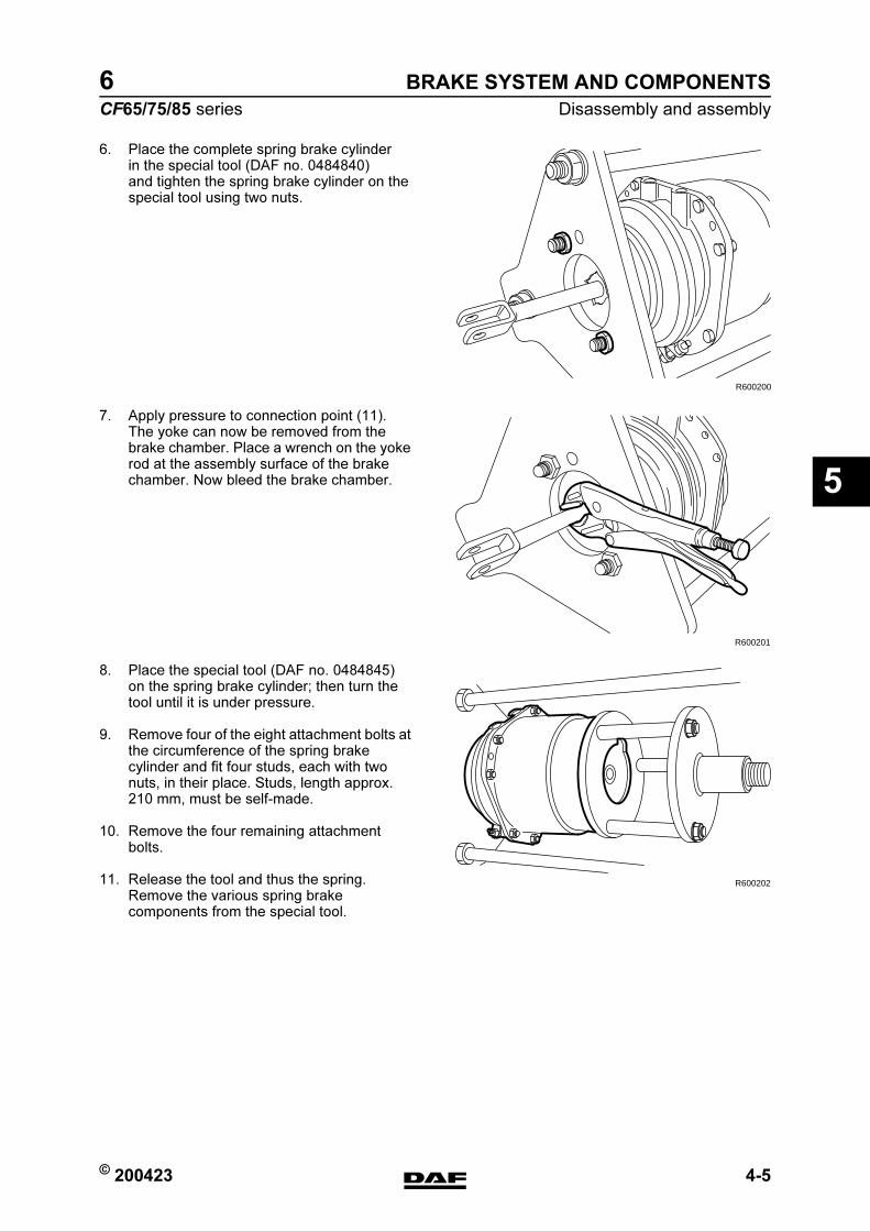
© 200423 4-5
Disassembly and assembly
BRAKE SYSTEM AND COMPONENTS
ΧΦ65/75/85 series
6
5
6. Place the complete spring brake cylinder in the special tool (DAF no. 0484840) and tighten the spring brake cylinder on the special tool using two nuts.
7. Apply pressure to connection point (11). The yoke can now be removed from the brake chamber. Place a wrench on the yoke rod at the assembly surface of the brake chamber. Now bleed the brake chamber.
8. Place the special tool (DAF no. 0484845) on the spring brake cylinder; then turn the tool until it is under pressure.
9. Remove four of the eight attachment bolts at the circumference of the spring brake cylinder and fit four studs, each with two nuts, in their place. Studs, length approx. 210 mm, must be self-made.
10. Remove the four remaining attachment bolts.
11. Release the tool and thus the spring. Remove the various spring brake components from the special tool.
R600200
R600201
R600202
https://www.truck-manuals.net/
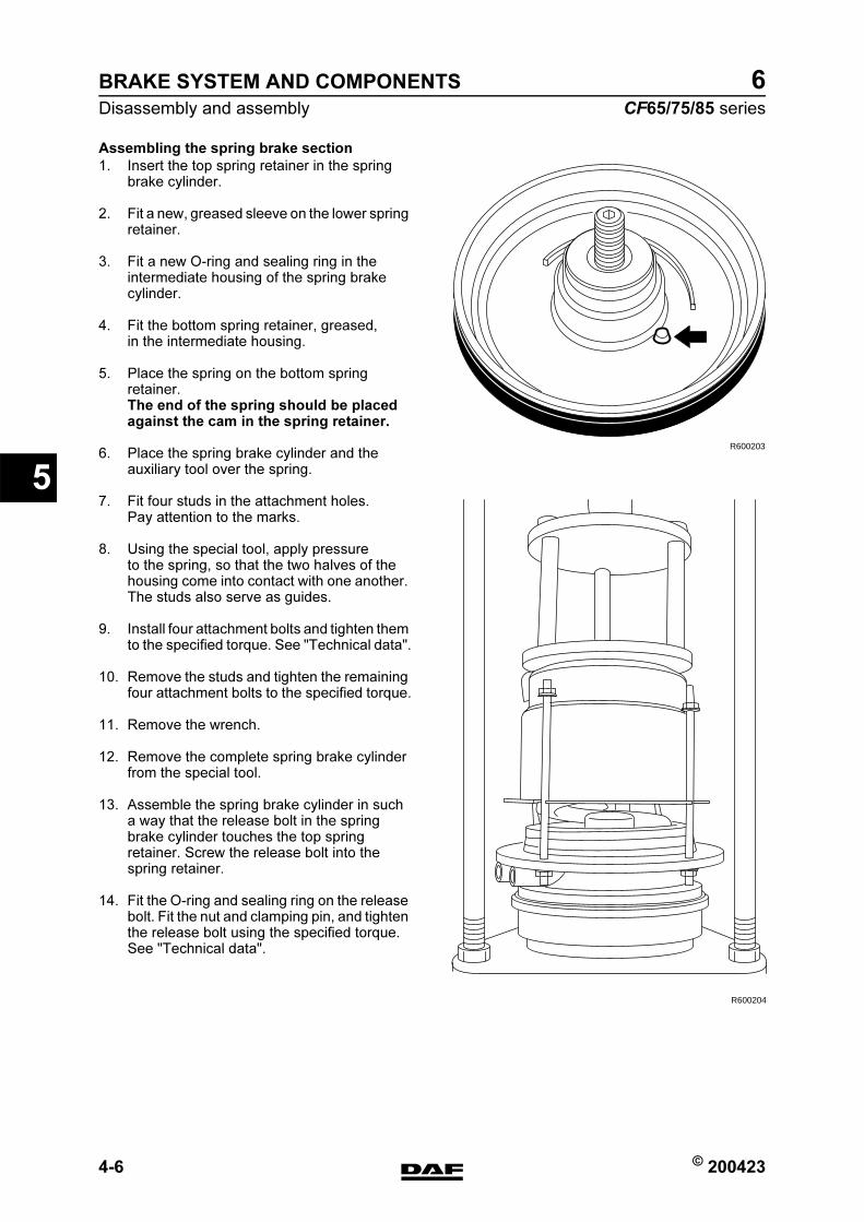
BRAKE SYSTEM AND COMPONENTS
4-6 © 200423
Disassembly and assembly
5
ΧΦ65/75/85 series
6
Assembling the spring brake section
1. Insert the top spring retainer in the spring brake cylinder.
2. Fit a new, greased sleeve on the lower spring retainer.
3. Fit a new O-ring and sealing ring in the intermediate housing of the spring brake cylinder.
4. Fit the bottom spring retainer, greased, in the intermediate housing.
5. Place the spring on the bottom spring retainer.The end of the spring should be placed against the cam in the spring retainer.
6. Place the spring brake cylinder and the auxiliary tool over the spring.
7. Fit four studs in the attachment holes. Pay attention to the marks.
8. Using the special tool, apply pressure to the spring, so that the two halves of the housing come into contact with one another. The studs also serve as guides.
9. Install four attachment bolts and tighten them to the specified torque. See "Technical data".
10. Remove the studs and tighten the remaining four attachment bolts to the specified torque.
11. Remove the wrench.
12. Remove the complete spring brake cylinder from the special tool.
13. Assemble the spring brake cylinder in such a way that the release bolt in the spring brake cylinder touches the top spring retainer. Screw the release bolt into the spring retainer.
14. Fit the O-ring and sealing ring on the release bolt. Fit the nut and clamping pin, and tighten the release bolt using the specified torque. See "Technical data".
R600203
R600204
https://www.truck-manuals.net/
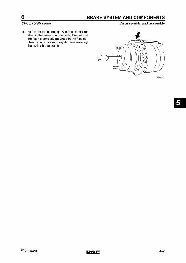
© 200423 4-7
Disassembly and assembly
BRAKE SYSTEM AND COMPONENTS
ΧΦ65/75/85 series
6
5
15. Fit the flexible bleed pipe with the sinter filter fitted at the brake chamber side. Ensure that the filter is correctly mounted in the flexible bleed pipe, to prevent any dirt from entering the spring brake section.
R600197
https://www.truck-manuals.net/
BRAKE SYSTEM AND COMPONENTS
4-8 © 200423
Disassembly and assembly
5
ΧΦ65/75/85 series
6
https://www.truck-manuals.net/

© 200423 1
Contents
BRAKING PERFORMANCE AND BRAKE EQUALISATION
ΧΦ65/75/85 series
6
6
6 Braking performance and brake equalisation
CONTENTS
Page Date
1. GENERAL . . . . . . . . . . . . . . . . . . . . . . . . . . . . . . . . . . . . . . . . . . . . . . . . . . . . . . 1-1 . . . . . 200423
1.1 Introduction . . . . . . . . . . . . . . . . . . . . . . . . . . . . . . . . . . . . . . . . . . . . . . . . 1-1 . . . . . 200423
1.2 What is a vehicle combination with a good braking performance? . . . . . . 1-2 . . . . . 200423
1.3 Brake equalisation by means of brake dynamometer . . . . . . . . . . . . . . . . 1-5 . . . . . 200423
1.4 Brake equalisation form for brake dynamometer. . . . . . . . . . . . . . . . . . . . 1-6 . . . . . 200423
1.5 EC band for a laden tractor/semi-trailer combination . . . . . . . . . . . . . . . . 1-9 . . . . . 200423
1.6 EC band for a laden truck/trailer combination . . . . . . . . . . . . . . . . . . . . . . 1-10 . . . . 200423
2. INSPECTION AND ADJUSTMENT. . . . . . . . . . . . . . . . . . . . . . . . . . . . . . . . . . . 2-1 . . . . . 200423
2.1 Checking braking performance on EBS truck . . . . . . . . . . . . . . . . . . . . . . 2-1 . . . . . 200423
2.2 Inspecting and adjusting brake equalisation of non-EBS truck with non-
EBS trailer vehicle . . . . . . . . . . . . . . . . . . . . . . . . . . . . . . . . . . . . . . . . . . . 2-4 . . . . . 200423
2.3 Inspecting and adjusting brake equalisation of non-EBS truck with EBS
trailer vehicle . . . . . . . . . . . . . . . . . . . . . . . . . . . . . . . . . . . . . . . . . . . . . . . 2-6 . . . . . 200423
2.4 Inspecting and adjusting brake equalisation of EBS truck with non-EBS
trailer vehicle . . . . . . . . . . . . . . . . . . . . . . . . . . . . . . . . . . . . . . . . . . . . . . . 2-8 . . . . . 200423
https://www.truck-manuals.net/

BRAKING PERFORMANCE AND BRAKE EQUALISATION
2 © 200423
Contents
6
ΧΦ65/75/85 series
6
https://www.truck-manuals.net/
© 200423 1-1
General
BRAKING PERFORMANCE AND BRAKE EQUALISATION
ΧΦ65/75/85 series
6
6
1. GENERAL
1.1 INTRODUCTION
How is a good braking performance of a vehicle combination (truck and trailer vehicle) achieved, both for new vehicle combinations and following brake reconditioning, while still guaranteeing interchangeability?The vehicles should meet the legal requirements and all settings should be in accordance with the directives. However, adhering to the directives does not necessarily mean that there will be no brake problems.
Note:Trucks and trailer vehicles may be fitted with an EBS brake system or a non-EBS brake system (conventional brake system).
The adjustability of an EBS brake system is limited, since brake equalisation is managed as a control function by the EBS control system.
https://www.truck-manuals.net/

BRAKING PERFORMANCE AND BRAKE EQUALISATION
1-2 © 200423
General
6
ΧΦ65/75/85 series
6
1.2 WHAT IS A VEHICLE COMBINATION WITH A GOOD BRAKING
PERFORMANCE?
A vehicle combination of which, in laden condition and with a 1 to 3 bar pressure at the service coupling head, the braking deceleration of the tractive unit is the same or virtually the same as that of the drawn vehicle.
Fn
Gd
FFn
Gd
F
Zm.a
Fn
Gd
FFn
Gd
FFn
Gd
F
Z
GG
m.a
R600023
G weight
m = mass
α = deceleration (m x a is the force chang ing the axle load)
Dynamic axle load: during braking, changes the load on each axle.
F = braking force (Fmax = Gd x m)
Gd = dynamic axle load
m = the friction coefficient between tyre and road
Fn = braking force of the wheel brake
https://www.truck-manuals.net/
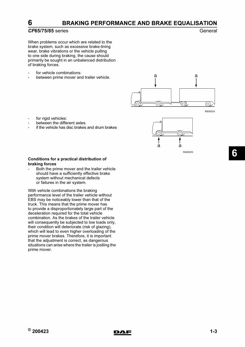
© 200423 1-3
General
BRAKING PERFORMANCE AND BRAKE EQUALISATION
ΧΦ65/75/85 series
6
6
When problems occur which are related to the brake system, such as excessive brake-lining wear, brake vibrations or the vehicle pulling to one side during braking, the cause should primarily be sought in an unbalanced distribution of braking forces.
- for vehicle combinations:- between prime mover and trailer vehicle.
- for rigid vehicles:- between the different axles.- if the vehicle has disc brakes and drum brakes
Conditions for a practical distribution of
braking forces
- Both the prime mover and the trailer vehicle should have a sufficiently effective brake system without mechanical defects or failures in the air system.
With vehicle combinations the braking performance level of the trailer vehicle without EBS may be noticeably lower than that of the truck. This means that the prime mover has to provide a disproportionately large part of the deceleration required for the total vehicle combination. As the brakes of the trailer vehicle will consequently be subjected to low loads only, their condition will deteriorate (risk of glazing), which will lead to even higher overloading of the prime mover brakes. Therefore, it is important that the adjustment is correct, as dangerous situations can arise where the trailer is jostling the prime mover.
a
R600024
a
a aR600025
https://www.truck-manuals.net/
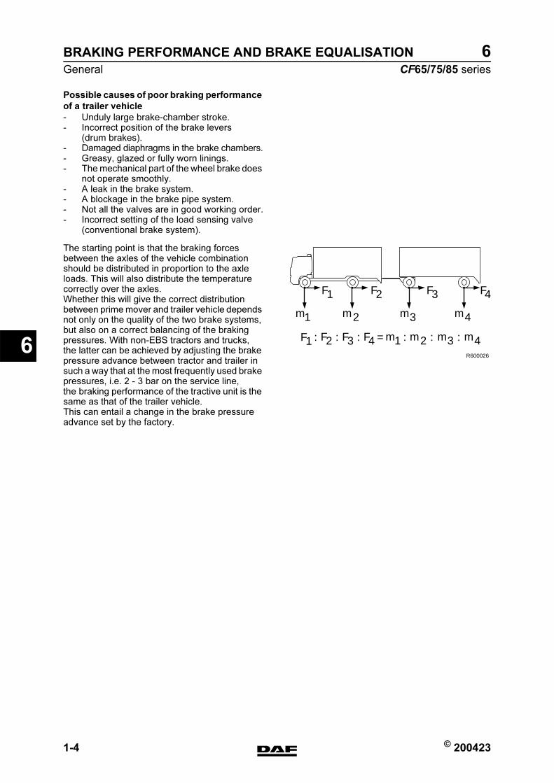
BRAKING PERFORMANCE AND BRAKE EQUALISATION
1-4 © 200423
General
6
ΧΦ65/75/85 series
6
Possible causes of poor braking performance
of a trailer vehicle
- Unduly large brake-chamber stroke.- Incorrect position of the brake levers
(drum brakes).- Damaged diaphragms in the brake chambers.- Greasy, glazed or fully worn linings.- The mechanical part of the wheel brake does
not operate smoothly.- A leak in the brake system.- A blockage in the brake pipe system.- Not all the valves are in good working order.- Incorrect setting of the load sensing valve
(conventional brake system).
The starting point is that the braking forces between the axles of the vehicle combination should be distributed in proportion to the axle loads. This will also distribute the temperature correctly over the axles.Whether this will give the correct distribution between prime mover and trailer vehicle depends not only on the quality of the two brake systems, but also on a correct balancing of the braking pressures. With non-EBS tractors and trucks, the latter can be achieved by adjusting the brake pressure advance between tractor and trailer in such a way that at the most frequently used brake pressures, i.e. 2 - 3 bar on the service line, the braking performance of the tractive unit is the same as that of the trailer vehicle.This can entail a change in the brake pressure advance set by the factory.
R600026
m1 m3 m4
F1
F :1
F2 F3 F4
F2 F3 4
m2
m1 m3 m4m2: F: = : : :
https://www.truck-manuals.net/
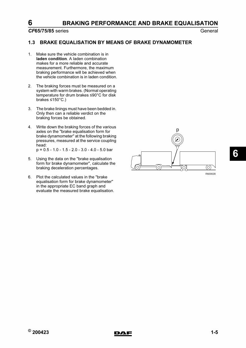
© 200423 1-5
General
BRAKING PERFORMANCE AND BRAKE EQUALISATION
ΧΦ65/75/85 series
6
6
1.3 BRAKE EQUALISATION BY MEANS OF BRAKE DYNAMOMETER
1. Make sure the vehicle combination is in laden condition. A laden combination makes for a more reliable and accurate measurement. Furthermore, the maximum braking performance will be achieved when the vehicle combination is in laden condition.
2. The braking forces must be measured on a system with warm brakes. (Normal operating temperature for drum brakes 90C for disk brakes 150C.)
3. The brake linings must have been bedded in. Only then can a reliable verdict on the braking forces be obtained.
4. Write down the braking forces of the various axles on the "brake equalisation form for brake dynamometer" at the following braking pressures, measured at the service coupling head:p = 0.5 - 1.0 - 1.5 - 2.0 - 3.0 - 4.0 - 5.0 bar
5. Using the data on the "brake equalisation form for brake dynamometer", calculate the braking deceleration percentages.
6. Plot the calculated values in the "brake equalisation form for brake dynamometer" in the appropriate EC band graph and evaluate the measured brake equalisation.
p
R600028
https://www.truck-manuals.net/

BRAKING PERFORMANCE AND BRAKE EQUALISATION
1-6 © 200423
General
6
ΧΦ65/75/85 series
6
1.4 BRAKE EQUALISATION FORM FOR BRAKE DYNAMOMETER
R600119
R LL R L R
0.5
1.0
1.5
2.0
3.0
4.0
5.0
%
%
%
%
%
%
%
R LL R L R
0.5
1.0
1.5
2.0
3.0
4.0
5.0
%
%
%
%
%
%
%
p
p
p
p
m1+ m2+.. . . . . m1+ m2+.. . . . .
m1+m2+.. . . . .m1+ m2+.. . . . .
R
L
R
L
R
L
R
L
R
L
R
L
F1 F2 F3
F1 F2 F3
F1+F2+F3 m1+ m2+.. . . . .
F1+F2+F3X 100 %
F1+F2+F3
X 100 %
m1+m2+.. . . . .
F1+F2+F3
https://www.truck-manuals.net/
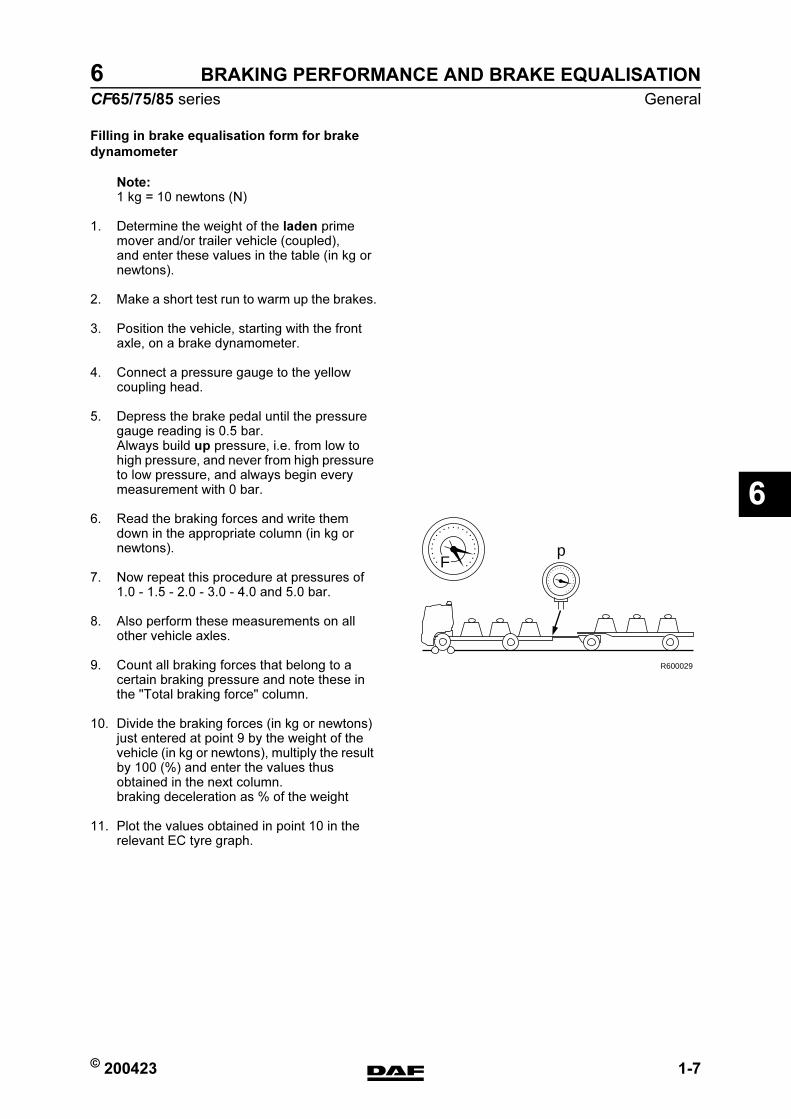
© 200423 1-7
General
BRAKING PERFORMANCE AND BRAKE EQUALISATION
ΧΦ65/75/85 series
6
6
Filling in brake equalisation form for brake
dynamometer
Note:1 kg = 10 newtons (N)
1. Determine the weight of the laden prime mover and/or trailer vehicle (coupled), and enter these values in the table (in kg or newtons).
2. Make a short test run to warm up the brakes.
3. Position the vehicle, starting with the front axle, on a brake dynamometer.
4. Connect a pressure gauge to the yellow coupling head.
5. Depress the brake pedal until the pressure gauge reading is 0.5 bar.Always build up pressure, i.e. from low to high pressure, and never from high pressure to low pressure, and always begin every measurement with 0 bar.
6. Read the braking forces and write them down in the appropriate column (in kg or newtons).
7. Now repeat this procedure at pressures of 1.0 - 1.5 - 2.0 - 3.0 - 4.0 and 5.0 bar.
8. Also perform these measurements on all other vehicle axles.
9. Count all braking forces that belong to a certain braking pressure and note these in the "Total braking force" column.
10. Divide the braking forces (in kg or newtons) just entered at point 9 by the weight of the vehicle (in kg or newtons), multiply the result by 100 (%) and enter the values thus obtained in the next column.braking deceleration as % of the weight
11. Plot the values obtained in point 10 in the relevant EC tyre graph.
Fp
R600029
https://www.truck-manuals.net/
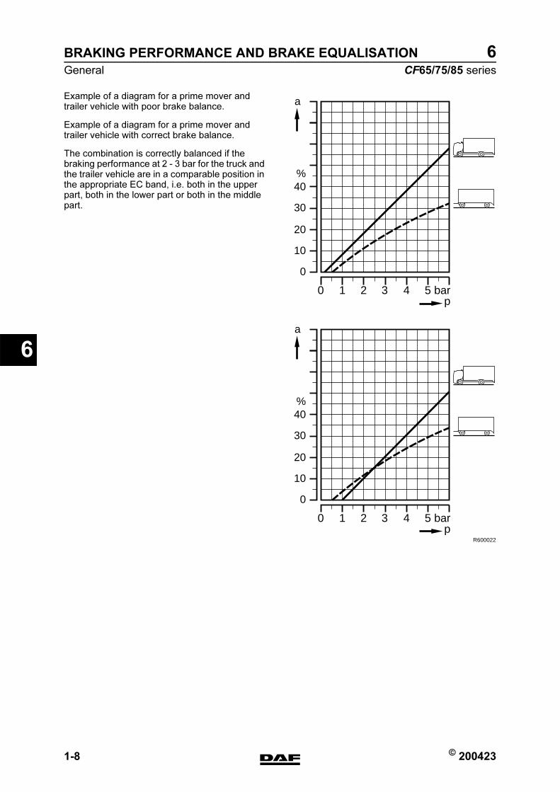
BRAKING PERFORMANCE AND BRAKE EQUALISATION
1-8 © 200423
General
6
ΧΦ65/75/85 series
6
Example of a diagram for a prime mover and trailer vehicle with poor brake balance.
Example of a diagram for a prime mover and trailer vehicle with correct brake balance.
The combination is correctly balanced if the braking performance at 2 - 3 bar for the truck and the trailer vehicle are in a comparable position in the appropriate EC band, i.e. both in the upper part, both in the lower part or both in the middle part.
%
a
40
30
20
10
0
10 2 3 4 5 barp
%
a
40
30
20
10
0
10 2 3 4 5 barp
R600022
https://www.truck-manuals.net/
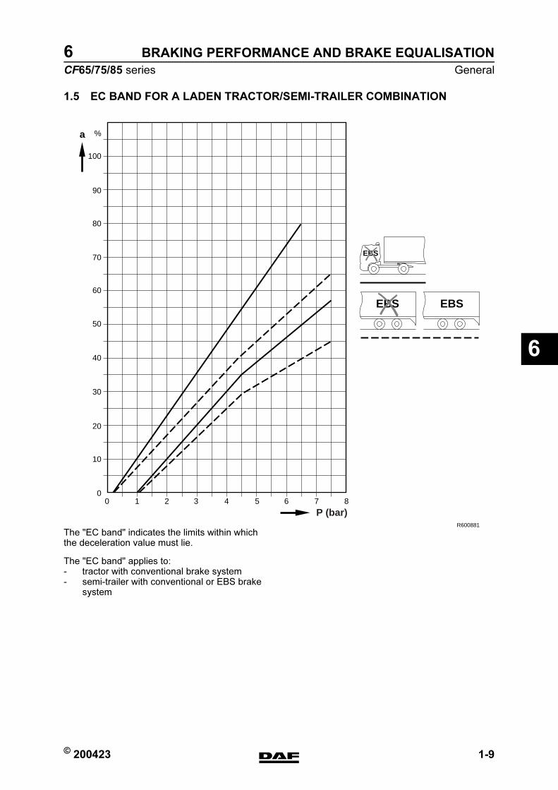
© 200423 1-9
General
BRAKING PERFORMANCE AND BRAKE EQUALISATION
ΧΦ65/75/85 series
6
6
1.5 EC BAND FOR A LADEN TRACTOR/SEMI-TRAILER COMBINATION
The "EC band" indicates the limits within which the deceleration value must lie.
The "EC band" applies to:- tractor with conventional brake system- semi-trailer with conventional or EBS brake
system
100
%a
90
80
70
60
50
40
30
20
10
010 2 3 4 5 6 7 8
R600881
EBS EBS
P (bar)
EBS
https://www.truck-manuals.net/

BRAKING PERFORMANCE AND BRAKE EQUALISATION
1-10 © 200423
General
6
ΧΦ65/75/85 series
6
1.6 EC BAND FOR A LADEN TRUCK/TRAILER COMBINATION
The "EC band" indicates the limits within which the deceleration value must lie.
The "EC band" applies to:- truck with conventional brake system.- trailer with conventional or EBS brake
system.
Note:The following applies to mid-axle trailers fitted with air brakes:The permissible ratio between the deceleration and the pressure at the yellow coupling head of a laden mid-axle trailer with air brakes should be within the two areas derived from the EC band for a laden truck/trailer combination, for which the vertical scale has been multiplied by 0.95.
100
%
90
80
70
60
50
40
30
20
10
010 2 3 4 5 6 7 8
R600880
P (bar)
EBS EBS
a
EBS
https://www.truck-manuals.net/

© 200423 2-1
Inspection and adjustment
BRAKING PERFORMANCE AND BRAKE EQUALISATION
ΧΦ65/75/85 series
6
6
2. INSPECTION AND ADJUSTMENT
2.1 CHECKING BRAKING PERFORMANCE ON EBS TRUCK
It is not easy to perform a realistic braking deceleration test or braking deceleration calculation on a vehicle that is not fully laden and is fitted with an EBS system on a test bench.
The reason for this is that the EBS system has its own control principle which calculates the optimum brake pressure to the front and rear axles in relation to the dynamic axle loads.
Note:The test bench function and deceleration measurement can be carried out on a vehicle with the EBS system in fully laden state, if desired.
It is however possible to inspect the brake performance of the vehicle by means of braking force measurements, though only the static condition of the brake system can be assessed.
Inspection, brake performance
1. The brake performance of the vehicle can be inspected by placing the fully laden vehicle on a test bench and then activating the test bench function of the EBS system.
2. The braking forces must be measured on a brake system with warm brakes (temperature under normal operating conditions).
3. The braking forces cannot be evaluated until the brake lining has bedded in.
4. The braking forces must be measured in relation to the pressure in the brake cylinder.
5. Based on the relevant graph (see "Technical data"), determine whether the braking performance is correct. An example is used to explain how the measured braking performance should be evaluated.
https://www.truck-manuals.net/
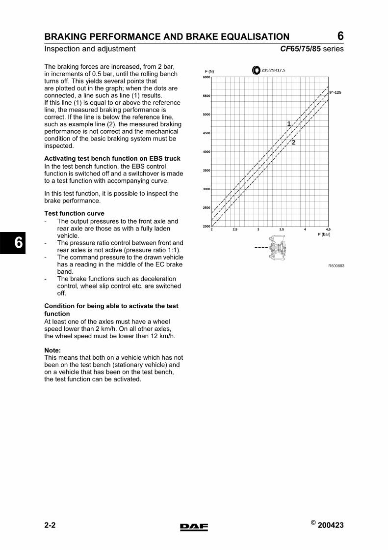
BRAKING PERFORMANCE AND BRAKE EQUALISATION
2-2 © 200423
Inspection and adjustment
6
ΧΦ65/75/85 series
6
The braking forces are increased, from 2 bar, in increments of 0.5 bar, until the rolling bench turns off. This yields several points that are plotted out in the graph; when the dots are connected, a line such as line (1) results. If this line (1) is equal to or above the reference line, the measured braking performance is correct. If the line is below the reference line, such as example line (2), the measured braking performance is not correct and the mechanical condition of the basic braking system must be inspected.
Activating test bench function on EBS truck
In the test bench function, the EBS control function is switched off and a switchover is made to a test function with accompanying curve.
In this test function, it is possible to inspect the brake performance.
Test function curve
- The output pressures to the front axle and rear axle are those as with a fully laden vehicle.
- The pressure ratio control between front and rear axles is not active (pressure ratio 1:1).
- The command pressure to the drawn vehicle has a reading in the middle of the EC brake band.
- The brake functions such as deceleration control, wheel slip control etc. are switched off.
Condition for being able to activate the test
function
At least one of the axles must have a wheel speed lower than 2 km/h. On all other axles, the wheel speed must be lower than 12 km/h.
Note:This means that both on a vehicle which has not been on the test bench (stationary vehicle) and on a vehicle that has been on the test bench, the test function can be activated.
2 2,5 3 3,5 4 4,5
6000
5500
5000
4500
4000
3500
3000
2500
2000
9"-125
R600883
235/75R17,5
P (bar)
F (N)
1
2
https://www.truck-manuals.net/
© 200423 2-3
Inspection and adjustment
BRAKING PERFORMANCE AND BRAKE EQUALISATION
ΧΦ65/75/85 series
6
6
Activation of the test function
1. Switch the vehicle ignition off.
2. Apply the brake pedal. The test function will now be activated if the condition has been met.
Note:- If during application of the brake pedal
the contact is turned on, the test function will remain active even if the brake pedal is then released.
- The test function will be automatically switched off if the condition is no longer met or if, when the contact is on, the contact is switched off when the brake pedal is not being applied.
https://www.truck-manuals.net/
BRAKING PERFORMANCE AND BRAKE EQUALISATION
2-4 © 200423
Inspection and adjustment
6
ΧΦ65/75/85 series
6
2.2 INSPECTING AND ADJUSTING BRAKE EQUALISATION OF NON-EBS
TRUCK WITH NON-EBS TRAILER VEHICLE
Inspecting brake equalisation of non-EBS
truck with non-EBS trailer vehicle
1. Take a test drive and evaluate the braking behaviour.
2. In the case of disc brakes, inspect the mechanical condition of the brake calliper, brake disc and brake pads. In the case of drum brakes, inspect the mechanical condition of the brake drums and brake linings. Their condition may provide clues to the settings that need to be made.
3. Perform a brake equalisation test using a brake dynamometer and fill in the "Brake equalisation form for brake dynamometer". See "General".
4. Evaluate the brake equalisation of the combination using the "EC band graph". The combination is correctly balanced if the braking performance at 2 - 3 bar for the truck and the trailer vehicle are in a comparable position in the appropriate EC band, i.e. both in the upper part, both in the lower part or both in the middle part.
Note:On a tractor/drawn vehicle combination the values for the drawn vehicle may be slightly lower than those for the prime mover. The deceleration values for the truck and the drawn vehicle of a truck/trailer combination should be the same. The reason for this lies in the dynamic axle load displacement, which on semi-trailers causes a transfer of weight to the tractive unit, whereas on trailers it does not cause a transfer of weight to the tractive unit.
5. Due to the adjustment of the brake pressure advance on the truck and/or trailer vehicle the deceleration lines in the "EC band graph" can be affected.
Note:For optimum interchangeability of vehicles, the correct choice between these two alternatives must be made.
6. If the mechanical condition of the wheel brakes, the results of the test drive and the data obtained from the brake equalisation test using the brake dynamometer give cause for doing so, the brake pressure advance of the trailer vehicle control valve can be adjusted.
https://www.truck-manuals.net/

© 200423 2-5
Inspection and adjustment
BRAKING PERFORMANCE AND BRAKE EQUALISATION
ΧΦ65/75/85 series
6
6
Adjusting brake equalisation of non-EBS
truck with non-EBS trailer vehicle
1. When the brake pressure advance in the trailer vehicle control valve on the truck is increased or decreased, the position of the curve for the trailer vehicle (B) in the graph will not be affected. This is because the reference pressures are measured at the yellow coupling head (= service line). For the same reason, however, the curve for the truck (A) will shift to the right or the left (will appear to be lower or higher respectively).So the horizontal axis indicates how much the brake pressure advance has to be changed. Reducing the brake pressure advance results in increased deceleration of the truck. Increasing the brake pressure advance results in decreased deceleration of the truck.
Note:Increasing the brake pressure advance on the trailer vehicle reaction valve on the trailer vehicle results in increased deceleration of the trailer vehicle.
Bear in mind that an increase in the brake pressure advance does not necessarily improve the braking performance of the trailer vehicle. It only means that the brake pressure balance between prime mover and trailer vehicle is changed. Moreover, in the event of an emergency stop the poorer braking performance of the trailer vehicle will again be noticeable, as the brake pressure advance is eliminated when the maximum brake pressure is used.
2. So the horizontal axis indicates how much the brake pressure advance has to be changed.
3. Take a test run, perform a brake equalisation test using a brake dynamometer and fill in the "Brake equalisation form for brake dynamometer". See "General". If desired or required, the setting of the trailer vehicle control valve can be adjusted again.
4. If the desired brake equalisation cannot be achieved, the cause must be sought and remedied by means of the diagnostics table. See "Diagnostics".
R600774
0
10
20
30
40
50
60
70
80
a(%) A
B
1 2 3 4 5 6 7 8p(bar)
}
https://www.truck-manuals.net/
BRAKING PERFORMANCE AND BRAKE EQUALISATION
2-6 © 200423
Inspection and adjustment
6
ΧΦ65/75/85 series
6
2.3 INSPECTING AND ADJUSTING BRAKE EQUALISATION OF NON-EBS
TRUCK WITH EBS TRAILER VEHICLE
Inspecting brake equalisation of non-EBS
truck with EBS trailer vehicle
1. Take a test drive and evaluate the braking behaviour.
2. In the case of disc brakes, inspect the mechanical condition of the brake calliper, brake disc and brake pads. In the case of drum brakes, inspect the mechanical condition of the brake drums and brake linings. Their condition may provide clues to the settings that need to be made.
3. Perform a brake equalisation test using a brake dynamometer and fill in the "Brake equalisation form for brake dynamometer". See "General".
Note:The EBS trailer vehicle must be correctly connected and the test function of the EBS system must be activated.
4. Evaluate the brake equalisation of the combination using the "EC band graph". The combination is correctly balanced if the braking performance at 2 - 3 bar for the truck and the trailer vehicle are in a comparable position in the appropriate EC band, i.e. both in the upper part, both in the lower part or both in the middle part.
Note:On a tractor/semi-trailer combination the values for the drawn vehicle may be slightly lower than those for the tractor. The deceleration values for the truck and the drawn vehicle of a truck/trailer combination should be the same. The reason for this lies in the dynamic axle load displacement, which on semi-trailers causes a transfer of weight to the tractive unit, whereas on trailers it does not cause a transfer of weight to the tractive unit.
5. Due to the adjustment of the brake pressure advance on the truck, the deceleration line in the "EC band graph" can be affected.
6. If the mechanical condition of the wheel brakes, the results of the test drive and the data obtained from the brake equalisation test using the brake dynamometer give cause for doing so, the brake pressure advance of the trailer vehicle control valve can be adjusted.
https://www.truck-manuals.net/
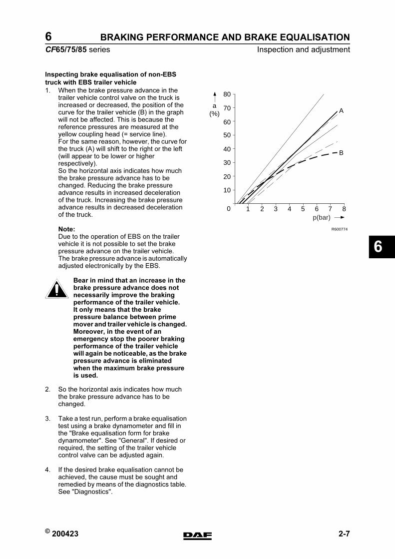
© 200423 2-7
Inspection and adjustment
BRAKING PERFORMANCE AND BRAKE EQUALISATION
ΧΦ65/75/85 series
6
6
Inspecting brake equalisation of non-EBS
truck with EBS trailer vehicle
1. When the brake pressure advance in the trailer vehicle control valve on the truck is increased or decreased, the position of the curve for the trailer vehicle (B) in the graph will not be affected. This is because the reference pressures are measured at the yellow coupling head (= service line). For the same reason, however, the curve for the truck (A) will shift to the right or the left (will appear to be lower or higher respectively).So the horizontal axis indicates how much the brake pressure advance has to be changed. Reducing the brake pressure advance results in increased deceleration of the truck. Increasing the brake pressure advance results in decreased deceleration of the truck.
Note:Due to the operation of EBS on the trailer vehicle it is not possible to set the brake pressure advance on the trailer vehicle. The brake pressure advance is automatically adjusted electronically by the EBS.
Bear in mind that an increase in the brake pressure advance does not necessarily improve the braking performance of the trailer vehicle. It only means that the brake pressure balance between prime mover and trailer vehicle is changed. Moreover, in the event of an emergency stop the poorer braking performance of the trailer vehicle will again be noticeable, as the brake pressure advance is eliminated when the maximum brake pressure is used.
2. So the horizontal axis indicates how much the brake pressure advance has to be changed.
3. Take a test run, perform a brake equalisation test using a brake dynamometer and fill in the "Brake equalisation form for brake dynamometer". See "General". If desired or required, the setting of the trailer vehicle control valve can be adjusted again.
4. If the desired brake equalisation cannot be achieved, the cause must be sought and remedied by means of the diagnostics table. See "Diagnostics".
R600774
0
10
20
30
40
50
60
70
80
a(%) A
B
1 2 3 4 5 6 7 8p(bar)
}
https://www.truck-manuals.net/
BRAKING PERFORMANCE AND BRAKE EQUALISATION
2-8 © 200423
Inspection and adjustment
6
ΧΦ65/75/85 series
6
2.4 INSPECTING AND ADJUSTING BRAKE EQUALISATION OF EBS TRUCK
WITH NON-EBS TRAILER VEHICLE
Inspecting brake equalisation of EBS truck
with non-EBS trailer vehicle
1. Take a test drive and evaluate the braking behaviour.
2. Check the mechanical condition of the braking system of the EBS truck with the help of the brake performance measurement, using a rolling testing device.
3. Connect a pressure gauge to the yellow coupling head of the trailer. Activate the testing function of the EBS truck and gradually depress the brake pedal. Now you must gradually increase the pressure on the yellow coupling head and eventually exert a pressure value in excess of 8 bar.
4. Evaluate the brake performance of the non-EBS trailer with the "EC band graph". The measured deceleration must be within the EC band graph.
5. By adjusting the advance pressure in the trailer reaction valve of the non-EBS trailer, the deceleration line in the EC band graph can be influenced. Changing the advance pressure is only allowable if the mechanical condition of the brake system of the trailer allows for this.
Inspecting brake equalisation of EBS truck
with non-EBS trailer vehicle
1. If the advance pressure of the trailer reaction valve is increased or decreased, this will also result in an increase or decrease of the measured deceleration of the trailer vehicle.
https://www.truck-manuals.net/
© 200423 2-9
Inspection and adjustment
BRAKING PERFORMANCE AND BRAKE EQUALISATION
ΧΦ65/75/85 series
6
6
Bear in mind that an increase in the brake pressure advance does not necessarily improve the braking performance of the trailer vehicle. It only means that the brake pressure balance between prime mover and trailer vehicle is changed. Moreover, in the event of an emergency stop the poorer braking performance of the trailer vehicle will again be noticeable, as the brake pressure advance is eliminated when the maximum brake pressure is used.
Note:The EBS system on the truck has a system that automatically adjusts the brake pressures. It is not possible to adjust it. If the EBS system has not stored an error code and the brakes of the truck are in proper condition, the cause of the brake troubles must be sought in the condition and sizing of the brakes of the trailer vehicle. If an improvement of comfort (pulling or pushing) is desired for low brake decelerations, this is possible by changing the pressure pulse control of the trailer vehicle.
}
https://www.truck-manuals.net/
BRAKING PERFORMANCE AND BRAKE EQUALISATION
2-10 © 200423
Inspection and adjustment
6
ΧΦ65/75/85 series
6
https://www.truck-manuals.net/