6.3. micro and mesoporous materials 6.3.1. ordered...
TRANSCRIPT
6.3. Micro and Mesoporous Materials According to the classification made by IUPAC1, porous solids can be grouped into three categories, depending on their pore diameter: microporous (d < 2 nm), mesoporous (2 nm < d < 50 nm), and macroporous (d > 50 nm) materials. Almost all of zeolites and their derivatives are microporous, whereas surfactant templated mesoporous materials and most xerogels and aerogels are mesoporous materials. In this section, we will briefly introduce these meso and microporous materials and their respective synthesis techniques. This field has been extensively covered with excellent reviewed articles2,3. 6.3.1. Ordered Mesoporous Structures Ordered mesoporous materials are made with a combination of using self-assembled surfactants as template and simultaneous sol-gel condensation around template. Mesoporous materials may have many important technological applications as supports, adsorbents, sieves, or nanoscale chemical reactors. Such materials have uniformly sized and shaped pores with diameters ranging from 3 nm to several tens nanometers and microns long, and often have a very large pore volume (up to 70%) and very high surface area (> 700 m2/g). Before we discuss the details of the synthesis of ordered mesoporous materials, a brief introduction to surfactants and the formation of micelles. Surfactants are organic molecules, which comprise two parts with different polarity4. One part is a hydrocarbon chain (often referred to as polymer tail), which is nonpolar and hence hydrophobic and lipophilic, whereas the other is polar and hydrophilic (often called hydrophilic head). Because of such a molecular structure, surfactants tend to enrich at the surface of a solution or interface between aqueous and hydrocarbon solvents, so that the hydrophilic head can turn towards the aqueous solution, resulting in a reduction of surface or interface energy. Such concentration segregation is spontaneous and thermodynamically favorable. Surfactant molecules can be generally classified into four families, and they are known as anionic, cationic, nonionic, and amphoteric surfactants, which are briefly discussed below:
1. Typical anionic surfactants are sulfonated compound with a general formula R-SO3Na, and sulfated compounds of R-OSO3Na, with R being an alkyl chain consisting of 11 to 21 carbon atoms.
2. Cationic surfactants commonly comprise of an alkyl hydrophobic tail and a methyl-ammonium ionic compound head, such as cetyl trimethyl ammonium bromide (CTAB), C16H33N(CH3)3Br and cetyl trimethyl ammonium chloride (CTAC), C16H33N(CH3)3Cl.
3. Nonionic surfactants do not dissociate into ions when dissolved in a solvent as both anionic and cationic surfactant. Their hydrophilic head is a polar group such as ether, R-O-R, alcohol, R-OH, carbonyl, R-CO-R, and amine, R-NH-R.
4. Amphoteric surfactants have properties similar to either nonionic surfactants or ionic surfactants. Examples are betaines and phospholipides.
1
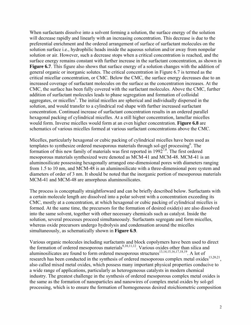
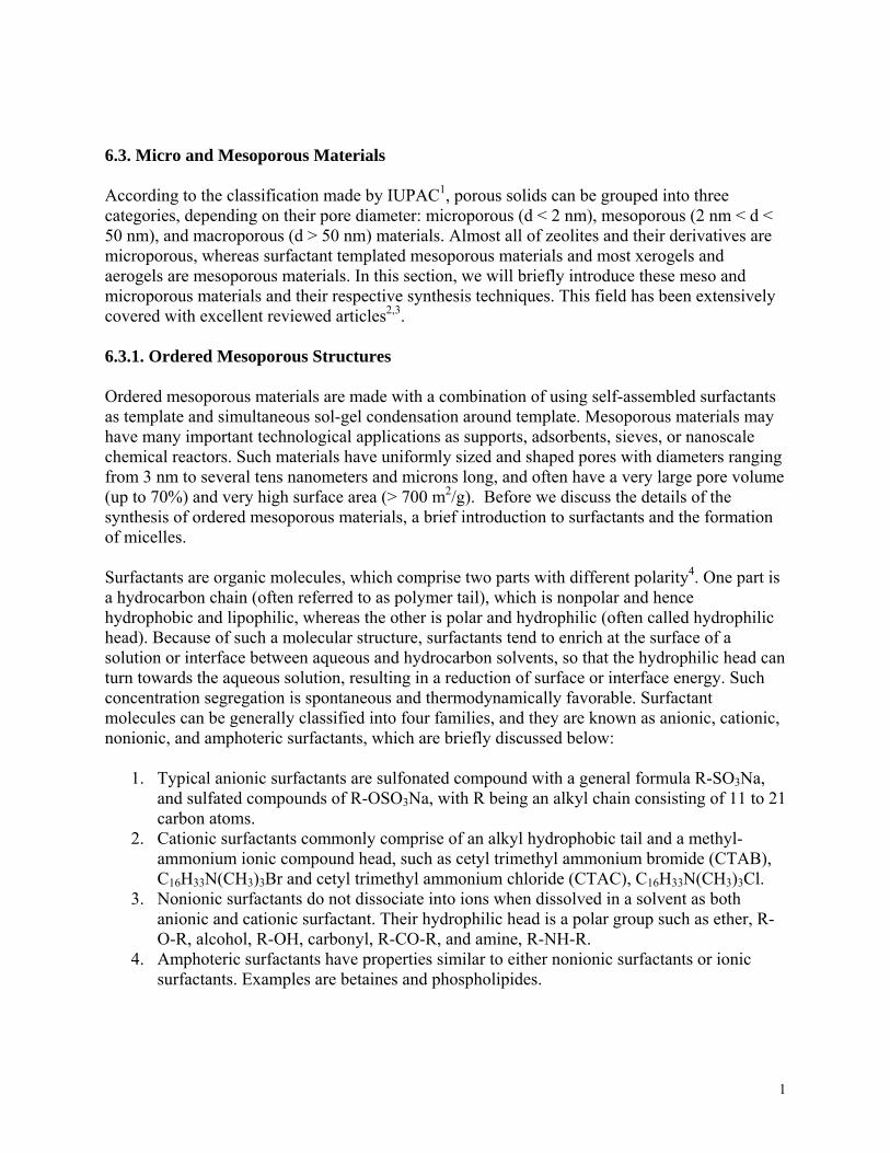
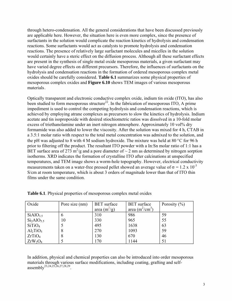
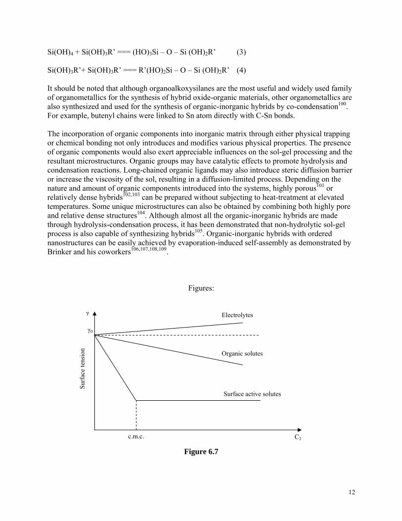
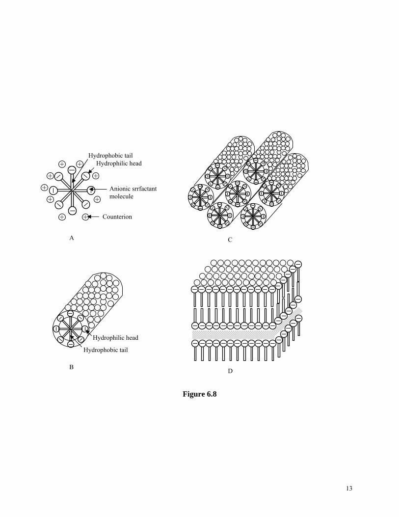
When surfactants dissolve into a solvent forming a solution, the surface energy of the solution will decrease rapidly and linearly with an increasing concentration. This decrease is due to the preferential enrichment and the ordered arrangement of surface of surfactant molecules on the solution surface i.e., hydrophilic heads inside the aqueous solution and/or away from nonpolar solution or air. However, such a decrease stops when a critical concentration is reached, and the surface energy remains constant with further increase in the surfactant concentration, as shown in Figure 6.7. This figure also shows that surface energy of a solution changes with the addition of general organic or inorganic solutes. The critical concentration in Figure 6.7 is termed as the critical micellar concentration, or CMC. Below the CMC, the surface energy decreases due to an increased coverage of surfactant molecules on the surface as the concentration increases. At the CMC, the surface has been fully covered with the surfactant molecules. Above the CMC, further addition of surfactant molecules leads to phase segregation and formation of colloidal aggregates, or micelles5. The initial micelles are spherical and individually dispersed in the solution, and would transfer to a cylindrical rod shape with further increased surfactant concentration. Continued increase of surfactant concentration results in an ordered parallel hexagonal packing of cylindrical micelles. At a still higher concentration, lamellar micelles would form. Inverse micelles would form at an even higher concentration. Figure 6.8 are schematics of various micelles formed at various surfactant concentrations above the CMC. Micelles, particularly hexagonal or cubic packing of cylindrical micelles have been used as templates to synthesize ordered mesoporous materials through sol-gel processing6. The formation of this new family of materials was first reported in 19927,8. The first ordered mesoporous materials synthesized were denoted as MCM-41 and MCM-48. MCM-41 is an aluminosilicate possessing hexagonally arranged one-dimensional pores with diameters ranging from 1.5 to 10 nm, and MCM-48 is an aluminosilicate with a three-dimensional pore system and diameters of order of 3 nm. It should be noted that the inorganic portion of mesoporous materials MCM-41 and MCM-48 are amorphous aluminosilicates. The process is conceptually straightforward and can be briefly described below. Surfactants with a certain molecule length are dissolved into a polar solvent with a concentration exceeding its CMC, mostly at a concentration, at which hexagonal or cubic packing of cylindrical micelles is formed. At the same time, the precursors for the formation of desired oxide(s) are also dissolved into the same solvent, together with other necessary chemicals such as catalyst. Inside the solution, several processes proceed simultaneously. Surfactants segregate and form micelles, whereas oxide precursors undergo hydrolysis and condensation around the micelles simultaneously, as schematically shown in Figure 6.9. Various organic molecules including surfactants and block copolymers have been used to direct the formation of ordered mesoporous materials9, , ,10 11 12. Various oxides other than silica and aluminosilicates are found to form ordered mesoporous structures13, , , , , ,14 15 16 17 18 19. A lot of research has been conducted in the synthesis of ordered mesoporous complex metal oxides13, ,20 21, also called mixed metal oxides, which possess many important physical properties conducive to a wide range of applications, particularly as heterogeneous catalysts in modern chemical industry. The greatest challenge in the synthesis of ordered mesoporous complex metal oxides is the same as the formation of nanoparticles and nanowires of complex metal oxides by sol-gel processing, which is to ensure the formation of homogeneous desired stoichiometric composition
2
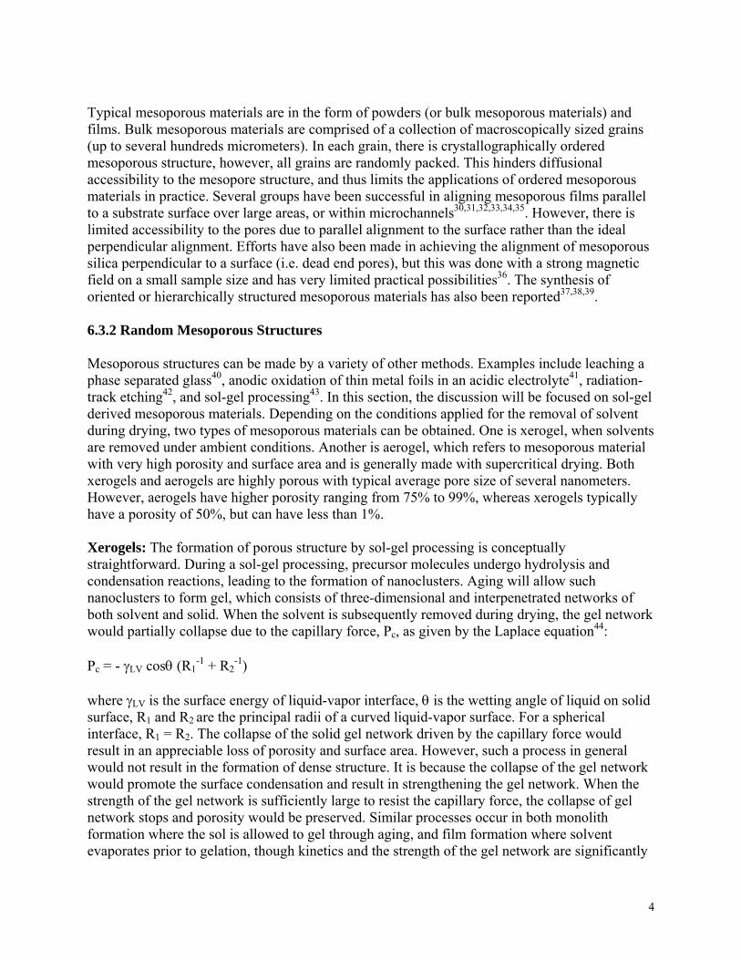
through hetero-condensation. All the general considerations that have been discussed previously are applicable here. However, the situation here is even more complex, since the presence of surfactants in the solution would complicate the reaction kinetics of hydrolysis and condensation reactions. Some surfactants would act as catalysts to promote hydrolysis and condensation reactions. The presence of relatively large surfactant molecules and micelles in the solution would certainly have a steric effect on the diffusion process. Although all these surfactant effects are present in the synthesis of single metal oxide mesoporous materials, a given surfactant may have varied degree effects on different precursors. Therefore, the influences of surfactants on the hydrolysis and condensation reactions in the formation of ordered mesoporous complex metal oxides should be carefully considered. Table 6.1 summarizes some physical properties of mesoporous complex oxides and Figure 6.10 shows TEM images of various mesoporous materials. Optically transparent and electronic conductive complex oxide, indium tin oxide (ITO), has also been studied to form mesoporous structure22. In the fabrication of mesoporous ITO, A prime impediment is used to control the competing hydrolysis and condensation reactions, which is achieved by employing atrane complexes as precursors to slow the kinetics of hydrolysis. Indium acetate and tin isopropoxide with desired stiochiometric ratios was dissolved in a 10-fold molar excess of triethanolamine under an inert nitrogen atmosphere. Approximately 10 vol% dry formamide was also added to lower the viscosity. After the solution was mixed for 4 h, CTAB in a 3.5:1 molar ratio with respect to the total metal concentration was admixed to the solution, and the pH was adjusted to 8 with 4 M sodium hydroxide. The mixture was held at 80 °C for 96 h prior to filtering off the product. The resultant ITO powder with a In:Sn molar ratio of 1:1 has a BET surface area of 273 m2/g and a pore diameter of ~ 2 nm as determined by nitrogen sorption isotherms. XRD indicates the formation of crystalline ITO after calcinations at unspecified temperatures, and TEM image shows a worm-hole topography. However, electrical conductivity measurements taken on a water-free pressed pellet showed an average value of σ = 1.2 x 10⁻³ S/cm at room temperature, which is about 3 orders of magnitude lower than that of ITO thin films under the same condition. Table 6.1. Physical properties of mesoporous complex metal oxides Oxide Pore size (nm) BET surface
area (m2/g) BET surface area (m2/cm3)
Porosity (%)
SiAlO3.5 Si2AlO5.5SiTiO4Al2TiO5ZrTiO4ZrW2O8
6 10 5 8 8 5
310 330 495 270 130 170
986 965 1638 1093 670 1144
59 55 63 59 46 51
In addition, physical and chemical properties can also be introduced into order mesoporous materials through various surface modifications, including coating, grafting and self-assembly23, , , , , ,24 25 26 27 28 29.
3
Typical mesoporous materials are in the form of powders (or bulk mesoporous materials) and films. Bulk mesoporous materials are comprised of a collection of macroscopically sized grains (up to several hundreds micrometers). In each grain, there is crystallographically ordered mesoporous structure, however, all grains are randomly packed. This hinders diffusional accessibility to the mesopore structure, and thus limits the applications of ordered mesoporous materials in practice. Several groups have been successful in aligning mesoporous films parallel to a substrate surface over large areas, or within microchannels30, , , , ,31 32 33 34 35. However, there is limited accessibility to the pores due to parallel alignment to the surface rather than the ideal perpendicular alignment. Efforts have also been made in achieving the alignment of mesoporous silica perpendicular to a surface (i.e. dead end pores), but this was done with a strong magnetic field on a small sample size and has very limited practical possibilities36. The synthesis of oriented or hierarchically structured mesoporous materials has also been reported37, ,38 39. 6.3.2 Random Mesoporous Structures Mesoporous structures can be made by a variety of other methods. Examples include leaching a phase separated glass40, anodic oxidation of thin metal foils in an acidic electrolyte41, radiation-track etching42, and sol-gel processing43. In this section, the discussion will be focused on sol-gel derived mesoporous materials. Depending on the conditions applied for the removal of solvent during drying, two types of mesoporous materials can be obtained. One is xerogel, when solvents are removed under ambient conditions. Another is aerogel, which refers to mesoporous material with very high porosity and surface area and is generally made with supercritical drying. Both xerogels and aerogels are highly porous with typical average pore size of several nanometers. However, aerogels have higher porosity ranging from 75% to 99%, whereas xerogels typically have a porosity of 50%, but can have less than 1%. Xerogels: The formation of porous structure by sol-gel processing is conceptually straightforward. During a sol-gel processing, precursor molecules undergo hydrolysis and condensation reactions, leading to the formation of nanoclusters. Aging will allow such nanoclusters to form gel, which consists of three-dimensional and interpenetrated networks of both solvent and solid. When the solvent is subsequently removed during drying, the gel network would partially collapse due to the capillary force, Pc, as given by the Laplace equation44: Pc = - γLV cosθ (R1
-1 + R2-1)
where γLV is the surface energy of liquid-vapor interface, θ is the wetting angle of liquid on solid surface, R1 and R2 are the principal radii of a curved liquid-vapor surface. For a spherical interface, R1 = R2. The collapse of the solid gel network driven by the capillary force would result in an appreciable loss of porosity and surface area. However, such a process in general would not result in the formation of dense structure. It is because the collapse of the gel network would promote the surface condensation and result in strengthening the gel network. When the strength of the gel network is sufficiently large to resist the capillary force, the collapse of gel network stops and porosity would be preserved. Similar processes occur in both monolith formation where the sol is allowed to gel through aging, and film formation where solvent evaporates prior to gelation, though kinetics and the strength of the gel network are significantly
4
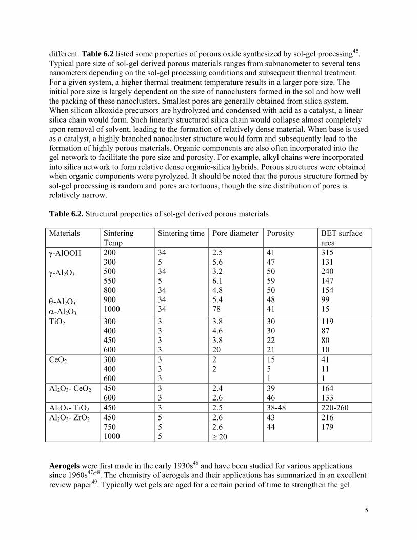
different. Table 6.2 listed some properties of porous oxide synthesized by sol-gel processing45. Typical pore size of sol-gel derived porous materials ranges from subnanometer to several tens nanometers depending on the sol-gel processing conditions and subsequent thermal treatment. For a given system, a higher thermal treatment temperature results in a larger pore size. The initial pore size is largely dependent on the size of nanoclusters formed in the sol and how well the packing of these nanoclusters. Smallest pores are generally obtained from silica system. When silicon alkoxide precursors are hydrolyzed and condensed with acid as a catalyst, a linear silica chain would form. Such linearly structured silica chain would collapse almost completely upon removal of solvent, leading to the formation of relatively dense material. When base is used as a catalyst, a highly branched nanocluster structure would form and subsequently lead to the formation of highly porous materials. Organic components are also often incorporated into the gel network to facilitate the pore size and porosity. For example, alkyl chains were incorporated into silica network to form relative dense organic-silica hybrids. Porous structures were obtained when organic components were pyrolyzed. It should be noted that the porous structure formed by sol-gel processing is random and pores are tortuous, though the size distribution of pores is relatively narrow. Table 6.2. Structural properties of sol-gel derived porous materials Materials Sintering
Temp Sintering time Pore diameter Porosity BET surface
area γ-AlOOH γ-Al2O3 θ-Al2O3
α-Al2O3
200 300 500 550 800 900 1000
34 5 34 5 34 34 34
2.5 5.6 3.2 6.1 4.8 5.4 78
41 47 50 59 50 48 41
315 131 240 147 154 99 15
TiO2 300 400 450 600
3 3 3 3
3.8 4.6 3.8 20
30 30 22 21
119 87 80 10
CeO2 300 400 600
3 3 3
2 2
15 5 1
41 11 1
Al2O3- CeO2 450 600
3 3
2.4 2.6
39 46
164 133
Al2O3- TiO2 450 3 2.5 38-48 220-260 Al2O3- ZrO2 450
750 1000
5 5 5
2.6 2.6 ≥ 20
43 44
216 179
Aerogels were first made in the early 1930s46 and have been studied for various applications since 1960s47,48. The chemistry of aerogels and their applications has summarized in an excellent review paper49. Typically wet gels are aged for a certain period of time to strengthen the gel
5
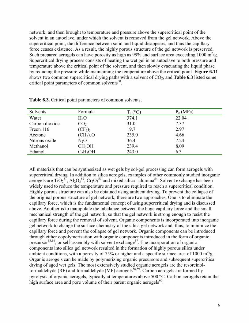
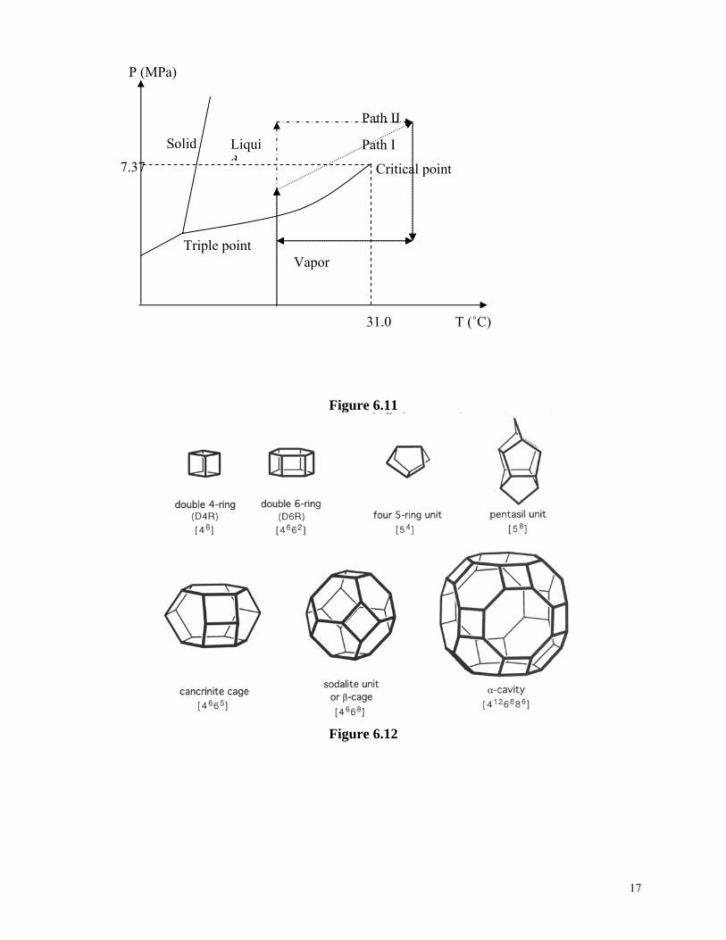
network, and then brought to temperature and pressure above the supercritical point of the solvent in an autoclave, under which the solvent is removed from the gel network. Above the supercritical point, the difference between solid and liquid disappears, and thus the capillary force ceases existence. As a result, the highly porous structure of the gel network is preserved. Such prepared aerogels can have porosity as high as 99% and surface area exceeding 1000 m2/g. Supercritical drying process consists of heating the wet gel in an autoclave to both pressure and temperature above the critical point of the solvent, and then slowly evacuating the liquid phase by reducing the pressure while maintaining the temperature above the critical point. Figure 6.11 shows two common supercritical drying paths with a solvent of CO2, and Table 6.3 listed some critical point parameters of common solvents50. Table 6.3. Critical point parameters of common solvents. Solvents Formula Tc (°C) Pc (MPa) Water Carbon dioxide Freon 116 Acetone Nitrous oxide Methanol Ethanol
H2O CO2(CF3)2(CH3)2O N2O CH3OH C2H5OH
374.1 31.0 19.7 235.0 36.4 239.4 243.0
22.04 7.37 2.97 4.66 7.24 8.09 6.3
All materials that can be synthesized as wet gels by sol-gel processing can form aerogels with supercritical drying. In addition to silica aerogels, examples of other commonly studied inorganic aerogels are TiO2
51, Al2 3O 52, Cr2 3O 53 and mixed silica –alumina54. Solvent exchange has been widely used to reduce the temperature and pressure required to reach a supercritical condition. Highly porous structure can also be obtained using ambient drying. To prevent the collapse of the original porous structure of gel network, there are two approaches. One is to eliminate the capillary force, which is the fundamental concept of using supercritical drying and is discussed above. Another is to manipulate the inbalance between the huge capillary force and the small mechanical strength of the gel network, so that the gel network is strong enough to resist the capillary force during the removal of solvent. Organic components is incorporated into inorganic gel network to change the surface chemistry of the silica gel network and, thus, to minimize the capillary force and prevent the collapse of gel network. Organic components can be introduced through either copolymerization with organic components introduced in the form of organic precursor55,56, or self-assembly with solvent exchange57. The incorporation of organic components into silica gel network resulted in the formation of highly porous silica under ambient conditions, with a porosity of 75% or higher and a specific surface area of 1000 m /g. Organic aerogels can be made by polymerizing organic precursors and subsequent supercritical drying of aged wet gels. The most extensively studied organic aerogels are the resorcinol-formaldehyde (RF) and formaldehyde (MF) aerogels
2
58,59. Carbon aerogels are formed by pyrolysis of organic aerogels, typically at temperatures above 500 °C. Carbon aerogels retain the high surface area and pore volume of their parent organic aerogels . 60
6
6.3.3. Crystalline Microporous Materials: Zeolites Zeolites are crystalline aluminosilicates and were first discovered in 175661,62. There are 34 naturally occurring zeolites and nearly 100 synthetic types zeolites. A zeolite has a three-dimensional framework structure with uniformly sized pores of molecular dimensions, typically ranging from ~ 0.3 to 1 nm in diameter, and pore volumes vary from about 0.1 to 0.35 cc/g. Zeolites have a broad diverse spectrum of applications, and examples include catalysts, adsorbents, and molecular sieves. Many review articles and books have been published63, ,64 65. Details of the structures and specific names of various zeolites have been summarized in literature6667,68. Only a brief description is given below. Zeolites are tectoaluminosilicates with a formal composition M2/nO.Al2O3.xSiO2.yH2O (n = valence state of the mobile cation, Mn+ and x ≥2), in that they composed of TO4 tetrahedra (T = tetrahedral atom, i.e., Si, Al), each oxygen atom is shared between adjacent tetrahedral, which leads to the framework ratio of O/T being equal to 2 for all zeolites69. A dimensional framework is formed by 4-corner connecting TO4 tetrahedra. When a zeolite is made of pure silica without any defects, each oxygen atom at the corner is shared by two SiO4 tetrahedra and charge is balanced. When silicon is replaced by aluminum, alkali metal ions, such as K+, Na+, alkaline earth ions, such as Ba2+, Ca2+, and protons, H+ are typically introduced to balance the charges. Such formed framework is relatively open and characterized by the presence of channels and cavities. The size of the pores and the dimensionality of the channel system are determined by arrangement of TO4 tetrahedra. More specifically, the pore sizes are determined by the size of the rings that are formed by connecting various numbers of TO4 tetrahedra or T atoms. An 8-ring is designated to a ring comprised of 8 TO4 tetrahedra and is considered to be a small pore opening (0.41 nm in diameter), a 10-ring a medium one (0.55 nm), and a 12-ring a large one (0.74 nm), when rings are free of distortion. Depending on the arrangement or the connection of various rings, different structures or pore openings, such as cages, channels, chains, and sheets, can be formed. Figure 6.12 shows some of these subunits, in which each cross point is designated to a TO4 tetrahedron for clarity. In this figure, the designations in terms of the n-rings defining the faces of these subunits are also included. For example, a cancrinite cage subunit is defined by six 4-rings and five 6-rings, and is thus designated a [4665] cage. A nomenclature similar to that used for cages has also been developed to describe channels, chains, and sheets. Different frameworks are formed by stacking various subunits and/or with different stacking sequences. There are 133 confirmed zeolite framework types. Figure 6.13 shows two schematics of zeolite frameworks: SOD and LTA framework types. Zeolites are normally prepared by hydrothermal synthesis techniques70,71. A typical synthesis procedure involves the use of water, a silica source, an alumina source, a mineralizing agent, and a structure-directing agent. The sources of silica are numerous and include colloidal silica, fumed silica, precipitated silica, and silicon alkoxides. Typical alumina sources include sodium aluminate, boehmite, aluminum hydroxide, aluminum nitrate, and alumina. The typical mineralizing agent is hydroxyl ion, OH-, and fluorine ion, F-. The structure-directing agent is a soluble organic species, such as quaternary ammonium ion, which assists in the formation of the silica framework and ultimately resides within the intracrystalline voids. Alkali metal ions can also play a structure-directing role in the crystallization process. Table 6.4 lists the reactants,
7
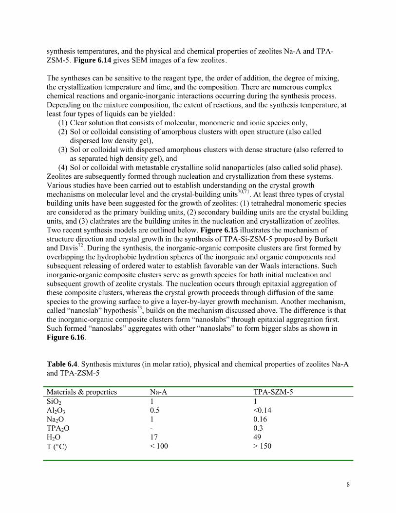
synthesis temperatures, and the physical and chemical properties of zeolites Na-A and TPA-ZSM-5. Figure 6.14 gives SEM images of a few zeolites. The syntheses can be sensitive to the reagent type, the order of addition, the degree of mixing, the crystallization temperature and time, and the composition. There are numerous complex chemical reactions and organic-inorganic interactions occurring during the synthesis process. Depending on the mixture composition, the extent of reactions, and the synthesis temperature, at least four types of liquids can be yielded:
(1) Clear solution that consists of molecular, monomeric and ionic species only, (2) Sol or colloidal consisting of amorphous clusters with open structure (also called
dispersed low density gel), (3) Sol or colloidal with dispersed amorphous clusters with dense structure (also referred to
as separated high density gel), and (4) Sol or colloidal with metastable crystalline solid nanoparticles (also called solid phase).
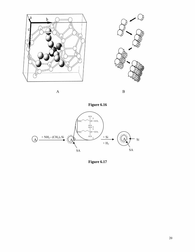
Zeolites are subsequently formed through nucleation and crystallization from these systems. Various studies have been carried out to establish understanding on the crystal growth mechanisms on molecular level and the crystal-building units70,71. At least three types of crystal building units have been suggested for the growth of zeolites: (1) tetrahedral monomeric species are considered as the primary building units, (2) secondary building units are the crystal building units, and (3) clathrates are the building unites in the nucleation and crystallization of zeolites. Two recent synthesis models are outlined below. Figure 6.15 illustrates the mechanism of structure direction and crystal growth in the synthesis of TPA-Si-ZSM-5 proposed by Burkett and Davis72. During the synthesis, the inorganic-organic composite clusters are first formed by overlapping the hydrophobic hydration spheres of the inorganic and organic components and subsequent releasing of ordered water to establish favorable van der Waals interactions. Such inorganic-organic composite clusters serve as growth species for both initial nucleation and subsequent growth of zeolite crystals. The nucleation occurs through epitaxial aggregation of these composite clusters, whereas the crystal growth proceeds through diffusion of the same species to the growing surface to give a layer-by-layer growth mechanism. Another mechanism, called “nanoslab” hypothesis73, builds on the mechanism discussed above. The difference is that the inorganic-organic composite clusters form “nanoslabs” through epitaxial aggregation first. Such formed “nanoslabs” aggregates with other “nanoslabs” to form bigger slabs as shown in Figure 6.16 . Table 6.4. Synthesis mixtures (in molar ratio), physical and chemical properties of zeolites Na-A and TPA-ZSM-5 Materials & properties Na-A TPA-SZM-5 SiO2Al2O3Na2O TPA2O H2O T (°C)
1 0.5 1 - 17 < 100
1 <0.14 0.16 0.3 49 > 150
8
Pore structure Density (g/cm3) Pore volume (cm3/g) Lattice stabilization Si/Al ratio Bronsted activity Affinity
3D, cages linked via windows 1.28 0.37 Na+, H2O 1 Low Hydrophilic
2D, intersecting channels 1.77 0.18 TPA+
0.12 High Hydrophobic
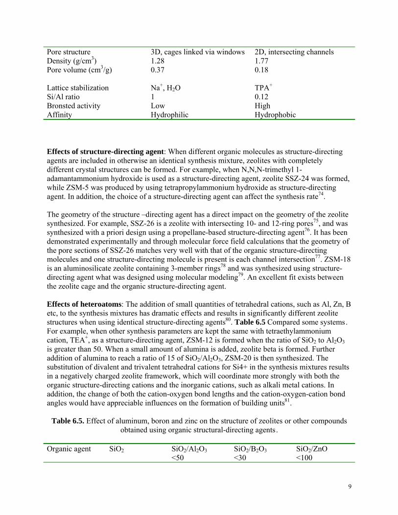
Effects of structure-directing agent: When different organic molecules as structure-directing agents are included in otherwise an identical synthesis mixture, zeolites with completely different crystal structures can be formed. For example, when N,N,N-trimethyl 1-adamantammonium hydroxide is used as a structure-directing agent, zeolite SSZ-24 was formed, while ZSM-5 was produced by using tetrapropylammonium hydroxide as structure-directing agent. In addition, the choice of a structure-directing agent can affect the synthesis rate74. The geometry of the structure –directing agent has a direct impact on the geometry of the zeolite synthesized. For example, SSZ-26 is a zeolite with intersecting 10- and 12-ring pores75, and was synthesized with a priori design using a propellane-based structure-directing agent76. It has been demonstrated experimentally and through molecular force field calculations that the geometry of the pore sections of SSZ-26 matches very well with that of the organic structure-directing molecules and one structure-directing molecule is present is each channel intersection77. ZSM-18 is an aluminosilicate zeolite containing 3-member rings78 and was synthesized using structure-directing agent what was designed using molecular modeling79. An excellent fit exists between the zeolite cage and the organic structure-directing agent. Effects of heteroatoms: The addition of small quantities of tetrahedral cations, such as Al, Zn, B etc, to the synthesis mixtures has dramatic effects and results in significantly different zeolite structures when using identical structure-directing agents80. Table 6.5 Compared some systems. For example, when other synthesis parameters are kept the same with tetraethylammonium cation, TEA+, as a structure-directing agent, ZSM-12 is formed when the ratio of SiO2 to Al2O3 is greater than 50. When a small amount of alumina is added, zeolite beta is formed. Further addition of alumina to reach a ratio of 15 of SiO2/Al2O3, ZSM-20 is then synthesized. The substitution of divalent and trivalent tetrahedral cations for Si4+ in the synthesis mixtures results in a negatively charged zeolite framework, which will coordinate more strongly with both the organic structure-directing cations and the inorganic cations, such as alkali metal cations. In addition, the change of both the cation-oxygen bond lengths and the cation-oxygen-cation bond angles would have appreciable influences on the formation of building units81.
Table 6.5. Effect of aluminum, boron and zinc on the structure of zeolites or other compounds obtained using organic structural-directing agents.
Organic agent SiO2 SiO2/Al2O3
<50 SiO2/B2O3<30
SiO2/ZnO <100
9
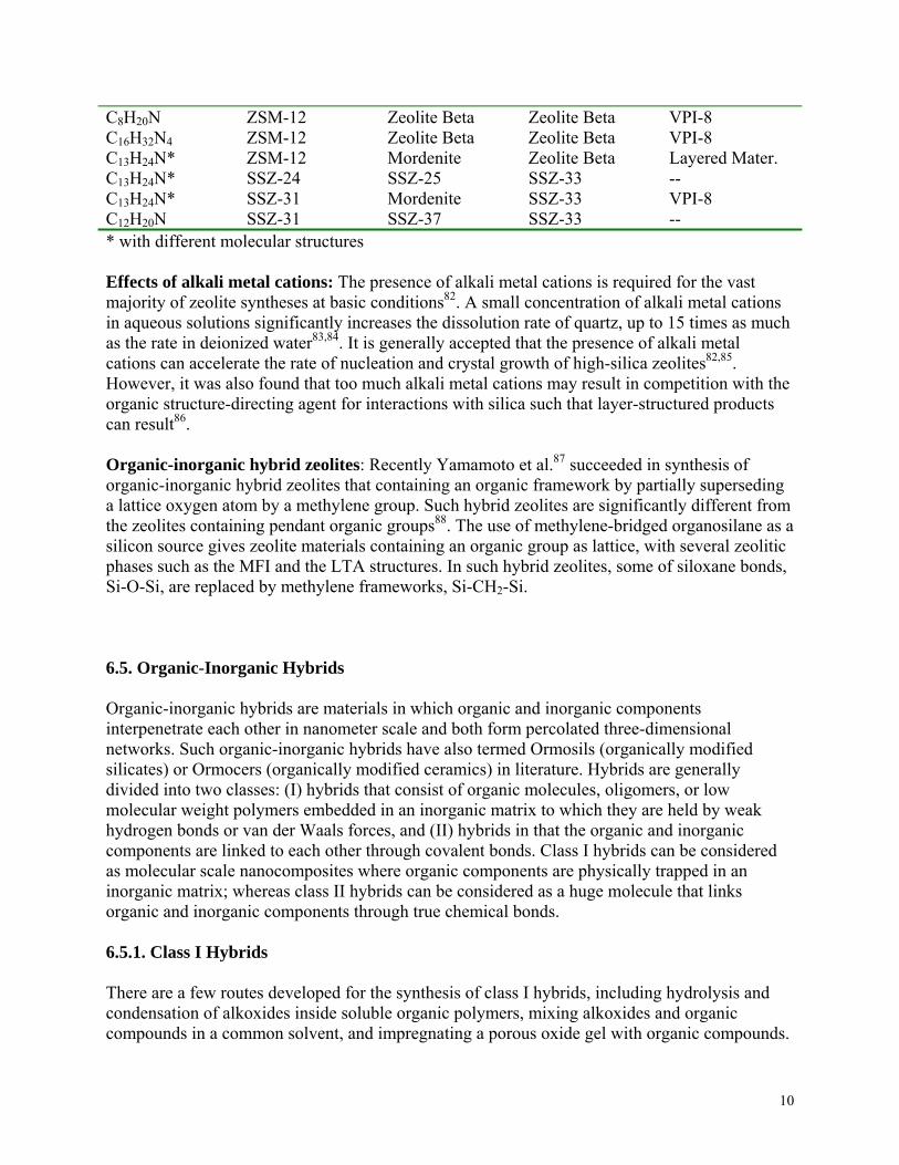
C8H20N C16H32N4C13H24N* C13H24N* C13H24N* C12H20N
ZSM-12 ZSM-12 ZSM-12 SSZ-24 SSZ-31 SSZ-31
Zeolite Beta Zeolite Beta Mordenite SSZ-25 Mordenite SSZ-37
Zeolite Beta Zeolite Beta Zeolite Beta SSZ-33 SSZ-33 SSZ-33
VPI-8 VPI-8 Layered Mater. -- VPI-8 --
* with different molecular structures Effects of alkali metal cations: The presence of alkali metal cations is required for the vast majority of zeolite syntheses at basic conditions82. A small concentration of alkali metal cations in aqueous solutions significantly increases the dissolution rate of quartz, up to 15 times as much as the rate in deionized water83,84. It is generally accepted that the presence of alkali metal cations can accelerate the rate of nucleation and crystal growth of high-silica zeolites82,85. However, it was also found that too much alkali metal cations may result in competition with the organic structure-directing agent for interactions with silica such that layer-structured products can result86. Organic-inorganic hybrid zeolites: Recently Yamamoto et al.87 succeeded in synthesis of organic-inorganic hybrid zeolites that containing an organic framework by partially superseding a lattice oxygen atom by a methylene group. Such hybrid zeolites are significantly different from the zeolites containing pendant organic groups88. The use of methylene-bridged organosilane as a silicon source gives zeolite materials containing an organic group as lattice, with several zeolitic phases such as the MFI and the LTA structures. In such hybrid zeolites, some of siloxane bonds, Si-O-Si, are replaced by methylene frameworks, Si-CH2-Si. 6.5. Organic-Inorganic Hybrids Organic-inorganic hybrids are materials in which organic and inorganic components interpenetrate each other in nanometer scale and both form percolated three-dimensional networks. Such organic-inorganic hybrids have also termed Ormosils (organically modified silicates) or Ormocers (organically modified ceramics) in literature. Hybrids are generally divided into two classes: (I) hybrids that consist of organic molecules, oligomers, or low molecular weight polymers embedded in an inorganic matrix to which they are held by weak hydrogen bonds or van der Waals forces, and (II) hybrids in that the organic and inorganic components are linked to each other through covalent bonds. Class I hybrids can be considered as molecular scale nanocomposites where organic components are physically trapped in an inorganic matrix; whereas class II hybrids can be considered as a huge molecule that links organic and inorganic components through true chemical bonds. 6.5.1. Class I Hybrids There are a few routes developed for the synthesis of class I hybrids, including hydrolysis and condensation of alkoxides inside soluble organic polymers, mixing alkoxides and organic compounds in a common solvent, and impregnating a porous oxide gel with organic compounds.
10
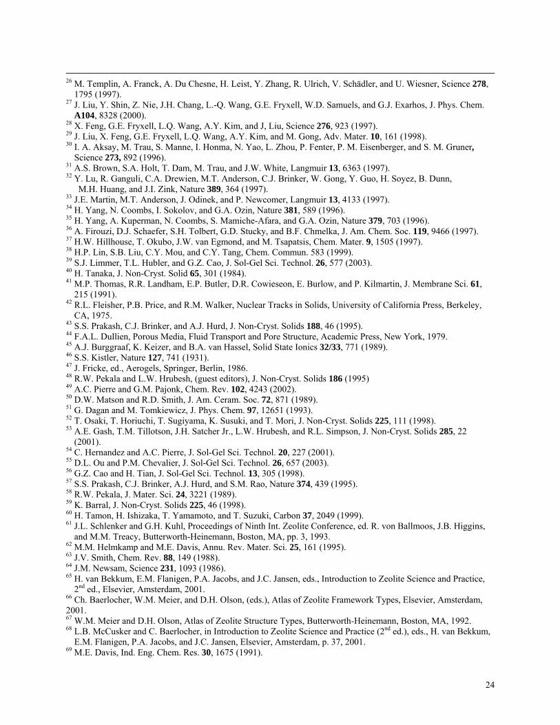
All three techniques have been widely explored for the formation of various organic-inorganic hybrids. For example, hybrids comprising organic dyes embedded in inorganic sol-gel derived matrix, such as silica, aluminosilicate, and transition metal oxides89,90, composed of polymers in inorganic matrix, such as poly(N-vinyl pyrrolidone) -silica91 and poly (methylmethacrylate)-silica92 are made by hydrolysis-condensation of alkoxides inside soluble organic polymers. Simultaneous gelation of the organic and inorganic components by mixing alkoxides and organic components in a common solvent is a method to ensure the formation of interpenetrated three-dimensional networks of both organic and inorganic components. However, the challenge is to prevent phase segregation and precipitation of organic components during hydrolysis and condensation processing, some precursor modification is desired93. Various silica-based hybrids with organics including polyparaphenylene and polyaniline were synthesized using this approach94. Infiltration of organic components into highly porous inorganic gel networks is yet another method to make class I hybrids such as PMMA-silica95. Ordered hybrids can also be made by intercalation of organic compounds in ordered inorganic hosts, which include clay silicates, metal phosphates, layered metal oxides, halides or chalcogenides96. For example alkyl amines can be intercalated in between vanadium oxide layers that was made by hydrolyzing and condensing VO(OPrn)3 in –n-propanol97. Intercalating materials will be discussed further later in section 6.6. 6.5.2. Class II Hybrids Class II hybrids comprise organic and inorganic components chemically bonded with each other and truly differ from organic-inorganic nanocomposites. In general, such hybrids are synthesized by hydrolyzing and polymerizing organic and inorganic precursors simultaneously. Inorganic precursors are referred to inorganic salts, such as SiCl4 and ErCl3, organic salts, such as Cd(acac)2, and alkoxides, such as Al(OR)3 and Ti(OR)4 where R is alkyl group. All the coordination groups associated with the metal cations in inorganic precursors are hydrolysable, i.e., readily replaceable by hydroxyl and/or oxo groups during hydrolysis and condensation process. Organic precursors consist of at least one unhydrolyzable coordination group and examples are Si(OR)3R’ and Si(OR)2R’2, which are also known as organoalkoxysilanes. Such unhydrolyzable organic groups are referred to as pendant organic groups. For organoalkoxysilanes, no three dimensional network would be formed if there are more than one pendant organic groups attached to each silicon atom. There are other forms of organic precursors in which unhydrolyzable organic groups bridge two silicon atoms. Such organic groups are referred to as bridge groups. Examples of such organoalkoxysilanes are given in Figure 6.2298,99. Since metal-carbon bonds are very stable during sol-gel processing and unhydrolyzable, the organic group R’ associated with the precursors will be incorporated into inorganic sol-gel network directly together with the metal cations. Typical hydrolysis and condensation reactions in the formation of such hybrids can be described as follows, taking silica-based hybrids as an example: Si(OR)4 + 4 H2O === (Si(OH)4 + 4 HOR (1) Si(OR)3R’ + 3 H2O === Si(OH)3R’ + 3 HOR (2)
11
Si(OH)4 + Si(OH)3R’ === (HO)3Si – O – Si (OH)2R’ (3) Si(OH)3R’+ Si(OH)3R’ === R’(HO)2Si – O – Si (OH)2R’ (4) It should be noted that although organoalkoxysilanes are the most useful and widely used family of organometallics for the synthesis of hybrid oxide-organic materials, other organometallics are also synthesized and used for the synthesis of organic-inorganic hybrids by co-condensation100. For example, butenyl chains were linked to Sn atom directly with C-Sn bonds. The incorporation of organic components into inorganic matrix through either physical trapping or chemical bonding not only introduces and modifies various physical properties. The presence of organic components would also exert appreciable influences on the sol-gel processing and the resultant microstructures. Organic groups may have catalytic effects to promote hydrolysis and condensation reactions. Long-chained organic ligands may also introduce steric diffusion barrier or increase the viscosity of the sol, resulting in a diffusion-limited process. Depending on the nature and amount of organic components introduced into the systems, highly porous101 or relatively dense hybrids102,103 can be prepared without subjecting to heat-treatment at elevated temperatures. Some unique microstructures can also be obtained by combining both highly pore and relative dense structures104. Although almost all the organic-inorganic hybrids are made through hydrolysis-condensation process, it has been demonstrated that non-hydrolytic sol-gel process is also capable of synthesizing hybrids105. Organic-inorganic hybrids with ordered nanostructures can be easily achieved by evaporation-induced self-assembly as demonstrated by Brinker and his coworkers106, , ,107 108 109.
Figures:
γ0
Surface active solutes
Organic solutes
Electrolytes γ
Surf
ace
tens
ion
c.m.c. C2
Figure 6.7
12
C
Hydrophobic tail
Hydrophilic head
Anionic srrfactant molecule
+ +
+ +
+
+
+ +
+
Counterion
Hydrophobic tail Hydrophilic head
A
B D
Figure 6.8
13
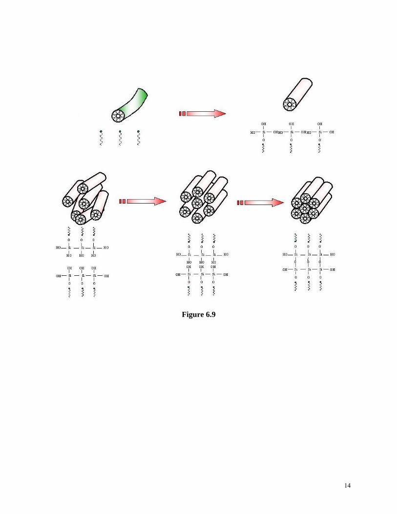
Figure 6.9
14

15
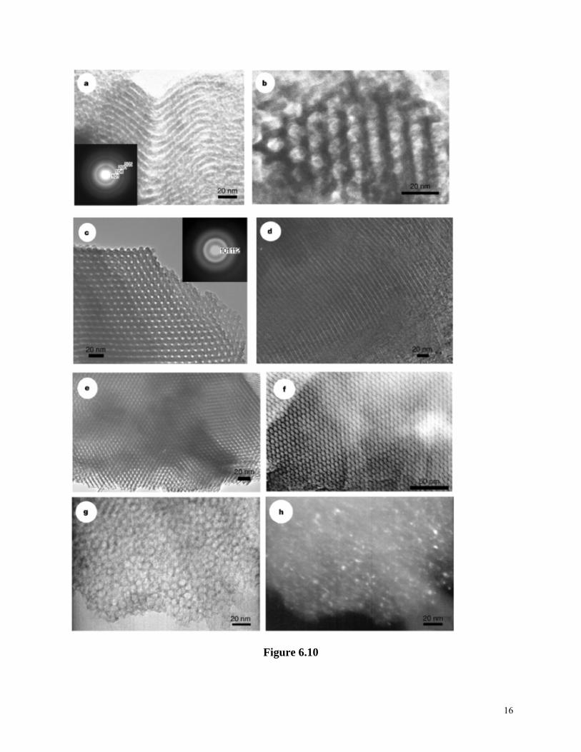
Figure 6.10
16
P (MPa)
Path II
Solid Liquid
Vapor
oint
Path I
Triple p
Critical point 7.37
31.0 T (˚C)
Figure 6.11
Figure 6.12
17
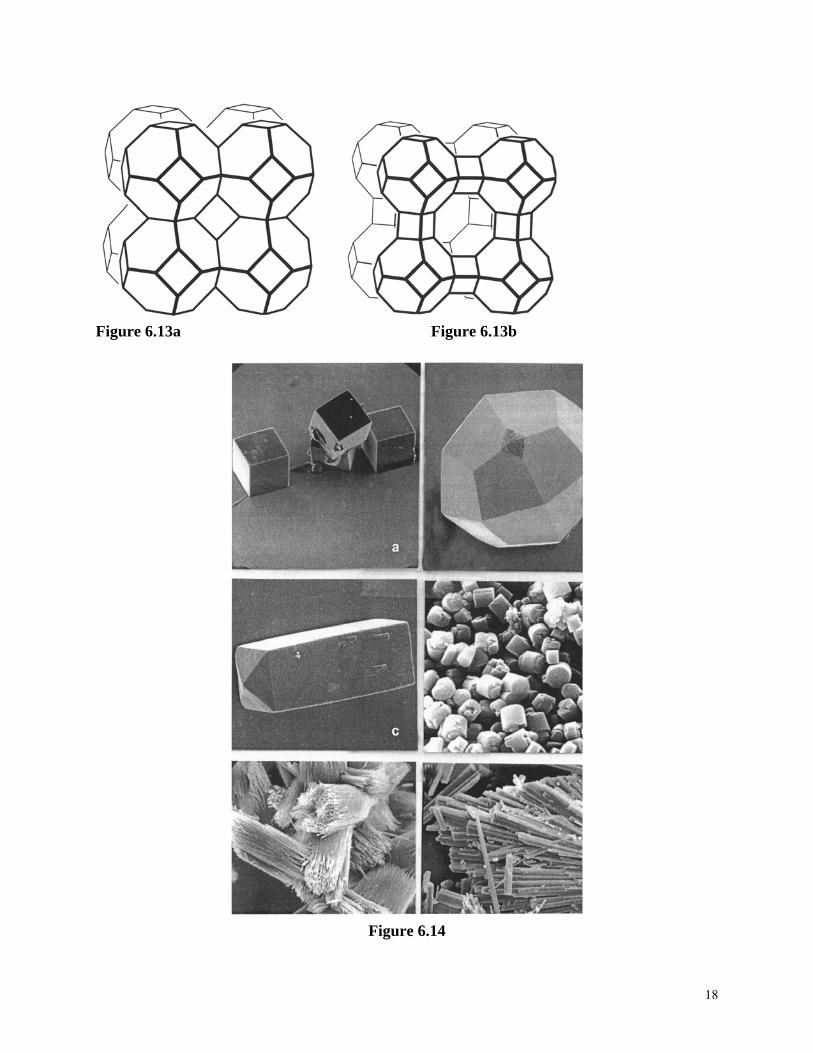
Figure 6.13a Figure 6.13b
Figure 6.14
18
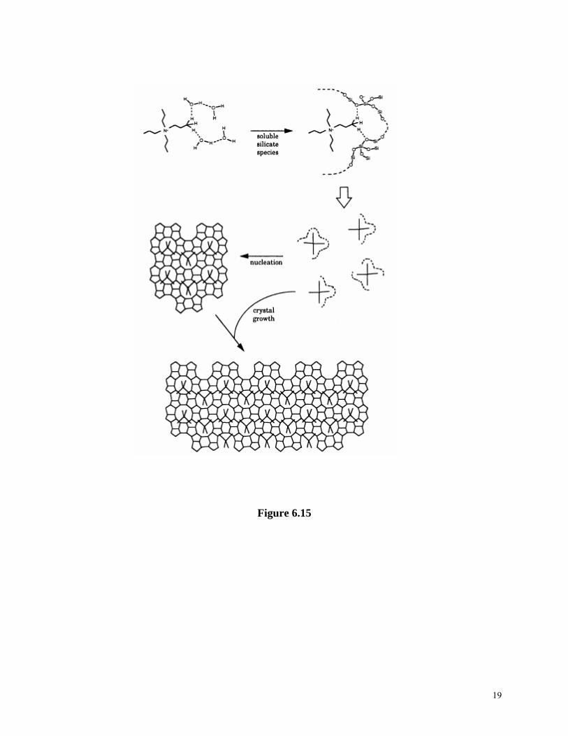
Figure 6.15
19
A B
Figure 6.16
+ Si
+ H2
A
NH3 SiH OCH3
OCH
OCH
NH3 SiH OCH3
OCH
OCH3
33
3
A + NH2 - (CH2)3 Si
A Si SASA
Figure 6.17
20
Figure 6.18
Figure 6.19
21
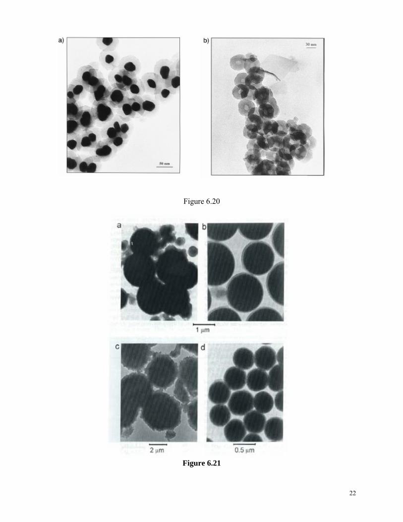
Figure 6.20
Figure 6.21
22
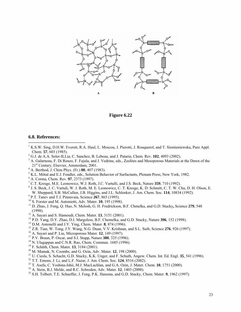
Figure 6.22 6.8. References: 1 K.S.W. Sing, D.H.W. Everett, R.A. Haul, L. Moscou, J. Pierotti, J. Rouquerol, and T. Siemieniewska, Pure Appl.
Chem. 57, 603 (1985). 2 G.J. de A.A. Soler-ILLia, C. Sanchez, B. Lebeau, and J. Patarin, Chem. Rev. 102, 4093 (2002). 3 A. Galarneau, F. Di Renzo, F. Fajula, and J. Vedrine, eds., Zeolites and Mesoporous Materials at the Dawn of the
21st Century, Elsevier, Amsterdam, 2001. 4 A. Berthod, J. Chim Phys. (Fr.) 80, 407 (1983). 5 K.L. Mittal and E.J. Fendler, eds., Solution Behavior of Surfactants, Plenum Press, New York, 1982. 6 A. Corma, Chem. Rev. 97, 2373 (1997). 7 C.T. Kresge, M.E. Leonowicz, W.J. Roth, J.C. Vartulli, and J.S. Beck, Nature 359, 710 (1992). 8 J. S. Beck, J. C. Vartuli, W. J. Roth, M. E. Leonowicz, C. T. Kresge, K. D. Schmitt, C. T. W. Chu, D. H. Olson, E.
W. Sheppard, S.B. McCullen, J.B. Higgins, and J.L. Schlenker, J. Am. Chem. Soc. 114, 10834 (1992). 9 P.T. Tanev and T.J. Pinnavaia, Science 267, 865 (1995). 10 S. Forster and M. Antonietti, Adv. Mater. 10, 195 (1998). 11 D. Zhao, J. Feng, Q. Huo, N. Melosh, G. H. Fredrickson, B.F. Chmelka, and G.D. Stucky, Science 279, 548
(1998). 12 A. Sayari and S. Hamoudi, Chem. Mater. 13, 3151 (2001). 13 P.D. Yang, D.Y. Zhao, D.I. Margoless, B.F. Chemelka, and G.D. Stucky, Nature 396, 152 (1998). 14 D.M. Antonelli and J.Y. Ying, Chem. Mater. 8, 874 (1996). 15 Z.R. Tian, W. Tong, J.Y. Wang, N.G. Duan, V.V. Krishnan, and S.L. Suib, Science 276, 926 (1997). 16 A. Sayari and P. Liu, Microporous Mater. 12, 149 (1997). 17 P.V. Braun, P. Oscar, and S.I. Stupp, Nature 380, 325 (1996). 18 N. Ulagappan and C.N.R. Rao, Chem. Commun. 1685 (1996). 19 F. Schüth, Chem. Mater. 13, 3184 (2001). 20 M. Mamak, N. Coombs, and G. Ozin, Adv. Mater. 12, 198 (2000). 21 U. Ciesla, S. Schacht, G.D. Stucky, K.K. Unger, and F. Schuth, Angew. Chem. Int. Ed. Engl. 35, 541 (1996). 22 T.T. Emons, J. Li, and L.F. Nazar, J. Am. Chem. Soc. 124, 8516 (2002). 23 T. Asefa, C. Yoshina-Ishii, M.J. MacLachlan, and G.A. Ozin, J. Mater. Chem. 10, 1751 (2000). 24 A. Stein, B.J. Melde, and R.C. Schroden, Adv. Mater. 12, 1403 (2000). 25 S.H. Tolbert, T.E. Schaeffer, J. Feng, P.K. Hansma, and G.D. Stucky, Chem. Mater. 9, 1962 (1997).
23
26 M. Templin, A. Franck, A. Du Chesne, H. Leist, Y. Zhang, R. Ulrich, V. Schädler, and U. Wiesner, Science 278,
1795 (1997). 27 J. Liu, Y. Shin, Z. Nie, J.H. Chang, L.-Q. Wang, G.E. Fryxell, W.D. Samuels, and G.J. Exarhos, J. Phys. Chem.
A104, 8328 (2000). 28 X. Feng, G.E. Fryxell, L.Q. Wang, A.Y. Kim, and J, Liu, Science 276, 923 (1997). 29 J. Liu, X. Feng, G.E. Fryxell, L.Q. Wang, A.Y. Kim, and M. Gong, Adv. Mater. 10, 161 (1998). 30 I. A. Aksay, M. Trau, S. Manne, I. Honma, N. Yao, L. Zhou, P. Fenter, P. M. Eisenberger, and S. M. Gruner,
Science 273, 892 (1996). 31 A.S. Brown, S.A. Holt, T. Dam, M. Trau, and J.W. White, Langmuir 13, 6363 (1997). 32 Y. Lu, R. Ganguli, C.A. Drewien, M.T. Anderson, C.J. Brinker, W. Gong, Y. Guo, H. Soyez, B. Dunn,
M.H. Huang, and J.I. Zink, Nature 389, 364 (1997). 33 J.E. Martin, M.T. Anderson, J. Odinek, and P. Newcomer, Langmuir 13, 4133 (1997). 34 H. Yang, N. Coombs, I. Sokolov, and G.A. Ozin, Nature 381, 589 (1996). 35 H. Yang, A. Kuperman, N. Coombs, S. Mamiche-Afara, and G.A. Ozin, Nature 379, 703 (1996). 36 A. Firouzi, D.J. Schaefer, S.H. Tolbert, G.D. Stucky, and B.F. Chmelka, J. Am. Chem. Soc. 119, 9466 (1997). 37 H.W. Hillhouse, T. Okubo, J.W. van Egmond, and M. Tsapatsis, Chem. Mater. 9, 1505 (1997). 38 H.P. Lin, S.B. Liu, C.Y. Mou, and C.Y. Tang, Chem. Commun. 583 (1999). 39 S.J. Limmer, T.L. Hubler, and G.Z. Cao, J. Sol-Gel Sci. Technol. 26, 577 (2003). 40 H. Tanaka, J. Non-Cryst. Solid 65, 301 (1984). 41 M.P. Thomas, R.R. Landham, E.P. Butler, D.R. Cowieseon, E. Burlow, and P. Kilmartin, J. Membrane Sci. 61,
215 (1991). 42 R.L. Fleisher, P.B. Price, and R.M. Walker, Nuclear Tracks in Solids, University of California Press, Berkeley,
CA, 1975. 43 S.S. Prakash, C.J. Brinker, and A.J. Hurd, J. Non-Cryst. Solids 188, 46 (1995). 44 F.A.L. Dullien, Porous Media, Fluid Transport and Pore Structure, Academic Press, New York, 1979. 45 A.J. Burggraaf, K. Keizer, and B.A. van Hassel, Solid State Ionics 32/33, 771 (1989). 46 S.S. Kistler, Nature 127, 741 (1931). 47 J. Fricke, ed., Aerogels, Springer, Berlin, 1986. 48 R.W. Pekala and L.W. Hrubesh, (guest editors), J. Non-Cryst. Solids 186 (1995) 49 A.C. Pierre and G.M. Pajonk, Chem. Rev. 102, 4243 (2002). 50 D.W. Matson and R.D. Smith, J. Am. Ceram. Soc. 72, 871 (1989). 51 G. Dagan and M. Tomkiewicz, J. Phys. Chem. 97, 12651 (1993). 52 T. Osaki, T. Horiuchi, T. Sugiyama, K. Susuki, and T. Mori, J. Non-Cryst. Solids 225, 111 (1998). 53 A.E. Gash, T.M. Tillotson, J.H. Satcher Jr., L.W. Hrubesh, and R.L. Simpson, J. Non-Cryst. Solids 285, 22
(2001). 54 C. Hernandez and A.C. Pierre, J. Sol-Gel Sci. Technol. 20, 227 (2001). 55 D.L. Ou and P.M. Chevalier, J. Sol-Gel Sci. Technol. 26, 657 (2003). 56 G.Z. Cao and H. Tian, J. Sol-Gel Sci. Technol. 13, 305 (1998). 57 S.S. Prakash, C.J. Brinker, A.J. Hurd, and S.M. Rao, Nature 374, 439 (1995). 58 R.W. Pekala, J. Mater. Sci. 24, 3221 (1989). 59 K. Barral, J. Non-Cryst. Solids 225, 46 (1998). 60 H. Tamon, H. Ishizaka, T. Yamamoto, and T. Suzuki, Carbon 37, 2049 (1999). 61 J.L. Schlenker and G.H. Kuhl, Proceedings of Ninth Int. Zeolite Conference, ed. R. von Ballmoos, J.B. Higgins,
and M.M. Treacy, Butterworth-Heinemann, Boston, MA, pp. 3, 1993. 62 M.M. Helmkamp and M.E. Davis, Annu. Rev. Mater. Sci. 25, 161 (1995). 63 J.V. Smith, Chem. Rev. 88, 149 (1988). 64 J.M. Newsam, Science 231, 1093 (1986). 65 H. van Bekkum, E.M. Flanigen, P.A. Jacobs, and J.C. Jansen, eds., Introduction to Zeolite Science and Practice,
2nd ed., Elsevier, Amsterdam, 2001. 66 Ch. Baerlocher, W.M. Meier, and D.H. Olson, (eds.), Atlas of Zeolite Framework Types, Elsevier, Amsterdam, 2001. 67 W.M. Meier and D.H. Olson, Atlas of Zeolite Structure Types, Butterworth-Heinemann, Boston, MA, 1992. 68 L.B. McCusker and C. Baerlocher, in Introduction to Zeolite Science and Practice (2nd ed.), eds., H. van Bekkum,
E.M. Flanigen, P.A. Jacobs, and J.C. Jansen, Elsevier, Amsterdam, p. 37, 2001. 69 M.E. Davis, Ind. Eng. Chem. Res. 30, 1675 (1991).
24
70 C.S. Cundy and P.A. Cox, Chem. Rev. 103, 663 (2003). 71 J.C. Jansen, in Introduction to Zeolite Science and Practice (2nd ed.), eds., H. van Bekkum, E.M. Flanigen, P.A.
Jacobs, and J.C. Jansen, Elsevier, Amsterdam, p.175, 2001. 72 S.L. Burkett and M.E. Davis, J. Phys. Chem. 98, 4647 (1994). 73 C.E.A. Kirschhock, R. Ravishankar, L. Van Looveren, P.A. Jacobs, and J.A. Martens, J. Phys. Chem. B103, 4972
(1999). 74 T.V. Harris and S.I. Zones, Stud. Surf. Sci. Catal. 94, 29 (1994). 75 S.I. Zones, M.M. Olmstead, and D.S. Santilli, J. Am. Chem. Soc. 114, 4195 (1992). 76 S.I. Zones, and D.S. Santilli, in Proc. Ninth Int. Zeolite Conf., ed. R. von Ballmoos, J.B. Higgins, and M.M.J.
Treacy, Butterworth-Heinemann, Boston, MA, p.171, 1993. 77 R.F. Lobo, M. Pan, I. Chan, S.I. Zones, P.A. Crozier, and M.E. Davis, J. Phys. Chem. 98, 12040 (1994). 78 S.L. Lawton and W.J. Rohrbaugh, Science 247, 1319 (1990). 79 K.D. Schmitt and G.J. Kennedy, Zeolites 14, 635 (1994). 80 R. Szostak, Handbook of Molecular Sieves, Van Nostrand Reinhold, New York, 1992. 81 C.A. Fyfe, H. Gies, G.T. Kokotailo, B. Marler, and D.E. Cox, J. Phys. Chem. 94, 3718 (1990). 82 M. Goepper, H.X. Li, and M.E. Davis, J. Chem. Soc. Chem. Commun. 22, 1665 (1992). 83 P.M. Dove and D.A. Crerar, Geochim. Cosmochim. Acta 54, 955 (1990). 84 P. Brady and J.V. Walther, Chem. Geol. 82, 253 (1990). 85 J.B. Higgins, in Reviews in Mineralogy: Silica Polymorphs, Vol 29, ed, P.H. Ribbe, the Mineral. Soc. Am.,
Washington, DC, 1994. 86 S.I. Zones, Microporous Mater. 2, 281 (1994). 87 K. Yamamoto, Y. Sakata, Y. Nohara, Y. Takahashi, and T. Tatsumi, Science 300, 470 (2003). 88 C.W. Jones, K. Tsuji, and M.E. Davis, Nature 393, 52 (1998) 89 D. Avnir, D. Levy, and R. Reisfeld, J. Phys. Chem. 88, 5956 (1984). 90 D. Levy, S. Einhorn, and D.J. Avnir, J. Non-Cryst. Solids 113, 137 (1989). 91 M. Toki, T.Y. Chow, T. Ohnaka, H. Samura, and T. Saegusa, Polym. Bull. 29, 653 (1992). 92 B.E. Yodas, J. Mater. Sci. 14, 1843 (1979). 93 B.M. Novak and C. Davies, Macromolecules 24, 5481 (1991). 94 F. Nishida, B. Dunn, E.T. Knobbe, P.D. Fuqua, R.B. Kaner, and B.R. Mattes, Mater. Res. Soc. Symp. Proc. 180,
747 (1990). 95 R. Reisfeld, D. Brusilovsky, M. Eyal, E. Miron, Z. Bursheim, and J. Ivri, Chem. Phys. Lett. 160, 43 (1989). 96 E. Ruiz-Hitchky, Adv. Mater. 5, 334 (1993). 97 N. Gharbi, C. Sanchez, J. Livage, J. Lemerle, L. Nejem, and J. Lefebvre, Inorg. Chem. 21, 2758 (1982). 98 K. Shea, D.A. Loy, and O. Webster, J. Am. Chem. Soc. 114, 6700 (1992). 99 R.J.P. Corriu, J.J.E. Moreau, P. Thepot, and C.M. Wong, Chem. Mater. 4, 1217 (1992). 100 C. Bonhomme, M. Henry, and J. Livage, J. Non-Cryst. Solids 159, 22 (1993). 101 W.G. Fahrenholtz, D.M. Smoth, and D.W. Hua, J. Non-Cryst. Solids 144, 45 (1992). 102 B. Yoldas, J. Sol-Gel Sci. Technol. 13, 147 (1998). 103 C.M. Chan, G.Z. Cao, H. Fong, M. Sarikaya, T. Robinson, and L. Nelson, J. Mater. Res. 15, 148 (2000). 104 S. Seraji, Y. Wu, M.J. Forbess, S.J. Limmer, T.P. Chou, and G.Z. Cao, Adv. Mater. 12, 1695 (2000). 105 J.N. Hay and H.M. Raval, Chem. Mater. 13, 3396 (2001). 106 C.J. Brinker, Y.F. Lu, A. Sellinger, and H.Y. Fan, Adv. Mater. 11, 579 (1999). 107 Y. Lu, R. Ganguli, C. Drewien, M. Anderson, C.J. Brinker, W. Gong, Y. Guo, H. Soyez, B. Dunn, M. Huang,
and J. Zink, Nature 389, 364 (1997). 108 A. Sellinger, P.M. Weiss, A. Nguyen, Y. Lu, R.A. Assink, W. Gong, and C.J. Brinker, Nature 394, 256 (1998). 109 Y. Lu, H. Fan, A. Stump, T.L. Ward, T. Rieker, and C.J. Brinker, Nature 398, 223 (1999).
25