60777, 60811, 60820 - c1.rt-static.com · lower shock absorber attaching bolts. 2. mark the upper...
TRANSCRIPT
MN
-219
• (
0990
1) •
EC
R 6
599
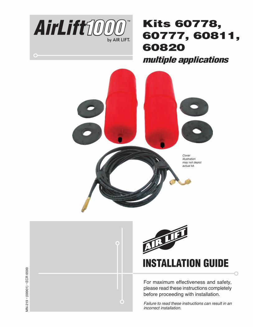
Cover illustration may not depict actual kit.
For maximum effectiveness and safety, please read these instructions completely before proceeding with installation.
Failure to read these instructions can result in an incorrect installation.
INSTALLATION GUIDE
Kits 60778, 60777, 60811, 60820multiple applications
™AirLift1000

Introduction . . . . . . . . . . . . . . . . . . . . . . . . . . . . . . . . . . . . . . . 2Important Safety Notice . . . . . . . . . . . . . . . . . . . . . . . . . . . . . . . . . . . . . . . . . . . . . 2Notation Explanation . . . . . . . . . . . . . . . . . . . . . . . . . . . . . . . . . . . . . . . . . . . . . . . . 2
Installing the Air Lift 1000 System . . . . . . . . . . . . . . . . . . . . . 3Getting Started . . . . . . . . . . . . . . . . . . . . . . . . . . . . . . . . . . . . . . . . . . . . . . . . . . . . 3Tee Air Line Routing . . . . . . . . . . . . . . . . . . . . . . . . . . . . . . . . . . . . . . . . . . . . . . . . 5Dual Air line Routing . . . . . . . . . . . . . . . . . . . . . . . . . . . . . . . . . . . . . . . . . . . . . . . . 7
Maintenance and Servicing . . . . . . . . . . . . . . . . . . . . . . . . . . 9Minimum and Maximum Pressure . . . . . . . . . . . . . . . . . . . . . . . . . . . . . . . . . . . . . . 9Maintenance Guidelines . . . . . . . . . . . . . . . . . . . . . . . . . . . . . . . . . . . . . . . . . . . . . 9
Frequently Asked Questions . . . . . . . . . . . . . . . . . . . . . . . . .10
Replacement Information . . . . . . . . . . . . . . . . . . . . . . . . . . . .11
Contact Information . . . . . . . . . . . . . . . . . . . . . . . . . . . . . . . .11
Warranty and Returns Policy . . . . . . . . . . . . . . . . . . . . . . . . .12
Template for use with Air Lift 1000 . . . . . . . . . . . . . . . . . . . .13
TABLE OF CONTENTS
1
MN-2192
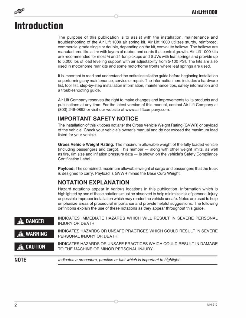
IntroductionThe purpose of this publication is to assist with the installation, maintenance and troubleshooting of the Air Lift 1000 air spring kit. Air Lift 1000 utilizes sturdy, reinforced, commercial grade single or double, depending on the kit, convolute bellows. The bellows are manufactured like a tire with layers of rubber and cords that control growth. Air Lift 1000 kits are recommended for most ¾ and 1 ton pickups and SUVs with leaf springs and provide up to 5,000 lbs of load leveling support with air adjustability from 5-100 PSI. The kits are also used in motorhome rear kits and some motorhome fronts where leaf springs are used.
It is important to read and understand the entire installation guide before beginning installation or performing any maintenance, service or repair. The information here includes a hardware list, tool list, step-by-step installation information, maintenance tips, safety information and a troubleshooting guide.
Air Lift Company reserves the right to make changes and improvements to its products and publications at any time. For the latest version of this manual, contact Air Lift Company at (800) 248-0892 or visit our website at www.airliftcompany.com.
IMPORTANT SAFETY NOTICEThe installation of this kit does not alter the Gross Vehicle Weight Rating (GVWR) or payload of the vehicle. Check your vehicle’s owner’s manual and do not exceed the maximum load listed for your vehicle.
Gross Vehicle Weight Rating: The maximum allowable weight of the fully loaded vehicle (including passengers and cargo). This number — along with other weight limits, as well as tire, rim size and inflation pressure data — is shown on the vehicle’s Safety Compliance Certification Label.
Payload: The combined, maximum allowable weight of cargo and passengers that the truck is designed to carry. Payload is GVWR minus the Base Curb Weight.
NOTATION EXPLANATIONHazard notations appear in various locations in this publication. Information which is highlighted by one of these notations must be observed to help minimize risk of personal injury or possible improper installation which may render the vehicle unsafe. Notes are used to help emphasize areas of procedural importance and provide helpful suggestions. The following definitions explain the use of these notations as they appear throughout this guide.
INDICATES IMMEDIATE HAZARDS WHICH WILL RESULT IN SEVERE PERSONAL INJURY OR DEATH.
INDICATES HAZARDS OR UNSAFE PRACTICES WHICH COULD RESULT IN SEVERE PERSONAL INJURY OR DEATH.
INDICATES HAZARDS OR UNSAFE PRACTICES WHICH COULD RESULT IN DAMAGE TO THE MACHINE OR MINOR PERSONAL INJURY.
Indicates a procedure, practice or hint which is important to highlight.
DANGER
NOTE
WARNING
CAUTION
AirLift1000

MN-219 3
Installing the Air Lift 1000 SystemGETTING STARTED
1. Jack up rear of vehicle or raise on hoist. Support frame with safety stands. Remove lower shock absorber attaching bolts.
2. Mark the upper spring seat and coil spring with a marker so as to index the spring back in the same position upon installation.
3. Lower the axle or raise the body of the vehicle until the suspension has extended far enough to remove the coil spring.
IT MAY BE NECESSARY TO UNBOLT THE BRAKE LINE HANGERS SO AS NOT TO PULL ON THE HOSE DURING THIS STEP. IT MAY ALSO BE NECESSARY TO UN-BOLT THE SWAY BAR TO GAIN ADDITIONAL CLEARANCE TO DROP THE AXLE FAR ENOUGH FOR THE LOWER SPRING SEAT ACCESS. NOTE: MOST SWAY BARS UNBOLT FROM THE AXLE, SOME MAY BE ATTACHED TO THE LOWER CON-TROL ARM.
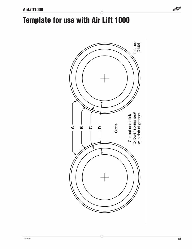
4. A 3/4” access hole must be made for the valve stem. Using the template on the last page, cut out the circle which best fits your model to center punch the lower spring seat for the hose/stem access. Drill a 3/4” hole, or enlarge the existing hole, in the center of the lower spring seat. Option: you can drill the hole out to 1/2” and grind larger as previously suggested. Remove all burrs and sharp edges (Figure 2).
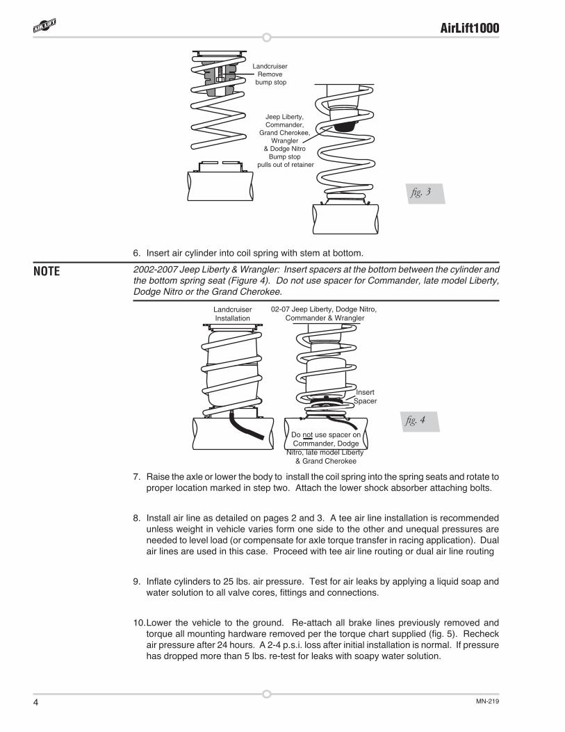
5. LANDCRUISER: using a socket and extension, remove the rubber bump stop from the upper spring seat and discard (fig. 3).
Jeep Liberty, Commander, Grand Cherokee, Wrangler and Dodge Nitro: pull jounce bumper out of cup (fig. 3).
NOTE
CAUTION
INCREASE HOLEDIAMETER TO 3/4"
fig. 2
AirLift1000
MN-2194
NOTE
6. Insert air cylinder into coil spring with stem at bottom.
2002-2007 Jeep Liberty & Wrangler: Insert spacers at the bottom between the cylinder and the bottom spring seat (Figure 4). Do not use spacer for Commander, late model Liberty, Dodge Nitro or the Grand Cherokee.
7. Raise the axle or lower the body to install the coil spring into the spring seats and rotate to proper location marked in step two. Attach the lower shock absorber attaching bolts.
8. Install air line as detailed on pages 2 and 3. A tee air line installation is recommended unless weight in vehicle varies form one side to the other and unequal pressures are needed to level load (or compensate for axle torque transfer in racing application). Dual air lines are used in this case. Proceed with tee air line routing or dual air line routing
9. Inflate cylinders to 25 lbs. air pressure. Test for air leaks by applying a liquid soap and water solution to all valve cores, fittings and connections.
10. Lower the vehicle to the ground. Re-attach all brake lines previously removed and torque all mounting hardware removed per the torque chart supplied (fig. 5). Recheck air pressure after 24 hours. A 2-4 p.s.i. loss after initial installation is normal. If pressure has dropped more than 5 lbs. re-test for leaks with soapy water solution.
LandcruiserRemove
bump stop
Jeep Liberty,Commander,
Grand Cherokee, Wrangler
& Dodge NitroBump stop
pulls out of retainer
fig. 3
02-07 Jeep Liberty, Dodge Nitro, Commander & Wrangler
LandcruiserInstallation
InsertSpacer
Do not use spacer on Commander, Dodge
Nitro, late model Liberty & Grand Cherokee
fig. 4
AirLift1000
MN-219 5
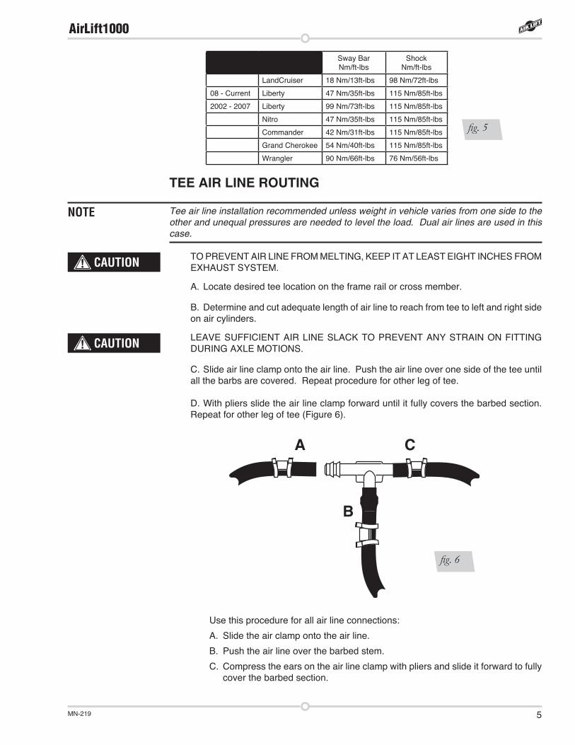
TEE AIR LINE ROUTING
Tee air line installation recommended unless weight in vehicle varies from one side to the other and unequal pressures are needed to level the load. Dual air lines are used in this case.
TO PREVENT AIR LINE FROM MELTING, KEEP IT AT LEAST EIGHT INCHES FROM EXHAUST SYSTEM.
A. Locate desired tee location on the frame rail or cross member.
B. Determine and cut adequate length of air line to reach from tee to left and right side on air cylinders.
LEAVE SUFFICIENT AIR LINE SLACK TO PREVENT ANY STRAIN ON FITTING DURING AXLE MOTIONS.
C. Slide air line clamp onto the air line. Push the air line over one side of the tee until all the barbs are covered. Repeat procedure for other leg of tee.
D. With pliers slide the air line clamp forward until it fully covers the barbed section. Repeat for other leg of tee (Figure 6).
NOTE
A
B
C
fig. 6
Use this procedure for all air line connections:
A. Slide the air clamp onto the air line.
B. Push the air line over the barbed stem.
C. Compress the ears on the air line clamp with pliers and slide it forward to fully cover the barbed section.
Sway Bar Nm/ft-lbs
Shock Nm/ft-lbs
LandCruiser 18 Nm/13ft-lbs 98 Nm/72ft-lbs
08 - Current Liberty 47 Nm/35ft-lbs 115 Nm/85ft-lbs
2002 - 2007 Liberty 99 Nm/73ft-lbs 115 Nm/85ft-lbs
Nitro 47 Nm/35ft-lbs 115 Nm/85ft-lbs
Commander 42 Nm/31ft-lbs 115 Nm/85ft-lbs
Grand Cherokee 54 Nm/40ft-lbs 115 Nm/85ft-lbs
Wrangler 90 Nm/66ft-lbs 76 Nm/56ft-lbs
fig. 5
CAUTION
CAUTION
AirLift1000

MN-2196
E. Route along cross member and either lower control arm or upper spring seat to air cylinder.
F. Insert air line through lower spring seat then slide on air line clamp.
G. Push the air line onto the stem, covering all the barbs. With pliers slide the air line clamp upward until it fully covers the barbed section (Figure 7).
H. Push the remaining air line over the last fitting on tee and route along frame to desired inflation valve location (Figure 7). Attach with plastic straps or wire.
I. Select a location for inflation valve in the gas cap well, the trunk, rear bumper, fender flange or behind the license plate, assuring that the valve will be protected and accessible with an air hose (Figure 8).
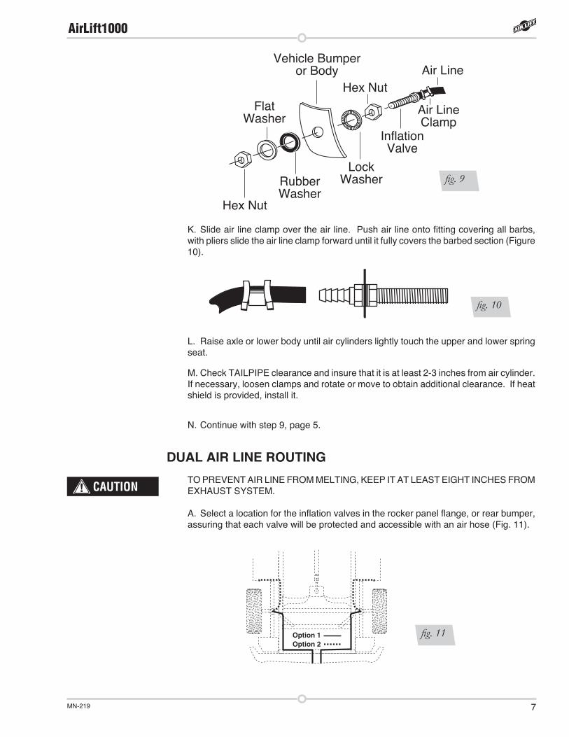
J. Drill a 5/16” hole for inflation valve and mount as in illustration (Figure 9). Rubber washer is for outside weather seal.
fig. 8
fig. 7
AirLift1000
MN-219 7
K. Slide air line clamp over the air line. Push air line onto fitting covering all barbs, with pliers slide the air line clamp forward until it fully covers the barbed section (Figure 10).
L. Raise axle or lower body until air cylinders lightly touch the upper and lower spring seat.
M. Check TAILPIPE clearance and insure that it is at least 2-3 inches from air cylinder. If necessary, loosen clamps and rotate or move to obtain additional clearance. If heat shield is provided, install it.
N. Continue with step 9, page 5.
DUAL AIR LINE ROUTINGTO PREVENT AIR LINE FROM MELTING, KEEP IT AT LEAST EIGHT INCHES FROM EXHAUST SYSTEM.
A. Select a location for the inflation valves in the rocker panel flange, or rear bumper, assuring that each valve will be protected and accessible with an air hose (Fig. 11).
CAUTION
Option 1Option 2
fig. 11
Hex Nut
RubberWasher
FlatWasher
LockWasher
Hex Nut
InflationValve
Air LineVehicle Bumper
or Body
Air LineClamp
fig. 9
fig. 10
AirLift1000
MN-2198
B. Determine and cut adequate length of air line to reach from valve location to left side air cylinder.
LEAVE SUFFICIENT AIR LINE SLACK TO PREVENT ANY STRAIN ON VALVE STEM DURING NORMAL AXLE MOTIONS.
C. Insert the air line through the lower spring seat.
D. Slide air line clamp onto the cut air line. Push the air line onto the stem, covering all the barbed section. With pliers slide the air line clamp forward until it fully covers barbed section (Figure 10).
E. Repeat process for right side.
F. Drill 5/16” hole for inflating valves and mount as illustrated. Rubber washer is for outside weather seal (Figure 9).
G. Route air line along control arm and frame to inflation valve location and cut off excess air line.
H. Slide air line clamp onto the air line and push the air line over the fitting, covering all the barbs. With pliers slide the air line clamp forward until it fully covers the barbed section.
I. Raise axle or lower body until air cylinders lightly touch the upper and lower spring seat.
J. Check TAILPIPE clearance and insure that it is at least 2-3 inches from air cylinders. If necessary, loosen clamps and rotate or move to obtain additional clearance. If heat shields are supplied, install them.
K. Continue with step 9, page 5.
DO NOT INFLATE AIR CYLINDERS BEFORE READING MAINTENANCE/OPERATION TIPS.
CAUTION
CAUTION
AirLift1000
MN-219 9
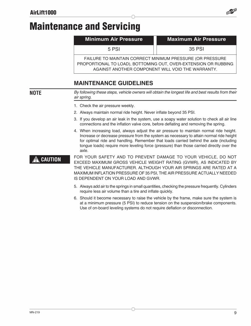
MAINTENANCE GUIDELINESBy following these steps, vehicle owners will obtain the longest life and best results from their air spring.
1. Check the air pressure weekly.
2. Always maintain normal ride height. Never inflate beyond 35 PSI.
3. If you develop an air leak in the system, use a soapy water solution to check all air line connections and the inflation valve core, before deflating and removing the spring.
4. When increasing load, always adjust the air pressure to maintain normal ride height. Increase or decrease pressure from the system as necessary to attain normal ride height for optimal ride and handling. Remember that loads carried behind the axle (including tongue loads) require more leveling force (pressure) than those carried directly over the axle.
FOR YOUR SAFETY AND TO PREVENT DAMAGE TO YOUR VEHICLE, DO NOT EXCEED MAXIMUM GROSS VEHICLE WEIGHT RATING (GVWR), AS INDICATED BY THE VEHICLE MANUFACTURER. ALTHOUGH YOUR AIR SPRINGS ARE RATED AT A MAXIMUM INFLATION PRESSURE OF 35 PSI, THE AIR PRESSURE ACTUALLY NEEDED IS DEPENDENT ON YOUR LOAD AND GVWR.
5. Always add air to the springs in small quantities, checking the pressure frequently. Cylinders require less air volume than a tire and inflate quickly.
6. Should it become necessary to raise the vehicle by the frame, make sure the system is at a minimum pressure (5 PSI) to reduce tension on the suspension/brake components. Use of on-board leveling systems do not require deflation or disconnection.
NOTE
CAUTION
Maintenance and Servicing
5 PSI 35 PSI
FAILURE TO MAINTAIN CORRECT MINIMUM PRESSURE (OR PRESSURE PROPORTIONAL TO LOAD), BOTTOMING OUT, OVER-EXTENSION OR RUBBING
AGAINST ANOTHER COMPONENT WILL VOID THE WARRANTY.
Maximum Air PressureMinimum Air Pressure
AirLift1000
MN-21910
Product UseFREQUENTLY ASKED QUESTIONSQ. Will installing air springs increase the weight ratings of a vehicle? No. Adding air springs will not change the weight ratings (GAWR, GCWR and/or GVWR)
of a vehicle. Exceeding the GVWR is dangerous and voids the Air Lift warranty.
Q. Is it necessary to keep air in the air springs at all times and how much pressure will they need?
The minimum air pressure should be maintained at all times. The minimum air pressure keeps the air spring in shape, ensuring that it will move throughout its travel without rubbing or wearing on itself.
Q. Is it necessary to add a compressor system to the air springs? No. Air pressure can be adjusted with any type of compressor as long as it can produce
sufficient pressure to service the springs. Even a bicycle tire pump can be used, but it’s a lot of work.
Q. How long should air springs last? If the air springs are properly installed and maintained they can last indefinitely.
Q. Will raising the vehicle on a hoist for service work damage the air springs? No. The vehicle can be lifted on a hoist for short-term service work such as tire rotation
or oil changes. However, if the vehicle will be on the hoist for a prolonged period of time, support the axle with jack stands in order to take the tension off of the air springs.
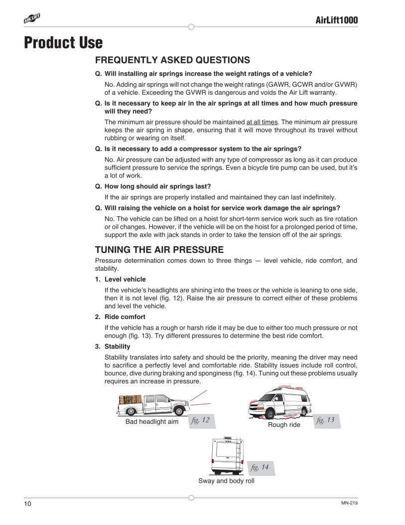
TUNING THE AIR PRESSUREPressure determination comes down to three things — level vehicle, ride comfort, and stability.
1. Level vehicle If the vehicle’s headlights are shining into the trees or the vehicle is leaning to one side,
then it is not level (fig. 12). Raise the air pressure to correct either of these problems and level the vehicle.
2. Ride comfort If the vehicle has a rough or harsh ride it may be due to either too much pressure or not
enough (fig. 13). Try different pressures to determine the best ride comfort.
3. Stability Stability translates into safety and should be the priority, meaning the driver may need
to sacrifice a perfectly level and comfortable ride. Stability issues include roll control, bounce, dive during braking and sponginess (fig. 14). Tuning out these problems usually requires an increase in pressure.
fig. 12 fig. 13Bad headlight aim Rough ride
Sway and body roll
fig. 14
AirLift1000
MN-219 11
GUIDELINES FOR ADDING AIR1. Start with the vehicle level or slightly above.
2. When in doubt, always add air.
3. For motorhomes, start with 50-100 PSI in the rear because it can be safely assumed that it is heavily loaded.
4. If the front of the vehicle dives while braking, increase the pressure in the front air bags, if equipped.
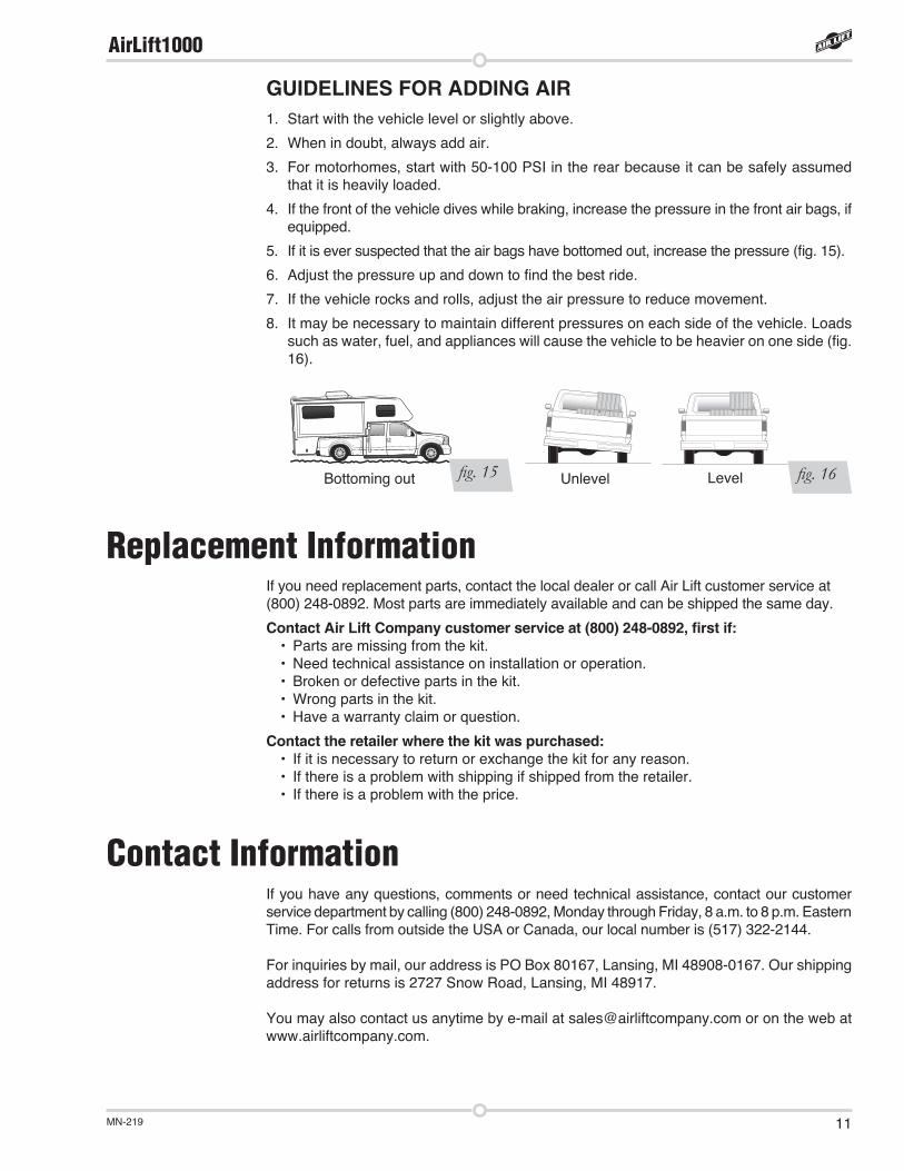
5. If it is ever suspected that the air bags have bottomed out, increase the pressure (fig. 15).
6. Adjust the pressure up and down to find the best ride.
7. If the vehicle rocks and rolls, adjust the air pressure to reduce movement.
8. It may be necessary to maintain different pressures on each side of the vehicle. Loads such as water, fuel, and appliances will cause the vehicle to be heavier on one side (fig. 16).
fig. 15 fig. 16Bottoming out Unlevel Level
Replacement InformationIf you need replacement parts, contact the local dealer or call Air Lift customer service at(800) 248-0892. Most parts are immediately available and can be shipped the same day.
Contact Air Lift Company customer service at (800) 248-0892, first if:• Parts are missing from the kit.• Need technical assistance on installation or operation.• Broken or defective parts in the kit.• Wrong parts in the kit.• Have a warranty claim or question.
Contact the retailer where the kit was purchased:• If it is necessary to return or exchange the kit for any reason.• If there is a problem with shipping if shipped from the retailer.• If there is a problem with the price.
Contact InformationIf you have any questions, comments or need technical assistance, contact our customer service department by calling (800) 248-0892, Monday through Friday, 8 a.m. to 8 p.m. Eastern Time. For calls from outside the USA or Canada, our local number is (517) 322-2144.
For inquiries by mail, our address is PO Box 80167, Lansing, MI 48908-0167. Our shipping address for returns is 2727 Snow Road, Lansing, MI 48917.
You may also contact us anytime by e-mail at [email protected] or on the web at www.airliftcompany.com.
AirLift1000

MN-21912
Air Lift Company warrants its products, for the time periods listed below, to the original retail purchaser against manufacturing defects when used on catalog-listed applications on cars, vans, light trucks and motorhomes under normal operating conditions for as long as Air Lift manufactures the product. The warranty does not apply to products that have been improperly applied, improperly installed, used in racing or off-road applications, used for commercial purposes, or which have not been maintained in accordance with installation instructions furnished with all products. The consumer will be responsible for removing (labor charges) the defective product from the vehicle and returning it, transportation costs prepaid, to the dealer from which it was purchased or to Air Lift Company for verification.
Air Lift will repair or replace, at its option, defective products or components. A minimum $10.00 shipping and handling charge will apply to all warranty claims. Before returning any defective product, you must call Air Lift at (800) 248-0892 in the U.S. and Canada (elsewhere, (517) 322-2144) for a Returned Materials Authorization (RMA) number. Returns to Air Lift can be sent to: Air Lift Company • 2727 Snow Road • Lansing, MI • 48917.
Product failures resulting from abnormal use or misuse are excluded from this warranty. The loss of use of the product, loss of time, inconvenience, commercial loss or consequential damages is not covered. The consumer is responsible for installation/reinstallation (labor charges) of the product. Air Lift Company reserves the right to change the design of any product without assuming any obligation to modify any product previously manufactured.
This warranty gives you specific legal rights and you may also have other rights that vary from state-to-state. Some states do not allow limitations on how long an implied warranty lasts or allow the exclusion or limitation of incidental or consequential damages. The above limitation or exclusion may not apply to you. There are no warranties, expressed or implied including any implied warranties of merchantability and fitness, which extend beyond this warranty period. There are no warranties that extend beyond the description on the face hereof. Seller disclaims the implied warranty of merchantability. (Dated proof of purchase required.)
Warranty and Returns Policy
Air Lift 1000 .................... Lifetime LimitedRideControl .................... Lifetime LimitedLoadLifter 5000*............. Lifetime Limited SlamAir ........................... Lifetime LimitedAirCell ............................. Lifetime LimitedLifestyle & Performance** .... 1 Year LimitedLoadController/Single ...... 2 Year Limited
LoadController/Dual ......... 2 Year LimitedLoad Controller (I) ............ 2 Year LimitedLoad Controller (II) ........... 2 Year LimitedSmartAir ............................ 2 Year LimitedWireless AIR...................... 2 Year LimitedWirelessONE ..................... 2 Year Limited Other Accessories ............ 2 Year Limited
*formerly SuperDuty**formerly LifeStyle & Perfromance and EasyStreet
AirLift1000
MN-219 13
Template for use with Air Lift 1000
A B C D
Circ
le
Cut
out
and
stic
kto
low
er s
prin
g se
atw
ith d
ab o
f gre
ase.
T-1
2-49
0(0
4806
)
A B C D
Circ
le
Cut
out
and
stic
kto
low
er s
prin
g se
atw
ith d
ab o
f gre
ase.
T-1
2-49
0(0
4806
)
A B C D
Circ
le
Cut
out
and
stic
kto
low
er s
prin
g se
atw
ith d
ab o
f gre
ase.
T-1
2-49
0(0
4806
)
AirLift1000
Air Lift Company • 2727 Snow Road • Lansing, MI 48917 or PO Box 80167 • Lansing, MI 48908-0167 Toll Free (800) 248-0892 • Local (517) 322-2144 • Fax (517) 322-0240 • www.airliftcompany.com
Thank you for purchasing Air Lift products — the professional installer’s choice!
Printed in the USA
Need Help?Contact our customer service department by calling (800) 248-0892, Monday through Friday, 8 a.m. to 8 p.m. Eastern Time. For calls from outside the USA or Canada, our local number is (517) 322-2144.
Register your warranty online at www.airliftcompany.com/warranty