6(0(67(5 - ktu.edu.in
TRANSCRIPT

SEMESTER -3
MECHANICAL PRODUCTION ENGINEERING

CODE MET201
COURSE NAME MECHANICS OF SOLIDS
CATEGORY L T P CREDIT PCC 3 1 0 4
Preamble:
This course helps the students to understand the concept of stress and strain in different types of structure/machine under various loading conditions. The course also covers simple and compound stresses due to forces, stresses and deflection in beams due to bending, torsion in circular section, strain energy, different theories of failure, stress in thin cylinder thick cylinder and spheres due to external and internal pressure.
Prerequisite: EST100 ENGINEERING MECHANICS
Course Outcomes:
After the completion of the course the student will be able to
CO 1 Determine the stresses, strains and displacements of structures by tensorial and graphical (Mohr’s circle) approaches
CO 2 Analyse the strength of materials using stress-strain relationships for structural and thermal loading
CO 3 Perform basic design of shafts subjected to torsional loading and analyse beams subjected to bending moments
CO 4 Determine the deformation of structures subjected to various loading conditions using strain energy methods
CO 5 Analyse column buckling and appreciate the theories of failures and its relevance in engineering design
Mapping of course outcomes with program outcomes
PO 1 PO 2 PO 3 PO 4 PO 5 PO 6 PO 7 PO 8 PO 9 PO 10
PO 11
PO 12
CO 1 3 3 2 1 CO 2 3 3 2 1 CO 3 3 3 1 2 CO 4 3 3 1 1 CO 5 3 3 1 1
MECHANICAL PRODUCTION ENGINEERING

Assessment Pattern
Bloom’s Category
Continuous Assessment Tests End Semester
Examination 1 2 Remember 10 10 20
Understand 20 20 30 Apply 20 20 50
Analyse
Evaluate
Create
Mark distribution
Total Marks CIE ESE ESE
Duration
150 50 100 3 hours
Continuous Internal Evaluation Pattern:
Attendance : 10 marks Continuous Assessment Test (2 numbers) : 25 marks Assignment/Quiz/Course project : 15 marks End Semester Examination Pattern: There will be two parts; Part A and Part B. Part A contain 10 questions with 2 questions from each module and having 3 marks for each question. Students should answer all questions. Part B contains 2 questions from each module of which student should answer any one. Each question carries 14 marks and can have a maximum of 2 subdivisions.
MECHANICAL PRODUCTION ENGINEERING

COURSE LEVEL ASSESSMENT QUESTIONS
Course Outcome 1 (CO1):
1. Determine the resultant traction at a point in a plane using the stress tensor.
2. Evaluate the principal stresses, principal strains and their directions from a given state of stress or strain.
3. Write the stress tensor and strain tensor.
Course Outcome 2 (CO2)
1. Write the generalized Hooke’s law for stress-strain relations.
2. Estimate the state of strain from a given state of stress.
3. Analyse the strength of a structure subjected to thermal loading.
Course Outcome 3(CO3):
1. Design a shaft to transmit power and torque.
2. Draw the shear force and bending moment diagrams.
3. Determine the bending stress on a beam subjected to pure bending.
Course Outcome 4 (CO4):
1. Apply strain energy method to estimate the deformation of a structure.
2. Use strain energy method to calculate deformations for multiple loads.
3. Use strain energy method to estimate the loads acting on a structure for a maximum deflection.
Course Outcome 5 (CO5):
1. Analyse a column for buckling load.
2. Use Rankine formula to determine the crippling load of columns.
3. A bolt is subjected to a direct tensile load of 20 kN and a shear load of 15 kN. Suggest suitable size of this bolt according to various theories of elastic failure, if the yield stress in simple tension is 360 MPa. A factor of safety 2 should be used. Assume Poisson’s ratio as 0.3.
MECHANICAL PRODUCTION ENGINEERING

SYLLABUS
Module 1 Deformation behaviour of elastic solids in equilibrium under the action of a system of forces, method of sections. Stress vectors on Cartesian coordinate planes passing through a point, stress at a point in the form of a matrix. Equality of cross shear, Cauchy's equation. Displacement, gradient of displacement, Cartesian strain matrix, strain- displacement relations (small-strain only), Simple problems to find strain matrix.Stress tensor and strain tensor for plane stress and plane strain conditions. Principal planes and principal stress,meaning of stress invariants, maximum shear stress. Mohr’s circle for 2D case.
Module 2 Stress-strain diagram, Stress–Strain curves of Ductile and Brittle Materials, Poisson’s ratio. Constitutive equations-generalized Hooke’s law, equations for linear elastic isotropic solids in terms of Young’s Modulus and Poisson’s ratio, Hooke’s law for Plane stress and plane strain conditions Relations between elastic constants E, G, ν and K(derivation not required). Calculation of stress, strain and change in length in axially loaded members with single and composite materials, Effects of thermal loading – thermal stress and thermal strain. Thermal stress on a prismatic bar held between fixed supports.
Module 3 Torsional deformation of circular shafts, assumptions for shafts subjected to torsion within elastic deformation range, derivation of torsion formula Torsional rigidity, Polar moment of inertia, basic design of transmission shafts. Simple problems to estimate the stress in solid and hollow shafts. Shear force and bending moment diagrams for cantilever and simply supported beams. Differential equations between load, shear force and bending moment. Normal and shear stress in beams: Derivation of flexural formula, section modulus, flexural rigidity, numerical problems to evaluate bending stress, economic sections. Shear stress formula for beams: (Derivation not required), shear stress distribution for a rectangular section.
Module 4 Deflection of beams using Macauley’s method Elastic strain energy and Complementary strain energy. Elastic strain energy for axial loading, transverse shear, bending and torsional loads. Expressions for strain energy in terms of load, geometry and material properties of the body for axial, shearing, bending and torsional loads. Castigliano’s second theorem, reciprocal relation(Proof not required for Castigliano’s second theorem, reciprocal relation). Simple problems to find the deflections using Castigliano’s theorem.
Module 5 Fundamentals of bucking and stability, critical load, equilibrium diagram for buckling of an idealized structure. Buckling of columns with pinned ends, Euler’s buckling theory for long columns. Critical stress, slenderness ratio, Rankine’s formula for short columns. Introduction to Theories of Failure, Rankine’s theory for maximum normal stress, Guest’s theory for maximum shear stress, Saint-Venant’s theory for maximum normal strain, Hencky-von Mises theory for maximum distortion energy, Haigh’s theory for maximum strain energy Text Books
1. Mechanics of materials in S.I. Units, R .C. Hibbeler, Pearson Higher Education 2018
2. Advanced Mechanics of Solids, L. S. Srinath, McGraw Hill Education
MECHANICAL PRODUCTION ENGINEERING

3. Design of Machine Elements, V. B Bhandari, McGraw Hill Education
Reference Books
1. Engineering Mechanics of Solids, Popov E., PHI 2002
2. Mechanics of Materials S. I. units, Beer, Johnston, Dewolf, McGraw Hills 2017
3. Mechanics of Materials, Pytel A. and Kiusalaas J. Cengage Learning India Private Limited, 2ndEdition, 2015
4. Strength of Materials, Rattan, McGraw Hills 2011
5. Strength of Materials, Surendra Singh, S. K. Kataria& Sons
MECHANICAL PRODUCTION ENGINEERING

COURSE PLAN No Topic No of lectures
1 Module 1: Stress and Strain Analysis 9 hours
1.1
Describe the deformation behaviour of elastic solids in equilibrium under the action of a system of forces. Describe method of sections to illustrate stress as resisting force per unit area. Stress vectors on Cartesian coordinate planes passing through a point and writing stress at a point in the form of a matrix.
2 hr
1.2
Equality of cross shear (Derivation not required). Write Cauchy's equation (Derivation not required),Find resultant stress, Normal and shear stress on a plane given stress tensor and direction cosines (no questions for finding direction cosines).
2 hr
1.3
Displacement, gradient of displacement, Cartesian strain matrix, Write strain- displacement relations (small-strain only), Simple problems to find strain matrix given displacement field (2D and 3D), write stress tensor and strain tensor for Plane stress and plane strain conditions.
1 hr
1.4 Concepts of principal planes and principal stress, characteristic equation of stress matrix and evaluation of principal stresses and principal planes as an eigen value problem, meaning of stress invariants, maximum shear stress
2 hrs
1.5 Mohr’s circle for 2D case: find principal stress, planes, stress on an arbitrary plane, maximum shear stress graphically using Mohr’s circle
2 hrs
2 Module 2: Stress - Strain Relationships 9 hours
2.1 Stress-strain diagram, Stress–Strain curves of Ductile and Brittle Materials, Poisson’s ratio
1 hr
2.2
Constitutive equations-generalized Hooke’s law, equations for linear elastic isotropic solids in in terms of Young’s Modulus and Poisson’s ratio (3D). Hooke’s law for Plane stress and plane strain conditions Relations between elastic constants E, G, ν and K(derivation not required), Numerical problems
2 hrs
2.3
Calculation of stress, strain and change in length in axially loaded members with single and composite materials, Effects of thermal loading – thermal stress and thermal strain. Thermal stress on a prismatic bar held between fixed supports.
2 hrs
2.4 Numerical problems for axially loaded members 4 hrs
3 Module 3: Torsion of circular shafts, Shear Force-Bending Moment Diagrams and Pure bending
9 hours
3.1 Torsional deformation of circular shafts, assumptions for shafts subjected to torsion within elastic deformation range, derivation of torsion formula
1 hr
3.2 Torsional rigidity, Polar moment of inertia, comparison of solid and hollow shaft. Simple problems to estimate the stress in solid and hollow shafts
1 hr
3.3 Numerical problems for basic design of circular shafts subjected to externally applied torques
1 hr
3.4 Shear force and bending moment diagrams for cantilever and simply 2 hrs
MECHANICAL PRODUCTION ENGINEERING

supported beams subjected to point load, moment, UDL and linearly varying load
3.5 Differential equations between load, shear force and bending moment. 1 hr
3.6
Normal and shear stress in beams: Derivation of flexural formula, section modulus, flexural rigidity, numerical problems to evaluate bending stress, economic sections Shear stress formula for beams: (Derivation not required),numerical problem to find shear stress distribution for rectangular section
3 hrs
4 Module 4: Deflection of beams, Strain energy 8 hours
4.1 Deflection of cantilever and simply supported beams subjected to point load, moment and UDL using Macauley’s method (procedure and problems with multiple loads)
2 hrs
4.2 Linear elastic loading, elastic strain energy and Complementary strain energy. Elastic strain energy for axial loading, transverse shear, bending and torsional loads (short derivations in terms of loads and deflections).
2 hr
4.3 Expressions for strain energy in terms of load, geometry and material properties of the body for axial, shearing, bending and torsional loads. Simple problems to solve elastic deformations
2 hrs
4.4 Castigliano’s second theorem to find displacements, reciprocal relation, (Proof not required for Castigliano’s second theorem and reciprocal relation).
1 hr
4.5 Simple problems to find the deflections using Castigliano’s theorem 1 hr 5 Module 5: Buckling of Columns, Theories of Failure 8 hours
5.1 Fundamentals of bucking and stability, critical load, Euler’s formula for long columns, assumptions and limitations, effect of end conditions(derivation only for pinned ends), equivalent length
2 hr
5.2 Critical stress, slenderness ratio, Rankine’s formula for short columns, Problems
3 hr
5.3 Introduction to Theories of Failure. Rankine’s theory for maximum normal stress, Guest’s theory for maximum shear stress, Saint-Venant’s theory for maximum normal strain
2 hr
5.4 Hencky-von Mises theory for maximum distortion energy, Haigh’s theory for maximum strain energy
1 hr
MECHANICAL PRODUCTION ENGINEERING

MODEL QUESTION PAPER
APJ ABDUL KALAM TECHNOLOGICAL UNIVERSITY
THIRD SEMESTER B.TECH DEGREE EXAMINATION
Course Code : MET201
Course Name : MECHANICS OF SOLIDS
Max. Marks : 100 Duration : 3 Hours
PART – A (ANSWER ALL QUESTIONS, EACH QUESTION CARRIES 3 MARKS)
1. Express the stress invariants in terms of Cartesian components of stress and principal stress.
2. Write down the Cauchy’s strain displacement relationships.
3. Distinguish between the states of plane stress and plane strain.
4. Explain the generalized Hooke’s law for a Linear elastic isotropic material.
5. List any three important assumptions in the theory of torsion.
6. Write the significance of flexural rigidity and section modulus in the analysis of beams.
7. Discuss reciprocal relation for multiple loads on a structure.
8. Express the strain energy for a cantilever beam subjected to a transverse point load at free end.
9. Discuss Saint-Venant’s theory of failure.
10. Explain the term ‘critical load’ with reference to the buckling of slender columns.
PART – B (ANSWER ONE FULL QUESTION FROM EACH MODULE)
MODULE – 1
11. a) The state of stress at a point is given by σxx = 12.31 MPa, σyy = 8.96 MPa, σzz = 4.34 MPa, τxy = 4.2 MPa, τyz = 5.27 MPa, τxz = 0.84 MPa. Determine the principal stresses. (7 marks)
b) The displacement field for a body is given by u= (x2 + y)i+ (3 + z) j + (x2 + 2y)k. What is the deformed position of a point originally at (3,1,–2)? Write the strain tensor at the point (−3,−1,2).
(7 marks) OR
12. a) The state of plane stress at a point is given by σxx = 40 MPa, σyy = 20 MPa andτxy = 16 MPa. Using Mohr’s circle determine the i) principal stresses and principal planes and ii) maximum shear stress. (7 marks)
MECHANICAL PRODUCTION ENGINEERING

b) The state of stress at a point is given below. Find the resultant stress vector acting on a plane with direction cosines nx=0.47, ny=0.82 and nz=0.33. Find the normal and tangential stresses acting on this plane. (7 marks)
MODULE – 2
13. a) Calculate Modulus of Rigidity and Young’s Modulus of a cylindrical bar of diameter 30 mm and of 1.5 m length if the longitudinal strain in a bar during a tensile stress is four times the lateral strain. Find the change in volume when the bar is subjected to a hydrostatic pressure of 100 N/mm2. Take E = 105 N/mm (9 marks)
b) A straight bar 450 mm long is 40 mm in diameter for the first 250 mm length and 20 mm diameter for the remaining length. If the bar is subjected to an axial pull of 15 kNfind the maximum axial stress produced and the total extension of the bar. Take E = 2x10⁵ N/mm2
(5 marks)
OR
14. a) A brass bar 20mm diameter is enclosed in a steel tube of 25mm internal diameter and 50mm external diameter. Both bar and tube is of same length and fastened rigidly at their ends. The composite bar is free of stress at 20°C. To what temperature the assembly must be heated to generate a compressive stress of 48MPa in brass bar? Also determine the stress in steel tube. Esteel = 200GPa and Ebrass = 84GPa, αsteel = 12 × 10−6 / °C and αbrass= 18 × 10−6 / °C. (9 marks)
b) Draw the stress-strain diagram for a ductile material and explain the salient points. (5 marks)
MODULE – 3
15. a) Draw shear force and bending moment diagram for the beam given in the figure. (9 marks)
b) Compare the strength of a hollow shaft of diameter ratio 0.75 to that of a solid shaft by considering the permissible shear stress. Both the shafts are of same material, of same length and weight. (5 marks)
OR
MECHANICAL PRODUCTION ENGINEERING

16. a) A simply supported beam of span of 10 m carries a UDL of 40 kN/m. The cross section is of I shape as given below. Calculatethe maximum stress produced due to bending and plot thebending stress distribution. (9 marks)
b) The shear stress of a solid shaft is not to exceed 40 N/mm2 when the power transmitted is 20 kW at 200 rpm. Determine the minimum diameter of the shaft. (5 marks)
MODULE – 4
17. a) A horizontal girder of steel having uniform section is 14 m long and is simply supported at its ends. It carries concentrated loads of 120 kN and 80 kN at two points 3 m and 4.5 m from the two ends respectively. Moment of inertia for the section of the girder is 16 × 108 mm4 and Es = 210 kN/mm2. Calculate the deflection of the girder at points under the two loads and maximum deflection using Macaulay’s method. (8 marks)
b) Derive the expressions for elastic strain energy in terms of applied load/moment and material property for the cases of a) Axial force b) Bending moment. (6 marks)
OR
18. a) Calculate the displacement in the direction of load P applied at a distance of L/3 from the left end for a simply supported beam of span L as shown in the figure.
(10 marks)
b) State Castigliano’s second theorem and explain its significance. (4 marks)
MODULE – 5
19. a) Find the crippling load for a hollow steel column 50mm internal diameter and 5mm thick. The column is 5m long with one end fixed and other end hinged. Use Rankine’s formula and Rankine’s constant as 1/7500 and σc = 335 N/mm2. Compare this load by crippling load given by Euler’s formula. Take E = 110 GPa. (8 marks)
MECHANICAL PRODUCTION ENGINEERING

b) Explain the maximum normal stress theory, maximum strain energy theory and maximum shear stress theory of failure. (6 marks)
OR
20. a) The principal stresses at a point in an elastic material are 22 N/mm2(tensile), 110 N/mm2 (tensile) and 55 N/mm2 (compressive). If the elastic limit in simple tension is 210 N/mm2, then determine whether the failure of material will occur or not according to Maximum principal stress theory, Maximum shear stress theory and maximum distortion energy theory.
(9 marks)
b) Derive Euler's formula for a column with both ends hinged. (5 marks)
MECHANICAL PRODUCTION ENGINEERING

MPT203 FLUID MECHANICS AND MACHINERY CATEGORY L T P CREDIT PCC 3 1 0 4
Preamble:
Fundamental Concepts, fluid statics and dynamics, fluid kinematics, boundary layer theory, hydraulic turbines, positive displacement pumps, rotary motion of liquids, centrifugal pump, pumping devices
Prerequisite:
Nil
Course Outcomes:After the completion of the course the student will be able to
CO 1 Become conversant with the concepts of flow measurements and flow through pipes CO 2 Apply the momentum and energy equations to fluid flow problems. CO 3 Evaluate head loss in pipes and conduits. CO 4 Apply the knowledge ofworking of differentturbines to select the suitable type of
turbine for an application. CO 5 Perform the centrifugal and reciprocating problems.
Mapping of course outcomes with program outcomes
PO 1 PO 2 PO 3 PO 4 PO 5 PO 6 PO 7 PO 8 PO 9 PO 10
PO 11
PO 12
CO 1 3 CO 2 3 3 CO 3 3 3 CO 4 3 CO 5 3
Assessment Pattern
Bloom’s Category Continuous Assessment Tests
End Semester Examination
1 2 Remember 20 20 20 Understand 10 10 10 Apply 30 30 40 Analyse 20 20 20 Evaluate 10 10 10 Create 10 10
MECHANICAL PRODUCTION ENGINEERING

Mark distribution
Total Marks
CIE ESE ESE Duration
150 50 100 3 hours
Continuous Internal Evaluation Pattern:
Attendance : 10 marks Continuous Assessment Test (2 numbers) : 25 marks Assignment/Quiz/Course project : 15 marks End Semester Examination Pattern: There will be two parts; Part A and Part B. Part A contain 10 questions with 2 questions from each module, having 3 marks for each question. Students should answer all questions. Part B contains 2 questions from each module of which student should answer any one. Each question can have maximum 2 sub-divisions and carry 14 marks.
Course Outcome 1 (CO1):
What is meant by viscosity? Explain the importance of viscosity in fluid motion
Course Outcome 2 (CO2)
The pressure at the Centre of a pipe of diameter 3m is 29.43N/cm2. The pipe contains an oil of sp. Gr. 0.87 and is fitted with a gate valve. Find the force exerted by the oil on the gate and position of Centre of pressure
Course Outcome 3(CO3):
Find the head loss due to friction in a pipe of diameter 250 mm and length 60m, through which water is flowing at a velocity of 3.0 m/s using (i) Darcy formula and Chezy’s formula for which C= 55. Take Kinematic viscosity for water is 0.01 stoke, f=0.079/Re 1/4.
Course Outcome 4 (CO4):
A Kaplan turbine produces 60000KW under a head of 25m with an overall efficiency of 90%. Taking the value of speed ratio as 1.6, flow ratio as 0.5 and the hub diameter as 0.35 times the outer diameter; find the diameter and speed of the turbine
Course Outcome 5 (CO5):
A centrifugal pump delivers water against a net head of 14.5 meters and a design speed of 1000 r.p.m.The vanes are curved back to an angle of 300 with the periphery. The impeller diameter is 300 mm and outlet width is 50 mm.Determine the discharge of the pump if manometric efficiency is 95%
MECHANICAL PRODUCTION ENGINEERING

MODEL QUESTION PAPER
FLUID MECHANICS AND MACHINERY MPT203
Time: 3 hours Max Marks: 100
PART A
Answer all Questions 10x 3= 30 Marks
1. Define the terms: (i) density (ii) specific gravity (iii) Ideal fluids. 2. Differentiate between compressible and incompressible fluids 3. Differentiate between Manometers and Pressure gauges 4. What are the conditions of equilibrium of floating bodies 5. Explain water hammer in pipes 6. Distinguish between path lines, stream lines and streak lines 7. Show that the maximum efficiency of jet striking a single plate moving in the direction of
jet is 8/27 8. Explain the uses of draft tube in turbines 9. Explain the uses of Air vessels in reciprocating pumps 10. Explain the importance of multistage pumps
PART B Answer any one question from each module (14x5=70 marks)
Module 1
11 (a) What is meant by viscosity? Explain the importance of viscosity in fluid motion. (7 marks)
(b) The velocity profile of a viscous fluid over a flat plate is parabolic with vertex 20 cm from the plate, where the velocity is 120 cm/s. Calculate the velocity gradient and shear stress at distances of 0,5,and 15 cm from the plate, given the viscosity of fluid = 6 poise (7 marks)
12 (a) Define surface tension. Obtain an expression for capillary rise of a liquid (7 marks)
(b) A plate 0.025 mm distant from a fixed plate, moves at 60 cm/s and requires a force of 2 N per unit area, i.e. 2N/m2 to maintain this speed. Determine the fluid viscosity between the plates (7 marks)
Module 2
13(a) State and prove Pascal’s law (7 marks)
(b) The right limb of a simple U-tube manometer containing mercury is open to the atmosphere while the left limb is connected to a pipe in which a fluid of sp.gr. 0.9 is flowing. The Centre of the pipe is 12 cm below the level of mercury in the right limb. Find the pressure of fluid in the pipe if the difference of mercury level in the two limbs is 20cm (7marks)
MECHANICAL PRODUCTION ENGINEERING

14 (a) Derive an expression for the force exerted on a sub-merged plane surface by the static liquid and locate the position of Centre of pressure. (7 marks)
(b) The pressure at the Centre of a pipe of diameter 3m is 29.43N/cm2. The pipe contains an oil of sp. Gr. 0.87 and is fitted with a gate valve. Find the force exerted by the oil on the gate and position of Centre of pressure. (7 marks)
Module-3
15(a) Define the equation of continuity. Obtain an expression for continuity equation for a three –dimensional flow (7 marks)
(b) State Bernoulli’s theorem for steady flow of an incompressible fluid .Derive an expression for Bernoulli’s theorem from first principle and state the assumptions made for such a derivation. (7marks)
16 (a)Prove that the head loss due to friction is equal to one-third of the total head at inlet for maximum power transmission through pipes or nozzles (7marks)
(b)Find the head loss due to friction in a pipe of diameter 250 mm and length 60m, through which water is flowing at a velocity of 3.0 m/s using (i) Darcy formula and Chezy’s formula for which C= 55. Take Kinematic viscosity for water is 0.01 stoke, f=0.079/Re 1/4. (7 marks)
Module-4
17 (a)The water is flowing through a pipe of diameter 30 cm. The pipe is inclined and a venturimeter is inserted in the pipe. The diameter of venturimeter at throat is 15 cm.The difference of pressure between the inlet and throat of the venture meter is measured by a liquid of sp.gr.0.8 in an inverted U-tube which gives a reading of 40 cm. The loss of head between the inlet and throat is 0.3 times the kinetic head of the pipe. Find the discharge. (7 marks)
(b) Obtain an expressionfor hydraulic efficiency of a pelton wheel turbine in terms of tangential velocity of bucket, jet velocity and vane angle at outlet. Proceed further to get the condition for maximum hydraulic efficiency. (7 marks)
18 (a) A Kaplan turbine produces 60000KW under a head of 25m with an overall efficiency of 90%. Taking the value of speed ratio as 1.6, flow ratio as 0.5 and the hub diameter as 0.35 times the outer diameter; find the diameter and speed of the turbine. (7 marks)
(b) Describe briefly the functions of various main components of Reaction turbine with neat sketches. (7marks)
Module 5
19(a) What is priming. Why is it necessary (7marks)
(b) A single acting reciprocating pump running at 30 r.p.m, delivers 0.012 m3/s of water. The diameter of the piston is 25 cm and stroke length is 50cm. Determine: (i) The theoretical discharge of the pump, (ii) Co-efficient of discharge and (iii) Slip and percentage slip of the pump (7marks)
MECHANICAL PRODUCTION ENGINEERING

20(a)Define indicator diagram. What is the effect of acceleration in suction and delivery pipes on indicator diagram? (7marks)
(b)A centrifugal pump delivers water against a net head of 14.5 meters and a design speed of 1000 r.p.m.The vanes are curved back to an angle of 300 with the periphery. The impeller diameter is 300 mm and outlet width is 50 mm.Determine the discharge of the pump if manometric efficiency is 95% (7marks)
MECHANICAL PRODUCTION ENGINEERING

Syllabus
Module 1
Fundamental concepts: Properties of fluid - density, specific weight, viscosity, surface tension, capillarity, vapour pressure, bulk modulus, compressibility, velocity, rate of shear strain, Newton’s law of viscosity, Newtonian and non-Newtonian fluids, real and ideal fluids, incompressible and compressible fluids.
Module 2
Fluid statics: Atmospheric pressure, gauge pressure and absolute pressure. Pascal’s Law, measurement of pressure - piezo meter, manometers, pressure gauges, energies in flowing fluid, head - pressure, dynamic, static and total head, forces on planar and curved surfaces immersed in fluids, centre of pressure, buoyancy, equilibrium of floating bodies, metacentre and metacentric height.
Module 3
Fluid kinematics and dynamics: Classification of flow -1D, 2D and 3D flow, steady, unsteady, uniform, non-uniform, rotational, irrotational, laminar and turbulent flow, path line, streak line and stream line. Continuity equation, Euler’s equation, Bernoulli’s equation. Reynolds experiment, Reynold’s number. Hagen- Poiseuille equation, head loss due to friction, friction, Darcy- Weisbach equation, Chezy’s formula, compounding pipes, branching of pipes, siphon effect, water hammer transmission of power through pipes (simple problems)
Module 4
Flow rate measurements- venturi and orifice meters, notches and weirs (description only for notches, weirs and meters), practical applications, velocity measurements- Pitot tube and Pitot –static tube.
Hydraulic turbines: Impact of jets on vanes - flat, curved, stationary and moving vanes - radial flow over vanes. Impulse and Reaction Turbines – Pelton Wheel constructional features - speed ratio, jet ratio & work done , losses and efficiencies, inward and outward flow reaction turbines- Francis turbine constructional features, work done and efficiencies – axial flow turbine (Kaplan) constructional features, work done and efficiencies, draft tubes, surge tanks, cavitation in turbines.
Module 5
Positive displacement pumps: reciprocating pump, indicator diagram, air vessels and their purposes, slip, negative slip and work required and efficiency, effect of acceleration and friction on indicator diagram (no derivations), multi cylinder pumps. Rotary motion of liquids: – free, forced and spiral vortex flows, (no derivations), centrifugal pump, working principle, impeller, casings, manometric head, work, efficiency and losses, priming, specific speed, multistage pumps, selection of pumps, pump characteristics.
MECHANICAL PRODUCTION ENGINEERING

Text Books
1. Modi P. N. and S. M. Seth, Hydraulics & Fluid Mechanics, S.B.H Publishers, New Delhi, 2002.
2. Kumar D. S., Fluid Mechanics and Fluid Power Engineering, S. K. Kataria& Sons, New Delhi, 1998. 2
Reference Books
1. J. F. Douglas, “Fluid Mechanics”, Pearson education. 2. Cengel Y. A. and J. M. Cimbala, Fluid Mechanics, Tata McGraw Hill, 2013 3. Robert W. Fox and Mc Donald, “Introduction to fluid dynamics”, John Wiley and sons 4. K. Subrahmanya, “Theory and applications of fluid mechanics”, (TMH) 5. Shames. I. H, “Mechanics of fluids”. 6. JagadishLal, “Fluid mechanics and Hydraulic machines”. 7. R K Bansal, “Hydraulic Machines”
MECHANICAL PRODUCTION ENGINEERING

Course Contents and Lecture Schedule No Topic No. of Lectures 1 Module I
1.1 Fundamental concepts: Properties of fluid - density, specific weight, 1
1.2 viscosity 1 1.3 capillarity, compressibility 1 1.4 vapour pressure, bulk modulus, velocity, rate of shear strain, , 1 1.5 Newton’s law of viscosity 1 1.6 Newtonian and non-Newtonian fluids, real and ideal fluids, 1 1.7 Incompressible and compressible fluids. 1 2 Module II 2.1 Fluid statics: Atmospheric pressure, gauge pressure and absolute
pressure. 1
2.2 Pascal’s Law 1 2.3 measurement of pressure - piezo meter, 1 2.4 manometers, pressure gauges 1 2.5 energies in flowing fluid, head - pressure, dynamic, static and total
head 1
2.6 forces on planar and curved surfaces immersed in fluids, centre of pressure, buoyancy, equilibrium of floating bodies, metacentre and metacentric height.
1
2.7 buoyancy, equilibrium of floating bodies, 1 2.8 metacentre and metacentric height. 1 3 Module III 3.1 Fluid kinematics and dynamics: Classification of flow -1D, 2D and 3D
flow, steady, unsteady, uniform, non-uniform, rotational, irrotational, laminar and turbulent flow, ,
2
3.2 Bernoulli’s equation., 1 3.3 Reynolds experiment, Reynold’s number. Hagen- Poiseuille
equation, head loss due to friction, friction 1
3.4 Darcy- Weisbach equation, Chezy’s formula, 1 3.5 compounding pipes, branching of pipes, siphon effect, water
hammer transmission of power through pipes (simple problems) 3
4 Module IV 4.1 Flow rate measurements- venturi and orifice meters, 2
4.2 Practical applications, velocity measurements- Pitot tube and Pitot –static tube.
1
4.3 Notches and weirs (description only for notches, weirs and meters), 1 4.4 Hydraulic turbines: Impact of jets on vanes - flat, curved, stationary
and moving vanes - radial flow over vanes 1
4.5 Impulse and Reaction Turbines – Pelton Wheel constructional features - speed ratio, jet ratio & work done , losses and efficiencies,
1
MECHANICAL PRODUCTION ENGINEERING

inward and outward flow reaction turbines-, 4.6 Francis turbine constructional features, work done and efficiencies – 2 4.7 axial flow turbine (Kaplan) constructional features, work done and
efficiencies 2
4.8 Draft tubes, surge tanks, cavitation in turbines. 1 5 Module V 5.1 Positive displacement pumps: reciprocating pump, indicator
diagram, air vessels and their purposes, slip, negative slip and work required and efficiency, ,.
2
5.2 effect of acceleration and friction on indicator diagram (no derivations)
1
5.3 multi cylinder pumps 1 5.4 Rotary motion of liquids: – free, forced and spiral vortex flows, (no
derivations), 1
5.5 Centrifugal pump, working principle, impeller, casings, manometric head, work, efficiency and losses, priming, specific speed, multistage pumps, selection of pumps, pump characteristics.
4
MECHANICAL PRODUCTION ENGINEERING
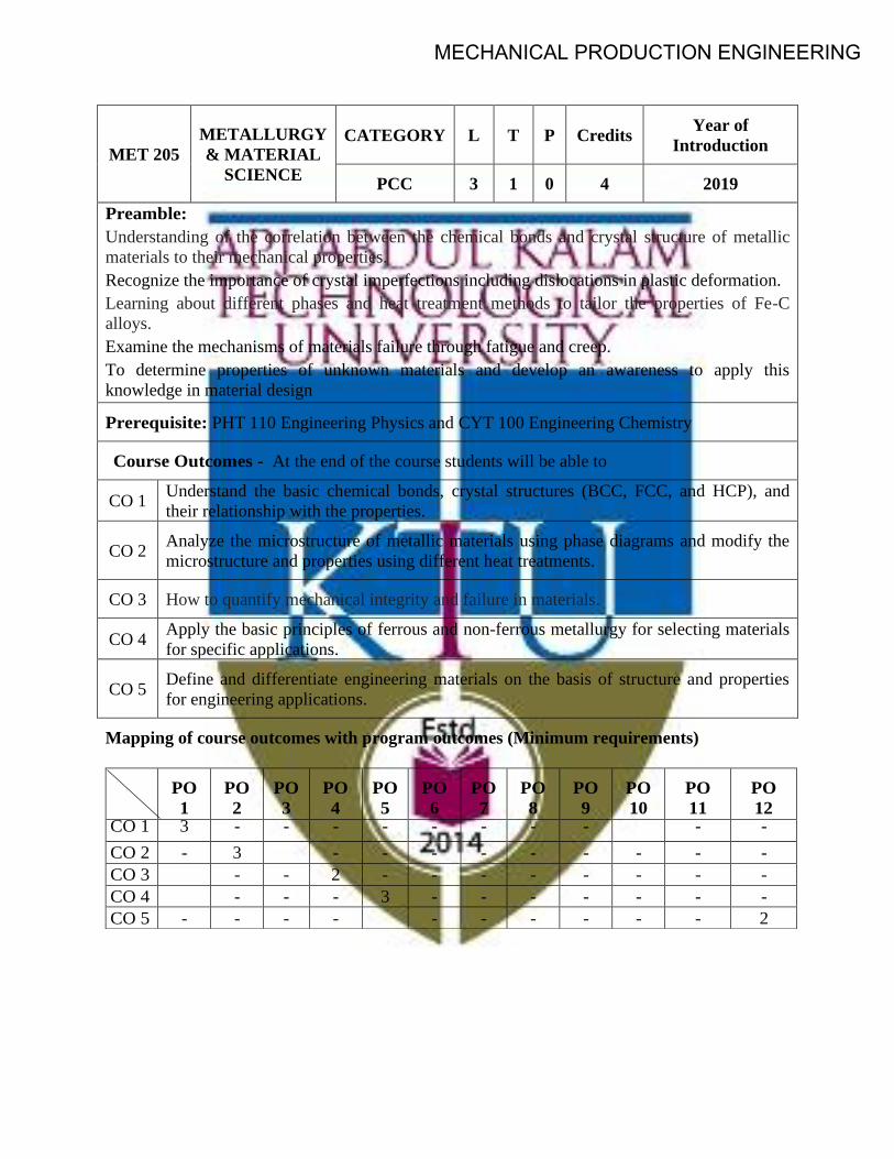
MET 205
METALLURGY
& MATERIAL
SCIENCE
CATEGORY L T P Credits Year of
Introduction
PCC 3 1 0 4 2019
Preamble:
Understanding of the correlation between the chemical bonds and crystal structure of metallic
materials to their mechanical properties.
Recognize the importance of crystal imperfections including dislocations in plastic deformation.
Learning about different phases and heat treatment methods to tailor the properties of Fe-C
alloys.
Examine the mechanisms of materials failure through fatigue and creep.
To determine properties of unknown materials and develop an awareness to apply this
knowledge in material design
Prerequisite: PHT 110 Engineering Physics and CYT 100 Engineering Chemistry
Course Outcomes - At the end of the course students will be able to
CO 1 Understand the basic chemical bonds, crystal structures (BCC, FCC, and HCP), and
their relationship with the properties.
CO 2 Analyze the microstructure of metallic materials using phase diagrams and modify the
microstructure and properties using different heat treatments.
CO 3 How to quantify mechanical integrity and failure in materials.
CO 4 Apply the basic principles of ferrous and non-ferrous metallurgy for selecting materials
for specific applications.
CO 5 Define and differentiate engineering materials on the basis of structure and properties
for engineering applications.
Mapping of course outcomes with program outcomes (Minimum requirements)
PO
1
PO
2
PO
3
PO
4
PO
5
PO
6
PO
7
PO
8
PO
9
PO
10
PO
11
PO
12 CO 1 3 - - - - - - - - - -
CO 2 - 3 - - - - - - - - -
CO 3 - - 2 - - - - - - - -
CO 4 - - - 3 - - - - - - -
CO 5 - - - - - - - - - - 2
MECHANICAL PRODUCTION ENGINEERING

ASSESSMENT PATTERN
Bloom's
taxonomy
Continuous Assessment Tests End Semester Examination
(Marks) Test 1 (Marks) Test 11 (Marks)
Remember 25 25 25
Understand 15 15 15
Apply 30 25 30
Analyze 10 10 10
Evaluate 10 15 10
Create 10 10 10
Mark distribution
Total Marks CIE marks ESE marks ESE duration
150 50 100 3 Hours
Continuous Internal Evaluation (CIE) Pattern:
Attendance 10 marks
Regular class work/tutorials/assignments 15 marks
Continuous Assessment Test (Minimum 2 numbers) 25 marks
End semester pattern:- There will be two parts; Part A and Part B. Part A contain 10
questions with 2 questions from each module, having 3 marks for each question. Students
should answer all questions. Part B contains 2 questions from each module of which student
should answer any one. Each question can have maximum 2 sub-divisions and carry 14
marks.
COURSE LEVEL ASSESSMENT QUESTIONS
Part -A
Course Outcome 1 (CO1): Understand the basic chemical bonds, crystal structures (BCC,
FCC, and HCP), and their relationship with the properties.
1. What are the attributes of atomic and crystalline structures into the stress - strain curve?
2. Explain the significance of long range and short range order of atomic arrangement on
mechanical strength.
3. What is the difference between an allotrope and a polymorphism?
4. Draw the (112) and (111) planes in simple cubic cell.
MECHANICAL PRODUCTION ENGINEERING

Course Outcome 2 (CO2): Analyze the microstructure of metallic materials using phase diagrams
and modify the microstructure and properties using different heat treatments.
1. What is the driving force for recrystallisation and grain growth of metallic crystals?
2. What is the driving force for the formation of spheroidite.
3. What is tempered martensite?
4. Why 100 % pure metals are weak in strength?
Part -B
Course Outcome 3 (CO3): How to quantify mechanical integrity and failure in materials
1. A small hole is drilled through a steel plate ahead of a crack, whether it can stop the crack’s
progress until repairs can be made. Explain in detail and derive the equation for the principle.
2. Draw and explain S-N curves for ferrous and non-ferrous metals. Explain different methods to
improve fatigue resistance.
3. Explain different stages of creep; Give an application of creep phenomenon. What is
superplasticity?
Course Outcome 4 (CO4): Apply the basic principles of ferrous and non-ferrous metallurgy for
selecting materials for specific applications.
1. What are the classification, compositions and applications of high speed steel? identify 18:4:1
2. Describe the composition, properties, and use of Bronze and Gun metal.
3. Explain the importance of all the non-ferrous alloys in automotive applications. Elaborate on
the composition, properties and typical applications of any five non-ferrous alloys.
Course Outcome 5 (CO5): Define and differentiate engineering materials on the basis of structure
and properties for engineering applications.
1. Carbon is allowed to diffuse through a steel plate 15 mm thick. The concentrations of carbon at
the two faces are 0.65 and 0.30kgC/m3Fe, which are maintained constant. If the pre-
exponential and activation energy are 6.2x10⁻⁷m2/s and 80,000 J/mol, respectively, compute
the temperature at which the diffusion flux is 1.43 x 10⁻⁹ kg/m2-s.
2. Explain the fundamental effects of alloying elements in steel on polymorphic transformation
temperatures, grain growth, eutectoid point, retardation of the transformation rates, formation
and stability of carbides.
3. Describe the kind of fracture which may occur as a result of a loose fitting key on a shaft.
SYLLABUS
MODULE - 1
Earlier and present development of atomic structure - Primary bonds: - characteristics of covalent,
ionic and metallic bond - properties based on atomic bonding: - Secondary bonds: - classification,
application. (Brief review only).
Crystallography: - SC, BCC, FCC, HCP structures, APF - theoretical density simple problems - Miller
Indices: - crystal plane and direction - Modes of plastic deformation: - Slip and twinning -Schmid's
law - Crystallization: Effects of grain size, Hall - Petch theory, simple problems.
MECHANICAL PRODUCTION ENGINEERING

MODULE - II
Classification of crystal imperfections - forest of dislocation, role of surface defects on crack
initiation- Burgers vector –Frank Read source - Correlation of dislocation density with strength and
nano concept - high and low angle grain boundaries– driving force for grain growth and applications -
Polishing and etching - X – ray diffraction, simple problems –SEM and TEM - Diffusion in solids,
fick’s laws, mechanisms, applications of diffusion in mechanical engineering, simple problems.
MODULE - III
Phase diagrams: - need of alloying - classification of alloys - Hume Rothery`s rule - equilibrium
diagram of common types of binary systems: five types - Coring - lever rule and Gibb`s phase rule -
Reactions- Detailed discussion on Iron-Carbon equilibrium diagram with microstructure and
properties -Heat treatment: - TTT, CCT diagram, applications - Tempering- Hardenability, Jominy end
quench test, applications- Surface hardening methods.
MODULE - IV
Strengthening mechanisms - cold and hot working - alloy steels: how alloying elements affecting
properties of steel - nickel steels - chromium steels - high speed steels -cast irons - principal non
ferrous alloys.
MODULE - V
Fatigue: - creep -DBTT - super plasticity - need, properties and applications of composites, super
alloy, intermetallics, maraging steel, Titanium - Ceramics:- structures, applications.
Text Books
1. Callister William. D., Material Science and Engineering, John Wiley, 2014
2. Higgins R.A. - Engineering Metallurgy part - I – ELBS,1998
Reference
1. Avner H Sidney, Introduction to Physical Metallurgy, Tata McGraw Hill,2009
2. Anderson J.C. et.al., Material Science for Engineers, Chapman and Hall,1990
3. Clark and Varney, Physical metallurgy for Engineers, Van Nostrand,1964
4. Dieter George E, Mechanical Metallurgy, Tata McGraw Hill, 1976
5. Raghavan V, Material Science and Engineering, Prentice Hall,2004
6. Reed Hill E. Robert, Physical metallurgy principles, 4th edition, Cengage Learning,2009
7. Myers Marc and Krishna Kumar Chawla, Mechanical behavior of materials, Cambridge
University press,2008
8. Van Vlack -Elements of Material Science - Addison Wesley,1989
9. https://nptel.ac.in/courses/113/106/113106032
MECHANICAL PRODUCTION ENGINEERING

MODEL QUESTION PAPER
METALLURGY & MATERIAL SCIENCE - MET 205
Max. Marks : 100 Duration : 3 Hours
Part – A
Answer all questions.
Answer all questions, each question carries 3 marks
1. What is a slip system? Describe the slip systems in FCC, BCC and HCP metals
2. NASA's Parker Solar Probe will be the first-ever mission to "touch" the Sun. The spacecraft,
about the size of a small car, will travel directly into the Sun's atmosphere about 4 million miles
from the earth surface. Postulate the coolant used in the parker solar probe with chemical
bonds.
3. What is the driving force for grain growth during heat treatment
4. What are the roles of surface imperfections on crack initiation
5. Explain the difference between hardness and hardenability.
6. What is tempered martensite? Explain its structure with sketch.
7. Postulate, why cast irons are brittle?
8. How are properties of aluminum affected by the inclusion of (a) copper and (b) silicon as alloying
elements?
9. What is the grain size preferred for creep applications? Why. Explain thermal fatigue?
10. Explain fracture toughness and its attributes into a screw jack?
PART -B
Answer one full question from each module.
MODULE – 1
11. a. Calculate the APF of SC, BCC and FCC (7 marks).
b. What is slip system and explain why FCC materials exhibit ductility and B C C a n d HCP
exhibit brittle nature with details of slip systems (7 marks).
OR
12. Explain the effect of: (i) Grain size; (ii) Grain size distribution and (iii) Grain orientation (iv)
Grain shape on strength and creep resistance with neat sketches. Attributes of Hall-Petch
equation and grain boundaries (14 marks).
MODULE – 2
13. a. Describe step by step procedure for metallographic specimen preparation? Name different
types etchants used for specific metals and methods to determine grain size (7 marks).
MECHANICAL PRODUCTION ENGINEERING

b. Carbon is allowed to diffuse through a steel plate 15 mm thick. The concentrations of carbon
at the two faces are 0.65 and 0.30 kgC/m3Fe, which are maintained constant. If the pre-
exponential and activation energy are 6.2x10⁻⁷m2/s and 80,000 J/mol, respectively, compute the
temperature at which the diffusion flux is 1.43 x 10⁻⁹ kg/m2-s (7 marks).
OR
14. a. Explain the fundamental differences of SEM and TEM with neat sketches (7 marks).
b. A beam of X-rays wavelength 1.54Å is incident on a crystal at a glancing angle of 8o35’
when the first order Bragg’s reflection occurs calculate the glancing angle for third order
reflection (7 marks).
MODULE – 3
15. Postulate with neat sketches, why 100% pure metals are weaker? What are the primary
functions of alloying? Explain the fundamental rules governing the alloying with neat sketches
and how is it accomplished in substitution and interstitial solid solutions (14 marks).
OR
16. Draw the isothermal transformation diagram of eutectoid steel and then sketch and label (1) A
time temperature path that will produce 100% pure coarse and fine pearlite (2) A time
temperature path that will produce 50% martensite and 50% bainite (3) A time temperature
path that will produce 100% martensite (4) A time temperature path that will produce 100%
bainite (14 marks).
MODULE – 4
17. Explain the effect of, polymorphic transformation temperature, formation and stability of
carbides, grain growth, displacement of the eutectoid point, retardation of the transformation
rates, improvement of corrosion resistance on adding alloy elements to steel (14 marks).
OR
18. Give the composition, microstructure, properties and applications of (i) Gray iron and SG iron.
(ii) White iron and Gray iron. (iii) Malleable iron and Gray iron. (iv) Gray iron and Mottled
iron, (v) SG iron and Vermicullar Graphite Iron (14 marks).
MODULE – 5
19. a A small hole is drilled through a steel plate ahead of a crack, whether it can stop the crack’s
progress until repairs can be made or not? Explain in detail and derive the equation
(7 marks).
b What is ductile to brittle transition in steel DBTT? What are the factors affecting ductile to
brittle transition? Narrate with neat sketch (7 marks).
OR
20. Classify ceramics with radius ratio with neat sketches. Explain with an example for each of the
AX, AmXp, AmBmXp type structures in ceramics with neat sketch (14 marks).
MECHANICAL PRODUCTION ENGINEERING

COURSE CONTENT AND LECTURE SCHEDULES.
Module TOPIC
No.
of
hours
Course
outcomes
1.1
Earlier and present development of atomic structure; attributes of ionization
energy and conductivity, electronegativity; correlation of atomic radius to
strength; electron configurations; - Primary bonds: - characteristics of
covalent, ionic and metallic bond: attributes of bond energy, cohesive force,
density, directional and non-directional - properties based on atomic
bonding:- attributes of deeper energy well and shallow energy well to melting
temperature, coefficient of thermal expansion - attributes of modulus of
elasticity in metal cutting process -Secondary bonds:- classification- hydrogen
bond and anomalous behavior of ice float on water, application- specific
heat, applications. (Brief review only).
2 CO1
1.2
Crystallography:- Crystal, space lattice, unit cell- SC, BCC, FCC, atomic
packing factor and HCP structures - short and long range order - effects of
crystalline and amorphous structure on mechanical properties.
2 CO1
CO2
1.3 Coordination number and radius ratio; theoretical density; simple problems -
Polymorphism and allotropy. 1
1.4
Miller Indices: - crystal plane and direction - Attributes of miller indices for
slip system, brittleness of BCC, HCP and ductility of FCC - Modes of plastic
deformation: - Slip and twinning.
1
CO5
1.5 Schmid's law, equation, critical resolved shear stress, correlation of slip
system with plastic deformation in metals and applications. 1
1.6
Mechanism of crystallization: Homogeneous and heterogeneous nuclei
formation, under cooling, dendritic growth, grain boundary irregularity -
Effects of grain size, grain size distribution, grain shape, grain orientation on
dislocation/strength and creep resistance - Hall - Petch theory, simple
problems.
2 CO2
2.1 Classification of crystal imperfections: - types of point and dislocations. 1
CO2 2.2
Effect of point defects on mechanical properties - forest of dislocation, role of
surface defects on crack initiation - Burgers vector. 1
2.3
Dislocation source, significance of Frank-Read source in metals deformation -
Correlation of dislocation density with strength and nano concept,
applications. 3 CO2
2.4 Significance high and low angle grain boundaries on dislocation – driving
force for grain growth and applications during heat treatment.
2.5
Polishing and etching to determine the microstructure and grain size-
Fundamentals and crystal structure determination by X – ray diffraction,
simple problems –SEM and TEM.
2 CO2
CO5
2.6 Diffusion in solids, fick’s laws, mechanisms, applications of diffusion in
mechanical engineering, simple problems. 1
MECHANICAL PRODUCTION ENGINEERING

3.1
Phase diagrams: - Limitations of pure metals and need of alloying -
classification of alloys, solid solutions, Hume Rothery`s rule - equilibrium
diagram of common types of binary systems: five types.
2 CO2
CO5
3.2 Coring - lever rule and Gibb`s phase rule - Reactions: - monotectic, eutectic,
eutectoid, peritectic, peritectoid. 1
3.3
Detailed discussion on Iron-Carbon equilibrium diagram with microstructure
and properties changes in austenite, ledeburite, ferrite, cementite, special
features of martensite transformation, bainite, spheroidite etc. 3
CO2
CO5
3.4
Heat treatment: - Definition and necessity – TTT for a eutectoid iron–carbon
alloy, CCT diagram, applications - annealing, normalizing, hardening,
spheroidizing.
3.5
Tempering:- austermpering, martempering and ausforming - Comparative
study on ductility and strength with structure of pearlite, bainite, spherodite,
martensite, tempered martensite and ausforming.
1 CO2
3.6
Hardenability, Jominy end quench test, applications- Surface hardening
methods:- no change in surface composition methods :- Flame, induction, laser
and electron beam hardening processes- change in surface composition
methods :carburizing and Nitriding; applications.
2
CO2
4.1
Cold working: Detailed discussion on strain hardening; recovery; re-
crystallization, effect of stored energy; re- crystallization temperature -
hot working, Bauschinger effect and attributes in metal forming.
1
4.2
Alloy steels:- Effects of alloying elements on steel: dislocation movement,
polymorphic transformation temperature, alpha and beta stabilizers, formation
and stability of carbides, grain growth, displacement of the eutectoid point,
retardation of the transformation rates, improvement in corrosion resistance,
mechanical properties
1 CO4
4.3
Nickel steels, Chromium steels etc. – change of steel properties by adding
alloying elements: - Molybdenum, Nickel, Chromium, Vanadium, Tungsten,
Cobalt, Silicon, Copper and Lead - High speed steels - Cast irons:
Classifications; grey, white, malleable and spheroidal graphite cast iron etc,
composition, microstructure, properties and applications - Principal Non
ferrous Alloys: - Aluminum, Copper, Magnesium, Nickel, study of
composition, properties, applications, reference shall be made to the phase
diagrams whenever necessary.( Topic 4.3 may be considered as a assignment).
4 CO4
CO5
4.4 Fatigue: - Stress cycles – Primary and secondary stress raisers - Characteristics
of fatigue failure, fatigue tests, S-N curve. 1
CO3
4.5
Factors affecting fatigue strength: stress concentration, size effect, surface
roughness, change in surface properties, surface residual stress - Ways to
improve fatigue life – effect of temperature on fatigue, thermal fatigue and its
applications in metal cutting.
2
MECHANICAL PRODUCTION ENGINEERING

5.1
Fracture: – Brittle and ductile fracture – Griffith theory of brittle fracture –
Stress concentration, stress raiser – Effect of plastic deformation on crack
propagation - transgranular, intergranular fracture - Effect of impact loading on
ductile material and its application in forging, applications - Mechanism of
fatigue failure.
2
CO3
5.2
Structural features of fatigue: - crack initiation, growth, propagation - Fracture
toughness (definition only), applications - Ductile to brittle transition
temperature (DBTT) in steels and structural changes during DBTT,
applications.
1
5.3
Creep: - Creep curves – creep tests - Structural change:- deformation by slip,
sub-grain formation, grain boundary sliding - Mechanism of creep deformation
- threshold for creep, prevention against creep - Super plasticity: need and
applications
2 CO3
5.4 Composites: - Need of development of composites; fiber phase; matrix phase;
only need and characteristics of PMC, MMC, and CMC. 2
CO3
CO5 5.5
Modern engineering materials: - only fundamentals, need, properties and
applications of, intermetallics, maraging steel, super alloys, Titanium-
Ceramics:-coordination number and radius ratios- AX, AmXp, AmBmXp type
structures – applications.
3
MECHANICAL PRODUCTION ENGINEERING

MPL 201
PRODUCTION ENGINEERING
DRAWING
CATEGORY L T P CREDIT YEAR OF INTRODUCTION
PCC 0 0 3 2 2019
Preamble:
To introduce students to the basics and standards of engineering drawing related to machines and components.
To familiarize students with different types of riveted, welded, surface roughness symbols; limits, fits and tolerances.
To make students understand the principles and requirements of machine and production drawings.
To learn how to assemble and disassemble important valves, machine components used in mechanical engineering applications.
To gain knowledge about standard CAD packages on modeling and drafting
Prerequisite:
EST 110 - Engineering Graphics
Course Outcomes:After the completion of the course the student will be able to
CO 1 Understand and apply the knowledge of machine drawing as a system of communication in which ideas are expressed clearly and all information fully conveyed
CO 2 Interpret the welded, machining and surface roughness symbols on the component drawings.
CO 3 Apply limits and tolerances to assemblies and choose appropriate fits for given assemblies
CO 4 Preparation of engineering and working drawings with dimensions and bill of material during design and development. Developing assembly drawings using part drawings of machine/valve components.
CO 5 Assemble and model components using CAD software
Mapping of course outcomes with program outcomes
PO 1 PO 2 PO 3 PO 4 PO 5 PO 6 PO 7 PO 8 PO 9 PO 10
PO 11
PO 12
CO 1 3 CO 2 3 CO 3 3 CO 4 2 CO 5 3 3
MECHANICAL PRODUCTION ENGINEERING

Assessment Pattern
Bloom’s Category Continuous Assessment Tests
End Semester Examination
1(Manual) 2 (CAD) Remember 20 20 10 Understand 40 20 30 Apply 40 40 40 Analyse 20 20 Evaluate Create
Mark distribution
Total Marks
CIE ESE ESE Duration
150 75 75 2.5 hours
Continuous Internal Evaluation Pattern:
Attendance : 15 marks Continuous Assessment Test (minimum 2 tests) : 30 marks Regular class work/Drawing/Lab Record and Class Performance : 30 marks The first internal test (manual examination) will be based on Modules I and II and the second internal exam will be based on Module III and IV(CAD Examination). End Semester Examination Pattern: Examination duration: 2.5 hours Maximum Marks: 75 The following guidelines should be followed regarding award of marks CAD Drawing Exercise (Questions shall be based on Module IV and V) : 60 Marks Viva Voce (Questions shall be based on all modules) : 15 Marks Conduct of University Practical Examinations: The Principals of the concerned Engineering Colleges with the help of the Chairmen/Chairperson will conduct the practical examination with the approval from the University and bonafide work / laboratory record, hall ticket, identity card issued by college are mandatory for appearing practical University examinations. No practical examination should be conducted without the presence of an external examiner appointed by the University.
MECHANICAL PRODUCTION ENGINEERING

Model Question Paper End Semester Examination
MPL201 Production Engineering Drawing Part A(60marks)
(Answer any one question)
1. Draw (a) half sectional view from the front, top half in section and (b) view from the side of a protected flange coupling to connect two shafts and prepare the bill of materials and tolerance data sheet in any modelling software.
MECHANICAL PRODUCTION ENGINEERING

2. A screw jack has the part details as shown in Fig-3. Prepare the following assembled views. i) Elevation left half in section, ii) Plan and prepare the bill of materials and tolerance data sheet in any modelling software.
MECHANICAL PRODUCTION ENGINEERING

Syllabus
Module 1
Conventions in Machine Drawing, Dimensioning technique for machine components, Conventionalrepresentation of machine components as per IS code: SP-46 such as screw threads, tapped holes, knurling parts, splined shafts, tapers, chamfers, countersunk and counter bores and keys.
Surface Roughness.Introduction, terminology, machining symbols with all parameters, roughness values (Ra) and roughness grade numbers,indicating surface roughness on drawing.
Module 2
Limits Fits and Tolerances Definitions, types of tolerance, Systems of dimensional tolerances and fits, types of fits, fit system. Geometrical tolerances – Nomenclature, tolerance frame, types of geometrical tolerances & their symbols, indicating geometric tolerances on drawing, calculation of fundamental deviations and tolerances
Module 3
Joints: Threaded Fasteners :Thread terminology, thread forms, thread designations, single and multi-start threads, right and left hand threads, types of screws , bolts and nuts, nut locking arrangements using pins, washers & screws. Riveted joints: types of riveted joints, symbolic representation Foundation bolts
Module 4
Using CAD: Introduction to part and assembly drawing. Exercise on preparation of sectional drawings of cotter joint, knuckle joint, flange joint and flexible coupling- Preparation of bill of materials.
Module 5
Exercise on preparation of assembly drawings of revolving centers, plummer block, connecting rod, machine vice, screw jack and lathe tailstock using CAD- Preparation of bill of materials and tolerance data sheet.
Reference Books
1. Narayana K. L., Kannaiah P., VenkatataReaddy K., “Machine Drawing”, 2ndEdition, New age international Publishers, Delhi, 2008, ISBN 81-224-1917-8. 2. Bhat N. D., Panchal , “Machine Drawing”, Charotar Pub. House, 2000.ISBN: 9380358466. 3. Gill P. S., “A Text book of Machine Drawing”, Revised Edition K. Kataria and Sons, New Delhi, 2008, ISBN: 81-85749-79-5. 4. PI Varghese & K C John7. R K Bansal, “Hydraulic Machines”
MECHANICAL PRODUCTION ENGINEERING

Course Contents and Practical Schedule No Topic No. of Hours
1 Module I
1.1 Conventions in Machine Drawing, Dimensioning technique for machine components, Conventional representation of machine components as per IS code: SP-46 such as screw threads, tapped holes, knurling parts, splined shafts, tapers, chamfers, countersunk and counter bores and keys.
3
1.2 Surface Roughness. Introduction, terminology, machining symbols with all parameters, roughness values (Ra) and roughness grade numbers, indicating surface roughness on drawing.
3
2 Module II 2.1 Limits Fits and Tolerances Definitions, types of tolerance, Systems of
dimensional tolerances and fits, types of fits, fit system. Geometrical tolerances – Nomenclature, tolerance frame, types of geometrical tolerances & their symbols, indicating geometric tolerances on drawing, calculation of fundamental deviations and tolerances
3
3 Module III 3.1 Joints: Threaded Fasteners :Thread terminology, thread forms,
thread designations, single and multi-start threads, right and left hand threads, types of screws , bolts and nuts, nut locking arrangements using pins, washers & screws.
3
3.2 Riveted joints: types of riveted joints, symbolic representation Foundation bolts
3
4 Module IV 4.1 Using CAD: Introduction to part and assembly drawing. Exercise on
preparation of sectional drawings of cotter joint, knuckle joint, flange joint and flexible coupling- Preparation of bill of materials.
6
5 Module V 5.1 Exercise on preparation of assembly drawings of revolving centers,
plummer block, connecting rod, machine vice, screw jack and lathe tailstock using CAD- Preparation of bill of materials and tolerance data sheet.
9
MECHANICAL PRODUCTION ENGINEERING

CODE MEL203
COURSE NAME MATERIALS TESTING LAB
CATEGORY L T P CREDIT PCC 0 0 3 2
Preamble:
The objective of this course is to give a broad understanding of common materials related to mechanical engineering with an emphasis on the fundamentals of structure-property-application and its relationships. A group of 6/7 students can conduct experiment effectively. A total of six experiments for the duration of 2 hours each is proposed for this course.
Prerequisite: A course on Engineering Mechanics is required
Course Outcomes:
After the completion of the course the student will be able to
CO 1 To understand the basic concepts of analysis of circular shafts subjected to torsion. CO 2 To understand the behaviour of engineering component subjected to cyclic loading and
failure concepts CO 3 Evaluate the strength of ductile and brittle materials subjected to compressive, Tensile
shear and bending forces CO 4 Evaluate the microstructural morphology of ductile or brittle materials and its fracture
modes (ductile /brittle fracture) during tension test CO 5 To specify suitable material for applications in the field of design and manufacturing.
Mapping of course outcomes with program outcomes
PO 1 PO 2 PO 3 PO 4 PO 5 PO 6 PO 7 PO 8 PO 9 PO 10 PO 11 PO 12
CO 1 3 3 CO 2 3 3 1 3 3 2 2 1 CO 3 3 3 3 1 3 3 2 3 2 CO 4 3 3 3 3 3 2 2 1 3 2 3 2 CO 5 3 3 3 1 3 2 2 1 3 2 3 2
Assessment Pattern
Mark distribution
Total Marks CIE ESE ESE Duration
150 75 75 2.5 hours
MECHANICAL PRODUCTION ENGINEERING

Continuous Internal Evaluation Pattern:
Attendance : 15 marks Continuous Assessment : 30 marks Internal Test (Immediately before the second series test) : 30 marks
End Semester Examination Pattern:
The following guidelines should be followed regarding award of marks (a) Preliminary work : 15 Marks (b) Implementing the work/Conducting the experiment : 10 Marks (c) Performance, result and inference (usage of equipments and troubleshooting) : 25 Marks (d) Viva voce : 20 marks (e) Record : 5 Marks
General instructions:
Practical examination to be conducted immediately after the second series test covering entire syllabus given below. Evaluation is a serious process that is to be conducted under the equal responsibility of both the internal and external examiners. The number of candidates evaluated per day should not exceed 20. Students shall be allowed for the University examination only on submitting the duly certified record. The external examiner shall endorse the record.
A minimum of 10 experiments are to be performed.
SYLLABUS
LIST OF EXPERIMENTS
1. To conduct tension test on ductile material (mild steel/ tor-steel/ high strength steel) usingUniversal tension testing machine and Extensometer.
2. To conduct compression test on ductile material (mild steel/ tor-steel/ high strength steel)using Universal tension testing machine and Extensometer.
3. To conduct tension test on Brittle material (cast iron) using Universal tension testingmachine and Extensometer.
4. To conduct shear test on mild steel rod.
5. To conduct microstructure features of mild steel/copper/ brass/aluminium using opticalmicroscope, double disc polishing machine, emery papers and etchent.
6. To conduct fractography study of ductile or brittle material using optical microscope.
MECHANICAL PRODUCTION ENGINEERING

7. To conduct Hardness test of a given material. (Brinell, Vickers and Rockwell)
8. To determine torsional rigidity of mild steel/copper/brass rod.
9. To determine flexural rigidity of mild steel/ copper/brass material using universal testingmachine.
10. To determine fracture toughness of the given material using Universal tension testingmachine.
11. To study the procedure for plotting S-N curve using Fatigue testing machine.
12. To conduct a Toughness test of the given material using Izod and Charpy Machine.
13. To determine spring stiffness of close coiled/open coiled/series/parallel arrangements.
14. To conduct bending test on wooden beam.
15. To conduct stress measurements using Photo elastic methods.
16. To conduct strain measurements using strain gauges.
17. To determine moment of inertia of rotating bodies.
18. To conduct an experiment to Verify Clerk Maxwell’s law of reciprocal deflection anddetermine young's Modulus of steel.
19. To determine the surface roughness of a polished specimen using surface profilometer.
Reference Books
1. G E Dieter. Mechanical Metallurgy, McGraw Hill,2013
2. Dally J W, Railey W P, Experimental Stress analysis , McGarw Hill,1991
3. Baldev Raj, Jayakumar T, Thavasimuthu M., Practical Non destructive testing, Narosa Book
Distributors,2015
MECHANICAL PRODUCTION ENGINEERING

SEMESTER -3
MINOR
MECHANICAL PRODUCTION ENGINEERING
Preamble:
Inspection is required during production for quality control because of the inherent variability introduced by the machines, tools, raw materials, and human operators which causes variations in the different quality characteristics of the product. Non-destructive inspection methods help to perform in-service inspection to avoid any failure and to ensure the quality of the product.
Prerequisite:
Nil
Course Outcomes:After the completion of the course the student will be able to
CO 1 Understand the basic concepts of different types of inspection techniques CO 2 Analyse the results of industrial radiographic test. CO 3 Explain the working principle of Ultrasonic Testing and use it for industrial needs CO 4 Explain the working of Eddy Current and Electro Magnetic Testing CO 5 Analyse and distinguish the different NDT methods and recommend the suitable one
for industrial application.
Mapping of course outcomes with program outcomes
PO 1 PO 2 PO 3 PO 4 PO 5 PO 6 PO 7 PO 8 PO 9 PO 10
PO 11
PO 12
CO 1 3 CO 2 3 2 CO 3 3 CO 4 3 CO 5 2 CO 6 3 2
Assessment Pattern
Bloom’s Category Continuous Assessment Tests
End Semester Examination
1 2 Remember 20 20 20 Understand 10 10 10 Apply 30 30 40 Analyse 20 20 20 Evaluate 10 10 10 Create 10 10
MPT281 INDUSTRIAL INSPECTION
METHODS
CATEGORY L T P CREDIT YEAR OF INTRODUCTION
VAC 3 1 0 4 2019
MECHANICAL PRODUCTION ENGINEERING

Mark distribution
Total Marks
CIE ESE ESE Duration
150 50 100 3 hours
Continuous Internal Evaluation Pattern:
Attendance : 10 marks Continuous Assessment Test (2 numbers) : 25 marks Assignment/Quiz/Course project : 15 marks End Semester Examination Pattern: There will be two parts; Part A and Part B. Part A contain 10 questions with 2 questions from each module, having 3 marks for each question. Students should answer all questions. Part B contains 2 questions from each module of which student should answer any one. Each question can have maximum 2 sub-divisions and carry 14 marks.
Course Level Assessment Questions
Course Outcome 1 (CO1):
Explain the importance of inspection in manufacturing sector.
Course Outcome 2 (CO2)
Explain about various steps involved in film processing in RT.
Course Outcome 3(CO3):
Explain about the working of ultrasonic transducer. Include necessary figures.
Course Outcome 4 (CO4):
Discuss the advantages and limitations of magnetic methods.
Course Outcome 5 (CO5):
Identify the best non –destructive method for inspection of boilers.
MECHANICAL PRODUCTION ENGINEERING

Model Question Paper
Part A
1. What are the properties required for a good penetrant?
2.Differentiate between destructive and non-destructive testing techniques
3. List the properties of gamma rays and X rays.
4. List the safety measures to be carried out during radiography testing.
5.What is sensitivity in MPI?
6. List the advantages and disadvantages of Ultrasonic testing
7. Write short notes about the standard depth of penetration in ECT
8. List the various applications of ECT.
9.Explain the wave mode in Acoustic emission testing.
10. Discuss how measuring instruments are classified
(10*3 Marks=30 Marks)
Part B
11.a)Explain visual inspection process. Also explain about the different types of optical
aids used in the process. (7 Marks)
b) What are the different visual aids used in Visual Inspection? Explain any two in detail.
(7 marks)
OR
12.a) With neat sketches explain the different steps in liquid penetrant testing.(10 marks)
b) Explain about advantages and disadvantages of liquid penetrant testing. (4 mark)
13.a)Explain SWSI,DWSI and DWDI inspection techniques in radiographic testing.(10 marks)
b) How the quality of good radiograph is accessed? (4 marks)
OR
MECHANICAL PRODUCTION ENGINEERING

14.a) Explain about various steps involved in film processing in RT. (7 marks)
b) Write short notes about various safety aspects required in RT. (7 marks)
15.a) With the help of neat figures, differentiate between through transmission technique and pulse echo testing techniques used in ultrasonic testing. (10 marks)
b) Explain about the working of ultrasonic transducer. Include necessary figures. (4 marks)
OR
16.a) An 8 mm thick MS plate of size 300 mm X 250 mm has to be tested for internal defects. Explain the inspection procedure with sketches using magnetic prod. (7 marks)
b) With the help of neat sketches explain about any four types of magnetisation techniques used in magnetic particle inspection (MPI). (7 marks)
17.a) Explain about eddy current testing (ECT) technique in detail. List the advantages and disadvantages of the process. Include necessary figures.(10 marks).
b) Explain the following terms associated with ECT: i) Lift off effect ii) Edge effect (4 marks)
OR
18.a) Explain constant current drive and scanning probe ECT techniques. (8 marks)
b) Explain the advantages and limitations of eddy current testing. (6 marks)
19.a) Explain the principle of acoustic emission (6 Marks)
b) Discuss the advantages and disadvantages of Acoustic Emission techniques.(8 Marks)
OR
20.a) Discuss any two linear measurement devices. (10)
b) ) Define the following terms used in screw thread:- (i) Pitch (ii) Lead (iii) Major Diameter (iv) Minor Diameter
MECHANICAL PRODUCTION ENGINEERING

Syllabus
Module 1
Introduction, Fundamental Concept of Quality, Need of Inspection, Inspection types and Principles, Destructive Inspection, Testing of Composite Materials
Introduction: Visual methods: Optical aids, In-situ metallography, Optical holographic methods, Dynamic inspection. Penetrant flaw detection: Principles, Process. Penetrant systems: Liquid Penetrant materials: Emulsifiers, cleaners, developers, sensitivity, Process, Advantages, Limitations, Applications.
Module 2
Radiographic methods and Limitations: Principles of radiography: sources of radiation, Ionising radiation - X-rays sources, generation and properties. Gamma-ray sources Recording of radiation: Radiographic sensitivity, Fluoroscopic methods, special techniques, Radiation safety. Principle and application of in-motion and flash radiography. Inspection techniques like SWSI, DWSI, DWDI, panoramic exposure, real time radiography, films used in industrial radiography, types of film, speed of films, qualities of film
Module 3
Ultrasonic testing of materials: Advantages, disadvantages, Applications. Generation of Ultrasonic waves, general characteristics of ultrasonic waves: methods and instruments for ultrasonic materials testing: special techniques.
Magnetic methods: Advantages, Limitations, Methods of generating fields: magnetic particles and suspending liquids Magnetography, field sensitive probes: applications. Measurement of metal properties.
Module 4
Electrical methods: Eddy current methods: potential-drop methods, applications. Electromagnetic testing: Magnetism: Magnetic domains: Magnetization curves: Magnetic Hysteresis: Hysteresis-loop tests: comparator - bridge tests Absolute single-coil system: applications.
Module 5
Acoustic Emission methods, Acoustic methods: Leak detection: Thermal inspection: Advantages and Disadvantages
Engineering Metrology: Linear Measurement, Angular Measurement, Measurement of Surface Finish, Screw Thread Metrology.
MECHANICAL PRODUCTION ENGINEERING

Text Books
1. Raj B., T. Jayakumar and M Thavasimuthu, Non-Destructive Testing, Narosa Publishing House, 2002.
Reference Books
1. Hull B. and V.John, Non-Destructive Testing, Macmillan,1988
2. Krautkramer, Josef and Hebert Krautkramer, Ultrasonic Testing of Materials, SpringerVerlag,
1990
3. Halmshaw R., Introduction to the Non-Destructive Testing of Welded Joints, 1997.
4. Metals Handbook – Non-destructive Inspection and Quality Control (V. II), ASM, 1976.
5. McGonagle W. J., Non-Destructive Testing, McGraw Hill, 1961.
MECHANICAL PRODUCTION ENGINEERING

Course Contents and Lecture Schedule No Topic No. of Lectures 1 Module I
1.1 Introduction, Fundamental Concept of Quality, Need of Inspection, 1
1.2 Inspection types and Principles, Destructive Inspection, Testing of Composite Materials
1
1.3 Introduction: Visual methods: Optical aids, In-situ metallography, Optical holographic methods, Dynamic inspection
2
1.4 Penetrant flaw detection: Principles, Process. Penetrant systems: 1 1.5 Liquid Penetrant materials: Emulsifiers, cleaners, developers,
sensitivity, Process, Advantages, Limitations, Applications 2
2 Module II 2.1 Radiographic methods 1 2.2 Principles of radiography: sources of radiation 1 2.3 Ionising radiation - X-rays sources, generation and properties 1 2.4 Gamma-ray sources. Recording of radiation 1 2.5 determination of voltage regulation – EMF method 1 2.6 Radiographic sensitivity, Fluoroscopic methods, 1 2.7 Special techniques, Radiation safety 1 2.8 Principle and application of in-motion and flash radiography 1 2.9 Inspection techniques like SWSI, DWSI, 1 2.10 DWDI, panoramic exposure 1 2.11 Real time radiography, films used in industrial radiography, 1 2.12 Types of film, speed of films, qualities of film 1 3 Module III 3.1 Ultrasonic testing of materials – Applications, Advantages and
Disadvantages 1
3.2 Generation of Ultrasonic waves, general characteristics of ultrasonic waves
1
3.3 methods and instruments for ultrasonic testing, special techniques 1 3.4 Magnetic methods: Advantages, Limitations, 1 3.5 Methods of generating fields: 1 3.6 magnetic particles and suspending liquids 1 3,7 Magnetography, field sensitive probes: applications. 1 3.8 Measurement of metal properties. 1
4 Module IV 4.1 Electrical methods: Eddy current methods 1 4.2 potential-drop methods, applications 1 4.3 Electromagnetic testing: Magnetism 1 4.4 Magnetic domains: Magnetization curves 1 4.5 Magnetic Hysteresis 1
MECHANICAL PRODUCTION ENGINEERING

4.6 Hysteresis-loop tests - comparator - bridge tests 1 4.7 Absolute single-coil system - applications 1 5 Module V 5.1 Acoustic Emission methods, Acoustic methods: 1 5.2 Leak detection: Thermal inspection: Advantages and Disadvantages 1 5.3 Engineering Metrology - Linear Measurement 1 5.4 Angular Measurement 2 5.5 Measurement of Surface Finish 2 5.6 Screw Thread Metrology 1
MECHANICAL PRODUCTION ENGINEERING

SEMESTER -4
MECHANICAL PRODUCTION ENGINEERING
MPT 202
MECHANICAL TECHNOLOGY CATEGORY L T P CREDIT PCC 3 1 0 4
Preamble:
The fundamental concepts of heat transfer, power generation systems, IC Engines and its performance characteristics, Psychrometry, Refrigeration and Air Conditioning, Prerequisite: Nil
Course Outcomes:After the completion of the course the student will be able to
CO 1 Understand the application of basic concepts of heat transfer CO 2 Formulate and solve basic heat transfer problems in engineering CO 3 Understand working principles and performance evaluation of I C engines and
gas turbines
CO 4 Know the principles and working of refrigerators and air conditioning equipment
Mapping of course outcomes with program outcomes
PO 1 PO 2 PO 3 PO 4 PO 5 PO 6 PO 7 PO 8 PO 9 PO 10
PO 11
PO 12
CO 1 3 3 CO 2 3 3 2 2 CO 3 3 3 CO 4 3 3
Assessment Pattern
Bloom’s Category Continuous Assessment Tests
End Semester Examination
1 2 Remember 20 20 20 Understand 10 10 10 Apply 30 30 40 Analyse 20 20 20 Evaluate 10 10 10 Create 10 10
MECHANICAL PRODUCTION ENGINEERING

Mark distribution
Total Marks
CIE ESE ESE Duration
150 50 100 3 hours
Continuous Internal Evaluation Pattern:
Attendance : 10 marks Continuous Assessment Test (2 numbers) : 25 marks Assignment/Quiz/Course project : 15 marks End Semester Examination Pattern: There will be two parts; Part A and Part B. Part A contain 10 questions with 2 questions from each module, having 3 marks for each question. Students should answer all questions. Part B contains 2 questions from each module of which student should answer any one. Each question can have maximum 2 sub-divisions and carry 14 marks.
Course Level Assessment Questions
Course Outcome 1 (CO1):
Understand the application of basic concepts of heat transfer
Course Outcome 2 (CO2)
Formulate and solve basic heat transfer problems in engineering
Course Outcome 3(CO3):
Understand working principles and performance evaluation of I C engines
Course Outcome 4 (CO4):
Know the principles and working of refrigerators and air conditioning equipment
MECHANICAL PRODUCTION ENGINEERING

Syllabus
Module 1
Heat transfer - Field of application- Modes of heat transfer- Conduction- Fourier law of heat conduction, heat flux and thermal conductivity-Factors affecting conductivity- General Heat Conduction Equation in Cartesian Coordinate- thermal diffusivity, One-dimensional steady state conduction through plane walls, hollow cylinders, hollow spheres and their composites with constant conductivity- thermal resistance and equivalent thermal resistance.
Module 2
Convection - classification-Newton law of cooling, heat transfer coefficient, laminar and turbulent flow. Dimensionless numbers and its significance. Buckingham’s Pi theorem and its application to Natural and forced convection heat transfer. Combined conduction and convection-overall heat transfer coefficient, Heat exchangers - Classifications- temperatures variation in Parallel flow, counter flow HE- Analysis of Heat Exchangers –Derivation of LMTD, NTU and effectiveness method(concepts only no derivation required).
Radiation heat transfer - Basic theory of radiation-Spectrum of electromagnetic radiation, Reflection, Absorption and Transmission of radiation - absorptivity, reflectivity and transmissivity-Monochromatic radiation-Laws of radiations- Stefan Boltzman law, Planck’s law, Kirchoff’s law and Wien’s displacement law, Total emissive power-. Black body, Grey body and emissivity .Simple problems.
Module 3
IC Engines – Classification - two-stroke and four stroke engines(Working), theoretical and actual working cycles– SI and CI engines – mean effective pressure– Brake power, Indicated power, efficiencies. Performance test- Morse test – Retardation test – Heat balance test. Combustion phenomena in SI and CI engines- detonation, knocking and alternate fuels.
Module 4
Gas turbine – open and closed cycles – thermodynamics cycles – regeneration – reheating – intercooling – efficiency and performance of gas turbines.Simple problems. Compressors - Classifications- reciprocating compressor-p-v diagram. Rotary compressors- Roots blowers and vane compressors (concepts only)
Module 5
Principles of refrigeration-unit of refrigeration - capacity - Coefficient of Performance – reversed Carnot cycle , Vapour compression system-thermodynamic analysis on T-S diagram and p-h diagram-refrigerants - thermodynamic, physical and chemical properties of refrigerants - selection criteria of refrigerants , ecofriendly refrigerants.
MECHANICAL PRODUCTION ENGINEERING

Vapour Absorption refrigeration – Layout of Ammonia –water system and Electrolux system. Air conditioning – Psychrometry - basic definitions, psychometric chart, psychometric processes - human comfort - comfort chart and limitations (brief discussion only) Summer and Winter Air conditioning, Window type Air conditioning system
Reference Books
1. Rajput R K, Heat and Mass Transfer, S. Chand publishing. 2015. 2. Eastop T. D. and A. McConkay, Applied Thermodynamics , Pearson Education, 5th Ed 3. Thermal Engineering, Ballaney P. L., Khanna publishers, 1994. , 4. Arora C. P., Refrigeration and Air conditioning, Tata McGraw Hill, 2000 5. Sachdeva R. C., Fundamentals of Engineering Heat and Mass Transfer, New Age Science Ltd., 2009. 6. Rajput R. K., Thermal Engineering, Laxmi Publications, 2010
MECHANICAL PRODUCTION ENGINEERING

MODEL QUESTION PAPER
Course Code: MPT202
Course Name: MECHANICAL TECHNOLOGY (MP)
Max. Marks: 100 Duration: 3 Hours
PART A
Answer any ALL questions. Each question carries 3 marks.
Use of Approved Data book is permitted
1 Explain the factors affecting thermal conductivity of a material.
2 Can you practically construct a situation where Fourier Law of heat
conduction is applied to find out amount of heat dissipated? What will be
the different assumptions associated?
3 Explain the terms (i) LMTD and NTU (ii) Effectiveness of a heat exchanger
(iii) Capacity ratio.
4 Illustrate the physical significance of Reynolds number, Prandtle number
and Nusselt number
5. Explain Brake power and indicated power of an IC engine.
6 How IC engines are classified?
7. Compare a gas turbine and an IC engine.
8. Enumerate the applications of compressed air.
9. Define the following terms (i) Tonne of refrigeration (ii) Refrigerating effect
(iii) COP
10 Explain sensible cooling and dehumidification processes.
Total 10x3 =30 Marks
PART B
Answer any TWO questions from each module. Each question carries 14 Marks
MODULE 1
11 Derive the general heat conduction equation in Cartesian coordinate
system
OR
(14)
12. The temperature at the inner and outer surfaces of a boiler wall made of 20
mm thick steel and covered with a insulating material of 5mm thickness are
(14)
MECHANICAL PRODUCTION ENGINEERING

300°C and 50°C respectively. If the thermal conductivities of steel and
insulating material are 58 W/mK and 0.116 W/mK respectively, Determine
the rate of heat flow through the boiler wall and the interface temperature.
MODULE 2
13. Investigate the amount of heat generated in the body of a man if for
comfortable living, the body is to be at 35oC while the environmental
conditions are 15oC. The body of the man may be idealized as a cylinder of
30cm diameter and 160cm height. Use the correlation 𝑁𝑢 = 0.12(𝐺𝑟𝑃𝑟) /
OR
(14)
14. a) Explain the following laws (i) Kirchoffs law of radiation (ii) Wiens
displacement law (iii) Planks law
(4)
b) Derive an expression for logarithmic mean temperature difference in case
of parallel and counter flow heat exchangers.
(10)
MODULE 3
15 a) With neat sketches, explain the working of a four stroke Petrol engine and
show various processes in actual and theoretical PV diagram.
(8)
b) Explain various methods for finding indicated power of CI engines
OR
(6)
16 The following observations were made during a test on two stroke cycle oil
engine running at 350 rpm having bore 20cm and stroke 25 cm.
Brake drum diameter : 1.2 m, Net load on brake drum 400 N, MEP: 2.8 bar,
Fuel consumption is 3.6 kg/hr , the rate of flow water through the cooling
jacket is 455 kJ/hr and Calorific value of fuel is 42000 kJ/kg . Jacket water
temperature is 48oC, Room temperature is 20oC. Heat carried away by the
exhaust gases is 800 kJ/min.
Determine:
(a) (a)Indicated power (b) Brake power (c) Mechanical efficiency (d) Heat
balance sheet for one minute basis
(14)
MODULE 4
17 a) “The efficiency of gas turbine increases with increase in pressure ratio”.
Prove the statement with the help of Brayton cycle.
(6)
b) Explain any three methods for improvement of efficiency of open cycle gas
turbine.
OR
(8)
MECHANICAL PRODUCTION ENGINEERING

18 a) Explain the working of a closed cycle gas turbine with Pv and Ts diagrams. (6)
b) Explain the working of Roots blower and vane compressors with neat sketch (8)
MODULE 5
19 a) Define Psychrometry. Explain the following terms (i) Humidity ratio (ii)
Dry bulb temperature (iii) Relative humidity (iv) Sensible cooling
(6)
b) Explain the working of vapour absorption cooling system with neat sketch.
OR
(8)
20. a) List desirable properties of an ideal refrigerant. (4)
b) Explain the working of a vapour compression refrigeration system. Show
various thermodynamic processes in T s and Ph diagrams.
(10
MECHANICAL PRODUCTION ENGINEERING

Course Contents and Lecture Schedule No Topic No. of Lectures
1 Module I
1.1 Heat transfer - Field of application- Modes of heat transfer- Conduction-
1
1.2 Fourier law of heat conduction, heat flux and thermal conductivity-Factors affecting conductivity
1
1.3 General Heat Conduction Equation in Cartesian Coordinate- thermal diffusivity,
1
1.4 One-dimensional steady state conduction through plane walls, 1
1.5 hollow cylinders 1
1.6 hollow spheres and their composites with constant conductivity
1
1.7 thermal resistance and equivalent thermal resistance. 1
2 Module II 2.1 Convection - classification-Newton law of cooling, heat
transfer coefficient, laminar and turbulent flow. 1
2.2 Dimensionless numbers and its significance. Buckingham’s Pi theorem and its application to Natural and forced convection heat transfer.
1
2.3 Combined conduction and convection-overall heat transfer coefficient,
1
2.4 Heat exchangers - Classifications- temperatures variation in Parallel flow, counter flow HE- Analysis of Heat Exchangers –Derivation of LMTD, NTU and effectiveness method(concepts only no derivation required).
3
2.5 Radiation heat transfer - Basic theory of radiation-Spectrum of electromagnetic radiation, Reflection, Absorption and Transmission of radiation -
1
2.6 absorptivity, reflectivity and transmissivity-Monochromatic radiation
1
2.7 Laws of radiations- Stefan Boltzman law, Planck’s law, Kirchoff’s law and Wien’s displacement law,
2
2.8 Total emissive power-. Black body, Grey body and emissivity . Simple problems.
2
3 Module III 3.1 IC Engines – Classification - 1 3.2 two-stroke and four stroke engines(Working),.. 1 3.3 theoretical and actual working cycles– SI and CI engines – 1
MECHANICAL PRODUCTION ENGINEERING

3.4 mean effective pressure– Brake power, Indicated power, efficiencies
2
3.5 Performance test- Morse test – Retardation test – Heat balance test
1
3.6 Combustion phenomena in SI and CI engines- detonation, knocking and alternate fuels
1
4 Module IV 4.1 Gas turbine – open and closed cycles – thermodynamics cycles
– regeneration – reheating – intercooling – efficiency and performance of gas turbines. Simple problems.
4
4.2 Compressors - Classifications- 1 4.3 reciprocating compressor-p-v diagram. 2 4.4 Rotary compressors- Roots blowers and vane compressors
(concepts only) 1
5 Module V 5.1 Principles of refrigeration-unit of refrigeration - capacity -
Coefficient of Performance – reversed Carnot cycle , - 1
5.2 Vapour compression system-thermodynamic analysis on T-S diagram and p-h diagram
2
5.3 Refrigerants - thermodynamic, physical and chemical properties of refrigerants - selection criteria of refrigerants , ecofriendly refrigerants.
1
5.4 Vapour Absorption refrigeration – Layout of Ammonia –water system and Electrolux system.
2
5.5 Air conditioning – Psychrometry - basic definitions, psychometric chart, psychometric processes - human comfort - comfort chart and limitations (brief discussion only)
2
5.6 Summer and Winter Air conditioning, Window type Air conditioning system
1
MECHANICAL PRODUCTION ENGINEERING

MET 204 MANUFACTURING
PROCESS
CATEGORY L T P Credits Year of
Introduction
PCC 3 1 0 4 2019
Preamble:
1. To gain theoretical and practical knowledge in material casting processes and develops an
understanding of the dependent and independent variables which control materials
casting in a production processes.
2. Provide a detailed discussion on the welding process and the physics of welding.
Introduce students to different welding processes weld testing and advanced processes to
be able to appreciate the practical applications of welding.
3. The course will also provide methods of analysis allowing a mathematical/physical
description of forming processes.
4. Correlate the material type with the possible fabrication processes
5. Generate solutions to problems that may arise in manufacturing engineering
Prerequisite: MET 205 Metallurgy and material science
Course Outcomes - At the end of the course students will be able to
CO 1 Illustrate the basic principles of foundry practices and special casting processes, their
advantages, limitations and applications.
CO 2 Categorize welding processes according to welding principle and material.
CO 3 Understand requirements to achieve sound welded joint while welding different similar and
dissimilar engineering materials.
CO 4 Student will estimate the working loads for pressing, forging, wire drawing etc.
processes
CO 5 Recommend appropriate part manufacturing processes when provided a set of functional
requirements and product development constraints.
Mapping of course outcomes with program outcomes (Minimum requirements)
PO
1
PO
2
PO
3
PO
4
PO
5
PO
6
PO
7
PO
8
PO
9
PO
10
PO
11
PO
12
CO 1 3 - - - - - - - - - -
CO 2 - - - - - - - - - - - 2
CO 3 - - 3 - - - - - - - - -
CO 4 - - - 3 - - - - - - - -
CO 5 - 4 - - - - - - - - - -
MECHANICAL PRODUCTION ENGINEERING

A ssessment Pattern
Bloom's
taxonomy
Continuous Assessment Tests End Semester Examination
(Marks) Test I (Marks)
Test II
(Marks)
Remember 25 25 25
Understand 15 15 15
Apply 30 25 30
Analyse 10 10 10
Evaluate 10 15 10
Create 10 10 10
Mark distribution
Total Marks CIE marks ESE marks ESE duration
150 50 100 3 Hours
Continuous Internal Evaluation (CIE) Pattern:
Attendance 10 marks
Regular class work/tutorials/assignments 15 marks
Continuous Assessment Test (Minimum 2 numbers) 25 marks
End semester pattern:- There will be two parts; Part A and Part B. Part A contain 10
questions with 2 questions from each module, having 3 marks for each question.
Students should answer all questions. Part B contains 2 questions from each module of
which student should answer any one. Each question can have maximum 2 sub-
divisions and carry 14 marks.
COURSE LEVEL ASSESSMENT QUESTIONS
Part -A
Course Outcome 1 (CO1): - Illustrate the basic principles of foundry practices and
special casting processes, their Advantages, Limitations and Applications
1. Why draft allowances are important for patterns.
2. What are the importances of permeability of molding sand?
3. How runner extension is helpful for good casting quality.
4. Internal corners are more prone to solidification shrinkages than external corners.
Explain?
5. Which of the casting processes would be suitable for making small toys in large
numbers? Why?
MECHANICAL PRODUCTION ENGINEERING

Course Outcome 2 (CO2):
Categorize welding processes according to welding principle and material
1. Why is the quality of welds produced by submerged arc welding very good?
2. What does the strength of a weld nugget in resistance spot welding depends on?
3. What is the strength of a welded joint is inferior or superior to the parent metal? Why?
4. Why some joints may have to be preheated prior to welding.
Part -B
Course Outcome 3 (CO3): Understand requirements to achieve sound welded joint while welding
different similar and dissimilar engineering materials.
1. Assume that you are asked to inspect a weld for a critical application. Describe the procedure
you would follow. If you find a flaw during your inspection, how would you go about
determining whether or not this flaw is important for the particular application?
2. In the building of large ships, there is a need to weld large sections of steel together to form a
hull, for this application, which welding process would you select? Why?
Course Outcome 4 (CO4): Student will estimate the working loads for pressing, forging, wire
drawing etc. processes
1. How can you tell whether a certain part is forged or cast? Describe the features that you
would investigate to arrive at a conclusion.
2. Two solid cylindrical specimens A and B, made of a perfectly plastic material, are being
forged with friction and isothermally at room temperature to a reduction in height of 50%.
specimen A has a height of 2 inch and cross sectional area of 1 square inch, and specimen
B has a height of is 1 inch and a cross sectional area of 2 square inch will the work done
be the same for the two specimens? Explain.
Course Outcome 5 (CO5): Recommend appropriate part manufacturing processes when provided a
set of functional requirements and product development constraints.
1. Many missile components are made by spinning. What other methods would you use to make
missile components if spinning process were not available? Describe the relative advantages and
limitations of each method.
2. Suggest a suitable casting process for making an engine piston with Aluminum alloy. What type of
mould can be used?
3. Suggest and explain a suitable welding method for welding railway tracks for trains.
4. Suggest a suitable manufacturing process for screw jack, postulate the fundamentals.
SYLLABUS
Module I
Casting:-Characteristics of sand - patterns- cores- -chaplets- simple problems- solidification of metals
and Chvorinov's rule - Elements of gating system- risering -chills –simple problems- Special casting
process- Defects in castings- Super alloy Production Methods.
Module II
Welding:-welding metallurgy-heat affected zone- grain size and hardness- stress reliving- joint quality
-heat treatment of welded joints - weldability - destructive and non destructive tests of welded joints-
MECHANICAL PRODUCTION ENGINEERING

Thermit welding, friction welding - Resistance welding: HAZ, process and correlation of process
parameters with welded joints - applications of each welding process- Arc welding:-HAZ, process and
correlation of process parameters with welded joints- simple problems - applications of each welding
process - Oxyacetylene welding:-chemistry, types of flame and its applications - brazing- soldering -
adhesive bonding.
Module III
Rolling:- principles - types of rolls and rolling mills - mechanics of flat rolling-Defects-vibration and
chatter - flat rolling -miscellaneous rolling process- simple problems - Bulk deformation of metals :-
State of stress; yield criteria of Tresca, von Mises, comparisons; Flow rules; power and energy
deformations; Heat generation and heat transfer in metal forming process.
Module IV
Forging: methods analysis, applications, die forging, defects in forging - simple problems - Metal
extrusion:- metal flow, mechanics of extrusion, miscellaneous process, defects, simple problems,
applications - Wire, Rod, and tube drawing:- mechanics of rod and wire drawing, simple problems,
drawing defects - swaging, applications – deep drawing.
Module V
Locating and clamping methods- locating methods- locating from plane, circular, irregular surface.
Locating methods and devices- simple problems - Basic principles of clamping -Sheet metal
operations- Press tool operations-Tension, Compression, tension and compression operations -
applications - Fundamentals of die cutting operations - simple problems - types of die construction.
Text Books
1. Donalson cyril, LeCain, Goold, Ghose:- Tool design, McGraw Hill.
2. Serope Kalpakjian, Steven R. Schmid - Manufacturing Engineering and Technology, Pearson.
Reference
1. Joseph R. Davis, S. L. Semiatin, American Society for Metals - ASM Metals Handbook, Vol. 14
Forming and Forging ASM International (1989).
2. Peter Beeley, Foundry Technology, Butterworth-Heinemann
3. Rao P.N., Manufacturing Technology, Volume -1, Tata McGraw Hill.
4. Taylan Altan, Gracious Ngaile, Gangshu Shen - Cold and Hot Forging Fundamentals and
Applications - ASM International (2004).
5. Matthew J. Donachie, Stephen J. Donachie, Super alloys A Technical Guide, Second Edition, 2002
ASM International.
MODEL QUESTION PAPER
MANUFACTURING PROCESS - MET 204
Max. Marks : 100 Duration : 3 Hours
Part – A
Answer all questions, each question carries 3 marks
1. Why does porosity have detrimental effects on the mechanical properties of castings? Which
physical properties like thermal and electrical conductivity also are affected by porosity?
explain
MECHANICAL PRODUCTION ENGINEERING

2. Large parts cannot be manufactured by the centrifugal casting, comment on the statement.
3. What does the strength of a weld nugget in resistance spot welding depends on?
4. Explain how the atmosphere around the work piece affect the weld obtained in electron beam
welding.
5. What is the importance of roll velocity and strip velocity?
6. Explain a suitable rolling process for making threaded fasteners.
7. Explain why forged parts withstand high loads compared to cast parts.
8. Explain why the die pressure in drawing process decreases towards the exit of the die.
9. What is the basic rule for applying clamping forces?
10. What is generally used as the basic reference plane for locating?
PART -B
Answer one full question from each module.
MODULE – 1
11. What is gating ratio? What considerations affect its selection? What are the typical gating
ratios for the following applications? (a) Grey iron bed castings made in cast steel, (b) Valve
body castings made in cast steel, (c) Aluminum pistons for automobiles, (d) Large gun metal
bushes for bearings (14 marks).
OR
12. Explain different types of casting defeats in detail with effects of each defect on quality of the
casting (14 marks).
MODULE – 2
13. a. Two plates were welded together and then the strength of the joint was tested. It is found
that the weld was stronger than either of the plates. Do you think that the statement is
incorrect? Postulate, giving valid reasons with neat sketches (7 marks).
b. what are the methods available for controlling the distortions in welded assembly structure?
Describe their relative effects and application(7 marks).
OR
14. a. Two 1-mm thick, flat Copper sheets are being spot welded using a current of 5000A and a
current flow time of t=0.18 seconds the electrodes are 5mm in diameter. Estimate the heat
generated in the weld zone (7 marks).
b. Explain why some joints may have to be preheated prior to welding? If the parts to be
welded are preheated, is the likelihood that porosity will form increased or decreased?
Explain(7 marks).
MODULE – 3
15. a. An annealed Copper strip 228mm wide and 25mm thick is rolled to a thickness 20mm in
one pass. The roll radius is 300mm and the rolls rotate at 100rpm. Calculate the roll force and
the power required in this operation (7 marks).
b. A 100mm square billet is to be rolled into a rod of 12.5mm diameter. Draw the sequence of
operations (7 marks).
OR
16. Explain the yield criteria of Tresca, von Mises and compare each other (14 marks).
MECHANICAL PRODUCTION ENGINEERING

MODULE – 4
17. a. Explain why crankshaft of an automobile is manufactured by forging and not by casting
(7 marks).
b. Estimate the limiting drawing ratio that you would expect from a sheet metal that, when
stretched by 23 percentages in length, decreases in thickness by 10 percentages (7 marks).
OR
18. a. Assume that you are reducing the diameter of two round rods, one by simple tension and the
other by indirect extrusion. Which methods would be better? Explain (7 marks).
b. A cylindrical specimen made of annealed 4135 steel has a diameter of 6 inches and is 4inch
high. It is upset by open die forging with flat dies to a height of 2inch at room temperature.
Assuming that the coefficient of friction is 0.2, calculate the force required at the end of the
stroke. Use average pressure formula (7 marks).
MODULE – 5
19. Estimate the force required in punching a 25mm diameter hole through a 3.2mm thick
annealed Titanium Ti-6Al-4V sheet at room temperature (5 marks).
b. Explain 3-2-1 principle of locating with neat sketches (9 marks).
OR
20. a. determine the die and punch sizes for blanking a circular disc of 20mm diameter from a C20
steel sheet whose thickness is 1.5mm (7 marks).
b. Explain how is unevenness compensated for when locating against an irregular surface with
more than three locating points? (7 marks).
Course content and lecture schedules.
Module TOPIC No. of
hours
Course
outcomes
1.1 Casting:-Characteristics of sand -pattern and allowances -type of patterns-
cores-core prints-chaplets-simple problems. 2 CO1
1.2 Elements of gating system-gating system, pouring time, choke area -
risering Caine's method-chills –simple problems. 2
CO1
CO5 1.3
Special casting process:-shell molding, precision investment, die casting,
centrifugal casting, continues casting, squeeze casting surface roughness
obtainable and application of each casting process.
2
1.4
Defects in castings :- Shaping faults arising in pouring, Inclusions and
sand defects, Gas defects, Shrinkage defects, Contraction defects,
Dimensional errors, Compositional errors and segregation; significance
of defects on Mechanical properties . (Kalpakjian, Beeley, Rao).
2
CO1
1.5 Superalloy Production Methods: Vacuum Induction Melting; Electroslag
Remelting; Vacuum Arc Remelting (ASM). 1
2.1
Welding:-welding metallurgy, diffusion, heat affected zone, driving force
for grain growth, grain size and hardness- joint quality: porosity, slag
inclusions, cracks, surface damage, residual stress lamellar tears, stress
reliving, heat treatment of welded joints - weldability (Kalpakjian,
Lindberg) - destructive and non destructive tests of welded joints (may be
provided as class assignment - Lindberg).
2 CO2
MECHANICAL PRODUCTION ENGINEERING

2.2
Resistance welding: HAZ, process and correlation of process parameters
with welded joints of spot, seam, projection, stud arc, percussion welding-
applications of each welding process –simple problems. (Kalpakjian).
3 CO2
CO5
2.3
Arc welding:-HAZ, process and correlation of process parameters with
welded joints of shielded metal arc, submerged, gas metal, flux cored,
electrogas, electroslag, gas tungsten, plasma arc, electron beam, laser
beam –simple problems - Thermit welding, friction welding- applications
of each welding process. (Kalpakjian, Lindberg).
3
CO2
2.4 Oxyacetylene welding:-chemistry, types of flame and its applications -
brazing- soldering - adhesive bonding. 1
3.1
Rolling:- principles - types of rolls and rolling mills - mechanics of flat
rolling, roll pressure distribution, neutral point, front and back tension,
torque and power, roll forces in hot rolling, friction, deflection and
flattening, spreading -– simple problems.
3 CO4
CO5
3.2
rolling defects-vibration and chatter - flat rolling -miscellaneous rolling
process: shape, roll forging, ring, thread and gear, rotary tube piercing,
tube rolling - applications – simple problems. (Kalpakjian).
2
CO4
3.3 Plastic deformation of metals - stress-strain relationships- State of stress -
yield criteria of Tresca, von Mises, and comparisons - applications. 2
3.4
Flow rules -power and energy deformations - Heat generation and heat
transfer in metal forming process -temperature in forging. (ASM- Taylan
Altan).
1 CO4
4.1
Forging: material characterization; grain flow and strength - Forging:-
classification - open die forging, forces and work of deformation -
Forging methods analysis:- slab method only, solid cylindrical,
rectangular work piece in plane strain, forging under sticking condition -
simple problems -applications.
3
CO4 Deformation zone geometry – die forging: - impression, close, coining,
skew rolling etc. –simple problems– defects in forging. (Kalpakjian). 1
4.2
Metal extrusion: - metal flow - mechanics of extrusion:-deformation and
friction, actual forces, die angle, forces in hot extrusion - miscellaneous
process- defects -–simple problems- applications. (Kalpakjian, Lindberg).
2
4.3
Wire, Rod, and tube drawing: - mechanics of rod and wire dramwing:
deformation, friction, die pressure and angle, temperature, reduction per
pass, drawing flat strip and tubes- –simple problems- drawing defects-
swaging-applications. (Kalpakjian, Lindberg, Rao).
2
CO4
4.4 Deep drawing- deep drawbility, simple problems - different drawing
practices 1
5.1
Locating and clamping methods: - basic principle of location; locating
methods; degrees of freedom; locating from plane, circular, irregular
surface –simple problems.
2
CO4
Locating methods and devices: - pin and button locators, rest pads and
plates, nest or cavity location. 1
MECHANICAL PRODUCTION ENGINEERING

5.2 Basic principles of clamping:-strap, cam, screw, latch, wedge, hydraulic
and pneumatic clamping –simple problems. (Donaldson, Wilson F.W.). 2 CO4
5.3
Sheet metal operations: Press tool operations: shearing action, shearing
operations: blanking, piercing, simple problems, trimming, shaving,
nibbing, notching – simple problems - applications.
2 CO4
CO5
5.4
Tension operations: stretch forming - Compression operations: - coining,
sizing, ironing, hobbing - tension and compression operations: drawing,
spinning, bending, forming, embossing – simple problems- applications.
(Donaldson, Wilson F.W., Rao P.N).
2
CO4
Fundamentals of die cutting operations - inverted, progressive and
compound die - simple problems. (Donaldson) 1
MECHANICAL PRODUCTION ENGINEERING

Prerequisite:Nil
CourseOutcomes:After the completion of the course the student will be able to
CO1 Identify the tool parameters and convert them from one system toanother CO2 Measure and determine cutting forces and power consumption
duringmachining CO3 Assess tool life for given cuttingconditions CO4 Understand working of various MachineTools CO5 Estimate machining times for machining operations on machinetools
Mappingofcourseoutcomeswithprogramoutcomes
PO1 PO2 PO3 PO4 PO5 PO6 PO7 PO8 PO9 PO10
PO11
PO12
CO1 2 CO2 2 2 CO3 2 2 1 CO4 2 CO5 2 1
AssessmentPattern
Bloom’sCategory ContinuousAssessmentTests
EndSemesterExamination
1 2Remember 20 20 20Understand 10 10 10Apply 30 30 40Analyse 20 20 20Evaluate 10 10 10Create 10 10Markdistribution
TotalMarks
CIE ESE ESEDuration
150 50 100 3 hours
ContinuousInternalEvaluationPattern:
Attendance : 10 marks Continuous Assessment Test (2 numbers) : 25 marks Assignment/Quiz/Course project : 15 marks
MPT206 MACHINETOOLTECHNOLOGY Category L T P CREDITPCC 3 1 0 4
MECHANICAL PRODUCTION ENGINEERING

EndSemesterExaminationPattern: There will be two parts; Part A and Part B. Part A contain 10 questions with 2 questions from each module, having 3 marks for each question. Students should answer all questions. Part B contains 2 questions from each module of which student should answer any one. Each question can have maximum 2 sub-divisions and carry 14 marks. CourseLevelAssessmentQuestions
CourseOutcome1(CO1):
With neat sketch of single point cutting tool define the following tool angles in ASA system of tool signature Back Rake Angle, End relief angle, End cutting Edge angle and Nose radius.
CourseOutcome2(CO2)
In orthogonal cutting process the following observations were madeDepth of cut = 0.25 mm, Chip thickness ratio = 0.45, Width of cut =4mmCutting velocity = 40 m/min, Rake angle= 18°.Cutting force component parallel to the cutting velocity vector = 1150N Cutting force component normal to the cutting velocity vector = 140NFormulate the values for resultant cutting force, power of cutting, shear angle and friction angle
CourseOutcome3(CO3):
Calculate the cutting speed for a tool to have a tool life of 150 min. The same tool had a
life of 8 min when cutting at 220m/min. Take n=0.23 in the Taylor’s tool life equation.
CourseOutcome4(CO4):
Illustrate the various operations done on shaper machine. CourseOutcome5(CO5):
A job shown in Figure (all dimension in mm) is to be produced from a raw material having 110 mm length and 60 mm diameter.For turning and facing operations, rpm is 250 and for drilling rpm of the cutter are 200. Drilling operation is carried out on a drilling machine. Assume 2 passes for turning operation and 5 passes for facing operation. Assume feed of 0.5 mm/rev. for all operations. For drilling assume approach and over travel distance as 20 mm. Calculate Total time required to manufacture 1000 components. If the firm operates 8 hour a day and 300 days in a year, how many components can be produced in one year?
Assume setup time per component as 25% of processing time.
MECHANICAL PRODUCTION ENGINEERING

ModelQuestionpaper
PART‐A
(AnswerAllQuestions)
1) With neat sketch of single point cutting tool define the following tool angles in ASA system of tool signature Back Rake Angle, End relief angle , End cutting Edge angle, Nose radius.
2) Explain the concept of Generatrix and Directrix. Show the tool-work motions and the Generatrix, Directrix in straight longitudinal turning.
3) Sketch Merchant’s Circle diagram and derive the expressions to show the relationships among different forces acting on the cutting tool.
4) List the design requirements that are considered during the design and construction of any tool force dynamometers.
5) List any four methods for improving the machinability of work materials
6) Write the various operations that can be performed on a lathe.
7) Differentiate the boring and reaming operations.
8) Explain grinding wheel truing and dressing operation.
9) Differentiate simple indexing and differential indexing.
10) Illustrate Honing operation (3X10= 30)
PART–B(Answeronequestionfromeachmodule)
ModuleI
11) a. With neat sketch of single point cutting tool define the following tool angles in ASA system of tool signature Back Rake Angle, End relief angle, End cutting Edge angle and Nose radius. (7)
b.Explain the different types of chip formation during machining operation. (7)
OR
12) a.Describe the mechanism of chip formation in ductile and brittle materials. (7)b. For a better machining performance, what type of chip is preferred? State the conditions that favour the formation of such chip? (7)
ModuleII13) In orthogonal cutting process the following observations were made
Depth of cut = 0.25 mm, Chip thickness ratio = 0.45, Width of cut =4mm Cutting velocity = 40 m/min, Rake angle= 18° Cutting force component parallel to the cutting velocity vector = 1150N Cutting force component normal to the cutting velocity vector = 140N
Formulate the values for resultant cutting force, power of cutting, shear angle and friction angle. (14)
MECHANICAL PRODUCTION ENGINEERING

OR
14) a .Describe the method of measuring cutting force by monitoring the elastic strain caused by the force. (7) b. Explain Lee-Shaffer’s theory. State its assumptions (7)
MODULEIII
15) a. Explain the effects of feed rate and cutting speed on machinability. (7) b.List the methods for improving the machinability of work materials. (7)
OR 16) a. Differentiate speed, feed and depth of cut with reference to a turning process. (7) b. Write the specification of lathe? Illustrate the function of various parts of the lathe. (7)
MODULEIV17) a. Illustrate the various operations done on shaper machine.(7)
b. Differentiate the boring and reaming operations. (7) OR
18) a.Define indexing . Differentiate compound and simple indexing. (7) b. Enumerate the various types of drilling machine. (7)
MODULEV19. a. Explain grinding wheel truing and dressing operation. (7)
b. How a grinding wheel is selected? Outline various factors that influence its selection (7)
OR 20. a. Explain the importance of surface finishing in a manufacturing process. (7)
b. Write notes on (i) Honing operation (ii) Lapping operation. (7)
MECHANICAL PRODUCTION ENGINEERING

SYLLABUS
Module1
Basic functional principles of machine tool operations: Concept of Generatrix and Directrix, Tool – work motions Geometry of single point cutting tools: Machine reference system (ASA) and tool reference system (ORS). Mechanism of chip formation,Geometry and characteristics of chip forms: cutting ratio, shear angle and cutting strain Types of chips and conditions of their formation. Module2
Machining forces and Merchants’ Circle diagram: Cutting force components and their significance. Lee and Shaffer's Theory, Evaluation of cutting power consumption. Methods of measurement of cutting forces. Dynamometers for measurement of cutting forcesModule3
Machinability: Concept and definition, Role of different machining Parameters on machinability of work materials. Tool life, Taylor’s tool life equation –Factors effecting tool life.Cutting tool materials, Characteristics and applications of cutting tool materials.
Elements of M/C Tools,Lathe: Parts, Feed Mechanisms, Specifications of lathe, Lathe Operations, metal removal rate and machining time estimation.
Module4
Shaper and Planer: Types, Specifications, Shaper Vs Planer. Drilling machines- Types ,operations and Drills, Machining time estimation of drilling. Milling: Types of milling machines Milling Operations, Machining time estimation,Dividing head and Indexing. Module5
Grinding: Grinding machines, types - surface, cylindrical, internal and center-less grinder, Grinding wheel, Specification and selection of grinding wheels, Cutting speed and feeds, Dressing and Truing. Finishing processes: Introduction, Types of finishing operations lapping, honing, super finishing and burnishing, operating parameters.
MECHANICAL PRODUCTION ENGINEERING

Textbooks
1. S. K. HajraChowdary , A. K. HajraChowdary and Nirjhar Roy, “Elements of Workshop Technology”, Vol. II, Media Promoters& publishers pvt.Ltd.,Mumbai
2. R.K. Jain, “Production Technology”, Khanna Publishers, NewDelhi. References
1. HMT Bangalore, “Production Technology”, Tata Mc-GrawHillEducation. 2. O. P. Khanna, “Production Technology”, DhanpathRai Publications, NewDelhi. 3. Chapman W. A. J., “Workshop Technology”, Vol: III, ELBS, London 4. Richard R. Kibbe, “Machine Tool Practices”, Pearsoneducation 5. ASM Handbook,“Machining”
MECHANICAL PRODUCTION ENGINEERING

Course Contents and Lecture Schedule No Topic No. of Lectures 1 ModuleI
1.1 Basic functional principles of machine tool operations: 1
1.2 Concept of Generatrix and Directrix, Tool – work motions
1
1.3 Geometry of single point cutting tools:
1
1.4 Machine reference system (ASA) and tool reference system (ORS).
1
1.5 Mechanism of chip formation,Geometry and characteristics of chip forms: cutting ratio, shear angle and cutting strain
3
1.6 Types of chips and conditions of their formation. 1
2 ModuleII 2.1 Machining forces and Merchants’ Circle diagram: Cutting force
components and their significance.. 4
2.2 Lee and Shaffer's Theory, Evaluation of cutting power consumption
2
2.3 Lee and Shaffers Theory –Problems 1
2.4 Methods of measurement of cutting forces. Dynamometers for measurement of cutting forces
2
3 Module III 3.1 Machinability: Concept and definition, 1
3.2 Role of different machining Parameters on machinability of work materials.
1
3.3 Tool life, Taylor’s tool life equation –Factors effecting tool life. 1
3.4 Taylors tool life -Problems 1
3.5 Cutting tool materials, Characteristics and applications of cutting tool materials.
1
3.6 Elements of M/C Tools,Lathe: Parts, Feed Mechanisms, Specifications of lathe,
1
3.7 Lathe Operations, metal removal rate and machining time estimation.
2
4 Module IV 4.1 Shaper and Planer: Types 1
4.2 , Specifications, Shaper Vs Planer. 1
4.3 Drilling machines- Types ,operations and Drills, 2
4.4 Machining time estimation of drilling. 1
4.5 Milling: Types of milling machines Milling Operations, 2
MECHANICAL PRODUCTION ENGINEERING

4.6 Machining time estimation,Dividing head and Indexing. 1
4.7 Indexing 1
5 Module V 5.1 Grinding: Grinding machines, 1
5.2 types - surface, cylindrical, internal and center-less grinder, 1
5.3 Grinding wheel, Specification and selection of grinding wheels, Cutting speed and feeds,
1
5.4 Cutting speed and feeds, 1 5.5 Dressing and Truing. 1 5.6 Finishing processes: Introduction, Types of finishing
operations, operating parameters. 1
5.7 lapping, honing, 1 5.8 super finishing and burnishing 1
MECHANICAL PRODUCTION ENGINEERING

CODE MEL202
COURSE NAME FM & HM LAB
CATEGORY L T P CREDIT PCC 0 0 3 2
Preamble:
This lab is mainly focussed to develop a platform where the students can enhance their engineering knowledge in the fluid mechanics domain by applying their theoretical knowledge acquired.
Prerequisite: MET203 Mechanics of Fluids
Course Outcomes:
After the completion of the course the student will be able to
CO 1 Determine the coefficient of discharge of flow measuring devices (notches, orifice meter and Venturi meter)
CO 2 Calibrate flow measuring devices (notches, orifice meter and Venturi meter) CO 3 Evaluate the losses in pipes CO 4 Determine the metacentric height and stability of floating bodies CO 5 Determine the efficiency and plot the characteristic curves of different types of pumps and
turbines
Mapping of course outcomes with program outcomes
PO 1 PO 2 PO 3 PO 4 PO 5 PO 6 PO 7 PO 8 PO 9 PO 10
PO 11
PO 12
CO 1 2 1 2 3 2 2 CO 2 2 1 2 3 2 2 CO 3 2 1 2 3 2 2 CO 4 2 1 2 3 2 2 CO 5 2 1 2 3 2 2
Assessment Pattern
Mark distribution
Total Marks CIE ESE ESE Duration
150 75 75 2.5 hours
MECHANICAL PRODUCTION ENGINEERING

Continuous Internal Evaluation Pattern:
Attendance : 15 marks Continuous Assessment : 30 marks Internal Test (Immediately before the second series test) : 30 marks End Semester Examination Pattern: The following guidelines should be followed regarding award of marks (a) Preliminary work : 15 Marks (b) Implementing the work/Conducting the experiment : 10 Marks (c) Performance, result and inference (usage of equipments and trouble shooting) : 25 Marks (d) Viva voce : 20 marks (e) Record : 5 Marks General instructions: Practical examination to be conducted immediately after the second series test covering entire syllabus given below. Evaluation is a serious process that is to be conducted under the equal responsibility of both the internal and external examiners. The number of candidates evaluated per day should not exceed 20. Students shall be allowed for the University examination only on submitting the duly certified record. The external examiner shall endorse the record. A minimum of 10 experiments are to be performed.
SYLLABUS
LIST OF EXPERIMENTS
1. Determination of coefficient of discharge and calibration of Notches.
2. Determination of coefficient of discharge and calibration of Orifice meter.
3. Determination of coefficient of discharge and calibration of Venturi meter.
4. Determination of hydraulic coefficients of orifices.
5. Determination of Chezy’s constant and Darcy’s coefficient on pipe friction apparatus.
6. Determine the minor losses in pipe.
7. Experiments on hydraulic ram.
8. Reynolds experiment.
9. Bernoulli’s experiment.
10. Determination of metacentric height and radius of gyration of floating bodies.
11. Performance test on positive displacement pumps.
MECHANICAL PRODUCTION ENGINEERING

12. Performance test on centrifugal pumps, determination of operating point and efficiency.
13. Performance test on gear pump.
14. Performance test on Impulse turbines.
15. Performance test on reaction turbines (Francis and Kaplan Turbines).
16. Speed variation test on Impulse turbine.
17. Determination of best guide vane opening for Reaction turbine.
18. Impact of jet.
Reference Books
1. Yunus A. Cenegel, John M. Cimbala; Fluid Mechanics- Fundamentals and Applications (in SI Units); McGraw Hill, 2010.
2. Bansal R.K, Fluid Mechanics and Hydraulic Machines (SI Units); Laxmi Publications, 2011.
3. Modi P.N and Seth S.M, “Hydraulics and Fluid Mechanics Including Hydraulic Machines” Standard Book House, New Delhi, 20th Edition, 2015
4. Graebel. W. P, "Engineering Fluid Mechanics", Taylor & Francis, Indian Reprint, 2011
5. Robert W. Fox, Alan T. McDonald, Philip J. Pritchard, “Fluid Mechanics and Machinery”, John Wiley and sons, 2015.
6. J. Frabzini, 'Fluid Mechanics with Engineering Applications', McGraw Hill, 1997.
MECHANICAL PRODUCTION ENGINEERING

MPL 204
PRODUCTION TOOLING LAB-I
CATEGORY L T P CREDIT YEAR OF INTRODUCTION
PCC 0 0 3 2 2019
Preamble:
1. To provide fundamental knowledge of various metal cutting practices, fundamentals of machine tools and principles in material removal processes.
2. To apply the fundamentals and principles of metal cutting to practical applications using lathes, shaping machines and drilling machines etc.
3. To demonstrate the fundamentals of machining processes and machine tools.
Prerequisite:
Nil
Course Outcomes:After the completion of the course the student will be able to
CO 1 Select cutting tool materials and tool geometries for different metals
CO 2 Apply cutting mechanics to metal machining based on cutting force and power consumption
CO 3 Operate lathe, shaping machines, drilling machines, etc.
Mapping of course outcomes with program outcomes
PO 1 PO 2 PO 3 PO 4 PO 5 PO 6 PO 7 PO 8 PO 9 PO 10
PO 11
PO 12
CO 1 3 2 CO 2 3 3 CO 3 3 2
Assessment Pattern
Mark distribution
Total Marks
CIE ESE ESE Duration
150 75 75 2.5 hours
MECHANICAL PRODUCTION ENGINEERING

Continuous Internal Evaluation Pattern:
Attendance : 15 marks Continuous Assessment Test (s) : 30 marks Regular class work/ /Laboratory Record and Class Performance : 30 marks End Semester Examination Pattern: Examination duration: 2.5 hours Maximum Total Marks: 75 Questions based on the list of experiments prescribed. The following guidelines should be followed regarding award of marks (a) Preliminary work : 15 Marks (b) Implementing the work/Conducting the experiment : 10 Marks (c) Performance, result and inference : 25 Marks (d) Viva voce :20 marks (e) Record : 5 Marks Candidate shall submit the certified fair record for endorsement by the external examiner Conduct of University Practical Examinations: The Principals of the concerned Engineering Colleges with the help of the Chairmen/Chairperson will conduct the practical examination with the approval from the University and bonafide work / laboratory record, hall ticket, identity card issued by college are mandatory for appearing practical University examinations. No practical examination should be conducted without the presence of an external examiner appointed by the University.
MECHANICAL PRODUCTION ENGINEERING

Syllabus
List of Experiments
1. Demonstration of construction and operations of general purpose machines :– lathe, drilling machine, shaper, planning machine and slotting machine
2. General study of Lathe and Accessories, Tools used for different operations. 3. Exercises on Plane turning and Step turning on lathe. 4. Exercises on Step turning on lathe. 5. Groove turning (cup and ball) and taper turning on lathe. 6. Thread cutting and knurling operations on lathe. 7. Knurling operations on lathe. 8. Study of tools and accessories of shaper machine. 9. Exercise on machining flat surfaces, grooving keyways using shaping machines. 10. Machining of V –block using shaper machines. 11. Study of tools and accessories of drilling machine. 12. Drilling and tapping operations in drilling machine. 13. Reaming operations using drilling machines. 14. Counter sinking operations using drilling machines.
Note: Minimum 12 are mandatory
Reference Books
1. Technology of machine tools, S.F.Krar, A.R. Gill, Peter SMID, TMH (I)
2. Text Book of Production engineering by PC Sharma; S Chand and Company Ltd. Delhi.
3. Production Technology by H.M.T.
MECHANICAL PRODUCTION ENGINEERING

SEMESTER -4
MINOR
MECHANICAL PRODUCTION ENGINEERING

MPT282 STATISTICAL PROCESS CONTROL
CATEGORY L T P CREDIT YEAR OF INTRODUCTION
VAC 3 1 0 4 2019
Preamble:
Quality, Statistical process control, Statistical Quality Control ,Acceptance sampling, Quality tools, Quality standards, Total quality management (TQM), Six sigma
Prerequisite:
Nil
Course Outcomes:After the completion of the course the student will be able to
CO 1 Evaluate the principles of quality management and to explain how these principles can be applied within quality management systems
CO 2 Apply the knowledge of process capability and statistical process control to monitor a process.
CO 3 Perform statistical analysis and interpretation of control charts CO 4 Apply the knowledge of principle of acceptance sampling techniques to use a suitable
techniques for industrial application. CO 5 Explain the Quality Function Deployment techniques. CO 6 Apply the knowledge of six sigma and TQM in practical applications
Mapping of course outcomes with program outcomes
PO 1 PO 2 PO 3 PO 4 PO 5 PO 6 PO 7 PO 8 PO 9 PO 10
PO 11
PO 12
CO 1 3 CO 2 3 CO 3 3 2 CO 4 3 CO 5 3 CO 6 3 2
Assessment Pattern
Bloom’s Category Continuous Assessment Tests
End Semester Examination
1 2 Remember 20 20 20 Understand 10 10 10 Apply 30 30 40 Analyse 20 20 20 Evaluate 10 10 10 Create 10 10
MECHANICAL PRODUCTION ENGINEERING

Mark distribution
Total Marks
CIE ESE ESE Duration
150 50 100 3 hours
Continuous Internal Evaluation Pattern:
Attendance : 10 marks Continuous Assessment Test (2 numbers) : 25 marks Assignment/Quiz/Course project : 15 marks End Semester Examination Pattern: There will be two parts; Part A and Part B. Part A contain 10 questions with 2 questions from each module, having 3 marks for each question. Students should answer all questions. Part B contains 2 questions from each module of which student should answer any one. Each question can have maximum 2 sub-divisions and carry 14 marks.
Course Level Assessment Questions
Course Outcome 1 (CO1):
Explain cost of good quality and poor quality.
Course Outcome 2 (CO2)
Explain process capability and its significance.
Course Outcome 3(CO3):
Explain any two control chart for variables and attributes with example.
Course Outcome 4 (CO4):
Explain Operating characteristic curve with an example.
Course Outcome 5 (CO5):
Discuss the principle of Quality function deployment.
Course Outcome 6 (CO6):
Explain any one six sigma model.
MECHANICAL PRODUCTION ENGINEERING

Model Question Paper
Part A
1.Differentiate inspection and quality control. 2. Define quality. 3.Define quality circle. 4.Discuss variable and attribute quality characteristics 5.Define process capability. 6.Explain single and double sequential plans in sampling. 7. Explain Total Preventive maintenance. 8.List applications of FMEA. 9. Write the limitation of six sigma. 10. Explain the implementation requirement of TQM.
Part B
11.a) Explain the dimensions of quality. (9 marks)
b) Explain quality loss function. (5 marks)
OR
12. a) Define Quality and Discuss views of different Quality Gurus. (7 marks)
b) Explain 4 basic cost elements covered under “Cost of Quality” system giving at least two examples of each cost element. (7 marks)
13. a) Compare variable and attribute control charts. (7 marks)
b) Construct X chart for the following information and draw the conclusions. (7 marks)
Sample No (Sample Size:5)
X R
1 7.0 2 2 7.5 3 3 8.0 2 4 10 2
5 9.5 3
6 11.0 4
7 11.5 3
8 4.0 2
9 3.5 3
10 4.0 2
MECHANICAL PRODUCTION ENGINEERING

OR
14.a) Discuss the benefits and limitations of statistical quality control. (6 marks)
b) Explain any two variable control charts. (8 marks)
15.a) Ten Samples were inspected in order to locate defects in them.Every samples was found to contain certain number of defects as given below.Plot C chart for the following information and draw the conclusions.
Castings No: of defects found on inspection (c)
1 2 2 4 3 1 4 5
5 5
6 6
7 3
8 4
9 0
10 7
b) Explain Dodge Roaming and MIL standards (7 marks)
OR
16.a) Sketch typical OC curve and also explain following terms-
i) Acceptable Quality Level (AQL) ii) Producer's Risk iii) Consumer's Risk (8 marks)
b) Explain any two attribute control charts. (6 marks)
17.a) Explain Quality circles and its steps. (8 marks)
b) What do you mean by quality awards? Explain national and International quality awards.
(6 marks)
OR
18.a)Explain Quality management standards: ISO 9000. (7 marks)
b) Define FMEA. Explain how it helps in ensuring quality of a product. (7 marks)
MECHANICAL PRODUCTION ENGINEERING

19.a) Explain six sigma concepts? Explain with example why companies are gradually moving towards achieving six sigma? (7marks)
b) What is TQM? Explain the principles of Total Quality Management (TQM). (7 marks)
OR
20.a) Explain DMAIC and DMAIV. (10 marks)
b) Explain TQM framework. (4 marks)
MECHANICAL PRODUCTION ENGINEERING

Syllabus
Module 1
QUALITY: Quality definitions -History and Evolution of Quality – Walter Shewhart, W. E. Deming etc. Quality objectives –Quality Dimensions – Quality definitions – Inspection - Quality control – Quality Assurance – Quality planning - Quality costs-Cost of good quality and poor quality – Economics of quality – Quality loss function
Module 2
Statistical Process Control: Process variability – Control charts for variables, Warning control limits – process capability, machine capability and gauge capability studies – Statistical tolerance.
Definition of SQC,benefits and limitation of SQC, Quality assurance, Variation in process- factors – process capability – process capability studies and simple problems – Theory of control chart- uses of control chart – Control chart for variables – X chart, R chart and s chart (Simple Problems).
Module 3
Control chart for attributes –control chart for proportion or fraction defectives – p chart and np chart – control chart for defects – C and U charts (Simple Problems), State of control and process out of control identification in charts.
Acceptance Sampling: Economics of sampling – Acceptance sampling by variables and attributes – Single, double and sequential plans – The Operating characteristic curve– producer’s Risk and consumer’s Risk – ATI, ASN, AOQL – Standard sampling tables-IS2500, Dodge- Roaming and MIL- standards.
Module 4
Quality circles. Quality Measurement- Quality Costs, Quality awards; Quality Function Deployment; Quality Systems - ISO9000 - Requirements, Documentation, Certification.
Failure Mode and Effects Analysis, Total Preventive Maintenance, Taguchi methods - Loss function, Parameter Design and Tolerance Design concepts
Module 5
SIX SIGMA: Introduction- definition methodology- impact of implementation of six sigma-DMAIC/DMAIV method- roles and responsibilities
Total Quality Management: TQM Concepts And Philosophy :Basic concepts, leadership, customer satisfaction, employee involvement, Continuous process improvement, supplier partnership, need for TQM, principles of TQM, TQM framework, Quality philosophies of Deming, Crosby, Juran andIshikawa , TQM models.
MECHANICAL PRODUCTION ENGINEERING

Text Books
1. M Mahajan, Statistical Quality Control, DhanpatRai& Sons
Reference Books
1. Dale H.Besterfiled (2002). Total Quality Management, Pearson Education Asia. 2. Rose, J.E. (1993) Total Quality Management, Kogan Page Ltd.. 3. John Bank. (1993) The essence of total quality management, PHI. 4. Greg Bounds and Lyle Yorks .(1994) Beyond Total Quality Management, McGraw Hill. 5. Takashi Osada. (1991) The 5S’s The Asian Productivity Organisation. 6. Masaki Imami.(1986) KAIZEN, McGraw Hill 7. Douglas, C. Montgomery. (2001) Introduction to Statistical Quality Control, IInd Edition,
John Wiley & Sons.
8. Grant, E.L. and Leavenworth, R.S. (2000) Statistical Quality Control, TMH.
MECHANICAL PRODUCTION ENGINEERING

Course Contents and Lecture Schedule No Topic No. of Lectures 1 Module I
1.1 QUALITY: Quality definitions -History and Evolution of Quality – Walter Shewhart , W. E. Deming etc.––
2
1.2 Quality objectives –Quality Dimensions – Quality definitions 1 1.3 Inspection - Quality control 1 1.4 Quality Assurance – Quality planning - 1
1.5 Quality costs-Cost of good quality and poor quality – Economics of quality –
2
1.6 Quality loss function 1 2 Module II 2.1 Process variability – Control charts for variables, 1
2.2 Warning control limits – process capability, machine capability and gauge capability studies – Statistical tolerance.
1
2.3 Definition of SQC, benefits and limitation of SQC, Quality assurance,– 1
2.4 Variation in process- factors – process capability – process capability studies and simple problems
2
2.5 Theory of control chart- uses of control chart 1 2.6 Control chart for variables – X chart, R chart and s chart (Simple
Problems). 3
3 Module III 3.1 Control chart for attributes –control chart for proportion or fraction
defectives – p chart and np chart(simple Problems) 2
3.2 Ccontrol chart for defects – C and U charts (Simple Problems), 1 3.3 State of control and process out of control identification in charts. 2 3.4 Acceptance Sampling: Economics of sampling – Acceptance
sampling by variables and attributes – Single, double and sequential plans –
2
3.5 The Operating characteristic curve– producer’s Risk and consumer’s Risk – ATI, ASN, AOQL
1
3.6 Standard sampling tables-IS2500, Dodge- Roaming and MIL- standards
2
4 Module IV 4.1 Quality circles. Quality Measurement- Quality Costs, Quality awards; 1
4.2 Quality Function Deployment 1 4.3 Quality Systems - ISO9000 - Requirements, Documentation,
Certification. 1
4.4 Failure Mode and Effects Analysis, 1
MECHANICAL PRODUCTION ENGINEERING

4.5 Total Preventive Maintenance 1 4.6 Taguchi methods - Loss function, Parameter Design and Tolerance
Design concepts 2
5 Module V 5.1 SIX SIGMA: Introduction- definition methodology- impact of
implementation of six sigma- 1
5.2 DMAIC/DMAIV method- roles and responsibilities 2
5.3 Total Quality Management: TQM Concepts And Philosophy 1 5.4 Basic concepts, leadership, customer satisfaction, employee
involvement, Continuous process improvement, supplier partnership,
1
5.5 :need for TQM, principles of TQM, TQM framework, 1 5.6 Quality philosophies of Deming, Crosby, Juran and Ishikawa , TQM
models 2
MECHANICAL PRODUCTION ENGINEERING

SEMESTER -4
HONOURS
MECHANICAL PRODUCTION ENGINEERING

MPT292 PRECISION ENGINEERING CATEGORY L T P CREDIT VAC 3 1 0 4
Preamble:
Through this course the studentwill be able to understand the basic principles of precision engineering, machine design for precision manufacturing and the requirements of sensor technology in precision engineering. It also imparts the knowledge on Micro Electrical Mechanical Systems, Nanotechnology and its application in precision engineering.
Prerequisite:Nil
Course Outcomes: After the completion of the course the student will be able to
CO 1
a) recall the concepts of accuracy and precision c) explain the four classes of machining accuracy b) apply tolerances and fits in manufacturing
Level 1 Level 2 Level 3
K1 K2 K3
CO 2
a) identify the philosophy of machine design for precision manufacturing b) describe the principles of measurement - accuracy, repeatability and resolution c) use the metrology techniques for precision measurement
Level 1 Level 2 Level 3
K1 K2 K3
CO 3
a) familiarise thesensor technology for precision manufacturing b) explain the sensor systems for process monitoring c) discuss the applications of sensors in precision manufacturing
Level 1 Level 2 Level 2
K1 K2 K2
CO 4
a) describe the characteristics and Principles of MEMS b) explain the design and fabrication of MEMS c) explain the application and future scope of MEMS
Level 1 Level 2 Level 2
K1 K2 K2
CO 5
a) explain nanostructured materials b) describe nanofabrication techniques c) describe various applications of nanotechnology.
Level 2 Level 2 Level 2
K2K2K2
Mapping of course outcomes with program outcomes PO
1 PO 2
PO 3
PO 4
PO 5
PO 6
PO 7
PO 8
PO 9
PO 10
PO 11
PO 12
CO 1 3 2 2 3 3 CO 2 3 2 2 2 3 CO 3 3 2 3 2 3 CO 4 3 3 3 3 3 CO 5 3 3 3 3
MECHANICAL PRODUCTION ENGINEERING

Assessment Pattern
Bloom’s Category Continuous Assessment Tests
End Semester Examination
1 2 Remember 10 10 10 Understand 20 20 20 Apply 20 20 70 Analyse Evaluate Create
Mark distribution
Total Marks
CIE ESE ESE Duration
150 50 100 3 hours
Continuous Internal Evaluation Pattern:
Attendance : 10 marks Continuous Assessment Test (2 numbers) : 25 marks Assignment/Quiz/Course project : 15 marks End Semester Examination Pattern: There will be two parts; Part A and Part B. Part A contain 10 questions with 2 questions from each module, having 3 marks for each question. Students should answer all questions. Part B contains 2 questions from each module of which student should answer any one. Each question can have maximum 2 sub-divisions and carry 14 marks.
MECHANICAL PRODUCTION ENGINEERING

Model Question Paper
MPT 292 PRECISION ENGINEERING
Time : 3Hours Max:100 Marks
Part A
Answer all questions. Each question carries three marks.
Qn.No.
CO Level Questions Marks
1 1 1 What is meant by accuracy and precision? 3
2 1 2 Explain thermal consideration in in precision engineering. 3
3 2 2 Explain Abbé’s principle 3
4 2 2 Describe the method of surface roughness measurement 3
5 3 1 How sensor system works in process monitoring ? 3
6 3 2 Describe the working of sensor system in acoustic emission in manufacturing?
3
7 4 1 What is Micro Electrical Mechanical Systems? 3
8 4 1 What are the materials used for MEMS? 3
9 5 1 What are the different types of nanomaterials? 3
10 5 2 Explain Epitaxyprocess? 3
Part B
11 1 2 Explain the four classes of machining accuracy with sketch 14
OR
12a 1 2 Differentiate between tolerance and fits 6
12b 1 3 Show the importance of high precision in manufacturing?
8
13a 2 2 What are the sources of error? Explain 6
13b 2 3 Illustrate the metrology techniques for the measurement of angle and straightness
8
OR
MECHANICAL PRODUCTION ENGINEERING

14 2 2 Describe the Principles of measurement of accuracy, repeatability and resolution
14
15a 3 2 Explain the requirements for sensor technology in precision manufacturing
6
15b 3 2 Explain the application ofsensors in precision manufacturing. 8
OR
16 3 3 Demonstrate the Sensor systems for developments in signal and information processingin tool condition monitoring.
14
17a 4 2 Describe the Characteristics of MEMS ? 6
17b 4 2 Explain the principles of Micro Electrical Mechanical Systems ?
8
OR
18a 4 3 Illustrate the use of clean rooms 7
18b 4 2 Discuss the application of MEMS 7
19 5 2 Explain any chemical synthesis method for the synthesis of nanomaterials.
14
OR
20 5 3 Illustrate any seven applications of nanomaterials and nanotechnology
14
MECHANICAL PRODUCTION ENGINEERING

Syllabus
Module 1(9 Hours) Precision Engineering: Accuracy and Precision - Difference between accuracy and precision –Need for having high precision-Four classes of machining accuracy- Normal machining, precision machining- high precision machining- Ultra precision machining –Thermal consideration in precision engineering- Tolerances and Fits. Module 2(9 Hours) Precision Manufacturing:Machine design for precision manufacturing– philosophy of precision machine design- sources of error -Principles of measurement-accuracy, repeatability and resolution.Abbé’sprinciple.Metrology techniques-Measurement of dimension and angle– straightness-Flatness- Roundness-Surface roughness. Module 3(9 Hours) Sensors for Precision Manufacturing:Requirements for sensor technology for precision manufacturing. Sensor systems for process monitoring-developments in signal and information processing for tool condition monitoring - Acoustic emission in manufacturing -Signal processing, feature extraction and sensor fusion. Applications of sensors in precision manufacturing. Module 4 (9 Hours) Micro Electrical Mechanical Systems (MEMS):Characteristics and principles of MEMS. Design of MEMS- Application of MEMS – Materials for MEMS.MEMS fabrication and micro machining process. MEMS and micro system packaging – Future MEMS- Clean rooms. Module 5 (9 Hours) Nanotechnology: Nanostructured materials –Concept of Top down and bottom up fabrication approach. Physical methods for synthesis of nanomaterials, chemical methods for synthesis of nano materials.Self assembly, epitaxial growth, concepts of nano fabrication for semi conductors, U V imprint lithography, electron beam lithography, concepts of nano sensors. Text Books
1. Nil
Reference Books
1. V.C. Venkatesh andSudinIzman, - Precision Engineering, Tata McGraw-Hill Publishing Limited,(2007) ISBN: 0-07-062090-3.
2. David Dornfeld and Dae- Eun Lee, - Precision Manufacturing, (Springer Science + Business Media, LLC),(2008) , ISBN: 978-0-387-32467-8
3. R.L Murty, - Precision Engineering in Manufacturing, (New Age International Publishers)(2009) ISBN: 81-224-0750-1.
MECHANICAL PRODUCTION ENGINEERING

4. Nano Technology / Norio Taniguchi / Oxford University Press, 1996 5. Leach, R. K. Smith, Stuart T - Basics of precision engineering-CRC Press, Taylor &
Francis Group (2018)
Course Contents and Lecture Schedule No Topic No. of Lectures 1 Precision Engineering 1.1 Accuracy and Precision 1 1.2 Difference between accuracy and precision 1 1.3 The need to have high precision 1 1.4 Four classes of machining accuracy- Normal machining, precision
machining- high precision machining- Ultra precision machining . 2
1.5 High precision machining- Ultra precision machining 1 1.6 Thermal consideration in in precision engineering 1 1.7 Tolerances and Fits. 2 2 Precision Manufacturing 2.1 Philosophy of machine design for precision manufacturing 2
2.2 Precision machine design 1
2.3 Principles of measurement-accuracy, repeatability and resolution. 1
2.4 Abbé’s principle 1
2.5 Metrology techniques - Measurement of dimension and angle 1
2.6 Measurement of straightness. 1
2.7 Measurement of Flatness- Roundness 1
2.8 Measurement of Surface roughness. 1
3 Sensors for Precision Manufacturing 3.1 Requirements for sensor technology for precision manufacturing. 1
3.2 Sensor systems for process monitoring 1
3.3 Developments in signal and information processing for tool condition monitoring
2
3.4 Acoustic emission in manufacturing 1
3.5 Signal processing, feature extraction and sensor fusion 2
3.6 Applications of sensors in precision manufacturing. 2
4 Micro Electrical Mechanical Systems (MEMS)
MECHANICAL PRODUCTION ENGINEERING

4.1 Characteristics and principles of MEMS 1
4.2 Design of MEMS 2
4.3 Application of MEMS 1
4.4 Materials for MEMS 1
4.5 MEMS fabrication and micro machining process. 1
4.6 MEMS and micro system packaging 1
4.7 Future MEMS 1
4.8 Clean rooms 1
5 Nanotechnology 5.1 Nanostructured materials , concepts of top down and bottom up
fabrication 2
5.2 Physical methods for synthesis of nano materials, chemical methods for synthesis of nano materials
2
5.3 Self assembly, epitaxial growth 1
5.4 Concepts of nano fabrication for semi conductors 1
5.5 U V imprint lithography, electron beam lithography 2
5.6 Concepts of nano sensors. 1
MECHANICAL PRODUCTION ENGINEERING

MPT294 ERGONOMICS CATEGORY L T P CREDIT VAC 3 1 0 4
Preamble: The objective of this subject is to provide first-time students from various engineering disciplines with a greater awareness of the industrial systems contexts in which Principles of Ergonomics is used. The subject provides an outline on system concepts and development of humanised systems. The subject enables students to acquaint with application of ergonomic aspects in design processes. Course Outcomes: After the completion of the course the student will be able to
COs Modules applicable
Bloom’s Knowledge
Level
CO 1 Outline the body mechanics and principles of applied anthropometry M1 K2
CO 2 Identify the human factors pertaining to static work. M2 K3
CO 3 Identify the various categories of work induced Stress and Fatigue M3 K3
CO 4 Choose the different parameters of Vision and Hearing as applied to Works station design M4 K3
CO 5 Model the human interaction with systems M5 K3
Mapping of course outcomes with program outcomes:
PO 1
PO 2
PO 3
PO 4
PO 5
PO 6
PO 7
PO 8
PO 9
PO 10
PO 11
PO 12
CO 1 2 3 2 3
CO 2 3 3 2 3
CO 3 3 3 2 3
CO 4 3 3 2
CO 5 3 3 2
Assessment Pattern
Bloom’s Category Continuous Assessment
Tests End Semester Examination 1 2
Remember 20 20 20 Understand 30 30 40 Apply 30 30 30 Analyse 10 10 10
MECHANICAL PRODUCTION ENGINEERING

Evaluate 10 10 Create
Mark distribution:
Total Marks CIE ESE ESE Duration 150 50 100 3 hours
Continuous Internal Evaluation Pattern: Attendance : 10 marks Continuous Assessment Test (2 numbers) : 25 marks Assignment/Quiz/Course project : 15 marks End Semester Examination Pattern: There will be two parts; Part A and Part B. Part A contain 10 questions with 2 questions from each module, having 3 marks for each question. Students should answer all questions. Part B contains 2 questions from each module of which student should answer any one. Each question can have maximum 2 sub-divisions and carry 14 marks. Course Level Assessment Questions:
Course Outcome 1 (CO1): Outline the body mechanics and principles of applied anthropometry
Evaluate the interaction between man and machine in the case of an operator assigned to monitor manually an electrical motor used for water supply for public., Prepare a check list for integrating human factors in the system
Course Outcome 2 (CO2):Identify the human factors pertaining to static work.
What are the factors affecting physical work capacity? Propose a job relaxation scheme for head load workers working in high range places
Course Outcome 3(CO3):Identify the various categories of work induced Stress and Fatigue.
Develop a methodology for manual operation of a steam exhaust valve considering the discomfort due to noise caused in design perspectives.
What are the preventive measures to be implemented for human safety in operational aspects?
Course Outcome 4 (CO4): Choose the different parameters of Vision and Hearing as applied to Works station design.
Enumeratedesign considerations for visual displays.
Course Outcome 5 (CO5): Model the human interaction with systems.
Discuss human factors to be considered in the design of a CAD work station.
MECHANICAL PRODUCTION ENGINEERING
Model Question Paper: QP Code: Reg.No: Name:
APJ ABDUL KALAM TECHNOLOGICAL UNIVERSITY THIRD SEMESTER B.TECH DEGREE
EXAMINATION MONTH & YEAR
Course Code: MPT294
ERGONOMICS Max. Marks: 100 Time: 3 Hours
PART A (Answer all questions, each question carries 3 marks)
1. Write any six check points in general human factors engineering checklist. 2. Comment on the task stress and postural stress of a dentist while in a tooth repair. 3. A man at an age of 60 years . His heart rate, while he is carrying the suitcase, is 160
beats/min. Is this excessive? 4. A laborer is working at 45% of his VO2 max. How long will he be able to work before
exhaustion? 5. Discuss what is meant by fatigue. How would an ergonomist go about investigating
complaints of fatigue in manual work? 6. What is work space ? How it varies from person to person? 7. Enumeratedesign considerations for visual displays. 8. Describe the design considerations for VE development. 9. Discuss human factors to be considered in the design of a CAD work station. 10. What is the influence of gender in the design of assembly processes?
PART B (Answer one full set of question from each module. Each question carries 14 marks)
Module 1
11. Evaluate the interaction between man and machine in the case of an operator assigned to monitor manually an electrical motor used for water supply for public., Prepare a check list for integrating human factors in the system
12. Discuss on HFE considerations in manual sanitizer disposer in a pandemic times.
Design an improved risk-free method for its disposal and compare HFE issues.
Module 2
13 A man of 60 Kg weight is lifting a 40 Kg weighed luggage from its foot level, analyse the stresses induced in his body structure and its after effects. Compare the stresses if it were lifted by using chain pulley block.
MECHANICAL PRODUCTION ENGINEERING

14. What are the factors affecting physical work capacity? Propose a job relaxation scheme for head load workers working in high range places
Module 3
15 a) Propose a Layout for visual display Terminal for an open office. b) Suggest steps that can eliminate direct and indirect glares from a LED monitor 16 Develop a methodology for manual operation of a steam exhaust valve considering the
discomfort due to noise caused in design perspectives. What are the preventive measures to be implemented for human safety in operational aspects?
Module 4
17 What are the factors to be considered in the design of steering wheel for an automotive with human engineering aspect
18. Explain how the technological developments in automotive lighting s relax an ergonomic engineer.
Module 5 19 In a particular machine most frequently used manual device is mounted at a height of
1.5 Metres from ground. The operators in various shifts are of heights are 140 CMS, 152 CMS, 168 CMS, 172 CMS, 198CMS. Find a suitable solution so that the operators are comfortable.
20. Compare the level of human safety levels in a distributed controlled power station with that of a fully manually operated plant
MECHANICAL PRODUCTION ENGINEERING

SYLLABUS:
MODULE 1: Introduction to Ergonomics (9 hours)
Humanise work, Basis Body Mechanics, Anatomy of Spine and Pelvis for postures, Stability and Postural Adaptation, Musculoskeletal Disorders in Work Spaces, Behavioural Aspects of Postures, Sources of Human Variability, Principles of Applied Anthropometry, Application of Anthropometry in Design, Design for Everyone, Personal Space
MODULE 2: Static Work (10 hours)
Design of Standing and Sitting, Workstation Design, Work Surface Design, Visual Display Units, Guidelines for Design of Static and Repetitive Works, Ergonomic Interventions, Handle Design, Keyboard Design, Anatomy and Biomechanics of Manual Handling, Prevention of Injuries in Manual Handling, Design of Manual Handling Task, Carrying
MODULE 3: Work Induced Stress and Fatigue(8 hours)
Muscle Structure - Function and Capacity, Factors Affecting Physical Work Capacity, Applied Physiology in Work Space, Measurement of Physiological Cost of Work, Comfort and the Indoor Climate, Protection Against Extreme Climates
MODULE 4: Vision and Hearing (9 hours)
Eye Vision, Measurement of Light, Lighting Design Consideration, Visual Fatigue, Eye Strain and Near Work, Indoor Lighting – Psychological Aspects, Measurement of Sound, Ear Protection, Design of Acoustic Environment, Industrial Noise Control, Design of Visual Displays, Design of Audio Displays, Design of Controls, Combining Displays and Controls, Virtual Environment
MODULE 5: Human System Interaction (9 hours)
Human Error and Equipment Design, Mental Workload in Human Machine Interaction, Characteristics of Human Machine Interaction, Prevention of Human Error, Human Computer Interaction, Human Centred Design Process for Interactive Systems, Human Computer Dialogue, System Design Methods for Ergonomics, Cross Cultural Considerations Text Books: Reference Books: 1. Introduction to human factors and ergonomics, R.S Bridger CRC Press Tylor and
Francis group 2. ERGONOMICS in the Automotive Design Process Vivek D. Bhise CRC press Tylor and
francis group 3. Human factors method for improving performance in the process industries, Dennis Attwood ,
et.al, John wiley and sons Inc. Publications 4. A guide to human factors and ergonomics, Martin Helander, CRC Press Tylor and
Francis group
MECHANICAL PRODUCTION ENGINEERING

Course Contents and Lecture Schedule:
No Topic No. of Lectures
1 Introduction to Ergonomics (9 hours) 1.1 Humanise work 1
1.2 Basis Body Mechanics 1
1.3 Anatomy of Spine and Pelvis for postures 1
1.4 Stability and Postural Adaptation 1
1.5 Musculoskeletal Disorders in Work Spaces 1
1.6 Behavioural Aspects of Postures 1
1.7 Sources of Human Variability 1
1.8 Principles of Applied Anthropometry, Application of Anthropometry in Design
1
1.9 Design for Everyone, Personal Space 1
2 Static Work (10 hours)
2.1 Design of Standing and Sitting 1
2.2 Workstation Design 1
2.3 Work Surface Design 1
2.4 Visual Display Units 1
2.5 Guidelines for Design of Static and Repetitive Works 1
2.6 Ergonomic Interventions 1
2.7 Handle Design, Keyboard Design 1
2.8 Anatomy and Biomechanics of Manual Handling 1
2.9 Prevention of Injuries in Manual Handling, Design of Manual Handling Task
1
2.10 Carrying 1
3 Work Induced Stress and Fatigue (8 hours) 3.1 Muscle Structure - Function and Capacity 1
3.2 Factors Affecting Physical Work Capacity 1
3.3 Applied Physiology in Work Space 2
MECHANICAL PRODUCTION ENGINEERING
3.4 Measurement of Physiological Cost of Work 2
3.5 Comfort and the Indoor Climate 1
3.6 Protection Against Extreme Climates 1
4 Vision and Hearing (9 hours)
4.1 Eye Vision, Measurement of Light, Lighting Design Consideration
1
4.2 Visual Fatigue, Eye Strain and Near Work 1
4.3 Indoor Lighting – Psychological Aspects 1
4.4 Measurement of Sound, Ear Protection, Design of Acoustic Environment
2
4.5 Industrial Noise Control 1
4.6 Design of Visual Displays 1
4.7 Design of Audio Displays 1
4.8 Design of Controls, Combining Displays and Controls 1
4.9 Virtual Environment 1
5 Human System Interaction (9 hours)
5.1 Human Error and Equipment Design 1
5.2 Mental Workload in Human Machine Interaction 1
5.3 Characteristics of Human Machine Interaction 1
5.4 Prevention of Human Error 1
5.5 Human Computer Interaction 1
5.6 Human Centred Design Process for Interactive Systems 1
5.7 Human Computer Dialogue 1
5.8 System Design Methods for Ergonomics 1
5.9 Cross Cultural Considerations 1
MECHANICAL PRODUCTION ENGINEERING