6000-td004e-en-p powerflex 6000 medium …...rockwell automation publication 6000-td004e-en-p -...
TRANSCRIPT

PowerFlex 6000 Medium Voltage Variable Frequency Drive Firmware, Parameters, and Troubleshooting ManualCatalog Number 6000G
Technical Data
Important User Information
Read this document and the documents listed in the additional resources section about installation, configuration, and operation of this equipment before you install, configure, operate, or maintain this product. Users are required to familiarize themselves with installation and wiring instructions in addition to requirements of all applicable codes, laws, and standards.
Activities including installation, adjustments, putting into service, use, assembly, disassembly, and maintenance are required to be carried out by suitably trained personnel in accordance with applicable code of practice.
If this equipment is used in a manner not specified by the manufacturer, the protection provided by the equipment may be impaired.
In no event will Rockwell Automation, Inc. be responsible or liable for indirect or consequential damages resulting from the use or application of this equipment.
The examples and diagrams in this manual are included solely for illustrative purposes. Because of the many variables and requirements associated with any particular installation, Rockwell Automation, Inc. cannot assume responsibility or liability for actual use based on the examples and diagrams.
No patent liability is assumed by Rockwell Automation, Inc. with respect to use of information, circuits, equipment, or software described in this manual.
Reproduction of the contents of this manual, in whole or in part, without written permission of Rockwell Automation, Inc., is prohibited.
Throughout this manual, when necessary, we use notes to make you aware of safety considerations.
Labels may also be on or inside the equipment to provide specific precautions.
WARNING: Identifies information about practices or circumstances that can cause an explosion in a hazardous environment, which may lead to personal injury or death, property damage, or economic loss.
ATTENTION: Identifies information about practices or circumstances that can lead to personal injury or death, property damage, or economic loss. Attentions help you identify a hazard, avoid a hazard, and recognize the consequence.
IMPORTANT Identifies information that is critical for successful application and understanding of the product.
SHOCK HAZARD: Labels may be on or inside the equipment, for example, a drive or motor, to alert people that dangerous voltage may be present.
BURN HAZARD: Labels may be on or inside the equipment, for example, a drive or motor, to alert people that surfaces may reach dangerous temperatures.
ARC FLASH HAZARD: Labels may be on or inside the equipment, for example, a motor control center, to alert people to potential Arc Flash. Arc Flash will cause severe injury or death. Wear proper Personal Protective Equipment (PPE). Follow ALL Regulatory requirements for safe work practices and for Personal Protective Equipment (PPE).
Table of Contents
Important User Information . . . . . . . . . . . . . . . . . . . . . . . . . . . . . . . . . . . . . . . . 2
Preface About this Publication . . . . . . . . . . . . . . . . . . . . . . . . . . . . . . . . . . . . . . . . . . . . . 7Who Should Use This Manual . . . . . . . . . . . . . . . . . . . . . . . . . . . . . . . . . . . . . . 7Additional Resources . . . . . . . . . . . . . . . . . . . . . . . . . . . . . . . . . . . . . . . . . . . . . . . 7Acronyms and Abbreviations. . . . . . . . . . . . . . . . . . . . . . . . . . . . . . . . . . . . . . . . 8
Chapter 1Functional Descriptions Introduction. . . . . . . . . . . . . . . . . . . . . . . . . . . . . . . . . . . . . . . . . . . . . . . . . . . . . 11
System Settings . . . . . . . . . . . . . . . . . . . . . . . . . . . . . . . . . . . . . . . . . . . . . . . . . . 11Control Owner . . . . . . . . . . . . . . . . . . . . . . . . . . . . . . . . . . . . . . . . . . . . . . 12HMI Display. . . . . . . . . . . . . . . . . . . . . . . . . . . . . . . . . . . . . . . . . . . . . . . . . 14Nameplate . . . . . . . . . . . . . . . . . . . . . . . . . . . . . . . . . . . . . . . . . . . . . . . . . . . 15Ramp. . . . . . . . . . . . . . . . . . . . . . . . . . . . . . . . . . . . . . . . . . . . . . . . . . . . . . . . 16Rated Frequency . . . . . . . . . . . . . . . . . . . . . . . . . . . . . . . . . . . . . . . . . . . . . 17Stop Mode. . . . . . . . . . . . . . . . . . . . . . . . . . . . . . . . . . . . . . . . . . . . . . . . . . . 17Motor Direction Control . . . . . . . . . . . . . . . . . . . . . . . . . . . . . . . . . . . . . 18Switch Frequency Settings . . . . . . . . . . . . . . . . . . . . . . . . . . . . . . . . . . . . 18Trends . . . . . . . . . . . . . . . . . . . . . . . . . . . . . . . . . . . . . . . . . . . . . . . . . . . . . . 19VF Curve Setting . . . . . . . . . . . . . . . . . . . . . . . . . . . . . . . . . . . . . . . . . . . . . 19
Digital Output. . . . . . . . . . . . . . . . . . . . . . . . . . . . . . . . . . . . . . . . . . . . . . . . . . . 20Analog Output . . . . . . . . . . . . . . . . . . . . . . . . . . . . . . . . . . . . . . . . . . . . . . . . . . 21Drive Configuration . . . . . . . . . . . . . . . . . . . . . . . . . . . . . . . . . . . . . . . . . . . . . 22
Fan Control . . . . . . . . . . . . . . . . . . . . . . . . . . . . . . . . . . . . . . . . . . . . . . . . . 22Pre-charge Control . . . . . . . . . . . . . . . . . . . . . . . . . . . . . . . . . . . . . . . . . . . 25Cell Information Control . . . . . . . . . . . . . . . . . . . . . . . . . . . . . . . . . . . . . 26Customized Trip . . . . . . . . . . . . . . . . . . . . . . . . . . . . . . . . . . . . . . . . . . . . . 27Over Speed . . . . . . . . . . . . . . . . . . . . . . . . . . . . . . . . . . . . . . . . . . . . . . . . . . 28
Line Side . . . . . . . . . . . . . . . . . . . . . . . . . . . . . . . . . . . . . . . . . . . . . . . . . . . . . . . . 28Voltage Sag . . . . . . . . . . . . . . . . . . . . . . . . . . . . . . . . . . . . . . . . . . . . . . . . . . 29Low Voltage Ride Through (LVRT) . . . . . . . . . . . . . . . . . . . . . . . . . . . 30Power Loss Auto Restart . . . . . . . . . . . . . . . . . . . . . . . . . . . . . . . . . . . . . . 30
Motor Side . . . . . . . . . . . . . . . . . . . . . . . . . . . . . . . . . . . . . . . . . . . . . . . . . . . . . . 31Bypass . . . . . . . . . . . . . . . . . . . . . . . . . . . . . . . . . . . . . . . . . . . . . . . . . . . . . . . 31Current Limit. . . . . . . . . . . . . . . . . . . . . . . . . . . . . . . . . . . . . . . . . . . . . . . . 35Current Stability Loop. . . . . . . . . . . . . . . . . . . . . . . . . . . . . . . . . . . . . . . . 36Flying Start . . . . . . . . . . . . . . . . . . . . . . . . . . . . . . . . . . . . . . . . . . . . . . . . . . 37Load Loss Control. . . . . . . . . . . . . . . . . . . . . . . . . . . . . . . . . . . . . . . . . . . . 38Motor Autotune . . . . . . . . . . . . . . . . . . . . . . . . . . . . . . . . . . . . . . . . . . . . . 38Restart Feature . . . . . . . . . . . . . . . . . . . . . . . . . . . . . . . . . . . . . . . . . . . . . . . 39Skip Frequency Settings. . . . . . . . . . . . . . . . . . . . . . . . . . . . . . . . . . . . . . . 40Start and Stop Sequence . . . . . . . . . . . . . . . . . . . . . . . . . . . . . . . . . . . . . . 40
Process Control . . . . . . . . . . . . . . . . . . . . . . . . . . . . . . . . . . . . . . . . . . . . . . . . . . 41Deceleration and Acceleration Process User Define . . . . . . . . . . . . . 41PID Function . . . . . . . . . . . . . . . . . . . . . . . . . . . . . . . . . . . . . . . . . . . . . . . . 43
Rockwell Automation Publication 6000-TD004E-EN-P - September 2019 3

Table of Contents
Deceleration Control . . . . . . . . . . . . . . . . . . . . . . . . . . . . . . . . . . . . . . . . . 44Protection . . . . . . . . . . . . . . . . . . . . . . . . . . . . . . . . . . . . . . . . . . . . . . . . . . . . . . . 44
Chapter 2Parameter Descriptions PowerFlex 6000 Medium Voltage AC Drive
Database Revision # 6.xxx . . . . . . . . . . . . . . . . . . . . . . . . . . . . . . . . . . . . . . . . 45Interpreting Bit-Encoded Parameters. . . . . . . . . . . . . . . . . . . . . . . . . . . 46
Control Owner Parameters . . . . . . . . . . . . . . . . . . . . . . . . . . . . . . . . . . . . . . . 48Nameplate Parameters . . . . . . . . . . . . . . . . . . . . . . . . . . . . . . . . . . . . . . . . . . . . 51Other Parameters . . . . . . . . . . . . . . . . . . . . . . . . . . . . . . . . . . . . . . . . . . . . . . . . 56HMI Display Parameters. . . . . . . . . . . . . . . . . . . . . . . . . . . . . . . . . . . . . . . . . . 57Ramp Parameters. . . . . . . . . . . . . . . . . . . . . . . . . . . . . . . . . . . . . . . . . . . . . . . . . 61Frequency Setting Parameters . . . . . . . . . . . . . . . . . . . . . . . . . . . . . . . . . . . . . 63Stop Mode Parameters . . . . . . . . . . . . . . . . . . . . . . . . . . . . . . . . . . . . . . . . . . . . 65Motor Direction Control Parameters . . . . . . . . . . . . . . . . . . . . . . . . . . . . . . 66Switch Frequency Setting Parameters . . . . . . . . . . . . . . . . . . . . . . . . . . . . . . 67VF Curve Setting Parameters . . . . . . . . . . . . . . . . . . . . . . . . . . . . . . . . . . . . . . 67Analog Input Parameters. . . . . . . . . . . . . . . . . . . . . . . . . . . . . . . . . . . . . . . . . . 74Digital Output Parameters . . . . . . . . . . . . . . . . . . . . . . . . . . . . . . . . . . . . . . . . 77Analog Output Parameters . . . . . . . . . . . . . . . . . . . . . . . . . . . . . . . . . . . . . . . . 85Version Control Parameters . . . . . . . . . . . . . . . . . . . . . . . . . . . . . . . . . . . . . . . 89Fan Control Parameters. . . . . . . . . . . . . . . . . . . . . . . . . . . . . . . . . . . . . . . . . . . 90Pre-charge Control Parameters . . . . . . . . . . . . . . . . . . . . . . . . . . . . . . . . . . . . 93Customized Trip Parameters . . . . . . . . . . . . . . . . . . . . . . . . . . . . . . . . . . . . . . 95Over Speed Parameters . . . . . . . . . . . . . . . . . . . . . . . . . . . . . . . . . . . . . . . . . . . 96Voltage Sag Parameters . . . . . . . . . . . . . . . . . . . . . . . . . . . . . . . . . . . . . . . . . . . 97Voltage Loop Parameters. . . . . . . . . . . . . . . . . . . . . . . . . . . . . . . . . . . . . . . . . 100Low Voltage Ride Through Parameters. . . . . . . . . . . . . . . . . . . . . . . . . . . . 102Power Loss Auto Restart Parameters . . . . . . . . . . . . . . . . . . . . . . . . . . . . . . 104Cell Bypass Parameters. . . . . . . . . . . . . . . . . . . . . . . . . . . . . . . . . . . . . . . . . . . 105Bypass Mode Switch Parameters . . . . . . . . . . . . . . . . . . . . . . . . . . . . . . . . . . 109Fault Automatic Switch to Bypass Parameters. . . . . . . . . . . . . . . . . . . . . . 109Current Limit Parameters . . . . . . . . . . . . . . . . . . . . . . . . . . . . . . . . . . . . . . . . 110Current Stability Loop Parameters . . . . . . . . . . . . . . . . . . . . . . . . . . . . . . . . 113Flying Start Parameters . . . . . . . . . . . . . . . . . . . . . . . . . . . . . . . . . . . . . . . . . . 115Load Loss Control Parameters. . . . . . . . . . . . . . . . . . . . . . . . . . . . . . . . . . . . 119Motor Auto-tune Parameters. . . . . . . . . . . . . . . . . . . . . . . . . . . . . . . . . . . . . 121Restart Parameters. . . . . . . . . . . . . . . . . . . . . . . . . . . . . . . . . . . . . . . . . . . . . . . 127Skip Frequency Parameters . . . . . . . . . . . . . . . . . . . . . . . . . . . . . . . . . . . . . . . 128Start and Stop Sequence Parameters. . . . . . . . . . . . . . . . . . . . . . . . . . . . . . . 129Deceleration and Acceleration Process Parameters . . . . . . . . . . . . . . . . . 130PID Parameters . . . . . . . . . . . . . . . . . . . . . . . . . . . . . . . . . . . . . . . . . . . . . . . . . 134Deceleration Control Parameters . . . . . . . . . . . . . . . . . . . . . . . . . . . . . . . . . 135Protection Parameters . . . . . . . . . . . . . . . . . . . . . . . . . . . . . . . . . . . . . . . . . . . 137Parameters Listed by Group . . . . . . . . . . . . . . . . . . . . . . . . . . . . . . . . . . . . . . 154
. . . . . . . . . . . . . . . . . . . . . . . . . . . . . . . . . . . . . . . . . . . . . . . . . . . . . . . . . . . . 154Control Owner Parameters . . . . . . . . . . . . . . . . . . . . . . . . . . . . . . . . . . . 154
4 Rockwell Automation Publication 6000-TD004E-EN-P - September 2019

Table of Contents
Nameplate Parameters . . . . . . . . . . . . . . . . . . . . . . . . . . . . . . . . . . . . . . . 154Other Parameters . . . . . . . . . . . . . . . . . . . . . . . . . . . . . . . . . . . . . . . . . . . 155HMI Display Parameters. . . . . . . . . . . . . . . . . . . . . . . . . . . . . . . . . . . . . 155Ramp Parameters. . . . . . . . . . . . . . . . . . . . . . . . . . . . . . . . . . . . . . . . . . . . 156Frequency Setting Parameters . . . . . . . . . . . . . . . . . . . . . . . . . . . . . . . . 156Stop Mode Parameters . . . . . . . . . . . . . . . . . . . . . . . . . . . . . . . . . . . . . . . 157Motor Direction Control Parameters . . . . . . . . . . . . . . . . . . . . . . . . . 157Switch Frequency Setting Parameters . . . . . . . . . . . . . . . . . . . . . . . . . 157VF Curve Setting Parameters . . . . . . . . . . . . . . . . . . . . . . . . . . . . . . . . . 158Analog Input Parameters. . . . . . . . . . . . . . . . . . . . . . . . . . . . . . . . . . . . . 159Digital Output Parameters . . . . . . . . . . . . . . . . . . . . . . . . . . . . . . . . . . . 159Analog Output Parameters . . . . . . . . . . . . . . . . . . . . . . . . . . . . . . . . . . . 160Version Control Parameters . . . . . . . . . . . . . . . . . . . . . . . . . . . . . . . . . . 161Fan Control Parameters. . . . . . . . . . . . . . . . . . . . . . . . . . . . . . . . . . . . . . 161Pre-charge Control Parameters . . . . . . . . . . . . . . . . . . . . . . . . . . . . . . . 162Customized Trip Parameters . . . . . . . . . . . . . . . . . . . . . . . . . . . . . . . . . 162Over Speed Parameters . . . . . . . . . . . . . . . . . . . . . . . . . . . . . . . . . . . . . . 163Voltage Sag Parameters . . . . . . . . . . . . . . . . . . . . . . . . . . . . . . . . . . . . . . 163Voltage Loop Parameters. . . . . . . . . . . . . . . . . . . . . . . . . . . . . . . . . . . . . 164Low Voltage Ride Through Parameters. . . . . . . . . . . . . . . . . . . . . . . . 164Power Loss Auto Restart Parameters . . . . . . . . . . . . . . . . . . . . . . . . . . 165Cell Bypass Parameters. . . . . . . . . . . . . . . . . . . . . . . . . . . . . . . . . . . . . . . 165Bypass Mode Switch Parameters . . . . . . . . . . . . . . . . . . . . . . . . . . . . . . 166Fault Automatic Switch to Bypass Parameters. . . . . . . . . . . . . . . . . . 166Current Limit Parameters . . . . . . . . . . . . . . . . . . . . . . . . . . . . . . . . . . . . 166Current Stability Loop Parameters . . . . . . . . . . . . . . . . . . . . . . . . . . . . 167Flying Start Parameters . . . . . . . . . . . . . . . . . . . . . . . . . . . . . . . . . . . . . . 167Load Loss Control Parameters. . . . . . . . . . . . . . . . . . . . . . . . . . . . . . . . 168Motor Auto-tune Parameters. . . . . . . . . . . . . . . . . . . . . . . . . . . . . . . . . 168Restart Parameters. . . . . . . . . . . . . . . . . . . . . . . . . . . . . . . . . . . . . . . . . . . 169Skip Frequency Parameters . . . . . . . . . . . . . . . . . . . . . . . . . . . . . . . . . . . 170Start and Stop Sequence Parameters. . . . . . . . . . . . . . . . . . . . . . . . . . . 170Deceleration and Acceleration Parameters . . . . . . . . . . . . . . . . . . . . . 170PID Parameters . . . . . . . . . . . . . . . . . . . . . . . . . . . . . . . . . . . . . . . . . . . . . 171Deceleration Control Parameters . . . . . . . . . . . . . . . . . . . . . . . . . . . . . 171Protection Parameters . . . . . . . . . . . . . . . . . . . . . . . . . . . . . . . . . . . . . . . 172
Parameters Listed by Linear Number . . . . . . . . . . . . . . . . . . . . . . . . . . . . . 175Alphabetical Index . . . . . . . . . . . . . . . . . . . . . . . . . . . . . . . . . . . . . . . . . . . . . . 190Linear Number Index . . . . . . . . . . . . . . . . . . . . . . . . . . . . . . . . . . . . . . . . . . . 196
Chapter 3Fault Messages Overview . . . . . . . . . . . . . . . . . . . . . . . . . . . . . . . . . . . . . . . . . . . . . . . . . . . . . . . 203
Fault Messages . . . . . . . . . . . . . . . . . . . . . . . . . . . . . . . . . . . . . . . . . . . . . . . . . . 203System Faults . . . . . . . . . . . . . . . . . . . . . . . . . . . . . . . . . . . . . . . . . . . . . . . 203Logic Faults . . . . . . . . . . . . . . . . . . . . . . . . . . . . . . . . . . . . . . . . . . . . . . . . . 206Power Cell Faults. . . . . . . . . . . . . . . . . . . . . . . . . . . . . . . . . . . . . . . . . . . . 210
Rockwell Automation Publication 6000-TD004E-EN-P - September 2019 5

Table of Contents
Chapter 4Warning Messages Overview . . . . . . . . . . . . . . . . . . . . . . . . . . . . . . . . . . . . . . . . . . . . . . . . . . . . . . . 211
Warning Messages. . . . . . . . . . . . . . . . . . . . . . . . . . . . . . . . . . . . . . . . . . . . . . . 211System Warning . . . . . . . . . . . . . . . . . . . . . . . . . . . . . . . . . . . . . . . . . . . . . 211Logic Warning . . . . . . . . . . . . . . . . . . . . . . . . . . . . . . . . . . . . . . . . . . . . . . 213Power Cell Warning . . . . . . . . . . . . . . . . . . . . . . . . . . . . . . . . . . . . . . . . . 214
6 Rockwell Automation Publication 6000-TD004E-EN-P - September 2019

Preface
About this Publication This manual provides details regarding functions, parameters, and troubleshooting information for medium voltage PowerFlex® 6000 drives.
Who Should Use This Manual This manual is intended for qualified service personnel responsible for troubleshooting and repairing medium voltage PowerFlex 6000 drives. You should have previous experience with, and basic understanding of, electrical terminology, procedures, required troubleshooting equipment, equipment protection procedures and methods, and safety precautions.
Additional Resources These documents contain additional information concerning related products from Rockwell Automation.
You can view or download publications athttps:/www.rockwellautomation.com/literature/. To order paper copies of technical documentation, contact your local Allen-Bradley distributor or Rockwell Automation sales representative.
Resource Description
PowerFlex 6000 Medium Voltage Variable Frequency Drive Installation Manual, publication 6000-IN006
Provides instructions for installing the drive, dimensions, requirements, and wiring information.
PowerFlex 6000 Medium Voltage Variable Frequency Drive Shipping and Handling Manual, publication 6000-IN008
Provides instructions for shipping and handling a Medium Voltage variable frequency drive and related equipment.
PowerFlex 6000 Medium Voltage Variable Frequency Drive User Manual, publication 6000-UM002
Provides instructions for daily recurring drive usage, HMI interface, and maintenance tasks for the product’s end user.
Industrial Automation Wiring and Grounding Guidelines, publication 1770-4.1
Provides general guidelines for installing a Rockwell Automation industrial system.
Product Certifications website, https://www.rockwellautomation.com/global/certification/overview.page
Provides declarations of conformity, certificates, and other certification details.
Rockwell Automation Publication 6000-TD004E-EN-P - September 2019 7

Preface
Acronyms and AbbreviationsAcronym/ Abbreviation
Description Acronym/ Abbreviation
Description
A2D Analog to Digital FPGA Field-Programmable Gate Array
A/D Analog/Digital Freq Frequency
AC Alternating Current GND Ground
ACB Analog Control Board Gnrl General
Accel Acceleration HECS Hall Effect Current Sensor
ADC Analog to Digital Converter Hi High
Anlg Analog HP Horse Power
BW Bandwidth HW Hardware
Cap Capacitor I Current
Ch Channel IGDPS Isolated Gate Driver Power Supply
Chn Channel Init Initialize
CIB Customer Interface Board Inv Inverter
CMC Common Mode Choke IO Input/Output
Cmd Command Isoltn Sw Isolation Switch
Conv Converter L Inductance
CT Current Transformer L Line
Ctctr Contactor LED Light-emitting diode
Cur Current Liq Liquid
DAC Digital to Analog Converter LR Line Reactor
DB Dynamic Braking Lo Low
DC Direct Current LV Low Voltage
DCB Drive Control Board M Machine
DCSL Drive Control and Synchronization Link Magntz Magnetizing
DD Dimensional Drawings Max Maximum
Decel Deceleration Min Minimum
DIM Drive Identity Module Mstr Master
Dly Delay MTR Motor
DO Drive Output NVRAM Non-Volatile Random Access Memory
DPI Drive Peripheral Interface OC Overcurrent
DPM Drive Processor Module OL Overload
DrvIn Drive Input OP Output
ED Electrical Drawings PF Power Factor
ESP Electric Submersible Pump PFC Power Factor Correction
Fbk Feedback PID Proportional, Integral, Derivative (process control)
Flt Fault PLC Programmable Logic Control
Fltr Filter Sync Synchronous
FO Fiber-Optic Tach Tachometer
FOB Fiber-Optic Interface Board
FOI Fiber-Optic Interface TFB Temperature Feedback Board
8 Rockwell Automation Publication 6000-TD004E-EN-P - September 2019
Preface
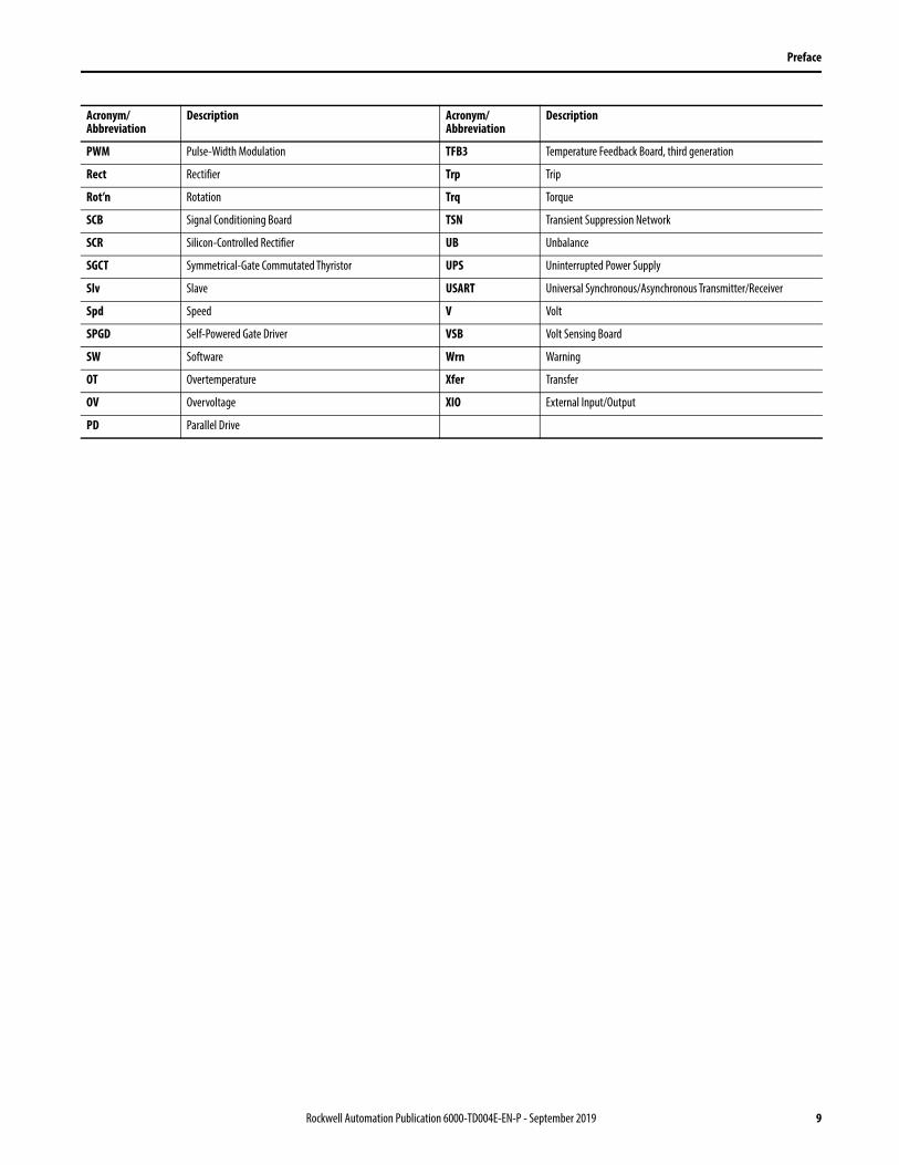
PWM Pulse-Width Modulation TFB3 Temperature Feedback Board, third generation
Rect Rectifier Trp Trip
Rot’n Rotation Trq Torque
SCB Signal Conditioning Board TSN Transient Suppression Network
SCR Silicon-Controlled Rectifier UB Unbalance
SGCT Symmetrical-Gate Commutated Thyristor UPS Uninterrupted Power Supply
Slv Slave USART Universal Synchronous/Asynchronous Transmitter/Receiver
Spd Speed V Volt
SPGD Self-Powered Gate Driver VSB Volt Sensing Board
SW Software Wrn Warning
OT Overtemperature Xfer Transfer
OV Overvoltage XIO External Input/Output
PD Parallel Drive
Acronym/ Abbreviation
Description Acronym/ Abbreviation
Description
Rockwell Automation Publication 6000-TD004E-EN-P - September 2019 9

Preface
Notes:
10 Rockwell Automation Publication 6000-TD004E-EN-P - September 2019

Chapter 1
Functional Descriptions
Introduction The PowerFlex 6000 is an adjustable speed AC drive that is suitable for new and retrofit centrifugal fan and pump applications. Air-cooled PowerFlex 6000 drives are designed to maximize energy efficiency by enabling soft-starting and variable-speed control in medium voltage, normal duty applications.
To achieve the low input harmonics and near-unity power factor that make this an ideal solution for standard motors, the drives use Cascaded “H’” Bridge (CHB) topology. This proven CHB topology combines an integrally mounted phase-shifting isolation transformer with series-connected power modules for each phase. Besides stepping down the input voltage, the isolation transformer also provides two other principal functions:
• Mitigate common mode voltage stress so motors with standard insulation levels can be used.
• Reduce Total Harmonic Distortion (THD), due to the phase shifting of its secondary windings, so input side harmonics don’t negatively impact the plant or utility power grid.
System Settings The system settings include the following functions:• Control Owner on page 12• HMI Display on page 14• Nameplate on page 15• Ramp on page 16• Rated Frequency on page 17• Stop Mode on page 17• Motor Direction Control on page 18• Switch Frequency Settings on page 18• Trends on page 19• VF Curve Setting on page 19
Rockwell Automation Publication 6000-TD004E-EN-P - September 2019 11

Chapter 1 Functional Descriptions
Control Owner
This function is used to switch the control source between Local, DCS, and Remote Box. The switch can be performed while the drive is online.
Three parameters are used to determine the control method and given frequency reference. The value range of Owner #1 Selection (P475) is “0 or 1”, the value range of Owner #2 Selection (P476) is “2...23”, and the value range of Owner #3 Selection (P477) is “18...23”. The default values for the parameters are “0, 8, and 23” respectively. The combinations are shown in the following table.
Table 1 - Frequency Reference and Control Command Source Matrix
The control command selections are:
1. Drive HMI or control panel buttons
2. Remote hardwired
3. Remote communications
4. Remote box buttons
The frequency reference selections are:
1. Local touch screen
2. Potentiometer on the control panel
3. Remote control analog 4-20 mA
4. Remote communications
5. 4-speed governor (Four frequency values are stored in parameters: 4-Step Variable Speed - Speed1 (P480), 4-Step Variable Speed - Speed2 (P481), 4- Step Variable Speed - Speed3 (P482), and 4-Step Variable Speed - Speed4 (P483))
6. Remote box buttons
Frequency Owner
Control Owner
HMI Comm /Local Button
DCS I/O DCS Comm Remote Box (Option)
HMI 0 6 12 18
Potentiometer0-10V (Option)
1 7 13 19
Analog 4-20 mA 2 8 14 20
Comm 3 9 15 21
4-Speed 4 10 16 22
Remote Box 5 11 17 23
12 Rockwell Automation Publication 6000-TD004E-EN-P - September 2019
Functional Descriptions Chapter 1
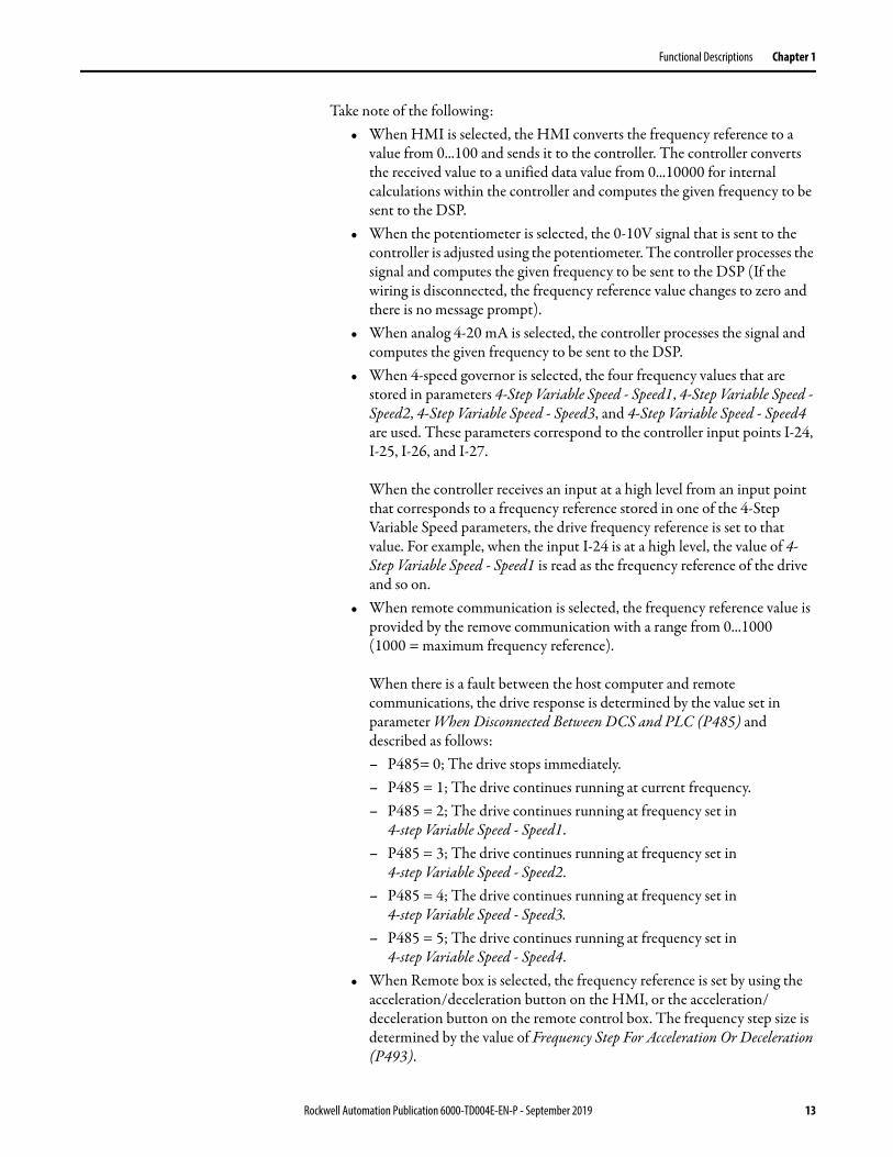
Take note of the following:• When HMI is selected, the HMI converts the frequency reference to a
value from 0...100 and sends it to the controller. The controller converts the received value to a unified data value from 0...10000 for internal calculations within the controller and computes the given frequency to be sent to the DSP.
• When the potentiometer is selected, the 0-10V signal that is sent to the controller is adjusted using the potentiometer. The controller processes the signal and computes the given frequency to be sent to the DSP (If the wiring is disconnected, the frequency reference value changes to zero and there is no message prompt).
• When analog 4-20 mA is selected, the controller processes the signal and computes the given frequency to be sent to the DSP.
• When 4-speed governor is selected, the four frequency values that are stored in parameters 4-Step Variable Speed - Speed1, 4-Step Variable Speed - Speed2, 4-Step Variable Speed - Speed3, and 4-Step Variable Speed - Speed4 are used. These parameters correspond to the controller input points I-24, I-25, I-26, and I-27.
When the controller receives an input at a high level from an input point that corresponds to a frequency reference stored in one of the 4-Step Variable Speed parameters, the drive frequency reference is set to that value. For example, when the input I-24 is at a high level, the value of 4-Step Variable Speed - Speed1 is read as the frequency reference of the drive and so on.
• When remote communication is selected, the frequency reference value is provided by the remove communication with a range from 0...1000(1000 = maximum frequency reference).
When there is a fault between the host computer and remote communications, the drive response is determined by the value set in parameter When Disconnected Between DCS and PLC (P485) and described as follows:– P485= 0; The drive stops immediately.– P485 = 1; The drive continues running at current frequency.– P485 = 2; The drive continues running at frequency set in
4-step Variable Speed - Speed1.– P485 = 3; The drive continues running at frequency set in
4-step Variable Speed - Speed2.– P485 = 4; The drive continues running at frequency set in
4-step Variable Speed - Speed3.– P485 = 5; The drive continues running at frequency set in
4-step Variable Speed - Speed4.• When Remote box is selected, the frequency reference is set by using the
acceleration/deceleration button on the HMI, or the acceleration/ deceleration button on the remote control box. The frequency step size is determined by the value of Frequency Step For Acceleration Or Deceleration (P493).
Rockwell Automation Publication 6000-TD004E-EN-P - September 2019 13
Chapter 1 Functional Descriptions
Switching between Local, DCS, or Remote box can be performed on the HMI, or using a selector switch mounted on the control panel. When Local/Remote Owner Selection (P478) is set to “1”, the selector switch is used. When Local/Remote Owner Selection is set to “0”, the HMI is used. When Local control method is selected, Owner #1 Selection is active. When DCS control method is selected, Owner #2 Selection is active. When Remote box control method is selected, Owner #3 Selection is active.
HMI Display
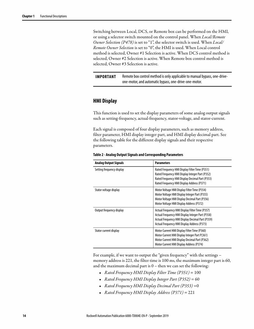
This function is used to set the display parameters of some analog output signals such as setting-frequency, actual-frequency, stator-voltage, and stator-current.
Each signal is composed of four display parameters, such as memory address, filter parameter, HMI display integer part, and HMI display decimal part. See the following table for the different display signals and their respective parameters.
Table 2 - Analog Output Signals and Corresponding Parameters
For example, if we want to output the “given frequency” with the settings – memory address is 221, the filter time is 100 ms, the maximum integer part is 60, and the maximum decimal part is 0 – then we can set the following:
• Rated Frequency HMI Display Filter Time (P351) = 100• Rated Frequency HMI Display Integer Part (P352) = 60• Rated Frequency HMI Display Decimal Part (P353) =0• Rated Frequency HMI Display Address (P371) = 221
IMPORTANT Remote box control method is only applicable to manual bypass, one-drive-one-motor, and automatic bypass, one-drive-one-motor.
Analog Output Signals Parameters
Setting frequency display Rated Frequency HMI Display Filter Time (P351)Rated Frequency HMI Display Integer Part (P352)Rated Frequency HMI Display Decimal Part (P353)Rated Frequency HMI Display Address (P371)
Stator voltage display Motor Voltage HMI Display Filter Time (P354)Motor Voltage HMI Display Integer Part (P355)Motor Voltage HMI Display Decimal Part (P356)Motor Voltage HMI Display Address (P372)
Output frequency display Actual Frequency HMI Display Filter Time (P357)Actual Frequency HMI Display Integer Part (P358)Actual Frequency HMI Display Decimal Part (P359)Actual Frequency HMI Display Address (P373)
Stator current display Motor Current HMI Display Filter Time (P360)Motor Current HMI Display Integer Part P(361)Motor Current HMI Display Decimal Part (P362)Motor Current HMI Display Address (P374)
14 Rockwell Automation Publication 6000-TD004E-EN-P - September 2019
Functional Descriptions Chapter 1
The values of the four parameters Rated Frequency HMI Display Address (P371), Motor Voltage HMI Display Address (P372), Actual Frequency HMI Display Address (P373), and Motor Current HMI Display Address (P374) need not be changed and can be left at their default values. The field support engineer can change them according to the specific case.
Nameplate
This function is used to set the basic parameters of motor, drive, transformer, and HECS. They are rated current, rated power, rated speed, rated power factor, number of motor pole pairs, and so on.
Number of Power Cells Per Phase (P007) is the amount of power cells in one phase.
For example, if the amount of power cells in one phase is five, then Number of Power Cells Per Phase must be set to five. The number of power cell’s fault information and warning information is based on Number of Power Cells Per Phase. If Number of Power Cells Per Phase is set to zero, then all power cell’s fault information and warning information is ignored. This allows the drive to be run in low voltage. This function can be used for checking of low voltage components and the control box.
Power Cell DC Bus Rated Voltage (P011) is the DC bus rated voltage of the power cell. Motor Rated Current (P199) is used for the fault judgment related motor current. The parameters Motor Rated Voltage (P012), Motor Rated Power (P013), Motor Rated Speed (P014), Motor Rated Power Factor (P015), and Number of Motor Pole Pairs (P017) are used for calculating the motor stator's parameters.
Encoder Resolution (P019), Line CT Ratio (P195), and Line CT Burden Resistor (P196). Motor HECS Ratio (P197) and Motor HECS Burden Resistor (P198) are used to calculate the Hall current sensor's rated current, which is used for the sampling of the drive's current (Line CT Ratio, Line CT Burden Resistor, Motor HECS Ratio, and Motor HECS Burden Resistor are set based on the AT board configuration).
IMPORTANT The value of this parameter must be set to the actual amount used in each phase.
Rockwell Automation Publication 6000-TD004E-EN-P - September 2019 15
Chapter 1 Functional Descriptions
Ramp
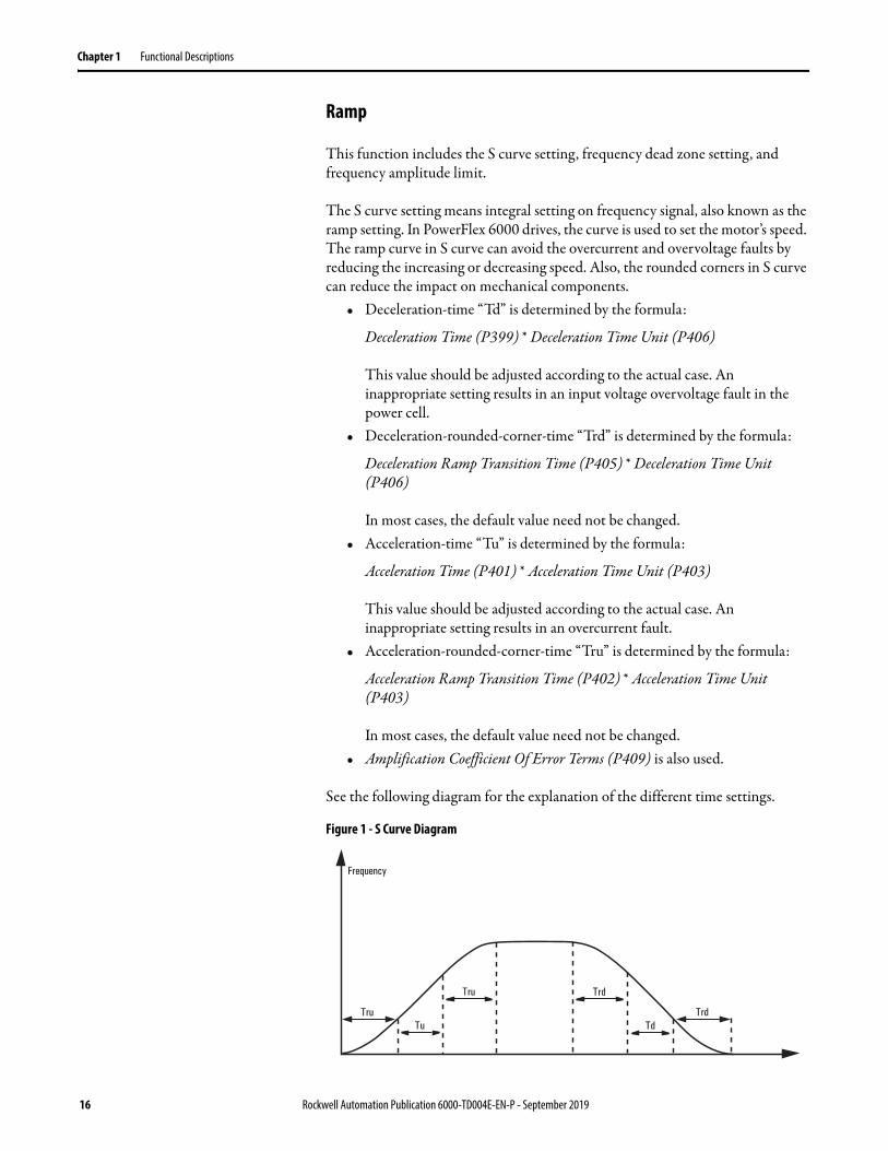
This function includes the S curve setting, frequency dead zone setting, and frequency amplitude limit.
The S curve setting means integral setting on frequency signal, also known as the ramp setting. In PowerFlex 6000 drives, the curve is used to set the motor’s speed. The ramp curve in S curve can avoid the overcurrent and overvoltage faults by reducing the increasing or decreasing speed. Also, the rounded corners in S curve can reduce the impact on mechanical components.
• Deceleration-time “Td” is determined by the formula:
Deceleration Time (P399) * Deceleration Time Unit (P406)
This value should be adjusted according to the actual case. An inappropriate setting results in an input voltage overvoltage fault in the power cell.
• Deceleration-rounded-corner-time “Trd” is determined by the formula:
Deceleration Ramp Transition Time (P405) * Deceleration Time Unit (P406)
In most cases, the default value need not be changed.• Acceleration-time “Tu” is determined by the formula:
Acceleration Time (P401) * Acceleration Time Unit (P403)
This value should be adjusted according to the actual case. An inappropriate setting results in an overcurrent fault.
• Acceleration-rounded-corner-time “Tru” is determined by the formula:
Acceleration Ramp Transition Time (P402) * Acceleration Time Unit (P403)
In most cases, the default value need not be changed.• Amplification Coefficient Of Error Terms (P409) is also used.
See the following diagram for the explanation of the different time settings.
Figure 1 - S Curve Diagram
Frequency
TruTu Td
Tru Trd
Trd
16 Rockwell Automation Publication 6000-TD004E-EN-P - September 2019

Functional Descriptions Chapter 1
Rated Frequency
This function is used to the set the drive's rated frequency parameters and also the frequency limit. Frequency dead zone setting is used to limit the low frequency starting range, and help prevent output fluctuations when the drive is in analog input mode and the frequency is around zero Hz. Frequency amplitude limit is used to limit the amplitude of set frequency, thus it helps prevent the set frequency from exceeding the drive's maximum output frequency.
Parameter Rated Output Frequency (P460) is the drive’s rated output frequency. The frequency value ranges from 0...75 Hz and should be set equal to the motor’s rated frequency. If Rated Output Frequency is not set correctly, it may cause damage to the motor.
Parameter Maximum Output Frequency (P466) is the drive’s maximum output frequency. Rated Output Frequency cannot be set higher than Maximum Output Frequency. Any attempt to do so fails.
If the original setting-frequency is lower than parameter Frequency Command Deadband Upper Limit (P414), frequency dead zone setting can change the setting-frequency to equal Frequency Command Deadband Upper Limit.
Frequency amplitude limit can limit the setting-frequency between parameters Frequency Command Lower Limit (P413) and Frequency Command Upper Limit (P415). Following the rule:
Frequency Command Upper Limit > Frequency Command Lower Limit > 0
This function is used to limit the amplitude for setting-frequency. This helps prevent the setting-frequency from becoming bigger than the drive’s maximum output frequency.
Stop Mode
There are two methods in which a PowerFlex 6000 drive can use to stop – ramp down and coast stop.
The stop mode can be selected by setting Stop Method (P024) to “1” for coast stop and “0” for ramp down.
If coast stop was selected, you must wait for a certain time to elapse before restarting the drive. The time is determined by the formula:
Time = Motor Coast Stop Time (P253) * frequency before stop / max frequency
If ramp down was selected, the motor ramps down.
Parameters Frequency Command-Low Frequency Region Boundary (P251) and Delayed Lockout Time of Stop Operation (P270) are also used in this function.
Rockwell Automation Publication 6000-TD004E-EN-P - September 2019 17

Chapter 1 Functional Descriptions
Motor Direction Control
This function is designed to work with other functions such as command source, motor rotation direction, switch frequency, and frequency command source selection.
The command source function is used to select the command source for starting, stopping, and resetting the drive.
The motor rotation direction function is used to change the motor's rotating direction without any hardware changing. There are two methods available in PowerFlex 6000. The offline method is performed locally and cannot be done when the motor is running. The online method is performed remotely and can be done using the DCS while the motor is running.
When Motor Rotation Direction Command Selection (P009) is set to “0”, it means offline local control, and the user can only change the motor’s rotating direction using the HMI when the drive is stopped. DCS control is disabled. To change the motor’s rotating direction, set parameter Motor Rotation Direction Under Local Control (P008) to “0” for reverse rotating or “1” for forward rotating.
When Motor Rotation Direction Command Selection (P009) is set to “1”, it means online remote control, and the user can change the motor’s rotating direction using the DCS while the drive is running. HMI control is disabled.
Switch Frequency Settings
The switch frequency function is used to set the switch frequency of the power semiconductor. The frequency command source selection function is used the select the given frequency mode.
Set parameter Switch Frequency Setting Enable Code (P087) to “0” to disable or “1” to enable the function.
Set parameter Switch Frequency Setting (P088) to “0” to set the switch frequency at 600 Hz or “1” to set the switch frequency at 1200 Hz.
IMPORTANT Set the Switch Frequency Setting Enable Code parameter back to zero after changing the Switch Frequency Setting parameter. The Switch Frequency Setting parameter can only be changed when offline.
18 Rockwell Automation Publication 6000-TD004E-EN-P - September 2019
Functional Descriptions Chapter 1
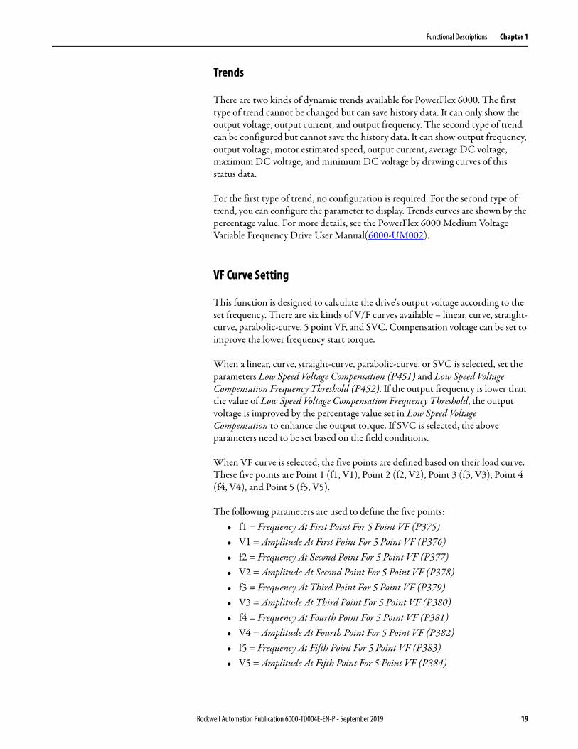
Trends
There are two kinds of dynamic trends available for PowerFlex 6000. The first type of trend cannot be changed but can save history data. It can only show the output voltage, output current, and output frequency. The second type of trend can be configured but cannot save the history data. It can show output frequency, output voltage, motor estimated speed, output current, average DC voltage, maximum DC voltage, and minimum DC voltage by drawing curves of this status data.
For the first type of trend, no configuration is required. For the second type of trend, you can configure the parameter to display. Trends curves are shown by the percentage value. For more details, see the PowerFlex 6000 Medium Voltage Variable Frequency Drive User Manual(6000-UM002).
VF Curve Setting
This function is designed to calculate the drive's output voltage according to the set frequency. There are six kinds of V/F curves available – linear, curve, straight-curve, parabolic-curve, 5 point VF, and SVC. Compensation voltage can be set to improve the lower frequency start torque.
When a linear, curve, straight-curve, parabolic-curve, or SVC is selected, set the parameters Low Speed Voltage Compensation (P451) and Low Speed Voltage Compensation Frequency Threshold (P452). If the output frequency is lower than the value of Low Speed Voltage Compensation Frequency Threshold, the output voltage is improved by the percentage value set in Low Speed Voltage Compensation to enhance the output torque. If SVC is selected, the above parameters need to be set based on the field conditions.
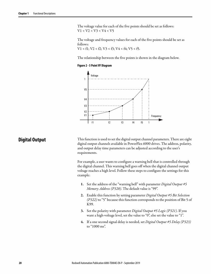
When VF curve is selected, the five points are defined based on their load curve. These five points are Point 1 (f1, V1), Point 2 (f2, V2), Point 3 (f3, V3), Point 4 (f4, V4), and Point 5 (f5, V5).
The following parameters are used to define the five points:• f1 = Frequency At First Point For 5 Point VF (P375)• V1 = Amplitude At First Point For 5 Point VF (P376)• f2 = Frequency At Second Point For 5 Point VF (P377)• V2 = Amplitude At Second Point For 5 Point VF (P378)• f3 = Frequency At Third Point For 5 Point VF (P379)• V3 = Amplitude At Third Point For 5 Point VF (P380)• f4 = Frequency At Fourth Point For 5 Point VF (P381)• V4 = Amplitude At Fourth Point For 5 Point VF (P382)• f5 = Frequency At Fifth Point For 5 Point VF (P383)• V5 = Amplitude At Fifth Point For 5 Point VF (P384)
Rockwell Automation Publication 6000-TD004E-EN-P - September 2019 19
Chapter 1 Functional Descriptions
The voltage value for each of the five points should be set as follows:V1 < V2 < V3 < V4 < V5
The voltage and frequency values for each of the five points should be set as follows:V1 < f1; V2 < f2; V3 < f3; V4 < f4; V5 < f5.
The relationship between the five points is shown in the diagram below.
Figure 2 - 5 Point VF Diagram
Digital Output This function is used to set the digital output channel parameters. There are eight digital output channels available in PowerFlex 6000 drives. The address, polarity, and output delay time parameters can be adjusted according to the user’s requirements.
For example, a user wants to configure a warning bell that is controlled through the digital channel. This warning bell goes off when the digital channel output voltage reaches a high level. Follow these steps to configure the settings for this example:
1. Set the address of the “warning bell” with parameter Digital Output #5 Memory Address (P320). The default value is “99”.
2. Enable this function by setting parameter Digital Output #5 Bit Selection (P322) to “5” because this function corresponds to the position of Bit 5 of K99.
3. Set the polarity with parameter Digital Output #5 Logic (P321). If you want a high-voltage level, set the value to “0”, else set the value to “1”.
4. If a one second signal delay is needed, set Digital Output #5 Delay (P323) to “1000 ms”.
f1
V1V2
V3
V4
V5
1Voltage
Frequency
f2 f3 f4 f5 1
20 Rockwell Automation Publication 6000-TD004E-EN-P - September 2019

Functional Descriptions Chapter 1
Table 3 - Digital Output Signal Parameter Setting Group
Analog Output This function is used to set the analog output channel. The analog signal can be output into 0-5V voltage or 4-20 mA current. There are four analog output channels available in PowerFlex 6000 drives – one for actual frequency variant, one for stator current variant, and the rest are reserved.
The selected variant undergoes a Low-Pass Filter, Amplitude-correction, and Amplitude-limitation process before the final result is output as a 0-5V and 4-20 mA analog signal. See the following diagram for the process.
Figure 3 - Analog Output Function Diagram
The actual frequency was filtered through the Low-Pass Filter with the filter time set to one second, amplitude scaling factor to 50%, offset to zero, and the output channel number is one.
Analog Output #1 Memory Address (P332) = 252Analog Output #1 Filter Time (P333) = 1000 msAnalog Output #1 Offset (P334) = 0Analog Output #1 Scaling Factor (P335) = 50.00%
Hardwired I/O Interface Description Related Parameters
I/O0 High voltage can be closed P300, P301, P302, P303
I/O1 System running P304, P305, P306, P307
I/O2 System fault P308, P309, P310, P311
I/O3 System trip P312, P313, P314, P315
I/O4 Warning P316, P317, P318, P319
I/O5 Warning bell P320, P321, P322, P323
I/O6 Customized trip P324, P325, P326, P327
I/O7 Pre-charge complete P328, P329, P330, P331
Low-pass Filter
Y = x / (P333 * s + 1)
Linear Transformation
Y = P335 * (x +P334)
Limit Amplitude
Digital/AnalogTransformation
0-5V
4-20 mA
Rockwell Automation Publication 6000-TD004E-EN-P - September 2019 21
Chapter 1 Functional Descriptions
Table 4 - Analog Output Display Parameter Setting Group
Drive Configuration The drive configuration includes the following functions:• Fan Control on page 22• Pre-charge Control on page 25• Customized Trip on page 27• Over Speed on page 28
Fan Control
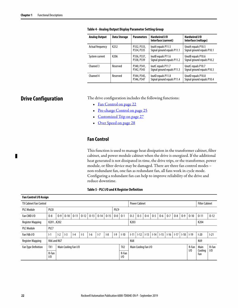
This function is used to manage heat dissipation in the transformer cabinet, filter cabinet, and power module cabinet when the drive is energized. If the additional heat generated is not dissipated in time, the drive trips, or the transformer, power module, or filter device may be damaged. There are three fan control modes – non-redundant fan, one fan as redundant fan, all fans work in cycle mode. Configuring a redundant fan can help to improve reliability of the drive and reduce downtime.
Table 5 - PLC I/O and K Register Definition
Analog Output Data Storage Parameters Hardwired I/O Interface (current)
Hardwired I/O Interface (voltage)
Actual frequency K252 P332, P333,P334, P335
IoutA equals P11.5Signal ground equals P11.1
UoutA equals P10.5Signal ground equals P10.1
System current K206 P336, P337,P338, P339
IoutB equals P11.6Signal ground equals P11.2
UoutB equals P10.6Signal ground equals P10.2
Channel 3 Reserved P340, P341,P342, P343
IoutC equals P11.7Signal ground equals P11.3
UoutC equals P10.7Signal ground equals P10.3
Channel 4 Reserved P344, P345,P346, P347
IoutD equals P11.8Signal ground equals P11.4
UoutD equals P10.8Signal ground equals P10.4
Fan Control I/O Assign
TX Cabinet Fan Control Power Cabinet Filter Cabinet
PLC Module PLC8 PLC9
Fan CMD I/O O-8 O-9 O-10 O-11 O-12 O-13 O-14 O-15 O-0 O-1 O-2 O-3 O-4 O-5 O-6 O-7 O-8 O-9 O-10 O-11 O-12
Register Mapping K201...K202 K203 K204
PLC Module PLC7
Fan Fdb I/O I-1 I-2 I-3 I-4 I-5 I-6 I-7 I-8 I-9 I-10 I-11 I-12 I-13 I-14 I-15 I-16 I-17 I-18 I-19 I-20 I-21
Register Mapping K66 and K67 K68 K69
Fan Type Definition TX1 Main Cooling Fan I/O TX2 Main Cooling Fan I/O R-Fan I/O
Main Cooling Fan
R-Fan I/O
R-Fan I/O
R-Fan I/O
22 Rockwell Automation Publication 6000-TD004E-EN-P - September 2019
Functional Descriptions Chapter 1
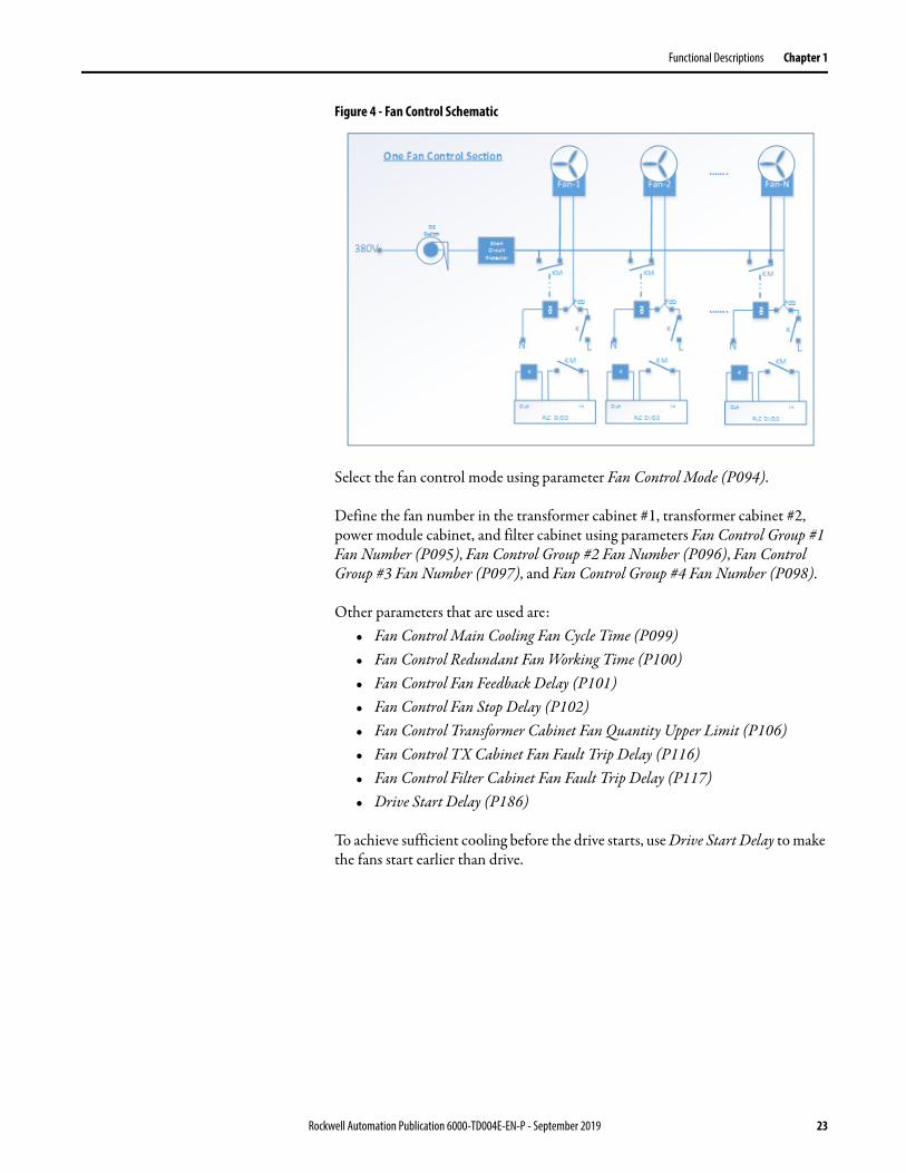
Figure 4 - Fan Control Schematic
Select the fan control mode using parameter Fan Control Mode (P094).
Define the fan number in the transformer cabinet #1, transformer cabinet #2, power module cabinet, and filter cabinet using parameters Fan Control Group #1 Fan Number (P095), Fan Control Group #2 Fan Number (P096), Fan Control Group #3 Fan Number (P097), and Fan Control Group #4 Fan Number (P098).
Other parameters that are used are:• Fan Control Main Cooling Fan Cycle Time (P099)• Fan Control Redundant Fan Working Time (P100)• Fan Control Fan Feedback Delay (P101)• Fan Control Fan Stop Delay (P102)• Fan Control Transformer Cabinet Fan Quantity Upper Limit (P106)• Fan Control TX Cabinet Fan Fault Trip Delay (P116)• Fan Control Filter Cabinet Fan Fault Trip Delay (P117)• Drive Start Delay (P186)
To achieve sufficient cooling before the drive starts, use Drive Start Delay to make the fans start earlier than drive.
Rockwell Automation Publication 6000-TD004E-EN-P - September 2019 23

Chapter 1 Functional Descriptions
The following diagrams show the work process of the fans in mode 1 and 2.
Figure 5 - Fan Work Process in Mode 1
Figure 6 - Fan Work Process in Mode 2
24 Rockwell Automation Publication 6000-TD004E-EN-P - September 2019
Functional Descriptions Chapter 1
Pre-charge Control
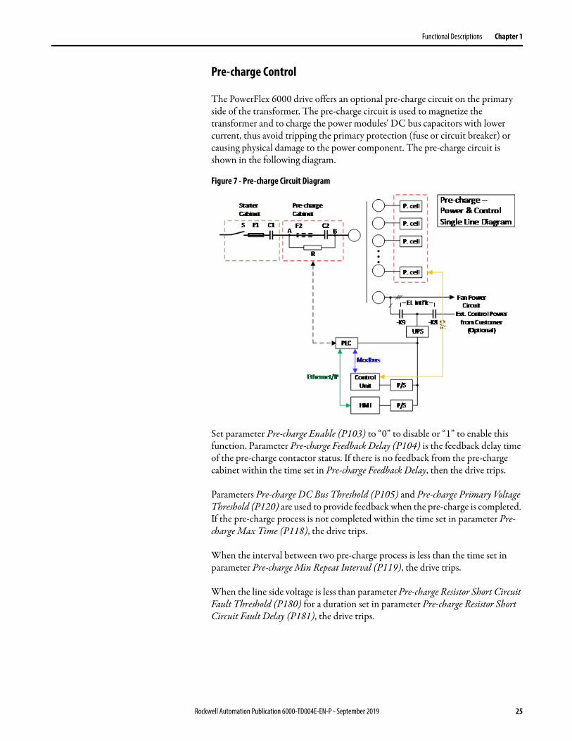
The PowerFlex 6000 drive offers an optional pre-charge circuit on the primary side of the transformer. The pre-charge circuit is used to magnetize the transformer and to charge the power modules' DC bus capacitors with lower current, thus avoid tripping the primary protection (fuse or circuit breaker) or causing physical damage to the power component. The pre-charge circuit is shown in the following diagram.
Figure 7 - Pre-charge Circuit Diagram
Set parameter Pre-charge Enable (P103) to “0” to disable or “1” to enable this function. Parameter Pre-charge Feedback Delay (P104) is the feedback delay time of the pre-charge contactor status. If there is no feedback from the pre-charge cabinet within the time set in Pre-charge Feedback Delay, then the drive trips.
Parameters Pre-charge DC Bus Threshold (P105) and Pre-charge Primary Voltage Threshold (P120) are used to provide feedback when the pre-charge is completed. If the pre-charge process is not completed within the time set in parameter Pre-charge Max Time (P118), the drive trips.
When the interval between two pre-charge process is less than the time set in parameter Pre-charge Min Repeat Interval (P119), the drive trips.
When the line side voltage is less than parameter Pre-charge Resistor Short Circuit Fault Threshold (P180) for a duration set in parameter Pre-charge Resistor Short Circuit Fault Delay (P181), the drive trips.
Rockwell Automation Publication 6000-TD004E-EN-P - September 2019 25

Chapter 1 Functional Descriptions
Cell Information Control
This function is used to read and write power cell parameters. There are two modes available – Read/write power cell parameters by power cell or read/write power cell parameters by parameter. The first mode reads all parameters from one power cell control board (PCCB). The second mode reads one parameter from all PCCBs and writes one parameter to all PCCBs. The following diagram shows the data flow between the PLC and DSP1. It also shows the frame of MPUC parameters, which is recalled by the PLC and shown in the HMI.
Figure 8 - Cell Information Control Diagram
Number of Power Cells Per Phase (P007) is the amount of power cells for each phase.
IMPORTANT The value of this parameter must be set to the actual amount used in each phase.
26 Rockwell Automation Publication 6000-TD004E-EN-P - September 2019
Functional Descriptions Chapter 1
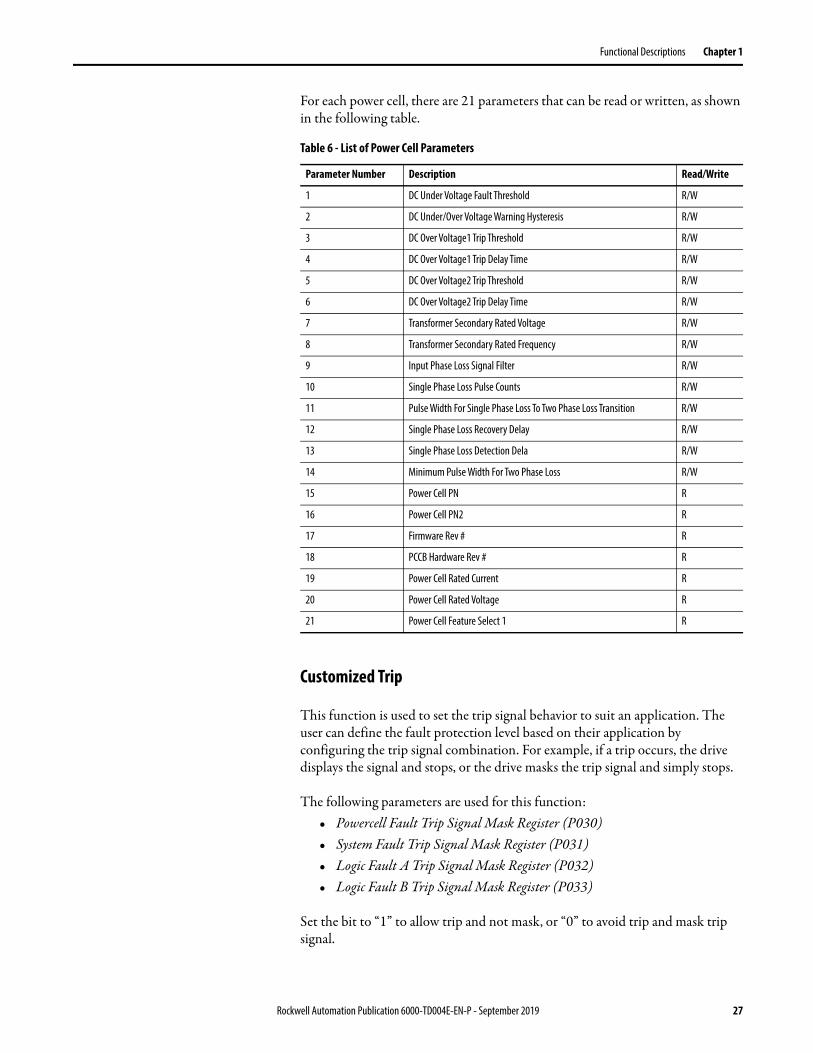
For each power cell, there are 21 parameters that can be read or written, as shown in the following table.
Table 6 - List of Power Cell Parameters
Customized Trip
This function is used to set the trip signal behavior to suit an application. The user can define the fault protection level based on their application by configuring the trip signal combination. For example, if a trip occurs, the drive displays the signal and stops, or the drive masks the trip signal and simply stops.
The following parameters are used for this function:• Powercell Fault Trip Signal Mask Register (P030)• System Fault Trip Signal Mask Register (P031)• Logic Fault A Trip Signal Mask Register (P032)• Logic Fault B Trip Signal Mask Register (P033)
Set the bit to “1” to allow trip and not mask, or “0” to avoid trip and mask trip signal.
Parameter Number Description Read/Write
1 DC Under Voltage Fault Threshold R/W
2 DC Under/Over Voltage Warning Hysteresis R/W
3 DC Over Voltage1 Trip Threshold R/W
4 DC Over Voltage1 Trip Delay Time R/W
5 DC Over Voltage2 Trip Threshold R/W
6 DC Over Voltage2 Trip Delay Time R/W
7 Transformer Secondary Rated Voltage R/W
8 Transformer Secondary Rated Frequency R/W
9 Input Phase Loss Signal Filter R/W
10 Single Phase Loss Pulse Counts R/W
11 Pulse Width For Single Phase Loss To Two Phase Loss Transition R/W
12 Single Phase Loss Recovery Delay R/W
13 Single Phase Loss Detection Dela R/W
14 Minimum Pulse Width For Two Phase Loss R/W
15 Power Cell PN R
16 Power Cell PN2 R
17 Firmware Rev # R
18 PCCB Hardware Rev # R
19 Power Cell Rated Current R
20 Power Cell Rated Voltage R
21 Power Cell Feature Select 1 R
Rockwell Automation Publication 6000-TD004E-EN-P - September 2019 27

Chapter 1 Functional Descriptions
Over Speed
This function is used to increase the speed above the motor’s rated frequency.
For example, a motor’s rated frequency is 50 Hz and the target frequency is 60 Hz. To accelerate the motor to the desired frequency, do the following:
1. Set the motor’s rated frequency with parameter Rated Output Frequency (P460) to “50”.
2. Set the target frequency with parameter Maximum Output Frequency (P466) to “60”.
3. Enable this function by setting parameter Over Speed Enable (P467) to “1”.
Figure 9 - Over Speed Function Diagram
Line Side The line side settings include the following functions:• Voltage Sag on page 29• Low Voltage Ride Through (LVRT) on page 30• Power Loss Auto Restart on page 30
Voltage
Constant magnetic Weak magnetic
Frequency
P456
U0
0 P460 P466
28 Rockwell Automation Publication 6000-TD004E-EN-P - September 2019

Functional Descriptions Chapter 1
When these three functions are all enabled, the behavior is shown in following diagram.
Figure 10 - Voltage Dip Withstand Capability
Voltage Sag
This function is used to make sure that the PowerFlex 6000 drive is able to work well when the input voltage drops to less than 30% of the required voltage. It includes the following subfunctions: voltage loop, flux regulation, and derating.
The voltage loop function uses the PI control method and is able to keep the output voltage equal with the given voltage dynamically if the input voltage sag is minor. If the input voltage sag is major, the PI controller enters saturation mode, and the output frequency drops down to a new, ideal value determined by theV/F controller. Also, the output frequency continues to drop to a new, ideal value. This is to avoid overheating of the input transformer.
To enable this function, set Voltage Loop Enable (P290) to “1”. If Flux Control Regulation Control Enable (P273) is set to “1”, the output frequency drops while the output voltage is kept at a constant value. This is to optimize the flux when the output voltage is smaller than the given voltage. If Flux Control Regulation Control Enable is set to “0”, the output frequency is kept at the given value, while the output voltage is kept at a constant value. The motor works in the “weak magnetic” mode during this time.
Rockwell Automation Publication 6000-TD004E-EN-P - September 2019 29

Chapter 1 Functional Descriptions
Low Voltage Ride Through (LVRT)
This function is used to make sure the PowerFlex 6000 drive does not trip when the input voltage drops (below 0.7 pu) or is cut off momentarily. Output current is limited to keep the power cell’s DC voltage at a high level and the running parameters of the motor is monitored during this period. When the input voltage is back to normal, the drive quickly recovers to the previous frequency before the low voltage condition occurred.
The parameter Low Voltage Ride Through Enable (P283) must be set to “1” to use this function. Low Voltage Ride Through Max Time Limit (P285) is the upper limit of the LVRT function. The default value is 5 cycles, and can be extended in special cases. However extending the time limit may lead to LVRT failure. The UPS must be open when using this function.
Power Loss Auto Restart
This function is used to restart the drive automatically after a power loss occurs for a long time. This function can be used together with the Low Voltage Ride Through function. The drive enters the PLR stage when the duration of the power loss exceeds the value of Low Voltage Ride Through Max Time Limit (P285).
The parameter Power Loss Restart Enable (P263) must be set to “1” to use this function. Power Loss Allowable Time (P264) is the upper limit of the Power Loss Restart function, and the value should not be set larger than Power Loss Time Max Limit (P265).
If the value of Power Loss Max Time Limit is set to less than the value of Power Loss Allowable Time, then the value of Power Loss Allowable Time is automatically reduced so that both values are identical. The maximum duration of the PLR stage is limited by both Power Loss Allowable Time and the working time of the UPS. The UPS must be open when using this function.
Figure 11 - Low Voltage Ride Through Diagram
IMPORTANT The running direction must not be changed during the “power loss, waiting recovery...” stage. Otherwise a “fault trip” fault occurs.
Inputvoltage
t=0 t=T
t<P264
Outputvoltage
Fly start
30 Rockwell Automation Publication 6000-TD004E-EN-P - September 2019
Functional Descriptions Chapter 1
Motor Side The motor side settings include the following function:• Bypass on page 31• Current Limit on page 35• Current Stability Loop on page 36• Flying Start on page 37• Load Loss Control on page 38• Motor Autotune on page 38• Restart Feature on page 39• Skip Frequency Settings on page 40• Start and Stop Sequence on page 40
Bypass
The bypass setting includes the following functions:• Cell Bypass on page 31• Bypass Mode Select on page 33• Automatically Switch to Bypass on page 34• Bypass to VFD on page 34• VFD to Bypass on page 35
Cell Bypass
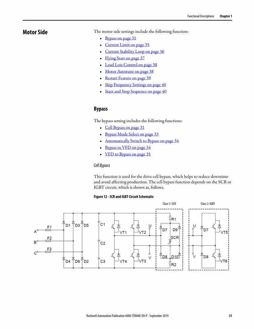
This function is used for the drive cell bypass, which helps to reduce downtime and avoid affecting production. The cell bypass function depends on the SCR or IGBT circuit, which is shown as, follows.
Figure 12 - SCR and IGBT Circuit Schematic
Class 1: SCR Class 2: IGBT
Rockwell Automation Publication 6000-TD004E-EN-P - September 2019 31
Chapter 1 Functional Descriptions
Only one cell bypass is allowed per phase, and it can be triggered by one of the following conditions:
• IGBT over current• Input over voltage in power cell• One phase loss• Cell overheat
To keep the line voltage balanced, each phase must bypass one cell simultaneously.
The following parameters are used for this function:• Power Cell Bypass Enable (P041)• Power Cell Bypass Delay After Power Cell Bypassed (P042)• Power Cell Bypass Upper Limit For Bypassed Feedback Time (P043)• Power Cell Bypass Fault Simulation Power Cell Count (P044)• Power Cell Bypass Upper Limit For Over Temperature (P057)• Power Cell Bypass Phase A Cell Number For Simulation (P058)• Power Cell Bypass Phase B Cell Number For Simulation (P059)• Power Cell Bypass Phase C Cell Number For Simulation (P060)• Power Cell Bypass Fault Simulation (P061)• Power Cell Bypass Enable Frequency Range Lower Limit (P065)• Power Cell Bypass Restart Enable After Power Cell Bypassed (P066)• One Phase Lost Filter Time (P068)• Power Cell Reactivation Time Upper Limit (P078)
Parameter Power Cell Bypass Enable must be set to “1” to use this function. The power cell count must not be less than three per phase, and the output frequency must be higher than the value set in Power Cell Bypass Enable Frequency Range Lower Limit. Under the above conditions, when any related fault occurs, the cell bypass is triggered.
Power Cell Bypass Restart Enable After Power Cell Bypassed is used to set the restart behavior after a cell bypass is triggered. Set the value to “1” to allow the drive to restart after a reset fault. Set the value to “0” to allow the drive to restart only after the power cell is repaired and control power is on again.
When the drive is running and a power cell faults (IGBT over current, input over voltage in power cell, one phase loss, cell overheat), a previously bypassed cell in the same phase that only has the “Bypass In Power Cell” fault can be restarted and bypass the faulty cell.
The cell bypass process is show in the following diagram.
32 Rockwell Automation Publication 6000-TD004E-EN-P - September 2019
Functional Descriptions Chapter 1
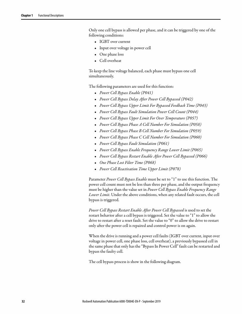
Figure 13 - Cell Bypass Process
For example, if Cell A5 faults, it is bypassed, and cells B5 and C5 are bypassed simultaneously. After that, the “Bypass in Power Cell” fault for cell C5 is removed and the cell is restarted when Cell C4 faults and is bypassed.
Bypass Mode Select
This function allows the drive to choose between five different bypass programs – no bypass, manually bypass, automatic one-to-one bypass, manual one-to-two bypass, and automatic one-to-two bypass. The bypass program can be selected by configuring parameter Bypass Mode Selection (P484).
To configure Bypass Mode Selection, the drive must be offline before selecting the desired option using the HMI or through remote communication. The selected bypass mode is displayed on the HMI.
• 0 = No bypass• 1 = Manual bypass• 2 = Automatic one-to-one bypass• 3 = Manual one-to-two bypass• 4 = Automatic one-to-two bypass
WARNING: For safety, the parameter Bypass Mode Selection cannot be changed when any MV switch is in the ON position. This parameter must be configured according to the actual bypass scheme used.
Rockwell Automation Publication 6000-TD004E-EN-P - September 2019 33
Chapter 1 Functional Descriptions
Automatically Switch to Bypass
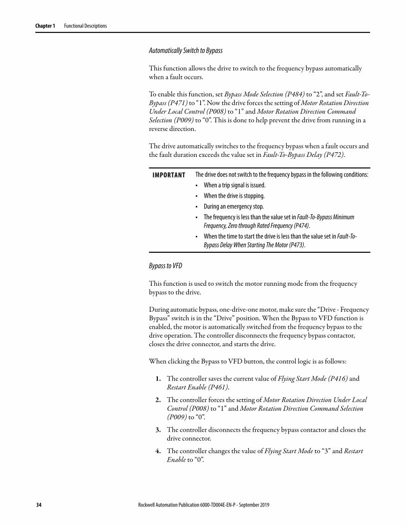
This function allows the drive to switch to the frequency bypass automatically when a fault occurs.
To enable this function, set Bypass Mode Selection (P484) to “2”, and set Fault-To-Bypass (P471) to “1”. Now the drive forces the setting of Motor Rotation Direction Under Local Control (P008) to “1” and Motor Rotation Direction Command Selection (P009) to “0”. This is done to help prevent the drive from running in a reverse direction.
The drive automatically switches to the frequency bypass when a fault occurs and the fault duration exceeds the value set in Fault-To-Bypass Delay (P472).
Bypass to VFD
This function is used to switch the motor running mode from the frequency bypass to the drive.
During automatic bypass, one-drive-one motor, make sure the “Drive - Frequency Bypass” switch is in the “Drive” position. When the Bypass to VFD function is enabled, the motor is automatically switched from the frequency bypass to the drive operation. The controller disconnects the frequency bypass contactor, closes the drive connector, and starts the drive.
When clicking the Bypass to VFD button, the control logic is as follows:
1. The controller saves the current value of Flying Start Mode (P416) and Restart Enable (P461).
2. The controller forces the setting of Motor Rotation Direction Under Local Control (P008) to “1” and Motor Rotation Direction Command Selection (P009) to “0”.
3. The controller disconnects the frequency bypass contactor and closes the drive connector.
4. The controller changes the value of Flying Start Mode to “3” and Restart Enable to “0”.
IMPORTANT The drive does not switch to the frequency bypass in the following conditions:• When a trip signal is issued.• When the drive is stopping.• During an emergency stop.• The frequency is less than the value set in Fault-To-Bypass Minimum
Frequency, Zero through Rated Frequency (P474).• When the time to start the drive is less than the value set in Fault-To-
Bypass Delay When Starting The Motor (P473).
34 Rockwell Automation Publication 6000-TD004E-EN-P - September 2019

Functional Descriptions Chapter 1
5. The controller starts the drive.
VFD to Bypass
This function is used switch the motor running mode from the drive to the frequency bypass.
During automatic bypass, one-drive-one-motor, when the VFD to Bypass function is enabled, regardless of whether the drive is in Local or Remote control mode, the drive automatically sets the frequency to the rated frequency and save the current value of Stop Method (P024). Then it sets the value of Stop Method to “1”, Motor Rotation Direction Under Local Control (P008) to “1”, and Motor Rotation Direction Command Selection (P009) to “0”.
When the actual frequency is equal to the rated frequency the controller disconnects the drive contactor, then after the time set in Fault-To-Bypass (P472) has elapsed, closes the bypass contactor so that the motor starts running, and Stop Method is restored to its original value.
Current Limit
This function is used to help prevent the motor from being overloaded for a long time, and to help protect the motor and drive. When the motor is overloaded, the drive ramps down until the output current RMS value is lower than the drive setting. This feature can also be used to limit the ramp up current.
For current limit, the over load time, over load extent, and over load period can be defined. This function can suppress current spikes, which are caused by changes in transient load.
The following parameters are used for this function:• Current Limitation Enable (P436)• Current Limitation Enable Frequency Range Lower Limit (P438)• Current Limitation Threshold (P441)• Current Limitation Heating Time (P442)• Current Limitation Cooling Time (P443)• Current Limitation Decel Ramp Slope Change (P444)• Current Limitation Cycle Load Control Enable (P445)• Current Limit Loop Kp (P133)
IMPORTANT After clicking the Bypass to VFD button and a delay of 60 seconds has passed, parameters Flying Start Mode and Restart Enable are restored to their original values.After performing the Bypass to VFD function, there is a 60 second delay before you can perform the VFD to Bypass function or Reset operation. This is to help prevent errors such as internal parameters not being restored, no response after clicking the VFD to Bypass button, and so on.
Rockwell Automation Publication 6000-TD004E-EN-P - September 2019 35

Chapter 1 Functional Descriptions
• Current Limit Loop Ki (P134)• Current Limit Loop Kd (P135)
When the output current is higher than the value of parameter Current Limitation Threshold, the over load timer is triggered and the current limit is set to the value of parameter Current Limitation Decel Ramp Slope Change. Once the duration reaches the value of parameter Current Limitation Heating Time, the current limit is set to the value of parameter Current Limitation Threshold.
When the output current is lower than the value of parameter Current Limitation Threshold, the cooling timer is triggered. Once the duration reaches the value of parameter Current Limitation Cooling Time, the current limit is set to the value of parameter Current Limitation Threshold.
Figure 14 - Current Limit Diagram
Current Stability Loop
This function is used to solve current oscillation at low speed stator resistance effect and output deadband effect.
The following parameters are used for this function:• Current Stability Loop Filter Time Constant (P034)• Current Stability Loop Output Scaling Factor (P035)• Current Stability Loop Output Upper Limit (P036)• Current Stability Loop Output Lower Limit (P037)• Current Stability Loop Enable (P038)• Current Stability Loop Enable Frequency Range Upper Limit (P039)• Current Stability Loop Enable Frequency Range2 Upper Limit (P069)
36 Rockwell Automation Publication 6000-TD004E-EN-P - September 2019
Functional Descriptions Chapter 1
• Current Stability Loop Frequency Range2 Output Scaling Factor (P070)• Current Stability Loop Frequency Range3 Output Scaling Factor (P071)• Current Stability Loop Enable Delay (P072)
In most cases, the default parameter values need not be changed.
Flying Start
This function is used to enable a fast motor restart without having to stop the motor. There are three Flying Start modes available in PowerFlex 6000 – search frequency from setting-frequency, search frequency from last stop frequency plus five Hz, and search frequency from maximum frequency.
The Flying Start function can identify the motor speed based on the output current.
The following parameters may need to be adjusted based on your application:• Flying Start-Initial Output Voltage Percentage (P113)• Flying Start-Current Comparison Delay For Motor Speed Search (P114)• Flying Start-Current Threshold For Successful Motor Speed Search (P115)• Flying Start Compensation Enable (P393)• Flying Start Compensation Current Threshold (P394)• Flying Start Compensation Frequency Reduce Speed (P395)• Flying Start Compensation Defer Restore Voltage Speed Current Threshold
(P408)• Flying Start Compensation Current Threshold for Fast Compensation
(P410)• Flying Start Mode (P416)• Flying Start Motor Speed Search Timeout (P417)• Flying Start Voltage Recovery Time (Low Speed Region) (P457)• Flying Start Voltage Recovery Time (High Speed Region) (P459)• Flying Start Low/High Speed Regions Boundary (P463)
In most cases, the default parameter values need not be changed.
Here are some tips to use the function more effectively. If the drive is unable to detect the correct speed setting, increase Flying Start Motor Speed Search Timeout to decrease the search steps and improve the accuracy, or increase Flying Start-Initial Output Voltage Percentage and decrease Flying Start-Current Threshold For Successful Motor Speed Search to improve the accuracy. If there was some noise during the restore stage, increase Flying Start Voltage Recovery Time (Low Speed Region) or Flying Start Voltage Recovery Time (High Speed Region). It is not necessary to change Flying Start Low/High Speed Regions Boundary.
Rockwell Automation Publication 6000-TD004E-EN-P - September 2019 37

Chapter 1 Functional Descriptions
The frequency compensation feature should be enabled if static fly start is required to help prevent “output short circuit” fault from occurring. The value of Flying Start Compensation Frequency Reduce Speed should not be set too small, especially if there is a large amount of inertia present. The default value is sufficient for general-purpose applications.
Use the third Flying Start mode, “search frequency from maximum frequency” to implement AC mode to VF mode.
Load Loss Control
This function is used to avoid motor regeneration. In normal operation, there is a quick acceleration of motor speed when there is a sudden loss or heavy reduction of load. At this time, the motor works in regeneration mode and the DC bus of the power cell is charging which leads to power cell over voltage.
The following parameters are used for this function:• Load Loss Control Enable (P045)• Load Loss Enable Frequency (P046)• Load Loss Control Differential Scaling (P047)• Load Loss Frequency Compensation Upper Limit (P048)• Load Loss Control Scaling Factor (P049)• Load Loss Control Integral Time (P050)• Load Loss Control Filter Time (P051)• Load Loss Enable Current Threshold (P052)• Load Loss Control Exit Delay (P053)
Motor Autotune
This function is used to measure the motor parameters and it can calculate the values automatically or by nameplate. The motor parameters can be set manually but it is recommended to set them automatically to achieve system performance. The motor parameters include motor stator, motor rotor, and motor magnetizing current.
The following parameters are used for this function:• Motor Autotune Selection (P121)• Motor Autotune Delay (P122)• Motor Autotune Filter Time (P123)• Motor Autotune Current Id Kp (P124)• Motor Autotune Current Id Ki (P125)• Motor Autotune Current Iq Kp (P126)• Motor Autotune Current Iq Ki (P127)• Motor Autotune Id Feedback Error Valid (P128)
38 Rockwell Automation Publication 6000-TD004E-EN-P - September 2019

Functional Descriptions Chapter 1
• Motor Autotune Lr/Lm (P129)• Motor Autotune Id Reference (P130)• Motor Autotune Iq Reference (P131)• Motor Autotune Time Limit (P132)• Motor Autotune Rs/Rr (P136)• Motor Rated Current (P137)• Motor Stator Resistance Rs (P138)• Motor Magnetizing Current Id (P139)• Motor Rotor Resistance Rr (P140)• Motor Magnetizing Inductance Lm (P141)• Motor Stator Leakage Inductance LIs (P142)• Motor Rotor Leakage Inductance Llr (P143)• Motor Autotune Rs Upper Limit (P178)• Motor Autotune Maximum Iq For No Load (P179)
Use parameter Motor Autotune Selection to select the motor autotune mode. There are four modes – manual configuration, nameplate configuration, static autotune, and dynamic autotune.
Restart Feature
This function is used to restart the drive automatically after a system fault occurs. This helps to improve drive stability and avoids disruption in some applications should the drive stop unexpectedly.
To enable the drive restart function, set Restart Enable (P461) to “1”. If something is wrong with the power cell, the function waits for the time set in Power Cell Fault Auto Reset Delay (P465) to elapse before restarting. If any fault occurs twice during the time set in Fault Reset Timeout (P462), the drive trips.
IMPORTANT If the restart feature is enabled, Flying Start mode must also be enabled and set to “Search frequency from last stop frequency plus five Hz”.
Rockwell Automation Publication 6000-TD004E-EN-P - September 2019 39
Chapter 1 Functional Descriptions
Skip Frequency Settings
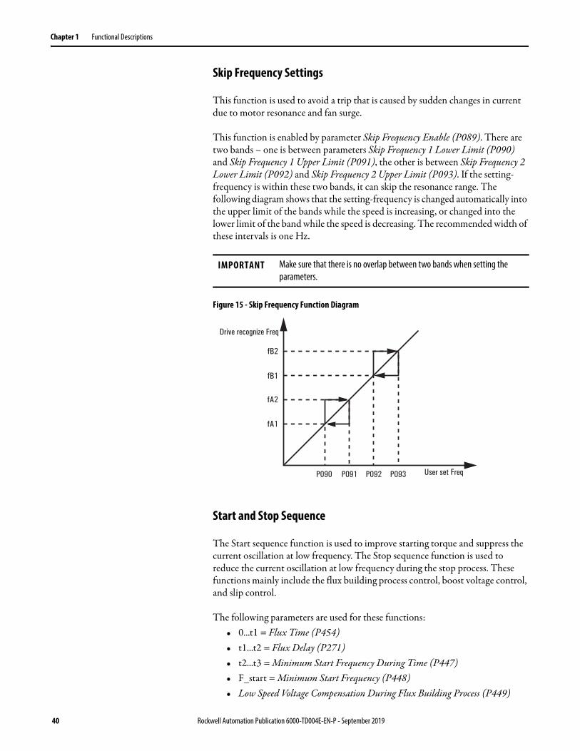
This function is used to avoid a trip that is caused by sudden changes in current due to motor resonance and fan surge.
This function is enabled by parameter Skip Frequency Enable (P089). There are two bands – one is between parameters Skip Frequency 1 Lower Limit (P090) and Skip Frequency 1 Upper Limit (P091), the other is between Skip Frequency 2 Lower Limit (P092) and Skip Frequency 2 Upper Limit (P093). If the setting-frequency is within these two bands, it can skip the resonance range. The following diagram shows that the setting-frequency is changed automatically into the upper limit of the bands while the speed is increasing, or changed into the lower limit of the band while the speed is decreasing. The recommended width of these intervals is one Hz.
Figure 15 - Skip Frequency Function Diagram
Start and Stop Sequence
The Start sequence function is used to improve starting torque and suppress the current oscillation at low frequency. The Stop sequence function is used to reduce the current oscillation at low frequency during the stop process. These functions mainly include the flux building process control, boost voltage control, and slip control.
The following parameters are used for these functions:• 0...t1 = Flux Time (P454)• t1...t2 = Flux Delay (P271)• t2...t3 = Minimum Start Frequency During Time (P447)• F_start = Minimum Start Frequency (P448)• Low Speed Voltage Compensation During Flux Building Process (P449)
IMPORTANT Make sure that there is no overlap between two bands when setting the parameters.
Drive recognize Freq
User set Freq
fB2
fB1
fA2
fA1
P090 P091 P092 P093
40 Rockwell Automation Publication 6000-TD004E-EN-P - September 2019

Functional Descriptions Chapter 1
• Low Speed Voltage Compensation (P451)• Low Speed Voltage Compensation Threshold (P464)
Figure 16 - Start and Stop Sequence Diagram
Process Control The process control settings include the following functions:• Deceleration and Acceleration Process User Define on page 41• PID Function on page 43• Deceleration Control on page 44
Deceleration and Acceleration Process User Define
This function allows you to define the deceleration and acceleration process into four steps to suit your application.
The drive decelerates from rated frequency to Freq1 during t1, from Freq1 to Freq2 during t2, from Freq2 to Freq3 during t3, and from Freq3 to zero during t4.
The following parameters are used to define the deceleration process:• Freq1 = Deceleration Frequency 1 (P387)• Freq2 = Deceleration Frequency 2 (P389)• Freq3 = Deceleration Frequency 3 (P391)• t1 = Deceleration Time 1 (P386)• t2 = Deceleration Time 2 (P388)
IMPORTANT It is recommended to use these functions when the drive is not in SVC mode.
Rockwell Automation Publication 6000-TD004E-EN-P - September 2019 41

Chapter 1 Functional Descriptions
• t3 = Deceleration Time 3 (P390)• t4 = Deceleration Time 4 (P392)
The following parameters are used to define the acceleration process:• Freq1 = Acceleration Frequency 1 (P419)• Freq2 = Acceleration Frequency 2 (P421)• Freq3 = Acceleration Frequency 3 (P423)• t1 = Acceleration Time 1 (P418)• t2 = Acceleration Time 2 (P420)• t3 = Acceleration Time 3 (P422)• t4 = Acceleration Time 4 (P424)
The following rule must be observed for both deceleration and acceleration:
Freq1 > Freq2 > Freq3
Parameter Deceleration Process Enable (P385) must be set to “1” to use this function. The total deceleration time is equal to:Deceleration Time 1 + Deceleration Time 2 + Deceleration Time 3 + Deceleration Time 4
If Deceleration Process Enable is set to “0”, the deceleration time is equal to the value set in Deceleration Time (P399).
Parameter Acceleration Process Enable (P425) must be set to “1” to use this function. The total acceleration time is equal to:Acceleration Time 1 + Acceleration Time 2 + Acceleration Time 3 + Acceleration Time 4
If Acceleration Process Enable is set to “0”, the acceleration time is equal to the value set in Acceleration Time (P401).
Figure 17 - Deceleration and Acceleration Process Diagram
Deceleration Acceleration
42 Rockwell Automation Publication 6000-TD004E-EN-P - September 2019

Functional Descriptions Chapter 1
PID Function
This function allows you to control the production process and process feedback signal to the drive to achieve PID process control.
To use the PID function:
1. Set PID Control Enable (P486) to “1”.There is only the negative feedback function, there is no positive feedback function.
2. Select the reference signalIf PID Control Enable is set to “1”, the frequency reference channel is disabled and the PID reference channel is enabled. In the hardware, both frequency reference and PID reference share the same channel.
3. PID reference signalThe drive PID digital and analog reference signals are shown in the following diagram.
a. Digital reference signalWhen the drive is in the Local control method (Owner #1 Selection (P475) = “1”), the signal is provided by the HMI and the data range is from 0...100.0.
When the drive is in the Remote control method (Owner #2 Selection (P476) = “15”), the signal is provided by communications and the data range is from 0...1000 (1000 = upper range limit * 10).
b. Analog reference signalWhen the drive is in the Remote control method (Owner #2 Selection (P476) = “8”), the signal is provided by the 4-20 mA input.
P475=0
P476=15
P476=8
0.0...100.0 PID Function Switch
Negative Feedback0...1000
4-20 mA
HMI
Normalization
Comm
Analog
Local
Remote
P
I
D
Drive
PID Reference
FrequencyReference Frequency
ReferenceControlTarget
Feedback
IMPORTANT Take note of the following:• Failure during frequency-to-power conversion and power-to-
frequency conversion functions.• Fault automatic conversion function is retained.
Rockwell Automation Publication 6000-TD004E-EN-P - September 2019 43
Chapter 1 Functional Descriptions
Deceleration Control
This function is used to avoid motor charging back to DC bus during ramp down, and DC bus over voltage trip.
The following parameters are used for this function:• Deceleration Control Enable (P396)• Deceleration Control Active Power Level for Release Output Frequency
(P397)• Deceleration Control Active Power Level for Hold On Output Frequency
(P398)• Deceleration Control Compensation Threshold Scaling Factor (P434)• Deceleration Control Frequency Range (P435)
During the ramp down process, if active power is lower than Deceleration Control Active Power Level for Hold On Output Frequency plus active power threshold, the drive output frequency is held. However if active power is higher than Deceleration Control Active Power Level for Release Output Frequency plus active power threshold, the ramp down process continues.
Protection Protection includes faults and warnings. Faults include system faults, logic faults, and power cell faults. Warnings include system warnings, logic warnings, and power cell warnings. For more information, see Fault Messages on page 203 and Warning Messages on page 211.
44 Rockwell Automation Publication 6000-TD004E-EN-P - September 2019
Chapter 2
Parameter Descriptions
PowerFlex 6000 Medium Voltage AC DriveDatabase Revision # 6.xxx This document provides detailed description of the parameters used in drive
control. The parameters are arranged into functional groups. Each description begins with the full name of the parameter. The linear number of the parameter is given followed by the default value, then the minimum and maximum values showing the position of the decimal point and the units if applicable. Next is the generic value that is assigned when a parameter initialization is performed. The access level at which the parameter can be first seen is given. The access levels are User, Setup, and R&D. If the parameter is first seen at a certain level and it is a Read/Write type, it can be modified at the same or a higher level. Read only parameters are operational variables that change with different operating conditions. Finally, there is a short functional description of the parameter.
IMPORTANT Please read the following information on overall parameter configuration.
Rockwell Automation Publication 6000-TD004E-EN-P - September 2019 45

Chapter 2 Parameter Descriptions
Interpreting Bit-Encoded Parameters
Most bit-encoded parameters follow a basic format. A one (1) in an associated bit represents a true or active condition. A zero (0) in an associated bit represents a false or inactive condition.
The methodology is best illustrated using an example:
Power Cell Fault MaskLinear Number: P010Default Value: 32767Minimum Value: 0Maximum Value: 32767Access Level: R&DRead/Write: Read/WriteModify Level: Online/Offline
This parameter allows user to select which faults related to a power cell can be masked.
The description in the manual will always be structured in the same way. The top description (in this case, IGBT set#1 over current in powercell) is always the least-significant bit, or right-most bit. As you move down the list of descriptions, you move to the left on the bit-encoded word. Any unused bits in the middle of a word will be identified, but unused bits in the middle of a word will have no description. This is why a 16-bit word may only have a few descriptions. The rest are reserved for future expansion.
When a bit-encoded parameter is viewed in its associated group, it is actually displayed as a hexadecimal number. The right-most four bits represent the right-most hexadecimal digit. Each subsequent group of 4 represents the next hex digit.
Bit Enum Text Description
0 IGBT set#1 over current in powercell 1 = Over current, 0 = Normal
1 IGBT set#2 over current in powercell 1 = Over current, 0 = Normal
2 Input over voltage in powercell 1 = Over voltage, 0 = Normal
3 DC Bus under voltage in powercell 1 = Low voltage, 0 = Normal
4 Abnormal communication in powercell 1 = Abnormal, 0 = Normal
5 No PWM1 pulse for IGBT set#1 in powercell 1 = Abnormal, 0 = Normal
6 No PWM2 pulse for IGBT set#2 in powercell 1 = Abnormal, 0 = Normal
7 IGBT set#1 failed to turn on in powercell Reserved
8 IGBT set#2 failed to turn on in powercell Reserved
9 Powercell bypass 1 = Abnormal, 0 = Normal
10 Over temperature in powercell 1 = Abnormal, 0 = Normal
11 Powercell failed to bypass 1 = Abnormal, 0 = Normal
12 One phase Lost in powercell 1 = Abnormal, 0 = Normal
13 Two phase Lost in powercell 1 = Abnormal, 0 = Normal
14 Input over voltage warning in powercell 1 = Abnormal, 0 = Normal
15 Reserved
46 Rockwell Automation Publication 6000-TD004E-EN-P - September 2019

Parameter Descriptions Chapter 2
The following table illustrates the relationship:
When you display a specific bit-encoded parameter, or choose to modify a bit-encoded parameter, it will be displayed in bit format, with an individual description of each bit. When modifying a parameter, highlighting the bit with the cursor keys will automatically pop up the description on screen.
Conversion Table
Bit 15 14 13 12 11 10 9 8 7 6 5 4 3 2 1 0
Value 8 4 2 1 8 4 2 1 8 4 2 1 8 4 2 1
Example 0 1 0 1 1 1 1 0 1 0 1 1 0 0 1 1
0 + 4 + 0 + 1 8 + 4 + 2 + 0 8 + 0 + 2 + 1 0 + 0 + 2 + 1
Sums 5 E B 3
Binary Hex Binary Hex Binary Hex Binary Hex
0000 0 0100 4 1000 8 1100 C
0001 1 0101 5 1001 9 1101 D
0010 2 0110 6 1010 A 1110 E
0011 3 0111 7 1011 B 1111 F
Rockwell Automation Publication 6000-TD004E-EN-P - September 2019 47

Chapter 2 Parameter Descriptions
Control Owner Parameters Owner #1 SelectionLinear Number: P475Default Value: 0Minimum Value: 0Maximum Value: 1Access Level: Setup, R&DRead/Write: Read/WriteModify Level: Online/Offline
This parameter is used to select the Frequency Reference source and Control Command source when the drive control mode is set to Local (mainly refers to the Start command).
Owner #2 SelectionLinear Number: P476Default Value: 8Minimum Value: 2Maximum Value: 23Access Level: Setup, R&DRead/Write: Read/WriteModify Level: Online/Offline
This parameter is used to select the Frequency Reference source and Control Command source when the drive control mode is set to DCS (mainly refers to the Start command).
For example, when P476 is set to ‘8’, the analog value of 4-20 mA is set by the DCS as the Frequency Reference of the drive and the hard Start mode is controlled by the DCS. When P476 is set to “6”, the HMI is set as the Frequency Reference of the drive and the hard Start mode is controlled by the DCS through hard wiring.
Value Description
0 Frequency Reference is from the HMI, and Control Command is from the HMI or Control Panel.
1 Frequency Reference is from the drive Potentiometer, and Control Command is from the HMI or Control Panel.
Table 7 - Frequency Reference and Control Command Source Matrix for Parameter P476
Frequency Owner
Control Owner
HMI Comm /Local Button
DCS I/O DCS Comm Remote Box (Option)
HMI 0 6 12 18
Potentiometer0-10V (Option)
1 7 13 19
Analog 4-20 mA 2 8 14 20
Comm 3 9 15 21
4-Speed 4 10 16 22
Remote Box 5 11 17 23
48 Rockwell Automation Publication 6000-TD004E-EN-P - September 2019

Parameter Descriptions Chapter 2
Owner #3 SelectionLinear Number: P477Default Value: 23Minimum Value: 18Maximum Value: 23Access Level: Setup, R&DRead/Write: Read/WriteModify Level: Online/Offline
This parameter is used to select the Frequency Reference source and Control Command source when the drive control mode is set to Remote Box (mainly refers to the Start command).
Local/Remote Owner SelectionLinear Number: P478Default Value: 0Minimum Value: 0Maximum Value: 3Access Level: Setup, R&DRead/Write: Read/WriteModify Level: Offline only
This parameter is used to set the location to switch the drive control mode between Local, DCS, and Remote box.
Table 8 - Frequency Reference and Control Command Source Matrix for Parameter P477
Frequency Owner
Control Owner
HMI Comm /Local Button
DCS I/O DCS Comm Remote Box (Option)
HMI N/A N/A N/A 18
Potentiometer0-10V (Option)
N/A N/A N/A 19
Analog 4-20 mA N/A N/A N/A 20
Comm N/A N/A N/A 21
4-Speed N/A N/A N/A 22
Remote Box N/A N/A N/A 23
Value Description
0 Selection is done on the HMI.
1 Selection is done using a switch mounted on the control panel.
2 Selection is done on the HMI and a switch mounted on the user site.
3 Selection is done using a switch mounted on the control panel and a switch on the user site.
Rockwell Automation Publication 6000-TD004E-EN-P - September 2019 49

Chapter 2 Parameter Descriptions
4-Step Variable Speed – Speed1Linear Number: P480Default Value: 10Minimum Value: 0Maximum Value: 75Access Level: Setup, R&DRead/Write: Read/WriteModify Level: Online/Offline
This parameter sets the frequency value of the first step in the 4-step Variable Speed function.
4-Step Variable Speed – Speed2Linear Number: P481Default Value: 20Minimum Value: 0Maximum Value: 75Access Level: Setup, R&DRead/Write: Read/WriteModify Level: Online/Offline
This parameter sets the frequency value of the second step in the 4-step Variable Speed function.
4-Step Variable Speed – Speed3Linear Number: P482Default Value: 30Minimum Value: 0Maximum Value: 75Access Level: Setup, R&DRead/Write: Read/WriteModify Level: Online/Offline
This parameter sets the frequency value of the third step in the 4-step Variable Speed function.
4-Step Variable Speed – Speed4Linear Number: P483Default Value: 40Minimum Value: 0Maximum Value: 75Access Level: Setup, R&DRead/Write: Read/WriteModify Level: Online/Offline
This parameter sets the frequency value of the fourth step in the 4-step Variable Speed function.
50 Rockwell Automation Publication 6000-TD004E-EN-P - September 2019

Parameter Descriptions Chapter 2
When Disconnected Between DCS and PLCLinear Number: P485Default Value: 1Minimum Value: 0Maximum Value: 5Access Level: Setup, R&DRead/Write: Read/WriteModify Level: Online/Offline
This parameter is used to determine the drive response to a communication failure when in DCS control mode.
Nameplate Parameters Number of Power Cells Per PhaseLinear Number: P007Default Value: 3 (2.3 kV/2.4 kV/3.0 kV/3.3 kV),
4 (4.0 kV/4.16 kV),5 (6.0 kV),6 (6.3 kV/6.6 kV/6.9 kV),8 (10.0 kV),9 (11.0 kV)
Minimum Value: 0Maximum Value: 9Access Level: Setup, R&DRead/Write: Read/WriteModify Level: Offline only
This parameter sets the Number of Power Cells per Phase. The value of P007 is zero (0) when the control box is tested. The parameter must be set to the actual number of power cells per phase.
Value Description
0 Stop
1 Continue running at current frequency
2 Continue running at frequency set in P480 (4-step Variable Speed – Speed1)
3 Continue running at frequency set in P481 (4-step Variable Speed – Speed2)
4 Continue running at frequency set in P482 (4-step Variable Speed – Speed3)
5 Continue running at frequency set in P483 (4-step Variable Speed – Speed4)
Rockwell Automation Publication 6000-TD004E-EN-P - September 2019 51
Chapter 2 Parameter Descriptions
Power Cell DC Bus Rated VoltageLinear Number: P011Default Value: 650V (2.3 kV/2.4 kV),
848V (4.0 kV/4.16 kV),920V (3.0 kV/3.3 kV/6.3 kV/6.6 kV),976V (6.0 kV/6.9 kV/10.0 kV/11.0 kV)
Minimum Value: 50VMaximum Value: 1300VAccess Level: Setup, R&DRead/Write: Read/WriteModify Level: Offline only
This parameter is the power cell DC bus rated voltage. The value is equal to the transformer secondary rated line voltage (rms) * 1.414.
Motor Rated VoltageLinear Number: P012Default Value: 10000VMinimum Value: 0VMaximum Value: 32767VAccess Level: Setup, R&DRead/Write: Read/WriteModify Level: Offline only
This parameter is the motor rated line voltage RMS value.
Motor Rated PowerLinear Number: P013Default Value: 0 kWMinimum Value: 0 kWMaximum Value: 32767 kWAccess Level: Setup, R&DRead/Write: Read/WriteModify Level: Offline only
This parameter is the motor rated power.
Motor Rated SpeedLinear Number: P014Default Value: 1500 RPMMinimum Value: 0 RPMMaximum Value: 5000 RPMAccess Level: Setup, R&DRead/Write: Read/WriteModify Level: Offline only
This parameter is the motor rated speed.
52 Rockwell Automation Publication 6000-TD004E-EN-P - September 2019

Parameter Descriptions Chapter 2
Motor Rated Power FactorLinear Number: P015Default Value: 87.99%Minimum Value: 0.00%Maximum Value: 100.00%Access Level: Setup, R&DRead/Write: Read/WriteModify Level: Offline only
This parameter is the motor rated power factor.
Number Of Motor Pole PairsLinear Number: P017Default Value: 2Minimum Value: 0Maximum Value: 100Access Level: R&DRead/Write: Read/WriteModify Level: Offline only
This parameter sets the number of motor pole pairs.
Encoder ResolutionLinear Number: P019Default Value: 1024Minimum Value: 0Maximum Value: 4096Access Level: R&DRead/Write: Read/WriteModify Level: Offline only
This parameter sets the resolution of the encoder.
VFD Rated CurrentLinear Number: P085Default Value: 40Minimum Value: 0Maximum Value: 5000Access Level: Setup, R&DRead/Write: Read/WriteModify Level: Offline only
This parameter sets the drive rated current.
Rockwell Automation Publication 6000-TD004E-EN-P - September 2019 53
Chapter 2 Parameter Descriptions
Line Rated VoltageLinear Number: P146Default Value: 2300V (2.3kV), 2400V (2.4 kV),
3000V (3.0 kV), 3300V (3.3 kV),4000V (4.0 kV), 4160V (4.16 kV),6000V (6.0 kV), 6300V (6.3 kV), 6900V (6.9 kV),10000V (10.0 kV),11000V (11.0 kV)
Minimum Value: 0VMaximum Value: 32767VAccess Level: Setup, R&DRead/Write: Read/WriteModify Level: Online/Offline
This parameter is the input voltage rated value.
Line Rated FrequencyLinear Number: P147Default Value: 50 HzMinimum Value: 0 HzMaximum Value: 32767 HzAccess Level: Setup, R&DRead/Write: Read/WriteModify Level: Online/Offline
This parameter is the input voltage rated frequency.
Transformer Rated PowerLinear Number: P148Default Value: 0 kVAMinimum Value: 0 kVAMaximum Value: 32767 kVAAccess Level: Setup, R&DRead/Write: Read/WriteModify Level: Online/Offline
This parameter is the transformer rated power.
Transformer Short Circuit ImpedanceLinear Number: P149Default Value: 5%Minimum Value: 0%Maximum Value: 100%Access Level: Setup, R&DRead/Write: Read/WriteModify Level: Online/Offline
This parameter is the input transformer short circuit impedance.
54 Rockwell Automation Publication 6000-TD004E-EN-P - September 2019
Parameter Descriptions Chapter 2
Line CT RatioLinear Number: P195Default Value: 0Minimum Value: 0Maximum Value: 0Access Level: Setup, R&DRead/Write: Read/WriteModify Level: Offline only
This parameter sets the line CT ratio.
Line CT Burden ResistorLinear Number: P196Default Value: 0Minimum Value: 0Maximum Value: 0Access Level: Setup, R&DRead/Write: Read/WriteModify Level: Offline only
This parameter sets the line CT burden resistor.
Motor HECS RatioLinear Number: P197Default Value: 1000.00Minimum Value: 0.00Maximum Value: 9999.99Access Level: User, Setup, R&DRead/Write: Read/WriteModify Level: Offline only
This parameter sets the motor HECS ratio.
Motor HECS Burden ResistorLinear Number: P198Default Value: 15.00Minimum Value: 0.00Maximum Value: 19.99Access Level: User, Setup, R&DRead/Write: Read/WriteModify Level: Offline only
This parameter sets the motor HECS burden resistor.
Rockwell Automation Publication 6000-TD004E-EN-P - September 2019 55
Chapter 2 Parameter Descriptions
Motor Rated CurrentLinear Number: P199Default Value: 40 AMinimum Value: 0 AMaximum Value: 5000 AAccess Level: User, Setup, R&DRead/Write: Read/WriteModify Level: Offline only
This parameter sets the motor rated current.
DC Link Voltage Sag Scaling At Rated LoadLinear Number: P277Default Value: 5Minimum Value: 0Maximum Value: 100Access Level: R&DRead/Write: Read/WriteModify Level: Online/Offline
This parameter is the DC Link Voltage Sag Scaling At Rated Load. It is the difference between no load modulation index and full load index.
Other Parameters Safe Start ConditionLinear Number: P040Default Value: 1Minimum Value: 0Maximum Value: 1Access Level: Setup, R&DRead/Write: Read/WriteModify Level: Offline only
This parameter sets the condition for Safe Start.
Input Contactor/Circuit Breaker Close DelayLinear Number: P250Default Value: 20000 msMinimum Value: 0 msMaximum Value: 32767 msAccess Level: R&DRead/Write: Read/WriteModify Level: Online/Offline
This parameter sets the Input Contactor/Circuit Breaker Close Delay.
Value Description
0 Zero Frequency Command required
1 Frequency Command allowed
56 Rockwell Automation Publication 6000-TD004E-EN-P - September 2019

Parameter Descriptions Chapter 2
User Analog Set-point SwitchLinear Number: P494Default Value: 0Minimum Value: 0Maximum Value: 3Access Level: Setup, R&DRead/Write: Read/WriteModify Level: Online/Offline
This parameter sets the User Analog Set-point Switch.
HMI Display Parameters Rated Frequency HMI Display Filter TimeLinear Number: P351Default Value: 100 msMinimum Value: 0 msMaximum Value: 32767 msAccess Level: R&DRead/Write: Read/WriteModify Level: Online/Offline
This parameter sets the Rated Frequency HMI Display Filter Time.
Rated Frequency HMI Display Integer PartLinear Number: P352Default Value: 50Minimum Value: 0Maximum Value: 75Access Level: User, Setup, R&DRead/Write: Read/WriteModify Level: Online/Offline
This parameter sets the integer part for Rated Frequency HMI Display.
Rated Frequency HMI Display Decimal PartLinear Number: P353Default Value: 0Minimum Value: 0Maximum Value: 1000Access Level: R&DRead/Write: Read/WriteModify Level: Online/Offline
This parameter sets the decimal part for Rated Frequency HMI Display.
Rockwell Automation Publication 6000-TD004E-EN-P - September 2019 57

Chapter 2 Parameter Descriptions
Motor Voltage HMI Display Filter TimeLinear Number: P354Default Value: 2000 msMinimum Value: 0 msMaximum Value: 32767 msAccess Level: R&DRead/Write: Read/WriteModify Level: Online/Offline
This parameter sets the Motor Voltage HMI Display Filter Time.
Motor Voltage HMI Display Integer PartLinear Number: P355Default Value: 2300 (2.3 kV), 2400 (2.4 kV),
3000 (3 kV), 3300 (3.3 kV),4000 (4 kV), 4160 (4.16 kV),6000 (6 kV), 6300 (6.3 kV), 6600 (6.6 kV), 6900 (6.9 kV)10000 (10 kV),11000 (11 kV)
Minimum Value: 0Maximum Value: 16384Access Level: User, Setup, R&DRead/Write: Read/WriteModify Level: Online/Offline
This parameter sets the integer part for Motor Voltage HMI Display.
Motor Voltage HMI Display Decimal PartLinear Number: P356Default Value: 0Minimum Value: 0Maximum Value: 1000Access Level: R&DRead/Write: Read/WriteModify Level: Online/Offline
This parameter sets the decimal part for Motor Voltage HMI Display.
Actual Frequency HMI Display Filter TimeLinear Number: P357Default Value: 100 msMinimum Value: 0 msMaximum Value: 32767 msAccess Level: R&DRead/Write: Read/WriteModify Level: Online/Offline
This parameter sets the Actual Frequency HMI Display Filter Time.
58 Rockwell Automation Publication 6000-TD004E-EN-P - September 2019

Parameter Descriptions Chapter 2
Actual Frequency HMI Display Integer PartLinear Number: P358Default Value: 50Minimum Value: 0Maximum Value: 75Access Level: User, Setup, R&DRead/Write: Read/WriteModify Level: Online/Offline
This parameter sets the integer part for Actual Frequency HMI Display.
Actual Frequency HMI Display Decimal PartLinear Number: P359Default Value: 0Minimum Value: 0Maximum Value: 1000Access Level: R&DRead/Write: Read/WriteModify Level: Online/Offline
This parameter sets the decimal part for Actual Frequency HMI Display.
Motor Current HMI Display Filter TimeLinear Number: P360Default Value: 2000 msMinimum Value: 0 msMaximum Value: 32767 msAccess Level: R&DRead/Write: Read/WriteModify Level: Online/Offline
This parameter sets the Motor Current HMI Display Filter Time.
Motor Current HMI Display Integer PartLinear Number: P361Default Value: 0Minimum Value: 0Maximum Value: 5000Access Level: User, Setup, R&DRead/Write: Read/WriteModify Level: Online/Offline
This parameter sets the integer part for Motor Current HMI Display.
Rockwell Automation Publication 6000-TD004E-EN-P - September 2019 59
Chapter 2 Parameter Descriptions
Motor Current HMI Display Decimal PartLinear Number: P362Default Value: 0Minimum Value: 0Maximum Value: 1000Access Level: R&DRead/Write: Read/WriteModify Level: Online/Offline
This parameter sets the decimal part for Motor Current HMI Display.
Rated Frequency HMI Display AddressLinear Number: P371Default Value: 221Minimum Value: 0Maximum Value: 500Access Level: R&DRead/Write: Read/WriteModify Level: Online/Offline
This parameter sets the address for Rated Frequency HMI Display.
Motor Voltage HMI Display AddressLinear Number: P372Default Value: 119Minimum Value: 0Maximum Value: 500Access Level: R&DRead/Write: Read/WriteModify Level: Online/Offline
This parameter sets the address for Motor Voltage HMI Display.
Actual Frequency HMI Display AddressLinear Number: P373Default Value: 252Minimum Value: 0Maximum Value: 500Access Level: R&DRead/Write: Read/WriteModify Level: Online/Offline
This parameter sets the address for Actual Frequency HMI Display.
60 Rockwell Automation Publication 6000-TD004E-EN-P - September 2019
Parameter Descriptions Chapter 2
K Number 252Access Level: R&DRead/Write: Read only
This register stores the value of the actual frequency. The unit is PU.
Motor Current HMI Display AddressLinear Number: P374Default Value: 118Minimum Value: 0Maximum Value: 500Access Level: R&DRead/Write: Read/WriteModify Level: Online/Offline
This parameter sets the address for Motor Current HMI Display.
Power Display EnableLinear Number: P479Default Value: 0Minimum Value: 0Maximum Value: 1Access Level: Setup, R&DRead/Write: Read/WriteModify Level: Online/Offline
This parameter is used to enable or disable the display of output power and energy values on the HMI.
Ramp Parameters Deceleration TimeLinear Number: P399Default Value: 400.0 sMinimum Value: 0.0 sMaximum Value: 3276.7 sAccess Level: User, Setup, R&DRead/Write: Read/WriteModify Level: Online/Offline
This parameter sets the Deceleration Time.
Value Description
0 Disable
1 Enable
Rockwell Automation Publication 6000-TD004E-EN-P - September 2019 61
Chapter 2 Parameter Descriptions
Acceleration TimeLinear Number: P401Default Value: 200.0 sMinimum Value: 0.0 sMaximum Value: 3276.7 sAccess Level: User, Setup, R&DRead/Write: Read/WriteModify Level: Online/Offline
This parameter sets the Acceleration Time. It is used to set the S Curve.
Acceleration Ramp Transition TimeLinear Number: P402Default Value: 0.99%Minimum Value: 0.00%Maximum Value: 100.00%Access Level: R&DRead/Write: Read/WriteModify Level: Online/Offline
This parameter sets the Acceleration round corner. It is used to set the S Curve. The acceleration round corner equals Acceleration Ramp Transition Time * Acceleration Time.
Acceleration Time UnitLinear Number: P403Default Value: 0.1 sMinimum Value: 0.01 sMaximum Value: 0.1 sAccess Level: R&DRead/Write: Read/WriteModify Level: Online/Offline
This parameter sets the unit value for Acceleration Time, either “0.01” or “0.1” second. It is used to set the S Curve.
Deceleration Ramp Transition TimeLinear Number: P405Default Value: 0.99%Minimum Value: 0.00%Maximum Value: 100.00%Access Level: R&DRead/Write: Read/WriteModify Level: Online/Offline
This parameter sets the Deceleration round corner. It is used to set the S Curve. The deceleration round corner equals Deceleration Ramp Transition Time * Deceleration Time.
62 Rockwell Automation Publication 6000-TD004E-EN-P - September 2019

Parameter Descriptions Chapter 2
Deceleration Time UnitLinear Number: P406Default Value: 0.1 sMinimum Value: 0.01 sMaximum Value: 0.1 sAccess Level: R&DRead/Write: Read/WriteModify Level: Online/Offline
This parameter sets the unit value for Deceleration Time, either “0.01” or “0.1” second. It is used to set the S Curve.
Amplification Coefficient Of Error TermsLinear Number: P409Default Value: 100.00%Minimum Value: 0.00%Maximum Value: 199.99%Access Level: R&DRead/Write: Read/WriteModify Level: Online/Offline
This parameter sets the Amplification Coefficient of Error Terms. It is used to set the S Curve.
Frequency Setting Parameters
Frequency Command Lower LimitLinear Number: P413Default Value: 0Minimum Value: -100Maximum Value: 100Access Level: R&DRead/Write: Read/WriteModify Level: Online/Offline
This parameter sets the lower limit for Frequency Command.
Frequency Command Deadband Upper LimitLinear Number: P414Default Value: 10 puMinimum Value: 0 puMaximum Value: 100 puAccess Level: R&DRead/Write: Read/WriteModify Level: Online/Offline
This parameter sets the upper limit for Frequency Command Deadband.
Rockwell Automation Publication 6000-TD004E-EN-P - September 2019 63

Chapter 2 Parameter Descriptions
Frequency Command Upper LimitLinear Number: P415Default Value: 100Minimum Value: -100Maximum Value: 100Access Level: R&DRead/Write: Read/WriteModify Level: Online/Offline
This parameter sets the upper limit for Frequency Command.
Rated Output FrequencyLinear Number: P460Default Value: 50Minimum Value: 0Maximum Value: 75Access Level: Setup, R&DRead/Write: Read/WriteModify Level: Offline only
This parameter sets the Rated Output Frequency.
Maximum Output FrequencyLinear Number: P466Default Value: 50Minimum Value: 0Maximum Value: 75Access Level: Setup, R&DRead/Write: Read/WriteModify Level: Offline only
This parameter sets the Maximum Output Frequency.
Over Speed EnableLinear Number: P467Default Value: 0Minimum Value: 0Maximum Value: 1Access Level: Setup, R&DRead/Write: Read/WriteModify Level: Offline only
This parameter is used to enable or disable the Over Speed function.
Value Description
0 Disable Over Speed
1 Enable Over Speed
64 Rockwell Automation Publication 6000-TD004E-EN-P - September 2019
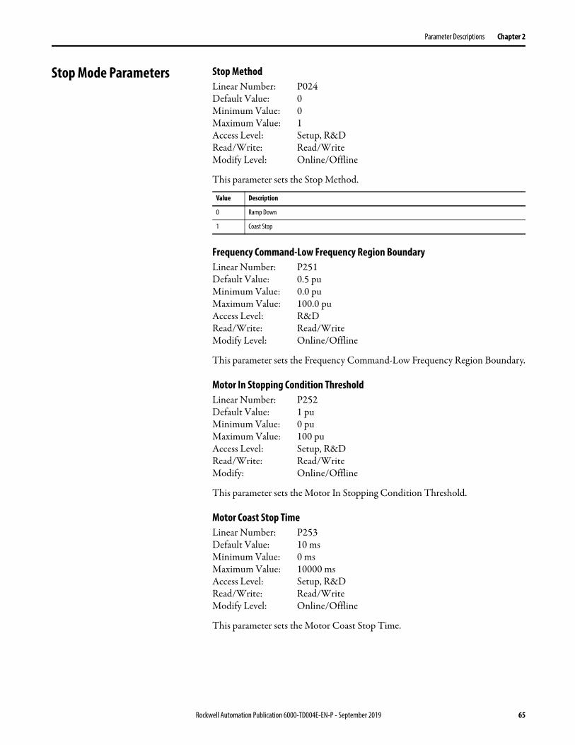
Parameter Descriptions Chapter 2
Stop Mode Parameters Stop MethodLinear Number: P024Default Value: 0Minimum Value: 0Maximum Value: 1Access Level: Setup, R&DRead/Write: Read/WriteModify Level: Online/Offline
This parameter sets the Stop Method.
Frequency Command-Low Frequency Region BoundaryLinear Number: P251Default Value: 0.5 pu Minimum Value: 0.0 puMaximum Value: 100.0 puAccess Level: R&DRead/Write: Read/WriteModify Level: Online/Offline
This parameter sets the Frequency Command-Low Frequency Region Boundary.
Motor In Stopping Condition ThresholdLinear Number: P252Default Value: 1 puMinimum Value: 0 puMaximum Value: 100 puAccess Level: Setup, R&DRead/Write: Read/WriteModify: Online/Offline
This parameter sets the Motor In Stopping Condition Threshold.
Motor Coast Stop TimeLinear Number: P253Default Value: 10 msMinimum Value: 0 msMaximum Value: 10000 msAccess Level: Setup, R&DRead/Write: Read/WriteModify Level: Online/Offline
This parameter sets the Motor Coast Stop Time.
Value Description
0 Ramp Down
1 Coast Stop
Rockwell Automation Publication 6000-TD004E-EN-P - September 2019 65

Chapter 2 Parameter Descriptions
Delayed Lockout Time of Stop OperationLinear Number: P270Default Value: 2000 msMinimum Value: 0 msMaximum Value: 5000 msAccess Level: R&DRead/Write: Read/WriteModify Level: Online/Offline
This parameter sets the Delayed Lockout Time of Stop Operation.
Motor Direction Control Parameters
Motor Rotation Direction Under Local ControlLinear Number: P008Default Value: 1Minimum Value: 0Maximum Value: 1Access Level: Setup, R&DRead/Write: Read/WriteModify Level: Offline only
This parameter sets the Motor Rotation Direction Under Local Control.
Motor Rotation Direction Command SelectionLinear Number: P009Default Value: 0Minimum Value: 0Maximum Value: 1Access Level: Setup, R&DRead/Write: Read/WriteModify Level: Offline only
This parameter sets the Motor Rotation Direction Command Selection. Either local control or DCS control can be selected as the command source.
Value Description
0 Reverse Motor rotates in the reverse direction.
1 Forward Motor rotates in the forward direction.
Value Description
0 Local Control Motor direction is determined by P008.
1 DCS Motor direction is determined by register K26.
66 Rockwell Automation Publication 6000-TD004E-EN-P - September 2019

Parameter Descriptions Chapter 2
Switch Frequency Setting Parameters
Switch Frequency Setting Enable CodeLinear Number: P087Default Value: 0Minimum Value: 0Maximum Value: 1Access Level: Setup, R&DRead/Write: Read/WriteModify Level: Offline only
This parameter is used to enable or disable the Switch Frequency Setting Code.
Switch Frequency SettingLinear Number: P088Default Value: 0Minimum Value: 0Maximum Value: 1Access Level: Setup, R&DRead/Write: Read/WriteModify Level: Offline only
This parameter is used to select the frequency value for Switch Frequency Setting.
VF Curve Setting Parameters Slip Compensation EnableLinear Number: P111Default Value: 0Minimum Value: 0Maximum Value: 1Access Level: R&DRead/Write: Read/WriteModify Level: Online/Offline
This parameter is used to enable or disable Slip Compensation.
Value Description
0 Disable Switch Frequency Setting Code
1 Enable Switch Frequency Setting Code
Value Description
0 600 Hz
1 1200 Hz
Value Description
0 Disable Slip Compensation
1 Enable Slip Compensation
Rockwell Automation Publication 6000-TD004E-EN-P - September 2019 67

Chapter 2 Parameter Descriptions
Flux DelayLinear Number: P271Default Value: 50 msMinimum Value: 0 msMaximum Value: 5000 msAccess Level: R&DRead/Write: Read/WriteModify Level: Online/Offline
This parameter sets the Flux Delay.
SVC Low Frequency Acceleration Time Enable Frequency Range Upper LimitLinear Number: P291Default Value: 10%Minimum Value: 0%Maximum Value: 100%Access Level: R&DRead/Write: Read/WriteModify Level: Online/Offline
This parameter sets the upper limit for SVC Low Frequency Acceleration Time Enable Frequency Range.
SVC Low Frequency Acceleration TimeLinear Number: P292Default Value: 5.0 sMinimum Value: 1.0 sMaximum Value: 3276.7 sAccess Level: R&DRead/Write: Read/WriteModify Level: Online/Offline
This parameter sets the SVC Low Frequency Acceleration Time.
SVC Flux Voltage Boost CoefficientLinear Number: P293Default Value: 300%Minimum Value: 0%Maximum Value: 500%Access Level: R&DRead/Write: Read/WriteModify Level: Online/Offline
This parameter sets the SVC Flux Voltage Boost Coefficient.
68 Rockwell Automation Publication 6000-TD004E-EN-P - September 2019
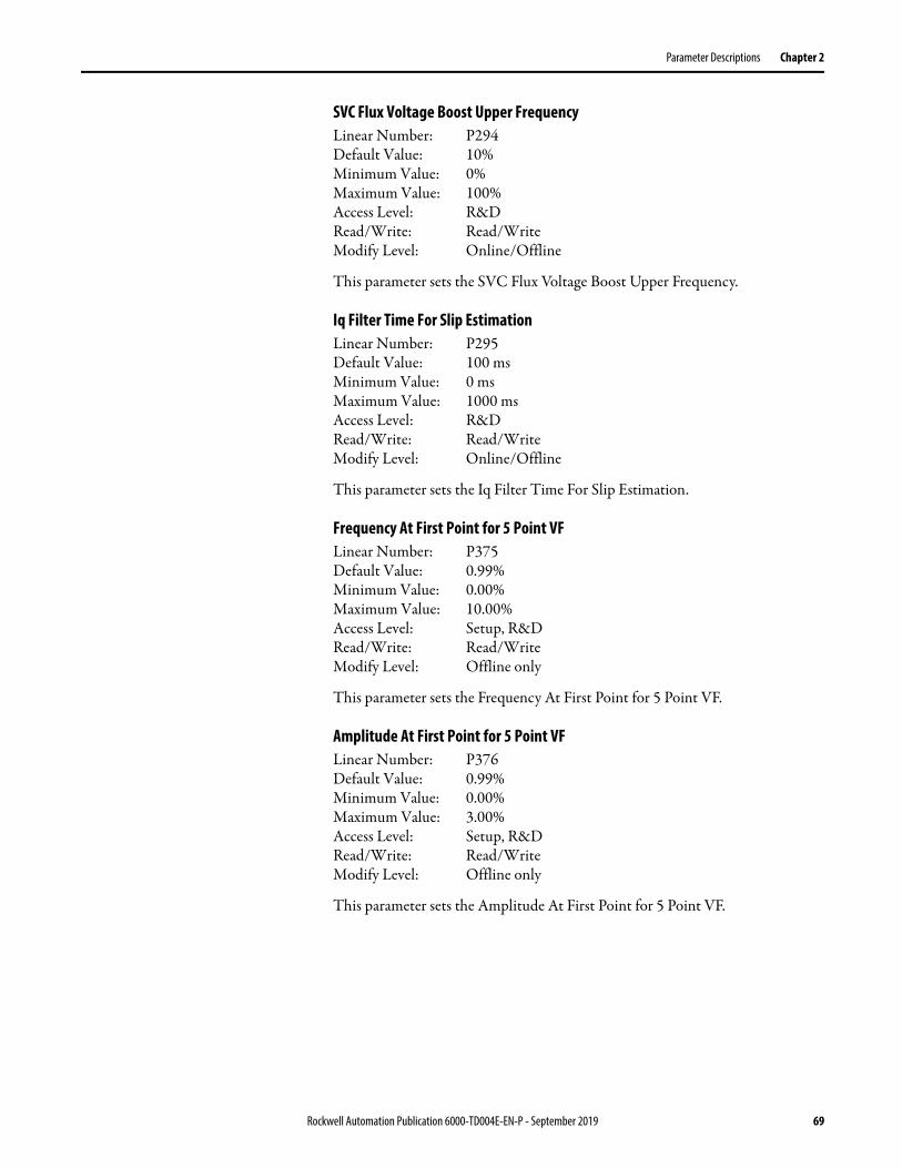
Parameter Descriptions Chapter 2
SVC Flux Voltage Boost Upper FrequencyLinear Number: P294Default Value: 10%Minimum Value: 0%Maximum Value: 100%Access Level: R&DRead/Write: Read/WriteModify Level: Online/Offline
This parameter sets the SVC Flux Voltage Boost Upper Frequency.
Iq Filter Time For Slip EstimationLinear Number: P295Default Value: 100 msMinimum Value: 0 msMaximum Value: 1000 msAccess Level: R&DRead/Write: Read/WriteModify Level: Online/Offline
This parameter sets the Iq Filter Time For Slip Estimation.
Frequency At First Point for 5 Point VFLinear Number: P375Default Value: 0.99%Minimum Value: 0.00%Maximum Value: 10.00%Access Level: Setup, R&DRead/Write: Read/WriteModify Level: Offline only
This parameter sets the Frequency At First Point for 5 Point VF.
Amplitude At First Point for 5 Point VFLinear Number: P376Default Value: 0.99%Minimum Value: 0.00%Maximum Value: 3.00%Access Level: Setup, R&DRead/Write: Read/WriteModify Level: Offline only
This parameter sets the Amplitude At First Point for 5 Point VF.
Rockwell Automation Publication 6000-TD004E-EN-P - September 2019 69
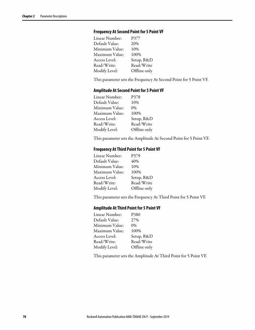
Chapter 2 Parameter Descriptions
Frequency At Second Point for 5 Point VFLinear Number: P377Default Value: 20%Minimum Value: 10%Maximum Value: 100%Access Level: Setup, R&DRead/Write: Read/WriteModify Level: Offline only
This parameter sets the Frequency At Second Point for 5 Point VF.
Amplitude At Second Point for 5 Point VFLinear Number: P378Default Value: 10%Minimum Value: 0%Maximum Value: 100%Access Level: Setup, R&DRead/Write: Read/WriteModify Level: Offline only
This parameter sets the Amplitude At Second Point for 5 Point VF.
Frequency At Third Point for 5 Point VFLinear Number: P379Default Value: 40%Minimum Value: 10%Maximum Value: 100%Access Level: Setup, R&DRead/Write: Read/WriteModify Level: Offline only
This parameter sets the Frequency At Third Point for 5 Point VF.
Amplitude At Third Point for 5 Point VFLinear Number: P380Default Value: 27%Minimum Value: 0%Maximum Value: 100%Access Level: Setup, R&DRead/Write: Read/WriteModify Level: Offline only
This parameter sets the Amplitude At Third Point for 5 Point VF.
70 Rockwell Automation Publication 6000-TD004E-EN-P - September 2019
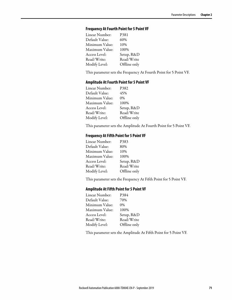
Parameter Descriptions Chapter 2
Frequency At Fourth Point for 5 Point VFLinear Number: P381Default Value: 60%Minimum Value: 10%Maximum Value: 100%Access Level: Setup, R&DRead/Write: Read/WriteModify Level: Offline only
This parameter sets the Frequency At Fourth Point for 5 Point VF.
Amplitude At Fourth Point for 5 Point VFLinear Number: P382Default Value: 45%Minimum Value: 0%Maximum Value: 100%Access Level: Setup, R&DRead/Write: Read/WriteModify Level: Offline only
This parameter sets the Amplitude At Fourth Point for 5 Point VF.
Frequency At Fifth Point for 5 Point VFLinear Number: P383Default Value: 80%Minimum Value: 10%Maximum Value: 100%Access Level: Setup, R&DRead/Write: Read/WriteModify Level: Offline only
This parameter sets the Frequency At Fifth Point for 5 Point VF.
Amplitude At Fifth Point for 5 Point VFLinear Number: P384Default Value: 70%Minimum Value: 0%Maximum Value: 100%Access Level: Setup, R&DRead/Write: Read/WriteModify Level: Offline only
This parameter sets the Amplitude At Fifth Point for 5 Point VF.
Rockwell Automation Publication 6000-TD004E-EN-P - September 2019 71
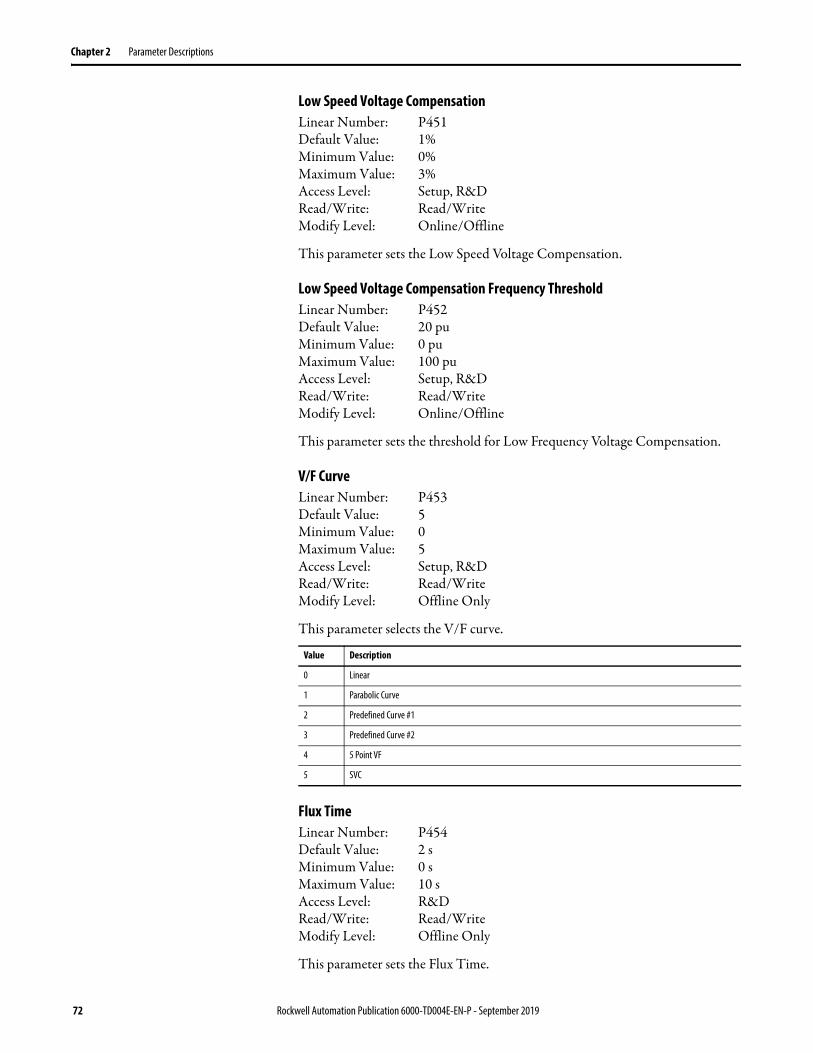
Chapter 2 Parameter Descriptions
Low Speed Voltage CompensationLinear Number: P451Default Value: 1%Minimum Value: 0%Maximum Value: 3%Access Level: Setup, R&DRead/Write: Read/WriteModify Level: Online/Offline
This parameter sets the Low Speed Voltage Compensation.
Low Speed Voltage Compensation Frequency ThresholdLinear Number: P452Default Value: 20 puMinimum Value: 0 puMaximum Value: 100 puAccess Level: Setup, R&DRead/Write: Read/WriteModify Level: Online/Offline
This parameter sets the threshold for Low Frequency Voltage Compensation.
V/F CurveLinear Number: P453Default Value: 5Minimum Value: 0Maximum Value: 5Access Level: Setup, R&DRead/Write: Read/WriteModify Level: Offline Only
This parameter selects the V/F curve.
Flux TimeLinear Number: P454Default Value: 2 sMinimum Value: 0 sMaximum Value: 10 sAccess Level: R&DRead/Write: Read/WriteModify Level: Offline Only
This parameter sets the Flux Time.
Value Description
0 Linear
1 Parabolic Curve
2 Predefined Curve #1
3 Predefined Curve #2
4 5 Point VF
5 SVC
72 Rockwell Automation Publication 6000-TD004E-EN-P - September 2019

Parameter Descriptions Chapter 2
Modulation IndexLinear Number: P455Default Value: 84.0% (2.3 kV), 87.6% (2.4 kV),
77.3% (3.0 kV), 85.0% (3.3 kV),83.8% (4.0 kV), 87.0% (4.16 kV),87.0% (6.0 kV), 81.0% (6.3 kV),85.0% (6.6 kV), 83.7% (6.9 kV),91% (10.0 kV)89% (11.0 kV)
Minimum Value: 0%Maximum Value: 110%Access Level: Setup, R&DRead/Write: Read/WriteModify Level: Online/Offline
This parameter sets the Modulation Index.
Motor Voltage Upper LimitLinear Number: P456Default Value: 84.0% (2.3 kV), 87.6% (2.4 kV),
77.3% (3.0 kV), 85.0% (3.3 kV),83.8% (4.0 kV), 87.0% (4.16 kV),87.0% (6.0 kV), 81.0% (6.3 kV),85.0% (6.6 kV), 83.7% (6.9 kV),91% (10.0 kV)89% (11.0 kV)
Minimum Value: 0%Maximum Value: 110%Access Level: Setup, R&DRead/Write: Read/WriteModify Level: Online/Offline
This parameter sets the Motor Voltage Upper Limit.
Coefficient ALinear Number: P458Default Value: 40%Minimum Value: 0%Maximum Value: 100%Access Level: R&DRead/Write: Read/WriteModify Level: Offline only
This parameter sets the Coefficient A.
Rockwell Automation Publication 6000-TD004E-EN-P - September 2019 73

Chapter 2 Parameter Descriptions
Analog Input Parameters Line Voltage Uab Scaling FactorLinear Number: P151Default Value: 153.0% (2.3 kV), 146.7% (2.4 kV),
175.9% (3.0 kV), 159.9% (3.3 kV),175.8% (4.0 kV), 169.0% (4.16 kV),146.5% (6.0 kV), 167.4% (6.3 kV),159.8% (6.6 kV), 152.8% (6.9 kV),158.1% (10.0 kV)143.7% (11.0 kV)
Minimum Value: 0.00%Maximum Value: 199.99%Access Level: Setup, R&DRead/Write: Read/WriteModify Level: Online/Offline
This parameter sets the Line Voltage Uab Scaling Factor.
Line Voltage Ubc Scaling FactorLinear Number: P152Default Value: 153.0% (2.3 kV), 146.7% (2.4 kV),
175.9% (3.0 kV), 159.9% (3.3 kV),175.8% (4.0 kV), 169.0% (4.16 kV),146.5% (6.0 kV), 167.4% (6.3 kV),159.8% (6.6 kV), 152.8% (6.9 kV),158.1% (10.0 kV)143.7% (11.0 kV)
Minimum Value: 0.00%Maximum Value: 199.99%Access Level: Setup, R&DRead/Write: Read/WriteModify Level: Online/Offline
This parameter sets the Line Voltage Ubc Scaling Factor.
Line Voltage Ung Scaling FactorLinear Number: P153Default Value: 100.00%Minimum Value: 0.00%Maximum Value: 199.99%Access Level: Setup, R&DRead/Write: Read/WriteModify Level: Online/Offline
This parameter sets the Line Voltage Ung Scaling Factor.
74 Rockwell Automation Publication 6000-TD004E-EN-P - September 2019
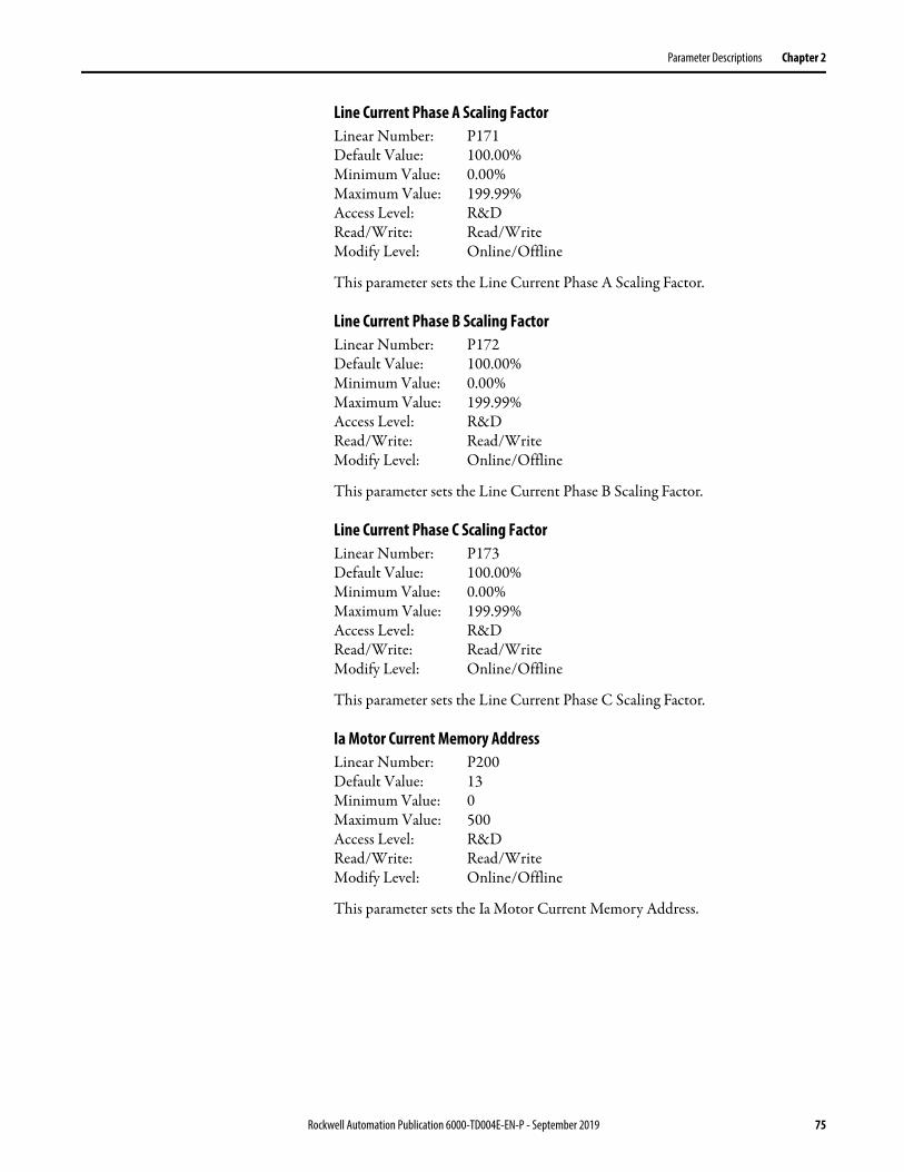
Parameter Descriptions Chapter 2
Line Current Phase A Scaling FactorLinear Number: P171Default Value: 100.00%Minimum Value: 0.00%Maximum Value: 199.99%Access Level: R&DRead/Write: Read/WriteModify Level: Online/Offline
This parameter sets the Line Current Phase A Scaling Factor.
Line Current Phase B Scaling FactorLinear Number: P172Default Value: 100.00%Minimum Value: 0.00%Maximum Value: 199.99%Access Level: R&DRead/Write: Read/WriteModify Level: Online/Offline
This parameter sets the Line Current Phase B Scaling Factor.
Line Current Phase C Scaling FactorLinear Number: P173Default Value: 100.00%Minimum Value: 0.00%Maximum Value: 199.99%Access Level: R&DRead/Write: Read/WriteModify Level: Online/Offline
This parameter sets the Line Current Phase C Scaling Factor.
Ia Motor Current Memory AddressLinear Number: P200Default Value: 13Minimum Value: 0Maximum Value: 500Access Level: R&DRead/Write: Read/WriteModify Level: Online/Offline
This parameter sets the Ia Motor Current Memory Address.
Rockwell Automation Publication 6000-TD004E-EN-P - September 2019 75

Chapter 2 Parameter Descriptions
Motor Ia Scaling FactorLinear Number: P201Default Value: 105.00%Minimum Value: 0.00%Maximum Value: 199.99%Access Level: R&DRead/Write: Read/WriteModify Level: Online/Offline
This parameter sets the Motor Ia Scaling Factor.
Ic Motor Current Memory AddressLinear Number: P202Default Value: 14Minimum Value: 0Maximum Value: 500Access Level: R&DRead/Write: Read/WriteModify Level: Online/Offline
This parameter sets the Ic Motor Current Memory Address.
Motor Ic Scaling FactorLinear Number: P203Default Value: 105.00%Minimum Value: 0.00%Maximum Value: 199.99%Access Level: R&DRead/Write: Read/WriteModify Leve: Online/Offline
This parameter sets the Motor Ic Scaling Factor.
Motor Uab Voltage AddressLinear Number: P204Default Value: 11Minimum Value: 0Maximum Value: 500Access Level: R&DRead/Write: Read/WriteModify Level: Online/Offline
This parameter sets the Motor Uab Voltage Address.
76 Rockwell Automation Publication 6000-TD004E-EN-P - September 2019

Parameter Descriptions Chapter 2
Motor Uab Voltage Scaling FactorLinear Number: P205Default Value: 153.0% (2.3 kV), 146.7% (2.4 kV),
175.9% (3.0 kV), 159.9% (3.3 kV),175.8% (4.0 kV), 169.0% (4.16 kV),146.5% (6.0 kV), 167.4% (6.3 kV),159.8% (6.6 kV), 152.8% (6.9 kV),158.1% (10.0 kV)143.7% (11.0 kV)
Minimum Value: 0.00%Maximum Value: 199.99%Access Level: Setup, R&DRead/Write: Read/WriteModify Level: Online/Offline
This parameter sets the Motor Uab Voltage Scaling Factor.
Motor Uac Voltage Scaling FactorLinear Number: P206Default Value: 153.0% (2.3 kV), 146.7% (2.4 kV),
175.9% (3.0 kV), 159.9% (3.3 kV),175.8% (4.0 kV), 169.0% (4.16 kV),146.5% (6.0 kV), 167.4% (6.3 kV),159.8% (6.6 kV), 152.8% (6.9 kV),158.1% (10.0 kV)143.7% (11.0 kV)
Minimum Value: 0.00%Maximum Value: 199.99%Access Level: Setup, R&DRead/Write: Read/WriteModify Level: Online/Offline
This parameter sets the Motor Uac Voltage Scaling Factor.
Digital Output Parameters Digital Output #0 Memory AddressLinear Number: P300Default Value: 99Minimum Value: 0Maximum Value: 500Access Level: R&DRead/Write: Read/WriteModify Level: Online/Offline
This parameter sets the memory address for digital output #0.
Rockwell Automation Publication 6000-TD004E-EN-P - September 2019 77
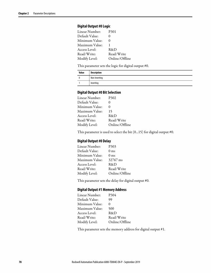
Chapter 2 Parameter Descriptions
Digital Output #0 LogicLinear Number: P301Default Value: 0Minimum Value: 0Maximum Value: 1Access Level: R&DRead/Write: Read/WriteModify Level: Online/Offline
This parameter sets the logic for digital output #0.
Digital Output #0 Bit SelectionLinear Number: P302Default Value: 0Minimum Value: 0Maximum Value: 15Access Level: R&DRead/Write: Read/WriteModify Level: Online/Offline
This parameter is used to select the bit (0...15) for digital output #0.
Digital Output #0 DelayLinear Number: P303Default Value: 0 msMinimum Value: 0 msMaximum Value: 32767 msAccess Level: R&DRead/Write: Read/WriteModify Level: Online/Offline
This parameter sets the delay for digital output #0.
Digital Output #1 Memory AddressLinear Number: P304Default Value: 99Minimum Value: 0Maximum Value: 500Access Level: R&DRead/Write: Read/WriteModify Level: Online/Offline
This parameter sets the memory address for digital output #1.
Value Description
0 Non-Inverting
1 Inverting
78 Rockwell Automation Publication 6000-TD004E-EN-P - September 2019
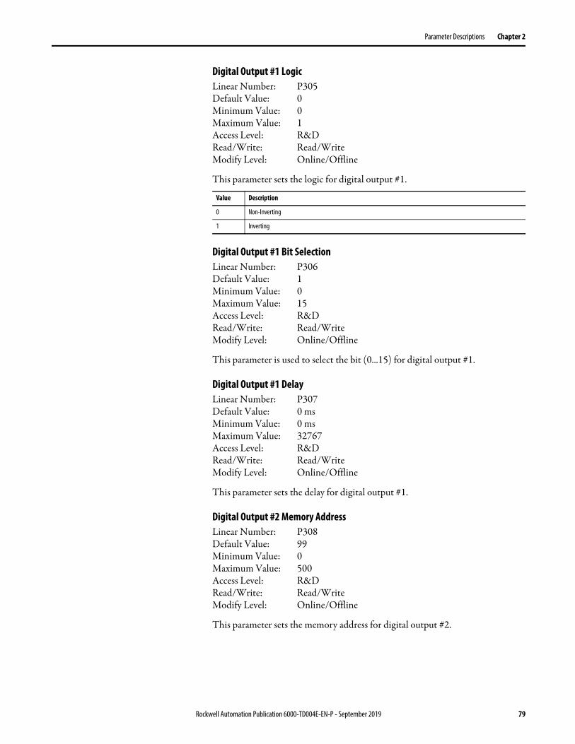
Parameter Descriptions Chapter 2
Digital Output #1 LogicLinear Number: P305Default Value: 0Minimum Value: 0Maximum Value: 1Access Level: R&DRead/Write: Read/WriteModify Level: Online/Offline
This parameter sets the logic for digital output #1.
Digital Output #1 Bit SelectionLinear Number: P306Default Value: 1Minimum Value: 0Maximum Value: 15Access Level: R&DRead/Write: Read/WriteModify Level: Online/Offline
This parameter is used to select the bit (0...15) for digital output #1.
Digital Output #1 DelayLinear Number: P307Default Value: 0 msMinimum Value: 0 msMaximum Value: 32767Access Level: R&DRead/Write: Read/WriteModify Level: Online/Offline
This parameter sets the delay for digital output #1.
Digital Output #2 Memory AddressLinear Number: P308Default Value: 99Minimum Value: 0Maximum Value: 500Access Level: R&DRead/Write: Read/WriteModify Level: Online/Offline
This parameter sets the memory address for digital output #2.
Value Description
0 Non-Inverting
1 Inverting
Rockwell Automation Publication 6000-TD004E-EN-P - September 2019 79

Chapter 2 Parameter Descriptions
Digital Output #2 LogicLinear Number: P309Default Value: 0Minimum Value: 0Maximum Value: 1Access Level: R&DRead/Write: Read/WriteModify Level: Online/Offline
This parameter sets the logic for digital output #2.
Digital Output #2 Bit SelectionLinear Number: P310Default Value: 2Minimum Value: 0Maximum Value: 15Access Level: R&DRead/Write: Read/WriteModify Level: Online/Offline
This parameter is used to select the bit (0...15) for digital output #2.
Digital Output #2 DelayLinear Number: P311Default Value: 0 msMinimum Value: 0 msMaximum Value: 32767 msAccess Level: R&DRead/Write: Read/WriteModify Level: Online/Offline
This parameter sets the delay for digital output #2.
Digital Output #3 Memory AddressLinear Number: P312Default Value: 99Minimum Value: 0Maximum Value: 500Access Level: R&DRead/Write: Read/WriteModify Level: Online/Offline
This parameter sets the memory address for digital output #3.
Value Description
0 Non-Inverting
1 Inverting
80 Rockwell Automation Publication 6000-TD004E-EN-P - September 2019

Parameter Descriptions Chapter 2
Digital Output #3 LogicLinear Number: P313Default Value: 0Minimum Value: 0Maximum Value: 1Access Level: R&DRead/Write: Read/WriteModify Level: Online/Offline
This parameter sets the logic for digital output #3.
Digital Output #3 Bit SelectionLinear Number: P314Default Value: 3Minimum Value: 0Maximum Value: 15Access Level: R&DRead/Write: Read/WriteModify Level: Online/Offline
This parameter is used to select the bit (0...15) for digital output #3.
Digital Output #3 DelayLinear Number: P315Default Value: 0 msMinimum Value: 0 msMaximum Value: 32767 msAccess Level: R&DRead/Write: Read/WriteModify Level: Online/Offline
This parameter sets the delay for digital output #3.
Digital Output #4 Memory AddressLinear Number: P316Default Value: 99Minimum Value: 0Maximum Value: 500Access Level: R&DRead/Write: Read/WriteModify Level: Online/Offline
This parameter sets the memory address for digital output #4.
Value Description
0 Non-Inverting
1 Inverting
Rockwell Automation Publication 6000-TD004E-EN-P - September 2019 81

Chapter 2 Parameter Descriptions
Digital Output #4 LogicLinear Number: P317Default Value: 0Minimum Value: 0Maximum Value: 1Access Level: R&DRead/Write: Read/WriteModify Level: Online/Offline
This parameter sets the logic for digital output #4.
Digital Output #4 Bit SelectionLinear Number: P318Default Value: 4Minimum Value: 0Maximum Value: 15Access Level: R&DRead/Write: Read/WriteModify Level: Online/Offline
This parameter is used to select the bit (0...15) for digital output #4.
Digital Output #4 DelayLinear Number: P319Default Value: 0 msMinimum Value: 0 msMaximum Value: 32767 msAccess Level: R&DRead/Write: Read/WriteModify Level: Online/Offline
This parameter sets the delay for digital output #4.
Digital Output #5 Memory AddressLinear Number: P320Default Value: 99Minimum Value: 0Maximum Value: 500Access Level: R&DRead/Write: Read/WriteModify Level: Online/Offline
This parameter sets the memory address for digital output #5.
Value Description
0 Non-Inverting
1 Inverting
82 Rockwell Automation Publication 6000-TD004E-EN-P - September 2019

Parameter Descriptions Chapter 2
Digital Output #5 LogicLinear Number: P321Default Value: 0Minimum Value: 0Maximum Value: 1Access Level: R&DRead/Write: Read/WriteModify Level: Online/Offline
This parameter sets the logic for digital output #5.
Digital Output #5 Bit SelectionLinear Number: P322Default Value: 5Minimum Value: 0Maximum Value: 15Access Level: R&DRead/Write: Read/WriteModify Level: Online/Offline
This parameter is used to select the bit (0...15) for digital output #5.
Digital Output #5 DelayLinear Number: P323Default Value: 0 msMinimum Value: 0 msMaximum Value: 32767 msAccess Level: R&DRead/Write: Read/WriteModify Level: Online/Offline
This parameter sets the delay for digital output #5.
Digital Output #6 Memory AddressLinear Number: P324Default Value: 99Minimum Value: 0Maximum Value: 500Access Level: R&DRead/Write: Read/WriteModify Level: Online/Offline
This parameter sets the memory address for digital output #6.
Value Description
0 Non-Inverting
1 Inverting
Rockwell Automation Publication 6000-TD004E-EN-P - September 2019 83
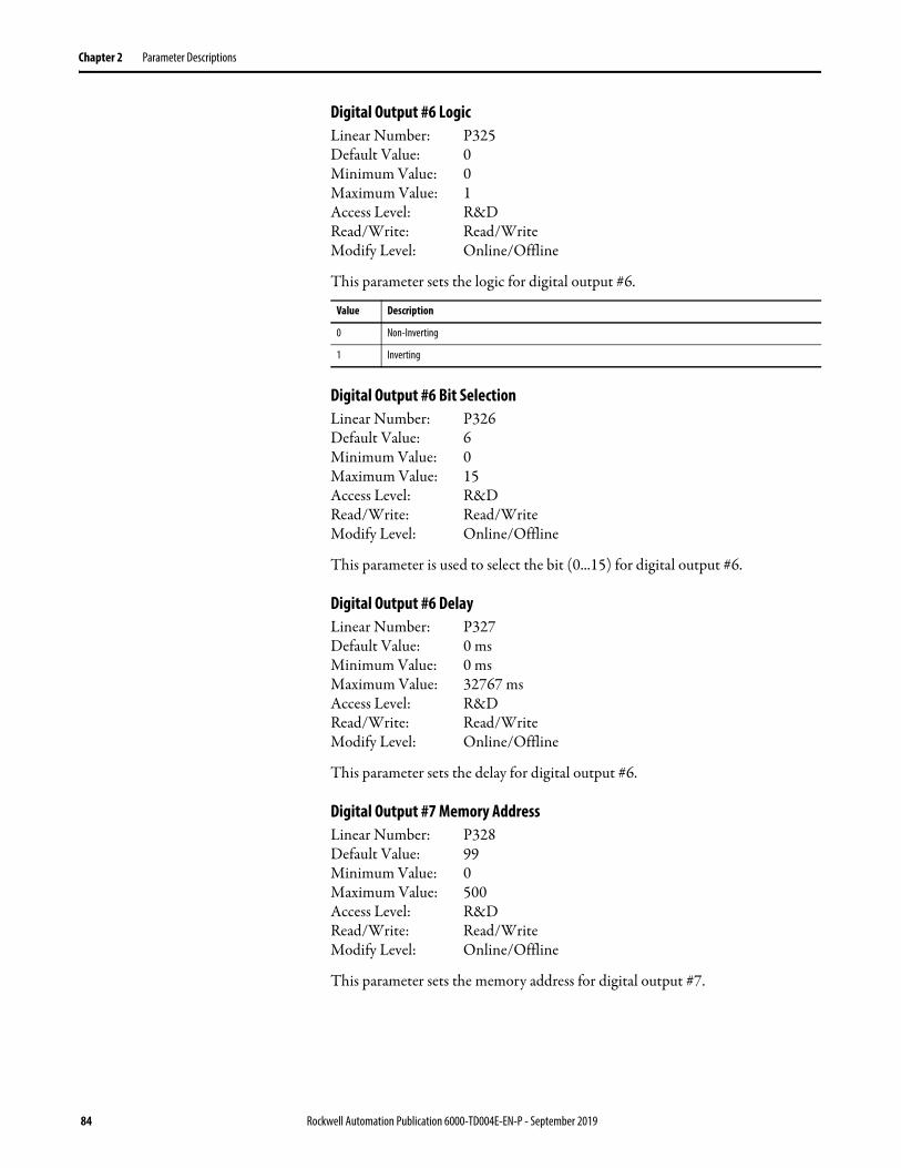
Chapter 2 Parameter Descriptions
Digital Output #6 LogicLinear Number: P325Default Value: 0Minimum Value: 0Maximum Value: 1Access Level: R&DRead/Write: Read/WriteModify Level: Online/Offline
This parameter sets the logic for digital output #6.
Digital Output #6 Bit SelectionLinear Number: P326Default Value: 6Minimum Value: 0Maximum Value: 15Access Level: R&DRead/Write: Read/WriteModify Level: Online/Offline
This parameter is used to select the bit (0...15) for digital output #6.
Digital Output #6 DelayLinear Number: P327Default Value: 0 msMinimum Value: 0 msMaximum Value: 32767 msAccess Level: R&DRead/Write: Read/WriteModify Level: Online/Offline
This parameter sets the delay for digital output #6.
Digital Output #7 Memory AddressLinear Number: P328Default Value: 99Minimum Value: 0Maximum Value: 500Access Level: R&DRead/Write: Read/WriteModify Level: Online/Offline
This parameter sets the memory address for digital output #7.
Value Description
0 Non-Inverting
1 Inverting
84 Rockwell Automation Publication 6000-TD004E-EN-P - September 2019
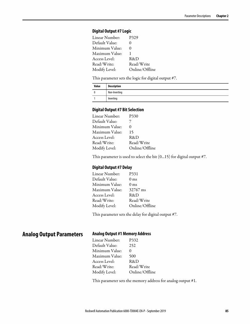
Parameter Descriptions Chapter 2
Digital Output #7 LogicLinear Number: P329Default Value: 0Minimum Value: 0Maximum Value: 1Access Level: R&DRead/Write: Read/WriteModify Level: Online/Offline
This parameter sets the logic for digital output #7.
Digital Output #7 Bit SelectionLinear Number: P330Default Value: 7Minimum Value: 0Maximum Value: 15Access Level: R&DRead/Write: Read/WriteModify Level: Online/Offline
This parameter is used to select the bit (0...15) for digital output #7.
Digital Output #7 DelayLinear Number: P331Default Value: 0 msMinimum Value: 0 msMaximum Value: 32767 msAccess Level: R&DRead/Write: Read/WriteModify Level: Online/Offline
This parameter sets the delay for digital output #7.
Analog Output Parameters Analog Output #1 Memory AddressLinear Number: P332Default Value: 252Minimum Value: 0Maximum Value: 500Access Level: R&DRead/Write: Read/WriteModify Level: Online/Offline
This parameter sets the memory address for analog output #1.
Value Description
0 Non-Inverting
1 Inverting
Rockwell Automation Publication 6000-TD004E-EN-P - September 2019 85
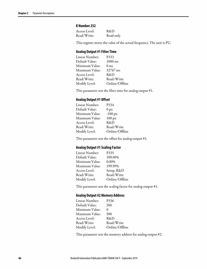
Chapter 2 Parameter Descriptions
K Number 252Access Level: R&DRead/Write: Read only
This register stores the value of the actual frequency. The unit is PU.
Analog Output #1 Filter TimeLinear Number: P333Default Value: 1000 msMinimum Value: 0 msMaximum Value: 32767 msAccess Level: R&DRead/Write: Read/WriteModify Level: Online/Offline
This parameter sets the filter time for analog output #1.
Analog Output #1 OffsetLinear Number: P334Default Value: 0 puMinimum Value: -100 puMaximum Value: 100 puAccess Level: R&DRead/Write: Read/WriteModify Level: Online/Offline
This parameter sets the offset for analog output #1.
Analog Output #1 Scaling FactorLinear Number: P335Default Value: 100.00%Minimum Value: 0.00%Maximum Value: 199.99%Access Level: Setup, R&DRead/Write: Read/WriteModify Level: Online/Offline
This parameter sets the scaling factor for analog output #1.
Analog Output #2 Memory AddressLinear Number: P336Default Value: 206Minimum Value: 0Maximum Value: 500Access Level: R&DRead/Write: Read/WriteModify Level: Online/Offline
This parameter sets the memory address for analog output #2.
86 Rockwell Automation Publication 6000-TD004E-EN-P - September 2019

Parameter Descriptions Chapter 2
Analog Output #2 Filter TimeLinear Number: P337Default Value: 1000 msMinimum Value: 0 msMaximum Value: 32767 msAccess Level: R&DRead/Write: Read/WriteModify Level: Online/Offline
This parameter sets the filter time for analog output #2.
Analog Output #2 OffsetLinear Number: P338Default Value: 0 puMinimum Value: -100 puMaximum Value: 100 puAccess Level: R&DRead/Write: Read/WriteModify Level: Online/Offline
This parameter sets the offset for analog output #2.
Analog Output #2 Scaling FactorLinear Number: P339Default Value: 100.00%Minimum Value: 0.00%Maximum Value: 199.99%Access Level: Setup, R&DRead/Write: Read/WriteModify Level: Online/Offline
This parameter sets the scaling factor for analog output #2.
Analog Output #3 Memory AddressLinear Number: P340Default Value: 0Minimum Value: 0Maximum Value: 500Access Level: R&DRead/Write: Read/WriteModify Level: Online/Offline
This parameter sets the memory address for analog output #3.
Rockwell Automation Publication 6000-TD004E-EN-P - September 2019 87
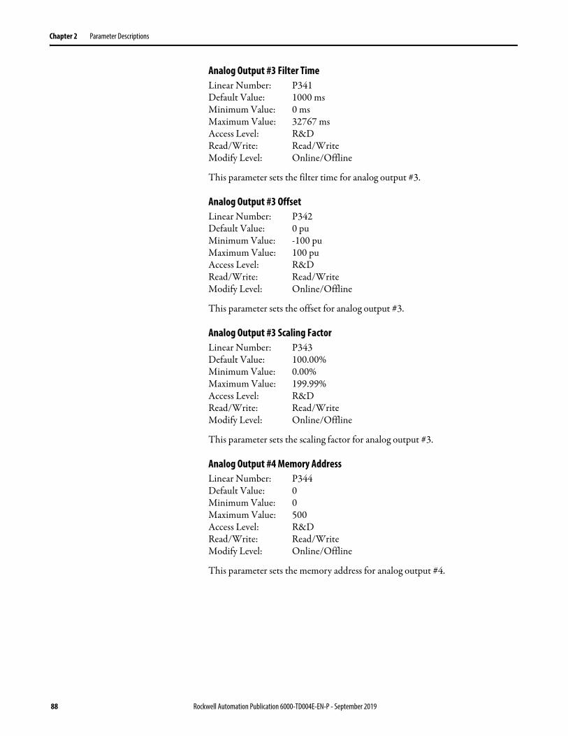
Chapter 2 Parameter Descriptions
Analog Output #3 Filter TimeLinear Number: P341Default Value: 1000 msMinimum Value: 0 msMaximum Value: 32767 msAccess Level: R&DRead/Write: Read/WriteModify Level: Online/Offline
This parameter sets the filter time for analog output #3.
Analog Output #3 OffsetLinear Number: P342Default Value: 0 puMinimum Value: -100 puMaximum Value: 100 puAccess Level: R&DRead/Write: Read/WriteModify Level: Online/Offline
This parameter sets the offset for analog output #3.
Analog Output #3 Scaling FactorLinear Number: P343Default Value: 100.00%Minimum Value: 0.00%Maximum Value: 199.99%Access Level: R&DRead/Write: Read/WriteModify Level: Online/Offline
This parameter sets the scaling factor for analog output #3.
Analog Output #4 Memory AddressLinear Number: P344Default Value: 0Minimum Value: 0Maximum Value: 500Access Level: R&DRead/Write: Read/WriteModify Level: Online/Offline
This parameter sets the memory address for analog output #4.
88 Rockwell Automation Publication 6000-TD004E-EN-P - September 2019
Parameter Descriptions Chapter 2
Analog Output #4 Filter TimeLinear Number: P345Default Value: 1000 msMinimum Value: 0 msMaximum Value: 32767 msAccess Level: R&DRead/Write: Read/WriteModify Level: Online/Offline
This parameter sets the filter time for analog output #4.
Analog Output #4 OffsetLinear Number: P346Default Value: 0 puMinimum Value: -100 puMaximum Value: 100 puAccess Level: R&DRead/Write: Read/WriteModify Level: Online/Offline
This parameter sets the offset for analog output #4.
Analog Output #4 Scaling FactorLinear Number: P347Default Value: 100.00%Minimum Value: 0.00%Maximum Value: 199.99%Access Level: R&DRead/Write: Read/WriteModify Level: Online/Offline
This parameter sets the scaling factor for analog output #4.
Version Control Parameters Version Compatibility EnableLinear Number: P470Default Value: 1Minimum Value: 0Maximum Value: 1Access Level: R&DRead/Write: Read/WriteModify Level: Offline only
This parameter is used to enable or disable the version control feature. The value will be saved in register K495
Value Description
0 Disable Version Control
1 Enable Version Control
Rockwell Automation Publication 6000-TD004E-EN-P - September 2019 89

Chapter 2 Parameter Descriptions
Fan Control Parameters Fan Control ModeLinear Number: P094Default Value: 0Minimum Value: 0Maximum Value: 2Access Level: Setup, R&DRead/Write: Read/WriteModify Level: Offline only
This parameter is used to select the fan control mode.
Fan Control Group #1 Fan NumberLinear Number: P095Default Value: 0Minimum Value: 0Maximum Value: 10Access Level: Setup, R&DRead/Write: Read/WriteModify Level: Offline only
This parameter sets the number of fans in transformer cabinet #1.
Fan Control Group #2 Fan NumberLinear Number: P096Default Value: 0Minimum Value: 0Maximum Value: 10Access Level: Setup, R&DRead/Write: Read/WriteModify Level: Offline only
This parameter sets the number of fans in transformer cabinet #2.
Fan Control Group #3 Fan NumberLinear Number: P097Default Value: 0Minimum Value: 0Maximum Value: 100Access Level: Setup, R&DRead/Write: Read/WriteModify Level: Offline only
This parameter sets the number of fans in the power cell cabinet.
Value Description
0 Non-redundant fan mode
1 One fan as redundant fan mode
2 All fans in cycle mode
90 Rockwell Automation Publication 6000-TD004E-EN-P - September 2019
Parameter Descriptions Chapter 2
Fan Control Group #4 Fan NumberLinear Number: P098Default Value: 0Minimum Value: 0Maximum Value: 100Access Level: Setup, R&DRead/Write: Read/WriteModify Level: Offline only
This parameter sets the number of fans in the filter cabinet.
Fan Control Main Cooling Fan Cycle Time Linear Number: P099Default Value: 720 hrMinimum Value: 0 hrMaximum Value: 14400 hrAccess Level: Setup, R&DRead/Write: Read/WriteModify Level: Online/Offline
This parameter sets the work time of the main cooling fan.
Fan Control Redundant Fan Working TimeLinear Number: P100Default Value: 1 hrMinimum Value: 0 hrMaximum Value: 14400 hrAccess Level: Setup, R&DRead/Write: Read/WriteModify Level: Online/Offline
This parameter sets the work time of the redundant fan.
Fan Control Fan Feedback DelayLinear Number: P101Default Value: 200Minimum Value: 0Maximum Value: 1000Access Level: Setup, R&DRead/Write: Read/WriteModify Level: Online/Offline
This parameter sets the feedback delay of the fan status. The unit is 100 ms.
Rockwell Automation Publication 6000-TD004E-EN-P - September 2019 91
Chapter 2 Parameter Descriptions
Fan Control Fan Stop DelayLinear Number: P102Default Value: 0 minMinimum Value: 0 minMaximum Value: 10 minAccess Level: Setup, R&DRead/Write: Read/WriteModify Level: Online/Offline
This parameter sets the fan stop delay time when the drive is stopping normally.
Fan Control Transformer Cabinet Fan Quantity Upper LimitLinear Number: P106Default Value: 10Minimum Value: 0Maximum Value: 16Access Level: Setup, R&DRead/Write: Read/WriteModify Level: Online/Offline
This parameter sets the upper limit for the Fan Control Transformer Cabinet Fan Quantity.
Fan Control TX Cabinet Fan Fault Trip DelayLinear Number: P116Default Value: 30 minMinimum Value: 1 minMaximum Value: 60 minAccess Level: Setup, R&DRead/Write: Read/WriteModify Level: Online/Offline
This parameter sets the delay trip time when the TX cabinet fan has a fault.
Fan Control Filter Cabinet Fan Fault Trip DelayLinear Number: P117Default Value: 30 minMinimum Value: 1 minMaximum Value: 60 minAccess Level: Setup, R&DRead/Write: Read/WriteModify Level: Online/Offline
This parameter sets the delay trip time when the filter cabinet fan has a fault.
92 Rockwell Automation Publication 6000-TD004E-EN-P - September 2019
Parameter Descriptions Chapter 2
Drive Start DelayLinear Number: P186Default Value: 0 msMinimum Value: 0 msMaximum Value: 32767 msAccess Level: R&DRead/Write: Read/WriteModify Level: Online/Offline
This parameter sets the delay before the drive starts. This is necessary to allow the cooling fans to start before the drive, to ensure there is enough cooling.
Pre-charge Control Parameters
Pre-charge EnableLinear Number: P103Default Value: 0Minimum Value: 0Maximum Value: 1Access Level: Setup, R&DRead/Write: Read/WriteModify Level: Offline only
This parameter is used to enable or disable the pre-charge function.
Pre-charge Feedback DelayLinear Number: P104Default Value: 20Minimum Value: 0Maximum Value: 100Access Level: R&DRead/Write: Read/WriteModify Level: Online/Offline
This parameter sets the delay for the pre-charge feedback (100 ms). When the control box sends a command to the pre-charge cabinet, the pre-charge cabinet receives it and returns a feedback signal. If the control box does not receive the feedback signal within a certain time, the system will be locked.
Value Description
0 Disable pre-charge
1 Enable pre-charge
Rockwell Automation Publication 6000-TD004E-EN-P - September 2019 93
Chapter 2 Parameter Descriptions
Pre-charge DC Bus Threshold Linear Number: P105Default Value: 80%Minimum Value: 0%Maximum Value: 100%Access Level: R&DRead/Write: Read/WriteModify Level: Online/Offline
This parameter sets the threshold for the pre-charge DC bus voltage. The duration of the pre-charge is the time taken for the DC bus voltage to reach the set threshold. When DC bus voltage reaches this threshold is one of the conditions to determine that pre-charging is completed.
Pre-charge Max TimeLinear Number: P118Default Value: 6 sMinimum Value: 2 sMaximum Value: 20 sAccess Level: Setup, R&DRead/Write: Read/WriteModify Level: Online/Offline
This parameter sets the maximum time for pre-charging. If the pre-charge duration exceeds this time, it is considered pre-charge process overtime.
Pre-charge Min Repeat IntervalLinear Number: P119Default Value: 5 minMinimum Value: 5 minMaximum Value: 60 minAccess Level: Setup, R&DRead/Write: Read/WriteModify Level: Online/Offline
This parameter sets the minimum repeat interval time for pre-charging. After a pre-charge is complete, the timer starts. If another pre-charge occurs within the set time, it is considered pre-charge overtime.
Pre-charge Primary Voltage ThresholdLinear Number: P120Default Value: 80%Minimum Value: 0%Maximum Value: 100%Access Level: R&DRead/Write: Read/WriteModify Level: Online/Offline
This parameter sets the threshold for the pre-charge primary voltage. When line side voltage reaches this threshold is one of the conditions to determine that pre-charging is completed.
94 Rockwell Automation Publication 6000-TD004E-EN-P - September 2019
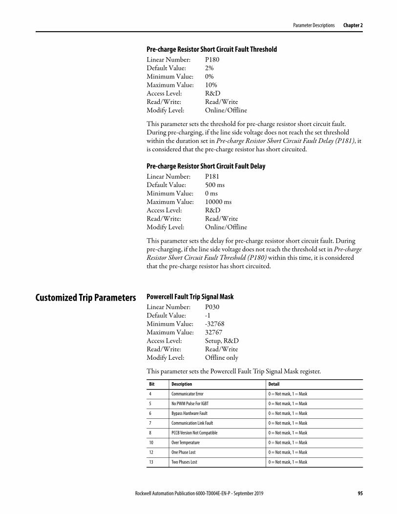
Parameter Descriptions Chapter 2
Pre-charge Resistor Short Circuit Fault ThresholdLinear Number: P180Default Value: 2%Minimum Value: 0%Maximum Value: 10%Access Level: R&DRead/Write: Read/WriteModify Level: Online/Offline
This parameter sets the threshold for pre-charge resistor short circuit fault. During pre-charging, if the line side voltage does not reach the set threshold within the duration set in Pre-charge Resistor Short Circuit Fault Delay (P181), it is considered that the pre-charge resistor has short circuited.
Pre-charge Resistor Short Circuit Fault DelayLinear Number: P181Default Value: 500 msMinimum Value: 0 msMaximum Value: 10000 msAccess Level: R&DRead/Write: Read/WriteModify Level: Online/Offline
This parameter sets the delay for pre-charge resistor short circuit fault. During pre-charging, if the line side voltage does not reach the threshold set in Pre-charge Resistor Short Circuit Fault Threshold (P180) within this time, it is considered that the pre-charge resistor has short circuited.
Customized Trip Parameters Powercell Fault Trip Signal MaskLinear Number: P030Default Value: -1Minimum Value: -32768Maximum Value: 32767Access Level: Setup, R&DRead/Write: Read/WriteModify Level: Offline only
This parameter sets the Powercell Fault Trip Signal Mask register.
Bit Description Detail
4 Communicator Error 0 = Not mask, 1 = Mask
5 No PWM Pulse For IGBT 0 = Not mask, 1 = Mask
6 Bypass Hardware Fault 0 = Not mask, 1 = Mask
7 Communication Link Fault 0 = Not mask, 1 = Mask
8 PCCB Version Not Compatible 0 = Not mask, 1 = Mask
10 Over Temperature 0 = Not mask, 1 = Mask
12 One Phase Lost 0 = Not mask, 1 = Mask
13 Two Phases Lost 0 = Not mask, 1 = Mask
Rockwell Automation Publication 6000-TD004E-EN-P - September 2019 95

Chapter 2 Parameter Descriptions
System Fault Trip Signal MaskLinear Number: P031Default Value: -1Minimum Value: -32768Maximum Value: 32767Access Level: Setup, R&DRead/Write: Read/WriteModify Level: Offline only
This parameter sets the System Fault Trip Signal Mask register.
System Fault B Trip Signal MaskLinear Number: P145Default Value: -1Minimum Value: -32768Maximum Value: 32767Access Level: Setup, R&DRead/Write: Read/WriteModify Level: Offline only
This parameter sets the System Fault Trip B Signal Mask register.
Over Speed Parameters Rated Output FrequencyLinear Number: P460Default Value: 50Minimum Value: 0Maximum Value: 75pAccess Level: Setup, R&DRead/Write: Read/WriteModify Level: Offline only
This parameter sets the Rated Output Frequency.
Bit Description Detail
2 Fan Failure in Fan Group #1 0 = Not mask, 1 = Mask
3 Output Over Voltage 0 = Not mask, 1 = Mask
4 Abnormal Output Voltage 0 = Not mask, 1 = Mask
6 Over Speed Fault 0 = Not mask, 1 = Mask
7 Motor Stalled 0 = Not mask, 1 = Mask
9 Output phase Over Current 0 = Not mask, 1 = Mask
10 VFD Over Current 1 0 = Not mask, 1 = Mask
Bit Description Detail
6 Fan Failure in Fan Group #4 0 = Not mask, 1 = Mask
9 DC Bus Under Voltage Fault 0 = Not mask, 1 = Mask
96 Rockwell Automation Publication 6000-TD004E-EN-P - September 2019

Parameter Descriptions Chapter 2
Maximum Output FrequencyLinear Number: P466Default Value: 50Minimum Value: 0Maximum Value: 75Access Level: Setup, R&DRead/Write: Read/WriteModify Level: Offline only
This parameter sets the Maximum Output Frequency.
Over Speed EnableLinear Number: P467Default Value: 0Minimum Value: 0Maximum Value: 1Access Level: Setup, R&DRead/Write: Read/WriteModify Level: Offline only
This parameter is used to enable or disable the Over Speed function.
Voltage Sag Parameters Derating Function EnableLinear Number: P182Default Value: 1Minimum Value: 0Maximum Value: 1Access Level: R&DRead/Write: Read/WriteModify Level: Offline only
This parameter is used to enable or disable the derating function.
Value Description
0 Disable Over Speed
1 Enable Over Speed
Value Description
0 Disable Derating Function
1 Enable Derating Function
Rockwell Automation Publication 6000-TD004E-EN-P - September 2019 97
Chapter 2 Parameter Descriptions
Voltage Lower Threshold For Drive Derating Per Cooling Fan Input Voltage DropLinear Number: P183Default Value: 70Minimum Value: 0Maximum Value: 100Access Level: R&DRead/Write: Read/WriteModify Level: Online/Offline
This parameter sets the lower voltage threshold for Drive Derating Per Cooling Fan Input Voltage Drop. If the cooling fan input voltage is lower than this setting, the maximum output current is limited to the value set in Drive Output Current Upper Limitation Per Cooling Fan Input Voltage Drop (P185).
Voltage Upper Threshold For Drive Derating Per Cooling Fan Input Voltage DropLinear Number: P184Default Value: 75Minimum Value: 0Maximum Value: 100Access Level: R&DRead/Write: Read/WriteModify Level: Online/Offline
This parameter sets the upper voltage threshold for Drive Derating Per Cooling Fan Input Voltage Drop. If the cooling fan input voltage is higher than this setting, the drive will exit the de-rate operation. This parameter and Voltage Lower Threshold For Drive Derating Per Cooling Fan Input Voltage Drop (P184) are the upper and lower limits of the hysteresis controller for drive de-rate caused by the cooling fan input voltage drop. The maximum output current is limited to the value set in Drive Output Current Upper Limitation Per Cooling Fan Input Voltage Drop (P185).
Drive Output Current Upper Limitation Per Cooling Fan Input Voltage DropLinear Number: P185Default Value: 76Minimum Value: 0Maximum Value: 100Access Level: R&DRead/Write: Read/WriteModify Level: Online/Offline
This parameter sets the upper limit for drive output current during de-rating caused by cooling fan input voltage drop.
98 Rockwell Automation Publication 6000-TD004E-EN-P - September 2019

Parameter Descriptions Chapter 2
Flux Control Signal Filter TimeLinear Number: P268Default Value: 999.97 msMinimum Value: 0.00 msMaximum Value: 13663.80 msAccess Level: R&DRead/Write: Read/WriteModify Level: Online/Offline
This parameter sets the Flux Control Signal Filter Time.
System Derating Control Signal Filter TimeLinear Number: P269Default Value: 999.97 msMinimum Value: 0.00 msMaximum Value: 13499.96 msAccess Level: R&DRead/Write: Read/WriteModify Level: Online/Offline
This parameter sets the System Derating Control Signal Filter Time.
Flux Control Compensation GainLinear Number: P272Default Value: 25%Minimum Value: 0%Maximum Value: 100%Access Level: R&DRead/Write: Read/WriteModify Level: Online/Offline
This parameter sets the Flux Control Compensation Gain. Assume “Verr” is the difference between the set output voltage and actual output voltage. When the flux control function is trigged, the deceleration time will be extended if this parameter is less than “Verr”.
Flux Control Regulation Control EnableLinear Number: P273Default Value: 1Minimum Value: 0Maximum Value: 1Access Level: R&DRead/Write: Read/WriteModify Level: Online/Offline
This parameter is used to enable or disable the Flux Control Regulation Control function.
Value Description
0 Disable Flux Control Regulation Control
1 Enable Flux Control Regulation Control
Rockwell Automation Publication 6000-TD004E-EN-P - September 2019 99
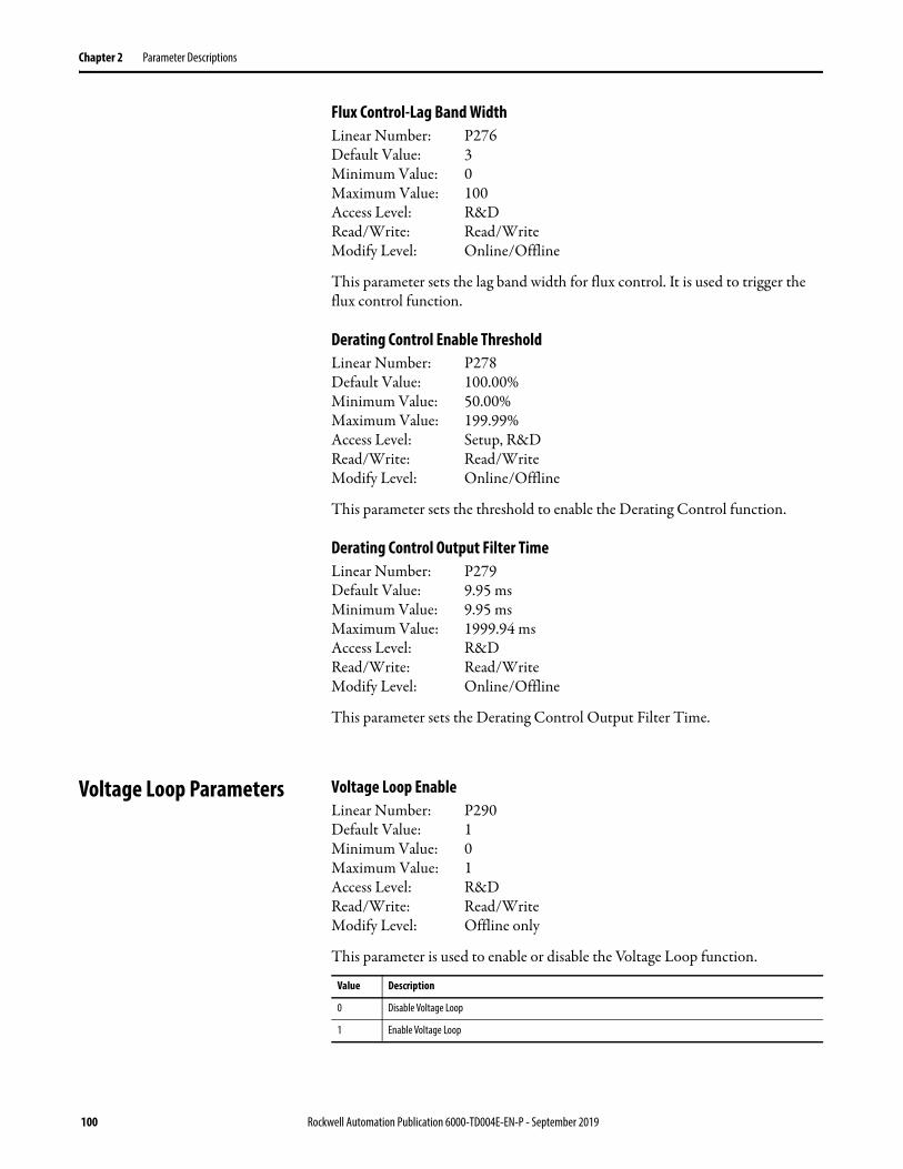
Chapter 2 Parameter Descriptions
Flux Control-Lag Band WidthLinear Number: P276Default Value: 3Minimum Value: 0Maximum Value: 100Access Level: R&DRead/Write: Read/WriteModify Level: Online/Offline
This parameter sets the lag band width for flux control. It is used to trigger the flux control function.
Derating Control Enable ThresholdLinear Number: P278Default Value: 100.00%Minimum Value: 50.00%Maximum Value: 199.99%Access Level: Setup, R&DRead/Write: Read/WriteModify Level: Online/Offline
This parameter sets the threshold to enable the Derating Control function.
Derating Control Output Filter TimeLinear Number: P279Default Value: 9.95 msMinimum Value: 9.95 msMaximum Value: 1999.94 msAccess Level: R&DRead/Write: Read/WriteModify Level: Online/Offline
This parameter sets the Derating Control Output Filter Time.
Voltage Loop Parameters Voltage Loop EnableLinear Number: P290Default Value: 1Minimum Value: 0Maximum Value: 1Access Level: R&DRead/Write: Read/WriteModify Level: Offline only
This parameter is used to enable or disable the Voltage Loop function.
Value Description
0 Disable Voltage Loop
1 Enable Voltage Loop
100 Rockwell Automation Publication 6000-TD004E-EN-P - September 2019
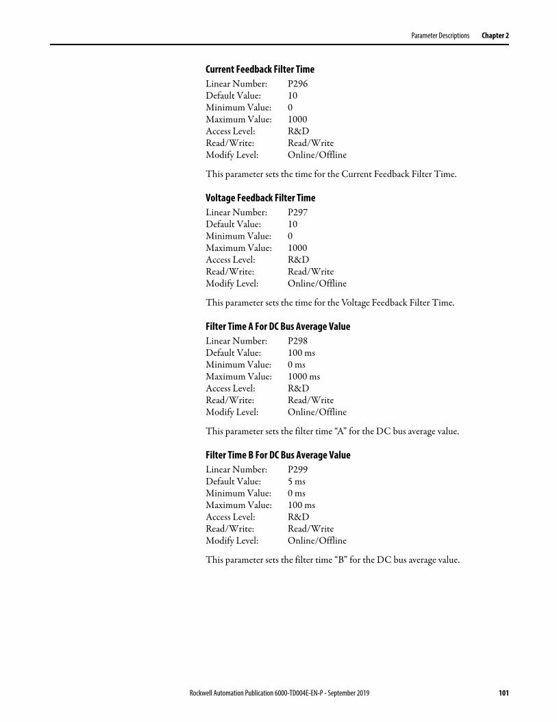
Parameter Descriptions Chapter 2
Current Feedback Filter TimeLinear Number: P296Default Value: 10Minimum Value: 0Maximum Value: 1000Access Level: R&DRead/Write: Read/WriteModify Level: Online/Offline
This parameter sets the time for the Current Feedback Filter Time.
Voltage Feedback Filter TimeLinear Number: P297Default Value: 10Minimum Value: 0Maximum Value: 1000Access Level: R&DRead/Write: Read/WriteModify Level: Online/Offline
This parameter sets the time for the Voltage Feedback Filter Time.
Filter Time A For DC Bus Average ValueLinear Number: P298Default Value: 100 msMinimum Value: 0 msMaximum Value: 1000 msAccess Level: R&DRead/Write: Read/WriteModify Level: Online/Offline
This parameter sets the filter time “A” for the DC bus average value.
Filter Time B For DC Bus Average ValueLinear Number: P299Default Value: 5 msMinimum Value: 0 msMaximum Value: 100 msAccess Level: R&DRead/Write: Read/WriteModify Level: Online/Offline
This parameter sets the filter time “B” for the DC bus average value.
Rockwell Automation Publication 6000-TD004E-EN-P - September 2019 101

Chapter 2 Parameter Descriptions
Low Voltage Ride Through Parameters
Low Voltage Ride Through Recovery Voltage Boost CoefficientLinear Number: P280Default Value: 0%Minimum Value: 0%Maximum Value: 100%Access Level: R&DRead/Write: Read/WriteModify Level: Online/Offline
This parameter sets the Low Voltage Ride Through Recovery Voltage Boost Coefficient.
Low Voltage Ride Through Min Time IntervalLinear Number: P281Default Value: 10 sMinimum Value: 0 sMaximum Value: 1000 sAccess Level: Setup, R&DRead/Write: Read/WriteModify Level: Online/Offline
This parameter sets the minimum time interval for Low Voltage Ride Through.
Low Voltage Ride Through Min Frequency LimitLinear Number: P282Default Value: 5%Minimum Value: 5%Maximum Value: 100%Access Level: Setup, R&DRead/Write: Read/WriteModify Level: Offline only
This parameter sets the minimum frequency limit for Low Voltage Ride Through.
Low Voltage Ride Through EnableLinear Number: P283Default Value: 1Minimum Value: 0Maximum Value: 1Access Level: Setup, R&DRead/Write: Read/WriteModify Level: Online/Offline
This parameter is used to enable or disable the Low Voltage Ride Through function.
Value Description
0 Disable Low Voltage Ride Through
1 Enable Low Voltage Ride Through
102 Rockwell Automation Publication 6000-TD004E-EN-P - September 2019
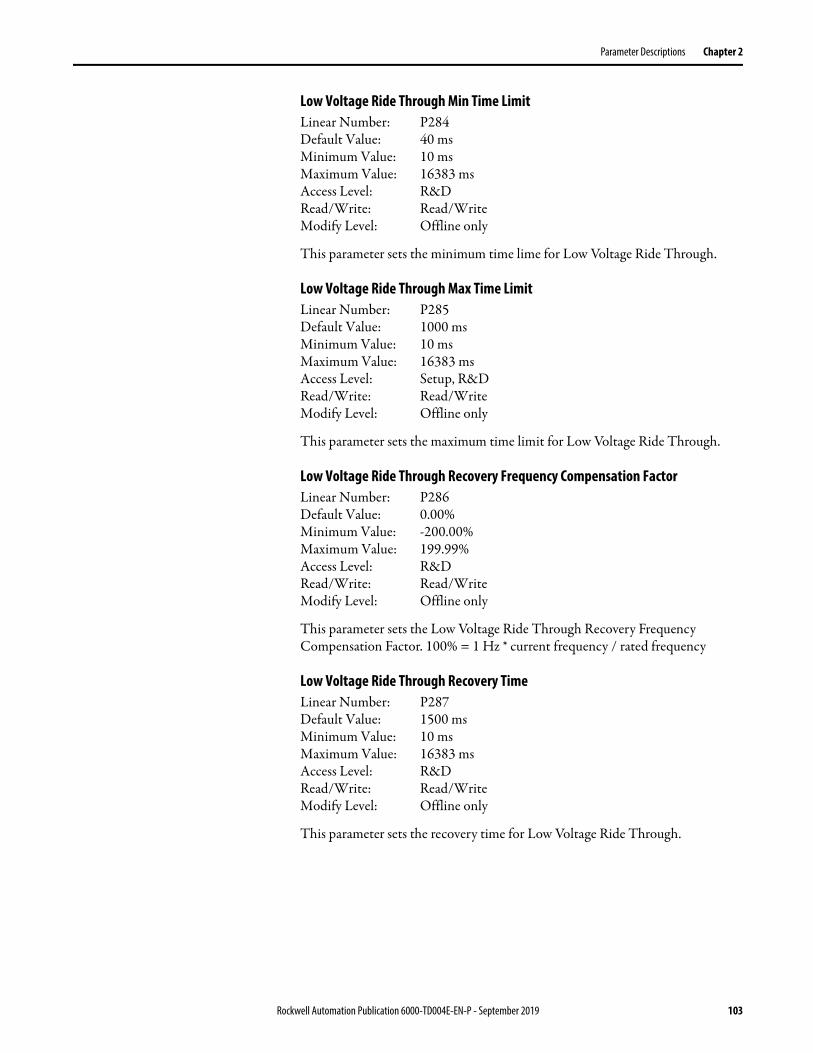
Parameter Descriptions Chapter 2
Low Voltage Ride Through Min Time LimitLinear Number: P284Default Value: 40 msMinimum Value: 10 msMaximum Value: 16383 msAccess Level: R&DRead/Write: Read/WriteModify Level: Offline only
This parameter sets the minimum time lime for Low Voltage Ride Through.
Low Voltage Ride Through Max Time LimitLinear Number: P285Default Value: 1000 msMinimum Value: 10 msMaximum Value: 16383 msAccess Level: Setup, R&DRead/Write: Read/WriteModify Level: Offline only
This parameter sets the maximum time limit for Low Voltage Ride Through.
Low Voltage Ride Through Recovery Frequency Compensation FactorLinear Number: P286Default Value: 0.00%Minimum Value: -200.00%Maximum Value: 199.99%Access Level: R&DRead/Write: Read/WriteModify Level: Offline only
This parameter sets the Low Voltage Ride Through Recovery Frequency Compensation Factor. 100% = 1 Hz * current frequency / rated frequency
Low Voltage Ride Through Recovery TimeLinear Number: P287Default Value: 1500 msMinimum Value: 10 msMaximum Value: 16383 msAccess Level: R&DRead/Write: Read/WriteModify Level: Offline only
This parameter sets the recovery time for Low Voltage Ride Through.
Rockwell Automation Publication 6000-TD004E-EN-P - September 2019 103
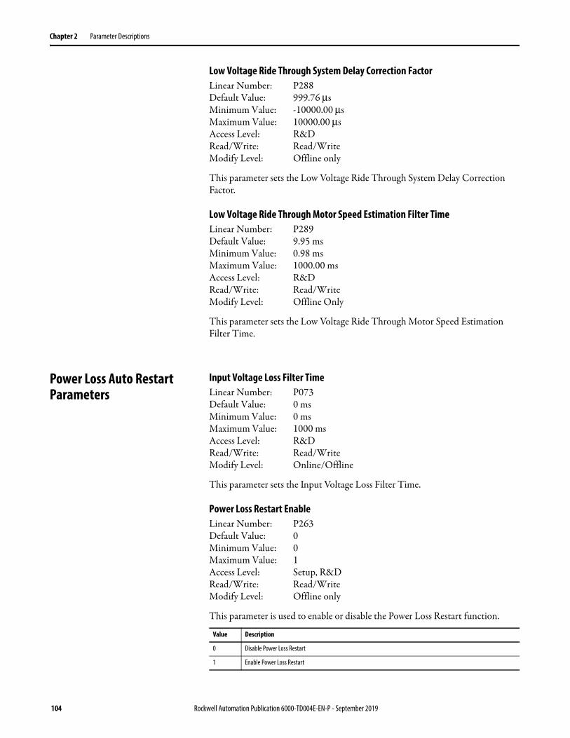
Chapter 2 Parameter Descriptions
Low Voltage Ride Through System Delay Correction FactorLinear Number: P288Default Value: 999.76 µsMinimum Value: -10000.00 µsMaximum Value: 10000.00 µsAccess Level: R&DRead/Write: Read/WriteModify Level: Offline only
This parameter sets the Low Voltage Ride Through System Delay Correction Factor.
Low Voltage Ride Through Motor Speed Estimation Filter TimeLinear Number: P289Default Value: 9.95 msMinimum Value: 0.98 msMaximum Value: 1000.00 msAccess Level: R&DRead/Write: Read/WriteModify Level: Offline Only
This parameter sets the Low Voltage Ride Through Motor Speed Estimation Filter Time.
Power Loss Auto Restart Parameters
Input Voltage Loss Filter TimeLinear Number: P073Default Value: 0 msMinimum Value: 0 msMaximum Value: 1000 msAccess Level: R&DRead/Write: Read/WriteModify Level: Online/Offline
This parameter sets the Input Voltage Loss Filter Time.
Power Loss Restart EnableLinear Number: P263Default Value: 0Minimum Value: 0Maximum Value: 1Access Level: Setup, R&DRead/Write: Read/WriteModify Level: Offline only
This parameter is used to enable or disable the Power Loss Restart function.
Value Description
0 Disable Power Loss Restart
1 Enable Power Loss Restart
104 Rockwell Automation Publication 6000-TD004E-EN-P - September 2019
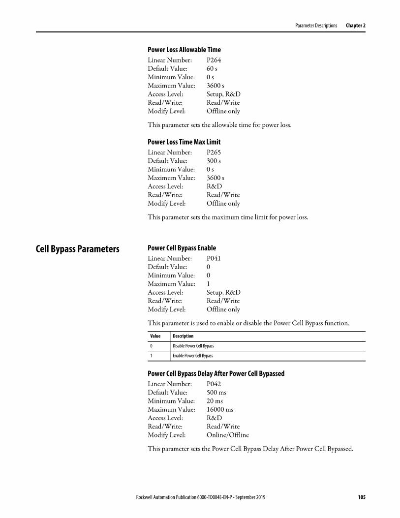
Parameter Descriptions Chapter 2
Power Loss Allowable TimeLinear Number: P264Default Value: 60 sMinimum Value: 0 sMaximum Value: 3600 sAccess Level: Setup, R&DRead/Write: Read/WriteModify Level: Offline only
This parameter sets the allowable time for power loss.
Power Loss Time Max LimitLinear Number: P265Default Value: 300 sMinimum Value: 0 sMaximum Value: 3600 sAccess Level: R&DRead/Write: Read/WriteModify Level: Offline only
This parameter sets the maximum time limit for power loss.
Cell Bypass Parameters Power Cell Bypass EnableLinear Number: P041Default Value: 0Minimum Value: 0Maximum Value: 1Access Level: Setup, R&DRead/Write: Read/WriteModify Level: Offline only
This parameter is used to enable or disable the Power Cell Bypass function.
Power Cell Bypass Delay After Power Cell BypassedLinear Number: P042Default Value: 500 msMinimum Value: 20 msMaximum Value: 16000 msAccess Level: R&DRead/Write: Read/WriteModify Level: Online/Offline
This parameter sets the Power Cell Bypass Delay After Power Cell Bypassed.
Value Description
0 Disable Power Cell Bypass
1 Enable Power Cell Bypass
Rockwell Automation Publication 6000-TD004E-EN-P - September 2019 105

Chapter 2 Parameter Descriptions
Power Cell Bypass Upper Limit For Bypassed Feedback TimeLinear Number: P043Default Value: 100 msMinimum Value: 30 msMaximum Value: 500 msAccess Level: R&DRead/Write: Read/WriteModify Level: Online/Offline
This parameter sets the Power Cell Bypass Upper Limit For Bypassed Feedback Time.
Power Cell Bypass Fault Simulation Power Cell CountLinear Number: P044Default Value: 0Minimum Value: 0Maximum Value: 3Access Level: Setup, R&DRead/Write: Read/WriteModify Level: Online/Offline
This parameter sets the power cell count for power cell bypass fault simulation.
Power Cell Bypass Upper Limit Time For Over TemperatureLinear Number: P057Default Value: 10 sMinimum Value: 0 sMaximum Value: 32767 sAccess Level: R&DRead/Write: Read/WriteModify Level: Online/Offline
This parameter sets the Power Cell Bypass Upper Limit Time For Over Temperature.
Power Cell Bypass Phase A Cell Number For SimulationLinear Number: P058Default Value: 0Minimum Value: 0Maximum Value: 9Access Level: Setup, R&DRead/Write: Read/WriteModify Level: Online/Offline
This parameter sets the Power Cell Bypass Phase A Cell Number For Simulation. Set this parameter greater than zero when simulating a cell fault.
106 Rockwell Automation Publication 6000-TD004E-EN-P - September 2019

Parameter Descriptions Chapter 2
Power Cell Bypass Phase B Cell Number For SimulationLinear Number: P059Default Value: 0Minimum Value: 0Maximum Value: 18Access Level: Setup, R&DRead/Write: Read/WriteModify Level: Online/Offline
This parameter sets the Power Cell Bypass Phase B Cell Number For Simulation. Set this parameter greater than zero when simulating a cell fault.
Power Cell Bypass Phase C Cell Number For SimulationLinear Number: P060Default Value: 0Minimum Value: 0Maximum Value: 27Access Level: Setup, R&DRead/Write: Read/WriteModify Level: Online/Offline
This parameter sets the Power Cell Bypass Phase C Cell Number For Simulation. Set this parameter greater than zero when simulating a cell fault.
Power Cell Bypass Fault SimulationLinear Number: P061Default Value: 0Minimum Value: -32768Maximum Value: 32767Access Level: Setup, R&DRead/Write: Read/WriteModify Level: Online/Offline
This parameter sets the Power Cell Bypass Fault Simulation.
Power Cell Bypass Enable Frequency Range Lower LimitLinear Number: P065Default Value: 0.00%Minimum Value: 0.00%Maximum Value: 19.99%Access Level: Setup, R&DRead/Write: Read/WriteModify Level: Online/Offline
This parameter sets the lower limit for Power Cell Bypass Enable Frequency Range.
Rockwell Automation Publication 6000-TD004E-EN-P - September 2019 107

Chapter 2 Parameter Descriptions
Power Cell Bypass Restart Enable After Power Cell BypassedLinear Number: P066Default Value: 1Minimum Value: 0Maximum Value: 1Access Level: R&DRead/Write: Read/WriteModify Level: Offline only
This parameter is used to enable or disable the Power Cell Bypass Restart function.
One Phase Lost Filter TimeLinear Number: P068Default Value: 30 msMinimum Value: 5 msMaximum Value: 1000 msAccess Level: Setup, R&DRead/Write: Read/WriteModify Level: Online/Offline
This parameter sets the One Phase Lost Filter Time.
Power Cell Reactivation Time Upper Limit Linear Number: P078Default Value: 100 msMinimum Value: 0 msMaximum Value: 200 msAccess Level: R&DRead/Write: Read/WriteModify Level: Online/Offline
This parameter sets the upper limit for power cell reactivation time.
Value Description
0 Disable Power Cell Bypass Restart
1 Enable Power Cell Bypass Restart
108 Rockwell Automation Publication 6000-TD004E-EN-P - September 2019
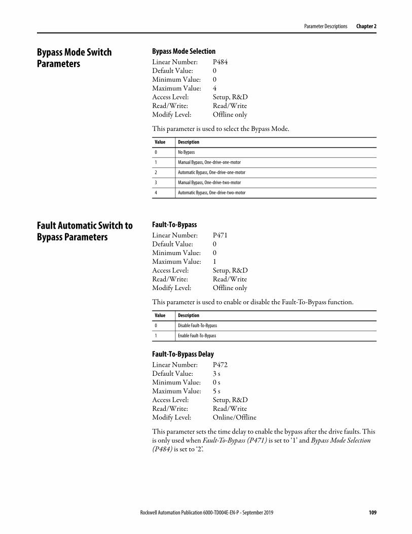
Parameter Descriptions Chapter 2
Bypass Mode Switch Parameters
Bypass Mode SelectionLinear Number: P484Default Value: 0Minimum Value: 0Maximum Value: 4Access Level: Setup, R&DRead/Write: Read/WriteModify Level: Offline only
This parameter is used to select the Bypass Mode.
Fault Automatic Switch to Bypass Parameters
Fault-To-BypassLinear Number: P471Default Value: 0Minimum Value: 0Maximum Value: 1Access Level: Setup, R&DRead/Write: Read/WriteModify Level: Offline only
This parameter is used to enable or disable the Fault-To-Bypass function.
Fault-To-Bypass DelayLinear Number: P472Default Value: 3 sMinimum Value: 0 sMaximum Value: 5 sAccess Level: Setup, R&DRead/Write: Read/WriteModify Level: Online/Offline
This parameter sets the time delay to enable the bypass after the drive faults. This is only used when Fault-To-Bypass (P471) is set to ‘1’ and Bypass Mode Selection (P484) is set to ‘2’.
Value Description
0 No Bypass
1 Manual Bypass, One-drive-one-motor
2 Automatic Bypass, One-drive-one-motor
3 Manual Bypass, One-drive-two-motor
4 Automatic Bypass, One-drive-two-motor
Value Description
0 Disable Fault-To-Bypass
1 Enable Fault-To-Bypass
Rockwell Automation Publication 6000-TD004E-EN-P - September 2019 109
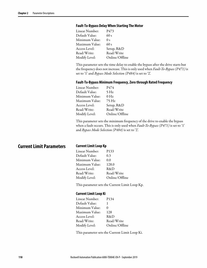
Chapter 2 Parameter Descriptions
Fault-To-Bypass Delay When Starting The MotorLinear Number: P473Default Value: 60 sMinimum Value: 0 sMaximum Value: 60 sAccess Level: Setup, R&DRead/Write: Read/WriteModify Level: Online/Offline
This parameter sets the time delay to enable the bypass after the drive starts but the frequency does not increase. This is only used when Fault-To-Bypass (P471) is set to ‘1’ and Bypass Mode Selection (P484) is set to ‘2’.
Fault-To-Bypass Minimum Frequency, Zero through Rated FrequencyLinear Number: P474Default Value: 5 HzMinimum Value: 0 HzMaximum Value: 75 HzAccess Level: Setup, R&DRead/Write: Read/WriteModify Level: Online/Offline
This parameter sets the minimum frequency of the drive to enable the bypass when a fault occurs. This is only used when Fault-To-Bypass (P471) is set to ‘1’ and Bypass Mode Selection (P484) is set to ‘2’.
Current Limit Parameters Current Limit Loop KpLinear Number: P133Default Value: 0.3Minimum Value: 0.0Maximum Value: 128.0Access Level: R&DRead/Write: Read/WriteModify Level: Online/Offline
This parameter sets the Current Limit Loop Kp.
Current Limit Loop KiLinear Number: P134Default Value: 1Minimum Value: 0Maximum Value: 128Access Level: R&DRead/Write: Read/WriteModify Level: Online/Offline
This parameter sets the Current Limit Loop Ki.
110 Rockwell Automation Publication 6000-TD004E-EN-P - September 2019

Parameter Descriptions Chapter 2
Current Limit Loop KdLinear Number: P135Default Value: 0Minimum Value: 0Maximum Value: 12800Access Level: R&DRead/Write: Read/WriteModify Level: Online/Offline
This parameter sets the Current Limit Loop Kd (*0.001).
Current Limitation EnableLinear Number: P436Default Value: 1Minimum Value: 0Maximum Value: 1Access Level: Setup, R&DRead/Write: Read/WriteModify Level: Online/Offline
This parameter is used to enable or disable the Current Limitation function.
Current Limitation Enable Frequency Range Lower LimitLinear Number: P438Default Value: 0%Minimum Value: 0%Maximum Value: 100%Access Level: Setup, R&DRead/Write: Read/WriteModify Level: Online/Offline
This parameter sets the lower limit for Current Limitation Enable Frequency Range.
Current Limitation ThresholdLinear Number: P441Default Value: 100.00%Minimum Value: 0.00%Maximum Value: 399.99%Access Level: Setup, R&DRead/Write: Read/WriteModify Level: Online/Offline
This parameter sets the Current Limitation Threshold.
Value Description
0 Disable Current Limitations
1 Enable Current Limitation
Rockwell Automation Publication 6000-TD004E-EN-P - September 2019 111
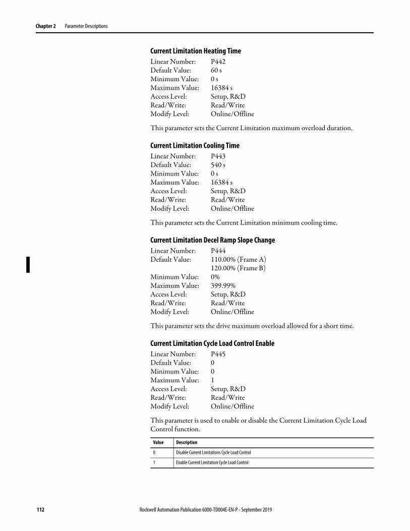
Chapter 2 Parameter Descriptions
Current Limitation Heating TimeLinear Number: P442Default Value: 60 sMinimum Value: 0 sMaximum Value: 16384 sAccess Level: Setup, R&DRead/Write: Read/WriteModify Level: Online/Offline
This parameter sets the Current Limitation maximum overload duration.
Current Limitation Cooling TimeLinear Number: P443Default Value: 540 sMinimum Value: 0 sMaximum Value: 16384 sAccess Level: Setup, R&DRead/Write: Read/WriteModify Level: Online/Offline
This parameter sets the Current Limitation minimum cooling time.
Current Limitation Decel Ramp Slope ChangeLinear Number: P444Default Value: 110.00% (Frame A)
120.00% (Frame B)Minimum Value: 0%Maximum Value: 399.99%Access Level: Setup, R&DRead/Write: Read/WriteModify Level: Online/Offline
This parameter sets the drive maximum overload allowed for a short time.
Current Limitation Cycle Load Control EnableLinear Number: P445Default Value: 0Minimum Value: 0Maximum Value: 1Access Level: Setup, R&DRead/Write: Read/WriteModify Level: Online/Offline
This parameter is used to enable or disable the Current Limitation Cycle Load Control function.
Value Description
0 Disable Current Limitations Cycle Load Control
1 Enable Current Limitation Cycle Load Control
112 Rockwell Automation Publication 6000-TD004E-EN-P - September 2019
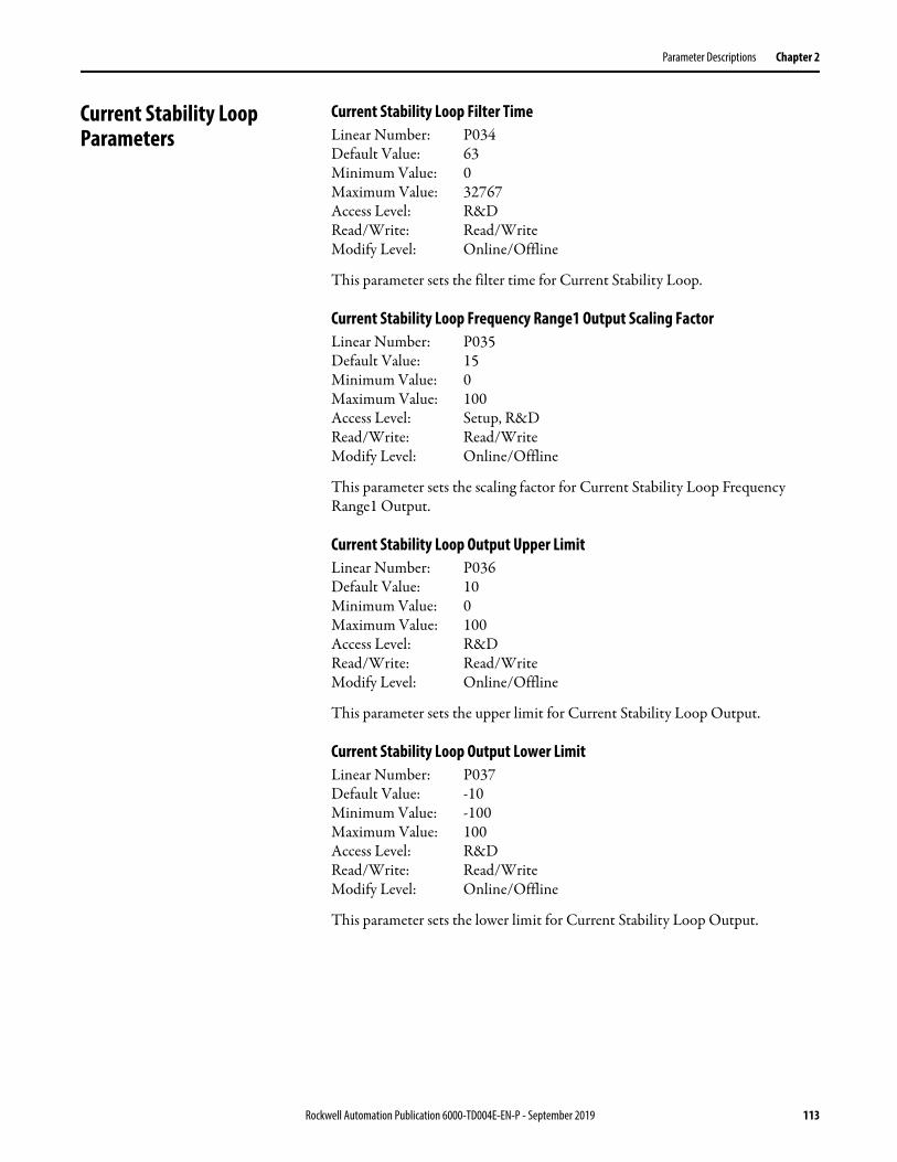
Parameter Descriptions Chapter 2
Current Stability Loop Parameters
Current Stability Loop Filter TimeLinear Number: P034Default Value: 63Minimum Value: 0Maximum Value: 32767Access Level: R&DRead/Write: Read/WriteModify Level: Online/Offline
This parameter sets the filter time for Current Stability Loop.
Current Stability Loop Frequency Range1 Output Scaling FactorLinear Number: P035Default Value: 15Minimum Value: 0Maximum Value: 100Access Level: Setup, R&DRead/Write: Read/WriteModify Level: Online/Offline
This parameter sets the scaling factor for Current Stability Loop Frequency Range1 Output.
Current Stability Loop Output Upper LimitLinear Number: P036Default Value: 10Minimum Value: 0Maximum Value: 100Access Level: R&DRead/Write: Read/WriteModify Level: Online/Offline
This parameter sets the upper limit for Current Stability Loop Output.
Current Stability Loop Output Lower LimitLinear Number: P037Default Value: -10Minimum Value: -100Maximum Value: 100Access Level: R&DRead/Write: Read/WriteModify Level: Online/Offline
This parameter sets the lower limit for Current Stability Loop Output.
Rockwell Automation Publication 6000-TD004E-EN-P - September 2019 113
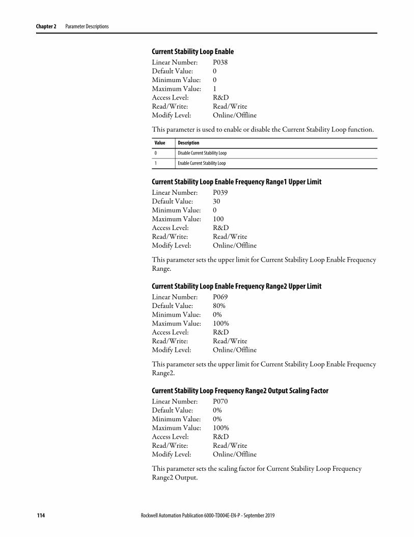
Chapter 2 Parameter Descriptions
Current Stability Loop EnableLinear Number: P038Default Value: 0Minimum Value: 0Maximum Value: 1Access Level: R&DRead/Write: Read/WriteModify Level: Online/Offline
This parameter is used to enable or disable the Current Stability Loop function.
Current Stability Loop Enable Frequency Range1 Upper LimitLinear Number: P039Default Value: 30Minimum Value: 0Maximum Value: 100Access Level: R&DRead/Write: Read/WriteModify Level: Online/Offline
This parameter sets the upper limit for Current Stability Loop Enable Frequency Range.
Current Stability Loop Enable Frequency Range2 Upper LimitLinear Number: P069Default Value: 80%Minimum Value: 0%Maximum Value: 100%Access Level: R&DRead/Write: Read/WriteModify Level: Online/Offline
This parameter sets the upper limit for Current Stability Loop Enable Frequency Range2.
Current Stability Loop Frequency Range2 Output Scaling FactorLinear Number: P070Default Value: 0%Minimum Value: 0%Maximum Value: 100%Access Level: R&DRead/Write: Read/WriteModify Level: Online/Offline
This parameter sets the scaling factor for Current Stability Loop Frequency Range2 Output.
Value Description
0 Disable Current Stability Loop
1 Enable Current Stability Loop
114 Rockwell Automation Publication 6000-TD004E-EN-P - September 2019
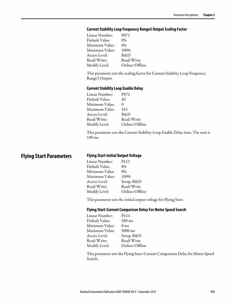
Parameter Descriptions Chapter 2
Current Stability Loop Frequency Range3 Output Scaling FactorLinear Number: P071Default Value: 0%Minimum Value: 0%Maximum Value: 100%Access Level: R&DRead/Write: Read/WriteModify Level: Online/Offline
This parameter sets the scaling factor for Current Stability Loop Frequency Range3 Output.
Current Stability Loop Enable DelayLinear Number: P072Default Value: 10Minimum Value: 0Maximum Value: 163Access Level: R&DRead/Write: Read/WriteModify Level: Online/Offline
This parameter sets the Current Stability Loop Enable Delay time. The unit is 100 ms.
Flying Start Parameters Flying Start-Initial Output VoltageLinear Number: P113Default Value: 8%Minimum Value: 0%Maximum Value: 100%Access Level: Setup, R&DRead/Write: Read/WriteModify Level: Online/Offline
This parameter sets the initial output voltage for Flying Start.
Flying Start-Current Comparison Delay For Motor Speed SearchLinear Number: P114Default Value: 500 msMinimum Value: 0 msMaximum Value: 5000 msAccess Level: Setup, R&DRead/Write: Read/WriteModify Level: Online/Offline
This parameter sets the Flying Start-Current Comparison Delay for Motor Speed Search.
Rockwell Automation Publication 6000-TD004E-EN-P - September 2019 115

Chapter 2 Parameter Descriptions
Flying Start-Current Threshold For Successful Motor Speed SearchLinear Number: P115Default Value: 4.99 puMinimum Value: 0.00 puMaximum Value: 100.00 puAccess Level: Setup, R&DRead/Write: Read/WriteModify Level: Online/Offline
This parameter sets the Flying Start-Current Threshold for successful Motor Speed Search.
Flying Start Voltage ThresholdLinear Number: P187Default Value: 3%Minimum Value: 0%Maximum Value: 100%Access Level: Setup, R&DRead/Write: Read/WriteModify Level: Online/Offline
This parameter sets the Flying Start Voltage Threshold.
Flying Start Compensation EnableLinear Number: P393Default Value: 1Minimum Value: 0Maximum Value: 1Access Level: Setup, R&DRead/Write: Read/WriteModify Level: Online/Offline
This parameter is used to enable or disable Flying Start Compensation.
Flying Start Compensation Current ThresholdLinear Number: P394Default Value: 50.00Minimum Value: 0.00Maximum Value: 399.99Access Level: Setup, R&DRead/Write: Read/WriteModify Level: Online/Offline
This parameter sets the threshold for the Flying Start Compensation Current.
Value Description
0 Disable Flying Start Compensation
1 Enable Flying Start Compensation
116 Rockwell Automation Publication 6000-TD004E-EN-P - September 2019

Parameter Descriptions Chapter 2
Flying Start Compensation Frequency Reduce SpeedLinear Number: P395Default Value: 50Minimum Value: 10Maximum Value: 16384Access Level: Setup, R&DRead/Write: Read/WriteModify Level: Online/Offline
This parameter sets the Flying Start Compensation Frequency Reduce Speed.
Flying Start Compensation Defer Restore Voltage Speed Current ThresholdLinear Number: P408Default Value: 25.00Minimum Value: 20.00Maximum Value: 399.99Access Level: R&DRead/Write: Read/WriteModify Level: Online/Offline
This parameter sets the Defer Restore Voltage Speed Current Threshold for Flying Start Compensation.
Flying Start Compensation Current Threshold for Fast CompensationLinear Number: P410Default Value: 60.00Minimum Value: 0.00Maximum Value: 399.99Access Level: R&DRead/Write: Read/WriteModify Level: Online/Offline
This parameter sets the Current Threshold for Fast Compensation for Flying Start Compensation.
Flying Start ModeLinear Number: P416Default Value: 0Minimum Value: 0Maximum Value: 3Access Level: Setup, R&DRead/Write: Read/WriteModify Level: Online/Offline
This parameter sets the mode for Flying Start.
Value Description
0 Disable
1 Set Frequency
2 Stop Frequency plus 5 Hz
3 Rated Frequency
Rockwell Automation Publication 6000-TD004E-EN-P - September 2019 117

Chapter 2 Parameter Descriptions
Flying Start Motor Speed Search TimeoutLinear Number: P417Default Value: 50 sMinimum Value: 0 sMaximum Value: 1000 sAccess Level: Setup, R&DRead/Write: Read/WriteModify Level: Online/Offline
This parameter sets the Flying Start Motor Speed Search Timeout.
Flying Start Voltage Recovery Time (Low Speed Region)Linear Number: P457Default Value: 10.00 sMinimum Value: 0.00 sMaximum Value: 163.84 sAccess Level: Setup, R&DRead/Write: Read/WriteModify Level: Online/Offline
This parameter sets the low speed region for Flying Start Voltage Recovery Time.
Flying Start Voltage Recovery Time (High Speed Region)Linear Number: P459Default Value: 10.00 sMinimum Value: 0.00 sMaximum Value: 163.84 sAccess Level: Setup, R&DRead/Write: Read/WriteModify Level: Online/Offline
This parameter sets the high speed region for Flying Start Voltage Recovery Time.
Flying Start Low/High Speed Regions BoundaryLinear Number: P463Default Value: 16%Minimum Value: 0%Maximum Value: 100%Access Level: Setup, R&DRead/Write: Read/WriteModify Level: Online/Offline
This parameter sets the boundary for Flying Start-Low/High Speed Regions.
118 Rockwell Automation Publication 6000-TD004E-EN-P - September 2019
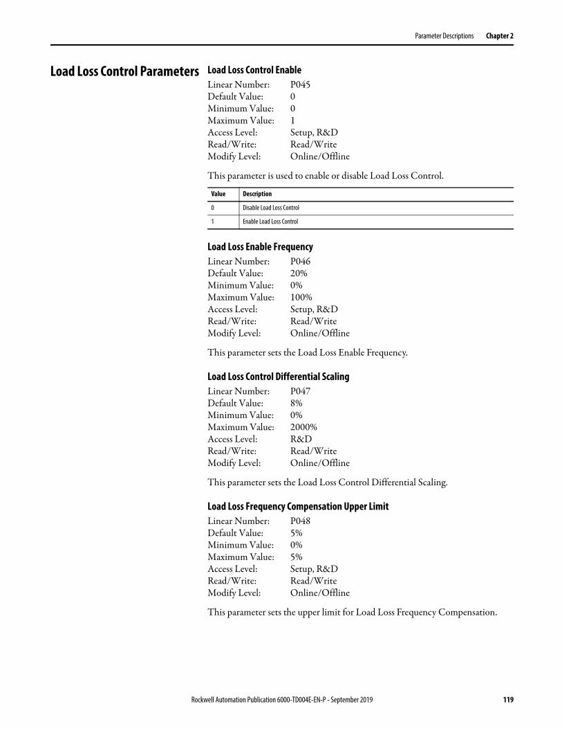
Parameter Descriptions Chapter 2
Load Loss Control Parameters Load Loss Control EnableLinear Number: P045Default Value: 0Minimum Value: 0Maximum Value: 1Access Level: Setup, R&DRead/Write: Read/WriteModify Level: Online/Offline
This parameter is used to enable or disable Load Loss Control.
Load Loss Enable FrequencyLinear Number: P046Default Value: 20%Minimum Value: 0%Maximum Value: 100%Access Level: Setup, R&DRead/Write: Read/WriteModify Level: Online/Offline
This parameter sets the Load Loss Enable Frequency.
Load Loss Control Differential ScalingLinear Number: P047Default Value: 8%Minimum Value: 0%Maximum Value: 2000%Access Level: R&DRead/Write: Read/WriteModify Level: Online/Offline
This parameter sets the Load Loss Control Differential Scaling.
Load Loss Frequency Compensation Upper LimitLinear Number: P048Default Value: 5%Minimum Value: 0%Maximum Value: 5%Access Level: Setup, R&DRead/Write: Read/WriteModify Level: Online/Offline
This parameter sets the upper limit for Load Loss Frequency Compensation.
Value Description
0 Disable Load Loss Control
1 Enable Load Loss Control
Rockwell Automation Publication 6000-TD004E-EN-P - September 2019 119

Chapter 2 Parameter Descriptions
Load Loss Control Scaling FactorLinear Number: P049Default Value: 0%Minimum Value: 0%Maximum Value: 2000%Access Level: R&DRead/Write: Read/WriteModify Level: Online/Offline
This parameter sets the scaling factor for Load Loss Control.
Load Loss Control Integral TimeLinear Number: P050Default Value: 0 msMinimum Value: 0 msMaximum Value: 100 msAccess Level: R&DRead/Write: Read/WriteModify Level: Online/Offline
This parameter sets the Load Loss Control Integral Time.
Load Loss Control Filter TimeLinear Number: P051Default Value: 100 msMinimum Value: 0 msMaximum Value: 200 msAccess Level: R&DRead/Write: Read/WriteModify Level: Online/Offline
This parameter sets the Load Loss Control Filter Time.
Load Loss Enable Current ThresholdLinear Number: P052Default Value: 10%Minimum Value: 0%Maximum Value: 100%Access Level: R&DRead/Write: Read/WriteModify Level: Online/Offline
This parameter sets the Load Loss Enable Current Threshold.
120 Rockwell Automation Publication 6000-TD004E-EN-P - September 2019

Parameter Descriptions Chapter 2
Load Loss Control Exit DelayLinear Number: P053Default Value: 5000 msMinimum Value: 0 msMaximum Value: 16000 msAccess Level: R&DRead/Write: Read/WriteModify Level: Online/Offline
This parameter sets the Load Loss Control Exit Delay.
Motor Auto-tune Parameters Motor Autotune SelectionLinear Number: P121Default Value: 0Minimum Value: 0Maximum Value: 3Access Level: Setup, R&DRead/Write: Read/WriteModify Level: Offline only
This parameter is used to select the method of Motor Autotune. When Motor Autotune Selection (P121) is set to “1”, the motor parameters tuning starts, and the parameter is automatically set to “0” when the autotune is completed.
When Motor Autotune Selection (P121) is set to “2” or “3”, press the start button on the drive to initiate the autotune. After the autotune is complete the parameter is automatically set to “0” and the drive is stopped.
Motor Autotune DelayLinear Number: P122Default Value: 2000 msMinimum Value: 0 msMaximum Value: 32767 msAccess Level: Setup, R&DRead/Write: Read/WriteModify Level: Online/Offline
This parameter sets the Motor Autotune Delay.
Value Description
0 Manual Configuration
1 Nameplate Calculation
2 Static Autotune
3 Rotating Autotune
Rockwell Automation Publication 6000-TD004E-EN-P - September 2019 121

Chapter 2 Parameter Descriptions
Motor Autotune Filter TimeLinear Number: P123Default Value: 10 msMinimum Value: 0 msMaximum Value: 32767 msAccess Level: Setup, R&DRead/Write: Read/WriteModify Level: Online/Offline
This parameter sets the Motor Autotune Filter Time.
Motor Autotune Current Id KpLinear Number: P124Default Value: 0.01Minimum Value: 0.00Maximum Value: 128.00Access Level: Setup, R&DRead/Write: Read/WriteModify Level: Online/Offline
This parameter sets the Motor Autotune Current Id Kp.
Motor Autotune Current Id KiLinear Number: P125Default Value: 0.1Minimum Value: 0.0Maximum Value: 128.0Access Level: Setup, R&DRead/Write: Read/WriteModify Level: Online/Offline
This parameter sets the Motor Autotune Current Id Ki.
Motor Autotune Current Iq KpLinear Number: P124Default Value: 0.01Minimum Value: 0.00Maximum Value: 128.00Access Level: Setup, R&DRead/Write: Read/WriteModify Level: Online/Offline
This parameter sets the Motor Autotune Current Iq Kp.
122 Rockwell Automation Publication 6000-TD004E-EN-P - September 2019
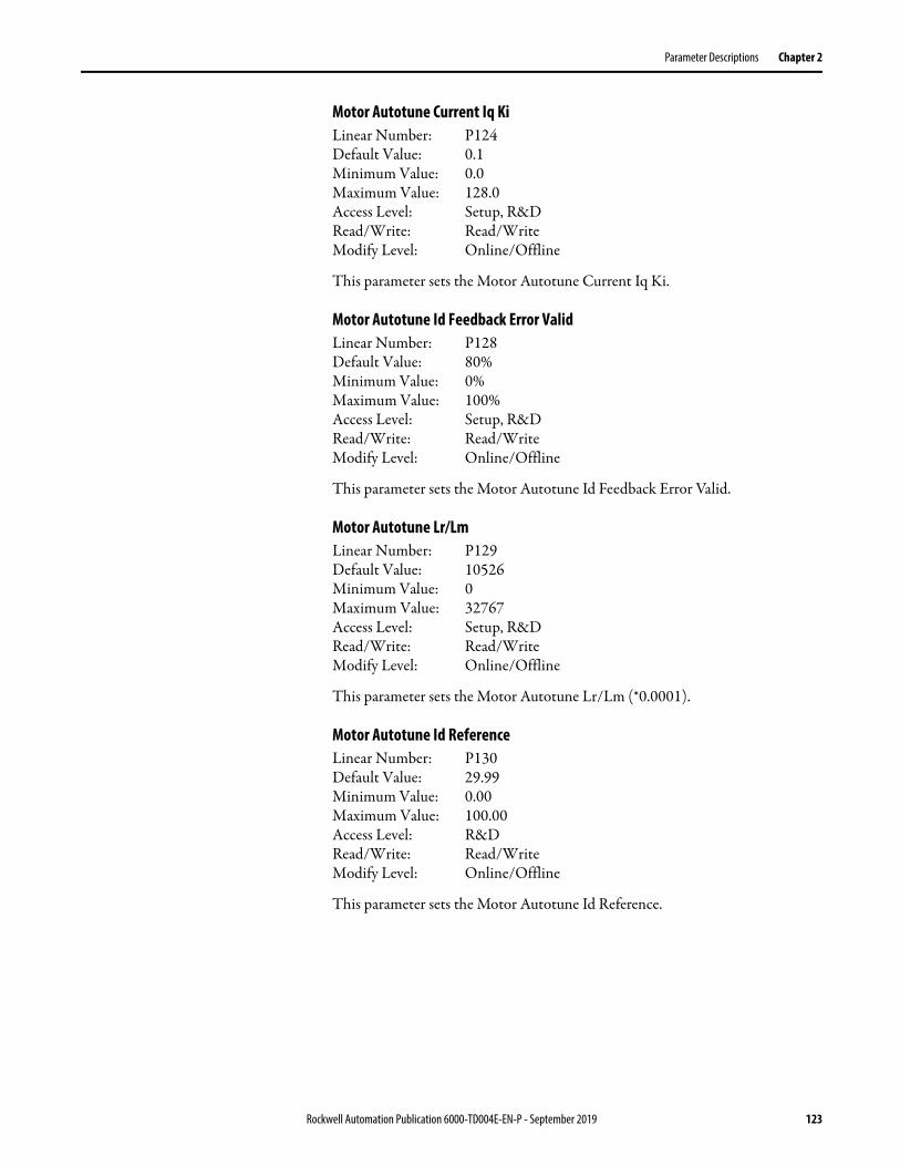
Parameter Descriptions Chapter 2
Motor Autotune Current Iq KiLinear Number: P124Default Value: 0.1Minimum Value: 0.0Maximum Value: 128.0Access Level: Setup, R&DRead/Write: Read/WriteModify Level: Online/Offline
This parameter sets the Motor Autotune Current Iq Ki.
Motor Autotune Id Feedback Error ValidLinear Number: P128Default Value: 80%Minimum Value: 0%Maximum Value: 100%Access Level: Setup, R&DRead/Write: Read/WriteModify Level: Online/Offline
This parameter sets the Motor Autotune Id Feedback Error Valid.
Motor Autotune Lr/LmLinear Number: P129Default Value: 10526Minimum Value: 0Maximum Value: 32767Access Level: Setup, R&DRead/Write: Read/WriteModify Level: Online/Offline
This parameter sets the Motor Autotune Lr/Lm (*0.0001).
Motor Autotune Id ReferenceLinear Number: P130Default Value: 29.99Minimum Value: 0.00Maximum Value: 100.00Access Level: R&DRead/Write: Read/WriteModify Level: Online/Offline
This parameter sets the Motor Autotune Id Reference.
Rockwell Automation Publication 6000-TD004E-EN-P - September 2019 123

Chapter 2 Parameter Descriptions
Motor Autotune Iq ReferenceLinear Number: P131Default Value: 0Minimum Value: 0Maximum Value: 100Access Level: R&DRead/Write: Read/WriteModify Level: Online/Offline
This parameter sets the Motor Autotune Iq Reference.
Motor Autotune Time LimitLinear Number: P132Default Value: 5000 minMinimum Value: 0 minMaximum Value: 32767 minAccess Level: R&DRead/Write: Read/WriteModify Level: Online/Offline
This parameter sets the Motor Autotune Time Limit.
Motor Autotune Rs/RrLinear Number: P136Default Value: 1.30Minimum Value: 0.00Maximum Value: 327.67Access Level: Setup, R&DRead/Write: Read/WriteModify Level: Online/Offline
This parameter sets the Motor Autotune Rs/Rr.
Motor Rated CurrentLinear Number: P137Default Value: 0 AMinimum Value: 0 AMaximum Value: 32767 AAccess Level: Setup, R&DRead/Write: Read/WriteModify Level: Online/Offline
This parameter sets the motor rated current.
124 Rockwell Automation Publication 6000-TD004E-EN-P - September 2019

Parameter Descriptions Chapter 2
Motor Stator Resistance RsLinear Number: P138Default Value: 0 ΩMinimum Value: 0 ΩMaximum Value: 10 ΩAccess Level: Setup, R&DRead/Write: Read/WriteModify Level: Online/Offline
This parameter sets the Motor Stator Resistance Rs.
Motor Magnetizing Current IdLinear Number: P139Default Value: 30%Minimum Value: 0%Maximum Value: 100%Access Level: Setup, R&DRead/Write: Read/WriteModify Level: Online/Offline
This parameter sets the Motor Magnetizing Current Id.
Motor Rotor Resistance RrLinear Number: P140Default Value: 0 ΩMinimum Value: 0 ΩMaximum Value: 10 ΩAccess Level: Setup, R&DRead/Write: Read/WriteModify Level: Online/Offline
This parameter sets the Motor Rotor Resistance Rr.
Motor Magnetizing Inductance LmLinear Number: P141Default Value: 0.0 mHMinimum Value: 0.0 mHMaximum Value: 3276.7 mHAccess Level: Setup, R&DRead/Write: Read/WriteModify Level: Online/Offline
This parameter sets the Motor Magnetizing Inductance Lm.
Rockwell Automation Publication 6000-TD004E-EN-P - September 2019 125

Chapter 2 Parameter Descriptions
Motor Stator Leakage Inductance LIsLinear Number: P142Default Value: 0.0 mHMinimum Value: 0.0 mHMaximum Value: 3276.7 mHAccess Level: Setup, R&DRead/Write: Read/WriteModify Level: Online/Offline
This parameter sets the Motor Stator Leakage Inductance LIs.
Motor Rotor Leakage Inductance LIrLinear Number: P143Default Value: 0.0 mHMinimum Value: 0.0 mHMaximum Value: 3276.7 mHAccess Level: Setup, R&DRead/Write: Read/WriteModify Level: Online/Offline
This parameter sets the Motor Rotor Leakage Inductance LIr.
Motor Autotune Rs Upper LimitLinear Number: P178Default Value: 50%Minimum Value: 0%Maximum Value: 100%Access Level: R&DRead/Write: Read/WriteModify Level: Online/Offline
This parameter sets the Motor Autotune Rs Upper Limit.
Motor Autotune Maximum Iq For No LoadLinear Number: P179Default Value: 30.00%Minimum Value: 0.00%Maximum Value: 399.99%Access Level: R&DRead/Write: Read/WriteModify Level: Online/Offline
This parameter sets the Motor Autotune Maximum Iq For No Load.
126 Rockwell Automation Publication 6000-TD004E-EN-P - September 2019

Parameter Descriptions Chapter 2
Restart Parameters Restart EnableLinear Number: P461Default Value: 0Minimum Value: 0Maximum Value: 1Access Level: R&DRead/Write: Read/WriteModify Level: Online/Offline
This parameter is used to enable or disable the Restart function.
Fault Reset TimeoutLinear Number: P462Default Value: 120.00 sMinimum Value: 0.04 sMaximum Value: 120.00 sAccess Level: R&DRead/Write: Read/WriteModify Level: Online/Offline
This parameter sets the Fault Reset Timeout.
Power Cell Fault Auto Reset DelayLinear Number: P465Default Value: 4 sMinimum Value: 0 sMaximum Value: 10 sAccess Level: R&DRead/Write: Read/WriteModify Level: Online/Offline
This parameter sets the Power Cell Fault Auto Reset Delay.
Value Description
0 Disable Restart
1 Enable Restart
Rockwell Automation Publication 6000-TD004E-EN-P - September 2019 127

Chapter 2 Parameter Descriptions
Skip Frequency Parameters Skip Frequency EnableLinear Number: P089Default Value: 0Minimum Value: 0Maximum Value: 1Access Level: Setup, R&DRead/Write: Read/WriteModify Level: Online/Offline
This parameter is used to enable or disable the skip frequency function.
Skip Frequency 1 Lower LimitLinear Number: P090Default Value: 0Minimum Value: 0Maximum Value: 75Access Level: Setup, R&DRead/Write: Read/WriteModify Level: Online/Offline
This parameter sets the lower limit for Skip Frequency 1.
Skip Frequency 1 Upper LimitLinear Number: P091Default Value: 0Minimum Value: 0Maximum Value: 75Access Level: Setup, R&DRead/Write: Read/WriteModify Level: Online/Offline
This parameter sets the upper limit for Skip Frequency 1.
Skip Frequency 2 Lower LimitLinear Number: P092Default Value: 0Minimum Value: 0Maximum Value: 75Access Level: Setup, R&DRead/Write: Read/WriteModify Level: Online/Offline
This parameter sets the lower limit for Skip Frequency 2.
Value Description
0 Disable Skip Frequency
1 Enable Skip Frequency
128 Rockwell Automation Publication 6000-TD004E-EN-P - September 2019

Parameter Descriptions Chapter 2
Skip Frequency 2 Upper LimitLinear Number: P093Default Value: 0Minimum Value: 0Maximum Value: 75Access Level: Setup, R&DRead/Write: Read/WriteModify Level: Online/Offline
This parameter sets the upper limit for Skip Frequency 2.
Start and Stop Sequence Parameters
Minimum Start Frequency During TimeLinear Number: P447Default Value: 0.00 sMinimum Value: 0.00 sMaximum Value: 13.65 sAccess Level: Setup, R&DRead/Write: Read/WriteModify Level: Offline only
This parameter sets the Minimum Start Frequency During Time.
Minimum Start FrequencyLinear Number: P448Default Value: 0%Minimum Value: 0%Maximum Value: 10%Access Level: Setup, R&DRead/Write: Read/WriteModify Level: Offline only
This parameter sets the Minimum Start Frequency.
Low Speed Voltage Compensation During Flux Building ProcessLinear Number: P449Default Value: 2%Minimum Value: 0%Maximum Value: 3%Access Level: Setup, R&DRead/Write: Read/WriteModify Level: Offline only
This parameter sets the flux building voltage.
Rockwell Automation Publication 6000-TD004E-EN-P - September 2019 129
Chapter 2 Parameter Descriptions
Deceleration and Acceleration Process Parameters
Deceleration Process EnableLinear Number: P385Default Value: 0Minimum Value: 0Maximum Value: 1Access Level: Setup, R&DRead/Write: Read/WriteModify Level: Offline only
This parameter is used to enable or disable the Deceleration Process function.
Deceleration Time 1Linear Number: P386Default Value: 150.0 sMinimum Value: 1.0 sMaximum Value: 3276.7 sAccess Level: Setup, R&DRead/Write: Read/WriteModify Level: Online/Offline
This parameter sets the Deceleration Time 1.
Deceleration Frequency 1Linear Number: P387Default Value: 30Minimum Value: 0Maximum Value: 75Access Level: Setup, R&DRead/Write: Read/WriteModify Level: Online/Offline
This parameter sets the Deceleration Frequency 1.
Deceleration Time 2Linear Number: P388Default Value: 80.0 sMinimum Value: 1.0 sMaximum Value: 3276.7 sAccess Level: Setup, R&DRead/Write: Read/WriteModify Level: Online/Offline
This parameter sets the Deceleration Time 2.
Value Description
0 Disable Deceleration Process
1 Enable Deceleration Process
130 Rockwell Automation Publication 6000-TD004E-EN-P - September 2019
Parameter Descriptions Chapter 2
Deceleration Frequency 2Linear Number: P389Default Value: 20Minimum Value: 0Maximum Value: 75Access Level: Setup, R&DRead/Write: Read/WriteModify Level: Online/Offline
This parameter sets the Deceleration Frequency 2.
Deceleration Time 3Linear Number: P390Default Value: 80.0 sMinimum Value: 1.0 sMaximum Value: 3276.7 sAccess Level: Setup, R&DRead/Write: Read/WriteModify Level: Online/Offline
This parameter sets the Deceleration Time 3.
Deceleration Frequency 3Linear Number: P391Default Value: 10Minimum Value: 0Maximum Value: 75Access Level: Setup, R&DRead/Write: Read/WriteModify Level: Online/Offline
This parameter sets the Deceleration Frequency 3.
Deceleration Time 4Linear Number: P392Default Value: 100.0 sMinimum Value: 0.0 sMaximum Value: 3276.7 sAccess Level: Setup, R&DRead/Write: Read/WriteModify Level: Online/Offline
This parameter sets the Deceleration Time 4.
Rockwell Automation Publication 6000-TD004E-EN-P - September 2019 131
Chapter 2 Parameter Descriptions
Acceleration Time 1Linear Number: P418Default Value: 100.0 sMinimum Value: 1.0 sMaximum Value: 3276.7 sAccess Level: Setup, R&DRead/Write: Read/WriteModify Level: Online/Offline
This parameter sets the Acceleration Time 1.
Acceleration Frequency 1Linear Number: P419Default Value: 10Minimum Value: 0Maximum Value: 75Access Level: Setup, R&DRead/Write: Read/WriteModify Level: Online/Offline
This parameter sets the Acceleration Frequency 1.
Acceleration Time 2Linear Number: P420Default Value: 80.0 sMinimum Value: 1.0 sMaximum Value: 3276.7 sAccess Level: Setup, R&DRead/Write: Read/WriteModify Level: Online/Offline
This parameter sets the Acceleration Time 2.
Acceleration Frequency 2Linear Number: P421Default Value: 20Minimum Value: 0Maximum Value: 75Access Level: Setup, R&DRead/Write: Read/WriteModify Level: Online/Offline
This parameter sets the Acceleration Frequency 2.
132 Rockwell Automation Publication 6000-TD004E-EN-P - September 2019
Parameter Descriptions Chapter 2
Acceleration Time 3Linear Number: P422Default Value: 80.0 sMinimum Value: 1.0 sMaximum Value: 3276.7 sAccess Level: Setup, R&DRead/Write: Read/WriteModify Level: Online/Offline
This parameter sets the Acceleration Time 3.
Acceleration Frequency 3Linear Number: P423Default Value: 30Minimum Value: 0Maximum Value: 75Access Level: Setup, R&DRead/Write: Read/WriteModify Level: Online/Offline
This parameter sets the Acceleration Frequency 3.
Acceleration Time 4Linear Number: P424Default Value: 150.0 sMinimum Value: 1.0 sMaximum Value: 3276.7 sAccess Level: Setup, R&DRead/Write: Read/WriteModify Level: Online/Offline
This parameter sets the Acceleration Time 4.
Acceleration Process EnableLinear Number: P425Default Value: 0Minimum Value: 0Maximum Value: 1Access Level: Setup, R&DRead/Write: Read/WriteModify Level: Online/Offline
This parameter is used to enable or disable the Acceleration Process function.
Value Description
0 Disable Acceleration Process
1 Enable Acceleration Process
Rockwell Automation Publication 6000-TD004E-EN-P - September 2019 133
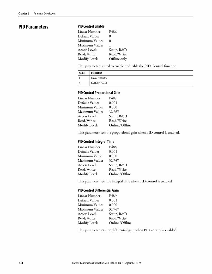
Chapter 2 Parameter Descriptions
PID Parameters PID Control EnableLinear Number: P486Default Value: 0Minimum Value: 0Maximum Value: 1Access Level: Setup, R&DRead/Write: Read/WriteModify Level: Offline only
This parameter is used to enable or disable the PID Control function.
PID Control Proportional GainLinear Number: P487Default Value: 0.001Minimum Value: 0.000Maximum Value: 32.767Access Level: Setup, R&DRead/Write: Read/WriteModify Level: Online/Offline
This parameter sets the proportional gain when PID control is enabled.
PID Control Integral TimeLinear Number: P488Default Value: 0.001Minimum Value: 0.000Maximum Value: 32.767Access Level: Setup, R&DRead/Write: Read/WriteModify Level: Online/Offline
This parameter sets the integral time when PID control is enabled.
PID Control Differential GainLinear Number: P489Default Value: 0.001Minimum Value: 0.000Maximum Value: 32.767Access Level: Setup, R&DRead/Write: Read/WriteModify Level: Online/Offline
This parameter sets the differential gain when PID control is enabled.
Value Description
0 Disable PID Control
1 Enable PID Control
134 Rockwell Automation Publication 6000-TD004E-EN-P - September 2019

Parameter Descriptions Chapter 2
PID Control Differential TimeLinear Number: P490Default Value: 0.001Minimum Value: 0.000Maximum Value: 32.767Access Level: Setup, R&DRead/Write: Read/WriteModify Level: Online/Offline
This parameter sets the differential time when PID control is enabled.
PID Control Feedback Lower LimitLinear Number: P491Default Value: 0.00Minimum Value: 0.00Maximum Value: 327.67Access Level: Setup, R&DRead/Write: Read/WriteModify Level: Offline only
This parameter sets the feedback lower limit when PID control is enabled.
PID Control Feedback Upper LimitLinear Number: P492Default Value: 1.00Minimum Value: 0.00Maximum Value: 327.67Access Level: Setup, R&DRead/Write: Read/WriteModify Level: Offline only
This parameter sets the feedback upper limit when PID control is enabled.
Deceleration Control Parameters
Deceleration Control EnableLinear Number: P396Default Value: 1Minimum Value: 0Maximum Value: 1Access Level: Setup, R&DRead/Write: Read/WriteModify Level: Online/Offline
This parameter is used to enable or disable the Deceleration Control function.
Value Description
0 Disable Deceleration Control
1 Enable Deceleration Control
Rockwell Automation Publication 6000-TD004E-EN-P - September 2019 135

Chapter 2 Parameter Descriptions
DC Bus Lower LimitLinear Number: P397Default Value: 700V (2.3/2.4 kV)
900V(4.0/4.16 kV)950V (3.0/3.3/6.3/6.6 kV)1000V (6.0/6.9/10.0/11.0 kV)
Minimum Value: 0VMaximum Value: 32767VAccess Level: Setup, R&DRead/Write: Read/WriteModify Level: Online/Offline
This parameter sets the lower limit for DC bus voltage.
DC Bus Upper LimitLinear Number: P398Default Value: 800V (2.3/2.4 kV)
1000V(4.0/4.16 kV)1050V (3.0/3.3/6.0/6.3/6.6/6.9/10.0/11.0 kV)
Minimum Value: 0VMaximum Value: 32767VAccess Level: Setup, R&DRead/Write: Read/WriteModify Level: Online/Offline
This parameter sets the upper limit for DC bus voltage.
Deceleration Iq ThresholdLinear Number: P434Default Value: 25%Minimum Value: 5%Maximum Value: 100%Access Level: Setup, R&DRead/Write: Read/WriteModify Level: Online/Offline
This parameter sets the threshold for deceleration Iq.
Deceleration Control Frequency RangeLinear Number: P435Default Value: 20%Minimum Value: 0%Maximum Value: 100%Access Level: Setup, R&DRead/Write: Read/WriteModify Level: Online/Offline
This parameter sets the frequency range for deceleration control.
136 Rockwell Automation Publication 6000-TD004E-EN-P - September 2019

Parameter Descriptions Chapter 2
Protection Parameters VFD Minimum Overload CurrentLinear Number: P079Default Value: 100.00%Minimum Value: 0.00%Maximum Value: 399.99%Access Level: Setup, R&DRead/Write: Read/WriteModify Level: Online/Offline
This parameter sets the minimum overload current for the drive.
VFD Overload CurrentLinear Number: P080Default Value: 110.00% (Frame A)
120.00% (Frame B)Minimum Value: 0.00%Maximum Value: 399.99%Access Level: Setup, R&DRead/Write: Read/WriteModify Level: Online/Offline
This parameter sets the overload current threshold for the drive.
VFD Overload TimeLinear Number: P081Default Value: 60 sMinimum Value: 0 sMaximum Value: 32767 sAccess Level: Setup, R&DRead/Write: Read/WriteModify Level: Online/Offline
This parameter sets the overload time delay for the drive.
VFD Overload Cycle TimeLinear Number: P082Default Value: 600 sMinimum Value: 0 sMaximum Value: 32767 sAccess Level: Setup, R&DRead/Write: Read/WriteModify Level: Online/Offline
This parameter sets the heating and cooling cycles for the drive.
Rockwell Automation Publication 6000-TD004E-EN-P - September 2019 137
Chapter 2 Parameter Descriptions
VFD Overload Current OffsetLinear Number: P107Default Value: 4.99%Minimum Value: 0.00%Maximum Value: 399.99%Access Level: R&DRead/Write: Read/WriteModify Level: Online/Offline
This parameter sets the overload current offset for the drive.
Motor Overload Current OffsetLinear Number: P108Default Value: 4.99%Minimum Value: 0.00%Maximum Value: 399.99%Access Level: R&DRead/Write: Read/WriteModify Level: Online/Offline
This parameter sets the overload current offset for the motor.
Heating Current ThresholdLinear Number: P110Default Value: 105.00% (Frame A)
110.00% (Frame B)Minimum Value: 0.00%Maximum Value: 399.99%Access Level: R&DRead/Write: Read/WriteModify Level: Online/Offline
This parameter sets the threshold for the drive heating current.
Line Over Voltage Fault ThresholdLinear Number: P154Default Value: 115.00%Minimum Value: 0.00%Maximum Value: 199.99%Access Level: Setup, R&DRead/Write: Read/WriteModify Level: Online/Offline
This parameter sets the threshold for the input over voltage fault.
138 Rockwell Automation Publication 6000-TD004E-EN-P - September 2019

Parameter Descriptions Chapter 2
Line Over Voltage Fault DelayLinear Number: P155Default Value: 10 msMinimum Value: 0 msMaximum Value: 32767 msAccess Level: Setup, R&DRead/Write: Read/WriteModify Level: Online/Offline
This parameter sets the delay for the input over voltage fault.
Line Under Voltage Warning ThresholdLinear Number: P156Default Value: 80%Minimum Value: 0%Maximum Value: 100%Access Level: Setup, R&DRead/Write: Read/WriteModify Level: Online/Offline
This parameter sets the threshold for the input under voltage warning.
Line Under Voltage Warning DelayLinear Number: P157Default Value: 1000 msMinimum Value: 0 msMaximum Value: 32767 msAccess Level: Setup, R&DRead/Write: Read/WriteModify Level: Online/Offline
This parameter sets the delay for the input under voltage warning.
Line Neutral Over Voltage Warning ThresholdLinear Number: P158Default Value: 60.00%Minimum Value: 0.00%Maximum Value: 199.99%Access Level: Setup, R&DRead/Write: Read/WriteModify Level: Online/Offline
This parameter sets the threshold for the ground input over voltage warning.
Rockwell Automation Publication 6000-TD004E-EN-P - September 2019 139
Chapter 2 Parameter Descriptions
Line Neutral Over Voltage Warning DelayLinear Number: P159Default Value: 1000 msMinimum Value: 0 msMaximum Value: 32767 msAccess Level: Setup, R&DRead/Write: Read/WriteModify Level: Online/Offline
This parameter sets the delay for the ground input over voltage warning.
Line Neutral Over Voltage Fault ThresholdLinear Number: P160Default Value: 80.00%Minimum Value: 0.00%Maximum Value: 199.99%Access Level: Setup, R&DRead/Write: Read/WriteModify Level: Online/Offline
This parameter sets the threshold for the ground input over voltage fault.
Line Neutral Over Voltage Fault DelayLinear Number: P161Default Value: 1000 msMinimum Value: 0 msMaximum Value: 32767 msAccess Level: Setup, R&DRead/Write: Read/WriteModify Level: Online/Offline
This parameter sets the delay for the ground input over voltage fault.
Line Voltage Positive Sequence Filter TimeLinear Number: P162Default Value: 10 msMinimum Value: 0 msMaximum Value: 32767 msAccess Level: Setup, R&DRead/Write: Read/WriteModify Level: Online/Offline
This parameter sets the time for the Line Voltage Positive Sequence Filter.
140 Rockwell Automation Publication 6000-TD004E-EN-P - September 2019

Parameter Descriptions Chapter 2
Line Voltage Negative Sequence Filter TimeLinear Number: P163Default Value: 10 msMinimum Value: 0 msMaximum Value: 32767 msAccess Level: Setup, R&DRead/Write: Read/WriteModify Level: Online/Offline
This parameter sets the time for the Line Voltage Negative Sequence Filter.
Line Voltage Negative Sequence Fault ThresholdLinear Number: P164Default Value: 20.00%Minimum Value: 0.00%Maximum Value: 199.99%Access Level: Setup, R&DRead/Write: Read/WriteModify Level: Online/Offline
This parameter sets the threshold for the Line Voltage Negative Sequence Fault.
Line Voltage Negative Sequence Fault DelayLinear Number: P165Default Value: 10 msMinimum Value: 0 msMaximum Value: 32767 msAccess Level: Setup, R&DRead/Write: Read/WriteModify Level: Online/Offline
This parameter sets the delay for the Line Voltage Negative Sequence Fault.
Line Voltage Phaser Sequence Reverse EnableLinear Number: P166Default Value: 0Minimum Value: 0Maximum Value: 1Access Level: Setup, R&DRead/Write: Read/WriteModify Level: Online/Offline
This parameter is used to enable or disable the Line Voltage Phaser Sequence Reverse function. This changes the phase direction of the input voltage. The phaser sequence is obtained from register K101. The sequence is positive if the value of K101 is positive, and vice versa. If the sequence is negative, set this parameter to “1”.
Value Description
0 Disable Line Voltage Phaser Sequence Reverse
1 Enable Line Voltage Phaser Sequence Reverse
Rockwell Automation Publication 6000-TD004E-EN-P - September 2019 141

Chapter 2 Parameter Descriptions
Line Current Filter TimeLinear Number: P168Default Value: 10 msMinimum Value: 0 msMaximum Value: 32767 msAccess Level: Setup, R&DRead/Write: Read/WriteModify Level: Online/Offline
This parameter sets the time for the Line Current Filter.
Line Short Circuit Fault ThresholdLinear Number: P169Default Value: 180%Minimum Value: 0%Maximum Value: 400%Access Level: Setup, R&DRead/Write: Read/WriteModify Level: Online/Offline
This parameter sets the threshold for the Line Short Circuit Fault.
Line Short Circuit Fault DelayLinear Number: P170Default Value: 10 msMinimum Value: 0 msMaximum Value: 32767 msAccess Level: Setup, R&DRead/Write: Read/WriteModify Level: Online/Offline
This parameter sets the delay for the Line Short Circuit Fault.
Line Current Positive Sequence Filter Time Linear Number: P174Default Value: 10 msMinimum Value: 0 msMaximum Value: 32767 msAccess Level: Setup, R&DRead/Write: Read/WriteModify Level: Online/Offline
This parameter sets the time for the Line Current Positive Sequence Filter.
142 Rockwell Automation Publication 6000-TD004E-EN-P - September 2019
Parameter Descriptions Chapter 2
Line Current Negative Sequence Filter TimeLinear Number: P175Default Value: 10 msMinimum Value: 0 msMaximum Value: 32767 msAccess Level: Setup, R&DRead/Write: Read/WriteModify Level: Online/Offline
This parameter sets the time for the Line Current Negative Sequence Filter.
Line Current Negative Sequence Fault ThresholdLinear Number: P176Default Value: 100.00%Minimum Value: 0.00%Maximum Value: 199.99%Access Level: Setup, R&DRead/Write: Read/WriteModify Level: Online/Offline
This parameter sets the threshold for the Line Current Negative Sequence Fault.
Line Current Negative Sequence Fault DelayLinear Number: P177Default Value: 10 msMinimum Value: 0 msMaximum Value: 32767 msAccess Level: Setup, R&DRead/Write: Read/WriteModify Level: Online/Offline
This parameter sets the delay for the Line Current Negative Sequence Fault.
Phase Over Current Enable Frequency Range Upper LimitLinear Number: P208Default Value: 10Minimum Value: 0Maximum Value: 100Access Level: R&DRead/Write: Read/WriteModify Level: Online/Offline
This parameter sets the upper limit for the Phase Over Current Enable Frequency Range.
Rockwell Automation Publication 6000-TD004E-EN-P - September 2019 143
Chapter 2 Parameter Descriptions
Phase Over Current Filter TimeLinear Number: P209Default Value: 5Minimum Value: 0Maximum Value: 32767Access Level: R&DRead/Write: Read/WriteModify Level: Online/Offline
This parameter sets the time for the Phase Over Current Filter.
Phase Over Current ThresholdLinear Number: P210Default Value: 179.99Minimum Value: 0.00Maximum Value: 399.99Access Level: Setup, R&DRead/Write: Read/WriteModify Level: Online/Offline
This parameter sets the threshold for the Phase Over Current.
Filter Time For Abnormal Output VoltageLinear Number: P211Default Value: 1000 msMinimum Value: 0 msMaximum Value: 32767 msAccess Level: R&DRead/Write: Read/WriteModify Level: Online/Offline
This parameter sets the filter time for the Abnormal Output Voltage.
Filter Time For Output Short-CircuitLinear Number: P212Default Value: 10 msMinimum Value: 0 msMaximum Value: 32767 msAccess Level: Setup, R&DRead/Write: Read/WriteModify Level: Online/Offline
This parameter sets the filter time for the Output Short-Circuit.
144 Rockwell Automation Publication 6000-TD004E-EN-P - September 2019
Parameter Descriptions Chapter 2
Output Short-Circuit Fault ThresholdLinear Number: P213Default Value: 179.99%Minimum Value: 0.00%Maximum Value: 399.99%Access Level: Setup, R&DRead/Write: Read/WriteModify Level: Online/Offline
This parameter sets the threshold for the Output Short-Circuit Fault.
Motor Minimum Overload CurrentLinear Number: P214Default Value: 104.99%Minimum Value: 0.00%Maximum Value: 399.99%Access Level: Setup, R&DRead/Write: Read/WriteModify Level: Online/Offline
This parameter sets the minimum over load current for the motor.
Motor Overload Cycle TimeLinear Number: P215Default Value: 600 sMinimum Value: 0 sMaximum Value: 32767 sAccess Level: Setup, R&DRead/Write: Read/WriteModify Level: Online/Offline
This parameter sets the Motor Overload Cycle Time.
Motor Overload Trip ThresholdLinear Number: P216Default Value: 120.00%Minimum Value: 0.00%Maximum Value: 399.99%Access Level: Setup, R&DRead/Write: Read/WriteModify Level: Online/Offline
This parameter sets the threshold for the Motor Overload Trip.
Rockwell Automation Publication 6000-TD004E-EN-P - September 2019 145
Chapter 2 Parameter Descriptions
Motor Overload TimeLinear Number: P217Default Value: 60 sMinimum Value: 0 sMaximum Value: 32767 sAccess Level: Setup, R&DRead/Write: Read/WriteModify Level: Online/Offline
This parameter sets the Motor Overload Time.
Filter Time For Output Over VoltageLinear Number: P221Default Value: 100 msMinimum Value: 0 ms Maximum Value: 32767 msAccess Level: R&DRead/Write: Read/WriteModify Level: Online/Offline
This parameter sets the filter time for the Output Over Voltage.
Output Over Voltage Fault ThresholdLinear Number: P222Default Value: 120.00 puMinimum Value: 0.00 puMaximum Value: 199.99 puAccess Level: Setup, R&DRead/Write: Read/WriteModify Level: Online/Offline
This parameter sets the threshold for the Output Over Voltage Fault.
Output Voltage Deviation Warning ThresholdLinear Number: P223Default Value: 60.00 puMinimum Value: 0.00 puMaximum Value: 199.99 puAccess Level: Setup, R&DRead/Write: Read/WriteModify Level: Online/Offline
This parameter sets the threshold for the Output Voltage Deviation Warning.
146 Rockwell Automation Publication 6000-TD004E-EN-P - September 2019

Parameter Descriptions Chapter 2
Output Voltage Deviation Fault ThresholdLinear Number: P224Default Value: 80.00 puMinimum Value: 0.00 puMaximum Value: 199.99 puAccess Level: Setup, R&DRead/Write: Read/WriteModify Level: Online/Offline
This parameter sets the threshold for the Output Voltage Deviation Fault.
Output Voltage Abnormality Warning Cancellation ThresholdLinear Number: P226Default Value: 50.00 puMinimum Value: 0.00 puMaximum Value: 199.99 puAccess Level: R&DRead/Write: Read/WriteModify Level: Online/Offline
This parameter sets the threshold for the Output Voltage Abnormality Warning Cancellation.
Ground Fault Detection Scaling Correction FactorLinear Number: P227Default Value: 100.00%Minimum Value: 0.00%Maximum Value: 199.99%Access Level: R&DRead/Write: Read/WriteModify Level: Online/Offline
This parameter sets the Ground Fault Detection Scaling Correction Factor.
Filter Time For Ground FaultLinear Number: P228Default Value: 1000 msMinimum Value: 0 msMaximum Value: 32767msAccess Level: R&DRead/Write: Read/WriteModify Level: Online/Offline
This parameter sets the filter time for the Ground Fault.
Rockwell Automation Publication 6000-TD004E-EN-P - September 2019 147

Chapter 2 Parameter Descriptions
Ground Fault Warning ThresholdLinear Number: P229Default Value: 8.00 puMinimum Value: 0.00 puMaximum Value: 199.99Access Level: R&DRead/Write: Read/WriteModify Level: Online/Offline
This parameter sets the threshold for the Ground Fault Warning.
Ground Fault Trip ThresholdLinear Number: P230Default Value: 15.00 puMinimum Value: 0.00 puMaximum Value: 199.99 puAccess Level: R&DRead/Write: Read/WriteModify Level: Online/Offline
This parameter sets the threshold for the Ground Fault Trip.
Filter Time For Overspeed Fault (Upper Limit)Linear Number: P231Default Value: 100Minimum Value: 0Maximum Value: 32767Access Level: R&DRead/Write: Read/WriteModify Level: Online/Offline
This parameter sets the upper limit for Filter Time For Overspeed Fault. Overspeed occurs when speed is greater than Threshold Of Over-Speed Fault At Upper Frequency Limit (P234).
Filter Time For Overspeed Fault (Lower Limit)Linear Number: P232Default Value: 100Minimum Value: 0Maximum Value: 32767Access Level: R&DRead/Write: Read/WriteModify Level: Online/Offline
This parameter sets the lower limit for Filter Time For Overspeed Fault. Overspeed occurs when speed is greater than Threshold Of Over-Speed Fault At Lower Frequency Limit (P233).
148 Rockwell Automation Publication 6000-TD004E-EN-P - September 2019

Parameter Descriptions Chapter 2
Threshold Of Over-Speed Fault At Lower Frequency LimitLinear Number: P233Default Value: 20.00 puMinimum Value: 0.00 puMaximum Value: 199.99 puAccess Level: R&DRead/Write: Read/WriteModify Level: Online/Offline
This parameter sets the Threshold Of Over-Speed Fault At Lower Frequency Limit.
Threshold Of Over-Speed Fault At Upper Frequency LimitLinear Number: P234Default Value: 20.00 puMinimum Value: 0.00 puMaximum Value: 199.99 puAccess Level: R&DRead/Write: Read/WriteModify Level: Online/Offline
This parameter sets the Threshold of Over-Speed Fault At Upper Frequency Limit.
Frequency Deviation Warning Cancellation ThresholdLinear Number: P235Default Value: 0.99 puMinimum Value: 0.00 puMaximum Value: 199.99 puAccess Level: R&DRead/Write: Read/WriteModify Level: Online/Offline
This parameter sets the threshold for the Frequency Deviation Warning Cancellation.
Frequency Deviation Warning ThresholdLinear Number: P236Default Value: 6.00 puMinimum Value: 0.00 puMaximum Value: 199.99Access Level: R&DRead/Write: Read/WriteModify Level: Online/Offline
This parameter sets the threshold for the Frequency Deviation Warning.
Rockwell Automation Publication 6000-TD004E-EN-P - September 2019 149
Chapter 2 Parameter Descriptions
Frequency Deviation Warning DelayLinear Number: P237Default Value: 8 msMinimum Value: 0 ms Maximum Value: 32767 msAccess Level: R&DRead/Write: Read/WriteModify Level: Online/Offline
This parameter sets the delay for the Frequency Deviation Warning.
Motor Stall Fault ThresholdLinear Number: P238Default Value: 10.00 puMinimum Value: 0.00 puMaximum Value: 199.99 puAccess Level: Setup, R&DRead/Write: Read/WriteModify Level: Online/Offline
This parameter sets the threshold for the Motor Stall Fault.
Motor Stall Fault DelayLinear Number: P239Default Value: 6000 msMinimum Value: 0 msMaximum Value: 32767 msAccess Level: R&DRead/Write: Read/WriteModify Level: Online/Offline
This parameter sets the delay for the Motor Stall Fault.
Transformer Over Temperature Fault DelayLinear Number: P240Default Value: 10 msMinimum Value: 0 msMaximum Value: 32767 msAccess Level: R&DRead/Write: Read/WriteModify Level: Online/Offline
This parameter sets the delay for the Transformer Over Temperature Fault.
150 Rockwell Automation Publication 6000-TD004E-EN-P - September 2019
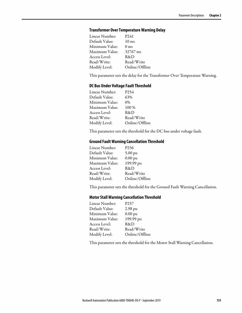
Parameter Descriptions Chapter 2
Transformer Over Temperature Warning DelayLinear Number: P241Default Value: 10 msMinimum Value: 0 msMaximum Value: 32767 msAccess Level: R&DRead/Write: Read/WriteModify Level: Online/Offline
This parameter sets the delay for the Transformer Over Temperature Warning.
DC Bus Under Voltage Fault ThresholdLinear Number: P254Default Value: 63%Minimum Value: 0%Maximum Value: 100 %Access Level: R&DRead/Write: Read/WriteModify Level: Online/Offline
This parameter sets the threshold for the DC bus under voltage fault.
Ground Fault Warning Cancellation ThresholdLinear Number: P256Default Value: 5.00 puMinimum Value: 0.00 puMaximum Value: 199.99 puAccess Level: R&DRead/Write: Read/WriteModify Level: Online/Offline
This parameter sets the threshold for the Ground Fault Warning Cancellation.
Motor Stall Warning Cancellation ThresholdLinear Number: P257Default Value: 2.98 puMinimum Value: 0.00 puMaximum Value: 199.99 puAccess Level: R&DRead/Write: Read/WriteModify Level: Online/Offline
This parameter sets the threshold for the Motor Stall Warning Cancellation.
Rockwell Automation Publication 6000-TD004E-EN-P - September 2019 151
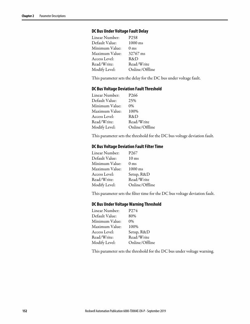
Chapter 2 Parameter Descriptions
DC Bus Under Voltage Fault DelayLinear Number: P258Default Value: 1000 msMinimum Value: 0 msMaximum Value: 32767 msAccess Level: R&DRead/Write: Read/WriteModify Level: Online/Offline
This parameter sets the delay for the DC bus under voltage fault.
DC Bus Voltage Deviation Fault ThresholdLinear Number: P266Default Value: 25%Minimum Value: 0%Maximum Value: 100%Access Level: R&DRead/Write: Read/WriteModify Level: Online/Offline
This parameter sets the threshold for the DC bus voltage deviation fault.
DC Bus Voltage Deviation Fault Filter TimeLinear Number: P267Default Value: 10 msMinimum Value: 0 msMaximum Value: 1000 msAccess Level: Setup, R&DRead/Write: Read/WriteModify Level: Online/Offline
This parameter sets the filter time for the DC bus voltage deviation fault.
DC Bus Under Voltage Warning ThresholdLinear Number: P274Default Value: 80%Minimum Value: 0%Maximum Value: 100%Access Level: Setup, R&DRead/Write: Read/WriteModify Level: Online/Offline
This parameter sets the threshold for the DC bus under voltage warning.
152 Rockwell Automation Publication 6000-TD004E-EN-P - September 2019
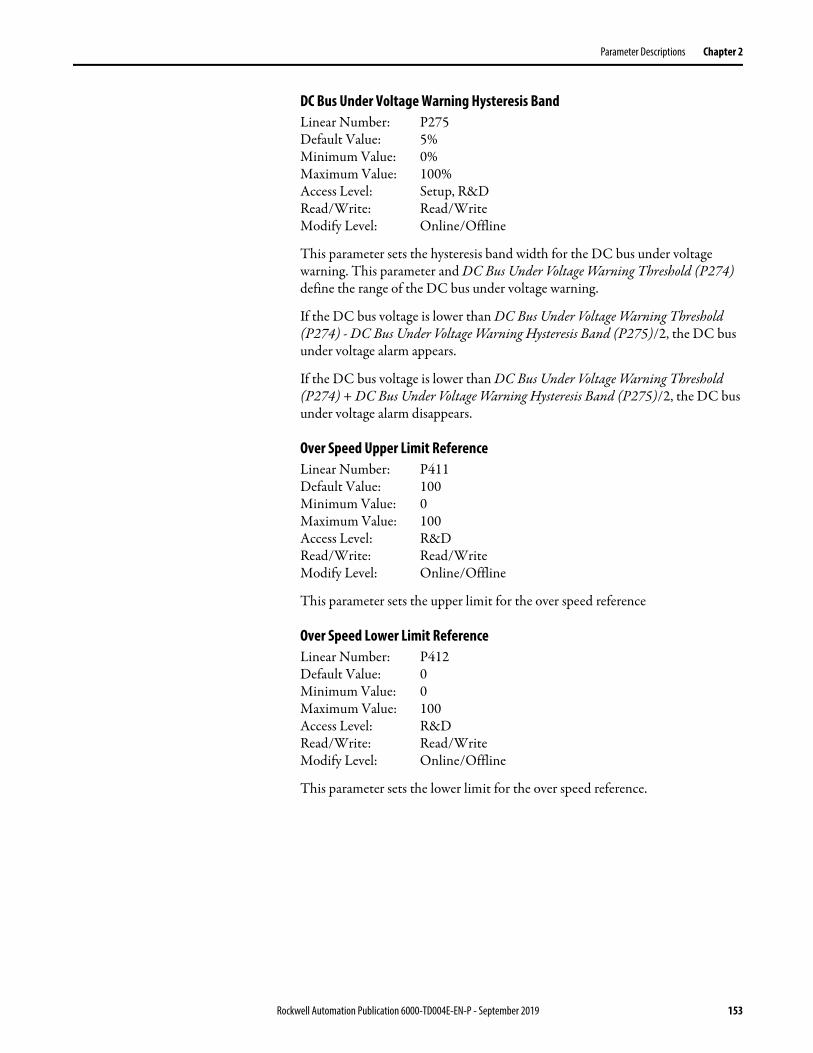
Parameter Descriptions Chapter 2
DC Bus Under Voltage Warning Hysteresis BandLinear Number: P275Default Value: 5%Minimum Value: 0%Maximum Value: 100%Access Level: Setup, R&DRead/Write: Read/WriteModify Level: Online/Offline
This parameter sets the hysteresis band width for the DC bus under voltage warning. This parameter and DC Bus Under Voltage Warning Threshold (P274) define the range of the DC bus under voltage warning.
If the DC bus voltage is lower than DC Bus Under Voltage Warning Threshold (P274) - DC Bus Under Voltage Warning Hysteresis Band (P275)/2, the DC bus under voltage alarm appears.
If the DC bus voltage is lower than DC Bus Under Voltage Warning Threshold (P274) + DC Bus Under Voltage Warning Hysteresis Band (P275)/2, the DC bus under voltage alarm disappears.
Over Speed Upper Limit ReferenceLinear Number: P411Default Value: 100Minimum Value: 0Maximum Value: 100Access Level: R&DRead/Write: Read/WriteModify Level: Online/Offline
This parameter sets the upper limit for the over speed reference
Over Speed Lower Limit ReferenceLinear Number: P412Default Value: 0Minimum Value: 0Maximum Value: 100Access Level: R&DRead/Write: Read/WriteModify Level: Online/Offline
This parameter sets the lower limit for the over speed reference.
Rockwell Automation Publication 6000-TD004E-EN-P - September 2019 153

Chapter 2 Parameter Descriptions
Para
met
ers L
isted
by G
roup
Cont
rol O
wne
r Par
amet
ers
Nam
epla
te Pa
ram
eter
s
No.
Nam
eM
in.
Max
.De
faul
t Val
ues
Units
Mod
ify
Root
Acce
ss
2300
V24
00V
3000
V33
00V
4000
V41
60V
6000
V63
00V
6600
V69
00V
1000
0V11
000V
US
R
P475
Owne
r #1 S
electi
on0
10
00
00
00
00
00
0On
/Off
YY
P476
Owne
r #2 S
electi
on2
238
88
88
88
88
88
8On
/Off
YY
P477
Owne
r #3 S
electi
on18
2323
2323
2323
2323
2323
2323
23On
/Off
YY
P478
Loca
l/Rem
ote O
wner
Selec
tion
03
00
00
00
00
00
00
Offli
neY
Y
P480
4-St
ep Va
riabl
e Spe
ed –
Spee
d10
7510
1010
1010
1010
1010
1010
10On
/Off
YY
P481
4-St
ep Va
riabl
e Spe
ed –
Spee
d20
7520
2020
2020
2020
2020
2020
20On
/Off
YY
P482
4-St
ep Va
riabl
e Spe
ed –
Spee
d30
7530
3030
3030
3030
3030
3030
30On
/Off
YY
P483
4-St
ep Va
riabl
e Spe
ed –
Spee
d40
7540
4040
4040
4040
4040
4040
40On
/Off
YY
P485
Whe
n Disc
onne
cted B
etwe
en D
CS an
d PL
C0
51
11
11
11
11
11
1On
/Off
YY
No.
Nam
eM
in.
Max
.De
faul
t Val
ues
Units
Mod
ify
Root
Acce
ss
2300
V24
00V
3000
V33
00V
4000
V41
60V
6000
V63
00V
6600
V69
00V
1000
0V11
000V
US
R
P007
Num
ber o
f Pow
er Ce
lls Pe
r Pha
se0
93
33
34
45
66
68
9Of
fline
YY
P011
Powe
r Cell
DC B
us Ra
ted V
oltag
e50
1300
650
650
920
920
848
848
976
920
920
976
976
976
VOf
fline
YY
P012
Mot
or Ra
ted V
oltag
e0
3276
723
0024
0030
0033
0040
0041
6060
0063
0066
0069
0010
000
1100
0V
Offli
neY
Y
P013
Mot
or Ra
ted P
ower
032
767
00
00
00
00
00
00
kWOf
fline
YY
P014
Mot
or Ra
ted S
peed
050
0015
0015
0015
0015
0015
0015
0015
0015
0015
0015
0015
0015
00RP
MOf
fline
YY
P015
Mot
or Ra
ted P
ower
Facto
r0
100
87.99
87.99
87.99
87.99
87.99
87.99
87.99
87.99
87.99
87.99
87.99
87.99
%Of
fline
YY
P017
Num
ber o
f Mot
or Po
le Pa
irs0
100
22
22
22
22
22
22
Offli
neY
P019
Enco
der R
esolu
tion
040
9610
2410
2410
2410
2410
2410
2410
2410
2410
2410
2410
2410
24Of
fline
Y
P085
VFD
Rate
d Cur
rent
050
0040
4040
4040
4040
4040
4040
40Of
fline
YY
P146
Line R
ated
Volta
ge0
3276
723
0024
0030
0033
0040
0041
6060
0063
0066
0069
0010
000
1100
0V
On/O
ffY
Y
P147
Line R
ated
Freq
uenc
y0
3276
750
5050
5050
5050
5050
5050
50Hz
On/O
ffY
Y
P148
Trans
form
er Ra
ted P
ower
032
767
00
00
00
00
00
00
kVA
On/O
ffY
Y
154 Rockwell Automation Publication 6000-TD004E-EN-P - September 2019

Parameter Descriptions Chapter 2
Othe
r Par
amet
ers
HMI D
ispla
y Par
amet
ers
P149
Trans
form
er Sh
ort C
ircuit
Impe
danc
e0
100
55
55
55
55
55
55
%On
/Off
YY
P195
Line C
T Rat
io0
00
00
00
00
00
00
0Of
fline
YY
P196
Line C
T Bur
den R
esist
or0
00
00
00
00
00
00
0Of
fline
YY
P197
Mot
or H
ECS R
atio
099
99.99
1000
.0010
00.00
1000
.0010
00.00
1000
.0010
00.00
1000
.0010
00.00
1000
.0010
00.00
1000
.0010
00.00
Offli
neY
YY
P198
Mot
or H
ECS B
urde
n Res
istor
019
.9915
1515
1515
1515
1515
1515
15Of
fline
YY
Y
P199
Mot
or Ra
ted C
urre
nt0
5000
4040
4040
4040
4040
4040
4040
AOf
fline
YY
Y
P277
DC Li
nk Vo
ltage
Sag S
calin
g At R
ated
Lo
ad0
100
55
55
55
55
55
55
AOn
/Off
Y
No.
Nam
eM
in.
Max
.De
faul
t Val
ues
Units
Mod
ify
Root
Acce
ss
2300
V24
00V
3000
V33
00V
4000
V41
60V
6000
V63
00V
6600
V69
00V
1000
0V11
000V
US
R
No.
Nam
eM
in.
Max
.De
faul
t Val
ues
Units
Mod
ify
Root
Acce
ss
2300
V24
00V
3000
V33
00V
4000
V41
60V
6000
V63
00V
6600
V69
00V
1000
0V11
000V
US
R
P040
Safe
Star
t Con
dition
01
11
11
11
11
11
11
Offli
neY
Y
P250
Inpu
t Con
tacto
r/Circ
uit Br
eake
r Clos
e De
lay0
3276
720
000
2000
020
000
2000
020
000
2000
020
000
2000
020
000
2000
020
000
2000
0m
sOn
/Off
Y
P494
User
Analo
g Set
-poin
t Swi
tch0
30
00
00
00
00
00
0On
/Off
YY
No.
Nam
eM
in.
Max
.De
faul
t Val
ues
Units
Mod
ify
Root
Acce
ss
2300
V24
00V
3000
V33
00V
4000
V41
60V
6000
V63
00V
6600
V69
00V
1000
0V11
000V
US
R
P351
Rate
d Fre
quen
cy H
MI D
isplay
Filte
r Tim
e0
3276
710
010
010
010
010
010
010
010
010
010
010
010
0m
sOn
/Off
Y
P352
Rate
d Fre
quen
cy H
MI D
isplay
Inte
ger
Part
075
5050
5050
5050
5050
5050
5050
On/O
ffY
YY
P353
Rate
d Fre
quen
cy H
MI D
isplay
Dec
imal
Part
010
000
00
00
00
00
00
0On
/Off
Y
P354
Mot
or Vo
ltage
HM
I Disp
lay Fi
lter T
ime
032
767
2000
2000
2000
2000
2000
2000
2000
2000
2000
2000
2000
2000
ms
On/O
ffY
P355
Mot
or Vo
ltage
HM
I Disp
lay In
tege
r Par
t0
1638
423
0024
0030
0033
0040
0041
6060
0063
0066
0069
0010
000
1100
0On
/Off
YY
Y
P356
Mot
or Vo
ltage
HM
I Disp
lay D
ecim
al Pa
rt0
1000
00
00
00
00
00
00
On/O
ffY
P357
Actu
al Fre
quen
cy H
MI D
isplay
Filte
r Tim
e0
3276
710
010
010
010
010
010
010
010
010
010
010
010
0m
sOn
/Off
Y
P358
Actu
al Fre
quen
cy H
MI D
isplay
Inte
ger
Part
075
5050
5050
5050
5050
5050
5050
On/O
ffY
YY
Rockwell Automation Publication 6000-TD004E-EN-P - September 2019 155
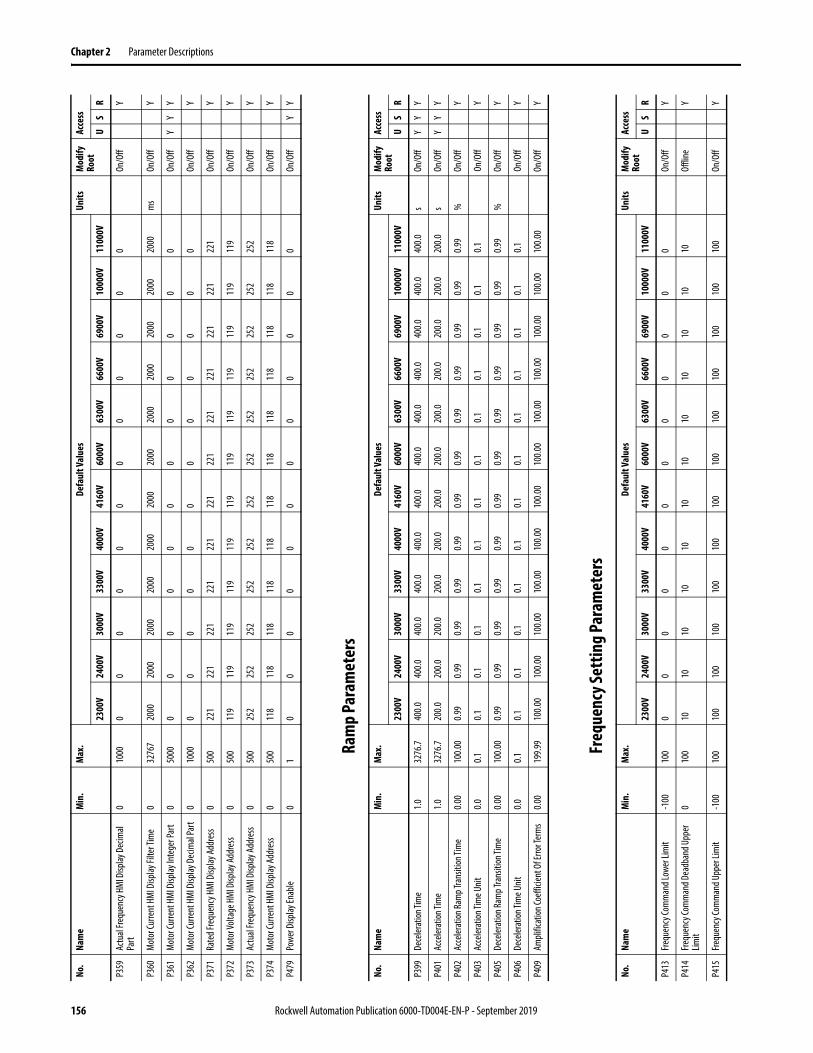
Chapter 2 Parameter Descriptions
Ram
p Pa
ram
eter
s
Freq
uenc
y Set
ting
Para
met
ers
P359
Actu
al Fre
quen
cy H
MI D
isplay
Dec
imal
Part
010
000
00
00
00
00
00
0On
/Off
Y
P360
Mot
or Cu
rrent
HM
I Disp
lay Fi
lter T
ime
032
767
2000
2000
2000
2000
2000
2000
2000
2000
2000
2000
2000
2000
ms
On/O
ffY
P361
Mot
or Cu
rrent
HM
I Disp
lay In
tege
r Par
t0
5000
00
00
00
00
00
00
On/O
ffY
YY
P362
Mot
or Cu
rrent
HM
I Disp
lay D
ecim
al Pa
rt0
1000
00
00
00
00
00
00
On/O
ffY
P371
Rate
d Fre
quen
cy H
MI D
isplay
Addr
ess
050
022
122
122
122
122
122
122
122
122
122
122
122
1On
/Off
Y
P372
Mot
or Vo
ltage
HM
I Disp
lay Ad
dres
s0
500
119
119
119
119
119
119
119
119
119
119
119
119
On/O
ffY
P373
Actu
al Fre
quen
cy H
MI D
isplay
Addr
ess
050
025
225
225
225
225
225
225
225
225
225
225
225
2On
/Off
Y
P374
Mot
or Cu
rrent
HM
I Disp
lay Ad
dres
s0
500
118
118
118
118
118
118
118
118
118
118
118
118
On/O
ffY
P479
Powe
r Disp
lay En
able
01
00
00
00
00
00
00
On/O
ffY
Y
No.
Nam
eM
in.
Max
.De
faul
t Val
ues
Units
Mod
ify
Root
Acce
ss
2300
V24
00V
3000
V33
00V
4000
V41
60V
6000
V63
00V
6600
V69
00V
1000
0V11
000V
US
R
No.
Nam
eM
in.
Max
.De
faul
t Val
ues
Units
Mod
ify
Root
Acce
ss
2300
V24
00V
3000
V33
00V
4000
V41
60V
6000
V63
00V
6600
V69
00V
1000
0V11
000V
US
R
P399
Dece
lerat
ion Ti
me
1.032
76.7
400.0
400.0
400.0
400.0
400.0
400.0
400.0
400.0
400.0
400.0
400.0
400.0
sOn
/Off
YY
Y
P401
Acce
lerat
ion Ti
me
1.032
76.7
200.0
200.0
200.0
200.0
200.0
200.0
200.0
200.0
200.0
200.0
200.0
200.0
sOn
/Off
YY
Y
P402
Acce
lerat
ion Ra
mp T
rans
ition
Tim
e0.0
010
0.00
0.99
0.99
0.99
0.99
0.99
0.99
0.99
0.99
0.99
0.99
0.99
0.99
%On
/Off
Y
P403
Acce
lerat
ion Ti
me U
nit
0.00.1
0.10.1
0.10.1
0.10.1
0.10.1
0.10.1
0.10.1
On/O
ffY
P405
Dece
lerat
ion Ra
mp T
rans
ition
Tim
e0.0
010
0.00
0.99
0.99
0.99
0.99
0.99
0.99
0.99
0.99
0.99
0.99
0.99
0.99
%On
/Off
Y
P406
Dece
lerat
ion Ti
me U
nit0.0
0.10.1
0.10.1
0.10.1
0.10.1
0.10.1
0.10.1
0.1On
/Off
Y
P409
Ampl
ifica
tion C
oeffi
cient
Of E
rror T
erm
s0.0
019
9.99
100.0
010
0.00
100.0
010
0.00
100.0
010
0.00
100.0
010
0.00
100.0
010
0.00
100.0
010
0.00
On/O
ffY
No.
Nam
eM
in.
Max
.De
faul
t Val
ues
Units
Mod
ify
Root
Acce
ss
2300
V24
00V
3000
V33
00V
4000
V41
60V
6000
V63
00V
6600
V69
00V
1000
0V11
000V
US
R
P413
Frequ
ency
Com
man
d Low
er Li
mit
-100
100
00
00
00
00
00
00
On/O
ffY
P414
Frequ
ency
Com
man
d Dea
dban
d Upp
er
Limit
010
010
1010
1010
1010
1010
1010
10Of
fline
Y
P415
Frequ
ency
Com
man
d Upp
er Li
mit
-100
100
100
100
100
100
100
100
100
100
100
100
100
100
On/O
ffY
156 Rockwell Automation Publication 6000-TD004E-EN-P - September 2019

Parameter Descriptions Chapter 2
Stop
Mod
e Par
amet
ers
Mot
or D
irect
ion
Cont
rol P
aram
eter
s
Switc
h Fr
eque
ncy S
ettin
g Pa
ram
eter
s
P460
Rate
d Out
put F
requ
ency
075
5050
5050
5050
5050
5050
5050
Offli
neY
Y
P466
Max
imum
Out
put F
requ
ency
075
5050
5050
5050
5050
5050
5050
Offli
neY
Y
P467
Over
Spee
d Ena
ble
01
00
00
00
00
00
00
Offli
neY
Y
No.
Nam
eM
in.
Max
.De
faul
t Val
ues
Units
Mod
ify
Root
Acce
ss
2300
V24
00V
3000
V33
00V
4000
V41
60V
6000
V63
00V
6600
V69
00V
1000
0V11
000V
US
R
No.
Nam
eM
in.
Max
.De
faul
t Val
ues
Units
Mod
ify
Root
Acce
ss
2300
V24
00V
3000
V33
00V
4000
V41
60V
6000
V63
00V
6600
V69
00V
1000
0V11
000V
US
R
P024
Stop
Met
hod
01
00
00
00
00
00
00
On/O
ffY
Y
P251
Frequ
ency
Com
man
d-Lo
w Fre
quen
cy
Regio
n Bou
ndar
y0.0
100.0
0.50.5
0.50.5
0.50.5
0.50.5
0.50.5
0.50.5
On/O
ffY
P252
Mot
or In
Stop
ping C
ondit
ion Th
resh
old0
100
11
11
11
11
11
11
On/O
ffY
Y
P253
Mot
or Co
ast S
top T
ime
010
000
1010
1010
1010
1010
1010
1010
On/O
ffY
Y
P270
Delay
ed Lo
ckou
t Tim
e of S
top O
pera
tion
050
0020
0020
0020
0020
0020
0020
0020
0020
0020
0020
0020
0020
00m
sOn
/Off
Y
No.
Nam
eM
in.
Max
.De
faul
t Val
ues
Units
Mod
ify
Root
Acce
ss
2300
V24
00V
3000
V33
00V
4000
V41
60V
6000
V63
00V
6600
V69
00V
1000
0V11
000V
US
R
P008
Mot
or Ro
tatio
n Dire
ction
Und
er Lo
cal
Cont
rol
01
11
11
11
11
11
11
Offli
neY
Y
P009
Mot
or Ro
tatio
n Dire
ction
Com
man
d Se
lectio
n0
10
00
00
00
00
00
0Of
fline
YY
No.
Nam
eM
in.
Max
.De
faul
t Val
ues
Units
Mod
ify
Root
Acce
ss
2300
V24
00V
3000
V33
00V
4000
V41
60V
6000
V63
00V
6600
V69
00V
1000
0V11
000V
US
R
P087
Switc
h Fre
quen
cy Se
tting
Enab
le Co
de0
10
00
00
00
00
00
0Of
fline
Y
P088
Switc
h Fre
quen
cy Se
tting
01
00
00
00
00
00
00
Offli
neY
Rockwell Automation Publication 6000-TD004E-EN-P - September 2019 157

Chapter 2 Parameter Descriptions
VF Cu
rve S
ettin
g Pa
ram
eter
sNo
.Na
me
Min
.M
ax.
Defa
ult V
alue
sUn
itsM
odify
Ro
otAc
cess
2300
V24
00V
3000
V33
00V
4000
V41
60V
6000
V63
00V
6600
V69
00V
1000
0V11
000V
US
R
P111
Slip C
ompe
nsat
ion En
able
01
00
00
00
00
00
00
On/O
ffY
P271
Flux D
elay
050
0050
050
050
050
050
050
050
050
050
050
050
050
0m
sOn
/Off
Y
P291
SVC L
ow Fr
eque
ncy A
ccele
ratio
n Tim
e En
able
Frequ
ency
Rang
e Upp
er Li
mit
010
010
1010
1010
1010
1010
1010
10%
On/O
ffY
P292
SVC L
ow Fr
eque
ncy A
ccele
ratio
n Tim
e1
3276
.75
55
55
55
55
55
5s
On/O
ffY
P293
SVC F
lux Vo
ltage
Boos
t Coe
fficie
nt0
500
300
300
300
300
300
300
300
300
300
300
300
300
%On
/Off
Y
P294
SVC F
lux Vo
ltage
Boos
t Upp
er Fr
eque
ncy
010
010
1010
1010
1010
1010
1010
10%
On/O
ffY
P295
Iq Fi
lter T
ime F
or Sl
ip Es
timat
ion0
1000
100
100
100
100
100
100
100
100
100
100
100
100
On/O
ffY
P375
Frequ
ency
At Fi
rst Po
int fo
r 5 Po
int VF
0.00
10.00
0.99
0.99
0.99
0.99
0.99
0.99
0.99
0.99
0.99
0.99
0.99
0.99
%Of
fline
YY
P376
Ampl
itude
At Fi
rst Po
int fo
r 5 Po
int VF
0.00
3.00
0.99
0.99
0.99
0.99
0.99
0.99
0.99
0.99
0.99
0.99
0.99
0.99
%Of
fline
YY
P377
Frequ
ency
At Se
cond
Point
for 5
Point
VF10
100
2020
2020
2020
2020
2020
2020
%Of
fline
YY
Y
P378
Ampl
itude
At Se
cond
Point
for 5
Point
VF0
100
1010
1010
1010
1010
1010
1010
%Of
fline
YY
Y
P379
Frequ
ency
At Th
ird Po
int fo
r 5 Po
int VF
1010
040
4040
4040
4040
4040
4040
40%
Offli
neY
Y
P380
Ampl
itude
At Th
ird Po
int fo
r 5 Po
int VF
010
027
2727
2727
2727
2727
2727
27%
Offli
neY
Y
P381
Frequ
ency
At Fo
urth
Point
for 5
Point
VF10
100
6060
6060
6060
6060
6060
6060
%Of
fline
YY
P382
Ampl
itude
At Fo
urth
Point
for 5
Point
VF0
100
4545
4545
4545
4545
4545
4545
%Of
fline
YY
P383
Frequ
ency
At Fi
fth Po
int fo
r 5 Po
int VF
1010
080
8080
8080
8080
8080
8080
80%
Offli
neY
P384
Ampl
itude
At Fi
fth Po
int fo
r 5 Po
int VF
010
070
7070
7070
7070
7070
7070
70%
Offli
neY
Y
P451
Low
Spee
d Volt
age C
ompe
nsat
ion0
31
11
11
11
11
11
1%
Offli
neY
Y
P452
Low
Spee
d Volt
age C
ompe
nsat
ion
Frequ
ency
Thre
shold
010
020
2020
2020
2020
2020
2020
20On
/Off
YY
P453
V/F C
urve
05
55
55
55
55
55
55
Offli
neY
Y
P454
Flux T
ime
010
22
22
22
22
22
2s
Offli
neY
P455
Mod
ulat
ion In
dex
0.011
0.084
.087
.677
.385
.083
.887
.087
.081
.085
.083
.791
.089
.0On
/Off
YY
P456
Mot
or Vo
ltage
Upp
er Li
mit
0.00
110.0
84.0
87.6
77.3
85.0
83.8
87.0
87.0
81.0
85.0
83.7
91.0
89.0
On/O
ffY
Y
P458
Coef
ficien
t A0
100
4040
4040
4040
4040
4040
4040
Offli
neY
158 Rockwell Automation Publication 6000-TD004E-EN-P - September 2019
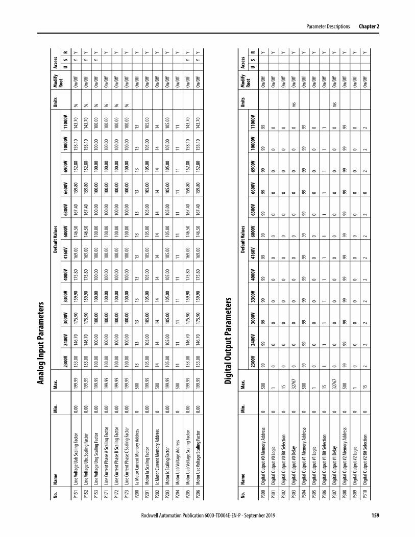
Parameter Descriptions Chapter 2
Anal
og In
put P
aram
eter
s
Digi
tal O
utpu
t Par
amet
ers
No.
Nam
eM
in.
Max
.De
faul
t Val
ues
Units
Mod
ify
Root
Acce
ss
2300
V24
00V
3000
V33
00V
4000
V41
60V
6000
V63
00V
6600
V69
00V
1000
0V11
000V
US
R
P151
Line V
oltag
e Uab
Scali
ng Fa
ctor
0.00
199.9
915
3.00
146.7
017
5.90
159.9
017
5.80
169.0
014
6.50
167.4
015
9.80
152.8
015
8.10
143.7
0%
On/O
ffY
Y
P152
Line V
oltag
e Ubc
Scali
ng Fa
ctor
0.00
199.9
915
3.00
146.7
017
5.90
159.9
017
5.80
169.0
014
6.50
167.4
015
9.80
152.8
015
8.10
143.7
0%
On/O
ffY
Y
P153
Line V
oltag
e Ung
Scali
ng Fa
ctor
0.00
199.9
910
0.00
100.0
010
0.00
100.0
010
0.00
100.0
010
0.00
100.0
010
0.00
100.0
010
0.00
100.0
0%
On/O
ffY
Y
P171
Line C
urre
nt Ph
ase A
Scali
ng Fa
ctor
0.00
199.9
910
0.00
100.0
010
0.00
100.0
010
0.00
100.0
010
0.00
100.0
010
0.00
100.0
010
0.00
100.0
0%
On/O
ffY
P172
Line C
urre
nt Ph
ase B
Scali
ng Fa
ctor
0.00
199.9
910
0.00
100.0
010
0.00
100.0
010
0.00
100.0
010
0.00
100.0
010
0.00
100.0
010
0.00
100.0
0%
On/O
ffY
P173
Line C
urre
nt Ph
ase C
Scali
ng Fa
ctor
0.00
199.9
910
0.00
100.0
010
0.00
100.0
010
0.00
100.0
010
0.00
100.0
010
0.00
100.0
010
0.00
100.0
0%
On/O
ffY
P200
Ia M
otor
Curre
nt M
emor
y Add
ress
050
013
1313
1313
1313
1313
1313
13On
/Off
Y
P201
Mot
or Ia
Scali
ng Fa
ctor
0.00
199.9
910
5.00
105.0
010
5.00
105.0
010
5.00
105.0
010
5.00
105.0
010
5.00
105.0
010
5.00
105.0
0On
/Off
Y
P202
Ic M
otor
Curre
nt M
emor
y Add
ress
050
014
1414
1414
1414
1414
1414
14On
/Off
Y
P203
Mot
or Ic
Scali
ng Fa
ctor
0.00
199.9
910
5.00
105.0
010
5.00
105.0
010
5.00
105.0
010
5.00
105.0
010
5.00
105.0
010
5.00
105.0
0On
/Off
Y
P204
Mot
or U
ab Vo
ltage
Addr
ess
050
011
1111
1111
1111
1111
1111
11On
/Off
Y
P205
Mot
or U
ab Vo
ltage
Scali
ng Fa
ctor
0.00
199.9
915
3.00
146.7
017
5.90
159.9
017
5.80
169.0
014
6.50
167.4
015
9.80
152.8
015
8.10
143.7
0On
/Off
YY
P206
Mot
or U
ac Vo
ltage
Scali
ng Fa
ctor
0.00
199.9
915
3.00
146.7
017
5.90
159.9
017
5.80
169.0
014
6.50
167.4
015
9.80
152.8
015
8.10
143.7
0On
/Off
YY
No.
Nam
eM
in.
Max
.De
faul
t Val
ues
Units
Mod
ify
Root
Acce
ss
2300
V24
00V
3000
V33
00V
4000
V41
60V
6000
V63
00V
6600
V69
00V
1000
0V11
000V
US
R
P300
Digit
al Ou
tput
#0 M
emor
y Add
ress
050
099
9999
9999
9999
9999
9999
99On
/Off
Y
P301
Digit
al Ou
tput
#0 Lo
gic0
10
00
00
00
00
00
0On
/Off
Y
P302
Digit
al Ou
tput
#0 Bi
t Sele
ction
015
00
00
00
00
00
00
On/O
ffY
P303
Digit
al Ou
tput
#0 D
elay
032
767
00
00
00
00
00
00
ms
On/O
ffY
P304
Digit
al Ou
tput
#1 M
emor
y Add
ress
050
099
9999
9999
9999
9999
9999
99On
/Off
Y
P305
Digit
al Ou
tput
#1 Lo
gic0
10
00
00
00
00
00
0On
/Off
Y
P306
Digit
al Ou
tput
#1 Bi
t Sele
ction
015
11
11
11
11
11
11
On/O
ffY
P307
Digit
al Ou
tput
#1 D
elay
032
767
00
00
00
00
00
00
ms
On/O
ffY
P308
Digit
al Ou
tput
#2 M
emor
y Add
ress
050
099
9999
9999
9999
9999
9999
99On
/Off
Y
P309
Digit
al Ou
tput
#2 Lo
gic0
10
00
00
00
00
00
0On
/Off
Y
P310
Digit
al Ou
tput
#2 Bi
t Sele
ction
015
22
22
22
22
02
22
On/O
ffY
Rockwell Automation Publication 6000-TD004E-EN-P - September 2019 159
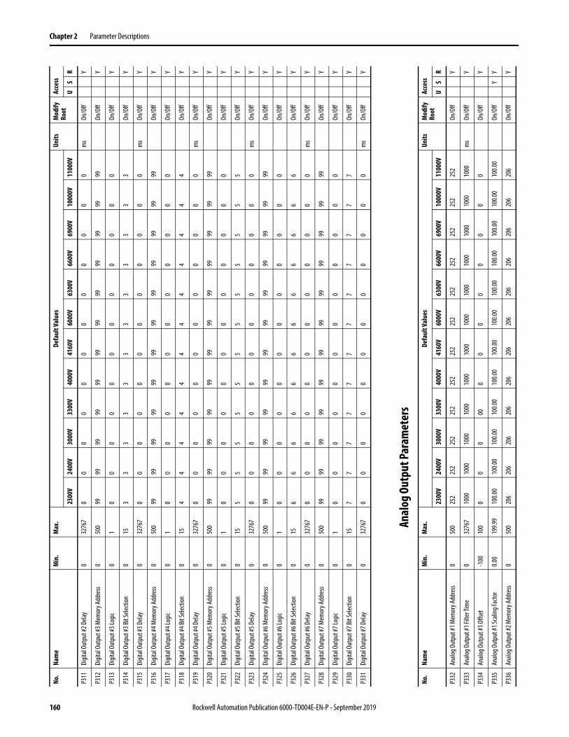
Chapter 2 Parameter Descriptions
Anal
og O
utpu
t Par
amet
ers
P311
Digit
al Ou
tput
#2 D
elay
032
767
00
00
00
00
00
00
ms
On/O
ffY
P312
Digit
al Ou
tput
#3 M
emor
y Add
ress
050
099
9999
9999
9999
9999
9999
99On
/Off
Y
P313
Digit
al Ou
tput
#3 Lo
gic0
10
00
00
00
00
00
0On
/Off
Y
P314
Digit
al Ou
tput
#3 Bi
t Sele
ction
015
33
33
33
33
33
33
On/O
ffY
P315
Digit
al Ou
tput
#3 D
elay
032
767
00
00
00
00
00
00
ms
On/O
ffY
P316
Digit
al Ou
tput
#4 M
emor
y Add
ress
050
099
9999
9999
9999
9999
9999
99On
/Off
Y
P317
Digit
al Ou
tput
#4 Lo
gic0
10
00
00
00
00
00
0On
/Off
Y
P318
Digit
al Ou
tput
#4 Bi
t Sele
ction
015
44
44
44
44
44
44
On/O
ffY
P319
Digit
al Ou
tput
#4 D
elay
032
767
00
00
00
00
00
00
ms
On/O
ffY
P320
Digit
al Ou
tput
#5 M
emor
y Add
ress
050
099
9999
9999
9999
9999
9999
99On
/Off
Y
P321
Digit
al Ou
tput
#5 Lo
gic0
10
00
00
00
00
00
0On
/Off
Y
P322
Digit
al Ou
tput
#5 Bi
t Sele
ction
015
55
55
55
55
55
55
On/O
ffY
P323
Digit
al Ou
tput
#5 D
elay
032
767
00
00
00
00
00
00
ms
On/O
ffY
P324
Digit
al Ou
tput
#6 M
emor
y Add
ress
050
099
9999
9999
9999
9999
9999
99On
/Off
Y
P325
Digit
al Ou
tput
#6 Lo
gic0
10
00
00
00
00
00
0On
/Off
Y
P326
Digit
al Ou
tput
#6 Bi
t Sele
ction
015
66
66
66
66
66
66
On/O
ffY
P327
Digit
al Ou
tput
#6 D
elay
032
767
00
00
00
00
00
00
ms
On/O
ffY
P328
Digit
al Ou
tput
#7 M
emor
y Add
ress
050
099
9999
9999
9999
9999
9999
99On
/Off
Y
P329
Digit
al Ou
tput
#7 Lo
gic0
10
00
00
00
00
00
0On
/Off
Y
P330
Digit
al Ou
tput
#7 Bi
t Sele
ction
015
77
77
77
77
77
77
On/O
ffY
P331
Digit
al Ou
tput
#7 D
elay
032
767
00
00
00
00
00
00
ms
On/O
ffY
No.
Nam
eM
in.
Max
.De
faul
t Val
ues
Units
Mod
ify
Root
Acce
ss
2300
V24
00V
3000
V33
00V
4000
V41
60V
6000
V63
00V
6600
V69
00V
1000
0V11
000V
US
R
No.
Nam
eM
in.
Max
.De
faul
t Val
ues
Units
Mod
ify
Root
Acce
ss
2300
V24
00V
3000
V33
00V
4000
V41
60V
6000
V63
00V
6600
V69
00V
1000
0V11
000V
US
R
P332
Analo
g Out
put #
1 Mem
ory A
ddre
ss0
500
252
252
252
252
252
252
252
252
252
252
252
252
On/O
ffY
P333
Analo
g Out
put #
1 Filt
er Ti
me
032
767
1000
1000
1000
1000
1000
1000
1000
1000
1000
1000
1000
1000
ms
On/O
ffY
P334
Analo
g Out
put #
1 Offs
et-1
0010
00
00
000
00
00
00
0On
/Off
Y
P335
Analo
g Out
put #
1 Sca
ling F
acto
r0.0
019
9.99
100.0
010
0.00
100.0
010
0.00
100.0
010
0.00
100.0
010
0.00
100.0
010
0.00
100.0
010
0.00
On/O
ffY
Y
P336
Analo
g Out
put #
2 Mem
ory A
ddre
ss0
500
206
206
206
206
206
206
206
206
206
206
206
206
On/O
ffY
160 Rockwell Automation Publication 6000-TD004E-EN-P - September 2019
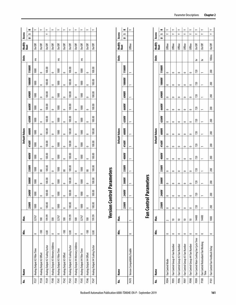
Parameter Descriptions Chapter 2
Vers
ion
Cont
rol P
aram
eter
s
Fan
Cont
rol P
aram
eter
s
P337
Analo
g Out
put #
2 Filt
er Ti
me
032
767
1000
1000
1000
1000
1000
1000
1000
1000
1000
1000
1000
1000
ms
On/O
ffY
P338
Analo
g Out
put #
2 Offs
et-1
0010
00
00
000
00
00
00
0On
/Off
Y
P339
Analo
g Out
put #
2 Sca
ling F
acto
r0.0
019
9.99
100.0
010
0.00
100.0
010
0.00
100.0
010
0.00
100.0
010
0.00
100.0
010
0.00
100.0
010
0.00
On/O
ffY
Y
P340
Analo
g Out
put #
3 Mem
ory A
ddre
ss0
500
00
00
00
00
00
00
On/O
ffY
P341
Analo
g Out
put #
3 Filt
er Ti
me
032
767
1000
1000
1000
1000
1000
1000
1000
1000
1000
1000
1000
1000
ms
On/O
ffY
P342
Analo
g Out
put #
3 Offs
et-1
0010
00
00
000
00
00
00
0On
/Off
Y
P343
Analo
g Out
put #
3 Sca
ling F
acto
r0.0
019
9.99
100.0
010
0.00
100.0
010
0.00
100.0
010
0.00
100.0
010
0.00
100.0
010
0.00
100.0
010
0.00
On/O
ffY
P344
Analo
g Out
put #
4 Mem
ory A
ddre
ss0
500
00
00
00
00
00
00
On/O
ffY
P345
Analo
g Out
put #
4 Filt
er Ti
me
032
767
1000
1000
1000
1000
1000
1000
1000
1000
1000
1000
1000
1000
ms
On/O
ffY
P346
Analo
g Out
put #
4 Offs
et-1
0010
00
00
000
00
00
00
0On
/Off
Y
P347
Analo
g Out
put #
4 Sca
ling F
acto
r0.0
019
9.99
100.0
010
0.00
100.0
010
0.00
100.0
010
0.00
100.0
010
0.00
100.0
010
0.00
100.0
010
0.00
On/O
ffY
No.
Nam
eM
in.
Max
.De
faul
t Val
ues
Units
Mod
ify
Root
Acce
ss
2300
V24
00V
3000
V33
00V
4000
V41
60V
6000
V63
00V
6600
V69
00V
1000
0V11
000V
US
R
No.
Nam
eM
in.
Max
.De
faul
t Val
ues
Units
Mod
ify
Root
Acce
ss
2300
V24
00V
3000
V33
00V
4000
V41
60V
6000
V63
00V
6600
V69
00V
1000
0V11
000V
US
R
P470
Versi
on Co
mpa
tibilit
y Ena
ble0
11
11
11
11
11
11
1Of
fline
Y
No.
Nam
eM
in.
Max
.De
faul
t Val
ues
Units
Mod
ify
Root
Acce
ss
2300
V24
00V
3000
V33
00V
4000
V41
60V
6000
V63
00V
6600
V69
00V
1000
0V11
000V
US
R
P094
Fan C
ontro
l Mod
e0
20
00
00
00
00
00
0Of
fline
YY
P095
Fan C
ontro
l Gro
up #1
Fan N
umbe
r0
100
00
00
00
00
00
0Of
fline
YY
P096
Fan C
ontro
l Gro
up #2
Fan N
umbe
r0
100
00
00
00
00
00
0Of
fline
YY
P097
Fan C
ontro
l Gro
up #3
Fan N
umbe
r0
100
00
00
00
00
00
0Of
fline
YY
P098
Fan C
ontro
l Gro
up #4
Fan N
umbe
r0
100
00
00
00
00
00
0Of
fline
YY
P099
Fan C
ontro
l Main
Cooli
ng Fa
n Cyc
le Tim
e0
1440
072
072
072
072
072
072
072
072
072
072
072
072
0hr
On/O
ffY
Y
P100
Fan C
ontro
l Red
unda
nt Fa
n Wor
king
Time
014
400
11
11
11
11
11
11
hrOn
/Off
YY
P101
Fan C
ontro
l Fan
Feed
back
Dela
y0
1000
200
200
200
200
200
200
200
200
200
200
200
200
100m
sOn
/Off
YY
Rockwell Automation Publication 6000-TD004E-EN-P - September 2019 161
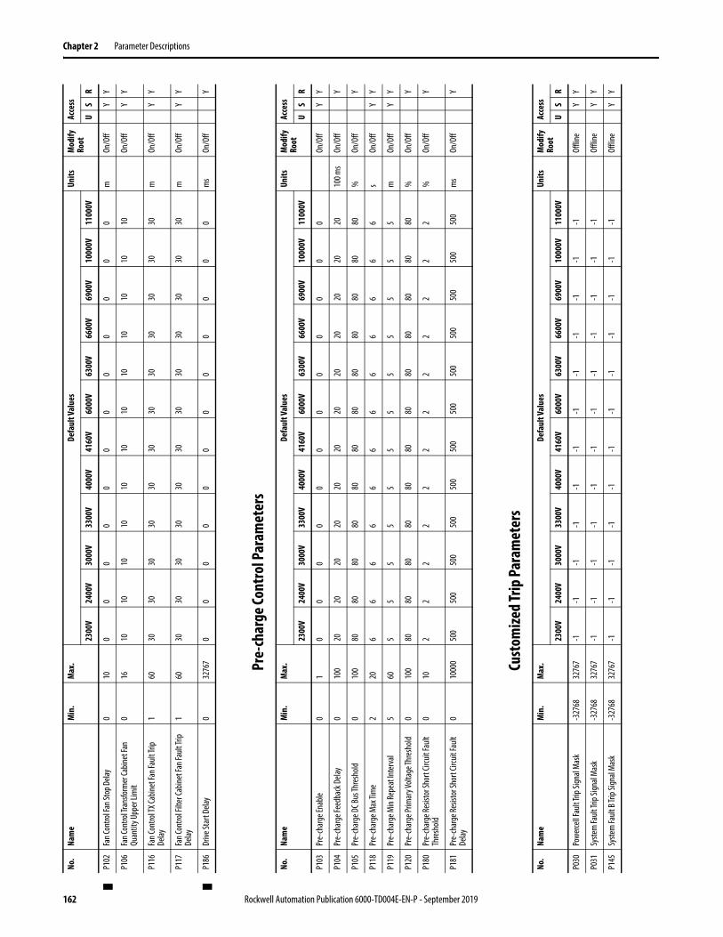
Chapter 2 Parameter Descriptions
Pre-
char
ge Co
ntro
l Par
amet
ers
Cust
omize
d Trip
Par
amet
ers
P102
Fan C
ontro
l Fan
Stop
Dela
y0
100
00
00
00
00
00
0m
On/O
ffY
Y
P106
Fan C
ontro
l Tra
nsfo
rmer
Cabin
et Fa
n Qu
antit
y Upp
er Li
mit
016
1010
1010
1010
1010
1010
1010
On/O
ffY
Y
P116
Fan C
ontro
l TX C
abine
t Fan
Fault
Trip
Delay
160
3030
3030
3030
3030
3030
3030
mOn
/Off
YY
P117
Fan C
ontro
l Filt
er Ca
binet
Fan F
ault T
rip
Delay
160
3030
3030
3030
3030
3030
3030
mOn
/Off
YY
P186
Drive
Star
t Dela
y0
3276
70
00
00
00
00
00
0m
sOn
/Off
Y
No.
Nam
eM
in.
Max
.De
faul
t Val
ues
Units
Mod
ify
Root
Acce
ss
2300
V24
00V
3000
V33
00V
4000
V41
60V
6000
V63
00V
6600
V69
00V
1000
0V11
000V
US
R
No.
Nam
eM
in.
Max
.De
faul
t Val
ues
Units
Mod
ify
Root
Acce
ss
2300
V24
00V
3000
V33
00V
4000
V41
60V
6000
V63
00V
6600
V69
00V
1000
0V11
000V
US
R
P103
Pre-
char
ge En
able
01
00
00
00
00
00
00
On/O
ffY
Y
P104
Pre-
char
ge Fe
edba
ck D
elay
010
020
2020
2020
2020
2020
2020
2010
0 ms
On/O
ffY
P105
Pre-
char
ge D
C Bus
Thre
shold
010
080
8080
8080
8080
8080
8080
80%
On/O
ffY
P118
Pre-
char
ge M
ax Ti
me
220
66
66
66
66
66
66
sOn
/Off
YY
P119
Pre-
char
ge M
in Re
peat
Inte
rval
560
55
55
55
55
55
55
mOn
/Off
YY
P120
Pre-
char
ge Pr
imar
y Volt
age T
hres
hold
010
080
8080
8080
8080
8080
8080
80%
On/O
ffY
P180
Pre-
char
ge Re
sisto
r Sho
rt Cir
cuit
Fault
Th
resh
old0
102
22
22
22
22
22
2%
On/O
ffY
P181
Pre-
char
ge Re
sisto
r Sho
rt Cir
cuit
Fault
De
lay0
1000
050
050
050
050
050
050
050
050
050
050
050
050
0m
sOn
/Off
Y
No.
Nam
eM
in.
Max
.De
faul
t Val
ues
Units
Mod
ify
Root
Acce
ss
2300
V24
00V
3000
V33
00V
4000
V41
60V
6000
V63
00V
6600
V69
00V
1000
0V11
000V
US
R
P030
Powe
rcell F
ault T
rip Si
gnal
Mas
k-3
2768
3276
7-1
-1-1
-1-1
-1-1
-1-1
-1-1
-1Of
fline
YY
P031
Syste
m Fa
ult Tr
ip Sig
nal M
ask
-327
6832
767
-1-1
-1-1
-1-1
-1-1
-1-1
-1-1
Offli
neY
Y
P145
Syste
m Fa
ult B
Trip S
ignal
Mas
k-3
2768
3276
7-1
-1-1
-1-1
-1-1
-1-1
-1-1
-1Of
fline
YY
162 Rockwell Automation Publication 6000-TD004E-EN-P - September 2019

Parameter Descriptions Chapter 2
Over
Spee
d Pa
ram
eter
s
Volta
ge Sa
g Pa
ram
eter
s
No.
Nam
eM
in.
Max
.De
faul
t Val
ues
Units
Mod
ify
Root
Acce
ss
2300
V24
00V
3000
V33
00V
4000
V41
60V
6000
V63
00V
6600
V69
00V
1000
0V11
000V
US
R
P460
Rate
d Out
put F
requ
ency
075
5050
5050
5050
5050
5050
5050
Offli
neY
Y
P466
Max
imum
Out
put F
requ
ency
075
5050
5050
5050
5050
5050
5050
Offli
neY
Y
P467
Over
Spee
d Ena
ble
01
00
00
00
00
00
00
Offli
neY
Y
No.
Nam
eM
in.
Max
.De
faul
t Val
ues
Units
Mod
ify
Root
Acce
ss
2300
V24
00V
3000
V33
00V
4000
V41
60V
6000
V63
00V
6600
V69
00V
1000
0V11
000V
US
R
P182
Dera
ting F
uncti
on En
able
01
11
11
11
11
11
11
On/O
ff
P183
Volta
ge Lo
wer T
hres
hold
For D
rive
Dera
ting P
er Co
oling
Fan I
nput
Volta
ge
Drop
010
070
7070
7070
7070
7070
7070
70On
/Off
P184
Volta
ge U
pper
Thre
shold
For D
rive
Dera
ting P
er Co
oling
Fan I
nput
Volta
ge
Drop
010
075
7575
7575
7575
7575
7575
75On
/Off
P185
Drive
Out
put C
urre
nt U
pper
Lim
itatio
n Pe
r Coo
ling F
an In
put V
oltag
e Dro
p0
100
7676
7676
7676
7676
7676
7676
On/O
ff
P268
Flux C
ontro
l Sign
al Fil
ter T
ime
0.00
1366
3.80
1000
0.08
1000
0.08
1000
0.08
1000
0.08
1000
0.08
1000
0.08
1000
0.08
1000
0.08
1000
0.08
1000
0.08
1000
0.08
1000
0.08
ms
On/O
ffY
P269
Syste
m D
erat
ing Co
ntro
l Sign
al Fil
ter
Time
9.60
1366
3.80
1000
0.08
1000
0.08
1000
0.08
1000
0.08
1000
0.08
1000
0.08
1000
0.08
1000
0.08
1000
0.08
1000
0.08
1000
0.08
1000
0.08
ms
On/O
ffY
P272
Flux C
ontro
l Com
pens
ation
Gain
010
025
2525
2525
2525
2525
2525
25%
On/O
ffY
P273
Flux C
ontro
l Reg
ulatio
n Con
trol E
nabl
e0
11
11
11
11
11
11
1On
/Off
Y
P276
Flux C
ontro
l-Lag
Band
Widt
h0
100
33
33
33
33
33
13
On/O
ffY
P278
Dera
ting C
ontro
l Ena
ble T
hres
hold
50.00
199.9
911
0.00
110.0
011
0.00
110.0
011
0.00
110.0
011
0.00
110.0
011
0.00
110.0
011
0.00
110.0
0On
/Off
YY
P279
Dera
ting C
ontro
l Out
put F
ilter
Tim
e9.9
519
99.94
9.95
9.95
9.95
9.95
9.95
9.95
9.95
9.95
9.95
9.95
9.95
9.95
On/O
ffY
Rockwell Automation Publication 6000-TD004E-EN-P - September 2019 163

Chapter 2 Parameter Descriptions
Volta
ge Lo
op Pa
ram
eter
s
Low
Volta
ge R
ide T
hrou
gh Pa
ram
eter
s
No.
Nam
eM
in.
Max
.De
faul
t Val
ues
Units
Mod
ify
Root
Acce
ss
2300
V24
00V
3000
V33
00V
4000
V41
60V
6000
V63
00V
6600
V69
00V
1000
0V11
000V
US
R
P290
Volta
ge Lo
op En
able
01
11
11
11
11
11
11
Offli
neY
P296
Curre
nt Fe
edba
ck Fi
lter T
ime
010
0010
1010
1010
1010
1010
1010
10m
sOn
/Off
Y
P297
Volta
ge Fe
edba
ck Fi
lter T
ime
010
0010
1010
1010
1010
1010
1010
10m
sOn
/Off
Y
P298
Filte
r Tim
e A Fo
r DC B
us Av
erag
e Valu
e0
1000
100
100
100
100
100
100
100
100
100
100
100
100
ms
On/O
ffY
P299
Filte
r Tim
e B Fo
r DC B
us Av
erag
e Valu
e0
1000
55
55
55
55
55
55
ms
On/O
ffY
No.
Nam
eM
in.
Max
.De
faul
t Val
ues
Units
Mod
ify
Root
Acce
ss
2300
V24
00V
3000
V33
00V
4000
V41
60V
6000
V63
00V
6600
V69
00V
1000
0V11
000V
US
R
P280
Low
Volta
ge Ri
de Th
roug
h Rec
over
y Vo
ltage
Boos
t Coe
fficie
nt0
100
00
00
00
00
00
00
%On
/Off
Y
P281
Low
Volta
ge Ri
de Th
roug
h Min
Tim
e In
terv
al0
1000
1010
1010
1010
1010
1010
1010
sOn
/Off
YY
P282
Low
Volta
ge Ri
de Th
roug
h Min
Fre
quen
cy Li
mit
510
05
55
55
55
55
55
5Of
fline
YY
P283
Low
Volta
ge Ri
de Th
roug
h Ena
ble
01
11
11
11
11
11
11
On/O
ffY
Y
P284
Low
Volta
ge Ri
de Th
roug
h Min
Tim
e Lim
it10
1638
340
4040
4040
4040
4040
4040
40m
sOf
fline
Y
P285
Low
Volta
ge Ri
de Th
roug
h Max
Tim
e Lim
it10
1638
310
0010
0010
0010
0010
0010
0010
0010
0010
0010
0010
0010
00m
sOf
fline
Y
P286
Low
Volta
ge Ri
de Th
roug
h Rec
over
y Fre
quen
cy Co
mpe
nsat
ion Fa
ctor
-200
.0019
9.99
0.00
0.00
0.00
0.00
0.00
0.00
0.00
0.00
0.00
0.00
0.00
0.00
Offli
neY
P287
Low
Volta
ge Ri
de Th
roug
h Rec
over
y Tim
e10
1638
315
0015
0015
0015
0015
0015
0015
0015
0015
0015
0015
0015
00m
sOf
fline
Y
P288
Low
Volta
ge Ri
de Th
roug
h Sys
tem
Dela
y Co
rrecti
on Fa
ctor
-100
00.00
1000
0.00
999.7
699
9.76
999.7
699
9.76
999.7
699
9.76
999.7
699
9.76
999.7
699
9.76
999.7
699
9.76
μsOf
fline
Y
P289
Low
Volta
ge Ri
de Th
roug
h Mot
or Sp
eed
Estim
ation
Filte
r Tim
e0.9
810
00.00
9.95
9.95
9.95
9.95
9.95
9.95
9.95
9.95
9.95
9.95
9.95
9.95
ms
Offli
neY
164 Rockwell Automation Publication 6000-TD004E-EN-P - September 2019

Parameter Descriptions Chapter 2
Powe
r Los
s Aut
o Res
tart
Para
met
ers
Cell
Bypa
ss Pa
ram
eter
s
No.
Nam
eM
in.
Max
.De
faul
t Val
ues
Units
Mod
ify
Root
Acce
ss
2300
V24
00V
3000
V33
00V
4000
V41
60V
6000
V63
00V
6600
V69
00V
1000
0V11
000V
US
R
P073
Inpu
t Volt
age L
oss F
ilter
Tim
e0
1000
00
00
00
00
00
00
ms
On/O
ffY
P263
Powe
r Los
s Res
tart
Enab
le0
10
00
00
00
00
00
0Of
fline
YY
P264
Powe
r Los
s Allo
wabl
e Tim
e0
3600
6060
6060
6060
6060
6060
6060
sOf
fline
YY
P265
Powe
r Los
s Tim
e Max
Lim
it0
3600
300
300
300
300
300
300
300
300
300
300
300
300
sOf
fline
Y
No.
Nam
eM
in.
Max
.De
faul
t Val
ues
Units
Mod
ify
Root
Acce
ss
2300
V24
00V
3000
V33
00V
4000
V41
60V
6000
V63
00V
6600
V69
00V
1000
0V11
000V
US
R
P041
Powe
r Cell
Bypa
ss En
able
01
00
00
00
00
00
00
Offli
neY
Y
P042
Powe
r Cell
Bypa
ss De
lay Af
ter P
ower
Cell
Bypa
ssed
2016
000
500
500
500
500
500
500
500
500
500
500
500
500
ms
On/O
ffY
P043
Powe
r Cell
Bypa
ss Up
per L
imit
For
Bypa
ssed F
eedb
ack T
ime
3050
010
010
010
010
010
010
010
010
010
010
010
010
0m
sOn
/Off
Y
P044
Powe
r Cell
Bypa
ss Fa
ult Si
mula
tion
Powe
r Cell
Coun
t0
30
00
00
00
00
00
0On
/Off
YY
P057
Powe
r Cell
Bypa
ss Up
per L
imit T
ime F
or
Over
Tem
pera
ture
032
767
1010
1010
1010
1010
1010
1010
sOn
/Off
Y
P058
Powe
r Cell
Bypa
ss Ph
ase A
Cell N
umbe
r Fo
r Sim
ulat
ion0
90
00
00
00
00
00
0On
/Off
YY
P059
Powe
r Cell
Bypa
ss Ph
ase B
Cell N
umbe
r Fo
r Sim
ulat
ion0
180
00
00
00
00
00
0On
/Off
YY
P060
Powe
r Cell
Bypa
ss Ph
ase C
Cell N
umbe
r Fo
r Sim
ulat
ion0
270
00
00
00
00
00
0On
/Off
YY
P061
Powe
r Cell
Bypa
ss Fa
ult Si
mula
tion
-327
6832
767
00
00
00
00
00
00
On/O
ffY
Y
P065
Powe
r Cell
Bypa
ss En
able
Frequ
ency
Ra
nge L
ower
limit
0.00
19.99
0.00
0.00
0.00
0.00
0.00
0.00
0.00
0.00
0.00
0.00
0.00
0.00
On/O
ffY
P066
Powe
r Cell
Bypa
ss Re
start
Enab
le Af
ter
Powe
r Cell
Bypa
ssed
01
11
11
11
11
11
11
Offli
neY
P068
One P
hase
Lost
Filte
r Tim
e 5
1000
3030
3030
3030
3030
3030
3030
10 m
sOn
/Off
YY
P078
Powe
r Cell
Reac
tivat
ion Ti
me U
pper
Lim
it 0
200
100
100
100
100
100
100
100
100
100
100
100
100
ms
On/O
ffY
Rockwell Automation Publication 6000-TD004E-EN-P - September 2019 165

Chapter 2 Parameter Descriptions
Bypa
ss M
ode S
witc
h Pa
ram
eter
s
Faul
t Aut
omat
ic Sw
itch
to B
ypas
s Par
amet
ers
Curre
nt Li
mit
Para
met
ers
No.
Nam
eM
in.
Max
.De
faul
t Val
ues
Units
Mod
ify
Root
Acce
ss
2300
V24
00V
3000
V33
00V
4000
V41
60V
6000
V63
00V
6600
V69
00V
1000
0V11
000V
US
R
P484
Bypa
ss M
ode S
electi
on0
40
00
00
00
00
00
0Of
fline
YY
No.
Nam
eM
in.
Max
.De
faul
t Val
ues
Units
Mod
ify
Root
Acce
ss
2300
V24
00V
3000
V33
00V
4000
V41
60V
6000
V63
00V
6600
V69
00V
1000
0V11
000V
US
R
P471
Fault
-To-B
ypas
s0
10
00
00
00
00
00
0Of
fline
YY
P472
Fault
-To-B
ypas
s Dela
y0
53
33
33
33
33
33
3On
/Off
YY
P473
Fault
-To-B
ypas
s Dela
y Whe
n Sta
rting
Th
e Mot
or0
6060
6060
6060
6060
6060
6060
60s
On/O
ffY
Y
P474
Fault
-To-B
ypas
s Mini
mum
Freq
uenc
y0
755
55
55
55
55
55
5Hz
Offli
neY
Y
No.
Nam
eM
in.
Max
.De
faul
t Val
ues
Units
Mod
ify
Root
Acce
ss
2300
V24
00V
3000
V33
00V
4000
V41
60V
6000
V63
00V
6600
V69
00V
1000
0V11
000V
US
R
P133
Curre
nt Li
mit
Loop
Kp0.0
128.0
0.30.3
0.30.3
0.30.3
0.30.3
0.30.3
0.30.3
On/O
ffY
P134
Curre
nt Li
mit
Loop
Ki0.0
128.0
1.01.0
1.01.0
1.01.0
1.01.0
1.01.0
1.01.0
On/O
ffY
P135
Curre
nt Li
mit
Loop
Kd0
1280
00
00
00
00
00
00
0*0
.001
On/O
ffY
P436
Curre
nt Li
mita
tion E
nable
01
11
11
11
11
11
11
On/O
ffY
Y
P438
Curre
nt Li
mita
tion E
nable
Freq
uenc
y Ra
nge L
ower
Lim
it0
100
00
00
00
00
00
00
On/O
ffY
Y
P441
Curre
nt Li
mita
tion T
hres
hold
0.00
399.9
910
0.00
100.0
010
0.00
100.0
010
0.00
100.0
010
0.00
100.0
010
0.00
100.0
010
0.00
100.0
0On
/Off
YY
P442
Curre
nt Li
mita
tion H
eatin
g Tim
e0
1638
460
6060
6060
6060
6060
6060
60s
On/O
ffY
Y
P443
Curre
nt Li
mita
tion C
oolin
g Tim
e0
1638
454
054
054
054
054
054
054
054
054
054
054
054
0s
On/O
ffY
Y
P444
Curre
nt Li
mita
tion D
ecel
Ram
p Slop
e Ch
ange
0.00
399.9
9Fra
me A
11
0.00
Fram
e B
120.0
0
Fram
e A
110.0
0Fra
me B
12
0.00
Fram
e A
110.0
0Fra
me B
12
0.00
Fram
e A
110.0
0Fra
me B
12
0.00
Fram
e A
110.0
0Fra
me B
12
0.00
Fram
e A
110.0
0Fra
me B
12
0.00
Fram
e A
110.0
0Fra
me B
12
0.00
Fram
e A
110.0
0Fra
me B
12
0.00
Fram
e A
110.0
0Fra
me B
12
0.00
Fram
e A
110.0
0Fra
me B
12
0.00
Fram
e A
110.0
0Fra
me B
12
0.00
Fram
e A
110.0
0Fra
me B
12
0.00
On/O
ffY
Y
P445
Curre
nt Li
mita
tion C
ycle
Load
Cont
rol
Enab
le0
10
00
00
00
00
00
0On
/Off
YY
166 Rockwell Automation Publication 6000-TD004E-EN-P - September 2019
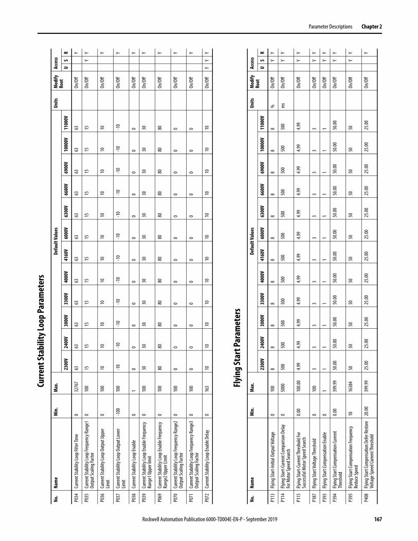
Parameter Descriptions Chapter 2
Curre
nt St
abili
ty Lo
op Pa
ram
eter
s
Flyi
ng St
art P
aram
eter
s
No.
Nam
eM
in.
Max
.De
faul
t Val
ues
Units
Mod
ify
Root
Acce
ss
2300
V24
00V
3000
V33
00V
4000
V41
60V
6000
V63
00V
6600
V69
00V
1000
0V11
000V
US
R
P034
Curre
nt St
abilit
y Loo
p Filt
er Ti
me
032
767
6363
6363
6363
6363
6363
6363
On/O
ffY
P035
Curre
nt St
abilit
y Loo
p Fre
quen
cy Ra
nge1
Ou
tput
Scali
ng Fa
ctor
010
015
1515
1515
1515
1515
1515
15On
/Off
YY
P036
Curre
nt St
abilit
y Loo
p Out
put U
pper
Lim
it0
100
1010
1010
1010
1010
1010
1010
On/O
ffY
P037
Curre
nt St
abilit
y Loo
p Out
put L
ower
Lim
it-1
0010
0-1
0-1
0-1
0-1
0-1
0-1
0-1
0-1
0-1
0-1
0-1
0-1
0On
/Off
Y
P038
Curre
nt St
abilit
y Loo
p Ena
ble
01
00
00
00
00
00
00
On/O
ffY
P039
Curre
nt St
abilit
y Loo
p Ena
ble F
requ
ency
Ra
nge1
Upp
er lim
it0
100
3030
3030
3030
3030
3030
3030
On/O
ffY
P069
Curre
nt St
abilit
y Loo
p Ena
ble F
requ
ency
Ra
nge2
Upp
er Li
mit
010
080
8080
8080
8080
8080
8080
80On
/Off
Y
P070
Curre
nt St
abilit
y Loo
p Fre
quen
cy Ra
nge2
Ou
tput
Scali
ng Fa
ctor
010
00
00
00
00
00
00
0On
/Off
Y
P071
Curre
nt St
abilit
y Loo
p Fre
quen
cy Ra
nge3
Ou
tput
Scali
ng Fa
ctor
010
00
00
00
00
00
00
0On
/Off
Y
P072
Curre
nt St
abilit
y Loo
p Ena
ble D
elay
016
310
1010
1010
1010
1010
1010
10On
/Off
YY
Y
No.
Nam
eM
in.
Max
.De
faul
t Val
ues
Units
Mod
ify
Root
Acce
ss
2300
V24
00V
3000
V33
00V
4000
V41
60V
6000
V63
00V
6600
V69
00V
1000
0V11
000V
US
R
P113
Flyin
g Sta
rt-In
itial
Outp
ut Vo
ltage
010
08
88
88
88
88
88
8%
On/O
ffY
Y
P114
Flying
Star
t-Cur
rent
Com
paris
on D
elay
For M
otor
Spee
d Sea
rch0
5000
500
500
500
500
500
500
500
500
500
500
500
500
ms
On/O
ffY
Y
P115
Flying
Star
t-Cur
rent
Thre
shold
For
Succ
essfu
l Mot
or Sp
eed S
earch
0.00
100.0
04.9
94.9
94.9
94.9
94.9
94.9
94.9
94.9
94.9
94.9
94.9
94.9
9On
/Off
YY
P187
Flyin
g Sta
rt Vo
ltage
Thre
shold
010
03
33
33
33
33
33
3On
/Off
YY
P393
Flyin
g Sta
rt Co
mpe
nsat
ion En
able
01
11
11
11
11
11
11
On/O
ffY
Y
P394
Flying
Star
t Com
pens
ation
Curre
nt
Thre
shold
0.00
399.9
950
.0050
.0050
.0050
.0050
.0050
.0050
.0050
.0050
.0050
.0050
.0050
.00On
/Off
YY
P395
Flying
Star
t Com
pens
ation
Freq
uenc
y Re
duce
Spee
d10
1638
450
5050
5050
5050
5050
5050
50On
/Off
YY
P408
Flying
Star
t Com
pens
ation
Def
er Re
store
Vo
ltage
Spee
d Cur
rent
Thre
shold
20.00
399.9
925
.0025
.0025
.0025
.0025
.0025
.0025
.0025
.0025
.0025
.0025
.0025
.00On
/Off
Y
Rockwell Automation Publication 6000-TD004E-EN-P - September 2019 167

Chapter 2 Parameter Descriptions
Load
Loss
Cont
rol P
aram
eter
s
Mot
or A
uto-
tune
Para
met
ers
P410
Flying
Star
t Com
pens
ation
Curre
nt
Thre
shold
for F
ast C
ompe
nsat
ion
0.00
399.9
960
.0060
.0060
.0060
.0060
.0060
.0060
.0060
.0060
.0060
.0060
.0060
.00On
/Off
Y
P416
Flyin
g Sta
rt M
ode
03
00
00
00
00
00
00
On/O
ffY
Y
P417
Flyin
g Sta
rt M
otor
Spee
d Sea
rch Ti
meo
ut0
1000
5050
5050
5050
5050
5050
5050
sOn
/Off
YY
P457
Flying
Star
t Volt
age R
ecov
ery T
ime (
Low
Spee
d Reg
ion)
0.00
163.8
410
.0010
.0010
.0010
.0010
.0010
.0010
.0010
.0010
.0010
.0010
.0010
.00s
On/O
ffY
Y
P459
Flyin
g Sta
rt Vo
ltage
Reco
very
Tim
e (Hi
gh
Spee
d Reg
ion)
0.00
163.8
410
.0010
.0010
.0010
.0010
.0010
.0010
.0010
.0010
.0010
.0010
.0010
.00s
On/O
ffY
Y
P463
Flying
Star
t Low
/High
Spee
d Reg
ions
Boun
dary
010
016
1616
1616
1616
1616
1616
16%
On/O
ffY
Y
No.
Nam
eM
in.
Max
.De
faul
t Val
ues
Units
Mod
ify
Root
Acce
ss
2300
V24
00V
3000
V33
00V
4000
V41
60V
6000
V63
00V
6600
V69
00V
1000
0V11
000V
US
R
No.
Nam
eM
in.
Max
.De
faul
t Val
ues
Units
Mod
ify
Root
Acce
ss
2300
V24
00V
3000
V33
00V
4000
V41
60V
6000
V63
00V
6600
V69
00V
1000
0V11
000V
US
R
P045
Load
Loss
Cont
rol E
nabl
e0
10
00
00
00
00
00
0On
/Off
YY
P046
Load
Loss
Enab
le Fre
quen
cy0
100
2020
2020
2020
2020
2020
2020
%On
/Off
YY
P047
Load
Loss
Cont
rol D
iffer
entia
l Sca
ling
020
008
88
88
88
88
88
8%
On/O
ffY
P048
Load
Loss
Frequ
ency
Com
pens
ation
Up
per L
imit
05
55
55
55
55
55
55
%On
/Off
YY
P049
Load
Loss
Cont
rol S
calin
g Fac
tor
020
000
00
00
00
00
00
0%
On/O
ffY
P050
Load
Loss
Cont
rol In
tegr
al Tim
e0
100
00
00
00
00
00
00
ms
On/O
ffY
P051
Load
Loss
Cont
rol F
ilter
Tim
e0
200
100
100
100
100
100
100
100
100
100
100
100
100
ms
On/O
ffY
P052
Load
Loss
Enab
le Cu
rrent
Thre
shold
010
010
1010
1010
1010
1010
1010
10%
On/O
ffY
P053
Load
Loss
Cont
rol E
xit D
elay
016
000
5000
5000
5000
5000
5000
5000
5000
5000
5000
5000
5000
5000
ms
On/O
ffY
No.
Nam
eM
in.
Max
.De
faul
t Val
ues
Units
Mod
ify
Root
Acce
ss
2300
V24
00V
3000
V33
00V
4000
V41
60V
6000
V63
00V
6600
V69
00V
1000
0V11
000V
US
R
P121
Mot
or Au
totu
ne Se
lectio
n0
30
00
00
00
00
00
0Of
fline
YY
P122
Mot
or Au
totu
ne D
elay
032
767
2000
2000
2000
2000
2000
2000
2000
2000
2000
2000
2000
2000
ms
On/O
ffY
P123
Mot
or Au
totu
ne Fi
lter T
ime
032
767
1010
1010
1010
1010
1010
1010
ms
On/O
ffY
168 Rockwell Automation Publication 6000-TD004E-EN-P - September 2019

Parameter Descriptions Chapter 2
Rest
art P
aram
eter
s
P124
Mot
or Au
totu
ne Cu
rrent
Id Kp
0.00
128.0
00.0
10.0
10.0
10.0
10.0
10.0
10.0
10.0
10.0
10.0
10.0
10.0
1On
/Off
Y
P125
Mot
or Au
totu
ne Cu
rrent
Id Ki
0.012
8.00.1
0.10.1
0.10.1
0.10.1
0.10.1
0.10.1
0.1On
/Off
Y
P126
Mot
or Au
totu
ne Cu
rrent
Iq Kp
0.00
128.0
00.0
10.0
10.0
10.0
10.0
10.0
10.0
10.0
10.0
10.0
10.0
10.0
1On
/Off
Y
P127
Mot
or Au
totu
ne Cu
rrent
Iq Ki
0.012
8.00.1
0.10.1
0.10.1
0.10.1
0.10.1
0.10.1
0.1On
/Off
Y
P128
Mot
or Au
totu
ne Id
Feed
back
Erro
r Vali
d0.0
010
0.00
0.99
0.99
0.99
0.99
0.99
0.99
0.99
0.99
0.99
0.99
0.99
0.99
%On
/Off
Y
P129
Mot
or Au
totu
ne Lr
/Lm
032
767
1052
610
526
1052
610
526
1052
610
526
1052
610
526
1052
610
526
1052
610
526
*0.00
01On
/Off
YY
P130
Mot
or Au
totu
ne Id
Refe
renc
e0.0
010
0.00
29.99
29.99
29.99
29.99
29.99
29.99
29.99
29.99
29.99
29.99
29.99
29.99
On/O
ffY
P131
Mot
or Au
totu
ne Iq
Refe
renc
e0
100
00
00
00
00
00
00
On/O
ffY
P132
Mot
or Au
totu
ne Ti
me L
imit
032
767
5000
5000
5000
5000
5000
5000
5000
5000
5000
5000
5000
5000
mOn
/Off
Y
P136
Mot
or Au
totu
ne Rs
/Rr
0.00
327.6
71.3
01.3
01.3
01.3
01.3
01.3
01.3
01.3
01.3
01.3
01.3
01.3
0On
/Off
Y
P137
Mot
or Ra
ted C
urre
nt0
3276
70
00
00
00
00
00
0A
On/O
ffY
Y
P138
Mot
or St
ator
Resis
tanc
e Rs
010
00
00
00
00
00
00
ΩOn
/Off
YY
P139
Mot
or M
agne
tizing
Curre
nt Id
010
030
3030
3030
3030
3030
3030
30%
On/O
ffy
Y
P140
Mot
or Ro
tor R
esist
ance
Rr0
100
00
00
00
00
00
0Ω
On/O
ffY
Y
P141
Mot
or M
agne
tizing
Indu
ctanc
e Lm
0.032
76.7
0.00.0
0.00.0
0.00.0
0.00.0
0.00.0
0.00.0
mH
On/O
ffY
Y
P142
Mot
or St
ator
Leak
age I
nduc
tanc
e LIs
0.032
76.7
0.00.0
0.00.0
0.00.0
0.00.0
0.00.0
0.00.0
mH
On/O
ffY
Y
P143
Mot
or Ro
tor L
eaka
ge In
ducta
nce L
lr0.0
3276
.70.0
0.00.0
0.00.0
0.00.0
0.00.0
0.00.0
0.0m
HOn
/Off
YY
P178
Mot
or Au
totu
ne Rs
Upp
er Li
mit
010
050
5050
5050
5050
5050
5050
50%
On/O
ffY
P179
Mot
or Au
totu
ne M
axim
um Iq
For N
o Lo
ad0.0
039
9.99
30.00
30.00
30.00
30.00
30.00
30.00
30.00
30.00
30.00
30.00
30.00
30.00
%On
/Off
Y
No.
Nam
eM
in.
Max
.De
faul
t Val
ues
Units
Mod
ify
Root
Acce
ss
2300
V24
00V
3000
V33
00V
4000
V41
60V
6000
V63
00V
6600
V69
00V
1000
0V11
000V
US
R
No.
Nam
eM
in.
Max
.De
faul
t Val
ues
Units
Mod
ify
Root
Acce
ss
2300
V24
00V
3000
V33
00V
4000
V41
60V
6000
V63
00V
6600
V69
00V
1000
0V11
000V
US
R
P461
Resta
rt En
able
01
00
00
00
00
00
00
On/O
ffY
Y
P462
Fault
Rese
t Tim
eout
0.04
120.0
012
0.00
120.0
012
0.00
120.0
012
0.00
120.0
012
0.00
120.0
012
0.00
120.0
012
0.00
120.0
0s
On/O
ffY
P465
Powe
r Cell
Faul
t Aut
o Res
et D
elay
010
44
44
44
44
44
44
sOn
/Off
Y
Rockwell Automation Publication 6000-TD004E-EN-P - September 2019 169
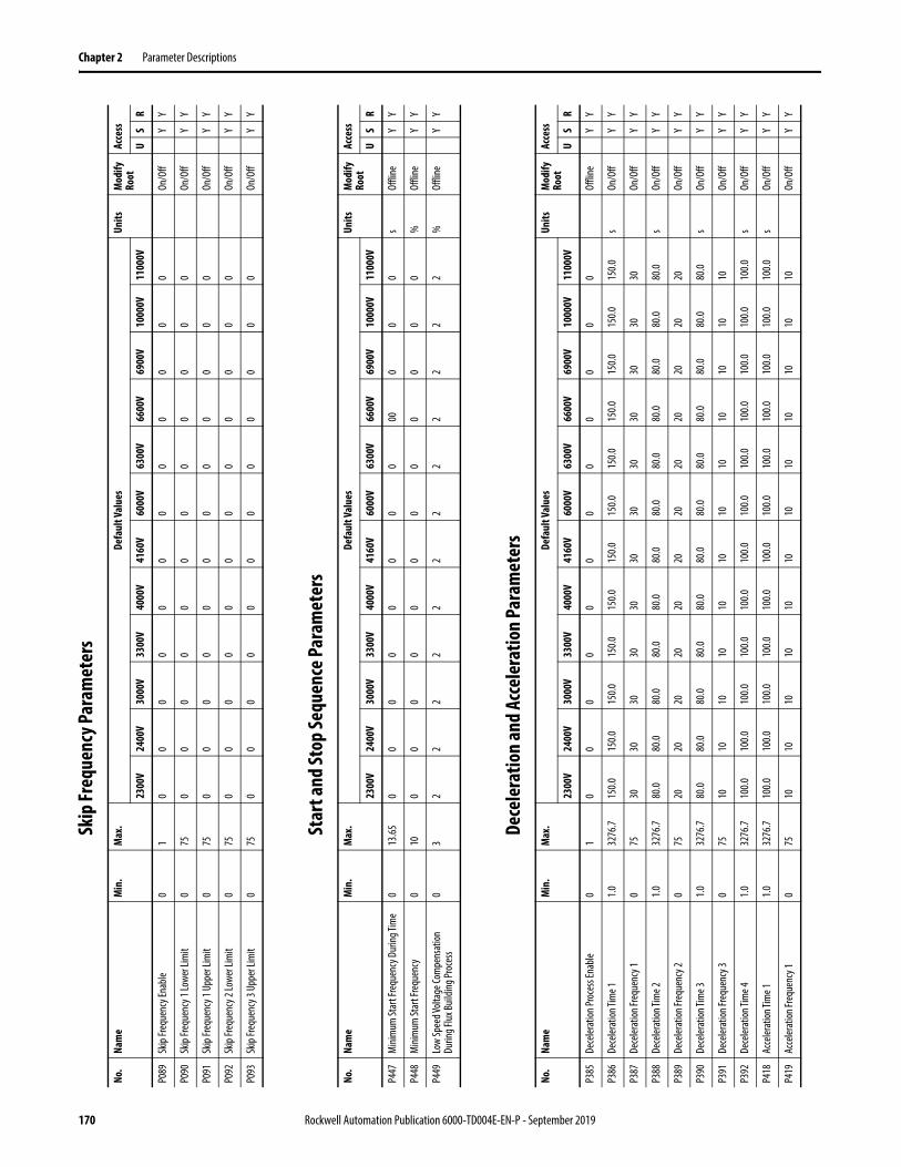
Chapter 2 Parameter Descriptions
Skip
Freq
uenc
y Par
amet
ers
Star
t and
Stop
Sequ
ence
Para
met
ers
Dece
lera
tion
and
Acce
lera
tion
Para
met
ers
No.
Nam
eM
in.
Max
.De
faul
t Val
ues
Units
Mod
ify
Root
Acce
ss
2300
V24
00V
3000
V33
00V
4000
V41
60V
6000
V63
00V
6600
V69
00V
1000
0V11
000V
US
R
P089
Skip
Frequ
ency
Enab
le0
10
00
00
00
00
00
0On
/Off
YY
P090
Skip
Frequ
ency
1 Lo
wer L
imit
075
00
00
00
00
00
00
On/O
ffY
Y
P091
Skip
Frequ
ency
1 Up
per L
imit
075
00
00
00
00
00
00
On/O
ffY
Y
P092
Skip
Frequ
ency
2 Lo
wer L
imit
075
00
00
00
00
00
00
On/O
ffY
Y
P093
Skip
Frequ
ency
3 Up
per L
imit
075
00
00
00
00
00
00
On/O
ffY
Y
No.
Nam
eM
in.
Max
.De
faul
t Val
ues
Units
Mod
ify
Root
Acce
ss
2300
V24
00V
3000
V33
00V
4000
V41
60V
6000
V63
00V
6600
V69
00V
1000
0V11
000V
US
R
P447
Min
imum
Star
t Fre
quen
cy D
uring
Tim
e0
13.65
00
00
00
00
000
00
sOf
fline
YY
P448
Min
imum
Star
t Fre
quen
cy0
100
00
00
00
00
00
0%
Offli
neY
Y
P449
Low
Spee
d Volt
age C
ompe
nsat
ion
Durin
g Flux
Build
ing Pr
oces
s0
32
22
22
22
22
22
2%
Offli
neY
Y
No.
Nam
eM
in.
Max
.De
faul
t Val
ues
Units
Mod
ify
Root
Acce
ss
2300
V24
00V
3000
V33
00V
4000
V41
60V
6000
V63
00V
6600
V69
00V
1000
0V11
000V
US
R
P385
Dece
lerat
ion Pr
oces
s Ena
ble
01
00
00
00
00
00
00
Offli
neY
Y
P386
Dece
lerat
ion Ti
me 1
1.032
76.7
150.0
150.0
150.0
150.0
150.0
150.0
150.0
150.0
150.0
150.0
150.0
150.0
sOn
/Off
YY
P387
Dece
lerat
ion Fr
eque
ncy 1
075
3030
3030
3030
3030
3030
3030
On/O
ffY
Y
P388
Dece
lerat
ion Ti
me 2
1.032
76.7
80.0
80.0
80.0
80.0
80.0
80.0
80.0
80.0
80.0
80.0
80.0
80.0
sOn
/Off
YY
P389
Dece
lerat
ion Fr
eque
ncy 2
075
2020
2020
2020
2020
2020
2020
On/O
ffY
Y
P390
Dece
lerat
ion Ti
me 3
1.032
76.7
80.0
80.0
80.0
80.0
80.0
80.0
80.0
80.0
80.0
80.0
80.0
80.0
sOn
/Off
YY
P391
Dece
lerat
ion Fr
eque
ncy 3
075
1010
1010
1010
1010
1010
1010
On/O
ffY
Y
P392
Dece
lerat
ion Ti
me 4
1.032
76.7
100.0
100.0
100.0
100.0
100.0
100.0
100.0
100.0
100.0
100.0
100.0
100.0
sOn
/Off
YY
P418
Acce
lerat
ion Ti
me 1
1.032
76.7
100.0
100.0
100.0
100.0
100.0
100.0
100.0
100.0
100.0
100.0
100.0
100.0
sOn
/Off
YY
P419
Acce
lerat
ion Fr
eque
ncy 1
075
1010
1010
1010
1010
1010
1010
On/O
ffY
Y
170 Rockwell Automation Publication 6000-TD004E-EN-P - September 2019
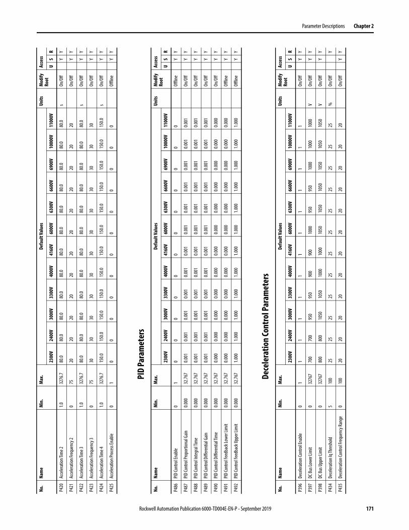
Parameter Descriptions Chapter 2
PID
Para
met
ers
Dece
lera
tion
Cont
rol P
aram
eter
s
P420
Acce
lerat
ion Ti
me 2
1.032
76.7
80.0
80.0
80.0
80.0
80.0
80.0
80.0
80.0
80.0
80.0
80.0
80.0
sOn
/Off
YY
P421
Acce
lerat
ion Fr
eque
ncy 2
075
2020
2020
2020
2020
2020
2020
On/O
ffY
Y
P422
Acce
lerat
ion Ti
me 3
1.032
76.7
80.0
80.0
80.0
80.0
80.0
80.0
80.0
80.0
80.0
80.0
80.0
80.0
sOn
/Off
YY
P423
Acce
lerat
ion Fr
eque
ncy 3
075
3030
3030
3030
3030
3030
3030
On/O
ffY
Y
P424
Acce
lerat
ion Ti
me 4
1.032
76.7
150.0
150.0
150.0
150.0
150.0
150.0
150.0
150.0
150.0
150.0
150.0
150.0
sOn
/Off
YY
P425
Acce
lerat
ion Pr
oces
s Ena
ble
01
00
00
00
00
00
00
Offli
neY
Y
No.
Nam
eM
in.
Max
.De
faul
t Val
ues
Units
Mod
ify
Root
Acce
ss
2300
V24
00V
3000
V33
00V
4000
V41
60V
6000
V63
00V
6600
V69
00V
1000
0V11
000V
US
R
No.
Nam
eM
in.
Max
.De
faul
t Val
ues
Units
Mod
ify
Root
Acce
ss
2300
V24
00V
3000
V33
00V
4000
V41
60V
6000
V63
00V
6600
V69
00V
1000
0V11
000V
US
R
P486
PID
Cont
rol E
nabl
e0
10
00
00
00
00
00
0Of
fline
YY
P487
PID
Cont
rol P
ropo
rtion
al Ga
in0.0
0032
.767
0.001
0.001
0.001
0.001
0.001
0.001
0.001
0.001
0.001
0.001
0.001
0.001
On/O
ffY
Y
P488
PID
Cont
rol In
tegr
al Tim
e0.0
0032
.767
0.001
0.001
0.001
0.001
0.001
0.001
0.001
0.001
0.001
0.001
0.001
0.001
On/O
ffY
Y
P489
PID
Cont
rol D
iffer
entia
l Gain
0.000
32.76
70.0
010.0
010.0
010.0
010.0
010.0
010.0
010.0
010.0
010.0
010.0
010.0
01On
/Off
YY
P490
PID
Cont
rol D
iffer
entia
l Tim
e0.0
0032
.767
0.000
0.000
0.000
0.000
0.000
0.000
0.000
0.000
0.000
0.000
0.000
0.000
On/O
ffY
Y
P491
PID
Cont
rol F
eedb
ack L
ower
Lim
it0.0
0032
.767
0.000
0.000
0.000
0.000
0.000
0.000
0.000
0.000
0.000
0.000
0.000
0.000
Offli
neY
Y
P492
PID
Cont
rol F
eedb
ack U
pper
Lim
it0.0
0032
.767
1.000
1.000
1.000
1.000
1.000
1.000
1.000
1.000
1.000
1.000
1.000
1.000
Offli
neY
Y
No.
Nam
eM
in.
Max
.De
faul
t Val
ues
Units
Mod
ify
Root
Acce
ss
2300
V24
00V
3000
V33
00V
4000
V41
60V
6000
V63
00V
6600
V69
00V
1000
0V11
000V
US
R
P396
Dece
lerat
ion Co
ntro
l Ena
ble0
11
11
11
11
11
11
1On
/Off
YY
P397
DC Bu
s Low
er Li
mit
032
767
700
700
950
950
900
900
1000
950
950
1000
1000
1000
VOn
/Off
YY
P398
DC Bu
s Upp
er Li
mit
032
767
800
800
1050
1050
1000
1000
1050
1050
1050
1050
1050
1050
VOn
/Off
YY
P434
Dece
lerat
ion Iq
Thre
shold
510
025
2525
2525
2525
2525
2525
25%
On/O
ffY
P435
Dece
lerat
ion Co
ntro
l Fre
quen
cy Ra
nge
010
020
2020
2020
2020
2020
2020
20On
/Off
YY
Rockwell Automation Publication 6000-TD004E-EN-P - September 2019 171

Chapter 2 Parameter Descriptions
Prot
ectio
n Pa
ram
eter
sNo
.Na
me
Min
.M
ax.
Defa
ult V
alue
sUn
itsM
odify
Ro
otAc
cess
2300
V24
00V
3000
V33
00V
4000
V41
60V
6000
V63
00V
6600
V69
00V
1000
0V11
000V
US
R
P079
VFD
Mini
mum
Ove
rload
Curre
nt0.0
039
9.99
100.0
010
0.00
100.0
010
0.00
100.0
010
0.00
100.0
010
0.00
100.0
010
0.00
100.0
010
0.00
%On
/Off
YY
P080
VFD
Over
load C
urre
nt0.0
039
9.99
Fram
e A
110.0
0Fra
me B
12
0.00
Fram
e A
110.0
0Fra
me B
12
0.00
Fram
e A
110.0
0Fra
me B
12
0.00
Fram
e A
110.0
0Fra
me B
12
0.00
Fram
e A
110.0
0Fra
me B
12
0.00
Fram
e A
110.0
0Fra
me B
12
0.00
Fram
e A
110.0
0Fra
me B
12
0.00
Fram
e A
110.0
0Fra
me B
12
0.00
Fram
e A
110.0
0Fra
me B
12
0.00
Fram
e A
110.0
0Fra
me B
12
0.00
Fram
e A
110.0
0Fra
me B
12
0.00
Fram
e A
110.0
0Fra
me B
12
0.00
%On
/Off
YY
P081
VFD
Over
load T
ime
032
767
6060
6060
6060
6060
6060
6060
sOn
/Off
YY
P082
VFD
Over
load C
ycle
Time
032
767
600
600
600
600
600
600
600
600
600
600
600
600
sOn
/Off
YY
P107
VFD
Over
load C
urre
nt O
ffset
0.00
399.9
94.9
94.9
94.9
94.9
94.9
94.9
94.9
94.9
94.9
94.9
94.9
94.9
9%
On/O
ffY
P108
Mot
or O
verlo
ad Cu
rrent
Offs
et0.0
039
9.99
4.99
4.99
4.99
4.99
4.99
4.99
4.99
4.99
4.99
4.99
4.99
4.99
%On
/Off
Y
P110
Heat
ing Cu
rrent
Thre
shold
0.00
399.9
9Fra
me A
10
5.00
Fram
e B
110.0
0
Fram
e A
105.0
0Fra
me B
11
0.00
Fram
e A
105.0
0Fra
me B
11
0.00
Fram
e A
105.0
0Fra
me B
11
0.00
Fram
e A
105.0
0Fra
me B
11
0.00
Fram
e A
105.0
0Fra
me B
11
0.00
Fram
e A
105.0
0Fra
me B
11
0.00
Fram
e A
105.0
0Fra
me B
11
0.00
Fram
e A
105.0
0Fra
me B
11
0.00
Fram
e A
105.0
0Fra
me B
11
0.00
Fram
e A
105.0
0Fra
me B
11
0.00
Fram
e A
105.0
0Fra
me B
11
0.00
%On
/Off
Y
P154
Line O
ver V
oltag
e Fau
lt Thr
esho
ld0.0
019
9.99
115.0
011
5.00
115.0
011
5.00
115.0
011
5.00
115.0
011
5.00
115.0
011
5.00
115.0
011
5.00
%On
/Off
YY
P155
Line O
ver V
oltag
e Fau
lt De
lay0
3276
710
1010
1010
1010
1010
1010
10m
sOn
/Off
YY
P156
Line U
nder
Volta
ge W
arnin
g Thr
esho
ld0
100
8080
8080
8080
8080
8080
8080
%On
/Off
YY
P157
Line U
nder
Volta
ge W
arnin
g Dela
y0
3276
710
0010
0010
0010
0010
0010
0010
0010
0010
0010
0010
0010
00m
sOn
/Off
YY
P158
Line N
eutra
l Ove
r Volt
age W
arnin
g Th
resh
old
0.00
199.9
960
.0060
.0060
.0060
.0060
.0060
.0060
.0060
.0060
.0060
.0060
.0060
.00%
On/O
ffY
Y
P159
Line N
eutra
l Ove
r Volt
age W
arnin
g Dela
y0
3276
710
0010
0010
0010
0010
0010
0010
0010
0010
0010
0010
0010
00m
sOn
/Off
YY
P160
Line N
eutra
l Ove
r Volt
age F
ault
Thre
shold
0.00
199.9
980
.0080
.0080
.0080
.0080
.0080
.0080
.0080
.0080
.0080
.0080
.0080
.00%
On/O
ffY
Y
P161
Line N
eutra
l Ove
r Volt
age F
ault
Delay
032
767
1000
1000
1000
1000
1000
1000
1000
1000
1000
1000
1000
1000
ms
On/O
ffY
Y
P162
Line V
oltag
e Pos
itive
Sequ
ence
Filte
r Tim
e0
3276
710
1010
1010
1010
1010
1010
10m
sOn
/Off
YY
P163
Line V
oltag
e Neg
ative
Sequ
ence
Filte
r Tim
e 0
3276
710
1010
1010
1010
1010
1010
10m
sOn
/Off
YY
P164
Line V
oltag
e Neg
ative
Sequ
ence
Fault
Th
resh
old0.0
019
9.99
20.00
20.00
20.00
20.00
20.00
20.00
20.00
20.00
20.00
20.00
20.00
20.00
%On
/Off
YY
P165
Line V
oltag
e Neg
ative
Sequ
ence
Fault
De
lay0
3276
710
1010
1010
1010
1010
1010
10m
sOn
/Off
YY
P166
Line V
oltag
e Pha
ser S
eque
nce R
ever
se
Enab
le0
10
00
00
00
00
00
0On
/Off
YY
P168
Line C
urre
nt Fi
lter T
ime
032
767
1010
1010
1010
1010
1010
1010
ms
On/O
ffY
Y
P169
Line S
hort
Circu
it Fa
ult Th
resh
old0
400
180
180
180
180
180
180
180
180
180
180
180
180
%On
/Off
YY
P170
Line S
hort
Circu
it Fa
ult D
elay
032
767
1010
1010
1010
1010
1010
1010
ms
On/O
ffY
Y
172 Rockwell Automation Publication 6000-TD004E-EN-P - September 2019
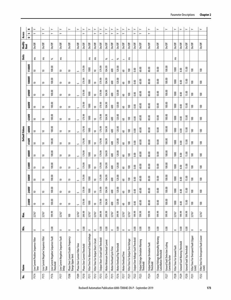
Parameter Descriptions Chapter 2
P174
Line C
urre
nt Po
sitive
Sequ
ence
Filte
r Tim
e0
3276
710
1010
1010
1010
1010
1010
10m
sOn
/Off
YY
P175
Line C
urre
nt N
egat
ive Se
quen
ce Fi
lter
Time
032
767
1010
1010
1010
1010
1010
1010
ms
On/O
ffY
Y
P176
Line C
urre
nt N
egat
ive Se
quen
ce Fa
ult
Thre
shold
0.00
199.9
910
0.00
100.0
010
0.00
100.0
010
0.00
100.0
010
0.00
100.0
010
0.00
100.0
010
0.00
100.0
0%
On/O
ffY
Y
P177
Line C
urre
nt N
egat
ive Se
quen
ce Fa
ult
Delay
032
767
1010
1010
1010
1010
1010
1010
ms
On/O
ffY
Y
P208
Phas
e Ove
r Cur
rent
Enab
le Fre
quen
cy
Rang
e Upp
er lim
it0
100
1010
1010
1010
1010
1010
1010
On/O
ffY
P209
Phas
e Ove
r Cur
rent
Filte
r Tim
e0
3276
75
55
55
55
55
55
5On
/Off
Y
P210
Phas
e Ove
r Cur
rent
Thre
shold
0.00
399.9
917
9.99
179.9
917
9.99
179.9
917
9.99
179.9
917
9.99
179.9
917
9.99
179.9
917
9.99
179.9
9On
/Off
YY
P211
Filte
r Tim
e For
Abno
rmal
Outp
ut Vo
ltage
032
767
1000
1000
1000
1000
1000
1000
1000
1000
1000
1000
1000
1000
ms
On/O
ffY
P212
Filte
r Tim
e For
Out
put S
hort-
Circu
it0
3276
710
1010
1010
1010
1010
1010
10m
sOn
/Off
YY
P213
Outp
ut Sh
ort-C
ircuit
Fault
Thre
shold
0.00
399.9
917
9.99
179.9
917
9.99
179.9
917
9.99
179.9
917
9.99
179.9
917
9.99
179.9
917
9.99
179.9
9On
/Off
YY
P214
Mot
or M
inim
um O
verlo
ad Cu
rrent
0.00
399.9
910
4.99
104.9
910
4.99
104.9
910
4.99
104.9
910
4.99
104.9
910
4.99
104.9
910
4.99
104.9
9%
On/O
ffY
Y
P215
Mot
or O
verlo
ad Cy
cle Ti
me
032
767
600
600
600
600
600
600
600
600
600
600
600
600
sOn
/Off
YY
P216
Mot
or O
verlo
ad Tr
ip Th
resh
old0.0
039
9.99
120.0
012
0.00
120.0
012
0.00
120.0
012
0.00
120.0
012
0.00
120.0
012
0.00
120.0
012
0.00
%On
/Off
YY
P217
Mot
or O
verlo
ad Ti
me
032
767
6060
6060
6060
6060
6060
6060
sOn
/Off
YY
P221
Filte
r Tim
e For
Out
put O
ver V
oltag
e0
3276
710
010
010
010
010
010
010
010
010
010
010
010
0m
sOn
/Off
Y
P222
Outp
ut O
ver V
oltag
e Fau
lt Thr
esho
ld0.0
019
9.99
0.00
0.00
0.00
0.00
0.00
0.00
0.00
0.00
0.00
0.00
0.00
0.00
On/O
ffY
Y
P223
Outp
ut Vo
ltage
Dev
iation
War
ning
Thre
shold
0.00
199.9
960
.0060
.0060
.0060
.0060
.0060
.0060
.0060
.0060
.0060
.0060
.0060
.00On
/Off
YY
P224
Outp
ut Vo
ltage
Dev
iation
Fault
Th
resh
old0.0
019
9.99
80.00
80.00
80.00
80.00
80.00
80.00
80.00
80.00
80.00
80.00
80.00
80.00
On/O
ffY
Y
P226
Outp
ut Vo
ltage
Abno
rmali
ty W
arnin
g Ca
ncell
ation
Thre
shold
0.00
199.9
950
.0050
.0050
.0050
.0050
.0050
.0050
.0050
.0050
.0050
.0050
.0050
.00On
/Off
Y
P227
Grou
nd Fa
ult D
etec
tion S
calin
g Co
rrecti
on Fa
ctor
0.00
199.9
910
0.00
100.0
010
0.00
100.0
010
0.00
100.0
010
0.00
100.0
010
0.00
100.0
010
0.00
100.0
0On
/Off
Y
P228
Filte
r Tim
e For
Gro
und F
ault
032
767
1000
1000
1000
1000
1000
1000
1000
1000
1000
1000
1000
1000
ms
On/O
ffY
P229
Grou
nd Fa
ult W
arnin
g Thr
esho
ld0.0
019
9.99
8.00
8.00
8.00
8.00
8.00
8.00
8.00
8.00
8.00
8.00
8.00
8.00
On/O
ffY
P230
Grou
nd Fa
ult Tr
ip Th
resh
old0.0
019
9.99
15.00
15.00
15.00
15.00
15.00
15.00
15.00
15.00
15.00
15.00
15.00
15.00
On/O
ffY
P231
Filte
r Tim
e For
Ove
rspee
d Fau
lt (U
pper
Lim
it)0
3276
710
010
010
010
010
010
010
010
010
010
010
010
0On
/Off
Y
P232
Filte
r Tim
e For
Ove
rspee
d Fau
lt (Lo
wer
Limit)
032
767
100
100
100
100
100
100
100
100
100
100
100
100
On/O
ffY
No.
Nam
eM
in.
Max
.De
faul
t Val
ues
Units
Mod
ify
Root
Acce
ss
2300
V24
00V
3000
V33
00V
4000
V41
60V
6000
V63
00V
6600
V69
00V
1000
0V11
000V
US
R
Rockwell Automation Publication 6000-TD004E-EN-P - September 2019 173

Chapter 2 Parameter Descriptions
P233
Thre
shold
Of O
ver-S
peed
Fault
At Lo
wer
Frequ
ency
Lim
it0.0
019
9.99
20.00
20.00
20.00
20.00
20.00
20.00
20.00
20.00
20.00
20.00
20.00
20.00
On/O
ffY
P234
Thre
shold
Of O
ver-S
peed
Fault
At U
pper
Fre
quen
cy Li
mit
0.00
199.9
920
.0020
.0020
.0020
.0020
.0020
.0020
.0020
.0020
.0020
.0020
.0020
.00On
/Off
Y
P235
Frequ
ency
Dev
iation
War
ning
Canc
ellat
ion Th
resh
old0.0
019
9.99
0.99
0.99
0.99
0.99
0.99
0.99
0.99
0.99
0.99
0.99
0.99
0.99
On/O
ffY
P236
Frequ
ency
Dev
iation
War
ning T
hres
hold
0.00
199.9
96.0
06.0
06.0
06.0
06.0
06.0
06.0
06.0
06.0
06.0
06.0
06.0
0On
/Off
Y
P237
Frequ
ency
Dev
iation
War
ning D
elay
032
767
88
88
88
88
88
8m
sOn
/Off
Y
P238
Mot
or St
all Fa
ult T
hres
hold
0.00
199.9
910
.0010
.0010
.0010
.0010
.0010
.0010
.0010
.0010
.0010
.0010
.0010
.00On
/Off
YY
P239
Mot
or St
all Fa
ult D
elay
032
767
6000
6000
6000
6000
6000
6000
6000
6000
6000
6000
6000
6000
ms
On/O
ffY
P240
Trans
form
er O
ver T
empe
ratu
re Fa
ult
Delay
032
767
1010
1010
1010
1010
1010
1010
ms
On/O
ffY
P241
Trans
form
er O
ver T
empe
ratu
re W
arnin
g De
lay0
3276
710
1010
1010
1010
1010
1010
10m
sOn
/Off
Y
P254
DC Bu
s Und
er Vo
ltage
Faul
t Thr
esho
ld0
100
6363
6363
6363
6363
6363
6363
%On
/Off
Y
P256
Grou
nd Fa
ult W
arnin
g Can
cella
tion
Thre
shold
0.00
199.9
95.0
05.0
05.0
05.0
05.0
05.0
05.0
05.0
05.0
05.0
05.0
05.0
0On
/Off
Y
P257
Mot
or St
all W
arnin
g Can
cella
tion
Thre
shold
0.00
199.9
92.9
82.9
82.9
82.9
82.9
82.9
82.9
82.9
82.9
82.9
82.9
82.9
8On
/Off
Y
P258
DC Bu
s Und
er Vo
ltage
Fault
Dela
y0
3276
710
0010
0010
0010
0010
0010
0010
0010
0010
0010
0010
0010
00m
sOn
/Off
Y
P266
DC Bu
s Volt
age D
eviat
ion Fa
ult T
hres
hold
010
025
2525
2525
2525
2525
2525
25%
On/O
ffY
Y
P267
DC Bu
s Volt
age D
eviat
ion Fa
ult Fi
lter
Time
010
0010
1010
1010
1010
1010
1010
10m
sOn
/Off
YY
P274
DC Bu
s Und
er Vo
ltage
War
ning T
hres
hold
010
080
8080
8080
8080
8080
8080
80%
On/O
ffY
Y
P275
DC Bu
s Und
er Vo
ltage
War
ning
Hyste
resis
Band
010
05
55
55
55
55
55
5%
On/O
ffY
Y
P411
Over
Spee
d Low
er Li
mit R
efere
nce
010
010
010
010
010
010
010
010
010
010
010
010
010
0On
/Off
Y
P412
Over
Spee
d Low
er Li
mit
Refe
renc
e0
100
00
00
00
00
00
00
On/O
ffY
No.
Nam
eM
in.
Max
.De
faul
t Val
ues
Units
Mod
ify
Root
Acce
ss
2300
V24
00V
3000
V33
00V
4000
V41
60V
6000
V63
00V
6600
V69
00V
1000
0V11
000V
US
R
174 Rockwell Automation Publication 6000-TD004E-EN-P - September 2019
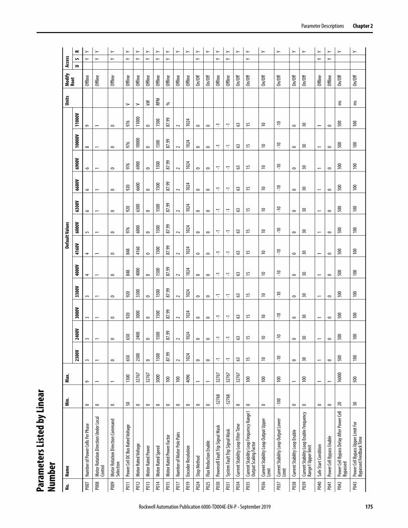
Parameter Descriptions Chapter 2
Para
met
ers L
isted
by Li
near
Nu
mbe
rNo
.Na
me
Min
.M
ax.
Defa
ult V
alue
sUn
itsM
odify
Ro
otAc
cess
2300
V24
00V
3000
V33
00V
4000
V41
60V
6000
V63
00V
6600
V69
00V
1000
0V11
000V
US
R
P007
Num
ber o
f Pow
er Ce
lls Pe
r Pha
se0
93
33
34
45
66
68
9Of
fline
YY
P008
Mot
or Ro
tatio
n Dire
ction
Und
er Lo
cal
Cont
rol
01
11
11
11
11
11
11
Offli
neY
Y
P009
Mot
or Ro
tatio
n Dire
ction
Com
man
d Se
lectio
n0
10
00
00
00
00
00
0Of
fline
YY
P011
Powe
r Cell
DC B
us Ra
ted V
oltag
e50
1300
650
650
920
920
848
848
976
920
920
976
976
976
VOf
fline
YY
P012
Mot
or Ra
ted V
oltag
e0
3276
723
0024
0030
0033
0040
0041
6060
0063
0066
0069
0010
000
1100
0V
Offli
neY
Y
P013
Mot
or Ra
ted P
ower
032
767
00
00
00
00
00
00
kWOf
fline
YY
P014
Mot
or Ra
ted S
peed
050
0015
0015
0015
0015
0015
0015
0015
0015
0015
0015
0015
0015
00RP
MOf
fline
YY
P015
Mot
or Ra
ted P
ower
Facto
r0
100
87.99
87.99
87.99
87.99
87.99
87.99
87.99
87.99
87.99
87.99
87.99
87.99
%Of
fline
YY
P017
Num
ber o
f Mot
or Po
le Pa
irs0
100
22
22
22
22
22
22
Offli
neY
P019
Enco
der R
esolu
tion
040
9610
2410
2410
2410
2410
2410
2410
2410
2410
2410
2410
2410
24Of
fline
Y
P024
Stop
Met
hod
01
00
00
00
00
00
00
On/O
ffY
Y
P025
Flux R
educ
tion E
nable
01
00
00
00
00
00
00
On/O
ffY
P030
Powe
rcell F
ault T
rip Si
gnal
Mas
k-3
2768
3276
7-1
-1-1
-1-1
-1-1
-1-1
-1-1
-1Of
fline
YY
P031
Syste
m Fa
ult T
rip Si
gnal
Mas
k-3
2768
3276
7-1
-1-1
-1-1
-1-1
-1-1
-1-1
-1Of
fline
YY
P034
Curre
nt St
abilit
y Loo
p Filt
er Ti
me
032
767
6363
6363
6363
6363
6363
6363
On/O
ffY
P035
Curre
nt St
abilit
y Loo
p Fre
quen
cy Ra
nge1
Ou
tput
Scali
ng Fa
ctor
010
015
1515
1515
1515
1515
1515
15On
/Off
YY
P036
Curre
nt St
abilit
y Loo
p Out
put U
pper
Lim
it0
100
1010
1010
1010
1010
1010
1010
On/O
ffY
P037
Curre
nt St
abilit
y Loo
p Out
put L
ower
Lim
it-1
0010
0-1
0-1
0-1
0-1
0-1
0-1
0-1
0-1
0-1
0-1
0-1
0-1
0On
/Off
Y
P038
Curre
nt St
abilit
y Loo
p Ena
ble0
10
00
00
00
00
00
0On
/Off
Y
P039
Curre
nt St
abilit
y Loo
p Ena
ble Fr
eque
ncy
Rang
e1 U
pper
limit
010
030
3030
3030
3030
3030
3030
30On
/Off
Y
P040
Safe
Star
t Con
dition
01
11
11
11
11
11
11
Offli
neY
Y
P041
Powe
r Cell
Bypa
ss En
able
01
00
00
00
00
00
00
Offli
neY
Y
P042
Powe
r Cell
Bypa
ss De
lay Af
ter P
ower
Cell
Bypa
ssed
2016
000
500
500
500
500
500
500
500
500
500
500
500
500
ms
On/O
ffY
P043
Powe
r Cell
Bypa
ss Up
per L
imit
For
Bypa
ssed F
eedb
ack T
ime
3050
010
010
010
010
010
010
010
010
010
010
010
010
0m
sOn
/Off
Y
Rockwell Automation Publication 6000-TD004E-EN-P - September 2019 175

Chapter 2 Parameter Descriptions
P044
Powe
r Cell
Bypa
ss Fa
ult Si
mula
tion
Powe
r Cell
Coun
t0
30
00
00
00
00
00
0On
/Off
YY
P045
Load
Loss
Cont
rol E
nable
01
00
00
00
00
00
00
On/O
ffY
Y
P046
Load
Loss
Enab
le Fre
quen
cy0
100
2020
2020
2020
2020
2020
2020
%On
/Off
YY
P047
Load
Loss
Cont
rol D
iffer
entia
l Sca
ling
020
008
88
88
88
88
88
8%
On/O
ffY
P048
Load
Loss
Frequ
ency
Com
pens
ation
Up
per L
imit
05
55
55
55
55
55
55
%On
/Off
YY
P049
Load
Loss
Cont
rol S
calin
g Fac
tor
020
000
00
00
00
00
00
0%
On/O
ffY
P050
Load
Loss
Cont
rol In
tegr
al Tim
e0
100
00
00
00
00
00
00
ms
On/O
ffY
P051
Load
Loss
Cont
rol F
ilter
Tim
e0
200
100
100
100
100
100
100
100
100
100
100
100
100
ms
On/O
ffY
P052
Load
Loss
Enab
le Cu
rrent
Thre
shold
010
010
1010
1010
1010
1010
1010
10%
On/O
ffY
P053
Load
Loss
Cont
rol E
xit D
elay
016
000
5000
5000
5000
5000
5000
5000
5000
5000
5000
5000
5000
5000
ms
On/O
ffY
P057
Powe
r Cell
Bypa
ss Up
per L
imit T
ime F
or
Over
Tem
pera
ture
032
767
1010
1010
1010
1010
1010
1010
sOn
/Off
Y
P058
Powe
r Cell
Bypa
ss Ph
ase A
Cell N
umbe
r Fo
r Sim
ulat
ion0
90
00
00
00
00
00
0On
/Off
YY
P059
Powe
r Cell
Bypa
ss Ph
ase B
Cell N
umbe
r Fo
r Sim
ulat
ion0
180
00
00
00
00
00
0On
/Off
YY
P060
Powe
r Cell
Bypa
ss Ph
ase C
Cell N
umbe
r Fo
r Sim
ulat
ion0
270
00
00
00
00
00
0On
/Off
YY
P061
Powe
r Cell
Bypa
ss Fa
ult S
imul
ation
-327
6832
767
00
00
00
00
00
00
On/O
ffY
Y
P065
Powe
r Cell
Bypa
ss En
able
Frequ
ency
Ra
nge L
ower
limit
0.00
19.99
0.00
0.00
0.00
0.00
0.00
0.00
0.00
0.00
0.00
0.00
0.00
0.00
On/O
ffY
P066
Powe
r Cell
Bypa
ss Re
start
Enab
le Af
ter
Powe
r Cell
Bypa
ssed
01
11
11
11
11
11
11
Offli
neY
P068
One P
hase
Lost
Filte
r Tim
e 5
1000
3030
3030
3030
3030
3030
3030
10 m
sOn
/Off
YY
P069
Curre
nt St
abilit
y Loo
p Ena
ble Fr
eque
ncy
Rang
e2 U
pper
Lim
it0
100
8080
8080
8080
8080
8080
8080
On/O
ffY
P070
Curre
nt St
abilit
y Loo
p Fre
quen
cy Ra
nge2
Ou
tput
Scali
ng Fa
ctor
010
00
00
00
00
00
00
0On
/Off
Y
P071
Curre
nt St
abilit
y Loo
p Fre
quen
cy Ra
nge3
Ou
tput
Scali
ng Fa
ctor
010
00
00
00
00
00
00
0On
/Off
Y
P072
Curre
nt St
abilit
y Loo
p Ena
ble D
elay
016
310
1010
1010
1010
1010
1010
10On
/Off
YY
Y
P073
Inpu
t Volt
age L
oss F
ilter
Tim
e0
1000
00
00
00
00
00
00
ms
On/O
ffY
P078
Powe
r Cell
Reac
tivat
ion Ti
me U
pper
Lim
it 0
200
100
100
100
100
100
100
100
100
100
100
100
100
ms
On/O
ffY
P079
VFD
Mini
mum
Ove
rload
Curre
nt0.0
039
9.99
100.0
010
0.00
100.0
010
0.00
100.0
010
0.00
100.0
010
0.00
100.0
010
0.00
100.0
010
0.00
%On
/Off
YY
No.
Nam
eM
in.
Max
.De
faul
t Val
ues
Units
Mod
ify
Root
Acce
ss
2300
V24
00V
3000
V33
00V
4000
V41
60V
6000
V63
00V
6600
V69
00V
1000
0V11
000V
US
R
176 Rockwell Automation Publication 6000-TD004E-EN-P - September 2019
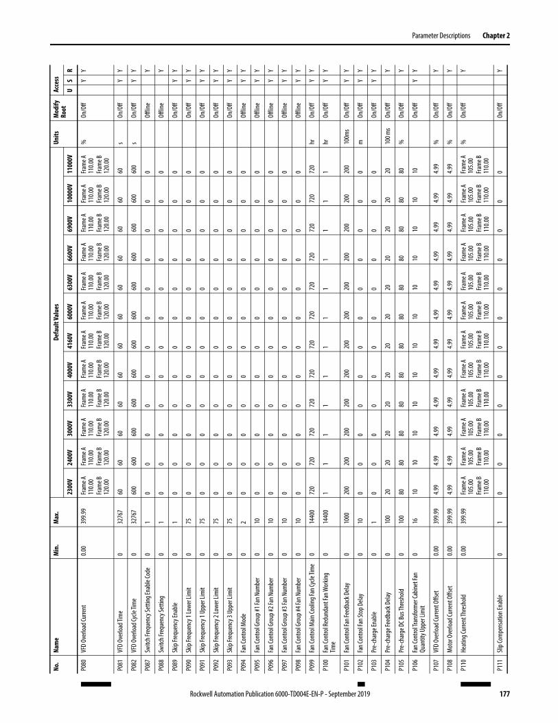
Parameter Descriptions Chapter 2
P080
VFD
Over
load C
urre
nt0.0
039
9.99
Fram
e A
110.0
0Fra
me B
12
0.00
Fram
e A
110.0
0Fra
me B
12
0.00
Fram
e A
110.0
0Fra
me B
12
0.00
Fram
e A
110.0
0Fra
me B
12
0.00
Fram
e A
110.0
0Fra
me B
12
0.00
Fram
e A
110.0
0Fra
me B
12
0.00
Fram
e A
110.0
0Fra
me B
12
0.00
Fram
e A
110.0
0Fra
me B
12
0.00
Fram
e A
110.0
0Fra
me B
12
0.00
Fram
e A
110.0
0Fra
me B
12
0.00
Fram
e A
110.0
0Fra
me B
12
0.00
Fram
e A
110.0
0Fra
me B
12
0.00
%On
/Off
YY
P081
VFD
Over
load T
ime
032
767
6060
6060
6060
6060
6060
6060
sOn
/Off
YY
P082
VFD
Over
load C
ycle
Time
032
767
600
600
600
600
600
600
600
600
600
600
600
600
sOn
/Off
YY
P087
Switc
h Fre
quen
cy Se
tting
Enab
le Co
de0
10
00
00
00
00
00
0Of
fline
Y
P088
Switc
h Fre
quen
cy Se
tting
01
00
00
00
00
00
00
Offli
neY
P089
Skip
Frequ
ency
Enab
le0
10
00
00
00
00
00
0On
/Off
YY
P090
Skip
Frequ
ency
1 Lo
wer L
imit
075
00
00
00
00
00
00
On/O
ffY
Y
P091
Skip
Frequ
ency
1 Up
per L
imit
075
00
00
00
00
00
00
On/O
ffY
Y
P092
Skip
Frequ
ency
2 Lo
wer L
imit
075
00
00
00
00
00
00
On/O
ffY
Y
P093
Skip
Frequ
ency
3 Up
per L
imit
075
00
00
00
00
00
00
On/O
ffY
Y
P094
Fan C
ontro
l Mod
e0
20
00
00
00
00
00
0Of
fline
YY
P095
Fan C
ontro
l Gro
up #1
Fan N
umbe
r0
100
00
00
00
00
00
0Of
fline
YY
P096
Fan C
ontro
l Gro
up #2
Fan N
umbe
r0
100
00
00
00
00
00
0Of
fline
YY
P097
Fan C
ontro
l Gro
up #3
Fan N
umbe
r0
100
00
00
00
00
00
0Of
fline
YY
P098
Fan C
ontro
l Gro
up #4
Fan N
umbe
r0
100
00
00
00
00
00
0Of
fline
YY
P099
Fan C
ontro
l Main
Cooli
ng Fa
n Cyc
le Tim
e0
1440
072
072
072
072
072
072
072
072
072
072
072
072
0hr
On/O
ffY
Y
P100
Fan C
ontro
l Red
unda
nt Fa
n Wor
king
Time
014
400
11
11
11
11
11
11
hrOn
/Off
YY
P101
Fan C
ontro
l Fan
Feed
back
Dela
y0
1000
200
200
200
200
200
200
200
200
200
200
200
200
100m
sOn
/Off
YY
P102
Fan C
ontro
l Fan
Stop
Dela
y0
100
00
00
00
00
00
0m
On/O
ffY
Y
P103
Pre-
char
ge En
able
01
00
00
00
00
00
00
On/O
ffY
Y
P104
Pre-
char
ge Fe
edba
ck D
elay
010
020
2020
2020
2020
2020
2020
2010
0 ms
On/O
ffY
P105
Pre-
char
ge D
C Bus
Thre
shold
010
080
8080
8080
8080
8080
8080
80%
On/O
ffY
P106
Fan C
ontro
l Tra
nsfo
rmer
Cabin
et Fa
n Qu
antit
y Upp
er Li
mit
016
1010
1010
1010
1010
1010
1010
On/O
ffY
Y
P107
VFD
Over
load C
urre
nt O
ffset
0.00
399.9
94.9
94.9
94.9
94.9
94.9
94.9
94.9
94.9
94.9
94.9
94.9
94.9
9%
On/O
ffY
P108
Mot
or O
verlo
ad Cu
rrent
Offs
et0.0
039
9.99
4.99
4.99
4.99
4.99
4.99
4.99
4.99
4.99
4.99
4.99
4.99
4.99
%On
/Off
Y
P110
Heat
ing Cu
rrent
Thre
shold
0.00
399.9
9Fra
me A
10
5.00
Fram
e B
110.0
0
Fram
e A
105.0
0Fra
me B
11
0.00
Fram
e A
105.0
0Fra
me B
11
0.00
Fram
e A
105.0
0Fra
me B
11
0.00
Fram
e A
105.0
0Fra
me B
11
0.00
Fram
e A
105.0
0Fra
me B
11
0.00
Fram
e A
105.0
0Fra
me B
11
0.00
Fram
e A
105.0
0Fra
me B
11
0.00
Fram
e A
105.0
0Fra
me B
11
0.00
Fram
e A
105.0
0Fra
me B
11
0.00
Fram
e A
105.0
0Fra
me B
11
0.00
Fram
e A
105.0
0Fra
me B
11
0.00
%On
/Off
Y
P111
Slip C
ompe
nsat
ion En
able
01
00
00
00
00
00
00
On/O
ffY
No.
Nam
eM
in.
Max
.De
faul
t Val
ues
Units
Mod
ify
Root
Acce
ss
2300
V24
00V
3000
V33
00V
4000
V41
60V
6000
V63
00V
6600
V69
00V
1000
0V11
000V
US
R
Rockwell Automation Publication 6000-TD004E-EN-P - September 2019 177
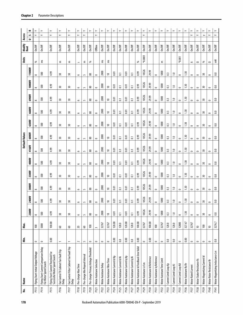
Chapter 2 Parameter Descriptions
P113
Flying
Star
t-Ini
tial O
utpu
t Volt
age
010
08
88
88
88
88
88
8%
On/O
ffY
Y
P114
Flying
Star
t-Cur
rent
Com
paris
on D
elay
For M
otor
Spee
d Sea
rch0
5000
500
500
500
500
500
500
500
500
500
500
500
500
ms
On/O
ffY
Y
P115
Flying
Star
t-Cur
rent
Thre
shold
For
Succ
essfu
l Mot
or Sp
eed S
earch
0.00
100.0
04.9
94.9
94.9
94.9
94.9
94.9
94.9
94.9
94.9
94.9
94.9
94.9
9On
/Off
YY
P116
Fan C
ontro
l TX C
abine
t Fan
Fault
Trip
Delay
160
3030
3030
3030
3030
3030
3030
mOn
/Off
YY
P117
Fan C
ontro
l Filt
er Ca
binet
Fan F
ault T
rip
Delay
160
3030
3030
3030
3030
3030
3030
mOn
/Off
YY
P118
Pre-
char
ge M
ax Ti
me
220
66
66
66
66
66
66
sOn
/Off
YY
P119
Pre-
char
ge M
in Re
peat
Inte
rval
560
55
55
55
55
55
55
mOn
/Off
YY
P120
Pre-
char
ge Pr
imar
y Volt
age T
hres
hold
010
080
8080
8080
8080
8080
8080
80%
On/O
ffY
P121
Mot
or Au
totu
ne Se
lectio
n0
30
00
00
00
00
00
0Of
fline
YY
P122
Mot
or Au
totu
ne D
elay
032
767
2000
2000
2000
2000
2000
2000
2000
2000
2000
2000
2000
2000
ms
On/O
ffY
P123
Mot
or Au
totu
ne Fi
lter T
ime
032
767
1010
1010
1010
1010
1010
1010
ms
On/O
ffY
P124
Mot
or Au
totu
ne Cu
rrent
Id Kp
0.00
128.0
00.0
10.0
10.0
10.0
10.0
10.0
10.0
10.0
10.0
10.0
10.0
10.0
1On
/Off
Y
P125
Mot
or Au
totu
ne Cu
rrent
Id Ki
0.012
8.00.1
0.10.1
0.10.1
0.10.1
0.10.1
0.10.1
0.1On
/Off
Y
P126
Mot
or Au
totu
ne Cu
rrent
Iq Kp
0.00
128.0
00.0
10.0
10.0
10.0
10.0
10.0
10.0
10.0
10.0
10.0
10.0
10.0
1On
/Off
Y
P127
Mot
or Au
totu
ne Cu
rrent
Iq Ki
0.012
8.00.1
0.10.1
0.10.1
0.10.1
0.10.1
0.10.1
0.1On
/Off
Y
P128
Mot
or Au
totu
ne Id
Feed
back
Erro
r Vali
d0.0
010
0.00
0.99
0.99
0.99
0.99
0.99
0.99
0.99
0.99
0.99
0.99
0.99
0.99
%On
/Off
Y
P129
Mot
or Au
totu
ne Lr
/Lm
032
767
1052
610
526
1052
610
526
1052
610
526
1052
610
526
1052
610
526
1052
610
526
*0.00
01On
/Off
YY
P130
Mot
or Au
totu
ne Id
Refer
ence
0.00
100.0
029
.9929
.9929
.9929
.9929
.9929
.9929
.9929
.9929
.9929
.9929
.9929
.99On
/Off
Y
P131
Mot
or Au
totu
ne Iq
Refer
ence
010
00
00
00
00
00
00
0On
/Off
Y
P132
Mot
or Au
totu
ne Ti
me L
imit
032
767
5000
5000
5000
5000
5000
5000
5000
5000
5000
5000
5000
5000
mOn
/Off
Y
P133
Curre
nt Li
mit
Loop
Kp0.0
128.0
0.30.3
0.30.3
0.30.3
0.30.3
0.30.3
0.30.3
On/O
ffY
P134
Curre
nt Li
mit
Loop
Ki0.0
128.0
1.01.0
1.01.0
1.01.0
1.01.0
1.01.0
1.01.0
On/O
ffY
P135
Curre
nt Li
mit
Loop
Kd0
1280
00
00
00
00
00
00
0*0
.001
On/O
ffY
P136
Mot
or Au
totu
ne Rs
/Rr
0.00
327.6
71.3
01.3
01.3
01.3
01.3
01.3
01.3
01.3
01.3
01.3
01.3
01.3
0On
/Off
Y
P137
Mot
or Ra
ted C
urre
nt0
3276
70
00
00
00
00
00
0A
On/O
ffY
Y
P138
Mot
or St
ator
Resis
tanc
e Rs
010
00
00
00
00
00
00
ΩOn
/Off
YY
P139
Mot
or M
agne
tizin
g Cur
rent
Id0
100
3030
3030
3030
3030
3030
3030
%On
/Off
yY
P140
Mot
or Ro
tor R
esist
ance
Rr0
100
00
00
00
00
00
0Ω
On/O
ffY
Y
P141
Mot
or M
agne
tizin
g Ind
ucta
nce L
m0.0
3276
.70.0
0.00.0
0.00.0
0.00.0
0.00.0
0.00.0
0.0m
HOn
/Off
YY
No.
Nam
eM
in.
Max
.De
faul
t Val
ues
Units
Mod
ify
Root
Acce
ss
2300
V24
00V
3000
V33
00V
4000
V41
60V
6000
V63
00V
6600
V69
00V
1000
0V11
000V
US
R
178 Rockwell Automation Publication 6000-TD004E-EN-P - September 2019

Parameter Descriptions Chapter 2
P142
Mot
or St
ator
Leak
age I
nduc
tanc
e LIs
0.032
76.7
0.00.0
0.00.0
0.00.0
0.00.0
0.00.0
0.00.0
mH
On/O
ffY
Y
P143
Mot
or Ro
tor L
eaka
ge In
ducta
nce L
lr0.0
3276
.70.0
0.00.0
0.00.0
0.00.0
0.00.0
0.00.0
0.0m
HOn
/Off
YY
P145
Syste
m Fa
ult B
Trip
Signa
l Mas
k-3
2768
3276
7-1
-1-1
-1-1
-1-1
-1-1
-1-1
-1Of
fline
YY
P146
Line R
ated
Volta
ge0
3276
723
0024
0030
0033
0040
0041
6060
0063
0066
0069
0010
000
1100
0V
On/O
ffY
Y
P147
Line R
ated
Freq
uenc
y0
3276
750
5050
5050
5050
5050
5050
50Hz
On/O
ffY
Y
P148
Trans
form
er Ra
ted P
ower
032
767
00
00
00
00
00
00
kVA
On/O
ffY
Y
P149
Trans
form
er Sh
ort C
ircuit
Impe
danc
e0
100
55
55
55
55
55
55
%On
/Off
YY
P151
Line V
oltag
e Uab
Scali
ng Fa
ctor
0.00
199.9
915
3.00
146.7
017
5.90
159.9
017
5.80
169.0
014
6.50
167.4
015
9.80
152.8
015
8.10
143.7
0%
On/O
ffY
Y
P152
Line V
oltag
e Ubc
Scali
ng Fa
ctor
0.00
199.9
915
3.00
146.7
017
5.90
159.9
017
5.80
169.0
014
6.50
167.4
015
9.80
152.8
015
8.10
143.7
0%
On/O
ffY
Y
P153
Line V
oltag
e Ung
Scali
ng Fa
ctor
0.00
199.9
910
0.00
100.0
010
0.00
100.0
010
0.00
100.0
010
0.00
100.0
010
0.00
100.0
010
0.00
100.0
0%
On/O
ffY
Y
P154
Line O
ver V
oltag
e Fau
lt Thr
esho
ld0.0
019
9.99
115.0
011
5.00
115.0
011
5.00
115.0
011
5.00
115.0
011
5.00
115.0
011
5.00
115.0
011
5.00
%On
/Off
YY
P155
Line O
ver V
oltag
e Fau
lt De
lay0
3276
710
1010
1010
1010
1010
1010
10m
sOn
/Off
YY
P156
Line U
nder
Volta
ge W
arni
ng Th
resh
old0
100
8080
8080
8080
8080
8080
8080
%On
/Off
YY
P157
Line U
nder
Volta
ge W
arnin
g Dela
y0
3276
710
0010
0010
0010
0010
0010
0010
0010
0010
0010
0010
0010
00m
sOn
/Off
YY
P158
Line N
eutra
l Ove
r Volt
age W
arni
ng
Thre
shold
0.00
199.9
960
.0060
.0060
.0060
.0060
.0060
.0060
.0060
.0060
.0060
.0060
.0060
.00%
On/O
ffY
Y
P159
Line N
eutra
l Ove
r Volt
age W
arnin
g Dela
y0
3276
710
0010
0010
0010
0010
0010
0010
0010
0010
0010
0010
0010
00m
sOn
/Off
YY
P160
Line N
eutra
l Ove
r Volt
age F
ault
Thre
shold
0.00
199.9
980
.0080
.0080
.0080
.0080
.0080
.0080
.0080
.0080
.0080
.0080
.0080
.00%
On/O
ffY
Y
P161
Line N
eutra
l Ove
r Volt
age F
ault
Delay
032
767
1000
1000
1000
1000
1000
1000
1000
1000
1000
1000
1000
1000
ms
On/O
ffY
Y
P162
Line V
oltag
e Pos
itive
Sequ
ence
Filte
r Tim
e0
3276
710
1010
1010
1010
1010
1010
10m
sOn
/Off
YY
P163
Line V
oltag
e Neg
ative
Sequ
ence
Filte
r Tim
e 0
3276
710
1010
1010
1010
1010
1010
10m
sOn
/Off
YY
P164
Line V
oltag
e Neg
ative
Sequ
ence
Fault
Th
resh
old0.0
019
9.99
20.00
20.00
20.00
20.00
20.00
20.00
20.00
20.00
20.00
20.00
20.00
20.00
%On
/Off
YY
P165
Line V
oltag
e Neg
ative
Sequ
ence
Fault
De
lay0
3276
710
1010
1010
1010
1010
1010
10m
sOn
/Off
YY
P166
Line V
oltag
e Pha
ser S
eque
nce R
ever
se
Enab
le0
10
00
00
00
00
00
0On
/Off
YY
P168
Line C
urre
nt Fi
lter T
ime
032
767
1010
1010
1010
1010
1010
1010
ms
On/O
ffY
Y
P169
Line S
hort
Circu
it Fa
ult Th
resh
old0
400
180
180
180
180
180
180
180
180
180
180
180
180
%On
/Off
YY
P170
Line S
hort
Circu
it Fau
lt De
lay0
3276
710
1010
1010
1010
1010
1010
10m
sOn
/Off
YY
P171
Line C
urre
nt Ph
ase A
Scali
ng Fa
ctor
0.00
199.9
910
0.00
100.0
010
0.00
100.0
010
0.00
100.0
010
0.00
100.0
010
0.00
100.0
010
0.00
100.0
0%
On/O
ffY
No.
Nam
eM
in.
Max
.De
faul
t Val
ues
Units
Mod
ify
Root
Acce
ss
2300
V24
00V
3000
V33
00V
4000
V41
60V
6000
V63
00V
6600
V69
00V
1000
0V11
000V
US
R
Rockwell Automation Publication 6000-TD004E-EN-P - September 2019 179
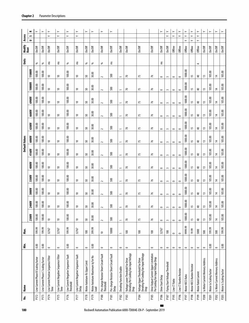
Chapter 2 Parameter Descriptions
P172
Line C
urre
nt Ph
ase B
Scali
ng Fa
ctor
0.00
199.9
910
0.00
100.0
010
0.00
100.0
010
0.00
100.0
010
0.00
100.0
010
0.00
100.0
010
0.00
100.0
0%
On/O
ffY
P173
Line C
urre
nt Ph
ase C
Scali
ng Fa
ctor
0.00
199.9
910
0.00
100.0
010
0.00
100.0
010
0.00
100.0
010
0.00
100.0
010
0.00
100.0
010
0.00
100.0
0%
On/O
ffY
P174
Line C
urre
nt Po
sitive
Sequ
ence
Filte
r Tim
e0
3276
710
1010
1010
1010
1010
1010
10m
sOn
/Off
YY
P175
Line C
urre
nt N
egat
ive Se
quen
ce Fi
lter
Time
032
767
1010
1010
1010
1010
1010
1010
ms
On/O
ffY
Y
P176
Line C
urre
nt N
egat
ive Se
quen
ce Fa
ult
Thre
shold
0.00
199.9
910
0.00
100.0
010
0.00
100.0
010
0.00
100.0
010
0.00
100.0
010
0.00
100.0
010
0.00
100.0
0%
On/O
ffY
Y
P177
Line C
urre
nt N
egat
ive Se
quen
ce Fa
ult
Delay
032
767
1010
1010
1010
1010
1010
1010
ms
On/O
ffY
Y
P178
Mot
or Au
totu
ne Rs
Upp
er Li
mit
010
050
5050
5050
5050
5050
5050
50%
On/O
ffY
P179
Mot
or Au
totu
ne M
axim
um Iq
For N
o Lo
ad0.0
039
9.99
30.00
30.00
30.00
30.00
30.00
30.00
30.00
30.00
30.00
30.00
30.00
30.00
%On
/Off
Y
P180
Pre-
char
ge Re
sisto
r Sho
rt Cir
cuit
Fault
Th
resh
old0
102
22
22
22
22
22
2%
On/O
ffY
P181
Pre-
char
ge Re
sisto
r Sho
rt Cir
cuit
Fault
De
lay0
1000
050
050
050
050
050
050
050
050
050
050
050
050
0m
sOn
/Off
Y
P182
Dera
ting F
uncti
on En
able
01
11
11
11
11
11
11
On/O
ff
P183
Volta
ge Lo
wer T
hres
hold
For D
rive
Dera
ting P
er Co
oling
Fan I
nput
Volta
ge
Drop
010
070
7070
7070
7070
7070
7070
70On
/Off
P184
Volta
ge U
pper
Thre
shold
For D
rive
Dera
ting P
er Co
oling
Fan I
nput
Volta
ge
Drop
010
075
7575
7575
7575
7575
7575
75On
/Off
P185
Drive
Out
put C
urre
nt U
pper
Lim
itatio
n Pe
r Coo
ling F
an In
put V
oltag
e Dro
p0
100
7676
7676
7676
7676
7676
7676
On/O
ff
P186
Drive
Star
t Dela
y0
3276
70
00
00
00
00
00
0m
sOn
/Off
Y
P187
Flying
Star
t Volt
age T
hres
hold
010
03
33
33
33
33
33
3On
/Off
YY
P195
Line C
T Rat
io0
00
00
00
00
00
00
0Of
fline
YY
P196
Line C
T Bur
den R
esist
or0
00
00
00
00
00
00
0Of
fline
YY
P197
Mot
or H
ECS R
atio
099
99.99
1000
.0010
00.00
1000
.0010
00.00
1000
.0010
00.00
1000
.0010
00.00
1000
.0010
00.00
1000
.0010
00.00
Offli
neY
YY
P198
Mot
or H
ECS B
urde
n Res
istor
019
.9915
1515
1515
1515
1515
1515
15Of
fline
YY
Y
P199
Mot
or Ra
ted C
urre
nt0
5000
4040
4040
4040
4040
4040
4040
AOf
fline
YY
Y
P200
Ia M
otor
Curre
nt M
emor
y Add
ress
050
013
1313
1313
1313
1313
1313
13On
/Off
Y
P201
Mot
or Ia
Scali
ng Fa
ctor
0.00
199.9
910
5.00
105.0
010
5.00
105.0
010
5.00
105.0
010
5.00
105.0
010
5.00
105.0
010
5.00
105.0
0On
/Off
Y
P202
Ic M
otor
Curre
nt M
emor
y Add
ress
050
014
1414
1414
1414
1414
1414
14On
/Off
Y
P203
Mot
or Ic
Scali
ng Fa
ctor
0.00
199.9
910
5.00
105.0
010
5.00
105.0
010
5.00
105.0
010
5.00
105.0
010
5.00
105.0
010
5.00
105.0
0On
/Off
Y
No.
Nam
eM
in.
Max
.De
faul
t Val
ues
Units
Mod
ify
Root
Acce
ss
2300
V24
00V
3000
V33
00V
4000
V41
60V
6000
V63
00V
6600
V69
00V
1000
0V11
000V
US
R
180 Rockwell Automation Publication 6000-TD004E-EN-P - September 2019
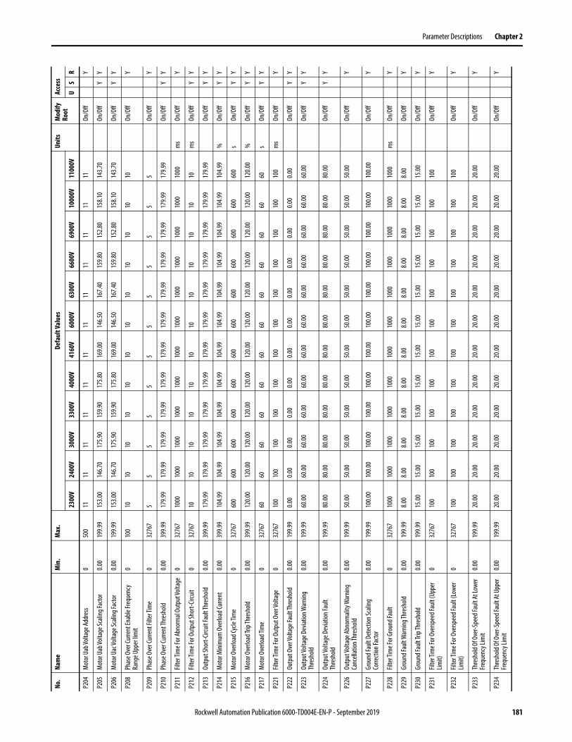
Parameter Descriptions Chapter 2
P204
Mot
or U
ab Vo
ltage
Addr
ess
050
011
1111
1111
1111
1111
1111
11On
/Off
Y
P205
Mot
or U
ab Vo
ltage
Scali
ng Fa
ctor
0.00
199.9
915
3.00
146.7
017
5.90
159.9
017
5.80
169.0
014
6.50
167.4
015
9.80
152.8
015
8.10
143.7
0On
/Off
YY
P206
Mot
or U
ac Vo
ltage
Scali
ng Fa
ctor
0.00
199.9
915
3.00
146.7
017
5.90
159.9
017
5.80
169.0
014
6.50
167.4
015
9.80
152.8
015
8.10
143.7
0On
/Off
YY
P208
Phas
e Ove
r Cur
rent
Enab
le Fre
quen
cy
Rang
e Upp
er lim
it0
100
1010
1010
1010
1010
1010
1010
On/O
ffY
P209
Phas
e Ove
r Cur
rent
Filte
r Tim
e0
3276
75
55
55
55
55
55
5On
/Off
Y
P210
Phas
e Ove
r Cur
rent
Thre
shold
0.00
399.9
917
9.99
179.9
917
9.99
179.9
917
9.99
179.9
917
9.99
179.9
917
9.99
179.9
917
9.99
179.9
9On
/Off
YY
P211
Filte
r Tim
e For
Abno
rmal
Outp
ut Vo
ltage
032
767
1000
1000
1000
1000
1000
1000
1000
1000
1000
1000
1000
1000
ms
On/O
ffY
P212
Filte
r Tim
e For
Out
put S
hort-
Circu
it0
3276
710
1010
1010
1010
1010
1010
10m
sOn
/Off
YY
P213
Outp
ut Sh
ort-C
ircuit
Faul
t Thr
esho
ld0.0
039
9.99
179.9
917
9.99
179.9
917
9.99
179.9
917
9.99
179.9
917
9.99
179.9
917
9.99
179.9
917
9.99
On/O
ffY
Y
P214
Mot
or M
inim
um O
verlo
ad Cu
rrent
0.00
399.9
910
4.99
104.9
910
4.99
104.9
910
4.99
104.9
910
4.99
104.9
910
4.99
104.9
910
4.99
104.9
9%
On/O
ffY
Y
P215
Mot
or O
verlo
ad Cy
cle Ti
me
032
767
600
600
600
600
600
600
600
600
600
600
600
600
sOn
/Off
YY
P216
Mot
or O
verlo
ad Tr
ip Th
resh
old0.0
039
9.99
120.0
012
0.00
120.0
012
0.00
120.0
012
0.00
120.0
012
0.00
120.0
012
0.00
120.0
012
0.00
%On
/Off
YY
P217
Mot
or O
verlo
ad Ti
me
032
767
6060
6060
6060
6060
6060
6060
sOn
/Off
YY
P221
Filte
r Tim
e For
Out
put O
ver V
oltag
e0
3276
710
010
010
010
010
010
010
010
010
010
010
010
0m
sOn
/Off
Y
P222
Outp
ut O
ver V
oltag
e Fau
lt Thr
esho
ld0.0
019
9.99
0.00
0.00
0.00
0.00
0.00
0.00
0.00
0.00
0.00
0.00
0.00
0.00
On/O
ffY
Y
P223
Outp
ut Vo
ltage
Dev
iation
War
ning
Thre
shold
0.00
199.9
960
.0060
.0060
.0060
.0060
.0060
.0060
.0060
.0060
.0060
.0060
.0060
.00On
/Off
YY
P224
Outp
ut Vo
ltage
Dev
iation
Fault
Th
resh
old0.0
019
9.99
80.00
80.00
80.00
80.00
80.00
80.00
80.00
80.00
80.00
80.00
80.00
80.00
On/O
ffY
Y
P226
Outp
ut Vo
ltage
Abn
orm
ality
War
ning
Canc
ellat
ion Th
resh
old0.0
019
9.99
50.00
50.00
50.00
50.00
50.00
50.00
50.00
50.00
50.00
50.00
50.00
50.00
On/O
ffY
P227
Grou
nd Fa
ult D
etec
tion S
calin
g Co
rrecti
on Fa
ctor
0.00
199.9
910
0.00
100.0
010
0.00
100.0
010
0.00
100.0
010
0.00
100.0
010
0.00
100.0
010
0.00
100.0
0On
/Off
Y
P228
Filte
r Tim
e For
Gro
und F
ault
032
767
1000
1000
1000
1000
1000
1000
1000
1000
1000
1000
1000
1000
ms
On/O
ffY
P229
Grou
nd Fa
ult W
arnin
g Thr
esho
ld0.0
019
9.99
8.00
8.00
8.00
8.00
8.00
8.00
8.00
8.00
8.00
8.00
8.00
8.00
On/O
ffY
P230
Grou
nd Fa
ult Tr
ip Th
resh
old0.0
019
9.99
15.00
15.00
15.00
15.00
15.00
15.00
15.00
15.00
15.00
15.00
15.00
15.00
On/O
ffY
P231
Filte
r Tim
e For
Ove
rspee
d Fau
lt (U
pper
Lim
it)0
3276
710
010
010
010
010
010
010
010
010
010
010
010
0On
/Off
Y
P232
Filte
r Tim
e For
Ove
rspee
d Fau
lt (Lo
wer
Limit)
032
767
100
100
100
100
100
100
100
100
100
100
100
100
On/O
ffY
P233
Thre
shold
Of O
ver-S
peed
Faul
t At L
ower
Fre
quen
cy Li
mit
0.00
199.9
920
.0020
.0020
.0020
.0020
.0020
.0020
.0020
.0020
.0020
.0020
.0020
.00On
/Off
Y
P234
Thre
shold
Of O
ver-S
peed
Fault
At U
pper
Fre
quen
cy Li
mit
0.00
199.9
920
.0020
.0020
.0020
.0020
.0020
.0020
.0020
.0020
.0020
.0020
.0020
.00On
/Off
Y
No.
Nam
eM
in.
Max
.De
faul
t Val
ues
Units
Mod
ify
Root
Acce
ss
2300
V24
00V
3000
V33
00V
4000
V41
60V
6000
V63
00V
6600
V69
00V
1000
0V11
000V
US
R
Rockwell Automation Publication 6000-TD004E-EN-P - September 2019 181
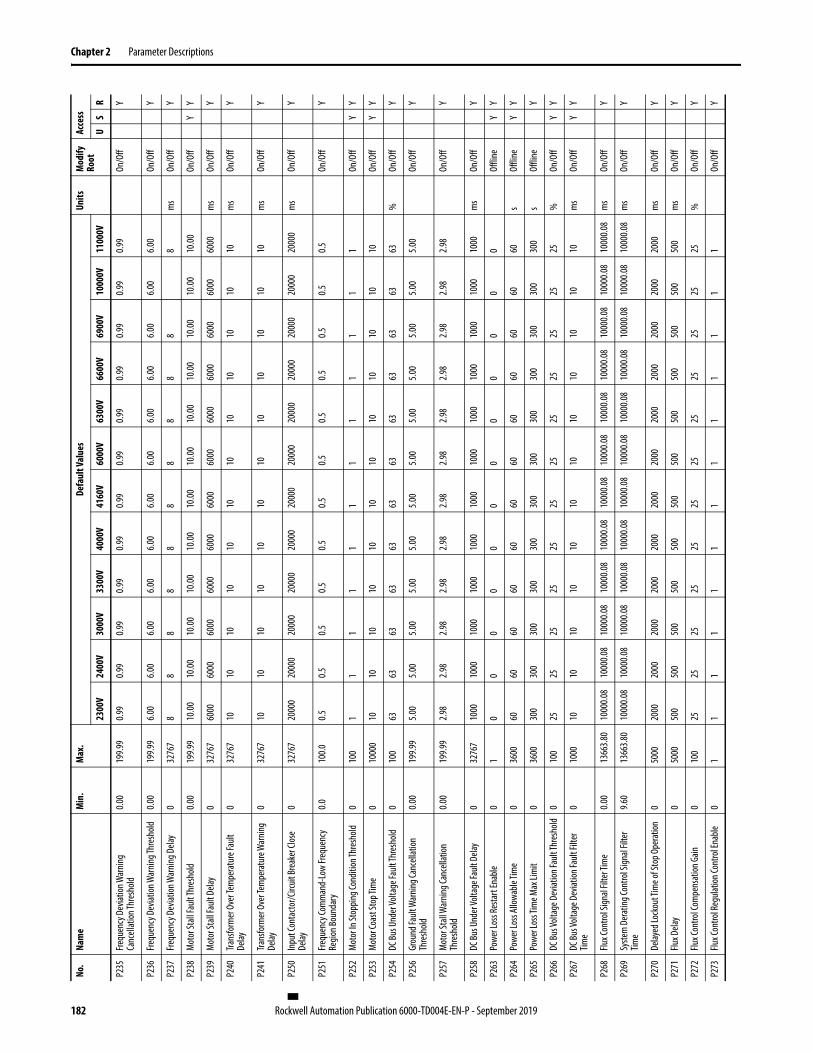
Chapter 2 Parameter Descriptions
P235
Frequ
ency
Dev
iation
War
ning
Canc
ellat
ion Th
resh
old0.0
019
9.99
0.99
0.99
0.99
0.99
0.99
0.99
0.99
0.99
0.99
0.99
0.99
0.99
On/O
ffY
P236
Frequ
ency
Dev
iation
War
ning T
hres
hold
0.00
199.9
96.0
06.0
06.0
06.0
06.0
06.0
06.0
06.0
06.0
06.0
06.0
06.0
0On
/Off
Y
P237
Frequ
ency
Dev
iation
War
ning
Dela
y0
3276
78
88
88
88
88
88
ms
On/O
ffY
P238
Mot
or St
all Fa
ult Th
resh
old0.0
019
9.99
10.00
10.00
10.00
10.00
10.00
10.00
10.00
10.00
10.00
10.00
10.00
10.00
On/O
ffY
Y
P239
Mot
or St
all Fa
ult D
elay
032
767
6000
6000
6000
6000
6000
6000
6000
6000
6000
6000
6000
6000
ms
On/O
ffY
P240
Trans
form
er O
ver T
empe
ratu
re Fa
ult
Delay
032
767
1010
1010
1010
1010
1010
1010
ms
On/O
ffY
P241
Trans
form
er O
ver T
empe
ratu
re W
arnin
g De
lay0
3276
710
1010
1010
1010
1010
1010
10m
sOn
/Off
Y
P250
Inpu
t Con
tacto
r/Circ
uit Br
eake
r Clos
e De
lay0
3276
720
000
2000
020
000
2000
020
000
2000
020
000
2000
020
000
2000
020
000
2000
0m
sOn
/Off
Y
P251
Frequ
ency
Com
man
d-Lo
w Fre
quen
cy
Regio
n Bou
ndar
y0.0
100.0
0.50.5
0.50.5
0.50.5
0.50.5
0.50.5
0.50.5
On/O
ffY
P252
Mot
or In
Stop
ping C
ondit
ion Th
resh
old0
100
11
11
11
11
11
11
On/O
ffY
Y
P253
Mot
or Co
ast S
top T
ime
010
000
1010
1010
1010
1010
1010
1010
On/O
ffY
Y
P254
DC Bu
s Und
er Vo
ltage
Fault
Thre
shold
010
063
6363
6363
6363
6363
6363
63%
On/O
ffY
P256
Grou
nd Fa
ult W
arnin
g Can
cella
tion
Thre
shold
0.00
199.9
95.0
05.0
05.0
05.0
05.0
05.0
05.0
05.0
05.0
05.0
05.0
05.0
0On
/Off
Y
P257
Mot
or St
all W
arnin
g Can
cella
tion
Thre
shold
0.00
199.9
92.9
82.9
82.9
82.9
82.9
82.9
82.9
82.9
82.9
82.9
82.9
82.9
8On
/Off
Y
P258
DC Bu
s Und
er Vo
ltage
Fault
Dela
y0
3276
710
0010
0010
0010
0010
0010
0010
0010
0010
0010
0010
0010
00m
sOn
/Off
Y
P263
Powe
r Los
s Res
tart
Enab
le0
10
00
00
00
00
00
0Of
fline
YY
P264
Powe
r Los
s Allo
wabl
e Tim
e0
3600
6060
6060
6060
6060
6060
6060
sOf
fline
YY
P265
Powe
r Los
s Tim
e Max
Lim
it0
3600
300
300
300
300
300
300
300
300
300
300
300
300
sOf
fline
Y
P266
DC Bu
s Volt
age D
eviat
ion Fa
ult T
hres
hold
010
025
2525
2525
2525
2525
2525
25%
On/O
ffY
Y
P267
DC Bu
s Volt
age D
eviat
ion Fa
ult F
ilter
Tim
e0
1000
1010
1010
1010
1010
1010
1010
ms
On/O
ffY
Y
P268
Flux C
ontro
l Sign
al Fil
ter T
ime
0.00
1366
3.80
1000
0.08
1000
0.08
1000
0.08
1000
0.08
1000
0.08
1000
0.08
1000
0.08
1000
0.08
1000
0.08
1000
0.08
1000
0.08
1000
0.08
ms
On/O
ffY
P269
Syste
m D
erat
ing Co
ntro
l Sign
al Fil
ter
Time
9.60
1366
3.80
1000
0.08
1000
0.08
1000
0.08
1000
0.08
1000
0.08
1000
0.08
1000
0.08
1000
0.08
1000
0.08
1000
0.08
1000
0.08
1000
0.08
ms
On/O
ffY
P270
Delay
ed Lo
ckou
t Tim
e of S
top O
pera
tion
050
0020
0020
0020
0020
0020
0020
0020
0020
0020
0020
0020
0020
00m
sOn
/Off
Y
P271
Flux D
elay
050
0050
050
050
050
050
050
050
050
050
050
050
050
0m
sOn
/Off
Y
P272
Flux C
ontro
l Com
pens
ation
Gain
010
025
2525
2525
2525
2525
2525
25%
On/O
ffY
P273
Flux C
ontro
l Reg
ulatio
n Con
trol E
nabl
e0
11
11
11
11
11
11
1On
/Off
Y
No.
Nam
eM
in.
Max
.De
faul
t Val
ues
Units
Mod
ify
Root
Acce
ss
2300
V24
00V
3000
V33
00V
4000
V41
60V
6000
V63
00V
6600
V69
00V
1000
0V11
000V
US
R
182 Rockwell Automation Publication 6000-TD004E-EN-P - September 2019
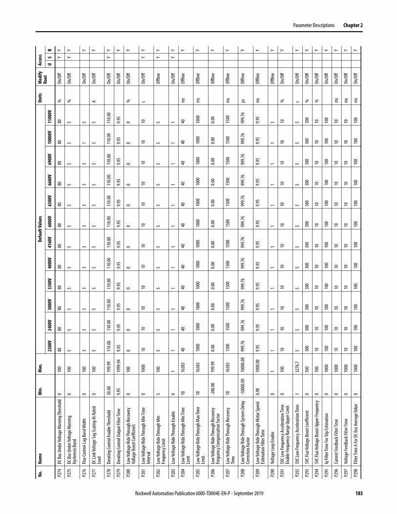
Parameter Descriptions Chapter 2
P274
DC Bu
s Und
er Vo
ltage
War
ning T
hres
hold
010
080
8080
8080
8080
8080
8080
80%
On/O
ffY
Y
P275
DC Bu
s Und
er Vo
ltage
War
ning
Hyste
resis
Band
010
05
55
55
55
55
55
5%
On/O
ffY
Y
P276
Flux C
ontro
l-Lag
Band
Widt
h0
100
33
33
33
33
33
13
On/O
ffY
P277
DC Li
nk Vo
ltage
Sag S
calin
g At R
ated
Lo
ad0
100
55
55
55
55
55
55
AOn
/Off
Y
P278
Dera
ting C
ontro
l Ena
ble Th
resh
old50
.0019
9.99
110.0
011
0.00
110.0
011
0.00
110.0
011
0.00
110.0
011
0.00
110.0
011
0.00
110.0
011
0.00
On/O
ffY
Y
P279
Dera
ting C
ontro
l Out
put F
ilter
Tim
e9.9
519
99.94
9.95
9.95
9.95
9.95
9.95
9.95
9.95
9.95
9.95
9.95
9.95
9.95
On/O
ffY
P280
Low
Volta
ge Ri
de Th
roug
h Rec
over
y Vo
ltage
Boos
t Coe
fficie
nt0
100
00
00
00
00
00
00
%On
/Off
Y
P281
Low
Volta
ge Ri
de Th
roug
h Min
Time
Inte
rval
010
0010
1010
1010
1010
1010
1010
10s
On/O
ffY
Y
P282
Low
Volta
ge Ri
de Th
roug
h Min
Frequ
ency
Lim
it5
100
55
55
55
55
55
55
Offli
neY
Y
P283
Low
Volta
ge Ri
de Th
roug
h Ena
ble
01
11
11
11
11
11
11
On/O
ffY
Y
P284
Low
Volta
ge Ri
de Th
roug
h Min
Time
Limit
1016
383
4040
4040
4040
4040
4040
4040
ms
Offli
neY
P285
Low
Volta
ge Ri
de Th
roug
h Max
Tim
e Lim
it10
1638
310
0010
0010
0010
0010
0010
0010
0010
0010
0010
0010
0010
00m
sOf
fline
Y
P286
Low
Volta
ge Ri
de Th
roug
h Rec
over
y Fre
quen
cy Co
mpe
nsat
ion Fa
ctor
-200
.0019
9.99
0.00
0.00
0.00
0.00
0.00
0.00
0.00
0.00
0.00
0.00
0.00
0.00
Offli
neY
P287
Low
Volta
ge Ri
de Th
roug
h Rec
over
y Tim
e10
1638
315
0015
0015
0015
0015
0015
0015
0015
0015
0015
0015
0015
00m
sOf
fline
Y
P288
Low
Volta
ge Ri
de Th
roug
h Sys
tem
Dela
y Co
rrecti
on Fa
ctor
-100
00.00
1000
0.00
999.7
699
9.76
999.7
699
9.76
999.7
699
9.76
999.7
699
9.76
999.7
699
9.76
999.7
699
9.76
μsOf
fline
Y
P289
Low
Volta
ge Ri
de Th
roug
h Mot
or Sp
eed
Estim
ation
Filte
r Tim
e0.9
810
00.00
9.95
9.95
9.95
9.95
9.95
9.95
9.95
9.95
9.95
9.95
9.95
9.95
ms
Offli
neY
P290
Volta
ge Lo
op En
able
01
11
11
11
11
11
11
Offli
neY
P291
SVC L
ow Fr
eque
ncy A
ccele
ratio
n Tim
e En
able
Frequ
ency
Rang
e Upp
er Li
mit
010
010
1010
1010
1010
1010
1010
10%
On/O
ffY
P292
SVC L
ow Fr
eque
ncy A
ccele
ratio
n Tim
e1
3276
.75
55
55
55
55
55
5s
On/O
ffY
P293
SVC F
lux Vo
ltage
Boos
t Coe
fficie
nt0
500
300
300
300
300
300
300
300
300
300
300
300
300
%On
/Off
Y
P294
SVC F
lux Vo
ltage
Boos
t Upp
er Fr
eque
ncy
010
010
1010
1010
1010
1010
1010
10%
On/O
ffY
P295
Iq Fi
lter T
ime F
or Sl
ip Es
timat
ion0
1000
100
100
100
100
100
100
100
100
100
100
100
100
On/O
ffY
P296
Curre
nt Fe
edba
ck Fi
lter T
ime
010
0010
1010
1010
1010
1010
1010
10m
sOn
/Off
Y
P297
Volta
ge Fe
edba
ck Fi
lter T
ime
010
0010
1010
1010
1010
1010
1010
10m
sOn
/Off
Y
P298
Filte
r Tim
e A Fo
r DC B
us Av
erag
e Valu
e0
1000
100
100
100
100
100
100
100
100
100
100
100
100
ms
On/O
ffY
No.
Nam
eM
in.
Max
.De
faul
t Val
ues
Units
Mod
ify
Root
Acce
ss
2300
V24
00V
3000
V33
00V
4000
V41
60V
6000
V63
00V
6600
V69
00V
1000
0V11
000V
US
R
Rockwell Automation Publication 6000-TD004E-EN-P - September 2019 183
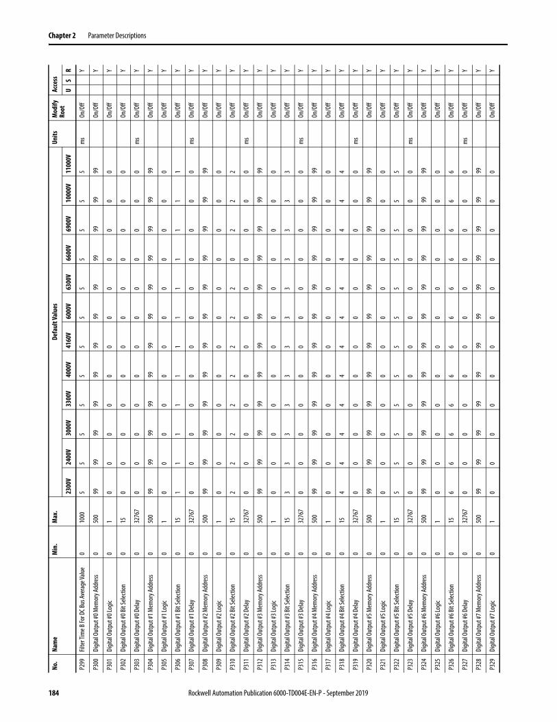
Chapter 2 Parameter Descriptions
P299
Filte
r Tim
e B Fo
r DC B
us Av
erag
e Valu
e0
1000
55
55
55
55
55
55
ms
On/O
ffY
P300
Digit
al Ou
tput
#0 M
emor
y Add
ress
050
099
9999
9999
9999
9999
9999
99On
/Off
Y
P301
Digit
al Ou
tput
#0 Lo
gic0
10
00
00
00
00
00
0On
/Off
Y
P302
Digit
al Ou
tput
#0 Bi
t Sele
ction
015
00
00
00
00
00
00
On/O
ffY
P303
Digit
al Ou
tput
#0 D
elay
032
767
00
00
00
00
00
00
ms
On/O
ffY
P304
Digit
al Ou
tput
#1 M
emor
y Add
ress
050
099
9999
9999
9999
9999
9999
99On
/Off
Y
P305
Digit
al Ou
tput
#1 Lo
gic0
10
00
00
00
00
00
0On
/Off
Y
P306
Digit
al Ou
tput
#1 Bi
t Sele
ction
015
11
11
11
11
11
11
On/O
ffY
P307
Digit
al Ou
tput
#1 D
elay
032
767
00
00
00
00
00
00
ms
On/O
ffY
P308
Digit
al Ou
tput
#2 M
emor
y Add
ress
050
099
9999
9999
9999
9999
9999
99On
/Off
Y
P309
Digit
al Ou
tput
#2 Lo
gic0
10
00
00
00
00
00
0On
/Off
Y
P310
Digit
al Ou
tput
#2 Bi
t Sele
ction
015
22
22
22
22
02
22
On/O
ffY
P311
Digit
al Ou
tput
#2 D
elay
032
767
00
00
00
00
00
00
ms
On/O
ffY
P312
Digit
al Ou
tput
#3 M
emor
y Add
ress
050
099
9999
9999
9999
9999
9999
99On
/Off
Y
P313
Digit
al Ou
tput
#3 Lo
gic0
10
00
00
00
00
00
0On
/Off
Y
P314
Digit
al Ou
tput
#3 Bi
t Sele
ction
015
33
33
33
33
33
33
On/O
ffY
P315
Digit
al Ou
tput
#3 D
elay
032
767
00
00
00
00
00
00
ms
On/O
ffY
P316
Digit
al Ou
tput
#4 M
emor
y Add
ress
050
099
9999
9999
9999
9999
9999
99On
/Off
Y
P317
Digit
al Ou
tput
#4 Lo
gic0
10
00
00
00
00
00
0On
/Off
Y
P318
Digit
al Ou
tput
#4 Bi
t Sele
ction
015
44
44
44
44
44
44
On/O
ffY
P319
Digit
al Ou
tput
#4 D
elay
032
767
00
00
00
00
00
00
ms
On/O
ffY
P320
Digit
al Ou
tput
#5 M
emor
y Add
ress
050
099
9999
9999
9999
9999
9999
99On
/Off
Y
P321
Digit
al Ou
tput
#5 Lo
gic0
10
00
00
00
00
00
0On
/Off
Y
P322
Digit
al Ou
tput
#5 Bi
t Sele
ction
015
55
55
55
55
55
55
On/O
ffY
P323
Digit
al Ou
tput
#5 D
elay
032
767
00
00
00
00
00
00
ms
On/O
ffY
P324
Digit
al Ou
tput
#6 M
emor
y Add
ress
050
099
9999
9999
9999
9999
9999
99On
/Off
Y
P325
Digit
al Ou
tput
#6 Lo
gic0
10
00
00
00
00
00
0On
/Off
Y
P326
Digit
al Ou
tput
#6 Bi
t Sele
ction
015
66
66
66
66
66
66
On/O
ffY
P327
Digit
al Ou
tput
#6 D
elay
032
767
00
00
00
00
00
00
ms
On/O
ffY
P328
Digit
al Ou
tput
#7 M
emor
y Add
ress
050
099
9999
9999
9999
9999
9999
99On
/Off
Y
P329
Digit
al Ou
tput
#7 Lo
gic0
10
00
00
00
00
00
0On
/Off
Y
No.
Nam
eM
in.
Max
.De
faul
t Val
ues
Units
Mod
ify
Root
Acce
ss
2300
V24
00V
3000
V33
00V
4000
V41
60V
6000
V63
00V
6600
V69
00V
1000
0V11
000V
US
R
184 Rockwell Automation Publication 6000-TD004E-EN-P - September 2019
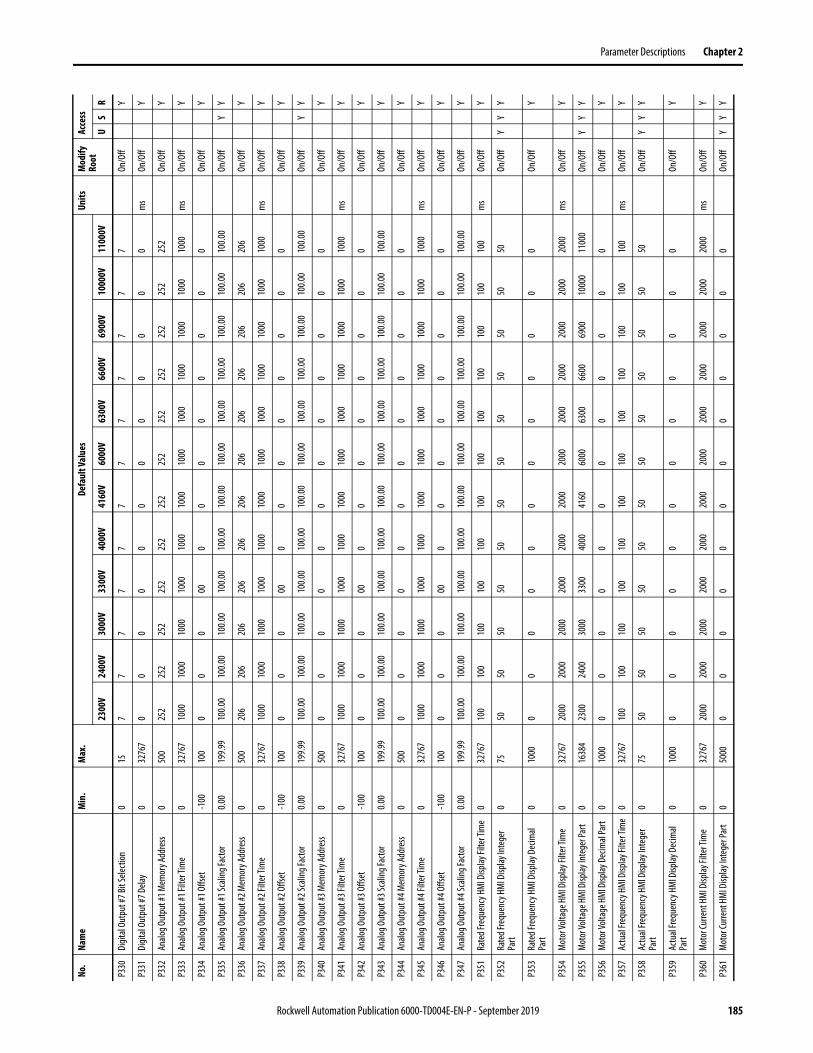
Parameter Descriptions Chapter 2
P330
Digit
al Ou
tput
#7 Bi
t Sele
ction
015
77
77
77
77
77
77
On/O
ffY
P331
Digit
al Ou
tput
#7 D
elay
032
767
00
00
00
00
00
00
ms
On/O
ffY
P332
Analo
g Out
put #
1 Mem
ory A
ddre
ss0
500
252
252
252
252
252
252
252
252
252
252
252
252
On/O
ffY
P333
Analo
g Out
put #
1 Filt
er Ti
me
032
767
1000
1000
1000
1000
1000
1000
1000
1000
1000
1000
1000
1000
ms
On/O
ffY
P334
Analo
g Out
put #
1 Offs
et-1
0010
00
00
000
00
00
00
0On
/Off
Y
P335
Analo
g Out
put #
1 Sca
ling F
acto
r0.0
019
9.99
100.0
010
0.00
100.0
010
0.00
100.0
010
0.00
100.0
010
0.00
100.0
010
0.00
100.0
010
0.00
On/O
ffY
Y
P336
Analo
g Out
put #
2 Mem
ory A
ddre
ss0
500
206
206
206
206
206
206
206
206
206
206
206
206
On/O
ffY
P337
Analo
g Out
put #
2 Filt
er Ti
me
032
767
1000
1000
1000
1000
1000
1000
1000
1000
1000
1000
1000
1000
ms
On/O
ffY
P338
Analo
g Out
put #
2 Offs
et-1
0010
00
00
000
00
00
00
0On
/Off
Y
P339
Analo
g Out
put #
2 Sca
ling F
acto
r0.0
019
9.99
100.0
010
0.00
100.0
010
0.00
100.0
010
0.00
100.0
010
0.00
100.0
010
0.00
100.0
010
0.00
On/O
ffY
Y
P340
Analo
g Out
put #
3 Mem
ory A
ddre
ss0
500
00
00
00
00
00
00
On/O
ffY
P341
Analo
g Out
put #
3 Filt
er Ti
me
032
767
1000
1000
1000
1000
1000
1000
1000
1000
1000
1000
1000
1000
ms
On/O
ffY
P342
Analo
g Out
put #
3 Offs
et-1
0010
00
00
000
00
00
00
0On
/Off
Y
P343
Analo
g Out
put #
3 Sca
ling F
acto
r0.0
019
9.99
100.0
010
0.00
100.0
010
0.00
100.0
010
0.00
100.0
010
0.00
100.0
010
0.00
100.0
010
0.00
On/O
ffY
P344
Analo
g Out
put #
4 Mem
ory A
ddre
ss0
500
00
00
00
00
00
00
On/O
ffY
P345
Analo
g Out
put #
4 Filt
er Ti
me
032
767
1000
1000
1000
1000
1000
1000
1000
1000
1000
1000
1000
1000
ms
On/O
ffY
P346
Analo
g Out
put #
4 Offs
et-1
0010
00
00
000
00
00
00
0On
/Off
Y
P347
Analo
g Out
put #
4 Sca
ling F
acto
r0.0
019
9.99
100.0
010
0.00
100.0
010
0.00
100.0
010
0.00
100.0
010
0.00
100.0
010
0.00
100.0
010
0.00
On/O
ffY
P351
Rate
d Fre
quen
cy H
MI D
isplay
Filte
r Tim
e0
3276
710
010
010
010
010
010
010
010
010
010
010
010
0m
sOn
/Off
Y
P352
Rate
d Fre
quen
cy H
MI D
isplay
Inte
ger
Part
075
5050
5050
5050
5050
5050
5050
On/O
ffY
YY
P353
Rate
d Fre
quen
cy H
MI D
isplay
Dec
imal
Part
010
000
00
00
00
00
00
0On
/Off
Y
P354
Mot
or Vo
ltage
HM
I Disp
lay Fi
lter T
ime
032
767
2000
2000
2000
2000
2000
2000
2000
2000
2000
2000
2000
2000
ms
On/O
ffY
P355
Mot
or Vo
ltage
HM
I Disp
lay In
tege
r Par
t0
1638
423
0024
0030
0033
0040
0041
6060
0063
0066
0069
0010
000
1100
0On
/Off
YY
Y
P356
Mot
or Vo
ltage
HM
I Disp
lay D
ecim
al Pa
rt0
1000
00
00
00
00
00
00
On/O
ffY
P357
Actu
al Fre
quen
cy H
MI D
isplay
Filte
r Tim
e0
3276
710
010
010
010
010
010
010
010
010
010
010
010
0m
sOn
/Off
Y
P358
Actu
al Fre
quen
cy H
MI D
isplay
Inte
ger
Part
075
5050
5050
5050
5050
5050
5050
On/O
ffY
YY
P359
Actu
al Fre
quen
cy H
MI D
isplay
Dec
imal
Part
010
000
00
00
00
00
00
0On
/Off
Y
P360
Mot
or Cu
rrent
HM
I Disp
lay Fi
lter T
ime
032
767
2000
2000
2000
2000
2000
2000
2000
2000
2000
2000
2000
2000
ms
On/O
ffY
P361
Mot
or Cu
rrent
HM
I Disp
lay In
tege
r Par
t0
5000
00
00
00
00
00
00
On/O
ffY
YY
No.
Nam
eM
in.
Max
.De
faul
t Val
ues
Units
Mod
ify
Root
Acce
ss
2300
V24
00V
3000
V33
00V
4000
V41
60V
6000
V63
00V
6600
V69
00V
1000
0V11
000V
US
R
Rockwell Automation Publication 6000-TD004E-EN-P - September 2019 185

Chapter 2 Parameter Descriptions
P362
Mot
or Cu
rrent
HM
I Disp
lay D
ecim
al Pa
rt0
1000
00
00
00
00
00
00
On/O
ffY
P371
Rate
d Fre
quen
cy H
MI D
isplay
Addr
ess
050
022
122
122
122
122
122
122
122
122
122
122
122
1On
/Off
Y
P372
Mot
or Vo
ltage
HM
I Disp
lay Ad
dres
s0
500
119
119
119
119
119
119
119
119
119
119
119
119
On/O
ffY
P373
Actu
al Fre
quen
cy H
MI D
isplay
Addr
ess
050
025
225
225
225
225
225
225
225
225
225
225
225
2On
/Off
Y
P374
Mot
or Cu
rrent
HM
I Disp
lay Ad
dres
s0
500
118
118
118
118
118
118
118
118
118
118
118
118
On/O
ffY
P375
Frequ
ency
At Fi
rst Po
int fo
r 5 Po
int VF
0.00
10.00
0.99
0.99
0.99
0.99
0.99
0.99
0.99
0.99
0.99
0.99
0.99
0.99
%Of
fline
YY
P376
Ampli
tude
At Fi
rst Po
int fo
r 5 Po
int VF
0.00
3.00
0.99
0.99
0.99
0.99
0.99
0.99
0.99
0.99
0.99
0.99
0.99
0.99
%Of
fline
YY
P377
Frequ
ency
At Se
cond
Point
for 5
Point
VF10
100
2020
2020
2020
2020
2020
2020
%Of
fline
YY
Y
P378
Ampli
tude
At Se
cond
Point
for 5
Point
VF0
100
1010
1010
1010
1010
1010
1010
%Of
fline
YY
Y
P379
Frequ
ency
At Th
ird Po
int fo
r 5 Po
int VF
1010
040
4040
4040
4040
4040
4040
40%
Offli
neY
Y
P380
Ampli
tude
At Th
ird Po
int fo
r 5 Po
int VF
010
027
2727
2727
2727
2727
2727
27%
Offli
neY
Y
P381
Frequ
ency
At Fo
urth
Point
for 5
Point
VF10
100
6060
6060
6060
6060
6060
6060
%Of
fline
YY
P382
Ampli
tude
At Fo
urth
Point
for 5
Point
VF0
100
4545
4545
4545
4545
4545
4545
%Of
fline
YY
P383
Frequ
ency
At Fi
fth Po
int fo
r 5 Po
int VF
1010
080
8080
8080
8080
8080
8080
80%
Offli
neY
P384
Ampli
tude
At Fi
fth Po
int fo
r 5 Po
int VF
010
070
7070
7070
7070
7070
7070
70%
Offli
neY
Y
P385
Dece
lerat
ion Pr
oces
s Ena
ble
01
00
00
00
00
00
00
Offli
neY
Y
P386
Dece
lerat
ion Ti
me 1
1.032
76.7
150.0
150.0
150.0
150.0
150.0
150.0
150.0
150.0
150.0
150.0
150.0
150.0
sOn
/Off
YY
P387
Dece
lerat
ion Fr
eque
ncy 1
075
3030
3030
3030
3030
3030
3030
On/O
ffY
Y
P388
Dece
lerat
ion Ti
me 2
1.032
76.7
80.0
80.0
80.0
80.0
80.0
80.0
80.0
80.0
80.0
80.0
80.0
80.0
sOn
/Off
YY
P389
Dece
lerat
ion Fr
eque
ncy 2
075
2020
2020
2020
2020
2020
2020
On/O
ffY
Y
P390
Dece
lerat
ion Ti
me 3
1.032
76.7
80.0
80.0
80.0
80.0
80.0
80.0
80.0
80.0
80.0
80.0
80.0
80.0
sOn
/Off
YY
P391
Dece
lerat
ion Fr
eque
ncy 3
075
1010
1010
1010
1010
1010
1010
On/O
ffY
Y
P392
Dece
lerat
ion Ti
me 4
1.032
76.7
100.0
100.0
100.0
100.0
100.0
100.0
100.0
100.0
100.0
100.0
100.0
100.0
sOn
/Off
YY
P393
Flying
Star
t Com
pens
ation
Enab
le0
11
11
11
11
11
11
1On
/Off
YY
P394
Flying
Star
t Com
pens
ation
Curre
nt
Thre
shold
0.00
399.9
950
.0050
.0050
.0050
.0050
.0050
.0050
.0050
.0050
.0050
.0050
.0050
.00On
/Off
YY
P395
Flying
Star
t Com
pens
ation
Freq
uenc
y Re
duce
Spee
d10
1638
450
5050
5050
5050
5050
5050
50On
/Off
YY
P396
Dece
lerat
ion Co
ntro
l Ena
ble
01
11
11
11
11
11
11
On/O
ffY
Y
P397
DC Bu
s Low
er Li
mit
032
767
700
700
950
950
900
900
1000
950
950
1000
1000
1000
VOn
/Off
YY
P398
DC Bu
s Upp
er Li
mit
032
767
800
800
1050
1050
1000
1000
1050
1050
1050
1050
1050
1050
VOn
/Off
YY
P399
Dece
lerat
ion Ti
me
1.032
76.7
400.0
400.0
400.0
400.0
400.0
400.0
400.0
400.0
400.0
400.0
400.0
400.0
sOn
/Off
YY
Y
No.
Nam
eM
in.
Max
.De
faul
t Val
ues
Units
Mod
ify
Root
Acce
ss
2300
V24
00V
3000
V33
00V
4000
V41
60V
6000
V63
00V
6600
V69
00V
1000
0V11
000V
US
R
186 Rockwell Automation Publication 6000-TD004E-EN-P - September 2019

Parameter Descriptions Chapter 2
P401
Acce
lerat
ion Ti
me
1.032
76.7
200.0
200.0
200.0
200.0
200.0
200.0
200.0
200.0
200.0
200.0
200.0
200.0
sOn
/Off
YY
Y
P402
Acce
lerat
ion Ra
mp T
rans
ition
Tim
e0.0
010
0.00
0.99
0.99
0.99
0.99
0.99
0.99
0.99
0.99
0.99
0.99
0.99
0.99
%On
/Off
Y
P403
Acce
lerat
ion Ti
me U
nit0.0
0.10.1
0.10.1
0.10.1
0.10.1
0.10.1
0.10.1
0.1On
/Off
Y
P405
Dece
lerat
ion Ra
mp T
rans
ition
Tim
e0.0
010
0.00
0.99
0.99
0.99
0.99
0.99
0.99
0.99
0.99
0.99
0.99
0.99
0.99
%On
/Off
Y
P406
Dece
lerat
ion Ti
me U
nit0.0
0.10.1
0.10.1
0.10.1
0.10.1
0.10.1
0.10.1
0.1On
/Off
Y
P408
Flying
Star
t Com
pens
ation
Defe
r Res
tore
Vo
ltage
Spee
d Cur
rent
Thre
shold
20.00
399.9
925
.0025
.0025
.0025
.0025
.0025
.0025
.0025
.0025
.0025
.0025
.0025
.00On
/Off
Y
P409
Ampli
ficat
ion Co
effic
ient O
f Erro
r Ter
ms
0.00
199.9
910
0.00
100.0
010
0.00
100.0
010
0.00
100.0
010
0.00
100.0
010
0.00
100.0
010
0.00
100.0
0On
/Off
Y
P410
Flying
Star
t Com
pens
ation
Curre
nt
Thre
shold
for F
ast C
ompe
nsat
ion
0.00
399.9
960
.0060
.0060
.0060
.0060
.0060
.0060
.0060
.0060
.0060
.0060
.0060
.00On
/Off
Y
P411
Over
Spee
d Low
er Li
mit
Refer
ence
010
010
010
010
010
010
010
010
010
010
010
010
010
0On
/Off
Y
P412
Over
Spee
d Low
er Li
mit
Refer
ence
010
00
00
00
00
00
00
0On
/Off
Y
P413
Frequ
ency
Com
man
d Low
er Li
mit
-100
100
00
00
00
00
00
00
On/O
ffY
P414
Frequ
ency
Com
man
d Dea
dban
d Upp
er
Limit
010
010
1010
1010
1010
1010
1010
10Of
fline
Y
P415
Frequ
ency
Com
man
d Upp
er Li
mit
-100
100
100
100
100
100
100
100
100
100
100
100
100
100
On/O
ffY
P416
Flying
Star
t Mod
e0
30
00
00
00
00
00
0On
/Off
YY
P417
Flying
Star
t Mot
or Sp
eed S
earch
Tim
eout
010
0050
5050
5050
5050
5050
5050
50s
On/O
ffY
Y
P418
Acce
lerat
ion Ti
me 1
1.032
76.7
100.0
100.0
100.0
100.0
100.0
100.0
100.0
100.0
100.0
100.0
100.0
100.0
sOn
/Off
YY
P419
Acce
lerat
ion Fr
eque
ncy 1
075
1010
1010
1010
1010
1010
1010
On/O
ffY
Y
P420
Acce
lerat
ion Ti
me 2
1.032
76.7
80.0
80.0
80.0
80.0
80.0
80.0
80.0
80.0
80.0
80.0
80.0
80.0
sOn
/Off
YY
P421
Acce
lerat
ion Fr
eque
ncy 2
075
2020
2020
2020
2020
2020
2020
On/O
ffY
Y
P422
Acce
lerat
ion Ti
me 3
1.032
76.7
80.0
80.0
80.0
80.0
80.0
80.0
80.0
80.0
80.0
80.0
80.0
80.0
sOn
/Off
YY
P423
Acce
lerat
ion Fr
eque
ncy 3
075
3030
3030
3030
3030
3030
3030
On/O
ffY
Y
P424
Acce
lerat
ion Ti
me 4
1.032
76.7
150.0
150.0
150.0
150.0
150.0
150.0
150.0
150.0
150.0
150.0
150.0
150.0
sOn
/Off
YY
P425
Acce
lerat
ion Pr
oces
s Ena
ble0
10
00
00
00
00
00
0Of
fline
YY
P434
Dece
lerat
ion Iq
Thre
shold
510
025
2525
2525
2525
2525
2525
25%
On/O
ffY
P435
Dece
lerat
ion Co
ntro
l Fre
quen
cy Ra
nge
010
020
2020
2020
2020
2020
2020
20On
/Off
YY
P436
Curre
nt Li
mita
tion E
nabl
e0
11
11
11
11
11
11
1On
/Off
YY
P438
Curre
nt Li
mita
tion E
nable
Freq
uenc
y Ra
nge L
ower
Lim
it0
100
00
00
00
00
00
00
On/O
ffY
Y
P441
Curre
nt Li
mita
tion T
hres
hold
0.00
399.9
910
0.00
100.0
010
0.00
100.0
010
0.00
100.0
010
0.00
100.0
010
0.00
100.0
010
0.00
100.0
0On
/Off
YY
P442
Curre
nt Li
mita
tion H
eatin
g Tim
e0
1638
460
6060
6060
6060
6060
6060
60s
On/O
ffY
Y
No.
Nam
eM
in.
Max
.De
faul
t Val
ues
Units
Mod
ify
Root
Acce
ss
2300
V24
00V
3000
V33
00V
4000
V41
60V
6000
V63
00V
6600
V69
00V
1000
0V11
000V
US
R
Rockwell Automation Publication 6000-TD004E-EN-P - September 2019 187

Chapter 2 Parameter Descriptions
P443
Curre
nt Li
mita
tion C
oolin
g Tim
e0
1638
454
054
054
054
054
054
054
054
054
054
054
054
0s
On/O
ffY
Y
P444
Curre
nt Li
mita
tion D
ecel
Ram
p Slop
e Ch
ange
0.00
399.9
9Fra
me A
11
0.00
Fram
e B
120.0
0
Fram
e A
110.0
0Fra
me B
12
0.00
Fram
e A
110.0
0Fra
me B
12
0.00
Fram
e A
110.0
0Fra
me B
12
0.00
Fram
e A
110.0
0Fra
me B
12
0.00
Fram
e A
110.0
0Fra
me B
12
0.00
Fram
e A
110.0
0Fra
me B
12
0.00
Fram
e A
110.0
0Fra
me B
12
0.00
Fram
e A
110.0
0Fra
me B
12
0.00
Fram
e A
110.0
0Fra
me B
12
0.00
Fram
e A
110.0
0Fra
me B
12
0.00
Fram
e A
110.0
0Fra
me B
12
0.00
On/O
ffY
Y
P445
Curre
nt Li
mita
tion C
ycle
Load
Cont
rol
Enab
le0
10
00
00
00
00
00
0On
/Off
YY
P447
Mini
mum
Star
t Fre
quen
cy D
urin
g Tim
e0
13.65
00
00
00
00
000
00
sOf
fline
YY
P448
Mini
mum
Star
t Fre
quen
cy0
100
00
00
00
00
00
0%
Offli
neY
Y
P449
Low
Spee
d Volt
age C
ompe
nsat
ion
Durin
g Flu
x Buil
ding P
roce
ss0
32
22
22
22
22
22
2%
Offli
neY
Y
P451
Low
Spee
d Volt
age C
ompe
nsat
ion0
31
11
11
11
11
11
1%
Offli
neY
Y
P452
Low
Spee
d Volt
age C
ompe
nsat
ion
Frequ
ency
Thre
shold
010
020
2020
2020
2020
2020
2020
20On
/Off
YY
P453
V/F C
urve
05
55
55
55
55
55
55
Offli
neY
Y
P454
Flux T
ime
010
22
22
22
22
22
2s
Offli
neY
P455
Mod
ulat
ion In
dex
0.011
0.084
.087
.677
.385
.083
.887
.087
.081
.085
.083
.791
.089
.0On
/Off
YY
P456
Mot
or Vo
ltage
Upp
er Li
mit
0.00
110.0
84.0
87.6
77.3
85.0
83.8
87.0
87.0
81.0
85.0
83.7
91.0
89.0
On/O
ffY
Y
P457
Flying
Star
t Volt
age R
ecov
ery T
ime (
Low
Spee
d Reg
ion)
0.00
163.8
410
.0010
.0010
.0010
.0010
.0010
.0010
.0010
.0010
.0010
.0010
.0010
.00s
On/O
ffY
Y
P458
Coef
ficien
t A0
100
4040
4040
4040
4040
4040
4040
Offli
neY
P459
Flying
Star
t Volt
age R
ecov
ery T
ime (
High
Sp
eed R
egion
)0.0
016
3.84
10.00
10.00
10.00
10.00
10.00
10.00
10.00
10.00
10.00
10.00
10.00
10.00
sOn
/Off
YY
P460
Rate
d Out
put F
requ
ency
075
5050
5050
5050
5050
5050
5050
Offli
neY
Y
P461
Resta
rt En
able
01
00
00
00
00
00
00
On/O
ffY
Y
P462
Fault
Rese
t Tim
eout
0.04
120.0
012
0.00
120.0
012
0.00
120.0
012
0.00
120.0
012
0.00
120.0
012
0.00
120.0
012
0.00
120.0
0s
On/O
ffY
P463
Flying
Star
t Low
/High
Spee
d Reg
ions
Boun
dary
010
016
1616
1616
1616
1616
1616
16%
On/O
ffY
Y
P465
Powe
r Cell
Faul
t Aut
o Res
et D
elay
010
44
44
44
44
44
44
sOn
/Off
Y
P466
Max
imum
Out
put F
requ
ency
075
5050
5050
5050
5050
5050
5050
Offli
neY
Y
P467
Over
Spee
d Ena
ble0
10
00
00
00
00
00
0Of
fline
YY
P470
Versi
on Co
mpa
tibilit
y Ena
ble
01
11
11
11
11
11
11
Offli
neY
P471
Fault
-To-B
ypas
s0
10
00
00
00
00
00
0Of
fline
YY
P472
Fault
-To-B
ypas
s Dela
y0
53
33
33
33
33
33
3On
/Off
YY
P473
Fault
-To-B
ypas
s Dela
y Whe
n Sta
rting
Th
e Mot
or0
6060
6060
6060
6060
6060
6060
60s
On/O
ffY
Y
No.
Nam
eM
in.
Max
.De
faul
t Val
ues
Units
Mod
ify
Root
Acce
ss
2300
V24
00V
3000
V33
00V
4000
V41
60V
6000
V63
00V
6600
V69
00V
1000
0V11
000V
US
R
188 Rockwell Automation Publication 6000-TD004E-EN-P - September 2019
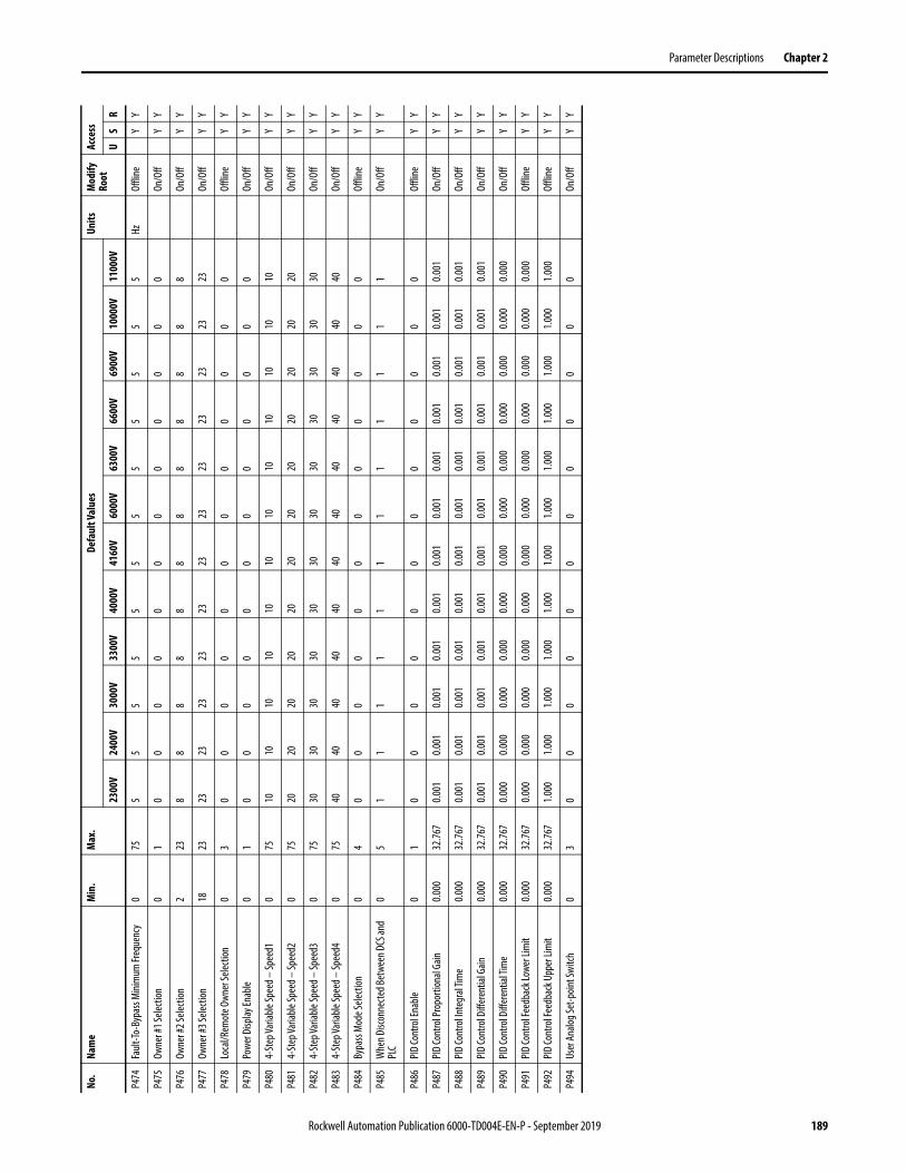
Parameter Descriptions Chapter 2
P474
Fault
-To-B
ypas
s Mini
mum
Freq
uenc
y0
755
55
55
55
55
55
5Hz
Offli
neY
Y
P475
Owne
r #1 S
electi
on0
10
00
00
00
00
00
0On
/Off
YY
P476
Owne
r #2 S
electi
on2
238
88
88
88
88
88
8On
/Off
YY
P477
Owne
r #3 S
electi
on18
2323
2323
2323
2323
2323
2323
23On
/Off
YY
P478
Loca
l/Rem
ote O
wner
Selec
tion
03
00
00
00
00
00
00
Offli
neY
Y
P479
Powe
r Disp
lay En
able
01
00
00
00
00
00
00
On/O
ffY
Y
P480
4-St
ep Va
riable
Spee
d – Sp
eed1
075
1010
1010
1010
1010
1010
1010
On/O
ffY
Y
P481
4-St
ep Va
riable
Spee
d – Sp
eed2
075
2020
2020
2020
2020
2020
2020
On/O
ffY
Y
P482
4-St
ep Va
riable
Spee
d – Sp
eed3
075
3030
3030
3030
3030
3030
3030
On/O
ffY
Y
P483
4-St
ep Va
riable
Spee
d – Sp
eed4
075
4040
4040
4040
4040
4040
4040
On/O
ffY
Y
P484
Bypa
ss M
ode S
electi
on0
40
00
00
00
00
00
0Of
fline
YY
P485
Whe
n Disc
onne
cted B
etwe
en D
CS an
d PL
C0
51
11
11
11
11
11
1On
/Off
YY
P486
PID
Cont
rol E
nable
01
00
00
00
00
00
00
Offli
neY
Y
P487
PID
Cont
rol P
ropo
rtion
al Ga
in0.0
0032
.767
0.001
0.001
0.001
0.001
0.001
0.001
0.001
0.001
0.001
0.001
0.001
0.001
On/O
ffY
Y
P488
PID
Cont
rol In
tegr
al Tim
e0.0
0032
.767
0.001
0.001
0.001
0.001
0.001
0.001
0.001
0.001
0.001
0.001
0.001
0.001
On/O
ffY
Y
P489
PID
Cont
rol D
iffer
entia
l Gain
0.000
32.76
70.0
010.0
010.0
010.0
010.0
010.0
010.0
010.0
010.0
010.0
010.0
010.0
01On
/Off
YY
P490
PID
Cont
rol D
iffer
entia
l Tim
e0.0
0032
.767
0.000
0.000
0.000
0.000
0.000
0.000
0.000
0.000
0.000
0.000
0.000
0.000
On/O
ffY
Y
P491
PID
Cont
rol F
eedb
ack L
ower
Lim
it0.0
0032
.767
0.000
0.000
0.000
0.000
0.000
0.000
0.000
0.000
0.000
0.000
0.000
0.000
Offli
neY
Y
P492
PID
Cont
rol F
eedb
ack U
pper
Lim
it0.0
0032
.767
1.000
1.000
1.000
1.000
1.000
1.000
1.000
1.000
1.000
1.000
1.000
1.000
Offli
neY
Y
P494
User
Ana
log Se
t-poin
t Swi
tch0
30
00
00
00
00
00
0On
/Off
YY
No.
Nam
eM
in.
Max
.De
faul
t Val
ues
Units
Mod
ify
Root
Acce
ss
2300
V24
00V
3000
V33
00V
4000
V41
60V
6000
V63
00V
6600
V69
00V
1000
0V11
000V
US
R
Rockwell Automation Publication 6000-TD004E-EN-P - September 2019 189
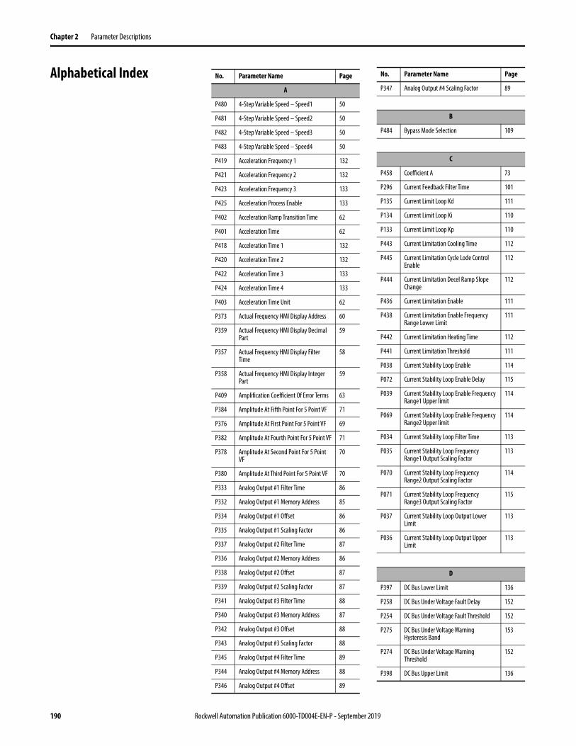
Chapter 2 Parameter Descriptions
Alphabetical Index No. Parameter Name Page
A
P480 4-Step Variable Speed – Speed1 50
P481 4-Step Variable Speed – Speed2 50
P482 4-Step Variable Speed – Speed3 50
P483 4-Step Variable Speed – Speed4 50
P419 Acceleration Frequency 1 132
P421 Acceleration Frequency 2 132
P423 Acceleration Frequency 3 133
P425 Acceleration Process Enable 133
P402 Acceleration Ramp Transition Time 62
P401 Acceleration Time 62
P418 Acceleration Time 1 132
P420 Acceleration Time 2 132
P422 Acceleration Time 3 133
P424 Acceleration Time 4 133
P403 Acceleration Time Unit 62
P373 Actual Frequency HMI Display Address 60
P359 Actual Frequency HMI Display Decimal Part
59
P357 Actual Frequency HMI Display Filter Time
58
P358 Actual Frequency HMI Display Integer Part
59
P409 Amplification Coefficient Of Error Terms 63
P384 Amplitude At Fifth Point For 5 Point VF 71
P376 Amplitude At First Point For 5 Point VF 69
P382 Amplitude At Fourth Point For 5 Point VF 71
P378 Amplitude At Second Point For 5 Point VF
70
P380 Amplitude At Third Point For 5 Point VF 70
P333 Analog Output #1 Filter Time 86
P332 Analog Output #1 Memory Address 85
P334 Analog Output #1 Offset 86
P335 Analog Output #1 Scaling Factor 86
P337 Analog Output #2 Filter Time 87
P336 Analog Output #2 Memory Address 86
P338 Analog Output #2 Offset 87
P339 Analog Output #2 Scaling Factor 87
P341 Analog Output #3 Filter Time 88
P340 Analog Output #3 Memory Address 87
P342 Analog Output #3 Offset 88
P343 Analog Output #3 Scaling Factor 88
P345 Analog Output #4 Filter Time 89
P344 Analog Output #4 Memory Address 88
P346 Analog Output #4 Offset 89
P347 Analog Output #4 Scaling Factor 89
B
P484 Bypass Mode Selection 109
C
P458 Coefficient A 73
P296 Current Feedback Filter Time 101
P135 Current Limit Loop Kd 111
P134 Current Limit Loop Ki 110
P133 Current Limit Loop Kp 110
P443 Current Limitation Cooling Time 112
P445 Current Limitation Cycle Lode Control Enable
112
P444 Current Limitation Decel Ramp Slope Change
112
P436 Current Limitation Enable 111
P438 Current Limitation Enable Frequency Range Lower Limit
111
P442 Current Limitation Heating Time 112
P441 Current Limitation Threshold 111
P038 Current Stability Loop Enable 114
P072 Current Stability Loop Enable Delay 115
P039 Current Stability Loop Enable Frequency Range1 Upper limit
114
P069 Current Stability Loop Enable Frequency Range2 Upper limit
114
P034 Current Stability Loop Filter Time 113
P035 Current Stability Loop Frequency Range1 Output Scaling Factor
113
P070 Current Stability Loop Frequency Range2 Output Scaling Factor
114
P071 Current Stability Loop Frequency Range3 Output Scaling Factor
115
P037 Current Stability Loop Output Lower Limit
113
P036 Current Stability Loop Output Upper Limit
113
D
P397 DC Bus Lower Limit 136
P258 DC Bus Under Voltage Fault Delay 152
P254 DC Bus Under Voltage Fault Threshold 152
P275 DC Bus Under Voltage Warning Hysteresis Band
153
P274 DC Bus Under Voltage Warning Threshold
152
P398 DC Bus Upper Limit 136
No. Parameter Name Page
190 Rockwell Automation Publication 6000-TD004E-EN-P - September 2019

Parameter Descriptions Chapter 2
P267 DC Bus Voltage Deviation Fault Filter Time
152
P266 DC Bus Voltage Deviation Fault Threshold
152
P277 DC Link Voltage Sag Scaling At Rated Load
56
P396 Deceleration Control Enable 135
P435 Deceleration Control Frequency Range 136
P387 Deceleration Frequency 1 130
P389 Deceleration Frequency 2 131
P391 Deceleration Frequency 3 131
P434 Deceleration Iq Threshold 136
P385 Deceleration Process Enable 130
P405 Deceleration Ramp Transition Time 62
P399 Deceleration Time 61
P386 Deceleration Time 1 130
P388 Deceleration Time 2 130
P390 Deceleration Time 3 131
P392 Deceleration Time 4 131
P406 Deceleration Time Unit 63
P270 Delayed Lockout Time of Stop Operation 66
P278 Derating Control Enable Threshold 100
P279 Derating Control Output Filter Time 100
P182 Derating Function Enable 97
P302 Digital Output #0 Bit Selection 78
P303 Digital Output #0 Delay 78
P301 Digital Output #0 Logic 78
P300 Digital Output #0 Memory Address 77
P306 Digital Output #1 Bit Selection 79
P307 Digital Output #1 Delay 79
P305 Digital Output #1 Logic 79
P304 Digital Output #1 Memory Address 78
P310 Digital Output #2 Bit Selection 80
P311 Digital Output #2 Delay 80
P309 Digital Output #2 Logic 80
P308 Digital Output #2 Memory Address 79
P314 Digital Output #3 Bit Selection 81
P315 Digital Output #3 Delay 81
P313 Digital Output #3 Logic 81
P312 Digital Output #3 Memory Address 80
P318 Digital Output #4 Bit Selection 82
P319 Digital Output #4 Delay 82
P317 Digital Output #4 Logic 82
P316 Digital Output #4 Memory Address 81
No. Parameter Name Page
P322 Digital Output #5 Bit Selection 83
P323 Digital Output #5 Delay 83
P321 Digital Output #5 Logic 83
P320 Digital Output #5 Memory Address 82
P326 Digital Output #6 Bit Selection 84
P327 Digital Output #6 Delay 84
P325 Digital Output #6 Logic 84
P324 Digital Output #6 Memory Address 83
P330 Digital Output #7 Bit Selection 85
P331 Digital Output #7 Delay 85
P329 Digital Output #7 Logic 85
P328 Digital Output #7 Memory Address 84
P185 Drive Output Current Upper Limitation Per Cooling Fan Input Voltage Drop
98
P186 Drive Start Delay 93
E
P019 Encoder Resolution 53
F
P101 Fan Control Fan Feedback Delay 91
P102 Fan Control Fan Stop Delay 92
P117 Fan Control Filter Cabinet Fan Fault Trip Delay
92
P095 Fan Control Group #1 Fan Number 90
P096 Fan Control Group #2 Fan Number 90
P097 Fan Control Group #3 Fan Number 90
P098 Fan Control Group #4 Fan Number 91
P099 Fan Control Main Cooling Fan Cycle Time 91
P094 Fan Control Mode 90
P100 Fan Control Redundant Fan Working Time
91
P106 Fan Control Transformer Cabinet Fan Quantity Upper Limit
92
P116 Fan Control TX Cabinet Fan Fault Trip Delay
92
P462 Fault Reset Timeout 127
P473 Fault-To-Bypass Delay When Starting Motor
110
P472 Fault-To-Bypass Delay 109
P474 Fault-To-Bypass Minimum Frequency, Zero through Rated Frequency
110
P471 Fault-To-Bypass 109
P298 Filter Time A For DC Bus Average Value 101
P299 Filter Time B For DC Bus Average Value 101
P211 Filter Time For Abnormal Output Voltage 144
No. Parameter Name Page
Rockwell Automation Publication 6000-TD004E-EN-P - September 2019 191

Chapter 2 Parameter Descriptions
P228 Filter Time For Ground Fault 147
P221 Filter Time For Output Over Voltage 146
P212 Filter Time For Output Short-Circuit 144
P232 Filter Time For Overspeed Fault (Lower Limit)
148
P231 Filter Time For Overspeed Fault (Upper Limit)
148
P272 Flux Control Compensation Gain 99
P273 Flux Control Regulation Control Enable 99
P268 Flux Control Signal Filter Time 99
P276 Flux Control-Lag Band Width 100
P271 Flux Delay 68
P454 Flux Time 72
P394 Flying Start Compensation Current Threshold
116
P410 Flying Start Compensation Current Threshold for Fast Compensation
117
P408 Flying Start Compensation Defer Restore Voltage Speed Current Threshold
117
P393 Flying Start Compensation Enable 116
P395 Flying Start Compensation Frequency Reduce Speed
117
P463 Flying Start Low/High Speed Regions Boundary
118
P416 Flying Start Mode 117
P417 Flying Start Motor Speed Search Timeout
118
P459 Flying Start Voltage Recovery Time (High Speed Region)
118
P457 Flying Start Voltage Recovery Time (Low Speed Region)
118
P187 Flying Start Voltage Threshold 116
P114 Flying Start-Current Comparison Delay For Motor Speed Search
115
P115 Flying Start-Current Threshold For Successful Motor Speed Search
116
P113 Flying Start-Initial Output Voltage 115
P383 Frequency At Fifth Point For 5 Point VF 71
P375 Frequency At First Point For 5 Point VF 69
P381 Frequency At Fourth Point For 5 Point VF 71
P377 Frequency At Second Point For 5 Point VF
70
P379 Frequency At Third Point For 5 Point VF 70
P414 Frequency Command Deadband Upper Limit
63
P413 Frequency Command Lower Limit 63
P415 Frequency Command Upper Limit 64
P251 Frequency Command-Low Frequency Region Boundary
65
No. Parameter Name Page
P235 Frequency Deviation Warning Cancellation Threshold
149
P237 Frequency Deviation Warning Delay 150
P236 Frequency Deviation Warning Threshold 149
G
P227 Ground Fault Detection Scaling Correction Factor
147
P230 Ground Fault Trip Threshold 148
P256 Ground Fault Warning Cancellation Threshold
151
P229 Ground Fault Warning Threshold 148
H
P110 Heating Current Threshold 138
I
P200 Ia Motor Current Memory Address 75
P202 Ic Motor Current Memory Address 76
P250 Input Contactor/Circuit Breaker Close Delay
56
P073 Input Voltage Loss Filter Time 104
P295 Iq Filter Time For Slip Estimation 69
L
P195 Line CT Ratio 55
P196 Line CT Burden Resistor 55
P168 Line Current Filter Time 142
P177 Line Current Negative Sequence Fault Delay
143
P176 Line Current Negative Sequence Fault Threshold
143
P175 Line Current Negative Sequence Filter Time
143
P171 Line Current Phase A Scaling Factor 75
P172 Line Current Phase B Scaling Factor 75
P173 Line Current Phase C Scaling Factor 75
P174 Line Current Positive Sequence Filter Time
142
P161 Line Neutral Over Voltage Fault Delay 140
P160 Line Neutral Over Voltage Fault Threshold
140
P159 Line Neutral Over Voltage Warning Delay
140
P158 Line Neutral Over Voltage Warning Threshold
139
P155 Line Over Voltage Fault Delay 139
P154 Line Over Voltage Fault Threshold 138
No. Parameter Name Page
192 Rockwell Automation Publication 6000-TD004E-EN-P - September 2019

Parameter Descriptions Chapter 2
P147 Line Rated Frequency 54
P146 Line Rated Voltage 54
P170 Line Short Circuit Fault Delay 142
P169 Line Short Circuit Fault Threshold 142
P157 Line Under Voltage Warning Delay 139
P156 Line Under Voltage Warning Threshold 139
P165 Line Voltage Negative Sequence Fault Delay
141
P164 Line Voltage Negative Sequence Fault Threshold
141
P163 Line Voltage Negative Sequence Filter Time
141
P166 Line Voltage Phaser Sequence Reverse Enable
141
P162 Line Voltage Positive Sequence Filter Time
140
P151 Line Voltage Uab Scaling Factor 74
P152 Line Voltage Ubc Scaling Factor 74
P153 Line Voltage Ung Scaling Factor 74
P047 Load Loss Control Differential Scaling 119
P045 Load Loss Control Enable 119
P053 Load Loss Control Exit Delay 121
P051 Load Loss Control Filter Time 120
P050 Load Loss Control Integral Time 120
P049 Load Loss Control Scaling Factor 120
P052 Load Loss Enable Current Threshold 120
P046 Load Loss Enable Frequency 119
P048 Load Loss Frequency Compensation Upper Limit
119
P478 Local/Remote Control Owner Selection 49
P451 Low Speed Voltage Compensation 72
P449 Low Speed Voltage Compensation During Flux Building Process
129
P452 Low Speed Voltage Compensation Frequency Threshold
72
P283 Low Voltage Ride Through Enable 102
P285 Low Voltage Ride Through Max Time Limit
103
P281 Low Voltage Ride Through Min Time Interval
102
P284 Low Voltage Ride Through Min Time Limit
103
P282 Low Voltage Ride Through Min Frequency Limit
102
P289 Low Voltage Ride Through Motor Speed Estimation Filter Time
104
P286 Low Voltage Ride Through Recovery Frequency Compensation Factor
103
P287 Low Voltage Ride Through Recovery Time
103
No. Parameter Name Page
P280 Low Voltage Ride Through Recovery Voltage Boost Coefficient
102
P288 Low Voltage Ride Through System Delay Correction Factor
104
M
P466 Maximum Output Frequency 64
P448 Minimum Start Frequency 129
P447 Minimum Start Frequency During Time 129
P455 Modulation Index 73
P125 Motor Autotune Current Id Ki 122
P124 Motor Autotune Current Id Kp 122
P127 Motor Autotune Current Iq Ki 123
P126 Motor Autotune Current Iq Kp 122
P122 Motor Autotune Delay 121
P123 Motor Autotune Filter Time 122
P128 Motor Autotune Id Feedback Error Valid 123
P130 Motor Autotune Id Reference 123
P131 Motor Autotune Iq Reference 124
P129 Motor Autotune Lr/Lm 123
P179 Motor Autotune Maximum Iq For No Load
126
P178 Motor Autotune Rs Upper Limit 126
P136 Motor Autotune Rs/Rr 124
P121 Motor Autotune Selection 121
P132 Motor Autotune Time Limit 124
P253 Motor Coast Stop Time 65
P374 Motor Current HMI Display Address 61
P362 Motor Current HMI Display Decimal Part 60
P360 Motor Current HMI Display Filter Time 59
P361 Motor Current HMI Display Integer Part 59
P198 Motor HECS Burden Resistor 55
P197 Motor HECS Ratio 55
P201 Motor Ia Scaling Factor 76
P203 Motor Ic Scaling Factor 76
P252 Motor In Stopping Condition Threshold 65
P139 Motor Magnetizing Current Id 125
P141 Motor Magnetizing Inductance Lm 125
P214 Motor Minimum Overload Current 145
P108 Motor Overload Current Offset 138
P215 Motor Overload Cycle Time 145
P217 Motor Overload Time 146
P137 Motor Rated Current 124
P199 Motor Rated Current 56
No. Parameter Name Page
Rockwell Automation Publication 6000-TD004E-EN-P - September 2019 193

Chapter 2 Parameter Descriptions
P013 Motor Rated Power 52
P015 Motor Rated Power Factor 53
P014 Motor Rated Speed 52
P012 Motor Rated Voltage 52
P009 Motor Rotation Direction Command Selection
66
P008 Motor Rotation Direction Under Local Control
66
P143 Motor Rotor Leakage Inductance Llr 126
P140 Motor Rotor Resistance Rr 125
P239 Motor Stall Fault Delay 150
P238 Motor Stall Fault Threshold 150
P257 Motor Stall Warning Cancellation Threshold
151
P142 Motor Stator Leakage Inductance LIs 126
P138 Motor Stator Resistance Rs 125
P204 Motor Uab Voltage Address 76
P205 Motor Uab Voltage Scaling Factor 77
P206 Motor Uac Voltage Scaling Factor 77
P372 Motor Voltage HMI Display Address 60
P356 Motor Voltage HMI Display Decimal Part 58
P354 Motor Voltage HMI Display Filter Time 58
P355 Motor Voltage HMI Display Integer Part 58
P456 Motor Voltage Upper Limit 73
P216 Motor Overload Trip Threshold 145
N
P017 Number of Motor Pole Pairs 53
P007 Number of Power Cells Per Phase 51
O
P068 One Phase Lost Filter Time 108
P222 Output Over Voltage Fault Threshold 146
P213 Output Short-Circuit Fault Threshold 145
P226 Output Voltage Abnormality Warning Cancellation Threshold
147
P224 Output Voltage Deviation Fault Threshold
147
P223 Output Voltage Deviation Warning Threshold
146
P467 Over Speed Enable 64
P412 Over Speed Lower Limit Reference 153
P411 Over Speed Upper Limit Reference 153
P475 Owner #1 Selection 48
P476 Owner #2 Selection 48
P477 Owner #3 Selection 49
No. Parameter Name Page
P
P208 Phase Over Current Enable Frequency Range Upper limit
143
P209 Phase Over Current Filter Time 144
P210 Phase Over Current Threshold 144
P489 PID Control Differential Gain 134
P490 PID Control Differential Time 135
P486 PID Control Enable 134
P491 PID Control Feedback Lower Limit 135
P492 PID Control Feedback Upper Limit 135
P488 PID Control Integral Time 134
P487 PID Control Proportional Gain 134
P042 Power Cell Bypass Delay After Power Cell Bypassed
105
P041 Power Cell Bypass Enable 105
P065 Power Cell Bypass Enable Frequency Range Lower limit
107
P061 Power Cell Bypass Fault Simulation 107
P044 Power Cell Bypass Fault Simulation Power Cell Count
106
P058 Power Cell Bypass Phase A Cell Number For Simulation
106
P059 Power Cell Bypass Phase B Cell Number For Simulation
107
P060 Power Cell Bypass Phase C Cell Number For Simulation
107
P066 Power Cell Bypass Restart Enable After Power Cell Bypassed
108
P043 Power Cell Bypass Upper Limit For Bypassed Feedback Time
106
P057 Power Cell Bypass Upper Limit Time For Over Temperature
106
P011 Power Cell DC Bus Rated Voltage 52
P465 Power Cell Fault Auto Reset Delay 127
P078 Power Cell Reactivation Time Upper Limit
108
P479 Power Display Enable 61
P264 Power Loss Allowable Time 105
P263 Power Loss Restart Enable 104
P265 Power Loss Time Max Limit 105
P030 Powercell Fault Trip Signal Mask Register 95
P105 Pre-charge DC Bus Threshold 94
P103 Pre-charge Enable 93
P104 Pre-charge Feedback Delay 93
P118 Pre-charge Max Time 94
P119 Pre-charge Min Repeat Interval 94
P120 Pre-charge Primary Voltage Threshold 94
No. Parameter Name Page
194 Rockwell Automation Publication 6000-TD004E-EN-P - September 2019

Parameter Descriptions Chapter 2
P181 Pre-charge Resistor Short Circuit Fault Delay
95
P180 Pre-charge Resistor Short Circuit Fault Threshold
95
R
P371 Rated Frequency HMI Display Address 60
P353 Rated Frequency HMI Display Decimal Part
57
P351 Rated Frequency HMI Display Filter Time 57
P352 Rated Frequency HMI Display Integer Part
57
P460 Rated Output Frequency 64
P461 Restart Enable 127
S
P040 Safe Start Condition 56
P090 Skip Frequency 1 Lower Limit 128
P091 Skip Frequency 1 Upper Limit 128
P092 Skip Frequency 2 Lower Limit 128
P093 Skip Frequency 2 Upper Limit 129
P089 Skip Frequency Enable 128
P111 Slip Compensation Enable 67
P024 Stop Method 65
P293 SVC Flux Voltage Boost Coefficient 68
P294 SVC Flux Voltage Boost Upper Frequency 69
P292 SVC Low Frequency Acceleration Time 68
P291 SVC Low Frequency Acceleration Time Enable Frequency Range Upper Limit
68
P088 Switch Frequency Setting 67
P087 Switch Frequency Setting Enable Code 67
P269 System Derating Control Signal Filter Time
99
P145 System Fault B Trip Signal Mask 96
P031 System Fault Trip Signal Mask 96
T
P233 Threshold Of Over-Speed Fault At Lower Frequency Limit
149
P234 Threshold Of Over-Speed Fault At Upper Frequency Limit
149
P240 Transformer Over Temperature Fault Delay
150
P241 Transformer Over Temperature Warning Delay
151
P148 Transformer Rated Power 54
P149 Transformer Short Circuit Impedance 54
No. Parameter Name Page
U
P494 User Analog Set-point Switch 57
V
P453 V/F Curve 72
P470 Version Compatibility Enable 89
P079 VFD Minimum Overload Current 137
P107 VFD Overload Current Offset 138
P082 VFD Overload Cycle Time 137
P081 VFD Overload Time 137
P085 VFD Rated Current 53
P080 VFD Overload Current 137
P297 Voltage Feedback Filter Time 101
P290 Voltage Loop Enable 100
P183 Voltage Lower Threshold For Drive Derating Per Cooling Fan Input Voltage Drop
98
P184 Voltage Upper Threshold For Drive Derating Per Cooling Fan Input Voltage Drop
98
W
P485 When Disconnected Between DCS and PLC
51
No. Parameter Name Page
Rockwell Automation Publication 6000-TD004E-EN-P - September 2019 195

Chapter 2 Parameter Descriptions
Linear Number Index No. Parameter Name Page
P007 Number of Power Cells Per Phase 51
P008 Motor Rotation Direction Under Local Control
66
P009 Motor Rotation Direction Command Selection
66
P011 Power Cell DC Bus Rated Voltage 52
P012 Motor Rated Voltage 52
P013 Motor Rated Power 52
P014 Motor Rated Speed 52
P015 Motor Rated Power Factor 53
P017 Number of Motor Pole Pairs 53
P019 Encoder Resolution 53
P024 Stop Method 65
P030 Powercell Fault Trip Signal Mask 95
P031 System Fault Trip Signal Mask 96
P034 Current Stability Loop Filter Time 113
P035 Current Stability Loop Frequency Range1 Output Scaling Factor
113
P036 Current Stability Loop Output Upper Limit
113
P037 Current Stability Loop Output Lower Limit
113
P038 Current Stability Loop Enable 114
P039 Current Stability Loop Enable Frequency Range1 Upper limit
114
P040 Safe Start Condition 56
P041 Power Cell Bypass Enable 105
P042 Power Cell Bypass Delay After Power Cell Bypassed
105
P043 Power Cell Bypass Upper Limit For Bypassed Feedback Time
106
P044 Power Cell Bypass Fault Simulation Power Cell Count
106
P045 Load Loss Control Enable 119
P046 Load Loss Enable Frequency 119
P047 Load Loss Control Differential Scaling 119
P048 Load Loss Frequency Compensation Upper Limit
119
P049 Load Loss Control Scaling Factor 120
P050 Load Loss Control Integral Time 120
P051 Load Loss Control Filter Time 120
P052 Load Loss Enable Current Threshold 120
P053 Load Loss Control Exit Delay 121
P057 Power Cell Bypass Upper Limit Time For Over Temperature
106
P058 Power Cell Bypass Phase A Cell Number For Simulation
106
P059 Power Cell Bypass Phase B Cell Number For Simulation
107
P060 Power Cell Bypass Phase C Cell Number For Simulation
107
P061 Power Cell Bypass Fault Simulation 107
P065 Power Cell Bypass Enable Frequency Range Lower limit
107
P066 Power Cell Bypass Restart Enable After Power Cell Bypassed
108
P068 One Phase Lost Filter Time 108
P069 Current Stability Loop Enable Frequency Range2 Upper Limit
114
P070 Current Stability Loop Frequency Range2 Output Scaling Factor
114
P071 Current Stability Loop Frequency Range3 Output Scaling Factor
115
P072 Current Stability Loop Enable Delay 115
P073 Input Voltage Loss Filter Time 104
P078 Power Cell Reactivation Time Upper Limit
108
P079 VFD Minimum Overload Current 137
P080 VFD Overload Current 137
P081 VFD Overload Time 137
P082 VFD Overload Cycle Time 137
P085 VFD Rated Current 53
P087 Switch Frequency Setting Enable Code 67
P088 Switch Frequency Setting 67
P089 Skip Frequency Enable 128
P090 Skip Frequency 1 Lower Limit 128
P091 Skip Frequency 1 Upper Limit 128
P092 Skip Frequency 2 Lower Limit 128
P093 Skip Frequency 2 Upper Limit 129
P094 Fan Control Mode 90
P095 Fan Control Group #1 Fan Number 90
P096 Fan Control Group #2 Fan Number 90
P097 Fan Control Group #3 Fan Number 90
P098 Fan Control Group #4 Fan Number 91
P099 Fan Control Main Cooling Fan Cycle Time 91
P100 Fan Control Redundant Fan Working Time
91
P101 Fan Control Fan Feedback Delay 91
P102 Fan Control Fan Stop Delay 92
P103 Pre-charge Enable 93
P104 Pre-charge Feedback Delay 93
P105 Pre-charge DC Bus Threshold 94
P106 Fan Control Transformer Cabinet Fan Quantity Upper Limit
92
P107 VFD Overload Current Offset 138
P108 Motor Overload Current Offset 138
No. Parameter Name Page
196 Rockwell Automation Publication 6000-TD004E-EN-P - September 2019
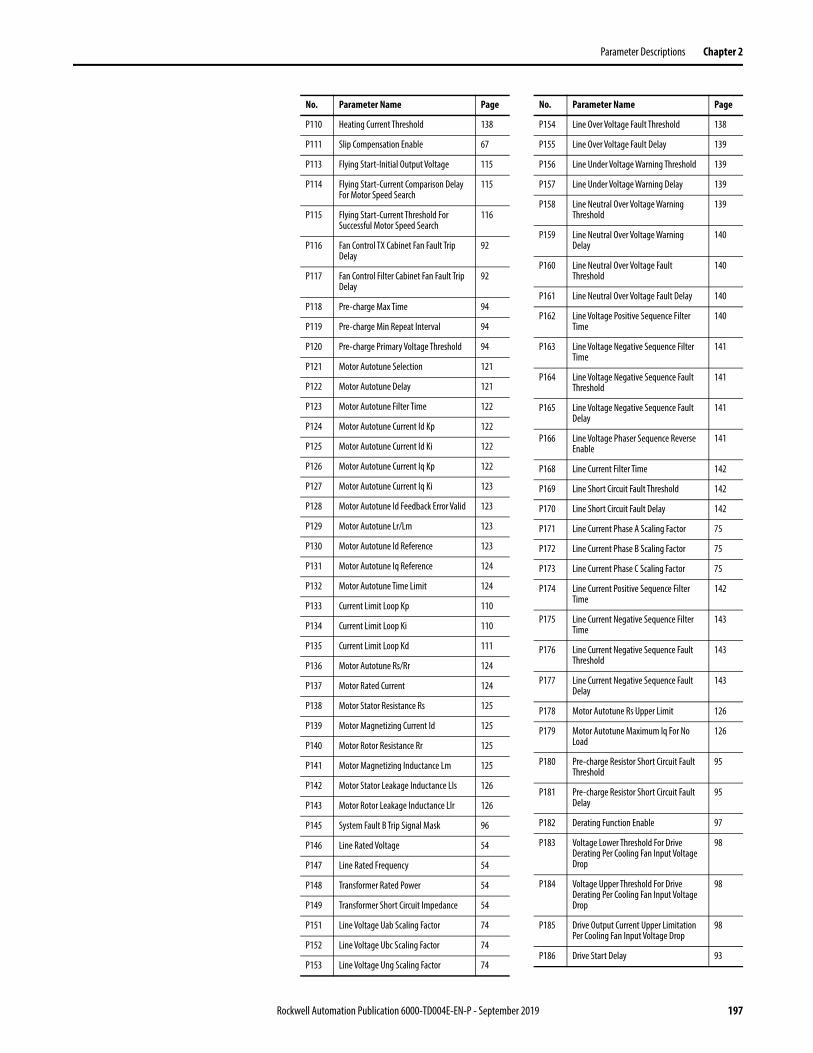
Parameter Descriptions Chapter 2
P110 Heating Current Threshold 138
P111 Slip Compensation Enable 67
P113 Flying Start-Initial Output Voltage 115
P114 Flying Start-Current Comparison Delay For Motor Speed Search
115
P115 Flying Start-Current Threshold For Successful Motor Speed Search
116
P116 Fan Control TX Cabinet Fan Fault Trip Delay
92
P117 Fan Control Filter Cabinet Fan Fault Trip Delay
92
P118 Pre-charge Max Time 94
P119 Pre-charge Min Repeat Interval 94
P120 Pre-charge Primary Voltage Threshold 94
P121 Motor Autotune Selection 121
P122 Motor Autotune Delay 121
P123 Motor Autotune Filter Time 122
P124 Motor Autotune Current Id Kp 122
P125 Motor Autotune Current Id Ki 122
P126 Motor Autotune Current Iq Kp 122
P127 Motor Autotune Current Iq Ki 123
P128 Motor Autotune Id Feedback Error Valid 123
P129 Motor Autotune Lr/Lm 123
P130 Motor Autotune Id Reference 123
P131 Motor Autotune Iq Reference 124
P132 Motor Autotune Time Limit 124
P133 Current Limit Loop Kp 110
P134 Current Limit Loop Ki 110
P135 Current Limit Loop Kd 111
P136 Motor Autotune Rs/Rr 124
P137 Motor Rated Current 124
P138 Motor Stator Resistance Rs 125
P139 Motor Magnetizing Current Id 125
P140 Motor Rotor Resistance Rr 125
P141 Motor Magnetizing Inductance Lm 125
P142 Motor Stator Leakage Inductance LIs 126
P143 Motor Rotor Leakage Inductance Llr 126
P145 System Fault B Trip Signal Mask 96
P146 Line Rated Voltage 54
P147 Line Rated Frequency 54
P148 Transformer Rated Power 54
P149 Transformer Short Circuit Impedance 54
P151 Line Voltage Uab Scaling Factor 74
P152 Line Voltage Ubc Scaling Factor 74
P153 Line Voltage Ung Scaling Factor 74
No. Parameter Name Page
P154 Line Over Voltage Fault Threshold 138
P155 Line Over Voltage Fault Delay 139
P156 Line Under Voltage Warning Threshold 139
P157 Line Under Voltage Warning Delay 139
P158 Line Neutral Over Voltage Warning Threshold
139
P159 Line Neutral Over Voltage Warning Delay
140
P160 Line Neutral Over Voltage Fault Threshold
140
P161 Line Neutral Over Voltage Fault Delay 140
P162 Line Voltage Positive Sequence Filter Time
140
P163 Line Voltage Negative Sequence Filter Time
141
P164 Line Voltage Negative Sequence Fault Threshold
141
P165 Line Voltage Negative Sequence Fault Delay
141
P166 Line Voltage Phaser Sequence Reverse Enable
141
P168 Line Current Filter Time 142
P169 Line Short Circuit Fault Threshold 142
P170 Line Short Circuit Fault Delay 142
P171 Line Current Phase A Scaling Factor 75
P172 Line Current Phase B Scaling Factor 75
P173 Line Current Phase C Scaling Factor 75
P174 Line Current Positive Sequence Filter Time
142
P175 Line Current Negative Sequence Filter Time
143
P176 Line Current Negative Sequence Fault Threshold
143
P177 Line Current Negative Sequence Fault Delay
143
P178 Motor Autotune Rs Upper Limit 126
P179 Motor Autotune Maximum Iq For No Load
126
P180 Pre-charge Resistor Short Circuit Fault Threshold
95
P181 Pre-charge Resistor Short Circuit Fault Delay
95
P182 Derating Function Enable 97
P183 Voltage Lower Threshold For Drive Derating Per Cooling Fan Input Voltage Drop
98
P184 Voltage Upper Threshold For Drive Derating Per Cooling Fan Input Voltage Drop
98
P185 Drive Output Current Upper Limitation Per Cooling Fan Input Voltage Drop
98
P186 Drive Start Delay 93
No. Parameter Name Page
Rockwell Automation Publication 6000-TD004E-EN-P - September 2019 197
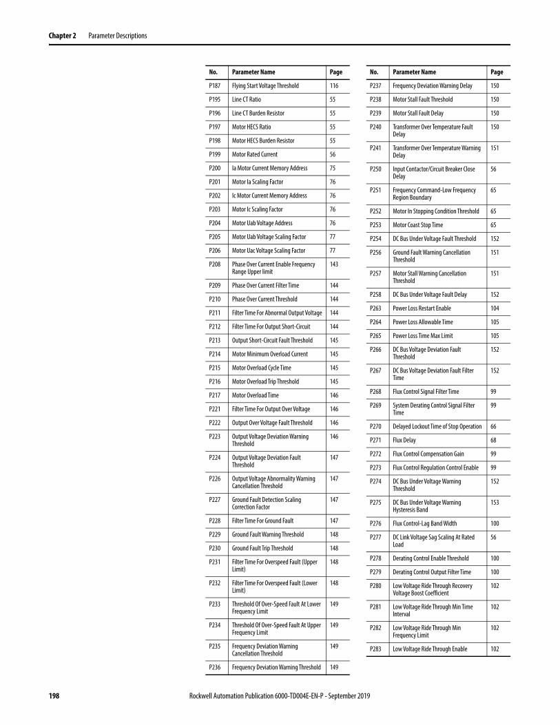
Chapter 2 Parameter Descriptions
P187 Flying Start Voltage Threshold 116
P195 Line CT Ratio 55
P196 Line CT Burden Resistor 55
P197 Motor HECS Ratio 55
P198 Motor HECS Burden Resistor 55
P199 Motor Rated Current 56
P200 Ia Motor Current Memory Address 75
P201 Motor Ia Scaling Factor 76
P202 Ic Motor Current Memory Address 76
P203 Motor Ic Scaling Factor 76
P204 Motor Uab Voltage Address 76
P205 Motor Uab Voltage Scaling Factor 77
P206 Motor Uac Voltage Scaling Factor 77
P208 Phase Over Current Enable Frequency Range Upper limit
143
P209 Phase Over Current Filter Time 144
P210 Phase Over Current Threshold 144
P211 Filter Time For Abnormal Output Voltage 144
P212 Filter Time For Output Short-Circuit 144
P213 Output Short-Circuit Fault Threshold 145
P214 Motor Minimum Overload Current 145
P215 Motor Overload Cycle Time 145
P216 Motor Overload Trip Threshold 145
P217 Motor Overload Time 146
P221 Filter Time For Output Over Voltage 146
P222 Output Over Voltage Fault Threshold 146
P223 Output Voltage Deviation Warning Threshold
146
P224 Output Voltage Deviation Fault Threshold
147
P226 Output Voltage Abnormality Warning Cancellation Threshold
147
P227 Ground Fault Detection Scaling Correction Factor
147
P228 Filter Time For Ground Fault 147
P229 Ground Fault Warning Threshold 148
P230 Ground Fault Trip Threshold 148
P231 Filter Time For Overspeed Fault (Upper Limit)
148
P232 Filter Time For Overspeed Fault (Lower Limit)
148
P233 Threshold Of Over-Speed Fault At Lower Frequency Limit
149
P234 Threshold Of Over-Speed Fault At Upper Frequency Limit
149
P235 Frequency Deviation Warning Cancellation Threshold
149
P236 Frequency Deviation Warning Threshold 149
No. Parameter Name Page
P237 Frequency Deviation Warning Delay 150
P238 Motor Stall Fault Threshold 150
P239 Motor Stall Fault Delay 150
P240 Transformer Over Temperature Fault Delay
150
P241 Transformer Over Temperature Warning Delay
151
P250 Input Contactor/Circuit Breaker Close Delay
56
P251 Frequency Command-Low Frequency Region Boundary
65
P252 Motor In Stopping Condition Threshold 65
P253 Motor Coast Stop Time 65
P254 DC Bus Under Voltage Fault Threshold 152
P256 Ground Fault Warning Cancellation Threshold
151
P257 Motor Stall Warning Cancellation Threshold
151
P258 DC Bus Under Voltage Fault Delay 152
P263 Power Loss Restart Enable 104
P264 Power Loss Allowable Time 105
P265 Power Loss Time Max Limit 105
P266 DC Bus Voltage Deviation Fault Threshold
152
P267 DC Bus Voltage Deviation Fault Filter Time
152
P268 Flux Control Signal Filter Time 99
P269 System Derating Control Signal Filter Time
99
P270 Delayed Lockout Time of Stop Operation 66
P271 Flux Delay 68
P272 Flux Control Compensation Gain 99
P273 Flux Control Regulation Control Enable 99
P274 DC Bus Under Voltage Warning Threshold
152
P275 DC Bus Under Voltage Warning Hysteresis Band
153
P276 Flux Control-Lag Band Width 100
P277 DC Link Voltage Sag Scaling At Rated Load
56
P278 Derating Control Enable Threshold 100
P279 Derating Control Output Filter Time 100
P280 Low Voltage Ride Through Recovery Voltage Boost Coefficient
102
P281 Low Voltage Ride Through Min Time Interval
102
P282 Low Voltage Ride Through Min Frequency Limit
102
P283 Low Voltage Ride Through Enable 102
No. Parameter Name Page
198 Rockwell Automation Publication 6000-TD004E-EN-P - September 2019

Parameter Descriptions Chapter 2
P284 Low Voltage Ride Through Min Time Limit
103
P285 Low Voltage Ride Through Max Time Limit
103
P286 Low Voltage Ride Through Recovery Frequency Compensation Factor
103
P287 Low Voltage Ride Through Recovery Time
103
P288 Low Voltage Ride Through System Delay Correction Factor
104
P289 Low Voltage Ride Through Motor Speed Estimation Filter Time
104
P290 Voltage Loop Enable 100
P291 SVC Low Frequency Acceleration Time Enable Frequency Range Upper Limit
68
P292 SVC Low Frequency Acceleration Time 68
P293 SVC Flux Voltage Boost Coefficient 68
P294 SVC Flux Voltage Boost Upper Frequency 69
P295 Iq Filter Time For Slip Estimation 69
P296 Current Feedback Filter Time 101
P297 Voltage Feedback Filter Time 101
P298 Filter Time A For DC Bus Average Value 101
P299 Filter Time B For DC Bus Average Value 101
P300 Digital Output #0 Memory Address 77
P301 Digital Output #0 Logic 78
P302 Digital Output #0 Bit Selection 78
P303 Digital Output #0 Delay 78
P304 Digital Output #1 Memory Address 78
P305 Digital Output #1 Logic 79
P306 Digital Output #1 Bit Selection 79
P307 Digital Output #1 Delay 79
P308 Digital Output #2 Memory Address 79
P309 Digital Output #2 Logic 80
P310 Digital Output #2 Bit Selection 80
P311 Digital Output #2 Delay 80
P312 Digital Output #3 Memory Address 80
P313 Digital Output #3 Logic 81
P314 Digital Output #3 Bit Selection 81
P315 Digital Output #3 Delay 81
P316 Digital Output #4 Memory Address 81
P317 Digital Output #4 Logic 82
P318 Digital Output #4 Bit Selection 82
P319 Digital Output #4 Delay 82
P320 Digital Output #5 Memory Address 82
P321 Digital Output #5 Logic 83
P322 Digital Output #5 Bit Selection 83
No. Parameter Name Page
P323 Digital Output #5 Delay 83
P324 Digital Output #6 Memory Address 83
P325 Digital Output #6 Logic 84
P326 Digital Output #6 Bit Selection 84
P327 Digital Output #6 Delay 84
P328 Digital Output #7 Memory Address 84
P329 Digital Output #7 Logic 85
P330 Digital Output #7 Bit Selection 85
P331 Digital Output #7 Delay 85
P332 Analog Output #1 Memory Address 85
P333 Analog Output #1 Filter Time 86
P334 Analog Output #1 Offset 86
P335 Analog Output #1 Scaling Factor 86
P336 Analog Output #2 Memory Address 86
P337 Analog Output #2 Filter Time 87
P338 Analog Output #2 Offset 87
P339 Analog Output #2 Scaling Factor 87
P340 Analog Output #3 Memory Address 87
P341 Analog Output #3 Filter Time 88
P342 Analog Output #3 Offset 88
P343 Analog Output #3 Scaling Factor 88
P344 Analog Output #4 Memory Address 88
P345 Analog Output #4 Filter Time 89
P346 Analog Output #4 Offset 89
P347 Analog Output #4 Scaling Factor 89
P351 Rated Frequency HMI Display Filter Time 57
P352 Rated Frequency HMI Display Integer Part
57
P353 Rated Frequency HMI Display Decimal Part
57
P354 Motor Voltage HMI Display Filter Time 58
P355 Motor Voltage HMI Display Integer Part 58
P356 Motor Voltage HMI Display Decimal Part 58
P357 Actual Frequency HMI Display Filter Time
58
P358 Actual Frequency HMI Display Integer Part
59
P359 Actual Frequency HMI Display Decimal Part
59
P360 Motor Current HMI Display Filter Time 59
P361 Motor Current HMI Display Integer Part 59
P362 Motor Current HMI Display Decimal Part 60
P371 Rated Frequency HMI Display Address 60
P372 Motor Voltage HMI Display Address 60
P373 Actual Frequency HMI Display Address 60
No. Parameter Name Page
Rockwell Automation Publication 6000-TD004E-EN-P - September 2019 199
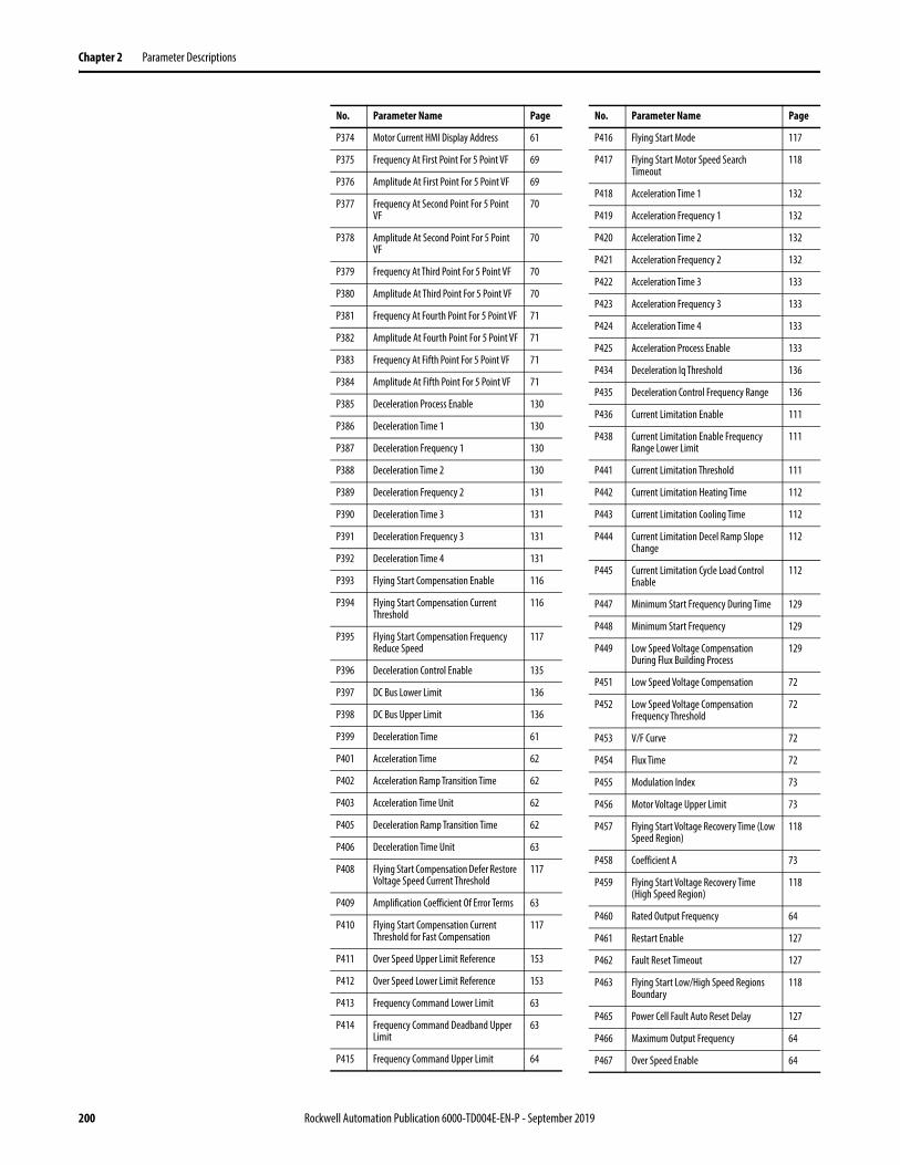
Chapter 2 Parameter Descriptions
P374 Motor Current HMI Display Address 61
P375 Frequency At First Point For 5 Point VF 69
P376 Amplitude At First Point For 5 Point VF 69
P377 Frequency At Second Point For 5 Point VF
70
P378 Amplitude At Second Point For 5 Point VF
70
P379 Frequency At Third Point For 5 Point VF 70
P380 Amplitude At Third Point For 5 Point VF 70
P381 Frequency At Fourth Point For 5 Point VF 71
P382 Amplitude At Fourth Point For 5 Point VF 71
P383 Frequency At Fifth Point For 5 Point VF 71
P384 Amplitude At Fifth Point For 5 Point VF 71
P385 Deceleration Process Enable 130
P386 Deceleration Time 1 130
P387 Deceleration Frequency 1 130
P388 Deceleration Time 2 130
P389 Deceleration Frequency 2 131
P390 Deceleration Time 3 131
P391 Deceleration Frequency 3 131
P392 Deceleration Time 4 131
P393 Flying Start Compensation Enable 116
P394 Flying Start Compensation Current Threshold
116
P395 Flying Start Compensation Frequency Reduce Speed
117
P396 Deceleration Control Enable 135
P397 DC Bus Lower Limit 136
P398 DC Bus Upper Limit 136
P399 Deceleration Time 61
P401 Acceleration Time 62
P402 Acceleration Ramp Transition Time 62
P403 Acceleration Time Unit 62
P405 Deceleration Ramp Transition Time 62
P406 Deceleration Time Unit 63
P408 Flying Start Compensation Defer Restore Voltage Speed Current Threshold
117
P409 Amplification Coefficient Of Error Terms 63
P410 Flying Start Compensation Current Threshold for Fast Compensation
117
P411 Over Speed Upper Limit Reference 153
P412 Over Speed Lower Limit Reference 153
P413 Frequency Command Lower Limit 63
P414 Frequency Command Deadband Upper Limit
63
P415 Frequency Command Upper Limit 64
No. Parameter Name Page
P416 Flying Start Mode 117
P417 Flying Start Motor Speed Search Timeout
118
P418 Acceleration Time 1 132
P419 Acceleration Frequency 1 132
P420 Acceleration Time 2 132
P421 Acceleration Frequency 2 132
P422 Acceleration Time 3 133
P423 Acceleration Frequency 3 133
P424 Acceleration Time 4 133
P425 Acceleration Process Enable 133
P434 Deceleration Iq Threshold 136
P435 Deceleration Control Frequency Range 136
P436 Current Limitation Enable 111
P438 Current Limitation Enable Frequency Range Lower Limit
111
P441 Current Limitation Threshold 111
P442 Current Limitation Heating Time 112
P443 Current Limitation Cooling Time 112
P444 Current Limitation Decel Ramp Slope Change
112
P445 Current Limitation Cycle Load Control Enable
112
P447 Minimum Start Frequency During Time 129
P448 Minimum Start Frequency 129
P449 Low Speed Voltage Compensation During Flux Building Process
129
P451 Low Speed Voltage Compensation 72
P452 Low Speed Voltage Compensation Frequency Threshold
72
P453 V/F Curve 72
P454 Flux Time 72
P455 Modulation Index 73
P456 Motor Voltage Upper Limit 73
P457 Flying Start Voltage Recovery Time (Low Speed Region)
118
P458 Coefficient A 73
P459 Flying Start Voltage Recovery Time (High Speed Region)
118
P460 Rated Output Frequency 64
P461 Restart Enable 127
P462 Fault Reset Timeout 127
P463 Flying Start Low/High Speed Regions Boundary
118
P465 Power Cell Fault Auto Reset Delay 127
P466 Maximum Output Frequency 64
P467 Over Speed Enable 64
No. Parameter Name Page
200 Rockwell Automation Publication 6000-TD004E-EN-P - September 2019
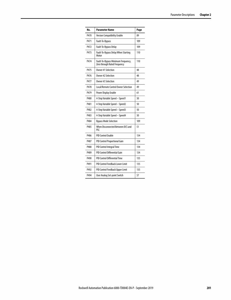
Parameter Descriptions Chapter 2
P470 Version Compatibility Enable 89
P471 Fault-To-Bypass 109
P472 Fault-To-Bypass Delay 109
P473 Fault-To-Bypass Delay When Starting Motor
110
P474 Fault-To-Bypass Minimum Frequency, Zero through Rated Frequency
110
P475 Owner #1 Selection 48
P476 Owner #2 Selection 48
P477 Owner #3 Selection 49
P478 Local/Remote Control Owner Selection 49
P479 Power Display Enable 61
P480 4-Step Variable Speed – Speed1 50
P481 4-Step Variable Speed – Speed2 50
P482 4-Step Variable Speed – Speed3 50
P483 4-Step Variable Speed – Speed4 50
P484 Bypass Mode Selection 109
P485 When Disconnected Between DCS and PLC
51
P486 PID Control Enable 134
P487 PID Control Proportional Gain 134
P488 PID Control Integral Time 134
P489 PID Control Differential Gain 134
P490 PID Control Differential Time 135
P491 PID Control Feedback Lower Limit 135
P492 PID Control Feedback Upper Limit 135
P494 User Analog Set-point Switch 57
No. Parameter Name Page
Rockwell Automation Publication 6000-TD004E-EN-P - September 2019 201

Chapter 2 Parameter Descriptions
Notes:
202 Rockwell Automation Publication 6000-TD004E-EN-P - September 2019

Chapter 3
Fault Messages
Overview All faults, warnings, or messages that are displayed on the operator interface should be thoroughly documented by the user before resetting those messages. This helps to assist maintenance personnel in correcting problems and verifying that they do not recur. There are three types of faults – system faults, logic faults, and power cell faults.
Fault Messages System Faults
ATTENTION: Investigate all faults before resetting the drive.
Resetting the drive into a fault condition that has been unresolved can propagate the faults and cause an increased level of damage to the equipment.
No. System Fault Message Description Recommended Actions
1 Motor Over Current 2 The output current on the motor side, which is measured through the current sensor in the power cell cabinet, has exceeded the Output Short-Circuit Fault Threshold (P213) for the duration set in Filter Time for Output Short-Circuit (P212).
• Verify the sensor in the cabinet.• Check parameter Output Short-Circuit Fault Threshold
(P213) is set correctly.• Check the hardware on the AT board.• Transient loading, verify the load in the field.• Check parameters Motor HECS Ratio (P197) and Motor
HECS Burden Resistor (P198) are set correctly.• Check internal motor for failure.
2 Motor Over Current 1 A motor over load has been detected. The output over current condition is calculated using the A, C phase stator current and algorithm based on the overcurrent trip (Motor Overload Trip Threshold (P216) and Motor Minimum Overload Current (P214)) and the delay set in Motor Overload Cycle Time (P215).
• Verify the sensor in the cabinet.• Check parameters Motor Minimum Overload Current
(P214) and Motor Overload Trip Threshold (P216) are set correctly.
• Check the hardware on the AT board.• Overloading, verify the load in the field.• Check parameters Motor HECS Ratio (P197) and Motor
HECS Burden Resistor (P198) are set correctly.• Check internal motor for failure.
3 Fan Failure in Fan Group #1 The drive has tripped because the fans in transformer cabinet 1 are in abnormal status for the duration set in Fan Control TX Cabinet Fan Fault Trip Delay (P116). In non-redundant fan mode (Fan Control Mode (P094) = 0), there are one or more fans with abnormal status. In redundant fan mode (Fan Control Mode (P094) = 1 or 2), there are two or more fans with abnormal status.
• Check Fan Control Redundant Fan Working Time (P101) and set a greater value.
• Check Fan Control Group #1 Fan Number (P095) and verify the number of fans.
• Check operation of fans in transformer cabinet 1.• Check the status of the fan feedback relay and
command execution relay. Both status should be identical.
4 Output Over Voltage The voltage on the motor side, which is measured through the VSB, has exceeded the Output Over Voltage Fault Threshold (P222) for the duration set in Filter Time for Output Over Voltage (P221).
• Check parameters Output Over Voltage Fault Threshold (P222) and Filter Time for Output Over Voltage (P221) are set correctly.
• Verify that the VSB, resistor, and wire are not damaged.
• Check hardware on the AT board.• Check terminals (P5-1, P5-5, and P5-6) on the control
box.
Rockwell Automation Publication 6000-TD004E-EN-P - September 2019 203

Chapter 3 Fault Messages
5 Abnormal Output Voltage The voltage on the motor side, which is measured through the VSB, differs from the rated voltage at some frequency point.If the difference has exceeded the Over Voltage Deviation Fault Threshold (P224) for the duration set in Filter Time for Abnormal Output Voltage (P211), this fault is reported over 20% rated frequency.
• Check parameters Output Voltage Deviation Fault Threshold (P224) and Filter Time For Output Over Voltage (P221) are set correctly.
• Verify that the VSB, resistor, and wire are not damaged.
• Check hardware on the AT board.• Check that the PWM board is working normally.• Check terminals on the control box.
6 Ground Fault The drive has detected a ground fault. The voltage between neutral and ground is measured through the VSB.This fault occurs if the voltage has exceeded the Ground Fault Trip Threshold (P230) for the duration set in Filter Time for Ground Fault (P228). When the voltage is less than the threshold set in Ground Fault Warning Cancellation Threshold (P256), this fault disappears.
• Check parameters Ground Fault Trip Threshold (P230) and Filter Time for Ground Fault (P228) are set correctly.
• Verify that the VSB, resistor, and wire are not damaged.
• Check hardware on the AT board.• Verify output cable grounding.• Verify motor stator winding grounding.• Perform the ground insulation test.
7 Over Speed Fault This fault is reserved.
8 Motor Stalled The drive cannot detect the motor speed. The fault condition is calculated using frequency.This fault occurs when the absolute deviation between the system output frequency and output absolute frequency has exceeded the Motor Stalled Fault Threshold (P238) for the duration set in Motor Stall Fault Delay (P239).
• Verify if load exceeds motor torque.• Check parameters Motor Stalled Fault Threshold (P238)
and Motor Stall Fault Delay (P239) are set correctly.
9 Output Phase Over Current The output current on the motor side is measured through the current sensor in the power cell cabinet.This fault occurs when the phase current has exceeded Phase Over Current Threshold (P210) for the duration set in Phase Over Current Filter Time (P209) with the frequency lower than Phase Over Current Enable Frequency Range Upper limit (P208).
• Check the motor side (excluding the motor) for issues.• Check parameters Phase Over Current Threshold (P210)
and Phase Over Current Filter Time (P209) are set correctly.
• Check parameter Low Speed Voltage Compensation (P451) is set based on the motor. If it was not, the output current should be higher.
• Check drive for output phase loss.• Check hardware on the AT board.
10 VFD Over Current 1 The drive has detected an over load fault. The VFD over current condition is calculated using the A, C phase stator current, transfer the stator current to VFD current, and the algorithm based on the overcurrent trip (Heating Current Threshold (P110) and VFD Overload Current (P080)) and the delay set in VFD Overload Time (P081).
• Verify that the sensor in the cabinet is working.• Check parameters Heating Current Threshold (P110),
VFD Rated Current (P085), Motor Rated Current (P199), and VFD Overload Current (P080) are set correctly.
• Check hardware on the AT board.• Overloading, verify the load in the field.• Check internal motor for failure.
11 Fan Failure in Fan Group #2 The drive has tripped because the fans in transformer cabinet 2 are in abnormal status for the duration set in Fan Control TX Cabinet Fan Fault Trip Delay (P116). In non-redundant fan mode (Fan Control Mode (P094) = 0), there are one or more fans with abnormal status. In redundant fan mode (Fan Control Mode (P094) = 1 or 2), there are two or more fans with abnormal status.
• Check parameter Fan Control Redundant Fan Working Time (P101) and set a greater value.
• Check parameter Fan Control Group #2 Fan Number (P096) and verify the number of fans.
• Check operation of fans in transformer cabinet 2.• Check the status of the fan feedback relay and
command execution relay. Both status should be identical.
12 Pre-charge Contactor Failure This fault occurs if the status of the pre-charge contactor is changed within the duration set in Pre-charge Feedback Delay (P104).
• Check parameter Pre-charge Feedback Delay (P104) is set correctly. There should be sufficient time for the pre-charge contactor to execute the command and the feedback signal to be sent to the control box.
• Check if the pre-charge contactor is available.• Check the status of the pre-charge contactor indicator
light and the light on the DT board. Both status should be identical.
13 Pre-charge Timeout The pre-charge duration has exceeded Pre-charge Max Time (P118). • Check parameter Pre-charge Max Time (P118) is set correctly.
• Check pre-charge resistor and capacitor of power cell.• Check line side voltage feedback.
14 Pre-charge Repeat Interval Low The pre-charge repeat interval is less than Pre-charge Min Repeat Interval (P119).
• Check parameter Pre-charge Min Repeat Interval (P119) is set correctly.
• Check if operator performed the pre-charge interval earlier than Pre-charge Min Repeat Interval (P119).
No. System Fault Message Description Recommended Actions
204 Rockwell Automation Publication 6000-TD004E-EN-P - September 2019
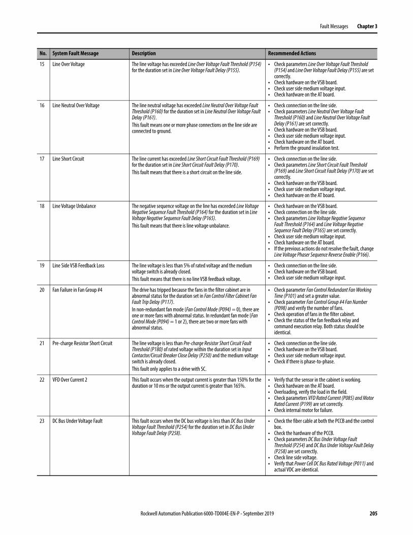
Fault Messages Chapter 3
15 Line Over Voltage The line voltage has exceeded Line Over Voltage Fault Threshold (P154) for the duration set in Line Over Voltage Fault Delay (P155).
• Check parameters Line Over Voltage Fault Threshold (P154) and Line Over Voltage Fault Delay (P155) are set correctly.
• Check hardware on the VSB board.• Check user side medium voltage input.• Check hardware on the AT board.
16 Line Neutral Over Voltage The line neutral voltage has exceeded Line Neutral Over Voltage Fault Threshold (P160) for the duration set in Line Neutral Over Voltage Fault Delay (P161).This fault means one or more phase connections on the line side are connected to ground.
• Check connection on the line side.• Check parameters Line Neutral Over Voltage Fault
Threshold (P160) and Line Neutral Over Voltage Fault Delay (P161) are set correctly.
• Check hardware on the VSB board.• Check user side medium voltage input.• Check hardware on the AT board.• Perform the ground insulation test.
17 Line Short Circuit The line current has exceeded Line Short Circuit Fault Threshold (P169) for the duration set in Line Short Circuit Fault Delay (P170).This fault means that there is a short circuit on the line side.
• Check connection on the line side.• Check parameters Line Short Circuit Fault Threshold
(P169) and Line Short Circuit Fault Delay (P170) are set correctly.
• Check hardware on the VSB board.• Check user side medium voltage input.• Check hardware on the AT board.
18 Line Voltage Unbalance The negative sequence voltage on the line has exceeded Line Voltage Negative Sequence Fault Threshold (P164) for the duration set in Line Voltage Negative Sequence Fault Delay (P165).This fault means that there is line voltage unbalance.
• Check hardware on the VSB board.• Check connection on the line side.• Check parameters Line Voltage Negative Sequence
Fault Threshold (P164) and Line Voltage Negative Sequence Fault Delay (P165) are set correctly.
• Check user side medium voltage input.• Check hardware on the AT board.• If the previous actions do not resolve the fault, change
Line Voltage Phaser Sequence Reverse Enable (P166).
19 Line Side VSB Feedback Loss The line voltage is less than 5% of rated voltage and the medium voltage switch is already closed.This fault means that there is no line VSB feedback voltage.
• Check connection on the line side.• Check hardware on the VSB board.• Check user side medium voltage input.
20 Fan Failure in Fan Group #4 The drive has tripped because the fans in the filter cabinet are in abnormal status for the duration set in Fan Control Filter Cabinet Fan Fault Trip Delay (P117). In non-redundant fan mode (Fan Control Mode (P094) = 0), there are one or more fans with abnormal status. In redundant fan mode (Fan Control Mode (P094) = 1 or 2), there are two or more fans with abnormal status.
• Check parameter Fan Control Redundant Fan Working Time (P101) and set a greater value.
• Check parameter Fan Control Group #4 Fan Number (P098) and verify the number of fans.
• Check operation of fans in the filter cabinet.• Check the status of the fan feedback relay and
command execution relay. Both status should be identical.
21 Pre-charge Resistor Short Circuit The line voltage is less than Pre-charge Resistor Short Circuit Fault Threshold (P180) of rated voltage within the duration set in Input Contactor/Circuit Breaker Close Delay (P250) and the medium voltage switch is already closed.This fault only applies to a drive with SC.
• Check connection on the line side.• Check hardware on the VSB board.• Check user side medium voltage input.• Check if there is phase-to-phase.
22 VFD Over Current 2 This fault occurs when the output current is greater than 150% for the duration or 10 ms or the output current is greater than 165%.
• Verify that the sensor in the cabinet is working.• Check hardware on the AT board.• Overloading, verify the load in the field.• Check parameters VFD Rated Current (P085) and Motor
Rated Current (P199) are set correctly.• Check internal motor for failure.
23 DC Bus Under Voltage Fault This fault occurs when the DC bus voltage is less than DC Bus Under Voltage Fault Threshold (P254) for the duration set in DC Bus Under Voltage Fault Delay (P258).
• Check the fiber cable at both the PCCB and the control box.
• Check the hardware of the PCCB.• Check parameters DC Bus Under Voltage Fault
Threshold (P254) and DC Bus Under Voltage Fault Delay (P258) are set correctly.
• Check line side voltage.• Verify that Power Cell DC Bus Rated Voltage (P011) and
actual VDC are identical.
No. System Fault Message Description Recommended Actions
Rockwell Automation Publication 6000-TD004E-EN-P - September 2019 205
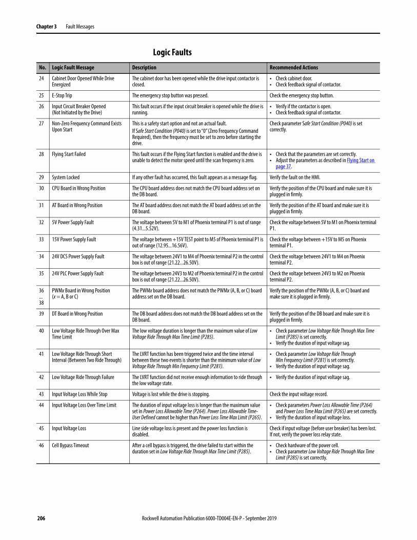
Chapter 3 Fault Messages
Logic FaultsNo. Logic Fault Message Description Recommended Actions
24 Cabinet Door Opened While Drive Energized
The cabinet door has been opened while the drive input contactor is closed.
• Check cabinet door.• Check feedback signal of contactor.
25 E-Stop Trip The emergency stop button was pressed. Check the emergency stop button.
26 Input Circuit Breaker Opened(Not Initiated by the Drive)
This fault occurs if the input circuit breaker is opened while the drive is running.
• Verify if the contactor is open.• Check feedback signal of contactor.
27 Non-Zero Frequency Command Exists Upon Start
This is a safety start option and not an actual fault.If Safe Start Condition (P040) is set to “0” (Zero Frequency Command Required), then the frequency must be set to zero before starting the drive.
Check parameter Safe Start Condition (P040) is set correctly.
28 Flying Start Failed This fault occurs if the Flying Start function is enabled and the drive is unable to detect the motor speed until the scan frequency is zero.
• Check that the parameters are set correctly.• Adjust the parameters as described in Flying Start on
page 37.
29 System Locked If any other fault has occurred, this fault appears as a message flag. Verify the fault on the HMI.
30 CPU Board in Wrong Position The CPU board address does not match the CPU board address set on the DB board.
Verify the position of the CPU board and make sure it is plugged in firmly.
31 AT Board in Wrong Position The AT board address does not match the AT board address set on the DB board.
Verify the position of the AT board and make sure it is plugged in firmly.
32 5V Power Supply Fault The voltage between 5V to M1 of Phoenix terminal P1 is out of range (4.31...5.52V).
Check the voltage between 5V to M1 on Phoenix terminal P1.
33 15V Power Supply Fault The voltage between +15V TEST point to M5 of Phoenix terminal P1 is out of range (12.95...16.56V).
Check the voltage between +15V to M5 on Phoenix terminal P1.
34 24V DCS Power Supply Fault The voltage between 24V1 to M4 of Phoenix terminal P2 in the control box is out of range (21.22...26.50V).
Check the voltage between 24V1 to M4 on Phoenix terminal P2.
35 24V PLC Power Supply Fault The voltage between 24V3 to M2 of Phoenix terminal P2 in the control box is out of range (21.22...26.50V).
Check the voltage between 24V3 to M2 on Phoenix terminal P2.
36...38
PWMx Board in Wrong Position(x = A, B or C)
The PWMx board address does not match the PWMx (A, B, or C) board address set on the DB board.
Verify the position of the PWMx (A, B, or C) board and make sure it is plugged in firmly.
39 DT Board in Wrong Position The DB board address does not match the DB board address set on the DB board.
Verify the position of the DB board and make sure it is plugged in firmly.
40 Low Voltage Ride Through Over Max Time Limit
The low voltage duration is longer than the maximum value of Low Voltage Ride Through Max Time Limit (P285).
• Check parameter Low Voltage Ride Through Max Time Limit (P285) is set correctly.
• Verify the duration of input voltage sag.
41 Low Voltage Ride Through Short Interval (Between Two Ride Through)
The LVRT function has been triggered twice and the time interval between these two events is shorter than the minimum value of Low Voltage Ride Through Min Frequency Limit (P281).
• Check parameter Low Voltage Ride Through Min Frequency Limit (P281) is set correctly.
• Verify the duration of input voltage sag.
42 Low Voltage Ride Through Failure The LVRT function did not receive enough information to ride through the low voltage state.
• Verify the duration of input voltage sag.
43 Input Voltage Loss While Stop Voltage is lost while the drive is stopping. Check the input voltage record.
44 Input Voltage Loss Over Time Limit The duration of input voltage loss is longer than the maximum value set in Power Loss Allowable Time (P264). Power Loss Allowable Time-User Defined cannot be higher than Power Loss Time Max Limit (P265).
• Check parameters Power Loss Allowable Time (P264) and Power Loss Time Max Limit (P265) are set correctly.
• Verify the duration of input voltage loss.
45 Input Voltage Loss Line side voltage loss is present and the power loss function is disabled.
Check if input voltage (before user breaker) has been lost. If not, verify the power loss relay state.
46 Cell Bypass Timeout After a cell bypass is triggered, the drive failed to start within the duration set in Low Voltage Ride Through Max Time Limit (P285).
• Check hardware of the power cell.• Check parameter Low Voltage Ride Through Max Time
Limit (P285) is set correctly.
206 Rockwell Automation Publication 6000-TD004E-EN-P - September 2019

Fault Messages Chapter 3
47 Cell Bypass Start Fault The power cell bypass was triggered and successfully executed, but the drive failed to restart automatically.This fault has two scenarios:1. Power cell bypass and low voltage ride through interval too short.2. Power cell bypass was triggered while drive was stopping normally.
• Check parameter Low Voltage Ride Through Min Time Interval (P281) is set correctly.
• Check hardware of the power cell.• Check if the power cell bypass and low voltage ride
through interval is too short.• Check if the power cell bypass was triggered while
drive was stopping normally.
48 Cell Bypass Logic Fault This fault has six scenarios:1. The power cell was bypassed but the drive did not send the bypass
command.2. When the bypass was triggered, a fault other than a bypass fault
occurred.3. There were two or more bypass faults in one phase.4. Power cell temperature timeout after bypass.5. Power cell was bypassed but the bypass cell number does not exist
in the control box.6. Drive bypassed but there is no bypass power cell.
• Check parameter Power Cell Bypass Upper Limit Time For Over Temperature (P057) is set correctly.
• Check configuration of power cells.• Check medium voltage status.
49...57
PWMA Board Not Compatible with PCCBAx Board(x = 1...9)
The firmware revision of the PWM board for the phase A leg of PowerFlex 6000 is not compatible with the firmware revision of the control board of the nth power unit for the phase A leg.Where nth corresponds to the PCCBAx (1...9) fault.
1. Read the firmware revision of the PWMA board and PCCBAx (1...9) board from the “Version Information” page on the HMI.
2. Check the major numbers of the above firmware revision. If they are not the same, replace the wrong board with the correct one.
58...66
PWMA Board Not Compatible with PCCBBx Board(x = 1...9)
The firmware revision of the PWM board for the phase B leg of PowerFlex 6000 is not compatible with the firmware revision of the control board of the nth power unit for the phase B leg.Where nth corresponds to the PCCBBx (1...9) fault.
1. Read the firmware revision of the PWMB board and PCCBBx (1...9) board from the “Version Information” page on the HMI.
2. Check the major numbers of the above firmware revision. If they are not the same, replace the wrong board with the correct one.
67...75
PWMA Board Not Compatible with PCCBCx Board(x = 1...9)
The firmware revision of the PWM board for the phase C leg of PowerFlex 6000 is not compatible with the firmware revision of the control board of the nth power unit for the phase C leg.Where nth corresponds to the PCCBCx (1...9) fault.
1. Read the firmware revision of the PWMC board and PCCBCx (1...9) board from the “Version Information” page on the HMI.
2. Check the major numbers of the above firmware revision. If they are not the same, replace the wrong board with the correct one.
76...78
Primary FPGA Not Compatible with PWMx Board(x = A, B, or C)
The firmware revision of the primary FPGA in the CPU board is not compatible with the firmware revision of the PWM board for the phase x leg of PowerFlex 6000.Where x corresponds to the PWMx (A, B, or C) fault.
1. Read the firmware revision of the primary FPGA and PWMx (A, B, or C) board from the “Version Information” page on the HMI.
2. Check the major numbers of the above firmware revision. If they are not the same, replace the wrong board with the correct one.
79 Primary FPGA Not Compatible with DT Board
The firmware revision of the primary FPGA in the CPU board is not compatible with the firmware revision of the DT board.
1. Read the firmware revision of the primary FPGA and DT board from the “Version Information” page on the HMI.
2. Check the major numbers of the above firmware revision. If they are not the same, replace the wrong board with the correct one.
80 Primary DSP Not Compatible with Primary FPGA
The firmware revision of the primary DSP is not compatible with the firmware revision of the primary FPGA in the CPU board.
1. Read the firmware revision of the DSP1 and primary FPGA from the “Version Information” page on the HMI.
2. Check the major numbers of the above firmware revision. If they are not the same, replace the wrong board with the correct one.
81 Primary DSP Not Compatible with Secondary DSP
The firmware revision of the primary DSP is not compatible with the firmware revision of the secondary DSP in the CPU board.
1. Read the firmware revision of the DSP1 and DSP2 from the “Version Information” page on the HMI.
2. Check the major numbers of the above firmware revision. If they are not the same, replace the wrong board with the correct one.
No. Logic Fault Message Description Recommended Actions
Rockwell Automation Publication 6000-TD004E-EN-P - September 2019 207
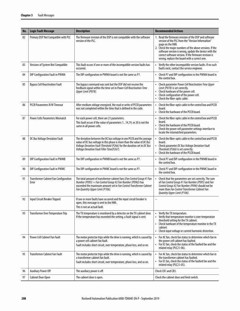
Chapter 3 Fault Messages
82 Primary DSP Not Compatible with PLC The firmware revision of the DSP is not compatible with the software version of the PLC.
1. Read the firmware revision of the DSP and software version of the PLC from the “Version Information” page on the HMI.
2. Check the major numbers of the above versions. If the software version is wrong, update the device with the correct software version. If the firmware revision is wrong, replace the board with a correct one.
83 Versions of System Not Compatible This fault occurs if one or more of the incompatible version faults has occurred.
• Verify the other incompatible version faults. If no such faults exist, contact the service engineer.
84 DIP Configuration Fault in PWMA The DIP configuration in PWMA board is not the same as P7. • Check P7 and DIP configuration in the PWMA board in the control box.
85 Bypass Cell Reactivation Fault The bypass command was sent but the DSP did not receive the feedback signal within the time set in Power Cell Reactivation Time Upper Limit (P078).
• Check parameter Power Cell Reactivation Time Upper Limit (P078) is set correctly.
• Check hardware of the power cell.• Check configuration of the power cell.• Check the fiber-optic cable.
86 PCCB Parameters R/W Timeout After medium voltage energized, the read or write of PCCB parameters was not completed within the time that is defined in the code.
• Check the fiber-optic cable in the control box and PCCB board.
• Check the hardware of the PCCB board.
87 Power Cells Parameters Mismatch For each power cell, there are 21 parameters.This fault occurs if the value of parameters 1...14,19, or 20 is not the same in all power cells.
• Check the fiber-optic cable in the control box and PCCB board.
• Check the hardware of the PCCB board.• Check the power cell parameter settings interface to
locate the mismatched parameters.
88 DC Bus Voltage Deviation Fault The deviation between the DC bus voltage in one PCCB and the average value of DC bus voltage in this phase is more than the value of DC Bus Voltage Deviation Fault Threshold (P266) for the duration set in DC Bus Voltage Deviation Fault Filter Time(P267).
• Check the fiber-optic cable in the control box and PCCB board.
• Check parameter DC Bus Voltage Deviation Fault Threshold (P266) is set correctly.
• Check the hardware of the PCCB board.
89 DIP Configuration Fault in PWMB The DIP configuration in PWMB board is not the same as P7. • Check P7 and DIP configuration in the PWMB board in the control box.
90 DIP Configuration Fault in PWMC The DIP configuration in PWMC board is not the same as P7. • Check P7 and DIP configuration in the PWMC board in the control box.
91 Transformer Cabinet Fan Configuration Error
The total amount of transformer cabinet fans (Fan Control Group #1 Fan Number (P095) + Fan Control Group #2 Fan Number (P096)) has exceeded the maximum amount set in Fan Control Transformer Cabinet Fan Quantity Upper Limit (P106).
• Check that the parameters are set correctly. The sum of Fan Control Group #1 Fan Number (P095) and Fan Control Group #2 Fan Number (P096) should not be more than Fan Control Transformer Cabinet Fan Quantity Upper Limit (P106).
92 Input Circuit Breaker Tripped If one or more faults have occurred and the input circuit breaker is open, this message is sent to the HMI.This is not an actual fault.
–
93 Transformer Over Temperature Trip The TX temperature is monitored by a detector on the TX cabinet door. If the temperature has exceeded the setting, a fault signal is sent.
• Verify the TX temperature.• Verify that temperature monitor is over temperature
threshold setting for the TX cabinet.• Check hardware of the temperature monitor in the TX
cabinet.• Check input voltage or current harmonic distortion.
94 Power Cell Cabinet Fan Fault The motor protector trips while the drive is running, which is caused by a power cell cabinet fan fault.Fault includes short circuit, over temperature, phase loss, and so on.
• For AC fan, check fan status to determine which fan in the power cell cabinet has faulted.
• For EC fan, check the status of the faulted fan and the related relay (PLC2 I-06).
95 Transformer Cabinet Fan Fault The motor protector trips while the drive is running, which is caused by a transformer cabinet fan fault.Fault includes short circuit, over temperature, phase loss, and so on.
• For AC fan, check fan status to determine which fan in the transformer cabinet has faulted.
• For EC fan, check the status of the faulted fan and the related relay (PLC2 I-05).
96 Auxiliary Power Off The auxiliary power is off. Check CB1 and CB3.
97 Cabinet Door Open The cabinet door is open. Check the cabinet door and limit switch.
No. Logic Fault Message Description Recommended Actions
208 Rockwell Automation Publication 6000-TD004E-EN-P - September 2019

Fault Messages Chapter 3
98 Cooling Fan Contactor Open The cooling fan contactor is opened while the drive is running.This fault only applies to the UL version of the PowerFlex 6000 drive.
Check fan contactor.
99 DCS Communication Error There is a DCS communication error. Check the communication cable between the DCS and drive.
100 Motor Over Temperature The motor is over temperature.This fault only applies to a motor with the NT538 temperature monitor. If the temperature monitor is not present, check the related terminal on the PLC if connected to power.
Check the motor temperature.
101 Filter Cabinet Over Temperature The filter cabinet is over temperature. • Verify the temperature of the filter cabinet.• Verify that temperature monitor is over temperature
threshold setting for the filter cabinet.• Check hardware of the temperature monitor in the
filter cabinet.
102 Motor Side HECS Power Supply Fault There is a short circuit in the motor side HECS power supply. • Check the power supply of the motor side HECS.• Check the relay status.• Check the connection between the relay and PLC.• Check the HECS.
No. Logic Fault Message Description Recommended Actions
Rockwell Automation Publication 6000-TD004E-EN-P - September 2019 209
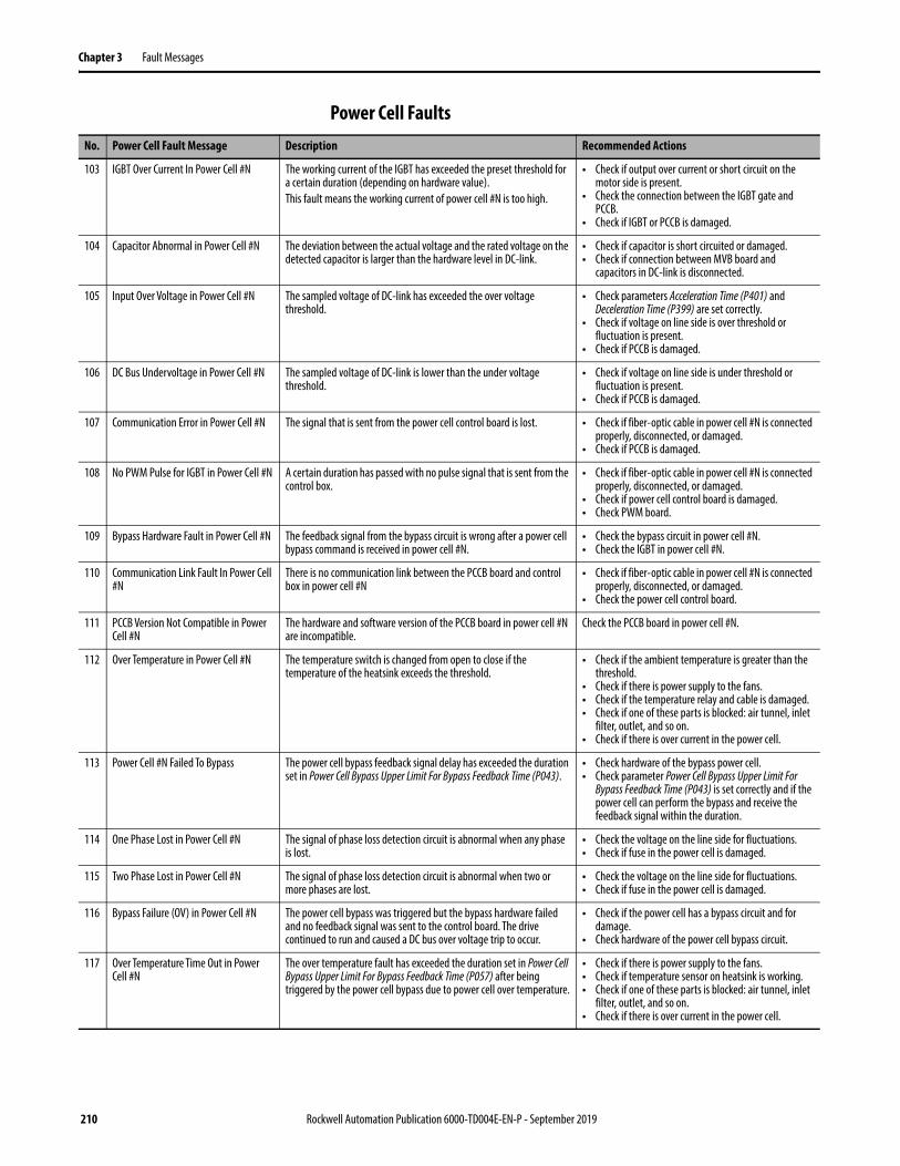
Chapter 3 Fault Messages
Power Cell FaultsNo. Power Cell Fault Message Description Recommended Actions
103 IGBT Over Current In Power Cell #N The working current of the IGBT has exceeded the preset threshold for a certain duration (depending on hardware value).This fault means the working current of power cell #N is too high.
• Check if output over current or short circuit on the motor side is present.
• Check the connection between the IGBT gate and PCCB.
• Check if IGBT or PCCB is damaged.
104 Capacitor Abnormal in Power Cell #N The deviation between the actual voltage and the rated voltage on the detected capacitor is larger than the hardware level in DC-link.
• Check if capacitor is short circuited or damaged.• Check if connection between MVB board and
capacitors in DC-link is disconnected.
105 Input Over Voltage in Power Cell #N The sampled voltage of DC-link has exceeded the over voltage threshold.
• Check parameters Acceleration Time (P401) and Deceleration Time (P399) are set correctly.
• Check if voltage on line side is over threshold or fluctuation is present.
• Check if PCCB is damaged.
106 DC Bus Undervoltage in Power Cell #N The sampled voltage of DC-link is lower than the under voltage threshold.
• Check if voltage on line side is under threshold or fluctuation is present.
• Check if PCCB is damaged.
107 Communication Error in Power Cell #N The signal that is sent from the power cell control board is lost. • Check if fiber-optic cable in power cell #N is connected properly, disconnected, or damaged.
• Check if PCCB is damaged.
108 No PWM Pulse for IGBT in Power Cell #N A certain duration has passed with no pulse signal that is sent from the control box.
• Check if fiber-optic cable in power cell #N is connected properly, disconnected, or damaged.
• Check if power cell control board is damaged.• Check PWM board.
109 Bypass Hardware Fault in Power Cell #N The feedback signal from the bypass circuit is wrong after a power cell bypass command is received in power cell #N.
• Check the bypass circuit in power cell #N.• Check the IGBT in power cell #N.
110 Communication Link Fault In Power Cell #N
There is no communication link between the PCCB board and control box in power cell #N
• Check if fiber-optic cable in power cell #N is connected properly, disconnected, or damaged.
• Check the power cell control board.
111 PCCB Version Not Compatible in Power Cell #N
The hardware and software version of the PCCB board in power cell #N are incompatible.
Check the PCCB board in power cell #N.
112 Over Temperature in Power Cell #N The temperature switch is changed from open to close if the temperature of the heatsink exceeds the threshold.
• Check if the ambient temperature is greater than the threshold.
• Check if there is power supply to the fans.• Check if the temperature relay and cable is damaged.• Check if one of these parts is blocked: air tunnel, inlet
filter, outlet, and so on.• Check if there is over current in the power cell.
113 Power Cell #N Failed To Bypass The power cell bypass feedback signal delay has exceeded the duration set in Power Cell Bypass Upper Limit For Bypass Feedback Time (P043).
• Check hardware of the bypass power cell.• Check parameter Power Cell Bypass Upper Limit For
Bypass Feedback Time (P043) is set correctly and if the power cell can perform the bypass and receive the feedback signal within the duration.
114 One Phase Lost in Power Cell #N The signal of phase loss detection circuit is abnormal when any phase is lost.
• Check the voltage on the line side for fluctuations.• Check if fuse in the power cell is damaged.
115 Two Phase Lost in Power Cell #N The signal of phase loss detection circuit is abnormal when two or more phases are lost.
• Check the voltage on the line side for fluctuations.• Check if fuse in the power cell is damaged.
116 Bypass Failure (OV) in Power Cell #N The power cell bypass was triggered but the bypass hardware failed and no feedback signal was sent to the control board. The drive continued to run and caused a DC bus over voltage trip to occur.
• Check if the power cell has a bypass circuit and for damage.
• Check hardware of the power cell bypass circuit.
117 Over Temperature Time Out in Power Cell #N
The over temperature fault has exceeded the duration set in Power Cell Bypass Upper Limit For Bypass Feedback Time (P057) after being triggered by the power cell bypass due to power cell over temperature.
• Check if there is power supply to the fans.• Check if temperature sensor on heatsink is working.• Check if one of these parts is blocked: air tunnel, inlet
filter, outlet, and so on.• Check if there is over current in the power cell.
210 Rockwell Automation Publication 6000-TD004E-EN-P - September 2019
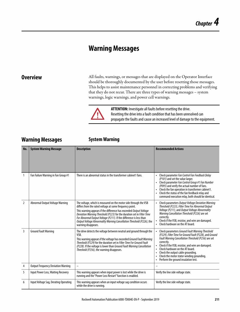
Chapter 4
Warning Messages
Overview All faults, warnings, or messages that are displayed on the Operator Interface should be thoroughly documented by the user before resetting those messages. This helps to assist maintenance personnel in correcting problems and verifying that they do not recur. There are three types of warning messages – system warnings, logic warnings, and power cell warnings.
Warning Messages System Warning
ATTENTION: Investigate all faults before resetting the drive. Resetting the drive into a fault condition that has been unresolved can propagate the faults and cause an increased level of damage to the equipment.
No. System Warning Message Description Recommended Actions
1 Fan Failure Warning in Fan Group #1 There is an abnormal status in the transformer cabinet1 fans. • Check parameter Fan Control Fan Feedback Delay (P101) and set the value larger.
• Check parameter Fan Control Group #1 Fan Number (P095) and verify the actual number of fans.
• Check the fan operation in transformer cabinet1.• Check the status of the fan feedback relay and
command execution relay, both should be identical.
2 Abnormal Output Voltage Warning The voltage, which is measured on the motor side through the VSB differs from the rated voltage at some frequency point.This warning appears if the difference has exceeded Output Voltage Deviation Warning Threshold (P223) for the duration set in Filter Time For Abnormal Output Voltage (P211). If the difference is less than Output Voltage Abnormality Warning Cancellation Threshold (P226), the warning disappears.
• Check parameters Output Voltage Deviation Warning Threshold (P223), Filter Time For Abnormal Output Voltage (P211), and Output Voltage Abnormality Warning Cancellation Threshold (P226) are set correctly.
• Check if the VSB, resistor, and wire are damaged.• Check hardware on the AT board.
3 Ground Fault Warning The drive detects the voltage between neutral and ground through the VSB.This warning appears if the voltage has exceeded Ground Fault Warning Threshold (P229) for the duration set in Filter Time For Ground Fault (P228). If the voltage is lower than Ground Fault Warning Cancellation Threshold (P256), the warning disappears.
• Check parameters Ground Fault Warning Threshold (P229), Filter Time For Ground Fault (P228), and Ground Fault Warning Cancellation Threshold (P256) are set correctly.
• Check if the VSB, resistor, and wire are damaged.• Check hardware on the AT board.• Check the output cable grounding.• Check the motor stator winding grounding.• Perform the ground insulation test.
4 Output Frequency Deviation Warning – –
5 Input Power Loss, Waiting Recovery This warning appears when input power is lost while the drive is running and the “Power Loss Restart” function is enabled.
Verify the line side voltage state.
6 Input Voltage Sag, Derating Operating This warning appears when an input voltage sag condition occurs while the drive is running.
Verify the line side voltage state.
Rockwell Automation Publication 6000-TD004E-EN-P - September 2019 211
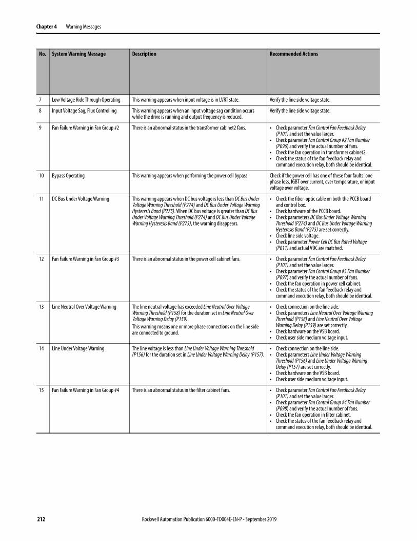
Chapter 4 Warning Messages
7 Low Voltage Ride Through Operating This warning appears when input voltage is in LVRT state. Verify the line side voltage state.
8 Input Voltage Sag, Flux Controlling This warning appears when an input voltage sag condition occurs while the drive is running and output frequency is reduced.
Verify the line side voltage state.
9 Fan Failure Warning in Fan Group #2 There is an abnormal status in the transformer cabinet2 fans. • Check parameter Fan Control Fan Feedback Delay (P101) and set the value larger.
• Check parameter Fan Control Group #2 Fan Number (P096) and verify the actual number of fans.
• Check the fan operation in transformer cabinet2.• Check the status of the fan feedback relay and
command execution relay, both should be identical.
10 Bypass Operating This warning appears when performing the power cell bypass. Check if the power cell has one of these four faults: one phase loss, IGBT over current, over temperature, or input voltage over voltage.
11 DC Bus Under Voltage Warning This warning appears when DC bus voltage is less than DC Bus Under Voltage Warning Threshold (P274) and DC Bus Under Voltage Warning Hysteresis Band (P275). When DC bus voltage is greater than DC Bus Under Voltage Warning Threshold (P274) and DC Bus Under Voltage Warning Hysteresis Band (P275), the warning disappears.
• Check the fiber-optic cable on both the PCCB board and control box.
• Check hardware of the PCCB board.• Check parameters DC Bus Under Voltage Warning
Threshold (P274) and DC Bus Under Voltage Warning Hysteresis Band (P275) are set correctly.
• Check line side voltage.• Check parameter Power Cell DC Bus Rated Voltage
(P011) and actual VDC are matched.
12 Fan Failure Warning in Fan Group #3 There is an abnormal status in the power cell cabinet fans. • Check parameter Fan Control Fan Feedback Delay (P101) and set the value larger.
• Check parameter Fan Control Group #3 Fan Number (P097) and verify the actual number of fans.
• Check the fan operation in power cell cabinet.• Check the status of the fan feedback relay and
command execution relay, both should be identical.
13 Line Neutral Over Voltage Warning The line neutral voltage has exceeded Line Neutral Over Voltage Warning Threshold (P158) for the duration set in Line Neutral Over Voltage Warning Delay (P159).This warning means one or more phase connections on the line side are connected to ground.
• Check connection on the line side.• Check parameters Line Neutral Over Voltage Warning
Threshold (P158) and Line Neutral Over Voltage Warning Delay (P159) are set correctly.
• Check hardware on the VSB board.• Check user side medium voltage input.
14 Line Under Voltage Warning The line voltage is less than Line Under Voltage Warning Threshold (P156) for the duration set in Line Under Voltage Warning Delay (P157).
• Check connection on the line side.• Check parameters Line Under Voltage Warning
Threshold (P156) and Line Under Voltage Warning Delay (P157) are set correctly.
• Check hardware on the VSB board.• Check user side medium voltage input.
15 Fan Failure Warning in Fan Group #4 There is an abnormal status in the filter cabinet fans. • Check parameter Fan Control Fan Feedback Delay (P101) and set the value larger.
• Check parameter Fan Control Group #4 Fan Number (P098) and verify the actual number of fans.
• Check the fan operation in filter cabinet.• Check the status of the fan feedback relay and
command execution relay, both should be identical.
No. System Warning Message Description Recommended Actions
212 Rockwell Automation Publication 6000-TD004E-EN-P - September 2019

Warning Messages Chapter 4
Logic WarningNo. Logic Warning Message Description Recommended Actions
16 DSP Communication Error There is a communication error between the PLC and DSP. • Check connection between the drive and PLC.• Check receive and transmit LED status on CPU board.
17 PLC Communication Error There is a communication error between the PLC and HMI. Check connection between the HMI and PLC.
18 HMI Version Incompatible The versions of the HMI and PLC are not compatible. Check the versions of the HMI and PLC.
19 Transformer Over Temperature Warning The transformer is over temperature. • Check the transformer and transformer cabinet fan.• Check configuration of the transformer monitor.
20 Power Cell Cabinet Fan Circuit Breaker Open
This warning appears when the MV is energized while the power cell cabinet fan circuit breaker is open.
Check the power cell cabinet fan circuit breaker. It should be closed before the MV is energized.
21 Transformer Cabinet Fan Circuit Breaker Open
This warning appears when the MV is energized while the transformer cabinet fan circuit breaker is open.
Check the transformer cabinet fan circuit breaker. It should be closed before the MV is energized.
22 External Control Power Loss Warning Control power usually comes from the user side and the transformer acts as a backup.This warning appears when the user side does not supply control power and the transformer is used.
• Check user side control power.• Check status of UPS.
23 Analog Channel #1 Loss Warning There is signal loss in analog channel #1 (4-20 mA). • Check wiring of analog channel #1.• Check if 4-20 mA signal from user side is present.
24 DCS Communication Error Warning This warning appears if the control mode is set to DCS (Owner #2 Selection (P476) = 15) and DCS communication is interrupted.
Check communication cable between the user side and drive.
25 Analog Feedback Loss Warning This warning appears when the PID function is enabled and there is no analog feedback.
• Check wiring between the user side and drive.• Check if 4-20 mA signal from user side is present.
26 Analog Channel #2 Loss Warning There is signal loss in analog channel #2 (4-20 mA).Analog channel #2 is the analog signal input backup.When User Analog Set-point Switch (P494) = 1, this analog channel is used as the 4-20 mA input.
• Check wiring of analog channel #2.• Check if 4-20 mA signal from user side is present.
Rockwell Automation Publication 6000-TD004E-EN-P - September 2019 213
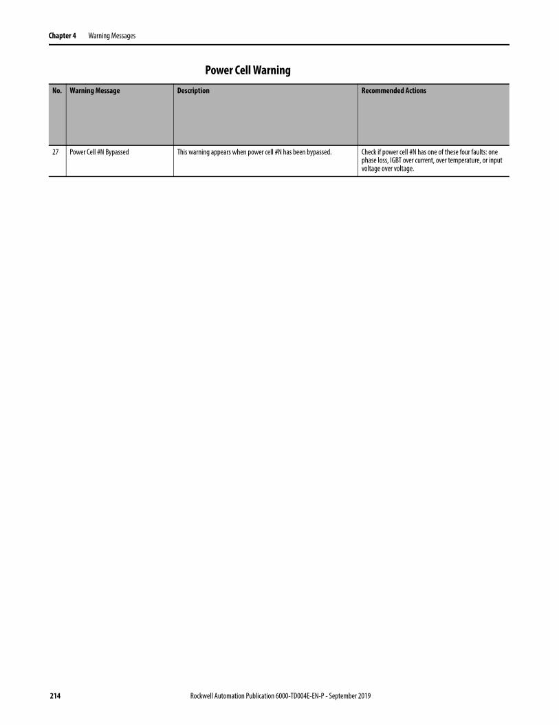
Chapter 4 Warning Messages
Power Cell WarningNo. Warning Message Description Recommended Actions
27 Power Cell #N Bypassed This warning appears when power cell #N has been bypassed. Check if power cell #N has one of these four faults: one phase loss, IGBT over current, over temperature, or input voltage over voltage.
214 Rockwell Automation Publication 6000-TD004E-EN-P - September 2019


Publication 6000-TD004E-EN-P - September 2019 Supersedes Publication 6000-TD004D-EN-P - November 2017 Copyright © 2019 Rockwell Automation, Inc. All rights reserved. Printed in Canada.
Rockwell Automation Support
Rockwell Automation provides technical information on the Web to assist you in using its products.At http://www.rockwellautomation.com/support you can find technical and application notes, sample code, and links to software service packs. You can also visit our Support Center at https://rockwellautomation.custhelp.com/ for software updates, support chats and forums, technical information, FAQs, and to sign up for product notification updates.
In addition, we offer multiple support programs for installation, configuration, and troubleshooting. For more information, contact your local distributor or Rockwell Automation representative, or visithttp://www.rockwellautomation.com/services/online-phone.
Installation Assistance
If you experience a problem within the first 24 hours of installation, review the information that is contained in this manual. You can contact Customer Support for initial help in getting your product up and running.
New Product Satisfaction Return
Rockwell Automation tests all of its products to help ensure that they are fully operational when shipped from the manufacturing facility. However, if your product is not functioning and needs to be returned, follow these procedures.
Documentation Feedback
Your comments will help us serve your documentation needs better. If you have any suggestions on how to improve this document, complete this form, publication RA-DU002, available at http://www.rockwellautomation.com/literature/.
United States or Canada 1.440.646.3434
Outside United States or Canada Use the Worldwide Locator at http://www.rockwellautomation.com/rockwellautomation/support/overview.page, or contact your local Rockwell Automation representative.
United States Contact your distributor. You must provide a Customer Support case number (call the phone number above to obtain one) to your distributor to complete the return process.
Outside United States Please contact your local Rockwell Automation representative for the return procedure.
Medium Voltage Products, 135 Dundas Street, Cambridge, ON, N1R 5X1 Canada, Tel: (1) 519.740.4100, Fax: (1) 519.623.8930Online: www.ab.com/mvb
Allen-Bradley, PowerFlex, Rockwell Automation, Rockwell Software, and TechConnect are trademarks of Rockwell Automation, Inc.
Trademarks not belonging to Rockwell Automation are property of their respective companies.
Rockwell Automation maintains current product environmental information on its website athttp://www.rockwellautomation.com/rockwellautomation/about-us/sustainability-ethics/product-environmental-compliance.page.