6.0 preliminary design for thermal treatment 6.1
TRANSCRIPT

6.0 PRELIMINARY DESIGN FOR THERMAL TREATMENT
Thermal treatment will be performed to support the SOU remedial action. This section describesthe selected processes for thermal treatment and discusses the design criteria for that ponion ofthe remedy.
6.1. DESCRIPTION OF REMEDY
Thermal treatment has been selected as the remedy for treating PCB- and VOC-contaminatedsediments in Fields Brook. This section describes the remedial design of systems required toachieve this treatment.
6.1.1 Engineering Studies
Thermal Treatment Design Investigation
Summary. The results of the TTDI indicated that Fields Brook sediments can successfully beprocessed to meet the applicable sediment treatment standards using thermal treatmenttechnology. The sediments must be heated to a minimum temperature of 700eF to meet the PCBtreatment standard. The study indicated that simple air drying would reduce the volatile organicconstituents to concentrations less than the applicable treatment standards.
Objectives. The overall objective of the TTDI studies was to obtain data for preparing aperformance-based specification for a full-scale thermal treatment system. Specific objectives ofthe TTDI were to:
• Identify locations in Fields Brook that contain sediments with PCBs and/or VOCs atconcentrations that exceed the cleanup goals and represent the highest concentrations of theseconstituents
A91I6- i
• Sample sediments from these locations, perform various analyses to characterize the sediments,and conduct treatability testing to evaluate the effect of thermal treatment on the characteristicsof these sediments
• Determine approximate quantities of sediments that will require thermal treatment
• Determine the effect of sediment treatment temperature and residence time (at sedimenttreatment temperature) on the total concentration of PCBs in the treated sediment
• Determine the residual concentrations of selected VOCs and SVOCs in the untreated andtreated sediment
• Determine concentrations of dioxins and furans, expressed as TCDD^, in the untreated andtreated sediment
• Determine the degree of metals partitioning from the sediment to the gas phase
• Perform TCLP on all compounds with TCLP criteria in the treated sediment
• Evaluate the geotechnical characteristics of the treated sediment to determine load bearingcapacities
Sampling, Field tests for VOCs and PCBs were used to select samples for the treatability testingthat met the objective of containing these constituents at the highest concentrations found in thesampling regions. The resulting sediments were sampled in the field, and the samples wereshipped to Hazelton Environmental Services for VOC and PCB analysis. The bulk sedimentswere shipped to International Technology Corporation, Technology Development Laboratory inKnoxville, Tennessee (ITTDK) for thermal treatability testing. ITTDK took samples of theas-received bulk sediments for VOC and PCB analysis. Based on the results of these analysesand previous particle size distributions measured on sediments from these reaches, the sediment
A9U t ^2/20/95 6:24pn 6-2

from reach 5-1/2 was eliminated from the testing because it has a similar panicle size distributionto that of reach 5-2/14 and did not contain any VOCs.
Sediment characterization. Table 6-1 summarizes the sediment characterization from the TTDI.As-received samples were prepared for thermal treatability testing by homogenizing and drying ina hood to lower the moisture content of the sediments for easier handling. The preparedsediment was sampled and analyzed for various parameters including PCBs, VOCs, and SVOCs.
Screening tests. Static tray tests were conducted on the prepared sediment to evaluate the effectof residence time and temperature on the concentrations of PCBs in the sediment. A total of 9tray tests were conducted (3 temperatures and 3 residence times). The sediment temperaturestested were 700, 1,000, and 1,300°F. The residence times were measured as residence time atthe target sediment temperature and included 0, 10, and 30 minutes. The residence time to reachthe target sediment temperature ranged from 15 to 20 minutes, and the total residence timeranged from 15 to 50 minutes. The treated sediment from each tray test was analyzed for PCBs.
Bench-scale test. Based on the* results of the tray tests, target sediment temperatures andresidence times were established for conducting rotary thermal apparatus tests that more closelyemulate heat and mass transfer conditions in a full-scale unit. The conditions chosen were 700and 1,000°F sediment temperature and no residence time at the target sediment temperature.Treated sediments from the rotary thermal apparatus tests were analyzed for various parametersand compared with the analytical results for the prepared sediment to determine the effect of thethermal treatment on these various parameters.
Results. The three sediment samples received from the field were determined to contain PCBs atthe following concentrations:
• Reach 5-1/2 - 140 mg/kg• Reach 5-2/14 - 260 mg/kg• Reach 6 - 140 mg/kg
2/3VW 6:24pm 6-3
Concentrations of VOCs were determined to be below the residential cleanup goal, except fortetrachloroethene in the sediment from reach 5-2/14 and vinyl chloride in the sediment fromreach 6.
Samples taken after the preparation step (homogenization and drying in the hood) indicated thatconcentrations of VOCs had decreased significantly during the drying step (average of 90 percentconcentration reduction for VOCs, with starting concentrations in excess of 10 mg/kg). After thepreparation step, all VOC concentrations were less than the residential cleanup goals.Hexachlorobenzene was the only SVOC determined to be in excess of the residential cleanup goalin the prepared sediment; this was true for sediments from both reaches 5-2/14 and 6.
The PCB concentration was approximately 200 mg/kg in the prepared sediment for both reachestested. The treated sediment from all three tray tests at 700°F contained detectable PCBs atconcentrations less than 1.8 mg/kg using Method 8080. PCBs were not detected in any of thetreated sediments from the 1,000 and 1,300°F tray test runs.
The organic carbon content of the prepared sediment was approximately 4.6 percent byweight for both sediments tested. The concentrations of organic carbon in the treated sedimentfrom the RTA test runs were reduced 70 percent in the 700°F test run and reduced 84 percent inthe 1,000°F test run.
Concentrations of all organic constituents of concern were found to be less than the residentialcleanup goal for all treated sediments from the rotary thermal apparatus test runs, includingPCBs. PCBs were verified to be present in the treated sediment from the 700°F test run but atconcentrations less than 1.3 mg/kg.
Dioxins and furans were detected in the prepared sediment from both reaches at concentrationsless than 1 pg/kg, expressed as TCDD^. The concentrations of dioxins and furans in thesediment decreased during thermal treatment (i.e., 60 percent reduction at a sediment treatment
AMI2/20/95 6:24pm 6~4

temperature of 700°F and 99 percent reduction at a sediment treatment temperature of 1,000°F,justifying that 1,000°F is the appropriate operating temperature).
Remedial Design Approach
The remedial design for the thermal treatment of specific contaminated sediments will include thegeneration of a set of performance-based specifications for thermal treatment services,procurement of the services of a thermal treatment contractor, and fmalization of designdocuments based on the characteristics of the chosen contractor's equipment.
The performance-based specifications will define the performance requirements that must beachieved by the thermal treatment contractor during the remedial action. In addition toperformance requirements, the specifications will define requirements for preparation of otherrequired deliverables that must be developed by the contractor to complete the remedial design; asignificant portion of the design information will be required in these submittals. Deliverablespotentially required include:
• Trial burn plan• Safety and health plan• Process flow diagrams• Piping and instrumentation diagrams• Instrumentation and control drawings• Equipment layout plan
• Schedule• Regulatory compliance plan• Contingency plan• Construction quality assurance plan• Spill control plan• Performance verification plan• Field sampling and analysis plan
6:24pm 6~5

• Stormwater pollution prevention plan• Material handling plan (including fugitive emissions control)
• Wastewater treatment plan• Thermal relief management plan
Contractor procurement will consist of the following steps: (1) contractor prequalification,(2) issuing Request for Proposal packages to contractors, (3) prebid meeting/site tour,(4) contractor proposal preparation, (5) proposal evaluation, and (6) contract negotiation.Contractors will be prequalified based on both the characteristics of their commercially availablethermal treatment equipment and experience in performing remedial actions at sites with similarsoil volumes and types and concentrations of contaminants. These data will be obtained from adatabase that is maintained by Focus Environmental, Inc. The Request for Proposal packageswill include three components: instructions to bidders, technical specifications, and contract.Proposals will be evaluated using a scoring system that allocates points for specific itemsincluding, but not limited to, organizational structure and staffing plan, equipment designcharacteristics, equipment performance data, project schedule, experience with similar thermaltreatment projects, project commitments, and financial status.
The information contained in this 30 percent design report provides the technical basis forpreparing the performance specifications during subsequent design work associated with thethermal treatment of Fields Brook sediments.
6.1.2 Msyor Processes and Equipment
Several different commercially available thermal treatment systems may be used for the full-scaletreatment of PCB-contaminated sediments at the Fields Brook site. This section summarizesexisting data on the application of thermal treatment technologies at other PCB-contaminatedsites.
A9112/20/95 6:24pm

The ROD for the Fields Brook site specifies onsite thermal treatment as the remedial technology.When the ROD was written (1986), incineration was the only well-proven thermal treatmenttechnology. Since then, a number of types of thermal desorption systems have been developedand demonstrated on PCB-contaminated soil and sediment applications. Based on the successful
application of thermal desorption technologies for treating PCB-contaminated soils and sedimentsat other sites, some types of thermal desorption systems have been demonstrated to achieve levelscomparable to the performance standards established for the Fields Brook site. This 30 percentremedial design has been developed with the assumption that either incineration or thermaldesorption systems could be used at the site. Therefore, this report uses the term "thermaltreatment systems/ which includes both incineration and thermal desorption systems. Use of athermal desorption system would require EPA to issue either an Explanation of SignificantDifferences or a ROD modification.
Comparison of Thermal Desorption and Incineration
Table 6-2 summarizes the differences between incineration and thermal desorption systems. Ingeneral, differences lie in the types of waste that can be treated, process operating parameters,and mechanical features.
Selection of a thermal treatment system for the Fields Brook site will depend primarily on thefollowing criteria:
• Capability of meeting sediment performance criteria• Capability of meeting applicable air emission standards• Mobility• Community acceptance• Cost
Sediment performance criteria are specified in the TTDI for residual levels of PCBs, VOCs, andSVOCs. To achieve these standards, the selected thermal treatment systems would need to
2/3IV9S ft 6*7

de.nonstrate the capability of consistently operating at or above temperatures ranging from greater
than 700°F to 1,000°F and at total soil residence times of approximately 10 to 30 minutes.
Differences exist between the air emission standards that apply to incinerators and those thatapply to thermal desorbers. The selected thermal treatment vendor must demonstrate thecapability of his system to meet applicable air emission standards. Air emission standards foreach technology are discussed in Section 6.2.3.
Representative Thermal Treatment Systems
TTDI results indicate that the optimum ranges for treatment temperature and residence time forachieving the sediment cleanup criteria for the PCB-contaminated sediments are between 700 and1,000°F and 30 to 40 minutes, respectively. All incinerators are easily capable of achievingthese temperatures and residence times. Several types of thermal desorption systems are alsocapable of operating within this soil treatment temperature range.
Table 6-3 lists the thermal treatment systems that are capable of operating within the projectedtemperature range for processing the PCB-contaminated sediments at the Fields Brook site. Thethermal treatment systems listed in Table 6-3 are examples selected to present an overview of thetypes of processes and operational characteristics of thermal treatment systems that are potentiallyapplicable for remediation of the Fields Brook site. There are a number of additional vendors ofthermal treatment systems similar to those listed in Table 6-3.
Frequency of Application of Thermal Technologies at PCB-Contaminated Sites
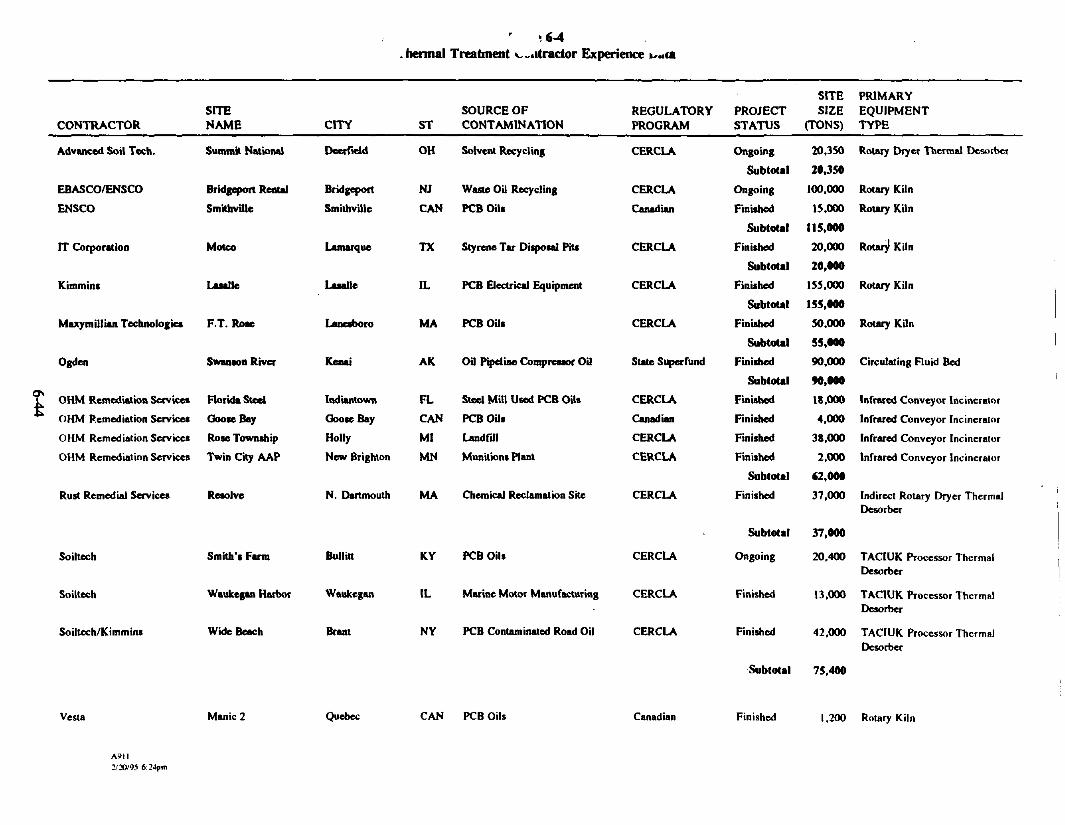
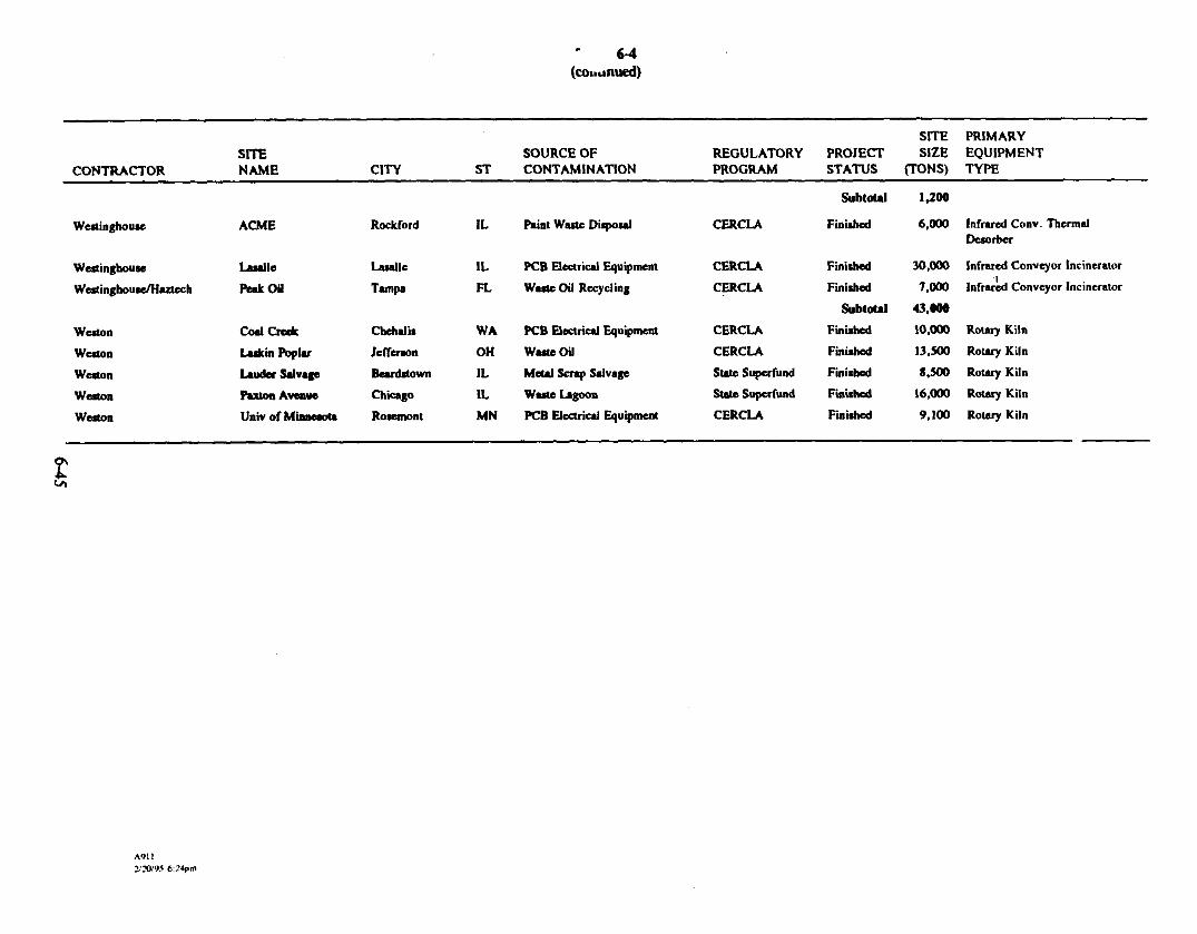
Table 6-4 lists the PCB-contaminated sites for which thermal treatment has been specified in aROD. This information was taken from a database maintained by Focus Environmental, Inc. totrack the application of thermal treatment technologies for remediating contaminated sediments.Figure 6-1 illustrates a frequency distribution of the use of different types of thermal treatmenttechnologies at PCB-contaminated sites. The distribution is based on the 25 thermal treatment
AMI1/3V95 6:24pm 6-8

projects iisted in Table 6-4. Figure 6-1 shows that rotary kilns are the most widely appliedthermal treatment systems at PCB-contaminated sites; infrared conveyor furnaces are the secondmost frequently applied. The information presented in Figure 6-1 provides justification forselecting rotary kiln incineration technology with thermal treatment, as specified by the ROD.
Figure 6-2 illustrates a frequency distribution of site sizes for projects for which onsite thermaltreatment has been used for remediating PCB-contaminated sites. The figure indicates that onsitethermal treatment is rarely used in the remediation of sites with soil quantities at or less than1,000 tons.
To be cost-effective at sites with low volumes of contaminated materials, the selected thermaltreatment systems must be highly mobile. The thermal capacity of a system is a good indicatorof its mobility. The smaller the system capacity, the smaller the number of trailers required tomobilize the unit. Mobilization and demobilization costs are greatly reduced if the equipment istrailer mounted and few trailers (less than 4) are required to mobilize the unit.
Based on the site and waste characteristics and the historical applications summarized inTable 6-4 and Figures 6-1 and 6-2, rotary kiln incineration will likely be the thermal treatmenttechnology applied to the remediation of the Fields Brook sediments.
Example Rotary Kiln Incineration Technology
The Vesta Unit 100 is an example of rotary kiln incineration technology that may be applied atthe Fields Brook site. It represents a cost-effective technology because it is a small,trailer-mounted unit with relatively low mobilization and demobilization costs.
Figure 6-3 illustrates a process flow diagram for the Vesta Unit 100 incinerator. The Vesta Unit100 is a transportable incineration process for treating sediments and soils contaminated withhalogenated VOCs/SVOCs, nonhalogenated VOCs/SVOCs, PCBs, and pesticides/herbicides.The Vesta Unit 100 is rated at 1 to 2 tons/hr and has an overall thermal duty of 10 MM Btu/hr.
A91I2/2QW 6:24pm 6-9

The unit is trailer-mounted, requiring a 65- by 85-ft area for setup. The system consists of arotary kiln incinerator, followed by an secondary combustion chamber (SCC) for completedestruction of a wide range of organic contaminants. The process flue gas is passed through anair pollution control (APC) system before release to the atmosphere. Two diesel generators areused to supply backup power.
The Vesta Unit 100 uses a refractory-lined rotary kiln incinerator and is capable of operating atrelatively high temperatures up to 1,500°F for 24 hours a day, 7 days a week. The rotary kiln is4.33 ft in diameter and 25 ft long and is equipped with a 5-MM Btu/hr burner. The rotary kilncan be heated by an oxygen-fuel burner with either fuel oil, natural gas, or liquefied propane.The burner is fired directly into the kiln, counter-current to the direction of sediment movement.The treated sediment exits the burner end of the kiln and falls into a submerged drag conveyor,where water is added to cool the treated sediments and control dust.
Flue gases exiting the kiln are directed into a refractory-lined SCC. The SCC has a diameter of5.33 ft and a length of 30 ft. The SCC is equipped with a 5-MM Btu/hr burner capable ofraising the flue gas temperature as high as 2,200°F to ensure complete destruction of the organicconstituents. The SCC is also heated by an oxygen-fuel burner with either fuel oil, natural gas,or liquefied propane.
Hot flue gas exiting the SCC enters an APC system consisting of a total quench, a combinationventuri scrubber/expansion tank, and a packed tower. A 10 percent by weight sodium hydroxidesolution and fresh water are added to each APC device. The total quench is used to cool the fluegas to 400°F via water from spray nozzles. The flue gas is then passed through a combinationlow-pressure drop venturi scrubber/expansion tank. The venturi scrubber operates at a pressuredrop of approximately 20 to 75 in. of water. The expansion tank is used to collect and dischargespent scrubber solution. The flue gas then passes through a packed tower for acid gas polishing.The cleaned flue gas exiting the scrubber is continuously monitored and discharged to theatmosphere via a stack. Slowdown from each APC device is stored and treated to required
A9I16:24pm 6-10

specifications before being discharged and/or reapplied to the treated sediments for cooling,rehumidification, and dust suppression.
6.1.3 Vesta Unit 100 Mass and Energy Balance
A set of mass and energy balance programs were used to model the Vesta Unit 100 systemprocessing Fields Brook sediments. Figure 6-4 presents these modeling results. The basis formodeling thermal treatment of the sediments includes:
• The dewatered sediment has the following elemental analysis:- Carbon: 4.7 percent by weight- Hydrogen: 0.63 percent by weight- Oxygen: 4.09 percent by weight- Nitrogen: 0.40 percent by weight- Water: 35 percent by weight- Chlorine: 0.87 percent by weight- Sulfur: 0.4 percent by weight- Ash: 54.97 percent by weight
• The dewatered sediment has a heat content of 634 Btu/lb.
• The rotary kiln is operated in a counter-current mode; thus organic constituents are bothpanially oxidized and partially volatilized.
• The maximum kiln burner capacity is 5 MM Btu/hr
• The maximum SCC burner capacity is 5 MM Btu/hr
• The maximum rotary kiln exit gas velocity is 15 ft/s
A9I12/3V9S 6:24pB 6" 1

• The minimum SCC exit gas temperature is 1,800°F.
• The minimum SCC gas residence time is 2 seconds.
The model results indicate that the Vesta Unit 100 can process the dewatered Fields Brooksediments at a throughput rate of 4,400 Ib/hr. Water from the scrubber will be treated and usedto rehumidify the treated soils.
6.1.4 Contingency Plan
This section addresses typical contingency procedures for responding to potential process upsetconditions that may occur during startup/shutdown and normal operations. The discussion below
applies to all thermal treatment systems.
Automatic Waste Feed Cutoffs
A discussion of automatic waste feed cutoff (AWFCO) parameters is presented below. Ingeneral, AWFCOs incorporated into the process control scheme of an incineration system fallinto two categories: regulatory related and process related. The AWFCOs selected fordiscussion represent AWFCOs that are typically applied to rotary kiln incineration systems forregulatory reasons,
SCC exit gas temperature. The waste feed will be interlocked with the SCC exit gastemperature. If the SCC exit gas temperature falls below 1,800°F on a 60-minute rolling averagebasis, the waste feed will be discontinued automatically. Once the temperature increases togreater than 1,800'F, the waste feed interlock will clear.
High rotary kiln/SCC pressure. The pressure of the primary and secondary combustionchambers are monitored and maintained under negative pressure to control fugitive emissions.
A911 * 112/30/W 6:24pm 6-12

The chamber pressures are monitored and evaluated on an instantaneous basis but typically areset with time delays to allow for routine process variations.
Low/loss of scrubber flow. The liquid recycle flow rate is maintained above a minimum limit toensure proper removal of particulates and/or adsorption of acid gases. An AWFCO is activatedif the flow rate falls below the minimum flow limit for a set period of time.
Low packed bed scrubber discharge pH. The pH of the packed bed scrubber discharge flow iscontrolled by the addition of a caustic solution to provide acid gas control. The AWFCO will beactivated if the pH falls below the minimum limit for a set period of time.
High stack gas CO. Hazardous waste feeds to the incinerator will be automatically stopped ifthe 60-minute rolling average stack gas CO concentration exceeds 100 ppm,,, corrected to7 volume percent oxygen on a dry basis. Low CO is an indicator of effective combustion inthermal treatment units with destructive (afterburner) type APC systems. CO is not an applicableparameter for thermal treatment units with recovery type (condensers/carbon adsorption) APCsystems.
6.1.5 Operation and Maintenance Plan
Operation and maintenance procedures will depend on the specific contractor's thermal treatmentunit. The contractor chosen to accomplish the thermal treatment of Fields Brook sediments willbe required to provide an operation and maintenance plan specific to his thermal treatment unit.The following subsections describe the minimum requirements for an operation and maintenanceplan.
Operational Training
The contractor must propose operator training requirements for all personnel who will beresponsible for conducting thermal treatment operations.
AMI6-13

Site Housekeeping
The contractor must maintain the site in a neat and orderly condition. Provisions must be madefor the orderly storage of construction materials, hand tools, portable maintenance equipment,and other items that are used on temporary bases. The contractor must conduct daily inspectionsverifying that site housekeeping requirements are being met.
Pretreatment
Contaminated sediments must be pretreated to specified requirements before being fed to theincineration system. The remedial action work plan requires the contractor to describe thepretreatment equipment that will be used to perform size reduction, screening, and/or dewateringof the feed material.
Process Monitoring
The incineration system process parameters (including flows, levels, temperatures, and pressures)must be regularly monitored and recorded as necessary to ensure that the system can be operatedto achieve the following goals:
• Protection of the safety of site personnel and the environment• Minimization of upset, alarm, and AWFCO conditions• Compliance with performance standards
The contractor's operations plan must stipulate those process parameters specific to thecontractor's incineration system that will be monitored and recorded (including how they will berecorded). The incineration control system must be capable of integrating instrument signalsfrom key process monitors into the AWFCO system. Process parameters must be specific to theincineration system that is used for this application. Examples of types of process parametersthat may be monitored include, but are not limited to, the following:
A9II2/20W 6:24pm 6-14
• Sediment feed rate• Soil exit temperature• SCC temperature• Combustion chamber pressures
• APC equipment pressure differential• Quench gas exit temperature• Stack gas CO concentration• Process water flow• Process water pressure• Burner, induced-draft fan, or power failure
In addition, if the contractor uses an incineration system equipped with a dry paniculate mattercontrol device, the gas entering the device must be monitored and maintained at a temperature ofapproximately less than 450°F.
Continuous Emissions Monitoring System
The incineration system must be equipped with a continuous emissions monitoring (CEM) systemfor monitoring applicable stack concentrations. Each concentration must be displayed on acontinuous basis. The CEM system must also be capable of calculating, displaying, andrecording monitored parameters on a 60-minute rolling average basis. Typical CEM parametersfor incinerators include oxygen, carbon monoxide, and carbon dioxide.
Startup, Operating, and Shutdown Procedures
The contractor must provide written operating procedures that describe the activities that mustoccur to accomplish a safe and efficient startup and shutdown of the incineration system. Theseprocedures must also address routine operations and emergency shutdown of the incinerationsystem. Specific occurrences that would initiate the need for emergency shutdown must be listed.
2/3V95 6:24pn 6-15

The incineration system must be designed as fail-safe in the event of a power failure or
interruption of other critical utilities.
Control Parameters and Interlocks
The contractor's incineration system must be capable of integrating control parameters andinterlocks that will be used to shut off sediment feed or perform other control functions ifoperating parameters are outside of normal operating ranges. The contractor will develop controlparameters and interlocks following the guidelines presented in Guidance on Setting PermitConditions and Reporting Trial Burn Results (EPA 1989c) and will then develop a list ofAWFCOs. The contractor must check the AWFCOs weekly during operation.
Instrument Testing and Calibration
Testing and calibration of key incineration system instruments must be conducted on a frequencyto be proposed by the contractor and approved by regulatory agencies. Any instrument that isessential to the operation of the incineration control system interlock/AWFCO system will berequired to be tested and/or calibrated on a scheduled basis.
The contaminated sediment feed rate monitoring instrument must be calibrated on a daily basis.The calibration must include a zero and a span.
Inspections and Maintenance
The contractor must perform appropriate routine scheduled inspection and maintenance of keyincineration system components and auxiliary equipment. These inspections may include, but arenot limited to, process equipment, process instrumentation, process monitors, auxiliary fuelsystem, sediment pretreatment systems, and containment systems. The contractor must developan incineration system inspection report that will be used to document inspection results and
A91I2/20/95 &24pm 6~ 1 6

required maintenance. Inspections must be conducted daily for critical parameters and at lessfrequent intervals for other parameters.
6.2 DESIGN CRITERIA
6.2.1 ARARs
The nonbinding ARARs for the design were determined in the ROD, which was issued beforeSARA was enacted. Without waiving any rights or defenses, the FBPRPO believes that certainsubsequent federal and state regulations outline the appropriate technical requirements for certainaspects of the remedial action. For example, the RCRA and PCB incineration regulationsgenerally provide the appropriate requirements for onsite incineration. Therefore, the potentialARARs identified in this report for general consideration in the design process includeregulations promulgated since the issuance of the ROD.
Potential ARARs considered for the siting, design, construction, and operation of the thermaltreatment unit are summarized below.
Occupational Safety and Health Regulations (29 CFR 1910 and 1926)
OSHA has promulgated a comprehensive set of occupational safety and health standards. Theseregulations take a two-pronged approach to worker safety by establishing safe working practicesand safe levels of exposure to a variety of materials. These regulations will apply during theremedial activities.
Ohio Hazardous Waste Generator Standards (OAC Title 3745, Chapter 52)
These regulations specify standards for owners/operators of facilities where hazardous waste isgenerated. These requirements include standards for the identification of hazardous waste, the
A911 f n6-17

storage of hazardous waste, the need to manifest waste shipped offsite, and pretransport
requirements.
Ohio Hazardous Waste Management (OAC Title 3745, Chapter 55)
The regulations regulate the treatment and storage of hazardous waste. If hazardous waste isstored onsite, it must be stored in compliance with the regulations for containers, tanks, surfaceimpoundments, or waste piles. These regulations also specify the design and operating standardsthat must be met for the treatment of hazardous waste.
Ohio Land Disposal Restrictions (OAC Tide 3745, Chapter 59)
Because the Fields Brook ROD was signed before the enactment of SARA, the ARARs definedin the 1985 National Oil and Hazardous Substances Pollution Contingency Plan (NCP) apply tothe site. Those ARARs are used as general guides in determining the extent of the remedialaction (50 Federal Register 47917). They are much more flexible in their application and are, ineffect, nonbinding. Furthermore, when EPA promulgated the treatment standards for landdisposal restrictions, EPA recognized that treatment of waste, including contaminated soils, to thetreatment standards would not always be possible or appropriate (Superfund Publication9347.3-06FS, September 1990). Therefore, the application of the land disposal restrictions tosoils and sediments at this site is not required.
RCRA Hazardous Waste Generation Regulations (40 CFR 262)
Part 262 describes the regulatory requirements imposed on generators of hazardous waste. Theregulations address accumulating wastes without a permit, preparing waste for shipment, andusing the uniform hazardous waste manifest system. Obviously, each generator must also befamiliar with the contents of Pan 261, which explains how to identify a hazardous waste.
A911MO/95 6:2tfm 6-18

RCRA Standards for Owners/Operators of Hazardous Waste Treatment, Storage, andDisposal Facilities (40 CFR 264)
Pan 264 standards impose stringent requirements on hazardous waste treatment, storage, anddisposal facilities (TSDFs). The regulations fall into two general classifications: (1) Subparts Athrough H are general standards applicable to these facilities; and (2) Subparts I through BBapply to specific types of treatment, storage, and disposal activities (i.e., the use of landfills,incinerators, tanks) or specific equipment (e.g., drip pads and process vents).
Subpart O addresses the facility standards for incinerators. Specifically, this subpart specifieshow an incinerator is to be designed, constructed, operated, and maintained. Hazardous wasteincinerators must comply with strict testing and performance standards.
Clean Air Act, National Primary and Secondary Ambient Air Quality Standards(40 CFR 50)
The National Ambient Air Quality Standards (NAAQS) specify the maximum concentration of afederally regulated air pollutant in an area resulting from all sources of that pollutant. No newconstruction or modification of a facility, structure, or installation may emit an amount of anycriteria pollutant that will interfere with the attainment or maintenance of an NAAQS.
Clean Air Act, National Emission Standards for Hazardous Air Pollutants (40 CFR 61)
These standards regulate eight hazardous air pollutants [40 CFR 61.01 (a)] and list other airpollutants that cause serious health effects [40 CFR 61.01(b)]. These requirements could beapplicable if the thermal treatment results in the release of hazardous air pollutants.
A9112/3W93 6:24pm O~19

Nouattainment Area Regulations (OAC 3745-31, 35)
These regulations require new or modified sources located in nonattainment areas to meet specialtechnology-based and air-quality-based requirements in addition to New Source PerformanceStandards. These requirements are referred to as the Lowest Achievable Emission Rate andoffsets. These regulations are potentially applicable because the Fields Brook site is in anonattainment area for ozone.
Toxic Substances Control Act (40 CFR Part 761)
The Toxic Substances Control Act (TSCA) regulates the management, storage, and disposal ofPCBs. It provides requirements for the design and operation of units used for treatment, storage,and disposal of PCBs and PCB-contaminated items, such as soils or sediments. TSCAregulations specify that soils and sediments contaminated with PCBs at more than 50 mg/kg maybe disposed of at a TSCA incinerator, at a TSCA chemical waste landfill, or by a TSCA-approved alternative disposal method [40 CFR 761.60(a)(4)].
TSCA regulations also describe the design, construction, operating, and maintenance standardsfor an incinerator that treats PCBs and PCB-contaminated items. These standards are provided in40 CFR 761.70 and include provisions for the following criteria: combustion, combustionefficiency, feed rate, monitoring temperature, monitoring stack emissions, monitoring andrecording for combustion products and incineration operations, automatic cutoff systems, and useof water scrubbers for hydrogen chloride (HC1) control during incineration.
Table 6-5 lists the ARARs for TSCA thermal treatment activities.
Local and County Regulations
Local and county statutes, regulations, and ordinances are preempted for onsite remedial activitiesconducted in accordance with CERCLA. However, because many of these statutes, regulations,
A9112/20/95 6:24fn 6-20

and ordinances reflect sound approaches to technical problems, they will be reviewed and, to theextent reasonable and consistent with the requirements of CERCLA and the ROD, they will beaddressed in the design. The design will comply with all local and county statutes, regulations,and ordinances for offsite remedial activities.
6.2.2 Regulatory Compliance Strategy
A TSCA permit would not be required for processing PCB-contaminated sediments at the FieldsBrook site. However, the substantive requirements of the permitting process must be met andapproved by the appropriate regulatory agency. The process of meeting the substantiverequirements is called the compliance strategy. This section summarizes the procedures to befollowed to meet the substantive regulatory requirements for use of an incinerator at the FieldsBrook site. Additional information on meeting regulatory requirements for an onsite,PCB-contaminated sediment incinerator can be found in Draff Guidelines for Permit Applicationsand Demonstration Test Plans for PCB Incinerators (EPA 1986b).
Approval authority for PCB disposal facilities is specified in 40 CFR 761.60(i). Typically, theregional administrator for EPA Region V (headquartered in Chicago, Illinois) would have theauthority to approve a compliance strategy for a stationary facility. A compliance strategy formobile PCB incinerators is approved through the assistant administrator for pesticides and toxicsubstances. As of January 23, 1984, this approval authority was delegated to the DivisionDirector, Exposure Evaluation Division (DD/EED) of the Office of Toxic Substances (OTS).
The EPA/OTS has established an eight-step protocol for obtaining an operating permit for onsitePCB incinerators, which would be similar for approval of the compliance strategy. Thiseight-step protocol is as follows:
• Step 1 - Establishing communications with the EPA/OTS permit writer• Step 2A - Submittal of complete compliance strategy to the DD/EED• Step 2B - Submittal of complete demonstration test plan to the DD/EED
A9112/30/95 «-.24pm

• Step 3 - EPA/OTS review and approval• Step 4 - EPA/OTS issuance of demonstration test plan approval• Step 5 - Demonstration test execution• Step 6 - Submittal of demonstration test report to the DD/EED• Step 7 - EPA/OTS review and approval• Step 8 - DD/EED issuance of approval for the compliance strategy
Additional guidance on conducting each step is provided below.
Step 1 - Establishing Communications with the EPA/OTS Permit Writer
Establishing good communications with the permit writer as soon as possible will greatlyfacilitate obtaining an approval of the compliance strategy. Good communications will minimizerequests by the permit writer for additional information and the submittal of unnecessaryinformation by the operator.
Step 2A - Submittal of Complete Compliance Strategy to the DD/EED
Regulations under 40 CFR 761.70(d)(l) establish the contents typically required in a permitapplication to operate a PCB incinerator. Table 6-6 contains an EPA-suggested outline (withcover page) for a permit application. The compliance strategy will address each topic in thisformat.
Step 2B - Submittal of Complete Demonstration Test Plan to the DD/EED
Table 6-7 is a detailed outline for a PCB incinerator demonstration test plan. The compliancestrategy must contain a demonstration test plan that addresses each topic in this format.
A9112/2V95 6:24fm Q-22

Step 3 * EPA/OTS Review and Approval
EPA/OTS will review the compliance strategy and demonstration test plan for completeness,accuracy, clarity, and technical viability. Notices of deficiencies will be sent to the operator ifany pan of either submittal is unacceptable. The operator will then have to respond to each issueraised by the agency. This process will be repeated until the agency is satisfied with allresponses by the operator.
Step 4 * EPA/OTS Issuance of Demonstration Plan Approval
Approval of the demonstration test plan will allow the operator to conduct the demonstration test.The demonstration test plan will specify the conditions under which the test can be conducted bythe operator. Typical demonstration test conditions include the amount of PCB-contaminatedsediment that can be used to conduct the test, limitations on PCB spiking, and the time period forwhich the approval is valid.
Step 5 * Demonstration Test Execution
The demonstration test will be scheduled at a mutually agreeable time. The followinginformation addresses scheduling and notification issues:
• EPA/OTS requires a 30-day (but prefers a 60-day) notice before conducting the test.
• If modifications to the demonstration test plan are required before the test is executed, theyshould be submitted in writing to EPA/OTS (permit writer) at least 14 days before thescheduled test date.
• The permit writer should be notified immediately if events require that the demonstration testplan be modified during execution of the test.
Mn2/2V95 6:24pa

• As with normal operation, any significant deviations from or alterations to the demonstrationtest plan must be submitted in writing to the permit writer within 10 days of the event.
The operator must have a contingency plan in the event that the demonstration test cannot becompleted because of unforeseen problems. For minor deficiencies that cause operationalproblems, the test is usually rescheduled by the agency. For major operating deficiencies and/ordesign changes, the agency will usually require that both the demonstration test plan andcompliance strategy be revised and resubmitted before the agency will approve a new compliancestrategy. In lieu of risking the occurrence of major operating efficiencies and/or design changes,the applicant may wish to exercise the option of submitting an application for a research anddevelopment permit. The permit allows for refinement of the process by testing a limitedquantity of PCB-contaminated sediment before conducting a demonstration test. Research anddevelopment permit applications can be submitted at any time.
Step 6 - Submittal of Demonstration Test Report to DD/EED
The demonstration test report will be submitted to DD/EED. Table 6-7 contains an outlinespecifying the format and required contents of the demonstration test report.
Step 7 - EPA/OTS Review and Approval
As with the compliance strategy and demonstration test plan, EPA/OTS reviews thedemonstration test report for completeness, accuracy, clarity, and technical viability. Notices ofdeficiencies will be sent to the operator if any part of the report is unacceptable. The operatorwill then have to respond to each issue raised by the agency. This process will be repeated untilthe agency is satisfied with all responses by the operator. If the demonstration test results areacceptable, then EPA/OTS can issue an approval of the compliance strategy to the operator.
A9n2/aVW 6:24pm 6-24
Step 8 - DD/EED Issuance of Approval of Compliance Strategy
Approval of the compliance strategy allows the operator to process PCB-contaminated sediment.The compliance strategy will usually specify the matrix/matrices that can be incinerated, an upperlimit on the PCB concentration in the feed material, and the effective period of the compliancestrategy. For renewal of the compliance strategy, the agency may require additional informationand/or testing. To continue operating under the active compliance strategy, the operator mustsubmit the operating compliance strategy renewal request to EPA/OTS at least 90 days, but notmore than 180 days, before the expiration date of the active compliance strategy.
Site-Specific Cleanup Goals
Table 6-8 lists the performance criteria for thermally treated sediments for Fields Brook. TheFields Brook ROD (EPA 1986a) requires onsite thermal treatment of sediments contaminatedwith high-mobility organics at concentrations greater than residential cleanup goals and/or PCBsat concentrations exceeding 50 mg/kg. High-mobility organics are defined as organic compoundswith an organic carbon-water partition coefficient (K^) less than 2,400 mL/g (EPA 1986c).
6.2.3 Performance Criteria
The applicable performance criteria for a thermal treatment system used to remediate sedimentsfrom the Fields Brook site will depend on the type of APC system used. Mobile thermaltreatment units are available that have either a destructive- or recovery-type APC system. Thespecific performance criteria for organic destruction and air emissions will be provided as part ofthe specifications. Table 6-9 presents the performance criteria that would apply for these types ofsystems.
A9112/X/W 6:24fa 6-25

6.2.4 Sediment Volumes
The thermal treatment system design is based on processing the volumes presented inFigure 2-15. A major increase or decrease in volume will result in changes in the processingareas, treatment rates, laydown areas, and landfill areas, which will increase or decrease theprocess rates into the system. The treatment system is based on standard thermal treatmentoperations, and the process rate can be modified with no impact on the performance of thesystem.
6.2.5 Demobilization Criteria
Overview
This section defines project requirements for decontamination and demobilization of equipmentand structures (e.g., concrete pads, walls, partitions, structural members) associated with theoperation of the onsite incineration system.
Authorization to Decontaminate and Demobilize
A written request must be submitted to EPA for authorization to initiate any decontamination anddemobilization activity. This submittal is normally made when the final treated sediment batch isdetermined to be in compliance with the treatment standards. Approval of the request must bemade in writing before decontamination and demobilization activities are initiated.
Decontamination
All structures and equipment located in work zones thai contain contaminated or potentiallycontaminated materials must be decontaminated before treatment and disposal offsite or removalfrom the site. Structures and equipment must be sufficiently dismantled to allow decontaminationof all surfaces in direct contact with contaminated matenaJs. All specified decontamination
2/2DW 6124pm 6'26

requirements must be met, and all decontaminated items are subject to a visual inspection for
approval before they leave the site.
Equipment and structures located in work zones that typically require decontamination include,but are not limited to, the following:
• Secondary containment systems (e.g., pad and curb surfaces, incinerator system supports,ramps, sumps, pumps)
• Incinerator system components (e.g., sediment pretreatment equipment, feed sediment handlingsystem, thermal desorber, APC system components, treated sediment handling systems,interconnecting ductwork)
• Process water handling and treatment equipment (e.g., storage tanks, carbon columns, pumps,piping, filter presses, sedimentation chambers)
• Heavy equipment (e.g., front-end loaders, backhoes, dump trucks)
• Other auxiliary equipment (e.g., generators, portable pumps, fuel supply equipment, hand andpower tools, water hoses, over-the-road trailer frames, undercarriages, wheels, tires)
• Contamination reduction equipment (e.g., showers, lavatories, hoses, brushes, personalprotective equipment racks)
Equipment used for handling contaminated sediment must be initially decontaminated in the workarea by scraping, sweeping, or brushing to remove caked dirt or waste that may adhere tosurfaces in direct contact with contaminated material. The equipment must then be transported tothe decontamination pad for final decontamination.
A9112/20*5 6:24pii O-Z7

Decontamination of equipment or vehicles leaving the site must be performed on the equipmentdecontamination pad. Decontamination procedures must remove sediment and other residuesfrom all surfaces of equipment that could have contacted contaminated material.Decontamination of equipment typically consists of high-pressure, low-volume, hot water orsteam cleaning supplemented by detergent, or use of other preapproved equipment. Efforts mustbe made to minimize the drift of mist and spray during decontamination, including the provisionof wind screens. Particular attention must be paid to tire treads, equipment tracks, springs,joints, sprockets, and undercarriages.
Sediments collected on the equipment decontamination pad and sump must be periodicallycollected, placed in the contaminated sediment stockpile, and thermally treated. All liquidresidues (i.e., wash/rinse wastewaters) from the equipment decontamination station must becollected and handled in an appropriate manner.
Residue Disposal
Treated sediments meeting the performance criteria will be disposed of in the onsite landfill.Treated sediments that do not meet the performance criteria will be reprocessed in the thermaltreatment system.
Demobilization
After decontamination, the incinerator will be demobilized from the site. In addition, allextended utilities and piping and/or lines going back to the site battery limits, with the exceptionof those that are specifically requested to be left in place, must be disconnected and removedduring demobilization.
A9U2/3V9S 6:24pm 6-28
6.3 CONTINGENT DESIGN
The contingent design specifies that the thermal treatment system, solidification unit, andpermanent RCRA-type landfill will not be constructed and implemented on site. This sectionsummarizes the issues associated with offsite thermal treatment of sediments contaminated withPCBs from the Fields Brook site.
6.3.1 Description of Design
This section addresses the activities involved with the contingent design—from dredging todisposal offsite. It also discusses the preliminary assessment of offsite TSDFs and describes atypical commercial incineration system.
Activities Associated with Contingent Design
The FBPRPO will facilitate the activities associated with the offsite processing of sedimentsrequiring thermal treatment. Specific activities that will be required include:
• Activity 1 - Dredging and segregation of sediments requiring thermal treatment
• Activity 2 - Pretreatment of the sediments to requirements specified by the contracted TSDF
• Activity 3 - Containerization of the pretreated sediments
• Activity 4 - Transportation of the pretreated sediments to the contracted TSDF
• Activity 5 - Thermal treatment of the pretreated sediments at the contracted TSDF
• Activity 6 - Disposal of residue generated from the thermal treatment process by the contractedTSDF
AMIMOWS 6:24,0 6~29
Individual contractors may be selected to conduct the above activities, or a TSDF may be chosento provide turnkey services. The current assumption is that (1) a single contractor will beresponsible for dredging, segregating, pretreating (screening, dewatering, and size reduction),and containerizing the sediments to the criteria specified by the contracted TSDF; and (2) thecontracted TSDF will be responsible for transportation, treatment of the incoming sediments, anddisposal of the residue generated from processing the incoming sediments.
Preliminary Assessment of Offsite TSDFs
Selected TSDFs were contacted regarding processing the Fields Brook sediment and werepresented with a budgetary bid specification package that defined the following:
• Anticipated characteristics of the Fields Brook sediments based on results of treatability testing(see WCC 1995c)
• An estimate of the quantity of sediments anticipated to require thermal treatment
• Location of the site and general site characteristics
The TSDFs were also asked to document any additional activities or information that would berequired to provide a budget estimate for accepting and treating the sediment. Requestedinformation included:
• Waste types that the TSDF is permitted to accept• Pretreatment requirements by the TSDF• Pretreatment capabilities of the TSDF• Transportation requirements/services provided by the TSDF• Processing costs
A91J2/3VW 6:24fft> 6-30

The TSDFs participating in the preliminary bid process included:
• Chemical Waste Management• Rollins Environmental Site Services• USPCI, Inc.• Westinghouse Environmental Services
Each of the TSDFs selected for this survey operates high-temperature rotary kiln incinerators.Each TSDF has both a RCRA and a TSCA permit and is CERCLA-certified, except for USPCI,which is in the process of obtaining CERCLA certification.
Example Commercial Rotary Kiln Incineration System
Typical operations at a commercial incineration facility include the following. Sediments areweighed and then sampled to confirm that the waste received conforms to the waste acceptanceprofile on file. Containers are held until the verification analyses are completed and thesediments are determined to conform to verification criteria. Once approved, the sediments aretaken to the processing facility, where they may be processed for size reduction, and thentransported to the rotary kiln feed system, where they are fed into the kiln.
Rotary kilns may be operated in a counter-current mode (i.e., the sediments move toward theburner at the opposite end from where the solids enter the kiln; offgases exit at the kiln endwhere sediments are introduced to the kiln). The rotary kilns typically operate at temperaturesbetween 1,000 and 1,200°F and under a slight negative pressure.
An SCC receives the offgases exiting the rotary kiln. The SCC can operate between 1,800 and2,400°F and has a 2- to 4-second retention time to ensure completed combustion of organicspresent in the rotary kiln offgases. The SCC operates under a slight negative pressure.
A9112/3V95 «:24pm 6~ 3 '

Gases leaving the SCC may pass through a boiler before entering the APC system. The APCsystems currently in use will have a combination of devises, such as:
• Dry scrubber
• Baghouse• Wet scrubber• Carbon injection
Dry scrubbers and baghouses are used to remove acid gases and particulates. A lime slurry isinjected into the dry scrubber for S02 and some HCI removal. Both the dry scrubber andbaghouse are operated under negative pressure. Particulates (ash and condensed metal/metallicsalt vapors) are collected in the baghouse and taken for disposal. A packed wet scrubber is usedprimarily for removal of HCI and metals and could be used in place of a dry collection system ifit is a high-pressure drop type. A caustic solution is used for acid neutralization. Scrubberblowdown is recycled back to the caustic makeup system. Solids removed from the scrubberblowdown are dewatered and transferred to a residuals management facility. Carbon injectionwill be used in anticipation of EPA's promulgating currently proposed emission standards fordioxins/furans.
The treated sediments removed from the rotary kiln are cooled and transferred to the residualsmanagement facility. Residuals are then transported and placed in a landfill.
6.3.2 Design Criteria
The following subsections discuss the major technical and regulatory issues associated withtreating contaminated sediments at a TSDF.
A9116-32

Technical Issues
A primary technical issue that must be addressed is waste pretreatment. The contaminatedsediments will require some degree of dewatering, screening, and size reduction. Allcontaminated sediments must be pretreated to the following criteria before shipment to a TSDF:
• Debris such as cobbles, wood, and metal objects must be removed.• Sediments must be dewatered to a moisture content of about 50 percent or less by weight.• Sediments must be reduced to a particle size of 2 in. or less.
Another issue that must be finalized is the determination of the specific containerization andtransportation method.
Regulatory Issues
Potential regulatory issues include the selection of a TSDF and the offsite transportation ofCERCLA materials. The major regulatory concern is verification that the selected TSDF meetsthe CERCLA "Off-Site Rule." This rule applies to any remedial or removal action conductedunder CERCLA. The rule, codified under 40 CFR 300,440, establishes the criteria andprocedures for determining whether a TSDF is acceptable for receiving offsite CERCLAmaterials. Acceptability is defined in accordance with the requirements of CERCLA 121(d)(3),which requires that hazardous substances, pollutants, or contaminants being transferred offsite fortreatment, storage, or disposal during a CERCLA response action be transferred to a facilityoperating in compliance with RCRA and all other applicable federal laws and all staterequirements. Some major requirements of this rule include the following:
• Any materials undergoing onsite pretreatment are subject to this rule when shipped offsite.
• The permit of the selected TSDF must authorize that the facility can receive the materials beingshipped offsite and the process being used to treat and dispose of the materials is appropriate.
2/2CV95 6:24pa 6~33

• EPA will make the final decision on the acceptability of the selected TSDF (however, the stateswill have an active role during the decision-making process).
• The generator must contact the appropriate regional offsite contact of the EPA region wherethe materials are being shipped immediately before each shipment to verify the currentacceptability of the contracted TSDF. If the TSDF is in a noncompliance status, then theCERCLA materials cannot be transported to the TSDF.
• The generator must meet existing manifest requirements under TSCA (and RCRA, ifapplicable).
The status of any TSDF will be investigated before any contractual agreement is signed. If theselected TSDF subcontracts transportation services, the transporter will also meet theacceptability requirements under this rule. All shipments will be transported directly to theTSDF; no intermediate facilities (i.e., transfer stations) will be involved in the shipping process.In accordance with the "Off-Site Rule/ the TSDF will provide an indemnification package thatwill specify how the primary TSDF will verify its regulatory compliance status and the status ofany secondary TSDF (either owned or subcontracted by the primary TSDF) that may be used tohandle residues generated from the treatment of the contaminated sediments.
A9I12/2V9S 6:24pm 6*34

FIGURES AND TABLES FOR SECTION 6
AMI2/2CW8 &24fn 6*35

Rotary Kiln46%
Infrared Conveyor Process29%
Taciuk Process(Thermal Desorber)
13%
Rotary Dryer(Thermal Desorber)
8%
Circulating Fluidized Bed4%
Note: Percentages based on number of sites
Source: Focus Database; tabulation of vendor surveys
Figure 6-1Use of Thermal Treatment Technologies at RGB-Contaminated Sites

Source: Focus Database; tabulation of vendor surveys
m O•0 -2.I 2=2 Q.
16
14
12
10
8
6
4
2
0
0
0-1,000
1
1,000-10,000 10,000-100,000Size of Project (tons)
> 100,000
Figure 6-2Frequency of Use for Thermal Systems Versus Site Size for PCB Sites

10 wt.XCAUSTICSOLUTIONPROCESSWAT en
PROPANE
AMBIENTAIR
BLOWER
UNTREATEDSEDIMENT
\\
1 ':EI
HOPPER
BELTCONVEYOR
SECONDARYCOMBUSTION
CHAMBER
KILN OfFGAS
SHAKERSCREEN
BELT CONVEYORSCREW FEEDER
W/WEIGH SCALE
BELTCONVEYOR
SCRUBBER Bl I1WDOWN TO [INS1IEVASTEVATERTREAlMf NT
BLRVDOWN70 DNSITtVASTf W A T C RTRFAlKTNl
ROTARY KILN
TKCAUDStOIKNIynn PROCESS
WATER
m__ COOLED SEDIMENTS^ TD STORAOT PRtS
11K4718.4C
Figure 6-3Vesta Unit 100 Rotary Kiln Incinerator System Process Flow Diagram

COMBUSTIONAIR (AMBIENT)
695 scfn
PROCESSWATER
43.3? gpn
PROCESSWATER
51.73 Qpn
PROCESSWATER
0.10 Qpn
PROPANE123 Ib/hr ————3.644 MMBtu/hr
5.270 MMBtu/hr6,331 acfn1,300°F
sec(NOTE
8.496 MMBtu/hr10,039 acfnI.80PF
I OX NaDH0.01 gpn
TOTALQUENCH
RECYCLE86.68 gpn
6.146 MMBtu/hr4,450 acfn18?° F
3?fc4 MMBtu/hr3,884 acfn
?1D°F407.8' H?0
ID'/. NaDH0.19 gpn
VENTURI/EXPANSION
TANK
BLOW DOWN38.4 OP"(NOTE 35
SLOWDOWN37.B 9pn(NOTE 3)
KILN OTFGAS
PCS CONTAMINATEDSEDIMENT 4,400 Ib/hr35X H2a 0.87X Ct
COUNTER-CURRENTROTARY KILN
(NOTE 1)
TREATED SHIL2,185 Ib/hr
L300°F
RECYCLE30.60 gpn
3.129 MHBtu/hr3.920 ocfn165°F
10X NaDH0.01 gpn
PACKEDTOWER
RECYCLE31.36 Qpn
3.184 MMBtu/hr3,923 acfn165°F318.3* HeO
<P IN SCRIES)
STACK
BLGWDOWN0.1 Qfin165° F
(NOTE 3)
PRUPANC2J3 Ib/hr5.027 MMBtu/hr
COMBUSTION AIR(AMBIENT)1.01)6 scfn
11094718.40
NOTE I- Gas Velocity = 7.17 ft/-,rr.
NI1TE ?• Gas Res. line = 39 sec
NOTE 3. TSS = 0.5 «t.X t. TDS ~- 10 * t '
Figure 6-4Mass & Energy Balance Results for the Vesta Unit 100 System

Table 6-1Organic Analytical Results for Untreated Sediments
Concentration of Organic
AnalyticalParameters
PCBsTotal PCBs (Method 8080)Volatile* (Method 8240)
1 , 1 -Dichloroethene1 , 1 , 1 -Trichloroe thane1 , 1 ,2-Trichloroe thane1 , 1 ,2,2-Tetrachloroethane1,2-Dichloroethene (total)BenzeneChlorobenzeneChloroformEthylbenzeneMethylene chlorideTetrachloroetheneTolueneTrichloroe theneVinyl chloride
Semivolatiles (Method 8270)AcenaphtheneAnthraceneBenzo(a)anthraceneBenzo(a)pyreneBenzo(b) fluorantheneBenzo(k)fluorantheneBis (2-ethylhexyl) phthalate2-ChlorophenolChryseneDibe nz(a,h)anthracene1 ,2-Dichlorobenzene1 ,4-DichlorobenzeneDi-n-butylphthalateDi-n-octyl phthalateDiethylpbthalate
Reach 5-2/14
As-Received b
Sediment
-260
<2.40<2.40
2.401.00 B*
10.40<2.40
1.10 J0.09 J
<2.4012.40 B
537.00 B<2.4047.00
1.80 J
NAf
NANANANANANANANANANANANANANA
Prepared «Sediment
220
<1.50<1.50<1.50
0.12J*1.23 J
<1.500.82 J
<1.50<1.50
1.02 BJ64.00
0.06 J2.87J
<1.50
<0.390.08 J1.060.40 J1.53
<0.393.25 B
<0.390.61
<0.390.720.12J
<0.39<0.39<0.39
Constituents (mg/kg)'
Reach 6
As-Received b
Sediment
140
0.192.802.800.54
21.002.800.800.102.801.157.602.802.108.10
NANANANANANANANANANANANANANANA
Prepared c
Sediment
160
1.501.501.500.982.301.500.631.501.500.627.000.051.451.50
0.400.111.150.441.580.406.180.400.69
<0.400.370.07
<0.40<0.40<0.40
A9116-40

Table 6-1(Continued)
Concentration of Organic Constituents (mg/kg)'
AnalyticalParameters
Semivolatiles (Method 8270) (continued)DiroethylphthaJateFluorantheneFluoreneHexachlorobenzeneHexachlorobutadieneHexachloroe thaneIndeno(l,2,3-cd)pyreneIsophoroneNaphthaleneNitrobenzeneN-nitrosodiphenylaminePhenolPyrene1,2,4-Trichlorobenzene
Reach 5-2/14
As-Received b
Sediment
NANANANANANANANANANANANANANA
Prepared c
Sediment
0.10 J0.92 J0,247
10.452,00
<0.390.34 J
<0.39<0.39<0.39<0.39<0.39
1.580.26 J
Reach 6
As-Received b
Sediment
NANANANANANANANANANANANANANA
Prepared c
Sediment
0.13 J0.85 J0.19 J7.101.23
<0.400.46 J
<0.40<0.40<0.40<0.40<0.40
1.530.38 J
* All analytical results are reported on a dry basis.b Sediment samples from the site were packaged and shipped to ITTDK. These are results from the "As-Received" sediments.* The "As-Received" sediment was prepared for testing by blending, spreading out in a 1-in.-thick layer in a hood, and air drying for
6 days. The sediment was turned daily.d B=Detected in blank.* J=Detected at a concentration below the method detection limit, estimated value.' NA=Not analyzed.
A9112/30/93 *:24pm 6-41

Table 6-2Comparison of Thermal Desorbers and Incinerators
Characteristic Thermal Desorber Incinerator
Primary mode of organic treatment Separation by volatilization Destruction by oxidation orpyrolysis
Physical forms of waste processed
Maximum organic content of feed
Flowable solids and sludges
0-3 % for directly heatedsystems, 0-10 % for indirectlyheated systems
Flowable solids and sludges,nonflowable solids and sludges,organic liquids, aqueous wastes
Up to 100%
Equipment types
Soil discharge temperature (°F)
Rotary dryer, thermal screwTaciuk processor, indirect firedcalciner
350-1,200
Rotary kiln, fluidized bed,conveyorfurnace
800-1,400
Gas discharge temperature (°F)
Solids processing capacity (tons/hr)
Solids residence time (minutes)
Heat source
Heat up time (hours)
Solids mixing method
Operating atmosphere
Purge gas
Offgas organic vapor treatmentsystem type
Offgas paniculate control devices
600-1,400 (cocurrent)300-600 (countercurrent)
3-100
5-60
Natural gas, propane, or fueloil burner or indirect heattransfer
1-2
Rotary dryer, indirectly firedcalciner, Taciuk processor - inclineddryer shell rotation plus lifters
Oxidative or inert
Nitrogen or combustion gas
Secondary combustion,condenser, or carbon adsorption
Wet scrubber or baghouse
1,000-1,600 (cocurrent)800-1,200 (countercurrent)
1-20
20-60
Natural gas, propane, or fuel oilburneror electrical resistance beaters
24-36
Rotary kiln - inclined kiln shellrotationConveyor furnace - mixing bars
Oxidative'
Combustion gas
Secondary combustion
Wet scrubber or baghouse
•One incinerator has been identified that operates in a pyrolytic mode.
A9112/3W95 6: 6-42

Table 6-3Example Thermal Treatment Systems
Incinerators
ProcessParameter
Primary treatment device
Heating method
Maximum soil temperature (°F)
Sotids/offgas flow orientation
Offgas treatment devices
tu» Afterburner employed (AB)
Condensation systememployed (OS)
Participate control device (PCD)
Acid gas control device (AGCD)
Offgas treatment deviceconfiguration (see above)
VestaUnit 100
Rotary kiln
Direct fired*
1,500
Counter-current
Yes
No
Venturiscrubber
Packed bedscrubber
PCD, AGCD
WestooTIS
Rotary kiln
Direct fired'
1,500
Cocurrent
Yes
No
Baghouse
Packed bedadsorber
AB. PCD, AGCD
* Direct fired indicates that the combustion gases from the process burner come into(heat is transferred through the desorber wall from an external heating source).
A9I12/20/W 6: 24pm
OHMTDU
Infraredfurnace
Indirect siliconcarbide rods
1,200
Counter-current
Yes
No
Venturi
Packed bedadsorber
AB, PCD,AGCD
direct contact with the soil;
Thermal Desorbers
WestinghouseLTTS
Conveyor belt
Indirectfired'
1,200
Cocurrent
No
Yes
Wet scrubber
Wet scrubber
PCD, AGCD
indirect fired indicates
RustX"Trax
Calciner
Indirectfired8
850
Cocurrent
No
Yes
HEPA filter
None
CS, PCD
that the soil
Soil TechATP
Taciuk! processor
Direct/Indirectfired'
1,100
Counter-current
No
Yes
Baghouse
Packed bedadsorber
CS, PCD, AGCD
is heated by conductioi
. hermal Treatment ^-.itractor Experience
1
CONTRACTOR
Advanced Soil Tech.
EBASCO/ENSCOENSCO
IT Corporation
Kimmins
Maxymillian Technologies
Ogden
OHM Remediation ServicesOHM Remediation ServicesOHM Remediation Services
OHM Remediation Services
Rust Remedial Services
Soiltech
Soil tech
Soil tech/Kirn m ins
SITENAME
Summit National
Bridgeport RentalSmithville
Motco
Lasalle
F.T. Rose
Swanson River
Florida SteelGoose Bay
Rose TownshipTwin City AAP
Resolve
Smith's Farm
Waukegan Harbor
Wide Beach
CITY
Deerfield
BridgeportSmithville
Lunarque
Lasalle
Lanesboro
Kenai
Indian townGoose BayHollyNew Brighton
N. Dartmouth
Bullitt
Waukegan
Brant
ST
OH
NJCAN
TX
IL
MA
AK
FLCANMIMN
MA
KY
IL
NY
SOURCE OFCONTAMINATION
Solvent Recycling
Waste Oil RecyclingPCBOils
Styrene Tar Disposal PiU
PCB Electrical Equipment
PCBOils
Oil Pipeline Compressor Oil
Steel Mill Used PCB OilsPCBOilsLandfillMunitions Plant
Chemical Reclamation Site
PCB Oils
Marine Motor Manufacturing
PCB Contaminated Road Oil
REGULATORYPROGRAM
CERCLA
CERCLACanadian
CERCLA
CERCLA
CERCLA
State Superfund
CERCLACanadianCERCLACERCLA
CERCLA
CERCLA
CERCLA
CERCLA
PROJECTSTATUS
OngoingSubtotal
OngoingFinished
SubtotalFinished
SubtotalFinished
SubtotalFinished
SubtotalFinished
SubtotalFinishedFinishedFinishedFinished
SubtotalFinished
Subtotal
Ongoing
Finished
Finished
Subtotal
SITESIZE
(TONS)
20.35020,350
100.00015.000
115,00020.00020,000
155.000155,00050.00055,00090.00090,00018,0004,000
38,0002.000
62,00037.000
37,000
20.400
13,000
42.000
75,400
PRIMARYEQUIPMENTTYPE
Rotary Dryer Thermal Desorber
Rotary KilnRotary Kiln
Rotary* Kiln
Rotary Kiln
Rotary Kiln
Circulating Fluid Bed
Infrared Conveyor Incinerator
Infrared Conveyor Incinerator
Infrared Conveyor Incinerator
Infrared Conveyor Incinerator
Indirect Rotary Dryer ThermalDesorber
TACIUK Processor ThermalDesorber
TACIUK Processor ThermalDesorber
TACIUK Processor ThermalDesorber
Vesta Manic 2 Quebec CAN PCB Oils Canadian Finished 1,200 Rotary Kiln
A9IJ2/30/95 6:24pm
6-4(continued)
CONTRACTOR
Westinghouse
WestinghouseWestinghouse/Haztech
WestonWestonWestonWestonWeston
SITENAME
ACME
LasallePeak Oil
Coal CreekLaskin PoplarLauder Salvage
Paxton AvenueUniv of Minnesota
CITY
Rockford
LasalleTampa
ChehalisJeffersonBeard stownChicagoRosemont
ST
IL
ILFL
WAOHILILMN
SOURCE OFCONTAMINATION
Paint Waste Disposal
PCB Electrical EquipmentWaste Oil Recycling
PCB Electrical EquipmentWaste OilMetal Scrap SalvageWaste LagoonPCB Electrical Equipment
REGULATORYPROGRAM
CERCLA
CERCLACERCLA
CERCLACERCLAState SuperfundState SuperfundCERCLA
PROJECTSTATUS
Subtotal
Finished
FinishedFinished
SubtotalFinishedFinishedFinishedFinishedFinished
SITESIZE
(TONS)
1,200
6,000
30.0007,000
43.00010,00013.5008.500
16,0009,100
PRIMARYEQUIPMENTTYPE
Infrared Conv. ThermalDesorbcr
Infrared Conveyor Incinerator
Infrared Conveyor Incinerator
Rotary KilnRotary KilnRotary KilnRotary KilnRotary Kiln
r
6:24pm
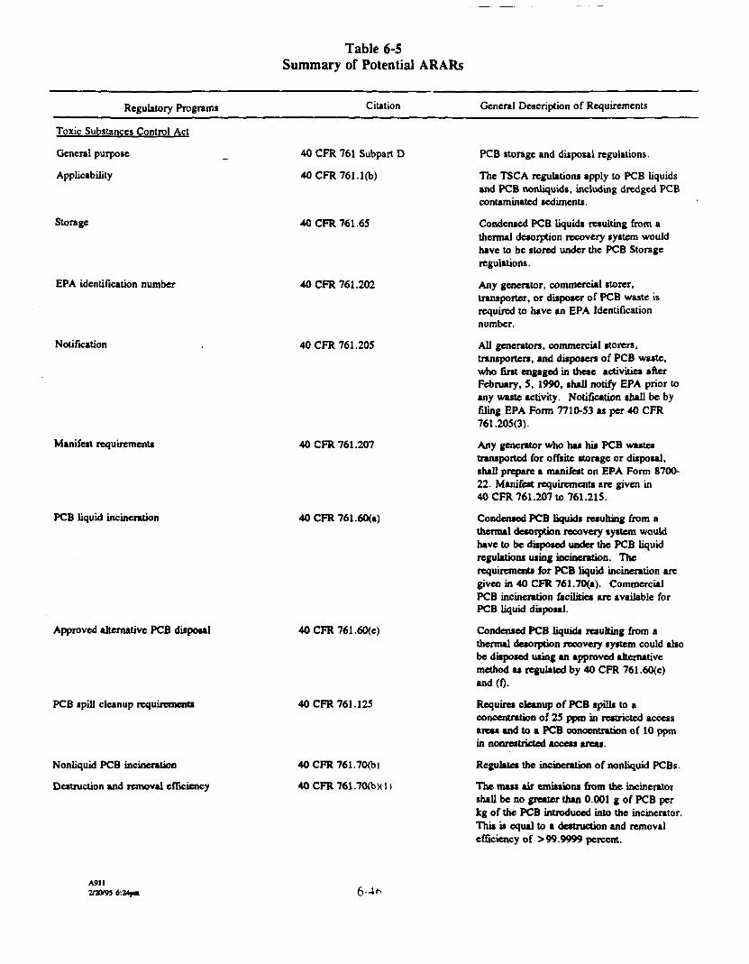
Table 6-5Summary of Potential ARARs
Regulatory Programs Citation General Description of Requirements
Toxic Substances Control Act
General purpose
Applicability
Storage
EPA identification number
Notification
40 CFR 761 Subpart D
40CFR761.1(b)
40 CFR 761.65
40 CFR 761.202
40 CFR 761.205
Manifest requirements 40 CFR 761.207
PCB liquid incineration 40CFR761.60(a)
Approved alternative PCB disposal 40CFR761.60(c)
PCB spill cleanup requirements
Nonliquid PCB incineration
Destruction and removal efficiency
40 CFR 761.125
40 CFR 761.70(b)
40 CFR 761.70<bMI)
PCB storage and disposal regulations.
The TSCA regulations apply to PCB liquidsand PCB nonliquids, including dredged PCBcontaminated sediments.
Condensed PCB liquids resulting from athennal desorption recovery system wouldhave to be stored under the PCB Storageregulations.
Any generator, commercial storer,transporter, or disposer of PCB waste isrequired to have an EPA Identificationnumber.
All generators, commercial storers,transporters, and disposers of PCB waste,who first engaged in these activities afterFebruary, 5, 1990, shall notify EPA prior toany waste activity. Notification shall be byfiling EPA Form 7710-53 as per 40 CFR761.205(3).
Any generator who has his PCB wastestransported for offsite storage or disposal,shall prepare a manifest on EPA Form 8700-22. Manifest requirements are given in40 CFR 761.207 to 761.215.
Condensed PCB liquids resulting from athennal desorption recovery system wouldhave to be disposed under the PCB liquidregulations using incineration. Therequirements for PCB liquid incineration aregiven in 40 CFR 761.70(a). CommercialPCB incineration facilities are available forPCB liquid disposal.
Condensed PCB liquids resulting from athennal desorption recovery system could alsobe disposed using an approved alternativemethod as regulated by 40 CFR 761.60(c)and(f).
Requires cleanup of PCB spills to aconcentration of 25 ppm in restricted accessareas and to a PCB concentration of 10 ppmin nonrestricted access areas.
Regulates the incineration of nonliquid PCBs.
The mass air emissions from the incineratorshall be no greater than 0.001 g of PCB perkg of the PCB introduced into the incinerator.This is equal to a destruction and removalefficiency of > 99.9999 percent.
A9112/3V9S 6:Z4f«

Table 6-5(continued)
Regulatory Programs Citation General Description of Requirements
Combustion efficiency
PCB flow rate monitoring/recording
Temperature monitoring
Continuous emission monitoring
Automatic waste feed cut-off
Hydrogen chloride removal
Low risk waiver
40CFR761.70(b)(2)[40CFR761.70(a)(2)]
40CFR761.70(b)(2)[40CFR761.70(a)(3)]
40CFR761.70(bX2)[40CFR761.70(aX4)]
40CFR761.70(b)(2)[40CFR761.70(aX7Xi)]
40CFR761.70(b)(2)[40CFR761.70(a)(8)(i)][40CFR761.7<HaX8)(ii)J
40 CFR 76L70(bX2)[40CFR761.70(aX9)J
40CFR761.70(dX5)
Incineration approval, trial burndetermination
PCB trial burn plan
40CFR761.70(d)
40CFR761.70(dX2)(ii)
The combustion efficiency of the incineratorshall be at least 99.9 percent as defined by40CFR761.70<a)(2).
The rate and quantity of PCBs fed to thecombustion system shall be measured andrecorded at regular intervals of no longer than15 minutes.
The temperature of the incinerator shall becontinuously measured and recorded usingeither direct or indirect readings.
A minimum, whenever the incinerator isprocessing PCBs, continuous monitoring andrecording shall be done for stack emissions ofoxygen, carbon monoxide, and carbondioxide.
The flow of PCB wastes to the incineratorshall stop automatically if the continuous stackemission monitor or the PCB feed ratemonitor should fail. An approvedcontingency plan with alternative measures ispossible.
Water scrubbers or an approved alternativemust be used for hydrogen chloride controlduring PCB incineration.
A waiver may possibly be obtained if one ormore of the requirements of 40 CFR761.70(a) or 761.70(b) are not met, but donot result in an unreasonable risk of injury tohealth or the environment from PCBs.
Approval of a PCB incinerator must beobtained with a written application, andpossibly a trial burn. The RegionalAdministrator will determine if a trial bum nrequired.
If a PCB trial burn is required, a detailed puuifor conducting and monitoring the trial burnmust be submitted.
Authorizes EPA to regulate the generationtransportation, treatment, storage, anddisposal of hazardous waste. RCRA perm**are not required for CERCLA actions takenentirely onsite. Administrative requirement*such as reporting and recordkeeping, arc r*«ARARs for onsite activities. However »n»»tractivities may need to meet other pertinentrequirements.
AMI6-47

Table 6-5(continued)
Regulatory Programs Citation General Description of Requirements
RCRA Generation Standards
RCRA Transportation Standards
RCRA General Standards
RCRA Preparedness and Prevention
RCRA Contingency Plan and EmergencyProcedures
RCRA Closure and Post-Closure
40 CFR 262
40CFR263
40 CFR 264.10-264.19
40 CFR 264.30 - 264.37
40 CFR 264.50-264.56
40 CFR 264.110 -264.120
RCRA Storage Standards 40 CFR 264
Hazardous Waste Incinerators 40 CFR 264, Subpart O
Hazardous Waste Miscellaneous Units 40 CFR 264, Subpart X
Specifies requirements for manifesting,pretransportation, record keep ing, andreporting.
Specifies requirements for approval of theRCRA transporter and the manifesting system.
Specifies requirements on general facilitystandards for waste analysis, securitymeasures, inspections, training, and locationstandards (100-year iloodplain).
Facility standards for safety equipment andspill control.
Facility standards for emergency planning andprocedures to be implemented followingspills, fires, explosions, damaging weatherevents, etc.
General standards for closure of hazardouswaste treatment and storage equipment.Requires minimization of need for futuremaintenance and control of hazardous waste,runoff, or decomposition products. Requiresdisposal or decontamination of equipment,structures, and soils.
If hazardous wastes are to be stored onsite,then the storage area shall comply with theregulations for containers (Subpart I), tanks(Subpart J), surface impoundments(Subpart K), or waste piles (Subpart L).
Establishes performance standards forhazardous waste incinerators for destructionand removal efficiency of 99.99 percent forprincipal organic hazardous compounds,paniculate emissions (0.08 g/dscf corrected to7 percent oxygen), and hydrogen chlorideemission rates or removal efficiency (4 Ib/hror 99 percent control). Also requires thatfugitive emissions be controlled and thatcertain process operating conditions bemonitored (e.g., combustion temperature,waste feed rate, indicator of combustion gasvelocity, carbon monoxide).
Establishes performance standards formiscellaneous hazardous waste treatment unitssuch as thermal desorption systems.
A9112/3W5 fc24pa 6-48

Table 6-5(continued)
Regulatory Programs Citation General Description of Requirements
Air Emission Standards for Tanks, SurfaceImpoundments, and Containers (Proposed)
40 CFR 264, Subpart CC40 CFR 264.1080
Potentially applicable. Will apply to unitswhich meet the definition of a tank, surfaceimpoundment, or container and which managehazardous waste with volatile organicconcentrations of 500 ppnv or more. Notapplicable for 90-day accumulation facilities.
Standards to control organic emissions
40 CFR 264.1086
40 CFR 266.104
Standards to control metals emissions 40 CFR 266.106
Standards to control hydrogenchloride and chlorinegas emissions
40 CFR 266.107
Boilers and Industrial Furnaces 40 CFR 266,
Under paragraph (b)(2), the control deviceshall operate at the conditions that reduce theorganics in the gas stream by 95 percent byweight.
Under paragraph (b), the stack gasconcentration of carbon monoxide (CO) froma boiler or industrial furnace burninghazardous waste cannot exceed 100 ppn\ onan hourly rolling average basis, continuouslycorrected to 7 percent oxygen, dry gas basis.(See regulation for alternative CO standard).
Under paragraph (d), for conforrnance toTier III metals controls, a site-specific riskassessment must be conducted demonstratingthat applicable ambient levels of metals arenot exceeded. This is accomplished bymeasuring metals emission rates andconducting site-specific dispersion analyses.The acceptable ambient air levels are given asreference air concentrations in Appendix IVand as risk specific doses in Appendix V ofPart 266.
Under paragraph (d), for conforrnance toTier III controls, a site-specific riskassessment must be conducted bydemonstrating that acceptable ambient levelsof hydrogen chloride and chlorine are notexceeded. This is accomplished by measuringhydrogen chloride and chlorine emission ratesand conducting a site-specific dispersionanalyses. The acceptable ambient air levelsare given as reference air concentrations inAppendix IV of Part 266.
Subpart H Establishes rules for the control oforganic emissions, paniculate matter, metalsemissions, and hydrogen chloride and chlorineemissions from boilers and industrial furnacesburning hazardous wastes. (Boiler andindustrial furnace standards for metals,chlorine, and hydrogen chloride are applicableto hazardous waste incinerators).
A9112/20T95 6:24pm 6-49

Table 6-5(continued)
Regulatory Programs Citation General Description of Requirements
RCRA Land Disposal Restrictions _ 40 CFR 268 If hazardous wastes are shipped offsite forland disposal, a determination must be madeas to whether the waste does or docs not meetspecified treatment standards for landdisposal. Notification and certification formsmust accompany all offsite waste shipments,documenting whether the waste meets landdisposal restrictions or whether furthertreatment is required for the waste to meetland disposal restrictions.
A waiver from the federal land disposalrestrictions can be applied for under Section!21(dX4)ofCERCLA. IftheCERCLAwaiver is not applicable, then all land disposalrestrictions are applicable per the federalregulations.
Permit Program 40 CFR 270, Subpart C Identifies conditions and information requiredin all permits.
Permit Program (Additional Conditions)
Permit Program (Omnibus Provision)
40 CFR 270.30
40 CFR 270.32
Hazardous Waste Incinerator Guidance Series:
Identifies additional conditions, as required ona case-by-case basis, for all permits.
Paragraph (bX2) established the "omnibuspermitting authority" by stating that the EPAAdministrator or the State Director shallinclude terms and condition* as necessary toprotect human health and the environment.
Volume 1 - Guidance Manual for HazardousWaste Incinerator Permits, Mitre Corp.,1983, NTIS jCPB-84-100577.
Volume 2 - Guidance on Setting PermitCondition and Reporting Trial Burn Results,EPA/625/6-89/019. Acurex, 1989.
Volume 3 - Hazardous Waste IncineratorMeasurement Guidance Manual, MRI, 1989.
Volume 4 - Guidance on Metal(s) andHydrogen Chloride Controls for HazardousWaste Incinerators, 1989.
Volume 5 - Guidance on PIC Controls forHazardous Waste Incinerators, 1989.
Volume 6 - Proposed Methods forMeasurements for Carbon Monoxide, Oxygen,Total Hydrocarbons, Hydrogen Chloride, andMetals at Hazardous Waste Incinerators,MRI, September, 1988.
A911 6-50

Table 6-5(continued)
Regulatory Programs Citation General Description of Requirements
Clean Air Act
National Ambient Air QualityStandards
New Source Review/Prevention of SignificantDeterioration
40 CFR 50
40 CFR 51.166 & 52.21
Nonattainmcnt Area 40 CFR 51 and 52(Sec. 172 of CAA)
New Source Performance Standards
National Emission Standards forHazardous Air Pollutants (NESHAPs)
40 CFR 60, Subpart A
40 CFR 61
National Emission Standard Cor Equipment Leaks(Fugitive Emission Source)
40 CFR 61, Subp.it V
40 CFR 61.24040 CFR 61.240
Establishes maximum allowable ambient airconcentration for criteria pollutants PMIO,SO2, carbon monoxide, NO,, O,, and lead).No new construction or modification may emitan amount of any criteria pollutant that willinterfere with attainment of the NationalAmbient Air Quality Standards.
Applies in attainment or unclassifiable areas.Designed to maintain good air quality withsome allowances for economic growth. Newand modified sources which exceed emissionrate thresholds are required to obtain aprcconitruction permit. Cannot exceedmaximum allowable increase (increment) inambient air quality. Must comply with NewSource Performance Standards and NESHAPsand use best available control technology.May need to demonstrate that emissions willbe below threshold amounts (i.e., possiblythrough submission of a source air permitapplication).
Not applicable. Applies to new or modifiedmajor sources in nonattainment areas. Majorsource thresholds for nonattainment areasrange from 10 to 100 TPY depending on thedegree of nonattainment. Requires existingmajor sources to apply reasonably availablecontrol technology to reduce VOC emissions.
Existing risk-based standards apply to certaincategories of facilities emitting 7 hazardousair pollutants (arsenic, asbestos, benzene,beryllium, mercury, radionuclkJe*. or vinylchloride). Also lists 25 substances thatinclude consideration of serious health effects,including cancer from ambient air exposure tothe substance. NESHAPi have not beenestablished for hazardous waste incinerators;however, standards for existing sourcecategories could potentially be applied to thesite remediation process.
Applies to sources that are intended to operatein volatile hazardous air pollutant service:pumps, compressors, pressure relief devices,sampling connections, systems, open-endedvalves or lines, valves, flanges and otherconnectors, product accumulator vessels, andcontrol devices or systems required by thissubpart.
AMI2/20*5 6:24pm

Table 6-5(continued)
Regulatory Programs Citation General Description of Requirements
40 CFR 61.242-11
State APC
National Ambient Air Quality Standards, NewSource Review/Prevention of SignificantDeterioration, New Source PerformanceStandards, NESHAPs
APC Rules
- Visible Emissions
- Fugitive Dust and FugitiveEmissions
See above citations.
Ohio Administrative Code (OAC)3745-17-07, A-D
OAC 3745-17-08Al, A2, B, D
- "Air Toxics Emissions Guidelines" OAC 3745-17-09; A, B, C
U.S. Department of TransportationHazardous Material Regulations
Regulates transportation of hazardous materials 49 CFR 171-179
Under paragraph (c), enclosed combustiondevices shall reduce the volatile hazardous airpollutant emissions by 95 percent or greater,or provide a minimum residence time of0.5 seconds at a minimum temperature of760«C(1,400*F).
State regulations are essentially the same asfederal regulations.
Establishes emission opacity restrictions(20 percent or 40 percent, depending on timeinterval) for stationary sources.
Requires that precautions be taken to preventpaniculate emissions from becoming airbornewhile materials are being handled,transported, or stored. Includes visiblerestrictions beyond lot line and provisions forrequiring control if the emissions cause anuisance.
Program is based on general regulationprohibiting air pollution. Informal guidelineshave been developed based on using AmericanConference of Governmental IndustrialHygienists threshold limit values to estimatean acceptable ambient air concentration.
If hazardous wastes are shipped offsite andmaterials manifested, then transportation ofthe hazardous waste is regulated by the U SDepartment of Transportation. Theseregulations include general requirements(49 CFR 171); shipping papers, marking, »mllabeling (49 CFR 172); general shippingrequirements (49 CFR 173); and shippingrequirements via motor carriers (49 CFR177). For ORM-E classified hazardou*materials, the motor carrier must prcvem thedischarge of material to the environment
A9116-52

Table 6-5(continued)
Regulatory Programs Citation General Description of Requirements
Endangered Species Act
Protection of Endangered Species 16 USC 1531
Fish and Wildlife Coordination Act
Proposed actions shall reflect the consideration ofeffects on fish and wildlife
Protection of Wetlands Executive Order 11990
Floodplain Manager Executive Order 19988
National Pollution Discharge Elimination System(NPDES) Standard and Storm Water Rule
40CFR122
Occupational Safety and Health Act
Recordkeeping, Reporting, and RelatedRegulations
29 CFR 1904
29 CFR 1910, Subpart A29 CFR 1910, Subpart B
Statute provides a means for protectingendangered species. EPA must ensure thatthe actions that they authorize are not likely tojeopardize the continued existence ofendangered or threatened species, or adverselymodify or destroy their critical habitats(Section 7(a)).
Planners shall consider the effects theremedial activities will have on fish andwildlife. The U.S. Fish and Wildlife Serviceshall be consulted prior to remediation.
Requires consideration during remedialactions that may affect known wetlands.Authorizes the Army Corps of Engineers totake action to minimize destruction, loss, ordegradation of wetlands, and to preserve andenhance the natural and beneficial values ofwetlands.
Actions must be taken to reduce the risk offlood loss; to minimize the impact of floodson human safety, health, and welfare; and torestore and preserve the natural and beneficialvalues served by floodplains.
Actions must be taken to reduce the release ofhazardous wastes to POTWi in order tomaximize human safety, health, and welfare.The provision specifies releases that can occurfrom industrial discharges and from stormwater runoff. Water quality criteria arespecified for PCBs as guidelines for thedevelopment of water quality standards forsurface waters by the State, taking intoaccount physical, chemical, biological, andeconomic factors.
Regulations for recordkeeping and reportingof compliance with safety conditions duringmanagement of hazardous wastes.
GeneralAdoption and Extension of EstablishedFederal Standards
A9112/3V95 6:24p« 6-53

Table 6-5(continued)
Regulatory Programs Citation General Description of Requirements
29 CFR 1910, Subpart C29 CFR 1910, Subpart D29 CFR 1910, Subpart E29 CFR 1910, Subpart F
29 CFR 1910, Subpart G
29 CFR 1910, Subpart H29 CFR 1910, Subpart I29 CFR 1910, Subpart J29 CFR 1910, Subpart K29 CFR 1910, Subpart L29 CFR 1910, Subpart M
29 CFR 1910, Subpart N29 CFR 1910, Subpart O29 CFR 1910, Subpart P
29 CFR 1910, Subpart Q29 CFR 1910, Subpait S29 CFR 1910, Subpart Z
General Safety and Health ProvisionsWalking-Working SurfacesMeans of EgressPowered Platforms, Mantifts, and Vehicle-Mounted Work PlatformsOccupational Health and EnvironmentalControlHazardous Materials (See below)Personal Protective EquipmentGeneral Environmental ControlsMedical and First AidFire ProtectionCompressed Gas and Compressed AirEquipmentMaterials Handling and StorageMachinery and Machine GuardingHand and Portable Powered Tools and OtherHand-Held EquipmentWelding, Cutting and BrazingElectricalToxic and Hazardous Substances (See below)
Hazardous Watte Operations Standard 29 CFR 1910, Subpart I
Toxic and Hazardous Substances
Site Remediation Safety Specifications
19 CFR 1910, Subpart Z
Log and Summary of Occupational Injuries and 29 CFR 1914Illnesses
29 CFR 1926
Covers hazardous substance responseoperations at Superfund sites. Air monitoringmust be used to identity and quantify airbornelevels of hazardous substances and healthhazards to determine the appropriate level ofpersonal protective equipment. Workers arerequired to have 40 hours of training and an8-hour annual refresher. Supervisors arerequired to have 8 hours of training. Visitorsto the site are also required to have training.
Establishes limits for employee exposure toair contaminants in the workplace. Includesrequirements for engineering controls (such aslocal exhaust systems) and personal protectivedevices. Standards have been established for26 substances. (The American Conference ofGovernment and Industrial HygienisU hasestablished threshold limit values as guidelinesfor a large number of other substances.)
Recording and reporting occupational injuriesand illnesses.
Specifies the type of safety equipment andprocedures to be followed during siteremediation.
A9116-54

Table 6-5(continued)
Regulatory Programs Citation General Description of Requirements
Suoerfiind Amendments and Reauthnj-jfl'tinn
CERCLA
- Cleanup Standards
SARA Title I
40 CFR 121(d)(l)
- Remedial Action Selection
Emergency Planning andCommunity Right-to-Know Act
EPA Designated, ReportableQuantities and Notification Requirementsfor Hazardous Substances
40 CFR 121(d)4)
SARA Title HI
40 CFR 302.6
Requires EPA to apply cleanup standards toSuperfund sites that are at least as stringent asARARs. Air quality ARARs could includeany of the federal regulations listed above orany state regulations.
A remedial action may be selected which doesnot meet ARARs if specific circumstances orconditions exist.
Regulations associated primarily withnotifying public of hazardous and toxicmaterials that are managed at a facility.
A facility shall report any release of ahazardous substance in quantity equal to orexceeding the reportable quantity to theNational Response Center.
Emergency Planning andNotification
Emergency Planning andNotification
- Toxic Chemical Release Reporting
40 CFR 355.30
40 CFR 355.40
40 CFR 372
Ohio APC Rules
Air Emissions from Hazardous WasteFacilities
OAC 3734.02
A facility shall notify the emergency planningagency of any extremely hazardous substanceequal to or greater than the threshold planningquantity.
A facility shall notify emergency responsepersonnel of an offske release of a reportablequantity of any extremely hazardous substanceor CERCLA hazardous substance.
Requires certain facilities to submit annualreports that account for almost all releases,emissions, and disposal of toxic chemicalsduring a calendar year. Regulated facilitiesinclude those which fall in SIC Codes 20-39,have 10 or more employees, and manufacture,process, or otherwise use one or more of 330listed chemicals above threshold quantities.
No hazardous waste facility shall emit anypaniculate matter, dust, fumes, gas, mist,smoke, vapor, or odorous substance thatinterferes with the comfortable enjoyment oflife or property or is injurious to publichealth.
AMI6-55

Table 6-5(continued)
Regulatory Programs Citation General Description of Requirements
Hazardous Waste Facility EnvironmentalImpact -
OAC 3734.05
Hazardous Waste Facility Minimum Risk OAC 3734.05
Approval of Plans for Disposal of Wastes OAC 6111.45
Air Pollution Nuisances Prohibited OAC 3745-15-07 (A)
Stack Height Requirements OAC 7745-16-02 (B, C)
Paniculate Ambient Air Quality Standards OAC 3745-17-02 (A, B, C)
Particulatc Non-Degradation Policy
Visible Paniculate Emissions Control
Emission Restrictions for Fugitive Dust
OAC 3145-05
OAC 3745-07(A, B, C, & D)
OAC 3745-08(Al, A2, B, D)
Incinerator Paniculate Emission and Odor OAC 3745-09 (A, B. C)Restrictions
Ambient Air Quality Standards for Carbon OAC 3745-21-02 (A. B. C)Oxides
Carbon Oxides Non-Degradation Policy OAC 3745-21-05
A hazardous waste facility installation andoperation permit shall not be approved unlessit proves that the facility represents theminimum adverse environmental impact,considering the state of available technology,the nature and economics of variousalternatives, and other pertinentconsiderations.
A hazardous waste facility installation andoperation permit shall not be approved unlessit proves that the facility represents theminimum risk of all of the following:
The disposal of industrial waste is prohibitedwithout prior approval by the director of OhioEPA.
Defines air pollution nuisance as the emissionor escape into the air from any source(s) ofsmoke, ashes, dust, dirt, grime, acids, fumes,gases, vapors, odors, and combination! of theabove that endanger health, safety, or welfareof the public or cause personal injury orproperty damage. Such nuisances areprohibited.
Establishes allowable stack height for aircontaminant sources based on goodengineering practice.
Establishes specific standards for totalsuspended paniculate*.
Degradation of air quality in any area whereair quality is better than required byOAC 3745-17-02 is prohibited.
Specifies the allowable opacity for paniculateemissions; provides exceptions foruncombined water, start-up/shutdown of fuelburning equipment, and malfunctions.
All emissions of fugitive dust shall becontrolled.
Establishes paniculate emission limitationsand design-operation requirements to preventthe emission of objectionable odor.
Establishes specific air quality standards forcarbon oxides, carbon monoxide, ozone, andnon-methane hydrocarbons.
Prohibits significant and avoidabledeterioration of air quality.
A9112/21W5 6:34f« 6-56

Table 6-5(continued)
Regulatory Programs Citation General Description of Requirements
Organic Material Emission ControlStationary Source ~
Carbon Monoxide Emission ControlStationary Source
OAC 3745-07 (A-E)
OAC 3747-08 (A-E)
Water/Air Permit Criteria for Decision by the OAC 3745-31-05Director
Permit Information Required for all Hazardous OAC 3745-50-44Waste Facilities
Additional Permit Information: HazardousWaste Storage in Containers
OAC 3745-5O44 (Cl)
Additional Permit Information: HazardousWaste Treatment by Incineration
OAC 3745-50-44 <C8)
Additional Permit Information: Hazardous OAC 3745-50-44 (C9)Waste Treatment/Storage/Disposal inMiscellaneous Units
Hazardous Waste Facility Permit
Trial Burn for Incinerators
OAC 3745-50-7 (p. 16)
OAC 3745-50-7 (p. 16)
Requires control of emissions of organicmaterials from stationary sources. Requiresbest available control technology.
Requires any stationary source of carbonmonoxide to minimize emissions by the use ofbest available control technologies andoperating practices in accordance with bestcurrent technology.
A permit to install or plans must demonstratebest available technology and shall notinterfere with or prevent the attainment ormaintenance of applicable ambient air qualitystandards.
Establishes the substantive hazardous wastepermit requirements necessary for Ohio ERAto determine facility compliance. Includesinformation such as facility description, wastecharacteristics, equipment descriptions,contingency plan, facility location,topographic map, etc.
Established substantive hazardous wastepermit requirements necessary for Ohio EPAto determine adequacy of container storage.Includes information such as description ofcontainment system, detailed drawings, etc.See OAC 3745-55-70 through 3745-55-78 foradditional container requirement!.
Establishes substantive hazardous waste permitrequirements necessary for Ohio EPA todetermine adequacy of waste piles used totreat or store hazardous waste. Includesinformation such as waste characteristics,detailed design plans and reports, control ofrun-on and runoff, closure information, etcSee OAC 3745-56-50 through 3745-56-60 foradditional waste pile requirements.
Establishes substantive hazardous wasterequirements necessary for Ohio EPA todetermine adequacy of waste piles used 10treat or store hazardous waste. Includesinformation such as waste characteristic*,detailed design plans and reports, control ofrun-on and runoff, closure information, etc
Establishes general permit conditionsto all hazardous waste facilities in OhioIncludes conditions such as operation andmaintenance, site access, monitoring, etc
Specifies requirements of a trial burn
A9112/2*95 6-57

Table 6-5(continued)
Regulatory Programs Citation General Description of Requirements
General Analysis of Hazardous Waste
Security for Hazardous Waste Facilities
OAC 3745-54-13
OAC 3745-54-14 (A, B, C)
Inspection Requirements for Hazardous Waste OAC 3745-54-15Facilities
Content of Contingency Plan: HazardousWaste Facilities
OAC 3745-54-52 (A-F)
Amendment of Contingency Plan: Hazardous OAC 3745-54-54 (A)Waste Facilities
Emergency Procedures: Hazardous WasteFacilities
Disposal/Decon of Equipment Structuresand Soils
Waste Analysis for Incinerators
OAC 3745-54-55
OAC 3745-55-14
OAC 3745-57-41 (A, B)
Principal Organic Hazardous Constituents; OAC 3745-59-42 (A-C)Incinerators
Performance Standards for Incinerators
Incinerator Trial Bum Alternative Data
OAC 3745-57-43 (A-C)
OAC 3745-54-45 (A-F)
Monitoring and Inspection of Incinerators OAC 3745-57-47 (A-C)
Prior to any treatment, storage, or disposal ofhazardous wastes, a representative sample ofthe waste must be chemically and physicallyanalyzed.
Hazardous waste facilities must be secured sothat unauthorized and unknown entry areminimized or prohibited.
Hazardous waste facilities must be inspectedregularly to detect malfunctions,deteriorations, operational errors, anddischarges. Any malfunctions ordeteriorations detected shall be remediedexpeditious ly.
Hazardous Waste Facilities must have acontingency plan that addresses any unplannedrelease of hazardous wastes or hazardousconstituents into the air, soil, or surfacewater. This rule establishes the minimumrequired information of such a plan.
The contingency plan must be amended if itfails in an emergency, the facility changes (indesign, construction, maintenance oroperation), the list of emergency coordinatorschanges or the list of emergency equipmentchanges.
At all times, there should be at least oneemployee either on the premises or on call tocoordinate all emergency response measures.
Requires that all contaminated equipment,structures, and soils be properly disposed ofor decontaminated. Removal of hazardouswastes or constituents from a unit mayconstitute generation of hazardous wastes.
Requires that waste analysis be performed fortrial bum and for normal operation ofincinerator.
Establishes method by which principal organichazardous constituents will be specified.
Specifies performance standards that allincinerators must meet (destruction removalefficiencies, hydrogen chloride emissions,paniculate emissions).
Specifies general operating requirements forall incinerators.
Requires the monitoring of certain parameterson a continuous basis and inspections ofequipment.
A9112/300$ 6:2*0 6-58

Table 6-5(continued)
Regulatory Programs Citation General Description of Requirements
Closure of Incinerators
Environmental Performance Standards forMiscellaneous Units
OAC 3745-57-51
OAC 3745-57-91 (A-C)
Monitoring, Inspections, Analyzing, Response, OAC 3745-57-92Reporting, and Corrective Action forMiscellaneous Units
Post-Closure Care for Miscellaneous Disposal OAC 3745-57-93Units
Requires that all hazardous waste andhazardous waste residues be removed form theincinerator site.
Establishes location, design, construction,operation, maintenance, and closurerequirements for miscellaneous units used totreat, store, or dispose of hazardous wastes.
Requires that monitoring, analysis, inspection,response, reporting, and corrective action beconducted as necessary at miscellaneous unitsto ensure that human health and theenvironment are protected.
Requires post-closure care of miscellaneousunits that are disposal units and of treatmentor storage miscellaneous units that leavecontaminated soils or groundwater afterclosure.
A911200/95 6:24pm 6-59

Table 6-6Format for Permit Applications for PCB Incinerators
Section _ Contentsi. Permit Application Cover
ii. Table of ContentsI.0 Summary2.0 Project Organization3.0 Waste Description4.0 Process Engineering Description5.0 Monitoring Plan6.0 Monitoring Procedures7.0 Data Reporting/Recordkeeping8.0 Inspection Procedures9.0 Spill Prevention Control and Countermeasures Plan10.0 Safety PlanII.0 Training Plan12.0 Plans for a Demonstration (Trial Burn)'13.0 Test Data or Engineering Performance Calculations14.0 Other Permits/Approvals15.0 Schedule of Pre-Operation Events16.0 Quality Assurance Plan17.0 Standard Operating Procedures18.0________________Closure Plan________________________
•For a research and development permit, this section would present the planned research activities.
A9112/20/05 6:24pm 6"60

Table 6-7Format for the Demonstration Test Report
Section _ Contentsi. Report Coverii. Table of Contents
iii. Certification Letter1.0 Summary2,0 Process Operation3.0 Sampling and Monitoring Procedures4.0 Analytical Procedures
5.0 Test Results6.0 Quality Assurance Summary7.0 Visits and Audits8.0 Closure
9.0 Waste Disposal Manifests
Appendices
2/3CV93 6:2*pm 6-61

Table 6-8Performance Criteria for Thermally Treated Sediments
AnalyticalParameters
PCBsTotal PCBs (Method 8080)
Volatiles
1,1-Dichloroethene1,1,1 -Trichloroethane1 , 1 ,2-TrichIoroethane1 , 1 ,2,2-Tetrachloroethane1,2-DichIoroethene (total)BenzeneChlorobenzeneChloroformEthylbenzeneMethylene chlorideTetrachloroetheneTolueneTrichloroethene
Vinyl chloride
Semivolatiles1 ,2-Dichlorobenzene1 ,4-DichlorobenzeneNaphthalene
•Source: EPA 1986c.
A9112/30/95 6:24pn
Organic'Carbon-Water
Partition Coefficient(K^, mL/g)
Varies
6515256
11859/49
83
330
311,100
35364300126
57
1,700
1,700
1,400
6-<s:
ResidentialCleanup Goal
(Performance Criteria)(mg/kg)
1.3
17393,451
17951
2,5005087
1,672437,167
1,360196
874,335927
5
393,451425
174,867

Table 6-9Proposed Operating and Performance Requirements
Parameter MeasurementDestructive"'Type APC
Recovery0"Type APC
POHC DRE
PCBDRE
Afterburner temperature
Afterburner residence time
Offgas oxygen
Combustion efficiency
Stack HC1/C12 emissions
Stack metal emissions
Stack participate emissions
Stack CO concentration
Stack dioxins/furans
Stack semivolatile organics
Stack volatile organics
Stack nitrogen oxides concentration
Dry participate device (baghouse)
Recovery system efficiency fortotal contaminants of concern
Trial burn feed/stack sampling
Trial burn feed/stack sampling
60-minute rolling average
Stack flow 60-minute rolling average
CEMS 60-minute rolling average
CEMS 60-minute rolling average
Trial burn feed/stack sampling
Trial burn feed/stack sampling
(Corrected to 7% Oj) Trial burnstack sampling
(Dry basis, corrected to 1% QJCEMS 60-minute rolling average
Operating temperature
Trial burn feed/stack sampling
>99.99
> 99.9999
(c)
> 2 seconds
99.9%
(d)
(d)
0.08 g/dscf
100 ppmv
(e)
(0(f)(g)
<450°F
NA
NA
NA
NA
NA
NA
NA
(d)
(d)
0.08 g/dscf
NA
(e)
(0
(0NA
<450°F
95% «'
(a) Includes an afterburner.(b) Pfaysical/chemical treatment including condensers, wet scrubbers, carbon adsorption, or other unit operations.(c) Contractor specific.(d) Limits to be determined.(e) Sample and analyze to determine 10 highest peaks.(f) Monitor only, no performance requirement.(g) Per 40 CFR 264.1086 (b)(2).
A91I2/3V93 6:24pm 6-63
7.0 PRELIMINARY DESIGN FOR SOLIDIFICATION
Solidification is required for designated untreated contaminated sediments from Fields Brook.This section discusses the solidification process, previous engineering studies, description of themajor processes and equipment, the contingency plan, and the operation and maintenance plan.The anticipated volumes of sediments to be treated by solidification are presented in Table 2-2.The major processes, and the type of equipment that will be required to perform these processesare discussed in Section 7.1.3. Contingencies are identified, and solutions for these contingenciesare presented in Section 7.1.4. The solidification process does not require an operation andmaintenance plan except for the day-to-day operation of this treatment process, which will have arelatively short life. Solidification of the contaminated material will be accomplished using acombination of in situ and bulk mixing, and the final product will be required to meet the designcriteria established in Section 7.2.
7.1 DESCRIPTION OF REMEDY
Solidification treatment is defined as a process that results in a solid mass of material that hashigh structural integrity. The contaminated sediments identified to be solidified will be mixedwith an agent(s) to form a free-standing material with no free liquid. The agents generally usedinclude fly ash, kiln lime dust, Portland cement, potassium silicate, and sodium silicate, whichare mixed with sediments either in pug mills or in situ, using mixing machines. The solidifiedmaterial will then be placed in the landfill and compacted.
7.1.1 Engineering Studies
The SLDI report discusses the bench-scale testing that was performed on contaminated sedimentsfrom the site. Section 3.4, Solidification Design Investigation, summarizes the results andconclusions about the solidification design mixes that were tested.
A9112/20/95 6:34pm 7-1
Total waste analyses and the TCLP are discussed in the SLDI report. The sediments wereclassified as silty sand and silt with unit weights ranging from 103 to 112 Ib/ft3. In Phase 1 of
the bench-scale testing, various mix designs were used, and the solidified sediments were testedfor unconfmed compressive strength and free liquid and using the TCLP. In Phase 2, thepurpose was to optimize the mix design using two reagents based on the Phase 1 results. Phase 2testing included leachability using modified American National Standards Institute (ANSI) Method16.1, unconfmed strength, bulking, and cost for solidifying.
7.1.2 Mass Balance and Flow Diagrams
An overall process flow diagram is shown in Figure 2-15. There are no specific flow diagramsfor the solidification process. Table 2-2 summarizes the estimated sediment and water volumesfrom each reach requiring treatment. The table breaks down these volumes by the type oftreatment, based on the SLDI report.
7.1.3 M^jor Processes and Equipment
The solidification process includes two alternatives, in situ or bulk mixing (using the selected mixdesign) of the solidification agent(s) with the contaminated sediments. The contractor will beresponsible for developing the mix design and ensuring that the treated material meets the designcriteria. A combination of in situ and bulk mixing is proposed, based on the physical attributesof each exposure unit and the type of material that will be encountered during excavation of theexposure units. A performance-based approach will be used to the maximum extent practical,and many of the actual details will be left to the remedial action contractor to define or adjustbased on field conditions and the special knowledge of the contractor.
In Situ Mixing
In situ mixing of the solidification agent(s) with the sediment can be accomplished by spreadingthe agent over the area to be excavated and mixing it using conventional equipment, or by direct
A9116:34pm 7-2

injection and mixing with the injector head. In situ mixing of a solidification agent could be used
as a pretreatment step to absorb water from the sediments in certain areas and to make thematerial handling process easier by eliminating a dewatering step. In situ mixing of thesolidification agent(s) will depend on the contractor; contractors specializing in the
solidification/stabilization process have their own specially designed equipment.
Bulk Mixing
Bulk mixing involves the use of a mobile pug mill and associated material handling equipment,specifically screens for separating materials, conveyors for moving the sediments and mixingagents, and weight batching system. The sediments would be stockpiled at the treatment facilityarea for processing. A front-end loader would be used to move the sediments from the stockpileto hoppers. The sediments would be screened to separate out large material greater than 2 in.,which would move to feed bins either by a loader or conveyor system. The material would exitthe feed bin via a conveyor belt system and move to a pug mill where the various reagents wouldbe added and mixed with the waste material. The end product would be transferred by dumptrucks to a stockpile area onsite.
Design Mix
The contractor will collect sediment samples having contaminant concentrations and physicalcharacteristics of sediment expected to be solidified with each formulation during full-scaleremedial action activities. The contractor will select a design mix for solidifying the sediment sothat (1) it meets the strength and leachability criteria, (2) the mobility and toxicity of theconstituents of concern are reduced, and (3) the long-term physical and chemical durability of thesolidified material can be determined before the sediment is landfilled. The contractor willdevelop a process control plan after the design mix has been selected and reviewed.
The contractor will perform the bench-scale treatability study to demonstrate that the solidifiedsediments will pass ANSI 16.1 and the design criteria listed in Section 7.2 and will have an
A9112/3V93 6:Mpn 7-3

effective unconfned compressive strength of 50 psi. The contractor will perform sufficienttesting to ensure that the mix will meet the solidification criteria.
The contractor will analyze the results for the design mix with those in the SLDI report and willoptimize the operation, output, and quality of the solidified sediment so that there is a 95 percentconfidence level that it will meet the aforementioned criteria. A hypothesis testing can beperformed using parameters that indicate the level of confidence that a proportion or percentile ofthe solidified sediment will meet the specified criteria. To develop the confidence level, thecontractor will refer to the attachment "Development of Confidence Removal Goals for FieldsBrook Sediment Excavation Cutline Delineation" in the Phase II SQDI Sampling Design - FieldSampling Plan Addendum 1. By optimizing the operation and quality, the contractor should nothave to sample the solidified sediment during full-scale operation because of the establishedconfidence level.
7.1.4 Contingency Plan
Contingency planning for solidification will identify those elements of the design or the operatingprocedures that pose a risk to human health or the environment if an accident, failure, or similaremergency episode occurs. Once identified, each element will have a predetermined responseaction to minimize any health or environmental impacts from the emergency event. Solidificationwill involve several operations that could experience failures or emergency episodes. Table 7-1summarizes the contingency plans for solidification of the sediments.
7.1.5 Operation and Maintenance Plan
The contractor will prepare an operation and maintenance plan for the solidification process inaccordance with the guidelines provided in the contract scope of work. At a minimum, the planmust address operating procedures for handling the contaminated material, treatment, airmonitoring, exclusion zones, and transporting the treated material.
A9112/20/95 6:Mf«i 7 -4

7.2 DESIGN CRITERIA
The following sections present the specific design criteria for the solidification of sediments fromthe contaminated reaches of Fields Brook. The sections include a summary of ARARs, permitsrequired for implementation of the solidification process, specific performance requirements forsystems or equipment to be provided by the contractor, and criteria for performing thesolidification.
7.2.1 ARARs
The nonbinding ARARs for the design were determined in the ROD, which was issued beforeSARA was enacted. Without waiving any rights or defenses, the FBPRPO believes that certainsubsequent federal and state regulations outline the appropriate technical requirements for certainaspects of the remedial action. For example, the RCRA and PCB incineration regulationsgenerally provide the appropriate requirements for onsite incineration. Therefore, the potentialARARs identified in this report for general consideration in the design process includeregulations promulgated since the issuance of the ROD.
Potential ARARs considered for the siting, design, construction, and operation of thesolidification process is summarized as follows.
Occupational Safety and Health Regulations (29 CFR 1910 and 1926)
OSHA has promulgated a comprehensive set of occupational safety and health standards. Theseregulations take a two-pronged approach to worker safety by establishing safe working practicesand safe levels of exposure to a variety of materials. These regulations will apply during theremedial activities.
-76:34fm /

Ohio Hazardous Waste Generator Standards (OAC Title 3745, Chapter 52)
These regulations specify standards for owners/operators of facilities where hazardous waste isgenerated. These requirements include standards for the identification of hazardous waste, thestorage of hazardous waste, the need to manifest waste shipped offsite, and pretransportrequirements.
Ohio Hazardous Waste Management (OAC Title 3745, Chapter 55)
These regulations regulate the treatment and storage of hazardous waste. If hazardous waste isstored onsite, it must be stored in compliance with the regulations for containers, tanks, surfaceimpoundments, or waste piles. These regulations also specify the design and operating standardsthat must be met for the treatment of hazardous waste.
Ohio Land Disposal Restrictions (OAC Title 3745, Chapter 59)
Because the Fields Brook ROD was signed before the enactment of SARA, the ARARs definedin the 1985 NCP apply to the site. Those ARARs are used as general guides in determining theextent of the remedial action (50 Federal Register 47917). They are much more flexible in theirapplication and are, in effect, nonbinding. Furthermore, when EPA promulgated the treatmentstandards for land disposal restrictions, EPA recognized that treatment of waste, includingcontaminated soils, to the treatment standards would not always be possible or appropriate(Superfund Publication 9347.3-06FS, September 1990). Therefore, the application of the landdisposal restrictions to soils and sediments at this site is not required.
RCRA Hazardous Waste Generation Regulations (40 CFR 262)
Part 262 describes the regulatory requirements imposed on generators of hazardous waste. Theregulations address accumulation wastes without a permit, preparing waste for shipment, and
1 £i2/20/95 6:34pm 7-O

using the uniform hazardous waste manifest system. Obviously, each generator must also befamiliar with the contents of Part 261, which explains how to identify a hazardous waste.
RCRA Standards for Owners/Operators of Hazardous Waste Treatment Storage, andDisposal Facilities (40 CFR 264)
The Part 264 standards impose stringent requirements on hazardous waste TSDFs; the regulationsfall into two general classifications: (1) Subparts A through H are general standards applicable toTSDFs, and (2) Subparts I through BB apply to specific types of treatment, storage, and disposalactivities (i.e., the use of landfills, incinerators, tanks) or specific equipment (e.g., drip pads andprocess vents).
Subpart O addresses the facility standards for incinerators, specifically how an incinerator is to bedesigned, constructed, operated, and maintained. Hazardous waste incinerators must complywith strict testing and performance standards.
Clear Air Act, National Primary and Secondary Ambient Air Quality Standards(40 CFR 50)
The NAAQS specify the maximum concentration of a federally regulated air pollutant in an arearesulting from all sources of that pollutant. No new construction or modification of a facility,structure, or installation may emit an amount of any criteria pollutant that will interfere with theattainment or maintenance of an NAAQS.
Clean Air Act, National Emission Standards for Hazardous Air Pollutants (40 CFR 61)
These standards regulate eight hazardous air pollutants [40 CFR 61.01 (a)] and list other airpollutants that cause serious health effects [40 CFR 61.01(b)]. These requirements could beapplicable if the thermal treatment results in the release of hazardous air pollutants.
T T2^0/95 6:34pm 7-7

Nonattainment Area Regulations (OAC 3745-31, 35)
These regulations require new or modified sources located in nonattainment areas to meet specialtechnology-based and air-quality-based requirements in addition to New Source PerformanceStandards. These requirements are referred to as Lowest Achievable Emission Rate and offsets.These regulations are potentially applicable because the Fields Brook site is in a nonattainmentarea for ozone.
Local (County) Regulations
Local and county statutes, regulations, and ordinances are preempted for onsite remedial activitiesconducted in accordance with CERCLA. However, because many of these statutes, regulations,and ordinances reflect sound approaches to technical problems, they will be reviewed and, to theextent reasonable and consistent with the requirements of CERCLA and the ROD, they will beaddressed in the design. The design will comply with all local and county statutes, regulations,and ordinances for offsite remedial activities.
7.2.2 Permit Strategy
No permits have been identified as being mandatory for the actions associated with sedimentsolidification. Because the Fields Brook SOU is a National Priorities List site being remediatedunder a Unilateral Administrative Order (EPA 1989b), potentially applicable permits are notrequired. EPA has further indicated that permits will not be required for onsite activities;however, EPA does expect the remedial design to essentially meet the requirements of currentenvironmental regulations to be protective.
7.2.3 Performance Criteria
Specific performance criteria for the following activities associated with solidification treatmentwill be provided as part of the remedial design:
A9I12/20/95 6:34p* 7*0

• Mix design- Unconfined compressive strength of greater than or equal to 50 psi- Leaching performance of less than or equal to that specified in ANSI 16.1
• Placement- Lifts of less than or equal to 12 in.- Compaction to greater than or equal to 90 percent of the maximum relative density asdetermined by the American Society for Testing and Materials (ASTM) D 2922
7.2.4 Sediment Volumes
Sediment volumes are presented in Section 3.1 and Table 2-2.
7.2.5 Demobilization Criteria
Criteria will also be established for the restoration of disturbed portions of the Acme site. Thescope of the restoration criteria is to determine all specific activities required to restore theaffected areas to their preremediation conditions, including:
• Final grading and preparation of areas to be revegetated• Revegetation of disturbed areas to establish a suitable cover to control erosion
7.3 CONTINGENT DESIGN
The contingent design specifies that the thermal treatment system, solidification unit, and thepermanent RCRA-type landfill will not be constructed and implemented onsite.
7.3.1 Description of Design
Treatment and final disposal of the sediments will be performed at offsite, approved facilities.
A9112/3VW 6:34pm

7.3.2 Design Criteria
The specific performance criteria that will be provided as part of the remedial design are:
* Transportation that conforms to federal and Ohio Department of Transportation regulationsand land disposal restrictions.
• Disposal at a hazardous waste disposal facility permitted to dispose of excavated material thathas the levels of contaminants that the Fields Brook materials have.
AMI2/2CV95 &34p« 7-10

TABLE FOR SECTION 7
A9112/30/93 6:34pm 7-1 1

Table 7-1Contingency Plan for Sediment Solidification
System Component^ Failure/Emergency Response Action
Pug mill Dust generation Control dust by spraying with water orcollect using a hood and filter the air.To control VOC emission, useadministrative or engineered controls.
Reagent spill Stop the process and clean up thespill.
Fuel leak or spill
Equipment failure
Stop the process and clean up thespill.Repair or replace equipment.
A9112/20/93 6:34poi 7-12

8.0 PRELIMINARY DESIGN FOR FACILITY SITING
This section discusses the facility siting, previous engineering studies, description of the majorprocesses and equipment, the contingency plan, and the operation and maintenance plan. Theprincipal components of the facility consist of the CRF and temporary appurtenant facilities(TAFs). This section describes the facilities for the base and contingent designs and applicabledesign criteria. In addition, a contingent facility siting design and its corresponding designcriteria are presented.
8.1 DESCRIPTION OF THE REMEDY
The CRF is a permanent facility that is proposed for location on the Acme site. It will includeoffice areas, a thermal treatment unit, sediment dewatering and material handling equipment, awater treatment plant, a solidification unit, a stormwater diversion system, material processingand storage facilities, and a permanent RCRA-type landfill. The TAFs are facilities that arerequired to complete the remediation of the Fields Brook sediments but will not be located atAcme. They will include material handling facilities, check dams and access corridors locatedalong the reaches of Fields Brook, and stormwater diversion structures at various locationsthroughout the watershed. The proposed location of the CRF site (Acme) is shown in Figure 8-1(WCC 1995e).
Vegetation, trash, and debris that will be removed during the construction of the TAFs will bedisposed of in a local landfill. Trees and other woody plants will be chipped and used as a basefor the haul roads.
8.LI Engineering Studies
Section 3.5 summarizes the previous engineering study of the Acme site and for the CRF andTAFs. This report provides the necessary information and data to design the facilities. ThePhase I Source Control Remedial Investigation Report (WCC 1994a) presents the results of the
A9112/20/95 6:34pm 8~1

investigation. The investigation reveals other areas that have the potential for recontaminatingFields Brook and that have to be remediated before the CRF and TAFs are constructed.
8.1.2 Mass Balance and Flow Diagram
An overall process flow diagram is shown in Figure 2-15. The facility siting design will includethe following activities:
• Clearing and grubbing the contaminated facility site
• Notifying the utility companies of the excavation of sediments and contaminated soil at thefacility siting footprint
• Rerouting underground and aboveground utilities, as necessary
• Excavating areas that are above the cleanup goals
• Directing dewatered liquids collected at the CRF to a water treatment unit
• Constructing remedial action support facilities
• Thermally treating the excavated sediments and onsite contaminated soils that are designated forthermal treatment
• Solidifying the excavated sediments and onsite contaminated soils that are designed forsolidification treatment
• Disposing of treated sediment in an onsite RCRA-rypc landfill
• Disposing of the treated water into Fields Brook
A9112/20/95 6:34pm

8.1.3 Major Processes and Equipment
This section describes the design of the onsite RCRA-type landfill, dewatering bed, temporarystorage area, thermal treatment area, solidification treatment area, decontamination pad, andoffices. A performance-based approach will be used to the maximum extent practical, and manyof the actual details will be left to the remedial action contractor to define or adjust based on fieldconditions and the special knowledge of the contractor.
The landfill will be designed in accordance with Ohio and federal RCRA regulations. The FSDIproposed that the landfill be constructed with the base of the liner approximately 10 to 15 ftbelow the ground surface. The depth to groundwater at the site fluctuates from approximately 2to 8 ft below ground surface.
A landfill capacity of about 56,000 yd3 will be required based on the most recent sedimentvolume estimates as follows:
Volume of sediments to be incinerated 3,000 yd3
Volume of sediments to be solidified (8,000 yd3), plus a 30 percentincrease caused by the solidification process 11,000 yd3
Volume of construction material to be excavated 16,000 yd3
Approximately two-thirds of the volume from remediation of the Acmesite (12,000 yd3), plus a 30 percent increase caused by solidification 15,500 yd3
Subtotal 46,000 yd*
Plus 30 percent for contingency purposes 60,000 yd'
However, the final design of the landfill will be revised, if necessary, to consider any change tothe estimated sediment volume as a result of subsequent sampling.
A9U2/20/95 6:34pm O~3

Leachate Collect'on and Removal System
Because of the volume of material to be disposed of and the operation and maintenance involved,the leachate collection system will discharge to one location. The function of the leachatecollection and removal system is to minimize the head of leachate on the liner. A minimumthickness of 12 in. for the leachate collection and removal system is required to allow enoughhead to promote drainage of the leachate. A 2 percent minimum slope will also be required topromote drainage. The drainage material will have a hydraulic conductivity of at least1 x 10'3 cm/s, which is typical of coarse drainage media.
The design of the spacing and size of the network collecting the leachate will be determined bythe HELP model for the final design report. However, 4-in.-diameter pipes on 50- to 200-ftintervals will function efficiently and reduce the head on the liner system to a minimum.
Liner System
The liner system will have a hydraulic conductivity of no more than 1 x IQr7 cm/s. The linersystem will contain leachate for the designed life of the landfill to prevent hazardous substancesfrom seeping into the surrounding soil and/or groundwater. The liner material will be proposedby the subcontractor and will be compatible with contaminants that may be present in thesediments.
Cover
The final cover must be designed to minimize infiltration of precipitation into the landfill. It willhave a lower infiltration rate than the liner system. The final cover will be designed to operatewith minimal maintenance and to promote drainage while minimizing erosion.
A91I2/20/95 6:34pm 0*4

8.1.4 Contingency Plan
Upset conditions, failures, accidents, or similar emergencies for the facility siting that pose apotential threat to the public health and the environment will be considered in contingencyplanning. Each potential situation will have a predefined response action to mitigate any potentialrisk or impacts to human health and the environment.
Facility siting will involve several operations with a potential for upset conditions, failures,accidents, or similar emergencies. These conditions could be the product of natural phenomenasuch as storm events with a rettrn period greater than a 1-year, 6-hour storm event, or couldresult from a human error such as safety and health accidents. Response actions to potentialemergency scenarios are presented in Table 8-1.
The subcontractor will prepare the contingency plan for the RCRA-type landfill, which willdescribe the actions that the facility personnel will take to comply with and implement the plan,including emergency procedures. It will be specific regarding what to do, whom to notify, andwhat groups providing offsite assistance, when applicable, will do during the emergency.
8.1.5 Operation and Maintenance Plan
The contractor will prepare an operation and maintenance plan in accordance with the guidelinesin the contract scope of work. The plan will discuss facility siting operating procedures for allcomponents of the CRF and TAFs, including activities to prepare the site (such as cleaning upthe facility footprint, rerouting the existing underground and aboveground utilities, and
stormwater management).
8.2 DESIGN CRITERIA
This section summarizes the ARARs and permits that may be required for facility siting andpresents the performance and closure criteria.
A9112/20/95 6:34pm O~5

8.2.1 ARARs
The nonbinding ARARs for the design were determined in the ROD, which was issued beforeSARA was enacted. Without waiving any rights or defenses, the FBPRPO believes that certainsubsequent federal and state regulations outline the appropriate technical requirements for certainaspects of the remedial action. For example, the RCRA and PCB incineration regulationsgenerally provide the appropriate requirement* for onsite incineration. Therefore, the potentialARARs identified in this report for general consideration in the design process includeregulations promulgated since the issuance of the ROD.
Potential ARARs considered for the siting, design construction, and operation of the facility issummarized as follows.
Occupational Safety and Health Regulations (29 CFR 1910 and 1926)
OSHA has promulgated a comprehensive set of occupational safety and health standards. Theseregulations take a two-pronged approach to worker safety by establishing safe working practicesand safe levels of exposure to a variety of materials. These regulations will apply during theremedial activities.
Clean Water Act, NPDES (40 CFR 122, 125, 129, and 133)
These regulations control point-source discharges to waters of the United States. Theseregulations require the use of the best available technology that is economically achievable tocontrol toxic and nonconventional pollutants and the use of the best conventional pollutant controltechnology to control conventional pollutants. Technology-based limitations may be determinedon a case-by-case basis. Water-quality-based effluent limitations are based on state narrative andnumeric water quality criteria, which depend on the type of stream and type of pollutantsdischarged to the stream. Best management practices to control toxic discharges must also beconsidered.
AMI2/20/05 6:34fm O-O

These regulations are potentially applicable if treated wastewater is discharged from the site toFields Brook or the Ashtabula River.
Clean Water Act, EPA Pretreatment Standards (40 CFR 403) (40 CFR 122, 125, 129, 133)
These requirements regulate the industrial discharges to a POTW. They prohibit introduction ofpollutants to a POTW that "pass-through" (i.e., exit the POTW in quantities or concentrationsthat violate the POTW's NPDES permit) or cause "interference" (i.e., inhibit or disrupt thePOTW, or its treatment processes or operations, or its sludge processes, use, or disposal, therebycausing a violation of the NPDES permit). These standaids also prohibit the following fromentering a POTW:
• Pollutants that create a fire or explosion hazard including, but not limited to, waste streamswith a closed cup flashpoint of less than 140°F or 60°C using the test methods specified in40 CFR 261.21
• Pollutants that will cause corrosive structural damage
• Solid or viscous pollutants that will obstruct flow, that are discharged at a flow rate and/orconcentration that will cause interference, and/or that will harm sanitation workers
• Heat that will inhibit biological activity
• Petroleum oil, nonbiodegradable cutting oil, or products of mineral oil origin in amounts thatwill cause interference or pass through
• Pollutants that will result in the presence of toxic gases, vapors, or fumes within the POTW ina quantity that may cause acute worker health and safety problems
• Any trucked or hauled pollutants, except at discharge points designated by the POTW
A9112/3V95 6; 34pm
These regulations would be applicable if treated wastewater from the site is discharged to thelocal POTW.
Safe Drinking Water Act (40 CFR 141 and 143)
The Safe Drinking Water Act establishes primary drinking water quality standards to protecthuman health and secondary water quality standards to ensure the aesthetic quality of drinkingwater. These standards are referred to as MCLs. For water that is to be used for drinking, theMCLs are generally ARARs. MCLs are applicable where the water will be provided directly to25 or more people or will be supplied to 15 or more service connections. If MCLs areapplicable, they are applied at the tap. In addition, MCLs are relevant and appropriate as in situcleanup standards where either surface water or groundwater is or may be used for drinkingwater.
If the treated wastewater from the site is discharged to Fields Brook or the Ashtabula River andeither of those bodies of water is used for drinking water, MCLs will be considered relevant andappropriate for site remediation.
Ohio NPDES Program (OAC 3745-33-01)
These rules regulate point-source discharges to state waters. These discharges must comply withapplicable water quality standards and applicable effluent limitations (i.e., national effluentlimitations, national standards for new sources, and national toxic and pretreatment effluentlimitations).
Ohio Water Quality Standards (ORC Chapter 3745-1)
These regulations define ambient surface water quality criteria. Fields Brook must meet thenarrative and numeric water quality standards. Field Brook is designated as a limited warm-water aquatic habitat, agricultural and industrial water supply, and primary contact for recreation
A9112/3V95 6:34pm 8-8

(3654-1-14). Warm-water criteria are used for limited warm-water streams. However,individual criteria for limited warm-water streams may vary and may supersede the criteria forwarm-water habitat.
These regulations will be applicable if wastewater from the site is discharged to Fields Brook.
Ohio Drinking Water Regulations (OAC Title 3745, Chapters 81 and 82)
The Ohio primary and secondary drinking water standards are the same as the national drinkingwater standards, except that the pH is set at 7.0 to 10.5.
If the treated wastewater from the site is discharged to Fields Brook or the Ashtabula River andeither of those bodies of water is used for drinking water, the Ohio primary or secondarydrinking water standards will be considered relevant and appropriate for site remediation.
Ohio Hazardous Waste Generator Standards (OAC Title 3745, Chapter 52)
These regulations specify standards for owners/operators of facilities where hazardous waste isgenerated. These requirements include standards for the storage of hazardous waste, the need tomanifest waste shipped offsite, and pretransport requirements.
Ohio Hazardous Waste Management (OAC Title 3745, Chapter 55)
These regulations regulate the treatment and storage of hazardous waste. If hazardous waste isstored onsite, it must be stored in compliance with the regulations for containers, tanks, surfaceimpoundments, or waste piles. These regulations also specify the design and operating standardsthat must be met for the treatment of hazardous waste.
A9118-9

RCRA Hazardous Waste Generator Standards (40 CFR 262)
These regulations stipulate requirements for owners/operators who generate hazardous waste.Requirements include procedures for identifying/classifying hazardous waste, design andoperating standards for the storage of hazardous waste, and manifest procedures for offsiteshipment of waste.
RCRA Storage Requirements (40 CFR 264)
These regulations define the design and operating standards for units that are used to store ortreat hazardous waste. If hazardous wastes are to be stored onsite, the storage area must complywith the regulations for containers (Subpart I) or tanks (Subpart J). Design and operatingstandards for treatment of hazardous waste in a unit are as follows: tanks (40 CFR 264.190-192), surface impoundments (40 CFR 264.221), incinerators (40 CFR 264.343-345), andmiscellaneous units (40 CFR 264.601).
Local and County Regulations
Local and county statutes, regulations, and ordinances are preempted for onsite remedial activitiesconducted in accordance with CERCLA. However, because many of these statutes, regulations,and ordinances reflect sound approaches to technical problems, they will be reviewed and, to theextent reasonable and consistent with the requirements of CERCLA and the ROD, they will beaddressed in the design. The design will meet the substantive requirements of the regulations andwill comply with all local and county statutes, regulations, and ordinances for offsite remedialactivities.
A9112/3*95 6:34pn 8-10

8.2.2 Permit Strategy
No permits have been determined as obligatory for the facility siting because the Fields BrookSOU is a National Priorities List site. Nevertheless, the facility siting activities will be designedand operated to meet the intent of applicable permit requirements.
8.2.3 Performance Criteria
Specific performance criteria for the following facility components will be provided as part of theremedial design:
Landfill
• Site preparation: remediate the footprint to meet the cleanup goals established for this site
• Ohio and federal RCRA landfill design criteria- Waiver on depth to water table of less than 10 ft- A single integrated leachate system- Liner and cover as specified by Ohio and federal regulations
CRF
• Run-on and runoff: 2-year, 24-hour storm• Contaminant control: no spread to clean areas• Decontamination: in accordance with EPA Region IV standard operating procedures• Office trailer and laydown area: location in an uncontaminated area
A91I2/2V95 fi:34p« 8' 11

Utilities
• Extend as required• Locate before intrusive actions
Permits
• Compliance with intent of permits
Site transportation
• Contractor to limit traffic to specified routes identified in the remedial design
8.2.4 Sediment Volumes
Sediment volumes are presented in Section 8.1.3.
8.2.5 Closure Criteria
Areas of excavation and other areas disturbed or degraded by work activities (e.g., damagedroads) will be restored to conditions similar to those existing before remedial action. Roads willbe prepared in accordance with the state highway standards.
Uncontaminated backfill material will be uniformly graded earth and will be free of deleterious
substances such as expansive clay, snow, ice, frozen soil, rubbish, refuse, brush, roots, andorganic, perishable, or incompatible material. Backfill will not be placed on snow, standingwater, or frozen ground surfaces.
Fill will be compacted to approximately the same dimensions and slope of the original grade.Stormwater ditches will be graded to approximately the same shape and slope of the
A9112OV93 6:J4pm 8' 1 2

pre-excavation ditches. Grading of the CRF will not create any areas where water ponding willoccur. Compaction will be performed in a manner that avoids damaging underground utilitiesand/or structural foundations. Filled areas will be reseeded as appropriate. Erosion controlblankets will be placed over the seeded fill and stapled in place. Reseeding will be conducted as
needed to establish a vegetative growth.
8.3 CONTINGENT DESIGN
The contingent design specifies that the thermal treatment system, solidification unit, and thepermanent RCRA-type landfill will not be implemented onsite.
8.3.1 Description of Design
Treatment and final disposal of the sediments will be performed at offsite, approved facilities.The permanent CRF will not be necessary, so there will be no landfill, thermal treatment area,solidification area, temporary storage areas, water treatment system, or any other support facility.The office trailers would still be located at the Acme site in a clean area. Cleanup of thecontaminated section of the Acme site would be performed by others and would not be addressedin this design. The TAFs will be required to complete the remediation of the Fields Brooksediments. They will include temporary office and storage areas and a material handling area, ifnecessary; stormwater control structures at various locations of the watershed; and portabledewatering structures, material handling equipment, and access corridors located along the banksof the brook.
8.3.2 Design Criteria
Performance criteria, which will be provided as part of the remedial design, will include:
A9112/20/95 6:34pm 0-13

Selecting an uncontaminated location at an operating facility or at the Acme site for an officetrailer and laydown area
Selecting an area near the excavation for the TAFs
A9112/20/95 6:34pm 8~14
FIGURE AND TABLE FOR SECTION 8
A9112/3CV95 6:34pm 8-15

4) •MMJII BUXOM _,.MkMO If (IM A • SM H)
; WCC 1994g.
Figure 8-1Remedial Facility Layout

Table 8*1Contingency Plan for Facility Siting
Potential Failure Response
Encountering chemical contamination without adequateprotection
Improper construction and/or contamination controltechniques
Failure to control entry to the construction zones
Failure to control road traffic
Failure to provide adequate clearances when clearing orcutting trees that may damage property and overheadpower lines
Damage to underground and aboveground utilities
Stop the process and implement safety and healthprogram requirements.
Stop the process and implement appropriate additionalsafety and health measures.
Barricade work areas and exclude entry by postingappropriate warning signs.
Implement use of flagman, traffic signs, and trafficcones, as appropriate.
Stop the process and implement appropriate safety andhealth measures.
Inform appropriate utility company, site owner, andemergency personnel, as appropriate.
Failure to complete excavation of areas of contamination Resurvey to further define contamination area.
Failure to control run-on and contaminated surface waterrunoff
Spillage of contaminated material (equipment notdecontaminated before removal from exclusion zone)
Excavation of sediments and wet soil
Cave-ins and failure of road bed at road/brook interface
Traffic accidents
Improper installation or failure to place temporary coveron landfill and/or temporary stockpiles
Improper installation of landfill cover and liner
Stop the process and put up appropriate sedimentbarriers such as sand bags* hay bales, or silt fences.
Stop the process. Notify appropriate local emergencypersonnel. Decontaminate affected areas and/orequipment.
Dewater sediments/wet soil prior to treatment andfinal disposal.
Stop the process and repair damage. Properly shoreand step grade additional road/brook interface toreduce probability of additional cave-ins.
Implement transportation emergency response plan.
During construction of the landfill and a temporarystockpile, place a temporary cover over the pile andanchor it with sandbags at the end of each businessday. Inspect the temporary cover daily.
Stop the work process and reinstall properly.
A9112/20/95 6:34,01

9.0 AIR POLLUTION CONTROL
This section describes the strategy for controlling VOC releases during sediment excavation,processing, and stockpiling. Measures to be used for controlling emissions from thermaltreatment systems are discussed in Section 6. The results from previous air emission studies areincluded in this section to illustrate the expected maximum 8-hour air concentration at the closestresidence during a plausible worst-case scenario.
Because the VOC emissions control strategy emphasizes minimization of releases, this sectionalso describes previous field experience in excavating and processing VOC-contaminated waste ata Superfund site. This previous experience demonstrates that a combination of administrative andengineering controls can be used to meet emission requirements. Finally, this section identifiesthe control methods and monitoring requirements to be required by contract documents such asthe scope of work and specifications.
9.1 PREVIOUS STUDIES
In 1993 Gradient Corporation evaluated vapor emissions from five chemicals of concern:tetrachloroethene; trichloroethene; 1,1,2,2-tetrachlorethane; hexachlorobenzene; and fluoranthene.Vapor emissions were calculated for the plausible worst-case scenario for the excavation ofreach 6, where the maximum sediment concentrations of the compounds of concern wereobserved. Details of the calculations are provided in VOC Air Concentrations from ExcavationActivities at Fields Brook (Gradient 1993) and summarized in Table 9-1. The results of thecalculations show that the predicted 8-hour maximum concentrations were lower than thethreshold limit value for each of the five chemicals. In all cases, the maximum 8-hour airconcentration was predicted to be less than the threshold limit value.
In 1991 Bechtel monitored VOC emissions during excavation and screening ofVOC-contaminated waste at a Superfund site. Over 140 waste samples were collected during theexcavation of approximately 400 yd3 of material from an industrial landfill. Four distinct waste
A9112/20/95 6:34pm 9-1
matrices were sampled; total VOC concentrations ranged ;rom nondetectable to 158,000 ppb. Todetermine VOC losses during material processing, Bechtel collected the samples after the wastematerial went through each of the following processing steps:
• Stockpiling• Screening with a grizzly to a 6-in. top size• Screening with a vibratory screen to a 3-in. top size• Screening with a trommel screen to a 1-in. top size
Over 100 waste samples were analyzed to determine VOC losses during processing. Massbalance calculations were used to determine VOC losses during each processing step.
In addition to sampling the waste, Bechtel performed air emissions sampling and analysis duringthe study. VOCs were measured on a real-time basis using an organic vapor meter with aphotoionization detector and on a time-weighted, composite basis using methods of the NationalInstitute for Occupational Safety and Health. Paniculate emissions were also measured on areal-time and composite basis. Measurements for VOCs and particulates were taken at the siteboundary and adjacent to the processing equipment. Findings from the materials handling studyincluded the following:
• Paniculate emissions were adequately controlled using water trucks and spray bars to moistenthe material.
• VOC readings in air near the excavator bucket were roughly proportional to VOCconcentrations in the waste; increased concentrations in the waste resulted in increasedconcentrations in the air near the excavation.
• VOC concentrations in the air near the excavation and hauling equipment peaked rapidly anddissipated quickly as the material was removed from the excavation and dumped into the truck.
A9112/20/95 6:34pm 9~2

• VOC emission rates depend on both the waste processing rate and t'te VOC concentration inthe waste. Decreasing the processing rate counteracted the effect that handling waste withhigher VOC concentrations has on the emission rates.
• Keeping stockpiles covered with plastic sheeting and reducing the surface area-to-volume ratioof stockpiles are effective control measures. Stockpiles covered with plastic sheeting lost lessthan 10 percent of the VOCs, but uncovered stockpiles of similar material lost as much as50 percent.
• Moist or wet materials lost VOCs more slowly during handling than dry materials because ofthe reduction in air-filled voids. In one case, some of the waste material lost more than50 percent of the VOCs between the excavation and the stockpile when dry. The samematerial lost less than 10 percent of the VOCs between the excavation and the stockpile whenwet.
• Fine-grained materials generally lose VOCs more slowly than coarse-grained materials becauseof the lower air permeabilities. A wet, sticky sludge lost less than 10 percent of the VOCsthrough all of the processing steps. A coarse, highly permeable waste lost over 70 percent ofthe VOCs during processing.
• VOCs evaporate rapidly from freshly excavated surfaces, but emissions from these exposedsurfaces decrease rapidly.
• In addition to the factors identified above, meteorological conditions affect VOC concentrationsin air. Meteorological conditions can significantly affect airborne contaminant concentrationsduring excavation and material processing.
A91I20V95 6:

9.2 CONTROL METHODS AND MONITORING
Contract documents such as the scope of work and specifications will identify the APCrequirements that the contractor must meet. The contractor will be required to submit an airmonitoring plan, which will address the following:
• Contaminants and action levels for taking corrective measures• Sampling locations• Sampling methods and equipment• Sampling frequencies• Standardization procedures for equipment calibration and schedule• Meteorological monitoring• Analytical procedures• Quality assurance/quality control requirements including data verification and validation• Chain-of-custody and record retention• Data submittal• Worker protection measures, based on air monitoring results
Although calculations indicate that maximum 8-hour VOC concentrations will not exceed thethreshold limit value, the contract documents will also require the contractor to submit an APCplan. In the plan, the contractor will identify the corrective measures to be taken if action levelsare exceeded. The contractor will also be required to identify the measures to be taken tominimize VOC and paniculate emissions during normal operations. Control measures areexpected to include:
• Minimizing stockpile volumes• Shaping stockpiles to reduce exposed surface area• Spraying water on haul roads and stockpiles to control paniculate emissions• Controlling moisture content to reduce VOC emissions• Promptly covering stockpiles with plastic sheeting
A9112/2V93 «:>lpm 9~4

• Minimizing exposed surfaces at material transfer points• Hauling material in covered trucks and containers• Paving high traffic areas if water application is not successful in controlling particulates• Using excavation equipment and techniques that minimize agitation of the material• Directly moving material from excavations to the treatment or disposal area without stockpiling• Capping drier, coarse-grained, more highly contaminated material with wetter, finer-grained,
less contaminated material• Enclosing conveyors• Using enclosed drop chutes at material transfer points• Using enclosed mixing and process equipment• Using capture hoods at process equipment
Because of the limited quantity of material containing VOCs, administrative controls that are notnormally used could be employed also. For example, reducing excavation and processing rateswould reduce VOC emission rates. As stated earlier, emission rates are directly proportional toprocessing rates. Because downwind concentrations are also directly proportional to emissionrates, a decrease in production rates would result in a proportional reduction in concentrations.For example, reducing production rates by half would reduce concentrations by half if all otherconditions remain unchanged. Another administrative control that could be used is limitingexcavation and processing of material with VOC concentrations to periods with favorablemeteorological conditions. Although not normally used because of reduced productivity andschedule delays, these administrative controls could be successfully employed to ensure thataction levels are not exceeded for limited quantities of material.
A9119-5
TABLE FOR SECTION 9
AMI2OV9S 6; 34pm 9~6

Table 9-1Maximum 8-Hour Air Concentrations at Closest Residence
(300 m from site)
Maximum 8-hourChemical air concentration Threshold limit value
Otg/m3)
Tetrachloroethene 6,420 339,000
Trichloroethene 9,658 269,000
1,1,2,2-Tetrachloroethane 231 6,900
Hexachlorobenzene 8.76 X ICT* 25
Fluoranthene 9.81 x 10"7 __ n/a
Source: Gradient 1993.
A91I2/3V9S 6i34fB 9-7

10.0 COST ESTIMATE AND SCHEDULE
In accordance with the ROD and Unilateral Administrative Order, cost estimates and scheduleshave been prepared for implementation of the SOU remedial action described by the base andcontingent designs. Because EPA and FBPRPO have yet to complete their negotiations on thedivision of responsibilities related to implementation of the SOU remedial action, the summaryvalues and bases for those estimates are excluded from this report. However, that exclusion willnot relieve FBPRPO and its contractors from ultimately meeting the requirements of theUnilateral Administrative Order and the ROD to submit those documents to EPA for its reviewand comment.
The cost estimate and schedule for the contingent design, which is consistent with the ROD, areprovided as an alternate because of information that was unavailable when the ROD wasprepared. In general, the offsite contingent design processes, where applicable, are more cost-effective than the onsite design processes required by the ROD. Based on this information, EPAshould be able to decide whether to continue with the ROD design or adopt the contingentdesign.
10.1 GENERAL COST ESTIMATE AND SCHEDULE BASIS
10.1.1 Scope
The cost estimates and schedules cover the remedial action of the Fields Brook SOU based on thebase and contingent designs presented in this report. Included with the scope of the baseremedial action is the operation and maintenance of the onsite RCRA-type landfill afterremediation is completed.
A9I12/20/95 6:Sipm 10-1

10.1.2 Cost Estimate
Work Breakdown Structure
The Inter-Agency (Department of Energy/Department of Defense/EPA) Hazardous, Toxic, andRadioactive Waste work breakdown structure will be used to organize the cost estimate. Itsinitial use will be to serve as a checklist to ensure that all appropriate work operations areaddressed in the estimate. As the estimate is completed, it will be summarized by workbreakdown structure to enable comparison with estimated and actual costs from other projects ofsimilar scope. In the final stages of the SOU remedial design, the estimated quantities and costsby work breakdown structure will be used to develop pay items for the remedial action contractorbid document.
Methodology
• Quantities will be either taken directly from the tables and figures in this report orconceptualized based on quantities from other projects that used similar design processes.
• Pricing for thermal treatment will be obtained by Focus Environmental, Inc. through recentprice solicitations and its proprietary database of thermal treatment pricing information.Other pricing will be obtained from industry-accepted estimating guides or based on pricingfrom other projects that used similar design processes.
• The accuracy of the pricing and conceptualized quantities developed for the estimate will beconsistent with the level of detail design information available at this stage of the remedialdesign.
A91110-2

10.1.3 Schedule
The summary schedules shown in Figures 10-1 and 10-2 display the time sequence of the majoractivities but show only nominal durations for those activities based on the quantities shown inFigure 2-15. In conjunction with the 60 percent design report preparation, the detailed remedialaction activities that are critical path will be identified, and their durations will be estimated basedon the amount of work entailed in the base and contingent designs. The summary remedialaction schedules will then be revised accordingly and included in the 60 percent design report.
The bases for the schedule are as follows:
• A duration of 6 months is allowed for procurement of the remedial action contractorfollowing EPA approval of the SOU final design, as a prerequisite to the start of thermalpermitting and remedial action.
• All public access arrangements will be completed before the SOU remedial action begins.
• Excavation of contaminated sediments will be limited to the grades and perimeters indicatedon design drawings.
10.2 BASE DESIGN SCOPE AND SCHEDULE BASIS
10.2.1 Scope
The base design activities for the SOU remedial action are summarized as follows.
Preliminary Remedial Action at the CRF
• Mobilization of the remedial action contractor
A9112/2QW5 fcSlpm 10-3

• General preparation of the CRF site
• Construction of the staging area at the CRF site for contaminated materials within thefootprint of the SOU remedial action treatment and landfill areas only
• Excavation of contaminated soils from the footprint and placement of them at a staging areafor subsequent thermal and solidification treatment
• Temporary closure of the staging area
• Demobilization of the remedial action contractor
SOU Remedial Action
• Mobilization of the remedial action contractor
• Construction of the TAFs
• Construction of the treatment and landfill facilities at the Acme site
• Thermal and solidification treatment of contaminated soils excavated from the CRF footprint
• Excavation of contaminated sediments from the reaches, including haul roads and laydownareas, and physical restoration of the disturbed areas along the reaches
• Dewatering and segregation of contaminated sediments
• Thermal treatment of VOC-contaminated sediments
• Solidification of PCB-contaminated sediments
Mil10-4

• Removal of construction debris
• Treatment of effluent from dewatering, thermal treatment, and solidification processes
• Installation, operation, and final closure of the onsite RCRA-type landfill to store treated soilsfrom preliminary remedial action for the CRF, construction debris, solid waste fromdewatering, thermal treatment, and solidification processes
• Removal of TAFs
• Demobilization of the remedial action contractor
Post-Closure Operation and Maintenance of the Onsite Landfill
• Monthly physical inspections of landfill cover, sumps, monitoring wells, leachate collectionand treatment system, and fences
• Maintenance of landfill cover, sumps, monitoring wells, leachate collection and treatmentsystem, and fences
• Quarterly environmental monitoring and reporting, including sample collection, laboratoryanalysis, and data management
• Annual environmental monitoring and reporting, including sample collection, laboratoryanalysis, and data management
10.2.2 Schedule Basis
• The thermal treatment permitting activity will include regulatory submittals based on similardesigns permitted on other projects and on bench-scale testing.
A9112/2V93 6:5Vn 10-5

• The duration for thermal treatment permitting is estimated to be 24 months, based on
durations that could range from 18 to 36 months.
• Thermal treatment pilot testing and production treatment of total volume can be completed inthe same construction season.
• Remediation of the SOU footprint at the Acme site will be completed before thermaltreatment pilot testing is approved to proceed.
• Remediation volumes will be sufficient to allow onsite solidification and thermal treatmentprocesses to efficiently operate concurrent with the excavation and dewatering ofcontaminated sediments.
10.3 CONTINGENT DESIGN SCOPE AND SCHEDULE BASIS
10.3.1 Scope
The contingent design activities for the remedial action are summarized as follows.
Preliminary Remedial Action at CRF Site
It is assumed that preliminary remedial action will not be required to support the SOU remedialaction because the reduced footprint of the SOU water treatment and staging areas can be locatedwithin an uncontaminated area of the CRF site.
SOU Remedial Action
• Mobilization of the remedial action contractor• Construction of the TAFs• Construction at the CRF site of the treatment and staging areas only
A9112/3QW 6:5»fo 10-6

• Excavation of contaminated sediments from the reaches, including haul roads and laydownareas, and physical restoration of the disturbed areas along the reaches
• Dewatering and segregation of contaminated sediments• Staging of VOC-contaminated sediments• Staging of PCB-contaminated sediments• Treatment of effluent from dewatering and waste staging processes• Transportation of VOC-contaminated sediments to an offsite treatment and disposal facility• Transportation of PCB-contaminated sediments to an offsite disposal facility• Transportation and disposal of construction debris at a local sanitary landfill• Removal of TAFs• Demobilization of the remedial action contractor
Post-Closure Action Operation and Maintenance of Onsite Landfill
This element will not be required because all contaminated materials from the SOU remedialaction will be disposed offsite instead of in an onsite landfill.
10.3,2 Schedule Basis
No durations will be indicated for offsite treatment and disposal of contaminated sediments.
A9112/3V95 6:5«pm 1 0
FIGURES FOR SECTION 10
A9I12/20/95 6:5lpm 10-8

A C T I V I T Y EARLY EARLY ORIGDESCRIPTION START FINISH DUR
SOU FINAL ( t O O * ( DESIGN RPT SUBMITTAL 10DEC% 0
RA CONTRACTOR PROCUREMENT 10DEC% 26MAYR7 120
THERMAL TREATMENT PERMITTING 27MAYq? 2qMAR99 460
FOOTPRINT REMEDIATION o ACME SITE 30JAN98 17JUN99 360
RA CONTRACTOR MOBILIZATION 30MAR99 26APR99 20
WA5TEWATER TREATMENT 27APRqq 16AUGqq 80
ONSITE RCRA LANDFILL FOUNDATION/LINER 7MAY99 ISJUL^ 50
SEDIMENT EXCAVATION £ DEWATERING 11MAY99 19JUL^ 50
THERMAL TREATMENT PILOT TESTING 25MAY99 njULS9 40
S O L I D I F I C A T I O N OF SEDIMENTS 25MAYqq iqjULqq 40
PHYSICAL RESTORATION OF EXCAVATED REACHE 25MAY99 2AUG99 50
ONSITE RCRA LANDFILL OPERATION 16JUL99 23SEPqq 50
THERMAL TREATMENT OF SEDIMENTS 20JUL99 135EPSR 40
RESTORATION OF FOOTPRINT a ACME SITE 24SEP99 210CT99 20
ONSITE RCRA LANDFILL CAP 24SEP99 tBNOVSq 40
RA CONTRACTOR DEMOBLIIZATION 5NOV9q 2DEC^q 20
i qq? 1 qqe i qnqJl hi 1 Ul lol jh |A| fj| f |oi JH hi Ul lul I J
>
r ——— |
' '
D
cn
d]
en
CH3
CD
: 1 : D
[ •
Plot P»te '"EB^S r— •• - -) «etui|vB«r/E»-ly0.lM FBW nr-^ni- ,rt ^ *"* ' °' ' 01/lfl/qs. 30t DESIGN BP!Data Date lOOEC^ • • • • H Critic*! fttuily FIGURE 10 1 1 T=-1 ——————— H ———————————— , .„ .Project Sfir-f IWEC% ^ — => rr«r—' B-- iuu»^u iu i pate Revision Checked 0PpmuoriProject nntsh ?«EBOO O" - mi-t n., fctu.ty FTF inS RRHnK SRI! ROSF nFSTHN —— —————————————— - ——— ——— ~
•SUMMARY RFMFDTfll ACTinN SCHFDUIF —— —————————— - —— — - . ^^T:Icl Prldiavpra Syste«S, Inc ——— —————— —————————————— ————— - — — -
Figure 10-1Fields Brook SOU Base Design Summary Remedial Action Schedule
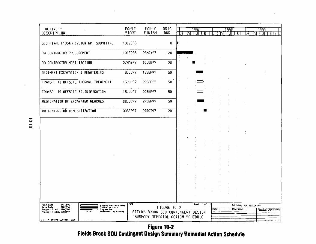
oIo
A C T I V I T Y EARLY EARLY ORIGDESCRIPTION START FINISH DUR
SOU FINAL (100*) DESIGN RPT SUBMITTAL 10DEC% 0
RA CONTRACTOR PROCUREMENT 10DEC% 26MAYR7 120
RA CONTRACTOR MOBILIZATION 27MAY97 23JUN97 20
SEDIMENT EXCAVATION & DEHATERING 8JUL<V7 155EP97 50
TRANSP TO OFF5ITE THERMAL TREATMENT 15JUL97 225EP97 50
TRAN5P. TO OFF5ITE SOLIDIFICATION 15JUL97 225EP97 50
RESTORATION OF EXCAVATED REACHES 22JUL97 29SEPq7 50
RA CONTRACTOR DEMOBLIIZATION 30SEP97 270CT97 20
Plot Date MFEB95 i ————————— i Aridity **-/FK|Y D*tt* F**Data Date 10DEC06 MMI n CMttcil **"*? hlGURL 10Project Start lOOEC* ^mtmf=i Pr n. Br iuur\i_ IUProject Finish 2700197 <>/*• miMim/FI* teti.ity FIELDS BROOK SOU CON1
'SUMMARY REMEDIAL A C T . .. .. „..
1997 iqqe iwJl IAI ui D| j| i N i ui DI j| mi i |j| mi j
>•
; •
I=D
: "era"
•
n Shwt ' °f ' 12/21/91, 30« DESICK RPI
•- Date Revision Chech_°'' ftr("inypt)TNGFNT nFSTHN —— —————————————— ——— - - - --TON srHFnntr — —————————— -^ — - ——
(c) Prinavera Systems, Inc ——— ————————————— — - ———
Figure 10-2Fields Brook SOU Contingent Design Summary Remedial Action Schedule

11.0 PROCUREMENT STRATEGY
The procurement process described will fulfill the ROD requirements because the remedial actionwill be performed in the most cost-effective manner. The design will be based on establishedperformance criteria to the maximum extent practical. The design will allow the remediationcontractors to use specialty knowledge.
11.1 STANDARD APPROACH TO PROCUREMENT
11.1.1 General
The procurement manager is responsible for all contractual matters beginning with bidderprequalification, preparation of bid packages, solicitation, evaluation, and award. This includesadministration of changes, negotiations of amendments, and closeout of subcontracts. The
procurement manager is supported by other procurement specialists as required. Projectsuperintendents manage field contract administration with the assistance of other disciplines,including cost and scheduling, safety and health, and quality assurance.
The type of subcontract to be used is based on the scope of work, knowledge of the site,available technology, ability to provide detailed specifications, schedule, and capabilities of theprospective subcontractors. The various subcontract types can be grouped into four broadcategories:
• Firm, fixed lump-sum price, which is used when the scope can be completely defined and siteconditions are so well-established that changes are expected to be minimal
• Firm, fixed-unit price, which is used when tasks are well-defined but quantifying the work isnot possible or cost-effective
A9112/20/95 6:42pm 11*1

• Cost reimbursable, fixed fee, which may be used when the scope is not well-defined or issubject to change, or when conditions are variable
• Cost reimbursable, award fee, which also may be appropriate when the scope is notwell-defined or is subject to change, or when conditions are variable
11.1.2 Subcontract Strategy and Management
The decision to subcontract work (versus direct hire) is based on the client's needs and on costand schedule efficiencies.
The subcontract strategy is to balance specialty and local subcontractors, local direct hires,trained supervisors, and craft personnel to achieve a cost-effective job with built-in control ofschedule and quality. The approach to key aspects of subcontracting is as follows:
1. Lead times for subcontract preparation, mobilization, and materials are scheduled activities.Lead time is minimized by scoping the subcontracts into traditional and specialty tasks,matched to area resources. Prepared generic specifications are modified to accommodatespecific project needs.
2. The period of performance is specified in each subcontract, with respective milestone datesidentified. The subcontractor participates in the scheduling process, including resourceloading and updates.
3. Subcontractors may either abide by project-specific quality assurance/quality control plan(s)or provide their own. A subcontractor's plan must meet or exceed specified qualityassurance/quality control requirements and be reviewed and approved before it is used. Thequality of subcontractor work will constantly be monitored. Noncompliant work is identifiedand corrected in accordance with the terms of the subcontract.
A9U2/20/95 6:42pm

4. Subcontractors' work will be accepted only when all requirements of the subcontract aresatisfactorily completed.
11.1.3 Subcontract Procurement Process
The following steps are taken after the decision has been made to subcontract work for a project:(1) presolicitation, (2) solicitation, (3) evaluation, and (4) award.
Presolicitation
Potential bidders identified in the bidders list are selected based on past experience with the sametype of projects, references, information from the Thomas Register, online access to theU.S. Small Business Administration's Procurement Automated Supplier System, and othersources.
Presolicitation includes bidder prequalification and preparation of a bid package, which primarilyconsists of the following sections: (1) information and instructions to bidders, (2) generalconditions and special conditions, (3) schedule of quantities and prices, (4) scope of work andtechnical specifications, and (5) drawings if applicable.
Information and instructions to bidders. Information to bidders is provided solely for theconvenience of the bidders. This section normally summarizes information such as the projectdescription, site location and description, and climatological, geotechnical, and other conditions.
Instructions to bidders outline the requirements for such things as preparation and submission ofbids, disposition of late bids, submission of sample insurance certificates bid, and requirementsfor payment and performance bonds.
General and special conditions. General and special conditions are included in all bid packagesAny client or government flow-down terms and conditions are also included.
A91I2/3V95 6:42pm 1 1 ~3
Schedule of quantities and prices. This section breaks out the work into individual pay itemsfor the purpose of identifying and clarifying the work for which payment would be made. For
indefinite quantity work, estimated quantities are included to provide the subcontractor with anindication of the quantity of work. Based on the information provided in this section, thesubcontractor submits prices for the items of work listed.
Scope of work and technical specifications. The scope of work is based on the statement ofwork provided by the client. The technical team prepares the scope of work as directed by theclient and based on the statement of work. The scope of work describes the technology thatwould be used to obtain the objective in the statement of work. The technical specificationdocument accompanies the scope of work and provides the technical detail for the applicabletechnologies stated in the scope of work.
Drawings. The technical team prepares technical drawings based on the information obtainedfrom the site and provided by the client. Technical drawings are also prepared for the applicabletechnologies addressed in the technical specification.
Solicitation
If deemed necessary because of difficult site conditions or other factors, bidders are invited toattend a prebid meeting. This meeting is attended by representatives of as many disciplines asrequired—normally procurement, construction, and safety and health. During this meeting, allparts of the bid package are reviewed with the bidders. After the bid package has beenreviewed, a tour of the site is taken. Questions and answers regarding the solicitation arepublished for all bidders.
Evaluation
The evaluation process starts with the bid opening. The project management team, including theprocurement manager, is present to open the sealed bids. All bids are evaluated for criteria such
A9112/30/95 6:42pm 11-4
as past experience, professional registration(s), commercial compliance, technical capabilities,safety statistics, the quality assurance/quality control program, and price. The bids are tabulated
on a tabulation of bids form. A recommendation is made to award to the lowest cost, technicallyqualified, responsible, and responsive bidder. If required by the client, the recommendation foraward and all supporting documentation would be forwarded to the client for approval before thesubcontract is awarded.
Award
After subcontract award and before the start of work, a preconstruction meeting is held to reviewagain the subcontract requirements. Emphasis is on submittal requirements, site work rules,schedule, invoicing, etc.
11.2 ALTERNATE APPROACH TO PROCUREMENT
The alternate approach to procurement of a subcontract process is the direct hire approach. Thisapproach would be used if it is shown to be more cost-effective than subcontracting the work.
The technical team prepares the scope of work and detailed equipment specifications based on theclient's design and performance requirements. The scope of work and specification areforwarded to the client for approval. Upon approval from the client, equipment is bought,rented, or leased from vendors and services from the local labor market. The technical teaminstalls the equipment and operates the process in compliance with the performance criteria set bythe client.
The technical team adheres to the quality assurance project plan prepared by the QualityAssurance Department. The quality assurance manager appointed to the project has independentoversight responsibility for the work performed. Safety and health personnel prepare the safetyand health plan, and a safety representative is onsite to ensure that the technical team adheres to
2/20/95 6:42pm 11-5

the plan. The quality assurance project plan and safety and health plan are approved by the client
before use.
11.3 RECOMMENDED APPROACH
The recommended approach for the Fields Brook remedial action is to subcontract the work usinga firm, fixed lump-sum price and firm, fixed-unit price subcontract to a single remediationsubcontractor. This approach is suitable because (1) the tasks and scope are well-defined, and(2) the site conditions are well-established, but it is not possible to quantify the amount of work.This will maximize the competition while also maximizing the control at a single point.However, during development of design documents, if it becomes apparent that the alternateapproach (Section 11.2) is more cost-effective, that approach will be adopted.
There are many very specialized subcontractors with years of experience in water treatment,stabilization and solidification, and other applicable processes. These subcontractors are abreastof the current technical developments, and some have patented processes in the aforementionedtreatment technology areas that are very efficient. Using these types of subcontractors would bemore efficient and cost-effective for the remediation process.
11.3.1 Base Design
The recommended approach for the base design would be as follows:
• The remediation contractor would provide overall project management, reviewingdeliverables, verifying quantities, etc.
• A single remediation subcontractor would be selected as agent.
A9II2/20/95 6;42pm 11-6

• The remediation contractor could be a general contractor supported by three specialtysubcontractors in the areas of thermal treatment, water treatment, stabilization andsolidification; or the remediation contractor could be one of the specialty subcontractorssupported by a general contractor and two specialty subcontractors. Either case wouldmaximize competition while also maximizing control at one point of contact.
11.3.2 Contingent Design
The recommended approach in the contingent design would be as follows:
• The remediation contractor would provide overall project management, reviewingdeliverables, verifying quantities, etc.
• The contractor would select two subcontractors: an excavation and transport subcontractorand a disposal facility. Any manifests would be signed by the designated entity.
A9112/3V95 6:42pm 1 I
12.0 FINAL DESIGN WORK PLAN
The final design (60, 90, and 100 percent) work plan for the Fields Brook SOU remedial action,as required by the ROD, is provided as Appendix A, This work plan was prepared to meet therequirements of the SOW, Section 8.
The final design work plan defines the interfaces, work tasks, project deliverables, milestones,and schedule associated with preparing the remedial design for excavation of the sediment fromFields Brook, thermal or solidification treatment of the sediments, and disposal of the treatedsediment onsite in a landfill. It also identifies the process that will be used to developprocedures, specifications, and drawings. The design process includes adhering to standardengineering procedures, modifying existing documents where possible, involving construction andfield remediation personnel in reviews, developing construction work plans and schedules thatminimize time in the field, and coordinating with the FBPRPO and regulatory agencies. Thisfinal design work plan was submitted to EPA on August 26, 1993; comments were received onDecember 7, 1993; and comments were clarified during a teleconference on March 3, 1994. Tobe consistent with the Phase II sediment sampling, this work plan incorporates these commentsand contains the updated quantities in Table 3-2, "Summary of Estimated Volumes"; Figures 3-2through 3-8, "Compounds Detected in Sediment Greater than USEPA 11/93 Clean Up Goals inExposure Units 1 through 10"; Figure 8-1, "Process Flow Diagram;" and ARARs from thedesign investigation reports.
A9112/20/W 6:42pm 12-1
13.0 ACCESS STRATEGY
To remediate Fields Brook, it will be necessary to obtain access to properties near the brook.The strategy for obtaining access will depend on the purpose for obtaining entry, the degree ofdisturbance required, and the length of time required to complete activities on the property. Thissection describes the factors considered in evaluating access requirements and outlines a strategyfor obtaining the necessary access rights.
The access process is to:
• Establish areas to be remediated• Obtain property data for all areas to be remediated• Define space and access needs• Determine degree of disturbance• Adjust access design• Develop access schedule• Estimate access value• Establish type of access agreement• Negotiate with owners• Adjust access design
The first step in the process of obtaining access is to establish the areas requiring remediation.The SQDI report establishes the reaches and exposure units where remediation is needed, whichare along reaches 1, 2-1, 2-2, 3, 4, 5-1, 5-2, 6, 11-1, 11-2, and 11-4. After EPA's approval ofthe SQDI report, county deed records will be researched for property title data for properties onboth sides of the brook and for any properties between the reaches and the closest public road.Information from the records research will be used to delineate property boundaries, easements,and right-of-ways on maps. Data to be obtained during the records research will include:
A9112/20/95 6:42pm 13-1

• Owner's name• Owner's address• Owner's phone number• Property tax record number
• Previous owners• Dates of title transfer• Easements• Liens
Next, the space requirements and access needs for each reach will be established in the60 percent remedial design submittal, and maps will be prepared. The maps will identify thedegree of disturbance expected for each property. In some cases, the remedial design accesscould be revised to reduce the number of properties affected or to use an industrially ownedproperty rather than a privately owned property. After the 60 percent remedial design report issubmitted, the schedule for obtaining the access for each property will be estimated. The nextstep is to appraise the properties and establish the value of the required access rights.
After the degree of required disturbance, the access schedule, and the value of the access rightsare established, the appropriate type of access agreement will be determined. Access agreementscould include easements, leases, and fee acquisitions. For example, easements could be requiredto obtain access to monitoring points, leases could be used for haul roads and other temporarystructures, and fee acquisitions could be required for treatment and disposal facilities.
When the 60 percent remedial design report is submitted to EPA, negotiations with the affectedlandowners will begin. Negotiations with landowners frequently result in changes in the accessstrategy, with resultant changes in the remedial design. Because negotiations will parallel EPA'sreview of the 60 percent remedial design and possibly the preparation of the 90 percent remedialdesign, any changes required by the landowners will be reflected in the 90 percent design report.After completion of negotiations, the appropriate real estate access agreements will be preparedfor signature by the landowners.
A9112/20/95 6:42pm 13~2

REFERENCES
CH2M Hill, 1985. Remedial Investigation - Fields Brook Site, Ashtabula, Ohio (March).
CH2M Hill, 1986. Feasibility Study - Fields Brook Sediment Operable Unit, Ashtabula, Ohio(July).
EPA (U.S. Environmental Protection Agency), 1986a. Superfund Record of Decision: FieldsBrook Sediment, Ohio, EPA/ROD/RO5-86/035, Office of Emergency and RemedialResponse, Washington, D.C. (September 30).
EPA, 1986b. Draft Guidelines for Permit Applications and Demonstration Test Plans for PCBIncinerators, TS-798, Office of Toxic Substances, Chemical Regulation Branch,Washington, D.C. (May 28).
EPA, 1986c. Superfund Public Health Evaluation Manual EPA 540/1-86/060, Exhibit A-l,Office of Emergency and Remedial Response, Washington, D.C. (October 1).
EPA, 1989a. Fields Brook - Sediment Operable Unit Statement of Work, Section 8,86C3609A-703 (March 14).
EPA, 1989b. Unilateral Administrative Order Pursuant to Section 106 of the ComprehensiveEnvironmental Response, Compensation, and Liability Act of1980 as Amended, in the Matterof Fields Brook Site, Ashtabula, Ohio, EPA Docket No. V-W-89-C-008, EPA Region V,Chicago (March 22).
EPA, 1989c, Hazardous Waste Incinerator Guidance Series: Volume 1 - Guidance on SettingPermit Conditions and Reporting Trial Burn Results, EPA 625/6-89/019, Prepared byAcurex.
A9112/2CV95 6:42pm R*l
Gradient, 1993. VOC Air Concentrations from Excavation Activities at Fields Brook.
Hanlon, E. J., 1993a. Letter from E. J. Hanlon (EPA Region V) to J. A. Heimbuch (demaximis, inc., Lavonia, Michigan), Subject: "Cleanup Goals Issue." (November 1).
Hanlon, E. J., 1993b. Letter from E. J. Hanlon (EPA Region V) to J. A. Heimbuch (demaximis, ire., Lavonia, Michigan), Subject: "Comments to Draft Final Design (60, 90, and100 percent) Work Plan, August 1993, Fields Brook Superfund Site" (December 7).
Hanlon, E. J., 1994. Letter from E. J. Hanlon (EPA Region V) to S. Golyski and L. Weyer(CH2M Hill), Subject: "Conference Call to Discuss 12/7/93 Comments to the Draft Final•Design (60, 90, and 100 Percent) Work Plan" (February 10).
Hershfield, D. M., 1961. Rainfall Frequency Atlas of the United States for Durations from30 Minutes to 24 Hours and Return Periods from 1 to 100 Years, Technical Paper 40,prepared for Engineering Division, Soil Conservation Service, U.S. Department ofAgriculture, U.S. Department of Commerce, Weather Bureau, Washington, D.C.
McConnel, B. C. 1994. Letter from B. C. McConnel (Bechtel) to E. J. Hanlon (EPA, RegionV), Subject: "Draft Final Design (60, 90, and 100 Percent) Work Plan" (February 23).
WCC (Woodward-Clyde Consultants), 1992. SOU Sediment Quantification Design InvestigationReport, Phase I, Fields Brook Site, Ashtabula, Ohio, Rev. 0, prepared for FBPRPO byWCC, Solon, Ohio (October).
WCC, 1994a. Phase I Source Control Remedial Investigation Report, Fields Brook Site,Ashtabula, Ohio, prepared for FBPRPO by WCC. Solon, Ohio (August).
A9112/20/95 7:14pm R Z

WCC, 1994b. SOU Sediment Quantification Design Investigation, Phase II, Sampling Design,Field Sampling Plan, Addendum 1, Fields Brook Site, Ashtabula, Ohio, prepared forFBPRPO by WCC, Solon, Ohio (February).
WCC, 1995a. Draft Phase II Sediment Quantification Design Investigation, Floodplain Mapsand Analytical Results, SOU, Fields Brook Site, Ashtabula, Ohio, prepared for FBPRPO byWCC, Solon, Ohio (February).
WCC, 1995b. Sediment Dewatering and Water Treatment Design Investigation, Fields BrookSite, Ashtabula, Ohio, prepared for FBPRPO by WCC, Solon, Ohio (February).
WCC, 1995c. Thermal Treatment Design Investigation, Fields Brook Site, Ashtabula, Ohio,prepared for FBPRPO by WCC, Solon, Ohio (February).
WCC, 1995d. Solidification Design Investigation, Fields Brook Site, Ashtabula, Ohio, preparedfor FBPRPO by WCC, Solon, Ohio (February).
WCC, 1995e. Facility Siting Design Investigation, Fields Brook Site, Ashtabula, Ohio, preparedfor FBPRPO by WCC, Solon, Ohio (February).
A9112/30/95 7:lSpm R~3

APPENDIX A
Final Design Work Plan
(Transmitted by letter from B. C. McConnel to J. A. Heimbuch dated May 24, 1994,Subject: Draft Final Design (60, 90, and 100 Percent) Work Plan, May 1994.)
A9112/2VW 642pm A- 1

Appendix A to the Preliminary Design Report
FINAL DESIGN (60-, 90-, and 100-PERCENT) WORK PLANFOR THE FIELDS BROOK SITE
SEDIMENT OPERABLE UNIT REMEDIAL ACTION
FEBRUARY 1995
Prepared for
Fields Brook PRP Organization
By
Bechtel Associates Professional Corporation of Ohio

CONTENTS
Page
FIGURES . . . . . . . T . . . . . . . . . . . . . . . . . . . . . . . . . . . . . . . . . . . . . . . . . . . . v iTABLES . . . . . . . . . . . . . . . . . . . . . . . . . . . . . . . . . . . . . . . . . . . . . . . . . . . . v iACRONYMS AND INITIALISMS . . . . . . . . . . . . . . . . . . . . . . . . . . . . . . . . . . . . vii
1.0 INTRODUCTION . . . . . . . . . . . . . . . . . . . . . . . . . . . . . . . . . . . . . . . . . . . . 1
2.0 BACKGROUND . . . . . . . . . . . . . . . . . . . . . . . . . . . . . . . . . . . . . . . . . . . . i2.1 SITE LOCATION AND DESCRIPTION . . . . . . . . . . . . . . . . . . . . . . . . . . 12.2 SITE HISTORY . . . . . . . . . . . . . . . . . . . . . . . . . . . . . . . . . . . . . . . . . . 52.3 SITE ACCESS . . . . . . . . . . . . . . . . . . . . . . . . . . . . . . . . . . . . . . . . . . 5
3.0 PROJECT OBJECTIVES . . . . . . . . . . . . . . . . . . . . . . . . . . . . . . . . . . . . . . . 7
4.0 REGULATORY COMPLIANCE . . . . . . . . . . . . . . . . . . . . . . . . . . . . . . . . . . 224.1 FEDERAL REGULATIONS . . . . . . . . . . . . . . . . . . . . . . . . . . . . . . . . . . 22
4.1.1 Resource Conservation and Recovery Act . . . . . . . . . . . . . . . . . . . . . . 234.1.2 Occupational Safety and Health Administration (OSHA) . . . . . . . . . . . . . 234.1.3 Clean Air Act . . . . . . . . . . . . . . . . . . . . . . . . . . . . . . . . . . . . . . . 244.1.4 Executive Orders . . . . . . . . . . . . . . . . . . . . . . . . . . . . . . . . . . . . . 244.1.5 Clean Water Act . . . . . . . . . . . . . . . . . . . . . . . . . . . . . . . . . . . . . 244.1.6 CERCLA . . . . . . . . . . . . . . . . . . . . . . . . . . . . . . . . . . . . . . . . . . 244.1.7 Toxic Substances Control Act (TSCA) . . . . . . . . . . . . . . . . . . . . . . . . 244.1.8 ARARs for Dewatering and Excavation . . . . . . . . . . . . . . . . . . . . . . . 244.1.9 ARARs for Water Treatment . . . . . . . . . . . . . . . . . . . . . . . . . . . . . . 274.1.10 ARARs for Thermal Treatment . . . . . . . . . . . . . . . . . . . . . . . . . . . . 294.1.11 ARARs for Solidification . . . . . . . . . . . . . . . . . . . . . . . . . . . . . . . 314.1.12 ARARs for Facility Siting . . . . . . . . . . . . . . . . . . . . . . . . . . . . . . . 33
4.3 LOCAL (COUNTY) REGULATIONS . . . . . . . . . . . . . . . . . . . . . . . . . . . . 36
5.0 DESIGN PROJECT ORGANIZATION . . . . . . . . . . . . . . . . . . . . . . . . . . . . . . 36
6.0 QUALITY ASSURANCE . . . . . . . . . . . . . . . . . . . . . . . . . . . . . . . . . . . . . . . 38
7.0 HEALTH AND SAFETY . . . . . . . . . . . . . . . . . . . . . . . . . . . . . . . . . . . . . . . 38
8.0 SCOPE OF WORK . . . . . . . . . . . . . . . . . . . . . . . . . . . . . . . . . . . . . . . . . . . 398.1 DIVISION 00800 - SPECIAL CONDITIONS . . . . . . . . . . . . . . . . . . . . . . . . 39
8.1.1 Definition of Terms (SC-1) . . . . . . . . . . . . . . . . . . . . . . . . . . . . . . . 398.1.2 Abbreviations (SC-2) . . . . . . . . . . . . . . . . . . . . . . . . . . . . . . . . . . . 398.1.3 Codes and Standards (SC-3) . . . . . . . . . . . . . . . . . . . . . . . . . . . . . . 398.1.4 Regulatory Requirements (SC-4) . . . . . . . . . . . . . . . . . . . . . . . . . . . . 408.1.5 Security (SC-5) . . . . . . . . . . . . . . . . . . . . . . . . . . . . . . . . . . . . . . 408.1.6 Dust and Erosion Control (SC-6) . . . . . . . . . . . . . . . . . . . . . . . . . . . 40
A2U.F2/17/93 *:11pm 111

CONTENTS (continued)
Page
8.1.7 Protection of Property (SC-7) . . . . . . . . . . . . . . . . . . . . . . . . . . . . . 408.1.8 Site Conditions (SC-8) . . . . . . . . . . . . . . . . . . . . . . . . . . . . . . . . . . 408.1.9 Equipment and Materials (SC-9) . . . . . . . . . . . . . . . . . . . . . . . . . . . . 408.1.10 Health and Safety (SC-10) . . . . . . . . . . . . . . . . . . . . . . . . . . . . . . . 418.1.11 Decontamination (SC-11) . . . . . . . . . . . . . . . . . . . . . . . . . . . . . . . 418.1.12 Utilities (SC-12) . . . . . . . . . . . . . . . . . . . . . . . . . . . . . . . . . . . . . 428.1.13 Cleaning Up (SC-13) . . . . . . . . . . . . . . . . . . . . . . . . . . . . . . . . . . 428.1.14 Construction Quality Assurance (SC-14) . . . . . . . . . . . . . . . . . . . . . . 428.1.15 Spill Control (SC-15) . . . . . . . . . . . . . . . . . . . . . . . . . . . . . . . . . . 428.1.16 Cleanup Verification (SC-16) . . . . . . . . . . . . . . . . . . . . . . . . . . . . . 428.1.17 Analytical Services (SC-17) . . . . . . . . . . . . . . . . . . . . . . . . . . . . . . 438.1.18 Site History (SC-18) . . . . . . . . . . . . . . . . . . . . . . . . . . . . . . . . . . 438.1.19 Schedule (SC-19) . . . . . . . . . . . . . . . . . . . . . . . . . . . . . . . . . . . . 438.1.20 Community Relations (SC-20) . . . . . . . . . . . . . . . . . . . . . . . . . . . . 43
8.2 GENERAL REQUIREMENTS - DIVISION 01000 . . . . . . . . . . . . . . . . . . . . 438.2.1 Summary of Work (01010) . . . . . . . . . . . . . . . . . . . . . . . . . . . . . . . 438.2.2 Mobilization/Demobilization (01020) . . . . . . . . . . . . . . . . . . . . . . . . . 468.2.3 Layout of Work Zones and Surveys (01050) . . . . . . . . . . . . . . . . . . . . 468.2.4 Preconstruction Conference (01210) . . . . . . . . . . . . . . . . . . . . . . . . . . 468.2.5 Progress Meetings (01220) . . . . . . . . . . . . . . . . . . . . . . . . . . . . . . . 468.2.6 Submittals (01300) . . . . . . . . . . . . . . . . . . . . . . . . . . . . . . . . . . . . 468.2.7 Photographs (01310) . . . . . . . . . . . . . . . . . . . . . . . . . . . . . . . . . . . 478.2.8 Temporary Construction Facilities (01500) . . . . . . . . . . . . . . . . . . . . . 478.2.9 Traffic Regulations (01600) . . . . . . . . . . . . . . . . . . . . . . . . . . . . . . . 478.2.10 Project Closeout (01700) . . . . . . . . . . . . . . . . . . . . . . . . . . . . . . . . 47
8.3 SITE WORK - DIVISION 02000 . . . . . . . . . . . . . . . . . . . . . . . . . . . . . . . 488.3.1 Site Preparation (02001) . . . . . . . . . . . . . . . . . . . . . . . . . . . . . . . . . 488.3.2 Clearing and Grubbing (02010) . . . . . . . . . . . . . . . . . . . . . . . . . . . . 488.3.3 Office Trailer and Sanitary Facilities (02020) . . . . . . . . . . . . . . . . . . . . 488.3.4 Earthwork (02110) . . . . . . . . . . . . . . . . . . . . . . . . . . . . . . . . . . . . 488.3.5 Stream Diversion (02120) . . . . . . . . . . . . . . . . . . . . . . . . . . . . . . . 498.3.6 Material Handling (02130) . . . . . . . . . . . . . . . . . . . . . . . . . . . . . . . 498.3.7 Dewatering Sediments for Treatment (02140) . . . . . . . . . . . . . . . . . . . . 498.3.8 Landfill (02200) . . . . . . . . . . . . . . . . . . . . . . . . . . . . . . . . 498.3.9 Monitoring Wells (02300) . . . . . . . . . . . . . . . . . . . . . . . . . . 498.3.10 Permanent Fencing (02400) . . . . . . . . . . . . . . . . . . . . . . . . . 508.3.11 Site Restoration (02500) . . . . . . . . . . . . . . . . . . . . . . . . . . 508.3.12 Landfill Closure (02600) . . . . . . . . . . . . . . . . . . . . . . . . . . . 50
8.4 SPECIAL CONSTRUCTION - DIVISION 13000 . . . . . . . . . . . . . . . . . . . . . 508.4.1 Solidification (13100) . . . . . . . . . . . . . . . . . . . . . . . . . . . . 508.4.2 Wastewater Treatment (13200) . . . . . . . . . . . . . . . . . . . . . . . 508.4.3 Thermal Treatment (13300) . . . . . . . . . . . . . . . . . . . . . . . 528.4.4 Operation and Maintenance (13400) . . . . . . . . . . . . . . . . . . . . 53
A24I.F2/17/95 4:llpn

CONTENTS (continued)
Page
8.5 DRAWINGS AND PROCESS FLOW DIAGRAMS . . . . . . . . . . . . . . . . . . . . 538.5.1 Final Design Drawings . . . . . . . . . . . . . . . . . . . . . . . . . . . . . . . . . 538.5.2 System-Specific Drawings . . . . . . . . . . . . . . . . . . . . . . . . . . . . . . . . 53
8.6 BID SPECIFICATIONS AND DOCUMENTS . . . . . . . . . . . . . . . . . . . . . . . 54
9.0 FINAL DESIGN PROJECT MANAGEMENT . . . . . . . . . . . . . . . . . . . . . . . . . . 559.1 FINAL DESIGN BUDGET AND COST CONTROL . . . . . . . . . . . . . . . . . . . 559.2 ENGINEERING SCHEDULES . . . . . . . . . . . . . . . . . . . . . . . . . . . . . . . . 559.3 MONTHLY ENGINEERING PROGRESS REPORT . . . . . . . . . . . . . . . . . . . 559.4 SUBCONTRACTORS . . . . . . . . . . . . . . . . . . . . . . . . . . . . . . . . . . . . . . 55
10.0 SCHEDULE . . . . . . . . . . . . . . . . . . . . . . . . . . . . . . . . . . . . . . . . . . . . . . 5610.1 INTERMEDIATE (60-PERCENT) SUBMITTAL . . . . . . . . . . . . . . . . . . . . 56
10.1.1 Specifications . . . . . . . . . . . . . . . . . . . . . . . . . . . . . . . . . . . . . . . 5610.1.2 Drawings . . . . . . . . . . . . . . . . . . . . . . . . . . . . . . . . . . . . . . . . . 5610.1.3 Cost Estimate . . . . . . . . . . . . . . . . . . . . . . . . . . . . . . . . . . . . . . 56
10.2 PREFINAL (90-PERCENT) SUBMITTAL . . . . . . . . . . . . . . . . . . . . . . . . . 5610.2.1 Specifications . . . . . . . . . . . . . . . . . . . . . . . . . . . . . . . . . . . . . . . 5610.2.2 Drawings . . . . . . . . . . . . . . . . . . . . . . . . . . . . . . . . . . . . . . . . . 5610.2.3 Cost Estimate . . . . . . . . . . . . . . . . . . . . . . . . . . . . . . . . . . . . . . 59
10.3 FINAL (100-PERCENT) SUBMITTAL . . . . . . . . . . . . . . . . . . . . . . . . . . . 5910.4 CONTENTS OF PROPOSAL PACKAGES . . . . . . . . . . . . . . . . . . . . . . . . 59
11.0 FINAL DESIGN CONTINGENCIES . . . . . . . . . . . . . . . . . . . . . . . . . . . . . . . 59
ATTACHMENTS
A Specifications for Construction of Sediment Operable Unit . . . . . . . . . . . . . . . . . . A-lB List of Drawings . . . . . . . . . . . . . . . . . . . . . . . . . . . . . . . . . . . . . . . . . . . B-1
A2U.F2/17/95 4:llpm
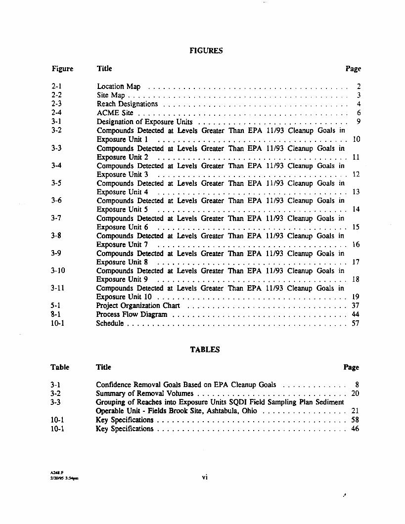
FIGURES
Figure Title Page
2-1 Location Map . . . . . . . . . . . . . . . . . . . . . . . . . . . . . . . . . . . . . . . . 22-2 Site Map . . . . . . . . . . . . . . . . . . . . . . . . . . . . . . . . . . . . . . . . . . . . 32-3 Reach Designations . . . . . . . . . . . . . . . . . . . . . . . . . . . . . . . . . . . . . 42-4 ACME Site . . . . . . . . . . . . . . . . . . . . . . . . . . . . . . . . . . . . . . . . . . 63-1 Designation of Exposure Units . . . . . . . . . . . . . . . . . . . . . . . . . . . . . . 93-2 Compounds Detected at Levels Greater Than EPA 11/93 Cleanup Goals in
Exposure Unit 1 . . . . . . . . . . . . . . . . . . . . . . . . . . . . . . . . . . . . . . 103-3 Compounds Detected at Levels Greater Than EPA 11/93 Cleanup Goals in
Exposure Unit 2 . . . . . . . . . . . . . . . . . . . . . . . . . . . . . . . . . . . . . . 113-4 Compounds Detected at Levels Greater Than EPA 11/93 Cleanup Goals in
Exposure Unit 3 . . . . . . . . . . . . . . . . . . . . . . . . . . . . . . . . . . . . . . 123-5 Compounds Detected at Levels Greater Than EPA 11/93 Cleanup Goals in
Exposure Unit 4 . . . . . . . . . . . . . . . . . . . . . . . . . . . . . . . . . . . . . . 133-6 Compounds Detected at Levels Greater Than EPA 11/93 Cleanup Goals in
Exposure Unit 5 . . . . . . . . . . . . . . . . . . . . . . . . . . . . . . . . . . . . . . 143-7 Compounds Detected at Levels Greater Than EPA 11/93 Cleanup Goals in
Exposure Unit 6 . . . . . . . . . . . . . . . . . . . . . . . . . . . . . . . . . . . . . . 153-8 Compounds Detected at Levels Greater Than EPA 11/93 Cleanup Goals in
Exposure Unit 7 . . . . . . . . . . . . . . . . . . . . . . . . . . . . . . . . . . . . . . 163-9 Compounds Detected at Levels Greater Than EPA 11/93 Cleanup Goals in
Exposure Unit 8 . . . . . . . . . . . . . . . . . . . . . . . . . . . . . . . . . . . . . . 173-10 Compounds Detected at Levels Greater Than EPA 11/93 Cleanup Goals in
Exposure Unit 9 . . . . . . . . . . . . . . . . . . . . . . . . . . . . . . . . . . . . . . 183-11 Compounds Detected at Levels Greater Than EPA 11/93 Cleanup Goals in
Exposure Unit 10 . . . . . . . . . . . . . . . . . . . . . . . . . . . . . . . . . . . . . . 195-1 Project Organization Chart . . . . . . . . . . . . . . . . . . . . . . . . . . . . . . . . 378-1 Process Flow Diagram . . . . . . . . . . . . . . . . . . . . . . . . . . . . . . . . . . . 4410-1 Schedule . . . . . . . . . . . . . . . . . . . . . . . . . . . . . . . . . . . . . . . . . . . . 57
TABLES
Table Title Page
3-1 Confidence Removal Goals Based on EPA Cleanup Goals . . . . . . . . . . . . . 83-2 Summary of Removal Volumes . . . . . . . . . . . . . . . . . . . . . . . . . . . . . . 203-3 Grouping of Reaches into Exposure Units SQDI Field Sampling Plan Sediment
Operable Unit - Fields Brook Site, Ashtabula, Ohio . . . . . . . . . . . . . . . . . 2110-1 Key Specifications . . . . . . . . . . . . . . . . . . . . . . . . . . . . . . . . . . . . . . 5810-1 Key Specifications . . . . . . . . . . . . . . . . . . . . . . . . . . . . . . . . . . . . . . 46
A24I.F2/20/95 5:J4pm VI

ACRONYMS AND IN1TIALISMS
ARAR applicable or relevant and appropriate requirementBMP best management practiceCERCLA Comprehensive Environmental Response, Compensation, and Liability ActCQAP construction quality assurance planDI design investigationEPA U.S. Environmental Protection AgencyFBPRPO Fields Brook Potentially Responsible Parties OrganizationNPDES National Pollutant Discharge Elimination SystemNPL National Priorities ListOSHA Occupational Safety and Health AdministrationPCB polychlorinated biphenylPOTW publically owned treatment worksROD record of decisionSAP sampling and analysis planSARA Superfund Amendments and Reauthorization ActSOU sediment operable unitSOW statement of workTSCA Toxic Substances Control Act
A24«.F2/17/93 4:l Vll
1.0 INTRODUCTION
This final design work plan for the sediment operable unit (SOU) remedial action for the FieldsBrook site located in Ashtabula, Ohio, has been prepared to meet the requirements of thestatement of work (SOW) Section 8 (86C3609A-703 dated March 1989) and is a stand-aloneattachment to the preliminary (30-percent) design report. This final design work plan defines theinterfaces, work tasks, project deliverables, milestones, and schedules associated with preparingthe remedial design for excavation of sediment from Fields Brook, thermal or solidificationtreatment of the sediments, and storing the treated sediment onsite within a landfill. It alsoidentifies the process that will be used to develop procedures, specifications, and drawings. Thedesign process includes adhering to standard engineering procedures, modifying existingdocuments where possible, involving construction and field remediation personnel in reviews,developing construction work plans and schedules that minimize time in the field, andcoordinating with the Fields Brook Potentially Responsible Parties Organization (FBPRPO) andregulatory agencies.
This work plan is organized into 11 sections. Section 2.0 describes the site location and features,as well as a brief history of the site. Section 3.0 presents the project objectives, which includepreparation of a preliminary design report and an intermediate (60-percent), prefmal (90-percent),and final (100-percent) design. Section 4.0 summarizes regulatory requirements and compliancedocuments including applicable or relevant and appropriate requirements (ARARs), which willhave been developed in the preliminary (30-percent) report. Section 5.0 discusses the projectorganization. Section 6.0 discusses the approach to quality assurance during remedial design.Section 7.0 presents the health and safety plans for the remedial design period. Section 8.0presents the scope of work. This section details six tasks, which include special conditions,general requirements, site work, special construction, drawings, and bid specifications anddocuments. Section 9.0 discusses project management activities during remedial design includingdocument control, review meetings, and progress reporting. Section 10.0 provides the projectschedule and the information that will be provided with the intermediate (60-percent), prefmal(90-percent), final (100-percent) submittals and content of the proposal package. Section 11.0presents a list of contingencies to the final design.
Revision of the discussions, concepts, and approaches presented in this work plan may benecessary as work progresses.
2.0 BACKGROUND
2.1 SITE LOCATION AND DESCRIPTION
Fields Brook is located in Ashtabula, Ashtabula County, in northeastern Ohio (Figure 2-1). Thebrook drains a 5.6-mile2 watershed, the eastern portion draining Ashtabula township and thewestern portion draining the city of Ashtabula (Figure 2-2).
The 3.5-mile stretch of main channel begins just south of U.S. Highway 20, about 1 mile east ofState Highway 11. From the main channel, the stream flows northwesterly, under Highway 20and Cook Road, to just north of Middle Road. Then the stream is made up of a series of reaches(Figure 2-3) and flows westerly to its confluence with the Ashtabula River. From Cook Road
A24I.P2/17/93 4:llpm

Figure 2-1Location Map
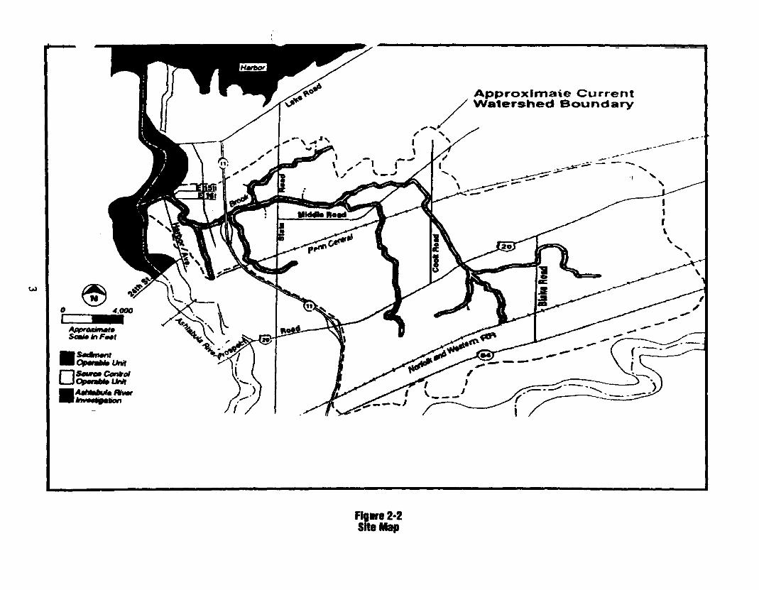
Approximate
Figure 2-2Site Map

CMe

downstream to Highway 11, the stream flows through an industrial area. Fields Brook variesgreatly in width and depth. Some areas surrounding the brook are thickly covered withvegetation.
2.2 SITE HISTORY
Industrial sources have contaminated the sediment in Fields Brook with a variety of organic andheavy metal pollutants. Volatile organic compounds found in sediment sampled during earlierstudies of Fields Brook include the following: chlorobenzene, 1,1,1-trichIoroethane, 1,1,2-trichloroethane, 1,1-dichloroethane, tetrachloroethane, and vinyl chloride. The following base-neutral compounds were found: hexachloroethane, hexachlorobutadiene, toluenediamine, andtoluene diisocyanate. The chlorinated benzene compounds found were 1,2,4-trichlorobenzene andhexachlorobenzene. Polychlorinated biphenyls (PCBs) were also found. Metals (zinc, mercury,chromium, lead, and titanium) have also been found in the sediment at concentrations reported bythe U.S. Environmental Protection Agency (EPA) in the Toxic Summary Report (April 1982) tobe above background. EPA reports that the amount of contamination currently entering thebrook has been substantially reduced due to the recent development of pollution control laws anddischarge permitting requirements.
The Fields Brook site was first proposed for inclusion on the National Priorities List (NPL) inOctober of 1981. It was included in the NPL in September of 1983, with a Hazard RankingSystem score of 44.95.
2.3 SITE ACCESS
Site access to the central remediation facilities (treatment area and landfill) and temporaryfacilities (haul roads, tire washes, etc.) will be provided by the FBPRPO and/or EPA. FBPRPOwill provide access agreements to the remedial action contractor for all properties under theircontrol, and EPA will provide access agreements for public land and any other land not beingcontrolled by the FBPRPO.
The landfill and treatment areas will be located on the ACME Scrap Metal site. A conceptualarrangement is shown on Figure 2-4. The actual layout and arrangement of the landfill andtreatment area will be developed as part of the preliminary design report.
The remedial action contractor will be responsible for providing security at the site to controlaccess to the site, prevent unauthorized entry, and maintain visitor records. Security measureswill include restricting site access to authorized personnel using fencing and/or security guards.Personnel entering the exclusion zone will be limited to those people as specified in the healthand safety plan. The exclusion zones will include the areas of the brook being excavated,temporary stockpiles, treatment areas, landfill, and any other area being disturbed that isconsidered contaminated.
A24I.F2/17/95 4:l\rm

PROPtRIT/SlH BOUNDAHT
PROPOSED UkNOnii BOUNDARY
PROPOSED WASTE LIMIT fOfiloo.ooo CT CAPACITY LANDFILL
PROPOSED EXPANSION Or WASTELIMII TO 18Q.OOO CY C A P A C I T Y
! SCRAP HANDLING AREA
-V———————X——————X—J-
SCRAPHANDLINGAREAS WETLAND BOUNDARY AS DCfiNED BY
FIELD WORK. AND TOPOGRAPHICMAPS BASED ON AERIAL
PHOTOGRAPHY PCRFORMED
ACM£ 5SUSPECTED CHEMICAL SOURCE AREA
CONCEPTUAL LAYOUT OF0 SEGMENT PREPARATION UNIT
7300n2 r i50n>son
BYPRODUCT HANDLING UNIT
(5) MOBILE WATER TREATMENT UNI111,000 n? (ioin, ioin>
SEDIMENT COLLECTION UNFT30,000ft1 (300 n i iso It)
THERMAL TREATMENT UNIT44.000flz (220 N i 200 Nt
(T) STABILIZATION UNITM.OOOn2 (20onwi5ofn
PROPOSED LANDFILL(100,000 CU CAPACITYWASTE PILE - 25 ft HEIGHT)
Woodward-Clyde Consultants
IQO fi BurrcR ZONC DISTANCEOCTEflMIMED TROM THE WASH LIMIITO THE PIOPCRTT UNC.
FIELDS BROOK - FSDIPROPOSED FACILITY SITING
Flgure 2-4ACME Site
n

Access to the treatment and landfill site will be limited to two entrances. One entrance wi'l beused for all nonconstruction vehicles. This existing entrance (dashed in Figure 2-4) and parkinglot will be used to provide access and parking for construction workers and support personnelvehicles. A second entrance (solid in Figure 2-4 and labeled Access Road) will be constructedfor the use of construetion vehicles (dump trucks, heavy equipment) that leads to the process areafor dewatering and treatment from which the material will go to the landfill.
3.0 PROJECT OBJECTIVES
The primary objective of this project is to develop a remedial design for the SOU of the FieldsBrook site in accordance with a Unilateral Administrative Order (AO) issued by EPA(March 22, 1989) under Section 106 of the Comprehensive Environmental Response,Compensation, and Liability Act (CERCLA). This final design work plan is a stand-alonedocument which will be incorporated into the Preliminary (30%) Design report AO SOW ExhibitA5 Table of Contents Section F. The preliminary design report will conform to theAdministrative Order Scope of Work Exhibit A-5, Table of Contents, as modified bycoordination with EPA. Preparation of the preliminary (30-percent) design report is dependenton the completion of SOU design investigations. The tracking table from the FBPRO 2/93, 3/93and 7/93 comments response reports and the 6/93 and 7/93 Design Investigation Reports will bereviewed to confirm that the commitments in these references are addressed within the designdocument.
The objective of this work plan is to provide the process for development of the remedial design.Final design work will include intermediate, prefmal, and final design phases, representing60-percent, 90-percent, and 100-percent completion, respectively. At the 100-percent completionstage, reproducible drawings and specifications will be ready for bid advertisement.
The scope of the final design will include preparing the performance specifications and definingthe requirements for supporting activities to accomplish:
• Removal of sediment from Fields Brook that exceeds the clean up goals designated inTable 3-1 and in areas indicated in Figures 3-1 to 3-11
• Thermal treatment of excavated sediment that exceeds the level designated for thermaltreatment in Table 3-2
• Solidification of the excavated sediment that does not require thermal treatment as designatedin Table 3-2
• Disposal of treated sediment in an onsite landfill
The final design will comply with all ARARs identified in the preliminary (30-percent) designreport and will be consistent with the September 30, 1986, record of decision (ROD). Table 3-1indicates the range of each contaminant determined from previous analyses. Table 3-3 shows thegrouping and classification of each Exposure Unit.
A24I.F2/17/95 4: llpm

Table 3-1Confldence Removal Goals Based on EPA Cleanup Goals
Chemical of concern
1 ,1 ,2,2-Tetrachk>roethane1,1,2,2-Tclrachlorocthane
l,l.l,l-Tetrachk>roethane
1 ,1 ,2,2-Tetrachloroethane
Arsenic
H exachlorobenzene (s)
HexachlorobenzcneHexachlorobcnzene
Hexachlorobcnzene
H exachlorobenzene
H exachlorobenzenePCBsPCBs
PCBsPCBsPCBs
PCBs
TetrachloroetheneTetrachloroethene
TetrachloroetheneTetrachloroethene
TrichloroetheneTrichloroethene
Trichloroethene
Vinyl chlorideVinyl chloride
•See Figure 2-4 for exposure unit locations."The cleanup goal for arsenic is the background level.
A24I.F2/17/95 4:\lfm
Exposure unit*
EU5
EU6
EU7
EU8
EU7
EU3
EU4
EU5
EU6
EU7
EU8
EU1
EU3EU4
EU5EU6
EU8
EU5EU6
EU7
EU8
EU5
EU6
EU8
EU6EU7
8
EPAcleanup goal
(Hanion I993a)
51,000
51,000
119,000
119,000
27,600
6,380
6,380
6,380
6,380
15,000
15,000
1,300
1,300
1,300
1,300
1,300
3,100
196,000196,000
459,000
459,000
927,000
927,000
2,168,000
5,4002,168,000
Confldenceremoval goal
(jfg/kgl(WCClW4a)
102,000
102,000238,000
238,000
53,000
39,000
40,000
39,000
45,000
2,000,000
1,800,000
6,800
4,700
9,200
6,400
7,000
42,000
392,000392,000
918,000
918,000
1,854,000
1,854,000
4,336,000
10,800
4,366,000
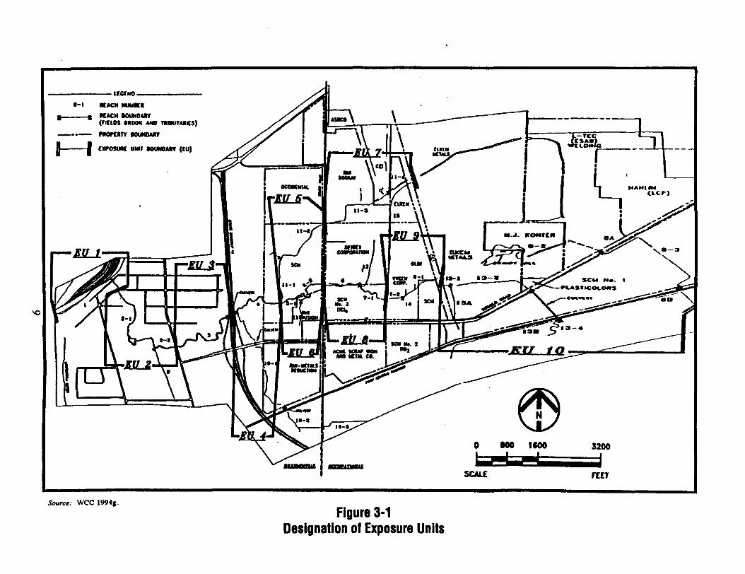
I———I cxfosuw UMIF MUMuunr (ru)
Source: WCC 1994g.Figure 3-1
Designation of Exposure Units

I SampleLocation! SBOliQ9^lM DRAFT
Sample LbctUoa
BBR iSample Location
"
SEOllCWS-H
SEOUWD.J
IBOmg/kt
Sample LocationField ID
M/7.0SA1GSO
Sample LocationField ID
1-1/8.1SA1HS1
Sample LocationField ID
1-1/9.2SA1IS2
I Sample Location | SEOU04S-U |
Sample LocationField IDTout PCBs
1-1/6.0SA1FSO5 JO mg/kg
Sample LocationField IDTotal PCBsSample LocatiooField IDTotal PCB*
1-1/ZOSA1BSOM.O tup/kg
1-1/10SA1BDO8.40 ing/kg
Sample LocationField IDTotal PCBs
1-1/0.2SA1QS213.0 mg/kg
Sample LocationField IDTotal PCBs
1-1/0.1SA1QS110.00 mg/kg
- N -
^Sample LocationField ID
1-1/10.1SAUS1
J Sample Location | SGQ1IUS-I1
Sample LocationField IDTotal PCBs
1-1/9.1SA1IS13.20 mg/kf{
Aibubuli Rlvei
Sample LocationField IDTotal PCBs
1-1/7.1SA1GS11.90 mft/kft
Sample LocationField IDTotal PCBs
1-1/6.1SA1FS11.90 mg/kg
BERVtU
5EQ110UD,ij i'i -:***:
Sample LocationField IDTotal PCBs
1-1/5.0SA1ESO12.0 mpAft
Ssmple LocationField IDTotal PCBs
1-1/1.1SA1QS3130mR/kg
Sample LocationField IDTotal PCBs
1-1/3.0SA1CSO1.50 mg/kg
• Simple: Ph*w | Stream Sedlmenl^ Sample: Phase II Stream Scdimeot
Woodward-Clyde Consultants
Note: Samples without posted results lodlcale thai compoundswen not detected la excess of USEPA 11/01/93 dean Up Goals,Shading Indicates sample* collected during Phase 1.1,
200 400 600 800
Source: WCC I994f. Figure 3-2Compounds Detected at Levels Greater ThanEPA11/93 Cleanup Goals In Exposure Unit 1

DRAFTN -
SimpleLocation
Sample Loculloa1"^
HEXACHLOROBTOTAL rceBBRYUJUM
StmpU Location ISE02108S-12
TOFALrCB ., U.O mg/kg '
SjoipU Loctttot-
Note: Staples without posted results Indicate that compoundswen not detected in exceu of USBPA 11/01/93 Clew Up Goals.Shading Indicates samples collected during Phase I.
Sample: Phase I Stream Sediment
Woodward-Clyde Consultantsn (Mo = 55on)
500 1000 1500
Source: WCC I994g. Figure 3-3Compounds Detected at Levels Greater ThanEPA11/93 Cleanup Goals in Exposure Unit 2
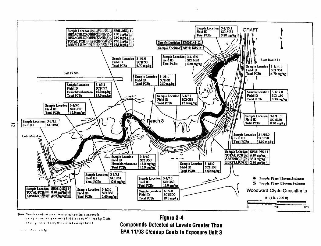
Simple LocationField IDTotal PCDs
3-1/13.1SC1MS13.80 ing/kg
DRAFT
•N -Sample Lbcatioa I SB03114S.U1
I Simple Loc»tioQ ISE031141?!
Sample LocationField ID
Sample LocationField IDTotal PCBs
3-1/12.0SC1LSO3.30 mg/kg
Sample LocatioaField IDTotal PCBs
3-i/ll.OSC1KSO8.20 rog/kg
3-1/10.0SCUSO2.50mgAg|
Sample LocationField IDTotal PCBs
Simple: Phase 1 Stream SedimentSample: Phase II Strum Sediment
Woodward-Clyde Consultants
Notf S«mplr» without potird rriulb loJIcalc thai comnouodl* f , f o i .J ru ti ID r».rvi i.ntMi'A II ni 'JU'lran Up C M!S. Figure 3-4
Compounds Detected at Levels Greater ThanEPA11/93 Cleanup Goals in Exposure Unit 3
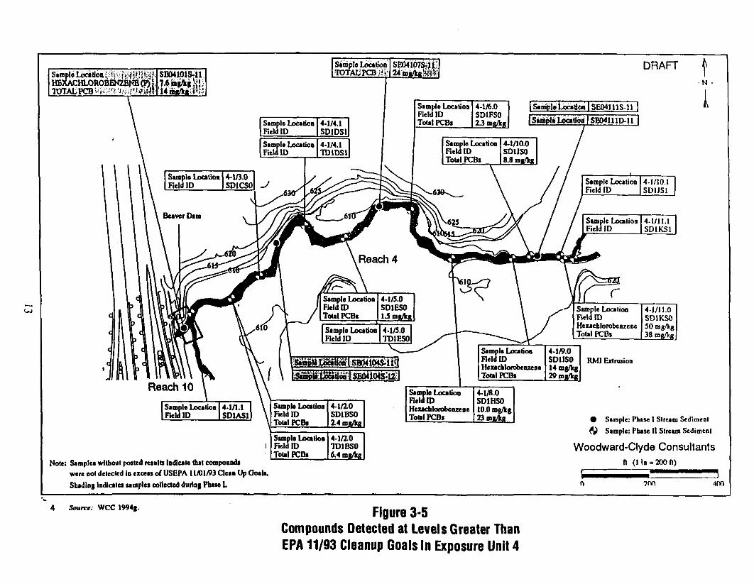
Sample Location £;ir^HBXACHLOROBENZBNB (F)TOTAL PCB l^£r* '
Simple LocationTOTAIJPCB^
DRAFTN -
Sample LocationField IDSample LocationField ID
4-1/4.1SD1DS14-1/4.1TO1DS1
Sample LocationField IDTotal PCBs
4-1/6.0SD1FSO2.3 mg/lcg
[Sentpte Location | SE04111S-11top!* Location |
Sample LocationField ID
4-1/10.1SD1JS1
Sample LocationField ID
4-1/11.1SDIKS1
rSample LocationField IDHexacblorobenze neTotal PCBs
4-1/11.0SD1KSOSOmg/kg
Sample LocationField ID
4-1/1.1SD1AS1
Note: Samples without posted results Indicate thai compoundjwere aol detected lo excess of USEPA 11/01/93 Clean Up Goals.Shading Indicates samples collected during Phase 1.
Sample LocationField IDTotal PCBs
Sample LocationField IDTotal PCDs
4-1/10SD1BSO2.4mg/kg
4-1/2.0TD1BSO6.4mg/kg
Sample LocationField IDHexachlorobenzeneTotal PCBs
Total KJH
4-1/8.0SDIHSO10.0 mg/kg23mg/kft
Sample LocationField IDHexachlorobenzeneTotal PCDs
4-1/9.0SD11SO14mg/kg29mg/kg
RMI Extrusion
• Sample: Phase 1 Stream Sediment^ Sample: Phase II Stream Sediment
Woodward-Clyde Consultantsn (i (0=1200 n)
?nn
4 Source: WCC 1994f. Figure 3*5Compounds Detected at Levels Greater ThanEPA 11/93 Cleanup Goals In Exposure Unit 4

Sample LocationField ID
11-2/7.0SK2GSO
Stale Road DRAFT
Sample Location I^!|l^-^c>:-lIEXACHiORODENZENBCFV
Sample LocationField ID1.1.Z2-TETRACHLOROETKANBTHTRACHLOROBTHENB•nUCHLOROEIHENBHexachlorobenzene
11-2/4.0SK2DSO1300 mg/kg1400 mg/kg1600 mg/kg160 mg/kg
Sample LocationField IDHexschlorobenzciM
11-2/11SK2BS11S.O mg/kg
Occidental Chemical Corporation
Ssnplb Location I SE1U02S.U ISample IJocatloo | SB 111023-12
Sample LocationField IDTETOACHLOROETHENBI lexachlorobenzeiM
11-2/7.1SK2GS1220 mg/kg32.0 mg/kg
N -
RMI Titanium Company Sodium
HEXACHLOROBENZENB (P)HEXACHLOROBENZBNB (S)
• -HEXACH£JOROBENZ1BNB (P) ,HEXACHlJDnOBENZENE (S)4
SE11206S.117.80 mg/kg10.00 cog/kgSBU2Q8D-U6.70 rag/kg9.50 ing/kg
Sample LocationField IDHexachlorobenze oe
11-2/6.0SK2FSO40.0 mg/kg
Sample LocationField IDUAi-TBTRACHLOROETHANETETOACHLOROBTHENESample LocationField ID
11-2/4.1SK2DSI1000 mg/kg430 mg/kg11-2/4.1SK2DD1490 mg/kg
Sample Location %&:UEXACHLOROBEN2ENB (P)J.HEXACHLOROBENZENB (SW
Sample LocationField IDHexachlorobeuzene
Sample LocationField IDHexachlorobenzeneARSENIC
11-2/3.0SK2CSO10.00 mg/kg30.0 mg/kg
Sample LocationField IDHeuchlorobenzene
11-2/2.0SK2BSO17.0 mg/kjt
Hole: Samples wilhoul posted results Indicate thsl compoundswere not detected In excess of USEPA 11/01/93 Clean Up Goals.Shading Indicates samples collected during Phase 1,
Sample LocationHeld IDTotal PCDs
11-1/1.0SK1ASO7.50 mjt/kg
• Sample: Phase I Stream Sediment& Sample: Phase 11 Stream Sediment
Woodward-Clyde Consultantsn (Ho* 4500)
innn
5 Source: WCC 1994g. Figure 3-6Compounds Detected at Levels Greater ThanEPA 11/93 Cleanup Goals in Exposure Unit 5

Simple Localioafield IDTotil PCBi
Simple LocalioaHeld IDTCTRACI ILOROEnffiNETotal PCBi
5-2/11.1SE2KS13 1.0 tun/kg52/11.1TE2KS1ZOOmgAg28.0 mg/kg
I Sample Location | SGD52125-11'SB05212S-12
Simple LocitiooHeld ID1.1,2,2-THniACHLOROCTHANB
5-2/8.1SE2MS1M.Omg/kR
Simple LocttloaField ID1,1,2,2-TffraACHLOROBniANBTBTRACHLOROETI ffiNHSimple LoalioaField ID1,1,2^-TBrRACHLOROHTHANBTBIKACHLOROBTlIBIt:HexichlorobeBzeaeToUlPCBs
Simple LocatioDField IDTETRACHLOROETHENBHexacbtorobcttcoeToUl FCBs
5-1/3.0SE1CSO200 mg/kg7.90 tag/kg15.0 ng/kg
Simple Loeado*TOTAL PCBARSENIC ;
BBRYLUUM!
Simple Ltxatioo ;TimuaDjOROBTHBHn iTOTAL PCB i
Simple LoctdooHeld IDHexichlofobeueMTol.l PCBt
5-2/3.1SE2CS16.80 mg/kg14.0 Dg/kg
Note: Simple* wllhoul posted results lodicale thai compouadiwere DO! detected la excess of USGPA 11/01/93 Cteia Up OotU.Shading iodicales cimples collected during PbiM I.
Simple LocilloaField IDToUl PCBs
5-2/5.0SE2ESO3.00 mg/kg
Simple Lociilot I SB052Q4S.il!
Simple LocattoaField IDTBTRAClILOROim ffiNETRICHLOROEHIENBI leiichlofobeazeneToUl PCBi
5-2/3.2SE2CS24400 mg/kg1100 mg/kg150 mg/kg93.0 rng/kg
5-2/12.2SE2LS2550 mg/kg460 mg/kg
DRAFTN -
5-2/12.2TE2LS24800 mg/kg6600 mg/kg48.0 mg/kg
Detiei CoipontioBSimple Location 'BENZO(A)FYRENBTOTAL FCP>--^-';
SE05214S-I11.24.0 gift/kg
Simple lxfcail6THIRACHLOROBTHENE
SE05214S-12530iog/kg '
SCMPI»l2-Tia4
RMI Titanlitm Cocupiojr Eilrusioi
Simple Loci lionHeld ID
5-2/10.1SE2JS1
Simple LociiioaField IDTotal PCBs
5-2/10.0SE2JSO2.80 mft/kft
SED5209S-117.°Qrog/kg
| Simple Location I SBD52Q9S-12 |
• Sample: Phase 1 Stream Sediment(V Sample: Phase II Stream Sediment
Woodward-Clyde Consultants
ism
6 Source: WCC 1994f. Figure 3-7Compounds Detected at Levels Greater ThanEPA11/93 Cleanup Goals in Exposure Unit 6

DRAFT
Stale Road
Sample LocationField IDARSENICSample LocationField IDARSENIC
\\3/5.0JESOOmo/kfl
11-4/13SK4AS3180 mg/kg
1M/I.3SK4AD378.7 me/kg\
Sample LocationARSBNKMItiBBRYLUUM^
Sample LocationField IDARSENIC
IM/i.4SK4AS4I29mR/kg
Sample LocationField IDARSENIC
RMI Titanium Company Sodium
Sample LocationField IDARSENIC
Simple LocationField IDARSENIC
Sample LocationField IDARSENIC
1M/1.2SK4AS244.3 mg/kg\\11-4/1.1SK4AS1106 me/kg
Simple Location ISB11401S-11 |
Sample Location | SE11306S-UJiimpl* Location | SBU306S-12~
Vygeo
Sample LocationField ID
11-3/1.1SK3AS1
Sample LocatiooField ID1,1,2,2-TC-raACHLOROEIHANBTBTTIACHLOROETHENBTOICHLOROETIIENBHexacblorobenzene
11-3/2.1SK3BS12100 rug/kg1800 mg/kg4100 nag/kg34.0 mg/kg
Note: Samples without posted results Indicate thai compound*were detected in excess of USEPA11 fll/93 Clean Up Goals.Shading indicates samples collected daring Phase I.
Detrex Corporation
• Sample: Phase I Stream Sediment^ Sample: Phase [1 Stream Sediment
Woodward-Clyde Consultants________n ( I l n = t 3 3 0 n )
300 1000
7 Sount: WCC I994g. Figure 3-8Compounds Detected at Levels Greater ThanEPA11/93 Cleanup Goals in Exposure Unit 7

Simple LocalJob" i^i-HEXACHLOROBENZENB (P)HEXACHLORQBENZfiHB (S)
Sample Location I SE06101S.U 48.0mg/Vg30.0nSample' Location I;V!.<>
1.1,12-TE'mACHLOROffniANB Sample Location Sample Locadoo I SBQ6itOS.il35000 mg/kgi5000mg/Jtg Reach 12 (Detrex Tributiiy)
Simple UbcaNoD ISE07108S-11a: 156071065-12
Note: Simples without ponied results Indicate that coraponodswen ool detected ID excess of USEPA 11 AH/93 Cleu Up Goals.Shading indicates samples collected during Phase 1.
Sample: Phase I Stream SedimentSample: Phase II Stream Sediment 200 400 600
8 Sourct WCC }994g Figure 3-9Compounds Detected at Levels Greater ThanEPA11/93 Cleanup Goals in Exposure Unit 8

Former TDI Facility DRAFT
Vygent
Sample LocationField ID
8-1/5.0SHtESO
Sample LocationHeld ID
8-1/7.2SH1GS2
N -
Sample LocationField ID
8-1/11SH1BS1
Sample LocationField IDi —— - — , — , — __j
8-1/3.2SH1CS2
ISample LocationField ID
8-1/7.1SI11GS1
DeUex Corporation
Sample LocationField ID
8-1/2.0SH1BSO
Reach 7-1
SCM Plant 2 - TiCH
I Sample Location
Sample Location
Simple LocaHoa | 5B072Qi&-H||
Sample Local!Field ID
I Sample Location
Simple Location ISB08103S4HIple LocationSample Location 7-2/2.0
Field ID I SO2BSOI
Note: Samples wilboul posted results lodlcale that compoundswere ool detected lo excess of USEPA 11/01/93 Clean Up Gals.Shading Indicates samples collected during Phase I.
Simple: Phase I Stream SedimentSample: Phase II Stream Sediment
Woodward-Clyde ConsultantsA (1 In = 2000)
200IlJ400
9 Source: WCC 1994g. Figure 3-10Compounds Detected at Levels Greater ThanEPA11/93 Cleanup Goals in Exposure Unit 9

DRAFTI Simple tbcario* I SBU201S-U I
I Simplfl Location j 56132015 12LocaUop I SBl3201D^2
Sample Location 1SB083Q2S-USanrola Lbcalion I SE082Q3S'12
Simple Location 8-3/2.2
Reach 8-3
Simple Loatfoo | SBUtOlS-iM
Sunpl»Lo<aHoa ISBI3101S-12 Reach 13-2
Reach 13-1"I Sample Location | SE08303S-1I- - * • * - • • » • ^- - X/-' Yx/V-^i
Sample LocatioD 13-2/1.3 I '\&/^t&i?Field ID SM2AD3IX JfiS^III^T————^————"^^ ^giS^^ /'
Simple Location ISEC83Q3D-11^ ——Reach 13-A V
Sample Lo^rioti 5Ei3202&lField ID SM2AS1Sample Loci lion 13-2/1.1 Simple: Phase I Stream Sediment
Sample: Phase II Stream Sediment
ft
Field ID SM2AS2Sample Locitioo 13-2/1.2Field ID SM5AS1
Sample Location 13-A/1.1
Simple Location SBl3l02S-lii
Simple Loatioo SBl3102D-lliARSEHIGjjr^U "
I Sample Loallon | SB13102S-12;
I Stmple LtKatioo | SEl3AfllS.H=|I Sample LoCiUott I SB13AOls52
3B13A025-11
500 1000 1500
Nole: Samples without posted results Indicate thai compound* _.were nol detecled in excess of USEPA 1IA)1#3 Clean Up Goals. PlQUfC 3"11
5^ Stdci^wdi,riim'>lacollededdllrillgI>hlMl' Compounds Detected at Levels Greater Than
EPA11/93 Cleanup Goals in Exposure Unit 10

Table 3-2Summary of Removal Volumes
Exposureunit*
EU1EU2EU2EU3EU4EU5EU5EU6EU6EU7EU7EU8EU8EU9EU9
EU10EU10EU10EU10EU10EU10EU10
Streamreachb
12-lc
2-2c
34
11-111-25-15-211-311-46
7-17-28-113-113-213A8-28-38-48A
SubtotalVolumeestimate
Thermaltreatment
000000
1651,3121,302
300
3560000000000
3,166
3,000
Volume estimates (yd3)
Solidification
8142,2871,0741,193
95618578
331163
0810
00000000000
7,889
8,000
No treatment
7803,270
290950
1,710200840
1,1002,4701,840
2302,140
0000000000
15,820
16,000
'See Figure 2-4 for exposure unit locations.bSee Figure 2-3 for stream reach locations."Includes total excavation of EU2.
A241.F20

Table 3-3Grouping of Reaches into Exposure Units
SQDI Field Sampling PlanSediment Operable Unit - Fields Brook Site, Ashtabula, Ohio
Grouping of Reaches into Exposure Unitsfor Which Cleanup Decisions are Made
Exposure Unit 1
Exposure Unit 2
Exposure Unit 3
Exposure Unit 4
Exposure Unit 5
Exposure Unit 6 •
Exposure Unit 7
Exposure Unit 8
Exposure Unit 9
Exposure Unit 10
Reach 1
Reaches 2-1 and 2-2, portion of 9
Reach 3
Reach 4
Reaches 11-1 and 11-2
Reaches 5-1 and 5-2
Reaches 11-3 and 11-4
Reaches 6 and 7-1
Reaches 7-2 and 8-1
Reaches 8-2, 8-3, 8A, 13-1, 13-2, and 13A
Residential
Residential
Residential
Residential
Residential
Residential
Occupational
Occupational
Occupational
Occupational
Note that Reaches 10-1, 10-2, 10-3, 10-4, 12, 15, and most of 9 have been eliminated fromconsideration for remediation
A24I.F2/17/95 4:llpm
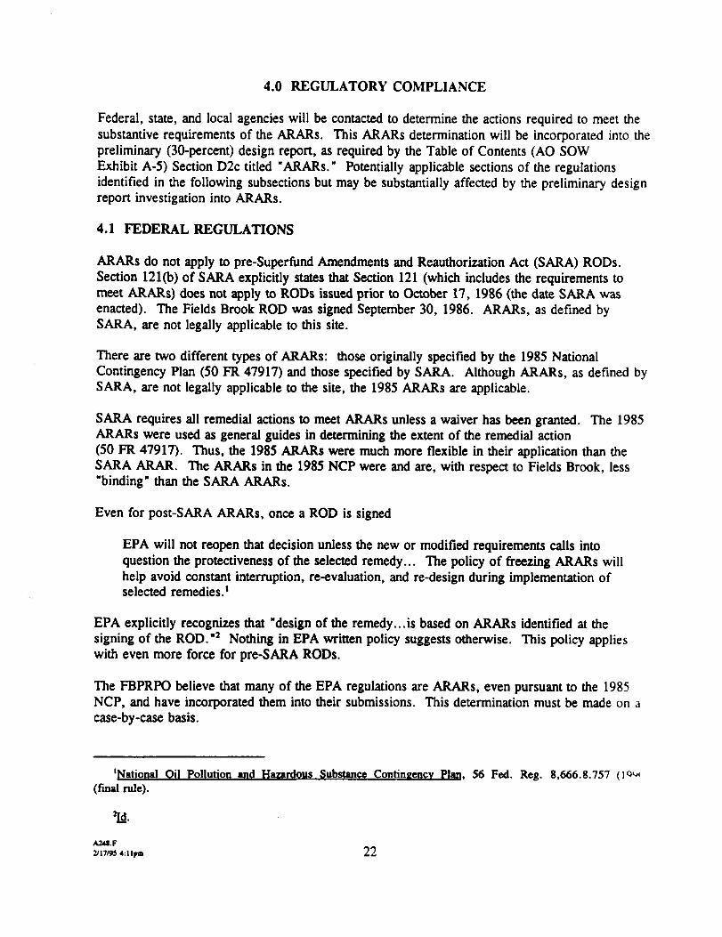
4.0 REGULATORY COMPLIANCE
Federal, state, and local agencies will be contacted to determine the actions required to meet thesubstantive requirements of the ARARs. This ARARs determination will be incorporated into thepreliminary (30-percent) design report, as required by the Table of Contents (AO SOWExhibit A-5) Section D2c titled " ARARs." Potentially applicable sections of the regulationsidentified in the following subsections but may be substantially affected by the preliminary designreport investigation into ARARs.
4.1 FEDERAL REGULATIONS
ARARs do not apply to pre-Superfimd Amendments and Reauthorization Act (SARA) RODs.Section 121(b) of SARA explicitly states that Section 121 (which includes the requirements tomeet ARARs) does not apply to RODs issued prior to October 17, 1986 (the date SARA wasenacted). The Fields Brook ROD was signed September 30, 1986. ARARs, as defined bySARA, are not legally applicable to this site.
There are two different types of ARARs: those originally specified by the 1985 NationalContingency Plan (50 FR 47917) and those specified by SARA. Although ARARs, as defined bySARA, are not legally applicable to the site, the 1985 ARARs are applicable.
SARA requires all remedial actions to meet ARARs unless a waiver has been granted. The 1985ARARs were used as general guides in determining the extent of the remedial action(50 FR 47917). Thus, the 1985 ARARs were much more flexible in their application than theSARA ARAR. The ARARs in the 1985 NCP were and are, with respect to Fields Brook, less"binding" than the SARA ARARs.
Even for post-SARA ARARs, once a ROD is signed
EPA will not reopen that decision unless the new or modified requirements calls intoquestion the protectiveness of the selected remedy... The policy of freezing ARARs willhelp avoid constant interruption, re-evaluation, and re-design during implementation ofselected remedies.1
EPA explicitly recognizes that "design of the remedy...is based on ARARs identified at thesigning of the ROD."2 Nothing in EPA written policy suggests otherwise. This policy applieswith even more force for pre-SARA RODs.
The FBPRPO believe that many of the EPA regulations are ARARs, even pursuant to the 1985NCP, and have incorporated them into their submissions. This determination must be made on acase-by-case basis.
'National Oil Pollution and Substance Contingency Plan. 56 Fed. Reg. 8,666.8.757(final rule).
Id.
A24I.F2/17/95 4:llptD 22

The following is a list of potential ARARs based on the 1985 NCP, which will be refined in thePreliminary Design Report.
4.1.1 Resource Conservation and Recovery Act
Reference
40 CFR 264
40 CFR 260.22
40 CFR40 CFR40 CFR40 CFR40 CFR40 CFR40 CFR40 CFR40 CFR40 CFR40 CFR40 CFR40 CFR
261262264.50-56264.110-120264.142264.147268270.15270.16270.18270.19270.21270.62
Description
Standards for Owners and Operators of Hazardous WasteTreatment, Storage, and Disposal Facilities:Subpart A - GeneralSubpart B - General Facility StandardsSubpart C - Preparedness and PreventionSubpart D - Contingency Plan and Emergency ProceduresSubpart E - Manifest System, Recordkeeping, and ReportingSubpart F - Procedures to Prevent HazardsSubpart G - Closure and Post-ClosureSubpart H - Financial RequirementsSubpart I - Use and Management of ContainersSubpart J - Tank SystemsSubpart K - Waste PilesSubpart M - Land TreatmentSubpart N - LandfillsSubpart O - Hazardous Waste IncineratorsSubpart X - Hazardous Waste Miscellaneous UnitsPetitions to Amend Part 261 to Exclude a Waste Produced at aParticular FacilityIdentification of Hazardous WasteHazardous Waste Generator Permit and EPA ID NumberContingency PlanClosure PlanCost Estimate for ClosureLiability RequirementsLand Disposal RestrictionsInformation Required for ContainersInformation Requirements for Tank SystemsInformation Requirements for Waste PilesInformation Requirements for IncineratorsInformation Requirements for Land FillsTrial Burn Plan
4.1.2 Occupational Safety and Health Administration (OSHA)
29 CFR 1904 Recordkeeping, Reporting, and Related Regulations29 CFR 1910 General Industry Standards29 CFR 1914 Log and Summary of Occupational Injuries and Illnesses29 CFR 1926 General Construction Standards
A24I.F2/17/95 4:llpn 23

4.1.3 Clean Air Act
• National Emission Standards for Hazardous Air Pollutants and its implementing regulations,40 CFR 61
• Air Emission Permits
4.1.4 Executive Orders
• Executive Order 11990, Protection of Wetlands, and its implementing regulations, 44 CFR 9• Executive Order 11988, Floodplain Management, and its implementing regulations, 44 CFR 9
4.1.5 Clean Water Act
• National Pollutant Discharge Elimination System (NPDES) regulations, 40 CFR 122-125• Section 404, Dredge and Fill Activities, and its implementing regulations, 33 CFR 323• U.S. Army Corps of Engineers regulations, 33 CFR 320, 322, 328-330
4.1.6 CERCLA
40 CFR 300 National Contingency Plan
4.1.7 Toxic Substances Control Act (TSCA)
40 CFR 761 Implementing Regulations for PCBs
4.1.8 ARARs for Dewatering and Excavation
The potential ARARs considered for the siting, design, construction, and operation of thesediment dewatering units and for excavation are summarized as follows.
Occupational Safety and Health Regulations (29 CFR 1910 and 1926)
The Occupational Safety and Health Administration (OSHA) has promulgated a comprehensiveset of occupational safety and health standards. These regulations take a two-pronged approachto worker safety by establishing safe working practices and safe levels of exposure to a variety ofmaterials. These regulations will apply during the remedial activities.
Clean Water Act, National Pollutant Discharge Elimination System(40 CFR 122, 125, 129, and 133)
These regulations control point-source discharges to waters of the United States. Theseregulations require the use of the best available technology that is economically achievable tocontrol toxic and nonconventional pollutants and the use of the best conventional pollutant controltechnology to control conventional pollutants. Technology-based limitations may be determinedon a case-by-case basis. Water-quality-based effluent limitations are based on state narrative andnumeric water quality criteria, which depend on the type of stream and type of pollutants
A24I.F2/17/95 4:llpm 24

discharged to the stream. Best management practices to control toxic discharges must also beconsidered.
These regulations are potentially applicable if treated wastewater is discharged from the site toFields Brook or the Ashtabula River.
Clean Water Act, EPA Pretreatment Standards(40 CFR 403) (40 CFR 122, 125, 129, and 133)
These requirements regulate the industrial discharges to a POTW. They prohibit introduction ofpollutants to a POTW that "pass-through" (i.e., exit the POTW in quantities or concentrationsthat violate the POTW's NPDES permit) or cause "interference" (i.e., inhibit or disrupt thePOTW, or its treatment processes or operations, or its sludge processes, use, or disposal, therebycausing a violation of the NPDES permit). These standards also prohibit the following fromentering a POTW:
• Pollutants that create a fire or explosion hazard including, but not limited to, waste streamswith a closed cup flashpoint of less than 140PF or 60°C using the test methods specified in 40CFR 261.21
• Pollutants that will cause corrosive structural damage
• Solid or viscous pollutants that will obstruct flow, that are discharged at a flow rate and/orconcentration that will cause interference, and/or that will harm sanitation workers
• Heat that will inhibit biological activity
• Petroleum oil, nonbiodegradable cutting oil, or products of mineral oil origin in amounts thatwill cause interference or pass through
• Pollutants that will result in the presence of toxic gases, vapors, or fumes within the POTW ina quantity that may cause acute worker health and safety problems
• Any trucked or hauled pollutants, except at discharge points designated by the POTW
These regulations would be applicable if treated wastewater from the site is discharged to thelocal POTW.
Safe Drinking Water Act (40 CFR 141 and 143)
The Safe Drinking Water Act establishes primary drinking water quality standards to protecthuman health and secondary water quality standards to ensure the aesthetic quality of drinkingwater. These standards are referred to as maximum contaminant levels (MCLs). For water thatis to be used for drinking, the MCLs are generally ARARs. MCLs are applicable where thewater will be provided directly to 25 or more people or will be supplied to 15 or more serviceconnections. If MCLs are applicable, they are applied at the tap. In addition, MCLs are
A24IF **•2/17/95 4:l)poi 25

relevant and appropriate as in situ cleanup standards where either surface water or groundwater isor may be used for drinking water.
If the treated wastewater from the site is discharged to Fields Brook or the Ashtabula River andeither of those bodies-of water is used for drinking water, MCLs will be considered relevant andappropriate for site remediation.
Ohio NPDES Program (OAC 3745-33-01)
These rules regulate point-source discharges to state waters. These discharges must comply withapplicable water quality standards and applicable effluent limitations (i.e., national effluentlimitations, national standards for new sources, and national toxic and pretreatment effluentlimitations).
Ohio Water Quality Standards (ORC Chapter 3745-1)
These regulations define ambient surface water quality criteria. Fields Brook must meet thenarrative and numerical water quality standards. Fields Brook is designated as a limitedwarm-water aquatic habitat, agricultural and industrial water supply, and primary contact forrecreation (3654-1-14). Warm-water criteria are used for limited warm-water streams.However, individual criteria for limited warm-water streams may vary and may supersede thecriteria for warm-water habitat.
These regulations will be applicable if wastewater from the site is discharged to Fields Brook.
Ohio Drinking Water Regulations (OAC Title 3745, Chapters 81 and 82)
The Ohio primary and secondary drinking water standards are the same as the national drinkingwater standards, except that the pH is set at 7.0 to 10.5.
If the treated wastewater from the site is discharged to Fields Brook or the Ashtabula River andeither of those bodies of water is used for drinking water, the Ohio primary or secondarydrinking water standards will be considered relevant and appropriate for site remediation.
Ohio Hazardous Waste Generator Standards (OAC Title 3745, Chapter 52)
These regulations specify standards for owners/operators of facilities where hazardous waste isgenerated. These requirements include standards for the storage of hazardous waste, the need tomanifest waste shipped offsite, and pretransport requirements.
Ohio Hazardous Waste Management (OAC Title 3745, Chapter 55)
These regulations regulate the treatment and storage of hazardous waste. If hazardous waste isstored onsite, it must be stored in compliance with the regulations for containers, tanks, surfaceimpoundments, or waste piles. These regulations also specify the design and operating standardsthat must be met for the treatment of hazardous
A248.F2/17/95 4: llpm

RCRA Hazardous Waste Generator Standards (40 CFR 262)
These regulations stipulate requirements for owners/operators who generate hazardous waste.Requirements include procedures for identifying/classifying hazardous waste, design andoperating standards for the storage of hazardous waste, and manifest procedures for offsiteshipment of waste.
RCRA Storage Requirements (40 CFR 264)
These regulations define the design and operating standards for units that are used to store ortreat hazardous waste. If hazardous wastes are to be stored onsite, the storage area must complywith the regulations for containers (Subpart I) or tanks (Subpart J). Design and operatingstandards for treatment of hazardous waste in a unit are as follows: tanks (40 CFR 264.190-192), surface impoundments (40 CFR 264.221), incinerators (40 CFR 264.343-345), andmiscellaneous units (40 CFR 264.601).
4.1.9 ARARs for Water Treatment
Potential ARARs considered for the siting, design, construction, and operation of the watertreatment units are summarized below.
Occupational Safety and Health Regulations (29 CFR 1910 and 1926)
OSHA has promulgated a comprehensive set of occupational safety and health standards. Theseregulations take a two-pronged approach to worker safety by establishing safe working practicesand safe levels of exposure to a variety of materials. These regulations will apply during theremedial activities.
Clean Water Act, National Pollutant Discharge Elimination System(40 CFR 122, 125, 129, and 133)
These regulations control point-source discharges to waters of the United States. Theseregulations require the use of the best available technology that is economically achievable tocontrol toxic and nonconventional pollutants and the use of the best conventional pollutant controltechnology to control conventional pollutants. Technology-based limitations may be determinedon a case-by-case basis. Water-quality-based effluent limitations are based on state narrative andnumerical water quality criteria, which depend on type of stream and type of pollutantsdischarged to the stream. Best management practices to control toxic discharges must also beconsidered.
These regulations are potentially applicable if treated wastewater is discharged from the site toFields Brook or the Ashtabula River.
Safe Drinking Water Act (40 CFR 141 and 143)
The Safe Drinking Water Act establishes primary drinking water quality standards to protecthuman health and secondary water quality standards to ensure the aesthetic quality of drinking
A24«.F2/17/95 4:llpn 27
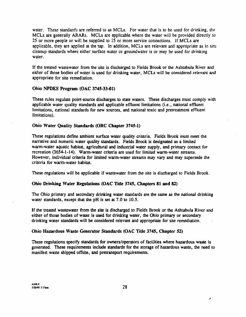
water. These standards are referred to as MCLs. For water that is to be used for drinking, theMCLs are generally ARARs. MCLs are applicable where the water will be provided directly to25 or more people or wil! be supplied to 15 or more service connections. If MCLs areapplicable, they are applied at the tap. In addition, MCLs are relevant and appropriate as in situcleanup standards where either surface water or groundwater is or may be used for drinkingwater.
If the treated wastewater from the site is discharged to Fields Brook or the Ashtabula River andeither of those bodies of water is used for drinking water, MCLs will be considered relevant andappropriate for site remediation.
Ohio NPDES Program (OAC 3745-33-01)
These rules regulate point-source discharges to state waters. These discharges must comply withapplicable water quality standards and applicable effluent limitations (i.e., national effluentlimitations, national standards for new sources, and national toxic and pretreatment effluentlimitations).
Ohio Water Quality Standards (ORC Chapter 3745-1)
These regulations define ambient surface water quality criteria. Fields Brook must meet thenarrative and numeric water quality standards. Fields Brook is designated as a limitedwarm-water aquatic habitat, agricultural and industrial water supply, and primary contact forrecreation (3654-1-14). Warm-water criteria are used for limited warm-water streams.However, individual criteria for limited warm-water streams may vary and may supersede thecriteria for warm-water habitat.
These regulations will be applicable if wastewater from the site is discharged to Fields Brook.
Ohio Drinking Water Regulations (OAC Tide 3745, Chapters 81 and 82)
The Ohio primary and secondary drinking water standards are the same as the national drinkingwater standards, except that the pH is set at 7.0 to 10.5.
If the treated wastewater from the site is discharged to Fields Brook or the Ashtabula River andeither of those bodies of water is used for drinking water, the Ohio primary or secondarydrinking water standards will be considered relevant and appropriate for site remediation.
Ohio Hazardous Waste Generator Standards (OAC Title 3745, Chapter 52)
These regulations specify standards for owners/operators of facilities where hazardous waste isgenerated. These requirements include standards for the storage of hazardous waste, the need tomanifest waste shipped off site, and pretransport requirements.
-2/20/95 2:17pm 28
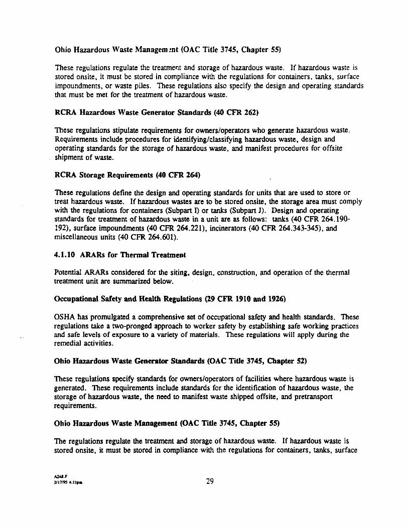
Ohio Hazardous Waste Management (OAC Title 3745, Chapter 55)
These regulations regulate the treatment and storage of hazardous waste. If hazardous waste isstored onsite, it must be stored in compliance with the regulations for containers, tanks, surfaceimpoundments, or waste piles. These regulations also specify the design and operating standardsthat must be met for the treatment of hazardous waste.
RCRA Hazardous Waste Generator Standards (40 CFR 262)
These regulations stipulate requirements for owners/operators who generate hazardous waste.Requirements include procedures for identifying/classifying hazardous waste, design andoperating standards for the storage of hazardous waste, and manifest procedures for offsiteshipment of waste.
RCRA Storage Requirements (40 CFR 264)
These regulations define the design and operating standards for units that are used to store ortreat hazardous waste. If hazardous wastes are to be stored onsite, the storage area must complywith the regulations for containers (Subpart I) or tanks (Subpart J). Design and operatingstandards for treatment of hazardous waste in a unit are as follows: tanks (40 CFR 264.190-192), surface impoundments (40 CFR 264.221), incinerators (40 CFR 264.343-345), andmiscellaneous units (40 CFR 264.601).
4.1.10 ARARs for Thermal Treatment
Potential ARARs considered for the siting, design, construction, and operation of the thermaltreatment unit are summarized below.
Occupational Safety and Health Regulations (29 CFR 1910 and 1926)
OSHA has promulgated a comprehensive set of occupational safety and health standards. Theseregulations take a two-pronged approach to worker safety by establishing safe working practicesand safe levels of exposure to a variety of materials. These regulations will apply during theremedial activities.
Ohio Hazardous Waste Generator Standards (OAC Title 3745, Chapter 52)
These regulations specify standards for owners/operators of facilities where hazardous waste isgenerated. These requirements include standards for the identification of hazardous waste, thestorage of hazardous waste, the need to manifest waste shipped offsite, and pretransportrequirements.
Ohio Hazardous Waste Management (OAC Title 3745, Chapter 55)
The regulations regulate the treatment and storage of hazardous waste. If hazardous waste isstored onsite, it must be stored in compliance with the regulations for containers, tanks, surface
A24I.F2/17/95 4:llpm 29

impoundments, or waste piles. These regulations also specify the design and operating standardsthat must be met for the treatment of hazardous waste.
Ohio Land Disposal Restrictions (OAC Title 3745, Chapter 59)
Because the Fields Brook ROD was signed before the enactment of SARA, the ARARs definedin the 1985 National Oil and Hazardous Substances Pollution Contingency Plan (NCP) apply tothe site. Those ARARs are used as general guides in determining the extent of the remedialaction (50 FR 47917). They are much more flexible in their application and are, in effect,nonbinding. Furthermore, when EPA promulgated the treatment standards for land disposalrestrictions, EPA recognized that treatment of waste, including contaminated soils, to thetreatment standards would not always be possible or appropriate (Superfund Publication9347.3-06FS, September 1990). Therefore, the application of the land disposal restrictions tosoils and sediments at this site is not required.
RCRA Hazardous Waste Generation Regulations (40 CFR 262)
Part 262 describes the regulatory requirements imposed on generators of hazardous waste. Theregulations address accumulating wastes without a permit, preparing waste for shipment, andusing the uniform hazardous waste manifest system. Obviously, each generator must also befamiliar with the contents of Pan 261, which explains how to identify a hazardous waste.
RCRA Standards for Owners/Operators of Hazardous Waste Treatment, Storage, andDisposal Facilities (40 CFR 264)
Part 264 standards impose stringent requirements on hazardous waste treatment, storage, anddisposal facilities (TSDFs). The regulations fall into two general classifications: (1) Subparts Athrough H are general standards applicable to these facilities; and (2) Subparts I through BBapply to specific types of treatment, storage, and disposal activities (i.e., the use of landfills,incinerators, tanks) or specific equipment (e.g., drip pads and process vents).
Subpart O addresses the facility standards for incinerators. Specifically, this subpart specifieshow an incinerator is to be designed, constructed, operated, and maintained. Hazardous wasteincinerators must comply with strict testing and performance standards.
Clean Air Act, National Primary and Secondary Ambient Air Quality Standards(40 CFR 50)
The National Ambient Air Quality Standards (NAAQS) specify the maximum concentration of afederally regulated air pollutant in an area resulting from all sources of that pollutant. No newconstruction or modification of a facility, structure, or installation may emit an amount of anycriteria pollutant that will interfere with the attainment or maintenance of an NAAQS.
A2W.F2/17/93 <:llpm 30

Clean Air Act, National Emission Standards for Hazardous Air Pollutants (40 CFR 61)
These standards regulate eight hazardous air pollutants [40 CFR 61.01 (a)] and list other airpollutants that cause serious health effects [40 CFR 61.01(b)J. These requirements could beapplicable if the thermal treatment results in the release of hazardous air pollutants.
Nonattainment Area Regulations (OAC 3745-31, 35)
These regulations require new or modified sources located in nonattainment areas to meet specialtechnology-based and air-quality-based requirements in addition to New Source PerformanceStandards. These requirements are referred to as the Lowest Achievable Emission Rate andoffsets. These regulations are potentially applicable because the Fields Brook site is in anonattainment area for ozone.
Toxic Substances Control Act (40 CFR Part 761)
The Toxic Substarices Control Act (TSCA) regulates the management, storage, and disposal ofPCBs. It provides requirements for the design and operation of units used for treatment, storage,and disposal of PCBs and PCB-contaminated items, such as soils or sediments. TSCAregulations specify that soils and sediments contaminated with PCBs at more than 50 mg/kg maybe disposed of at a TSCA incinerator, at a TSCA chemical waste landfill, or by a TSCA-approved alternative disposal method [40 CFR 761.60(a)(4)].
TSCA regulations also describe the design, construction, operating, and maintenance standardsfor an incinerator that treats PCBs and PCB-contaminated items. These standards are provided in40 CFR 761.70 and include provisions for the following criteria: combustion, combustionefficiency, feed rate, monitoring temperature, monitoring stack emissions, monitoring andrecording for combustion products and incineration operations, automatic cutoff systems, and useof water scrubbers for hydrogen chloride (HC1) control during incineration.
4.1.11 ARARs for Solidification
Potential ARARs considered for the siting, design, construction, and operation of thesolidification process is summarized as follows.
Occupational Safety and Health Regulations (29 CFR 1910 and 1926)
OSHA has promulgated a comprehensive set of occupational safety and health standards. Theseregulations take a two-pronged approach to worker safety by establishing safe working practicesand safe levels of exposure to a variety of materials These regulations will apply during theremedial activities.
A24S.F2/17/95 4:llpm
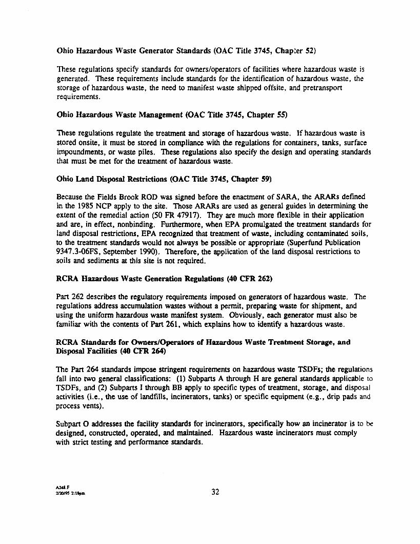
Ohio Hazardous Waste Generator Standards (OAC Title 3745, Chapter 52)
These regulations specify standards for owners/operators of facilities where hazardous waste isgenerated. These requirements include standards for the identification of hazardous waste, thestorage of hazardous waste, the need to manifest waste shipped offsite, and pretransportrequirements.
Ohio Hazardous Waste Management (OAC Title 3745, Chapter 55)
These regulations regulate the treatment and storage of hazardous waste. If hazardous waste isstored onsite, it must be stored in compliance with the regulations for containers, tanks, surfaceimpoundments, or waste piles. These regulations also specify the design and operating standardsthat must be met for the treatment of hazardous waste.
Ohio Land Disposal Restrictions (OAC Tide 3745, Chapter 59)
Because the Fields Brook ROD was signed before the enactment of SARA, the ARARs definedin the 1985 NCP apply to the site. Those ARARs are used as general guides in determining theextent of the remedial action (50 FR 47917). They are much more flexible in their applicationand are, in effect, nonbinding. Furthermore, when EPA promulgated the treatment standards forland disposal restrictions, EPA recognized that treatment of waste, including contaminated soils,to the treatment standards would not always be possible or appropriate (Superfund Publication9347.3-06FS, September 1990). Therefore, the application of the land disposal restrictions tosoils and sediments at this site is not required.
RCRA Hazardous Waste Generation Regulations (40 CFR 262)
Pan 262 describes the regulatory requirements imposed on generators of hazardous waste. Theregulations address accumulation wastes without a permit, preparing waste for shipment, andusing the uniform hazardous waste manifest system. Obviously, each generator must also befamiliar with the contents of Part 261, which explains how to identify a hazardous waste.
RCRA Standards for Owners/Operators of Hazardous Waste Treatment Storage, andDisposal Facilities (40 CFR 264)
The Pan 264 standards impose stringent requirements on hazardous waste TSDFs; the regulationsfall into two general classifications: (1) Subparts A through H are general standards applicable toTSDFs, and (2) Subparts I through BB apply to specific types of treatment, storage, and disposalactivities (i.e., the use of landfills, incinerators, tanks) or specific equipment (e.g., drip pads andprocess vents).
Subpart O addresses the facility standards for incinerators, specifically how an incinerator is to bedesigned, constructed, operated, and maintained. Hazardous waste incinerators must complywith strict testing and performance standards.
2/3V95 2: 18pm 32

Clear Air Act, National Primary and Secondary Ambient Air Quality Standards(40 CFR 50)
The NAAQS specify the maximum concentration of a federally regulated air pollutant in an arearesulting from all sources of that pollutant. No new construction or modification of a facility,structure, or installation may emit an amount of any criteria pollutant that will interfere with theattainment or maintenance of an NAAQS.
Clean Air Act, National Emission Standards for Hazardous Air Pollutants (40 CFR 61)
These standards regulate eight hazardous air pollutants [40 CFR 61.01 (a)] and list other airpollutants that cause serious health effects [40 CFR 61.01(b)]. These requirements could beapplicable if the thermal treatment results in the release of hazardous air pollutants.
Nonattainment Area Regulations (OAC 3745*31, 35)
These regulations require new or modified sources located in nonattainment areas to meet specialtechnology-based and air-quality-based requirements in addition to New Source PerformanceStandards. These requirements are referred to as Lowest Achievable Emission Rate and offsets.These regulations are potentially applicable because the Fields Brook site is in a nonattainmentarea for ozone.
4.1.12 ARARs for Facility Siting
Potential ARARs considered for the siting, design construction, and operation of the facility issummarized as follows.
Occupational Safety and Health Regulations (29 CFR 1910 and 1926)
OSHA has promulgated a comprehensive set of occupational safety and health standards. Theseregulations take a two-pronged approach to worker safety by establishing safe working practicesand safe levels of exposure to a variety of materials. These regulations will apply during theremedial activities.
Clean Water Act, National Pollutant Discharge Elimination System(40 CFR 122, 125, 129, and 133)
These regulations control point-source discharges to waters of the United States. Theseregulations require the use of the best available technology that is economically achievable tocontrol toxic and nonconventional pollutants and the use of the best conventional pollutant controltechnology to control conventional pollutants. Technology-based limitations may be determinedon a case-by-case basis. Water-quality-based effluent limitations are based on state narrative andnumeric water quality criteria, which depend on the type of stream and type of pollutantsdischarged to the stream. Best management practices to control toxic discharges must also beconsidered.
A2**-F2/17/95 4:Hfm 33

These regulations are potentially applicable if treated wastewater is discharged from the site toFields Brook or the Ashtabula River.
Clean Water Act, EPA Pretreatment Standards (40 CFR 403) (40 CFR 122, 125, 129, and133)
These requirements regulate the industrial discharges to a POTW. They prohibit introduction ofpollutants to a POTW that "pass-through" (i.e., exit the POTW in quantities or concentrationsthat violate the POTW's NPDES permit) or cause "interference" (i.e., inhibit or disrupt thePOTW, or its treatment processes or operations, or its sludge processes, use, or disposal, therebycausing a violation of the NPDES permit). These standards also prohibit the following fromentering a POTW:
• Pollutants that create a fire or explosion hazard including, but not limited to, waste streamswith a closed cup flashpoint of less than 140°F or 60°C using the test methods specified in40 CFR 261.21
• Pollutants that will cause corrosive structural damage
• Solid or viscous pollutants that will obstruct flow, that are discharged at a flow rate and/orconcentration that will cause interference, and/or that will harm sanitation workers
• Heat that will inhibit biological activity
• Petroleum oil, nonbiodegradable cutting oil, or products of mineral oil origin in amounts thatwill cause interference or pass through
• Pollutants that will result in the presence of toxic gases, vapors, or fumes within the POTW ina quantity that may cause acute worker health and safety problems
• Any trucked or hauled pollutants, except at discharge points designated by the POTW
These regulations would be applicable if treated wastewater from the site is discharged to thelocal POTW.
Safe Drinking Water Act (40 CFR 141 and 143)
The Safe Drinking Water Act establishes primary drinking water quality standards to protecthuman health and secondary water quality standards to ensure the aesthetic quality of drinkingwater. These standards are referred to as MCLs. For water that is to be used for drinking, theMCLs are generally ARARs. MCLs are applicable where the water will be provided directly to25 or more people or will be supplied to 15 or more service connections. If MCLs areapplicable, they are applied at the tap. In addition, MCLs are relevant and appropriate as in situcleanup standards where either surface water or groundwater is or may be used for drinkingwater.
A2«.F2/17/95 4:llpm 34

If the treated wastewater from the site is discharged to Fields Brook or the Ashtabula River andeither of those bodies of water is used for drinking water, MCLs will be considered relevant andappropriate for site remediation,
Ohio NPDES Program (OAC 3745-33-01)
These rules regulate point-source discharges to state waters. These discharges must comply withapplicable water quality standards and applicable effluent limitations (i.e., national effluentlimitations, national standards for new sources, and national toxic and pretreatment effluentlimitations).
Ohio Water Quality Standards (ORC Chapter 3745-1)
These regulations define ambient surface water quality criteria. Fields Brook must meet thenarrative and numeric water quality standards. Field Brook is designated as a limited warm-water aquatic habitat, agricultural and industrial water supply, and primary contact for recreation(3654-1-14). Warm-water criteria are used for limited warm-water streams. However,individual criteria for limited warm-water streams may vary and may supersede the criteria forwarm-water habitat.
These regulations will be applicable if wastewater from the site is discharged to Fields Brook.
Ohio Drinking Water Regulations (OAC Title 3745, Chapters 81 and 82)
The Ohio primary and secondary drinking water standards are the same as the national drinkingwater standards, except that the pH is set at 7.0 to 10.5.
If the treated wastewater from the site is discharged to Fields Brook or the Ashtabula River andeither of those bodies of water is used for drinking water, the Ohio primary or secondarydrinking water standards will be considered relevant and appropriate for site remediation.
Ohio Hazardous Waste Generator Standards (OAC Title 3745, Chapter 52)
These regulations specify standards for owners/operators of facilities where hazardous waste isgenerated. These requirements include standards for the storage of hazardous waste, the need tomanifest waste shipped offsite, and pretransport requirements.
Ohio Hazardous Waste Management (OAC Title 3745, Chapter 55)
These regulations regulate the treatment and storage of hazardous waste. If hazardous waste isstored onsite, it must be stored in compliance with the regulations for containers, tanks, surfaceimpoundments, or waste piles. These regulations also specify the design and operating standardsthat must be met for the treatment of hazardous waste.
A24«.F2/17/95 4;llpm 35

RCRA Hazardous Waste Generator Standards (40 CFR 262)
These regulations stipulate requirements for owners/operators who generate hazardous waste.Requirements include procedures for identifying/classifying hazardous waste, design andoperating standards for the storage of hazardous waste, and manifest procedures for offsiteshipment of waste.
RCRA Storage Requirements (40 CFR 264)
These regulations define the design and operating standards for units that are used to store ortreat hazardous waste. If hazardous wastes are to be stored onsite, the storage area must complywith the regulations for containers (Subpart I) or tanks (Subpart J). Design and operatingstandards for treatment of hazardous waste in a unit are as follows: tanks (40 CFR 264.190-192), surface impoundments (40 CFR 264.221), incinerators (40 CFR 264.343-345), andmiscellaneous units (40 CFR 264.601).
4.3 LOCAL (COUNTY) REGULATIONS
Local and county statues, regulations, and ordinances are preempted for onsite remedial activitiesby CERCLA. Since many of these statutes, regulations, and ordinances reflect sound approachesto technical problems, they will be reviewed and, to the extent reasonable and consistent with therequirements of CERCLA and the ROD, they will be addressed in the design.
The design will comply with all local and county statutes, regulations, and ordinances for offsiteremedial activities.
5.0 DESIGN PROJECT ORGANIZATION
The design contractor is responsible for producing a final remedial design document that includesdrawings, specifications, and supporting plans or requirements for plans. The design team,working under the direction of a project manager and project engineer, will develop the remedialdesign documents. The project team is organized as shown in Figure 5-1.
The design contractor's project manager has primary responsibility for the overall technical,financial, and administrative performance of the program. He is the primary point of contact onall contract-related matters. Other responsibilities include cost and schedule reporting andcontrol; preparing status reports and program reviews; and certifying claims for reimbursement(invoices). The design contractor's project manager reports to the FBPRPO or itsrepresentative(s).
The project engineer reports directly to the project manager and acts in the project manager'sabsence. The project engineer is ultimately responsible for all technical aspects of the work. Hewill delegate the appropriate authority to the project team, providing them with the freedom toexercise their responsibilities and use their technical expertise. He will review all technical andprogrammatic activities to ensure that quality is maintained and goals are achieved. He will, inaddition, make timely changes or modifications dictated by evolving project needs.
A24I.F2/17/93 4:Ilpn "h

F8PRPO
FB PROJECTCOORDINATORJot Hahnback
USEPARagloa V
DESIGNPROJECT MANAGER
Chuck McConMl
QUALITY ASSURANCEBratPaacacfc
HEALTH A SAFETYMarvAlvoo*
ENVmONMENTAVRE6UUTORY
Art OnCONSTRUCTION
BIN I
• Rtf •latwy baaaa• EcatoffDarlatCaasi.
* CoftttractaMMy
PROCUREMENTTarty FarajttM
PROJECT ENGINEEROmcfcMcCoMMl
PROJECT CONTROLSRtekarfR^o
COMMUNITYRELATIONS
JoNSckliltor
PROCESSENGINEERING
Thtrmil TrattMtalWnto Water TnalMMl
* AdiforPro)oclE»|lmorl«Mtiteo»M
Cim ENGINEERINGDo«|Adilr
• FMllNySttlH• TtmponryFaclinits• Stream Dtorslo*• EivivaMoii/Eirthwork• Material HaMN«|• SolMHIcallM• Slorm Water
CallacltoayStoraf*•LaMNHI
ENVHIONMENTALENGINEERING
DarraN Nicholas
SPECIALTYCONTRACTS
• Claaaaf VaritteallM• Aaalylleal StnrtoH• SHoaRastoraHM
F-ENRECO(Slabllballon)L FOCUS (Tharmal Traalmant)
Figure 5-1Fields Brook Project Organization Chart
') '

The design discipline supervisors assigned to the project team report to the project engineer.They are responsible for carrying out and supervising the technical work within their respectivedisciplines. They will ensure that design documents are prepared in accordance with applicableengineering procedures as identified in the quality assurance plan.
The project control supervisor reports to the project manager and will prepare all projectestimates and schedules. He will also collect and analyze cost and schedule performance dataneeded to ensure that project milestones are met.
The quality assurance representative is independent from project operations and reports directly tothe manager of quality assurance. The quality assurance manager directs and controls the projectquality assurance program and works with the project manager to coordinate its application. Thequality assurance manager is responsible for development of the quality assurance/quality controlplan and monitoring its implementation.
Specialty subcontractors will be used as needed to provide consultation and review of relevantdesign work. Specialty subcontractors, ENRECO and FOCUS, have been employed forsolidification and thermal treatment, respectively. The integration of the subcontractors into theproject team is shown in the organization chart on Figure 5-1. The executing solidification andthermal treatment contractors will be determined in a future phase of the remedial action.
6.0 QUALITY ASSURANCE
The final design will be performed in compliance with a quality assurance plan that defines thoseprocedures and processes necessary to meet the appropriate technical requirements and qualitystandards of EPA, specifically OSWER Directive 9355.0-4A, "Superfund Remedial Design andRemedial Action Guidance." Calculations performed for the design will be prepared andcontrolled by Bechtel Engineering Department procedure with the potential that all or selectedcalculations may be requested by reviewing agencies to assist in their reviews. Quality assurancesurveillance and audits will be conducted by quality assurance personnel to verify adherence toproject procedures identified for control of project-specific activities. All findings will bereviewed with the project manager, and appropriate actions will be implemented to correct anydeficiencies found. The final design drawings and specifications will be stamped by aProfessional Engineer (PE) licensed in the state of Ohio.
The final design will require the selected remediation contractor(s) to prepare and submit project-specific quality assurance project plans for review prior to remedial action.
7.0 HEALTH AND SAFETY
The final design will be performed in compliance with Bechtel's corporate health and safetyprocedures which meets OSHA requirements of 29 CFR 1910 and 1926. If any field activitiesare required by Bechtel, Bechtel will develop a site specific safety and health plant that meets29 CFR 1910.120. The health and safety plan would provide procedures for training ofpersonnel, controlling site access, monitoring work activities and personnel medical status,calibrating and maintaining health and safety equipment, maintaining health and safety records(including the medical monitoring program records), and stop-work authority. Health and safety
A24I-F2/17/93 4:llp» 38
procedures will be reviewed for adequacy for the Fields Brook project and accepted for use bythe project manager and quality assurance manager.
The final design will require the selected remediation contractor(s) to prepare and submit project-specific health and safety plans for review prior to remedial action.
8.0 SCOPE OF WORK
Section 8.0 is organized into six sections. Section 8.1 describes the special condition documentsthat will be developed for this project. Section 8.2 covers the general requirementsspecifications. Section 8.3 describes the site work specifications, and Section 8.4 provides anoverview of the special construction specifications to be developed. Drawings are discussed inSection 8.5. Section 8.6 covers bid specifications and related documents.
The specifications and drawings described in this section that will be developed during theremedial design have been summarized in Attachments A and B. The specifications have beendivided into two categories, key and support. The key specification category are thosespecifications that provide the primary direction for the core activities of the project. Thesupport specification category are those specifications that provide directions for the remainingactivities required by the project. As described in detail in Section 10.0, key specifications willbe developed to the 90-percent level for the intermediate (60-percent) submittal, and supportspecifications will be presented as an outline. Support specifications will be developed to the 90-percent level for the prefmal (90-percent) submittal.
8.1 DIVISION 00800 - SPECIAL CONDITIONS
Division 00800 is used for the special conditions portion of the contract. The following specialconditions provide the contractor information about special controls and administrativerequirements unique to this type of project. The latest copies of the Special Conditions will beobtained from USACE for information or use.
8.1.1 Definition of Terms (SC-1)
This support special condition will define the terms used in the documents prepared for theremedial design. This will prevent ambiguity and clarify the meaning of terms used in thespecification.
8.1.2 Abbreviations (SC-2)
This support special condition will provide a listing of abbreviations used in the documentsgenerated during the remedial design.
8.1.3 Codes and Standards (SC-3)
This support special condition will list applicable codes and standards.
A24I.F2/17/95 4: llp» 39

8.1.4 Regulatory Requirements (SC-4)
This key special condition will identify federal, state, and local regulatory requirements toperform the remedial action. These requirements will be based on the requirements developed inthe preliminary design- report.
8.1.5 Security (SC-5)
This support special condition will identify those responsible for providing site security andcontrolling site, preventing unauthorized entry, and maintaining visitor records. Securitymeasures include restricting site access to authorized personnel by using temporary fencing orsecurity guards. Those entering the exclusion zone will be limited to the persons specified in thehealth and safety plan. The treatment, decontamination, and containment areas will be inside apermanently fenced area. Active remediation areas will be temporarily fenced to control access.
8.1.6 Dust and Erosion Control (SC-6)
This support special condition will specify the best management practices (BMPs) for preventingpollution from entering surface waters, air, land, or groundwaters. BMPs will include controls,inspections, monitoring, reporting, and information for preventing pollution discharges at the siteduring the remedial action. Controls may include surface water diversions, sediment barriers,filters, settling basins, tire washes, and dust control measures.
8.1.7 Protection of Property (SC-7)
This support special condition will require the contractor to conduct operations in a way that doesnot damage, close, or obstruct any installation, highway, road, or other property without priorapproval from the owner. The contractor will be responsible for damage to any property or anyimprovement to such property and will correct any damage to the property at its own expense.
8.1.8 Site Conditions (SC-8)
This support special condition identifies the contractor's responsibility for understanding existingsite conditions. The special condition will state that the contractor will be completely responsiblefor determining and understanding existing site conditions including access; availability andquality of labor, utilities, climatic conditions, stream hydrology, and subsurface geology; andequipment and facilities needed for performance of the work. This section will include asummary of the RI/FS/DIs and history that would be useful to the Remedial Action Contractor.A table equivalent to Table 3-1 will be included for use by the RA Contractor.
8.1.9 Equipment and Materials (SC-9)
This support special condition will identify equipment and material controls that the contractormust implement.
A34I.F2/17/95 4:llpv 40

8.1.10 Health and Safety (SO 10)
This support special condition requires that the contractor develop a health and safety plan thatprovides the minimum requirements necessary to protect site personnel and public during fieldactivities. The healthrand safety plan shall comply, at a minimum, with the following applicableregulations and shall be submitted to EPA for review. The USAGE Health and Safety CEGS infinal draft December 1993 will be obtained for information or use. The USAGE Health andSafety CEGS in final draft December 1993 will be obtained for information or use.
• 29 CFR 1910 Occupational Safety and Health Administration GeneralIndustry Standards
• 29 CFR 1926 Occupational Safety and Health Administration GeneralConstruction Standards
• 40 CFR Part 50 Environmental Protection Agency Regulations on National Primaryand Secondary Ambient Air Quality Standards
• 40 CFR Part 300, Superfund, Emergency Planning, and CommunitySubchapter J Right-to-Know
The contractor's health and safety plan shall address the following:
• Organization and responsibilities• Training• Medical surveillance• Personal protective equipment and clothing• Respiratory protection• Decontamination• Hazardous/Risk Analysis• Site control and security• Air quality monitoring• Emergency response• Standard operating procedures• Visitor requirements
The air quality plan will address both occupational and public exposure. The content of the planwill include sample locations, chemical parameters, sample frequency, sample procedure,instrumentation, air quality standards action levels, required response to action levels andcontingency plans. Action levels will be based upon current EPA and state guidance andrecommendations.
8.1.11 Decontamination (SC-11)
This support special condition will specify the contractor's responsibility for decontaminating alltools, supplies, and equipment prior to being released from the contamination reduction zones.
A24S.F2/17/05 4: Upn

All solid and liquid waste resulting from decontamination shall be treated as contaminated andtreated accordingly.
8.1.12 Utilities (SC-12)
This support special condition will identify that the contractor will be responsible for extendingutilities from their existing locations to the site. The extension of utilities (e.g., electricity,natural gas, water) shall be done in accordance with national and local building codes.
8.1.13 Cleaning Up (SC-13)
This support special condition will require the contractor to keep work areas neat, clean, andsafe. Upon completion of any portion of the work, the contractor will leave completed premisesin a neat, clean, and safe condition.
8.1.14 Construction Quality Assurance (SC-14)
This support special condition defines the controls and activities necessary to meet the technicalrequirements and quality standards of the contract drawings and specifications. These controlsare designed to ensure mat the remedial action activities are of known quality, promote effectiveachievement of performance objectives, comply with appropriate safety and health provisions,and provide sufficient repotting mechanisms to project management to allow continuousimprovement of project activities. The construction quality assurance plan (CQAP) definesorganizational structure, levels of authority, and lines of communication. The CQAP alsospecifies the applicable procedures necessary to manage, perform, and assess the quality of workperformed.
8.1.15 Spill Control (SC-15)
This support special condition defines procedures to prevent or mitigate the effects of spillage ofcontaminated soil and water providing a contingency plan for that possibility. Contaminated soilswill be excavated, dewatered, thermally treated and/or stabilized, and placed in an onsite landfill.Contaminated water from onsite sources will be treated to be below the release criteriaestablished in the cleanup verification plan. The spill control plan will address administrativecontrols, operating procedures, decontamination, inspections, advance planning of remedialactivities, haul routes, and maintenance of equipment and facilities. The spill control plan willaddress oils, diesel fuel, solvents, and all chemicals used including stabilization agents. TheUASCE Health and Safety CEGS in final draft December 1993 shall be obtained for informationor use for spill control and decontamination.
8.1.16 Cleanup Verification (SC-16)
This key special condition will define the measures for verifying compliance with the cleanupobjectives established for the project in the Preliminary Design report.
The sampling and analysis plan (SAP) will be included as pan of the cleanup verification plan.The SAP will establish the sampling locations, procedures, methods, frequency, and measures
A24I.F2/17/99 4:llM 42

that will be taken to ensure compliance with the proposed sampling protocols. The SAP willestablish the laboratory procedures and methods for the analysis of both screening samples andverification samples. The SAP will identify applicable analytical protocols, including type andfrequency of appropriate QC measures to be implemented and define the applicable matrixsampling and analysis-requirements.
A data management plan will be included as part of the cleanup verification plan. The datamanagement plan will establish procedures and processes to be used to evaluate and report data.
8.1.17 Analytical Services (SC-17)
This support special condition will define the scope and requirements for analytical services.This will include requirements for both onsite and offsite laboratories. The USAGE CEGS infinal draft December 1993 titled Chemical Data Quality Management shall be obtained forinformation or use.
8.1.18 Site History (SC-18)
This support special condition will summarize the history of the site. This will include eventsand actions leading to the ROD as well as describing the design investigation efforts leading tothe final remedial design. This history will provide a summary of report which will includeresponsible organization, issue dates, and key contacts.
8.1.19 Schedule (SC-19)
This support special condition will define the content and the level of detail for the schedule ofthe work to be performed.
8.1.20 Community Relations (SC-20)
This support special condition will describe the specific support that the Remedial ActionContractor will provide to EPA for its community relations programs.
8.2 GENERAL REQUIREMENTS - DIVISION 01000
Division 01000 of the technical specifications is used for the general requirements portion of thecontract. The following technical specifications will define the quality of the material andworkmanship, codes, references, and prescribed testing to establish the quality, documentation,and execution of the work.
8.2.1 Summary of Work (01010)
This key specification summarizes the remedial work activities that will be performed bycontractor(s). The expected activities are described in this section and a sample process flowdiagram is presented as Figure 8-1. The actual process flow diagram for this project will bedeveloped during the preliminary design. The work activities include, but are not limited to, thefollowing:
A24I.Fp» 43

SITEPREPARATION
EXCAVATION DEMTERING WATER TREAT*HTLl«
©
©
©
©
©
©
©
©
©
®
©
®
®
®
®
®
®
®
®
®
®
@
®
®
®
®
®
®
®
®
®
®
®
®
®
®
nu. tNtHtff UK us
IT. NO Cl
KMCK
•.ma
SMTMS
onit (niWMCr
K.WC*
«l,«OtM.
i«n•••MCT
4CT
II M
«(N
I.TMUn
J.««CT
N.MI CT
J.M Mm
»IM
\Nirr
II. MCT
onIV*
tmiTC• M
».•**•
&.MP
NtMMt
J»CK
«n noBT mm mMR HI
nttuu AMR
».M« TO }«.W* Cr
2.IH TO S.IOO CT
T.tM TO II.«M CI
( TO I*,IM CT
n n it Mis.m m M.MKT
IM.IM TO m.** w.r tn INCTT,M> TO H,Mt CT
»TO 15 CT
4TO »•«
net* amn iw KIMHwm IM MIS.M m H.M vni,m n MW n
II, Ml TO !J,N» CT
1.1M TO t,M SCrt
*n I«MLNI TO S.m CT
It.Mt TO K.MCT
mm vamm MIDI
ore iv n
Lira IM •»•>O,*MnM*,IM*
H.WI TO MI.IM*
ITO iwnin t iCT
COJMN11
i«su i TO inn MO MMCS TO t<?v
MtlSi TO LMSM MWS TO S.l«
WilSi TO LINES JHP (WKS TO *•!«
BIIWTt «F KMtl IN MU
COMMMTD SOIL flHH II«BI«
9MT. NML MM Mf K l£F1
npmo KVTDIINE NOT MIKIMTD
'2225 7/FLOW3. DON : IF THIS NA9T T KEN UFMTEB SIKX JUC W, ttBI HTW1W USt US!«•) NMMU UKK. HSO MM COWrStttCT «1TM MX II WOtTS.
i. an M«S« NOT TO mornx i SDninu m FOR rw cnrimn man.1. «IU) M.SO K USCFU. TO MOV IK BESltH OIITU1A«SIS IN TK HIT IN TMU FOW,
Figure 8-1Remediation Process
Flow Diagram44

Site preparation, which will include disposal of noncontaminated rubbish (scrap metal, wood,etc.) associated with the site. Other activities will include providing laydown areas,temporary storage areas, haul roads, treatment areas, detention ponds, office trailers, anddecontamination facilities.
Clearing, which will include removing all vegetation to within 2 in. of the existing groundsurface. The trees and brush will be chipped and disposed of onsite in a designated area.Stumps will only be removed from areas if required to establish a suitable subbase. Stumpsin fhe excavation areas will be removed during the excavation process.
Excavation, which will begin at the uppermost part of Fields Brook and progress downstreamto prevent recontaminating areas that have been cleaned up. Thus, the tributaries will berrnediated before excavating any downstream areas. Surface water will be controlled bydiverting the stream around the excavation. Outfalls from the individual industrial facilitiesmay be diverted in other ways. The excavated materials will be transported to the temporarystorage areas, however, the exact method will be determined by the Remedial ActionContractor's transportation submittal.
• Material handling, which will include the onsite transportation of the contaminated material,temporary storage, and dewatering of the material for thermal treatment. Temporary storageareas will be developed for the two different treatments (thermal and solidification). It isanticipated that the thermal treatment will be continuous and will take more than oneconstruction season (6 months) to complete, so the material must be stored to avoid freezing.
• Thermal treatment and solidification, which will include thermally treating materialcontaminated with PCBs and stabilizing other material in accordance with the designatedlevels shown in Table 3-1. Materials containing PCB levels above the cleanup objectives butbelow the threshold for thermal treatment will be disposed of in the landfill withoutsolidification. Water generated from these operations and running off the storage areas willbe collected in the detention basin and treated to meet the discharge criteria. The contractormay use this untreated water in the solidification process if its use does not impact thestabilized materials performance. The criteria for the water that would not impact thestabilization mix design (treatability study) will be defined. Off-gases resulting from thesetreatment steps will be treated as shown in Figure 8-1.
• Preparation of a landfill, which will be constructed in segments due to the length of timerequired for thermal treatment. The first section will be constructed to accommodate only thevolume of material to be stabilized. It is anticipated that the material with contaminationlevels below the threshold limit for thermal treatment can be treated within 6 months; thissection of the cell could then be capped. Since the thermal treatment is expected to takemore than a year, additional expansion to the cell could be completed as required toaccommodate this material. The cell will be designed and constructed to meet performancestandards as required by regulations.
A248.F2/17/95 4: llpm 45

• Site restoration, which will include restoring the existing streambed, backfilling, grading todrain, seeding, mulching, and fertilizing as required.
8.2.2 Mobilization/Demobilization (01020)
This support specification will define mobilization and demobilization of all equipment, tools andmaterials, labor, supervision, and technical services necessary to design, furnish, install, startup,operate, and maintain all equipment and facilities to perform the remedial activities at the FieldsBrook Site.
8.2.3 Layout of Work Zones and Surveys (01050)
This support specification defines the responsibility for iayout of work areas and establishes thestandards and performance requirements for performing as-built surveys.
8.2.4 Preconstruction Conference (01210)
This support specification establishes the purpose of the preconstruction meeting. The goal of thepreconstruction meeting is to establish a mutual understanding of the way in which the contractrequirements will be translated into action. Specific topics will include organizations,responsibilities, health and safety, project schedule, submittals, contract change procedures, etc.
8.2.5 Progress Meetings (01220)
This support specification establishes the purpose and frequency of progress meetings. Topicsfor progress meetings will include the project schedule update, progress, problems, andcorrective actions to be taken.
8.2.6 Submittals (01300)
This key specification will establish the performance content and schedule of all the deliverablesrequired by the contract. The following is a list of the contractor's deliverables. Thesedeliverables will be grouped into a limited number of submittal packages.
• Regulatory compliance plan (SC-4)• Site-specific health and safety plan (SC-10)
- Air quality monitoring (SC-10)- Emergency response plan (SC-10)Construction quality assurance plan (SC-14)Spill control plan (SC-15)Cleanup Verification Plan (SC-16)Field Sampling and Analysis Plan (SC-16)Data management plan (SC-16)Schedule (SC-19)Storm water pollution prevention plan (02001)Material handling plan (02130)Transportation plan (02130)
A248.F2/17/95 4:llpm 46

Site Restoration plan (02JOO)Solidification treatment plan (13100)Wastewater treatment plan (13200)Thermal treatment plan (13300)Post Closure Plan~(02600)Groundwater Monitoring Plan (02300)Runon/Runoff Control Plan (02001)
• Landfill Submittals (02200)- Geotextile (02200)- Geomembrane (02200)- Materials, etc. (02200)- Permit compliance (02200)
• Operation and Maintenance Plan (13400)
• Mobilization/Demobilization (01020)
• Security plan (SC-5)
• Community Relations Plan (SC-20)
• Trial Burn Plan (13300)
8.2.7 Photographs (01310)
This support specification establishes the type, quantity, and quality of the photographs requiredfor documenting the remedial activities.
8.2.8 Temporary Construction Facilities (01500)
This support specification establishes the type, quantity, and quality of temporary constructionfacilities to be provided. The facilities would include an office trailer, sanitary facilities, parkingareas, etc., required to perform the remedial action work.
8.2.9 Traffic Regulations (01600)
This support specification establishes the federal, state, and local regulations for transportinghazardous waste on public highways.
8.2.10 Project Closeout (01700)
This support specification establishes the requirements for the turnover of project records,as-built drawings, and contract closeout.
A24«.F2/17/95 4:llpm 47

8.3 SITE WORK - DIVISION 02000
Division 02000 of the technical specifications is used for the specific work items of the contract.The following technical specifications will be developed to establish the technical andperformance requirements for each of the work activities.
8.3.1 Site Preparation (02001)
This support specification establishes the requirements for the work items identified below.
• Cleanup and disposal of rubbish (scrap metal, wood, etc.)• Excavation of contaminated surface soil in the temporary and permanent facility area• Demolition• Excavation of contaminated surface soib• Laydown areas• Treatment areas• Temporary storage areas• Haul roads• Interim waste storage (e.g., storage pile, temporary covers)• Detention ponds• Decontamination facility (e.g., wheel wash system to prevent contamination of access roads)• Stormwater pollution prevention• Run on and Run off Control - description of final grade, drainage, hydraulic analysis, details
of hydraulic structures, erosion control and details for sedimentation control structure.
8.3.2 Clearing and Grubbing (02010)
This support specification establishes the technical requirements for the performance of clearingand grubbing.
8.3.3 Office Trailer and Sanitary Facilities (02020)
This support specification establishes the technical requirements for furnishing and maintaining anoffice trailer and sanitary facilities.
8.3.4 Earthwork (02110)
This key specification establishes the technical requirements for the performance of earthwork.Earthwork includes unclassified excavation of all sediment materials requiring removal, bankstability, trenching for utilities, backfilling of the channel bottom and banks, grading to theproposed elevations,permanent roadway construction and compacting both backfill and wastematerials within the landfill elements. The soil requirement for backfill (general cover and topsoil) will be defined.
A24I.F2/17/95 *: 11pm
8.3.5 Stream Diversion (02120)
This key specification establishes the technical requirements for the performance of surface waterdiversions around the excavation(s). All water quality control system/measures to beimplemented shall be Beftned and may include silt curtain, boom requirements and flood control.All excavations will be kept free from surface water flow. Provisions for aquatic life, ifappropriate, during stream diversion will be defined in this specification.
8.3.6 Material Handling (02130)
This key specification establishes the technical requirements for handling contaminated sedimentsonsite. Material handling includes preparing temporary storage areas, controlling or removingfree water from the sediments to prevent spreading contamination along the haul roads,transporting sediment onsite, and operating temporary storage areas. Any temporary materialloading and handling facilities located near the point of excavation will be defined. Free waterfrom the sediment will not be allowed to drain from trucks onto uncontrolled areas.Transportation will include moving the contaminated materials from the excavation to thetemporary storage areas and from storage areas to the treatment facility. Temporary storageareas will have a collection system to collect the free water being discharged from thecontaminated materials. The collected water will be treated and discharged, or it will be used inthe solidification process.
8.3.7 Dewatering Sediments for Treatment (02140)
This key specification establishes the technical requirements for dewatering at any temporarystorage location.
8.3.8 Landfill (02200)
This key specification establishes the technical requirements for the performance of the landfillwhich will be designed using EPA guidance for a RCRA permitted facility that is designed for a30 year life. The landfill is the repository for treated and untreated sediments in accordance withthe Record of Decision. The landfill will include the liners (geomembranes and geotextile),leachate collection, leachate removal system, leak detection system, pipes, sumps, andstormwater runon and runoff controls. The landfill design would include information on linercompatibility to leachate, load bearing capacity of under lying foundation material, material ofconstruction, infiltration requirements, covers, stability drainage layers, side slope stability,settlement, geotechnical requirement to access ability of the liner to withstand stress and load,erosion control measures and final seeding as required for a RCRA permitted facility. The cellwill be designed and constructed to perform in accordance with appropriate and applicable federaland state regulations determined in the preliminary design report. The USAGE final draftgeomembrane guide specification will be obtained for information or use.
8.3.9 Monitoring Wells (02300)
This support specification establishes the technical requirements for groundwater monitoring,monitoring wells and corrective actions.
A2*8.F217/93 4: llpm 49

8.3.10 Permanent Fencing (02400)
This support specification establishes the technical requirements for constructing the permanentfence around the landfill.
8.3.11 Site Restoration (02500)
This support specification establishes the technical requirements for restoring all disturbed areas.Each area will be restored to its original lines and grades or as shown on the drawings.Restoration will include backfilling, grading to drain, seeding, mulching, and fertilizing.
8.3.12 Landfill Closure (02600)
This support specification establishes the technical requirements for closure and post closureactivities.
8.4 SPECIAL CONSTRUCTION - DIVISION 13000
Division 13000 of the technical specifications is used for the special work items in the contract.The following technical specifications will be developed to establish the technical, performance,training, and startup requirements for each of the work activities specified. Each specificationwill identify the appropriate codes, regulations, standards, materials, and quality controls forexecution of the work.
8.4.1 Solidification (13100)
This key specification establishes the technical performance (operation and maintenance)requirements for solidification of contaminated materials. The contractor will be responsible forfurnishing and operating a system capable of treating (stabilizing) materials at the rate specifiedand certifying that the resulting matrix will meet the criteria specified. Criteria will includephysical strength, pH level, and a leaching test. The USACE final stabilization guidespecification will be obtained for information or use.
8.4.2 Wastewater Treatment (13200)
This key specification establishes the technical and performance (operation and maintenance)requirements for water treatment. It will include detention basin size, treatment rate, andtreatment standards for treatment of water resulting from decontamination, de water ing, processtreatment operation, and stormwater collection.
Retention Basin
Retention basin(s) will be designed to collect runoff from potentially contaminated areas(uncovered storage pile areas and uncovered operation areas) for a 2-year, 24-hour stormscenario. The water from these basin(s) will be treated for the publically owned treatment works(POTW), treated and discharged to surface water, or shipped offsite for treatment.
A24C.F2/17/95 4:llpm 50

Treatment Rate
The treatment rate for wastewater will be established. The primary factor in determining thetreatment rate will be the volume of rainfall runoff that must be treated. A treatment rate will beselected to allow collected rainfall to be treated in a reasonable period of time.
Treatment Standards
All wastewater will be either treated to POTW pretreatment requirements and discharged to thePOTW, treated to the NPDES treatment standards and discharged back to Fields Brookdownstream of remedial activities, treated to the NPDES treatment standards and discharged tothe Ashtabula River, used in the solidification process, or no onsite treatment will occur andwastewater will be shipped offsite for treatment. Discussions with the Ohio EPA and localPOTW authorities regarding NPDES discharge requirements are ongoing and the criteria will beestablished in the preliminary design report.
Water Generated from Decontamination
The water from decontamination activities, both equipment and personnel, shall be treated ascontaminated and will be contained and transported to the water treatment facility for treatment.
Water Generated from Dewatering Sediments
The sediment will be segregated into two storage areas, one for thermal treatment and one forsolidification. The water from these two areas, dewatering operations and stormwater runoff,will be treated as necessary prior to discharge. This may involve treating the water separately orcombining the wastewater streams for treatment in a single wastewater treatment facility.Performance specifications will be developed and performance of package units will be evaluatedagainst the criteria identified in the specification.
Water Generated from Process Treatment Operation
Water generated from process treatment operations, such as scrubbed blowdown, will becontained and transported to the water treatment facility for treatment.
Water Generated from Stormwater Collection
Water generated from stormwater collection areas will be sampled and either sent to the watertreatment facility for treatment or released downstream of the work activities.
Water Generated from the Landfill
Water generated from the leachate collection and removal system will be contained andtransported to the water treatment facility. This would include handling and treatment criteria.
A24J.F2/17/95 4:11pm 51

8.4.3 Thermal Treatment (13300)
This key specification establishes the pre- and post-treatment requirement, treatment method,rate, operation and maintenance, operator training requirements and treatment standards that thethermal treatment wilFbe required to meet. The thermal contractor will be determined in thefuture during a later phase of the project.
Trial Burn/Performance Test Plan
The specification for thermal treatment will outline the requirements and objectives for thethermal treatment process. The future thermal treatment contractor will be required to submit atrial burn plan or a performance test plan for final approval prior to initiating the trial burn orperformance test. The ROD specifies thermal treatment of the sediments which includes bothincineration and thermal desorbition. A trial burn plan will be prepared if incineration is selectedand a performance test will be prepared if a thermal desorber is selected. The plan will becoordinated with federal, state, and local officials prior to proceeding.
Equipment Mobilization
The future thermal treatment contractor will be responsible for the mobilization of all equipmentassociated with the thermal treatment process including any special equipment (e.g., cranes).
Equipment Commissioning
The future thermal treatment contractor will be responsible for all connections and constructionactivities required to produce a complete system that is ready for operation.
Trial Burn/Performance Execution
The future thermal treatment contractor will be responsible for conducting the trialburn/performance test after approval of the trail burn plan or performance test plan.
Operating and Maintenance
The future thermal treatment contractor will be responsible for all operating and maintenanceactivities associated with the thermal treatment system. The Operation and Maintenance Manualsshall include:
• Startup procedures• Normal operating procedures• Spare parts
Operating and maintenance manuals will be required to be submitted by the contractor prior tothe start of work.
A248.F2/17/95 4:llpm 52
Equipment Decontamination/Demobilization
Following completion of the remedial action, the future thermal treatment contractor will beresponsible for decontamination of the processing equipment and demobilization in a timelymanner. Demobilization will restore the site to its original condition.
Treatment Standards
Treatment standards will be developed and provided to the future thermal treatment contractor.The future contractor will be required to provide a written compliance plan detailing howcompliance with the standards will be demonstrated.
8.4.4 Operation and Maintenance (13400)
This support specification establishes the technical requirements for long term operating andmaintaining the site after treatment activities have been completed. These activities wouldinclude groundwater sampling, inspection of the leachate collection system, mowing the site,maintaining the fence, access control, and operating any systems.
8.5 DRAWINGS AND PROCESS FLOW DIAGRAMS
8.5.1 Final Design Drawings
A list of civil, process, mechanical, and electrical drawings expected to be generated to define thework requirements is included in Attachment B.
8.5.2 System-Specific Drawings
In addition to the final design drawings the process subcontractors will be required to submitsystem-specific drawings.
Solidification
Vendors will be required to submit, as a minimum, the following system-specific information aspart of their design.
• Process flow diagram with treatment rates, screening, shredding, etc.• General layout• Mixing and storage systems• Material handling system• Dewatering systems• Water collection system• Emissions control system
A248.F2f 17/95 4:11pm

Wastewater Treatment
Contractors will be required to submit, as a minimum, the following system-specific drawings aspart of their design.
• Containment system• Process flow diagram• Piping and instrumentation diagram• Interface drawing• Electrical one-line diagrams• Instrumentation and control drawings• Equipment layout plan• Emission control system
Thermal Treatment
Vendors will be required to submit, as a minimum, the following system-specific drawings aspart of their design.
• General layout• Material preparation system• Process flow diagram• Piping and instrumentation diagram• Interface drawing• Electrical one-line diagrams• Instrumentation and control drawings• Equipment layout plan• Ash storage and handling system
8.6 BID SPECIFICATIONS AND DOCUMENTS
This work activity includes preparation of the technical portions of the proposal package, whichincludes:
• Information to bidders• Payment schedule• Technical documents from the previously listed items:
- Division 00800, Special Conditions- Division 01000, General Conditions- Division 02000, Site Work- Division 13000, Special Construction- Drawings
The resulting technical documents will provide for a flexible construction bid package that u t i h / -performance specifications and unit price items where possible and defines optional workpossibilities. Preparation of the commercial portions of these bid packages (terms and condition v
A248.F2/17/93 4:llpm 54

bidder list, bidder selection, and bid evaluation) is not included as part of this final design workplan.
9.0 FINAL DESIGN PROJECT MANAGEMENT
During execution of the Fields Brook design project, cost control, schedule control, and progressreporting elements of the design will be prepared and implemented. Project control requirementswill include construction cost estimates, budgets, scope change control, cost trending, costperformance monitoring, engineering scheduling and progress and performance monitoring, andcritical items reporting.
9.1 FINAL DESIGN BUDGET AND COST CONTROL
The estimated hours and dollars presented on cost estimates will serve as the original budgets forthe project design. Budgets are broken down by work breakdown structure. The budgets willserve as a basis to monitor performance and to assess the impact of decisions on cost andschedule. The budgets will be revised by approved changes in scope. Actual costs areaccumulated monthly and compared with current budget figures to determine cost status.
9.2 ENGINEERING SCHEDULES
Schedule control comprises a significant segment of the project control system. This system willallow project management to keep abreast of progress, exercise control, and take correctiveactions to achieve project objectives within scheduled time frames.
A project master design schedule and supporting schedules will be developed based on initialwork plans and other supporting data. The project team will review the schedules, ensuring thatthey reflect the latest information concerning project scope, resources, and milestones. Aftertheir approval by project management, the master design schedule becomes the primary reportingtool for overall engineering progress.
The performance of work will be monitored, and progress will be measured according toachievement of specific discrete milestones and intermediate activities. The project schedules willbe updated to reflect the progress measurements and will be issued periodically to projectmanagement.
9.3 MONTHLY ENGINEERING PROGRESS REPORT
The design progress report communicates the current status of design for the project, includingdesign progress and performance. The report will be issued each month. It will discussactivities performed during the previous month.
9.4 SUBCONTRACTORS
Specialty subcontractors will be used as needed to provide consultation and review of relevantdesign work. The integration of known subcontractors into the project team is shown in theorganization chart on Figure 5-1.
A248.F2/17/95 4:llpm 55

10.0 SCHEDULE
The baseline project schedule for performing the work is presented in Figure 10-1. The schedulewill be updated periodically as work progresses. The final (100-percent) submittal will containall of the specifications and drawings listed in Attachments A and B. However, only portions ofthese documents will be developed during the intermediate (60-percent) and prefinal (90-percent)submittal as described in detail in the following section.
10.1 INTERMEDIATE (60-PERCENT) SUBMITTAL
10.1.1 Specifications
TTie intermediate (60-percent) submittal will consist of the specifications identified inAttachment A and described in Sections 8.1 to 8.4. The specifications categorized as keyspecifications will be developed to a 90-percent completion level for this submittal. Thosespecifications that have not been categorized as key are the support specifications, which will bedescribed by an outline of what will be developed during the subsequent submittals. Forconvenience, Table 10-1 provides a summary of the key specifications.
10.1.2 Drawings
The intermediate (60-percent) submittal will consist of the drawings identified in Attachment Band described in Section 8.5. The process flow diagram and material balance will be developedto a 90-percent completion level. The balance of the drawings will be developed to a 60-percentcompletion level.
10.1.3 Cost Estimate
Trends to the Preliminary (30%) Design submittal cost estimate will be provided with theIntermediate (60-percent) Design submittal.
10.2 PREFINAL (90-PERCENT) SUBMITTAL
10.2.1 Specifications
The prefinal (90-percent) submittal will consist of the specification identified in Attachment A anddescribed in Sections 8.1 to 8.4. The specifications categorized as key specifications will befinalized for this submittal. The specifications that have not been categorized as keyspecifications are the support specifications, which will be developed to a 90-percent completionlevel for this submittal.
10.2.2 Drawings
The prefinal (90-percent) submittal will consist of the drawings identified in Attachment B anddescribed in Section 8.5. The process flow diagram and material balance will be finalized forthis submittal. The remaining drawings will be developed to a 90-percent completion level forthis submittal.
A248.F2/17/95 4:llpm 56

10 11MONTHS
I 13 H 15 16 17 18 19 20 21 24 125
30 X DESIGN REPORT SUBMITTALOMEET HITH AGENCY
AGENCY REVIEMI I
NT RESPONSE / RESOLUTION
IGN MEETING AND NOTICE TO PROCEED
PREPARE 60 t DESIGN REPORTC
MEET NITH AGENCY
AGENCY REV1EN' i
NT RESPONSE / RESOLUTION
DESIGN MEETING AND NOTICE TO PROCEEDl±3
PREPARE PRE FINAL 90 I DESIGN REPORTi I
MEET HITH AGENCY
AGENCY REVIE*"
NT RESPONSE / RESOLUTION
DESIGN MEETING AND NOTICE TO PROCEEDCD
PREPARE FINAL 100 t DESIGN REPORTI I
MEET HITH AGEN( Y
DEVELOP BID SPECIFICATIONS AND DOCUMENTI I
Plot Oat* SAPR9*Data Date lurajProject Start 1FEB93Proiecl Finish K'Jiii9"
jC_*_ P_r jjna • fr a SjStPfflS.
1 Mil .Hi tf It'llClIH*! IctlMIt
i «*af»ti tfNiltlltM >l*| tcl
Sh»rl 1 *l t
FIELDS BROOK PRP ORGANIZATIONFIELDS BROOK FINAL (60X. 90%. 6 100%) DESIGN
Figure 10-1Fieldsbrook PRP Organization

Table 10-1Key Specifications
Designation TitleSC-4 Regulatory RequirementsSC-16 Cleanup Verification01010 Summary of Work
01300 Submittals02110 Earthwork02120 Stream Diversion
02130 Material Handling02140 Dewatering Sediments for Treatment02200 Landfill
13100 Solidification13200 Wastewater Treatment13300 Thermal Treatment
Attachment A provides a complete list of all specifications required for this project.
A248.F2/17/95 4:llpm

10.2.3 Cost Estimate
A cost estimate for the project will be provided based on the prefmal (90-percent) specificationsand drawings submitted. This cost estimate will be developed to an accuracy of +20% -15%.
10.3 FINAL (100-PERCENT) SUBMITTAL
AH documents including the cost estimated to a (+15% -10% accuracy) will be finalized for thissubmittal. All comments from -previous submittals will be resolved and incorporated.
10.4 CONTENTS OF PROPOSAL PACKAGES
This task provides for preparation of the technical portions of the proposal packages as describedin Section 8.6.
The resulting technical packages will provide the basis for flexible construction bid packages thatutilize performance specifications and unit price items where possible and define optional workpossibilities. Preparation of the commercial portions of these bid packages (terms and conditions,bidder list, bidder selection, and bid evaluation) is not included.
11.0 FINAL DESIGN CONTINGENCIES
This work plan outlines a scope of work and schedule based on approximately an 18-monthschedule for detailed design. However, there are a number of scheduled activities that mustproceed in parallel with the remedial design.
• Design investigations (DI) will be completed and the results summarized in final form fordirect input. Further changes may require rework in design packages or inhibit completion ofpackages.
• The plans and specifications will make use of performance-based specifications for such thingsas waste treatment and solidification. The use of performance based specifications will havebeen established in the Preliminary (30%) Design Submittal Table of Contents (AO SOWExhibit A-5) Section E titled "Procurement Strategy." Sufficient detail will be provided forbidding but the contractor will be allowed to use unique equipment and knowledge to providemaximum cost effectiveness. Any requirements or investigations to provide detailedspecifications will delay design completion.
A248.F2/17/95 4:ltpm 59

A1TACHMENT A
SPECIFICATIONS FOR CONSTRUCTION OFSEDIMENT OPERABLE UNIT
FIELDS BROOK SITEREMEDIAL ACTIONASHTABULA, OHIO
TECHNICAL PROVISIONS
DIVISION NO.
0080001000020000300004000050000600007000080000900010000110001200013000140001500016000
CONTENTS
Special ConditionsGeneral RequirementsSite WorkConcrete (Not Used)Masonry (Not Used)Metals: Structural and Miscellaneous (Not Used)Carpentry (Not Used)Moisture Protection (Not Used)Doors, Windows, and Glass (Not Used)Finishes (Not Used)Specialties (Not Used)Equipment (Not Used)Furnishings (Not Used)Special ConstructionConveying Systems (Not Used)Mechanical (Not Used)Electrical (Not Used)
A2U.F2/17/95 4: llpm A-l

ARTICLE
SC-1
SC-2
SC-3
SC-4 (key)
SC-5
SC-6
SC-7
SC-8
SC-9
SC-10
SC-11
SC-12
SC-13
SC-14
SC-15
SC-16 (key)
DIVISION 00800 - SPECIAL CONDITIONS
TITLE
Definition of Terms
Abbreviations
Codes and Standards
Regulatory Requirements
Security
Dust and Erosion Controla. Storm Water Pollution Prevention Planb. Dust Control
Protection of Property
Site Conditions
Equipment and Materials
Health and Safetya. Air Monitoring Planb. Safety Planc. Emergency Procedured. Personnel Protection
Decontamination
Utilities
Cleaning Up
Construction Quality Assurance
Spill Control
Cleanup Verificationa. Sampling and Analysis Planb. Data Management
A244.F2/17/95 4: llpm A-2

DIVISION 00800 - SPECIAL CONDITIONS (continued)
SC-17 " Analytical Servicesa. Reportingb. Onsite Laboratoryc. Offsite Laboratory
SC-18 Site History
SC-19 Schedule
SC-20 Community Relations
A248.F2/17/95 4:llpm A'3

DIVISION 01000 - GENERAL REQUIREMENTS
SECTION NO.
01010 (key)
01020
01050
01210
01220
01300 (key)
DESCRIPTION
Summary of Worka. Site Preparationb. Clearing and grubbingc. Excavationd. Material Handlinge. Treatmentf. Landfille. Site Restoration
Mobilization/Demobilization
Layout of Work Zones and Surveys
Pre-construction Conferencea. Construction Scheduleb. Organizations and Responsibilitiesc. Procedures
Progress Meetinga. Progress and Update Construction Scheduleb. Problemsc. Corrective Actions
Submitlalsa. Site-Specific Health and Safety Planb. Emergency Response Planc. Regulatory Compliance Pland. Cleanup Verification Plane. Construction Quality Assurance Planf. Air Quality Monitoring Plang. Spill Control Planh. Field Sampling and Analysis Plani. Data Management Planj. Storm Water Pollution Prevention Plank. Stream Diversion Plan1. Material Handling Planm. Transportation Plann. Waste Water Treatment Plano. Solidification Treatment Planp. Thermal Treatment Planq. Scheduler. Site Restoration Plans. I ' < i s t Closure Plan
A24t.F2/17/93 4: llpm \ 4

DIVISION 01000 - GENERAL REQUIREMENTS (continued)
u. Groundwater Monitoring Planv. Runon/Runoff Control Planw. Landfill Submittalsx. Operation and Maintenance Plany. Mobilization/Demobilizationz. Security Planaa. Community Relations Planbb. Trial Burn Plan
01310 Photographs
01500 Temporary Construction Facilities
01600 Traffic Regulations
01700 Project Closeouta. Project Recordsb. As-Built Drawingsc. Contract Close-Out
A2U.F2/17/95 4; llpm A~5

SECTION NO.
02001
02010
02020
02110 (key)
02120 (key)
02130 (key)
DIVISION 02000 - SITE WORK
DESCRIPTION
02140 (key)
Site Preparationa. Cleanup and Disposal of Rubbish (scrap metal,
wood, etc.)b. Demolitionc. Laydown Areasd. Treatment Arease. Temporary Storage Areasf. Haul Roadsg. Interim Waste Storage (e.g., storage pile,
temporary building covers, etc.)h. Retention Pondsi. Decontamination Facilityj. Stormwater pollution prevention
Clearing and Grubbinga. Chippingb. Disposal
Office Trailer and Sanitary Facilitiesa. Furnished office space and sanitary facilities for
agency and others
Earthworka. Excavationb. Trenchingc. Backfillingd. Gradinge. Field Sampling and Analysisf. Soil - Cover and Top
Stream Diversiona. Flood Water Managementb. Stream Water Managementc. Provisions for aquatic life
Material Handlinga. Onsite Transportationb. Dewatering Prior to Transportingc. Temporary Storage
Dewatering Sediments for Treatment
A24I.F2/17/95 4:llpm A-6

DIVISION 02000 - SITE WORK (continued)
02200 (key)
02300
02400
02500
02600
Landfilla. Liners (geomembrane and geotextile)b. Leachate Drainsc. Sumpsd. Storm Water Runon and Runoff Controlse. Expansion Impact
Monitoring Wells
Permanent Fencing
Site Restorationa. Seeding
Landfill Closure
A2AS.F2/17/95 4:11pm A-7

DIVISION 13000 - SPECIAL CONSTRUCTION
SECTION NO.
13100 (key)
13200 (key)
13300 (key)
13400
DESCRIPTION
Solidificationa. Treatment Standardsb. Treatability Results
Wastewater Treatmenta. Detention Basinb. Treatment Ratec. Treatment Standardsd. Water Generated from Decontaminatione. Water Generated from Dewatering Sedimentsf. Water generated from Process Treatment
Operationg. Water generated from stormwater collection
Thermal Treatmenta. Trial Burn/Performance Test Planb. Equipment Mobilization and Executionc. Equipment Commissioningd. Trial Burn/Performance Executione. Operating and Maintenancef. Equipment Decontamination/Demobilizationg. Treatment Standards
Operation and Maintenance
A24S.F2/17/95 4: llpm A-8
ATTACHMENT B
LIST OF DRAWINGS
TYPE
General
Civil
Civil
Civil
Civil
Civil
Civil
Civil
Process
Mechanical
Mechanical
Electrical
Electrical
QUANTITY DESCRIPTION
1 (key) Location
1 (key) Existing site drawing
2 (key) Site Layout (utilities treatment areas, storageareas, landfill, haul roads, decontaminationfacility etc.)
1 (key) Landfill (section and details for liner, cell,leachate collection system, cap leachateholding, surface water control system)
2 (key) Excavation sequence and stream diversions(final topographic profile)
1 Fence
2 Design details (detention basin, sumps, haulroads, etc.)
20 Existing stream profile, cross sections, andsample locations
4 (key) Process flow diagrams - overall process,solidification, waste water, and thermal
1 Thermal treatment interface drawing
1 Waste water treatment interface drawing
1 Waste water treatment electrical interfacedrawing
1 Thermal treatment electrical interface drawing
A24S.F2/17/95 4: llpm