60” & 78” aer 8 aerifier - · pdf file60” & 78” aer 8 aerifier...
TRANSCRIPT

60” & 78” AER 8 Aerifier
Serial#: AER60-013AER78-013
August 2012
Operators
Product Support: Hwy SS & Poplar Ave; Cameron WI 548221-800-891-9435 [email protected]
Parts & Service

IntroductionService
Diagrams
PartsAccessories
Reference
CONTENTSIntroduction .......................................... 1-10
Introduction ................................................................................... 1-7Introduction .................................................................................. 1Safe Practices ............................................................................. 2Specifications .............................................................................. 3Accessories ................................................................................ 3Setup ....................................................................................... 4-6Operation ..................................................................................... 7
Service ........................................................................................ 8-11Maintenance ........................................................................... 8-10Storage ...................................................................................... 11
Parts .......................................................................................... 12-33AER8-001 Hydraulic Transport Frame ........................................ 12AER8-003 Hydraulic Hose Kit .................................................... 13AER8-002 Electric/Hydraulic Lift System.............................. 14-15AER8 Charging Harness ............................................................ 163-Point Hitch ............................................................................. 17Turf Quake Tine 5” Spacing ................................................... 18-19Turf Quake Tine 7.5” Spacing ................................................ 20-21All-Star Tine 5” Spacing ........................................................ 22-23 All-Star Tine 7.5” Spacing ..................................................... 24-25AerFine Tine 3” Spacing ........................................................ 26-27AerFine Tine 5” Spacing ........................................................ 28-29Coring Tine ........................................................................... 30-31Rear Roller ........................................................................... 32-33
Reference ....................................................................................... 34Decal List .................................................................................. 34Quick Reference Replacement Parts ......................................... 34

1
Intro
duct
ion
Information needed when ordering replacement parts:
1. Model Number of machine
2. Serial Number of machine
3. Name and Part Number of part
4. Quantity of parts
INTRODUCTION
Thank you for purchasing a SmithcoSmithcoSmithcoSmithcoSmithco product.
Read this manual and all other manuals pertaining to the Aer-8 Aerifier carefully as they contain safety, operat-ing, assembly and maintenance instructions. Failure to do so could result in personal injury or equipment dam-age.
Keep manuals in a safe place after operator and maintenance personnel have read them. Right and left sides arefrom the operator’s seat, facing forward.
All SmithcoSmithcoSmithcoSmithcoSmithco machines have a Serial Number and Model Number. Both numbers are needed when orderingparts. The serial number plate on the Aer-8 is located on the left top main frame.
For easy access record your Serial and Model numbers here.
2
Introduction
SAFE PRACTICES1. It is your responsibility to read this manual and all publications associated with this machine.
2. Never allow anyone to operate or service the machine or its attachments without proper training andinstructions. Never allow minors to operate any equipment.
3. Learn the proper use of the machine, the location and purpose of all the controls before you operate theequipment. Working with unfamiliar equipment can lead to accidents.
4. Wear all the necessary Personal Protective Equipment (PPE) to protect our head, eyes, ears, hands andfeet. Operate the machine only in daylight or in good artificial light.
5. Inspect the area where the equipment will be used. Beware of overhead obstructions and undergroundobstacles. Stay alert for hidden hazards.
6. Never operate equipment that is not in perfect working order or without decals, guards, shields, or otherprotective devices in place.
7. Never disconnect or bypass any switch.
8. When working around the tines, frame must be supported.
9. Never use your hands to search for oil leaks. Hydraulic fluid under pressure can penetrate the skin andcause serious injury.
10. This machine demands your attention. To prevent loss of control or tipping of the vehicle:
A. Use extra caution in backing up the vehicle. Ensure area is clear.
B. Do not stop or start suddenly on any slope.
C. Reduce speed on slopes and in sharp turns. Use caution when changing directions on slopes.
D. Stay alert for holes in the terrain and other hidden hazards.
E. Operate equipment up and down slopes, never across the face.
F. Before unhitching, lower jack stands and secure pins.
11. Before leaving operator’s position for any reason:
A Disengage all drives.
B. Lower all attachments to the ground.
C. Shut engine off and remove the ignition key.
12. Keep hands, feet and clothing away from moving parts. Wait for all movement to stop before you clean,adjust or service the machine.
13. Keep the area of operation clear of all bystanders.
14. Never carry passengers.
15. Use parts and materials supplied by Smithco only. Do not modify any function or part.
16. Avoid sharp turns. Watch the tires of the tractor while turning to make sure they do not contact the tongueof the Aer-8.
17. Shut down power source before attempting to unclog any part of the machine.
18 . Know where and how deep all gas, water and electrical lines are buried.
These machines are intended for professional maintenance on golf courses, sports turf, and any otherarea maintained turf and related trails, paths and lots. No guaranty as to the suitability for any task isexpressed or implied.

3
Intro
duct
ion
SPECIFICATIONS FOR AER-8WEIGHTS AND DIMENSIONS 60" 78"
Length 46" (117 cm)Width 63" (163 cm) 81"(205 cm)Height 55" (140 cm)Weight 790 lb (358 kg)Weight (with transport frame)Empty - 1225 lb (556 kg) 1475lb (668 kjg)
Full - 2085 lb (946 kg) 2330 lb (1056 kg)
TIRES & WHEELS Two 18 x 9.5 x 8 Ribbed( 20 psi (1.4 bar))
BATTERY (Not Included) Automotive type 24F-12 VoltBCI Group Size 24Cold Cranking Amps 900 minimumGround Terminal Polarity Negative (-)Maximum Length 10.25" (26 cm)Maximum Width 6.88" (17 cm)Maximum Height 10" (25 cm)
FLUID CAPACITYHydraulic Fluid 1.25 Gal (4.3 liter)
TOW VEHICLEFor 3-Point on 60" must be able to support 1350lb (613 kg)For 3-Point on 78" must be able to support 1850lb (839 kg)Minimum drawbar power of 20 HP (15 kW)Heavy Duty Vehicle with 4 wheel brakesCapable of 825 lb (374 kg) tongue weight.
ACCESSORIESAER8-600 60" BASE UNIT
AER8-780 78" BASE UNIT
60" Reel 78" Reel
AER8-60R601 AER8-78R781 Turf Quake Fracture Tine Reel Assembly 5" Spacing
AER8-60R602 AER8-78R782 Turf Quake Fracture Tine Reel Assembly 7.5" Spacing
AER8-60R603 AER8-78R783 All Star Sport Field Tine Reel Assembly 5" Spacing
AER8-60R604 AER8-78R784 All Star Sport Field Tine Reel Assembly 7.5" Spacing
AER8-60R605 AER8-78R785 Aerfine Thin Blade Tine Reel Assembly 3" Spacing
AER8-60R606 AER8-78R786 Aerfine Thin Blade Tine Reel Assembly 5" Spacing
AER8-60R607 AER8-78R787 Coring Tine Reel Assembly
AER8-610 AER8-710 Rear Roller Assembly
COMMON TRANSPORTAER8-001 Transport Frame Assembly (must also select Aer8-002 or Aer8-003)
AER8-002 Electric/ Hydraulic Lift Assembly for Aer8-001 (Battery not included)
AER8-003 Hydraulic Hose Kit for Aer8-001
AER8-004 3-Point Hitch Assembly

4
Introduction
SETUPThe Aerifier arrives from Smithco banded on a pallet.
1. Tow vehicle with 3-point hitch will be needed to transport the Aerifier.
2. If transport package is ordered the tongue hitch will need to be in-stalled.
3. Remove tongue from pallet. Install the tongue and place jack in uprightposition.
4. Crank the jack up so you can hook to tow vehicle.
5. Check the tire pressure. 20 psi (1.4 bar).
6. Check hydraulic fluid level in tank on tow vehicle or the electric/hydraulic lift system if purchased.
7. Machine should be greased before starting. See Maintenance part ofmanual.
8. Read operating instructions before starting.
9. If using electrical /hydraulic lift system, battery must be installed.(Battery not included)
Use Automotive type 24F-12 Volt
3-POINT HITCH ATTACHMENT
Excessive weight in the ballast tank on the 3-point hitch models will result in the loss of towvehicle stability and steering capability. If this occurs front counter balancing on the towvehicle or Aer8-001 Transport Frame Assembly must be installed. Maximum ballast weight is200 lbs. per ft. of machine width.
1. The Aer-8 must be able to "float". The tractor must be equipped witha "float" position on the lower link arms. The "float" position will allowthe tines to "float" upwards when an obstruction such as a rock iscontacted. This will reduce tine damage.
2. The Aer-8 must be held in an upright and level position by the jacklegs prior to hitching to a tractor.
3. Back up the tractor until the lower arm ball joints are inside the framelift brackets.
4. Install the proper class link pins and quick pins to hold both arms tothe frame.
5. Attach the upper 3-point arm between the center tabs on the frameand hold in place with the proper class link pin and lynch pin.
6. Once attached to the 3-point, adjust the lower arms so there is noexcessive sway.
Tines are sharp. Keep hands and feet away from reel.
7. Lift the Aer-8 hydraulically and then retract the jack legs.
8. Lower the Aer-8 hydraulically to the ground and adjust the upper 3-point arm untilthe Aer-8 column is perpendicular to the ground.
9. From the rear of the aerifier, add water to the ballast tank until the full depth of thetine penetration is reached. The amount of water used is determined by soil type,moisture content and amount of compaction present.

5
Intro
duct
ionSET UP
If the combined weight of the Aer-8 and full ballast exceeds the hydraulic lift capacity of thetow vehicles 3-point hitch, then an Aer8-001 Transport Frame Assembly must be installed.
TRANSPORT ASSEMBLY ATTACHMENT
If you purchased a Aer8-001 Transport frame Assemblywith your base Aer-8 Aerator it will come installed withthe exception of the tongue.
1. Use the supplied bolts to install the tongue to the frame. There are 6holes to bolt the tongue to. Use 4 holes that best support your towvehicle.
2. Install tongue with hose clamp on the top. Place swivel jack in theupright position to supply support to the tongue until you have hookedit up to you tow vehicle.
3. Check tire pressure of the tires (20 psi (1.4 bar)).
4. Hook the rear cylinder if not already done. There is a cylinder lockout attached tothe rear pivot arm. This is a security guard used when the cylinder needs to beextended for a long period of time, such as maintenance. Placed over the cylinderrod when it is fully extended and pin in place. When not in use return to rear pivotarm.
ELECTRIC/HYDRAULIC LIFT SYSTEM
If you purchased a Aer8-002 Electric/hydraulic Lift Systemwith your base Aer-8 Aerator it will come installed.Battery not included.
1. Install an Automotive type 24F-12 Volt battery into the Motor Box andsecure with the battery hold-down.
2. Fill the power unit with approximately 1.25 gallons (4,73 l) of UniversalTrans-Draulic Oil.
3. Hydraulic fittings and hoses should be attached to the cylinder. If not,short hose to the top port and long hose goes to the bottom port.
4. Route the hoses through the trough below the ballast tank, secure in the hose clamps on the top of thetongue.
6
Maintenance
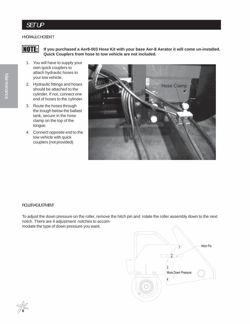
SET UPHYDRAULIC HOSE KIT
If you purchased a Aer8-003 Hose Kit with your base Aer-8 Aerator it will come un-installed.Quick Couplers from hose to tow vehicle are not included.
1. You will have to supply yourown quick couplers toattach hydraulic hoses toyour tow vehicle.
2. Hydraulic fittings and hosesshould be attached to thecylinder. If not, connect oneend of hoses to the cylinder.
3. Route the hoses throughthe trough below the ballasttank, secure in the hoseclamp on the top of thetongue.
4. Connect opposite end to thetow vehicle with quickcouplers (not provided).
ROLLER ADJUSTMENT
To adjust the down pressure on the roller, remove the hitch pin and rotate the roller assembly down to the nextnotch. There are 4 adjustment notches to accom-modate the type of down pressure you want.

7
Main
tena
nce
OPERATION
In excessive stony conditions reduce operating speed.
1. Attach Aer-8 to tow vehicle.
2. Fill ballast tank.
3. Check for any leaks before heading toturf.
4. Lower Aer-8 into the ground so tinepenetrate the soil to desired depth.
5. Drive the tow vehicle at speeds that aresafe.
6. Do Not make sharp turns with the tinesin the ground. Lift Aer-8 out of the groundwhen making sharp turns.
7. Compacted areas may have to beaerated more than once.
8. When Aer-8 is not in use, remove jackpins, extend legs to maximum exten-sion, replace jack pins.
CYLINDER LOCKOUT BARThere is a cylinder lockout attached to the rear pivot arm. This is a security guard used when the cylinder needsto be extended for a long period of time, such as for maintenance. Placed over the cylinder rod when it is fullyextended and pin in place. When not in use return to rear pivot arm for storage.

8
Maintenance
MAINTENANCE
Before servicing or making adjustments to machine, stop engine on tow vehicle and remove keyfrom ignition. Securely prop Aer-8 on jack stands.
Use all procedures and parts prescribed by the manufacturer.
Before operating this machine, become familiar with all controls and functions of this unit and the tow vehicle.Also complete all maintenance requirements and read all safety warnings. By knowing both machines thor-oughly, how it operates and by doing the prescribed maintenance steps, you can expect relatively trouble-freeoperation for years to come.
TOW VEHICLEYou will need a heavy duty vehicle with 4 wheel brakes and 3-point hitch. 3-point is standard on Aer-8 Aerifier.
Transport Frame Assembly requires a clevis hitch and a 3/4 diameter by 4" pin with some type of lock. Towvehicle must be capable of 825 lb tongue weight.
DAILY CHECKLIST1. Check engine oil level in tow vehicle. Add as needed. DO NOT OVERFILL.
2. Check aerifier for loose or missing nuts, bolts, screws, etc., and tighten or replace as needed..
3. Check that all tines are in good condition.
4. Grease bearings daily after each use.
If transport frame assembly in installed:
5. Check hydraulic hoses for any leaks or loose connections.
6. Check tire pressure. 20 psi (1.4 bar)
7. Check electrical system for loose connections or frayed wiring, including battery cables. Replace anyfaulty equipment or tighten if loose.
OPERATION SAFETY1. Before operation check to see that reel is rotating properly.
2. 3-point lift arms of tow vehicle must not be locked, but in floating position.
3. Always lift tines completely out of the soil before making sharp turns.
4. Do not aerate during extended periods of dry periods without irrigation.
5. When not in use, remove the jack pin and extend the legs to maximum extension, reinsert the jack pinand secure with a clip. Always use jack stands for safe storage.
LUBRICATIONUse No. 2 General Purpose Lithium Base Grease and lubricate DAILY. The Aerifier has 2 grease fittings, oneon each pillow block on each side of the reel. When inserting grease, be careful not to ruin the seal, if this hap-pens, replace the seal at once. Be sure to wipe grease fitting clean before injecting grease. Give only one or twopumps of grease at each lubrication.
9
Main
tena
nce
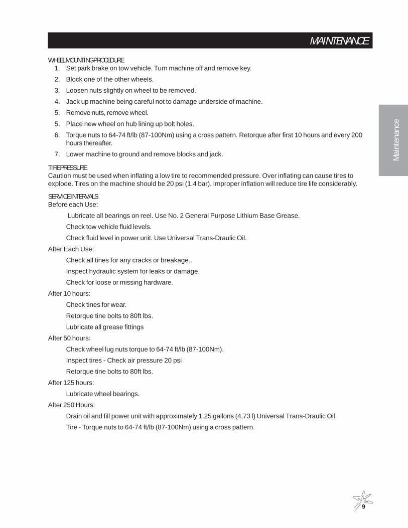
MAINTENANCEWHEEL MOUNTING PROCEDURE
1. Set park brake on tow vehicle. Turn machine off and remove key.
2. Block one of the other wheels.
3. Loosen nuts slightly on wheel to be removed.
4. Jack up machine being careful not to damage underside of machine.
5. Remove nuts, remove wheel.
5. Place new wheel on hub lining up bolt holes.
6. Torque nuts to 64-74 ft/lb (87-100Nm) using a cross pattern. Retorque after first 10 hours and every 200hours thereafter.
7. Lower machine to ground and remove blocks and jack.
TIRE PRESSURECaution must be used when inflating a low tire to recommended pressure. Over inflating can cause tires toexplode. Tires on the machine should be 20 psi (1.4 bar). Improper inflation will reduce tire life considerably.
SERVICE INTERVALSBefore each Use:
Lubricate all bearings on reel. Use No. 2 General Purpose Lithium Base Grease.
Check tow vehicle fluid levels.
Check fluid level in power unit. Use Universal Trans-Draulic Oil.
After Each Use:
Check all tines for any cracks or breakage..
Inspect hydraulic system for leaks or damage.
Check for loose or missing hardware.
After 10 hours:
Check tines for wear.
Retorque tine bolts to 80ft lbs.
Lubricate all grease fittings
After 50 hours:
Check wheel lug nuts torque to 64-74 ft/lb (87-100Nm).
Inspect tires - Check air pressure 20 psi
Retorque tine bolts to 80ft lbs.
After 125 hours:
Lubricate wheel bearings.
After 250 Hours:
Drain oil and fill power unit with approximately 1.25 gallons (4,73 l) Universal Trans-Draulic Oil.
Tire - Torque nuts to 64-74 ft/lb (87-100Nm) using a cross pattern.

10
Maintenance
MAINTENANCEHILLSIDE OPERATIONDo NOT stop or start suddenly on any slope. Be especially cautious when changing direction. Do NOT operate onslopes greater than 20°.
BATTERYBatteries normally produce explosive gases which can cause personal injury. Do not allow flames, sparks or any ig-nited object to come near the battery. When charging or working near battery, always shield your eyes and always pro-vide proper ventilation.
Battery cable should be disconnected before using “Fast Charge”.
Charge battery at 15 amps for 10 minutes or 7 amps for 30 minutes. Do not exceed the recommended charging rate. Ifelectrolyte starts boiling over, decrease charging.
Always remove grounded (-) battery clamp first and replace it last. Avoid hazards by:
1. Filling batteries in well-ventilated areas.
2. Wear eye protection and rubber gloves.
3. Avoid breathing fumes when electrolyte is added.
4. Avoid spilling or dripping electrolyte.
Battery Electrolyte is an acidic solution and should be handled with care. If electrolyte is splashed onany part of your body, flush all contact areas immediately with liberal amounts of water. Get medicalattention immediately.

11
Main
tena
nce
STORAGE1. Before storing clean machine thoroughly.
2. Check bolts and nuts, tighten as necessary.
3. Make all repairs that are needed and remove any debris.
4. Store in a clean and dry area.
5. Make sure reel is on level ground.
6. Lower all 4 jack stands if Transport Assembly is not installed. Secure pins.
7. If transport Assembly is installed lower front jack stands and the trailer hitch on the tongue. Secure pins.
8. If roller is installed, it will act as the rear jacks. Lower roller to the lowest position then lower front jacks.Secure pins.
8. Only after Aer-8 is securely placed on a level surface should you remove from the tow vehicle.

12
Parts
AER8-001 HYDRAULIC TRANSPORT FRAME
AER8-001 HYDRAULIC TRANSPORT FRAMEREF# PART# DESCRIPTION QUANTITY
1 74-257 Hitch Pin 12 78-240 Trailer Jack 13 74-241 Tongue 14 74-156 Decal, reflector 45 HB-34-10-300 Bolt 3/4 -10 x 3 4
HMB-34-10 Machine Bushing 3/4 x 10GA 4HNTL-34-10 Lock Nut 3/4-10 4
6 74-244 Axle 17 60-130 Tire and Wheel 2
60-130-01 Tire, 18 x 9.5 x 8 260-130-02 Wheel 2
8 74-254 Cylinder Stop 1HB-38-16-275 Bolt 3/8 -16 x 2-3/4 1HNW-38-16 Wing nut 3/8-16 1
9 HCP-100-400 Clevis pin 1 x 4 2HP-316-200 Cotter pin 3/16 x 2 2
10 78-225 Hydraulic Cylinder 118-185 3/8 Elbow 2
11 13-652 Hose Clamp (part of tongue) 212 30-071 Hub Assembly 2
Must use AER8-002 Electric/Hydraulic Lift or AER8-003 Hydraulic Hose kit

13
Parts
AER8-003 HYDRAULIC HOSE KIT
AER8-003 HYDRAULIC HOSE KITREF# PART# DESCRIPTION QUANTITY
1 18-185 3/8 Straight Thread Elbow (come with AER8-001) 22 74-246 Hydraulic Hose - 22' 2
Quick Couplers are not included.AER-001 Hydraulic Transport Kit Required.
14
Parts
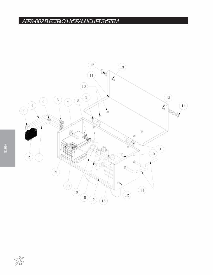
AER8-002 ELECTRIC/HYDRAULIC LIFT SYSTEM

15
Parts
AER8-002 ELECTRIC/HYDRAULIC LIFT SYSTEMREF# PART# DESCRIPTION QUANTITY
1 74-274 15' Parallel Cable System 12 18-446-01 Remote Switch 13 74-271 Multi-Pole Power Connector 14 74-275 8' Parallel Cable System 15 HNW-38-16 Wing Nut 3/8 - 16 1
HW-38 Washer 3/8 1HWL-38 Lock Washer 3/8 1
6 18-445 Cord Connectors 17 74-234 Battery Hold Down 1
15-020 Grip 1HB-38-16-100 Bolt 3/8 - 16 x 1 1
8 22-055 Battery Cable Red 19 74-231 Hinge 2
10 HB-516-18-075 Bolt 5/16 -18 x 3/4 6HNFL-516-18 Flange Lock Nut 5/16 - 18 6
11 74-248 Motor Box Cover 18947-31 Trim Seal 31" 225-277 Decal, Warning 125-373 Decal, 7" Smithco Star 1
12 15-437 Latch 213 HSM-10-32-112 Machine Screw #10-32 x 11/8 6
HNFL-10-32 Flange Lock Nut # 10 - 32 614 74-232 Hose - 72" 215 74-230 Hose - 17" 116 74-229 Hose - 16" 1
8947-74 Trim Seal 74" 117 74-233 Motor Box 118 18-168 3/8 Straight Thread Elbow 219 18-446 Power Unit 120 76-327 Battery Cable - Black 121 Not Included Battery - Automotive type 24F-12 Volt
74-273 60 AMP Fuse

16
Parts

17
Parts
AER 8-004 3-POINT HITCH DRAWING
3-POINT HITCH PARTS LISTREF# PART# DESCRIPTION QUANTITY
1 74-279 3-Point Hitch Frame 12 HB-34-10-300 Bolt 3/4 - 10 x 3 6
HMB-34-10 Machine Bushing 3/4 x 10GA 6HNTL-34-10 Lock Nut 3/4 - 10 6
3 74-282 Mount Brackets 24 HB-38-16-125 Bolt 3/8 - 16 x 11/4 4
HNTL-38-16 Lock Nut 3/8 - 16 4

18
Parts
AER-8 "TURF QUAKE" 5" SPACING DRAWING

19
Parts
AER-8 "TURF QUAKE" 5" SPACING PARTS LISTREF# PART# DESCRIPTION QUANTITY
1 74-228 Kick Stand Mount 42 HCP-12-300 Clevis Pin, 1/2 x 3 4
HHP-177 Bridge Pin, .177 x 33/4 43 74-227 Kickstand Leg 44 16-557 Square Cap 45 74-245 Mainframe, 60" 1
74-280 Mainframe, 78" 174-157 Decal, Aer-8 2
6 HB-12-13-125 Hex Bolt, 1/2 - 13 x 11/4 4HNFL-12-13 Flange Lock Nut, 1/2 - 13 4
7 74-243 Tank Carrier 28 16-150 Double Thread Fitting 19 HB-38-16-275 Hex Bolt, 3/8 - 13 x 22/4 4
HNTL-38-16 Lock Nut, 3/8 - 16 410 74-242 Tank Strap 211 74-211 100 Gal. Tank 1
10-234-01 Cover 112 10-389 Plug, 11/4 113 16-960 Spigot 114 74-290 Manual Canister 115 74-213 Bearing 2
HB-12-13-175 Hex Bolt, 1/2 - 13 x 13/4 4HW-12 Flat Washer, 1/2 4HWL-12 Lock Washer, 1/2 4
16 HB-12-13-125 Hex Bolt, 1/2 - 13 x 11/4 8HNFL-12-13 Flange Lock Nut, 1/2 - 13 8
60" AER817* 74-277 60" Knife Reel, 5" Spacing 118* 74-259 "Turf Quake" Fracture Tine 4819* 74-266 UNF Flange Bolt 96
74-267 UNF Flange Nut 96
* AER8-60R601 60" Turf Quake 5" Reel Assembly
78" AER817** 74-288 78" Knife Reel, 5" Spacing 118** 74-259 "Turf Quake" Fracture Tine 6019** 74-266 UNF Flange Bolt 120
74-267 UNF Flange Nut 120
** AER8-78R781 78" Turf Quake 5" Reel Assembly

20
Parts
AER-8 "TURF QUAKE" 7½" SPACING DRAWING

21
Parts
AER-8 "TURF QUAKE" 7½" SPACING PARTS LISTREF# PART# DESCRIPTION QUANTITY
1 74-228 Kickstand Mount 42 HCP-12-300 Clevis Pin, 1/2 x 3 4
HHP-177 Bridge Pin, .177 x 33/4 43 74-227 Kickstand Leg 44 16-557 Square Cap 45 74-245 Mainframe, 60" 1
74-280 Mainframe, 78" 174-157 Decal, Aer-8 2
6 HB-12-13-125 Hex Bolt, 1/2 - 13 x 11/4 4HNFL-12-13 Flange Lock Nut, 1/2 - 13 4
7 74-243 Tank Carrier 28 16-150 Double Thread Fitting 19 HB-38-16-275 Hex Bolt, 3/8 - 13 x 22/4 4
HNTL-38-16 Lock Nut, 3/8 - 16 410 74-242 Tank Strap 211 74-211 100 Gal. Tank 1
10-234-01 Cover 112 10-389 Plug, 11/4 113 16-960 Spigot 114 74-290 Manual Canister 115 74-213 Bearing 2
HB-12-13-175 Hex Bolt, 1/2 - 13 x 13/4 4HW-12 Flat Washer, 1/2 4HWL-12 Lock Washer, 1/2 4
16 HB-12-13-125 Hex Bolt, 1/2 - 13 x 11/4 8HNFL-12-13 Flange Lock Nut, 1/2 - 13 8
60" AER817* 74-263 60" Knife Reel, 7½" Spacing 118* 74-259 "Turf Quake" Fracture Tine 3219* 74-266 UNF Flange Bolt 64
74-267 UNF Flange Nut 64
* AER8-60R602 60" Turf Quake 7.5" Reel Assembly78" AER8
17** 74-289 78" Knife Reel, 7½" Spacing 118** 74-259 "Turf Quake" Fracture Tine 4019** 74-266 UNF Flange Bolt 80
74-267 UNF Flange Nut 80
** AER8-78R782 78" Turf Quake 7.5" Reel Assembly
22
Parts
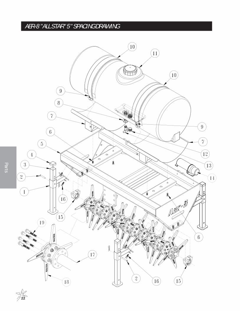
AER-8 "ALL STAR" 5" SPACING DRAWING

23
Parts
AER-8 "ALL STAR" 5" SPACING PARTS LISTREF# PART# DESCRIPTION QUANTITY
1 74-228 Kickstand Mount 42 HCP-12-300 Clevis Pin, 1/2 x 3 4
HHP-177 Bridge Pin, .177 x 33/4 43 74-227 Kickstand Leg 44 16-557 Square Cap 45 74-245 Mainframe, 60" 1
74-280 Mainframe, 78" 174-157 Decal, Aer-8 2
6 HB-12-13-125 Hex Bolt, 1/2 - 13 x 11/4 4HNFL-12-13 Flange Lock Nut, 1/2 - 13 4
7 74-243 Tank Carrier 28 16-150 Double Thread Fitting 19 HB-38-16-275 Hex Bolt, 3/8 - 13 x 22/4 4
HNTL-38-16 Lock Nut, 3/8 - 16 410 74-242 Tank Strap 211 74-211 100 Gal. Tank 1
10-234-01 Cover 112 10-389 Plug, 11/4 113 16-960 Spigot 114 74-290 Manual Canister 115 74-213 Bearing 2
HB-12-13-175 Hex Bolt, 1/2 - 13 x 13/4 4HW-12 Flat Washer, 1/2 4HWL-12 Lock Washer, 1/2 4
16 HB-12-13-125 Hex Bolt, 1/2 - 13 x 11/4 8HNFL-12-13 Flange Lock Nut, 1/2 - 13 8
60" AER817* 74-277 60" Knife Reel, 5" Spacing 118* 74-258 "All Star" Sport Tine 4819* 74-266 UNF Flange Bolt 96
74-267 UNF Flange Nut 96
* AER8-60R603 60" All Star 5" Reel Assembly
78" AER817** 74-288 78" Knife Reel, 5" Spacing 118** 74-258 "All Star" Sport Tine 6019** 74-266 UNF Flange Bolt 120
74-267 UNF Flange Nut 120
** AER8-78R783 78" All Star 5" Reel Assembly
24
Parts
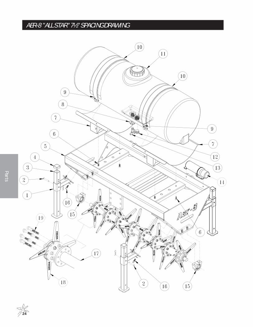
AER-8 "ALL STAR" 7½" SPACING DRAWING
25
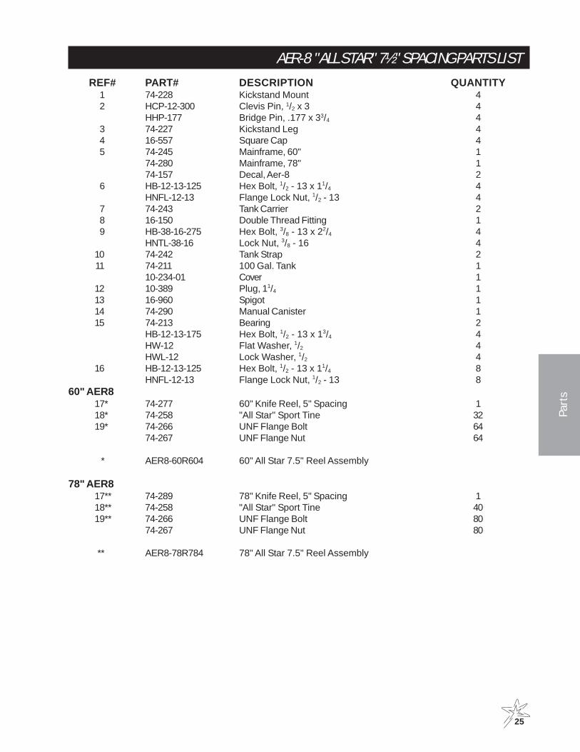
Parts
AER-8 "ALL STAR" 7½" SPACING PARTS LISTREF# PART# DESCRIPTION QUANTITY
1 74-228 Kickstand Mount 42 HCP-12-300 Clevis Pin, 1/2 x 3 4
HHP-177 Bridge Pin, .177 x 33/4 43 74-227 Kickstand Leg 44 16-557 Square Cap 45 74-245 Mainframe, 60" 1
74-280 Mainframe, 78" 174-157 Decal, Aer-8 2
6 HB-12-13-125 Hex Bolt, 1/2 - 13 x 11/4 4HNFL-12-13 Flange Lock Nut, 1/2 - 13 4
7 74-243 Tank Carrier 28 16-150 Double Thread Fitting 19 HB-38-16-275 Hex Bolt, 3/8 - 13 x 22/4 4
HNTL-38-16 Lock Nut, 3/8 - 16 410 74-242 Tank Strap 211 74-211 100 Gal. Tank 1
10-234-01 Cover 112 10-389 Plug, 11/4 113 16-960 Spigot 114 74-290 Manual Canister 115 74-213 Bearing 2
HB-12-13-175 Hex Bolt, 1/2 - 13 x 13/4 4HW-12 Flat Washer, 1/2 4HWL-12 Lock Washer, 1/2 4
16 HB-12-13-125 Hex Bolt, 1/2 - 13 x 11/4 8HNFL-12-13 Flange Lock Nut, 1/2 - 13 8
60" AER817* 74-277 60" Knife Reel, 5" Spacing 118* 74-258 "All Star" Sport Tine 3219* 74-266 UNF Flange Bolt 64
74-267 UNF Flange Nut 64
* AER8-60R604 60" All Star 7.5" Reel Assembly
78" AER817** 74-289 78" Knife Reel, 5" Spacing 118** 74-258 "All Star" Sport Tine 4019** 74-266 UNF Flange Bolt 80
74-267 UNF Flange Nut 80
** AER8-78R784 78" All Star 7.5" Reel Assembly

26
Parts
AER-8 "AERFINE" 3" SPACING DRAWING
27
Parts
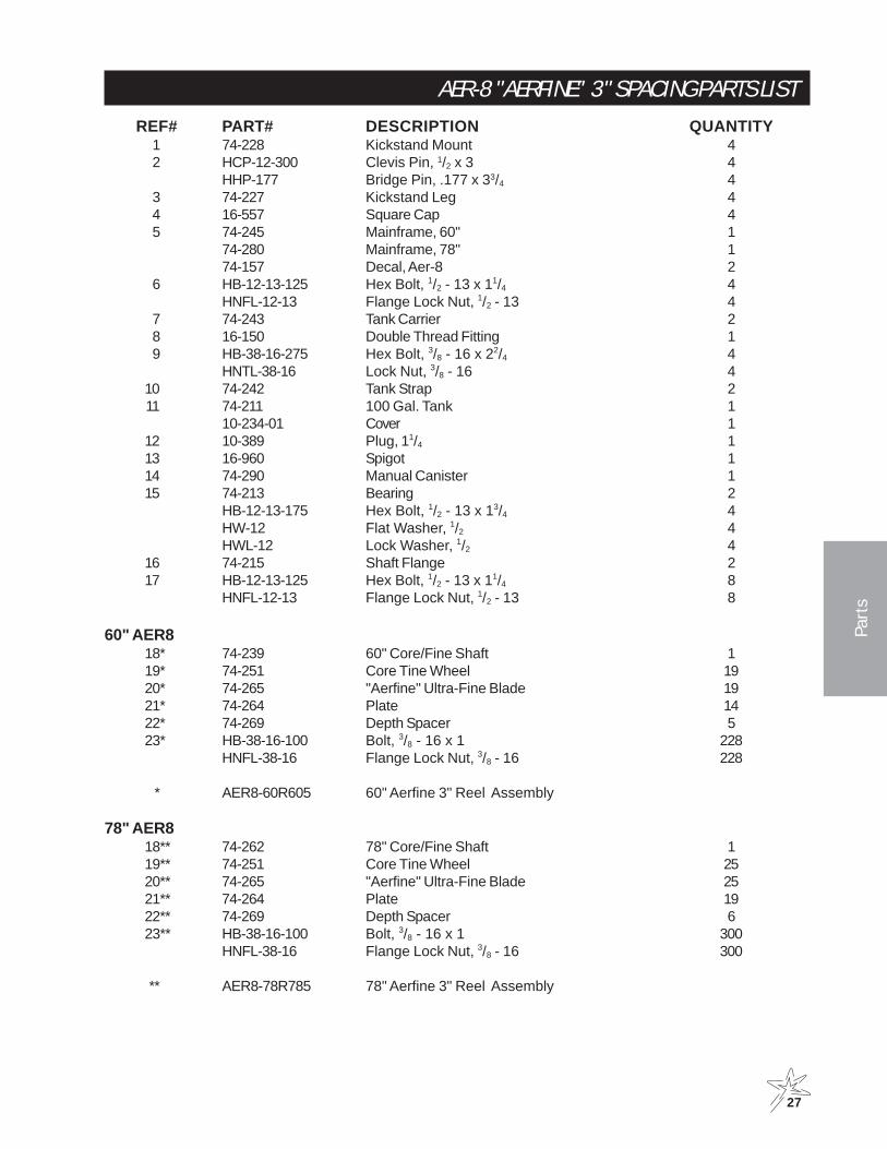
AER-8 "AERFINE" 3" SPACING PARTS LISTREF# PART# DESCRIPTION QUANTITY
1 74-228 Kickstand Mount 42 HCP-12-300 Clevis Pin, 1/2 x 3 4
HHP-177 Bridge Pin, .177 x 33/4 43 74-227 Kickstand Leg 44 16-557 Square Cap 45 74-245 Mainframe, 60" 1
74-280 Mainframe, 78" 174-157 Decal, Aer-8 2
6 HB-12-13-125 Hex Bolt, 1/2 - 13 x 11/4 4HNFL-12-13 Flange Lock Nut, 1/2 - 13 4
7 74-243 Tank Carrier 28 16-150 Double Thread Fitting 19 HB-38-16-275 Hex Bolt, 3/8 - 16 x 22/4 4
HNTL-38-16 Lock Nut, 3/8 - 16 410 74-242 Tank Strap 211 74-211 100 Gal. Tank 1
10-234-01 Cover 112 10-389 Plug, 11/4 113 16-960 Spigot 114 74-290 Manual Canister 115 74-213 Bearing 2
HB-12-13-175 Hex Bolt, 1/2 - 13 x 13/4 4HW-12 Flat Washer, 1/2 4HWL-12 Lock Washer, 1/2 4
16 74-215 Shaft Flange 217 HB-12-13-125 Hex Bolt, 1/2 - 13 x 11/4 8
HNFL-12-13 Flange Lock Nut, 1/2 - 13 8
60" AER818* 74-239 60" Core/Fine Shaft 119* 74-251 Core Tine Wheel 1920* 74-265 "Aerfine" Ultra-Fine Blade 1921* 74-264 Plate 1422* 74-269 Depth Spacer 523* HB-38-16-100 Bolt, 3/8 - 16 x 1 228
HNFL-38-16 Flange Lock Nut, 3/8 - 16 228
* AER8-60R605 60" Aerfine 3" Reel Assembly
78" AER818** 74-262 78" Core/Fine Shaft 119** 74-251 Core Tine Wheel 2520** 74-265 "Aerfine" Ultra-Fine Blade 2521** 74-264 Plate 1922** 74-269 Depth Spacer 623** HB-38-16-100 Bolt, 3/8 - 16 x 1 300
HNFL-38-16 Flange Lock Nut, 3/8 - 16 300
** AER8-78R785 78" Aerfine 3" Reel Assembly

28
Parts
AER-8 "AERFINE" 5" SPACING DRAWING

29
Parts
AER-8 "AERFINE" 5" SPACING PARTS LISTREF# PART# DESCRIPTION QUANTITY
1 74-228 Kickstand Mount 42 HCP-12-300 Clevis Pin, 1/2 x 3 4
HHP-177 Bridge Pin, .177 x 33/4 43 74-227 Kickstand Leg 44 16-557 Square Cap 45 74-245 Mainframe, 60" 1
74-280 Mainframe, 78" 174-157 Decal, Aer-8 2
6 HB-12-13-125 Hex Bolt, 1/2 - 13 x 11/4 4HNFL-12-13 Flange Lock Nut, 1/2 - 13 4
7 74-243 Tank Carrier 28 16-150 Double Thread Fitting 19 HB-38-16-275 Hex Bolt, 3/8 - 16 x 22/4 4
HNTL-38-16 Lock Nut, 3/8 - 16 410 74-242 Tank Strap 211 74-211 100 Gal. Tank 1
10-234-01 Cover 112 10-389 Plug, 11/4 113 16-960 Spigot 114 74-290 Manual Canister 115 74-213 Bearing 2
HB-12-13-175 Hex Bolt, 1/2 - 13 x 13/4 4HW-12 Flat Washer, 1/2 4HWL-12 Lock Washer, 1/2 4
18 HB-12-13-125 Hex Bolt, 1/2 - 13 x 11/4 8HNFL-12-13 Flange Lock Nut, 1/2 - 13 8
60" AER816 74-215 Shaft Flange 217 74-281 11/2 " Spacer 219* 74-239 60" Core/Fine Shaft 120* 74-251 Core Tine Wheel 1021* 74-265 "Aerfine" Ultra-Fine Blade 1022* 74-264 Plate 523* 74-240 Spacer Tube 924* 74-269 Depth Spacer 525* HB-38-16-100 Bolt, 3/8 - 16 x 1 120
HNFL-38-16 Flange Lock Nut, 3/8 - 16 120
* AER8-60R606 60" Aerfine 5" Reel Assembly
78" AER816 74-215 Shaft Flange 217 74-283 1/2 " Spacer 219** 74-262 78" Core/Fine Shaft 120** 74-251 Core Tine Wheel 1521** 74-265 "Aerfine" Ultra-Fine Blade 1522** 74-264 Plate 923** 74-240 Spacer Tube 1424** 74-269 Depth Spacer 625** HB-38-16-100 Bolt, 3/8 - 16 x 1 270
HNFL-38-16 Flange Lock Nut, 3/8 - 16 270
** AER8-78R786 78" Aerfine 5" Reel Assembly
30
Parts
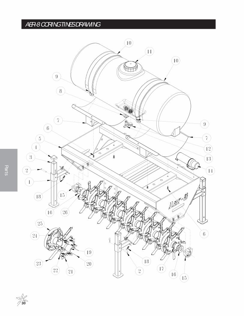
AER-8 CORING TINES DRAWING

31
Parts
AER-8 CORING TINES PARTS LISTREF# PART# DESCRIPTION QUANTITY
1 74-228 Kickstand Mount 42 HCP-12-300 Clevis Pin, 1/2 x 3 4
HHP-177 Bridge Pin, .177 x 33/4 43 74-227 Kickstand Leg 44 16-557 Square Cap 45 74-245 Mainframe, 60" 1
74-280 Mainframe, 78" 174-157 Decal, Aer-8 2
6 HB-12-13-125 Hex Bolt, 1/2 - 13 x 11/4 4HNFL-12-13 Flange Lock Nut, 1/2 - 13 4
7 74-243 Tank Carrier 28 16-150 Double Thread Fitting 19 HB-38-16-275 Hex Bolt, 3/8 - 16 x 22/4 4
HNTL-38-16 Lock Nut, 3/8 - 16 410 74-242 Tank Strap 211 74-211 100 Gal. Tank 1
10-234-01 Cover 112 10-389 Plug, 11/4 113 16-960 Spigot 114 74-290 Manual Canister 115 74-213 Bearing 2
HB-12-13-175 Hex Bolt, 1/2 - 13 x 13/4 4HW-12 Flat Washer, 1/2 4HWL-12 Lock Washer, 1/2 4
16 74-215 Shaft Flange 218 HB-12-13-125 Hex Bolt, 1/2 - 13 x 11/4 8
HNFL-12-13 Flange Lock Nut, 1/2 - 13 8
60" AER817 74-281 11/2 " Spacer 219* 74-240 Spacer Tube 920* 74-239 60" Core/Fine Shaft 121* HB-38-16-175 Bolt, 3/8 - 16 x 1 3/4 180
HNFL-38-16 Flange Lock Nut, 3/8 - 16 18022* 74-264 Plate 1023* 74-225 Coring Tine 6024* 74-251 Core Tine Wheel 1025* 74-269 Depth Spacer 5
* AER8-60R607 60" Coring Tine Reel Assembly
78" AER817 74-283 1/2 " Spacer 219** 74-240 Spacer Tube 1420** 74-262 78" Core/Fine Shaft 121** HB-38-16-175 Bolt, 3/8 - 16 x 1 3/4 270
HNFL-38-16 Flange Lock Nut, 3/8 - 16 27022** 74-264 Plate 923** 74-225 Coring Tine 9024** 74-251 Core Tine Wheel 1525** 74-269 Depth Spacer 6
** AER8-78R787 78" Coring Tine Reel Assembly

32
Parts
REAR ROLLER DRAWING

33
Parts
REAR ROLLER PARTS LISTREF# PART# DESCRIPTION QUANTITY
1 74-245 Mainframe, 60" 174-280 Mainframe, 78" 1
2 74-247 Adjustment Bracket 2HB-12-13-125 Hex Bolt, 1/2 - 13 x 11/4 8HNFL-12-13 Flange Lock Nut, 1/2 - 13 8
3 7-029 Hitch Pin 2HHP-.177 Cotter Pin 2
4 74-249 RH Roller Bracket 1HG-14-28-180 Grease Fitting 1
5 HB-12-13-175 Bolt, 1/2- 13 x 13/4 46 HB-12-13-125 Bolt, 1/2 -13 x 11/4 2
HW-58 Washer, 5/8 27 74-213 Bearing 2
13 HB-38-16-125 Bolt, 3/8 - 16 x 11/4 4HNTL-38-16 Lock Nut, 3/8 - 16 4
14 74-250 LH Roller Bracket 1HG-14-28-180 Grease Fitting 1
15 74-278 Spacer 274-268 Clevis Pin 2HHP-.177 Cotter Pin 2
60" AER8-6108 74-261 60" Scraper Bar 19 74-260 60" Roller 1
10 74-256 60" Scraper 111 74-255 60" Scraper Strap 112 HBC-516-18-100 Carriage Bolt, 5/16 -18 x 1 8
HNL-516-18 Lock Nut, 5/16 - 18 8
78" AER8-7108 74-286 78" Scraper Bar 19 74-287 78" Roller 1
10 74-285 78" Scraper 111 74-284 78" Scraper Strap 112 HBC-516-18-100 Carriage Bolt, 5/16 -18 x 1 10
HNTL-516-18 Lock Nut, 5/16 - 18 10

34
Refe
renc
e
Reference
DECAL LIST74-156 Decal, Reflector 4 corners of main frame
74-157 Decal, Aer-8 Main Frame Sides
74-210 Decal Hang Tag Aer 8-002
76-305 Decal, Rotating Parts Reel Housing
74-158 Decal, Counter Weight
QUICK REFERENCEREPLACEMENT TANK FITTINGS
BATTERY (NOT SUPPLIED) AUTOMOTIVE TYPE 24F-12 VOLT
HYDRAULIC FLUID HYDRAULIC FLUID 1.25 GAL (4.3 LITER)

The Smithco Commercial Products Two-Year Limited Warranty
Smithco, Inc. (Smithco) warrants your 2007 or newer Smithco Commercial Product (“Product”) purchasedafter January 1, 2007, to be free from defects in materials or workmanship for the period of time listed below.Where a warrantable condition exists, Smithco will repair the Product at no cost to you including diagnosis,labor (at the Smithco standard labor rate, subject to the Smithco flat rate schedule), and parts.
Warranty Duration is:
(1) Two years, 1500 operational hours* from the date of delivery to the original purchaser or three yearsfrom the date of original manufacturer of the product, whichever occurs first. (*Products equippedwith hour meter).
(2) Products used in rental situations are covered for 90 days from date of delivery to original user/renter.
Owner Responsibilities:
As the Product owner, you are responsible for required maintenance and adjustments stated in your Owner’s Manual.Failure to perform required maintenance and adjustments can be grounds for disallowing a warranty claim. You areparticularly responsible to train all present and future operators of this product on the safe operation of thisproduct at your location.
Instructions for Obtaining Warranty Service:
You are responsible for notifying the Authorized Smithco Products Distributor from whom you purchased the Productas soon as you believe a warrantable condition exists and not later than 30 days from discovery of the condition.
If you need help locating an Authorized Smithco Distributor, or if you have questions regarding your warranty rights orresponsibilities, you may contact us at:
Smithco Product Support Department200 W Poplar PO Box 487Cameron, Wisconsin 54822
Telephone: 1-800-891-9435 E-Mail: [email protected]
Maintenance Parts:
Parts scheduled for replacement as required maintenance (“Maintenance Parts”), are warranted for the period of timeup to the scheduled replacement time for that part.
Items/Conditions Not Covered:
Not all product failures or malfunctions that occur during the warranty period are defects in materials orworkman-ship. The items/conditions listed below are not covered by this warranty:
Product failures which result from the use of non-Smithco replacement parts, or from installation and use ofadd-on, modified, or unapproved accessories are not cov-ered.
Product failures which result from failure to perform required maintenance and/or adjustments are not cov-ered.
Product failures that result from operating the Product in an abusive, negligent or reckless manner are notcovered.
This warranty does not apply to parts subject to con-sumption through use, unless found to be defective.Examples of parts which are consumed, or used up, during normal Product operation include, but are notlimited to: blades, tines, teeth, scarifiers, rakes, plates, wear plates, castor wheels, tires, batteries, filters, belts,nozzles, etc.
This warranty does not apply to failures caused by out-side influence. Items considered to be outside influ-ence include, but are not limited to, weather, storage practices, contamination, use of unapproved coolants,lubricants, additives, or chemicals, etc.
This warranty does not apply to normal “wear and tear” items. Normal “Wear and Tear” includes, but is not lim-ited to, damage to seats due to wear or abrasion, worn painted surfaces, scratched decals or windows, etc.
Smithco may require the return of failed parts or components in order to determine the validity of any warrantyclaim.
Smithco will not be obligated to replace components of other manufacturers if inspection by the originalcomponent manufacturer indicates that failure was due to normal wear and tear, expected consumptionthrough use or improper care or service.
Other Legal Disclaimers:
The above remedy for product defects through repair or replacement by an authorized Smithco distributor or dealer isthe purchaser’s sole remedy for any defect. This warranty gives you specific legal rights, and you may also have otherrights which vary from state to state.
THERE ARE NO OTHER EXPRESS WARRANTIES OTHER THAN THOSE SET FORTH ABOVE. ALL IMPLIEDWARRANTIES OF MERCHANTABILITY AND FITNESS FOR USE ARE LIMITED TO THE DURATION OF THELIMITED WARRANTIES CONTAINED HEREIN.
Some states may not allow limitations on how long an implied warranty lasts, so the above limitation may notapply to you.
THE SMITHCO COMPANY IS NOT LIABLE FOR INDIRECT, INCIDENTAL OR CONSEQUENTIAL DAMAGES INCONNECTION WITH THE USE OF THE PRODUCT, INCLUDING ANY COST OR EXPENSE OF PROVIDING ASUBSTITUTE PRODUCT OR SERVICE DURING PERIODS OF MALFUNCTION OR NON-USE.
Some states may not allow the exclusion of indirect, incidental or consequential damages, so the above exclusionmay not apply to you.
Smithco neither assumes, nor authorizes any person to assume for it, any other liability in connection withthe sale or use of this product.
SMITHCO, INC.
Wayne, PA 19087