6 september 2012, hamburg integrated propulsion … · for a container vessel, the corresponding...
TRANSCRIPT
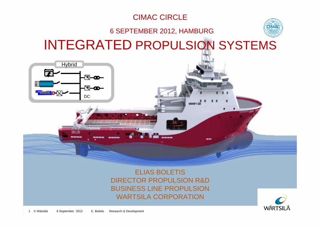
CIMAC CIRCLE
6 SEPTEMBER 2012, HAMBURG
INTEGRATED PROPULSION SYSTEMS
ELIAS BOLETISDIRECTOR PROPULSION R&DBUSINESS LINE PROPULSION
WARTSILA CORPORATION
6 September 2012 E. Boletis Research & Development 1 © Wärtsilä
+-Hybrid
==
+ -Hybrid
==
DC
CIMAC Circle 2012
6 September 2012 E. Boletis Research & Development 2 © Wärtsilä
YOU And The Panel:
1. Elias Boletis, Wärtsilä Propulsion Netherlands B.V., Netherlands (chair)
2. Christof Fenske, MTU Friedrichshafen GmbH, Germany
3. Christian Poensgen, MAN Diesel & Turbo SE, Germany
4. Christian Roduner, ABB Turbo Systems Ltd., Switzerland
5. Feng Wang, Shanghai Marine Diesel Engines Research Institute, China
Purpose of the CIMAC Circle 2012
6 September 2012 E. Boletis Research & Development 3 © Wärtsilä
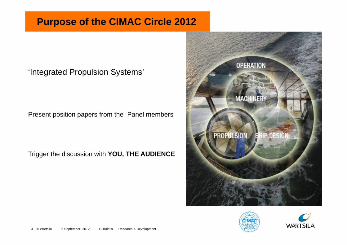
‘Integrated Propulsion Systems’
Present position papers from the Panel members
Trigger the discussion with YOU, THE AUDIENCE
Purpose of the CIMAC Circle 2012
6 September 2012 E. Boletis / Research & Development4 © Wärtsilä
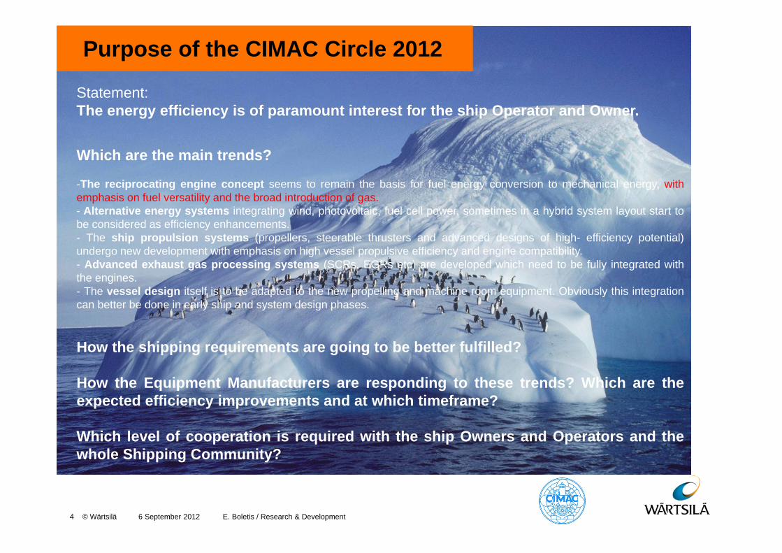
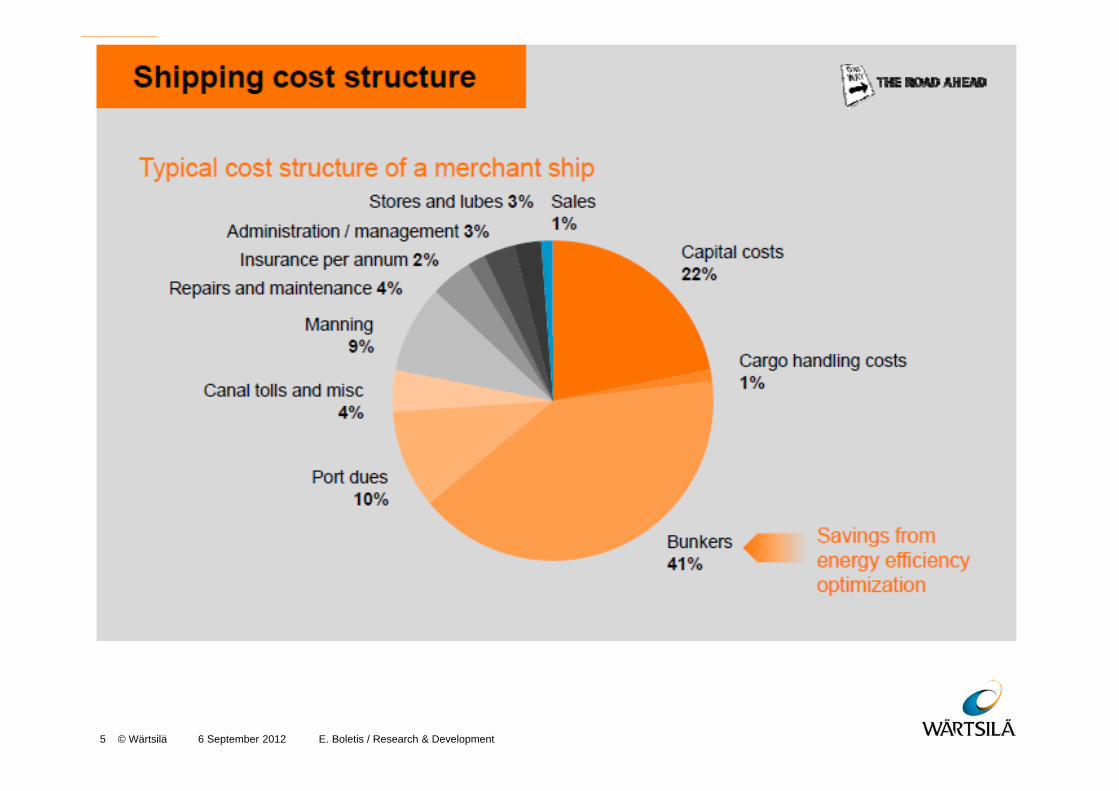
Statement:The energy efficiency is of paramount interest for the ship Operator and Owner.
Which are the main trends?
-The reciprocating engine concept seems to remain the basis for fuel energy conversion to mechanical energy, withemphasis on fuel versatility and the broad introduction of gas.- Alternative energy systems integrating wind, photovoltaic, fuel cell power, sometimes in a hybrid system layout start tobe considered as efficiency enhancements.- The ship propulsion systems (propellers, steerable thrusters and advanced designs of high- efficiency potential)undergo new development with emphasis on high vessel propulsive efficiency and engine compatibility.- Advanced exhaust gas processing systems (SCRs, EGRs etc) are developed which need to be fully integrated withthe engines.- The vessel design itself is to be adapted to the new propelling and machine room equipment. Obviously this integrationcan better be done in early ship and system design phases.
How the shipping requirements are going to be better fulfilled?
How the Equipment Manufacturers are responding to these trends? Which are theexpected efficiency improvements and at which timeframe?
Which level of cooperation is required with the ship Owners and Operators and thewhole Shipping Community?
6 September 2012 E. Boletis / Research & Development 5 © Wärtsilä
6 September 2012 E. Boletis / Research & Development 6 © Wärtsilä

6 September 2012 E. Boletis / Research & Development presentation7 © Wärtsilä
6 September 2012 E. Boletis / Research & Development presentation8 © Wärtsilä
© Wärtsilä

Integrated systems for customized solutions
9 © Wärtsilä
Our aim is to show from a neutral viewpoint a vast range of potential areas for efficiency improvement. They are based on today’s technology and are presented irrespective of the present availability of such solutions either from Wärtsilä or any other supplier.
6 September 2012 E. Boletis Research & Development
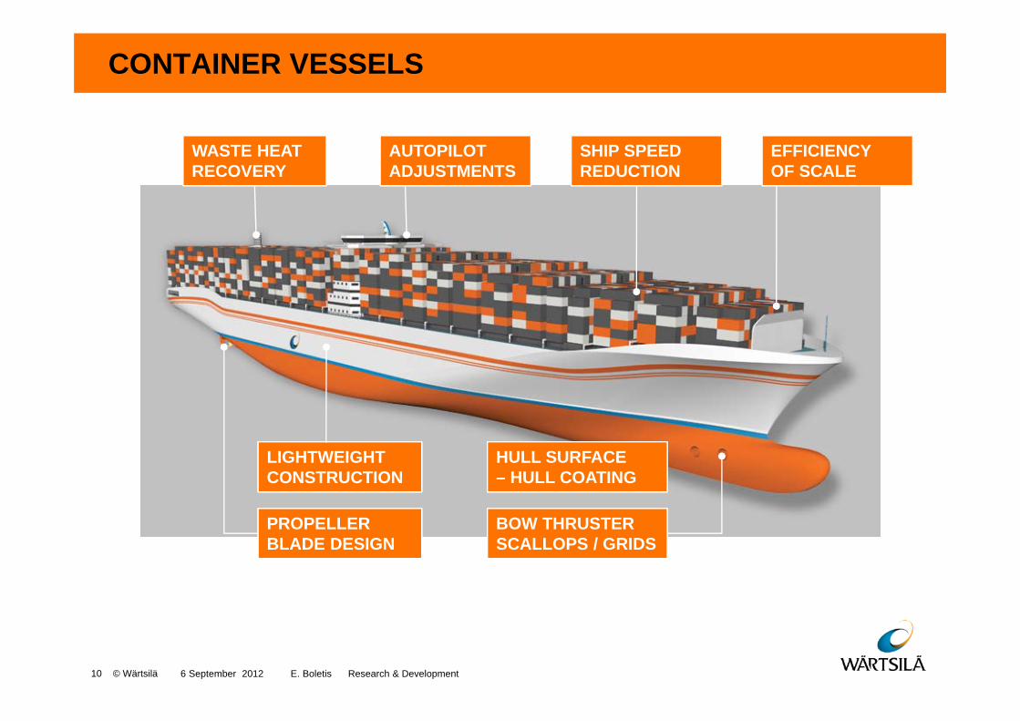
CONTAINER VESSELS
LIGHTWEIGHT CONSTRUCTION
PROPELLER BLADE DESIGN
HULL SURFACE – HULL COATING
BOW THRUSTER SCALLOPS / GRIDS
WASTE HEAT RECOVERY
AUTOPILOT ADJUSTMENTS
SHIP SPEED REDUCTION
EFFICIENCY OF SCALE
6 September 2012 E. Boletis Research & Development 10 © Wärtsilä
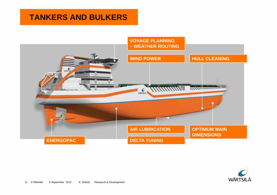
TANKERS AND BULKERS
AIR LUBRICATION
DELTA TUNING
OPTIMUM MAIN DIMENSIONS
ENERGOPAC
HULL CLEANINGWIND POWER
VOYAGE PLANNING– WEATHER ROUTING
6 September 2012 E. Boletis Research & Development 11 © Wärtsilä
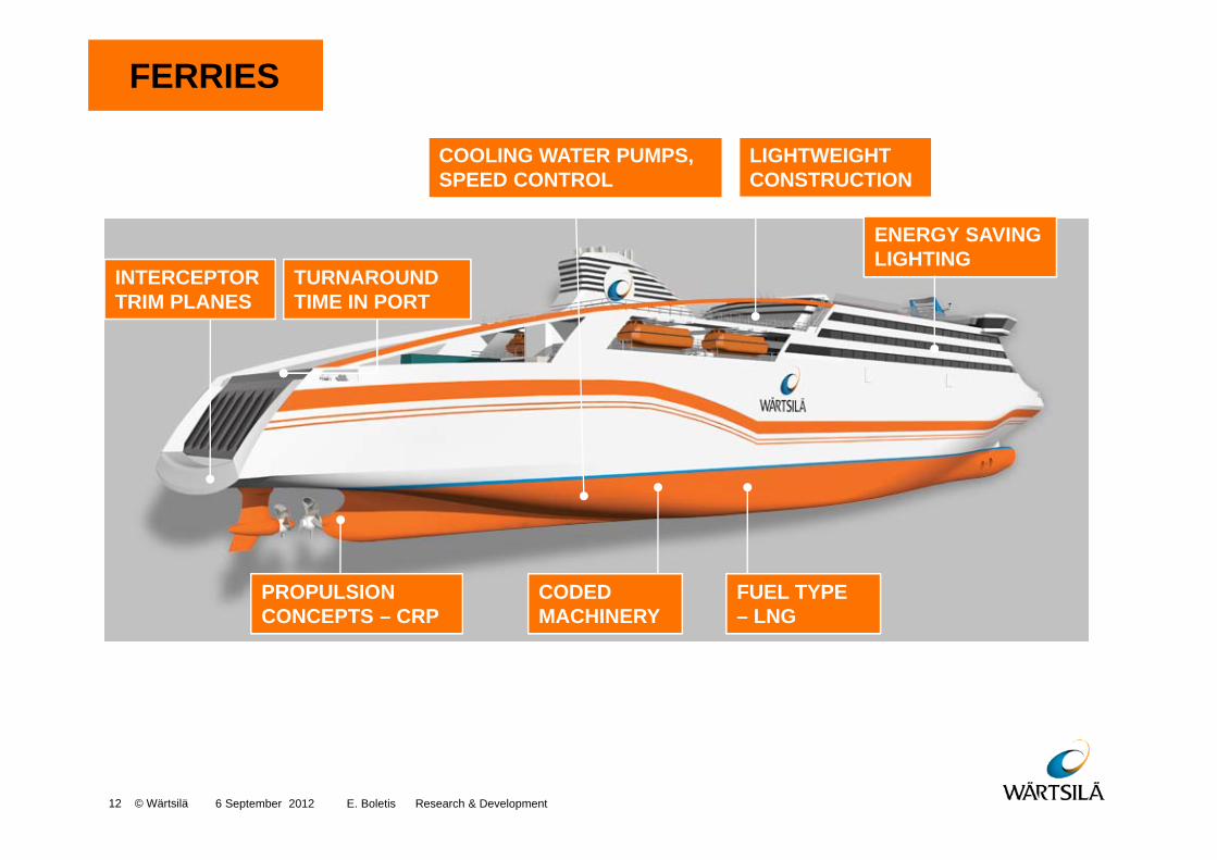
FERRIES
ENERGY SAVING LIGHTING
LIGHTWEIGHT CONSTRUCTION
PROPULSION CONCEPTS – CRP
CODED MACHINERY
FUEL TYPE– LNG
TURNAROUND TIME IN PORT
INTERCEPTOR TRIM PLANES
COOLING WATER PUMPS, SPEED CONTROL
6 September 2012 E. Boletis Research & Development 12 © Wärtsilä
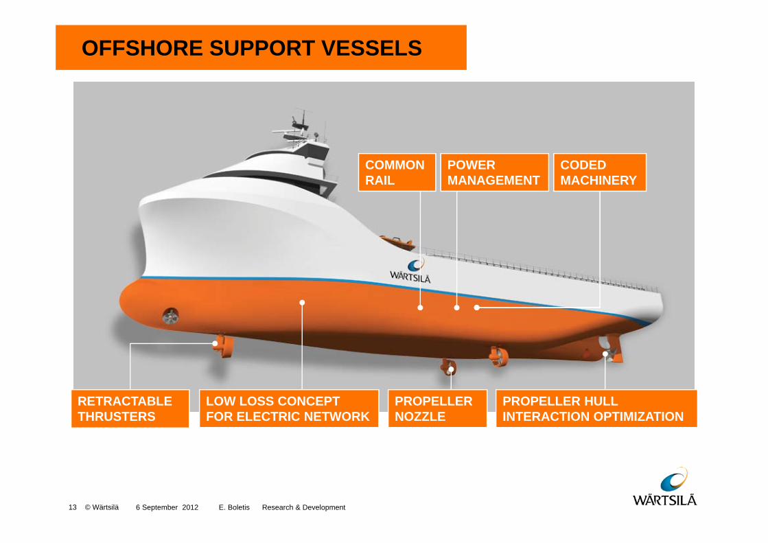
OFFSHORE SUPPORT VESSELS
LOW LOSS CONCEPT FOR ELECTRIC NETWORK
PROPELLER NOZZLE
PROPELLER HULL INTERACTION OPTIMIZATION
RETRACTABLE THRUSTERS
COMMON RAIL
POWER MANAGEMENT
CODED MACHINERY
6 September 2012 E. Boletis Research & Development 13 © Wärtsilä
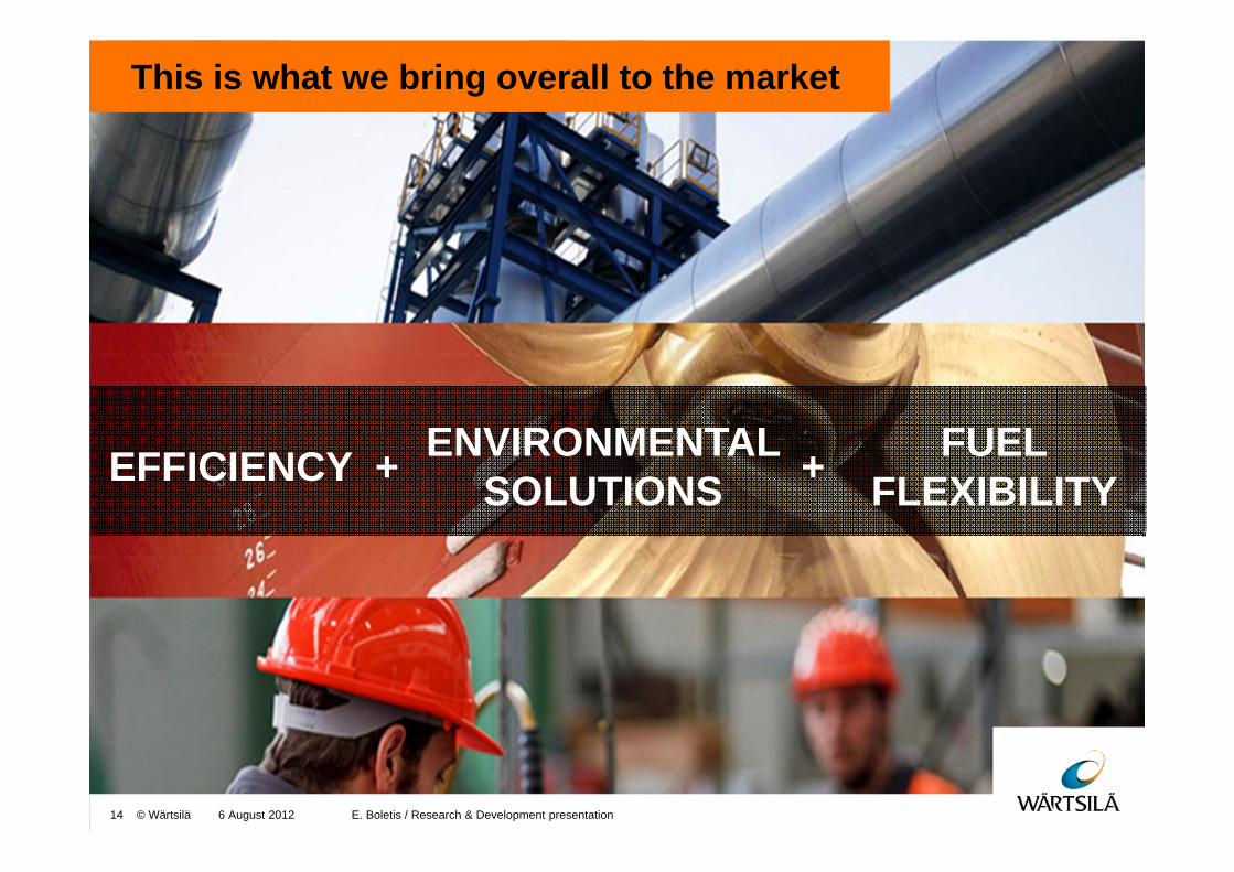
This is what we bring overall to the market
EFFICIENCY + ENVIRONMENTAL SOLUTIONS
FUEL FLEXIBILITY
6 August 2012 E. Boletis / Research & Development presentation14 © Wärtsilä
+

6 September 2012 Shipping in the gas Age15 © Wärtsilä
We have already entered in the gas age
CO2
NOx
SOx
Particulates
Dual-Fuel enginein gas mode
Dieselengine
0
10
20
30
40
50
60
70
80
90
100
Emissionvalues [%]
-20%
-80%
-100%
-100%

16 © Wärtsilä
Gas fuel system - basic description
C. Dual-Fuel Main engine
A. Storage tanks
B. Evaporators
No moving partsin the fuel system!
C B
A
D. Dual-Fuel Aux engines
D
6 September 2012 E. Boletis Research & Development
6 September 2012 Shipping in the gas Age17 © Wärtsilä
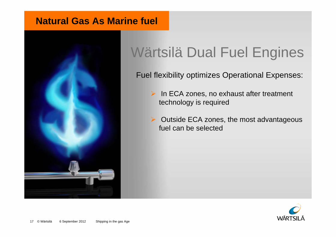
Natural Gas As Marine fuel
Wärtsilä Dual Fuel EnginesFuel flexibility optimizes Operational Expenses:
In ECA zones, no exhaust after treatment technology is required
Outside ECA zones, the most advantageous fuel can be selected

10 Shipping in the gas Age18 © Wärtsilä
Total Concept Optimization
We engineer integrated fuel solutions for LNG delivery, storage, transportation and utilization onboard.
This is what we bring overall to the market
Example of DetailedProducts & Proposals
6 August 2012 E. Boletis / Research & Development presentation19 © Wärtsilä
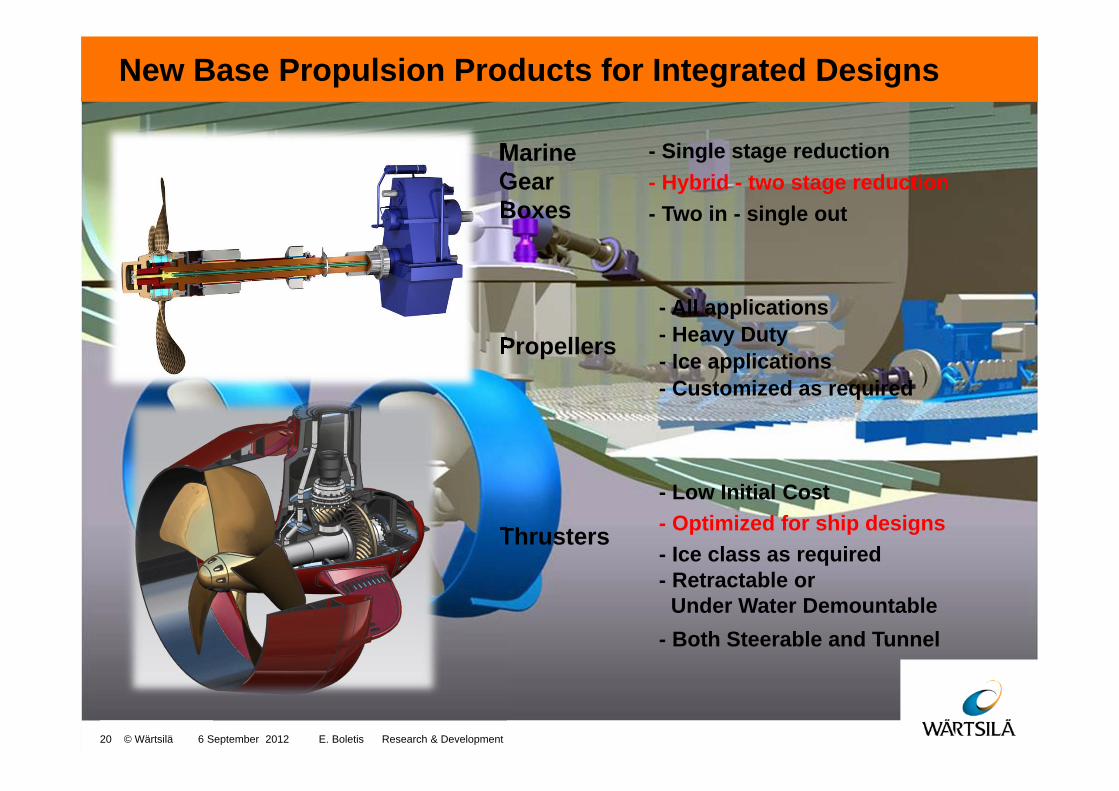
New Base Propulsion Products for Integrated Designs
- Single stage reduction
- Low Initial Cost
MarineGear Boxes
Propellers
Thrusters
- Both Steerable and Tunnel
- Two in - single out
- All applications- Heavy Duty- Ice applications- Customized as required
- Optimized for ship designs - Ice class as required
- Hybrid - two stage reduction
20 © Wärtsilä 6 September 2012 E. Boletis Research & Development
- Retractable or Under Water Demountable
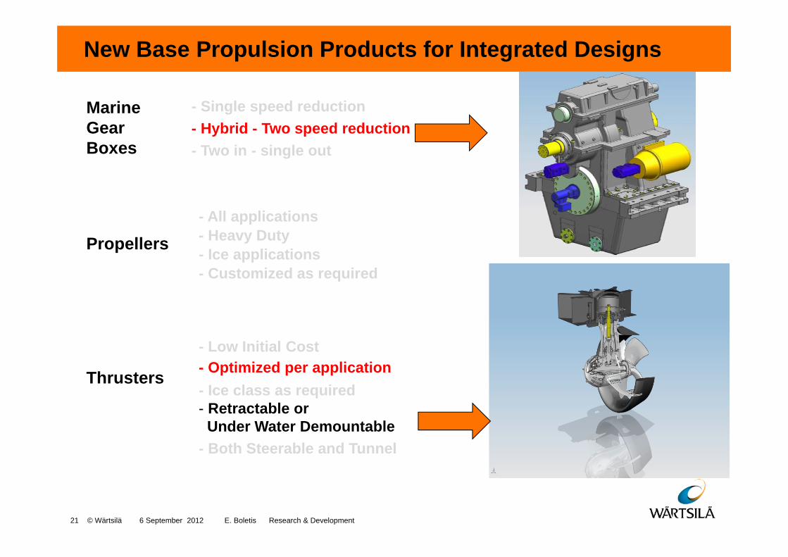
New Base Propulsion Products for Integrated Designs
- Single speed reduction
- Low Initial Cost
MarineGear Boxes
Propellers
Thrusters
- Both Steerable and Tunnel
- Two in - single out
- All applications- Heavy Duty- Ice applications- Customized as required
- Optimized per application - Ice class as required
- Hybrid - Two speed reduction
21 © Wärtsilä 6 September 2012 E. Boletis Research & Development
- Retractable or Under Water Demountable
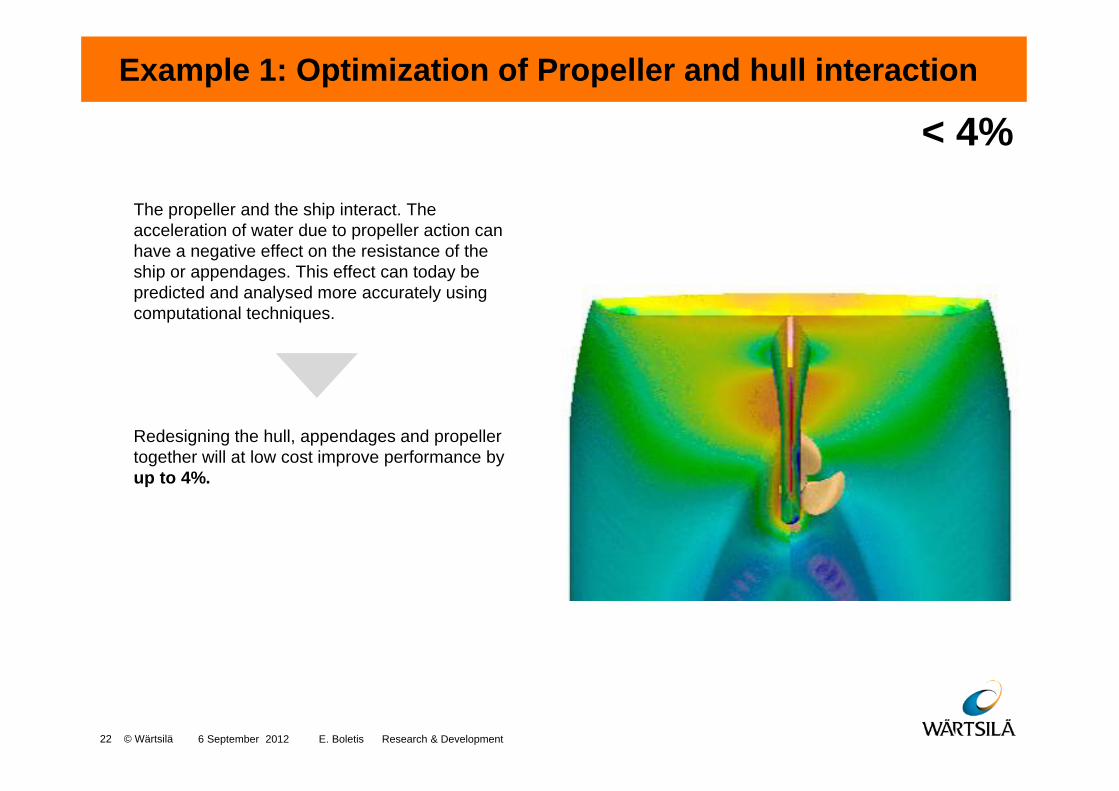
Example 1: Optimization of Propeller and hull interaction
< 4%The propeller and the ship interact. The acceleration of water due to propeller action can have a negative effect on the resistance of the ship or appendages. This effect can today be predicted and analysed more accurately usingcomputational techniques.
Redesigning the hull, appendages and propeller together will at low cost improve performance by up to 4%.
6 September 2012 E. Boletis Research & Development 22 © Wärtsilä
< 4%

Example 2: Application of a Propeller nozzle < 5%
Installing nozzles shaped like a wing section around a propeller will save fuel for ship speeds of up to 20 knots.
Up to 5% power savings compared to a vessel with an open propeller.
23 © Wärtsilä 6 September 2012 E. Boletis Research & Development
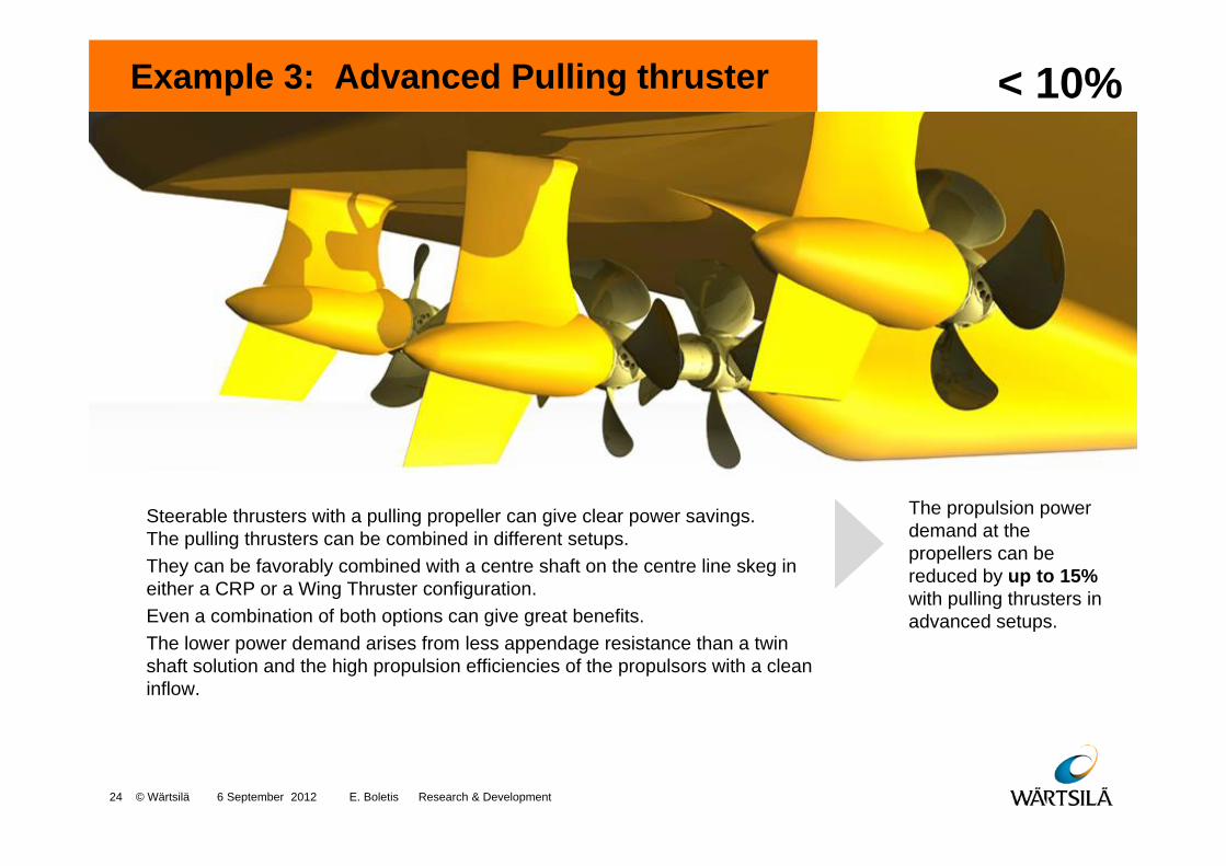
Example 3: Advanced Pulling thruster < 10%
Steerable thrusters with a pulling propeller can give clear power savings. The pulling thrusters can be combined in different setups. They can be favorably combined with a centre shaft on the centre line skeg in either a CRP or a Wing Thruster configuration. Even a combination of both options can give great benefits. The lower power demand arises from less appendage resistance than a twin shaft solution and the high propulsion efficiencies of the propulsors with a clean inflow.
The propulsion power demand at the propellers can be reduced by up to 15% with pulling thrusters in advanced setups.
6 September 2012 E. Boletis Research & Development 24 © Wärtsilä

Example 4: Wing Thrusters < 10%
Installing wing thrusters on twin screw vessels can achieve significant power savings, obtained mainly due to lower resistance from the hull appendages.The propulsion concept compares a centre line propeller and two wing thrusters with a twin shaft line arrangement.
Better ship performance in the range of 8% to 10%. More flexibility in the engine arrangement and more competitive ship performance.
6 September 2012 E. Boletis Research & Development 25 © Wärtsilä
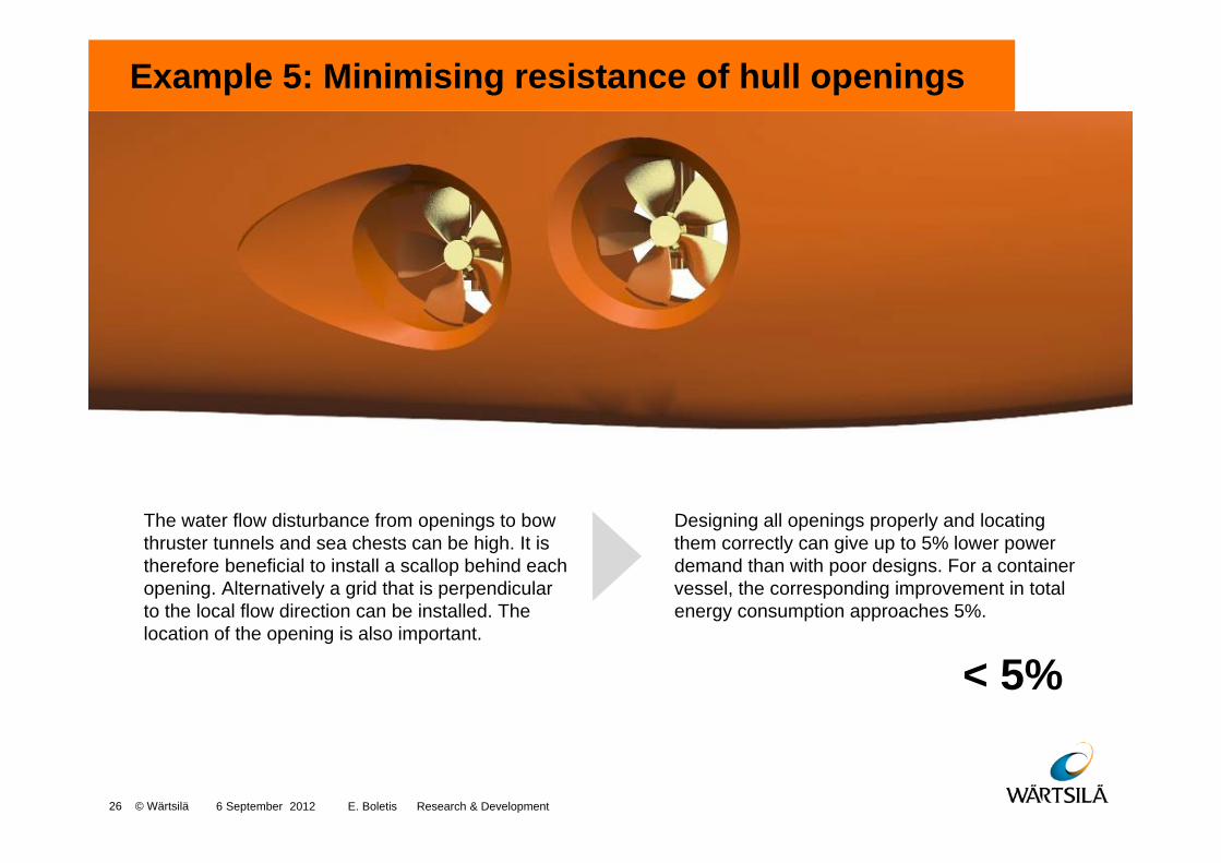
Example 5: Minimising resistance of hull openings
< 5%
The water flow disturbance from openings to bow thruster tunnels and sea chests can be high. It is therefore beneficial to install a scallop behind each opening. Alternatively a grid that is perpendicular to the local flow direction can be installed. The location of the opening is also important.
Designing all openings properly and locating them correctly can give up to 5% lower power demand than with poor designs. For a container vessel, the corresponding improvement in total energy consumption approaches 5%.
6 September 2012 E. Boletis Research & Development 26 © Wärtsilä

Example 6: Take care of Propeller surface finish/polishing
< 10%
Regular in-service polishing is required to reduce surface roughness on caused by propellers of every material organic growth and fouling. This can be done without disrupting service operation by using divers.
Up to 10% improvement in service propeller efficiency compared to a fouled propeller.
6 September 2012 E. Boletis Research & Development 27 © Wärtsilä
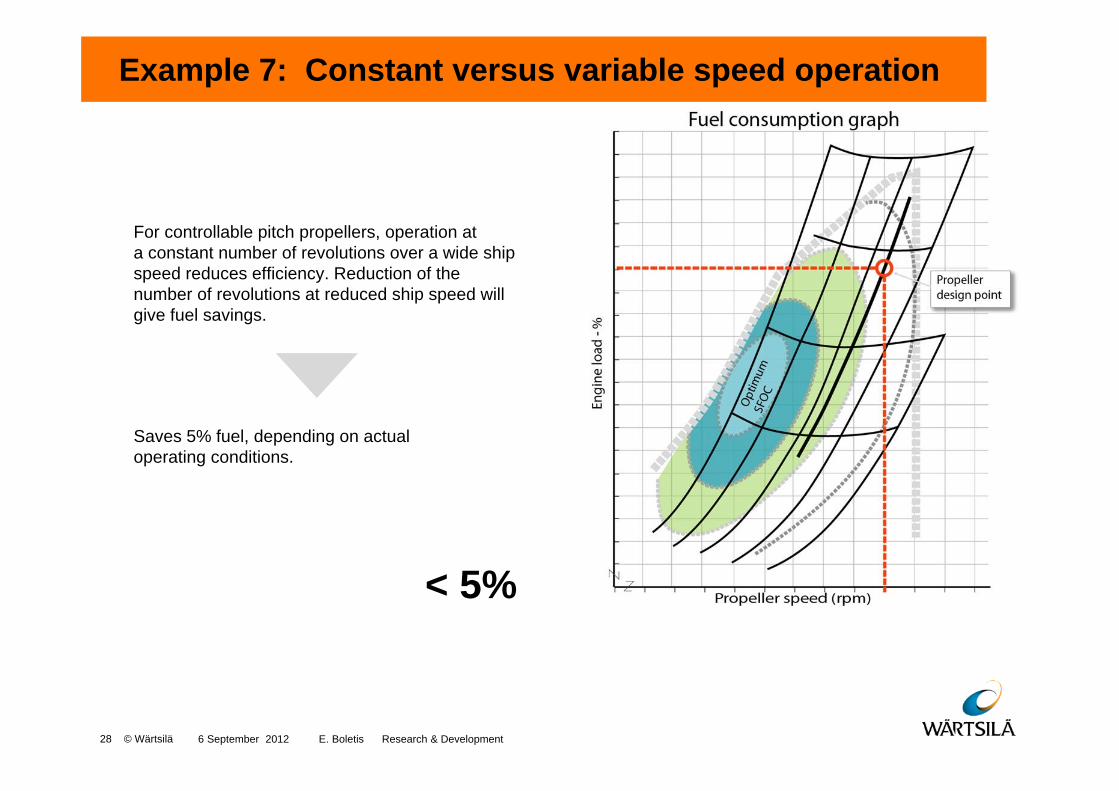
Example 7: Constant versus variable speed operation
< 5%
For controllable pitch propellers, operation at a constant number of revolutions over a wide ship speed reduces efficiency. Reduction of the number of revolutions at reduced ship speed will give fuel savings.
Saves 5% fuel, depending on actual operating conditions.
6 September 2012 E. Boletis Research & Development 28 © Wärtsilä
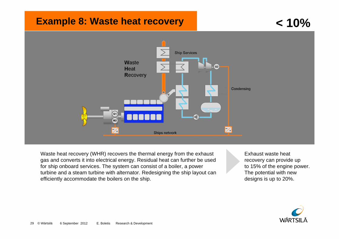
Example 8: Waste heat recovery < 10%
Waste heat recovery (WHR) recovers the thermal energy from the exhaust gas and converts it into electrical energy. Residual heat can further be used for ship onboard services. The system can consist of a boiler, a power turbine and a steam turbine with alternator. Redesigning the ship layout can efficiently accommodate the boilers on the ship.
Exhaust waste heat recovery can provide up to 15% of the engine power. The potential with new designs is up to 20%.
6 September 2012 E. Boletis Research & Development 29 © Wärtsilä
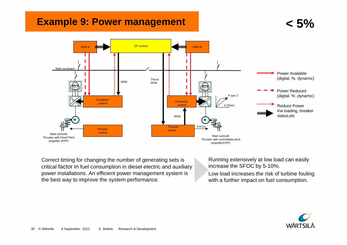
Example 9: Power management < 5%
Correct timing for changing the number of generating sets is critical factor in fuel consumption in diesel electric and auxiliary power installations. An efficient power management system is the best way to improve the system performance.
Running extensively at low load can easily increase the SFOC by 5-10%.Low load increases the risk of turbine fouling with a further impact on fuel consumption.
Power Available (digital, %, dynamic)
Power Reduced(digital, % ,dynamic)
Reduce PowerKw loading, breaker status,etc
M M
Main sw.board
Main azimuthThruster with Fixed Pitch
prppeller (FPP)
Main azimuthThruster with controllable pitch
propeller(CPP)
PMS A PMS B
Converter control Converter
control
Thruster control
Thrustercontrol
DP control
RPM
PITCH
ThrustRPM
RPM
P,rpm,T
0-20sec
6 September 2012 E. Boletis Research & Development 30 © Wärtsilä
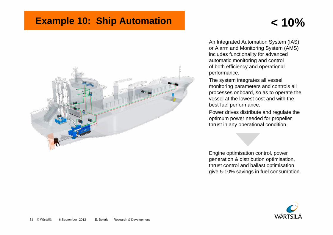
Example 10: Ship Automation < 10%An Integrated Automation System (IAS) or Alarm and Monitoring System (AMS) includes functionality for advanced automatic monitoring and control of both efficiency and operational performance. The system integrates all vessel monitoring parameters and controls all processes onboard, so as to operate the vessel at the lowest cost and with the best fuel performance.Power drives distribute and regulate the optimum power needed for propeller thrust in any operational condition.
Engine optimisation control, power generation & distribution optimisation, thrust control and ballast optimisation give 5-10% savings in fuel consumption.
6 September 2012 E. Boletis Research & Development 31 © Wärtsilä
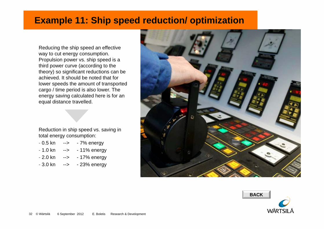
Example 11: Ship speed reduction/ optimization < 23%
Reducing the ship speed an effective way to cut energy consumption. Propulsion power vs. ship speed is a third power curve (according to the theory) so significant reductions can be achieved. It should be noted that for lower speeds the amount of transported cargo / time period is also lower. The energy saving calculated here is for an equal distance travelled.
Reduction in ship speed vs. saving in total energy consumption:- 0.5 kn --> - 7% energy- 1.0 kn --> - 11% energy- 2.0 kn --> - 17% energy- 3.0 kn --> - 23% energy
BACK
6 September 2012 E. Boletis Research & Development 32 © Wärtsilä
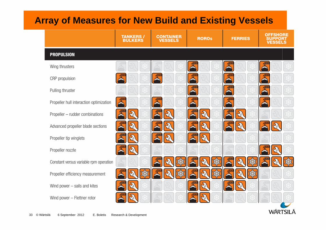
Array of Measures for New Build and Existing Vessels
6 September 2012 E. Boletis Research & Development 33 © Wärtsilä

34 © Wärtsilä
Concluding Remarks
- Fuel cost and environment are the drivers
- Large percent of shipping costis fuel (40% in many cases).
- A significant Fuel Saving Potential exists. It can reach up to 50% in some cases.
- We would need the combined Industry effort to take full advantage of such a Potential.
6 September 2012 E. Boletis Research & Development