· pdf file6/0 6 - sensors for pressure control selection guides . . . . . . . . . . . . . . ....
TRANSCRIPT
6/0
6 - Sensors for pressure control
Selection guides . . . . . . . . . . . . . . . . . . . . . . . . . . . . . . . . . . . . . . . . . . . . page 6/2
Electronic pressure sensors for control circuits
For controlling the pressure of air, water, hydraulic oils, corrosive fl uids
Nautilus® type XML G, without display
Presentation . . . . . . . . . . . . . . . . . . . . . . . . . . . . . . . . . . . . . . . . . . . . page 6/10Pressure transmitters with analogue output 4...20mA or 0...10 V . . . . page 6/12Pressure and vacuum switches with solid-state NPN or PNP output . page 6/16Accessories . . . . . . . . . . . . . . . . . . . . . . . . . . . . . . . . . . . . . . . . . . . . page 6/20
Nautilus® type XML E, without display
Presentation . . . . . . . . . . . . . . . . . . . . . . . . . . . . . . . . . . . . . . . . . . . . page 6/22Pressure transmitter with analogue output 4...20 mA . . . . . . . . . . . . . page 6/24Pressure and vacuum switches for regulation between 2 thresholds . page 6/28Accessories . . . . . . . . . . . . . . . . . . . . . . . . . . . . . . . . . . . . . . . . . . . . page 6/32
Nautilus® Universal, Osiconcept®, type XML F, with digital display
Presentation . . . . . . . . . . . . . . . . . . . . . . . . . . . . . . . . . . . . . . . . . . . . page 6/34Size - 1 bar to 600 bar . . . . . . . . . . . . . . . . . . . . . . . . . . . . . . . . . . . . page 6/36Accessories and replacement parts . . . . . . . . . . . . . . . . . . . . . . . . . . page 6/62
General . . . . . . . . . . . . . . . . . . . . . . . . . . . . . . . . . . . . . . . . . . . . . . . . . page 6/64
Electromechanical pressure and vacuum switches for control circuits
For controlling the pressure of air, water, hydraulic oils, corrosive fl uids and viscous products
Nautilus® type XML, presentation . . . . . . . . . . . . . . . . . . . . . . . . . . . . . page 6/68
For detection of a single treshold (fi xed differential)
Nautilus® type XML A . . . . . . . . . . . . . . . . . . . . . . . . . . . . . . . . . . . . . page 6/70
For regulation between 2 thresholds (adjustable differential)
Nautilus® type XML B . . . . . . . . . . . . . . . . . . . . . . . . . . . . . . . . . . . . page 6/71Nautilus® type XML C . . . . . . . . . . . . . . . . . . . . . . . . . . . . . . . . . . . . page 6/72
Dual stage, fi xed differential, for detection at each threshold
Nautilus® type XML D . . . . . . . . . . . . . . . . . . . . . . . . . . . . . . . . . . . . page 6/73
Accessories and replacement parts . . . . . . . . . . . . . . . . . . . . . . . . . . . page 6/122
Equivalent model references of XML and XM2 JM, XMJ and XMGpressure and vacuum switches . . . . . . . . . . . . . . . . . . . . . . . . . . . . . page 6/126
Components materials of switch in contact with the fl uid . . . . . . . . . . . page 6/128
For controlling the pressure of air, water, hydraulic oils and corrosive fl uids
For control regulation beween 2 thresholds, with adjustable differential
Types ACW and ADW, presentation . . . . . . . . . . . . . . . . . . . . . . . . . page 6/130Type ACW, size 0.7 to 131 bar . . . . . . . . . . . . . . . . . . . . . . . . . . . . . page 6/132Type ADW, size 69 to 340 bar . . . . . . . . . . . . . . . . . . . . . . . . . . . . . . page 6/134
For controlling the pressure of air and water
For control regulation beween 2 thresholds, with adjustable differential
Types XMX and XMA, presentation . . . . . . . . . . . . . . . . . . . . . . . . . page 6/138Types XMX and XMA, sizes 6 to 25 bar . . . . . . . . . . . . . . . . . . . . . . page 6/140Accessories and replacement parts for XMX and XMA . . . . . . . . . . page 6/142
b
v
v
v
v
b
v
v
v
v
b
v
v
v
b
b
b
v
b
v
v
b
v
b
b
b
b
v
v
v
b
v
v
v
6/0
Contents 0
1
2
3
4
5
6
7
8
9
10
1
2
3
4
5
6
7
8
9
10
1
2
3
4
5
6
7
8
9
10
6/1
Electromechanical pressure switches for power circuits
For controlling the pressure of water
Types FTG, FSG and FYGPresentation. . . . . . . . . . . . . . . . . . . . . . . . . . . . . . . . . . . . . . . . . . . . . page 6/144
For detection of a sigle threshold with fi xed differential
Type FTG, size 4.6 bar . . . . . . . . . . . . . . . . . . . . . . . . . . . . . . . . . . . page 6/146
For regulation between 2 thresholds with adjustable differential
Type FSG, size 4.6 bar . . . . . . . . . . . . . . . . . . . . . . . . . . . . . . . . . . . page 6/147Type FSG NE, size 4.6 bar . . . . . . . . . . . . . . . . . . . . . . . . . . . . . . . . page 6/148Type FYG, sizes 7 and 10.5 bar . . . . . . . . . . . . . . . . . . . . . . . . . . . . page 6/149
For controlling the pressure of air and water
For regulation between 2 thresholds with adjustable differential
Type XMP, presentation . . . . . . . . . . . . . . . . . . . . . . . . . . . . . . . . . . page 6/152Type XMP, IP 54, sizes 6 to 25 bar . . . . . . . . . . . . . . . . . . . . . . . . . . page 6/154Type XMP, IP 65, sizes 6 to 25 bar . . . . . . . . . . . . . . . . . . . . . . . . . . page 6/160Accessories and replacement parts for XMP . . . . . . . . . . . . . . . . . . page 6/162
Electromechanical pressure and vacuum switchesNautilus®
General . . . . . . . . . . . . . . . . . . . . . . . . . . . . . . . . . . . . . . . . . . . . . . page 6/164Operating curves . . . . . . . . . . . . . . . . . . . . . . . . . . . . . . . . . . . . . . . page 6/170
b
b
v
b
v
v
v
b
v
v
v
v
b
v
v
1
2
3
4
5
6
7
8
9
10
1
2
3
4
5
6
7
8
9
10
1
2
3
4
5
6
7
8
9
10
6/2
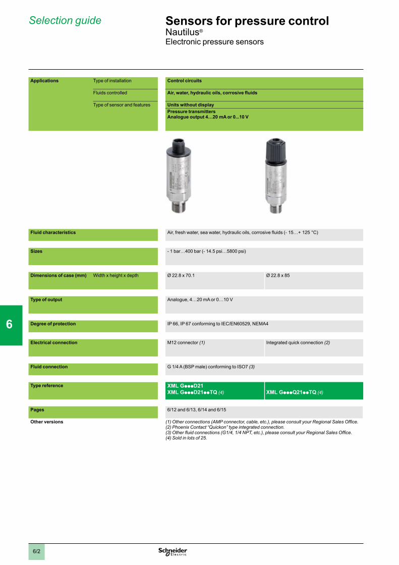
Selection guide
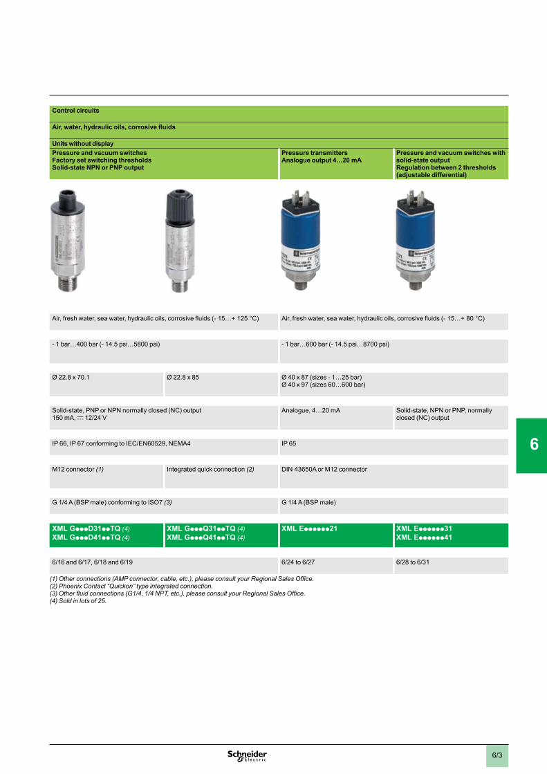
Control circuits
Air, water, hydraulic oils, corrosive fluids
Units without displayPressure and vacuum switches Factory set switching thresholdsSolid-state NPN or PNP output
Pressure transmittersAnalogue output 4…20 mA
Pressure and vacuum switches with solid-state outputRegulation between 2 thresholds (adjustable differential)
Air, fresh water, sea water, hydraulic oils, corrosive fluids (- 15…+ 125 °C) Air, fresh water, sea water, hydraulic oils, corrosive fluids (- 15…+ 80 °C)
- 1 bar…400 bar (- 14.5 psi…5800 psi) - 1 bar…600 bar (- 14.5 psi…8700 psi)
Ø 22.8 x 70.1 Ø 22.8 x 85 Ø 40 x 87 (sizes - 1…25 bar)Ø 40 x 97 (sizes 60…600 bar)
Solid-state, PNP or NPN normally closed (NC) output 150 mA, c 12/24 V
Analogue, 4…20 mA Solid-state, NPN or PNP, normally closed (NC) output
IP 66, IP 67 conforming to IEC/EN60529, NEMA4 IP 65
M12 connector (1) Integrated quick connection (2) DIN 43650A or M12 connector
G 1/4 A (BSP male) conforming to ISO7 (3) G 1/4 A (BSP male)
XML GpppD31ppTQ (4) XML GpppD41ppTQ (4)
XML GpppQ31ppTQ (4) XML GpppQ41ppTQ (4)
XML Epppppp21 XML Epppppp31 XML Epppppp41
6/16 and 6/17, 6/18 and 6/19 6/24 to 6/27 6/28 to 6/31
(1)Otherconnections(AMPconnector,cable,etc.),pleaseconsultyourRegionalSalesOffice.(2) Phoenix Contact “Quickon” type integrated connection.(3)Otherfluidconnections(G1/4,1/4NPT,etc.),pleaseconsultyourRegionalSalesOffice.(4) Sold in lots of 25.
Applications Type of installation Control circuits
Fluids controlled Air, water, hydraulic oils, corrosive fluids
Type of sensor and features Units without displayPressure transmitters Analogue output 4…20 mA or 0...10 V
Fluid characteristics Air, fresh water, sea water, hydraulic oils, corrosive fluids (- 15…+ 125 °C)
Sizes - 1 bar…400 bar (- 14.5 psi…5800 psi)
Dimensions of case (mm) Width x height x depth Ø 22.8 x 70.1 Ø 22.8 x 85
Type of output Analogue, 4…20 mA or 0…10 V
Degree of protection IP 66, IP 67 conforming to IEC/EN60529, NEMA4
Electrical connection M12 connector (1) Integrated quick connection (2)
Fluid connection G 1/4 A (BSP male) conforming to ISO7 (3)
Type reference XML GpppD21XML GpppD21ppTQ (4)
XML GpppQ21ppTQ (4)
Pages 6/12 and 6/13, 6/14 and 6/15
Other versions (1)Otherconnections(AMPconnector,cable,etc.),pleaseconsultyourRegionalSalesOffice.(2) Phoenix Contact “Quickon” type integrated connection.(3)Otherfluidconnections(G1/4,1/4NPT,etc.),pleaseconsultyourRegionalSalesOffice.(4) Sold in lots of 25.
Sensors for pressure control 0 Nautilus®
Electronic pressure sensors
1
2
3
4
5
6
7
8
9
10
6/3
Control circuits
Air, water, hydraulic oils, corrosive fluids
Units without displayPressure and vacuum switches Factory set switching thresholdsSolid-state NPN or PNP output
Pressure transmittersAnalogue output 4…20 mA
Pressure and vacuum switches with solid-state outputRegulation between 2 thresholds (adjustable differential)
Air, fresh water, sea water, hydraulic oils, corrosive fluids (- 15…+ 125 °C) Air, fresh water, sea water, hydraulic oils, corrosive fluids (- 15…+ 80 °C)
- 1 bar…400 bar (- 14.5 psi…5800 psi) - 1 bar…600 bar (- 14.5 psi…8700 psi)
Ø 22.8 x 70.1 Ø 22.8 x 85 Ø 40 x 87 (sizes - 1…25 bar)Ø 40 x 97 (sizes 60…600 bar)
Solid-state, PNP or NPN normally closed (NC) output 150 mA, c 12/24 V
Analogue, 4…20 mA Solid-state, NPN or PNP, normally closed (NC) output
IP 66, IP 67 conforming to IEC/EN60529, NEMA4 IP 65
M12 connector (1) Integrated quick connection (2) DIN 43650A or M12 connector
G 1/4 A (BSP male) conforming to ISO7 (3) G 1/4 A (BSP male)
XML GpppD31ppTQ (4) XML GpppD41ppTQ (4)
XML GpppQ31ppTQ (4) XML GpppQ41ppTQ (4)
XML Epppppp21 XML Epppppp31 XML Epppppp41
6/16 and 6/17, 6/18 and 6/19 6/24 to 6/27 6/28 to 6/31
(1)Otherconnections(AMPconnector,cable,etc.),pleaseconsultyourRegionalSalesOffice.(2) Phoenix Contact “Quickon” type integrated connection.(3)Otherfluidconnections(G1/4,1/4NPT,etc.),pleaseconsultyourRegionalSalesOffice.(4) Sold in lots of 25.
0
Applications Type of installation Control circuits
Fluids controlled Air, water, hydraulic oils, corrosive fluids
Type of sensor and features Units without displayPressure transmitters Analogue output 4…20 mA or 0...10 V
Fluid characteristics Air, fresh water, sea water, hydraulic oils, corrosive fluids (- 15…+ 125 °C)
Sizes - 1 bar…400 bar (- 14.5 psi…5800 psi)
Dimensions of case (mm) Width x height x depth Ø 22.8 x 70.1 Ø 22.8 x 85
Type of output Analogue, 4…20 mA or 0…10 V
Degree of protection IP 66, IP 67 conforming to IEC/EN60529, NEMA4
Electrical connection M12 connector (1) Integrated quick connection (2)
Fluid connection G 1/4 A (BSP male) conforming to ISO7 (3)
Type reference XML GpppD21XML GpppD21ppTQ (4)
XML GpppQ21ppTQ (4)
Pages 6/12 and 6/13, 6/14 and 6/15
Other versions (1)Otherconnections(AMPconnector,cable,etc.),pleaseconsultyourRegionalSalesOffice.(2) Phoenix Contact “Quickon” type integrated connection.(3)Otherfluidconnections(G1/4,1/4NPT,etc.),pleaseconsultyourRegionalSalesOffice.(4) Sold in lots of 25.
1
2
3
4
5
6
7
8
9
10
6/4
Selection guide
Control circuits
Air, water, hydraulic oils, corrosive fluids
Configurable units with digital displayUniversal sensorsRegulation between 2 thresholds (adjustable differential)
Configurable units with digital displayUniversal sensorsRegulation between 2 thresholds (adjustable differential)
Configurable units with digital displayPressure and vacuum switches with 2.5 A relay outputsRegulation between 2 thresholds (adjustable differential)
Configurable units with digital displayDual stage pressure and vacuum switches (solid-state outputs)Detection of 2 thresholds and adjustable differential for each thresholdSolid-state and analogue output
current 4…20 mASolid-state and analogue output voltage 0…10 V
Air, fresh water, sea water, hydraulic oils, corrosive fluids (- 15…+ 80 °C)
- 1 bar…600 bar (- 14.5 psi…8700 psi)
46 x 113 x 58 46 x 119 x 58 46 x 113 x 58
Solid-state, PNP or NPN, 200 mA, c 24 V outputAnalogue output 4…20 mA
Solid-state, PNP or NPN, 200 mA, c 24 V outputAnalogue output 0…10 V
Relay output 2.5 A, a 120 V
2 solid-state, PNP or NPN, 200 mA, c 24 V outputs
IP 67
M12 connector, “Snap-C” compatible SAE 7/8-16UN connector M12 connector, “Snap-C” compatible
G 1/4 A (BSP) or 1/4 NPT or SAE 7/16-20UNF female
XML FpppD202p XML FpppD212p XML FpppE204p XML FpppD203p
6/36 to 6/61
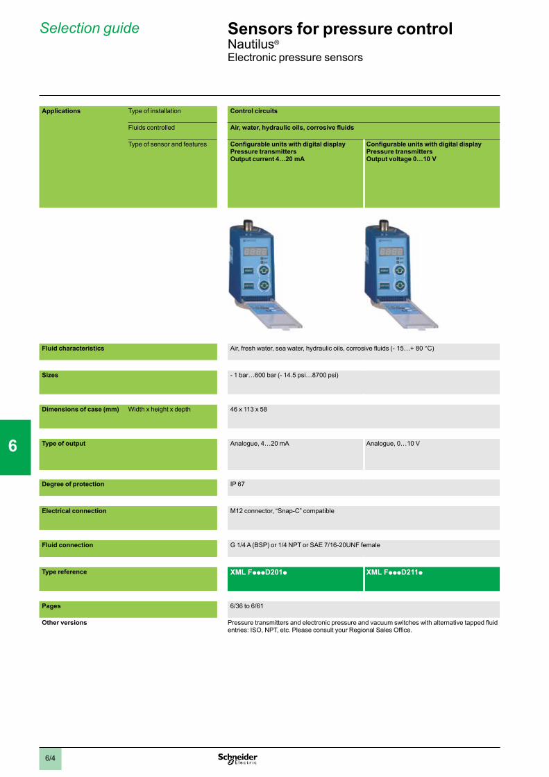
Applications Type of installation Control circuits
Fluids controlled Air, water, hydraulic oils, corrosive fluids
Type of sensor and features Configurable units with digital displayPressure transmittersOutput current 4…20 mA
Configurable units with digital displayPressure transmittersOutput voltage 0…10 V
Fluid characteristics Air, fresh water, sea water, hydraulic oils, corrosive fluids (- 15…+ 80 °C)
Sizes - 1 bar…600 bar (- 14.5 psi…8700 psi)
Dimensions of case (mm) Width x height x depth 46 x 113 x 58
Type of output Analogue, 4…20 mA Analogue, 0…10 V
Degree of protection IP 67
Electrical connection M12 connector, “Snap-C” compatible
Fluid connection G 1/4 A (BSP) or 1/4 NPT or SAE 7/16-20UNF female
Type reference XML FpppD201p XML FpppD211p
Pages 6/36 to 6/61
Other versions Pressure transmitters and electronic pressure and vacuum switches with alternative tapped fluid entries: ISO, NPT, etc. Please consult your Regional Sales Office.
Sensors for pressure control 0 Nautilus®
Electronic pressure sensors
1
2
3
4
5
6
7
8
9
10

6/5
Control circuits
Air, water, hydraulic oils, corrosive fluids
Configurable units with digital displayUniversal sensorsRegulation between 2 thresholds (adjustable differential)
Configurable units with digital displayUniversal sensorsRegulation between 2 thresholds (adjustable differential)
Configurable units with digital displayPressure and vacuum switches with 2.5 A relay outputsRegulation between 2 thresholds (adjustable differential)
Configurable units with digital displayDual stage pressure and vacuum switches (solid-state outputs)Detection of 2 thresholds and adjustable differential for each thresholdSolid-state and analogue output
current 4…20 mASolid-state and analogue output voltage 0…10 V
Air, fresh water, sea water, hydraulic oils, corrosive fluids (- 15…+ 80 °C)
- 1 bar…600 bar (- 14.5 psi…8700 psi)
46 x 113 x 58 46 x 119 x 58 46 x 113 x 58
Solid-state, PNP or NPN, 200 mA, c 24 V outputAnalogue output 4…20 mA
Solid-state, PNP or NPN, 200 mA, c 24 V outputAnalogue output 0…10 V
Relay output 2.5 A, a 120 V
2 solid-state, PNP or NPN, 200 mA, c 24 V outputs
IP 67
M12 connector, “Snap-C” compatible SAE 7/8-16UN connector M12 connector, “Snap-C” compatible
G 1/4 A (BSP) or 1/4 NPT or SAE 7/16-20UNF female
XML FpppD202p XML FpppD212p XML FpppE204p XML FpppD203p
6/36 to 6/61
0
Applications Type of installation Control circuits
Fluids controlled Air, water, hydraulic oils, corrosive fluids
Type of sensor and features Configurable units with digital displayPressure transmittersOutput current 4…20 mA
Configurable units with digital displayPressure transmittersOutput voltage 0…10 V
Fluid characteristics Air, fresh water, sea water, hydraulic oils, corrosive fluids (- 15…+ 80 °C)
Sizes - 1 bar…600 bar (- 14.5 psi…8700 psi)
Dimensions of case (mm) Width x height x depth 46 x 113 x 58
Type of output Analogue, 4…20 mA Analogue, 0…10 V
Degree of protection IP 67
Electrical connection M12 connector, “Snap-C” compatible
Fluid connection G 1/4 A (BSP) or 1/4 NPT or SAE 7/16-20UNF female
Type reference XML FpppD201p XML FpppD211p
Pages 6/36 to 6/61
Other versions Pressure transmitters and electronic pressure and vacuum switches with alternative tapped fluid entries: ISO, NPT, etc. Please consult your Regional Sales Office.
1
2
3
4
5
6
7
8
9
10
6/6
Selection guide
Control circuits
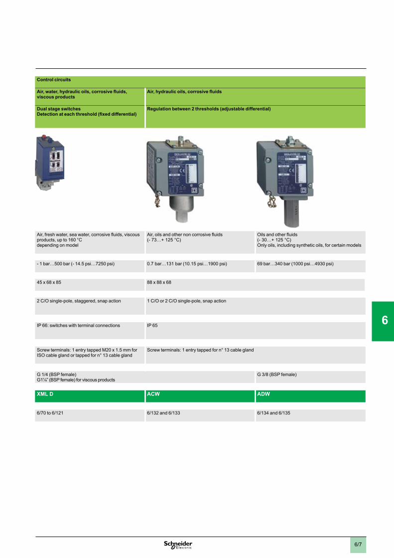
Air, water, hydraulic oils, corrosive fluids, viscous products
Air, hydraulic oils, corrosive fluids
Dual stage switches Detection at each threshold (fixed differential)
Regulation between 2 thresholds (adjustable differential)
Air, fresh water, sea water, corrosive fluids, viscous products, up to 160 °C depending on model
Air, oils and other non corrosive fluids (- 73…+ 125 °C)
Oils and other fluids (- 30…+ 125 °C)Only oils, including synthetic oils, for certain models
- 1 bar…500 bar (- 14.5 psi…7250 psi) 0.7 bar…131 bar (10.15 psi…1900 psi) 69 bar…340 bar (1000 psi…4930 psi)
45 x 68 x 85 88 x 88 x 68
2 C/O single-pole, staggered, snap action 1 C/O or 2 C/O single-pole, snap action
IP 66: switches with terminal connections IP 65
Screw terminals: 1 entry tapped M20 x 1.5 mm for ISO cable gland or tapped for n° 13 cable gland
Screw terminals: 1 entry tapped for n° 13 cable gland
G 1/4 (BSP female)G1¼” (BSP female) for viscous products
G 3/8 (BSP female)
XML D ACW ADW
6/70 to 6/121 6/132 and 6/133 6/134 and 6/135
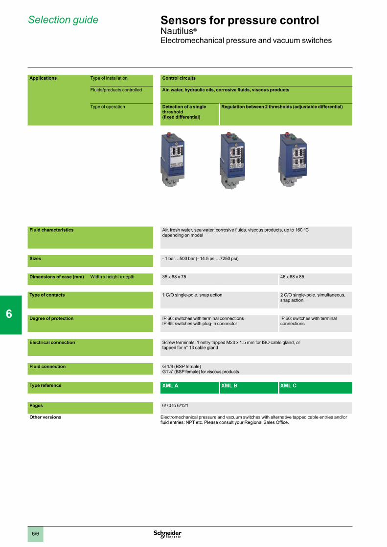
Applications Type of installation Control circuits
Fluids/products controlled Air, water, hydraulic oils, corrosive fluids, viscous products
Type of operation Detection of a single threshold (fixed differential)
Regulation between 2 thresholds (adjustable differential)
Fluid characteristics Air, fresh water, sea water, corrosive fluids, viscous products, up to 160 °C depending on model
Sizes - 1 bar…500 bar (- 14.5 psi…7250 psi)
Dimensions of case (mm) Width x height x depth 35 x 68 x 75 46 x 68 x 85
Type of contacts 1 C/O single-pole, snap action 2 C/O single-pole, simultaneous, snap action
Degree of protection IP 66: switches with terminal connectionsIP 65: switches with plug-in connector
IP 66: switches with terminal connections
Electrical connection Screw terminals: 1 entry tapped M20 x 1.5 mm for ISO cable gland, or tapped for n° 13 cable gland
Fluid connection G 1/4 (BSP female)G1¼” (BSP female) for viscous products
Type reference XML A XML B XML C
Pages 6/70 to 6/121
Other versions Electromechanical pressure and vacuum switches with alternative tapped cable entries and/or fluid entries: NPT etc. Please consult your Regional Sales Office.
Sensors for pressure control 0 Nautilus®
Electromechanical pressure and vacuum switches
1
2
3
4
5
6
7
8
9
10
6/7
Control circuits
Air, water, hydraulic oils, corrosive fluids, viscous products
Air, hydraulic oils, corrosive fluids
Dual stage switches Detection at each threshold (fixed differential)
Regulation between 2 thresholds (adjustable differential)
Air, fresh water, sea water, corrosive fluids, viscous products, up to 160 °C depending on model
Air, oils and other non corrosive fluids (- 73…+ 125 °C)
Oils and other fluids (- 30…+ 125 °C)Only oils, including synthetic oils, for certain models
- 1 bar…500 bar (- 14.5 psi…7250 psi) 0.7 bar…131 bar (10.15 psi…1900 psi) 69 bar…340 bar (1000 psi…4930 psi)
45 x 68 x 85 88 x 88 x 68
2 C/O single-pole, staggered, snap action 1 C/O or 2 C/O single-pole, snap action
IP 66: switches with terminal connections IP 65
Screw terminals: 1 entry tapped M20 x 1.5 mm for ISO cable gland or tapped for n° 13 cable gland
Screw terminals: 1 entry tapped for n° 13 cable gland
G 1/4 (BSP female)G1¼” (BSP female) for viscous products
G 3/8 (BSP female)
XML D ACW ADW
6/70 to 6/121 6/132 and 6/133 6/134 and 6/135
0
Applications Type of installation Control circuits
Fluids/products controlled Air, water, hydraulic oils, corrosive fluids, viscous products
Type of operation Detection of a single threshold (fixed differential)
Regulation between 2 thresholds (adjustable differential)
Fluid characteristics Air, fresh water, sea water, corrosive fluids, viscous products, up to 160 °C depending on model
Sizes - 1 bar…500 bar (- 14.5 psi…7250 psi)
Dimensions of case (mm) Width x height x depth 35 x 68 x 75 46 x 68 x 85
Type of contacts 1 C/O single-pole, snap action 2 C/O single-pole, simultaneous, snap action
Degree of protection IP 66: switches with terminal connectionsIP 65: switches with plug-in connector
IP 66: switches with terminal connections
Electrical connection Screw terminals: 1 entry tapped M20 x 1.5 mm for ISO cable gland, or tapped for n° 13 cable gland
Fluid connection G 1/4 (BSP female)G1¼” (BSP female) for viscous products
Type reference XML A XML B XML C
Pages 6/70 to 6/121
Other versions Electromechanical pressure and vacuum switches with alternative tapped cable entries and/or fluid entries: NPT etc. Please consult your Regional Sales Office.
1
2
3
4
5
6
7
8
9
10

6/8
Power circuits
Water Air, water
Detection of a single threshold (fixed differential)
Regulation between 2 thresholds (adjustable differential)
Fresh water, sea water (0…+ 70 °C) Air, fresh water, sea water (0…+ 70 °C)
4.6 bar (66.7 psi) 7 bar and 10.5 bar (101.5 psi and 152.3 psi)
6 bar, 12 bar and 25 bar (87 psi, 174 psi and 362.5 psi)
72 x 73 x 102 72 x 77 x 106 72 x 73 x 102 57 x 78 x 97.5
Internal screws
2 N/C snap action 2 N/C or 3 N/C snap action
IP 20 IP 65 IP 20 IP 54 or IP 65 depending on model
Screw terminals: 2 cable entries, with grommet Screw terminals: 2 entries incorporating n° 13 cable gland
Screw terminals: 2 cable entries, with grommet
Screw terminals: 2 entries incorporating n° 13 cable gland or without cable gland, depending on model
G 1/4 or R 1/4 (BSP female or BSP male) G 1/4 (BSP female) G 1/4, G 3/8 or 4 x G 1/4 (BSP female) depending on model
FTG FSG p FSG 2NE FYG XMP
6/146 6/147 6/148 6/149 6/154 to 6/161
Applications Type of installation Control circuits
Fluids controlled Air, water
Type of operation Regulation between 2 thresholds (adjustable differential)
Fluid characteristics Air, fresh water, sea water (0…+ 70 °C)
Sizes 6 bar, 12 bar and 25 bar (87 psi, 174 psi and 362.5 psi)
Dimensions of case (mm) Width x height x depth 57 x 78 x 97.5
Setting of switching points Internal screws External screws
Type of contacts 1 C/O single-pole, snap action
Degree of protection IP 54
Electrical connection Screw terminals: 2 entries tapped for n° 13 cable gland, one fitted with n° 13 cable gland, one fitted with blanking plug
Fluid connection G 1/4 or 4 x G 1/4 (BSP female) depending on model
Type reference XMX XMA
Page(s) 6/140 6/141
Other versions Electromechanical pressure switches with alternative tapped cable entries and/or fluid entries: ISO, NPT, etc. Please consult your Regional Sales Office.
Sensors for pressure control 0 Nautilus®
Electromechanical pressure switches
Selection guideSelection guide
1
2
3
4
5
6
7
8
9
10

6/9
Power circuits
Water Air, water
Detection of a single threshold (fixed differential)
Regulation between 2 thresholds (adjustable differential)
Fresh water, sea water (0…+ 70 °C) Air, fresh water, sea water (0…+ 70 °C)
4.6 bar (66.7 psi) 7 bar and 10.5 bar (101.5 psi and 152.3 psi)
6 bar, 12 bar and 25 bar (87 psi, 174 psi and 362.5 psi)
72 x 73 x 102 72 x 77 x 106 72 x 73 x 102 57 x 78 x 97.5
Internal screws
2 N/C snap action 2 N/C or 3 N/C snap action
IP 20 IP 65 IP 20 IP 54 or IP 65 depending on model
Screw terminals: 2 cable entries, with grommet Screw terminals: 2 entries incorporating n° 13 cable gland
Screw terminals: 2 cable entries, with grommet
Screw terminals: 2 entries incorporating n° 13 cable gland or without cable gland, depending on model
G 1/4 or R 1/4 (BSP female or BSP male) G 1/4 (BSP female) G 1/4, G 3/8 or 4 x G 1/4 (BSP female) depending on model
FTG FSG p FSG 2NE FYG XMP
6/146 6/147 6/148 6/149 6/154 to 6/161
0
Applications Type of installation Control circuits
Fluids controlled Air, water
Type of operation Regulation between 2 thresholds (adjustable differential)
Fluid characteristics Air, fresh water, sea water (0…+ 70 °C)
Sizes 6 bar, 12 bar and 25 bar (87 psi, 174 psi and 362.5 psi)
Dimensions of case (mm) Width x height x depth 57 x 78 x 97.5
Setting of switching points Internal screws External screws
Type of contacts 1 C/O single-pole, snap action
Degree of protection IP 54
Electrical connection Screw terminals: 2 entries tapped for n° 13 cable gland, one fitted with n° 13 cable gland, one fitted with blanking plug
Fluid connection G 1/4 or 4 x G 1/4 (BSP female) depending on model
Type reference XMX XMA
Page(s) 6/140 6/141
Other versions Electromechanical pressure switches with alternative tapped cable entries and/or fluid entries: ISO, NPT, etc. Please consult your Regional Sales Office.
1
2
3
4
5
6
7
8
9
10
6/10
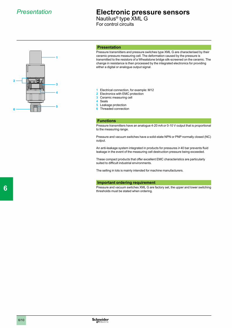
Presentation
PresentationPressure transmitters and pressure switches type XML G are characterised by their ceramic pressure measuring cell. The deformation caused by the pressure is transmitted to the resistors of a Wheatstone bridge silk-screened on the ceramic. The change in resistance is then processed by the integrated electronics for providing either a digital or analogue output signal.
1 Electrical connection, for example: M122 Electronics with EMC protection 3 Ceramic measuring cell4 Seals5 Leakage protection6 Threaded connection
FunctionsPressure transmitters have an analogue 4-20 mA or 0-10 V output that is proportional to the measuring range.
Pressure and vacuum switches have a solid-state NPN or PNP normally closed (NC) output.
An anti-leakage system integrated in products for pressures u 40 bar prevents fluid leakage in the event of the measuring cell destruction pressure being exceeded.
These compact products that offer excellent EMC characteristics are particularly suited to difficult industrial environments.
The selling in lots is mainly intended for machine manufacturers.
Important ordering requirementPressure and vacuum switches XML G are factory set, the upper and lower switching thresholds must be stated when ordering.
65
4
3
1
2
65
4
3
1
2
Electronic pressure sensors 0 Nautilus® type XML GFor control circuits
1
2
3
4
5
6
7
8
9
10
6/11
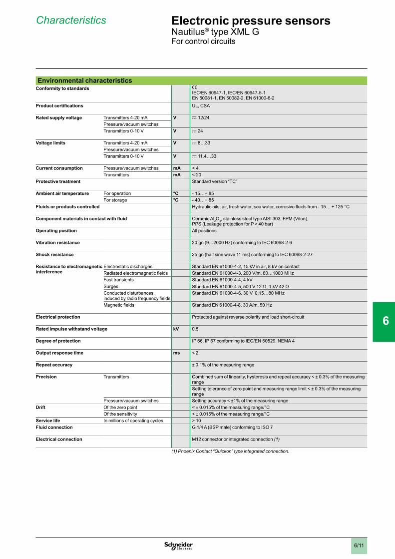
Characteristics
Environmental characteristicsConformity to standards e
IEC/EN 60947-1, IEC/EN 60947-5-1EN 50081-1, EN 50082-2, EN 61000-6-2
Product certifications UL, CSA
Rated supply voltage Transmitters 4-20 mA V c 12/24Pressure/vacuum switchesTransmitters 0-10 V V c 24
Voltage limits Transmitters 4-20 mA V c 8…33Pressure/vacuum switchesTransmitters 0-10 V V c 11.4…33
Current consumption Pressure/vacuum switches mA < 4 Transmitters mA < 20
Protective treatment Standard version “TC”
Ambient air temperature For operation °C - 15…+ 85For storage °C - 40…+ 85
Fluids or products controlled Hydraulic oils, air, fresh water, sea water, corrosive fluids from - 15… + 125 °C
Component materials in contact with fluid Ceramic Al2O3, stainless steel type AISI 303, FPM (Viton), PPS (Leakage protection for P > 40 bar)
Operating position All positions
Vibration resistance 20 gn (9…2000 Hz) conforming to IEC 60068-2-6
Shock resistance 25 gn (half sine wave 11 ms) conforming to IEC 60068-2-27
Resistance to electromagnetic interference
Electrostatic discharges Standard EN 61000-4-2, 15 kV in air, 8 kV on contactRadiated electromagnetic fields Standard EN 61000-4-3, 200 V/m, 80…1000 MHzFast transients Standard EN 61000-4-4, 4 kVSurges Standard EN 61000-4-5, 500 V 12 W, 1 kV 42 W Conducted disturbances, induced by radio frequency fields
Standard EN 61000-4-6, 30 V 0.15…80 MHz
Magnetic fields Standard EN 61000-4-8, 30 A/m, 50 Hz
Electrical protection Protected against reverse polarity and load short-circuit
Rated impulse withstand voltage kV 0.5
Degree of protection IP 66, IP 67 conforming to IEC/EN 60529, NEMA 4
Output response time ms < 2
Repeat accuracy ± 0.1% of the measuring range
Precision Transmitters Combined sum of linearity, hysteresis and repeat accuracy < ± 0.3% of the measuring rangeSetting tolerance of zero point and measuring range limit < ± 0.3% of the measuring range
Pressure/vacuum switches Setting accuracy < ±1% of the measuring rangeDrift Of the zero point < ± 0.015% of the measuring range/°C
Of the sensitivity < ± 0.015% of the measuring range/°CService life In millions of operating cycles > 10Fluid connection G 1/4 A (BSP male) conforming to ISO 7
Electrical connection M12 connector or integrated connection (1)
(1) Phoenix Contact “Quickon” type integrated connection.
Electronic pressure sensors 0 Nautilus® type XML GFor control circuits
1
2
3
4
5
6
7
8
9
10
6/12
References, characteristics
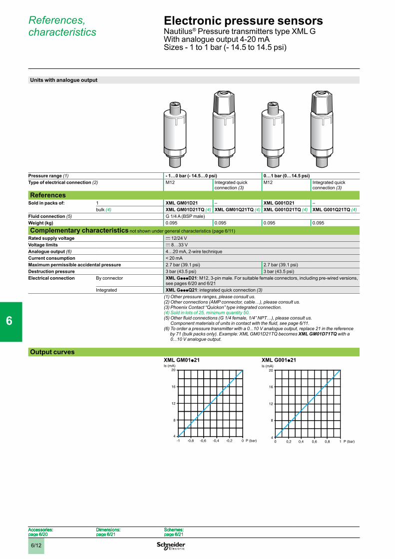
Units with analogue output
Pressure range (1) - 1…0 bar (- 14.5…0 psi) 0…1 bar (0…14.5 psi)Type of electrical connection (2) M12 Integrated quick
connection (3)M12 Integrated quick
connection (3)
ReferencesSold in packs of: 1 XML GM01D21 – XML G001D21 –
bulk (4) XML GM01D21TQ (4) XML GM01Q21TQ (4) XML G001D21TQ (4) XML G001Q21TQ (4)Fluid connection (5) G 1/4 A (BSP male)Weight (kg) 0.095 0.095 0.095 0.095
Complementary characteristics not shown under general characteristics (page 6/11)Rated supply voltage c 12/24 VVoltage limits c 8…33 VAnalogue output (6) 4…20 mA, 2-wire techniqueCurrent consumption < 20 mAMaximum permissible accidental pressure 2.7 bar (39.1 psi) 2.7 bar (39.1 psi)Destruction pressure 3 bar (43.5 psi) 3 bar (43.5 psi)Electrical connection By connector XML GpppD21: M12, 3-pin male. For suitable female connectors, including pre-wired versions,
see pages 6/20 and 6/21 Integrated XML GpppQ21: integrated quick connection (3)
(1) Other pressure ranges, please consult us.(2) Other connections (AMP connector, cable…), please consult us.(3) Phoenix Contact “Quickon” type integrated connection.(4) Sold in lots of 25, minimum quantity 50.(5)Otherfluidconnections(G1/4female,1/4”NPT…),pleaseconsultus.
Componentmaterialsofunitsincontactwiththefluid,seepage6/11.(6)Toorderapressuretransmitterwitha0...10Vanalogueoutput,replace21inthereferenceby71(bulkpacksonly).Example:XMLGM01D21TQbecomesXML GM01D71TQ with a
0...10Vanalogueoutput.
Output curvesXML GM01p21 XML G001p21 Is (mA)
-1 0 P (bar)-0,8 -0,2-0,4-0,6
20
16
12
8
4
Is (mA)
-1 0 P (bar)-0,8 -0,2-0,4-0,6
20
16
12
8
4
0,2 0,80,60,4
Is (mA)20
16
8
12
40 1 P (bar)0,2 0,80,60,4
Is (mA)20
16
8
12
40 1 P (bar)
Accessories:page 6/20
Dimensions:page 6/21
Schemes:page 6/21
Accessories:page 6/20
Dimensions:page 6/21
Schemes:page 6/21
Accessories:page 6/20
Dimensions:page 6/21
Schemes:page 6/21
Accessories:page 6/20
Dimensions:page 6/21
Schemes:page 6/21
Electronic pressure sensors 0 Nautilus® Pressure transmitters type XML G With analogue output 4-20 mASizes - 1 to 1 bar (- 14.5 to 14.5 psi)
1
2
3
4
5
6
7
8
9
10
6/13
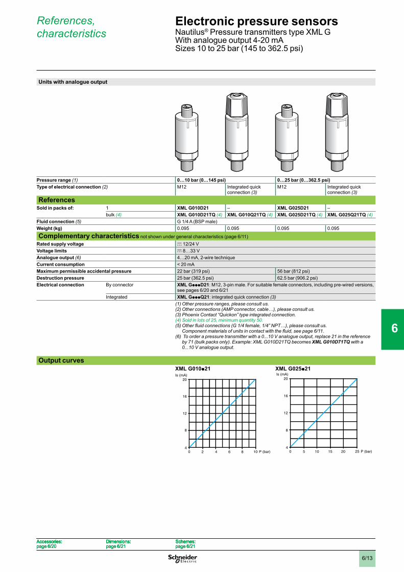
References, characteristics
Units with analogue output
Pressure range (1) 0…10 bar (0…145 psi) 0…25 bar (0…362.5 psi)Type of electrical connection (2) M12 Integrated quick
connection (3)M12 Integrated quick
connection (3)
ReferencesSold in packs of: 1 XML G010D21 – XML G025D21 –
bulk (4) XML G010D21TQ (4) XML G010Q21TQ (4) XML G025D21TQ (4) XML G025Q21TQ (4)Fluid connection (5) G 1/4 A (BSP male)Weight (kg) 0.095 0.095 0.095 0.095
Complementary characteristics not shown under general characteristics (page 6/11)Rated supply voltage c 12/24 VVoltage limits c 8…33 VAnalogue output (6) 4…20 mA, 2-wire techniqueCurrent consumption < 20 mAMaximum permissible accidental pressure 22 bar (319 psi) 56 bar (812 psi)Destruction pressure 25 bar (362.5 psi) 62.5 bar (906.2 psi)Electrical connection By connector XML GpppD21: M12, 3-pin male. For suitable female connectors, including pre-wired versions,
see pages 6/20 and 6/21 Integrated XML GpppQ21: integrated quick connection (3)
(1) Other pressure ranges, please consult us.(2) Other connections (AMP connector, cable…), please consult us.(3) Phoenix Contact “Quickon” type integrated connection.(4) Sold in lots of 25, minimum quantity 50.(5)Otherfluidconnections(G1/4female,1/4”NPT…),pleaseconsultus.
Componentmaterialsofunitsincontactwiththefluid,seepage6/11.(6)Toorderapressuretransmitterwitha0...10Vanalogueoutput,replace21inthereference
by71(bulkpacksonly).Example:XMLG010D21TQbecomesXML G010D71TQ with a 0...10Vanalogueoutput.
Output curves XML G010p21 XML G025p21
2 864
Is (mA)20
16
8
12
40 10 P (bar)2 864
Is (mA)20
16
8
12
40 10 P (bar) 5 201510
Is (mA)20
16
8
12
40 25 P (bar)5 201510
Is (mA)20
16
8
12
40 25 P (bar)
Accessories:page 6/20
Dimensions:page 6/21
Schemes:page 6/21
Accessories:page 6/20
Dimensions:page 6/21
Schemes:page 6/21
Accessories:page 6/20
Dimensions:page 6/21
Schemes:page 6/21
Accessories:page 6/20
Dimensions:page 6/21
Schemes:page 6/21
Electronic pressure sensors 0 Nautilus® Pressure transmitters type XML G With analogue output 4-20 mASizes 10 to 25 bar (145 to 362.5 psi)
1
2
3
4
5
6
7
8
9
10

6/14
References, characteristics
Units with analogue output
Pressure range (1) 0…100 bar (0...1450 psi) 0…250 bar (0...3625 psi)Type of electrical connection (2) M12 Integrated quick
connection (3)M12 Integrated quick
connection (3)
ReferencesSold in packs of: 1 XML G100D21 – XML G250D21 –
bulk (4) XML G100D21TQ (4) XML G100Q21TQ (4) XML G250D21TQ (4) XML G250Q21TQ (4)Fluid connection (5) G 1/4 A (BSP male)Weight (kg) 0.095 0.095 0.095 0.095
Complementary characteristics not shown under general characteristics (page 6/11)Rated supply voltage c 12/24 VVoltage limits c 8…33 VAnalogue output (6) 4…20 mA, 2-wire techniqueCurrent consumption < 20 mAMaximum permissible accidental pressure 225 bar (3262.5 psi) 560 bar (8120 psi)Destruction pressure 250 bar (3625 psi) 625 bar (9062.5 psi)Electrical connection By connector XML GpppD21: M12, 3-pin male. For suitable female connectors, including pre-wired versions,
see pages 6/20 and 6/21 Integrated XML GpppQ21: integrated quick connection (3)
(1) Other pressure ranges, please consult us.(2) Other connections (AMP connector, cable…), please consult us.(3) Phoenix Contact “Quickon” type integrated connection.(4) Sold in lots of 25, minimum quantity 50.(5)Otherfluidconnections(G1/4female,1/4”NPT…),pleaseconsultus.
Componentmaterialsofunitsincontactwiththefluid,seepage6/11.(6)Toorderapressuretransmitterwitha0...10Vanalogueoutput,replace21inthereference
by71(bulkpacksonly).Example:XMLG100D21TQbecomesXML G100D71TQ with a 0...10Vanalogueoutput.
Output curvesXML G100p21 XML G250p21
20 806040
Is (mA)20
16
8
12
40 100 P (bar)20 806040
Is (mA)20
16
8
12
40 100 P (bar) 50 200150100
Is (mA)20
16
8
12
40 250P (bar)50 200150100
Is (mA)20
16
8
12
40 250P (bar)
Accessories:page 6/20
Dimensions:page 6/21
Schemes:page 6/21
Accessories:page 6/20
Dimensions:page 6/21
Schemes:page 6/21
Accessories:page 6/20
Dimensions:page 6/21
Schemes:page 6/21
Accessories:page 6/20
Dimensions:page 6/21
Schemes:page 6/21
Electronic pressure sensors 0 Nautilus® Pressure transmitters type XML GWith analogue output 4-20 mASizes 100 to 250 bar (1450 to 3625 psi)
1
2
3
4
5
6
7
8
9
10

6/15
References, characteristics
Units with analogue output
Pressure range (1) 0…400 bar (0…5800 psi)Type of electrical connection (2) M12 Integrated quick connection (3)
ReferencesSold in packs of: 1 XML G400D21 –
bulk (4) XML G400D21TQ (4) XML G400Q21TQ (4)Fluid connection (5) G 1/4 A (BSP male)Weight (kg) 0.095 0.095
Complementary characteristics not shown under general characteristics (page 6/11)Rated supply voltage c 12/24 VVoltage limits c 8…33 VAnalogue output (6) 4…20 mA, 2-wire techniqueCurrent consumption < 20 mAMaximum permissible accidental pressure 800 bar (11 600 psi)Destruction pressure 900 bar (13 050 psi)Electrical connection By connector XML GpppD21: M12, 3-pin male. For suitable female connectors, including pre-wired versions,
see pages 6/20 and 6/21 Integrated XML GpppQ21: integrated quick connection (3)
(1) Other pressure ranges, please consult us.(2) Other connections (AMP connector, cable…), please consult us.(3) Phoenix Contact “Quickon” type integrated connection.(4) Sold in lots of 25, minimum quantity 50.(5)Otherfluidconnections(G1/4female,1/4”NPT…),pleaseconsultus.
Componentmaterialsofunitsincontactwiththefluid,seepage6/11.(6)Toorderapressuretransmitterwitha0...10Vanalogueoutput,replace21inthereference
by71(bulkpacksonly).Example:XMLG400D21TQbecomesXML G400D71TQ with a 0...10Vanalogueoutput.
Output curves XML G400p21
Is (mA)20
16
8
12
40 50 200150100 250 300 350 400P (bar)
Is (mA)20
16
8
12
40 50 200150100 250 300 350 400P (bar)
Accessories:page 6/20
Dimensions:page 6/21
Schemes:page 6/21
Accessories:page 6/20
Dimensions:page 6/21
Schemes:page 6/21
Accessories:page 6/20
Dimensions:page 6/21
Schemes:page 6/21
Accessories:page 6/20
Dimensions:page 6/21
Schemes:page 6/21
Electronic pressure sensors 0 Nautilus® Pressure transmitters type XML GWith analogue output 4-20 mASize 400 bar (5800 psi)
1
2
3
4
5
6
7
8
9
10

6/16
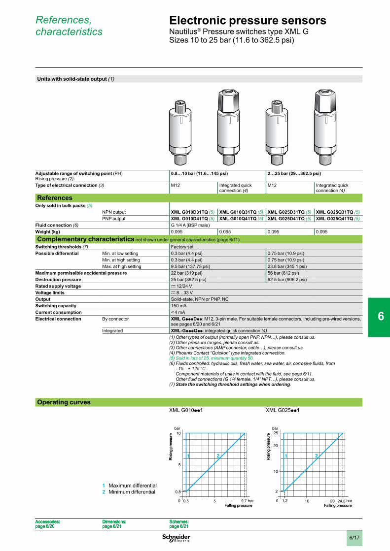
References, characteristics
Units with solid-state output (1)
Adjustable range of switching point (PH) Rising pressure (2) (8)
- 0.08…- 1 bar (- 1.16…- 14.5 psi) 0.08…1 bar (1.16…14.5 psi)
Type of electrical connection (3) M12 Integrated quick connection (4)
M12 Integrated quick connection (4)
ReferencesOnly sold in bulk packs (5)
NPN output XML GM01D31TQ (5) XML GM01Q31TQ (5) XML G001D31TQ (5) XML G001Q31TQ (5)PNP output XML GM01D41TQ (5) XML GM01Q41TQ (5) XML G001D41TQ (5) XML G001Q41TQ (5)
Fluid connection (6) G 1/4 A (BSP male)Weight (kg) 0.095 0.095 0.095 0.095
Complementary characteristics not shown under general characteristics (page 6/11)Switching thresholds (7) Factory setPossible differential Min. at low setting 0.03 bar (0.44 psi) 0.03 bar (0.44 psi)
Min. at high setting 0.03 bar (0.44 psi) 0.03 bar (0.44 psi)Max. at high setting 0.95 bar (13.77 psi) 0.95 bar (13.77 psi)
Maximum permissible accidental pressure 2.7 bar (39.1 psi) 2.7 bar (39.1 psi)Destruction pressure 3 bar (43.5 psi) 3 bar (43.5 psi)Rated supply voltage c 12/24 VVoltage limits c 8…33 VOutput Solid-state, NPN or PNP, NCSwitching capacity 150 mACurrent consumption < 4 mAElectrical connection By connector XML GpppDpp: M12, 3-pin male. For suitable female connectors, including pre-wired versions,
see pages 6/20 and 6/21 Integrated XML GpppQpp: integrated quick connection (4)
(1)Othertypesofoutput(normallyopenPNP,NPN…),pleaseconsultus.(2) Other pressure ranges, please consult us.(3) Other connections (AMP connector, cable…), please consult us.(4) Phoenix Contact “Quickon” type integrated connection.(5) Sold in lots of 25, minimum quantity 50.(6)Fluidscontrolled:hydraulicoils,freshwater,seawater,air,corrosivefluids,
from - 15…+ 125 °C. Componentmaterialsofunitsincontactwiththefluid,seepage6/11. Otherfluidconnections(G1/4female,1/4”NPT…),pleaseconsultus.
(7) State the switching threshold settings when ordering.(8) For vacuum switches (size - 1 bar): adjustable range of switching point (PB) on falling
pressure.
Operating curves
1 Maximum differential2 Minimum differential
XML GM01pp1
XML G001pp1
-1
-0,5
bar
2 1
-0,97bar
0-0,5 -0,05
-0,08
Falli
ng p
ress
ure
Rising pressure
-1
-0,5
bar
2 1
-0,97bar
0-0,5 -0,05
-0,08
Falli
ng p
ress
ure
Rising pressure
1
0,08
0,05 0,97bar
0,5
bar
0 0,5
21
Falling pressure
Ris
ing
pres
sure 1
0,08
0,05 0,97bar
0,5
bar
0 0,5
21
Falling pressure
Ris
ing
pres
sure
Accessories:page 6/20
Dimensions:page 6/21
Schemes:page 6/21
Accessories:page 6/20
Dimensions:page 6/21
Schemes:page 6/21
Accessories:page 6/20
Dimensions:page 6/21
Schemes:page 6/21
Accessories:page 6/20
Dimensions:page 6/21
Schemes:page 6/21
Electronic pressure sensors 0 Nautilus® Pressure and vacuum switches type XML GSizes - 1 to 1 bar (- 14.5 to 14.5 psi)
1
2
3
4
5
6
7
8
9
10
6/17
References, characteristics
Units with solid-state output (1)
Adjustable range of switching point (PH) Rising pressure (2)
0.8…10 bar (11.6…145 psi) 2…25 bar (29…362.5 psi)
Type of electrical connection (3) M12 Integrated quick connection (4)
M12 Integrated quick connection (4)
ReferencesOnly sold in bulk packs (5)
NPN output XML G010D31TQ (5) XML G010Q31TQ (5) XML G025D31TQ (5) XML G025Q31TQ (5)PNP output XML G010D41TQ (5) XML G010Q41TQ (5) XML G025D41TQ (5) XML G025Q41TQ (5)
Fluid connection (6) G 1/4 A (BSP male)Weight (kg) 0.095 0.095 0.095 0.095
Complementary characteristics not shown under general characteristics (page 6/11)Switching thresholds (7) Factory setPossible differential Min. at low setting 0.3 bar (4.4 psi) 0.75 bar (10.9 psi)
Min. at high setting 0.3 bar (4.4 psi) 0.75 bar (10.9 psi)Max. at high setting 9.5 bar (137.75 psi) 23.8 bar (345.1 psi)
Maximum permissible accidental pressure 22 bar (319 psi) 56 bar (812 psi)Destruction pressure 25 bar (362.5 psi) 62.5 bar (906.2 psi)Rated supply voltage c 12/24 VVoltage limits c 8…33 VOutput Solid-state, NPN or PNP, NCSwitching capacity 150 mACurrent consumption < 4 mAElectrical connection By connector XML GpppDpp: M12, 3-pin male. For suitable female connectors, including pre-wired versions,
see pages 6/20 and 6/21Integrated XML-GpppQpp: integrated quick connection (4)
(1)Othertypesofoutput(normallyopenPNP,NPN…),pleaseconsultus.(2) Other pressure ranges, please consult us.(3) Other connections (AMP connector, cable…), please consult us.(4) Phoenix Contact “Quickon” type integrated connection.(5) Sold in lots of 25, minimum quantity 50.(6)Fluidscontrolled:hydraulicoils,freshwater,seawater,air,corrosivefluids,from
- 15…+ 125 °C. Componentmaterialsofunitsincontactwiththefluid,seepage6/11. Otherfluidconnections(G1/4female,1/4”NPT…),pleaseconsultus.
(7) State the switching threshold settings when ordering.
Operating curves
1 Maximum differential2 Minimum differential
XML G010pp1
XML G025pp1
10
0,8
0,5 9,7 bar
5
bar
0 5
21
Falling pressure
Ris
ing
pres
sure 10
0,8
0,5 9,7 bar
5
bar
0 5
21
Falling pressure
Ris
ing
pres
sure 25
2
1,2 24,2 bar
10
bar
0 10
21
20
20Falling pressure
Ris
ing
pres
sure 25
2
1,2 24,2 bar
10
bar
0 10
21
20
20Falling pressure
Ris
ing
pres
sure
Accessories:page 6/20
Dimensions:page 6/21
Schemes:page 6/21
Accessories:page 6/20
Dimensions:page 6/21
Schemes:page 6/21
Accessories:page 6/20
Dimensions:page 6/21
Schemes:page 6/21
Accessories:page 6/20
Dimensions:page 6/21
Schemes:page 6/21
Electronic pressure sensors 0 Nautilus® Pressure switches type XML GSizes 10 to 25 bar (11.6 to 362.5 psi)
1
2
3
4
5
6
7
8
9
10
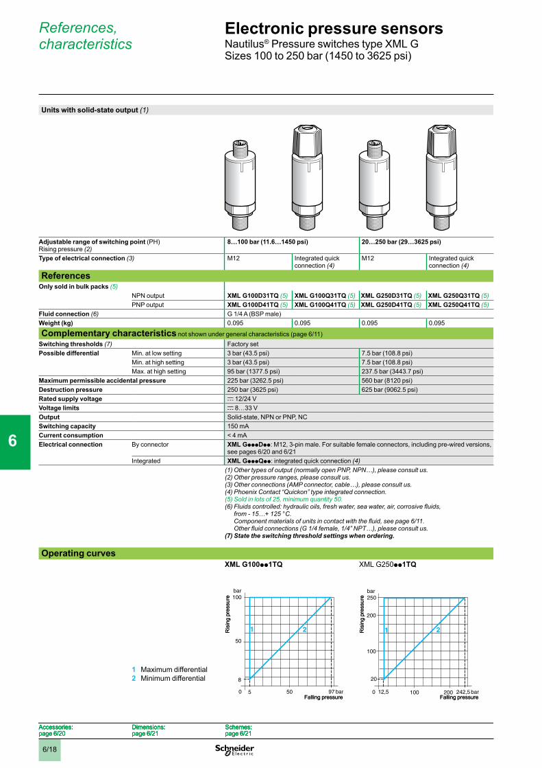
6/18
References, characteristics
Units with solid-state output (1)
Adjustable range of switching point (PH) Rising pressure (2)
8…100 bar (11.6…1450 psi) 20…250 bar (29…3625 psi)
Type of electrical connection (3) M12 Integrated quick connection (4)
M12 Integrated quick connection (4)
ReferencesOnly sold in bulk packs (5)
NPN output XML G100D31TQ (5) XML G100Q31TQ (5) XML G250D31TQ (5) XML G250Q31TQ (5)PNP output XML G100D41TQ (5) XML G100Q41TQ (5) XML G250D41TQ (5) XML G250Q41TQ (5)
Fluid connection (6) G 1/4 A (BSP male)Weight (kg) 0.095 0.095 0.095 0.095
Complementary characteristics not shown under general characteristics (page 6/11)Switching thresholds (7) Factory setPossible differential Min. at low setting 3 bar (43.5 psi) 7.5 bar (108.8 psi)
Min. at high setting 3 bar (43.5 psi) 7.5 bar (108.8 psi)Max. at high setting 95 bar (1377.5 psi) 237.5 bar (3443.7 psi)
Maximum permissible accidental pressure 225 bar (3262.5 psi) 560 bar (8120 psi)Destruction pressure 250 bar (3625 psi) 625 bar (9062.5 psi)Rated supply voltage c 12/24 VVoltage limits c 8…33 VOutput Solid-state, NPN or PNP, NCSwitching capacity 150 mACurrent consumption < 4 mAElectrical connection By connector XML GpppDpp: M12, 3-pin male. For suitable female connectors, including pre-wired versions,
see pages 6/20 and 6/21 Integrated XML GpppQpp: integrated quick connection (4)
(1)Othertypesofoutput(normallyopenPNP,NPN…),pleaseconsultus.(2) Other pressure ranges, please consult us.(3) Other connections (AMP connector, cable…), please consult us.(4) Phoenix Contact “Quickon” type integrated connection.(5) Sold in lots of 25, minimum quantity 50.(6)Fluidscontrolled:hydraulicoils,freshwater,seawater,air,corrosivefluids,
from - 15…+ 125 °C. Componentmaterialsofunitsincontactwiththefluid,seepage6/11. Otherfluidconnections(G1/4female,1/4”NPT…),pleaseconsultus.
(7) State the switching threshold settings when ordering.
Operating curves
1 Maximum differential2 Minimum differential
XML G100pp1TQ
XML G250pp1TQ
100
8
5 97 bar
50
bar
0 50
21
Falling pressure
Ris
ing
pres
sure 100
8
5 97 bar
50
bar
0 50
21
Falling pressure
Ris
ing
pres
sure 250
20
12,5 242,5 bar
100
bar
0 100
21
200
200Falling pressure
Ris
ing
pres
sure 250
20
12,5 242,5 bar
100
bar
0 100
21
200
200Falling pressure
Ris
ing
pres
sure
Accessories:page 6/20
Dimensions:page 6/21
Schemes:page 6/21
Accessories:page 6/20
Dimensions:page 6/21
Schemes:page 6/21
Accessories:page 6/20
Dimensions:page 6/21
Schemes:page 6/21
Accessories:page 6/20
Dimensions:page 6/21
Schemes:page 6/21
Electronic pressure sensors 0 Nautilus® Pressure switches type XML GSizes 100 to 250 bar (1450 to 3625 psi)
1
2
3
4
5
6
7
8
9
10
6/19
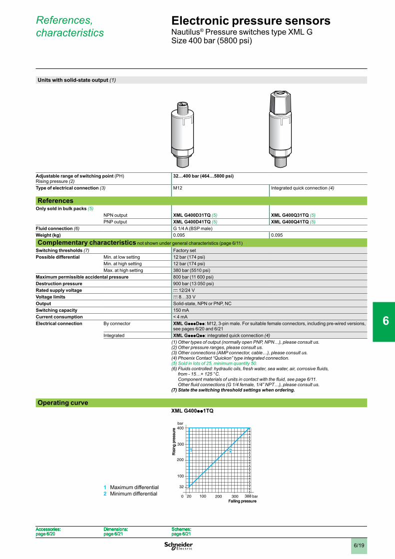
References, characteristics
Units with solid-state output (1)
Adjustable range of switching point (PH) Rising pressure (2)
32…400 bar (464…5800 psi)
Type of electrical connection (3) M12 Integrated quick connection (4)
ReferencesOnly sold in bulk packs (5)
NPN output XML G400D31TQ (5) XML G400Q31TQ (5)PNP output XML G400D41TQ (5) XML G400Q41TQ (5)
Fluid connection (6) G 1/4 A (BSP male)Weight (kg) 0.095 0.095
Complementary characteristics not shown under general characteristics (page 6/11)Switching thresholds (7) Factory setPossible differential Min. at low setting 12 bar (174 psi)
Min. at high setting 12 bar (174 psi)Max. at high setting 380 bar (5510 psi)
Maximum permissible accidental pressure 800 bar (11 600 psi)Destruction pressure 900 bar (13 050 psi)Rated supply voltage c 12/24 VVoltage limits c 8…33 VOutput Solid-state, NPN or PNP, NCSwitching capacity 150 mACurrent consumption < 4 mAElectrical connection By connector XML GpppDpp: M12, 3-pin male. For suitable female connectors, including pre-wired versions,
see pages 6/20 and 6/21 Integrated XML GpppQpp: integrated quick connection (4)
(1)Othertypesofoutput(normallyopenPNP,NPN…),pleaseconsultus.(2) Other pressure ranges, please consult us.(3) Other connections (AMP connector, cable…), please consult us.(4) Phoenix Contact “Quickon” type integrated connection.(5) Sold in lots of 25, minimum quantity 50.(6)Fluidscontrolled:hydraulicoils,freshwater,seawater,air,corrosivefluids,
from - 15…+ 125 °C. Componentmaterialsofunitsincontactwiththefluid,seepage6/11. Otherfluidconnections(G1/4female,1/4”NPT…),pleaseconsultus.
(7) State the switching threshold settings when ordering.
Operating curve
1 Maximum differential2 Minimum differential
XML G400pp1TQ
100
300
100
400
32
20 388 bar
200
200
bar
0
1
300
2
Falling pressure
Ris
ing
pres
sure
100
300
100
400
32
20 388 bar
200
200
bar
0
1
300
2
Falling pressure
Ris
ing
pres
sure
Accessories:page 6/20
Dimensions:page 6/21
Schemes:page 6/21
Accessories:page 6/20
Dimensions:page 6/21
Schemes:page 6/21
Accessories:page 6/20
Dimensions:page 6/21
Schemes:page 6/21
Accessories:page 6/20
Dimensions:page 6/21
Schemes:page 6/21
Electronic pressure sensors 0 Nautilus® Pressure switches type XML GSize 400 bar (5800 psi)
1
2
3
4
5
6
7
8
9
10
6/20
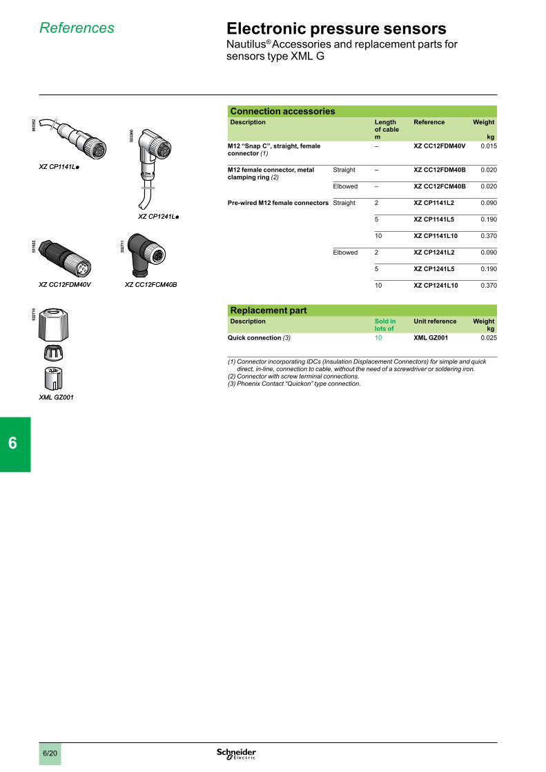
References
Connection accessoriesDescription Length
of cable m
Reference Weight
kgM12 “Snap C”, straight, female connector (1)
– XZ CC12FDM40V 0.015
M12 female connector, metal clamping ring (2)
Straight – XZ CC12FDM40B 0.020
Elbowed – XZ CC12FCM40B 0.020
Pre-wired M12 female connectors Straight 2 XZ CP1141L2 0.090
5 XZ CP1141L5 0.190
10 XZ CP1141L10 0.370
Elbowed 2 XZ CP1241L2 0.090
5 XZ CP1241L5 0.190
10 XZ CP1241L10 0.370
Replacement partDescription Sold in
lots ofUnit reference Weight
kgQuick connection (3) 10 XML GZ001 0.025
(1)ConnectorincorporatingIDCs(InsulationDisplacementConnectors)forsimpleandquickdirect, in-line, connection to cable, without the need of a screwdriver or soldering iron.
(2) Connector with screw terminal connections.(3) Phoenix Contact “Quickon” type connection.
XZ CP1141Lp
XZ CP1241Lp
XZCC12FDM40V
XMLGZ001
5633
52
5033
60
5316
2253
2715
XZ CC12FCM40B
5327
11
XZ CP1141Lp
XZ CP1241Lp
XZCC12FDM40V
XMLGZ001
5633
52
5033
60
5316
2253
2715
XZ CC12FCM40B
5327
11
Electronic pressure sensors 4 Nautilus® Accessories and replacement parts for sensors type XML G
1
2
3
4
5
6
7
8
9
10
6/21
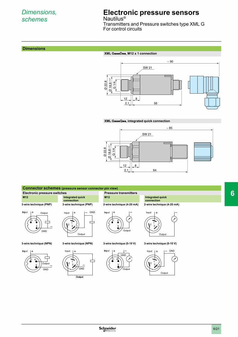
Dimensions, schemes
DimensionsXML GpppDpp, M12 x 1 connection
XML GpppQpp, integrated quick connection
Connector schemes (pressure sensor connector pin view)Electronic pressure switches Pressure transmittersM12 Integrated quick
connectionM12 Integrated quick
connection3-wire technique (PNP) 3-wire technique (PNP) 2-wire technique (4-20 mA) 2-wire technique (4-20 mA)
3-wire technique (NPN) 3-wire technique (NPN) 3-wire technique (0-10 V) 3-wire technique (0-10 V)
2,1
12
Ø 2
2,8
Ø 1
8,8
± 0
,1
G 1
/4
8
56
~ 90
SW 21
2,1
12
Ø 2
2,8
Ø 1
8,8
± 0
,1
G 1
/4
8
56
~ 90
SW 21
2,1
12
Ø 2
2,8
Ø 1
8,8
± 0
,1
G 1
/4
8
64
~ 85
SW 21
2,1
12
Ø 2
2,8
Ø 1
8,8
± 0
,1
G 1
/4
8
64
~ 85
SW 21
4
3
1
+
–
Input Output
GND
4
3
1
+
–
Input Output
GND
+ –
321
GND
Output
Input + –
321
GND
Output
Input
4
3
1
+ –Input
Output
4
3
1
+ –Input
Output
–+
321
Input
Output
–+
321
Input
Output
4
3
1
+
–
Input
Output
GND
4
3
1
+
–
Input
Output
GND
+
–321
GND
Output
Input +
–321
GND
Output
Input
4
3
1
+ –Input
Output
GND
4
3
1
+ –Input
Output
GND–+
321
Input
Output
GND–+
321
Input
Output
GND
Electronic pressure sensors 4 Nautilus®
Transmitters and Pressure switches type XML GFor control circuits
1
2
3
4
5
6
7
8
9
10
6/22
Presentation, principle
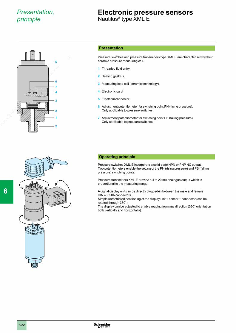
Presentation
Pressure switches and pressure transmitters type XML E are characterised by their ceramic pressure measuring cell.
1 Threaded fluid entry.
2 Sealing gaskets.
3 Measuring load cell (ceramic technology).
4 Electronic card.
5 Electrical connector.
6 Adjustment potentiometer for switching point PH (rising pressure). Only applicable to pressure switches.
7 Adjustment potentiometer for switching point PB (falling pressure). Only applicable to pressure switches.
Operating principle
Pressure switches XML E incorporate a solid-state NPN or PNP NC output.Two potentiometers enable the setting of the PH (rising pressure) and PB (falling pressure) switching points.
Pressure transmitters XML E provide a 4 to 20 mA analogue output which is proportional to the measuring range.
A digital display unit can be directly plugged-in between the male and female DIN 43650A connectors.Simple unrestricted positioning of the display unit + sensor + connector (can be rotated through 360°).The display can be adjusted to enable reading from any direction (360° orientation both vertically and horizontally).
5
1
2
3
4
7
6
2
5
1
2
3
4
7
6
2
30365-2-DESSINS30365-2-DESSINS
Electronic pressure sensors 0 Nautilus® type XML E
1
2
3
4
5
6
7
8
9
10
6/23
Characteristics
Characteristics Conformity to standards e, EN 50081, EN 50082
Product certifications UL, CSA
Protective treatment Standard version “TC”
Ambient air temperature °C For operation: - 15…+ 80
Fluids or products controlled Hydraulic oils, air, fresh water, sea water, corrosive fluids from - 15…+ 80 °C
Component materials in contact with fluid Stainless steel fluid entry type AISI 303, viton gasket
Operating position All positions
Vibration resistance gn 5 (25…200 Hz) and 35 (60…2000 Hz)
Shock resistance gn 50
Electrical protection Protected against reverse polarity, short-circuit and overload
Degree of protection IP 65 conforming to IEC/EN 60529
Operating rate Hz 50
Response time ms < 5
Service life Op. cycles
> 10 million
Drift Of the zero point: < ± 0.03% of the measuring range/°COf the sensitivity: < ± 15% of the measuring range/°C
Precision < ± 0.3% of the measuring range
Fluid connection G 1/4 A (BSP male) conforming to NF E 03-004, ISO 7
Electrical connection DIN 43650A or M12 connector
Electronic pressure sensors 0 Nautilus® type XML E
1
2
3
4
5
6
7
8
9
10

6/24
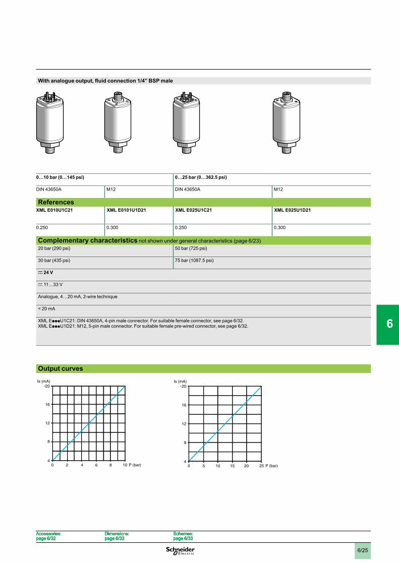
References, characteristics
Type With analogue output, fluid connection 1/4” BSP male
Pressure range 0…- 1 bar (0…- 14.5 psi) 0…1 bar (0…14.5 psi)
Electrical connector type DIN 43650A M12 DIN 43650A M12
ReferencesFluids controlled (2)
Hydraulic oils, fresh water, sea water, air, corrosive fluids, from - 15…+ 80 °C
XML EM01U1C21 XML EM01U1D21 XML E001U1C21 XML E001U1D21
Weight (kg) 0.250 0.300 0.250 0.300
Complementary characteristics not shown under general characteristics (page 6/23)Maximum permissible accidental pressure 1 bar (14.5 psi) 2 bar (29 psi)
Destruction pressure 2 bar (29 psi) 3 bar (43.5 psi)
Rated supply voltage c 24 V
Voltage limits c 11…33 V
Output Analogue, 4…20 mA, 2-wire technique
Current consumption < 20 mA
Electrical connection XML EpppU1C21: DIN 43650A, 4-pin male connector. For suitable female connector, see page 6/32.XML EpppU1D21: M12, 5-pin male connector. For suitable female pre-wired connector, see page 6/32.
(1) Optional digital display for sensor, see page 6/32.(2)Componentmaterialsofunitsincontactwiththefluid,seepage6/23.
Output curves
Other versions Pressure transmitters with 1/4” NPTF fluid connection. Please consult your Regional Sales Office.
Is (mA)
-1 0 P (bar)-0,8 -0,2-0,4-0,6
20
16
12
8
4
Is (mA)
-1 0 P (bar)-0,8 -0,2-0,4-0,6
20
16
12
8
40,2 0,80,60,4
Is (mA)20
16
8
12
40 1 P (bar)0,2 0,80,60,4
Is (mA)20
16
8
12
40 1 P (bar)
Accessories:page 6/32
Dimensions:page 6/33
Schemes:page 6/33
Accessories:page 6/32
Dimensions:page 6/33
Schemes:page 6/33
Accessories:page 6/32
Dimensions:page 6/33
Schemes:page 6/33
Accessories:page 6/32
Dimensions:page 6/33
Schemes:page 6/33
Electronic pressure sensors 0 Nautilus® type XML ETransmitters without display (1)Sizes - 1 to 25 bar (- 14.5 to 362.5 psi)
1
2
3
4
5
6
7
8
9
10
6/25
With analogue output, fluid connection 1/4” BSP male
0…10 bar (0…145 psi) 0…25 bar (0…362.5 psi)
DIN 43650A M12 DIN 43650A M12
ReferencesXML E010U1C21
XML E0101U1D21 XML E025U1C21 XML E025U1D21
0.250 0.300 0.250 0.300
Complementary characteristics not shown under general characteristics (page 6/23)20 bar (290 psi) 50 bar (725 psi)
30 bar (435 psi) 75 bar (1087.5 psi)
c 24 V
c 11…33 V
Analogue, 4…20 mA, 2-wire technique
< 20 mA
XML EpppU1C21: DIN 43650A, 4-pin male connector. For suitable female connector, see page 6/32.XML EpppU1D21: M12, 5-pin male connector. For suitable female pre-wired connector, see page 6/32.
Output curves
2 864
Is (mA)20
16
8
12
40 10 P (bar)2 864
Is (mA)20
16
8
12
40 10 P (bar) 5 201510
Is (mA)20
16
8
12
40 25 P (bar)5 201510
Is (mA)20
16
8
12
40 25 P (bar)
Accessories:page 6/32
Dimensions:page 6/33
Schemes:page 6/33
Accessories:page 6/32
Dimensions:page 6/33
Schemes:page 6/33
Accessories:page 6/32
Dimensions:page 6/33
Schemes:page 6/33
Accessories:page 6/32
Dimensions:page 6/33
Schemes:page 6/33
0
1
2
3
4
5
6
7
8
9
10
6/26
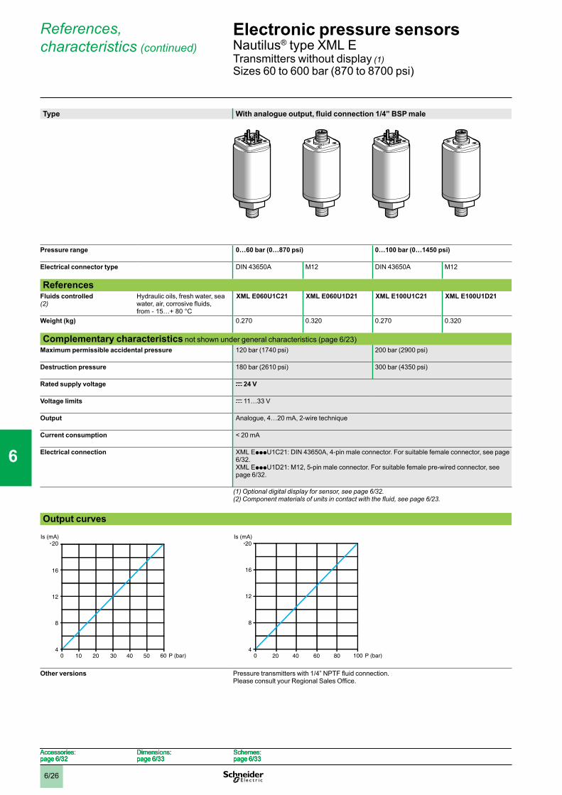
References, characteristics (continued)
Type With analogue output, fluid connection 1/4” BSP male
Pressure range 0…60 bar (0…870 psi) 0…100 bar (0…1450 psi)
Electrical connector type DIN 43650A M12 DIN 43650A M12
ReferencesFluids controlled (2)
Hydraulic oils, fresh water, sea water, air, corrosive fluids, from - 15…+ 80 °C
XML E060U1C21 XML E060U1D21 XML E100U1C21 XML E100U1D21
Weight (kg) 0.270 0.320 0.270 0.320
Complementary characteristics not shown under general characteristics (page 6/23)Maximum permissible accidental pressure 120 bar (1740 psi) 200 bar (2900 psi)
Destruction pressure 180 bar (2610 psi) 300 bar (4350 psi)
Rated supply voltage c 24 V
Voltage limits c 11…33 V
Output Analogue, 4…20 mA, 2-wire technique
Current consumption < 20 mA
Electrical connection XML EpppU1C21: DIN 43650A, 4-pin male connector. For suitable female connector, see page 6/32.XML EpppU1D21: M12, 5-pin male connector. For suitable female pre-wired connector, see page 6/32.
(1) Optional digital display for sensor, see page 6/32.(2)Componentmaterialsofunitsincontactwiththefluid,seepage6/23.
Output curves
Other versions Pressure transmitters with 1/4” NPTF fluid connection. Please consult your Regional Sales Office.
10 4030 5020
Is (mA)20
16
8
12
40 60 P (bar)10 4030 5020
Is (mA)20
16
8
12
40 60 P (bar) 20 806040
Is (mA)20
16
8
12
40 100 P (bar)20 806040
Is (mA)20
16
8
12
40 100 P (bar)
Accessories:page 6/32
Dimensions:page 6/33
Schemes:page 6/33
Accessories:page 6/32
Dimensions:page 6/33
Schemes:page 6/33
Accessories:page 6/32
Dimensions:page 6/33
Schemes:page 6/33
Accessories:page 6/32
Dimensions:page 6/33
Schemes:page 6/33
Electronic pressure sensors 0 Nautilus® type XML ETransmitters without display (1)Sizes 60 to 600 bar (870 to 8700 psi)
1
2
3
4
5
6
7
8
9
10
6/27
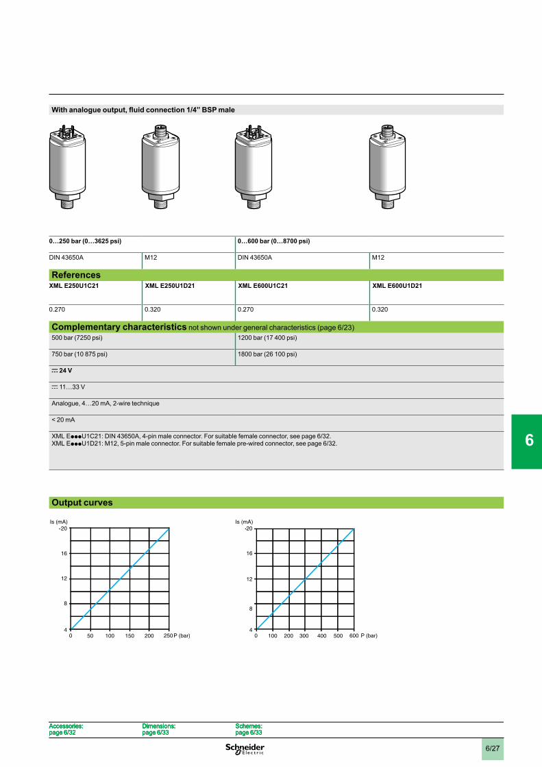
With analogue output, fluid connection 1/4” BSP male
0…250 bar (0…3625 psi) 0…600 bar (0…8700 psi)
DIN 43650A M12 DIN 43650A M12
ReferencesXML E250U1C21
XML E250U1D21 XML E600U1C21 XML E600U1D21
0.270 0.320 0.270 0.320
Complementary characteristics not shown under general characteristics (page 6/23)500 bar (7250 psi) 1200 bar (17 400 psi)
750 bar (10 875 psi) 1800 bar (26 100 psi)
c 24 V
c 11…33 V
Analogue, 4…20 mA, 2-wire technique
< 20 mA
XML EpppU1C21: DIN 43650A, 4-pin male connector. For suitable female connector, see page 6/32.XML EpppU1D21: M12, 5-pin male connector. For suitable female pre-wired connector, see page 6/32.
Output curves
50 200150100
Is (mA)20
16
8
12
40 250P (bar)50 200150100
Is (mA)20
16
8
12
40 250P (bar) 100 400300 500200
Is (mA)20
16
8
12
40 600 P (bar)100 400300 500200
Is (mA)20
16
8
12
40 600 P (bar)
Accessories:page 6/32
Dimensions:page 6/33
Schemes:page 6/33
Accessories:page 6/32
Dimensions:page 6/33
Schemes:page 6/33
Accessories:page 6/32
Dimensions:page 6/33
Schemes:page 6/33
Accessories:page 6/32
Dimensions:page 6/33
Schemes:page 6/33
0
1
2
3
4
5
6
7
8
9
10

6/28
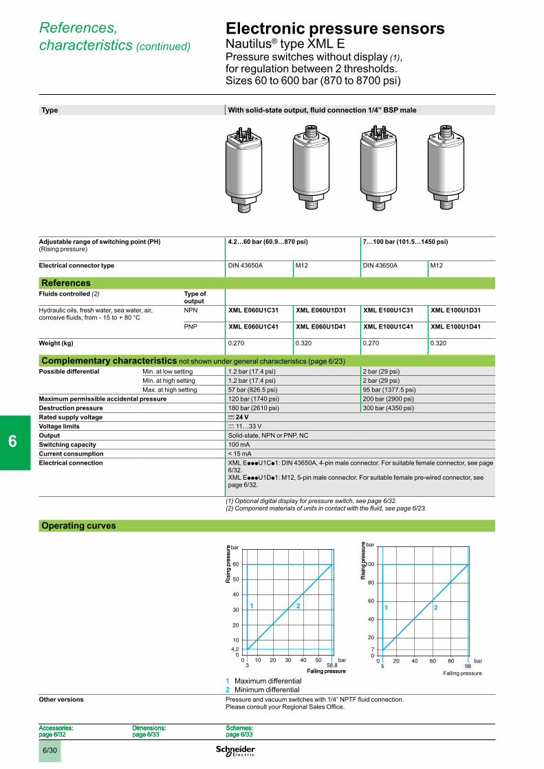
References, characteristics
Type With solid-state output, fluid connection 1/4” BSP male
Adjustable range of switching point (PH)(Rising pressure) (2)
- 0.07…- 1 bar (- 1.015…- 14.5 psi) 0.07…1 bar (1.015…14.5 psi)
Electrical connector type DIN 43650A M12 DIN 43650A M12
ReferencesFluids controlled (3) Type of
outputHydraulic oils, fresh water, sea water, air, corrosive fluids, from - 15 to + 80 °C
NPN XML EM01U1C31 XML EM01U1D31 XML E001U1C31 XML E001U1D31
PNP XML EM01U1C41 XML EM01U1D41 XML E001U1C41 XML E001U1D41
Weight (kg) 0.250 0.300 0.250 0.300
Complementary characteristics not shown under general characteristics (page 6/23)Possible differential Min. at low setting 0.02 bar (0.29 psi) 0.02 bar (0.29 psi)
Min. at high setting 0.02 bar (0.29 psi) 0.02 bar (0.29 psi)Max. at high setting 0.95 bar (13.77 psi) (max. differential at low
setting)0.95 bar (13.77 psi)
Maximum permissible accidental pressure 1 bar (14.5 psi) 2 bar (29 psi)Destruction pressure 2 bar (29 psi) 3 bar (43.5 psi)Rated supply voltage c 24 VVoltage limits c 11…33 VOutput Solid-state, NPN or PNP, NCSwitching capacity 100 mACurrent consumption < 15 mAElectrical connection XML EpppU1Cp1: DIN 43650A, 4-pin male connector. For suitable female connector, see page
6/32.XML EpppU1Dp1: M12, 4-pin male connector. For suitable female pre-wired connector, see page 6/32.
(1) Optional digital display for pressure switch, see page 6/32.(2) For vacuum switches (size -1 bar): adjustable range of switching point (PB) on falling
pressure.(3)Componentmaterialsofunitsincontactwiththefluid,seepage6/23.
Operating curves
1 Maximum differential2 Minimum differential
Other versions Pressure and vacuum switches with 1/4” NPTF fluid connection. Please consult your Regional Sales Office.
0bar
bar0 -0,2-0,05
-0,4 -0,6 -0,8-0,98
-0,2
-0,07
-0,4
-0,6
-0,8
-1
1 2
Falli
ng p
ress
ure
Rising pressure
0bar
bar0 -0,2-0,05
-0,4 -0,6 -0,8-0,98
-0,2
-0,07
-0,4
-0,6
-0,8
-1
1 2
Falli
ng p
ress
ure
Rising pressure
bar
bar0 0,20,05
0,4 0,6 0,80,98
0,07
1
1 2
0,8
0,6
0,4
0,2
0
Falli
ng p
ress
ure
Rising pressure
bar
bar0 0,20,05
0,4 0,6 0,80,98
0,07
1
1 2
0,8
0,6
0,4
0,2
0
Falli
ng p
ress
ure
Rising pressure
Accessories:page 6/32
Dimensions:page 6/33
Schemes:page 6/33
Accessories:page 6/32
Dimensions:page 6/33
Schemes:page 6/33
Accessories:page 6/32
Dimensions:page 6/33
Schemes:page 6/33
Accessories:page 6/32
Dimensions:page 6/33
Schemes:page 6/33
Electronic pressure sensors 0 Nautilus® type XML EVacuum and pressure switches without display (1),for regulation between 2 thresholdsSizes - 1 to 25 bar (- 14.5 to 362.5 psi)
1
2
3
4
5
6
7
8
9
10
6/29
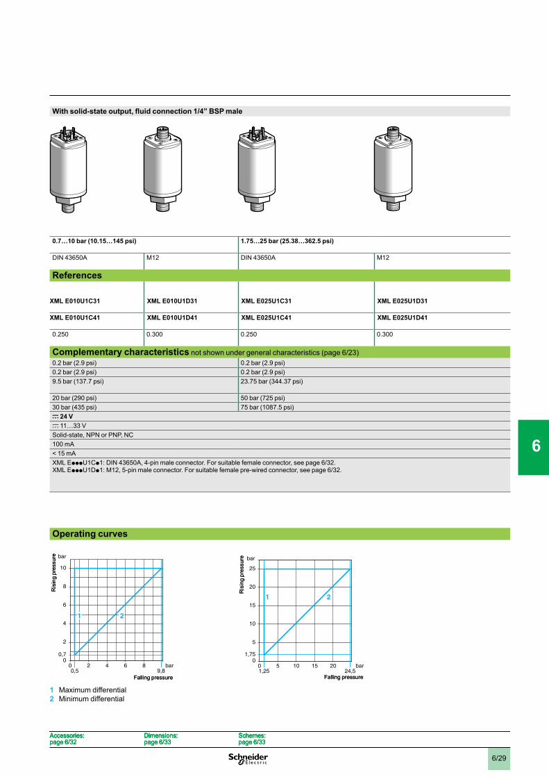
With solid-state output, fluid connection 1/4” BSP male
0.7…10 bar (10.15…145 psi) 1.75…25 bar (25.38…362.5 psi)
DIN 43650A M12 DIN 43650A M12
References XML E010U1C31
XML E010U1D31
XML E025U1C31
XML E025U1D31
XML E010U1C41 XML E010U1D41 XML E025U1C41 XML E025U1D41
0.250 0.300 0.250 0.300
Complementary characteristics not shown under general characteristics (page 6/23)0.2 bar (2.9 psi) 0.2 bar (2.9 psi)0.2 bar (2.9 psi) 0.2 bar (2.9 psi)9.5 bar (137.7 psi) 23.75 bar (344.37 psi)
20 bar (290 psi) 50 bar (725 psi)30 bar (435 psi) 75 bar (1087.5 psi)c 24 Vc 11…33 VSolid-state, NPN or PNP, NC100 mA< 15 mAXML EpppU1Cp1: DIN 43650A, 4-pin male connector. For suitable female connector, see page 6/32.XML EpppU1Dp1: M12, 5-pin male connector. For suitable female pre-wired connector, see page 6/32.
Operating curves
1 Maximum differential2 Minimum differential
bar
bar0 20,5
4 6 89,8
0,7
10
8
6
4
2
0
21
Ris
ing
pres
sure
Falling pressure
bar
bar0 20,5
4 6 89,8
0,7
10
8
6
4
2
0
21
Ris
ing
pres
sure
Falling pressure
bar
bar0 51,25
10 15 2024,5
1,75
5
25
10
15
20
0
21
Ris
ing
pres
sure
Falling pressure
bar
bar0 51,25
10 15 2024,5
1,75
5
25
10
15
20
0
21
Ris
ing
pres
sure
Falling pressure
Accessories:page 6/32
Dimensions:page 6/33
Schemes:page 6/33
Accessories:page 6/32
Dimensions:page 6/33
Schemes:page 6/33
Accessories:page 6/32
Dimensions:page 6/33
Schemes:page 6/33
Accessories:page 6/32
Dimensions:page 6/33
Schemes:page 6/33
0
1
2
3
4
5
6
7
8
9
10
6/30
Falling pressure
References, characteristics (continued)
Type With solid-state output, fluid connection 1/4” BSP male
Adjustable range of switching point (PH)(Rising pressure)
4.2…60 bar (60.9…870 psi) 7…100 bar (101.5…1450 psi)
Electrical connector type DIN 43650A M12 DIN 43650A M12
ReferencesFluids controlled (2) Type of
outputHydraulic oils, fresh water, sea water, air, corrosive fluids, from - 15 to + 80 °C
NPN XML E060U1C31 XML E060U1D31 XML E100U1C31 XML E100U1D31
PNP XML E060U1C41 XML E060U1D41 XML E100U1C41 XML E100U1D41
Weight (kg) 0.270 0.320 0.270 0.320
Complementary characteristics not shown under general characteristics (page 6/23)Possible differential Min. at low setting 1.2 bar (17.4 psi) 2 bar (29 psi)
Min. at high setting 1.2 bar (17.4 psi) 2 bar (29 psi)Max. at high setting 57 bar (826.5 psi) 95 bar (1377.5 psi)
Maximum permissible accidental pressure 120 bar (1740 psi) 200 bar (2900 psi)Destruction pressure 180 bar (2610 psi) 300 bar (4350 psi)Rated supply voltage c 24 VVoltage limits c 11…33 VOutput Solid-state, NPN or PNP, NCSwitching capacity 100 mACurrent consumption < 15 mAElectrical connection XML EpppU1Cp1: DIN 43650A, 4-pin male connector. For suitable female connector, see page
6/32.XML EpppU1Dp1: M12, 5-pin male connector. For suitable female pre-wired connector, see page 6/32.
(1) Optional digital display for pressure switch, see page 6/32.(2)Componentmaterialsofunitsincontactwiththefluid,seepage6/23.
Operating curves
1 Maximum differential2 Minimum differential
Other versions Pressure and vacuum switches with 1/4” NPTF fluid connection. Please consult your Regional Sales Office.
bar
bar0 50403020103 58,8
4,2
10
20
30
40
50
60
0
1 2
Ris
ing
pres
sure
Falling pressure
bar
bar0 50403020103 58,8
4,2
10
20
30
40
50
60
0
1 2
Ris
ing
pres
sure
Falling pressure
bar
bar0 205
40 60 8098
7
20
100
40
60
80
0
1 2
Ris
ing
pres
sure bar
bar0 205
40 60 8098
7
20
100
40
60
80
0
1 2
Ris
ing
pres
sure
Accessories:page 6/32
Dimensions:page 6/33
Schemes:page 6/33
Accessories:page 6/32
Dimensions:page 6/33
Schemes:page 6/33
Accessories:page 6/32
Dimensions:page 6/33
Schemes:page 6/33
Accessories:page 6/32
Dimensions:page 6/33
Schemes:page 6/33
Electronic pressure sensors 0 Nautilus® type XML EPressure switches without display (1), for regulation between 2 thresholds. Sizes 60 to 600 bar (870 to 8700 psi)
1
2
3
4
5
6
7
8
9
10

6/31
With solid-state output, fluid connection 1/4” BSP male
17.5…250 bar (253.7…3625 psi) 42…600 bar (609…8700 psi)
DIN 43650A M12 DIN 43650A M12
References
XML E250U1C31 XML E250U1D31 XML E600U1C31 XML E600U1D31
XML E250U1C41 XML E250U1D41 XML E600U1C41 XML E600U1D41
0.270 0.320 0.270 0.320
Complementary characteristics not shown under general characteristics (page 6/23)5 bar (72.5 psi) 12 bar (174 psi)5 bar (72.5 psi) 12 bar (174 psi)237.5 bar (3443.7 psi) 570 bar (8265 psi)500 bar (7250 psi) 1200 bar (17 400 psi)750 bar (10 875 psi) 1800 bar (26 100 psi)c 24 Vc 11…33 VSolid-state, NPN or PNP, NC100 mA< 15 mAXML EpppU1Cp1: DIN 43650A, 4-pin male connector. For suitable female connector, see page 6/32.XML EpppU1Dp1: M12, 5-pin male connector. For suitable female pre-wired connector, see page 6/32.
Operating curves
1 Maximum differential2 Minimum differential
bar
17,5
50
250
100
150
200
0
1 2
bar0 5012,5
100 150 200245
Ris
ing
pres
sure
Falling pressure
bar
17,5
50
250
100
150
200
0
1 2
bar0 5012,5
100 150 200245
Ris
ing
pres
sure
Falling pressure
bar
bar0 50040030020010030 588
42
100
200
300
400
500
600
0
1 2
Ris
ing
pres
sure
Falling pressure
bar
bar0 50040030020010030 588
42
100
200
300
400
500
600
0
1 2
Ris
ing
pres
sure
Falling pressure
Accessories:page 6/32
Dimensions:page 6/33
Schemes:page 6/33
Accessories:page 6/32
Dimensions:page 6/33
Schemes:page 6/33
Accessories:page 6/32
Dimensions:page 6/33
Schemes:page 6/33
Accessories:page 6/32
Dimensions:page 6/33
Schemes:page 6/33
0
1
2
3
4
5
6
7
8
9
10

6/32
References
AccessoriesDescription Sensor
sizeReference Weight
bar kgDigital displays for analogue pressure sensors
- 1…0 XML EZM01 0.100
0…1 XML EZ001 0.100
0…10 XML EZ010 0.100
0…25 XML EZ025 0.100
0…60 XML EZ060 0.100
0…100 XML EZ100 0.100
0…250 XML EZ250 0.100
0…600 XML EZ600 0.100
Connection accessoriesDescription Length
of cable Reference Weight
m kgFemale DIN 43650 A connector – XZ CC43FCP40B 0.035
DIN 43650 A - straight M12 male jumper cables for splitter boxes
1 m XZ CR1523062K1 0.080
2 m XZ CR1523062K2 0.110
Pre-wired M12, straight, female connectors
2 m XZ CP1164L2 0.115
5 m XZ CP1164L5 0.270
10 m XZ CP1164L10 0.520
Pre-wired M12, elbowed, female connectors
2 m XZ CP1264L2 0.115
5 m XZ CP1264L5 0.270
10 m XZ CP1264L10 0.520
XML EZppppXML EZpppp
XZ CC43FCP40BXZ CC43FCP40B
XZ CP1164LpXZ CP1164Lp
XZ CP1264LpXZ CP1264Lp
Electronic pressure sensors 0 Nautilus® type XML EAccessories
1
2
3
4
5
6
7
8
9
10
6/33
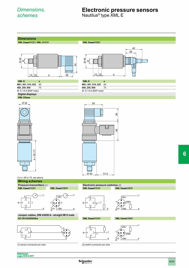
Dimensions, schemes
DimensionsXML EpppU1C21, XML U1C31 XML EpppU1D31
XML E a XML E aM01, 001, 010, 025 65 M01, 001, 010, 025 65060, 250, 600 75 060, 250, 600 75Ø: G 1/4 A (BSP male) Ø: G 1/4 A (BSP male)Digital displaysXML EZppp
(1) a = 65 or 75, see above.
Wiring schemesPressure transmitters (1) Electronic pressure switches (2)XML EpppU1C21 XML EpppU1D21 XML EpppU1C31 XML EpppU1D31
Jumper cables, DIN 43650 A - straight M12 maleXZ CR15230D62Kp XML EpppU1C41 XML EpppU1D41
(1) sensor connector pin view (2) switch connector pin view
12
ØØ 4
0
5010 a 3612
ØØ 4
0
5010 a 36
4226
12
ØØ 4
0
10 a
4226
12
ØØ 4
0
10 a
a +
22 (
1)a
+ 22
(1)
Ø 40
50
36
66
51,5Ø 40
50
36
66
51,5
3
2
1
–
+
3
2
1
–
+
4 2
1/BN
3/BU–
+YG
4 2
1/BN
3/BU–
+YG
3
2
1
–
+
3
2
1
–
+
2/WH4
1/BN
3/BU–
+YG
2/WH4
1/BN
3/BU–
+YG
3
1
4
1
524 3
1
4
1
524
3
2
1
–
+
3
2
1
–
+
2/WH4
1/BN
3/BU–
+YG
2/WH4
1/BN
3/BU–
+YG
References: pages 6/24 to 6/31References: pages 6/24 to 6/31References: pages 6/24 to 6/31References: pages 6/24 to 6/31
Electronic pressure sensors 0 Nautilus® type XML E
1
2
3
4
5
6
7
8
9
10
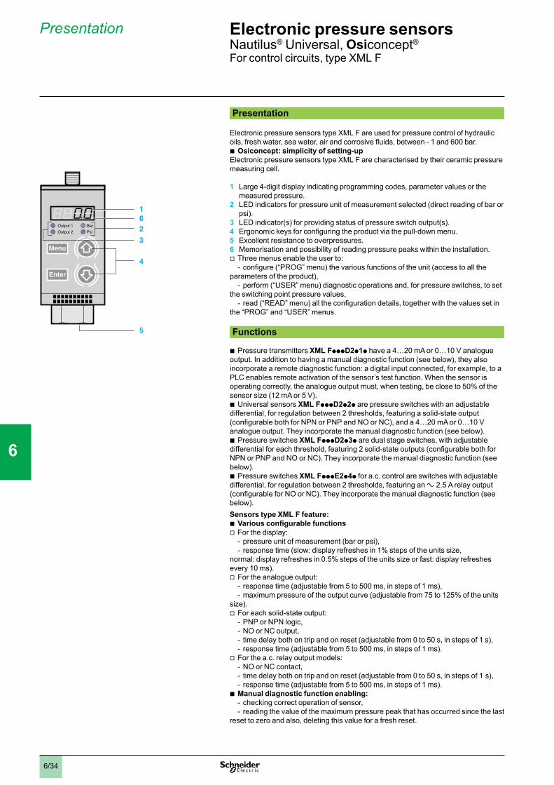
6/34
Presentation
Presentation
Electronic pressure sensors type XML F are used for pressure control of hydraulic oils, fresh water, sea water, air and corrosive fluids, between - 1 and 600 bar.
Osiconcept: simplicity of setting-upElectronic pressure sensors type XML F are characterised by their ceramic pressure measuring cell.
1 Large 4-digit display indicating programming codes, parameter values or the measured pressure.
2 LED indicators for pressure unit of measurement selected (direct reading of bar or psi).
3 LED indicator(s) for providing status of pressure switch output(s).4 Ergonomic keys for configuring the product via the pull-down menu.5 Excellent resistance to overpressures.6 Memorisation and possibility of reading pressure peaks within the installation.
Three menus enable the user to:configure (“PROG” menu) the various functions of the unit (access to all the
parameters of the product), perform (“USER” menu) diagnostic operations and, for pressure switches, to set
the switching point pressure values,read (“READ” menu) all the configuration details, together with the values set in
the “PROG” and “USER” menus.
Functions
Pressure transmitters XML FpppD2p1p have a 4…20 mA or 0…10 V analogue output. In addition to having a manual diagnostic function (see below), they also incorporate a remote diagnostic function: a digital input connected, for example, to a PLC enables remote activation of the sensor’s test function. When the sensor is operating correctly, the analogue output must, when testing, be close to 50% of the sensor size (12 mA or 5 V).
Universal sensors XML FpppD2p2p are pressure switches with an adjustable differential, for regulation between 2 thresholds, featuring a solid-state output (configurable both for NPN or PNP and NO or NC), and a 4…20 mA or 0…10 V analogue output. They incorporate the manual diagnostic function (see below).
Pressure switches XML FpppD2p3p are dual stage switches, with adjustable differential for each threshold, featuring 2 solid-state outputs (configurable both for NPN or PNP and NO or NC). They incorporate the manual diagnostic function (see below).
Pressure switches XML FpppE2p4p for a.c. control are switches with adjustable differential, for regulation between 2 thresholds, featuring an a 2.5 A relay output (configurable for NO or NC). They incorporate the manual diagnostic function (see below).Sensors type XML F feature:
Various configurable functionsFor the display:
pressure unit of measurement (bar or psi),response time (slow: display refreshes in 1% steps of the units size,
normal: display refreshes in 0.5% steps of the units size or fast: display refreshes every 10 ms).
For the analogue output:response time (adjustable from 5 to 500 ms, in steps of 1 ms),maximum pressure of the output curve (adjustable from 75 to 125% of the units
size).For each solid-state output:
PNP or NPN logic,NO or NC output,time delay both on trip and on reset (adjustable from 0 to 50 s, in steps of 1 s),response time (adjustable from 5 to 500 ms, in steps of 1 ms).
For the a.c. relay output models:NO or NC contact,time delay both on trip and on reset (adjustable from 0 to 50 s, in steps of 1 s),response time (adjustable from 5 to 500 ms, in steps of 1 ms).
Manual diagnostic function enabling:checking correct operation of sensor,reading the value of the maximum pressure peak that has occurred since the last
reset to zero and also, deleting this value for a fresh reset.
b
v-
-
-
b
b
b
b
bv
--
v--
v----
v---
b--
Enter
Menu
Bar
Psi
Output 1
Output 2
16
5
4
2
3
Enter
Menu
Bar
Psi
Output 1
Output 2
16
5
4
2
3
Electronic pressure sensors 0 Nautilus® Universal, Osiconcept®
For control circuits, type XML F
1
2
3
4
5
6
7
8
9
10
6/35
Characteristics
Environmental characteristicsConformity to standards e,
IEC/EN 60947-1, IEC/EN 60947-5-1, EN 50081, EN 50082, EN 61000-6-2, EN 61000-4-2/3/4/5/6/8/11
Product certifications UL, CSAProtective treatment Standard version “TC”
Ambient air temperature For operation - 25…+ 80 °C (d.c. models)- 25…+ 75 °C (a.c. models)
Fluids or products controlled Hydraulic oils, air, fresh water, sea water, corrosive fluids from - 15…+ 80 °CComponent materials in contact with fluid Stainless steel fluid entry type AISI 303, viton gasket
Operating position All positionsVibration resistance 5 gn (25…200 Hz) and 35 gn (60…2000 Hz), conforming to IEC 68-2-6
Shock resistance 50 gn, conforming to IEC 68-2-27Electrical protection Protected against reverse polarity, short-circuit, overload and connection faults
Resistance to electromagnetic interference
Electrostatic discharges Standard EN 61000-4-2 contact 4kV, air 8 kVRadiated electromagnetic fields
Standard EN 61000-4-3 10 V/m
Fast transients Standard EN 61000-4-4 2 kVSurges Standard EN 61000-4-5 (AC) 1 kV, (DC) 0.5 kVConducted disturbances, induced by radio frequency fields
Standard EN 61000-4-6 10 V
Degree of protection IP 67 conforming to IEC/EN 60529, NEMA 4/6/12/13
Operating rate < 50 HzOutput response time Adjustable from 5 to 500 ms, in steps of 1 ms
Service life In millions of operating cycles
> 10
Drift Of the zero point < ± 0.1% of the measuring range/°C
Of the sensitivity < ± 0.03% of the measuring range/°C
Precision Analogue output y 0.6% of the measuring range, output offset < 200 mVDigital output y 0.6% of the measuring range
Repeat accuracy y 0.5% of the measuring rangeDisplay response time Adjustable; 3 options:
slow (1% of the units size), normal (0.5% of the units size), or fast (refreshed every 10 ms)
---
Fluid connection G 1/4 A (BSP female) conforming to NF E 03-004 and ISO 7, 1/4” NPT or SAE 7/16-20UNF female, depending on model
Electrical connection M12 “Snap-C” compatible connector or SAE 7/8-16UN connector, depending on model
Electronic pressure sensors 0 Nautilus® Universal, Osiconcept®
For control circuits, type XML F
1
2
3
4
5
6
7
8
9
10
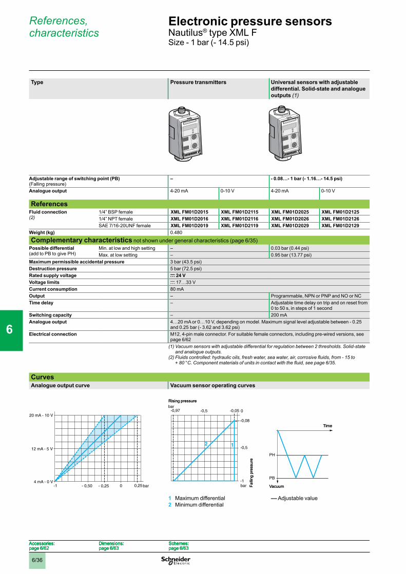
6/36
References, characteristics
Type Pressure transmitters Universal sensors with adjustable differential. Solid-state and analogue outputs (1)
Adjustable range of switching point (PB) (Falling pressure)
– - 0.08…- 1 bar (- 1.16…- 14.5 psi)
Analogue output 4-20 mA 0-10 V 4-20 mA 0-10 V
ReferencesFluid connection (2)
1/4” BSP female XML FM01D2015 XML FM01D2115 XML FM01D2025 XML FM01D21251/4” NPT female XML FM01D2016 XML FM01D2116 XML FM01D2026 XML FM01D2126SAE 7/16-20UNF female XML FM01D2019 XML FM01D2119 XML FM01D2029 XML FM01D2129
Weight (kg) 0.480
Complementary characteristics not shown under general characteristics (page 6/35)Possible differential (add to PB to give PH)
Min. at low and high setting – 0.03 bar (0.44 psi)Max. at low setting – 0.95 bar (13.77 psi)
Maximum permissible accidental pressure 3 bar (43.5 psi)Destruction pressure 5 bar (72.5 psi)Rated supply voltage c 24 VVoltage limits c 17…33 VCurrent consumption 80 mAOutput – Programmable, NPN or PNP and NO or NCTime delay – Adjustable time delay on trip and on reset from
0 to 50 s, in steps of 1 secondSwitching capacity – 200 mAAnalogue output 4…20 mA or 0…10 V, depending on model. Maximum signal level adjustable between - 0.25
and 0.25 bar (- 3.62 and 3.62 psi)Electrical connection M12, 4-pin male connector. For suitable female connectors, including pre-wired versions, see
page 6/62(1)Vacuumsensorswithadjustabledifferentialforregulationbetween2thresholds.Solid-state
and analogue outputs.(2)Fluidscontrolled:hydraulicoils,freshwater,seawater,air,corrosivefluids,from-15to
+80°C.Componentmaterialsofunitsincontactwiththefluid,seepage6/35.
CurvesAnalogue output curve Vacuum sensor operating curves
1 Maximum differential2 Minimum differential
–– Adjustable value
- 0,25 bar4 mA - 0 V
- 0,50 0,250
20 mA - 10 V
12 mA - 5 V
-1 - 0,25 bar4 mA - 0 V
- 0,50 0,250
20 mA - 10 V
12 mA - 5 V
-1-1
-0,5
bar
2 1
-0,97bar
0-0,5 -0,05
-0,08
Rising pressure
Falli
ng p
ress
ure
-1
-0,5
bar
2 1
-0,97bar
0-0,5 -0,05
-0,08
Rising pressure
Falli
ng p
ress
ure
PH
PB
Vacuum
Time
PH
PB
Vacuum
Time
Accessories:page 6/62
Dimensions:page 6/63
Schemes:page 6/63
Accessories:page 6/62
Dimensions:page 6/63
Schemes:page 6/63
Accessories:page 6/62
Dimensions:page 6/63
Schemes:page 6/63
Accessories:page 6/62
Dimensions:page 6/63
Schemes:page 6/63
Electronic pressure sensors 0 Nautilus® type XML FSize - 1 bar (- 14.5 psi)
1
2
3
4
5
6
7
8
9
10

6/37
References, characteristics (continued)
Type Vacuum switches with adjustable differential and relay output (1)
Dual stage adjustable vacuum switches with solid-state outputs (2)
Adjustable range of switching point(s) (PB or PB1 and PB2) (Falling pressure)
- 0.08…- 1 bar (- 1.16…- 14.5 psi)
ReferencesFluid connection (3)
1/4” BSP female XML FM01E2045 XML FM01D20351/4” NPT female XML FM01E2046 XML FM01D2036SAE 7/16-20UNF female XML FM01E2049 XML FM01D2039
Weight (kg) 0.590 0.480
Complementary characteristics not shown under general characteristics (page 6/35)Possible differential (add to:- PB to give PH- PB1 & PB2 to give PH1 & PH2)
Min. at low and high setting 0.03 bar (0.44 psi) For each stage: min. at low and high setting: 0.03 bar (0.44 psi)max. at low setting: 0.95 bar (13.77 psi)
Max. at low setting 0.95 bar (13.77 psi)
Maximum permissible accidental pressure 3 bar (43.5 psi)Destruction pressure 5 bar (72.5 psi)Rated supply voltage a 120 V c 24 VVoltage limits a 102…132 V c 17…33 VCurrent consumption 32 mA 80 mAOutput Relay Programmable, NPN or PNP and NO or NCTime delay Adjustable time delay on trip and on reset from 0 to 50 s, in steps of 1 secondSwitching capacity 2.5 A, AC-15, C300 (120 V - 1.5 A) 200 mAElectrical connection SAE 7/8-16UN, 5-pin male connector. For
suitable female pre-wired connectors, see page 6/62.
M12, 4-pin male connector. For suitable female connectors, including pre-wired versions, see page 6/62
(1)Vacuumswitcheswithadjustabledifferentialforregulationbetween2thresholds.Relayoutput.
(2)Vacuumswitcheswith2adjustablestagesandadjustabledifferentialforeachthreshold.Solid-state outputs.
(3)Fluidscontrolled:hydraulicoils,freshwater,seawater,air,corrosivefluids,from-15to +80°C.Componentmaterialsofunitsincontactwiththefluid,seepage6/35.
Vacuum switch operating curves(Curve for each stage for dual stage vacuum switches) Vacuum switches with relay output Dual stage vacuum switches
1 Maximum differential2 Minimum differential
–– Adjustable value –– Adjustable value
-1
-0,5
bar
2 1
-0,97bar
0-0,5 -0,05
-0,08
Falli
ng p
ress
ure
Rising pressure
-1
-0,5
bar
2 1
-0,97bar
0-0,5 -0,05
-0,08
Falli
ng p
ress
ure
Rising pressure
PH
PB
Vacuum
Time
PH
PB
Vacuum
Time
PH1
PH2
PB2
PB1
Time
Vacuum
PH1
PH2
PB2
PB1
Time
Vacuum
Accessories:page 6/62
Dimensions:page 6/63
Schemes:page 6/63
Accessories:page 6/62
Dimensions:page 6/63
Schemes:page 6/63
Accessories:page 6/62
Dimensions:page 6/63
Schemes:page 6/63
Accessories:page 6/62
Dimensions:page 6/63
Schemes:page 6/63
Electronic pressure sensors 0 Nautilus® type XML FSize - 1 bar (- 14.5 psi)
1
2
3
4
5
6
7
8
9
10
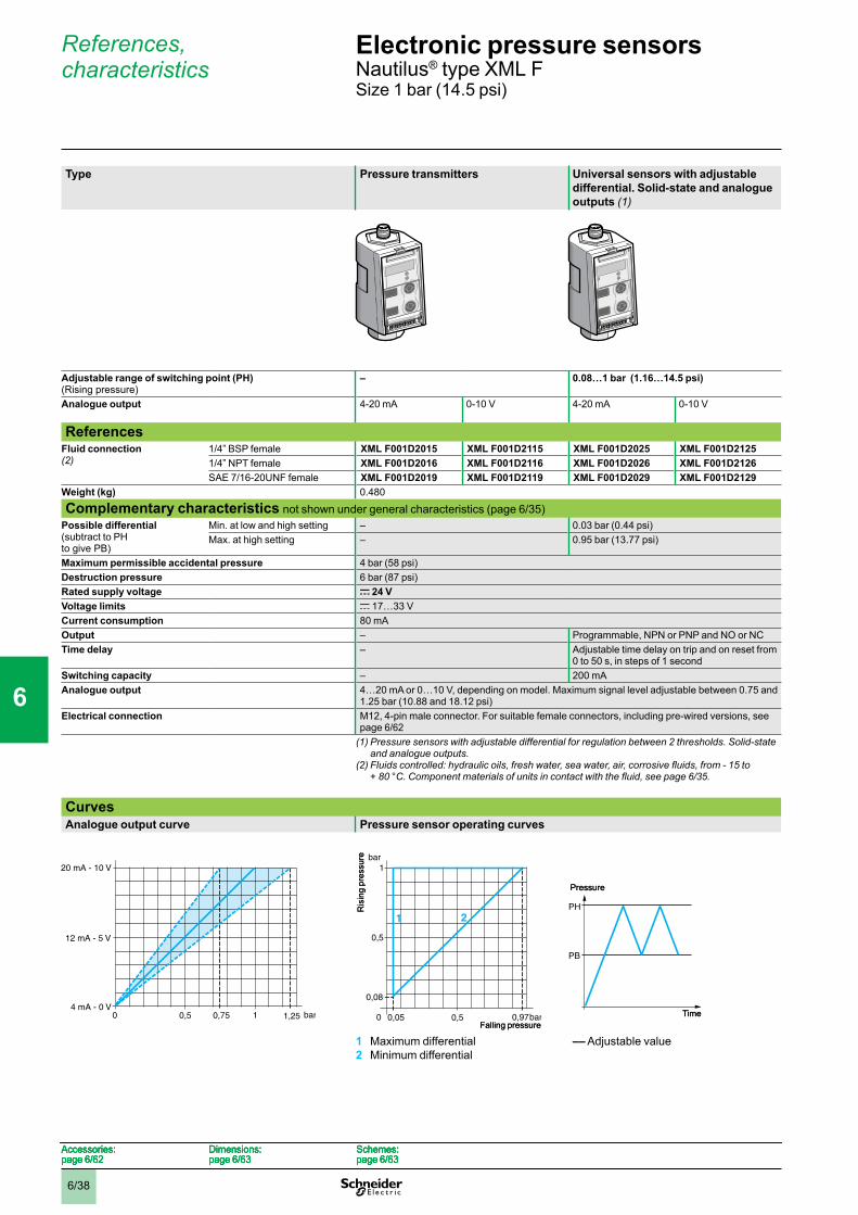
6/38
References, characteristics
Type Pressure transmitters Universal sensors with adjustable differential. Solid-state and analogue outputs (1)
Adjustable range of switching point (PH) (Rising pressure)
– 0.08…1 bar (1.16…14.5 psi)
Analogue output 4-20 mA 0-10 V 4-20 mA 0-10 V
ReferencesFluid connection (2)
1/4” BSP female XML F001D2015 XML F001D2115 XML F001D2025 XML F001D21251/4” NPT female XML F001D2016 XML F001D2116 XML F001D2026 XML F001D2126SAE 7/16-20UNF female XML F001D2019 XML F001D2119 XML F001D2029 XML F001D2129
Weight (kg) 0.480
Complementary characteristics not shown under general characteristics (page 6/35)Possible differential (subtract to PH to give PB)
Min. at low and high setting – 0.03 bar (0.44 psi)Max. at high setting – 0.95 bar (13.77 psi)
Maximum permissible accidental pressure 4 bar (58 psi)Destruction pressure 6 bar (87 psi)Rated supply voltage c 24 VVoltage limits c 17…33 VCurrent consumption 80 mAOutput – Programmable, NPN or PNP and NO or NCTime delay – Adjustable time delay on trip and on reset from
0 to 50 s, in steps of 1 secondSwitching capacity – 200 mAAnalogue output 4…20 mA or 0…10 V, depending on model. Maximum signal level adjustable between 0.75 and
1.25 bar (10.88 and 18.12 psi)Electrical connection M12, 4-pin male connector. For suitable female connectors, including pre-wired versions, see
page 6/62(1) Pressure sensors with adjustable differential for regulation between 2 thresholds. Solid-state
and analogue outputs.(2)Fluidscontrolled:hydraulicoils,freshwater,seawater,air,corrosivefluids,from-15to
+80°C.Componentmaterialsofunitsincontactwiththefluid,seepage6/35.
CurvesAnalogue output curve Pressure sensor operating curves
1 Maximum differential2 Minimum differential
–– Adjustable value
0,75 bar4 mA - 0 V
0,5 1,251
20 mA - 10 V
12 mA - 5 V
0 0,75 bar4 mA - 0 V
0,5 1,251
20 mA - 10 V
12 mA - 5 V
0
1
0,08
0,05 0,97bar
0,5
bar
0 0,5
21
Falling pressure
Ris
ing
pres
sure
1
0,08
0,05 0,97bar
0,5
bar
0 0,5
21
Falling pressure
Ris
ing
pres
sure
PH
PB
Pressure
Time
PH
PB
Pressure
Time
Accessories:page 6/62
Dimensions:page 6/63
Schemes:page 6/63
Accessories:page 6/62
Dimensions:page 6/63
Schemes:page 6/63
Accessories:page 6/62
Dimensions:page 6/63
Schemes:page 6/63
Accessories:page 6/62
Dimensions:page 6/63
Schemes:page 6/63
Electronic pressure sensors 0 Nautilus® type XML FSize 1 bar (14.5 psi)
1
2
3
4
5
6
7
8
9
10

6/39
References, characteristics (continued)
Type Pressure switches with adjustable differential and relay output (1)
Dual stage adjustable pressure switches with solid-state outputs (2)
Adjustable range of switching point(s) (PH or PH1 and PH2) (Rising pressure)
0.08…1 bar (1.16…14.5 psi)
ReferencesFluid connection (3)
1/4” BSP female XML F001E2045 XML F001D20351/4” NPT female XML F001E2046 XML F001D2036SAE 7/16-20UNF female XML F001E2049 XML F001D2039
Weight (kg) 0.590 0.480
Complementary characteristics not shown under general characteristics (page 6/35)Possible differential (subtract from:- PH to give PB- PH1 & PH2 to give PB1 & PB2)
Min. at low and high setting 0.03 bar (0.44 psi) For each stage: min. at low and high setting: 0.03 bar (0.44 psi)max. at high setting: 0.95 bar (13.77 psi)
Max. at high setting 0.95 bar (13.77 psi)
Maximum permissible accidental pressure 4 bar (58 psi)Destruction pressure 6 bar (87 psi)Rated supply voltage a 120 V c 24 VVoltage limits a 102…132 V c 17…33 VCurrent consumption 32 mA 80 mAOutput Relay Programmable, NPN or PNP and NO or NCTime delay Adjustable time delay on trip and on reset from 0 to 50 s, in steps of 1 secondSwitching capacity 2.5 A, AC-15, C300 (120 V - 1.5 A) 200 mAElectrical connection SAE 7/8-16UN, 5-pin male connector. For
suitable female pre-wired connectors, see page 6/62.
M12, 4-pin male connector. For suitable female connectors, including pre-wired versions, see page 6/62
(1) Pressure switches with adjustable differential for regulation between 2 thresholds. Relay output.
(2) Pressure switches with 2 adjustable stages and adjustable differential for each threshold. Solid-state outputs.
(3)Fluidscontrolled:hydraulicoils,freshwater,seawater,air,corrosivefluids,from-15to +80°C.Componentmaterialsofunitsincontactwiththefluid,seepage6/35.
Pressure switch operating curves(Curve for each stage for dual stage pressure switches) Pressure switches with relay output Dual stage pressure switches
1 Maximum differential2 Minimum differential
–– Adjustable value –– Adjustable value
1
0,08
0,05 0,97bar
0,5
bar
0 0,5
21
Falling pressure
Ris
ing
pres
sure
1
0,08
0,05 0,97bar
0,5
bar
0 0,5
21
Falling pressure
Ris
ing
pres
sure
PH
PB
Pressure
Time
PH
PB
Pressure
Time
PH2
PH1
PB1
PB2
Pressure
Time
PH2
PH1
PB1
PB2
Pressure
Time
Accessories:page 6/62
Dimensions:page 6/63
Schemes:page 6/63
Accessories:page 6/62
Dimensions:page 6/63
Schemes:page 6/63
Accessories:page 6/62
Dimensions:page 6/63
Schemes:page 6/63
Accessories:page 6/62
Dimensions:page 6/63
Schemes:page 6/63
Electronic pressure sensors 0 Nautilus® type XML FSize 1 bar (14.5 psi)
1
2
3
4
5
6
7
8
9
10

6/40
References, characteristics
2,5
0,20
0,12 2,42 bar
1
bar
0 1
21
2
2
PH
PB
Type Pressure transmitters Universal sensors with adjustable differential. Solid-state and analogue outputs (1)
Adjustable range of switching point (PH) (Rising pressure)
– 0.20…2.5 bar (2.9…36.25 psi)
Analogue output 4-20 mA 0-10 V 4-20 mA 0-10 V
ReferencesFluid connection (2)
1/4” BSP female XML F002D2015 XML F002D2115 XML F002D2025 XML F002D21251/4” NPT female XML F002D2016 XML F002D2116 XML F002D2026 XML F002D2126SAE 7/16-20UNF female XML F002D2019 XML F002D2119 XML F002D2029 XML F002D2129
Weight (kg) 0.480
Complementary characteristics not shown under general characteristics (page 6/35)Possible differential (subtract from PH to give PB)
Min. at low and high setting – 0.08 bar (1.09 psi) Max. at high setting – 2.38 bar (34.51 psi)
Maximum permissible accidental pressure 10 bar (145 psi)Destruction pressure 15 bar (217.5 psi)Rated supply voltage c 24 VVoltage limits c 17…33 VCurrent consumption 80 mAOutput – Programmable, NPN or PNP and NO or NCTime delay – Adjustable time delay on trip and on reset from
0 to 50 s, in steps of 1 secondSwitching capacity – 200 mAAnalogue output 4…20 mA or 0…10 V, depending on model. Maximum signal level adjustable between 1.9 and
3.1 bar (27.5 and 44.9 psi)Electrical connection M12, 4-pin male connector. For suitable female connectors, including pre-wired versions, see
page 6/62(1) Pressure sensors with adjustable differential for regulation between 2 thresholds. Solid-state
and analogue outputs.(2)Fluidscontrolled:hydraulicoils,freshwater,seawater,air,corrosivefluids,from-15to
+80°C.Componentmaterialsofunitsincontactwiththefluid,seepage6/35.
CurvesAnalogue output curve Pressure sensor operating curves
1 Maximum differential2 Minimum differential
–– Adjustable value
1 1,9 bar4 mA - 0 V
3,1
20 mA - 10 V
12 mA - 5 V
0 2,51 1,9 bar4 mA - 0 V
3,1
20 mA - 10 V
12 mA - 5 V
0 2,5
Ris
ing
pres
sure
Falling pressure
Ris
ing
pres
sure
Falling pressure
Pressure
Time
Pressure
Time
Accessories:page 6/62
Dimensions:page 6/63
Schemes:page 6/63
Accessories:page 6/62
Dimensions:page 6/63
Schemes:page 6/63
Accessories:page 6/62
Dimensions:page 6/63
Schemes:page 6/63
Accessories:page 6/62
Dimensions:page 6/63
Schemes:page 6/63
Electronic pressure sensors 0 Nautilus® type XML FSize 2.5 bar (36.25 psi)
1
2
3
4
5
6
7
8
9
10
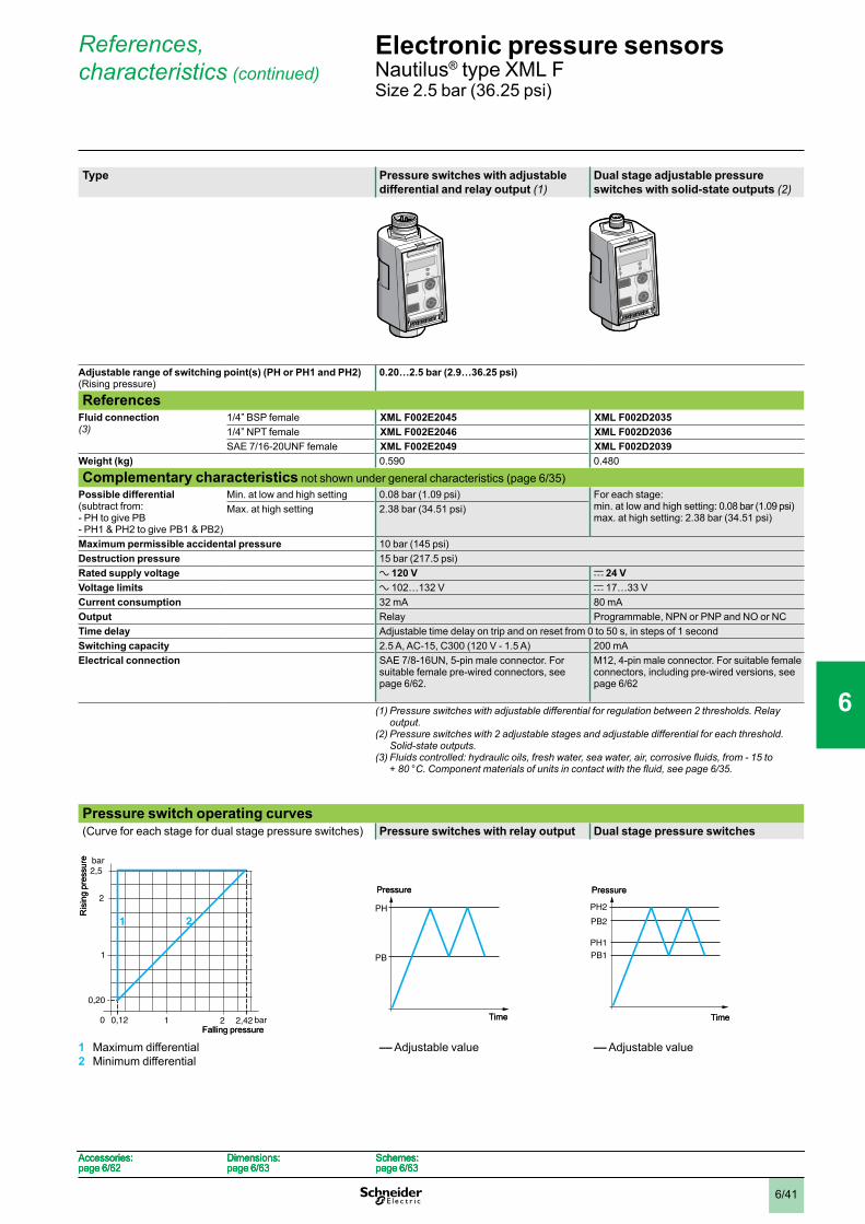
6/41
References, characteristics (continued)
2,5
0,20
0,12 2,42 bar
1
bar
0 1
21
2
2
PH
PB
PH2
PH1
PB1
PB2
Type Pressure switches with adjustable differential and relay output (1)
Dual stage adjustable pressure switches with solid-state outputs (2)
Adjustable range of switching point(s) (PH or PH1 and PH2) (Rising pressure)
0.20…2.5 bar (2.9…36.25 psi)
ReferencesFluid connection (3)
1/4” BSP female XML F002E2045 XML F002D20351/4” NPT female XML F002E2046 XML F002D2036SAE 7/16-20UNF female XML F002E2049 XML F002D2039
Weight (kg) 0.590 0.480
Complementary characteristics not shown under general characteristics (page 6/35)Possible differential (subtract from:- PH to give PB- PH1 & PH2 to give PB1 & PB2)
Min. at low and high setting 0.08 bar (1.09 psi) For each stage: min. at low and high setting: 0.08 bar (1.09 psi)max. at high setting: 2.38 bar (34.51 psi)
Max. at high setting 2.38 bar (34.51 psi)
Maximum permissible accidental pressure 10 bar (145 psi)Destruction pressure 15 bar (217.5 psi)Rated supply voltage a 120 V c 24 VVoltage limits a 102…132 V c 17…33 VCurrent consumption 32 mA 80 mAOutput Relay Programmable, NPN or PNP and NO or NCTime delay Adjustable time delay on trip and on reset from 0 to 50 s, in steps of 1 secondSwitching capacity 2.5 A, AC-15, C300 (120 V - 1.5 A) 200 mAElectrical connection SAE 7/8-16UN, 5-pin male connector. For
suitable female pre-wired connectors, see page 6/62.
M12, 4-pin male connector. For suitable female connectors, including pre-wired versions, see page 6/62
(1) Pressure switches with adjustable differential for regulation between 2 thresholds. Relay output.
(2) Pressure switches with 2 adjustable stages and adjustable differential for each threshold. Solid-state outputs.
(3)Fluidscontrolled:hydraulicoils,freshwater,seawater,air,corrosivefluids,from-15to +80°C.Componentmaterialsofunitsincontactwiththefluid,seepage6/35.
Pressure switch operating curves (Curve for each stage for dual stage pressure switches) Pressure switches with relay output Dual stage pressure switches
1 Maximum differential2 Minimum differential
–– Adjustable value –– Adjustable value
Ris
ing
pres
sure
Falling pressure
Ris
ing
pres
sure
Falling pressure
Pressure
Time
Pressure
Time
Pressure
Time
Pressure
Time
Accessories:page 6/62
Dimensions:page 6/63
Schemes:page 6/63
Accessories:page 6/62
Dimensions:page 6/63
Schemes:page 6/63
Accessories:page 6/62
Dimensions:page 6/63
Schemes:page 6/63
Accessories:page 6/62
Dimensions:page 6/63
Schemes:page 6/63
Electronic pressure sensors 0 Nautilus® type XML FSize 2.5 bar (36.25 psi)
1
2
3
4
5
6
7
8
9
10

6/42
References, characteristics
Type Pressure transmitters Universal sensors with adjustable differential. Solid-state and analogue outputs (1)
Adjustable range of switching point (PH) (Rising pressure)
– 0.8…10 bar (11.6…145 psi)
Analogue output 4-20 mA 0-10 V 4-20 mA 0-10 V
ReferencesFluid connection (2)
1/4” BSP female XML F010D2015 XML F010D2115 XML F010D2025 XML F010D21251/4” NPT female XML F010D2016 XML F010D2116 XML F010D2026 XML F010D2126SAE 7/16-20UNF female XML F010D2019 XML F010D2119 XML F010D2029 XML F010D2129
Weight (kg) 0.480
Complementary characteristics not shown under general characteristics (page 6/35)Possible differential (subtract from PH to give PB)
Min. at low and high setting – 0.3 bar (4.4 psi)Max. at high setting – 9.5 bar (137.75 psi)
Maximum permissible accidental pressure 40 bar (580 psi)Destruction pressure 60 bar (870 psi)Rated supply voltage c 24 VVoltage limits c 17…33 VCurrent consumption 80 mAOutput – Programmable, NPN or PNP and NO or NCTime delay – Adjustable time delay on trip and on reset from
0 to 50 s, in steps of 1 secondSwitching capacity – 200 mAAnalogue output 4…20 mA or 0…10 V, depending on model. Maximum signal level adjustable between 7.5 and
12.5 bar (108.75 and 181.25 psi)Electrical connection M12, 4-pin male connector. For suitable female connectors, including pre-wired versions, see
page 6/62(1) Pressure sensors with adjustable differential for regulation between 2 thresholds. Solid-state
and analogue outputs.(2)Fluidscontrolled:hydraulicoils,freshwater,seawater,air,corrosivefluids,from-15to
+80°C.Componentmaterialsofunitsincontactwiththefluid,seepage6/35.
CurvesAnalogue output curve Pressure sensor operating curves
1 Maximum differential2 Minimum differential
–– Adjustable value
7,5 bar4 mA - 0 V
5 12,510
20 mA - 10 V
12 mA - 5 V
0 7,5 bar4 mA - 0 V
5 12,510
20 mA - 10 V
12 mA - 5 V
0
10
0,8
0,5 9,7 bar
5
bar
0 5
21
Falling pressure
Ris
ing
pres
sure
10
0,8
0,5 9,7 bar
5
bar
0 5
21
Falling pressure
Ris
ing
pres
sure
PH
PB
Pressure
Time
PH
PB
Pressure
Time
Accessories:page 6/62
Dimensions:page 6/63
Schemes:page 6/63
Accessories:page 6/62
Dimensions:page 6/63
Schemes:page 6/63
Accessories:page 6/62
Dimensions:page 6/63
Schemes:page 6/63
Accessories:page 6/62
Dimensions:page 6/63
Schemes:page 6/63
Electronic pressure sensors 0 Nautilus® type XML FSize 10 bar (145 psi)
1
2
3
4
5
6
7
8
9
10
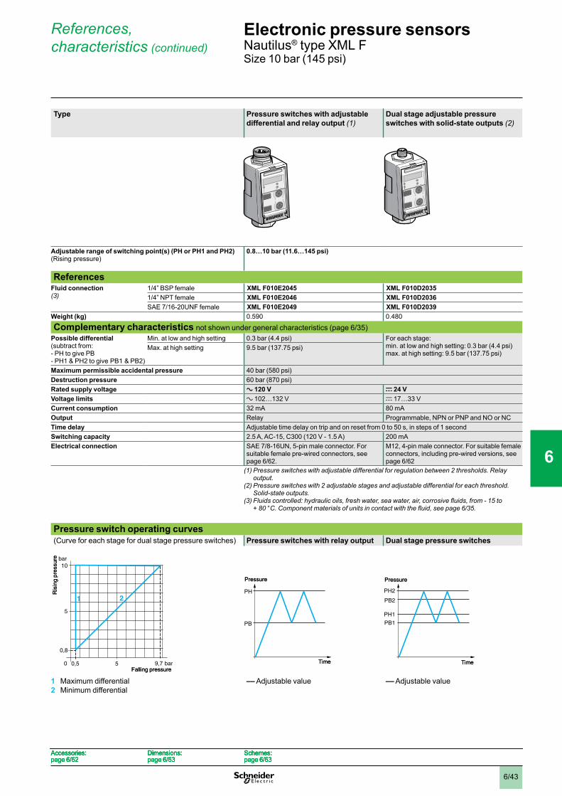
6/43
References, characteristics (continued)
Type Pressure switches with adjustable differential and relay output (1)
Dual stage adjustable pressure switches with solid-state outputs (2)
Adjustable range of switching point(s) (PH or PH1 and PH2) (Rising pressure)
0.8…10 bar (11.6…145 psi)
ReferencesFluid connection (3)
1/4” BSP female XML F010E2045 XML F010D20351/4” NPT female XML F010E2046 XML F010D2036SAE 7/16-20UNF female XML F010E2049 XML F010D2039
Weight (kg) 0.590 0.480
Complementary characteristics not shown under general characteristics (page 6/35)Possible differential (subtract from:- PH to give PB- PH1 & PH2 to give PB1 & PB2)
Min. at low and high setting 0.3 bar (4.4 psi) For each stage: min. at low and high setting: 0.3 bar (4.4 psi)max. at high setting: 9.5 bar (137.75 psi)
Max. at high setting 9.5 bar (137.75 psi)
Maximum permissible accidental pressure 40 bar (580 psi)Destruction pressure 60 bar (870 psi)Rated supply voltage a 120 V c 24 VVoltage limits a 102…132 V c 17…33 VCurrent consumption 32 mA 80 mAOutput Relay Programmable, NPN or PNP and NO or NCTime delay Adjustable time delay on trip and on reset from 0 to 50 s, in steps of 1 secondSwitching capacity 2.5 A, AC-15, C300 (120 V - 1.5 A) 200 mAElectrical connection SAE 7/8-16UN, 5-pin male connector. For
suitable female pre-wired connectors, see page 6/62.
M12, 4-pin male connector. For suitable female connectors, including pre-wired versions, see page 6/62
(1) Pressure switches with adjustable differential for regulation between 2 thresholds. Relay output.
(2) Pressure switches with 2 adjustable stages and adjustable differential for each threshold. Solid-state outputs.
(3)Fluidscontrolled:hydraulicoils,freshwater,seawater,air,corrosivefluids,from-15to +80°C.Componentmaterialsofunitsincontactwiththefluid,seepage6/35.
Pressure switch operating curves(Curve for each stage for dual stage pressure switches) Pressure switches with relay output Dual stage pressure switches
1 Maximum differential2 Minimum differential
–– Adjustable value –– Adjustable value
10
0,8
0,5 9,7 bar
5
bar
0 5
21
Falling pressure
Ris
ing
pres
sure
10
0,8
0,5 9,7 bar
5
bar
0 5
21
Falling pressure
Ris
ing
pres
sure
PH
PB
Pressure
Time
PH
PB
Pressure
Time
PH2
PH1
PB1
PB2
Pressure
Time
PH2
PH1
PB1
PB2
Pressure
Time
Accessories:page 6/62
Dimensions:page 6/63
Schemes:page 6/63
Accessories:page 6/62
Dimensions:page 6/63
Schemes:page 6/63
Accessories:page 6/62
Dimensions:page 6/63
Schemes:page 6/63
Accessories:page 6/62
Dimensions:page 6/63
Schemes:page 6/63
Electronic pressure sensors 0 Nautilus® type XML FSize 10 bar (145 psi)
1
2
3
4
5
6
7
8
9
10

6/44
References, characteristics
Type Pressure transmitters Universal sensors with adjustable differential. Solid-state and analogue outputs (1)
Adjustable range of switching point (PH) (Rising pressure)
– 1.28…16 bar (18.56…232 psi)
Analogue output 4-20 mA 0-10 V 4-20 mA 0-10 V
ReferencesFluid connection (2)
1/4” BSP female XML F016D2015 XML F016D2115 XML F016D2025 XML F016D21251/4” NPT female XML F016D2016 XML F016D2116 XML F016D2026 XML F016D2126SAE 7/16-20UNF female XML F016D2019 XML F016D2119 XML F016D2029 XML F016D2129
Weight (kg) 0.480
Complementary characteristics not shown under general characteristics (page 6/35)Possible differential (subtract from PH to give PB)
Min. at low and high setting – 0.48 bar (6.96 psi) Max. at high setting – 15.2 bar (220.4 psi)
Maximum permissible accidental pressure 64 bar (928 psi)Destruction pressure 96 bar (1392 psi)Rated supply voltage c 24 VVoltage limits c 17…33 VCurrent consumption 80 mAOutput – Programmable, NPN or PNP and NO or NCTime delay – Adjustable time delay on trip and on reset from
0 to 50 s, in steps of 1 secondSwitching capacity – 200 mAAnalogue output 4…20 mA or 0…10 V, depending on model. Maximum signal level adjustable between 12 and
20 bar (174 and 290 psi)Electrical connection M12, 4-pin male connector. For suitable female connectors, including pre-wired versions, see
page 6/62(1) Pressure sensors with adjustable differential for regulation between 2 thresholds. Solid-state
and analogue outputs.(2)Fluidscontrolled:hydraulicoils,freshwater,seawater,air,corrosivefluids,from-15to
+80°C.Componentmaterialsofunitsincontactwiththefluid,seepage6/35.
CurvesAnalogue output curve Pressure sensor operating curves
1 Maximum differential2 Minimum differential
–– Adjustable value
1610 bar4 mA - 0 V
20 mA - 10 V
12 mA - 5 V
0 12 201610 bar4 mA - 0 V
20 mA - 10 V
12 mA - 5 V
0 12 20 15,5
16
1,28
0,8 bar
10
bar
0 10
21Ris
ing
pres
sure
Falling pressure15,5
16
1,28
0,8 bar
10
bar
0 10
21Ris
ing
pres
sure
Falling pressure
PH
PB
Pressure
Time
PH
PB
Pressure
Time
Accessories:page 6/62
Dimensions:page 6/63
Schemes:page 6/63
Accessories:page 6/62
Dimensions:page 6/63
Schemes:page 6/63
Accessories:page 6/62
Dimensions:page 6/63
Schemes:page 6/63
Accessories:page 6/62
Dimensions:page 6/63
Schemes:page 6/63
Electronic pressure sensors 0 Nautilus® type XML FSize 16 bar (232 psi)
1
2
3
4
5
6
7
8
9
10
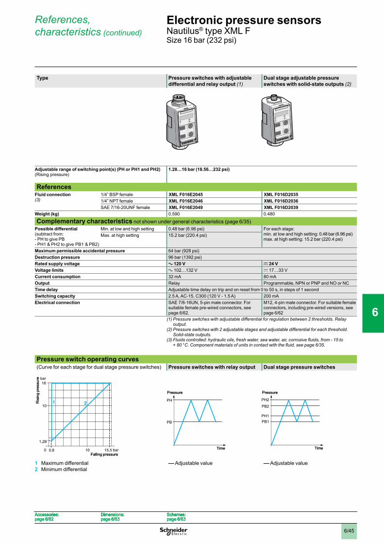
6/45
References, characteristics (continued)
Type Pressure switches with adjustable differential and relay output (1)
Dual stage adjustable pressure switches with solid-state outputs (2)
Adjustable range of switching point(s) (PH or PH1 and PH2) (Rising pressure)
1.28…16 bar (18.56…232 psi)
ReferencesFluid connection (3)
1/4” BSP female XML F016E2045 XML F016D20351/4” NPT female XML F016E2046 XML F016D2036SAE 7/16-20UNF female XML F016E2049 XML F016D2039
Weight (kg) 0.590 0.480
Complementary characteristics not shown under general characteristics (page 6/35)Possible differential (subtract from:- PH to give PB - PH1 & PH2 to give PB1 & PB2)
Min. at low and high setting 0.48 bar (6.96 psi) For each stage: min. at low and high setting: 0.48 bar (6.96 psi)max. at high setting: 15.2 bar (220.4 psi)
Max. at high setting 15.2 bar (220.4 psi)
Maximum permissible accidental pressure 64 bar (928 psi)Destruction pressure 96 bar (1392 psi)Rated supply voltage a 120 V c 24 VVoltage limits a 102…132 V c 17…33 VCurrent consumption 32 mA 80 mAOutput Relay Programmable, NPN or PNP and NO or NCTime delay Adjustable time delay on trip and on reset from 0 to 50 s, in steps of 1 secondSwitching capacity 2.5 A, AC-15, C300 (120 V - 1.5 A) 200 mAElectrical connection SAE 7/8-16UN, 5-pin male connector. For
suitable female pre-wired connectors, see page 6/62.
M12, 4-pin male connector. For suitable female connectors, including pre-wired versions, see page 6/62
(1) Pressure switches with adjustable differential for regulation between 2 thresholds. Relay output.
(2) Pressure switches with 2 adjustable stages and adjustable differential for each threshold. Solid-state outputs.
(3)Fluidscontrolled:hydraulicoils,freshwater,seawater,air,corrosivefluids,from-15to +80°C.Componentmaterialsofunitsincontactwiththefluid,seepage6/35.
Pressure switch operating curves(Curve for each stage for dual stage pressure switches) Pressure switches with relay output Dual stage pressure switches
1 Maximum differential2 Minimum differential
–– Adjustable value –– Adjustable value
15,5
16
1,28
0,8 bar
10
bar
0 10
21Ris
ing
pres
sure
Falling pressure15,5
16
1,28
0,8 bar
10
bar
0 10
21Ris
ing
pres
sure
Falling pressure
PH
PB
Pressure
Time
PH
PB
Pressure
Time
PH2
PH1
PB1
PB2
Pressure
Time
PH2
PH1
PB1
PB2
Pressure
Time
Accessories:page 6/62
Dimensions:page 6/63
Schemes:page 6/63
Accessories:page 6/62
Dimensions:page 6/63
Schemes:page 6/63
Accessories:page 6/62
Dimensions:page 6/63
Schemes:page 6/63
Accessories:page 6/62
Dimensions:page 6/63
Schemes:page 6/63
Electronic pressure sensors 0 Nautilus® type XML FSize 16 bar (232 psi)
1
2
3
4
5
6
7
8
9
10
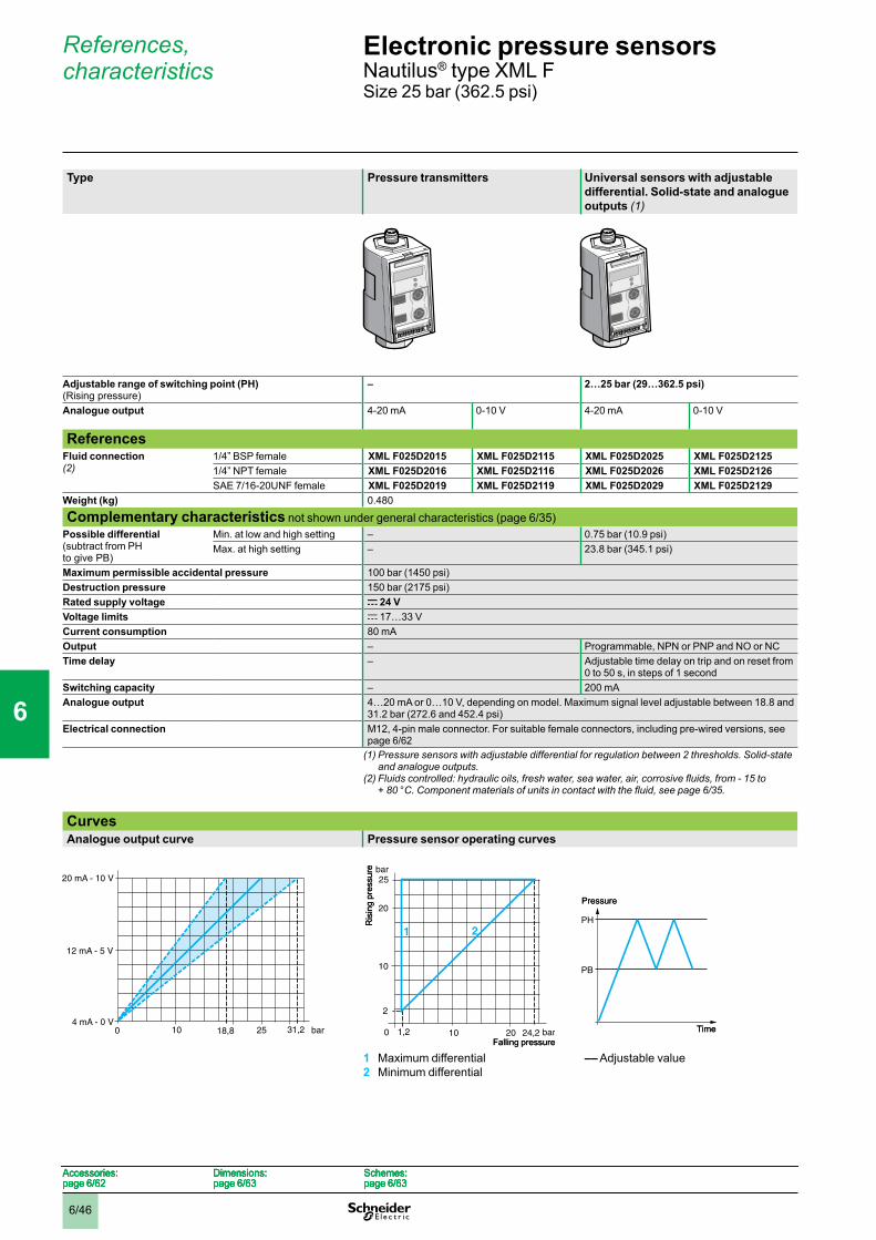
6/46
References, characteristics
Type Pressure transmitters Universal sensors with adjustable differential. Solid-state and analogue outputs (1)
Adjustable range of switching point (PH) (Rising pressure)
– 2…25 bar (29…362.5 psi)
Analogue output 4-20 mA 0-10 V 4-20 mA 0-10 V
ReferencesFluid connection (2)
1/4” BSP female XML F025D2015 XML F025D2115 XML F025D2025 XML F025D21251/4” NPT female XML F025D2016 XML F025D2116 XML F025D2026 XML F025D2126SAE 7/16-20UNF female XML F025D2019 XML F025D2119 XML F025D2029 XML F025D2129
Weight (kg) 0.480
Complementary characteristics not shown under general characteristics (page 6/35)Possible differential (subtract from PH to give PB)
Min. at low and high setting – 0.75 bar (10.9 psi)Max. at high setting – 23.8 bar (345.1 psi)
Maximum permissible accidental pressure 100 bar (1450 psi)Destruction pressure 150 bar (2175 psi)Rated supply voltage c 24 VVoltage limits c 17…33 VCurrent consumption 80 mAOutput – Programmable, NPN or PNP and NO or NCTime delay – Adjustable time delay on trip and on reset from
0 to 50 s, in steps of 1 secondSwitching capacity – 200 mAAnalogue output 4…20 mA or 0…10 V, depending on model. Maximum signal level adjustable between 18.8 and
31.2 bar (272.6 and 452.4 psi)Electrical connection M12, 4-pin male connector. For suitable female connectors, including pre-wired versions, see
page 6/62(1) Pressure sensors with adjustable differential for regulation between 2 thresholds. Solid-state
and analogue outputs.(2)Fluidscontrolled:hydraulicoils,freshwater,seawater,air,corrosivefluids,from-15to
+80°C.Componentmaterialsofunitsincontactwiththefluid,seepage6/35.
CurvesAnalogue output curve Pressure sensor operating curves
1 Maximum differential2 Minimum differential
–– Adjustable value
10 18,8 bar4 mA - 0 V
31,2
20 mA - 10 V
12 mA - 5 V
0 2510 18,8 bar4 mA - 0 V
31,2
20 mA - 10 V
12 mA - 5 V
0 25
25
2
1,2 24,2 bar
10
bar
0 10
21
20
20
Ris
ing
pres
sure
Falling pressure
25
2
1,2 24,2 bar
10
bar
0 10
21
20
20
Ris
ing
pres
sure
Falling pressure
PH
PB
Pressure
Time
PH
PB
Pressure
Time
Accessories:page 6/62
Dimensions:page 6/63
Schemes:page 6/63
Accessories:page 6/62
Dimensions:page 6/63
Schemes:page 6/63
Accessories:page 6/62
Dimensions:page 6/63
Schemes:page 6/63
Accessories:page 6/62
Dimensions:page 6/63
Schemes:page 6/63
Electronic pressure sensors 0 Nautilus® type XML FSize 25 bar (362.5 psi)
1
2
3
4
5
6
7
8
9
10
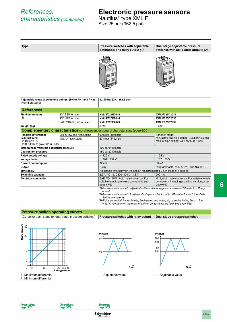
6/47
References, characteristics (continued)
Type Pressure switches with adjustable differential and relay output (1)
Dual stage adjustable pressure switches with solid-state outputs (2)
Adjustable range of switching point(s) (PH or PH1 and PH2) (Rising pressure)
2…25 bar (29…362.5 psi)
ReferencesFluid connection (3)
1/4” BSP female XML F025E2045 XML F025D20351/4” NPT female XML F025E2046 XML F025D2036SAE 7/16-20UNF female XML F025E2049 XML F025D2039
Weight (kg) 0.590 0.480
Complementary characteristics not shown under general characteristics (page 6/35)Possible differential (subtract from:- PH to give PB- PH1 & PH2 to give PB1 & PB2)
Min. at low and high setting 0.75 bar (10.9 psi) For each stage: min. at low and high setting: 0.75 bar (10.9 psi)max. at high setting: 23.8 bar (345.1 psi)
Max. at high setting 23.8 bar (345.1 psi)
Maximum permissible accidental pressure 100 bar (1450 psi)Destruction pressure 150 bar (2175 psi)Rated supply voltage a 120 V c 24 VVoltage limits a 102…132 V c 17…33 VCurrent consumption 32 mA 80 mAOutput Relay Programmable, NPN or PNP and NO or NCTime delay Adjustable time delay on trip and on reset from 0 to 50 s, in steps of 1 secondSwitching capacity 2.5 A, AC-15, C300 (120 V - 1.5 A) 200 mAElectrical connection SAE 7/8-16UN, 5-pin male connector. For
suitable female pre-wired connectors, see page 6/62.
M12, 4-pin male connector. For suitable female connectors, including pre-wired versions, see page 6/62
(1) Pressure switches with adjustable differential for regulation between 2 thresholds. Relay output.
(2) Pressure switches with 2 adjustable stages and adjustable differential for each threshold. Solid-state outputs.
(3)Fluidscontrolled:hydraulicoils,freshwater,seawater,air,corrosivefluids,from-15to +80°C.Componentmaterialsofunitsincontactwiththefluid,seepage6/35.
Pressure switch operating curves(Curve for each stage for dual stage pressure switches) Pressure switches with relay output Dual stage pressure switches
1 Maximum differential2 Minimum differential
–– Adjustable value –– Adjustable value
25
2
1,2 24,2 bar
10
bar
0 10
21
20
20
Ris
ing
pres
sure
Falling pressure
25
2
1,2 24,2 bar
10
bar
0 10
21
20
20
Ris
ing
pres
sure
Falling pressure
PH
PB
Pressure
Time
PH
PB
Pressure
Time
PH2
PH1
PB1
PB2
Pressure
Time
PH2
PH1
PB1
PB2
Pressure
Time
Accessories:page 6/62
Dimensions:page 6/63
Schemes:page 6/63
Accessories:page 6/62
Dimensions:page 6/63
Schemes:page 6/63
Accessories:page 6/62
Dimensions:page 6/63
Schemes:page 6/63
Accessories:page 6/62
Dimensions:page 6/63
Schemes:page 6/63
Electronic pressure sensors 0 Nautilus® type XML FSize 25 bar (362.5 psi)
1
2
3
4
5
6
7
8
9
10
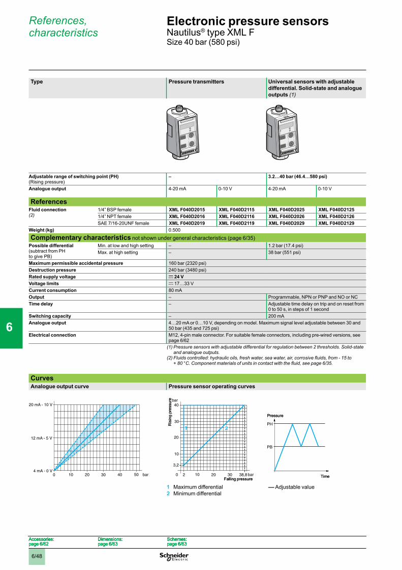
6/48
References, characteristics
Type Pressure transmitters Universal sensors with adjustable differential. Solid-state and analogue outputs (1)
Adjustable range of switching point (PH) (Rising pressure)
– 3.2…40 bar (46.4…580 psi)
Analogue output 4-20 mA 0-10 V 4-20 mA 0-10 V
ReferencesFluid connection (2)
1/4” BSP female XML F040D2015 XML F040D2115 XML F040D2025 XML F040D21251/4” NPT female XML F040D2016 XML F040D2116 XML F040D2026 XML F040D2126SAE 7/16-20UNF female XML F040D2019 XML F040D2119 XML F040D2029 XML F040D2129
Weight (kg) 0.500
Complementary characteristics not shown under general characteristics (page 6/35)Possible differential (subtract from PH to give PB)
Min. at low and high setting – 1.2 bar (17.4 psi)Max. at high setting – 38 bar (551 psi)
Maximum permissible accidental pressure 160 bar (2320 psi)Destruction pressure 240 bar (3480 psi)Rated supply voltage c 24 VVoltage limits c 17…33 VCurrent consumption 80 mAOutput – Programmable, NPN or PNP and NO or NCTime delay – Adjustable time delay on trip and on reset from
0 to 50 s, in steps of 1 secondSwitching capacity – 200 mAAnalogue output 4…20 mA or 0…10 V, depending on model. Maximum signal level adjustable between 30 and
50 bar (435 and 725 psi)Electrical connection M12, 4-pin male connector. For suitable female connectors, including pre-wired versions, see
page 6/62(1) Pressure sensors with adjustable differential for regulation between 2 thresholds. Solid-state
and analogue outputs.(2)Fluidscontrolled:hydraulicoils,freshwater,seawater,air,corrosivefluids,from-15to
+80°C.Componentmaterialsofunitsincontactwiththefluid,seepage6/35.
CurvesAnalogue output curve Pressure sensor operating curves
1 Maximum differential2 Minimum differential
–– Adjustable value
10 20 30 bar4 mA - 0 V
40
20 mA - 10 V
12 mA - 5 V
0 5010 20 30 bar4 mA - 0 V
40
20 mA - 10 V
12 mA - 5 V
0 50
10
30
10
40
3,2
2 38,8 bar
20
20
bar
0
1
30
2
Ris
ing
pres
sure
Falling pressure
10
30
10
40
3,2
2 38,8 bar
20
20
bar
0
1
30
2
Ris
ing
pres
sure
Falling pressure
PH
PB
Pressure
Time
PH
PB
Pressure
Time
Accessories:page 6/62
Dimensions:page 6/63
Schemes:page 6/63
Accessories:page 6/62
Dimensions:page 6/63
Schemes:page 6/63
Accessories:page 6/62
Dimensions:page 6/63
Schemes:page 6/63
Accessories:page 6/62
Dimensions:page 6/63
Schemes:page 6/63
Electronic pressure sensors 0 Nautilus® type XML FSize 40 bar (580 psi)
1
2
3
4
5
6
7
8
9
10
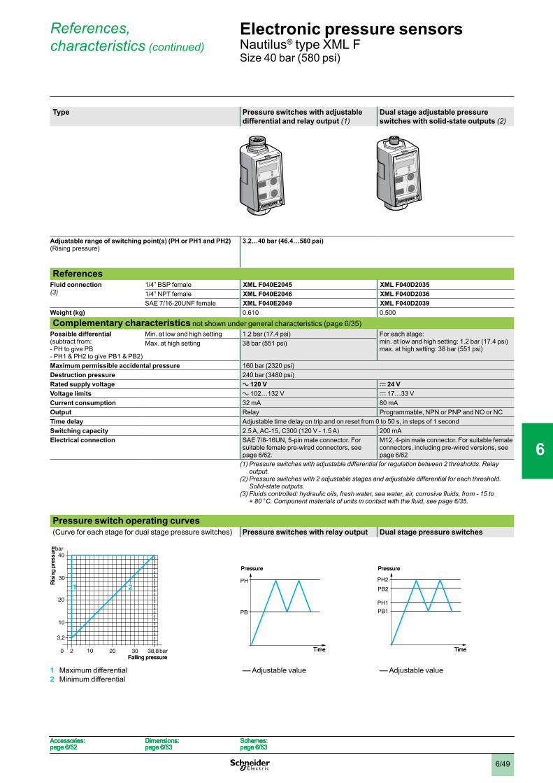
6/49
References, characteristics (continued)
Type Pressure switches with adjustable differential and relay output (1)
Dual stage adjustable pressure switches with solid-state outputs (2)
Adjustable range of switching point(s) (PH or PH1 and PH2) (Rising pressure)
3.2…40 bar (46.4…580 psi)
ReferencesFluid connection (3)
1/4” BSP female XML F040E2045 XML F040D20351/4” NPT female XML F040E2046 XML F040D2036SAE 7/16-20UNF female XML F040E2049 XML F040D2039
Weight (kg) 0.610 0.500
Complementary characteristics not shown under general characteristics (page 6/35)Possible differential (subtract from:- PH to give PB- PH1 & PH2 to give PB1 & PB2)
Min. at low and high setting 1.2 bar (17.4 psi) For each stage: min. at low and high setting: 1.2 bar (17.4 psi)max. at high setting: 38 bar (551 psi)
Max. at high setting 38 bar (551 psi)
Maximum permissible accidental pressure 160 bar (2320 psi)Destruction pressure 240 bar (3480 psi)Rated supply voltage a 120 V c 24 VVoltage limits a 102…132 V c 17…33 VCurrent consumption 32 mA 80 mAOutput Relay Programmable, NPN or PNP and NO or NCTime delay Adjustable time delay on trip and on reset from 0 to 50 s, in steps of 1 secondSwitching capacity 2.5 A, AC-15, C300 (120 V - 1.5 A) 200 mAElectrical connection SAE 7/8-16UN, 5-pin male connector. For
suitable female pre-wired connectors, see page 6/62.
M12, 4-pin male connector. For suitable female connectors, including pre-wired versions, see page 6/62
(1) Pressure switches with adjustable differential for regulation between 2 thresholds. Relay output.
(2) Pressure switches with 2 adjustable stages and adjustable differential for each threshold. Solid-state outputs.
(3)Fluidscontrolled:hydraulicoils,freshwater,seawater,air,corrosivefluids,from-15to +80°C.Componentmaterialsofunitsincontactwiththefluid,seepage6/35.
Pressure switch operating curves(Curve for each stage for dual stage pressure switches) Pressure switches with relay output Dual stage pressure switches
1 Maximum differential2 Minimum differential
–– Adjustable value –– Adjustable value
10
30
10
40
3,2
2 38,8 bar
20
20
bar
0
1
30
2
Ris
ing
pres
sure
Falling pressure
10
30
10
40
3,2
2 38,8 bar
20
20
bar
0
1
30
2
Ris
ing
pres
sure
Falling pressure
PH
PB
Pressure
Time
PH
PB
Pressure
Time
PH2
PH1
PB1
PB2
Pressure
Time
PH2
PH1
PB1
PB2
Pressure
Time
Accessories:page 6/62
Dimensions:page 6/63
Schemes:page 6/63
Accessories:page 6/62
Dimensions:page 6/63
Schemes:page 6/63
Accessories:page 6/62
Dimensions:page 6/63
Schemes:page 6/63
Accessories:page 6/62
Dimensions:page 6/63
Schemes:page 6/63
Electronic pressure sensors 0 Nautilus® type XML FSize 40 bar (580 psi)
1
2
3
4
5
6
7
8
9
10

6/50
References, characteristics
Type Pressure transmitters Universal sensors with adjustable differential. Solid-state and analogue outputs (1)
Adjustable range of switching point (PH) (Rising pressure)
– 5.6…70 bar (81.2…1015 psi)
Analogue output 4-20 mA 0-10 V 4-20 mA 0-10 V
ReferencesFluid connection (2)
1/4” BSP female XML F070D2015 XML F070D2115 XML F070D2025 XML F070D21251/4” NPT female XML F070D2016 XML F070D2116 XML F070D2026 XML F070D2126SAE 7/16-20UNF female XML F070D2019 XML F070D2119 XML F070D2029 XML F070D2129
Weight (kg) 0.500
Complementary characteristics not shown under general characteristics (page 6/35)Possible differential (subtract from PH to give PB)
Min. at low and high setting – 2.1 bar (30.5 psi)Max. at high setting – 66.5 bar (964.2 psi)
Maximum permissible accidental pressure 280 bar (4060 psi)Destruction pressure 420 bar (6090 psi)Rated supply voltage c 24 VVoltage limits c 17…33 VCurrent consumption 80 mAOutput – Programmable, NPN or PNP and NO or NCTime delay – Adjustable time delay on trip and on reset from
0 to 50 s, in steps of 1 secondSwitching capacity – 200 mAAnalogue output 4…20 mA or 0…10 V, depending on model. Maximum signal level adjustable between 52.5 and
87.5 bar (761.3 and 1268.7 psi)Electrical connection M12, 4-pin male connector. For suitable female connectors, including pre-wired versions, see
page 6/62(1) Pressure sensors with adjustable differential for regulation between 2 thresholds. Solid-state
and analogue outputs.(2)Fluidscontrolled:hydraulicoils,freshwater,seawater,air,corrosivefluids,from-15to
+80°C.Componentmaterialsofunitsincontactwiththefluid,seepage6/35.
CurvesAnalogue output curve Pressure sensor operating curves
1 Maximum differential2 Minimum differential
–– Adjustable value
20 52,5 bar4 mA - 0 V
87,5
20 mA - 10 V
12 mA - 5 V
0 7020 52,5 bar4 mA - 0 V
87,5
20 mA - 10 V
12 mA - 5 V
0 70
70
5,6
3,5 67,9 bar
50
bar
0 50
21
20
20
Ris
ing
pres
sure
Falling pressure
70
5,6
3,5 67,9 bar
50
bar
0 50
21
20
20
Ris
ing
pres
sure
Falling pressure
PH
PB
Pressure
Time
PH
PB
Pressure
Time
Accessories:page 6/62
Dimensions:page 6/63
Schemes:page 6/63
Accessories:page 6/62
Dimensions:page 6/63
Schemes:page 6/63
Accessories:page 6/62
Dimensions:page 6/63
Schemes:page 6/63
Accessories:page 6/62
Dimensions:page 6/63
Schemes:page 6/63
Electronic pressure sensors 0 Nautilus® type XML FSize 70 bar (1015 psi)
1
2
3
4
5
6
7
8
9
10

6/51
References, characteristics (continued)
Type Pressure switches with adjustable differential and relay output (1)
Dual stage adjustable pressure switches with solid-state outputs (2)
Adjustable range of switching point(s) (PH or PH1 and PH2) (Rising pressure)
5.6…70 bar (81.2…1015 psi)
ReferencesFluid connection (3)
1/4” BSP female XML F070E2045 XML F070D20351/4” NPT female XML F070E2046 XML F070D2036SAE 7/16-20UNF female XML F070E2049 XML F070D2039
Weight (kg) 0.610 0.500
Complementary characteristics not shown under general characteristics (page 6/35)Possible differential (subtract from:- PH to give PB- PH1 & PH2 to give PB1 & PB2)
Min. at low and high setting 2.1 bar (30.5 psi) For each stage: min. at low and high setting: 2.1 bar (30.5 psi)max. at high setting: 66.5 bar (964.2 psi)
Max. at high setting 66.5 bar (964.2 psi)
Maximum permissible accidental pressure 280 bar (4060 psi)Destruction pressure 420 bar (6090 psi)Rated supply voltage a 120 V c 24 VVoltage limits a 102…132 V c 17…33 VCurrent consumption 32 mA 80 mAOutput Relay Programmable, NPN or PNP and NO or NCTime delay Adjustable time delay on trip and on reset from 0 to 50 s, in steps of 1 secondSwitching capacity 2.5 A, AC-15, C300 (120 V - 1.5 A) 200 mAElectrical connection SAE 7/8-16UN, 5-pin male connector. For
suitable female pre-wired connectors, see page 6/62.
M12, 4-pin male connector. For suitable female connectors, including pre-wired versions, see page 6/62
(1) Pressure switches with adjustable differential for regulation between 2 thresholds. Relay output.
(2) Pressure switches with 2 adjustable stages and adjustable differential for each threshold. Solid-state outputs.
(3)Fluidscontrolled:hydraulicoils,freshwater,seawater,air,corrosivefluids,from-15to +80°C.Componentmaterialsofunitsincontactwiththefluid,seepage6/35.
Pressure switch operating curves(Curve for each stage for dual stage pressure switches) Pressure switches with relay output Dual stage pressure switches
1 Maximum differential2 Minimum differential
–– Adjustable value –– Adjustable value
70
5,6
3,5 67,9 bar
50
bar
0 50
21
20
20
Ris
ing
pres
sure
Falling pressure
70
5,6
3,5 67,9 bar
50
bar
0 50
21
20
20
Ris
ing
pres
sure
Falling pressure
PH
PB
Pressure
Time
PH
PB
Pressure
Time
PH2
PH1
PB1
PB2
Pressure
Time
PH2
PH1
PB1
PB2
Pressure
Time
Accessories:page 6/62
Dimensions:page 6/63
Schemes:page 6/63
Accessories:page 6/62
Dimensions:page 6/63
Schemes:page 6/63
Accessories:page 6/62
Dimensions:page 6/63
Schemes:page 6/63
Accessories:page 6/62
Dimensions:page 6/63
Schemes:page 6/63
Electronic pressure sensors 0 Nautilus® type XML FSize 70 bar (1015 psi)
1
2
3
4
5
6
7
8
9
10
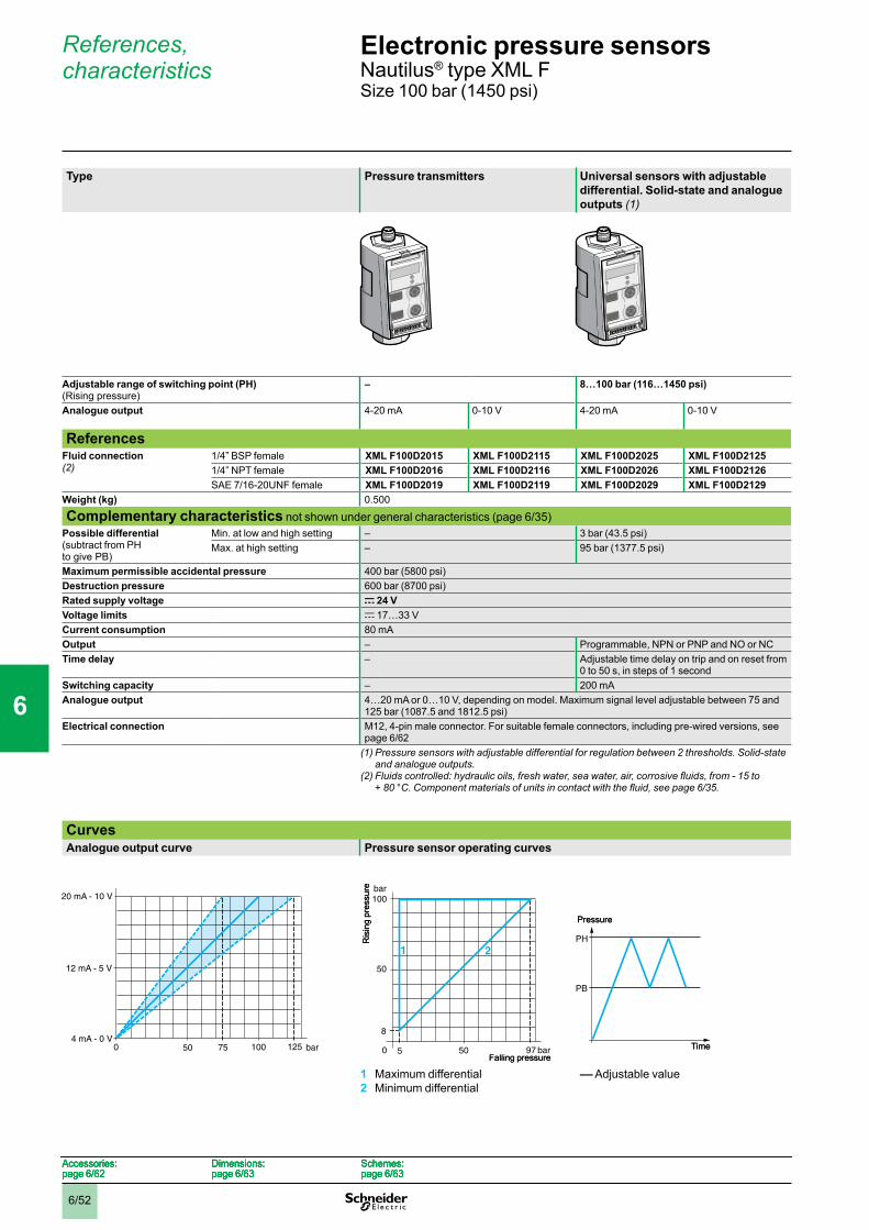
6/52
References, characteristics
Type Pressure transmitters Universal sensors with adjustable differential. Solid-state and analogue outputs (1)
Adjustable range of switching point (PH) (Rising pressure)
– 8…100 bar (116…1450 psi)
Analogue output 4-20 mA 0-10 V 4-20 mA 0-10 V
ReferencesFluid connection (2)
1/4” BSP female XML F100D2015 XML F100D2115 XML F100D2025 XML F100D21251/4” NPT female XML F100D2016 XML F100D2116 XML F100D2026 XML F100D2126SAE 7/16-20UNF female XML F100D2019 XML F100D2119 XML F100D2029 XML F100D2129
Weight (kg) 0.500
Complementary characteristics not shown under general characteristics (page 6/35)Possible differential (subtract from PH to give PB)
Min. at low and high setting – 3 bar (43.5 psi)Max. at high setting – 95 bar (1377.5 psi)
Maximum permissible accidental pressure 400 bar (5800 psi)Destruction pressure 600 bar (8700 psi)Rated supply voltage c 24 VVoltage limits c 17…33 VCurrent consumption 80 mAOutput – Programmable, NPN or PNP and NO or NCTime delay – Adjustable time delay on trip and on reset from
0 to 50 s, in steps of 1 secondSwitching capacity – 200 mAAnalogue output 4…20 mA or 0…10 V, depending on model. Maximum signal level adjustable between 75 and
125 bar (1087.5 and 1812.5 psi)Electrical connection M12, 4-pin male connector. For suitable female connectors, including pre-wired versions, see
page 6/62(1) Pressure sensors with adjustable differential for regulation between 2 thresholds. Solid-state
and analogue outputs.(2)Fluidscontrolled:hydraulicoils,freshwater,seawater,air,corrosivefluids,from-15to
+80°C.Componentmaterialsofunitsincontactwiththefluid,seepage6/35.
CurvesAnalogue output curve Pressure sensor operating curves
1 Maximum differential2 Minimum differential
–– Adjustable value
75 bar4 mA - 0 V
50 125100
20 mA - 10 V
12 mA - 5 V
0 75 bar4 mA - 0 V
50 125100
20 mA - 10 V
12 mA - 5 V
0
100
8
5 97 bar
50
bar
0 50
21
Ris
ing
pres
sure
Falling pressure
100
8
5 97 bar
50
bar
0 50
21
Ris
ing
pres
sure
Falling pressure
PH
PB
Pressure
Time
PH
PB
Pressure
Time
Accessories:page 6/62
Dimensions:page 6/63
Schemes:page 6/63
Accessories:page 6/62
Dimensions:page 6/63
Schemes:page 6/63
Accessories:page 6/62
Dimensions:page 6/63
Schemes:page 6/63
Accessories:page 6/62
Dimensions:page 6/63
Schemes:page 6/63
Electronic pressure sensors 0 Nautilus® type XML FSize 100 bar (1450 psi)
1
2
3
4
5
6
7
8
9
10
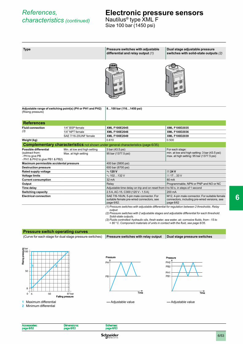
6/53
References, characteristics (continued)
Type Pressure switches with adjustable differential and relay output (1)
Dual stage adjustable pressure switches with solid-state outputs (2)
Adjustable range of switching point(s) (PH or PH1 and PH2) (Rising pressure)
8…100 bar (116…1450 psi)
ReferencesFluid connection (3)
1/4” BSP female XML F100E2045 XML F100D20351/4” NPT female XML F100E2046 XML F100D2036SAE 7/16-20UNF female XML F100E2049 XML F100D2039
Weight (kg) 0.610 0.500
Complementary characteristics not shown under general characteristics (page 6/35)Possible differential (subtract from:- PH to give PB- PH1 & PH2 to give PB1 & PB2)
Min. at low and high setting 3 bar (43.5 psi) For each stage: min. at low and high setting: 3 bar (43.5 psi)max. at high setting: 95 bar (1377.5 psi)
Max. at high setting 95 bar (1377.5 psi)
Maximum permissible accidental pressure 400 bar (5800 psi)Destruction pressure 600 bar (8700 psi)Rated supply voltage a 120 V c 24 VVoltage limits a 102…132 V c 17…33 VCurrent consumption 32 mA 80 mAOutput Relay Programmable, NPN or PNP and NO or NCTime delay Adjustable time delay on trip and on reset from 0 to 50 s, in steps of 1 secondSwitching capacity 2.5 A, AC-15, C300 (120 V - 1.5 A) 200 mAElectrical connection SAE 7/8-16UN, 5-pin male connector. For
suitable female pre-wired connectors, see page 6/62.
M12, 4-pin male connector. For suitable female connectors, including pre-wired versions, see page 6/62
(1) Pressure switches with adjustable differential for regulation between 2 thresholds. Relay output.
(2) Pressure switches with 2 adjustable stages and adjustable differential for each threshold. Solid-state outputs.
(3)Fluidscontrolled:hydraulicoils,freshwater,seawater,air,corrosivefluids,from-15to +80°C.Componentmaterialsofunitsincontactwiththefluid,seepage6/35.
Pressure switch operating curves(Curve for each stage for dual stage pressure switches) Pressure switches with relay output Dual stage pressure switches
1 Maximum differential2 Minimum differential
–– Adjustable value –– Adjustable value
100
8
5 97 bar
50
bar
0 50
21
Falling pressure
Ris
ing
pres
sure
100
8
5 97 bar
50
bar
0 50
21
Falling pressure
Ris
ing
pres
sure
PH
PB
Pressure
Time
PH
PB
Pressure
Time
PH2
PH1
PB1
PB2
Pressure
Time
PH2
PH1
PB1
PB2
Pressure
Time
Accessories:page 6/62
Dimensions:page 6/63
Schemes:page 6/63
Accessories:page 6/62
Dimensions:page 6/63
Schemes:page 6/63
Accessories:page 6/62
Dimensions:page 6/63
Schemes:page 6/63
Accessories:page 6/62
Dimensions:page 6/63
Schemes:page 6/63
Electronic pressure sensors 0 Nautilus® type XML FSize 100 bar (1450 psi)
1
2
3
4
5
6
7
8
9
10
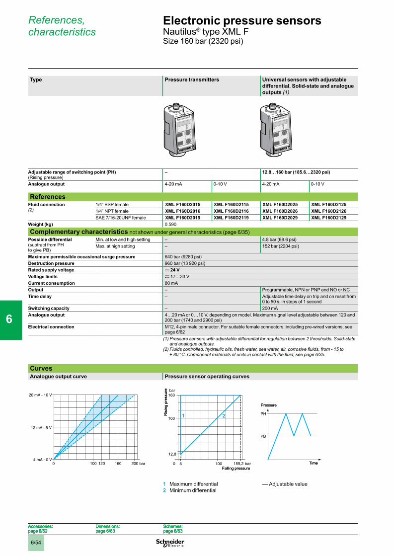
6/54
References, characteristics
Type Pressure transmitters Universal sensors with adjustable differential. Solid-state and analogue outputs (1)
Adjustable range of switching point (PH) (Rising pressure)
– 12.8…160 bar (185.6…2320 psi)
Analogue output 4-20 mA 0-10 V 4-20 mA 0-10 V
ReferencesFluid connection (2)
1/4” BSP female XML F160D2015 XML F160D2115 XML F160D2025 XML F160D21251/4” NPT female XML F160D2016 XML F160D2116 XML F160D2026 XML F160D2126SAE 7/16-20UNF female XML F160D2019 XML F160D2119 XML F160D2029 XML F160D2129
Weight (kg) 0.590
Complementary characteristics not shown under general characteristics (page 6/35)Possible differential (subtract from PH to give PB)
Min. at low and high setting – 4.8 bar (69.6 psi)Max. at high setting – 152 bar (2204 psi)
Maximum permissible occasional surge pressure 640 bar (9280 psi)Destruction pressure 960 bar (13 920 psi)Rated supply voltage c 24 VVoltage limits c 17…33 VCurrent consumption 80 mAOutput – Programmable, NPN or PNP and NO or NCTime delay – Adjustable time delay on trip and on reset from
0 to 50 s, in steps of 1 secondSwitching capacity – 200 mAAnalogue output 4…20 mA or 0…10 V, depending on model. Maximum signal level adjustable between 120 and
200 bar (1740 and 2900 psi)Electrical connection M12, 4-pin male connector. For suitable female connectors, including pre-wired versions, see
page 6/62(1) Pressure sensors with adjustable differential for regulation between 2 thresholds. Solid-state
and analogue outputs.(2)Fluidscontrolled:hydraulicoils,freshwater,seawater,air,corrosivefluids,from-15to
+80°C.Componentmaterialsofunitsincontactwiththefluid,seepage6/35.
CurvesAnalogue output curve Pressure sensor operating curves
1 Maximum differential2 Minimum differential
–– Adjustable value
160100 bar4 mA - 0 V
20 mA - 10 V
12 mA - 5 V
0 120 200160100 bar4 mA - 0 V
20 mA - 10 V
12 mA - 5 V
0 120 200 155,2
160
12,8
8 bar
100
bar
0 100
21Ris
ing
pres
sure
Falling pressure155,2
160
12,8
8 bar
100
bar
0 100
21Ris
ing
pres
sure
Falling pressure
PH
PB
Pressure
Time
PH
PB
Pressure
Time
Accessories:page 6/62
Dimensions:page 6/63
Schemes:page 6/63
Accessories:page 6/62
Dimensions:page 6/63
Schemes:page 6/63
Accessories:page 6/62
Dimensions:page 6/63
Schemes:page 6/63
Accessories:page 6/62
Dimensions:page 6/63
Schemes:page 6/63
Electronic pressure sensors 0 Nautilus® type XML FSize 160 bar (2320 psi)
1
2
3
4
5
6
7
8
9
10

6/55
References, characteristics (continued)
Type Pressure switches with adjustable differential and relay output (1)
Dual stage adjustable pressure switches with solid-state outputs (2)
Adjustable range of switching point(s) (PH or PH1 and PH2) (Rising pressure)
12.8…160 bar (185.6…2320 psi)
ReferencesFluid connection (3)
1/4” BSP female XML F160E2045 XML F160D20351/4” NPT female XML F160E2046 XML F160D2036SAE 7/16-20UNF female XML F160E2049 XML F160D2039
Weight (kg) 0.700 0.590
Complementary characteristics not shown under general characteristics (page 6/35)Possible differential (subtract from:- PH to give PB- PH1 & PH2 to give PB1 & PB2)
Min. at low and high setting 4.8 bar (69.6 psi) For each stage: Max. at high setting 152 bar (2204 psi) min. at low and high setting: 4.8 bar (69.6 psi)
max. at high setting: 152 bar (2204 psi)
Maximum permissible accidental pressure 640 bar (9280 psi)Destruction pressure 960 bar (13 920 psi)Rated supply voltage a 120 V c 24 VVoltage limits a 102…132 V c 17…33 VCurrent consumption 32 mA 80 mAOutput Relay Programmable, NPN or PNP and NO or NCTime delay Adjustable time delay on trip and on reset from 0 to 50 s, in steps of 1 secondSwitching capacity 2.5 A, AC-15, C300 (120 V - 1.5 A) 200 mAElectrical connection SAE 7/8-16UN, 5-pin male connector. For
suitable female pre-wired connectors, see page 6/62.
M12, 4-pin male connector. For suitable female connectors, including pre-wired versions, see page 6/62
(1) Pressure switches with adjustable differential for regulation between 2 thresholds. Relay output.
(2) Pressure switches with 2 adjustable stages and adjustable differential for each threshold. Solid-state outputs.
(3)Fluidscontrolled:hydraulicoils,freshwater,seawater,air,corrosivefluids,from-15to +80°C.Componentmaterialsofunitsincontactwiththefluid,seepage6/35.
Pressure switch operating curves(Curve for each stage for dual stage pressure switches) Pressure switches with relay output Dual stage pressure switches
1 Maximum differential2 Minimum differential
–– Adjustable value –– Adjustable value
155,2
160
12,8
8 bar
100
bar
0 100
21Ris
ing
pres
sure
Falling pressure155,2
160
12,8
8 bar
100
bar
0 100
21Ris
ing
pres
sure
Falling pressure
PH
PB
Pressure
Time
PH
PB
Pressure
Time
PH2
PH1
PB1
PB2
Pressure
Time
PH2
PH1
PB1
PB2
Pressure
Time
Accessories:page 6/62
Dimensions:page 6/63
Schemes:page 6/63
Accessories:page 6/62
Dimensions:page 6/63
Schemes:page 6/63
Accessories:page 6/62
Dimensions:page 6/63
Schemes:page 6/63
Accessories:page 6/62
Dimensions:page 6/63
Schemes:page 6/63
Electronic pressure sensors 0 Nautilus® type XML FSize 160 bar (2320 psi)
1
2
3
4
5
6
7
8
9
10
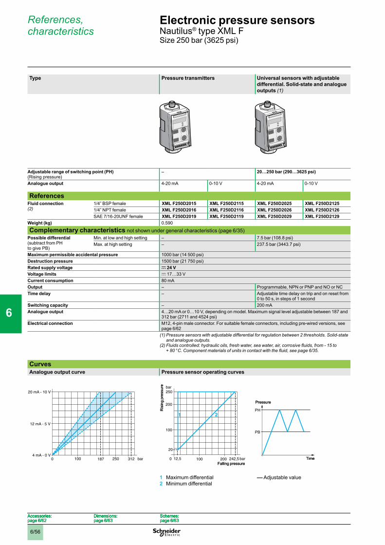
6/56
References, characteristics
Type Pressure transmitters Universal sensors with adjustable differential. Solid-state and analogue outputs (1)
Adjustable range of switching point (PH) (Rising pressure)
– 20…250 bar (290…3625 psi)
Analogue output 4-20 mA 0-10 V 4-20 mA 0-10 V
ReferencesFluid connection (2)
1/4” BSP female XML F250D2015 XML F250D2115 XML F250D2025 XML F250D21251/4” NPT female XML F250D2016 XML F250D2116 XML F250D2026 XML F250D2126SAE 7/16-20UNF female XML F250D2019 XML F250D2119 XML F250D2029 XML F250D2129
Weight (kg) 0.590
Complementary characteristics not shown under general characteristics (page 6/35)Possible differential (subtract from PH to give PB)
Min. at low and high setting – 7.5 bar (108.8 psi)Max. at high setting – 237.5 bar (3443.7 psi)
Maximum permissible accidental pressure 1000 bar (14 500 psi)Destruction pressure 1500 bar (21 750 psi)Rated supply voltage c 24 VVoltage limits c 17…33 VCurrent consumption 80 mAOutput – Programmable, NPN or PNP and NO or NCTime delay – Adjustable time delay on trip and on reset from
0 to 50 s, in steps of 1 secondSwitching capacity – 200 mAAnalogue output 4…20 mA or 0…10 V, depending on model. Maximum signal level adjustable between 187 and
312 bar (2711 and 4524 psi)Electrical connection M12, 4-pin male connector. For suitable female connectors, including pre-wired versions, see
page 6/62(1) Pressure sensors with adjustable differential for regulation between 2 thresholds. Solid-state
and analogue outputs.(2)Fluidscontrolled:hydraulicoils,freshwater,seawater,air,corrosivefluids,from-15to
+80°C.Componentmaterialsofunitsincontactwiththefluid,seepage6/35.
CurvesAnalogue output curve Pressure sensor operating curves
1 Maximum differential2 Minimum differential
–– Adjustable value
100 187 bar4 mA - 0 V
312
20 mA - 10 V
12 mA - 5 V
0 250100 187 bar4 mA - 0 V
312
20 mA - 10 V
12 mA - 5 V
0 250
250
20
12,5 242,5 bar
100
bar
0 100
21
200
200Falling pressure
Ris
ing
pres
sure
250
20
12,5 242,5 bar
100
bar
0 100
21
200
200Falling pressure
Ris
ing
pres
sure
PH
PB
Pressure
Time
PH
PB
Pressure
Time
Accessories:page 6/62
Dimensions:page 6/63
Schemes:page 6/63
Accessories:page 6/62
Dimensions:page 6/63
Schemes:page 6/63
Accessories:page 6/62
Dimensions:page 6/63
Schemes:page 6/63
Accessories:page 6/62
Dimensions:page 6/63
Schemes:page 6/63
Electronic pressure sensors 0 Nautilus® type XML FSize 250 bar (3625 psi)
1
2
3
4
5
6
7
8
9
10

6/57
References, characteristics (continued)
Type Pressure switches with adjustable differential and relay output (1)
Dual stage adjustable pressure switches with solid-state outputs (2)
Adjustable range of switching point(s) (PH or PH1 and PH2) (Rising pressure)
20…250 bar (290…3625 psi)
ReferencesFluid connection (3)
1/4” BSP female XML F250E2045 XML F250D20351/4” NPT female XML F250E2046 XML F250D2036SAE 7/16-20UNF female XML F250E2049 XML F250D2039
Weight (kg) 0.700 0.590
Complementary characteristics not shown under general characteristics (page 6/35)Possible differential (subtract from:- PH to give PB- PH1 & PH2 to give PB1 & PB2)
Min. at low and high setting 7.5 bar (108.8 psi) For each stage: Max. at high setting 237.5 bar (3443.7 psi) Min. at low and high setting: 7.5 bar (108.8 psi)
Max. at high setting: 237.5 bar (3443.7 psi)
Maximum permissible accidental pressure 1000 bar (14 500 psi)Destruction pressure 1500 bar (21 750 psi)Rated supply voltage a 120 V c 24 VVoltage limits a 102…132 V c 17…33 VCurrent consumption 32 mA 80 mAOutput Relay Programmable, NPN or PNP and NO or NCTime delay Adjustable time delay on trip and on reset from 0 to 50 s, in steps of 1 secondSwitching capacity 2.5 A, AC-15, C300 (120 V - 1.5 A) 200 mAElectrical connection SAE 7/8-16UN, 5-pin male connector. For
suitable female pre-wired connectors, see page 6/62.
M12, 4-pin male connector. For suitable female connectors, including pre-wired versions, see page 6/62
(1) Pressure switches with adjustable differential for regulation between 2 thresholds. Relay output.
(2) Pressure switches with 2 adjustable stages and adjustable differential for each threshold. Solid-state outputs.
(3)Fluidscontrolled:hydraulicoils,freshwater,seawater,air,corrosivefluids,from-15to +80°C.Componentmaterialsofunitsincontactwiththefluid,seepage6/35.
Pressure switch operating curves(Curve for each stage for dual stage pressure switches) Pressure switches with relay output Dual stage pressure switches
1 Maximum differential2 Minimum differential
–– Adjustable value –– Adjustable value
250
20
12,5 242,5 bar
100
bar
0 100
21
200
200Falling pressure
Ris
ing
pres
sure
250
20
12,5 242,5 bar
100
bar
0 100
21
200
200Falling pressure
Ris
ing
pres
sure
PH
PB
Pressure
Time
PH
PB
Pressure
Time
PH2
PH1
PB1
PB2
Pressure
Time
PH2
PH1
PB1
PB2
Pressure
Time
Accessories:page 6/62
Dimensions:page 6/63
Schemes:page 6/63
Accessories:page 6/62
Dimensions:page 6/63
Schemes:page 6/63
Accessories:page 6/62
Dimensions:page 6/63
Schemes:page 6/63
Accessories:page 6/62
Dimensions:page 6/63
Schemes:page 6/63
Electronic pressure sensors 0 Nautilus® type XML FSize 250 bar (3625 psi)
1
2
3
4
5
6
7
8
9
10
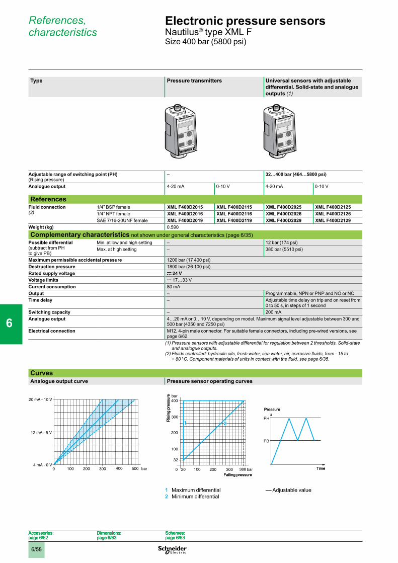
6/58
References, characteristics
Type Pressure transmitters Universal sensors with adjustable differential. Solid-state and analogue outputs (1)
Adjustable range of switching point (PH) (Rising pressure)
– 32…400 bar (464…5800 psi)
Analogue output 4-20 mA 0-10 V 4-20 mA 0-10 V
ReferencesFluid connection (2)
1/4” BSP female XML F400D2015 XML F400D2115 XML F400D2025 XML F400D21251/4” NPT female XML F400D2016 XML F400D2116 XML F400D2026 XML F400D2126SAE 7/16-20UNF female XML F400D2019 XML F400D2119 XML F400D2029 XML F400D2129
Weight (kg) 0.590
Complementary characteristics not shown under general characteristics (page 6/35)Possible differential (subtract from PH to give PB)
Min. at low and high setting – 12 bar (174 psi)Max. at high setting – 380 bar (5510 psi)
Maximum permissible accidental pressure 1200 bar (17 400 psi)Destruction pressure 1800 bar (26 100 psi)Rated supply voltage c 24 VVoltage limits c 17…33 VCurrent consumption 80 mAOutput – Programmable, NPN or PNP and NO or NCTime delay – Adjustable time delay on trip and on reset from
0 to 50 s, in steps of 1 secondSwitching capacity – 200 mAAnalogue output 4…20 mA or 0…10 V, depending on model. Maximum signal level adjustable between 300 and
500 bar (4350 and 7250 psi)Electrical connection M12, 4-pin male connector. For suitable female connectors, including pre-wired versions, see
page 6/62(1) Pressure sensors with adjustable differential for regulation between 2 thresholds. Solid-state
and analogue outputs.(2)Fluidscontrolled:hydraulicoils,freshwater,seawater,air,corrosivefluids,from-15to
+80°C.Componentmaterialsofunitsincontactwiththefluid,seepage6/35.
CurvesAnalogue output curve Pressure sensor operating curves
1 Maximum differential2 Minimum differential
–– Adjustable value
100 200 300 bar4 mA - 0 V
400
20 mA - 10 V
12 mA - 5 V
0 500100 200 300 bar4 mA - 0 V
400
20 mA - 10 V
12 mA - 5 V
0 500
100
300
100
400
32
20 388 bar
200
200
bar
0
1
300
2
Falling pressure
Ris
ing
pres
sure
100
300
100
400
32
20 388 bar
200
200
bar
0
1
300
2
Falling pressure
Ris
ing
pres
sure
PH
PB
Pressure
Time
PH
PB
Pressure
Time
Accessories:page 6/62
Dimensions:page 6/63
Schemes:page 6/63
Accessories:page 6/62
Dimensions:page 6/63
Schemes:page 6/63
Accessories:page 6/62
Dimensions:page 6/63
Schemes:page 6/63
Accessories:page 6/62
Dimensions:page 6/63
Schemes:page 6/63
Electronic pressure sensors 0 Nautilus® type XML FSize 400 bar (5800 psi)
1
2
3
4
5
6
7
8
9
10

6/59
References, characteristics (continued)
Type Pressure switches with adjustable differential and relay output (1)
Dual stage adjustable pressure switches with solid-state outputs (2)
Adjustable range of switching point(s) (PH or PH1 and PH2) (Rising pressure)
32…400 bar (464…5800 psi)
ReferencesFluid connection (3)
1/4” BSP female XML F400E2045 XML F400D20351/4” NPT female XML F400E2046 XML F400D2036SAE 7/16-20UNF female XML F400E2049 XML F400D2039
Weight (kg) 0.700 0.590
Complementary characteristics not shown under general characteristics (page 6/35)Possible differential (subtract from:- PH to give PB- PH1 & PH2 to give PB1 & PB2)
Min. at low and high setting 12 bar (174 psi) For each stage:Max. at high setting 380 bar (5510 psi) min. at low and high setting: 12 bar (174 psi)
max. at high setting: 380 bar (5510 psi)
Maximum permissible accidental pressure 1200 bar (17,400 psi)Destruction pressure 1800 bar (26 100 psi)Rated supply voltage a 120 V c 24 VVoltage limits a 102…132 V c 17…33 VCurrent consumption 32 mA 80 mAOutput Relay Programmable, NPN or PNP and NO or NCTime delay Adjustable time delay on trip and on reset from 0 to 50 s, in steps of 1 secondSwitching capacity 2.5 A, AC-15, C300 (120 V - 1.5 A) 200 mAElectrical connection SAE 7/8-16UN, 5-pin male connector. For
suitable female pre-wired connectors, see page 6/62.
M12, 4-pin male connector. For suitable female connectors, including pre-wired versions, see page 6/62
(1) Pressure switches with adjustable differential for regulation between 2 thresholds. Relay output.
(2) Pressure switches with 2 adjustable stages and adjustable differential for each threshold. Solid-state outputs.
(3)Fluidscontrolled:hydraulicoils,freshwater,seawater,air,corrosivefluids,from-15to +80°C.Componentmaterialsofunitsincontactwiththefluid,seepage6/35.
Pressure switch operating curves(Curve for each stage for dual stage pressure switches) Pressure switches with relay output Dual stage pressure switches
1 Maximum differential2 Minimum differential
–– Adjustable value –– Adjustable value
100
300
100
400
32
20 388 bar
200
200
bar
0
1
300
2
Falling pressure
Ris
ing
pres
sure
100
300
100
400
32
20 388 bar
200
200
bar
0
1
300
2
Falling pressure
Ris
ing
pres
sure
PH
PB
Pressure
Time
PH
PB
Pressure
Time
PH2
PH1
PB1
PB2
Pressure
Time
PH2
PH1
PB1
PB2
Pressure
Time
Accessories:page 6/62
Dimensions:page 6/63
Schemes:page 6/63
Accessories:page 6/62
Dimensions:page 6/63
Schemes:page 6/63
Accessories:page 6/62
Dimensions:page 6/63
Schemes:page 6/63
Accessories:page 6/62
Dimensions:page 6/63
Schemes:page 6/63
Electronic pressure sensors 0 Nautilus® type XML FSize 400 bar (5800 psi)
1
2
3
4
5
6
7
8
9
10
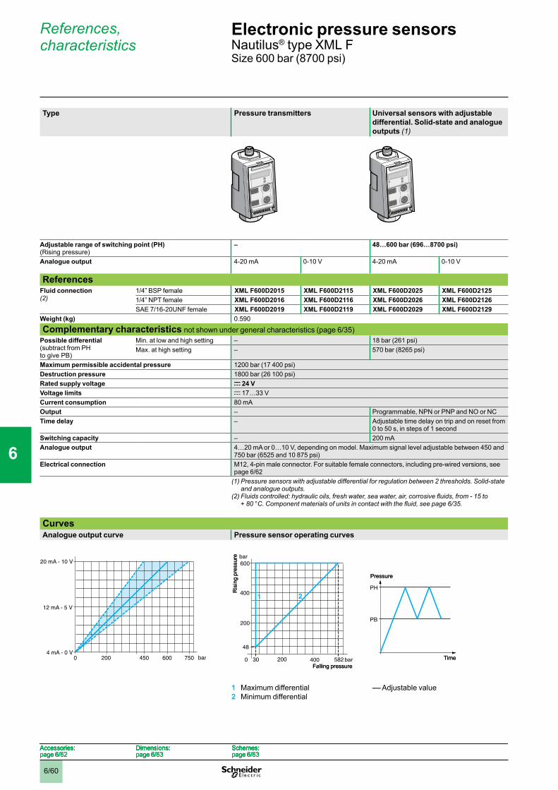
6/60
References, characteristics
Type Pressure transmitters Universal sensors with adjustable differential. Solid-state and analogue outputs (1)
Adjustable range of switching point (PH) (Rising pressure)
– 48…600 bar (696…8700 psi)
Analogue output 4-20 mA 0-10 V 4-20 mA 0-10 V
ReferencesFluid connection (2)
1/4” BSP female XML F600D2015 XML F600D2115 XML F600D2025 XML F600D21251/4” NPT female XML F600D2016 XML F600D2116 XML F600D2026 XML F600D2126SAE 7/16-20UNF female XML F600D2019 XML F600D2119 XML F600D2029 XML F600D2129
Weight (kg) 0.590
Complementary characteristics not shown under general characteristics (page 6/35)Possible differential (subtract from PH to give PB)
Min. at low and high setting – 18 bar (261 psi)Max. at high setting – 570 bar (8265 psi)
Maximum permissible accidental pressure 1200 bar (17 400 psi)Destruction pressure 1800 bar (26 100 psi)Rated supply voltage c 24 VVoltage limits c 17…33 VCurrent consumption 80 mAOutput – Programmable, NPN or PNP and NO or NCTime delay – Adjustable time delay on trip and on reset from
0 to 50 s, in steps of 1 secondSwitching capacity – 200 mAAnalogue output 4…20 mA or 0…10 V, depending on model. Maximum signal level adjustable between 450 and
750 bar (6525 and 10 875 psi)Electrical connection M12, 4-pin male connector. For suitable female connectors, including pre-wired versions, see
page 6/62(1) Pressure sensors with adjustable differential for regulation between 2 thresholds. Solid-state
and analogue outputs.(2)Fluidscontrolled:hydraulicoils,freshwater,seawater,air,corrosivefluids,from-15to
+80°C.Componentmaterialsofunitsincontactwiththefluid,seepage6/35.
CurvesAnalogue output curve Pressure sensor operating curves
1 Maximum differential2 Minimum differential
–– Adjustable value
200 450 bar4 mA - 0 V
750
20 mA - 10 V
12 mA - 5 V
0 600200 450 bar4 mA - 0 V
750
20 mA - 10 V
12 mA - 5 V
0 600
600
48
30 582 bar
200
bar
0 400
21400
200Falling pressure
Ris
ing
pres
sure
600
48
30 582 bar
200
bar
0 400
21400
200Falling pressure
Ris
ing
pres
sure
PH
PB
Pressure
Time
PH
PB
Pressure
Time
Accessories:page 6/62
Dimensions:page 6/63
Schemes:page 6/63
Accessories:page 6/62
Dimensions:page 6/63
Schemes:page 6/63
Accessories:page 6/62
Dimensions:page 6/63
Schemes:page 6/63
Accessories:page 6/62
Dimensions:page 6/63
Schemes:page 6/63
Electronic pressure sensors 0 Nautilus® type XML FSize 600 bar (8700 psi)
1
2
3
4
5
6
7
8
9
10
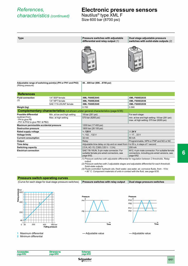
6/61
References, characteristics (continued)
Type Pressure switches with adjustable differential and relay output (1)
Dual stage adjustable pressure switches with solid-state outputs (2)
Adjustable range of switching point(s) (PH or PH1 and PH2) (Rising pressure)
48…600 bar (696…8700 psi)
ReferencesFluid connection (3)
1/4” BSP female XML F600E2045 XML F600D20351/4” NPT female XML F600E2046 XML F600D2036SAE 7/16-20UNF female XML F600E2049 XML F600D2039
Weight (kg) 0.700 0.590
Complementary characteristics not shown under general characteristics (page 6/35)Possible differential (subtract from:- PH to give PB- PH1 & PH2 to give PB1 & PB2)
Min. at low and high setting 18 bar (261 psi) For each stage:Max. at high setting 570 bar (8265 psi) min. at low and high setting: 18 bar (261 psi)
max. at high setting: 570 bar (8265 psi)
Maximum permissible accidental pressure 1200 bar (17 400 psi)Destruction pressure 1800 bar (26 100 psi)Rated supply voltage a 120 V c 24 VVoltage limits a 102…132 V c 17…33 VCurrent consumption 32 mA 80 mAOutput Relay Programmable, NPN or PNP and NO or NCTime delay Adjustable time delay on trip and on reset from 0 to 50 s, in steps of 1 secondSwitching capacity 2.5 A, AC-15, C300 (120 V - 1.5 A) 200 mAElectrical connection SAE 7/8-16UN, 5-pin male connector. For
suitable female pre-wired connectors, see page 6/62.
M12, 4-pin male connector. For suitable female connectors, including pre-wired versions, see page 6/62
(1) Pressure switches with adjustable differential for regulation between 2 thresholds. Relay output.
(2) Pressure switches with 2 adjustable stages and adjustable differential for each threshold. Solid-state outputs.
(3)Fluidscontrolled:hydraulicoils,freshwater,seawater,air,corrosivefluids,from-15to +80°C.Componentmaterialsofunitsincontactwiththefluid,seepage6/35.
Pressure switch operating curves(Curve for each stage for dual stage pressure switches) Pressure switches with relay output Dual stage pressure switches
1 Maximum differential2 Minimum differential
–– Adjustable value –– Adjustable value
600
48
30 582 bar
200
bar
0 400
21400
200Falling pressure
Ris
ing
pres
sure
600
48
30 582 bar
200
bar
0 400
21400
200Falling pressure
Ris
ing
pres
sure
PH
PB
Pressure
Time
PH
PB
Pressure
Time
PH2
PH1
PB1
PB2
Pressure
Time
PH2
PH1
PB1
PB2
Pressure
Time
Accessories:page 6/62
Dimensions:page 6/63
Schemes:page 6/63
Accessories:page 6/62
Dimensions:page 6/63
Schemes:page 6/63
Accessories:page 6/62
Dimensions:page 6/63
Schemes:page 6/63
Accessories:page 6/62
Dimensions:page 6/63
Schemes:page 6/63
Electronic pressure sensors 0 Nautilus® type XML FSize 600 bar (8700 psi)
1
2
3
4
5
6
7
8
9
10
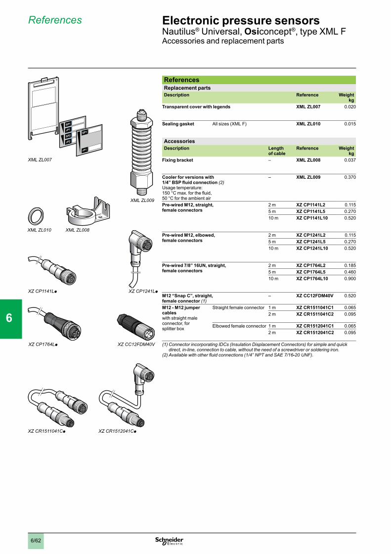
6/62
XML ZL007
XML ZL010 XML ZL008
XML ZL009
XZ CP1141Lp XZ CP1241Lp
XZ CP1764Lp XZCC12FDM40V
XZ CR1511041Cp XZ CR1512041Cp
References
ReferencesReplacement partsDescription Reference Weight
kgTransparent cover with legends XML ZL007 0.020
Sealing gasket All sizes (XML F) XML ZL010 0.015
AccessoriesDescription Length
of cable Reference Weight
kgFixing bracket – XML ZL008 0.037
Cooler for versions with 1/4” BSP fluid connection (2)Usage temperature: 150 °C max. for the fluid, 50 °C for the ambient air
– XML ZL009 0.370
Pre-wired M12, straight, female connectors
2 m XZ CP1141L2 0.1155 m XZ CP1141L5 0.27010 m XZ CP1141L10 0.520
Pre-wired M12, elbowed, female connectors
2 m XZ CP1241L2 0.1155 m XZ CP1241L5 0.27010 m XZ CP1241L10 0.520
Pre-wired 7/8” 16UN, straight, female connectors
2 m XZ CP1764L2 0.1855 m XZ CP1764L5 0.46010 m XZ CP1764L10 0.900
M12 “Snap C”, straight, female connector (1)
– XZ CC12FDM40V 0.520
M12 - M12 jumper cableswith straight male connector, for splitter box
Straight female connector 1 m XZ CR1511041C1 0.0652 m XZ CR1511041C2 0.095
Elbowed female connector 1 m XZ CR1512041C1 0.0652 m XZ CR1512041C2 0.095
(1)ConnectorincorporatingIDCs(InsulationDisplacementConnectors)forsimpleandquickdirect, in-line, connection to cable, without the need of a screwdriver or soldering iron.
(2)Availablewithotherfluidconnections(1/4”NPTandSAE7/16-20UNF).
Electronic pressure sensors 0 Nautilus® Universal, Osiconcept®, type XML FAccessories and replacement parts
1
2
3
4
5
6
7
8
9
10
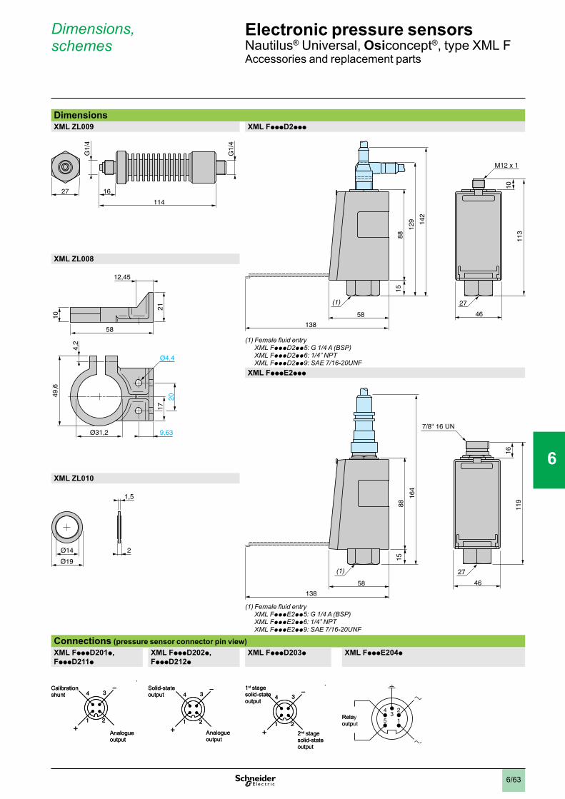
6/63
Dimensions, schemes
DimensionsXML ZL009 XML FpppD2ppp
(1)Femalefluidentry XML FpppD2pp5:G1/4A(BSP) XML FpppD2pp6:1/4”NPT XML FpppD2pp9:SAE7/16-20UNF
XML ZL008
XML FpppE2ppp
(1)Femalefluidentry XML FpppE2pp5:G1/4A(BSP) XML FpppE2pp6:1/4”NPT XML FpppE2pp9:SAE7/16-20UNF
XML ZL010
Connections (pressure sensor connector pin view)XML FpppD201p, FpppD211p
XML FpppD202p, FpppD212p
XML FpppD203p XML FpppE204p
G1/
4
G1/
4
1627
114
G1/
4
G1/
4
1627
114
138
8815
129 14
2
113
10
58 46
27(1)
M12 x 1
138
8815
129 14
2
113
10
58 46
27(1)
M12 x 1
Ø4,4
58
17
49,6
20
4,2
10
12,45
Ø31,2
21
9,63
Ø4,4
58
17
49,6
20
4,2
10
12,45
Ø31,2
21
9,63
138
8815
164
119
16
58 46
27(1)
7/8" 16 UN
138
8815
164
119
16
58 46
27(1)
7/8" 16 UN
Ø14 2
1,5
Ø19
Ø14 2
1,5
Ø19
1 2
4 3
+
–Calibration shunt
Analogue output
1 2
4 3
+
–Calibration shunt
Analogue output
1 2
4 3
+
–Solid-state output
Analogue output
1 2
4 3
+
–Solid-state output
Analogue output
1 2
4 3
+
–1st stage solid-state output
2nd stage solid-state output
1 2
4 3
+
–1st stage solid-state output
2nd stage solid-state output
43
2
5 1Relay output
43
2
5 1Relay output
Electronic pressure sensors 0 Nautilus® Universal, Osiconcept®, type XML FAccessories and replacement parts
1
2
3
4
5
6
7
8
9
10

6/64
General
FunctionsPressure transmittersThe function of pressure transmitters is the control and measurement of pressure or vacuum levels in hydraulic or pneumatic systems. They transform the pressure into an electrical signal which is proportional to the pressure measured.Their high precision makes them suitable for all industrial applications requiring pressure/vacuum display, control or regulation.Being very robust, they are equally suitable for applications involving high operating rates.Pressure and vacuum switchesThe function of electronic pressure and vacuum switches is the control or regulation of pressure or vacuum levels in hydraulic or pneumatic systems. They transform the pressure change into a digital output signal when the preset pressure or vacuum points are reached. The very wide adjustment range for the setting points characterise these electronic switches.Their robustness, together with their excellent adherence to the set values over a period of time, make them ideal for applications involving high operating rates.In addition, the high repeat accuracy and fast response time of these sensors make them equally suitable for applications requiring accurate pressure regulation and monitoring.Universal sensorsUniversal sensors are electronic pressure and vacuum switches which include an analogue output, identical to that of the pressure transmitters.Operating principlePressure transmittersThe electrical signal from the pressure transmitter (signal proportional to the pressure being monitored) is amplified, calibrated and output as a standard 4 to 20 mA or 0 to 10 V (depending on model) analogue signal.
Pressure and vacuum switchesDesigned for regulation between 2 thresholds (adjustable differential), these switches have both a high point setting (PH) and a low point setting (PB). Both of these points can be independently adjusted.The difference (differential) between the two setting points can be little or considerable, thus enabling small or large differentials to be set.Being electronic, the switches have no mechanical moving parts.Operating principle with solid-state NC outputs
Pressure switches with digital output
Vacuum switches with digital output
–– Adjustable valuePH = high pointPB = low point
1 Output on2 Output off
1 Output on2 Output off
Dual stage pressure switches–– Adjustable valuePH1 = high point 1st stagePB1 = low point 1st stagePH2 = high point 2nd stagePB2 = low point 2nd stage1 Output 1st stage on2 Output 1st stage off3 Output 2nd stage on4 Output 2nd stage off
Signal
PressureOperating range
4…20 mA or 0…10 V
Signal
PressureOperating range
4…20 mA or 0…10 V
1 2 1 2
Pressure
Time
PH
PB
Adjustable differential
1 2 1 2
Pressure
Time
PH
PB
Adjustable differential
2 1 2 1
Time
Vacuum
PH
PB
Adjustable differential
2 1 2 1
Time
Vacuum
PH
PB
Adjustable differential
1 1
3
PH2
PH1
PB2
PB1
2 24 3 4
Time
Adjustable differential
Adjustable differential
Pressure
1 1
3
PH2
PH1
PB2
PB1
2 24 3 4
Time
Adjustable differential
Adjustable differential
Pressure
Electronic pressure sensors 0 Nautilus®
For control circuits
1
2
3
4
5
6
7
8
9
10

6/65
General(continued)
TerminologyMeasuring rangeThe measuring range (M.R.) of a pressure sensor corresponds to the difference between the upper and lower values measured by the load cell. It is comprised between 0 bar and the pressure corresponding to the size of the sensor.
Operating rangeThe operating range of a pressure transmitter corresponds to its measuring range. Within this range, its analogue output signal varies between 4 and 20 mA or 0 and 10 V and is proportional to the measured pressure.The operating range of a pressure or vacuum switch is the difference between the minimum low point (PB) and the maximum high point (PH) setting values.
PrecisionThis comprises linearity, hysteresis, repeat accuracy and setting tolerances. It is expressed as a % of the measuring range (M.R.) of the load cell (% M.R.).
The linearity is the maximum deviation between the real transmitted curve and the ideal curve.
The hysteresis is the maximum deviation between the rising pressure curve and the falling pressure curve.
The repeat accuracy is the maximum drift encountered at varying pressures under given conditions.
The setting tolerances are the manufacturer’s tolerances regarding the zero point and sensitivity (gradient of output signal curve from pressure transmitter).
Temperature driftThe precision of a pressure sensor is always susceptible to variation due to the operating temperature.
Zero point driftThis is proportional to the temperature and is expressed as % M.R./°C.
Sensitivity driftThis is proportional to the temperature and is expressed as % M.R./°C.
Signal
Pressure
Signal
Pressure
Signal
Pressure
Signal
Pressure
Signal
Pressure
Signal
Pressure
Signal
Pressure
Signal
Pressure
Signal
Pressure
Signal
Pressure
t°t°
Signal
Pressure
t°t°
Signal
Pressure
t°
t°
Signal
Pressure
t°
t°
Signal
Pressure
Electronic pressure sensors 0 Nautilus®
For control circuits
1
2
3
4
5
6
7
8
9
10
6/66
General(continued)
Terminology (continued)Switching point on rising pressure (PH)The upper pressure setting at which the output of the electronic pressure or vacuum switch changes state on rising pressure.
Switching point on falling pressure (PB)The lower pressure setting at which the output of the electronic pressure or vacuum switch changes state on falling pressure.
DifferentialThe difference between the switching point on rising pressure (PH) and the switching point on falling pressure (PB). The low point can be set at the values indicated on the operating curves shown on the product pages.
Repeat accuracyThe variation of the operating point of the pressure or vacuum switch between several successive operations.
SizePressure transmitters and pressure switchesThis is the maximum value of the operating range.Vacuum transmitters and vacuum switchesThis is the minimum value of the operating range.
Maximum permissible accidental pressureThe maximum pressure (excluding pressure surges) that the sensor can occasionally withstand without permanent damage.
Destruction pressureThe pressure value which if exceeded is likely to cause serious damage to the sensor, i.e. leaking, bursting, component failure, etc.
Load resistance of pressure transmittersThe supply voltage and load resistance of a pressure transmitter must be selected according to the formula:
R load = U supply - U supply min. (U supply min. = 11 V for XML E and 17 V for XML F) 0.02 A
Electronic pressure sensors 0 Nautilus®
For control circuits
1
2
3
4
5
6
7
8
9
10

6/67
General(continued)
Features of pressure sensors XML FPressure sensors type XML F (see page 6/34) feature numerous configuration possibilities with regards to the display (response time, choice of bar or psi units of measurement), analogue output signal operation (maximum signal output adjustable between 75% and 125% of the units size), solid-state output operation (PNP or NPN, NO or NC, time delay on opening or on closing, response time) and status signalling (see below).A diagnostic function is incorporated which enables verification, at any time, of the sensors correct operation (see below) and also, to provide information regarding pressure peak values.
Self-test function (calibration shunt)All pressure sensors XML F incorporate a diagnostic function which can be used, at any time, to check the correct operation of the unit. It comprises an internal system which enables automatic monitoring of all the sensor circuits, including the ceramic pressure measuring load cell.For all models, this function is manually activated and the result of the test is indicated on the display (DONE or ERR).For pressure transmitters, this function can also be remotely activated via a digital input connected to a PLC, thus enabling automatic verification without the need of intervention by an operator. In this instance, the self-test also generates an analogue output signal which is equivalent to 50% of the sensors size (12 mA or 5 V) which, in turn, can be verified by the PLC. The unit can be considered as defective if the difference between the signal transmitted and the standard theoretical value is too great.
Operational status signallingPressure and vacuum switches XML F feature status LED indicators for the digital outputs. Indication can be configured for 2 modes:
“hysteresis” mode: indicator illuminated when output activated (output off for NC configuration or output on for NO configuration).
“window” mode: indicator illuminated when the pressure being measured is between the high and low set point values.
-
-
Selection of switch sizeSize selection is made according to the maximum pressure of the system to be controlled.
Adherence to pressureSelect a size whereby the nominal pressure is higher than the maximum pressure of the system to be controlled.
Precision, repeat accuracyThe precision and repeat accuracy are expressed as a percentage of the measuring range and better detection is achieved when the size of the sensor is close to that of the maximum pressure of the system to be controlled. As general rule, avoid working towards the bottom limit of the measuring range.
Minimum differential of a pressure or vacuum switchThe minimum differential for each switch size is 2% for XML E and 3% for XML F of its operating range.
Selection example for a pressure switchMaximum pressure of system = 11 barPH = 7 barPB = 6 bar2 alternative choices:XML p010ppppp (10 bar) orXML p025ppppp (25 bar)Advantages:XML p010ppppp: maximum repeat accuracy and precisionXML p025ppppp: withstand to overpressure.
Electronic pressure sensors 0 Nautilus®
For control circuits
1
2
3
4
5
6
7
8
9
10

6/68
Presentation
Presentation
Pressure and vacuum switches type XML are switches for control circuits.They are used to control the pressure of hydraulic oils, fresh water, sea water, air, steam, corrosive fluids or viscous products, up to 500 bar.
XML A pressure and vacuum switches have a fixed differential and are for detection of a single threshold. They incorporate a 1 C/O single-pole contact.XML B pressure and vacuum switches have an adjustable differential and are for regulation between 2 thresholds. They incorporate a 1 C/O single-pole contact.XML C pressure and vacuum switches have an adjustable differential and are for regulation between 2 thresholds. They incorporate 2 C/O single-pole contacts.XML D pressure and vacuum switches are dual stage switches, each stage with a fixed differential, and are for detection at each threshold. They incorporate 2 C/O single-pole contacts (one per stage).
Setting
When setting pressure and vacuum switches XML, adjust the switching point on rising pressure (PH) first and then the switching point on falling pressure (PB).
Pressure and vacuum switches with fixed differential, type XML A
Switching point on rising pressureThe switching point on rising pressure (PH) is set by adjusting the red screw 1.
Switching point on falling pressureThe switching point on falling pressure (PB) is not adjustable. The difference between the tripping and resetting points of the contact is the natural differential of the switch (contact differential, friction, etc.).
Pressure and vacuum switches with adjustable differential, types XML B and XML C
Switching point on rising pressureThe switching point on rising pressure (PH) is set by adjusting the red screw 1.
Switching point on falling pressureThe switching point on falling pressure (PB) is set by adjusting the green screw 2.
Dual stage pressure and vacuum switches with fixed differential for each threshold, type XML D
Switching point on rising pressure of stage 1 and stage 2The first stage switching point on rising pressure (PH1) is set by adjusting the red screw 1.The second stage switching point on rising pressure (PH2) is set by adjusting the blue screw 2.
Switching point on falling pressureThe switching points on falling pressure (PB1 and PB2) are not adjustable. The difference between the tripping and resetting points of each contact is the natural differential of the switch (contact differential, friction, etc.).
1
1 2
1 2
Electromechanical pressure and vacuum switches 0 Nautilus®
For control circuits, type XML
1
2
3
4
5
6
7
8
9
10
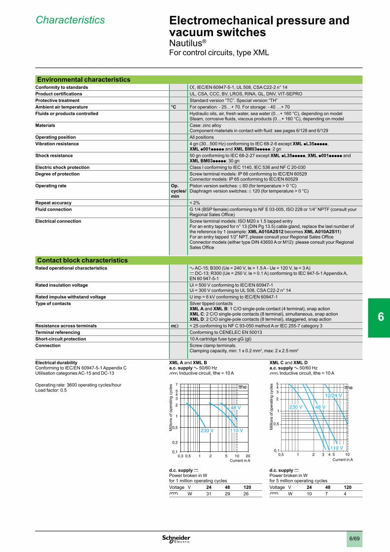
6/69
Characteristics
Environmental characteristicsConformity to standards e, IEC/EN 60947-5-1, UL 508, CSA C22-2 n° 14Product certifications UL, CSA, CCC, BV, LROS, RINA, GL, DNV, VIT-SEPROProtective treatment Standard version “TC”. Special version “TH”Ambient air temperature °C For operation: - 25…+ 70. For storage: - 40 …+ 70Fluids or products controlled Hydraulic oils, air, fresh water, sea water (0…+ 160 °C), depending on model
Steam, corrosive fluids, viscous products (0…+ 160 °C), depending on modelMaterials Case: zinc alloy
Component materials in contact with fluid: see pages 6/128 and 6/129Operating position All positionsVibration resistance 4 gn (30...500 Hz) conforming to IEC 68-2-6 except XML pL35ppppp,
XML p001ppppp and XML BM03ppppp: 2 gnShock resistance 50 gn conforming to IEC 68-2-27 except XML pL35ppppp, XML p001ppppp and
XML BM03ppppp: 30 gnElectric shock protection Class I conforming to IEC 1140, IEC 536 and NF C 20-030Degree of protection Screw terminal models: IP 66 conforming to IEC/EN 60529
Connector models: IP 65 conforming to IEC/EN 60529Operating rate Op.
cycles/min
Piston version switches: ≤ 60 (for temperature > 0 °C)Diaphragm version switches: ≤ 120 (for temperature > 0 °C)
Repeat accuracy < 2%Fluid connection G 1/4 (BSP female) conforming to NF E 03-005, ISO 228 or 1/4” NPTF (consult your
Regional Sales Office)Electrical connection Screw terminal models: ISO M20 x 1.5 tapped entry
For an entry tapped for n° 13 (DIN Pg 13.5) cable gland, replace the last number of the reference by 1 (example: XML A010A2S12 becomes XML A010A2S11)For an entry tapped 1/2” NPT, please consult your Regional Sales OfficeConnector models (either type DIN 43650 A or M12): please consult your Regional Sales Office
Contact block characteristicsRated operational characteristics a AC-15; B300 (Ue = 240 V, Ie = 1.5 A - Ue = 120 V, Ie = 3 A)
c DC-13; R300 (Ue = 250 V, Ie = 0.1 A) conforming to IEC 947-5-1 Appendix A, EN 60 947-5-1
Rated insulation voltage Ui = 500 V conforming to IEC/EN 60947-1Ui = 300 V conforming to UL 508, CSA C22-2 n° 14
Rated impulse withstand voltage U imp = 6 kV conforming to IEC/EN 60947-1Type of contacts Silver tipped contacts
XML A and XML B: 1 C/O single-pole contact (4 terminal), snap action XML C: 2 C/O single-pole contacts (8 terminal), simultaneous, snap actionXML D: 2 C/O single-pole contacts (8 terminal), staggered, snap action
Resistance across terminals mW < 25 conforming to NF C 93-050 method A or IEC 255-7 category 3Terminal referencing Conforming to CENELEC EN 50013Short-circuit protection 10 A cartridge fuse type gG (gl)Connection Screw clamp terminals.
Clamping capacity, min: 1 x 0.2 mm2, max: 2 x 2.5 mm2
Electrical durabilityConforming to IEC/EN 60947-5-1 Appendix CUtilisation categories AC-15 and DC-13
XML A and XML Ba.c. supply a 50/60 Hzo Inductive circuit, lthe = 10 A
XML C and XML Da.c. supply a 50/60 Hzo Inductive circuit, lthe = 10 A
Operating rate: 3600 operating cycles/hourLoad factor: 0.5
d.c. supply cPower broken in W for 1 million operating cycles
d.c. supply cPower broken in W for 5 million operating cycles
Voltage V 24 48 120 Voltage V 24 48 120o W 31 29 26 o W 10 7 4
0,3 0,5 1 2 5 10 200,1
0,2
0,5
1
2
345
7
110 V
48 V
230 V
Ithe
Mill
ions
of o
pera
ting
cycl
es
Current in A0,5 1 2 5 10
0,1
0,5
1
5
2
34
230 V 48 V
Ithe
12/24 V
3 4
110 V
Mill
ions
of o
pera
ting
cycl
es
Current in A
Electromechanical pressure and vacuum switches 0 Nautilus®
For control circuits, type XML
1
2
3
4
5
6
7
8
9
10
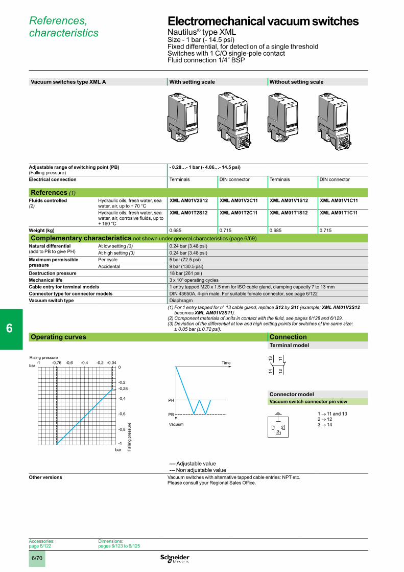
6/70
References, characteristics
Vacuum switches type XML A With setting scale Without setting scale
Adjustable range of switching point (PB) (Falling pressure)
- 0.28…- 1 bar (- 4.06…- 14.5 psi)
Electrical connection Terminals DIN connector Terminals DIN connector
References (1)Fluids controlled (2)
Hydraulic oils, fresh water, sea water, air, up to + 70 °C
XML AM01V2S12 XML AM01V2C11 XML AM01V1S12 XML AM01V1C11
Hydraulic oils, fresh water, sea water, air, corrosive fluids, up to + 160 °C
XML AM01T2S12 XML AM01T2C11 XML AM01T1S12 XML AM01T1C11
Weight (kg) 0.685 0.715 0.685 0.715
Complementary characteristics not shown under general characteristics (page 6/69)Natural differential (add to PB to give PH)
At low setting (3) 0.24 bar (3.48 psi)At high setting (3) 0.24 bar (3.48 psi)
Maximum permissible pressure
Per cycle 5 bar (72.5 psi)Accidental 9 bar (130.5 psi)
Destruction pressure 18 bar (261 psi)Mechanical life 3 x 10⁶ operating cyclesCable entry for terminal models 1 entry tapped M20 x 1.5 mm for ISO cable gland, clamping capacity 7 to 13 mmConnector type for connector models DIN 43650A, 4-pin male. For suitable female connector, see page 6/122Vacuum switch type Diaphragm
(1) For 1 entry tapped for n° 13 cable gland, replace S12 by S11 (example: XML AM01V2S12 becomes XML AM01V2S11).
(2)Componentmaterialsofunitsincontactwiththefluid,seepages6/128 and 6/129.(3)Deviationofthedifferentialatlowandhighsettingpointsforswitchesofthesamesize:
± 0.05 bar (± 0.72 psi).
Operating curves ConnectionTerminal model
Connector modelVacuum switch connector pin view
1 → 11 and 132 → 123 → 14
–– Adjustable value--- Non adjustable value
Other versions Vacuum switches with alternative tapped cable entries: NPT etc. Please consult your Regional Sales Office.
bar
bar 0-0,04-0,2-0,4-0,6-0,76
-0,2
-0,28
-0,4
-0,6
-0,8
-1
-1Rising pressure
Falli
ng p
ress
ure
PH
PB
Time
Vacuum
1314 12
11
321
Accessories:page 6/122
Dimensions:pages 6/123 to 6/125
Electromechanical vacuum switches 0 Nautilus® type XMLSize - 1 bar (- 14.5 psi)Fixed differential, for detection of a single thresholdSwitches with 1 C/O single-pole contactFluid connection 1/4” BSP
1
2
3
4
5
6
7
8
9
10
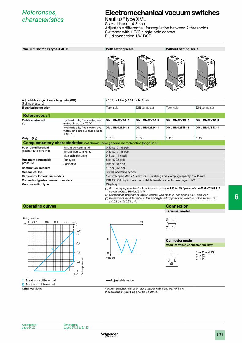
6/71
References, characteristics
Vacuum switches type XML B With setting scale Without setting scale
Adjustable range of switching point (PB) (Falling pressure)
- 0.14…- 1 bar (- 2.03…- 14.5 psi)
Electrical connection Terminals DIN connector Terminals DIN connector
References (1)Fluids controlled (2)
Hydraulic oils, fresh water, sea water, air, up to + 70 °C
XML BM02V2S12 XML BM02V2C11 XML BM02V1S12 XML BM02V1C11
Hydraulic oils, fresh water, sea water, air, corrosive fluids, up to + 160 °C
XML BM02T2S12 XML BM02T2C11 XML BM02T1S12 XML BM02T1C11
Weight (kg) 1.015 1.030 1.015 1.030
Complementary characteristics not shown under general characteristics (page 6/69)Possible differential (add to PB to give PH)
Min. at low setting (3) 0.13 bar (1.88 psi)Min. at high setting (3) 0.13 bar (1.88 psi)Max. at high setting 0.8 bar (11.6 psi)
Maximum permissible pressure
Per cycle 5 bar (72.5 psi)Accidental 9 bar (130.5 psi)
Destruction pressure 18 bar (261 psi)Mechanical life 3 x 10⁶ operating cyclesCable entry for terminal models 1 entry tapped M20 x 1.5 mm for ISO cable gland, clamping capacity 7 to 13 mmConnector type for connector models DIN 43650A, 4-pin male. For suitable female connector, see page 6/122Vacuum switch type Diaphragm
(1) For 1 entry tapped for n° 13 cable gland, replace S12 by S11 (example: XML BM02V2S12 becomes XML BM02V2S11).
(2)Componentmaterialsofunitsincontactwiththefluid,seepages6/128 and 6/129.(3)Deviationofthedifferentialatlowandhighsettingpointsforswitchesofthesamesize:
± 0.02 bar (± 0.29 psi). Operating curves Connection
Terminal model
Connector modelVacuum switch connector pin view
1 → 11 and 132 → 123 → 14
1 Maximum differential2 Minimum differential
–– Adjustable value
Other versions Vacuum switches with alternative tapped cable entries: NPT etc. Please consult your Regional Sales Office.
bar
bar 0-0,01-0,2-0,4-0,6-0,87
-0,2-0,14
-0,4
-0,6
-0,8
-1
-1
1
2
Rising pressure
Falli
ng p
ress
ure
PH
PB
Time
Vacuum
1314 12
11
321
Accessories:page 6/122
Dimensions:pages 6/123 to 6/125
Electromechanical vacuum switches 0 Nautilus® type XMLSize - 1 bar (- 14.5 psi)Adjustable differential, for regulation between 2 thresholdsSwitches with 1 C/O single-pole contactFluid connection 1/4” BSP
1
2
3
4
5
6
7
8
9
10
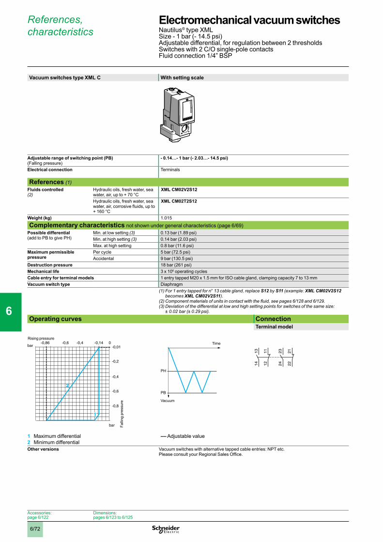
6/72
References, characteristics
Vacuum switches type XML C With setting scale
Adjustable range of switching point (PB) (Falling pressure)
- 0.14…- 1 bar (- 2.03…- 14.5 psi)
Electrical connection Terminals
References (1)Fluids controlled (2)
Hydraulic oils, fresh water, sea water, air, up to + 70 °C
XML CM02V2S12
Hydraulic oils, fresh water, sea water, air, corrosive fluids, up to + 160 °C
XML CM02T2S12
Weight (kg) 1.015
Complementary characteristics not shown under general characteristics (page 6/69)Possible differential (add to PB to give PH)
Min. at low setting (3) 0.13 bar (1.89 psi)Min. at high setting (3) 0.14 bar (2.03 psi)Max. at high setting 0.8 bar (11.6 psi)
Maximum permissible pressure
Per cycle 5 bar (72.5 psi)Accidental 9 bar (130.5 psi)
Destruction pressure 18 bar (261 psi)Mechanical life 3 x 10⁶ operating cyclesCable entry for terminal models 1 entry tapped M20 x 1.5 mm for ISO cable gland, clamping capacity 7 to 13 mmVacuum switch type Diaphragm
(1) For 1 entry tapped for n° 13 cable gland, replace S12 by S11 (example: XML CM02V2S12 becomes XML CM02V2S11).
(2)Componentmaterialsofunitsincontactwiththefluid,seepages6/128 and 6/129.(3)Deviationofthedifferentialatlowandhighsettingpointsforswitchesofthesamesize:
± 0.02 bar (± 0.29 psi). Operating curves Connection
Terminal model
1 Maximum differential2 Minimum differential
–– Adjustable value
Other versions Vacuum switches with alternative tapped cable entries: NPT etc. Please consult your Regional Sales Office.
bar
bar -0,010-0,14-0,4-0,6-0,86
-0,2
-0,4
-0,6
-0,8
2
1
Falli
ng p
ress
ure
Rising pressure
PH
PB
Time
Vacuum
23
24
22
21
13
14
12
11
Accessories:page 6/122
Dimensions:pages 6/123 to 6/125
Electromechanical vacuum switches 0 Nautilus® type XMLSize - 1 bar (- 14.5 psi)Adjustable differential, for regulation between 2 thresholdsSwitches with 2 C/O single-pole contactsFluid connection 1/4” BSP
1
2
3
4
5
6
7
8
9
10
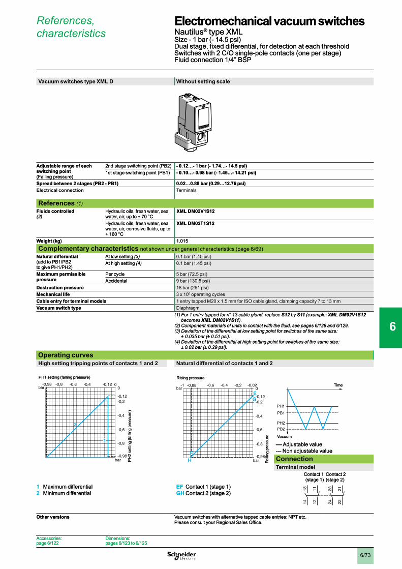
6/73
References, characteristics
Vacuum switches type XML D Without setting scale
Adjustable range of each switching point (Falling pressure)
2nd stage switching point (PB2) - 0.12…- 1 bar (- 1.74…- 14.5 psi) 1st stage switching point (PB1) - 0.10…- 0.98 bar (- 1.45…- 14.21 psi)
Spread between 2 stages (PB2 - PB1) 0.02…0.88 bar (0.29…12.76 psi)Electrical connection Terminals
References (1)Fluids controlled (2)
Hydraulic oils, fresh water, sea water, air, up to + 70 °C
XML DM02V1S12
Hydraulic oils, fresh water, sea water, air, corrosive fluids, up to + 160 °C
XML DM02T1S12
Weight (kg) 1.015
Complementary characteristics not shown under general characteristics (page 6/69)Natural differential (add to PB1/PB2 to give PH1/PH2)
At low setting (3) 0.1 bar (1.45 psi)At high setting (4) 0.1 bar (1.45 psi)
Maximum permissible pressure
Per cycle 5 bar (72.5 psi)Accidental 9 bar (130.5 psi)
Destruction pressure 18 bar (261 psi)Mechanical life 3 x 10⁶ operating cyclesCable entry for terminal models 1 entry tapped M20 x 1.5 mm for ISO cable gland, clamping capacity 7 to 13 mmVacuum switch type Diaphragm
(1) For 1 entry tapped for n° 13 cable gland, replace S12 by S11 (example: XML DM02V1S12 becomes XML DM02V1S11).
(2)Componentmaterialsofunitsincontactwiththefluid,seepages6/128 and 6/129.(3)Deviationofthedifferentialatlowsettingpointforswitchesofthesamesize:
± 0.035 bar (± 0.51 psi). (4)Deviationofthedifferentialathighsettingpointforswitchesofthesamesize:
± 0.02 bar (± 0.29 psi).
Operating curvesHigh setting tripping points of contacts 1 and 2 Natural differential of contacts 1 and 2
–– Adjustable value--- Non adjustable valueConnectionTerminal model
Contact 1 (stage 1)
Contact 2 (stage 2)
1 Maximum differential2 Minimum differential
EF Contact 1 (stage 1)GH Contact 2 (stage 2)
Other versions Vacuum switches with alternative tapped cable entries: NPT etc. Please consult your Regional Sales Office.
bar
bar 00-0,12-0,4-0,6-0,98
-0,2-0,12
-0,4
-0,6
-0,8
-0,98
2
1
-0,8
PH1 setting (falling pressure)
PH
2 se
tting
(fal
ling
pres
sure
)
Falli
ng p
ress
ure
Rising pressure
bar
bar 0-0,02-0,2-0,4-0,6-0,88
-0,2-0,12
-0,4
-0,6
-0,8
-0,98
-1
E
H
G
F
PH1
PH2
PB2
PB1
Time
Vacuum
23
24
22
21
13
14
12
11
Accessories:page 6/122
Dimensions:pages 6/123 to 6/125
Electromechanical vacuum switches 0 Nautilus® type XMLSize - 1 bar (- 14.5 psi)Dual stage, fixed differential, for detection at each thresholdSwitches with 2 C/O single-pole contacts (one per stage)Fluid connection 1/4” BSP
1
2
3
4
5
6
7
8
9
10

6/74
References, characteristics
Vacuum switches type XML B With setting scale
Adjustable range of switching point (PB) (Falling pressure)
- 20…- 200 mbar (- 0.29…- 2.9 psi)
Electrical connection Terminals
References (1)Fluids controlled (2)
Hydraulic oils, air, up to + 160 °C XML BM03R2S12Fresh water, sea water, corrosive fluids, up to + 160 °C
XML BM03S2S12
Weight (kg) 3.310
Complementary characteristics not shown under general characteristics (page 6/69)Possible differential (add to PB to give PH)
Min. at low setting (3) 18 mbar (0.26 psi)Min. at high setting (3) 18 mbar (0.26 psi)Max. at high setting 180 mbar (2.6 psi)
Maximum permissible pressure
Per cycle 1 bar (14.5 psi)Accidental 2 bar (29 psi)
Destruction pressure 3.5 bar (50.75 psi)Mechanical life 3 x 10⁶ operating cyclesCable entry for terminal models 1 entry tapped M20 x 1.5 mm for ISO cable gland, clamping capacity 7 to 13 mmVacuum switch type Diaphragm
(1) For 1 entry tapped for n° 13 cable gland, replace S12 by S11 (example: XML BM03R2S12 becomes XML BM03R2S11).
(2)Componentmaterialsofunitsincontactwiththefluid,seepages6/128 and 6/129.(3)Deviationofthedifferentialatlowandhighsettingpointsforswitchesofthesamesize:
± 2 mbar (± 0.29 psi). Operating curves Connection
Terminal model
1 Maximum differential2 Minimum differential
–– Adjustable value
Other versions Vacuum switches with alternative tapped cable entries: NPT etc. Please consult your Regional Sales Office.
mbar
mbar 0-2-40-80-120-160
-40
-20
-80
-120
-160
-200
-182
1
2
-20Rising pressure
Falli
ng p
ress
ure
PH
PB
Time
Vacuum
1314 12
11
Accessories:page 6/122
Dimensions:pages 6/123 to 6/125
Electromechanical vacuum switches 0 Nautilus® type XMLSize - 200 mbar (- 2.9 psi)Adjustable differential, for regulation between 2 thresholdsSwitches with 1 C/O single-pole contactFluid connection 1/4” BSP
1
2
3
4
5
6
7
8
9
10

6/75
References, characteristics
Pressure switches type XML B With setting scale Without setting scale
Adjustable range of switching point (PH) (Rising pressure)
2.6…50 mbar (0.038…0.72 psi)
Electrical connection Terminals
References (1)Fluids controlled (2)
Hydraulic oils, air, up to + 160 °C XML BL05R2S12 XML BL05R1S12Fresh water, sea water, corrosive fluids, up to + 160 °C
XML BL05S2S12 XML BL05S1S12
Weight (kg) 2.420
Complementary characteristics not shown under general characteristics (page 6/69)Possible differential (subtract from PH to give PB)
Min. at low setting (3) 1.4 mbar (0.02 psi)Min. at high setting (4) 4 mbar (0.06 psi)Max. at high setting 40 mbar (0.58 psi)
Maximum permissible pressure
Per cycle 62.5 mbar (0.90 psi)Accidental 112.5 mbar (1.63 psi)
Destruction pressure 225 mbar (3.26 psi)Mechanical life 6 x 10⁶ operating cyclesCable entry for terminal models 1 entry tapped M20 x 1.5 mm for ISO cable gland, clamping capacity 7 to 13 mmPressure switch type Diaphragm
(1) For 1 entry tapped for n° 13 cable gland, replace S12 by S11 (example: XML BL05R2S12 becomes XML BL05R2S11).
(2)Componentmaterialsofunitsincontactwiththefluid,seepages6/128 and 6/129.(3)Deviationofthedifferentialatlowsettingpointforswitchesofthesamesize:
- 0.8 mbar, + 1.1 mbar (- 0.01 psi, + 0.02 psi).(4)Deviationofthedifferentialathighsettingpointforswitchesofthesamesize:
± 1.4 mbar, (+ 0.02 psi). Operating curves Connection
Terminal model
1 Maximum differential2 Minimum differential
–– Adjustable value
Other versions Pressure switches with DIN 43650A connector or with alternative tapped cable entries: NPT etc. Please consult your Regional Sales Office.
mbar
mbar
010 30 4640
10
20
30
1,2
2,6
40
50
2
1
20Falling pressure
Ris
ing
pres
sure
PH
PB
Pressure
Time
1314 12
11
Accessories:page 6/122
Dimensions:pages 6/123 to 6/125
Electromechanical pressure switches 0 Nautilus® type XMLSize 50 mbar (0.72 psi)Adjustable differential, for regulation between 2 thresholdsSwitches with 1 C/O single-pole contactFluid connection 1/4” BSP
1
2
3
4
5
6
7
8
9
10
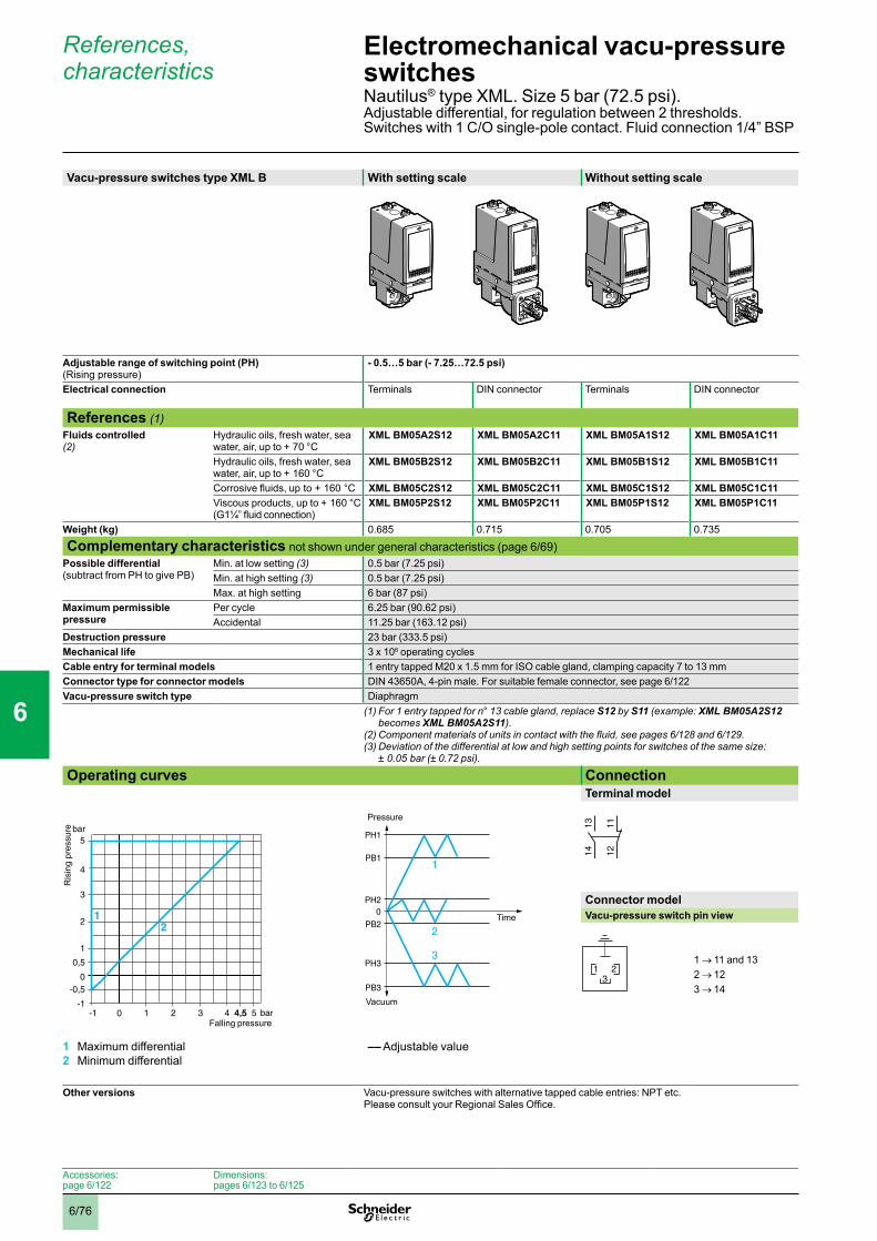
6/76
References, characteristics
Vacu-pressure switches type XML B With setting scale Without setting scale
Adjustable range of switching point (PH) (Rising pressure)
- 0.5…5 bar (- 7.25…72.5 psi)
Electrical connection Terminals DIN connector Terminals DIN connector
References (1)Fluids controlled (2)
Hydraulic oils, fresh water, sea water, air, up to + 70 °C
XML BM05A2S12 XML BM05A2C11 XML BM05A1S12 XML BM05A1C11
Hydraulic oils, fresh water, sea water, air, up to + 160 °C
XML BM05B2S12 XML BM05B2C11 XML BM05B1S12 XML BM05B1C11
Corrosive fluids, up to + 160 °C XML BM05C2S12 XML BM05C2C11 XML BM05C1S12 XML BM05C1C11Viscous products, up to + 160 °C(G1¼” fluid connection)
XML BM05P2S12 XML BM05P2C11 XML BM05P1S12 XML BM05P1C11
Weight (kg) 0.685 0.715 0.705 0.735
Complementary characteristics not shown under general characteristics (page 6/69)Possible differential (subtract from PH to give PB)
Min. at low setting (3) 0.5 bar (7.25 psi)Min. at high setting (3) 0.5 bar (7.25 psi)Max. at high setting 6 bar (87 psi)
Maximum permissible pressure
Per cycle 6.25 bar (90.62 psi)Accidental 11.25 bar (163.12 psi)
Destruction pressure 23 bar (333.5 psi)Mechanical life 3 x 10⁶ operating cyclesCable entry for terminal models 1 entry tapped M20 x 1.5 mm for ISO cable gland, clamping capacity 7 to 13 mmConnector type for connector models DIN 43650A, 4-pin male. For suitable female connector, see page 6/122Vacu-pressure switch type Diaphragm
(1) For 1 entry tapped for n° 13 cable gland, replace S12 by S11 (example: XML BM05A2S12 becomes XML BM05A2S11).
(2)Componentmaterialsofunitsincontactwiththefluid,seepages6/128 and 6/129.(3)Deviationofthedifferentialatlowandhighsettingpointsforswitchesofthesamesize:
± 0.05 bar (± 0.72 psi). Operating curves Connection
Terminal model
Connector modelVacu-pressure switch pin view
1 → 11 and 132 → 123 → 14
1 Maximum differential2 Minimum differential
–– Adjustable value
Other versions Vacu-pressure switches with alternative tapped cable entries: NPT etc. Please consult your Regional Sales Office.
4,5-1-1
-0,5
0,5
1 2 3 4 4,5 5
4
5
0
3
2
1
0
bar
bar
21
Ris
ing
pres
sure
Falling pressure
PH1
PB1
PH2
PB2
PH3
PB3
0
1
2
3
Time
Vacuum
Pressure
1314 12
11
321
Accessories:page 6/122
Dimensions:pages 6/123 to 6/125
Electromechanical vacu-pressure switches 0 Nautilus® type XML. Size 5 bar (72.5 psi).Adjustable differential, for regulation between 2 thresholds. Switches with 1 C/O single-pole contact. Fluid connection 1/4” BSP
1
2
3
4
5
6
7
8
9
10

6/77
References, characteristics
Vacu-pressure switches type XML C With setting scale
Adjustable range of switching point (PH) (Rising pressure)
- 0.55…5 bar (- 7.97…72.5 psi)
Electrical connection Terminals
References (1)Fluids controlled (2)
Hydraulic oils, fresh water, sea water, air, up to + 70 °C
XML CM05A2S12
Hydraulic oils, fresh water, sea water, air, up to + 160 °C
XML CM05B2S12
Corrosive fluids, up to + 160 °C XML CM05C2S12Weight (kg) 0.685
Complementary characteristics not shown under general characteristics (page 6/69)Possible differential (subtract from PH to give PB)
Min. at low setting (3) 0.45 bar (6.52 psi)Min. at high setting (3) 0.45 bar (6.52 psi)Max. at high setting 6 bar (87 psi)
Maximum permissible pressure
Per cycle 6.25 bar (90.62 psi)Accidental 11.25 bar (163.12 psi)
Destruction pressure 23 bar (333.5 psi)Mechanical life 3 x 10⁶ operating cyclesCable entry for terminal models 1 entry tapped M20 x 1.5 mm for ISO cable gland, clamping capacity 7 to 13 mmVacu-pressure switch type Diaphragm
(1) For 1 entry tapped for n° 13 cable gland, replace S12 by S11 (example: XML CM05A2S12 becomes XML CM05A2S11).
(2)Componentmaterialsofunitsincontactwiththefluid,seepages6/128 and 6/129.(3)Deviationofthedifferentialatlowandhighsettingpointsforswitchesofthesamesize:
± 0.1 bar (± 1.45 psi). Operating curves Connection
Terminal model
Connector modelVacu-pressure switch pin view
1 → 11 and 132 → 123 → 14
1 Maximum differential2 Minimum differential
–– Adjustable value
Other versions Vacu-pressure switches with alternative tapped cable entries: NPT etc. Please consult your Regional Sales Office.
4,55-1-1
-0,55
0,5
1 2 3 4 5
4
5
0
3
2
1
0
bar
bar
21
Ris
ing
pres
sure
Falling pressure
PH1
PB1
PH2
PB2
PH3
PB3
0
1
2
3
Time
Vacuum
Pressure 23
24
22
21
13
14
12
11
321
Accessories:page 6/122
Dimensions:pages 6/123 to 6/125
Electromechanical vacu-pressure switches 0 Nautilus® type XML. Size 5 bar (72.5 psi).Adjustable differential, for regulation between 2 thresholds.Switches with 2 C/O single-pole contacts. Fluid connection 1/4” BSP
1
2
3
4
5
6
7
8
9
10

6/78
References, characteristics
Pressure switches type XML B With setting scale 30 bar (435 psi) overpressureWith setting scale
Adjustable range of switching point (PH) (Rising pressure)
45…350 mbar (0.65…5.07 psi) 42…330 mbar (0.61…4.78 psi)
Electrical connection Terminals DIN connector Terminals
References (1)Fluids controlled (2)
Hydraulic oils, air, up to + 160 °C XML BL35R2S12 XML BL35R2C11 XML BS35R2S12Fresh water, sea water, corrosive fluids, up to + 160 °C
XML BL35S2S12 XML BL35S2C11 –
Viscous products, up to + 160 °C(G1¼” fluid connection)
XML BL35P2S12 XML BL35P2C11 –
Weight (kg) 2.575 2.590 3.500
Complementary characteristics not shown under general characteristics (page 6/69)Possible differential (subtract from PH to give PB)
Min. at low setting (3) 42 mbar (0.60 psi) 33 mbar (0.48 psi)Min. at high setting (4) 50 mbar (0.72 psi) 58 mbar (0.84 psi)Max. at high setting 300 mbar (4.35 psi) 250 mbar (3.62 psi)
Maximum permissible pressure
Per cycle 1.25 bar (18.12 psi) 30 bar (435 psi)Accidental 2.25 bar (32.62 psi) 37.5 bar (543.75 psi)
Destruction pressure 4.5 bar (65.25 psi) 67.5 bar (978.75 psi)Mechanical life 4 million operating cycles 2 million operating cyclesCable entry for terminal models 1 entry tapped M20 x 1.5 mm for ISO cable gland, clamping capacity 7 to 13 mmConnector type for connector models DIN 43650A, 4-pin male. For suitable female connector, see page 6/122Pressure switch type Diaphragm
(1) For 1 entry tapped for n° 13 cable gland, replace S12 by S11 (example: XML BL35R2S12 becomes XML BL35R2S11).
(2)Componentmaterialsofunitsincontactwiththefluid,seepages6/128 and 6/129.(3)Deviationofthedifferentialatlowsettingpointforswitchesofthesamesize:
- 8 mbar, + 3 mbar (- 0.12 psi, + 0.04 psi). (4)Deviationofthedifferentialathighsettingpointforswitchesofthesamesize:
± 8 mbar (± 0.11 psi). Operating curves Connection
Terminal model
Connector modelPressure switch connector pin view
1 → 11 and 132 → 123 → 14
1 Maximum differential2 Minimum differential
–– Adjustable value
Other versions Pressure switches with alternative tapped cable entries: NPT etc. Please consult your Regional Sales Office.
3 50 mbar
mbar
0100 200 300
100
200
300
350
45
2
1
Ris
ing
pres
sure
Falling pressure
PH
PB
Time
Pressure
1314 12
11
321
Accessories:page 6/122
Dimensions:pages 6/123 to 6/125
Electromechanical pressure switches 0 Nautilus® type XMLSize 350 mbar (5.07 psi) Adjustable differential, for regulation between 2 thresholdsSwitches with 1 C/O single-pole contactFluid connection 1/4” BSP
1
2
3
4
5
6
7
8
9
10
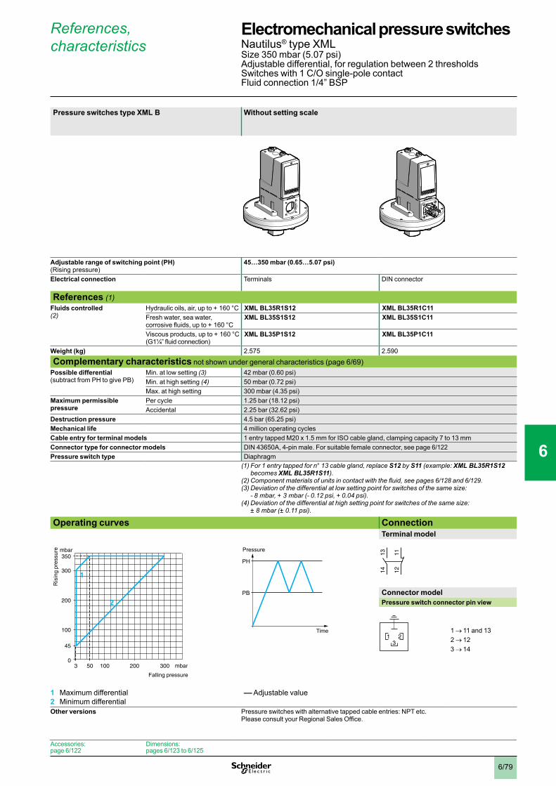
6/79
References, characteristics
Pressure switches type XML B Without setting scale
Adjustable range of switching point (PH) (Rising pressure)
45…350 mbar (0.65…5.07 psi)
Electrical connection Terminals DIN connector
References (1)Fluids controlled (2)
Hydraulic oils, air, up to + 160 °C XML BL35R1S12 XML BL35R1C11Fresh water, sea water, corrosive fluids, up to + 160 °C
XML BL35S1S12 XML BL35S1C11
Viscous products, up to + 160 °C(G1¼” fluid connection)
XML BL35P1S12 XML BL35P1C11
Weight (kg) 2.575 2.590
Complementary characteristics not shown under general characteristics (page 6/69)Possible differential (subtract from PH to give PB)
Min. at low setting (3) 42 mbar (0.60 psi)Min. at high setting (4) 50 mbar (0.72 psi)Max. at high setting 300 mbar (4.35 psi)
Maximum permissible pressure
Per cycle 1.25 bar (18.12 psi)Accidental 2.25 bar (32.62 psi)
Destruction pressure 4.5 bar (65.25 psi)Mechanical life 4 million operating cyclesCable entry for terminal models 1 entry tapped M20 x 1.5 mm for ISO cable gland, clamping capacity 7 to 13 mmConnector type for connector models DIN 43650A, 4-pin male. For suitable female connector, see page 6/122Pressure switch type Diaphragm
(1) For 1 entry tapped for n° 13 cable gland, replace S12 by S11 (example: XML BL35R1S12 becomes XML BL35R1S11).
(2)Componentmaterialsofunitsincontactwiththefluid,seepages6/128 and 6/129.(3)Deviationofthedifferentialatlowsettingpointforswitchesofthesamesize:
- 8 mbar, + 3 mbar (- 0.12 psi, + 0.04 psi). (4)Deviationofthedifferentialathighsettingpointforswitchesofthesamesize:
± 8 mbar (± 0.11 psi). Operating curves Connection
Terminal model
Connector modelPressure switch connector pin view
1 → 11 and 132 → 123 → 14
1 Maximum differential2 Minimum differential
–– Adjustable value
Other versions Pressure switches with alternative tapped cable entries: NPT etc. Please consult your Regional Sales Office.
3 50 mbar
mbar
0100 200 300
100
200
300
350
45
2
1
Ris
ing
pres
sure
Falling pressure
PH
PB
Time
Pressure
1314 12
11
321
Accessories:page 6/122
Dimensions:pages 6/123 to 6/125
Electromechanical pressure switches 0 Nautilus® type XMLSize 350 mbar (5.07 psi) Adjustable differential, for regulation between 2 thresholdsSwitches with 1 C/O single-pole contactFluid connection 1/4” BSP
1
2
3
4
5
6
7
8
9
10

6/80
References, characteristics
Pressure switches type XML C With setting scale 30 bar (435 psi) overpressureWith setting scale
Adjustable range of switching point (PH) (Rising pressure)
45…350 mbar (0.65…5.07 psi) 42…330 mbar (0.61…4.78 psi)
Electrical connection Terminals
References (1)Fluids controlled (2)
Hydraulic oils, air, up to + 160 °C XML CL35R2S12 XML CS35R2S12Fresh water, sea water, corrosive fluids, up to + 160 °C
XML CL35S2S12 –
Weight (kg) 2.575 3.500
Complementary characteristics not shown under general characteristics (page 6/69)Possible differential (subtract from PH to give PB)
Min. at low setting (3) 20 mbar (0.29 psi) 40 mbar (0.58 psi)Min. at high setting (3) 35 mbar (0.51 psi) 88 mbar (1.27 psi)Max. at high setting 300 mbar (4.35 psi) 230 mbar (3.33 psi)
Maximum permissible pressure
Per cycle 1.25 bar (18.12 psi) 30 bar (435 psi)Accidental 2.25 bar (32.62 psi) 37.5 bar (543.75 psi)
Destruction pressure 4.5 bar (65.25 psi) 67.5 bar (978.75 psi)Mechanical life 4 million operating cycles 2 million operating cyclesCable entry for terminal models 1 entry tapped M20 x 1.5 mm for ISO cable gland, clamping capacity 7 to 13 mmPressure switch type Diaphragm
(1) For 1 entry tapped for n° 13 cable gland, replace S12 by S11 (example: XML CL35R2S12 becomes XML CL35R2S11).
(2)Componentmaterialsofunitsincontactwiththefluid,seepages6/128 and 6/129.(3)Deviationofthedifferentialatlowsettingpointforswitchesofthesamesize:
± 20 mbar (± 0.29 psi). Operating curves Connection
Terminal model
1 Maximum differential2 Minimum differential
–– Adjustable value
Other versions Pressure switches with alternative tapped cable entries: NPT etc. Please consult your Regional Sales Office.
0 25 50 mbar
mbar
0100 200 315
100
200
300
350
45
2
1
Ris
ing
pres
sure
Falling pressure
PH
PB
Time
Pressure
23
24
22
21
13
14
12
11
Accessories:page 6/122
Dimensions:pages 6/123 to 6/125
Electromechanical pressure switches 0 Nautilus® type XMLSize 350 mbar (5.07 psi) Adjustable differential, for regulation between 2 thresholdsSwitches with 2 C/O single-pole contactsFluid connection 1/4” BSP
1
2
3
4
5
6
7
8
9
10
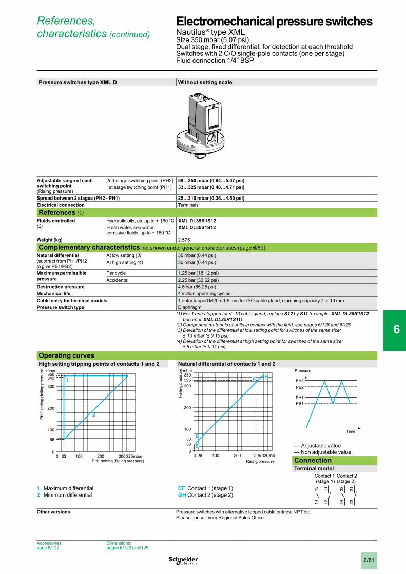
6/81
References, characteristics (continued)
Pressure switches type XML D Without setting scale
Adjustable range of each switching point (Rising pressure)
2nd stage switching point (PH2) 58…350 mbar (0.84…5.07 psi) 1st stage switching point (PH1) 33…325 mbar (0.48…4.71 psi)
Spread between 2 stages (PH2 - PH1) 25…310 mbar (0.36…4.50 psi) Electrical connection Terminals
References (1)Fluids controlled (2)
Hydraulic oils, air, up to + 160 °C XML DL35R1S12Fresh water, sea water, corrosive fluids, up to + 160 °C
XML DL35S1S12
Weight (kg) 2.575
Complementary characteristics not shown under general characteristics (page 6/69)Natural differential (subtract from PH1/PH2 to give PB1/PB2)
At low setting (3) 30 mbar (0.44 psi)At high setting (4) 30 mbar (0.44 psi)
Maximum permissible pressure
Per cycle 1.25 bar (18.12 psi)Accidental 2.25 bar (32.62 psi)
Destruction pressure 4.5 bar (65.25 psi)Mechanical life 4 million operating cyclesCable entry for terminal models 1 entry tapped M20 x 1.5 mm for ISO cable gland, clamping capacity 7 to 13 mmPressure switch type Diaphragm
(1) For 1 entry tapped for n° 13 cable gland, replace S12 by S11 (example: XML DL35R1S12 becomes XML DL35R1S11).
(2)Componentmaterialsofunitsincontactwiththefluid,seepages6/128 and 6/129.(3)Deviationofthedifferentialatlowsettingpointforswitchesofthesamesize:
± 10 mbar (± 0.15 psi).(4)Deviationofthedifferentialathighsettingpointforswitchesofthesamesize:
± 8 mbar (± 0.11 psi). Operating curvesHigh setting tripping points of contacts 1 and 2 Natural differential of contacts 1 and 2
–– Adjustable value--- Non adjustable valueConnectionTerminal model
Contact 1 (stage 1)
Contact 2 (stage 2)
1 Maximum differential2 Minimum differential
EF Contact 1 (stage 1)GH Contact 2 (stage 2)
Other versions Pressure switches with alternative tapped cable entries: NPT etc. Please consult your Regional Sales Office.
Accessories:page 6/122
Dimensions:pages 6/123 to 6/125
0 33 mbar
mbar
0100 200 300 325
100
200
300
343350
58
2
1
PH
2 se
tting
(fal
ling
pres
sure
)
PH1 setting (falling pressure)3 28 mbar
mbar
0100 200 295 320
100
200
300
325350
3358
E
G
F H
Falli
ng p
ress
ure
Rising pressure
PH2
PH1
PB1
PB2
Time
Pressure
23
24
22
21
13
14
12
11
Electromechanical pressure switches 0 Nautilus® type XMLSize 350 mbar (5.07 psi) Dual stage, fixed differential, for detection at each thresholdSwitches with 2 C/O single-pole contacts (one per stage)Fluid connection 1/4” BSP
1
2
3
4
5
6
7
8
9
10

6/82
References, characteristics
Pressure switches type XML A With setting scale Without setting scale
Adjustable range of switching point (PH) (Rising pressure)
0.03…1 bar (0.435…14.5 psi)
Electrical connection Terminals DIN connector Terminals DIN connector
References (1)Fluids controlled (2)
Hydraulic oils, air, up to + 160 °C XML A001R2S12 XML A001R2C11 XML A001R1S12 XML A001R1C11Fresh water, sea water, corrosive fluids, up to + 160 °C
XML A001S2S12 XML A001S2C11 XML A001S1S12 XML A001S1C11
Weight (kg) 2.555 2.570 2.555 2.570
Complementary characteristics not shown under general characteristics (page 6/69)Natural differential (subtract from PH to give PB)
At low setting (3) 0.02 bar (0.29 psi)At high setting (3) 0.04 bar (0.58 psi)
Maximum permissible pressure
Per cycle 1.25 bar (18.12 psi)Accidental 2.25 bar (32.62 psi)
Destruction pressure 4.5 bar (65.25 psi)Mechanical life 4 x 10⁶ operating cyclesCable entry for terminal models 1 entry tapped M20 x 1.5 mm for ISO cable gland, clamping capacity 7 to 13 mmConnector type for connector models DIN 43650A, 4-pin male. For suitable female connector, see page 6/122Pressure switch type Diaphragm
(1) For 1 entry tapped for n° 13 cable gland, replace S12 by S11 (example: XML A001R2S12 becomes XML A001R2S11).
(2)Componentmaterialsofunitsincontactwiththefluid,seepages6/128 and 6/129.(3)Deviationofthedifferentialathighandlowsettingpointsforswitchesofthesamesize:
± 0.01 bar (± 0.14 psi). Operating curves Connection
Terminal model
Connector modelPressure switch connector pin view
1 → 11 and 132 → 123 → 14
–– Adjustable value--- Non adjustable value
Other versions Pressure switches with alternative tapped cable entries: NPT etc. Please consult your Regional Sales Office.
bar
bar
0
0,8
0,6
0,4
0,2
0,03
1
0,960,80,60,40,20,01
Ris
ing
pres
sure
Falling pressure
PH
PB
Time
Pressure 1314 12
11
321
Accessories:page 6/122
Dimensions:pages 6/123 to 6/125
Electromechanical pressure switches 0 Nautilus® type XMLSize 1 bar (14.5 psi)Fixed differential, for detection of a single thresholdSwitches with 1 C/O single-pole contactFluid connection 1/4” BSP
1
2
3
4
5
6
7
8
9
10

6/83
References, characteristics
Pressure switches type XML B With setting scale Without setting scale
Adjustable range of switching point (PH) (Rising pressure)
0.05…1 bar (0.72…14.5 psi)
Electrical connection Terminals DIN connector Terminals DIN connector
References (1)Fluids controlled (2)
Hydraulic oils, air, up to + 160 °C XML B001R2S12 XML B001R2C11 XML B001R1S12 XML B001R1C11Fresh water, sea water, corrosive fluids, up to + 160 °C
XML B001S2S12 XML B001S2C11 XML B001S1S12 XML B001S1C11
Viscous products, up to + 160 °C(G1¼” fluid connection)
XML B001P2S12 XML B001P2C11 XML B001P1S12 XML B001P1C11
Weight (kg) 2.575 2.590 2.575 2.590
Complementary characteristics not shown under general characteristics (page 6/69)Possible differential (subtract from PH to give PB)
Min. at low setting (3) 0.04 bar (0.58 psi)Min. at high setting (4) 0.06 bar (0.87 psi)Max. at high setting 0.75 bar (10.87 psi)
Maximum permissible pressure
Per cycle 1.25 bar (18.12 psi)Accidental 2.25 bar (32.62 psi)
Destruction pressure 4.5 bar (65.25 psi)Mechanical life 4 x 10⁶ operating cyclesCable entry for terminal models 1 entry tapped M20 x 1.5 mm for ISO cable gland, clamping capacity 7 to 13 mmConnector type for connector models DIN 43650A, 4-pin male. For suitable female connector, see page 6/122Pressure switch type Diaphragm
(1) For 1 entry tapped for n° 13 cable gland, replace S12 by S11 (example: XML B001R2S12 becomes XML B001R2S11).
(2)Componentmaterialsofunitsincontactwiththefluid,seepages6/128 and 6/129.(3)Deviationofthedifferentialatlowsettingpointforswitchesofthesamesize:
± 10 mbar (± 0.14 psi). (4)Deviationofthedifferentialathighsettingpointforswitchesofthesamesize:
± 20 mbar (± 0.29 psi). Operating curves Connection
Terminal model
Connector modelPressure switch connector pin view
1 → 11 and 132 → 123 → 14
1 Maximum differential2 Minimum differential
–– Adjustable value
Other versions Pressure switches with alternative tapped cable entries: NPT etc. Please consult your Regional Sales Office.
bar
bar
00,05
0,8
0,6
0,4
0,2
1
0,940,80,60,40,250,01
1
2
Ris
ing
pres
sure
Falling pressure
PH
PB
Time
Pressure 1314 12
11
321
Accessories:page 6/122
Dimensions:pages 6/123 to 6/125
Electromechanical pressure switches 0 Nautilus® type XML Size 1 bar (14.5 psi)Adjustable differential, for regulation between 2 thresholdsSwitches with 1 C/O single-pole contactFluid connection 1/4” BSP
1
2
3
4
5
6
7
8
9
10

6/84
References, characteristics
Pressure switches type XML C With setting scale
Adjustable range of switching point (PH) (Rising pressure)
0.05…1 bar (0.725…14.5 psi)
Electrical connection Terminals
References (1)Fluids controlled (2)
Hydraulic oils, air, up to + 160 °C XML C001R2S12Fresh water, sea water, corrosive fluids, up to + 160 °C
XML C001S2S12
Weight (kg) 2.555
Complementary characteristics not shown under general characteristics (page 6/69)Possible differential (subtract from PH to give PB)
Min. at low setting (3) 0.03 bar (0.43 psi)Min. at high setting (4) 0.04 bar (0.58 psi)Max. at high setting 0.8 bar (11.6 psi)
Maximum permissible pressure
Per cycle 1.25 bar (18.12 psi)Accidental 2.25 bar (32.62 psi)
Destruction pressure 4.5 bar (65.25 psi)Mechanical life 4 x 10⁶ operating cyclesCable entry for terminal models 1 entry tapped M20 x 1.5 mm for ISO cable gland, clamping capacity 7 to 13 mmPressure switch type Diaphragm
(1) For 1 entry tapped for n° 13 cable gland, replace S12 by S11 (example: XML C001R2S12 becomes XML C001R2S11).
(2)Componentmaterialsofunitsincontactwiththefluid,seepages6/128 and 6/129.(3)Deviationofthedifferentialatlowsettingpointforswitchesofthesamesize:
± 0.01 bar (± 0.14 psi). (4)Deviationofthedifferentialathighsettingpointforswitchesofthesamesize:
± 0.03 bar (± 0.43 psi). Operating curves Connection
Terminal model
1 Maximum differential2 Minimum differential
–– Adjustable value
Other versions Pressure switches with alternative tapped cable entries: NPT etc. Please consult your Regional Sales Office.
bar
bar
00,05
0,6
0,4
0,2
1
0,960,80,60,40,20,02
1
2
Ris
ing
pres
sure
Falling pressure
PH
PB
Time
Pressure
23
24
22
21
13
14
12
11
Accessories:page 6/122
Dimensions:pages 6/123 to 6/125
Electromechanical pressure switches 0 Nautilus® type XML Size 1 bar (14.5 psi)Adjustable differential, for regulation between 2 thresholdsSwitches with 2 C/O single-pole contactsFluid connection 1/4” BSP
1
2
3
4
5
6
7
8
9
10
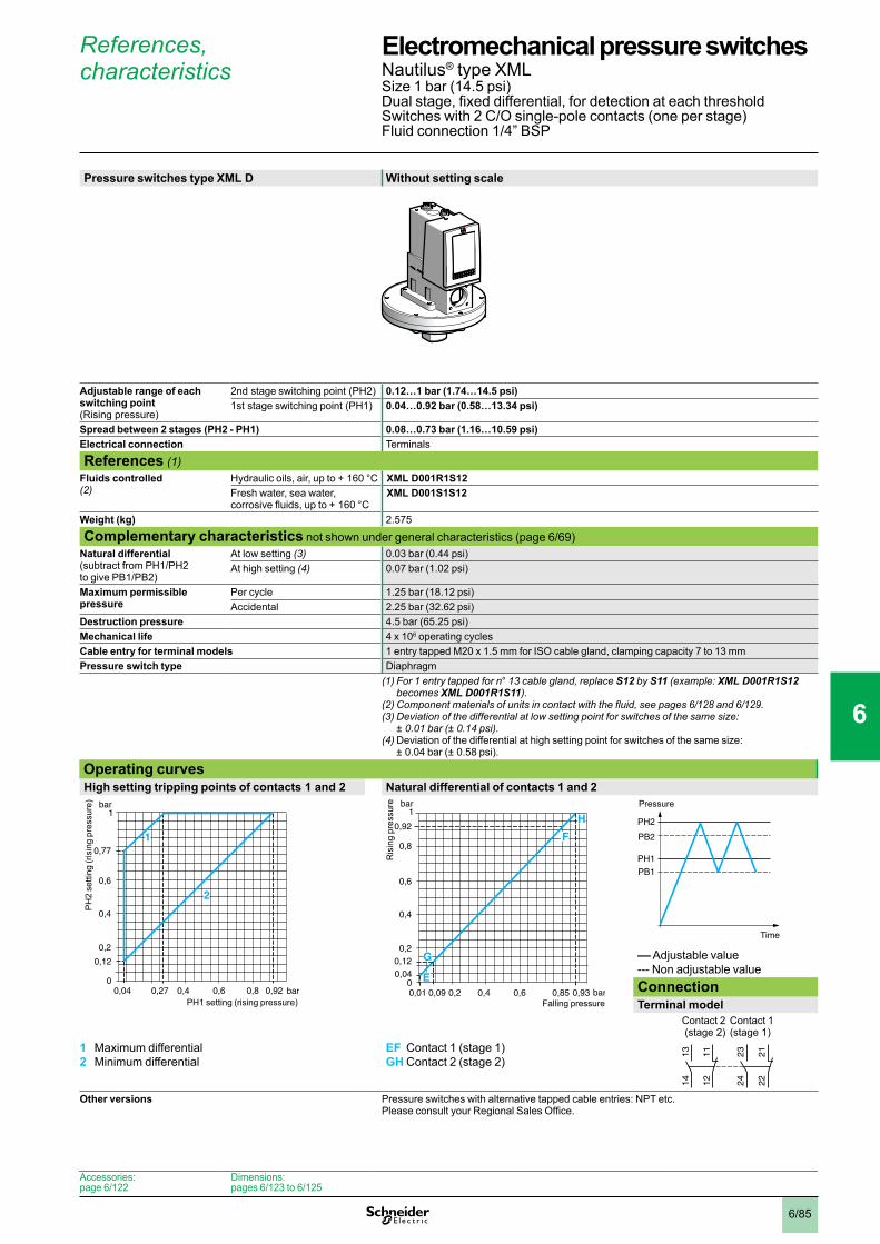
6/85
References, characteristics
Pressure switches type XML D Without setting scale
Adjustable range of each switching point (Rising pressure)
2nd stage switching point (PH2) 0.12…1 bar (1.74…14.5 psi) 1st stage switching point (PH1) 0.04…0.92 bar (0.58…13.34 psi)
Spread between 2 stages (PH2 - PH1) 0.08…0.73 bar (1.16…10.59 psi) Electrical connection Terminals
References (1)Fluids controlled (2)
Hydraulic oils, air, up to + 160 °C XML D001R1S12Fresh water, sea water, corrosive fluids, up to + 160 °C
XML D001S1S12
Weight (kg) 2.575
Complementary characteristics not shown under general characteristics (page 6/69)Natural differential (subtract from PH1/PH2 to give PB1/PB2)
At low setting (3) 0.03 bar (0.44 psi)At high setting (4) 0.07 bar (1.02 psi)
Maximum permissible pressure
Per cycle 1.25 bar (18.12 psi)Accidental 2.25 bar (32.62 psi)
Destruction pressure 4.5 bar (65.25 psi)Mechanical life 4 x 10⁶ operating cyclesCable entry for terminal models 1 entry tapped M20 x 1.5 mm for ISO cable gland, clamping capacity 7 to 13 mmPressure switch type Diaphragm
(1) For 1 entry tapped for n° 13 cable gland, replace S12 by S11 (example: XML D001R1S12 becomes XML D001R1S11).
(2)Componentmaterialsofunitsincontactwiththefluid,seepages6/128 and 6/129.(3)Deviationofthedifferentialatlowsettingpointforswitchesofthesamesize:
± 0.01 bar (± 0.14 psi).(4) Deviation of the differential at high setting point for switches of the same size:
± 0.04 bar (± 0.58 psi). Operating curvesHigh setting tripping points of contacts 1 and 2 Natural differential of contacts 1 and 2
–– Adjustable value--- Non adjustable valueConnectionTerminal model
Contact 2 (stage 2)
Contact 1 (stage 1)
1 Maximum differential2 Minimum differential
EF Contact 1 (stage 1)GH Contact 2 (stage 2)
Other versions Pressure switches with alternative tapped cable entries: NPT etc. Please consult your Regional Sales Office.
bar
bar
0
0,12
0,77
0,6
0,4
0,2
1
0,920,80,60,40,270,04
1
2
PH
2 se
tting
(ris
ing
pres
sure
)
PH1 setting (rising pressure)bar
bar
0
0,8
0,92
0,6
0,4
0,2
0,040,12
1
0,85 0,930,60,40,20,01 0,09
E
G
F
H
Ris
ing
pres
sure
Falling pressure
PH2
PH1
PB1
PB2
Time
Pressure
23
24
22
21
13
14
12
11
Accessories:page 6/122
Dimensions:pages 6/123 to 6/125
Electromechanical pressure switches 0 Nautilus® type XMLSize 1 bar (14.5 psi)Dual stage, fixed differential, for detection at each thresholdSwitches with 2 C/O single-pole contacts (one per stage)Fluid connection 1/4” BSP
1
2
3
4
5
6
7
8
9
10

6/86
References, characteristics
Pressure switches type XML A With setting scale Without setting scale
Adjustable range of switching point (PH) (Rising pressure)
0.15…2.5 bar (2.17…36.25 psi)
Electrical connection Terminals DIN connector Terminals DIN connector
References (1)Fluids controlled (2)
Hydraulic oils, fresh water, sea water, air, up to + 70 °C
XML A002A2S12 XML A002A2C11 XML A002A1S12 XML A002A1C11
Hydraulic oils, fresh water, sea water, air, up to + 160 °C
XML A002B2S12 XML A002B2C11 XML A002B1S12 XML A002B1C11
Corrosive fluids, up to + 160 °C XML A002C2S12 XML A002C2C11 XML A002C1S12 XML A002C1C11Weight (kg) 0.995 1.010 0.995 1.010
Complementary characteristics not shown under general characteristics (page 6/69)Natural differential (subtract from PH to give PB)
At low setting (3) 0.13 bar (1.88 psi)At high setting (3) 0.13 bar (1.88 psi)
Maximum permissible pressure
Per cycle 5 bar (72.5 psi)Accidental 9 bar (130.5 psi)
Destruction pressure 18 bar (261 psi)Mechanical life 8 x 10⁶ operating cyclesCable entry for terminal models 1 entry tapped M20 x 1.5 mm for ISO cable gland, clamping capacity 7 to 13 mmConnector type for connector models DIN 43650A, 4-pin male. For suitable female connector, see page 6/122Pressure switch type Diaphragm
(1) For 1 entry tapped for n° 13 cable gland, replace S12 by S11 (example: XML A002A2S12 becomes XML A002A2S11).
(2)Componentmaterialsofunitsincontactwiththefluid,seepages6/128 and 6/129.(3)Deviationofthedifferentialathighandlowsettingpointsforswitchesofthesamesize:
± 0.03 bar (± 0.43 psi). Operating curves Connection
Terminal model
Connector modelPressure switch connector pin view
1 → 11 and 132 → 123 → 14
–– Adjustable value--- Non adjustable value
Other versions Pressure switches with alternative tapped cable entries: NPT etc. Please consult your Regional Sales Office.
0,020
0,15
2 2,37
2
2,5
1
1
bar
bar
Ris
ing
pres
sure
Falling pressure
PH
PB
Time
Pressure 1314 12
11
321
Accessories:page 6/122
Dimensions:pages 6/123 to 6/125
Electromechanical pressure switches 0 Nautilus® type XMLSize 2.5 bar (36.25 psi)Fixed differential, for detection of a single thresholdSwitches with 1 C/O single-pole contactFluid connection 1/4” BSP
1
2
3
4
5
6
7
8
9
10
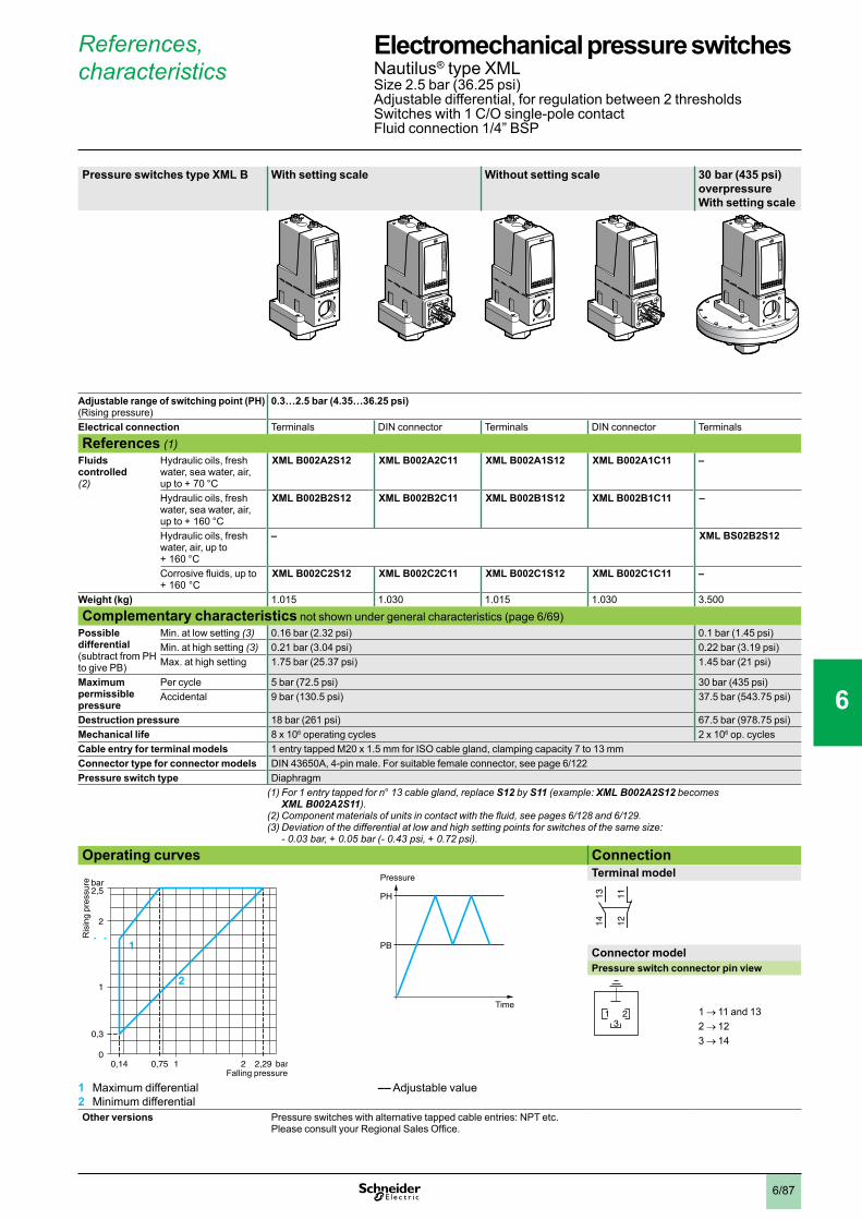
6/87
References, characteristics
Pressure switches type XML B With setting scale Without setting scale 30 bar (435 psi) overpressure With setting scale
Adjustable range of switching point (PH) (Rising pressure)
0.3…2.5 bar (4.35…36.25 psi)
Electrical connection Terminals DIN connector Terminals DIN connector Terminals
References (1)Fluids controlled (2)
Hydraulic oils, fresh water, sea water, air, up to + 70 °C
XML B002A2S12 XML B002A2C11 XML B002A1S12 XML B002A1C11 –
Hydraulic oils, fresh water, sea water, air, up to + 160 °C
XML B002B2S12 XML B002B2C11 XML B002B1S12 XML B002B1C11 –
Hydraulic oils, fresh water, air, up to + 160 °C
– XML BS02B2S12
Corrosive fluids, up to + 160 °C
XML B002C2S12 XML B002C2C11 XML B002C1S12 XML B002C1C11 –
Weight (kg) 1.015 1.030 1.015 1.030 3.500
Complementary characteristics not shown under general characteristics (page 6/69)Possible differential (subtract from PH to give PB)
Min. at low setting (3) 0.16 bar (2.32 psi) 0.1 bar (1.45 psi)Min. at high setting (3) 0.21 bar (3.04 psi) 0.22 bar (3.19 psi)Max. at high setting 1.75 bar (25.37 psi) 1.45 bar (21 psi)
Maximum permissible pressure
Per cycle 5 bar (72.5 psi) 30 bar (435 psi)Accidental 9 bar (130.5 psi) 37.5 bar (543.75 psi)
Destruction pressure 18 bar (261 psi) 67.5 bar (978.75 psi)Mechanical life 8 x 10⁶ operating cycles 2 x 10⁶ op. cyclesCable entry for terminal models 1 entry tapped M20 x 1.5 mm for ISO cable gland, clamping capacity 7 to 13 mmConnector type for connector models DIN 43650A, 4-pin male. For suitable female connector, see page 6/122Pressure switch type Diaphragm (1) For 1 entry tapped for n° 13 cable gland, replace S12 by S11 (example: XML B002A2S12 becomes
XML B002A2S11).(2)Componentmaterialsofunitsincontactwiththefluid,seepages6/128 and 6/129.(3)Deviationofthedifferentialatlowandhighsettingpointsforswitchesofthesamesize:
- 0.03 bar, + 0.05 bar (- 0.43 psi, + 0.72 psi).
Operating curves ConnectionTerminal model
Connector modelPressure switch connector pin view
1 → 11 and 132 → 123 → 14
1 Maximum differential2 Minimum differential
–– Adjustable value
Other versions Pressure switches with alternative tapped cable entries: NPT etc. Please consult your Regional Sales Office.
0,140
0,3
2 2,29
2
2,5
1
1
bar
bar
0,75
2
1
Ris
ing
pres
sure
Falling pressure
PH
PB
Time
Pressure
1314 12
11
321
Electromechanical pressure switches 0 Nautilus® type XMLSize 2.5 bar (36.25 psi)Adjustable differential, for regulation between 2 thresholdsSwitches with 1 C/O single-pole contactFluid connection 1/4” BSP
1
2
3
4
5
6
7
8
9
10
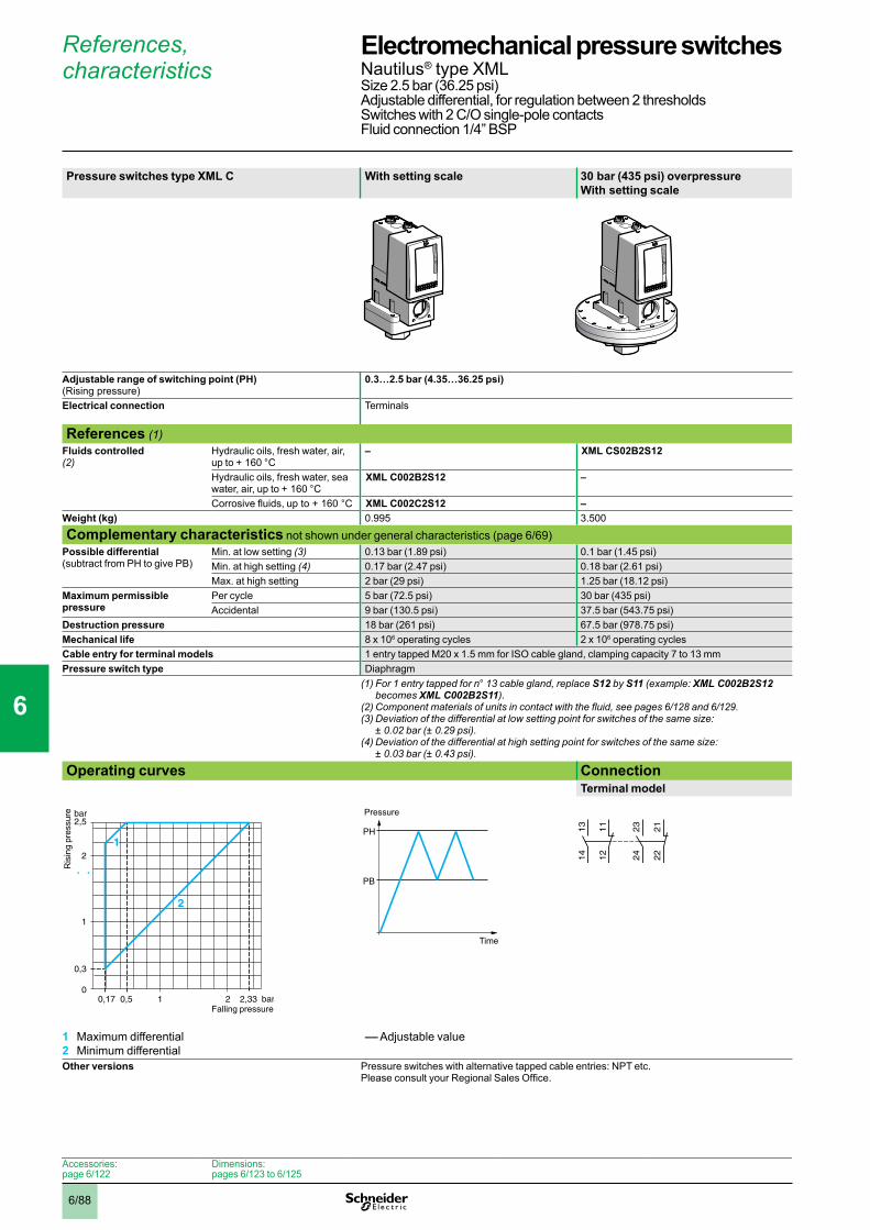
6/88
References, characteristics
Pressure switches type XML C With setting scale 30 bar (435 psi) overpressure With setting scale
Adjustable range of switching point (PH) (Rising pressure)
0.3…2.5 bar (4.35…36.25 psi)
Electrical connection Terminals
References (1)Fluids controlled (2)
Hydraulic oils, fresh water, air, up to + 160 °C
– XML CS02B2S12
Hydraulic oils, fresh water, sea water, air, up to + 160 °C
XML C002B2S12 –
Corrosive fluids, up to + 160 °C XML C002C2S12 –Weight (kg) 0.995 3.500
Complementary characteristics not shown under general characteristics (page 6/69)Possible differential (subtract from PH to give PB)
Min. at low setting (3) 0.13 bar (1.89 psi) 0.1 bar (1.45 psi)Min. at high setting (4) 0.17 bar (2.47 psi) 0.18 bar (2.61 psi)Max. at high setting 2 bar (29 psi) 1.25 bar (18.12 psi)
Maximum permissible pressure
Per cycle 5 bar (72.5 psi) 30 bar (435 psi)Accidental 9 bar (130.5 psi) 37.5 bar (543.75 psi)
Destruction pressure 18 bar (261 psi) 67.5 bar (978.75 psi)Mechanical life 8 x 10⁶ operating cycles 2 x 10⁶ operating cyclesCable entry for terminal models 1 entry tapped M20 x 1.5 mm for ISO cable gland, clamping capacity 7 to 13 mmPressure switch type Diaphragm
(1) For 1 entry tapped for n° 13 cable gland, replace S12 by S11 (example: XML C002B2S12 becomes XML C002B2S11).
(2)Componentmaterialsofunitsincontactwiththefluid,seepages6/128 and 6/129.(3)Deviationofthedifferentialatlowsettingpointforswitchesofthesamesize:
± 0.02 bar (± 0.29 psi). (4)Deviationofthedifferentialathighsettingpointforswitchesofthesamesize:
± 0.03 bar (± 0.43 psi). Operating curves Connection
Terminal model
1 Maximum differential2 Minimum differential
–– Adjustable value
Other versions Pressure switches with alternative tapped cable entries: NPT etc. Please consult your Regional Sales Office.
0,17 0,50
0,3
2 2,33
2
2,5
1
1
bar
bar
2
1
Ris
ing
pres
sure
Falling pressure
PH
PB
Time
Pressure
23
24
22
21
13
14
12
11
Accessories:page 6/122
Dimensions:pages 6/123 to 6/125
Electromechanical pressure switches 0 Nautilus® type XMLSize 2.5 bar (36.25 psi)Adjustable differential, for regulation between 2 thresholdsSwitches with 2 C/O single-pole contactsFluid connection 1/4” BSP
1
2
3
4
5
6
7
8
9
10
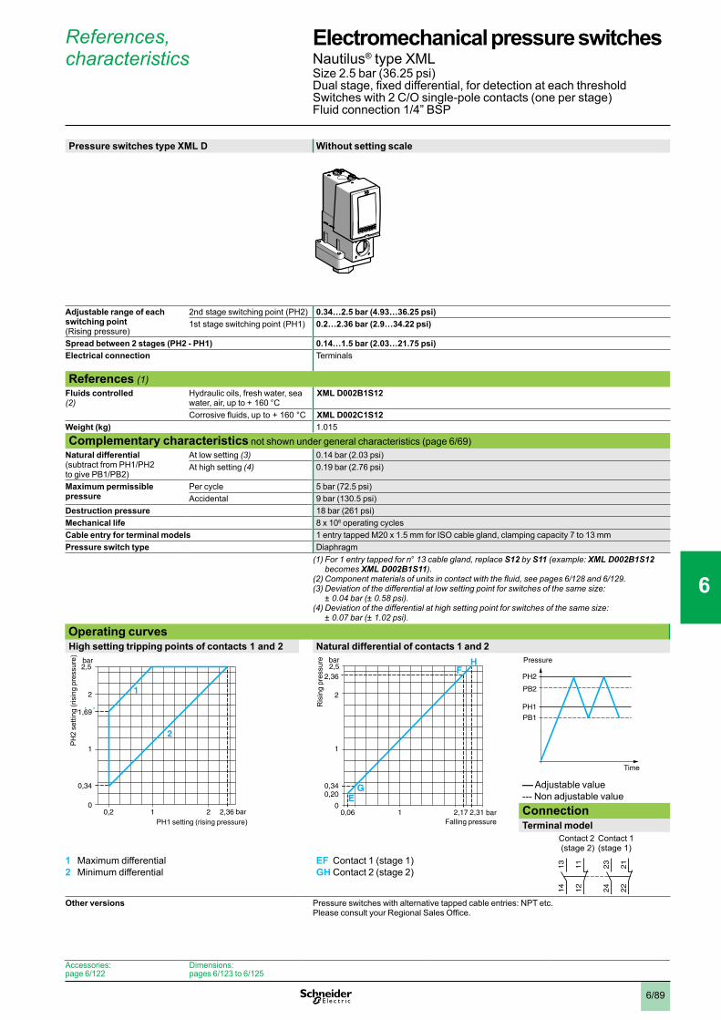
6/89
References, characteristics
Pressure switches type XML D Without setting scale
Adjustable range of each switching point (Rising pressure)
2nd stage switching point (PH2) 0.34…2.5 bar (4.93…36.25 psi) 1st stage switching point (PH1) 0.2…2.36 bar (2.9…34.22 psi)
Spread between 2 stages (PH2 - PH1) 0.14…1.5 bar (2.03…21.75 psi) Electrical connection Terminals
References (1)Fluids controlled (2)
Hydraulic oils, fresh water, sea water, air, up to + 160 °C
XML D002B1S12
Corrosive fluids, up to + 160 °C XML D002C1S12Weight (kg) 1.015
Complementary characteristics not shown under general characteristics (page 6/69)Natural differential (subtract from PH1/PH2 to give PB1/PB2)
At low setting (3) 0.14 bar (2.03 psi)At high setting (4) 0.19 bar (2.76 psi)
Maximum permissible pressure
Per cycle 5 bar (72.5 psi)Accidental 9 bar (130.5 psi)
Destruction pressure 18 bar (261 psi)Mechanical life 8 x 10⁶ operating cyclesCable entry for terminal models 1 entry tapped M20 x 1.5 mm for ISO cable gland, clamping capacity 7 to 13 mmPressure switch type Diaphragm
(1) For 1 entry tapped for n° 13 cable gland, replace S12 by S11 (example: XML D002B1S12 becomes XML D002B1S11).
(2)Componentmaterialsofunitsincontactwiththefluid,seepages6/128 and 6/129.(3)Deviationofthedifferentialatlowsettingpointforswitchesofthesamesize:
± 0.04 bar (± 0.58 psi). (4)Deviationofthedifferentialathighsettingpointforswitchesofthesamesize:
± 0.07 bar (± 1.02 psi). Operating curvesHigh setting tripping points of contacts 1 and 2 Natural differential of contacts 1 and 2
–– Adjustable value--- Non adjustable valueConnectionTerminal model
Contact 2 (stage 2)
Contact 1 (stage 1)
1 Maximum differential2 Minimum differential
EF Contact 1 (stage 1)GH Contact 2 (stage 2)
Other versions Pressure switches with alternative tapped cable entries: NPT etc. Please consult your Regional Sales Office.
0,20
0,34
2 2,36
2
2,5
1
1
1,69
bar
bar
2
1
PH
2 se
tting
(ris
ing
pres
sure
)
PH1 setting (rising pressure)0,06
0
0,200,34
2,17 2,31
2
2,52,36
1
1
bar
bar HF
GE
Ris
ing
pres
sure
Falling pressure
PH2
PH1
PB1
PB2
Time
Pressure
23
24
22
21
13
14
12
11
Accessories:page 6/122
Dimensions:pages 6/123 to 6/125
Electromechanical pressure switches 0 Nautilus® type XMLSize 2.5 bar (36.25 psi)Dual stage, fixed differential, for detection at each thresholdSwitches with 2 C/O single-pole contacts (one per stage)Fluid connection 1/4” BSP
1
2
3
4
5
6
7
8
9
10
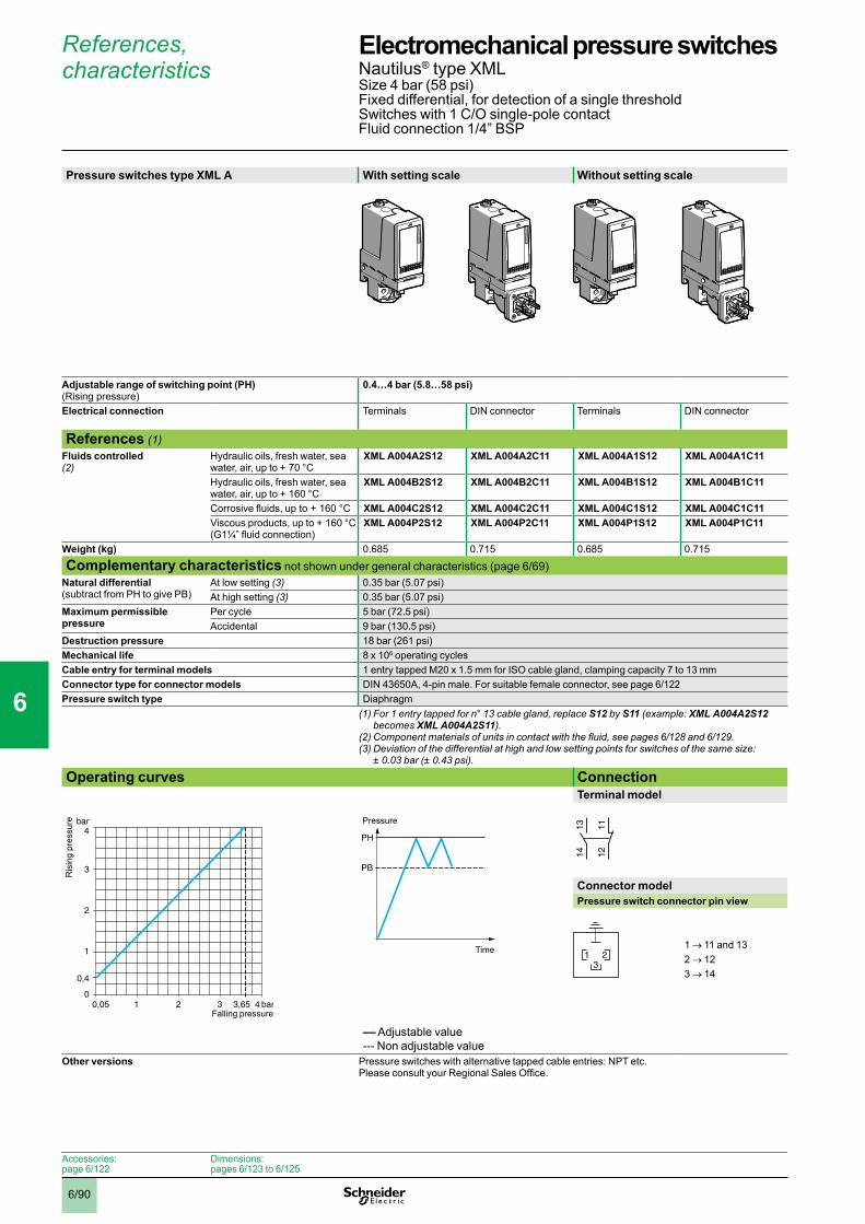
6/90
References, characteristics
Pressure switches type XML A With setting scale Without setting scale
Adjustable range of switching point (PH) (Rising pressure)
0.4…4 bar (5.8…58 psi)
Electrical connection Terminals DIN connector Terminals DIN connector
References (1)Fluids controlled (2)
Hydraulic oils, fresh water, sea water, air, up to + 70 °C
XML A004A2S12 XML A004A2C11 XML A004A1S12 XML A004A1C11
Hydraulic oils, fresh water, sea water, air, up to + 160 °C
XML A004B2S12 XML A004B2C11 XML A004B1S12 XML A004B1C11
Corrosive fluids, up to + 160 °C XML A004C2S12 XML A004C2C11 XML A004C1S12 XML A004C1C11Viscous products, up to + 160 °C(G1¼” fluid connection)
XML A004P2S12 XML A004P2C11 XML A004P1S12 XML A004P1C11
Weight (kg) 0.685 0.715 0.685 0.715
Complementary characteristics not shown under general characteristics (page 6/69)Natural differential (subtract from PH to give PB)
At low setting (3) 0.35 bar (5.07 psi)At high setting (3) 0.35 bar (5.07 psi)
Maximum permissible pressure
Per cycle 5 bar (72.5 psi)Accidental 9 bar (130.5 psi)
Destruction pressure 18 bar (261 psi)Mechanical life 8 x 10⁶ operating cyclesCable entry for terminal models 1 entry tapped M20 x 1.5 mm for ISO cable gland, clamping capacity 7 to 13 mmConnector type for connector models DIN 43650A, 4-pin male. For suitable female connector, see page 6/122Pressure switch type Diaphragm
(1) For 1 entry tapped for n° 13 cable gland, replace S12 by S11 (example: XML A004A2S12 becomes XML A004A2S11).
(2)Componentmaterialsofunitsincontactwiththefluid,seepages6/128 and 6/129.(3)Deviationofthedifferentialathighandlowsettingpointsforswitchesofthesamesize:
± 0.03 bar (± 0.43 psi). Operating curves Connection
Terminal model
Connector modelPressure switch connector pin view
1 → 11 and 132 → 123 → 14
–– Adjustable value--- Non adjustable value
Other versions Pressure switches with alternative tapped cable entries: NPT etc. Please consult your Regional Sales Office.
0,05 bar
bar
01 2 4
1
2
3
0,4
3 3,65
4
Ris
ing
pres
sure
Falling pressure
PH
PB
Time
Pressure
1314 12
11
321
Accessories:page 6/122
Dimensions:pages 6/123 to 6/125
Electromechanical pressure switches 0 Nautilus® type XMLSize 4 bar (58 psi)Fixed differential, for detection of a single thresholdSwitches with 1 C/O single-pole contactFluid connection 1/4” BSP
1
2
3
4
5
6
7
8
9
10
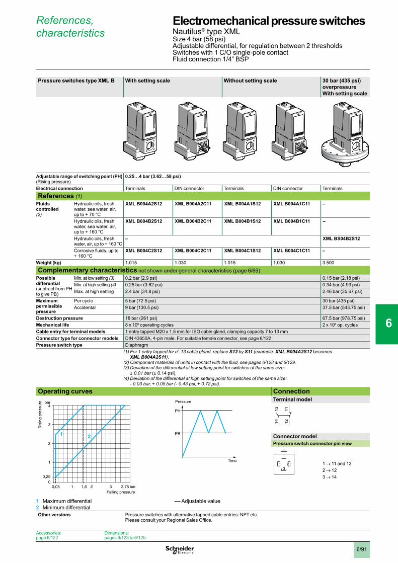
6/91
References, characteristics
Pressure switches type XML B With setting scale Without setting scale 30 bar (435 psi) overpressure With setting scale
Adjustable range of switching point (PH) (Rising pressure)
0.25…4 bar (3.62…58 psi)
Electrical connection Terminals DIN connector Terminals DIN connector Terminals
References (1)Fluids controlled (2)
Hydraulic oils, fresh water, sea water, air, up to + 70 °C
XML B004A2S12 XML B004A2C11 XML B004A1S12 XML B004A1C11 –
Hydraulic oils, fresh water, sea water, air, up to + 160 °C
XML B004B2S12 XML B004B2C11 XML B004B1S12 XML B004B1C11 –
Hydraulic oils, freshwater, air, up to + 160 °C
– XML BS04B2S12
Corrosive fluids, up to + 160 °C
XML B004C2S12 XML B004C2C11 XML B004C1S12 XML B004C1C11 –
Weight (kg) 1.015 1.030 1.015 1.030 3.500
Complementary characteristics not shown under general characteristics (page 6/69)Possible differential (subtract from PH to give PB)
Min. at low setting (3) 0.2 bar (2.9 psi) 0.15 bar (2.18 psi)Min. at high setting (4) 0.25 bar (3.62 psi) 0.34 bar (4.93 psi)Max. at high setting 2.4 bar (34.8 psi) 2.46 bar (35.67 psi)
Maximum permissible pressure
Per cycle 5 bar (72.5 psi) 30 bar (435 psi)Accidental 9 bar (130.5 psi) 37.5 bar (543.75 psi)
Destruction pressure 18 bar (261 psi) 67.5 bar (978.75 psi)Mechanical life 8 x 10⁶ operating cycles 2 x 10⁶ op. cyclesCable entry for terminal models 1 entry tapped M20 x 1.5 mm for ISO cable gland, clamping capacity 7 to 13 mmConnector type for connector models DIN 43650A, 4-pin male. For suitable female connector, see page 6/122Pressure switch type Diaphragm (1) For 1 entry tapped for n° 13 cable gland, replace S12 by S11 (example: XML B004A2S12 becomes
XML B004A2S11).(2)Componentmaterialsofunitsincontactwiththefluid,seepages6/128 and 6/129.(3)Deviationofthedifferentialatlowsettingpointforswitchesofthesamesize:
± 0.01 bar (± 0.14 psi).(4)Deviationofthedifferentialathighsettingpointforswitchesofthesamesize:
- 0.03 bar, + 0.05 bar (- 0.43 psi, + 0.72 psi).
Operating curves ConnectionTerminal model
Connector modelPressure switch connector pin view
1 → 11 and 132 → 123 → 14
1 Maximum differential2 Minimum differential
–– Adjustable value
Other versions Pressure switches with alternative tapped cable entries: NPT etc. Please consult your Regional Sales Office.
0,05 bar
bar
01 21,6
1
2
3
0,25
3 3,75
4
1 2
Ris
ing
pres
sure
Falling pressure
PH
PB
Time
Pressure
1314 12
11
321
Accessories:page 6/122
Dimensions:pages 6/123 to 6/125
Electromechanical pressure switches 0 Nautilus® type XMLSize 4 bar (58 psi)Adjustable differential, for regulation between 2 thresholdsSwitches with 1 C/O single-pole contactFluid connection 1/4” BSP
1
2
3
4
5
6
7
8
9
10

6/92
References, characteristics
Pressure switches type XML C With setting scale 30 bar (435 psi) overpressure With setting scale
Adjustable range of switching point (PH) (Rising pressure)
0.3…4 bar (4.35…58 psi)
Electrical connection Terminals
References (1)Fluids controlled (2)
Hydraulic oils, fresh water, air, up to + 160 °C
– XML CS04B2S12
Hydraulic oils, fresh water, sea water, air, up to + 160 °C
XML C004B2S12 –
Corrosive fluids, up to + 160 °C XML C004C2S12 –Weight (kg) 0.685 3.500
Complementary characteristics not shown under general characteristics (page 6/69)Possible differential (subtract from PH to give PB)
Min. at low setting (3) 0.15 bar (2.18 psi) 0.1 bar (1.45 psi)Min. at high setting (3) 0.17 bar (2.47 psi) 0.25 bar (3.62 psi)Max. at high setting 2.5 bar (36.25 psi) 2.20 bar (31.9 psi)
Maximum permissible pressure
Per cycle 5 bar (72.5 psi) 30 bar (435 psi)Accidental 9 bar (130.5 psi) 37.5 bar (543.75 psi)
Destruction pressure 18 bar (261 psi) 67.5 bar (978.75 psi)Mechanical life 8 x 10⁶ operating cycles 2 x 10⁶ operating cyclesCable entry for terminal models 1 entry tapped M20 x 1.5 mm for ISO cable gland, clamping capacity 7 to 13 mmPressure switch type Diaphragm
(1) For 1 entry tapped for n° 13 cable gland, replace S12 by S11 (example: XML C004B2S12 becomes XML C004B2S11).
(2)Componentmaterialsofunitsincontactwiththefluid,seepages6/128 and 6/129.(3)Deviationofthedifferentialathighandlowsettingpointsforswitchesofthesamesize:
± 0.02 bar (± 0.29 psi). Operating curves Connection
Terminal model
1 Maximum differential2 Minimum differential
–– Adjustable value
Other versions Pressure switches with alternative tapped cable entries: NPT etc. Please consult your Regional Sales Office.
0,15 bar
bar
01 21,5
1
2
3
0,3
3 3,83
4
1
2
Ris
ing
pres
sure
Falling pressure
PH
PB
Time
Pressure
23
24
22
21
13
14
12
11
Accessories:page 6/122
Dimensions:pages 6/123 to 6/125
Electromechanical pressure switches 0 Nautilus® type XMLSize 4 bar (58 psi)Adjustable differential, for regulation between 2 thresholdsSwitches with 2 C/O single-pole contactsFluid connection 1/4” BSP
1
2
3
4
5
6
7
8
9
10
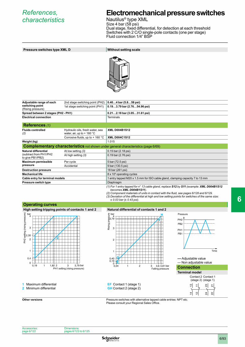
6/93
References, characteristics
Pressure switches type XML D Without setting scale
Adjustable range of each switching point (Rising pressure)
2nd stage switching point (PH2) 0.40…4 bar (5.8…58 psi) 1st stage switching point (PH1) 0.19…3.79 bar (2.76…54.96 psi)
Spread between 2 stages (PH2 - PH1) 0.21…2.18 bar (3.05…31.61 psi) Electrical connection Terminals
References (1)Fluids controlled (2)
Hydraulic oils, fresh water, sea water, air, up to + 160 °C
XML D004B1S12
Corrosive fluids, up to + 160 °C XML D004C1S12Weight (kg) 1.015
Complementary characteristics not shown under general characteristics (page 6/69)Natural differential (subtract from PH1/PH2 to give PB1/PB2)
At low setting (3) 0.15 bar (2.18 psi)At high setting (3) 0.19 bar (2.76 psi)
Maximum permissible pressure
Per cycle 5 bar (72.5 psi)Accidental 9 bar (130.5 psi)
Destruction pressure 18 bar (261 psi)Mechanical life 8 x 10⁶ operating cyclesCable entry for terminal models 1 entry tapped M20 x 1.5 mm for ISO cable gland, clamping capacity 7 to 13 mmPressure switch type Diaphragm
(1) For 1 entry tapped for n° 13 cable gland, replace S12 by S11 (example: XML D004B1S12 becomes XML D004B1S11).
(2)Componentmaterialsofunitsincontactwiththefluid,seepages6/128 and 6/129.(3)Deviationofthedifferentialathighandlowsettingpointsforswitchesofthesamesize:
± 0.03 bar (± 0.43 psi). Operating curvesHigh setting tripping points of contacts 1 and 2 Natural differential of contacts 1 and 2
–– Adjustable value--- Non adjustable valueConnectionTerminal model
Contact 2 (stage 2)
Contact 1 (stage 1)
1 Maximum differential2 Minimum differential
EF Contact 1 (stage 1)GH Contact 2 (stage 2)
Other versions Pressure switches with alternative tapped cable entries: NPT etc. Please consult your Regional Sales Office.
0,19 bar
bar
01 21,82
1
2
2,35
3
0,4
3 3,79
4
1
2
PH
2 se
tting
(ris
ing
pres
sure
)
PH1 setting (rising pressure)0,04 bar
bar
01 2
1
2
3
0,190,40
3 3,6 3,81
43,79
E
G
H
F
Ris
ing
pres
sure
Falling pressure
PH2
PH1
PB1
PB2
Time
Pressure
23
24
22
21
13
14
12
11
Accessories:page 6/122
Dimensions:pages 6/123 to 6/125
Electromechanical pressure switches 0 Nautilus® type XMLSize 4 bar (58 psi)Dual stage, fixed differential, for detection at each thresholdSwitches with 2 C/O single-pole contacts (one per stage)Fluid connection 1/4” BSP
1
2
3
4
5
6
7
8
9
10
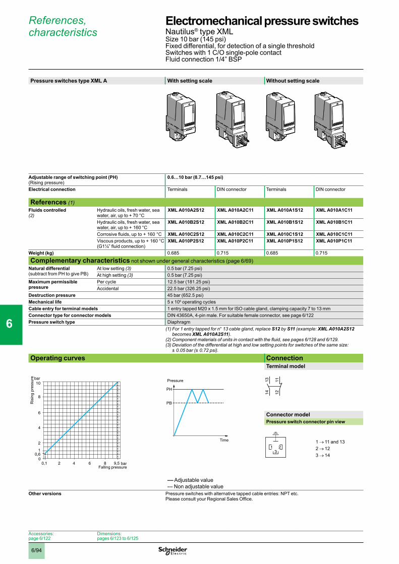
6/94
References, characteristics
Pressure switches type XML A With setting scale Without setting scale
Adjustable range of switching point (PH) (Rising pressure)
0.6…10 bar (8.7…145 psi)
Electrical connection Terminals DIN connector Terminals DIN connector
References (1)Fluids controlled (2)
Hydraulic oils, fresh water, sea water, air, up to + 70 °C
XML A010A2S12 XML A010A2C11 XML A010A1S12 XML A010A1C11
Hydraulic oils, fresh water, sea water, air, up to + 160 °C
XML A010B2S12 XML A010B2C11 XML A010B1S12 XML A010B1C11
Corrosive fluids, up to + 160 °C XML A010C2S12 XML A010C2C11 XML A010C1S12 XML A010C1C11Viscous products, up to + 160 °C(G1¼” fluid connection)
XML A010P2S12 XML A010P2C11 XML A010P1S12 XML A010P1C11
Weight (kg) 0.685 0.715 0.685 0.715
Complementary characteristics not shown under general characteristics (page 6/69)Natural differential (subtract from PH to give PB)
At low setting (3) 0.5 bar (7.25 psi)At high setting (3) 0.5 bar (7.25 psi)
Maximum permissible pressure
Per cycle 12.5 bar (181.25 psi)Accidental 22.5 bar (326.25 psi)
Destruction pressure 45 bar (652.5 psi)Mechanical life 5 x 10⁶ operating cyclesCable entry for terminal models 1 entry tapped M20 x 1.5 mm for ISO cable gland, clamping capacity 7 to 13 mmConnector type for connector models DIN 43650A, 4-pin male. For suitable female connector, see page 6/122Pressure switch type Diaphragm
(1) For 1 entry tapped for n° 13 cable gland, replace S12 by S11 (example: XML A010A2S12 becomes XML A010A2S11).
(2)Componentmaterialsofunitsincontactwiththefluid,seepages6/128 and 6/129.(3)Deviationofthedifferentialathighandlowsettingpointsforswitchesofthesamesize:
± 0.05 bar (± 0.72 psi). Operating curves Connection
Terminal model
Connector modelPressure switch connector pin view
1 → 11 and 132 → 123 → 14
–– Adjustable value--- Non adjustable value
Other versions Pressure switches with alternative tapped cable entries: NPT etc. Please consult your Regional Sales Office.
bar
bar
0
8
6
4
2
10,6
10
9,586420,1
Ris
ing
pres
sure
Falling pressure
PH
PB
Time
Pressure 1314 12
11
321
Accessories:page 6/122
Dimensions:pages 6/123 to 6/125
Electromechanical pressure switches 0 Nautilus® type XMLSize 10 bar (145 psi)Fixed differential, for detection of a single thresholdSwitches with 1 C/O single-pole contactFluid connection 1/4” BSP
1
2
3
4
5
6
7
8
9
10

6/95
References, characteristics
Pressure switches type XML B With setting scale Without setting scale 30 bar (435 psi) overpressure With setting scale
Adjustable range of switching point (PH) (Rising pressure)
0.7…10 bar (10.15…145 psi)
Electrical connection Terminals DIN connector Terminals DIN connector Terminals
References (1)Fluids controlled (2)
Hydraulic oils, fresh water, sea water, air, up to + 70 °C
XML B010A2S12 XML B010A2C11 XML B010A1S12 XML B010A1C11 –
Hydraulic oils, freshwater, air, up to + 160 °C
– – – – XML BS10A2S12
Hydraulic oils, freshwater, air, up to + 160 °C
XML B010B2S12 XML B010B2C11 XML B010B1S12 XML B010B1C11 –
Corrosive fluids, up to + 160 °C
XML B010C2S12 XML B010C2C11 XML B010C1S12 XML B010C1C11 –
Viscous products, up to + 160 °C(G1¼” fluid connection)
XML B010P2S12 XML B010P2C11 XML B010P1S12 XML B010P1C11 –
Weight (kg) 0.705 0.735 0.705 0.735 3.500
Complementary characteristics not shown under general characteristics (page 6/69)Possible differential (subtract from PH to give PB)
Min. at low setting (3) 0.57 bar (8.26 psi) 0.45 bar (6.52 psi)Min. at high setting (4) 0.85 bar (12.32 psi) 0.85 bar (12.32 psi)Max. at high setting 7.5 bar (108.75 psi) 6.25 bar (90.62 psi)
Maximum permissible pressure
Per cycle 12.5 bar (181.25 psi) 30 bar (435 psi)Accidental 22.5 bar (326.25 psi) 37.5 bar (543.75 psi)
Destruction pressure 45 bar (652.5 psi) 67.5 bar (978.75 psi)Mechanical life 5 x 10⁶ operating cycles 2 x 10⁶ op. cyclesCable entry for terminal models 1 entry tapped M20 x 1.5 mm for ISO cable gland, clamping capacity 7 to 13 mmConnector type for connector models DIN 43650A, 4-pin male. For suitable female connector, see page 6/122Pressure switch type Diaphragm (1) For 1 entry tapped for n° 13 cable gland, replace S12 by S11 (example: XML B010A2S12 becomes
XML B010A2S11).(2)Componentmaterialsofunitsincontactwiththefluid,seepages6/128 and 6/129.(3)Deviationofthedifferentialatlowsettingpointforswitchesofthesamesize:
± 0.05 bar (± 0.72 psi).(4)Deviationofthedifferentialathighsettingpointforswitchesofthesamesize:
- 0.1 bar, + 0.15 bar (- 1.45 psi, + 2.17 psi).
Operating curves ConnectionTerminal model
Connector modelPressure switch connector pin view
1 → 11 and 132 → 123 → 14
1 Maximum differential2 Minimum differential
–– Adjustable value
Other versions Pressure switches with alternative tapped cable entries: NPT etc. Please consult your Regional Sales Office.
bar
bar
0
8
6
4
2
0,7
10
9,158642,50,13
2
1Ris
ing
pres
sure
Falling pressure
PH
PB
Time
Pressure
1314 12
11
321
Electromechanical pressure switches 0 Nautilus® type XMLSize 10 bar (145 psi)Adjustable differential, for regulation between 2 thresholdsSwitches with 1 C/O single-pole contactFluid connection 1/4” BSP
1
2
3
4
5
6
7
8
9
10
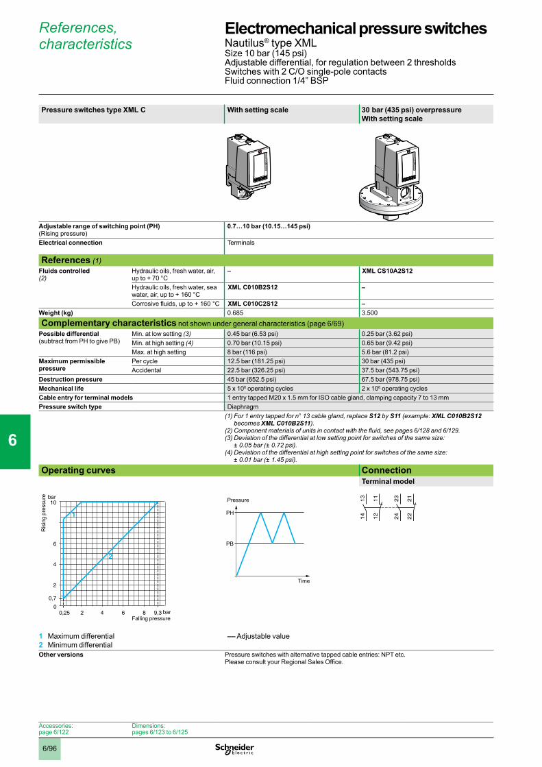
6/96
References, characteristics
Pressure switches type XML C With setting scale 30 bar (435 psi) overpressure With setting scale
Adjustable range of switching point (PH) (Rising pressure)
0.7…10 bar (10.15…145 psi)
Electrical connection Terminals
References (1)Fluids controlled (2)
Hydraulic oils, fresh water, air, up to + 70 °C
– XML CS10A2S12
Hydraulic oils, fresh water, sea water, air, up to + 160 °C
XML C010B2S12 –
Corrosive fluids, up to + 160 °C XML C010C2S12 –Weight (kg) 0.685 3.500
Complementary characteristics not shown under general characteristics (page 6/69)Possible differential (subtract from PH to give PB)
Min. at low setting (3) 0.45 bar (6.53 psi) 0.25 bar (3.62 psi)Min. at high setting (4) 0.70 bar (10.15 psi) 0.65 bar (9.42 psi)Max. at high setting 8 bar (116 psi) 5.6 bar (81.2 psi)
Maximum permissible pressure
Per cycle 12.5 bar (181.25 psi) 30 bar (435 psi)Accidental 22.5 bar (326.25 psi) 37.5 bar (543.75 psi)
Destruction pressure 45 bar (652.5 psi) 67.5 bar (978.75 psi)Mechanical life 5 x 10⁶ operating cycles 2 x 10⁶ operating cyclesCable entry for terminal models 1 entry tapped M20 x 1.5 mm for ISO cable gland, clamping capacity 7 to 13 mmPressure switch type Diaphragm
(1) For 1 entry tapped for n° 13 cable gland, replace S12 by S11 (example: XML C010B2S12 becomes XML C010B2S11).
(2)Componentmaterialsofunitsincontactwiththefluid,seepages6/128 and 6/129.(3)Deviationofthedifferentialatlowsettingpointforswitchesofthesamesize:
± 0.05 bar (± 0.72 psi). (4)Deviationofthedifferentialathighsettingpointforswitchesofthesamesize:
± 0.01 bar (± 1.45 psi). Operating curves Connection
Terminal model
1 Maximum differential2 Minimum differential
–– Adjustable value
Other versions Pressure switches with alternative tapped cable entries: NPT etc. Please consult your Regional Sales Office.
bar
bar
0
6
4
2
0,7
10
9,386420,25
2
1
Ris
ing
pres
sure
Falling pressure
PH
PB
Time
Pressure 23
24
22
21
13
14
12
11
Accessories:page 6/122
Dimensions:pages 6/123 to 6/125
Electromechanical pressure switches 0 Nautilus® type XMLSize 10 bar (145 psi)Adjustable differential, for regulation between 2 thresholdsSwitches with 2 C/O single-pole contactsFluid connection 1/4” BSP
1
2
3
4
5
6
7
8
9
10

6/97
References, characteristics
Pressure switches type XML D Without setting scale
Adjustable range of each switching point (Rising pressure)
2nd stage switching point (PH2) 1.2…10 bar (17.4…145 psi) 1st stage switching point (PH1) 0.52…9.32 bar (7.54…135.14 psi)
Spread between 2 stages (PH2 - PH1) 0.68…5.8 bar (9.86…84.1 psi) Electrical connection Terminals
References (1)Fluids controlled (2)
Hydraulic oils, fresh water, sea water, air, up to + 160 °C
XML D010B1S12
Corrosive fluids, up to + 160 °C XML D010C1S12Weight (kg) 0.705
Complementary characteristics not shown under general characteristics (page 6/69)Natural differential (subtract from PH1/PH2 to give PB1/PB2)
At low setting (3) 0.45 bar (6.53 psi)At high setting (4) 0.6 bar (8.7 psi)
Maximum permissible pressure
Per cycle 12.5 bar (181.25 psi)Accidental 22.5 bar (326.25 psi)
Destruction pressure 45 bar (652.5 psi)Mechanical life 5 x 10⁶ operating cyclesCable entry for terminal models 1 entry tapped M20 x 1.5 mm for ISO cable gland, clamping capacity 7 to 13 mmPressure switch type Diaphragm
(1) For 1 entry tapped for n° 13 cable gland, replace S12 by S11 (example: XML D010B1S12 becomes XML D010B1S11).
(2)Componentmaterialsofunitsincontactwiththefluid,seepages6/128 and 6/129.(3)Deviationofthedifferentialatlowsettingpointforswitchesofthesamesize:
± 0.05 bar (± 0.72 psi). (4)Deviationofthedifferentialathighsettingpointforswitchesofthesamesize:
± 0.1 bar (± 1.45 psi). Operating curvesHigh setting tripping points of contacts 1 and 2 Natural differential of contacts 1 and 2
–– Adjustable value--- Non adjustable valueConnectionTerminal model
Contact 2 (stage 2)
Contact 1 (stage 1)
1 Maximum differential2 Minimum differential
EF Contact 1 (stage 1)GH Contact 2 (stage 2)
Other versions Pressure switches with alternative tapped cable entries: NPT etc. Please consult your Regional Sales Office.
bar
bar
0
8
66,34
4
2
1,2
10
9,32864,220,52
2
1
PH
2 se
tting
(ris
ing
pres
sure
)
PH1 setting (rising pressure)
bar
bar
0
8
9,32
6
4
2
0,521,2
10
9,48,726420,07 0,75
H
F
G
E
Ris
ing
pres
sure
Falling pressure
PH2
PH1
PB1
PB2
Time
Pressure
23
24
22
21
13
14
12
11
Accessories:page 6/122
Dimensions:pages 6/123 to 6/125
Electromechanical pressure switches 0 Nautilus® type XMLSize 10 bar (145 psi)Dual stage, fixed differential, for detection at each thresholdSwitches with 2 C/O single-pole contacts (one per stage)Fluid connection 1/4” BSP
1
2
3
4
5
6
7
8
9
10
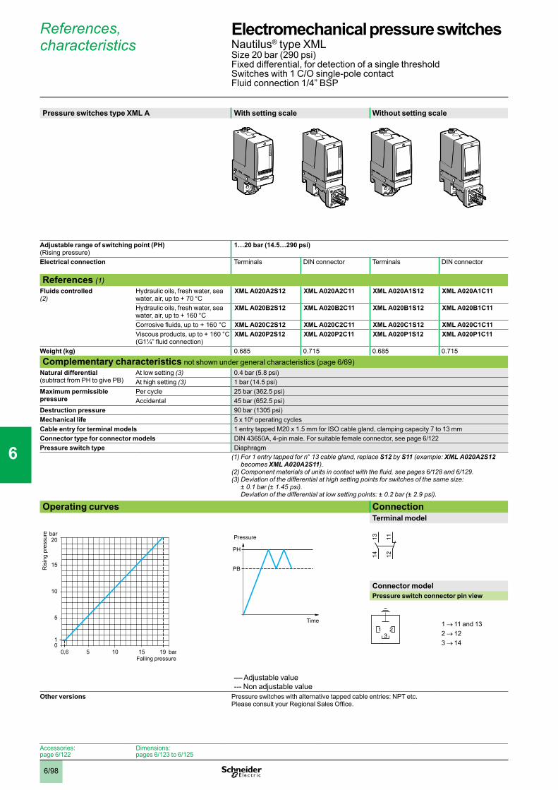
6/98
References, characteristics
Pressure switches type XML A With setting scale Without setting scale
Adjustable range of switching point (PH) (Rising pressure)
1…20 bar (14.5…290 psi)
Electrical connection Terminals DIN connector Terminals DIN connector
References (1)Fluids controlled (2)
Hydraulic oils, fresh water, sea water, air, up to + 70 °C
XML A020A2S12 XML A020A2C11 XML A020A1S12 XML A020A1C11
Hydraulic oils, fresh water, sea water, air, up to + 160 °C
XML A020B2S12 XML A020B2C11 XML A020B1S12 XML A020B1C11
Corrosive fluids, up to + 160 °C XML A020C2S12 XML A020C2C11 XML A020C1S12 XML A020C1C11Viscous products, up to + 160 °C(G1¼” fluid connection)
XML A020P2S12 XML A020P2C11 XML A020P1S12 XML A020P1C11
Weight (kg) 0.685 0.715 0.685 0.715
Complementary characteristics not shown under general characteristics (page 6/69)Natural differential (subtract from PH to give PB)
At low setting (3) 0.4 bar (5.8 psi)At high setting (3) 1 bar (14.5 psi)
Maximum permissible pressure
Per cycle 25 bar (362.5 psi)Accidental 45 bar (652.5 psi)
Destruction pressure 90 bar (1305 psi)Mechanical life 5 x 10⁶ operating cyclesCable entry for terminal models 1 entry tapped M20 x 1.5 mm for ISO cable gland, clamping capacity 7 to 13 mmConnector type for connector models DIN 43650A, 4-pin male. For suitable female connector, see page 6/122Pressure switch type Diaphragm
(1) For 1 entry tapped for n° 13 cable gland, replace S12 by S11 (example: XML A020A2S12 becomes XML A020A2S11).
(2)Componentmaterialsofunitsincontactwiththefluid,seepages6/128 and 6/129.(3)Deviationofthedifferentialathighsettingpointsforswitchesofthesamesize:
± 0.1 bar (± 1.45 psi). Deviationofthedifferentialatlowsettingpoints:±0.2bar(±2.9psi).
Operating curves ConnectionTerminal model
Connector modelPressure switch connector pin view
1 → 11 and 132 → 123 → 14
–– Adjustable value--- Non adjustable value
Other versions Pressure switches with alternative tapped cable entries: NPT etc. Please consult your Regional Sales Office.
0,6 bar
bar
05 10
5
10
15
1
15 19
20
Ris
ing
pres
sure
Falling pressure
PH
PB
Time
Pressure 1314 12
11
321
Accessories:page 6/122
Dimensions:pages 6/123 to 6/125
Electromechanical pressure switches 0 Nautilus® type XMLSize 20 bar (290 psi)Fixed differential, for detection of a single thresholdSwitches with 1 C/O single-pole contactFluid connection 1/4” BSP
1
2
3
4
5
6
7
8
9
10

6/99
References, characteristics
Pressure switches type XML B With setting scale Without setting scale 30 bar (435 psi) overpressure With setting scale
Adjustable range of switching point (PH) (Rising pressure)
1.3…20 bar (18.9…290 psi)
Electrical connection Terminals DIN connector Terminals DIN connector Terminals
References (1)Fluids controlled (2)
Hydraulic oils, fresh water, sea water, air, up to + 70 °C
XML B020A2S12 XML B020A2C11 XML B020A1S12 XML B020A1C11 –
Hydraulic oils, freshwater, air, up to + 160 °C
– – – – XML BS20A2S12
Hydraulic oils, freshwater, air, up to + 160 °C
XML B020B2S12 XML B020B2C11 XML B020B1S12 XML B020B1C11 –
Corrosive fluids, up to + 160 °C
XML B020C2S12 XML B020C2C11 XML B020C1S12 XML B020C1C11 –
Viscous products, up to + 160 °C(G1¼” fluid connection)
XML B020P2S12 XML B020P2C11 XML B020P1S12 XML B020P1C11 –
Weight (kg) 0.705 0.735 0.705 0.735 3.500
Complementary characteristics not shown under general characteristics (page 6/69)Possible differential (subtract from PH to give PB)
Min. at low setting (3) 1 bar (14.5 psi) 0.95 bar (13.78 psi)Min. at high setting (3) 1.6 bar (23.20 psi) 1.45 bar (21.03 psi)Max. at high setting 11 bar (159.5 psi) 12.6 bar (182.7 psi)
Maximum permissible pressure
Per cycle 25 bar (362.5 psi) 30 bar (435 psi)Accidental 45 bar (652.5 psi) 37.5 bar (543.75 psi)
Destruction pressure 90 bar (1305 psi) 67.5 bar (978.75 psi)Mechanical life 5 x 10⁶ operating cycles 2 x 10⁶ op. cyclesCable entry for terminal models 1 entry tapped M20 x 1.5 mm for ISO cable gland, clamping capacity 7 to 13 mmConnector type for connector models DIN 43650A, 4-pin male. For suitable female connector, see page 6/122Pressure switch type Diaphragm (1) For 1 entry tapped for n° 13 cable gland, replace S12 by S11 (example: XML B020A2S12 becomes
XML B020A2S11).(2)Componentmaterialsofunitsincontactwiththefluid,seepages6/128 and 6/129.(3)Deviationofthedifferentialathighandlowsettingpointsforswitchesofthesamesize:
± 0.25 bar (± 3.63 psi).
Operating curves ConnectionTerminal model
Connector modelPressure switch connector pin view
1 → 11 and 132 → 123 → 14
1 Maximum differential2 Minimum differential
–– Adjustable value
Other versions Pressure switches with alternative tapped cable entries: NPT etc. Please consult your Regional Sales Office.
0,3 bar
bar
05 109
5
10
15
1,3
15 18,4
20
1 2
Ris
ing
pres
sure
Falling pressure
PH
PB
Time
Pressure
1314 12
11
321
Electromechanical pressure switches 0 Nautilus® type XMLSize 20 bar (290 psi)Adjustable differential, for regulation between 2 thresholdsSwitches with 1 C/O single-pole contactFluid connection 1/4” BSP
1
2
3
4
5
6
7
8
9
10
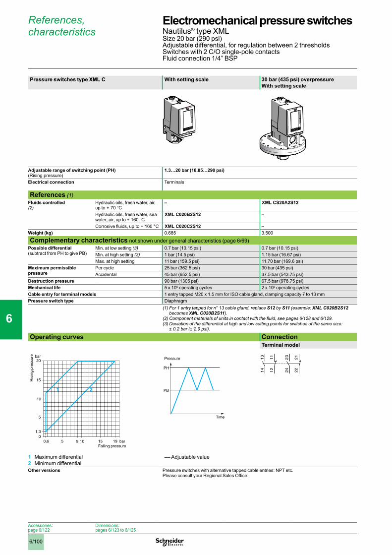
6/100
References, characteristics
Pressure switches type XML C With setting scale 30 bar (435 psi) overpressure With setting scale
Adjustable range of switching point (PH) (Rising pressure)
1.3…20 bar (18.85…290 psi)
Electrical connection Terminals
References (1)Fluids controlled (2)
Hydraulic oils, fresh water, air, up to + 70 °C
– XML CS20A2S12
Hydraulic oils, fresh water, sea water, air, up to + 160 °C
XML C020B2S12 –
Corrosive fluids, up to + 160 °C XML C020C2S12 –Weight (kg) 0.685 3.500
Complementary characteristics not shown under general characteristics (page 6/69)Possible differential (subtract from PH to give PB)
Min. at low setting (3) 0.7 bar (10.15 psi) 0.7 bar (10.15 psi)Min. at high setting (3) 1 bar (14.5 psi) 1.15 bar (16.67 psi)Max. at high setting 11 bar (159.5 psi) 11.70 bar (169.6 psi)
Maximum permissible pressure
Per cycle 25 bar (362.5 psi) 30 bar (435 psi)Accidental 45 bar (652.5 psi) 37.5 bar (543.75 psi)
Destruction pressure 90 bar (1305 psi) 67.5 bar (978.75 psi)Mechanical life 5 x 10⁶ operating cycles 2 x 10⁶ operating cyclesCable entry for terminal models 1 entry tapped M20 x 1.5 mm for ISO cable gland, clamping capacity 7 to 13 mmPressure switch type Diaphragm
(1) For 1 entry tapped for n° 13 cable gland, replace S12 by S11 (example: XML C020B2S12 becomes XML C020B2S11).
(2)Componentmaterialsofunitsincontactwiththefluid,seepages6/128 and 6/129.(3)Deviationofthedifferentialathighandlowsettingpointsforswitchesofthesamesize:
± 0.2 bar (± 2.9 psi). Operating curves Connection
Terminal model
1 Maximum differential2 Minimum differential
–– Adjustable value
Other versions Pressure switches with alternative tapped cable entries: NPT etc. Please consult your Regional Sales Office.
0,6 bar
bar
05 9 10
5
15
1,3
15 19
20
1 2
10
Ris
ing
pres
sure
Falling pressure
PH
PB
Time
Pressure 23
24
22
21
13
14
12
11
Accessories:page 6/122
Dimensions:pages 6/123 to 6/125
Electromechanical pressure switches 0 Nautilus® type XMLSize 20 bar (290 psi)Adjustable differential, for regulation between 2 thresholdsSwitches with 2 C/O single-pole contactsFluid connection 1/4” BSP
1
2
3
4
5
6
7
8
9
10
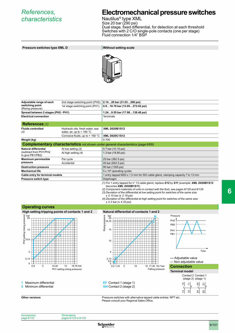
6/101
References, characteristics
Pressure switches type XML D Without setting scale
Adjustable range of each switching point (Rising pressure)
2nd stage switching point (PH2) 2.14…20 bar (31.03…290 psi) 1st stage switching point (PH1) 0.9…18.76 bar (13.05…272.02 psi)
Spread between 2 stages (PH2 - PH1) 1.24…9.55 bar (17.98…138.48 psi) Electrical connection Terminals
References (1)Fluids controlled (2)
Hydraulic oils, fresh water, sea water, air, up to + 160 °C
XML D020B1S12
Corrosive fluids, up to + 160 °C XML D020C1S12Weight (kg) 0.705
Complementary characteristics not shown under general characteristics (page 6/69)Natural differential (subtract from PH1/PH2 to give PB1/PB2)
At low setting (3) 0.7 bar (10.15 psi)At high setting (4) 1.3 bar (18.85 psi)
Maximum permissible pressure
Per cycle 25 bar (362.5 psi)Accidental 45 bar (652.5 psi)
Destruction pressure 90 bar (1305 psi)Mechanical life 5 x 10⁶ operating cyclesCable entry for terminal models 1 entry tapped M20 x 1.5 mm for ISO cable gland, clamping capacity 7 to 13 mmPressure switch type Diaphragm
(1) For 1 entry tapped for n° 13 cable gland, replace S12 by S11 (example: XML D020B1S12 becomes XML D020B1S11).
(2)Componentmaterialsofunitsincontactwiththefluid,seepages6/128 and 6/129.(3)Deviationofthedifferentialatlowsettingpointforswitchesofthesamesize:
± 0.15 bar (± 2.18 psi). (4)Deviationofthedifferentialathighsettingpointforswitchesofthesamesize:
± 0.3 bar (± 4.35 psi). Operating curvesHigh setting tripping points of contacts 1 and 2 Natural differential of contacts 1 and 2
–– Adjustable value--- Non adjustable valueConnectionTerminal model
Contact 2 (stage 2)
Contact 1 (stage 1)
1 Maximum differential2 Minimum differential
EF Contact 1 (stage 1)GH Contact 2 (stage 2)
Other versions Pressure switches with alternative tapped cable entries: NPT etc. Please consult your Regional Sales Office.
0,9 bar
bar
05 10,45
5
10,6
15
2,14
15 18,76
20
1 2
PH
2 se
tting
(ris
ing
pres
sure
)
PH1 setting (rising pressure)0,2 1,44 bar
bar
05 10
5
10
15
18,76
0,92,14
15 17,46 18,7
20
E
F
H
G
Ris
ing
pres
sure
Falling pressure
PH2
PH1
PB1
PB2
Time
Pressure
23
24
22
21
13
14
12
11
Accessories:page 6/122
Dimensions:pages 6/123 to 6/125
Electromechanical pressure switches 0 Nautilus® type XMLSize 20 bar (290 psi)Dual stage, fixed differential, for detection at each thresholdSwitches with 2 C/O single-pole contacts (one per stage)Fluid connection 1/4” BSP
1
2
3
4
5
6
7
8
9
10
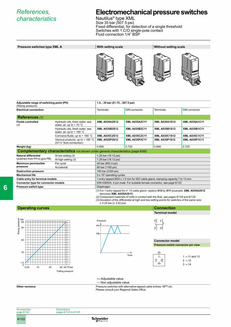
6/102
References, characteristics
Pressure switches type XML A With setting scale Without setting scale
Adjustable range of switching point (PH) (Rising pressure)
1.5…35 bar (21.75…507.5 psi)
Electrical connection Terminals DIN connector Terminals DIN connector
References (1)Fluids controlled (2)
Hydraulic oils, fresh water, sea water, air, up to + 70 °C
XML A035A2S12 XML A035A2C11 XML A035A1S12 XML A035A1C11
Hydraulic oils, fresh water, sea water, air, up to + 160 °C
XML A035B2S12 XML A035B2C11 XML A035B1S12 XML A035B1C11
Corrosive fluids, up to + 160 °C XML A035C2S12 XML A035C2C11 XML A035C1S12 XML A035C1C11Viscous products, up to + 160 °C(G1¼” fluid connection)
XML A035P2S12 XML A035P2C11 XML A035P1S12 XML A035P1C11
Weight (kg) 0.695 0.725 0.695 0.725
Complementary characteristics not shown under general characteristics (page 6/69)Natural differential (subtract from PH to give PB)
At low setting (3) 1.25 bar (18.12 psi)At high setting (3) 1.25 bar (18.12 psi)
Maximum permissible pressure
Per cycle 45 bar (652.5 psi)Accidental 80 bar (1160 psi)
Destruction pressure 160 bar (2320 psi)Mechanical life 5 x 10⁶ operating cyclesCable entry for terminal models 1 entry tapped M20 x 1.5 mm for ISO cable gland, clamping capacity 7 to 13 mmConnector type for connector models DIN 43650A, 4-pin male. For suitable female connector, see page 6/122Pressure switch type Diaphragm
(1) For 1 entry tapped for n° 13 cable gland, replace S12 by S11 (example: XML A035A2S12 becomes XML A035A2S11).
(2)Componentmaterialsofunitsincontactwiththefluid,seepages6/128 and 6/129.(3)Deviationofthedifferentialathighandlowsettingpointsforswitchesofthesamesize:
± 0.25 bar (± 3.62 psi). Operating curves Connection
Terminal model
Connector modelPressure switch connector pin view
1 → 11 and 132 → 123 → 14
–– Adjustable value--- Non adjustable value
Other versions Pressure switches with alternative tapped cable entries: NPT etc. Please consult your Regional Sales Office.
0,25 bar
bar
010 20 30 33,75
10
20
30
1,5
35
Ris
ing
pres
sure
Falling pressure
PH
PB
Time
Pressure 1314 12
11
321
Accessories:page 6/122
Dimensions:pages 6/123 to 6/125
Electromechanical pressure switches 0 Nautilus® type XMLSize 35 bar (507.5 psi)Fixed differential, for detection of a single thresholdSwitches with 1 C/O single-pole contactFluid connection 1/4” BSP
1
2
3
4
5
6
7
8
9
10

6/103
References, characteristics
Pressure switches type XML B With setting scale Without setting scale
Adjustable range of switching point (PH) (Rising pressure)
3.5…35 bar (50.75…507.5 psi)
Electrical connection Terminals DIN connector Terminals DIN connector
References (1)Fluids controlled (2)
Hydraulic oils, fresh water, sea water, air, up to + 70 °C
XML B035A2S12 XML B035A2C11 XML B035A1S12 XML B035A1C11
Hydraulic oils, fresh water, sea water, air, up to + 160 °C
XML B035B2S12 XML B035B2C11 XML B035B1S12 XML B035B1C11
Corrosive fluids, up to + 160 °C XML B035C2S12 XML B035C2C11 XML B035C1S12 XML B035C1C11Viscous products, up to + 160 °C(G1¼” fluid connection)
XML B035P2S12 XML B035P2C11 XML B035P1S12 XML B035P1C11
Weight (kg) 0.715 0.745 0.715 0.745
Complementary characteristics not shown under general characteristics (page 6/69)Possible differential (subtract from PH to give PB)
Min. at low setting (3) 1.7 bar (24.65 psi)Min. at high setting (3) 2.55 bar (36.97 psi)Max. at high setting 20 bar (290 psi)
Maximum permissible pressure
Per cycle 45 bar (652.5 psi)Accidental 80 bar (1160 psi)
Destruction pressure 160 bar (2320 psi)Mechanical life 5 x 10⁶ operating cyclesCable entry for terminal models 1 entry tapped M20 x 1.5 mm for ISO cable gland, clamping capacity 7 to 13 mmConnector type for connector models DIN 43650A, 4-pin male. For suitable female connector, see page 6/122Pressure switch type Diaphragm
(1) For 1 entry tapped for n° 13 cable gland, replace S12 by S11 (example: XML B035A2S12 becomes XML B035A2S11).
(2)Componentmaterialsofunitsincontactwiththefluid,seepages6/128 and 6/129.(3)Deviationofthedifferentialathighandlowsettingpointsforswitchesofthesamesize:
- 0.5 bar, + 0.7 bar (- 7.25 psi, + 10.15 psi). Operating curves Connection
Terminal model
Connector modelPressure switch connector pin view
1 → 11 and 132 → 123 → 14
1 Maximum differential2 Minimum differential
–– Adjustable value
Other versions Pressure switches with alternative tapped cable entries: NPT etc. Please consult your Regional Sales Office.
1,8 bar
bar
010 15 20 32,45
10
20
30
3,5
35
1 2
Ris
ing
pres
sure
Falling pressure
PH
PB
Time
Pressure 1314 12
11
321
Accessories:page 6/122
Dimensions:pages 6/123 to 6/125
Electromechanical pressure switches 0 Nautilus® type XMLSize 35 bar (507.5 psi)Adjustable differential, for regulation between 2 thresholdsSwitches with 1 C/O single-pole contactFluid connection 1/4” BSP
1
2
3
4
5
6
7
8
9
10

6/104
References, characteristics
Pressure switches type XML C With setting scale
Adjustable range of switching point (PH) (Rising pressure)
3.5…35 bar (50.75…507.5 psi)
Electrical connection Terminals
References (1)Fluids controlled (2)
Hydraulic oils, fresh water, sea water, air, up to + 160 °C
XML C035B2S12
Corrosive fluids, up to + 160 °C XML C035C2S12Weight (kg) 0.695
Complementary characteristics not shown under general characteristics (page 6/69)Possible differential (subtract from PH to give PB)
Min. at low setting (3) 1 bar (14.5 psi)Min. at high setting (4) 1.5 bar (21.75 psi)Max. at high setting 22 bar (319 psi)
Maximum permissible pressure
Per cycle 45 bar (652.5 psi)Accidental 80 bar (1160 psi)
Destruction pressure 160 bar (2320 psi)Mechanical life 5 x 10⁶ operating cyclesCable entry for terminal models 1 entry tapped M20 x 1.5 mm for ISO cable gland, clamping capacity 7 to 13 mmPressure switch type Diaphragm
(1) For 1 entry tapped for n° 13 cable gland, replace S12 by S11 (example: XML C035B2S12 becomes XML C035B2S11).
(2)Componentmaterialsofunitsincontactwiththefluid,seepages6/128 and 6/129.(3)Deviationofthedifferentialatlowsettingpointforswitchesofthesamesize:
± 0.2 bar (± 2.9 psi). (4) Deviationofthedifferentialathighsettingpointforswitchesofthesamesize:
± 0.5 bar (± 7.25 psi). Operating curves Connection
Terminal model
1 Maximum differential2 Minimum differential
–– Adjustable value
Other versions Pressure switches with alternative tapped cable entries: NPT etc. Please consult your Regional Sales Office.
2,5 bar
bar
010 13 20 33,5
10
20
30
3,5
35
1
2
Ris
ing
pres
sure
Falling pressure
PH
PB
Time
Pressure 23
24
22
21
13
14
12
11
Accessories:page 6/122
Dimensions:pages 6/123 to 6/125
Electromechanical pressure switches 0 Nautilus® type XMLSize 35 bar (507.5 psi)Adjustable differential, for regulation between 2 thresholdsSwitches with 2 C/O single-pole contactsFluid connection 1/4” BSP
1
2
3
4
5
6
7
8
9
10

6/105
References, characteristics
Pressure switches type XML D Without setting scale
Adjustable range of each switching point (Rising pressure)
2nd stage switching point (PH2) 4.4…35 bar (63.8…507.5 psi) 1st stage switching point (PH1) 1.9…32.5 bar (27.55…471.25 psi)
Spread between 2 stages (PH2 - PH1) 2.5…20.4 bar (36.25…295.8 psi) Electrical connection Terminals
References (1)Fluids controlled (2)
Hydraulic oils, fresh water, sea water, air, up to + 160 °C
XML D035B1S12
Corrosive fluids, up to + 160 °C XML D035C1S12Weight (kg) 0.715
Complementary characteristics not shown under general characteristics (page 6/69)Natural differential (subtract from PH1/PH2 to give PB1/PB2)
At low setting (3) 1.5 bar (21.75 psi)At high setting (4) 2.6 bar (37.7 psi)
Maximum permissible pressure
Per cycle 45 bar (652.5 psi)Accidental 80 bar (1160 psi)
Destruction pressure 160 bar (2320 psi)Mechanical life 5 x 10⁶ operating cyclesCable entry for terminal models 1 entry tapped M20 x 1.5 mm for ISO cable gland, clamping capacity 7 to 13 mmPressure switch type Diaphragm
(1) For 1 entry tapped for n° 13 cable gland, replace S12 by S11 (example: XML D035B1S12 becomes XML D035B1S11).
(2)Componentmaterialsofunitsincontactwiththefluid,seepages6/128 and 6/129.(3)Deviationofthedifferentialatlowsettingpointforswitchesofthesamesize:
± 0.3 bar (± 4.35 psi). (4)Deviationofthedifferentialathighsettingpointforswitchesofthesamesize:
± 0.7 bar (± 10.15 psi). Operating curvesHigh setting tripping points of contacts 1 and 2 Natural differential of contacts 1 and 2
–– Adjustable value--- Non adjustable valueConnectionTerminal model
Contact 2 (stage 2)
Contact 1 (stage 1)
1 Maximum differential2 Minimum differential
EF Contact 1 (stage 1)GH Contact 2 (stage 2)
Other versions Pressure switches with alternative tapped cable entries: NPT etc. Please consult your Regional Sales Office.
1,9 bar
bar
010 14,6 20 32,5
10
2022,3
30
4,4
35
1
2
30
PH
2 se
tting
(ris
ing
pres
sure
)
PH1 setting (rising pressure)
0,4 2,9 bar
bar
010 20 29,9 32,4
10
20
3032,5
1,94,4
35
E
G
F H
Ris
ing
pres
sure
Falling pressure
PH2
PH1
PB1
PB2
Time
Pressure
23
24
22
21
13
14
12
11
Electromechanical pressure switches 0 Nautilus® type XMLSize 35 bar (507.5 psi)Dual stage, fixed differential, for detection at each thresholdSwitches with 2 C/O single-pole contacts (one per stage)Fluid connection 1/4” BSP
1
2
3
4
5
6
7
8
9
10

6/106
References, characteristics
Pressure switches type XML A With setting scale Without setting scale
Adjustable range of switching point (PH) (Rising pressure)
5…70 bar (72.5…1015 psi)
Electrical connection Terminals DIN connector Terminals DIN connector
References (1)Fluids controlled (2)
Hydraulic oils, up to + 160 °C XML A070D2S12 XML A070D2C11 XML A070D1S12 XML A070D1C11Fresh water, sea water, up to + 160 °C
XML A070E2S12 XML A070E2C11 XML A070E1S12 XML A070E1C11
Corrosive fluids, air, up to + 160 °C
XML A070N2S12 XML A070N2C11 XML A070N1S12 XML A070N1C11
Weight (kg) 0.695 0.725 0.695 0.725
Complementary characteristics not shown under general characteristics (page 6/69)Natural differential (subtract from PH to give PB)
At low setting (3) 3 bar (43.5 psi)At high setting (3) 7.5 bar (108.75 psi)
Maximum permissible pressure
Per cycle 90 bar (1035 psi)Accidental 160 bar (2320 psi)
Destruction pressure 320 bar (4640 psi)Mechanical life 6 x 10⁶ operating cyclesCable entry for terminal models 1 entry tapped M20 x 1.5 mm for ISO cable gland, clamping capacity 7 to 13 mmConnector type for connector models DIN 43650A, 4-pin male. For suitable female connector, see page 6/122Pressure switch type Piston
(1) For 1 entry tapped for n° 13 cable gland, replace S12 by S11 (example: XML A070D2S12 becomes XML A070D2S11).
(2)Componentmaterialsofunitsincontactwiththefluid,seepages6/128 and 6/129.(3)Deviationofthedifferentialathighandlowsettingpointsforswitchesofthesamesize:
± 1 bar (± 14.5 psi). Operating curves Connection
Terminal model
Connector modelPressure switch connector pin view
1 → 11 and 132 → 123 → 14
–– Adjustable value--- Non adjustable value
Other versions Pressure switches with alternative tapped cable entries: NPT etc. Please consult your Regional Sales Office.
0 2 bar
bar
05
40
40
8
20
60
70
20 62,5
Ris
ing
pres
sure
Falling pressure
PH
PB
Time
Pressure 1314 12
11
321
Accessories:page 6/122
Dimensions:pages 6/123 to 6/125
Electromechanical pressure switches 0 Nautilus® type XMLSize 70 bar (1015 psi)Fixed differential, for detection of a single thresholdSwitches with 1 C/O single-pole contactFluid connection 1/4” BSP
1
2
3
4
5
6
7
8
9
10

6/107
References, characteristics
Pressure switches type XML B With setting scale Without setting scale
Adjustable range of switching point (PH) (Rising pressure)
7…70 bar (101.5…1015 psi)
Electrical connection Terminals DIN connector Terminals DIN connector
References (1)Fluids controlled (2)
Hydraulic oils, up to + 160 °C XML B070D2S12 XML B070D2C11 XML B070D1S12 XML B070D1C11Fresh water, sea water, up to + 160 °C
XML B070E2S12 XML B070E2C11 XML B070E1S12 XML B070E1C11
Corrosive fluids, air, up to + 160 °C
XML B070N2S12 XML B070N2C11 XML B070N1S12 XML B070N1C11
Weight (kg) 0.715 0.745 0.715 0.745
Complementary characteristics not shown under general characteristics (page 6/69)Possible differential (subtract from PH to give PB)
Min. at low setting (3) 4.7 bar (68.15 psi)Min. at high setting (4) 8.8 bar (127.6 psi)Max. at high setting 50 bar (725 psi)
Maximum permissible pressure
Per cycle 90 bar (1035 psi)Accidental 160 bar (2320 psi)
Destruction pressure 320 bar (4640 psi)Mechanical life 6 x 10⁶ operating cyclesCable entry for terminal models 1 entry tapped M20 x 1.5 mm for ISO cable gland, clamping capacity 7 to 13 mmConnector type for connector models DIN 43650A, 4-pin male. For suitable female connector, see page 6/122Pressure switch type Piston
(1) For 1 entry tapped for n° 13 cable gland, replace S12 by S11 (example: XML B070D2S12 becomes XML B070D2S11).
(2)Componentmaterialsofunitsincontactwiththefluid,seepages6/128 and 6/129.(3)Deviationofthedifferentialatlowsettingpointforswitchesofthesamesize:
- 0.4 bar, + 0.7 bar (- 5.8 psi, + 10.15 psi). (4)Deviationofthedifferentialathighsettingpointforswitchesofthesamesize:
- 0.6 bar, + 0.8 bar (- 8.7 psi, + 11.6 psi). Operating curves Connection
Terminal model
Connector modelPressure switch connector pin view
1 → 11 and 132 → 123 → 14
1 Maximum differential2 Minimum differential
–– Adjustable value
Other versions Pressure switches with alternative tapped cable entries: NPT etc. Please consult your Regional Sales Office.
2,3 bar
bar
0
7
40
40
20
60
70
20 61,2
1
2
Ris
ing
pres
sure
Falling pressure
PH
PB
Time
Pressure 1314 12
11
321
Accessories:page 6/122
Dimensions:pages 6/123 to 6/125
Electromechanical pressure switches 0 Nautilus® type XMLSize 70 bar (1015 psi)Adjustable differential, for regulation between 2 thresholdsSwitches with 1 C/O single-pole contactFluid connection 1/4” BSP
1
2
3
4
5
6
7
8
9
10
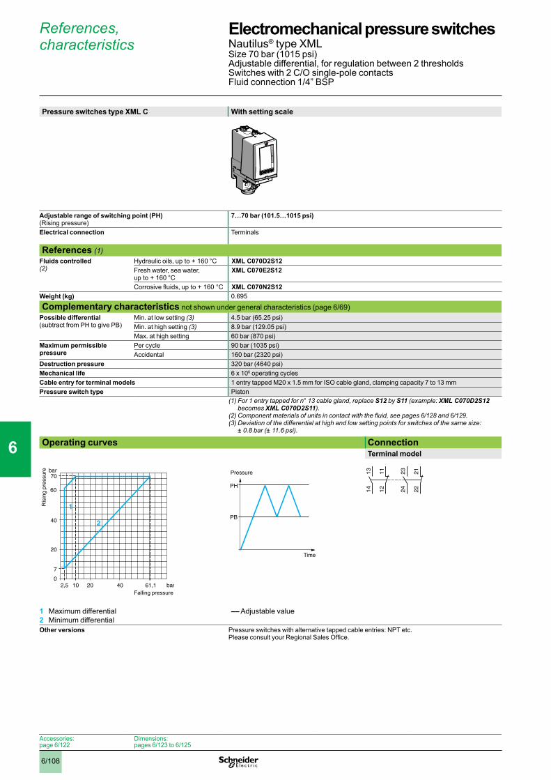
6/108
References, characteristics
Pressure switches type XML C With setting scale
Adjustable range of switching point (PH) (Rising pressure)
7…70 bar (101.5…1015 psi)
Electrical connection Terminals
References (1)Fluids controlled (2)
Hydraulic oils, up to + 160 °C XML C070D2S12Fresh water, sea water, up to + 160 °C
XML C070E2S12
Corrosive fluids, up to + 160 °C XML C070N2S12Weight (kg) 0.695
Complementary characteristics not shown under general characteristics (page 6/69)Possible differential (subtract from PH to give PB)
Min. at low setting (3) 4.5 bar (65.25 psi)Min. at high setting (3) 8.9 bar (129.05 psi)Max. at high setting 60 bar (870 psi)
Maximum permissible pressure
Per cycle 90 bar (1035 psi)Accidental 160 bar (2320 psi)
Destruction pressure 320 bar (4640 psi)Mechanical life 6 x 10⁶ operating cyclesCable entry for terminal models 1 entry tapped M20 x 1.5 mm for ISO cable gland, clamping capacity 7 to 13 mmPressure switch type Piston
(1) For 1 entry tapped for n° 13 cable gland, replace S12 by S11 (example: XML C070D2S12 becomes XML C070D2S11).
(2)Componentmaterialsofunitsincontactwiththefluid,seepages6/128 and 6/129.(3)Deviationofthedifferentialathighandlowsettingpointsforswitchesofthesamesize:
± 0.8 bar (± 11.6 psi). Operating curves Connection
Terminal model
1 Maximum differential2 Minimum differential
–– Adjustable value
Other versions Pressure switches with alternative tapped cable entries: NPT etc. Please consult your Regional Sales Office.
2,5 10 bar
bar
0
7
40
40
20
70
20 61,1
1
2
60
Ris
ing
pres
sure
Falling pressure
PH
PB
Time
Pressure 23
24
22
21
13
14
12
11
Accessories:page 6/122
Dimensions:pages 6/123 to 6/125
Electromechanical pressure switches 0 Nautilus® type XMLSize 70 bar (1015 psi)Adjustable differential, for regulation between 2 thresholdsSwitches with 2 C/O single-pole contactsFluid connection 1/4” BSP
1
2
3
4
5
6
7
8
9
10

6/109
References, characteristics
Pressure switches type XML D Without setting scale
Adjustable range of each switching point (Rising pressure)
2nd stage switching point (PH2) 9.4…70 bar (136.3…1015 psi) 1st stage switching point (PH1) 6.6…67.2 bar (95.7…974.4 psi)
Spread between 2 stages (PH2 - PH1) 2.8…46 bar (40.6…667 psi) Electrical connection Terminals
References (1)Fluids controlled (2)
Hydraulic oils, up to + 160 °C XML D070D1S12Fresh water, sea water, up to + 160 °C
XML D070E1S12
Corrosive fluids, air, up to + 160 °C
XML D070N1S12
Weight (kg) 0.715
Complementary characteristics not shown under general characteristics (page 6/69)Natural differential (subtract from PH1/PH2 to give PB1/PB2)
At low setting (3) 5 bar (72.5 psi)At high setting (4) 9.5 bar (137.75 psi)
Maximum permissible pressure
Per cycle 90 bar (1035 psi)Accidental 160 bar (2320 psi)
Destruction pressure 320 bar (4640 psi)Mechanical life 6 x 10⁶ operating cyclesCable entry for terminal models 1 entry tapped M20 x 1.5 mm for ISO cable gland, clamping capacity 7 to 13 mmPressure switch type Piston
(1) For 1 entry tapped for n° 13 cable gland, replace S12 by S11 (example: XML D070D1S12 becomes XML D070D1S11).
(2)Componentmaterialsofunitsincontactwiththefluid,seepages6/128 and 6/129.(3)Deviationofthedifferentialatlowsettingpointforswitchesofthesamesize:
± 1.5 bar (± 21.75 psi). (4) Deviation of the differential at high setting point for switches of the same size:
± 2 bar (± 29 psi). Operating curvesHigh setting tripping points of contacts 1 and 2 Natural differential of contacts 1 and 2
–– Adjustable value--- Non adjustable valueConnectionTerminal model
Contact 2 (stage 2)
Contact 1 (stage 1)
1 Maximum differential2 Minimum differential
EF Contact 1 (stage 1)GH Contact 2 (stage 2)
Other versions Pressure switches with alternative tapped cable entries: NPT etc. Please consult your Regional Sales Office.
6,6 bar
bar
0
9,4
40
40
20
60
52,6
70
20 24 67,2
1
2
60
PH
2 se
tting
(ris
ing
pres
sure
)
PH1 setting (rising pressure)1,6 bar
bar
0
6,69,4
40
40
4,4
20
60
7067,2
20 60,557,7
G
HF
E
Ris
ing
pres
sure
Falling pressure
PH2
PH1
PB1
PB2
Time
Pressure
23
24
22
21
13
14
12
11
Electromechanical pressure switches 0 Nautilus® type XMLSize 70 bar (1015 psi)Dual stage, fixed differential, for detection at each thresholdSwitches with 2 C/O single-pole contacts (one per stage)Fluid connection 1/4” BSP
1
2
3
4
5
6
7
8
9
10
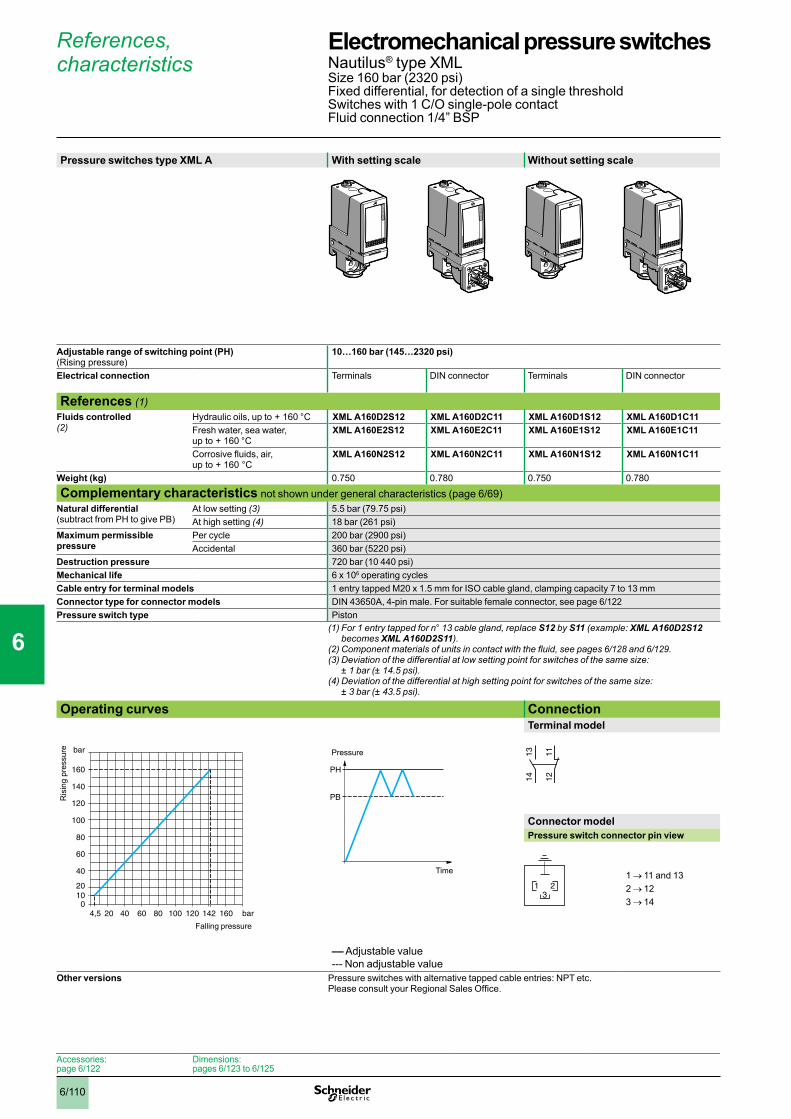
6/110
References, characteristics
Pressure switches type XML A With setting scale Without setting scale
Adjustable range of switching point (PH) (Rising pressure)
10…160 bar (145…2320 psi)
Electrical connection Terminals DIN connector Terminals DIN connector
References (1)Fluids controlled (2)
Hydraulic oils, up to + 160 °C XML A160D2S12 XML A160D2C11 XML A160D1S12 XML A160D1C11Fresh water, sea water, up to + 160 °C
XML A160E2S12 XML A160E2C11 XML A160E1S12 XML A160E1C11
Corrosive fluids, air, up to + 160 °C
XML A160N2S12 XML A160N2C11 XML A160N1S12 XML A160N1C11
Weight (kg) 0.750 0.780 0.750 0.780
Complementary characteristics not shown under general characteristics (page 6/69)Natural differential (subtract from PH to give PB)
At low setting (3) 5.5 bar (79.75 psi)At high setting (4) 18 bar (261 psi)
Maximum permissible pressure
Per cycle 200 bar (2900 psi)Accidental 360 bar (5220 psi)
Destruction pressure 720 bar (10 440 psi)Mechanical life 6 x 10⁶ operating cyclesCable entry for terminal models 1 entry tapped M20 x 1.5 mm for ISO cable gland, clamping capacity 7 to 13 mmConnector type for connector models DIN 43650A, 4-pin male. For suitable female connector, see page 6/122Pressure switch type Piston
(1) For 1 entry tapped for n° 13 cable gland, replace S12 by S11 (example: XML A160D2S12 becomes XML A160D2S11).
(2)Componentmaterialsofunitsincontactwiththefluid,seepages6/128 and 6/129.(3)Deviationofthedifferentialatlowsettingpointforswitchesofthesamesize:
± 1 bar (± 14.5 psi). (4)Deviationofthedifferentialathighsettingpointforswitchesofthesamesize:
± 3 bar (± 43.5 psi). Operating curves Connection
Terminal model
Connector modelPressure switch connector pin view
1 → 11 and 132 → 123 → 14
–– Adjustable value--- Non adjustable value
Other versions Pressure switches with alternative tapped cable entries: NPT etc. Please consult your Regional Sales Office.
bar
bar
040 100 142
40
100
4,5
2010
120 160
60
80
120
140
160
20 60 80
Ris
ing
pres
sure
Falling pressure
PH
PB
Time
Pressure 1314 12
11
321
Accessories:page 6/122
Dimensions:pages 6/123 to 6/125
Electromechanical pressure switches 0 Nautilus® type XMLSize 160 bar (2320 psi)Fixed differential, for detection of a single thresholdSwitches with 1 C/O single-pole contactFluid connection 1/4” BSP
1
2
3
4
5
6
7
8
9
10
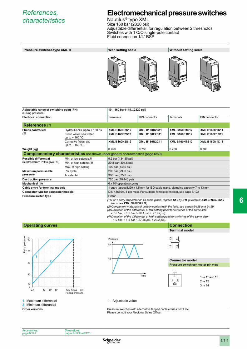
6/111
References, characteristics
Pressure switches type XML B With setting scale Without setting scale
Adjustable range of switching point (PH) (Rising pressure)
10…160 bar (145…2320 psi)
Electrical connection Terminals DIN connector Terminals DIN connector
References (1)Fluids controlled (2)
Hydraulic oils, up to + 160 °C XML B160D2S12 XML B160D2C11 XML B160D1S12 XML B160D1C11Fresh water, sea water, up to + 160 °C
XML B160E2S12 XML B160E2C11 XML B160E1S12 XML B160E1C11
Corrosive fluids, air, up to + 160 °C
XML B160N2S12 XML B160N2C11 XML B160N1S12 XML B160N1C11
Weight (kg) 0.750 0.780 0.750 0.780
Complementary characteristics not shown under general characteristics (page 6/69)Possible differential (subtract from PH to give PB)
Min. at low setting (3) 9.3 bar (134.85 psi)Min. at high setting (4) 20.8 bar (301.6 psi)Max. at high setting 100 bar (1450 psi)
Maximum permissible pressure
Per cycle 200 bar (2900 psi)Accidental 360 bar (5220 psi)
Destruction pressure 720 bar (10 440 psi)Mechanical life 6 x 10⁶ operating cyclesCable entry for terminal models 1 entry tapped M20 x 1.5 mm for ISO cable gland, clamping capacity 7 to 13 mmConnector type for connector models DIN 43650A, 4-pin male. For suitable female connector, see page 6/122Pressure switch type Piston
(1) For 1 entry tapped for n° 13 cable gland, replace S12 by S11 (example: XML B160D2S12 becomes XML B160D2S11).
(2)Componentmaterialsofunitsincontactwiththefluid,seepages6/128 and 6/129.(3)Deviationofthedifferentialatlowsettingpointforswitchesofthesamesize:
- 1.8 bar, + 1.5 bar (- 26.1 psi, + 21.75 psi). (4)Deviationofthedifferentialathighsettingpointforswitchesofthesamesize:
- 1.9 bar, + 1.6 bar (- 27.55 psi, + 23.2 psi). Operating curves Connection
Terminal model
Connector modelPressure switch connector pin view
1 → 11 and 132 → 123 → 14
1 Maximum differential2 Minimum differential
–– Adjustable value
Other versions Pressure switches with alternative tapped cable entries: NPT etc. Please consult your Regional Sales Office.
0,7 bar
bar
040 8060
40
80
120
10
120 139,2
160
12
Ris
ing
pres
sure
Falling pressure
PH
PB
Time
Pressure 1314 12
11
321
Accessories:page 6/122
Dimensions:pages 6/123 to 6/125
Electromechanical pressure switches 0 Nautilus® type XMLSize 160 bar (2320 psi)Adjustable differential, for regulation between 2 thresholdsSwitches with 1 C/O single-pole contactFluid connection 1/4” BSP
1
2
3
4
5
6
7
8
9
10

6/112
References, characteristics
Pressure switches type XML C With setting scale
Adjustable range of switching point (PH) (Rising pressure)
12…160 bar (174…2320 psi)
Electrical connection Terminals
References (1)Fluids controlled (2)
Hydraulic oils, up to + 160 °C XML C160D2S12Fresh water, sea water, up to + 160 °C
XML C160E2S12
Corrosive fluids, up to + 160 °C XML C160N2S12Weight (kg) 0.750
Complementary characteristics not shown under general characteristics (page 6/69)Possible differential (subtract from PH to give PB)
Min. at low setting (3) 9 bar (130.5 psi)Min. at high setting (3) 21 bar (304.5 psi)Max. at high setting 110 bar (1590 psi)
Maximum permissible pressure
Per cycle 200 bar (2900 psi)Accidental 360 bar (5220 psi)
Destruction pressure 720 bar (10 440 psi)Mechanical life 6 x 10⁶ operating cyclesCable entry for terminal models 1 entry tapped M20 x 1.5 mm for ISO cable gland, clamping capacity 7 to 13 mmPressure switch type Piston
(1) For 1 entry tapped for n° 13 cable gland, replace S12 by S11 (example: XML C160D2S12 becomes XML C160D2S11).
(2)Componentmaterialsofunitsincontactwiththefluid,seepages6/128 and 6/129.(3)Deviationofthedifferentialathighandlowsettingpointsforswitchesofthesamesize:
± 0.9 bar (± 13.05 psi). Operating curves Connection
Terminal model
1 Maximum differential2 Minimum differential
–– Adjustable value
Other versions Pressure switches with alternative tapped cable entries: NPT etc. Please consult your Regional Sales Office.
3 bar
bar
050
50
12
100 139
160
1
2100
Ris
ing
pres
sure
Falling pressure
PH
PB
Time
Pressure 23
24
22
21
13
14
12
11
Accessories:page 6/122
Dimensions:pages 6/123 to 6/125
Electromechanical pressure switches 0 Nautilus® type XMLSize 160 bar (2320 psi)Adjustable differential, for regulation between 2 thresholdsSwitches with 2 C/O single-pole contactsFluid connection 1/4” BSP
1
2
3
4
5
6
7
8
9
10

6/113
References, characteristics
Pressure switches type XML D Without setting scale
Adjustable range of each switching point (Rising pressure)
2nd stage switching point (PH2) 16.5…160 bar (239.25…2320 psi) 1st stage switching point (PH1) 10.5…154 bar (152.25…2233 psi)
Spread between 2 stages (PH2 - PH1) 6…83 bar (87…1203.5 psi) Electrical connection Terminals
References (1)Fluids controlled (2)
Hydraulic oils, up to + 160 °C XML D160D1S12Fresh water, sea water, up to + 160 °C
XML D160E1S12
Corrosive fluids, air, up to + 160 °C
XML D160N1S12
Weight (kg) 0.750
Complementary characteristics not shown under general characteristics (page 6/69)Natural differential (subtract from PH1/PH2 to give PB1/PB2)
At low setting (3) 8.8 bar (127.6 psi)At high setting (4) 20 bar (290 psi)
Maximum permissible pressure
Per cycle 200 bar (2900 psi)Accidental 360 bar (5220 psi)
Destruction pressure 720 bar (10 440 psi)Mechanical life 6 x 10⁶ operating cyclesCable entry for terminal models 1 entry tapped M20 x 1.5 mm for ISO cable gland, clamping capacity 7 to 13 mmPressure switch type Piston
(1) For 1 entry tapped for n° 13 cable gland, replace S12 by S11 (example: XML D160D1S12 becomes XML D160D1S11).
(2)Componentmaterialsofunitsincontactwiththefluid,seepages6/128 and 6/129.(3)Deviationofthedifferentialatlowsettingpointforswitchesofthesamesize:
± 1.5 bar (± 21.75 psi). (4)Deviationofthedifferentialathighsettingpointforswitchesofthesamesize:
± 7 bar (± 101.5 psi). Operating curvesHigh setting tripping points of contacts 1 and 2 Natural differential of contacts 1 and 2
–– Adjustable value--- Non adjustable valueConnectionTerminal model
Contact 2 (stage 2)
Contact 1 (stage 1)
1 Maximum differential2 Minimum differential
EF Contact 1 (stage 1)GH Contact 2 (stage 2)
Other versions Pressure switches with alternative tapped cable entries: NPT etc. Please consult your Regional Sales Office.
0 10,5 bar
bar
040 7760
40
80
94,5
120
1016,5
120100 154
160
1
2
PH
2 se
tting
(ris
ing
pres
sure
)
PH1 setting (rising pressure)
bar
bar
040 100 134140
40
100
1,77,7
10,516,5
160
60
80
120
140
154
60 80
E
F
H
G
Ris
ing
pres
sure
Falling pressure
PH2
PH1
PB1
PB2
Time
Pressure
23
24
22
21
13
14
12
11
Accessories:page 6/122
Dimensions:pages 6/123 to 6/125
Electromechanical pressure switches 0 Nautilus® type XMLSize 160 bar (2320 psi)Dual stage, fixed differential, for detection at each thresholdSwitches with 2 C/O single-pole contacts (one per stage)Fluid connection 1/4” BSP
1
2
3
4
5
6
7
8
9
10

6/114
References, characteristics
Pressure switches type XML A With setting scale Without setting scale
Adjustable range of switching point (PH) (Rising pressure)
20…300 bar (290…4350 psi)
Electrical connection Terminals DIN connector Terminals DIN connector
References (1)Fluids controlled (2) (5)
Hydraulic oils, up to + 160 °C XML A300D2S12 XML A300D2C11 XML A300D1S12 XML A300D1C11Fresh water, sea water, up to + 160 °C
XML A300E2S12 XML A300E2C11 XML A300E1S12 XML A300E1C11
Corrosive fluids, air, up to + 160 °C
XML A300N2S12 XML A300N2C11 XML A300N1S12 XML A300N1C11
Weight (kg) 0.750 0.780 0.750 0.780
Complementary characteristics not shown under general characteristics (page 6/69)Natural differential (subtract from PH to give PB)
At low setting (3) 16.5 bar (239.25 psi)At high setting (4) 35 bar (507.5 psi)
Maximum permissible pressure
Per cycle 375 bar (5437.5 psi)Accidental 675 bar (9787.5 psi)
Destruction pressure 1350 bar (19 575 psi)Mechanical life 3 x 10⁶ operating cyclesCable entry for terminal models 1 entry tapped M20 x 1.5 mm for ISO cable gland, clamping capacity 7 to 13 mmConnector type for connector models DIN 43650A, 4-pin male. For suitable female connector, see page 6/122Pressure switch type Piston
(1) For 1 entry tapped for n° 13 cable gland, replace S12 by S11 (example: XML A300D2S12 becomes XML A300D2S11).
(2)Componentmaterialsofunitsincontactwiththefluid,seepages6/128 and 6/129.(3)Deviationofthedifferentialatlowsettingpointforswitchesofthesamesize:
± 3 bar (± 43.5 psi). (4) Deviationofthedifferentialathighsettingpointforswitchesofthesamesize:
± 6 bar (± 87 psi). (5)Onlyforcontrolofgroup2fluids,inaccordancewithdirective97/23/EEC.
Operating curves ConnectionTerminal model
Connector modelPressure switch connector pin view
1 → 11 and 132 → 123 → 14
–– Adjustable value--- Non adjustable value
Other versions Pressure switches with alternative tapped cable entries: NPT etc. Please consult your Regional Sales Office.
3,5 bar
bar
0100 200 265 300
100
200
300
20
Ris
ing
pres
sure
Falling pressure
PH
PB
Time
Pressure 1314 12
11
321
Accessories:page 6/122
Dimensions:pages 6/123 to 6/125
Electromechanical pressure switches 0 Nautilus® type XMLSize 300 bar (4350 psi)Fixed differential, for detection of a single thresholdSwitches with 1 C/O single-pole contactFluid connection 1/4” BSP
1
2
3
4
5
6
7
8
9
10

6/115
References, characteristics
Pressure switches type XML B With setting scale Without setting scale
Adjustable range of switching point (PH) (Rising pressure)
22…300 bar (319…4350 psi)
Electrical connection Terminals DIN connector Terminals DIN connector
References (1)Fluids controlled (2) (5)
Hydraulic oils, up to + 160 °C XML B300D2S12 XML B300D2C11 XML B300D1S12 XML B300D1C11Fresh water, sea water, up to + 160 °C
XML B300E2S12 XML B300E2C11 XML B300E1S12 XML B300E1C11
Corrosive fluids, air, up to + 160 °C
XML B300N2S12 XML B300N2C11 XML B300N1S12 XML B300N1C11
Weight (kg) 0.750 0.780 0.750 0.780
Complementary characteristics not shown under general characteristics (page 6/69)Possible differential (subtract from PH to give PB)
Min. at low setting (3) 19.4 bar (281.3 psi)Min. at high setting (4) 37 bar (536.5 psi)Max. at high setting 200 bar (2900 psi)
Maximum permissible pressure
Per cycle 375 bar (5437.5 psi)Accidental 675 bar (9787.5 psi)
Destruction pressure 1350 bar (19 575 psi)Mechanical life 3 x 10⁶ operating cyclesCable entry for terminal models 1 entry tapped M20 x 1.5 mm for ISO cable gland, clamping capacity 7 to 13 mmConnector type for connector models DIN 43650A, 4-pin male. For suitable female connector, see page 6/122Pressure switch type Piston
(1) For 1 entry tapped for n° 13 cable gland, replace S12 by S11 (example: XML B300D2S12 becomes XML B300D2S11).
(2)Componentmaterialsofunitsincontactwiththefluid,seepages6/128 and 6/129.(3)Deviationofthedifferentialatlowsettingpointforswitchesofthesamesize:
- 1.5 bar, + 1.7 bar (- 21.75 psi, + 24.65 psi). (4)Deviationofthedifferentialathighsettingpointforswitchesofthesamesize:
- 1 bar, + 4 bar (- 14.5 psi, + 58 psi).(5)Onlyforcontrolofgroup2fluids,inaccordancewithdirective97/23/EEC.
Operating curves ConnectionTerminal model
Connector modelPressure switch connector pin view
1 → 11 and 132 → 123 → 14
1 Maximum differential2 Minimum differential
–– Adjustable value
Other versions Pressure switches with alternative tapped cable entries: NPT etc. Please consult your Regional Sales Office.
bar
bar
0
200
100
22
300
2632001002,6
2
1
Ris
ing
pres
sure
Falling pressure
PH
PB
Time
Pressure 1314 12
11
321
Accessories:page 6/122
Dimensions:pages 6/123 to 6/125
Electromechanical pressure switches 0 Nautilus® type XMLSize 300 bar (4350 psi)Adjustable differential, for regulation between 2 thresholdsSwitches with 1 C/O single-pole contactFluid connection 1/4” BSP
1
2
3
4
5
6
7
8
9
10
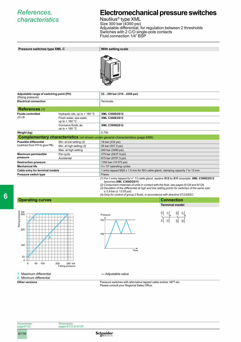
6/116
References, characteristics
Pressure switches type XML C With setting scale
Adjustable range of switching point (PH) (Rising pressure)
22…300 bar (319…4350 psi)
Electrical connection Terminals
References (1)Fluids controlled (2) (4)
Hydraulic oils, up to + 160 °C XML C300D2S12Fresh water, sea water, up to + 160 °C
XML C300E2S12
Corrosive fluids, air, up to + 160 °C
XML C300N2S12
Weight (kg) 0.750
Complementary characteristics not shown under general characteristics (page 6/69)Possible differential (subtract from PH to give PB)
Min. at low setting (3) 16 bar (232 psi)Min. at high setting (3) 35 bar (507.5 psi)Max. at high setting 240 bar (3480 psi)
Maximum permissible pressure
Per cycle 375 bar (5437.5 psi)Accidental 675 bar (9787.5 psi)
Destruction pressure 1350 bar (19 575 psi)Mechanical life 3 x 10⁶ operating cyclesCable entry for terminal models 1 entry tapped M20 x 1.5 mm for ISO cable gland, clamping capacity 7 to 13 mmPressure switch type Piston
(1) For 1 entry tapped for n° 13 cable gland, replace S12 by S11 (example: XML C300D2S12 becomes XML C300D2S11).
(2)Componentmaterialsofunitsincontactwiththefluid,seepages6/128 and 6/129.(3)Deviationofthedifferentialathighandlowsettingpointsforswitchesofthesamesize:
± 0.9 bar (± 13.05 psi). (4)Onlyforcontrolofgroup2fluids,inaccordancewithdirective97/23/EEC.
Operating curves ConnectionTerminal model
1 Maximum differential2 Minimum differential
–– Adjustable value
Other versions Pressure switches with alternative tapped cable entries: NPT etc. Please consult your Regional Sales Office.
bar
bar
0
200
100
22
300
265200606
2
1
100
Ris
ing
pres
sure
Falling pressure
PH
PB
Time
Pressure 23
24
22
21
13
14
12
11
Accessories:page 6/122
Dimensions:pages 6/123 to 6/125
Electromechanical pressure switches 0 Nautilus® type XMLSize 300 bar (4350 psi)Adjustable differential, for regulation between 2 thresholdsSwitches with 2 C/O single-pole contactsFluid connection 1/4” BSP
1
2
3
4
5
6
7
8
9
10

6/117
References, characteristics
Pressure switches type XML D Without setting scale
Adjustable range of each switching point (Rising pressure)
2nd stage switching point (PH2) 36…300 bar (522…4350 psi) 1st stage switching point (PH1) 25…289 bar (362.5…4190.5 psi)
Spread between 2 stages (PH2 - PH1) 11…189 bar (159.5…2740.5 psi) Electrical connection Terminals
References (1)Fluids controlled (2) (5)
Hydraulic oils, up to + 160 °C XML D300D1S12Fresh water, sea water, up to + 160 °C
XML D300E1S12
Corrosive fluids, air, up to + 160 °C
XML D300N1S12
Weight (kg) 0.750
Complementary characteristics not shown under general characteristics (page 6/69)Natural differential (subtract from PH1/PH2 to give PB1/PB2)
At low setting (3) 17 bar (246.5 psi)At high setting (4) 42 bar (609 psi)
Maximum permissible pressure
Per cycle 375 bar (5437.5 psi)Accidental 675 bar (9787.5 psi)
Destruction pressure 1350 bar (19 575 psi)Mechanical life 3 x 10⁶ operating cyclesCable entry for terminal models 1 entry tapped M20 x 1.5 mm for ISO cable gland, clamping capacity 7 to 13 mmPressure switch type Piston
(1) For 1 entry tapped for n° 13 cable gland, replace S12 by S11 (example: XML D300D1S12 becomes XML D300D1S11).
(2)Componentmaterialsofunitsincontactwiththefluid,seepages6/128 and 6/129.(3)Deviationofthedifferentialatlowsettingpointforswitchesofthesamesize:
± 2.5 bar (± 36.25 psi). (4)Deviationofthedifferentialathighsettingpointforswitchesofthesamesize:
± 9 bar (± 130.5 psi).(5)Onlyforcontrolofgroup2fluids,inaccordancewithdirective97/23/EEC.
Operating curvesHigh setting tripping points of contacts 1 and 2 Natural differential of contacts 1 and 2
–– Adjustable value--- Non adjustable valueConnectionTerminal model
Contact 2 (stage 2)
Contact 1 (stage 1)
1 Maximum differential2 Minimum differential
EF Contact 1 (stage 1)GH Contact 2 (stage 2)
Other versions Pressure switches with alternative tapped cable entries: NPT etc. Please consult your Regional Sales Office.
bar
bar
0
200215
100
2036
300
2892001110 25
2
1
PH
2 se
tting
(ris
ing
pres
sure
)
PH1 setting (rising pressure)8 19 bar
bar
0100 200 247 258
100
200
300289
2536
E
G
H
F
300
Ris
ing
pres
sure
Falling pressure
PH2
PH1
PB1
PB2
Time
Pressure
23
24
22
21
13
14
12
11
Accessories:page 6/122
Dimensions:pages 6/123 to 6/125
Electromechanical pressure switches 0 Nautilus® type XMLSize 300 bar (4350 psi)Dual stage, fixed differential, for detection at each thresholdSwitches with 2 C/O single-pole contacts (one per stage)Fluid connection 1/4” BSP
1
2
3
4
5
6
7
8
9
10
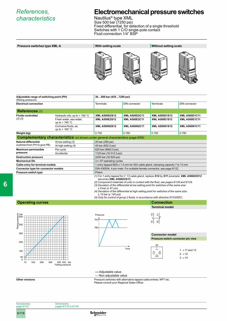
6/118
References, characteristics
Pressure switches type XML A With setting scale Without setting scale
Adjustable range of switching point (PH) (Rising pressure)
30…500 bar (435…7250 psi)
Electrical connection Terminals DIN connector Terminals DIN connector
References (1)Fluids controlled (2) (5)
Hydraulic oils, up to + 160 °C XML A500D2S12 XML A500D2C11 XML A500D1S12 XML A500D1C11Fresh water, sea water, up to + 160 °C
XML A500E2S12 XML A500E2C11 XML A500E1S12 XML A500E1C11
Corrosive fluids, air, up to + 160 °C
XML A500N2S12 XML A500N2C11 XML A500N1S12 XML A500N1C11
Weight (kg) 0.750 0.780 0.750 0.780
Complementary characteristics not shown under general characteristics (page 6/69)Natural differential (subtract from PH to give PB)
At low setting (3) 20 bar (290 psi)At high setting (4) 45 bar (652.5 psi)
Maximum permissible pressure
Per cycle 625 bar (9062.5 psi)Accidental 1125 bar (16 312.5 psi)
Destruction pressure 2250 bar (32 625 psi)Mechanical life 3 x 10⁶ operating cyclesCable entry for terminal models 1 entry tapped M20 x 1.5 mm for ISO cable gland, clamping capacity 7 to 13 mmConnector type for connector models DIN 43650A, 4-pin male. For suitable female connector, see page 6/122Pressure switch type Piston
(1) For 1 entry tapped for n° 13 cable gland, replace S12 by S11 (example: XML A500D2S12 becomes XML A500D2S11).
(2)Componentmaterialsofunitsincontactwiththefluid,seepages6/128 and 6/129.(3)Deviationofthedifferentialatlowsettingpointforswitchesofthesamesize:
± 6 bar (± 87 psi). (4)Deviationofthedifferentialathighsettingpointforswitchesofthesamesize:
± 10 bar (± 145 psi). (5)Onlyforcontrolofgroup2fluids,inaccordancewithdirective97/23/EEC.
Operating curves ConnectionTerminal model
Connector modelPressure switch connector pin view
1 → 11 and 132 → 123 → 14
–– Adjustable value--- Non adjustable value
Other versions Pressure switches with alternative tapped cable entries: NPT etc. Please consult your Regional Sales Office.
bar
bar
0100 200 400
100
200
300
10
30
300
400
500
455
Ris
ing
pres
sure
Falling pressure
PH
PB
Time
Pressure 1314 12
11
321
Accessories:page 6/122
Dimensions:pages 6/123 to 6/125
Electromechanical pressure switches 0 Nautilus® type XMLSize 500 bar (7250 psi)Fixed differential, for detection of a single thresholdSwitches with 1 C/O single-pole contactFluid connection 1/4” BSP
1
2
3
4
5
6
7
8
9
10
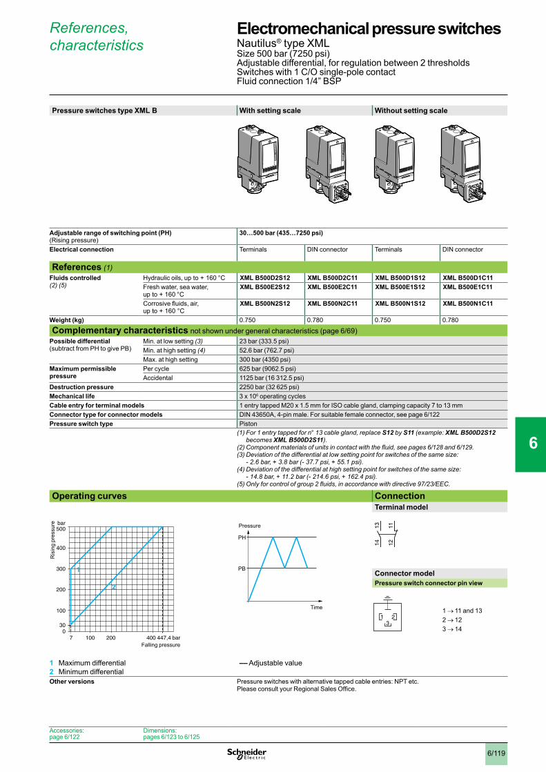
6/119
References, characteristics
Pressure switches type XML B With setting scale Without setting scale
Adjustable range of switching point (PH) (Rising pressure)
30…500 bar (435…7250 psi)
Electrical connection Terminals DIN connector Terminals DIN connector
References (1)Fluids controlled (2) (5)
Hydraulic oils, up to + 160 °C XML B500D2S12 XML B500D2C11 XML B500D1S12 XML B500D1C11Fresh water, sea water, up to + 160 °C
XML B500E2S12 XML B500E2C11 XML B500E1S12 XML B500E1C11
Corrosive fluids, air, up to + 160 °C
XML B500N2S12 XML B500N2C11 XML B500N1S12 XML B500N1C11
Weight (kg) 0.750 0.780 0.750 0.780
Complementary characteristics not shown under general characteristics (page 6/69)Possible differential (subtract from PH to give PB)
Min. at low setting (3) 23 bar (333.5 psi)Min. at high setting (4) 52.6 bar (762.7 psi)Max. at high setting 300 bar (4350 psi)
Maximum permissible pressure
Per cycle 625 bar (9062.5 psi)Accidental 1125 bar (16 312.5 psi)
Destruction pressure 2250 bar (32 625 psi)Mechanical life 3 x 10⁶ operating cyclesCable entry for terminal models 1 entry tapped M20 x 1.5 mm for ISO cable gland, clamping capacity 7 to 13 mmConnector type for connector models DIN 43650A, 4-pin male. For suitable female connector, see page 6/122Pressure switch type Piston
(1) For 1 entry tapped for n° 13 cable gland, replace S12 by S11 (example: XML B500D2S12 becomes XML B500D2S11).
(2)Componentmaterialsofunitsincontactwiththefluid,seepages6/128 and 6/129.(3)Deviationofthedifferentialatlowsettingpointforswitchesofthesamesize:
- 2.6 bar, + 3.8 bar (- 37.7 psi, + 55.1 psi). (4)Deviationofthedifferentialathighsettingpointforswitchesofthesamesize:
- 14.8 bar, + 11.2 bar (- 214.6 psi, + 162.4 psi).(5)Onlyforcontrolofgroup2fluids,inaccordancewithdirective97/23/EEC.
Operating curves ConnectionTerminal model
Connector modelPressure switch connector pin view
1 → 11 and 132 → 123 → 14
1 Maximum differential2 Minimum differential
–– Adjustable value
Other versions Pressure switches with alternative tapped cable entries: NPT etc. Please consult your Regional Sales Office.
bar
bar
0100 200 447,4400
100
200
300
7
30
400
500
2
1
Ris
ing
pres
sure
Falling pressure
PH
PB
Time
Pressure 1314 12
11
321
Accessories:page 6/122
Dimensions:pages 6/123 to 6/125
Electromechanical pressure switches 0 Nautilus® type XMLSize 500 bar (7250 psi)Adjustable differential, for regulation between 2 thresholdsSwitches with 1 C/O single-pole contactFluid connection 1/4” BSP
1
2
3
4
5
6
7
8
9
10

6/120
References, characteristics
Pressure switches type XML C With setting scale
Adjustable range of switching point (PH) (Rising pressure)
30…500 bar (435…7250 psi)
Electrical connection Terminals
References (1)Fluids controlled (2) (4)
Hydraulic oils, up to + 160 °C XML C500D2S12Fresh water, sea water, up to + 160 °C
XML C500E2S12
Corrosive fluids, air, up to + 160 °C
XML C500N2S12
Weight (kg) 0.750
Complementary characteristics not shown under general characteristics (page 6/69)Possible differential (subtract from PH to give PB)
Min. at low setting (3) 19 bar (275.5 psi)Min. at high setting (3) 52 bar (754 psi)Max. at high setting 340 bar (4930 psi)
Maximum permissible pressure
Per cycle 625 bar (9062.5 psi)Accidental 1125 bar (16 312.5 psi)
Destruction pressure 2250 bar (32 625 psi)Mechanical life 3 x 10⁶ operating cyclesCable entry for terminal models 1 entry tapped M20 x 1.5 mm for ISO cable gland, clamping capacity 7 to 13 mmPressure switch type Piston
(1) For 1 entry tapped for n° 13 cable gland, replace S12 by S11 (example: XML C500D2S12 becomes XML C500D2S11).
(2)Componentmaterialsofunitsincontactwiththefluid,seepages6/128 and 6/129.(3)Deviationofthedifferentialathighandlowsettingpointsforswitchesofthesamesize:
± 0.9 bar (± 13.05 psi). (4)Onlyforcontrolofgroup2fluids,inaccordancewithdirective97/23/EEC.
Operating curves ConnectionTerminal model
1 Maximum differential2 Minimum differential
–– Adjustable value
Other versions Pressure switches with alternative tapped cable entries: NPT etc. Please consult your Regional Sales Office.
bar
bar
0100 160 300 448400
100
200
300
11
30
400
500
2
1
200
Ris
ing
pres
sure
Falling pressure
PH
PB
Time
Pressure 23
24
22
21
13
14
12
11
Accessories:page 6/122
Dimensions:pages 6/123 to 6/125
Electromechanical pressure switches 0 Nautilus® type XMLSize 500 bar (7250 psi)Adjustable differential, for regulation between 2 thresholdsSwitches with 2 C/O single-pole contactsFluid connection 1/4” BSP
1
2
3
4
5
6
7
8
9
10

6/121
References, characteristics
Pressure switches type XML D Without setting scale
Adjustable range of each switching point (Rising pressure)
2nd stage switching point (PH2) 41…500 bar (594.5…7250 psi) 1st stage switching point (PH1) 25…484 bar (362.5…7018 psi)
Spread between 2 stages (PH2 - PH1) 16…244 bar (232…3538 psi) Electrical connection Terminals
References (1)Fluids controlled (2) (5)
Hydraulic oils, up to + 160 °C XML D500D1S12Fresh water, sea water, up to + 160 °C
XML D500E1S12
Corrosive fluids, air, up to + 160 °C
XML D500N1S12
Weight (kg) 0.750
Complementary characteristics not shown under general characteristics (page 6/69)Natural differential (subtract from PH1/PH2 to give PB1/PB2)
At low setting (3) 21 bar (304.5 psi)At high setting (4) 65 bar (942.5 psi)
Maximum permissible pressure
Per cycle 625 bar (9062.5 psi)Accidental 1125 bar (16 312.5 psi)
Destruction pressure 2250 bar (32 625 psi)Mechanical life 3 x 10⁶ operating cyclesCable entry for terminal models 1 entry tapped M20 x 1.5 mm for ISO cable gland, clamping capacity 7 to 13 mmPressure switch type Piston
(1) For 1 entry tapped for n° 13 cable gland, replace S12 by S11 (example: XML D500D1S12 becomes XML D500D1S11).
(2)Componentmaterialsofunitsincontactwiththefluid,seepages6/128 and 6/129.(3)Deviationofthedifferentialatlowsettingpointforswitchesofthesamesize:
± 3 bar (± 43.5 psi). (4)Deviationofthedifferentialathighsettingpointforswitchesofthesamesize:
± 10 bar (± 145 psi).(5)Onlyforcontrolofgroup2fluids,inaccordancewithdirective97/23/EEC.
Operating curvesHigh setting tripping points of contacts 1 and 2 Natural differential of contacts 1 and 2
–– Adjustable value--- Non adjustable valueConnectionTerminal model
Contact 2 (stage 2)
Contact 1 (stage 1)
1 Maximum differential2 Minimum differential
EF Contact 1 (stage 1)GH Contact 2 (stage 2)
Other versions Pressure switches with alternative tapped cable entries: NPT etc. Please consult your Regional Sales Office.
bar
bar
0100 200 256300 484400
100
200
273,5300
25
41
400
500
2
1
PH
2 se
tting
(ris
ing
pres
sure
)
PH1 setting (rising pressure)bar
bar
0100 200 419
100
200
300
4 20
2541
300
400
484
435
GE
FH
Ris
ing
pres
sure
Falling pressure
PH2
PH1
PB1
PB2
Time
Pressure
23
24
22
21
13
14
12
11
Accessories:page 6/122
Dimensions:pages 6/123 to 6/125
Electromechanical pressure switches 0 Nautilus® type XMLSize 500 bar (7250 psi)Dual stage, fixed differential, for detection at each thresholdSwitches with 2 C/O single-pole contacts (one per stage)Fluid connection 1/4” BSP
1
2
3
4
5
6
7
8
9
10
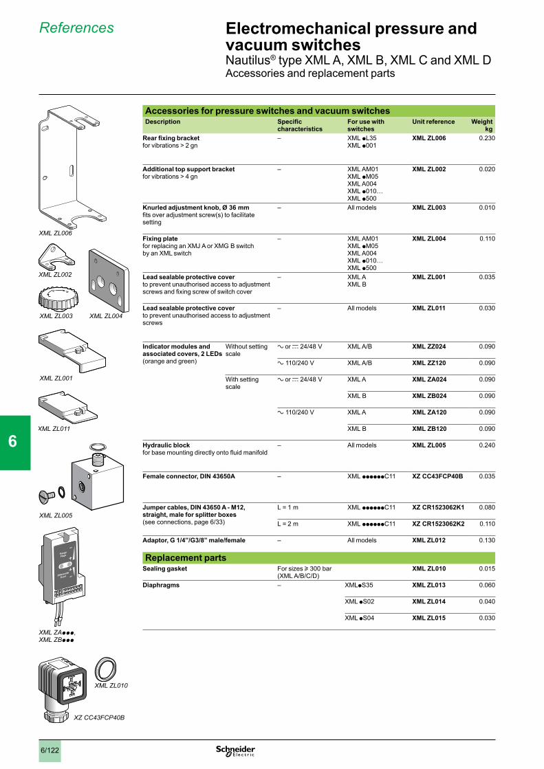
6/122
References
Accessories for pressure switches and vacuum switchesDescription Specific
characteristicsFor use with switches
Unit reference Weightkg
Rear fixing bracket for vibrations > 2 gn
– XML pL35XML p001
XML ZL006 0.230
Additional top support bracket for vibrations > 4 gn
– XML AM01XML pM05XML A004XML p010… XML p500
XML ZL002 0.020
Knurled adjustment knob, Ø 36 mm fits over adjustment screw(s) to facilitate setting
– All models XML ZL003 0.010
Fixing plate for replacing an XMJ A or XMG B switch by an XML switch
– XML AM01XML pM05XML A004XML p010… XML p500
XML ZL004 0.110
Lead sealable protective cover to prevent unauthorised access to adjustment screws and fixing screw of switch cover
– XML AXML B
XML ZL001 0.035
Lead sealable protective cover to prevent unauthorised access to adjustment screws
– All models XML ZL011 0.030
Indicator modules and associated covers, 2 LEDs (orange and green)
Without setting scale
a or c 24/48 V XML A/B XML ZZ024 0.090
a 110/240 V XML A/B XML ZZ120 0.090
With setting scale
a or c 24/48 V XML A XML ZA024 0.090
XML B XML ZB024 0.090
a 110/240 V XML A XML ZA120 0.090
XML B XML ZB120 0.090
Hydraulic block for base mounting directly onto fluid manifold
– All models XML ZL005 0.240
Female connector, DIN 43650A – XML ppppppC11 XZ CC43FCP40B 0.035
Jumper cables, DIN 43650 A - M12, straight, male for splitter boxes (see connections, page 6/33)
L = 1 m XML ppppppC11 XZ CR1523062K1 0.080
L = 2 m XML ppppppC11 XZ CR1523062K2 0.110
Adaptor, G 1/4”/G3/8” male/female – All models XML ZL012 0.130
Replacement partsSealing gasket For sizes u 300 bar
(XML A/B/C/D)XML ZL010 0.015
Diaphragms – XMLpS35 XML ZL013 0.060
XML pS02 XML ZL014 0.040
XML pS04 XML ZL015 0.030
XML ZL006
XML ZL003 XML ZL004
XML ZL001
XML ZL002
XML ZL005
XML ZAppp, XML ZBppp
XZ CC43FCP40B
XML ZL010
XML ZL011
Electromechanical pressure and vacuum switches 0 Nautilus® type XML A, XML B, XML C and XML D Accessories and replacement parts
1
2
3
4
5
6
7
8
9
10
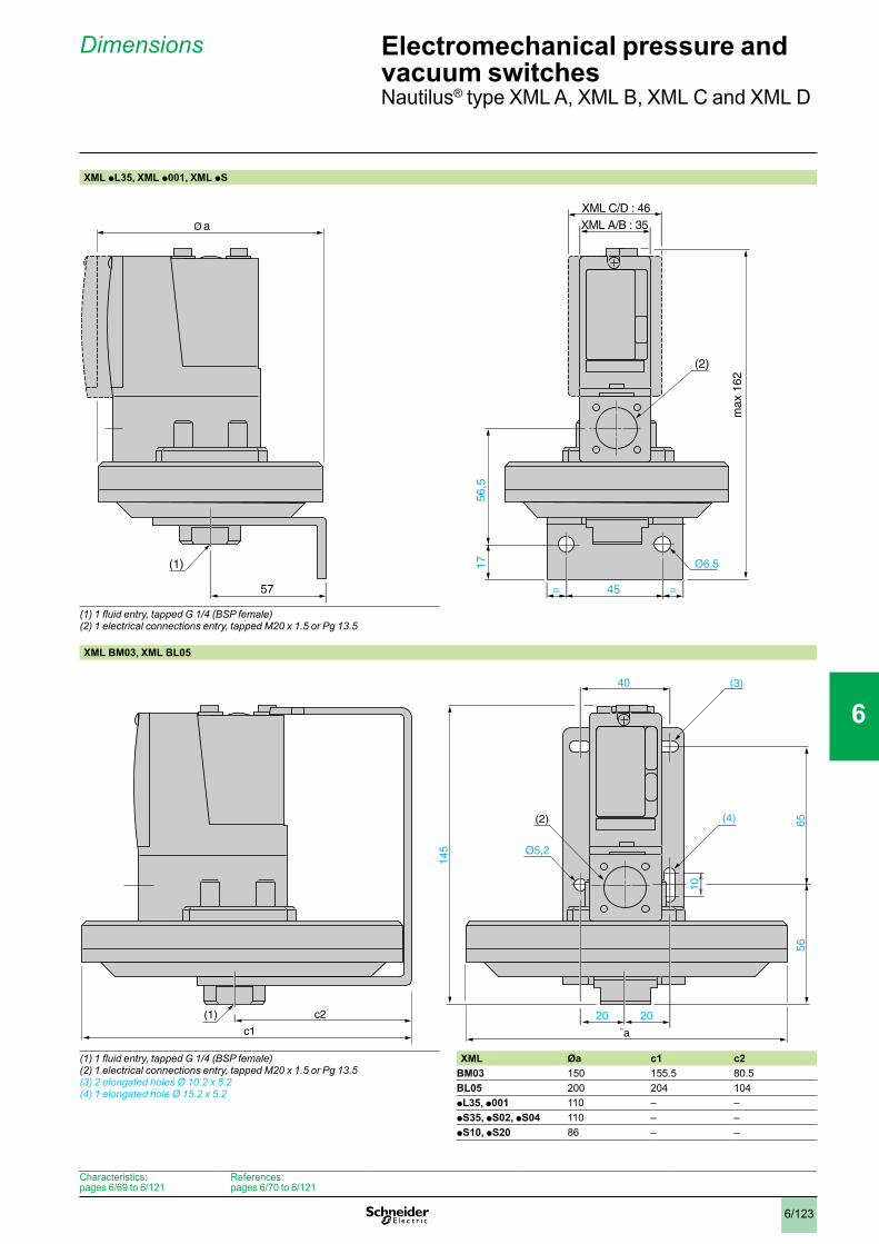
6/123
Dimensions
XML pL35, XML p001, XML pS
(1)1fluidentry,tappedG1/4(BSPfemale)(2) 1 electrical connections entry, tapped M20 x 1.5 or Pg 13.5
XML BM03, XML BL05
(1)1fluidentry,tappedG1/4(BSPfemale)(2) 1 electrical connections entry, tapped M20 x 1.5 or Pg 13.5(3) 2 elongated holes Ø 10.2 x 5.2(4) 1 elongated hole Ø 15.2 x 5.2
XML Øa c1 c2BM03 150 155.5 80.5BL05 200 204 104pL35, p001 110 – –pS35, pS02, pS04 110 – –pS10, pS20 86 – –
56,5
17
45 ==57
(1)
(2)
XML C/D : 46XML A/B : 35
max
162
a
c1
40
20 20
145
56
65
10(3)
(4)
c2(1)
(2)
¯a
Characteristics: pages 6/69 to 6/121
References: pages 6/70 to 6/121
Electromechanical pressure and vacuum switches 0 Nautilus® type XML A, XML B, XML C and XML D
1
2
3
4
5
6
7
8
9
10
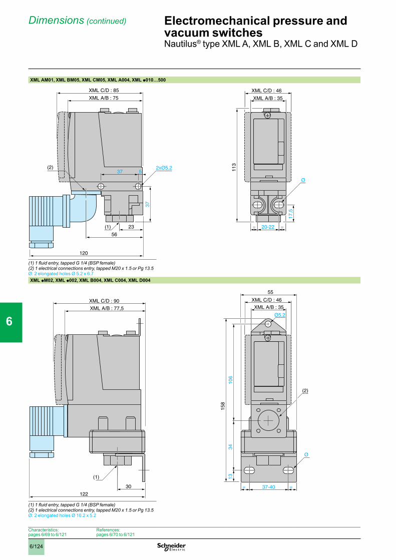
6/124
Dimensions(continued)
XML AM01, XML BM05, XML CM05, XML A004, XML p010…500
(1)1fluidentry,tappedG1/4(BSPfemale)(2) 1 electrical connections entry, tapped M20 x 1.5 or Pg 13.5Ø: 2 elongated holes Ø 5.2 x 6.7XML pM02, XML p002, XML B004, XML C004, XML D004
(1)1fluidentry,tappedG1/4(BSPfemale)(2) 1 electrical connections entry, tapped M20 x 1.5 or Pg 13.5Ø: 2 elongated holes Ø 10.2 x 5.2
37
(2)
XML A/B : 75
23(1)
37 5
56
120
XML C/D : 46
XML A/B : 35
20-22= =11
3
17,5
XML C/D : 85
XML A/B : 77,5
XML C/D : 46
XML A/B : 35XML C/D : 90
1334
55
37-40= =30
158
Ø
(2)
(1)
122
Ø5,2
106
Characteristics: pages 6/69 to 6/121
References: pages 6/70 to 6/121
Electromechanical pressure and vacuum switches 0 Nautilus® type XML A, XML B, XML C and XML D
1
2
3
4
5
6
7
8
9
10
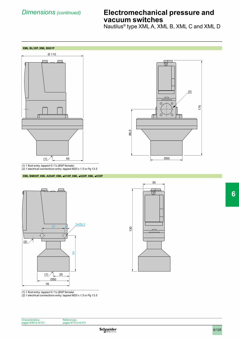
6/125
Dimensions(continued)
XML BL35P, XML B001P
(1)1fluidentry,tappedG1¼(BSPfemale)(2) 1 electrical connections entry, tapped M20 x 1.5 or Pg 13.5
XML BM05P, XML A004P, XML p010P, XML p020P, XML p035P
(1)1fluidentry,tappedG1¼(BSPfemale)(2) 1 electrical connections entry, tapped M20 x 1.5 or Pg 13.5
86,5
175
55(1)
(2)
130
54
(2)
76
35
25(1)
37 5
Characteristics: pages 6/69 to 6/121
References: pages 6/70 to 6/121
Electromechanical pressure and vacuum switches 0 Nautilus® type XML A, XML B, XML C and XML D
1
2
3
4
5
6
7
8
9
10
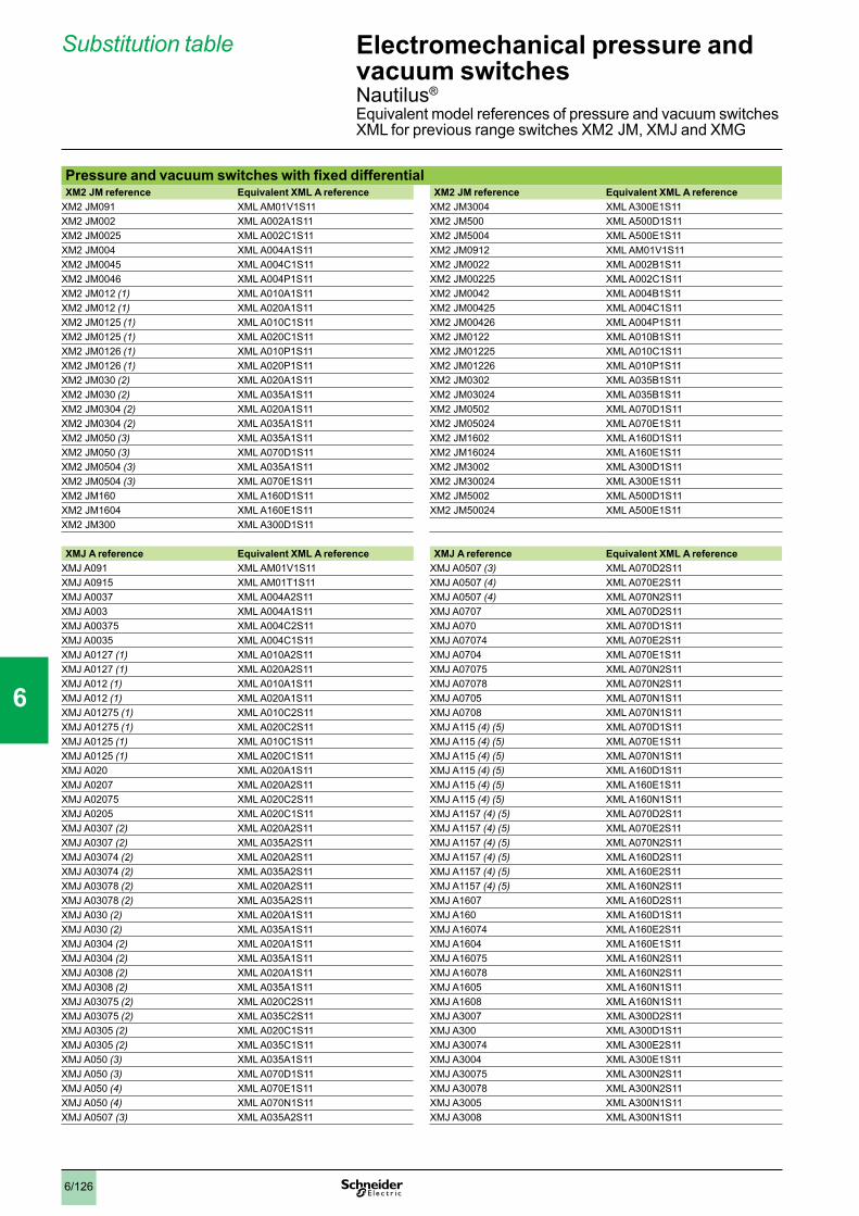
6/126
Substitution table
Pressure and vacuum switches with fixed differentialXM2 JM reference Equivalent XML A reference XM2 JM reference Equivalent XML A reference
XM2 JM091 XML AM01V1S11 XM2 JM3004 XML A300E1S11XM2 JM002 XML A002A1S11 XM2 JM500 XML A500D1S11XM2 JM0025 XML A002C1S11 XM2 JM5004 XML A500E1S11XM2 JM004 XML A004A1S11 XM2 JM0912 XML AM01V1S11XM2 JM0045 XML A004C1S11 XM2 JM0022 XML A002B1S11XM2 JM0046 XML A004P1S11 XM2 JM00225 XML A002C1S11XM2 JM012 (1) XML A010A1S11 XM2 JM0042 XML A004B1S11XM2 JM012 (1) XML A020A1S11 XM2 JM00425 XML A004C1S11XM2 JM0125 (1) XML A010C1S11 XM2 JM00426 XML A004P1S11XM2 JM0125 (1) XML A020C1S11 XM2 JM0122 XML A010B1S11XM2 JM0126 (1) XML A010P1S11 XM2 JM01225 XML A010C1S11XM2 JM0126 (1) XML A020P1S11 XM2 JM01226 XML A010P1S11XM2 JM030 (2) XML A020A1S11 XM2 JM0302 XML A035B1S11XM2 JM030 (2) XML A035A1S11 XM2 JM03024 XML A035B1S11XM2 JM0304 (2) XML A020A1S11 XM2 JM0502 XML A070D1S11XM2 JM0304 (2) XML A035A1S11 XM2 JM05024 XML A070E1S11XM2 JM050 (3) XML A035A1S11 XM2 JM1602 XML A160D1S11XM2 JM050 (3) XML A070D1S11 XM2 JM16024 XML A160E1S11XM2 JM0504 (3) XML A035A1S11 XM2 JM3002 XML A300D1S11XM2 JM0504 (3) XML A070E1S11 XM2 JM30024 XML A300E1S11XM2 JM160 XML A160D1S11 XM2 JM5002 XML A500D1S11XM2 JM1604 XML A160E1S11 XM2 JM50024 XML A500E1S11XM2 JM300 XML A300D1S11
XMJ A reference Equivalent XML A reference XMJ A reference Equivalent XML A referenceXMJ A091 XML AM01V1S11 XMJ A0507 (3) XML A070D2S11XMJ A0915 XML AM01T1S11 XMJ A0507 (4) XML A070E2S11XMJ A0037 XML A004A2S11 XMJ A0507 (4) XML A070N2S11XMJ A003 XML A004A1S11 XMJ A0707 XML A070D2S11XMJ A00375 XML A004C2S11 XMJ A070 XML A070D1S11XMJ A0035 XML A004C1S11 XMJ A07074 XML A070E2S11XMJ A0127 (1) XML A010A2S11 XMJ A0704 XML A070E1S11XMJ A0127 (1) XML A020A2S11 XMJ A07075 XML A070N2S11XMJ A012 (1) XML A010A1S11 XMJ A07078 XML A070N2S11XMJ A012 (1) XML A020A1S11 XMJ A0705 XML A070N1S11XMJ A01275 (1) XML A010C2S11 XMJ A0708 XML A070N1S11XMJ A01275 (1) XML A020C2S11 XMJ A115 (4) (5) XML A070D1S11XMJ A0125 (1) XML A010C1S11 XMJ A115 (4) (5) XML A070E1S11XMJ A0125 (1) XML A020C1S11 XMJ A115 (4) (5) XML A070N1S11XMJ A020 XML A020A1S11 XMJ A115 (4) (5) XML A160D1S11XMJ A0207 XML A020A2S11 XMJ A115 (4) (5) XML A160E1S11XMJ A02075 XML A020C2S11 XMJ A115 (4) (5) XML A160N1S11XMJ A0205 XML A020C1S11 XMJ A1157 (4) (5) XML A070D2S11XMJ A0307 (2) XML A020A2S11 XMJ A1157 (4) (5) XML A070E2S11XMJ A0307 (2) XML A035A2S11 XMJ A1157 (4) (5) XML A070N2S11XMJ A03074 (2) XML A020A2S11 XMJ A1157 (4) (5) XML A160D2S11XMJ A03074 (2) XML A035A2S11 XMJ A1157 (4) (5) XML A160E2S11XMJ A03078 (2) XML A020A2S11 XMJ A1157 (4) (5) XML A160N2S11XMJ A03078 (2) XML A035A2S11 XMJ A1607 XML A160D2S11XMJ A030 (2) XML A020A1S11 XMJ A160 XML A160D1S11XMJ A030 (2) XML A035A1S11 XMJ A16074 XML A160E2S11XMJ A0304 (2) XML A020A1S11 XMJ A1604 XML A160E1S11XMJ A0304 (2) XML A035A1S11 XMJ A16075 XML A160N2S11XMJ A0308 (2) XML A020A1S11 XMJ A16078 XML A160N2S11XMJ A0308 (2) XML A035A1S11 XMJ A1605 XML A160N1S11XMJ A03075 (2) XML A020C2S11 XMJ A1608 XML A160N1S11XMJ A03075 (2) XML A035C2S11 XMJ A3007 XML A300D2S11XMJ A0305 (2) XML A020C1S11 XMJ A300 XML A300D1S11XMJ A0305 (2) XML A035C1S11 XMJ A30074 XML A300E2S11XMJ A050 (3) XML A035A1S11 XMJ A3004 XML A300E1S11XMJ A050 (3) XML A070D1S11 XMJ A30075 XML A300N2S11XMJ A050 (4) XML A070E1S11 XMJ A30078 XML A300N2S11XMJ A050 (4) XML A070N1S11 XMJ A3005 XML A300N1S11XMJ A0507 (3) XML A035A2S11 XMJ A3008 XML A300N1S11
Electromechanical pressure and vacuum switches 0 Nautilus®
Equivalent model references of pressure and vacuum switches XML for previous range switches XM2 JM, XMJ and XMG
1
2
3
4
5
6
7
8
9
10
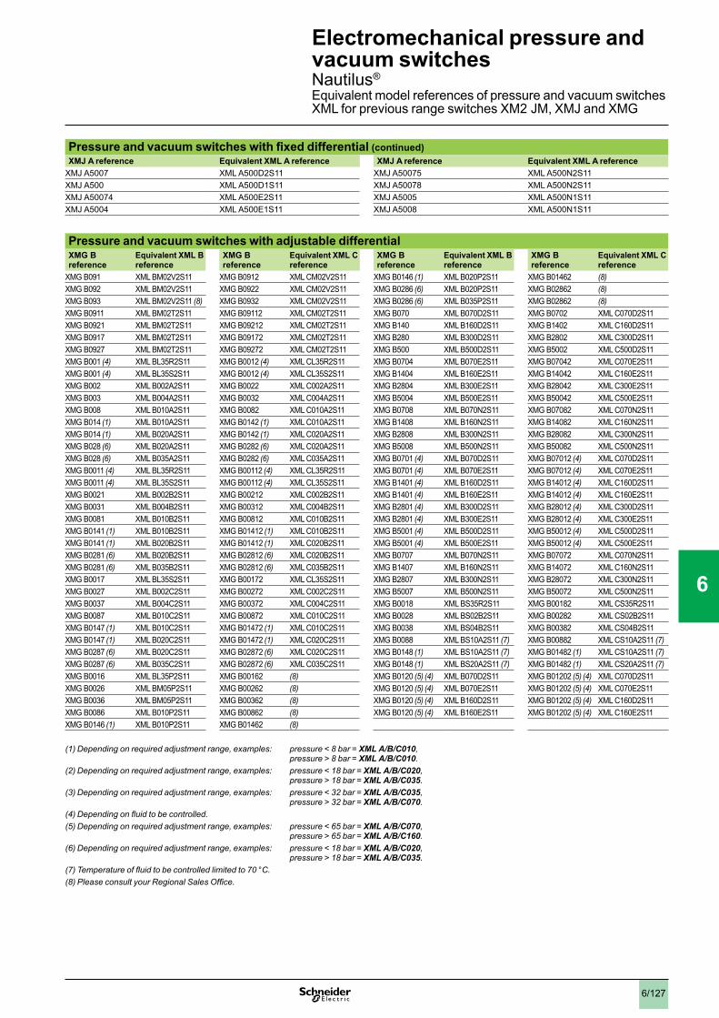
6/127
Pressure and vacuum switches with fixed differential (continued)XMJ A reference Equivalent XML A reference XMJ A reference Equivalent XML A reference
XMJ A5007 XML A500D2S11 XMJ A50075 XML A500N2S11XMJ A500 XML A500D1S11 XMJ A50078 XML A500N2S11XMJ A50074 XML A500E2S11 XMJ A5005 XML A500N1S11XMJ A5004 XML A500E1S11 XMJ A5008 XML A500N1S11
Pressure and vacuum switches with adjustable differentialXMG B reference
Equivalent XML B reference
XMG B reference
Equivalent XML C reference
XMG B reference
Equivalent XML B reference
XMG B reference
Equivalent XML C reference
XMG B091 XML BM02V2S11 XMG B0912 XML CM02V2S11 XMG B0146 (1) XML B020P2S11 XMG B01462 (8)XMG B092 XML BM02V2S11 XMG B0922 XML CM02V2S11 XMG B0286 (6) XML B020P2S11 XMG B02862 (8)XMG B093 XML BM02V2S11 (8) XMG B0932 XML CM02V2S11 XMG B0286 (6) XML B035P2S11 XMG B02862 (8)XMG B0911 XML BM02T2S11 XMG B09112 XML CM02T2S11 XMG B070 XML B070D2S11 XMG B0702 XML C070D2S11XMG B0921 XML BM02T2S11 XMG B09212 XML CM02T2S11 XMG B140 XML B160D2S11 XMG B1402 XML C160D2S11XMG B0917 XML BM02T2S11 XMG B09172 XML CM02T2S11 XMG B280 XML B300D2S11 XMG B2802 XML C300D2S11XMG B0927 XML BM02T2S11 XMG B09272 XML CM02T2S11 XMG B500 XML B500D2S11 XMG B5002 XML C500D2S11XMG B001 (4) XML BL35R2S11 XMG B0012 (4) XML CL35R2S11 XMG B0704 XML B070E2S11 XMG B07042 XML C070E2S11XMG B001 (4) XML BL35S2S11 XMG B0012 (4) XML CL35S2S11 XMG B1404 XML B160E2S11 XMG B14042 XML C160E2S11XMG B002 XML B002A2S11 XMG B0022 XML C002A2S11 XMG B2804 XML B300E2S11 XMG B28042 XML C300E2S11XMG B003 XML B004A2S11 XMG B0032 XML C004A2S11 XMG B5004 XML B500E2S11 XMG B50042 XML C500E2S11XMG B008 XML B010A2S11 XMG B0082 XML C010A2S11 XMG B0708 XML B070N2S11 XMG B07082 XML C070N2S11XMG B014 (1) XML B010A2S11 XMG B0142 (1) XML C010A2S11 XMG B1408 XML B160N2S11 XMG B14082 XML C160N2S11XMG B014 (1) XML B020A2S11 XMG B0142 (1) XML C020A2S11 XMG B2808 XML B300N2S11 XMG B28082 XML C300N2S11XMG B028 (6) XML B020A2S11 XMG B0282 (6) XML C020A2S11 XMG B5008 XML B500N2S11 XMG B50082 XML C500N2S11XMG B028 (6) XML B035A2S11 XMG B0282 (6) XML C035A2S11 XMG B0701 (4) XML B070D2S11 XMG B07012 (4) XML C070D2S11XMG B0011 (4) XML BL35R2S11 XMG B00112 (4) XML CL35R2S11 XMG B0701 (4) XML B070E2S11 XMG B07012 (4) XML C070E2S11XMG B0011 (4) XML BL35S2S11 XMG B00112 (4) XML CL35S2S11 XMG B1401 (4) XML B160D2S11 XMG B14012 (4) XML C160D2S11XMG B0021 XML B002B2S11 XMG B00212 XML C002B2S11 XMG B1401 (4) XML B160E2S11 XMG B14012 (4) XML C160E2S11XMG B0031 XML B004B2S11 XMG B00312 XML C004B2S11 XMG B2801 (4) XML B300D2S11 XMG B28012 (4) XML C300D2S11XMG B0081 XML B010B2S11 XMG B00812 XML C010B2S11 XMG B2801 (4) XML B300E2S11 XMG B28012 (4) XML C300E2S11XMG B0141 (1) XML B010B2S11 XMG B01412 (1) XML C010B2S11 XMG B5001 (4) XML B500D2S11 XMG B50012 (4) XML C500D2S11XMG B0141 (1) XML B020B2S11 XMG B01412 (1) XML C020B2S11 XMG B5001 (4) XML B500E2S11 XMG B50012 (4) XML C500E2S11XMG B0281 (6) XML B020B2S11 XMG B02812 (6) XML C020B2S11 XMG B0707 XML B070N2S11 XMG B07072 XML C070N2S11XMG B0281 (6) XML B035B2S11 XMG B02812 (6) XML C035B2S11 XMG B1407 XML B160N2S11 XMG B14072 XML C160N2S11XMG B0017 XML BL35S2S11 XMG B00172 XML CL35S2S11 XMG B2807 XML B300N2S11 XMG B28072 XML C300N2S11XMG B0027 XML B002C2S11 XMG B00272 XML C002C2S11 XMG B5007 XML B500N2S11 XMG B50072 XML C500N2S11XMG B0037 XML B004C2S11 XMG B00372 XML C004C2S11 XMG B0018 XML BS35R2S11 XMG B00182 XML CS35R2S11XMG B0087 XML B010C2S11 XMG B00872 XML C010C2S11 XMG B0028 XML BS02B2S11 XMG B00282 XML CS02B2S11XMG B0147 (1) XML B010C2S11 XMG B01472 (1) XML C010C2S11 XMG B0038 XML BS04B2S11 XMG B00382 XML CS04B2S11XMG B0147 (1) XML B020C2S11 XMG B01472 (1) XML C020C2S11 XMG B0088 XML BS10A2S11 (7) XMG B00882 XML CS10A2S11 (7)XMG B0287 (6) XML B020C2S11 XMG B02872 (6) XML C020C2S11 XMG B0148 (1) XML BS10A2S11 (7) XMG B01482 (1) XML CS10A2S11 (7)XMG B0287 (6) XML B035C2S11 XMG B02872 (6) XML C035C2S11 XMG B0148 (1) XML BS20A2S11 (7) XMG B01482 (1) XML CS20A2S11 (7)XMG B0016 XML BL35P2S11 XMG B00162 (8) XMG B0120 (5) (4) XML B070D2S11 XMG B01202 (5) (4) XML C070D2S11XMG B0026 XML BM05P2S11 XMG B00262 (8) XMG B0120 (5) (4) XML B070E2S11 XMG B01202 (5) (4) XML C070E2S11XMG B0036 XML BM05P2S11 XMG B00362 (8) XMG B0120 (5) (4) XML B160D2S11 XMG B01202 (5) (4) XML C160D2S11XMG B0086 XML B010P2S11 XMG B00862 (8) XMG B0120 (5) (4) XML B160E2S11 XMG B01202 (5) (4) XML C160E2S11XMG B0146 (1) XML B010P2S11 XMG B01462 (8)
(1)Dependingonrequiredadjustmentrange,examples: pressure < 8 bar = XML A/B/C010,pressure > 8 bar = XML A/B/C010.
(2)Dependingonrequiredadjustmentrange,examples: pressure < 18 bar = XML A/B/C020,pressure > 18 bar = XML A/B/C035.
(3)Dependingonrequiredadjustmentrange,examples: pressure < 32 bar = XML A/B/C035,pressure > 32 bar = XML A/B/C070.
(4)Dependingonfluidtobecontrolled.(5)Dependingonrequiredadjustmentrange,examples: pressure < 65 bar = XML A/B/C070,
pressure > 65 bar = XML A/B/C160.(6)Dependingonrequiredadjustmentrange,examples: pressure < 18 bar = XML A/B/C020,
pressure > 18 bar = XML A/B/C035.(7)Temperatureoffluidtobecontrolledlimitedto70°C.(8)PleaseconsultyourRegionalSalesOffice.
Electromechanical pressure and vacuum switches 0 Nautilus®
Equivalent model references of pressure and vacuum switches XML for previous range switches XM2 JM, XMJ and XMG
1
2
3
4
5
6
7
8
9
10

6/128
This information will assist in checking the corrosion resistance of the pressure or vacuum switches in relation to the fluids controlled
Component materials of unitsincontactwithfluid
Component materials in contact with fluidPressure or vacuum switch reference Zinc alloy Stainless
steelBrass Steel Nitrile PTFE FPM, FKM Aluminium
XML AM01Vpppp, XML pM02Vpppp (1)
XML AM01Tpppp, XML pM02Tpppp (2)
XML BM03Rpppp
XML BM03Spppp (3)
XML pM05Apppp (1)
XML pM05Bpppp (1)
XML pM05Cpppp (1)
XML BM05Ppppp (1)
XML BL05Rpppp
XML BL05Spppp (3)
XML pL35Rpppp, XML pS35Rpppp (1)
XML pL35Spppp (3)
XML BL35Ppppp (1)
XML p001Rpppp (1)
XML p001Spppp (3)
XML B001Ppppp (1)
XML p002Apppp
XML p002Bpppp, XML pS02Bpppp
XML p002Cpppp (3)
XML A004Apppp
XML A004Bpppp
XML A004Cpppp (2)
XML A004Ppppp
Materials in contact with fluid
(1) 1.4307 (AISI 316L)(2) 1.4404 (AISI 316L)(3) 1.4305 (AISI 303)
Electromechanical pressure and vacuum switches 0 Nautilus® type XML
1
2
3
4
5
6
7
8
9
10
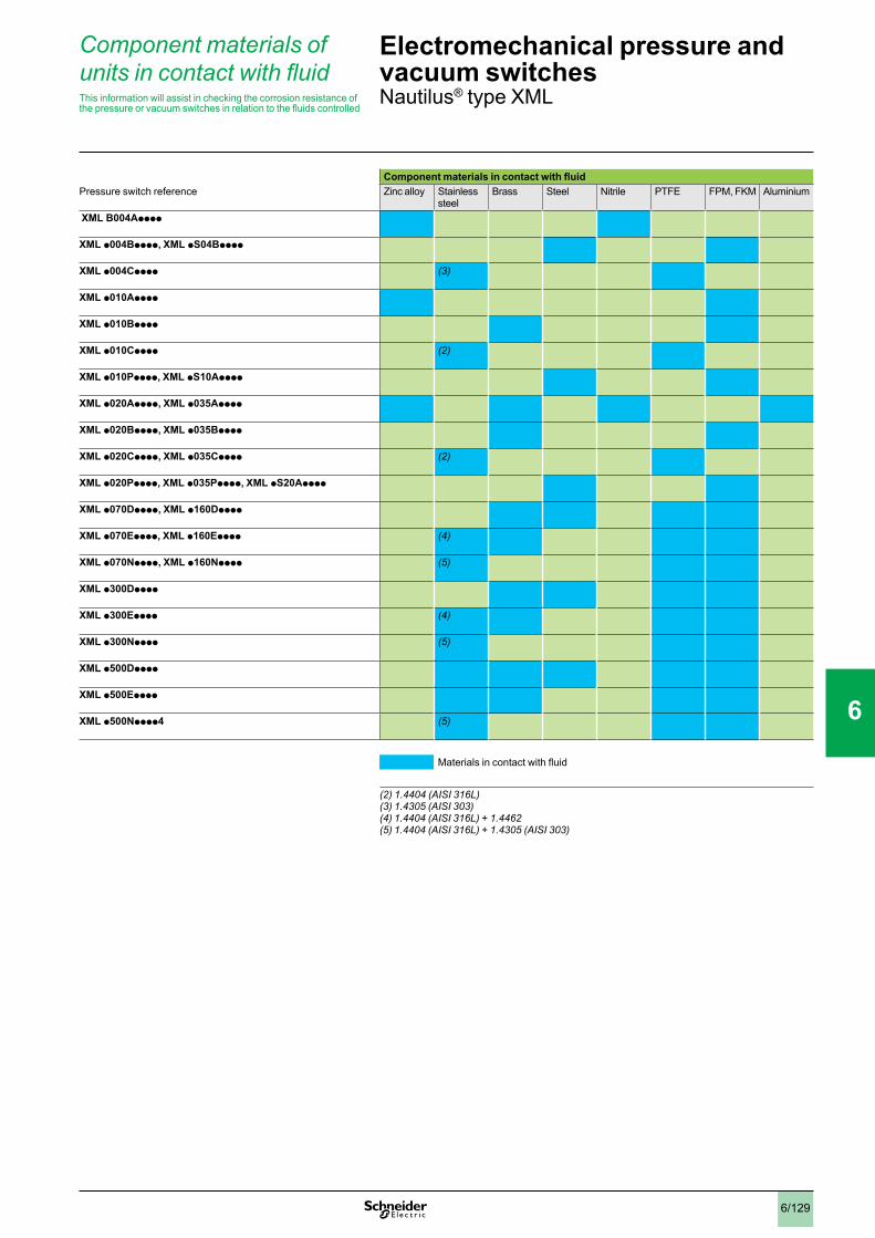
6/129
This information will assist in checking the corrosion resistance of the pressure or vacuum switches in relation to the fluids controlled
Component materials of unitsincontactwithfluid
Component materials in contact with fluidPressure switch reference Zinc alloy Stainless
steelBrass Steel Nitrile PTFE FPM, FKM Aluminium
XML B004Apppp
XML p004Bpppp, XML pS04Bpppp
XML p004Cpppp (3)
XML p010Apppp
XML p010Bpppp
XML p010Cpppp (2)
XML p010Ppppp, XML pS10Apppp
XML p020Apppp, XML p035Apppp
XML p020Bpppp, XML p035Bpppp
XML p020Cpppp, XML p035Cpppp (2)
XML p020Ppppp, XML p035Ppppp, XML pS20Apppp
XML p070Dpppp, XML p160Dpppp
XML p070Epppp, XML p160Epppp (4)
XML p070Npppp, XML p160Npppp (5)
XML p300Dpppp
XML p300Epppp (4)
XML p300Npppp (5)
XML p500Dpppp
XML p500Epppp
XML p500Npppp4 (5)
Materials in contact with fluid (2) 1.4404 (AISI 316L)(3) 1.4305 (AISI 303)(4) 1.4404 (AISI 316L) + 1.4462(5) 1.4404 (AISI 316L) + 1.4305 (AISI 303)
Electromechanical pressure and vacuum switches 0 Nautilus® type XML
1
2
3
4
5
6
7
8
9
10
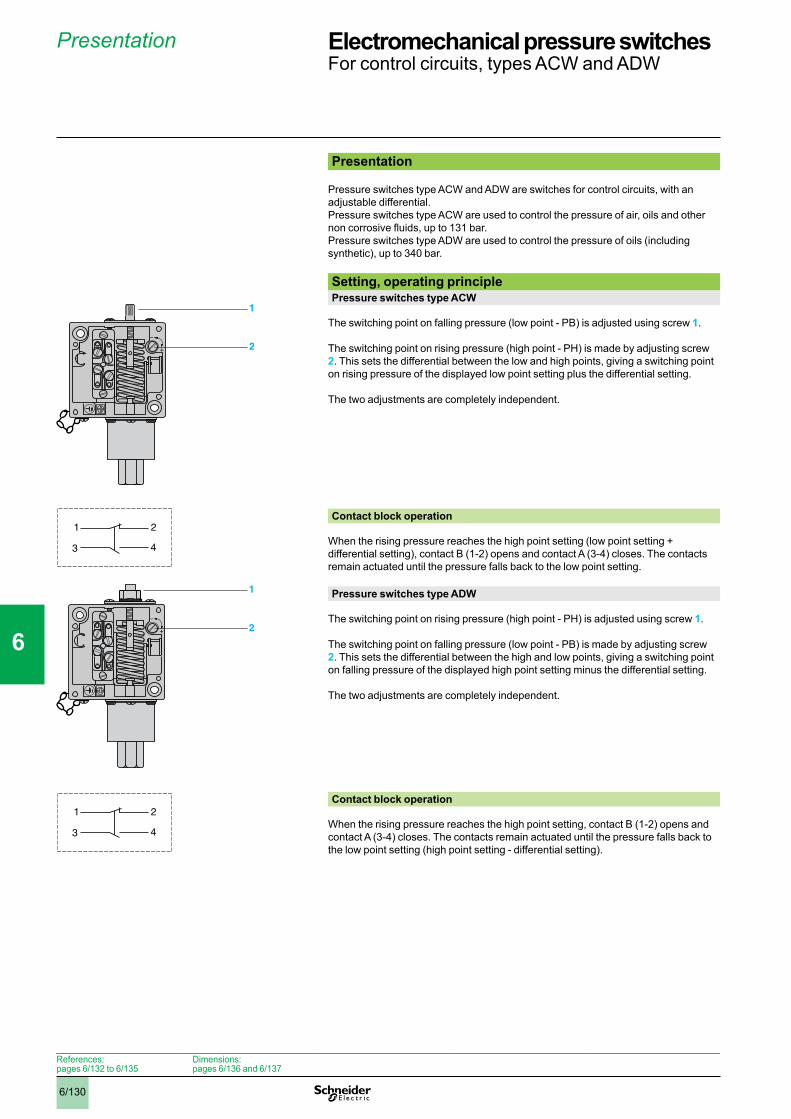
6/130
Presentation
Presentation
Pressure switches type ACW and ADW are switches for control circuits, with an adjustable differential.Pressure switches type ACW are used to control the pressure of air, oils and other non corrosive fluids, up to 131 bar.Pressure switches type ADW are used to control the pressure of oils (including synthetic), up to 340 bar. Setting, operating principlePressure switches type ACW
The switching point on falling pressure (low point - PB) is adjusted using screw 1.
The switching point on rising pressure (high point - PH) is made by adjusting screw 2. This sets the differential between the low and high points, giving a switching point on rising pressure of the displayed low point setting plus the differential setting.
The two adjustments are completely independent.
Contact block operation
When the rising pressure reaches the high point setting (low point setting + differential setting), contact B (1-2) opens and contact A (3-4) closes. The contacts remain actuated until the pressure falls back to the low point setting.
Pressure switches type ADW
The switching point on rising pressure (high point - PH) is adjusted using screw 1.
The switching point on falling pressure (low point - PB) is made by adjusting screw 2. This sets the differential between the high and low points, giving a switching point on falling pressure of the displayed high point setting minus the differential setting.
The two adjustments are completely independent.
Contact block operation
When the rising pressure reaches the high point setting, contact B (1-2) opens and contact A (3-4) closes. The contacts remain actuated until the pressure falls back to the low point setting (high point setting - differential setting).
+
–
1
2
1 2
3 4
+
–
1
2
1 2
3 4
References: pages 6/132 to 6/135
Dimensions: pages 6/136 and 6/137
Electromechanical pressure switches 0 For control circuits, types ACW and ADW
1
2
3
4
5
6
7
8
9
10

6/131
Characteristics
Environmental characteristicsPressure switch type ACW (bellows operated) ADW (piston operated)
Conformity to standards e, IEC/EN 60947-5-1
Product certifications CSA, UL (Recognized)
Protective treatment “TC”
Materials Zinc alloy casePhosphor bronze bellows
Zinc alloy casePressure switches with drainage hole: Buna N diaphragm, steel piston, cast iron cylinder Pressure switches with Quad-Ring piston seal: Buna N diaphragm, Teflon and Viton seal, stainless steel piston and cylinder
Ambient air temperature (for operation) °C - 56…+ 85 - 30…+ 85
Fluids controlled Air, oils and other non corrosive fluids, from - 73 to + 125 °C
Oils and other fluids, from - 25 to + 120 °C (for ADW 5, 6, 7S1, 25, 26, 27S1)
Oils (including synthetic) only, from - 30 to + 125 °C (for ADW 3, 4, 7, 23, 24, 27)
Degree of protection IP 65 conforming to IEC/EN 60529
Fluid connection G 1/4 (BSP female) conforming to NF E 03-005, ISO 228
G 3/8 (BSP female) conforming to NF E 03-005, ISO 228
Electrical connection Terminals. 1 tapped entry for n° 13 (DIN Pg 13.5) cable gland
Contact block characteristicsRated operational current
Category AC-15Ue24 V110 V220 V500 V
1 C/O single-pole pressure switches
Ie5 A5 A3 A1.4 A
2 C/O single-pole pressure switches
Ie3 A3 A1.5 A0.7 A
Category DC-13 Ue24 V110 V220 V500 V600 V
Ie5 A0.5 A0.25 A0.10 A0.06 A
Ie1.5 A0.25 A–––
Short-circuit protection 10 A cartridge fuse type gG
Connection Screw terminalsMinimum clamping capacity: 1 x 1 mm2
Maximum clamping capacity: 2 x 2.5 mm2
References: pages 6/132 to 6/135
Dimensions: pages 6/136 and 6/137
Electromechanical pressure switches 0 For control circuits, types ACW and ADW
1
2
3
4
5
6
7
8
9
10
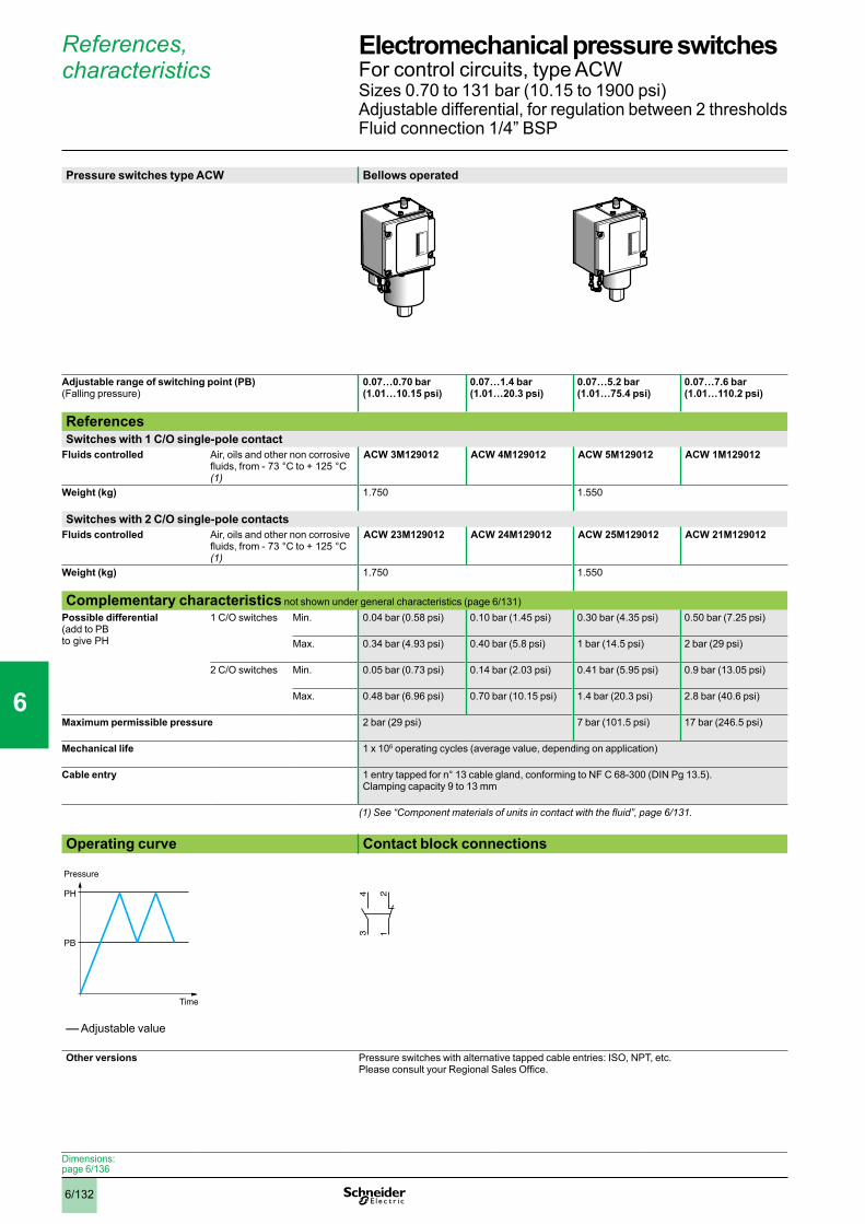
6/132
References, characteristics
Pressure switches type ACW Bellows operated
Adjustable range of switching point (PB)(Falling pressure)
0.07…0.70 bar(1.01…10.15 psi)
0.07…1.4 bar(1.01…20.3 psi)
0.07…5.2 bar(1.01…75.4 psi)
0.07…7.6 bar(1.01…110.2 psi)
ReferencesSwitches with 1 C/O single-pole contact
Fluids controlled Air, oils and other non corrosive fluids, from - 73 °C to + 125 °C (1)
ACW 3M129012 ACW 4M129012 ACW 5M129012 ACW 1M129012
Weight (kg) 1.750 1.550
Switches with 2 C/O single-pole contactsFluids controlled Air, oils and other non corrosive
fluids, from - 73 °C to + 125 °C (1)
ACW 23M129012 ACW 24M129012 ACW 25M129012 ACW 21M129012
Weight (kg) 1.750 1.550
Complementary characteristics not shown under general characteristics (page 6/131) Possible differential (add to PB to give PH
1 C/O switches Min. 0.04 bar (0.58 psi) 0.10 bar (1.45 psi) 0.30 bar (4.35 psi) 0.50 bar (7.25 psi)
Max. 0.34 bar (4.93 psi) 0.40 bar (5.8 psi) 1 bar (14.5 psi) 2 bar (29 psi)
2 C/O switches Min. 0.05 bar (0.73 psi) 0.14 bar (2.03 psi) 0.41 bar (5.95 psi) 0.9 bar (13.05 psi)
Max. 0.48 bar (6.96 psi) 0.70 bar (10.15 psi) 1.4 bar (20.3 psi) 2.8 bar (40.6 psi)
Maximum permissible pressure 2 bar (29 psi) 7 bar (101.5 psi) 17 bar (246.5 psi)
Mechanical life 1 x 10⁶ operating cycles (average value, depending on application)
Cable entry 1 entry tapped for n° 13 cable gland, conforming to NF C 68-300 (DIN Pg 13.5). Clamping capacity 9 to 13 mm
(1)See“Componentmaterialsofunitsincontactwiththefluid”,page6/131.
Operating curve Contact block connections
–– Adjustable value
Other versions Pressure switches with alternative tapped cable entries: ISO, NPT, etc. Please consult your Regional Sales Office.
MINI
MAXI
MINI
MAXI
PH
PB
Time
Pressure
12
34
Dimensions: page 6/136
Electromechanical pressure switches 0 For control circuits, type ACWSizes 0.70 to 131 bar (10.15 to 1900 psi)Adjustable differential, for regulation between 2 thresholdsFluid connection 1/4” BSP
1
2
3
4
5
6
7
8
9
10
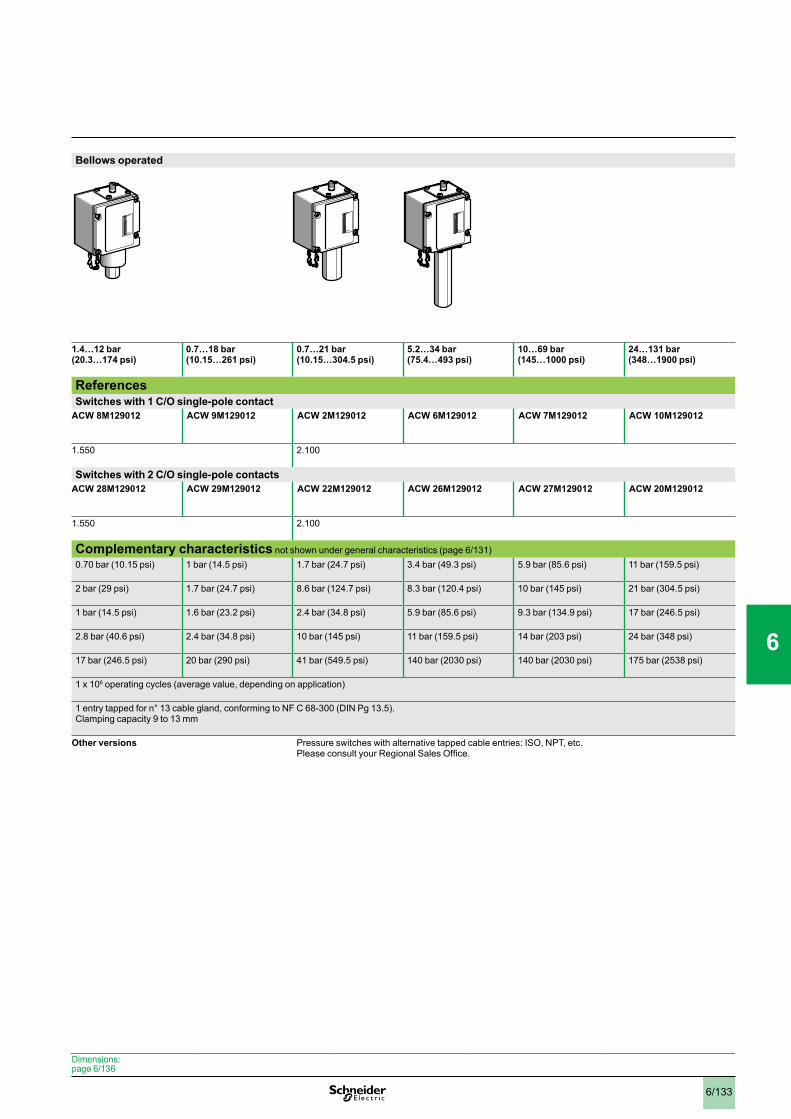
6/133
Bellows operated
1.4…12 bar(20.3…174 psi)
0.7…18 bar(10.15…261 psi)
0.7…21 bar(10.15…304.5 psi)
5.2…34 bar(75.4…493 psi)
10…69 bar(145…1000 psi)
24…131 bar(348…1900 psi)
ReferencesSwitches with 1 C/O single-pole contact
ACW 8M129012 ACW 9M129012 ACW 2M129012 ACW 6M129012 ACW 7M129012 ACW 10M129012
1.550 2.100
Switches with 2 C/O single-pole contactsACW 28M129012 ACW 29M129012 ACW 22M129012 ACW 26M129012 ACW 27M129012 ACW 20M129012
1.550 2.100
Complementary characteristics not shown under general characteristics (page 6/131) 0.70 bar (10.15 psi) 1 bar (14.5 psi) 1.7 bar (24.7 psi) 3.4 bar (49.3 psi) 5.9 bar (85.6 psi) 11 bar (159.5 psi)
2 bar (29 psi) 1.7 bar (24.7 psi) 8.6 bar (124.7 psi) 8.3 bar (120.4 psi) 10 bar (145 psi) 21 bar (304.5 psi)
1 bar (14.5 psi) 1.6 bar (23.2 psi) 2.4 bar (34.8 psi) 5.9 bar (85.6 psi) 9.3 bar (134.9 psi) 17 bar (246.5 psi)
2.8 bar (40.6 psi) 2.4 bar (34.8 psi) 10 bar (145 psi) 11 bar (159.5 psi) 14 bar (203 psi) 24 bar (348 psi)
17 bar (246.5 psi) 20 bar (290 psi) 41 bar (549.5 psi) 140 bar (2030 psi) 140 bar (2030 psi) 175 bar (2538 psi)
1 x 10⁶ operating cycles (average value, depending on application)
1 entry tapped for n° 13 cable gland, conforming to NF C 68-300 (DIN Pg 13.5). Clamping capacity 9 to 13 mm
Other versions Pressure switches with alternative tapped cable entries: ISO, NPT, etc. Please consult your Regional Sales Office.
MINI
MAXI
MINI
MAXI
MINI
MAXI
Dimensions: page 6/136
0
1
2
3
4
5
6
7
8
9
10

6/134
References, characteristics
Pressure switches type ADW Piston operated, with drainage hole (1)
Adjustable range of switching point (PH)(Rising pressure)
9.3…69 bar(135…1000 psi)
28…210 bar(406…3045 psi)
38…340 bar(551…4930 psi)
ReferencesSwitches with 1 C/O single-pole contact
Fluids controlled Oils (including synthetic), from - 30 °C to + 125 °C (2) (3)
ADW 3M129012 ADW 4M129012 ADW 7M129012
Weight (kg) 1.880
Switches with 2 C/O single-pole contactsFluids controlled Oils (including synthetic),
from - 30 °C to + 125 °C (2) (3) ADW 23M129012 ADW 24M129012 ADW 27M129012
Weight (kg) 1.880
Complementary characteristics not shown under general characteristics (page 6/131) Possible differential (subtract from PH to give PB)
1 C/O switches Min. 2.4 bar (34.8 psi) 6.9 bar (100 psi) 8.6 bar (124.7 psi)
Max. 9.3 bar (135 psi) 28 bar (406 psi) 38 bar (551 psi)
2 C/O switches Min. 3.1 bar (45 psi) 8.6 bar (124.7 psi) 14 bar (203 psi)
Max. 14 bar (203 psi) 34 bar (493 psi) 41 bar (594.5 psi)
Maximum permissible pressure 690 bar (10 000 psi)
Mechanical life 1 x 10⁶ operating cycles (average value, depending on application)
Cable entry 1 entry tapped for n° 13 cable gland, conforming to NF C 68-300 (DIN Pg 13.5). Clamping capacity 9 to 13 mm
(1) Since it is normal for piston type pressure switches (not incorporating a piston seal) to have aslightoilleakagepastthepiston,adrainholethroughthecylinderwallisincorporated.To
avoid back pressure, this hole should never be plugged. If for any reason this oil leakage is undesirable, use pressure switches incorporating a Quad-Ring piston seal.
(2)See“Componentmaterialsofunitsincontactwiththefluid”,page6/131.(3)Onlyforcontrolofgroup2fluids,inaccordancewithdirective97/23/EEC.
Operating curve Contact block connections
–– Adjustable value
Other versions Pressure switches with alternative tapped cable entries: ISO, NPT, etc. Please consult your Regional Sales Office.
MINI
MAXI
PH
PB
Time
Pressure
12
34
Dimensions: page 6/136
Electromechanical pressure switches 0 For control circuits, type ADWSizes 69 to 340 bar (1000 to 4930 psi)Adjustable differential, for regulation between 2 thresholdsFluid connection 3/8” BSP
1
2
3
4
5
6
7
8
9
10
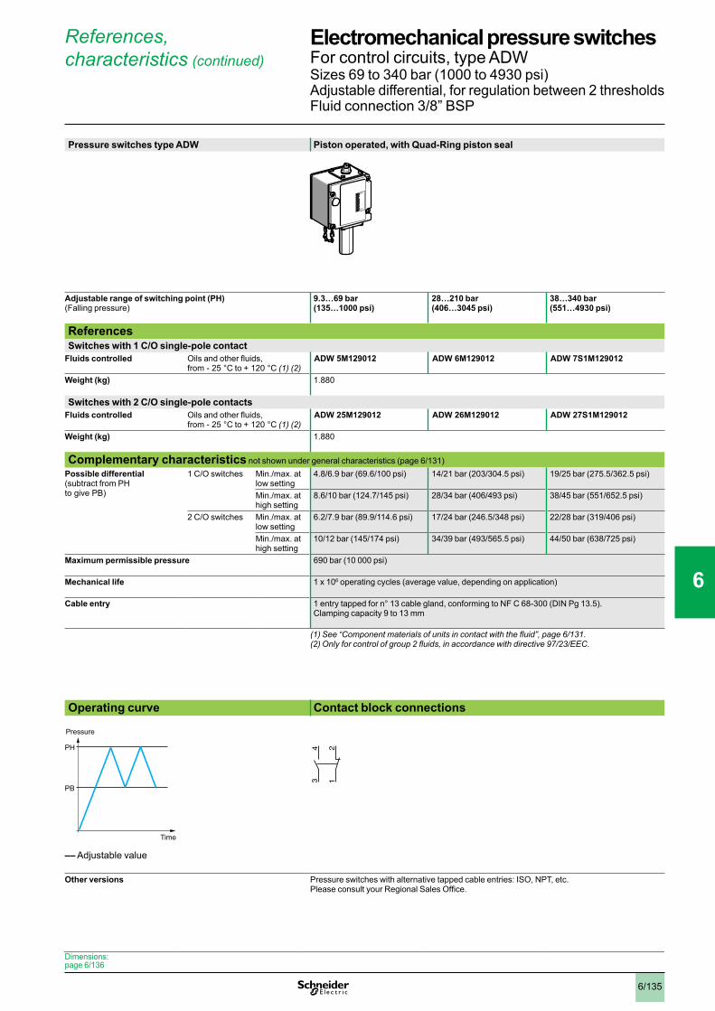
6/135
References, characteristics (continued)
Pressure switches type ADW Piston operated, with Quad-Ring piston seal
Adjustable range of switching point (PH)(Falling pressure)
9.3…69 bar(135…1000 psi)
28…210 bar(406…3045 psi)
38…340 bar(551…4930 psi)
ReferencesSwitches with 1 C/O single-pole contact
Fluids controlled Oils and other fluids, from - 25 °C to + 120 °C (1) (2)
ADW 5M129012 ADW 6M129012 ADW 7S1M129012
Weight (kg) 1.880
Switches with 2 C/O single-pole contactsFluids controlled Oils and other fluids,
from - 25 °C to + 120 °C (1) (2) ADW 25M129012 ADW 26M129012 ADW 27S1M129012
Weight (kg) 1.880
Complementary characteristics not shown under general characteristics (page 6/131) Possible differential (subtract from PH to give PB)
1 C/O switches Min./max. at low setting
4.8/6.9 bar (69.6/100 psi) 14/21 bar (203/304.5 psi) 19/25 bar (275.5/362.5 psi)
Min./max. at high setting
8.6/10 bar (124.7/145 psi) 28/34 bar (406/493 psi) 38/45 bar (551/652.5 psi)
2 C/O switches Min./max. at low setting
6.2/7.9 bar (89.9/114.6 psi) 17/24 bar (246.5/348 psi) 22/28 bar (319/406 psi)
Min./max. at high setting
10/12 bar (145/174 psi) 34/39 bar (493/565.5 psi) 44/50 bar (638/725 psi)
Maximum permissible pressure 690 bar (10 000 psi)
Mechanical life 1 x 10⁶ operating cycles (average value, depending on application)
Cable entry 1 entry tapped for n° 13 cable gland, conforming to NF C 68-300 (DIN Pg 13.5). Clamping capacity 9 to 13 mm
(1)See“Componentmaterialsofunitsincontactwiththefluid”,page6/131.(2)Onlyforcontrolofgroup2fluids,inaccordancewithdirective97/23/EEC.
Operating curve Contact block connections
–– Adjustable value
Other versions Pressure switches with alternative tapped cable entries: ISO, NPT, etc. Please consult your Regional Sales Office.
MINI
MAXI
PH
PB
Time
Pressure
12
34
Dimensions: page 6/136
Electromechanical pressure switches 0 For control circuits, type ADWSizes 69 to 340 bar (1000 to 4930 psi)Adjustable differential, for regulation between 2 thresholdsFluid connection 3/8” BSP
1
2
3
4
5
6
7
8
9
10

6/136
Dimensions
ACW 3, 4, 23, 24 ACW 1, 5, 8, 9, 21, 25, 28, 29
(1)Tappedentryforn°13cablegland (1)Tappedentryforn°13cableglandØ: G 1/4 (BSP female) Ø: G 1/4 (BSP female)
ACW 2, 22 ACW 6, 7, 10, 26, 27, 20
(1)Tappedentryforn°13cablegland (1)Tappedentryforn°13cableglandØ: G 1/4 (BSP female) Ø: G 1/4 (BSP female)
31
31
68
699,
59,
5
31
31
(1)
18
6988
1788
190
9,5 9,5
31
31
68
699,
59,
5
31
31
(1)
18
6988
1788
167
9,5 9,5
31
31
68
699,
59,
5
31
31
(1)
18
6988
1788
173
9,5 9,5
31
31
699,
59,
5
31
31
(1)
69
1788
221
9,5 9,5
Characteristics:pages 6/131, 6/132 and 6/135
References:pages 6/132 and 6/133
Electromechanical pressure switches 0 For control circuits, type ACW
1
2
3
4
5
6
7
8
9
10
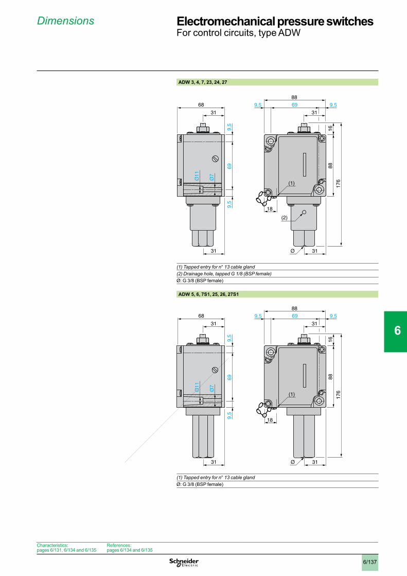
6/137
Dimensions
ADW 3, 4, 7, 23, 24, 27
(1)Tappedentryforn°13cablegland(2)Drainagehole,tappedG1/8(BSPfemale)Ø: G 3/8 (BSP female)
ADW 5, 6, 7S1, 25, 26, 27S1
(1)Tappedentryforn°13cableglandØ: G 3/8 (BSP female)
31
31
68
699,
59,
5
31
31
(1)
18
6988
1688
176
9,5 9,5
(2)
31
31
68
699,
59,
5
31
31
(1)
18
6988
1688
176
9,5 9,5
Characteristics:pages 6/131, 6/134 and 6/135
References:pages 6/134 and 6/135
Electromechanical pressure switches 0 For control circuits, type ADW
1
2
3
4
5
6
7
8
9
10
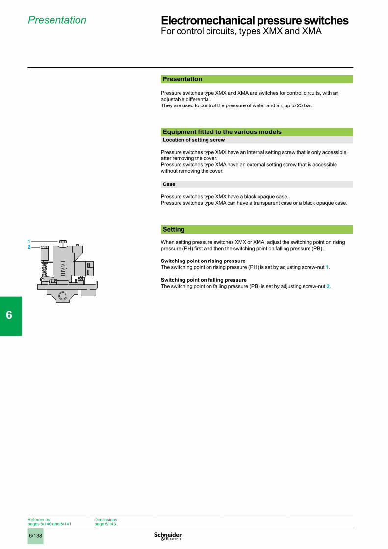
6/138
Presentation
Presentation
Pressure switches type XMX and XMA are switches for control circuits, with an adjustable differential.They are used to control the pressure of water and air, up to 25 bar.
Equipment fitted to the various modelsLocation of setting screw
Pressure switches type XMX have an internal setting screw that is only accessible after removing the cover.Pressure switches type XMA have an external setting screw that is accessible without removing the cover.
Case
Pressure switches type XMX have a black opaque case.Pressure switches type XMA can have a transparent case or a black opaque case.
Setting
When setting pressure switches XMX or XMA, adjust the switching point on rising pressure (PH) first and then the switching point on falling pressure (PB).
Switching point on rising pressureThe switching point on rising pressure (PH) is set by adjusting screw-nut 1.
Switching point on falling pressureThe switching point on falling pressure (PB) is set by adjusting screw-nut 2.
12
References:pages 6/140 and 6/141
Dimensions: page 6/143
Electromechanical pressure switches 0 For control circuits, types XMX and XMA
1
2
3
4
5
6
7
8
9
10
6/139
Characteristics
Environmental characteristicsConformity to standards e, IEC/EN 60947-5-1
Product certifications UL, CSA, ccc
Protective treatment “TC”
Ambient air temperature °C For operation: - 25…+ 70 for 6 and 25 bar versions- 25…+ 55 for 12 bar versions
For storage: - 40…+ 70 Fluids controlled °C Air, fresh water, sea water: 0…+ 70 °C for 6 and 25 bar versions
0…+ 55 °C for 12 bar versions
Materials Case: polycarbonate impregnated with Lexan 500R fibreglass (black opaque cover) or polycarbonate impregnated with Lexan 123 fibreglass (transparent cover) Component materials in contact with fluid: chromated zinc alloy (fluid entry), canvas covered nitrile (diaphragm)
Operating position All positions
Electric shock protection Class I conforming to IEC 536
Degree of protection IP 54 conforming to IEC/EN 60529
Operating rate Op.cycles/h
600
Repeat accuracy < 3.5%
Fluid connection G 1/4 or 4 x G 1/4 (BSP female) conforming to NF E 03-005, ISO 228
Electrical connection Terminals2 tapped entries for n° 13 (DIN Pg 13.5) cable gland
Contact block characteristicsRated operational characteristics a AC-15, B300 (Ue = 240 V, Ie = 1.5 A; Ue = 120 V, Ie = 3 A)
c DC-13, R300 (Ue = 250 V, Ie = 0.1 A)
Rated insulation voltage V Ui = 500 conforming to IEC/EN 60947-1
Rated impulse withstand voltage kV U imp = 6 conforming to IEC/EN 60947-1
Type of contacts 1 C/O single-pole contact, snap action
Terminal referencing Conforming to CENELEC EN 50013
Short-circuit protection 10 A cartridge fuse type gG (gI)
Connection Screw clamp terminalsMinimum clamping capacity: 1 x 1 mm2
Maximum clamping capacity: 2 x 2.5 mm2
Electrical durability a.c. supply 50/60 Hz, Ith = 10 AInductive circuit, utilisation category AC-15, 3 A/240 V: 1 million operating cycles
References:pages 6/140 and 6/141
Dimensions: page 6/143
Electromechanical pressure switches 0 For control circuits, types XMX and XMA
1
2
3
4
5
6
7
8
9
10

6/140
References, characteristics
Pressure switches type XMX (internal setting screw)
Adjustable range of switching point (PH) (Rising pressure)
1…6 bar(14.5…87 psi)
1.3…12 bar(18.85…174 psi)
3.5…25 bar(50.75…362.5 psi)
1…6 bar(14.5…87 psi)
1.3…12 bar(18.85…174 psi)
3.5…25 bar(50.75…362.5 psi)
Fluid connection G 1/4 (BSP female) 4 x G 1/4 (BSP female)
ReferencesSwitches with black opaque cover
Fluids controlled Air, fresh water, sea water (1)
XMX A06L2135 XMX A12L2135 XMX A25L2135 XMX A06L2435 XMX A12L2435 XMX A25L2435
Weight (kg) 0.430 0.650 0.430 0.650
Complementary characteristics not shown under general characteristics (page 6/139)Possible differential (subtract from PH to give PB)
Min. at low setting 0.8 bar (11.6 psi) 1 bar (14.5 psi) 3.4 bar (49.3 psi) 0.8 bar (11.6 psi) 1 bar (14.5 psi) 3.4 bar (49.3 psi)
Min. at high setting 1.2 bar (17.4 psi) 1.7 bar (24.6 psi) 4.5 bar (65.2 psi) 1.2 bar (17.4 psi) 1.7 bar (24.6 psi) 4.5 bar (65.2 psi)
Max. at high setting 4.2 bar (60.9 psi) 8.4 bar (121.8 psi) 20 bar (290 psi) 4.2 bar (60.9 psi) 8.4 bar (121.8 psi) 20 bar (290 psi)
Maximum permissible pressure
Per cycle 7.5 bar (108.7 psi) 15 bar (217.5 psi) 31.25 bar (453.1 psi) 7.5 bar (108.7 psi) 15 bar (217.5 psi) 31.25 bar (453.1 psi)
Accidental 13.5 bar (195.7 psi) 27 bar (391.5 psi) 56.25 bar (815.6 psi) 13.5 bar (195.7 psi) 27 bar (391.5 psi) 56.25 bar (815.6 psi)
Destruction pressure 30 bar (435 psi) 100 bar (1450 psi) 30 bar (435 psi) 100 bar (1450 psi)
Mechanical life 1 x 10⁶ operating cycles
Cable entry 2 entries tapped for n° 13 cable gland, conforming to NF C 68-300 (DIN Pg 13.5)
Pressure switch type Diaphragm
(1)Componentmaterialsofunitsincontactwiththefluid,seepage6/139.
Operating curvesXMX A06ppppp XMX A12ppppp XMX A25ppppp
–– Adjustable value
Connections1 Maximum differential2 Minimum differential
1 Maximum differential2 Minimum differential
1 Maximum differential2 Minimum differential
Other versions Pressure switches with alternative tapped cable entries: ISO, NPT, etc. Please consult your Regional Sales Office.
Accessories:page 6/142
Dimensions: page 6/143
1 2 3
3
0
4
5
6
1
2
4 60,2 1,8 4,8
21
bar
bar
Falling pressure
Ris
ing
pres
sure
bar2 4 6
6
0
8
10
12
2
4
8 100,3 3,6 10,3
2
1
1,3
bar
Falling pressure
Ris
ing
pres
sure
5 10 15
15
0
20
25
30
10
25 300,1 20,5
1
3,5
bar
bar
2
Falling pressure
Ris
ing
pres
sure
PH
PB
Time
Pressure
1314 22
21
Electromechanical pressure switches 0 For control circuits, type XMXSizes 6 to 25 bar (87 to 362.5 psi)Adjustable differential, for regulation between 2 thresholdsSwitches with 1 C/O single-pole contact
1
2
3
4
5
6
7
8
9
10
6/141
References, characteristics
Pressure switches type XMA (external setting screw)
Adjustable range of switching point (PH) (Rising pressure)
1…6 bar(14.5…87 psi)
1.3…12 bar(18.85…174 psi)
3.5…25 bar(50.75…362.5 psi)
1…6 bar (14.5…87 psi)
1.3…12 bar(18.85…174 psi)
3.5…25 bar(50.75…362.5 psi)
Fluid connection G 1/4 (BSP female) 4 x G 1/4 (BSP female)
ReferencesSwitches with black opaque cover
Fluids controlled Air, fresh water, sea water (1)
XMA H06L2135 XMA H12L2135 XMA H25L2135 XMA H06L2435 XMA H12L2435 XMA H25L2435
Switches with transparent coverFluids controlled Air, fresh water, sea
water (1) XMA V06L2135 XMA V12L2135 XMA V25L2135 XMA V06L2435 XMA V12L2435 XMA V25L2435
Weight (kg) 0.430 0.650 0.430 0.650
Complementary characteristics not shown under general characteristics (page 6/139)Possible differential (subtract from PH to give PB)
Min. at low setting 0.8 bar (11.6 psi) 1 bar (14.5 psi) 3.4 bar (49.3 psi) 0.8 bar (11.6 psi) 1 bar (14.5 psi) 3.4 bar (49.3 psi)
Min. at high setting 1.2 bar (17.4 psi) 1.7 bar (24.6 psi) 4.5 bar (65.2 psi) 1.2 bar (17.4 psi) 1.7 bar (24.6 psi) 4.5 bar (65.2 psi)
Max. at high setting 4.2 bar (60.9 psi) 8.4 bar (121.8 psi) 20 bar (290 psi) 4.2 bar (60.9 psi) 8.4 bar (121.8 psi) 20 bar (290 psi)
Maximum permissible pressure
Per cycle 7.5 bar (108.7 psi) 15 bar (217.5 psi) 31.25 bar (453.1 psi) 7.5 bar (108.7 psi) 15 bar (217.5 psi) 31.25 bar (453.1 psi)
Accidental 13.5 bar (195.7 psi) 27 bar (391.5 psi) 56.25 bar (815.6 psi) 13.5 bar (195.7 psi) 27 bar (391.5 psi) 56.25 bar (815.6 psi)
Destruction pressure 30 bar (435 psi) 100 bar (1450 psi) 30 bar (435 psi) 100 bar (1450 psi)
Mechanical life 1 x 10⁶ operating cyclesCable entry 2 entries tapped for n° 13 cable gland, conforming to NF C 68-300 (DIN Pg 13.5)Pressure switch type Diaphragm
(1)Componentmaterialsofunitsincontactwiththefluid,seepage6/139.
Operating curvesXMA p06ppppp XMA p12ppppp XMA p25ppppp
–– Adjustable value
Connections1 Maximum differential2 Minimum differential
1 Maximum differential2 Minimum differential
1 Maximum differential2 Minimum differential
Other versions Pressure switches with alternative tapped cable entries: ISO, NPT, etc. Please consult your Regional Sales Office.
1 2 3
3
0
4
5
6
1
2
4 60,2 1,8 4,8
21
bar
bar
Falling pressure
Ris
ing
pres
sure
bar2 4 6
6
0
8
10
12
2
4
8 100,3 3,6 10,3
2
1
1,3
bar
Falling pressure
Ris
ing
pres
sure
5 10 15
15
0
20
25
30
10
25 300,1 20,5
1
3,5
bar
bar
2
Falling pressure
Ris
ing
pres
sure
PH
PB
Time
Pressure
1314 22
21
Accessories:page 6/142
Dimensions: page 6/143
Electromechanical pressure switches 0 For control circuits, type XMASizes 6 to 25 bar (87 to 362.5 psi)Adjustable differential, for regulation between 2 thresholdsSwitches with 1 C/O single-pole contact
1
2
3
4
5
6
7
8
9
10
6/142
References
Description Reference Weightkg
Fixing bracket XMA ZL001 0.035
Knurled adjustment knob, Ø 36 mm fits over adjustment screws to facilitate setting
XML ZL003 0.010
N° 13 plastic cable gland
With anti pull-out ring (for cable Ø 6…9 mm)
DE9 PM1201 0.005
Without anti pull-out ring (for cable Ø 6…9 mm)
DE9 PM1202 0.005
With anti pull-out ring (for cable Ø 9…12.5 mm)
DE9 PM1203 0.005
Without anti pull-out ring (for cable Ø 9…12.5 mm)
DE9 PM1204 0.005
Description For pressure switch
Reference Weightkg
Diaphragms Size 6 bar XMP Z31 0.005
Size 12 bar XMP Z32 0.005
Size 25 bar XMP Z33 0.005
XMA ZL001
XML ZL003
DE9PM1201
DE9PM1202
XMP Z3p
Dimensions: page 6/143
Electromechanical pressure switches 0 For control circuits, types XMX and XMAAccessories and replacement parts
1
2
3
4
5
6
7
8
9
10

6/143
Dimensions
XMX A06L2135, XMX A12L2135 XMA p06L2135, XMA p12L2135
XMX A06L2435, XMX A12L2435XMA p06L2435, XMA p12L2435
ØA = G 1/4 (BSP female) ØA = ØB = ØC = ØD = G 1/4 (BSP female)(1) 2 tapped entries for n° 13 cable gland (1) 2 tapped entries for n° 13 cable gland(2) Minimum clearance zone for screwing-on pressure switch at point A (2) Minimum clearance zone for screwing-on pressure switch at point AXMX A25L2135, XMX A25L2435XMA p25L2135, XMA p25L2435
Fixing bracketXMA ZL001
XMp p25L2135: ØA only = G 1/4 (BSP female) (1) 2 tapped entries for n° 13 cable glandXMp p25L2435: ØA = ØB = ØC = ØD = G 1/4 (BSP female) (2) Minimum clearance zone for screwing-on pressure switch at point A
A
r = 63 (2)
106
30,5
=
57
=
XM
A :
7
r = 63 (2)
D
C
B
106
30,5
=
57
=43,5
58
97,5
(1)
XM
A :
7
A
43,5
58
97,5
(1)
126
30,5
=
57
=
AC
D
B
r = 63 (2)
XM
A :
7
Characteristics:pages 6/139, 6/140 and 6/141
References: pages 6/140 and 6/141
Electromechanical pressure switches 0 For control circuits, types XMX and XMA
1
2
3
4
5
6
7
8
9
10

6/144
Presentation
Presentation
Pressure switches types FTG, FSG and FYG are switches for power circuits.They are used to control the pressure of water, up to 10.5 bar.Pressure switches type FTG have a fixed differential and are for detection of a single threshold. Pressure switches type FSG and FYG have an adjustable differential and are for regulation between 2 thresholds. SettingPressure switches with fixed differential (type FTG)
Only the switching point on rising pressure is adjustable.
Switching point on rising pressureThe switching point on rising pressure (PH) is set by adjusting screw-nut 1.
Switching point on falling pressureThe switching point on falling pressure (PB) is not adjustable. The difference between the tripping and resetting points of the contact is the natural differential of the switch (contact differential, friction, etc.).
Pressure switches with adjustable differential (types FSG and FYG)
When setting the pressure switch, adjust the switching point on rising pressure (PH) first and then the switching point on falling pressure (PB).
Switching point on rising pressureThe switching point on rising pressure (PH) is set by adjusting screw-nut 1.
Switching point on falling pressureThe switching point on falling pressure (PB) is set by adjusting screw-nut 2.
1
1
2
References:pages 6/146 to 6/149
Dimensions:pages 6/150 and 6/151
Electromechanical pressure switches 0 For power circuits, types FTG, FSG and FYG
1
2
3
4
5
6
7
8
9
10

6/145
Characteristics
Environmental characteristicsPressure switch type FTG p FSG p and FYG p2 FSG 2NE
Conformity to standards e, IEC/EN 60730
Protective treatment Standard version: “TC”
Ambient air temperature °C For operation: 0…+ 45. For storage: - 30…+ 80
Fluids controlled Fresh water, sea water (0…+ 70 °C)
Materials Case: polystyrene, resistant to mechanical impact Component materials in contact with fluid: nylon 6/6, zinc plated steel, nitrile
Operating position All positions
Electric shock protection Class I conforming to IEC 536
Degree of protection IP 20 conforming to IEC/EN 60529 IP 65 conforming to IEC/EN 60529
Operating rate Op.cycles/h
600
Repeat accuracy < 2%
Fluid connection FpG 2, FYG p2: G 1/4 (BSP female) conforming to NF E 03-005, ISO 228 FpG 9: R 1/4 (BSP male) conforming to NF E 03-004, ISO 7
Electrical connection Terminals. 2 cable entries, with grommet Terminals. 2 entries incorporating n° 13 plastic cable gland (DIN Pg 13.5)
Contact block characteristicsRated operational characteristics Ie = 10 A, Ue = a 250 V conforming to EN 60730-1
Power ratings of controlled motors Voltage a 2-pole 1-phase
a 2-pole 3-phase
a 2-pole 1-phase
a 2-pole 3-phase
a 2-pole 1-phase
a 2-pole 3-phase
110 V 0.75 kW (1 HP)
1.1 kW (1.5 HP)
0.75 kW (1 HP)
1.1 kW (1.5 HP)
0.75 kW (1 HP)
1.1 kW (1.5 HP)
230 V 1.1 kW (1.5 HP)
1.5 kW (2 HP)
1.5 kW (2 HP)
2.2 kW (3 HP)
1.5 kW (2 HP)
2.2 kW (3 HP)
400 V 1.5 kW (2 HP)
1.5 kW (2 HP)
1.5 kW (2 HP)
2.2 kW (3 HP)
1.5 kW (2 HP)
2.2 kW (3 HP)
Rated insulation voltage V Ui = 500 conforming to IEC/EN 60947-1
Rated impulse withstand voltage kV U imp = 6 conforming to IEC/EN 60947-1
Type of contacts One 2-pole 2 N/C (4 terminal) contact, snap action
Short-circuit protection 20 A cartridge fuse type gG
Connection Screw clamp terminals. Clamping capacity, min: 1 x 1 mm2, max: 2 x 2 mm2
Electrical durability Op. cycles
40 000 at an operating rateof 600 operating cycles/hour
100 000 at an operating rate of 600 operating cycles/hour
References:pages 6/146 to 6/149
Dimensions:pages 6/150 and 6/151
Electromechanical pressure switches 0 For power circuits, types FTG, FSG and FYG
1
2
3
4
5
6
7
8
9
10

6/146
References, characteristics
Fluid connection G 1/4 (BSP female) R 1/4 (BSP male)
Adjustable range of switching point (PH) (Rising pressure)
1.4…4.6 bar (20.3…66.7 psi)
ReferencesFluids controlled Fresh water, sea water,
from 0 °C to + 70 °C (1) FTG 2 FTG 9
Weight (kg) 0.340
Complementary characteristics not shown under general characteristics (page 6/145)Natural differential (subtract from PH to give PB)
At low setting 1.1 bar (15.95 psi)
At middle setting 1.3 bar (18.85 psi)
At high setting 1.5 bar (21.75 psi)
Maximum permissible pressure
Per cycle 5.75 bar (83.38 psi)
Accidental 8 bar (116 psi)
Destruction pressure 20 bar (290 psi)
Mechanical life 4 x 10⁵ operating cycles
Cable entry 2 cable entries, with grommet
Pressure switch type Diaphragm
(1)Componentmaterialsofunitsincontactwiththefluid,seepage6/145.
Operating curves Connections
–– Adjustable value---- Non adjustable value
bar
bar
0
4
3
2
1
5
3,1210 4 5
4,6
1,4
0,3Falling pressure
Ris
ing
pres
sure
PH
PB
Pressure
Time
34
12
Dimensions:page 6/150
Electromechanical pressure switches 0 For power circuits, type FTGSize 4.6 bar (66.7 psi), fixed differential, for detection of a single threshold. Switches with 2-pole 2 N/C contact. Degree of protection IP 20
1
2
3
4
5
6
7
8
9
10

6/147
References, characteristics
Fluid connection G 1/4 (BSP female) R 1/4 (BSP male)
Adjustable range of switching point (PH) (Rising pressure)
1.4…4.6 bar (20.3…66.7 psi)
ReferencesFluids controlled Fresh water, sea water,
from 0 °C to + 70 °C (1) FSG 2 FSG 9
Weight (kg) 0.340
Complementary characteristics not shown under general characteristics (page 6/145)Possible differential (subtract from PH to give PB)
Max. at low setting 2.1 bar (30.45 psi)
Max. at middle setting 2.2 bar (31.9 psi)
Max. at high setting 2.3 bar (33.35 psi)
Min. at low setting 1 bar (14.5 psi)
Min. at middle setting 1.1 bar (15.95 psi)
Min. at high setting 1.2 bar (17.4 psi)
Maximum permissible pressure
Per cycle 5.75 bar (83.38 psi)
Accidental 8 bar (116 psi)
Destruction pressure 20 bar (290 psi)
Mechanical life 1 x 10⁶ operating cycles
Cable entry 2 cable entries, with grommet
Pressure switch type Diaphragm
(1)Componentmaterialsofunitsincontactwiththefluid,seepage6/145.
Operating curves Connections
1 Maximum differential2 Minimum differential
–– Adjustable value
bar
bar
0
4
3
2
1
5
3,4210 4 5
4,6
1,4
0,3 3
12
2,3Falling pressure
Ris
ing
pres
sure
PH
PB
Pressure
Time
34
12
Dimensions:page 6/150
Electromechanical pressure switches 0 For power circuits, type FSGSize 4.6 bar (66.7 psi), adjustable differential, for regulation between 2 thresholds. Switches with 2-pole 2 N/C contact. Degree of protection IP 20
1
2
3
4
5
6
7
8
9
10
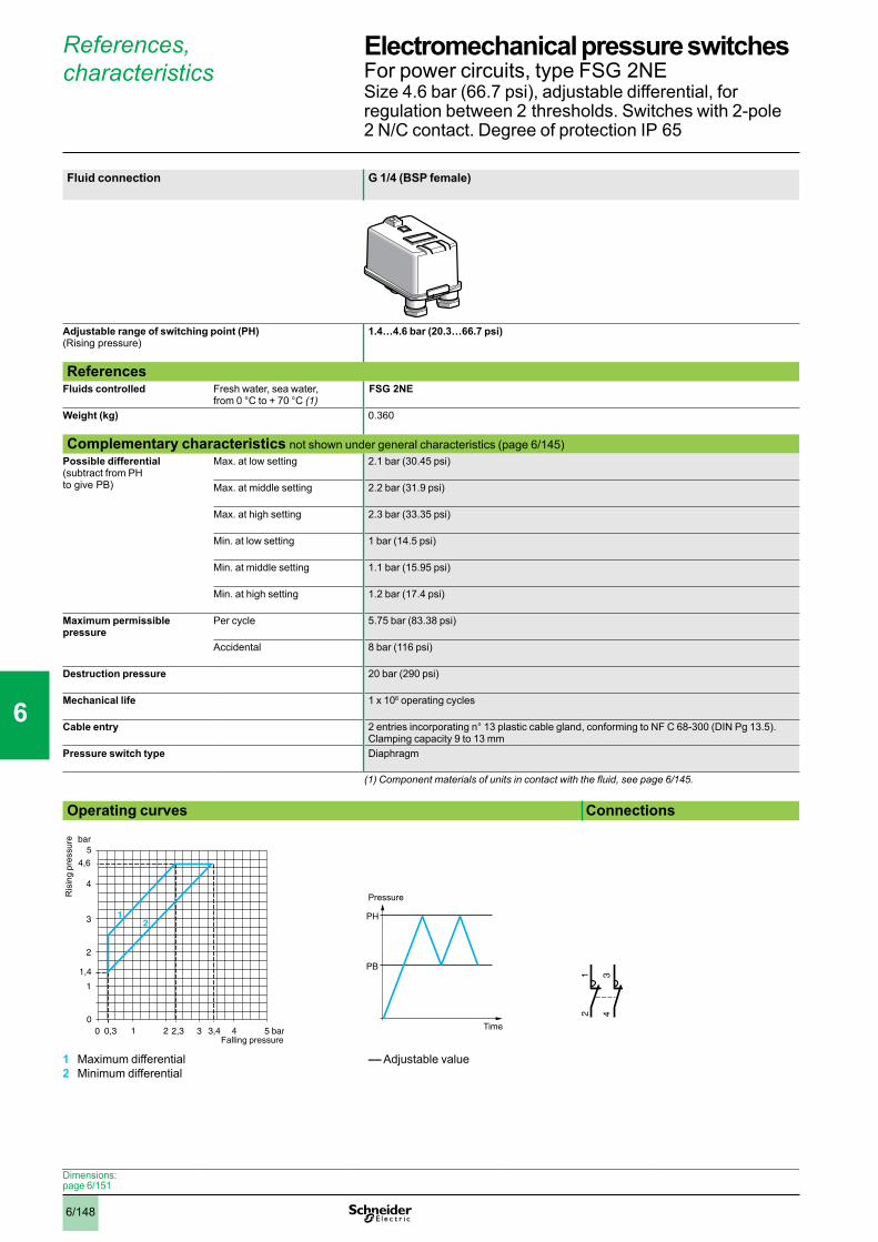
6/148
References, characteristics
Fluid connection G 1/4 (BSP female)
Adjustable range of switching point (PH) (Rising pressure)
1.4…4.6 bar (20.3…66.7 psi)
ReferencesFluids controlled Fresh water, sea water,
from 0 °C to + 70 °C (1) FSG 2NE
Weight (kg) 0.360
Complementary characteristics not shown under general characteristics (page 6/145)Possible differential (subtract from PH to give PB)
Max. at low setting 2.1 bar (30.45 psi)
Max. at middle setting 2.2 bar (31.9 psi)
Max. at high setting 2.3 bar (33.35 psi)
Min. at low setting 1 bar (14.5 psi)
Min. at middle setting 1.1 bar (15.95 psi)
Min. at high setting 1.2 bar (17.4 psi)
Maximum permissible pressure
Per cycle 5.75 bar (83.38 psi)
Accidental 8 bar (116 psi)
Destruction pressure 20 bar (290 psi)
Mechanical life 1 x 10⁶ operating cycles
Cable entry 2 entries incorporating n° 13 plastic cable gland, conforming to NF C 68-300 (DIN Pg 13.5). Clamping capacity 9 to 13 mm
Pressure switch type Diaphragm
(1)Componentmaterialsofunitsincontactwiththefluid,seepage6/145.
Operating curves Connections
1 Maximum differential2 Minimum differential
–– Adjustable value
bar
bar
0
4
3
2
1
5
3,4210 4 5
4,6
1,4
0,3 3
12
2,3Falling pressure
Ris
ing
pres
sure
PH
PB
Pressure
Time
34
12
Dimensions:page 6/151
Electromechanical pressure switches 0 For power circuits, type FSG 2NESize 4.6 bar (66.7 psi), adjustable differential, for regulation between 2 thresholds. Switches with 2-pole 2 N/C contact. Degree of protection IP 65
1
2
3
4
5
6
7
8
9
10

6/149
References, characteristics
Fluid connection G 1/4 (BSP female)
Adjustable range of switching point (PH) (Rising pressure)
2.8…7 bar (40.6…101.5 psi) 5.6…10.5 bar (81.2…152.3 psi)
ReferencesFluids controlled Fresh water, sea water,
from 0 °C to + 70 °C (1) FYG 22 FYG 32
Weight (kg) 0.340
Complementary characteristics not shown under general characteristics (page 6/145)Possible differential (subtract from PH to give PB)
Max. at low setting 2.3 bar (33.35 psi) 3 bar (43.5 psi)
Max. at middle setting 2.5 bar (36.25 psi) 3.2 bar (46.4 psi)
Max. at high setting 2.7 bar (39.15 psi) 3.4 bar (49.3 psi)
Min. at low setting 1.2 bar (17.4 psi) 1.9 bar (27.55 psi)
Min. at middle setting 1.4 bar (20.3 psi) 2.1 bar (30.45 psi)
Min. at high setting 1.6 bar (23.2 psi) 2.3 bar (33.35 psi)
Maximum permissible pressure
Per cycle 8.75 bar (126.9 psi) 13 bar (188.5 psi)
Accidental 15 bar (217.5 psi) 15 bar (217.5 psi)
Destruction pressure 20 bar (290 psi) 20 bar (290 psi)
Mechanical life 1 x 10⁶ operating cycles
Cable entry 2 cable entries, with grommet
Pressure switch type Diaphragm
(1)Componentmaterialsofunitsincontactwiththefluid,seepage6/145.
Operating curves ConnectionsFYG 22 FYG 32
1 Maximum differential2 Minimum differential
1 Maximum differential2 Minimum differential
–– Adjustable value
bar
bar
0
4
2,8
2
1
5
210 83
1 2
5,4 6 7
6
7
8
0,5 4,3Falling pressure
Ris
ing
pres
sure
bar
bar
0
4
3
2
1
5
2,610 4 5
10
1
2
6 7,1 8,2 9 10
5,6
7
8
9
Falling pressure
Ris
ing
pres
sure
PH
PB
Pressure
Time
34
12
Dimensions:page 6/151
Electromechanical pressure switches 0 For power circuits, type FYGSizes 7 and 10.5 bar (101.5 and 152.3 psi), adjustabledifferential, for regulation between 2 thresholds. Switcheswith 2-pole 2 N/C contact. Degree of protection IP 20
1
2
3
4
5
6
7
8
9
10
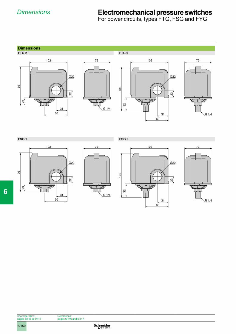
6/150
Dimensions
DimensionsFTG 2 FTG 9
FSG 2 FSG 9
72
96
23
22
102
Ø22
60
31 G 1/4
R 1/4
72
105
32
102
22
60
31
Ø22
72
96
23
22
102
Ø22
60
31 G 1/4
R 1/4
72
105
32
102
22
60
31
Ø22
Characteristics: pages 6/145 to 6/147
References:pages 6/146 and 6/147
Electromechanical pressure switches 0 For power circuits, types FTG, FSG and FYG
1
2
3
4
5
6
7
8
9
10
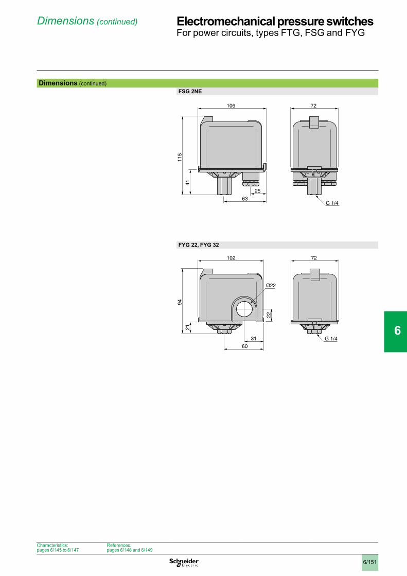
6/151
Dimensions(continued)
Dimensions (continued)FSG 2NE
FYG 22, FYG 32
115
41
106
25
72
63G 1/4
72
22
94
21
102
60
31
Ø22
G 1/4
Characteristics:pages 6/145 to 6/147
References:pages 6/148 and 6/149
Electromechanical pressure switches 0 For power circuits, types FTG, FSG and FYG
1
2
3
4
5
6
7
8
9
10
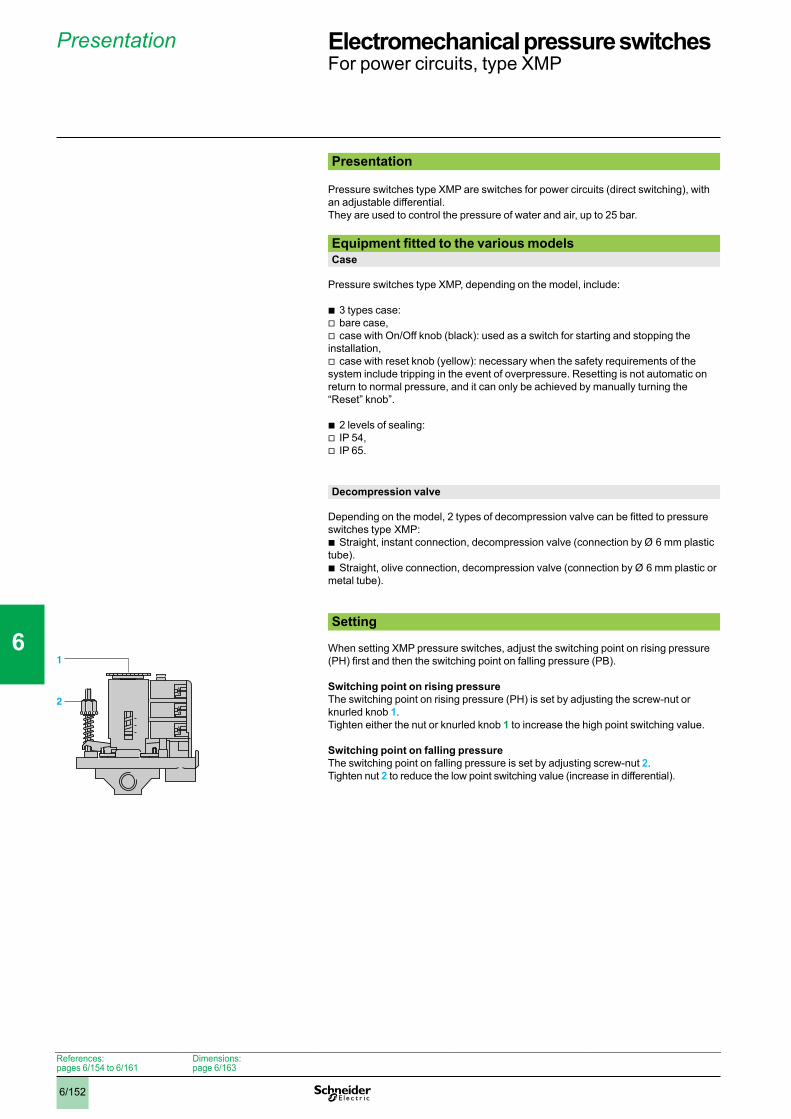
6/152
Presentation
Presentation
Pressure switches type XMP are switches for power circuits (direct switching), with an adjustable differential.They are used to control the pressure of water and air, up to 25 bar. Equipment fitted to the various modelsCase
Pressure switches type XMP, depending on the model, include:
3 types case:bare case, case with On/Off knob (black): used as a switch for starting and stopping the
installation, case with reset knob (yellow): necessary when the safety requirements of the
system include tripping in the event of overpressure. Resetting is not automatic on return to normal pressure, and it can only be achieved by manually turning the “Reset” knob”.
2 levels of sealing:IP 54, IP 65.
Decompression valve
Depending on the model, 2 types of decompression valve can be fitted to pressure switches type XMP:
Straight, instant connection, decompression valve (connection by Ø 6 mm plastic tube).
Straight, olive connection, decompression valve (connection by Ø 6 mm plastic or metal tube).
Setting
When setting XMP pressure switches, adjust the switching point on rising pressure (PH) first and then the switching point on falling pressure (PB).
Switching point on rising pressureThe switching point on rising pressure (PH) is set by adjusting the screw-nut or knurled knob 1.Tighten either the nut or knurled knob 1 to increase the high point switching value.
Switching point on falling pressureThe switching point on falling pressure is set by adjusting screw-nut 2.Tighten nut 2 to reduce the low point switching value (increase in differential).
bvv
v
bvv
b
b
1
2
References:pages 6/154 to 6/161
Dimensions:page 6/163
Electromechanical pressure switches 0 For power circuits, type XMP
1
2
3
4
5
6
7
8
9
10

6/153
Characteristics
Environmental characteristicsConformity to standards e, IEC/EN 60947-4-1
Ambient air temperature °C For operation: - 25…+ 70 For storage: - 40…+ 70
Fluids controlled Air, fresh water, sea water (0…+ 70 °C)
Materials Case: polyamide impregnated with fibreglass Component materials in contact with fluid: chromated zinc alloy (fluid entry), canvas covered nitrile (diaphragm)
Operating position All positions
Vibration resistance 3 gn (10…500 Hz), conforming to IEC 68-2-6
Shock resistance 50 gn, conforming to IEC 68-2-27
Electric shock protection Class I conforming to IEC 536
Degree of protection IP 54 conforming to IEC/EN 60529 or IP 65 for universal model
Operating rate Op.cycles/h
y 600
Repeat accuracy < 3.5%
Fluid connection G 1/4, 4 x G 1/4 or G 3/8 (BSP female) conforming to NF E 03-005, ISO 228
Electrical connection 2 tapped entries for n° 13 (DIN Pg 13.5) cable gland
Contact block characteristicsRated insulation voltage V Ui = 500 conforming to IEC/EN 60947-1
Rated impulse withstand voltage V U imp = 6 kV conforming to IEC/EN 60 947-1
Type of contacts One 2-pole 2 N/C or 3-pole 3 N/C contact, snap action
Resistance across terminals mW y 25 conforming to NF C 93-050 method A or IEC 255-7 category 3
Terminal referencing Conforming to CENELEC EN 50013
Short-circuit protection Cartridge fuse type Am
Connection Screw clamp terminals. Minimum clamping capacity: 2 x 4 mm2
Electrical durabilityOperating rate: 600 operating cycles/hourLoad factor: 0.4
Power Number of operating cycles
kW a 400 V, 3-phase a 230 V, 3-phase
1.5 1 000 000 600 000
2.2 700 000 –
3 500 000 –
References:pages 6/154 to 6/161
Dimensions:page 6/163
Electromechanical pressure switches 0 For power circuits, type XMP
1
2
3
4
5
6
7
8
9
10
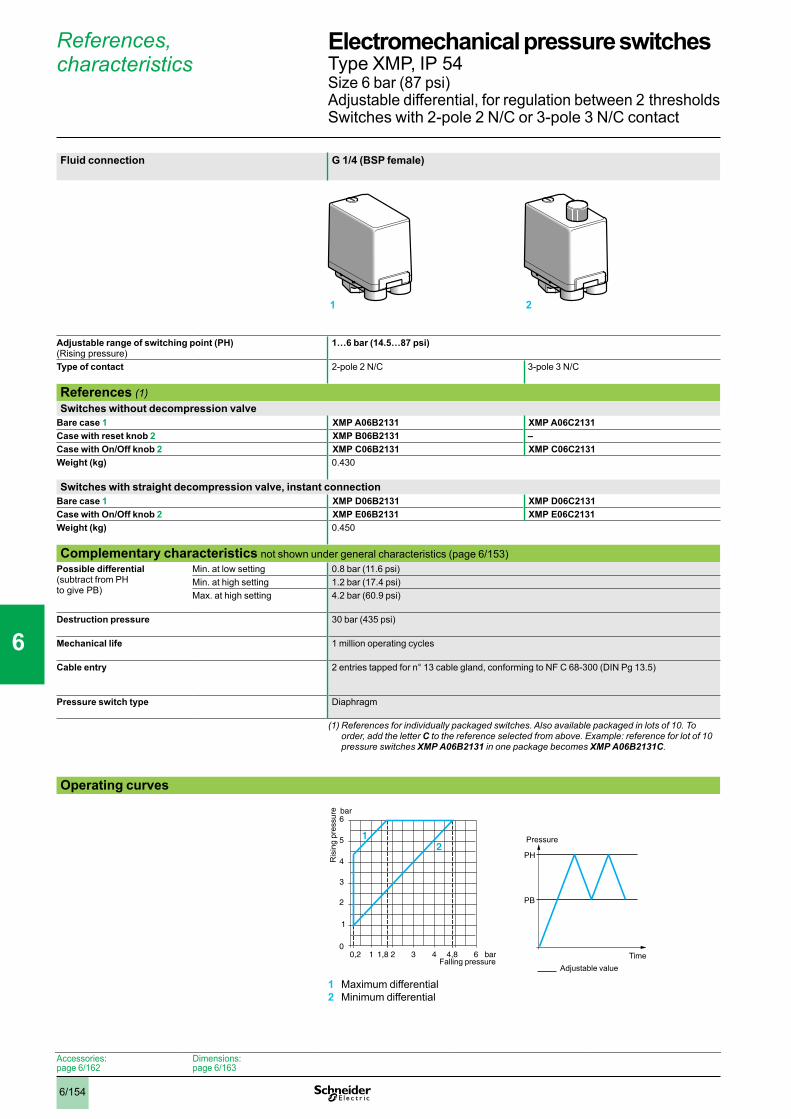
6/154
References, characteristics
Fluid connection G 1/4 (BSP female)
Adjustable range of switching point (PH) (Rising pressure)
1…6 bar (14.5…87 psi)
Type of contact 2-pole 2 N/C 3-pole 3 N/C
References (1)Switches without decompression valve
Bare case 1 XMP A06B2131 XMP A06C2131Case with reset knob 2 XMP B06B2131 –Case with On/Off knob 2 XMP C06B2131 XMP C06C2131Weight (kg) 0.430
Switches with straight decompression valve, instant connectionBare case 1 XMP D06B2131 XMP D06C2131Case with On/Off knob 2 XMP E06B2131 XMP E06C2131Weight (kg) 0.450
Complementary characteristics not shown under general characteristics (page 6/153)Possible differential (subtract from PH to give PB)
Min. at low setting 0.8 bar (11.6 psi)Min. at high setting 1.2 bar (17.4 psi)Max. at high setting 4.2 bar (60.9 psi)
Destruction pressure 30 bar (435 psi)
Mechanical life 1 million operating cycles
Cable entry 2 entries tapped for n° 13 cable gland, conforming to NF C 68-300 (DIN Pg 13.5)
Pressure switch type Diaphragm
(1)Referencesforindividuallypackagedswitches.Alsoavailablepackagedinlotsof10.Toorder, add the letter C to the reference selected from above. Example: reference for lot of 10 pressure switches XMP A06B2131 in one package becomes XMP A06B2131C.
Operating curves
1 Maximum differential2 Minimum differential
1 2
1 2 3
3
0
4
5
6
1
2
4 60,2 1,8 4,8
21
bar
bar
Falling pressure
Ris
ing
pres
sure
PH
PB
Pressure
Time
Adjustable value
Accessories:page 6/162
Dimensions:page 6/163
Electromechanical pressure switches 0 Type XMP, IP 54Size 6 bar (87 psi) Adjustable differential, for regulation between 2 thresholdsSwitches with 2-pole 2 N/C or 3-pole 3 N/C contact
1
2
3
4
5
6
7
8
9
10

6/155
4 x G 1/4 (BSP female) G 3/8 (BSP female)
1…6 bar (14.5…87 psi)
2-pole 2 N/C 3-pole 3 N/C 2-pole 2 N/C 3-pole 3 N/C
References (1)Switches without decompression valve
– XMP A06B2242 XMP A06C2242– XMP B06B2242 –– XMP C06B2242 XMP C06C2242– 0.430
Switches with straight decompression valve, instant connection– XMP D06B2242 XMP D06C2242XMP E06B2431 XMP E06C2431 XMP E06B2242 XMP E06C22420.450
Complementary characteristics not shown under general characteristics (page 6/153)0.8 bar (11.6 psi)1.2 bar (17.4 psi)4.2 bar (60.9 psi)
30 bar (435 psi)
1 million operating cycles
2 entries tapped for n° 13 cable gland, conforming to NF C 68-300 (DIN Pg 13.5)
2 entries incorporating n° 13 plastic cable gland (DIN Pg 13.5) Clamping capacity 9 to 13 mm
Diaphragm
Other versions Pressure switches not listed above, comprising the equipment proposed for the choice of reference. Please consult your Regional Sales Office.(1)Referencesforindividuallypackagedswitches.Alsoavailablepackagedinlotsof10.To
order, add the letter C to the reference selected from above. Example: reference for lot of 10 pressure switches XMP A06B2242 in one package becomes XMP A06B2242C.
Terminal connectionsXMP pppBpppp XMP pppCpppp
21 2
34
12
56
34
12
Accessories:page 6/162
Dimensions:page 6/163
0
1
2
3
4
5
6
7
8
9
10

6/156
Adjustable value
References, characteristics (continued)
Fluid connection G 1/4 (BSP female)
Adjustable range of switching point (PH) (Rising pressure)
1.3…12 bar (18.85…174 psi)
Type of contact 2-pole 2 N/C 3-pole 3 N/C
References (1)Switches without decompression valve
Bare case 1 XMP A12B2131 XMP A12C2131Case with reset knob 2 XMP B12B2131 –Case with On/Off knob 2 XMP C12B2131 XMP C12C2131Weight (kg) 0.430
Switches with straight decompression valve, instant connectionBare case 1 XMP D12B2131 XMP D12C2131Case with On/Off knob 2 XMP E12B2131 XMP E12C2131Weight (kg) 0.450
Switches with straight decompression valve, olive connectionCase with On/Off knob 2 XMP R12B2131 XMP R12C2131Weight (kg) 0.450
Complementary characteristics not shown under general characteristics (page 6/153)Possible differential (subtract from PH to give PB)
Min. at low setting 1 bar (14.5 psi)Min. at high setting 1.7 bar (24.6 psi)Max. at high setting 8.4 bar (121.8 psi)
Destruction pressure 30 bar (435 psi)
Mechanical life 1 million operating cycles
Cable entry 2 entries tapped for n° 13 cable gland, conforming to NF C 68-300 (DIN Pg 13.5)
Pressure switch type Diaphragm
(1)Referencesforindividuallypackagedswitches.Alsoavailablepackagedinlotsof10.Toorder, add the letter C to the reference selected from above. Example: reference for lot of 10 pressure switches XMP A12B2131 in one package becomes XMP A12B2131C.
Operating curves
1 Maximum differential2 Minimum differential
1 2
bar2 4 6
6
0
8
10
12
2
4
8 100,3 3,6 10,3
2
1
1,3
bar
Falling pressure
Ris
ing
pres
sure
PH
PB
Pressure
Time
Accessories:page 6/162
Dimensions:page 6/163
Electromechanical pressure switches 0 Type XMP, IP 54Size 12 bar (174 psi) Adjustable differential, for regulation between 2 thresholdsSwitches with 2-pole 2 N/C or 3-pole 3 N/C contact
1
2
3
4
5
6
7
8
9
10

6/157
4 x G 1/4 (BSP female) G 3/8 (BSP female)
1.3…12 bar (18.85…174 psi)
2-pole 2 N/C 3-pole 3 N/C 2-pole 2 N/C 3-pole 3 N/C
References (1)Switches without decompression valve
– XMP A12B2242 XMP A12C2242– XMP B12B2242 –– XMP C12B2242 XMP C12C2242– 0.430
Switches with straight decompression valve, instant connection– XMP D12B2242 XMP D12C2242XMP E12B2431 XMP E12C2431 XMP E12B2242 XMP E12C22420.450
Switches with straight decompression valve, olive connection––
Complementary characteristics not shown under general characteristics (page 6/153)1 bar (14.5 psi)1.7 bar (24.6 psi)8.4 bar (121.8 psi)
30 bar (435 psi)
1 million operating cycles
2 entries tapped for n° 13 cable gland, conforming to NF C 68-300 (DIN Pg 13.5)
2 entries incorporating n° 13 plastic cable gland (DIN Pg 13.5) Clamping capacity 9 to 13 mm
Diaphragm
Other versions Pressure switches not listed above, comprising the equipment proposed for the choice of reference. Please consult your Regional Sales Office.(1)Referencesforindividuallypackagedswitches.Alsoavailablepackagedinlotsof10.To
order, add the letter C to the reference selected from above. Example: reference for lot of 10 pressure switches XMP A12B2242 in one package becomes XMP A12B2242C.
Terminal connectionsXMP pppBpppp XMP pppCpppp
2 1 2
34
12
56
34
12
Accessories:page 6/162
Dimensions:page 6/163
0
1
2
3
4
5
6
7
8
9
10
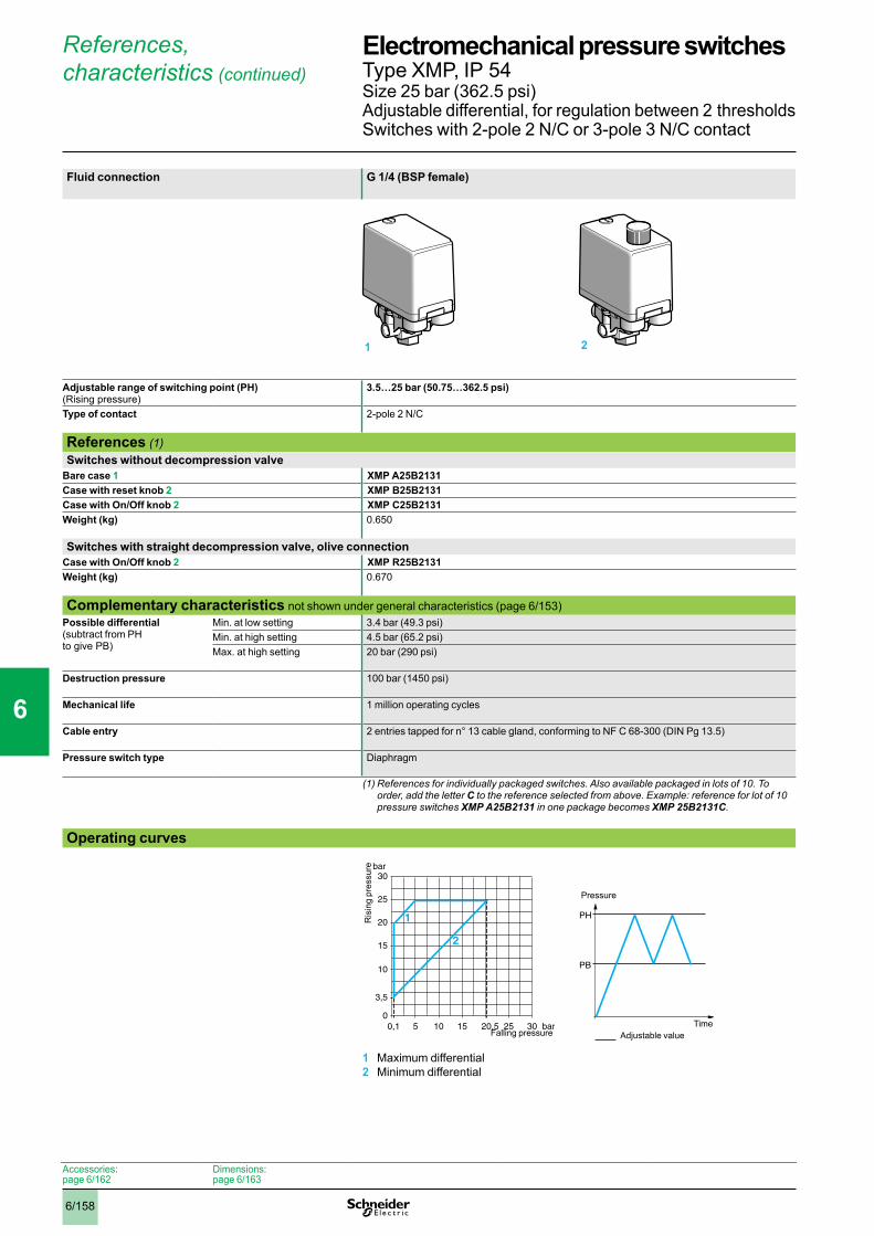
6/158
References, characteristics (continued)
Fluid connection G 1/4 (BSP female)
Adjustable range of switching point (PH) (Rising pressure)
3.5…25 bar (50.75…362.5 psi)
Type of contact 2-pole 2 N/C
References (1)Switches without decompression valve
Bare case 1 XMP A25B2131Case with reset knob 2 XMP B25B2131Case with On/Off knob 2 XMP C25B2131Weight (kg) 0.650
Switches with straight decompression valve, olive connectionCase with On/Off knob 2 XMP R25B2131Weight (kg) 0.670
Complementary characteristics not shown under general characteristics (page 6/153)Possible differential (subtract from PH to give PB)
Min. at low setting 3.4 bar (49.3 psi)Min. at high setting 4.5 bar (65.2 psi)Max. at high setting 20 bar (290 psi)
Destruction pressure 100 bar (1450 psi)
Mechanical life 1 million operating cycles
Cable entry 2 entries tapped for n° 13 cable gland, conforming to NF C 68-300 (DIN Pg 13.5)
Pressure switch type Diaphragm
(1)Referencesforindividuallypackagedswitches.Alsoavailablepackagedinlotsof10.Toorder, add the letter C to the reference selected from above. Example: reference for lot of 10 pressure switches XMP A25B2131 in one package becomes XMP 25B2131C.
Operating curves
1 Maximum differential2 Minimum differential
1 2
5 10 15
15
0
20
25
30
10
25 300,1 20,5
1
3,5
bar
bar
2
Falling pressure
Ris
ing
pres
sure
PH
PB
Pressure
Time Adjustable value
Accessories:page 6/162
Dimensions:page 6/163
Electromechanical pressure switches 0 Type XMP, IP 54Size 25 bar (362.5 psi) Adjustable differential, for regulation between 2 thresholdsSwitches with 2-pole 2 N/C or 3-pole 3 N/C contact
1
2
3
4
5
6
7
8
9
10
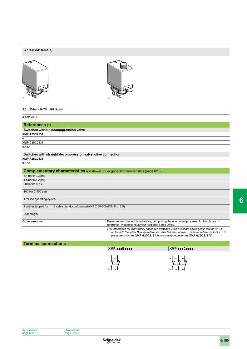
6/159
G 1/4 (BSP female)
3.5…25 bar (50.75…362.5 psi)
3-pole 3 N/C
References (1)Switches without decompression valve
XMP A25C2131–XMP C25C21310.650
Switches with straight decompression valve, olive connectionXMP R25C21310.670
Complementary characteristics not shown under general characteristics (page 6/153)3.4 bar (49.3 psi)4.5 bar (65.2 psi)20 bar (290 psi)
100 bar (1450 psi)
1 million operating cycles
2 entries tapped for n° 13 cable gland, conforming to NF C 68-300 (DIN Pg 13.5)
Diaphragm
Other versions Pressure switches not listed above, comprising the equipment proposed for the choice of reference. Please consult your Regional Sales Office.(1)Referencesforindividuallypackagedswitches.Alsoavailablepackagedinlotsof10.To
order, add the letter C to the reference selected from above. Example: reference for lot of 10 pressure switches XMP A25C2131 in one package becomes XMP A25C2131C.
Terminal connectionsXMP pppBpppp XMP pppCpppp
1 2
34
12
56
34
12
Accessories:page 6/162
Dimensions:page 6/163
0
1
2
3
4
5
6
7
8
9
10
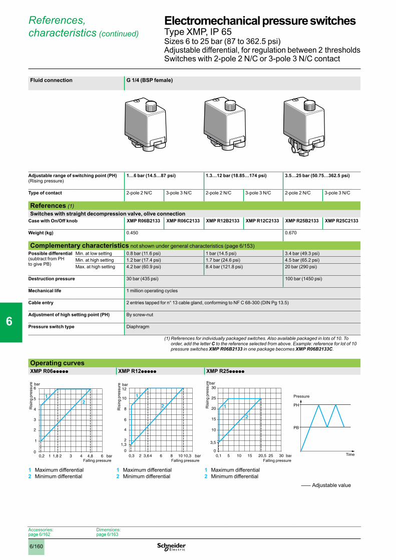
6/160
Adjustable value
References, characteristics (continued)
Fluid connection G 1/4 (BSP female)
Adjustable range of switching point (PH) (Rising pressure)
1…6 bar (14.5…87 psi) 1.3…12 bar (18.85…174 psi) 3.5…25 bar (50.75…362.5 psi)
Type of contact 2-pole 2 N/C 3-pole 3 N/C 2-pole 2 N/C 3-pole 3 N/C 2-pole 2 N/C 3-pole 3 N/C
References (1)Switches with straight decompression valve, olive connection
Case with On/Off knob XMP R06B2133 XMP R06C2133 XMP R12B2133 XMP R12C2133 XMP R25B2133 XMP R25C2133
Weight (kg) 0.450 0.670
Complementary characteristics not shown under general characteristics (page 6/153)Possible differential (subtract from PH to give PB)
Min. at low setting 0.8 bar (11.6 psi) 1 bar (14.5 psi) 3.4 bar (49.3 psi)Min. at high setting 1.2 bar (17.4 psi) 1.7 bar (24.6 psi) 4.5 bar (65.2 psi)Max. at high setting 4.2 bar (60.9 psi) 8.4 bar (121.8 psi) 20 bar (290 psi)
Destruction pressure 30 bar (435 psi) 100 bar (1450 psi)
Mechanical life 1 million operating cycles
Cable entry 2 entries tapped for n° 13 cable gland, conforming to NF C 68-300 (DIN Pg 13.5)
Adjustment of high setting point (PH) By screw-nut
Pressure switch type Diaphragm
(1)Referencesforindividuallypackagedswitches.Alsoavailablepackagedinlotsof10.Toorder, add the letter C to the reference selected from above. Example: reference for lot of 10 pressure switches XMP R06B2133 in one package becomes XMP R06B2133C.
Operating curvesXMP R06ppppp XMP R12ppppp XMP R25ppppp
1 Maximum differential2 Minimum differential
1 Maximum differential2 Minimum differential
1 Maximum differential2 Minimum differential
1 2 3
3
0
4
5
6
1
2
4 60,2 1,8 4,8
21
bar
bar
Falling pressure
Ris
ing
pres
sure
bar2 4 6
6
0
8
10
12
2
4
8 100,3 3,6 10,3
2
1
1,3
bar
Falling pressure
Ris
ing
pres
sure
5 10 15
15
0
20
25
30
10
25 300,1 20,5
1
3,5
bar
bar
2
Falling pressure
Ris
ing
pres
sure
PH
PB
Pressure
Time
Accessories:page 6/162
Dimensions:page 6/163
Electromechanical pressure switches 0 Type XMP, IP 65Sizes 6 to 25 bar (87 to 362.5 psi) Adjustable differential, for regulation between 2 thresholdsSwitches with 2-pole 2 N/C or 3-pole 3 N/C contact
1
2
3
4
5
6
7
8
9
10
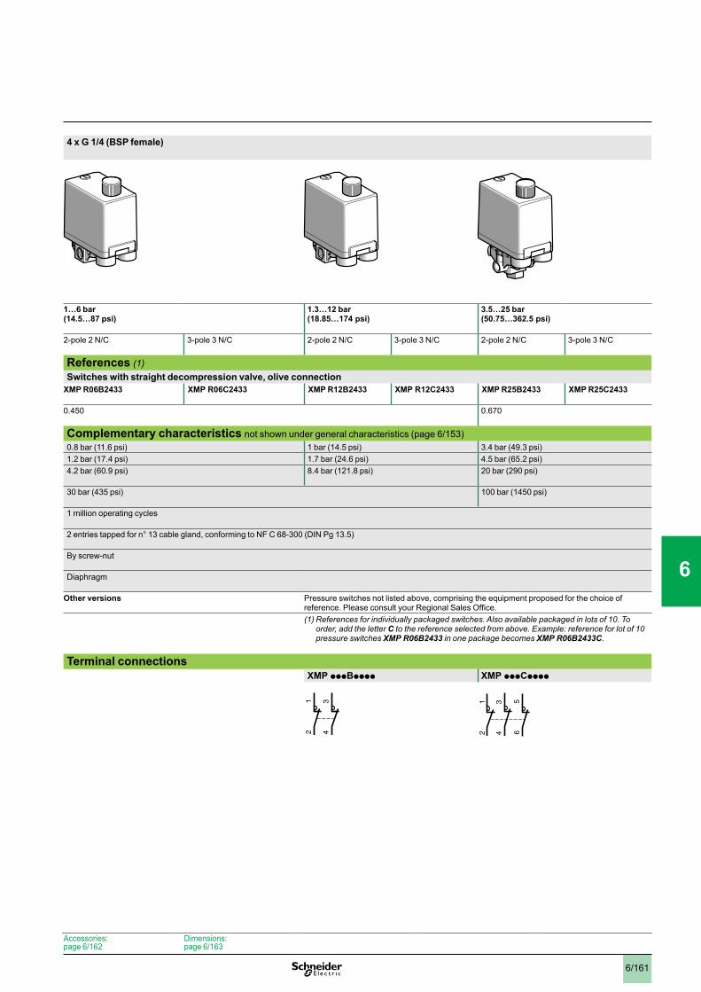
6/161
4 x G 1/4 (BSP female)
1…6 bar (14.5…87 psi)
1.3…12 bar (18.85…174 psi)
3.5…25 bar (50.75…362.5 psi)
2-pole 2 N/C 3-pole 3 N/C 2-pole 2 N/C 3-pole 3 N/C 2-pole 2 N/C 3-pole 3 N/C
References (1)Switches with straight decompression valve, olive connection
XMP R06B2433 XMP R06C2433 XMP R12B2433 XMP R12C2433 XMP R25B2433 XMP R25C2433
0.450 0.670
Complementary characteristics not shown under general characteristics (page 6/153)0.8 bar (11.6 psi) 1 bar (14.5 psi) 3.4 bar (49.3 psi)1.2 bar (17.4 psi) 1.7 bar (24.6 psi) 4.5 bar (65.2 psi)4.2 bar (60.9 psi) 8.4 bar (121.8 psi) 20 bar (290 psi)
30 bar (435 psi) 100 bar (1450 psi)
1 million operating cycles
2 entries tapped for n° 13 cable gland, conforming to NF C 68-300 (DIN Pg 13.5)
By screw-nut
Diaphragm
Other versions Pressure switches not listed above, comprising the equipment proposed for the choice of reference. Please consult your Regional Sales Office.(1)Referencesforindividuallypackagedswitches.Alsoavailablepackagedinlotsof10.To
order, add the letter C to the reference selected from above. Example: reference for lot of 10 pressure switches XMP R06B2433 in one package becomes XMP R06B2433C.
Terminal connectionsXMP pppBpppp XMP pppCpppp
34
12
56
34
12
Accessories:page 6/162
Dimensions:page 6/163
0
1
2
3
4
5
6
7
8
9
10
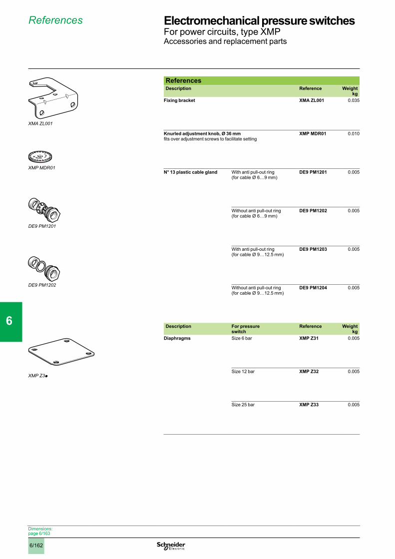
6/162
XMP Z3p
References
ReferencesDescription Reference Weight
kgFixing bracket XMA ZL001 0.035
Knurled adjustment knob, Ø 36 mm fits over adjustment screws to facilitate setting
XMP MDR01 0.010
N° 13 plastic cable gland With anti pull-out ring (for cable Ø 6…9 mm)
DE9 PM1201 0.005
Without anti pull-out ring (for cable Ø 6…9 mm)
DE9 PM1202 0.005
With anti pull-out ring (for cable Ø 9…12.5 mm)
DE9 PM1203 0.005
Without anti pull-out ring (for cable Ø 9…12.5 mm)
DE9 PM1204 0.005
Description For pressure switch
Reference Weight kg
Diaphragms Size 6 bar XMP Z31 0.005
Size 12 bar XMP Z32 0.005
Size 25 bar XMP Z33 0.005
XMA ZL001
XMPMDR01
DE9PM1201
DE9PM1202
Dimensions:page 6/163
Electromechanical pressure switches 0 For power circuits, type XMPAccessories and replacement parts
1
2
3
4
5
6
7
8
9
10

6/163
Dimensions
DimensionsXMP p06ppppp and XMP p12pppppFluid connection G 1/4 or G 3/8 (BSP female)Without decompression valve
Fluid connection 4 x G 1/4 (BSP female)Without decompression valve
With straight, instant conn- ection, decompression valve
With straight, olive conn-ection, decompression valve
ØA = G 1/4 or G 3/8 (BSP female) ØA = ØB = ØC = ØD = G 1/4 (BSP female)(1) 2 tapped entries for n° 13 cable gland(2) Minimum clearance zone for screwing-on pressure switch at point AXMP p25ppppp Fixing bracket XMA ZL001Fluid connection G 1/4 or 4 x G 1/4 (BSP female)Without decompression valve
With straight, olive connection, decompression valve
XMP p25p21pp: ØA only = G 1/4 (BSP female)XMP p25p24pp: ØA = ØB = ØC = ØD = G 1/4 (BSP female)(1) 2 tapped entries for n° 13 cable gland(2) Minimum clearance zone for screwing-on pressure switch at
point A
43,5
58
97,5
(1)
1910
6
30,5
=
57
=
A
r = 63 (2)
43,5
58
97,5
(1)
1910
6
30,5
=
57
=
r = 63 (2)
C
D
B
A
119
22,5
13
119
22,5
13
43,5
58
97,5
(1)
1912
6
30,5
=
57
=
AC
D
B
r = 63 (2)
22,5
136
18,512,5 38
3,6
54
40 19
24,7
5 52
Electromechanical pressure switches 0 For power circuits, type XMP
1
2
3
4
5
6
7
8
9
10
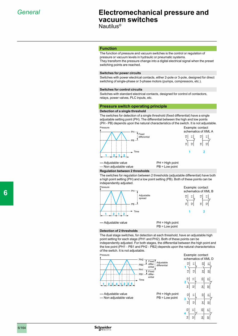
6/164
General
FunctionThe function of pressure and vacuum switches is the control or regulation of pressure or vacuum levels in hydraulic or pneumatic systems.They transform the pressure change into a digital electrical signal when the preset switching points are reached.
Switches for power circuitsSwitches with power electrical contacts, either 2-pole or 3-pole, designed for direct switching of single-phase or 3-phase motors (pumps, compressors, etc.).
Switches for control circuitsSwitches with standard electrical contacts, designed for control of contactors, relays, power valves, PLC inputs, etc.
Pressure switch operating principleDetection of a single thresholdThe switches for detection of a single threshold (fixed differential) have a single adjustable setting point (PH). The differential between the high and low points (PH - PB) depends upon the natural characteristics of the switch. It is not adjustable.
Example: contact schematics of XML A
1 2
–– Adjustable value--- Non adjustable value
PH = High pointPB = Low point
Regulation between 2 thresholdsThe switches for regulation between 2 thresholds (adjustable differential) have both a high point setting (PH) and a low point setting (PB). Both of these points can be independently adjusted.
Example: contact schematics of XML B
1 2
–– Adjustable value PH = High pointPB = Low point
Detection of 2 thresholdsThe dual stage switches, for detection at each threshold, have an adjustable high point setting for each stage (PH1 and PH2). Both of these points can be independently adjusted. For both stages, the differential between the high point and the low point (PH1 - PB1 and PH2 - PB2) depends upon the natural characteristics of the switch. It is not adjustable.
Example: contact schematics of XML D
–– Adjustable value--- Non adjustable value
PH = High pointPB = Low point
1 2 1 2
Pressure
Fixed differential
Time
PB
PH
1314 12
11 1314 12
11
1 2 1 2
Pressure
Adjustable spread
Time
PH
PB
1314 12
11 1314 12
11
PH2
PH1
PB1
PB2
1 2 43 1 2 43
Pressure
Fixed differ-ential
Fixed differ-ential
Time
Adjustable differential 2
324
22
21
13
14
12
11
1
23
24
22
21
13
14
12
11
2
23
24
22
21
13
14
12
11
3
23
24
22
2113
14
12
11
4
Electromechanical pressure and vacuum switches 0 Nautilus®
1
2
3
4
5
6
7
8
9
10

6/165
General(continued)
Vacuum switch operating principleDetection of a single thresholdThe switches for detection of a single threshold (fixed differential) have a single adjustable setting point (PH).The differential between the high and low points (PH - PB) depends upon the natural characteristics of the switch. It is not adjustable.
Example: contact schematics of XML A
1 2
–– Adjustable value--- Non adjustable value
PH = High pointPB = Low point
Regulation between 2 thresholdsThe switches for regulation between 2 thresholds (adjustable differential) have both a high point setting (PH) and a low point setting (PB). Both of these points can be independently adjusted.
Example: contact schematics of XML B
1 2
–– Adjustable value
PH = High pointPB = Low point
Detection of 2 thresholdsThe dual stage switches, for detection at each threshold, have an adjustable high point setting for each stage (PH1 and PH2). Both of these points can be independently adjusted.For both stages, the differential between the high point and the low point (PH1 - PB1 and PH2 - PB2) depends upon the natural characteristics of the switch. It is not adjustable.
Example: contact schematics of XML D
–– Adjustable value--- Non adjustable value
PH = High pointPB = Low point
1 2 1 2
Vacuum
Fixed differential
Time
PB
PH
1314 12
11 1314 12
11
1 2 1 2
Vacuum
Adjustable spread
Time
PB
PH
1314 12
11 1314 12
11
PH1
PH2
PB2
PB1
1 2 43 1 2 43
Fixed differ-ential
Fixed differ-ential
Time
Adjustable differential
Vacuum
23
24
22
21
13
14
12
11
1
13
14
12
11
23
24
22
21
2
23
24
22
2113
14
12
11
3
13
14
12
11
23
24
22
21
4
Electromechanical pressure and vacuum switches 0 Nautilus®
1
2
3
4
5
6
7
8
9
10
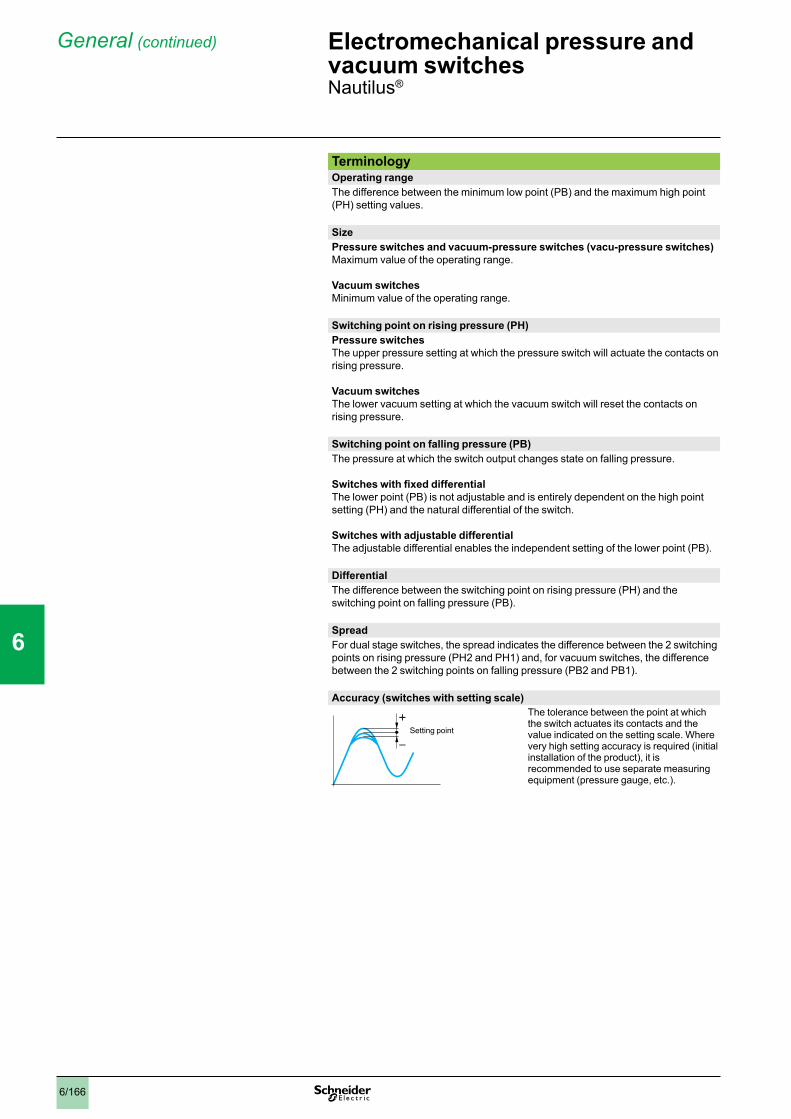
6/166
General(continued)
TerminologyOperating rangeThe difference between the minimum low point (PB) and the maximum high point (PH) setting values.
SizePressure switches and vacuum-pressure switches (vacu-pressure switches)Maximum value of the operating range.
Vacuum switchesMinimum value of the operating range.
Switching point on rising pressure (PH)Pressure switchesThe upper pressure setting at which the pressure switch will actuate the contacts on rising pressure. Vacuum switchesThe lower vacuum setting at which the vacuum switch will reset the contacts on rising pressure.
Switching point on falling pressure (PB)The pressure at which the switch output changes state on falling pressure.
Switches with fixed differentialThe lower point (PB) is not adjustable and is entirely dependent on the high point setting (PH) and the natural differential of the switch.
Switches with adjustable differentialThe adjustable differential enables the independent setting of the lower point (PB).
DifferentialThe difference between the switching point on rising pressure (PH) and the switching point on falling pressure (PB).
SpreadFor dual stage switches, the spread indicates the difference between the 2 switching points on rising pressure (PH2 and PH1) and, for vacuum switches, the difference between the 2 switching points on falling pressure (PB2 and PB1).
Accuracy (switches with setting scale)The tolerance between the point at which the switch actuates its contacts and the value indicated on the setting scale. Where very high setting accuracy is required (initial installation of the product), it is recommended to use separate measuring equipment (pressure gauge, etc.).
+
–Setting point
Electromechanical pressure and vacuum switches 0 Nautilus®
1
2
3
4
5
6
7
8
9
10
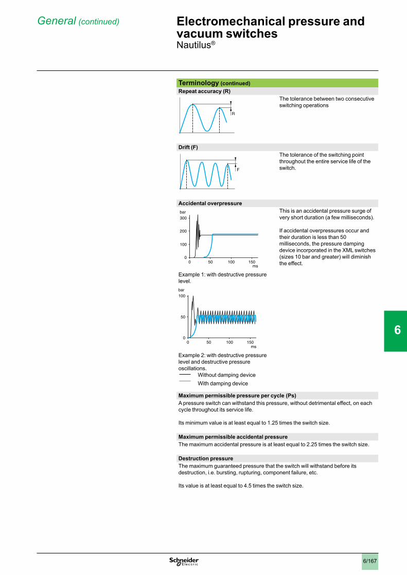
6/167
General(continued)
Terminology (continued)Repeat accuracy (R)
The tolerance between two consecutive switching operations
Drift (F)The tolerance of the switching point throughout the entire service life of the switch.
Accidental overpressureThis is an accidental pressure surge of very short duration (a few milliseconds).
If accidental overpressures occur and their duration is less than 50 milliseconds, the pressure damping device incorporated in the XML switches (sizes 10 bar and greater) will diminish the effect.
Example 1: with destructive pressure level.
Example 2: with destructive pressure level and destructive pressure oscillations.
Without damping deviceWith damping device
Maximum permissible pressure per cycle (Ps)A pressure switch can withstand this pressure, without detrimental effect, on each cycle throughout its service life.
Its minimum value is at least equal to 1.25 times the switch size.
Maximum permissible accidental pressureThe maximum accidental pressure is at least equal to 2.25 times the switch size.
Destruction pressureThe maximum guaranteed pressure that the switch will withstand before its destruction, i.e. bursting, rupturing, component failure, etc.
Its value is at least equal to 4.5 times the switch size.
R
F
300bar
200
100
00 50 100 150
ms
0 50 100 1500
50
100bar
ms
Electromechanical pressure and vacuum switches 0 Nautilus®
1
2
3
4
5
6
7
8
9
10
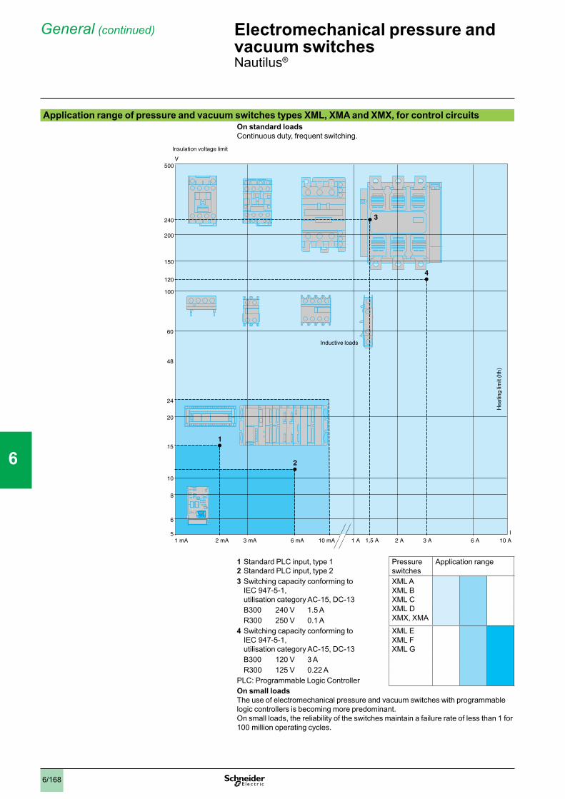
6/168
General(continued)
Application range of pressure and vacuum switches types XML, XMA and XMX, for control circuitsOn standard loadsContinuous duty, frequent switching.
1 Standard PLC input, type 12 Standard PLC input, type 2
Pressure switches
Application range
3 Switching capacity conforming to IEC 947-5-1, utilisation category AC-15, DC-13
XML A XML B XML C XML D XMX, XMA
B300 240 V 1.5 A R300 250 V 0.1 A4 Switching capacity conforming to
IEC 947-5-1, utilisation category AC-15, DC-13
XML E XML F XML G
B300 120 V 3 A R300 125 V 0.22 APLC: Programmable Logic ControllerOn small loadsThe use of electromechanical pressure and vacuum switches with programmable logic controllers is becoming more predominant.On small loads, the reliability of the switches maintain a failure rate of less than 1 for 100 million operating cycles.
5
6
10
8
20
60
100
15
150
200
500
120
240
24
V
48
1 mA 2 mA 3 mA 6 mA 10 mA 2 A 3 A 6 A 10 A 1 A
1
2
3
4
I1,5 A
Insulation voltage limit
Inductive loads
Hea
ting
limit
(lth)
Electromechanical pressure and vacuum switches 0 Nautilus®
1
2
3
4
5
6
7
8
9
10

6/169
Selection of switch sizeAfter establishing the type of switch required for the application (single threshold detection or regulation between 2 thresholds), the selection of its size will depend on the following criteria:
the differential: difference between the high point (PH) and the low point (PB),the maximum pressure permissible per cycle,repeat accuracy, precision and minimum drift.
vvv
Examples of a fixed differential pressure switch selection, for detection of a single threshold Main criterion: minimum differential Example: for a selected high point (PH) of 7 bar
XML A010pppppDifferential = 0.5 bar
XML A020pppppDifferential = 1 bar
XML A035pppppDifferential = 2 bar
Select an XML A010ppppp (the lowest size)
Main criterion: tolerance to overpressures Example: for a selected high point (PH) of 12 bar
XML A020pppppPermissible accidental overpressure = 45 bar
XML A035pppppPermissible accidental overpressure = 80 bar
Select an XML A035ppppp (the highest size)
Main criterion: repeat accuracy, precision and minimum driftExample: for a selected high point (PH) of 18 bar
As a general rule, working at the upper or lower limits of the operating range should be avoided.
XML A020pppppAdjustable from 1 to 20 bar
XML A035pppppAdjustable from 1.5 to 35 bar
Select an XML A035ppppp
Units of pressure conversion tablepsi kg/cm2 bar atm mm Hg
(Torr)mm H2O Pa
1 psi = 1 0.07031 0.06895 0.06805 51.71 703.7 68951 kg/cm2 = 14.22 1 0.98066 0.96784 735.55 10 000 98 0661 bar = 14.50 1.0197 1 0.98695 750.06 10 197 105
1 atm = 14.70 1.0333 1.0132 1 760.0 10 333 101 3251 mm Hg = (Torr)
0.01934 1.360 x 10⁻³
1.333 x 10⁻³
1.316 x 10⁻³
1 13.59 133.3
1 mm H2O = 1.421 x 10⁻³
10-4 a 10-4 a 10-4 0.07361 1 a 9.80
1 Pa = 1.45 x 10⁻⁴ 1.0197 x 10⁻⁵
10-5 9.8695 x 10⁻⁶
7.5 x 10⁻³ 0.10197 1
Example: 1 bar = 14.50 psi = 105 Pa
10 bar
0,6
7 6,5
20 bar
1
7 6
35 bar
1,5
75
45 bar
1
12
2025
80 bar
1,5
12
35
45
20 bar
1
1835 bar
1,5
18
Electromechanical pressure and vacuum switches 0 Nautilus®
General(continued)
1
2
3
4
5
6
7
8
9
10

6/170
Operating curves
Adjustment range of the high point
Defined by the difference between the minimum and maximum high point (PH) setting values.
For a high set point (PH), the lower point (PB) is fixed and cannot be adjusted.For a low set point (PB), the higher point (PH) is fixed and cannot be adjusted.
Switching point on rising pressure (PH)
The upper pressure setting at which the pressure or vacuum switch will actuate the contacts on rising pressure.
Adjustable throughout the range on rising pressure.
Switching point on falling pressure (PB)
The pressure at which the switch contact changes state on falling pressure.
The lower point (PB) is not adjustable and is entirely dependent on the high point setting (PH) and the natural differential of the switch.
DifferentialPH - PB = natural differentialThe difference between the switching point on rising pressure (PH) and the switching point on falling pressure (PB).
This point is not adjustable and therefore, the value of the differential is fixed. It is the natural differential of the switch (contact differential, friction, etc.).
Example Consider a switching point on rising
pressure (PH) of 40 bar (set value at which the contact will change state on rising pressure).
It can be seen that the switching point on falling pressure (PB) is 28 bar (fixed value at which the contact will return to its original state).Conclusion:
the differential will be 40 - 28 = 12 bar.
b
b
v
Maxi+
–
Mini
00
Rising pressure
Falling pressure
Adj
ustm
ent r
ange
of
hig
h po
int (
PH
)Low point (PB) range
0
PH
+
– 0
Rising pressure
Falling pressure
0
PH
+
–
PB
PB0
Rising pressure
Falling pressure
PH
+
–
PB
PB
PH – PB
00
Rising pressure
Falling pressure
0 28PB
40 60203
20
PH 40
60
0
Rising pressure
Falling pressure
bar
bar
Electromechanical pressure and vacuum switches 0 Fixed differential switches, for detection of a single threshold
1
2
3
4
5
6
7
8
9
10

6/171
Operating curves
Adjustment range of the high point
Defined by the difference between the minimum and maximum high point (PH) setting values.
Switching point on rising pressure (PH)
The upper pressure setting at which the pressure or vacuum switch will actuate the contacts on rising pressure.
Adjustable throughout the range on rising pressure.
Switching point on falling pressure (PB)
The pressure at which the switch contact changes state on falling pressure.
The adjustable differential enables the independent setting of the lower point (PB).
DifferentialLow point < High pointPH - PB’ = natural differentialPH - PB” = minimum differential
The difference between the switching point on rising pressure (PH) and the switching point on falling pressure (PB).
Note: the low point can be set at any value between PB’ and PB”.
Example Consider a switching point on rising
pressure (PH) of 22 bar (set value at which the contact will change state on rising pressure).
It can be seen that the switching point on falling pressure (PB) can be between 4 and 19 bar inclusive (set value at which the contact will return to its original state).Conclusion:
the maximum differential will be 22 - 4 = 18 bar,
the minimum differential will be 22 - 19 = 3 bar.
b
b
v
v
Maxi
+
–
Mini
00
1 2
Falling pressure
Rising pressure
Low point (PB) range
Adj
ustm
ent r
ange
of
hig
h po
int (
PH
)
+
–0
0
1 2PH
Rising pressure
Falling pressure
+
–
PH
PB'
PB'
PB"
PB"00
1 2
Rising pressure
Falling pressure
0
+
–
PB'
PB"
PH
PH – PB"PH – PB'
PB' PB"0
1 2
Rising pressure
Falling pressure
0
30
20
10
10 20 3019PB"
4PB'
0
1 2PH 22
Rising pressure
Falling pressure
1 Maximum differential Minimum differential
bar
bar
Electromechanical pressure and vacuum switches 0 Adjustable differential switches, for regulation between 2 thresholds
1
2
3
4
5
6
7
8
9
10
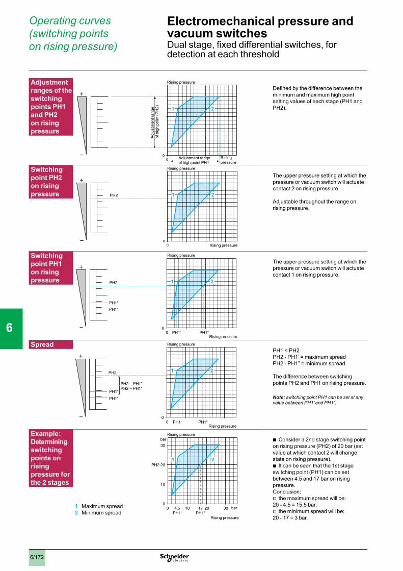
6/172
Operating curves (switching points on rising pressure)
Adjustmentranges of theswitching points PH1 and PH2 on rising pressure
Defined by the difference between the minimum and maximum high point setting values of each stage (PH1 and PH2).
Switching point PH2 on rising pressure
The upper pressure setting at which the pressure or vacuum switch will actuate contact 2 on rising pressure.
Adjustable throughout the range on rising pressure.
Switching point PH1 on rising pressure
The upper pressure setting at which the pressure or vacuum switch will actuate contact 1 on rising pressure.
SpreadPH1 < PH2PH2 - PH1’ = maximum spreadPH2 - PH1” = minimum spread
The difference between switching points PH2 and PH1 on rising pressure.
Note: switching point PH1 can be set at any value between PH1’ and PH1”.
Example: Determining switching points on rising pressure for the 2 stages
Consider a 2nd stage switching point on rising pressure (PH2) of 20 bar (set value at which contact 2 will change state on rising pressure).
It can be seen that the 1st stage switching point (PH1) can be set between 4.5 and 17 bar on rising pressure.Conclusion:
the maximum spread will be: 20 - 4.5 = 15.5 bar,
the minimum spread will be: 20 - 17 = 3 bar.
b
b
v
v
+
–0
0
1 2
Rising pressure
Rising pressure
Adjustment range of high point PH1
Adj
ustm
ent r
ange
of
hig
h po
int (
PH
2)
+
–0
0
1 2PH2
Rising pressure
Rising pressure
+
–
PH2
PH1'
PH1'
PH1"
PH1"00
1 2
Rising pressure
Rising pressure
0
+
–
PH1'
PH1"
PH2
PH2 – PH1"PH2 – PH1'
PH1' PH1"0
1 2
Rising pressure
Rising pressure
0
30
PH2 20
10
10 20 3017PH1"
4,5PH1'
0
1 2
Rising pressure
Rising pressure
1 Maximum spread2 Minimum spread
bar
bar
Electromechanical pressure and vacuum switches 0 Dual stage, fixed differential switches, for detection at each threshold
1
2
3
4
5
6
7
8
9
10
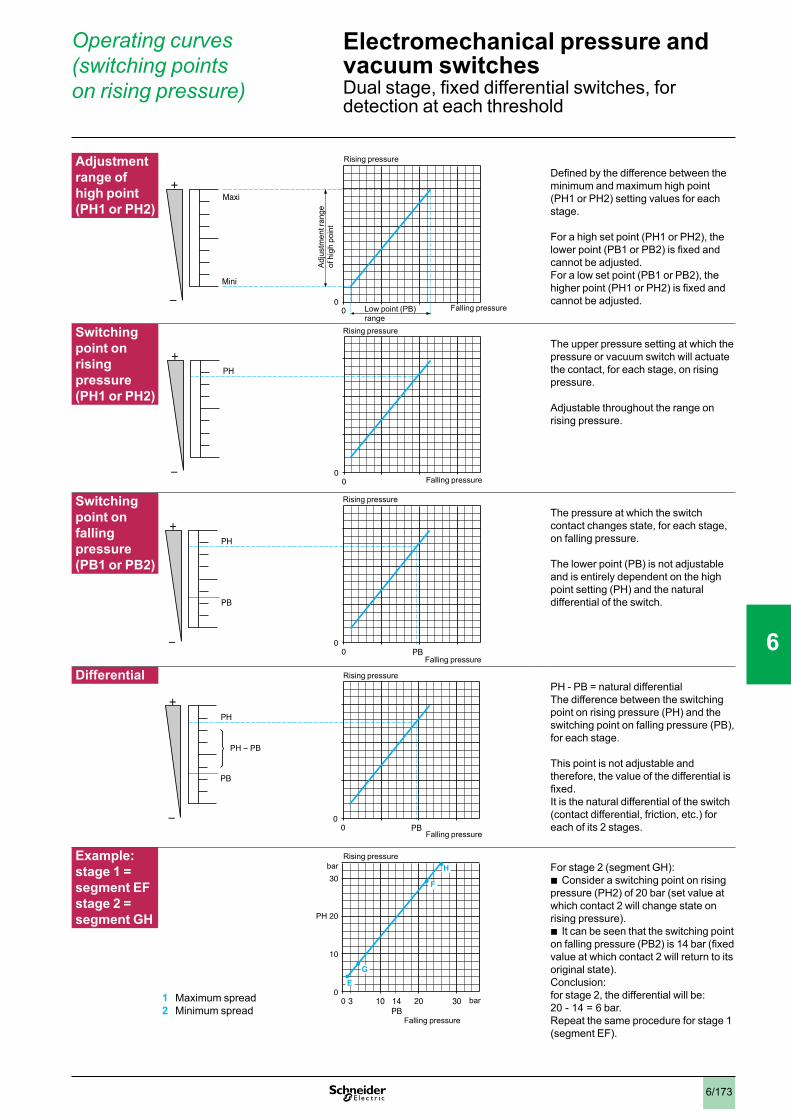
6/173
Operating curves (switching points on rising pressure)
Adjustment range of high point (PH1 or PH2)
Defined by the difference between the minimum and maximum high point (PH1 or PH2) setting values for each stage.
For a high set point (PH1 or PH2), the lower point (PB1 or PB2) is fixed and cannot be adjusted.For a low set point (PB1 or PB2), the higher point (PH1 or PH2) is fixed and cannot be adjusted.
Switching point on rising pressure (PH1 or PH2)
The upper pressure setting at which the pressure or vacuum switch will actuate the contact, for each stage, on rising pressure.
Adjustable throughout the range on rising pressure.
Switching point on falling pressure (PB1 or PB2)
The pressure at which the switch contact changes state, for each stage, on falling pressure.
The lower point (PB) is not adjustable and is entirely dependent on the high point setting (PH) and the natural differential of the switch.
DifferentialPH - PB = natural differentialThe difference between the switching point on rising pressure (PH) and the switching point on falling pressure (PB), for each stage.
This point is not adjustable and therefore, the value of the differential is fixed. It is the natural differential of the switch (contact differential, friction, etc.) for each of its 2 stages.
Example: stage 1 = segment EF stage 2 = segment GH
For stage 2 (segment GH):Consider a switching point on rising
pressure (PH2) of 20 bar (set value at which contact 2 will change state on rising pressure).
It can be seen that the switching point on falling pressure (PB2) is 14 bar (fixed value at which contact 2 will return to its original state).Conclusion: for stage 2, the differential will be: 20 - 14 = 6 bar.Repeat the same procedure for stage 1 (segment EF).
b
b
Maxi+
–
Mini
00
Falling pressure
Rising pressure
Low point (PB) range
Adj
ustm
ent r
ange
of
hig
h po
int
0
PH
+
– 0
Rising pressure
Falling pressure
0
PH
+
–
PB
PB0
Rising pressure
Falling pressure
PH
+
–
PB
PB
PH – PB
00
Rising pressure
Falling pressure
0 14PB
20 30103
10
PH 20
30
0E
G
F
HRising pressure
Falling pressure
1 Maximum spread2 Minimum spread
bar
bar
Electromechanical pressure and vacuum switches 0 Dual stage, fixed differential switches, for detection at each threshold
1
2
3
4
5
6
7
8
9
10