6. possible failures - belarus · 6. possible failures ... pipelines in hydraulic drive system. ......
TRANSCRIPT

67
6. POSSIBLE FAILURES
6.1. POSSIBLE FAILURES OF COUPLING
Fig. 6.1
1 – flywheel; 2 – center plate; 3 – pressure plate; 4 – hub of driven disc; 5 – power shaft; 6 – release lever;7 – driven plates, 8 – leverage mechanism; 9- clutch cover plate; 10- lever axle; 11- yoke; 12- bolt; 13-adjusting nut; 14 –lock plate; 15- lever spring; 16- damper; 17- floating bushing;18- clutch release bearing;19-clutch release yoke; 20- release yoke bracket; 21- cup; 22-compression spring; 23-insulating washer;24- nut;25- pin; 26-bushing; 27-driven disc damper.

68
Defect, external manifistation Troubleshooting
Coupling slipsThere is no clearance between the shifterbearing and release levers. No free travel ofthe pedal).
Adjust the clearance
Oiling of driven disks linings Reveal and eliminate the reason of oilpenetration into the dry room. If necessarywash in petrol or change driven discslinings.
Linings of driven disks are worn-out. Replace linings or assembled driven disks.
There is not enough tension ofcompression springs
Replace compression springs if tensionincrease 3 mm.
Clutch „grabs and shudders” (when putting into GB gear the clutch rattels )Increased pedal free travel Adjust
Release levers are not in plane withrelease bearing.
Adjust
Increased runout (deformation) of drivendisks.
Replace disks. Permissible runout 0,8 mmon the radius of 165 mm.
Jamming of driven disk hub on the splinesof transmission shaft.
Clean and grease the splines. When thedisks are worn out or jammed change thedisks and transmission shaft.
Bearing in the flywheel is disrupted (powershaft suport)
Replace the bearing.

69
Possible failures of hydrostatic clutch drive and guidelines for troubleshooting
Dosing pump of hydrostatic power steering
Fig. 6.2
1 -tank; 2- spring; 3, 17- bolt; 4, 8, 14, 18,27,42- nuts; 5, 15.43 - yoke; 6, 16. 34,44- pins; 7- clutchpedal for forward travel; . 12, 31,32 - pusher: 10 – main cylinder for forward travel; 11 – oil pipeline; 13- cover; 19 – main cylinder for reverse; 20 – clutch pedal for reverse; 21. 25 - pipelines; 22 - valve; 23- piston; 24 – flexible sleeve; 26 - support; 28 – protective cap; 29 – bzpass valve; 30 –workingcylinder; 33,40 - bracket; 35 – splint pin: 36 - washer: 37 - cover: 38 - piston; 39 – hzdraulic booster;41 - rod; 45 - lever; 46 – hose; 47 – backward spring.

70
Defect, external manifistation Troubleshooting
Clutch coupling does not transmit full torque (“clutch skidding")Clearance space between clutch releasebearing and release lever – “clutch isdisengaged in a half” is nil (insufficientclutch-pedal clearance)
Adjust clearance
Partial engagement of clutch coupling(clutch lever does not return to initialposition) when the clutch pedal is released,due to failure in clutch hydrostatic drive.
Detect and eliminate the cause
Clutch driven disk facing is worn out Change driven disksClutch driven disk facings are oiled-up dueto ingress of oil into dry section
Detect and eliminate the cause of oilingress into dry compartment. If necessarywash in petrol or change driven discslinings.
Poor compression spring force (springshrink due to continuous skidding andclutch overheating)
Change compression springs

71
Defect, external manifistation Troubleshooting
Clutch coupling can not be fully disengaged (“clutch grabs and shudders”)Clearance space between clutch releasebearing and release lever is increased
Adjust clearance
Clutch pedal free travel is increased AdjustInsufficient clutch lever stroke when theclutch pedal is fully depressed
Ensure full stroke of clutch lever andhydraulic amplifier piston strokeaccordingly when the clutch pedal is fullydepressed (not less than 24 mm).
Misalignment of release levers Adjust position of release leversExcessive warping of driven disks Check face runout of driven disk facings
against hub spline external diameter –shall not exceed 0,8 mm on 165 mmradius. If the failure can not be eliminated,replace the disks
Blocking of driven disk hub on transmissionshaft splines.
Clean and grease the splines. When thedisks are worn out or jammed change thedisks and transmission shaft.
Damaged transmission shaft supportbearing in flywheel
Replace the bearing

72
Defect, external manifistation Troubleshooting
The clutch lever does not go back to the initial position when releasing clutchpedal
Clearance between piston and pistonpusher of main cylinder for forward traveland reverse is nil
Adjust
Clearance between operating cylinderpusher and hydraulic amplifier push rod isnil
Adjust
Sticking of main cylinder piston (does notgo back in its initial position) due to pistoncup and O-ring expansion, resulting inclosure of compensating ports (in maincylinders of forward and reverse travel)Blocking of main cylinder piston due topiston cup expansion
Blocking of valve piston due to O-ringexpansion
Use of incorrect hydraulic-brake fluid oringress of mineral oil, petroleum, kerosene,diesel fuel into hydraulic-brake.
Rinse hydraulic drive system withhydraulic-brake fluid. Replace damagedcups and O-ring in the main and operatingcylinders. Replace hydraulic-brake fluid.Circulate hydraulic-brake fluid through thehydraulic system
Hydraulic cylinder piston strokes arecarried out with difficulty
Establish and eliminate the reasons forhard movement of hydraulic amplifierpiston. Hydraulic amplifier piston startingand movement force shall not exceed 120N
Hydraulic amplifier, operating cylinder andlever are out of alignment
Ensure alignment of hydraulic amplifier,operating cylinder and lever by shiftingplate before tightening of bracket bolts
Clogging of compensating port in maincylinder for forward travel and reverse
Unclog the compensating port of maincylinder and deaerate the system
Loss of pullback spring power Replace the spring

73
Defect, external manifistation Troubleshooting
There is no full travel of clutch lever when pressing clutch pedalThe play between the piston and pistonpusher of main cylinder for forward traveland reverse is increased (increased freepedal travel)
Adjust.
The play between the pusher of workingcylinder and pusher of hydraulic booster isincreased.
Adjust.
Presence of air in hydraulic system ofclutch control at forward travel and onreverse.
Bleed hydraulic system with brake fluid atforward travel and on reverse.
Insufficient level of brake fluid in the tank ofhydraulic system at forward travel and onreverse.
Pour the brake fluid to the tank of the maincylinder up to the level at forward travel andon reverse. Bleed the hydraulic system withbrake fluid at forward travel and on reverse.
Impermeability violation of work spaces ofthe main and operating cylinders becauseof damage, wear-out of cuffs or sealingring.
Replace cuffs and a sealing ring in themain and operating cylinder. Make surethat there are no sharp edges, high spotsor blisters on the face of the main andoperating cylinders. Bleed the hydraulicsystem with brake fluid at forward traveland on reverse.
Bleeding of brake fluid in connections andpipelines in hydraulic drive system.Hydraulic system air leak.
Tighten the connections, replace damagedparts. Bleed the hydraulic system withbrake fluid at forward travel and on reverse.

74
Defect, external manifistation Troubleshooting
Clogging of hole in piston (on reverse),causing rarefaction in the main cylinder,from which air permeates into cylinderthrough sealings.
Clean the hole. Bleed the hydraulic systemwith brake fluid at forward travel and onreverse..
Plugging of hydraulic drive pipelinesbecause of dent or clogging.
Replace pipelines. Bleed the hydraulicsystem with brake fluid at forward traveland on reverse.
Leak of oil through hydraulic boostersealing rings.
Replace sealing rings in hydraulic booster.
Insufficient clutch pedal travel (pedalstriking cab wall)
With a help of yokes of main cylinderspiston pushers and adjusting bolts extendclutch pedal full travel at forward travel andon reverse.
Adjust clearance space between forwardand reverse main cylinder piston and pistonfollower Circulate hydraulic-brake fluidthrough the hydraulic system.
The stroke of forward and reverse maincylinders pushers shall be not less than 35mm. The stroke of booster piston and ofclutch engage lever when the pedal is fullydepressed shall be not less than 24 mm.

75
Defect, external manifistation Troubleshooting
No pressure on clutch pedals on reverse. Presence of air in hydraulic system. Cuffsand a ring in the main and operatingcylinder are worn-out.Replace cuffs and a sealing ring in themain and operating cylinder. Make surethat there are no sharp edges, high spotsor blisters on the face of the main andoperating cylinders. Bleed the hydraulicsystem with brake fluid on reverse.
Misalignment of hydraulic booster, workingcylinder and coupling lever
Achieve coaxiality of hydraulic booster,working cylinder and lever by means ofmoving of booster bracket and bracket ofworking cylinder support fastening beforetightening of bolts.
Flexible hose increases in volume, blowsup, elongates.
Replace flexible hose.
It is impossible to blow the system of hydraulic drive in reverse mode (BELARUS1221B/1523B)
Damage or worn-out of sealing ring of maincylinder rod of reverse.
Change the sealing. Blow the system.

76
6.2. POSSIBLE FAILURES IN GEARBOX AND GUIDELINES FOR TROUBLESHOOTING(Fig. 6.3)
Defect, external manifistation Troubleshooting
Low pressure in hydraulic system
Insufficient quantity of oil in transmission. Add oil in case up to a label “ “ on glass of
oil-gauge glass.
Pollution of screen filter of hydrosystem Wash out filter.
High pressure in hydraulic system
Sticking of valve for filter-distributor control. Wash out valve of filter distributor.
The channels for oil drain in transmission
are clogged.
Wash out drain channels.
No pressure in hydraulic system
Hydraulic system pump drive is off Switch on the pump
Insufficient quantity of oil in transmission Add oil in case up to a label “ “ on glass of
oil-gauge glass.
Increased noise during gear shifting
Coupling clutch is not fully disengaged Adjust coupling clutch
Wear of cone surfaces of synchronizers
and gears
Change worn-out parts.

77
Defect, external manifistation Troubleshooting
Increased noise
Insufficient quantity of oil in transmission. Add oil in case up to a label “ “ on glass of
oil-gauge glass.
Wear and breakdown of bearings and other
parts of transmission.
Change bearings and other elements.
“L or H” pass of GB reducing gear can not be engaged (GB 24F +12R)Maladjustment of sensor (switch) of gear
shifting lever neutral position
Adjust the sensor with a help of shims. In
neutral position of lever the electric circuit of
electro-hydraulic distributor shall be closed.
Circuit opening of GB reducing gear shifting Elimitate opening
Sticking or jamming of sleeve valve of electric-hydraulic distributor
Rinse valve spool. Replace valve ifnecessary

78
Transmission hydraulic system
1. intake filter; 2. gear pump; 3. safety valve; 4. intake filter; 5. rear axle differential lubrication; 6.filter-distributor; 7. electrohydrodistributor; 8. coupling of rear axle differential lock; 9. channelsfor oil supply to the GB shafts; 10. GB input shaft; 11. transmission main shaft; 12. lubricationof rear axle planetary group; 13.GB low gears shaft; 14. hydraulic cylinder of PTO drive; 15.PTO control valve; 16. hydrocontrolled multiple-plate clutch of FDA drive.

79
6.3. POSSIBLE FAILURES IN REAR AXLE AND GUIDELINES FOR TROUBLESHOOTING
Defect, external manifistation TroubleshootingIncreased noise of the main gear
Improper adjustment of gearsengagement of main gear according tothrough tooth-contact pattern and sideclearance
- adjust of gears engagement of main gearaccording to through tooth-contact pattern;- adjust side clearance in engagement ofmain pair
Improper adjustment of conical bearingsof main gear
Adjust bearing preload.
Not enough oil in transmission Refill oil up to oil level markGear teeth damage Check the condition of gear tooth ring.
There shall not be any chippage anddamage. Gears with damaged teeth shallbe replaced in pairs
The differential lockup does not function:Lock clutch disks are oiled. Eliminate oil leakage, wash out discs.The lockup clutch plate friction surfaces areworn out.
Change the plates.
The lockup clutch diaphragm is damaged. Change the diaphragm.Low pressure of oil fed into the lockupactuator.
Check the oil pressure applied to the lockupclutch. It shall be 9-10 kgf/cm2 at the oilviscosity within 18...26 mm2/s).
Lockup control electrohydraulic valve isinoperative.
Check safety fuses, relays and other circuitcomponents for operability and the slidevalve for easy and smooth travel; eliminatethe fault.

80
Defect, external manifistation Troubleshooting
Low pressure in the hydraulic system of the transmission
Lack of oil in the transmission housing. Add oil to the “ ” (Full) mark.Clogging of the hydraulic system screen. Wash the screen.Seizure of the overflow valve in thedistributing filter.
Flush the distributing filter valve.
High pressure in the hydraulic system of the transmissionSeizure of the overflow valve in thedistributing filter.
Flush the distributing filter valve.
No pressure in the hydraulic system of the transmission
The drive of the hydraulic system pump isOFF.
Turn the pump ON.
Lack of oil in the transmission housing. Add oil to the “ ” (Full) mark.Excessive noise when shifting gears
The clutch fails to disengage fully (theclutch “drags”).
Adjust the clutch.
The cone surfaces of the synchronizers andgear surfaces are worn-out.
Replace the worn-out parts.
Excessive noise:
Lack of oil in the transmission housing. Add oil to the “ ” (Full) mark.Bearings and/or other parts of thetransmission are worn-out or broken.
Replace the bearings and/or other parts asnecessary.

81
6.4 POSSIBLE FAILURES OF BRAKES AND GUIDELINES FOR TROUBLESHOOTING
Fig. 6.4
Failure, external manifestation Troubleshooting
Underperformance of brakes
No free travel of pedals Adjust pedal free travel in accordancewith the Operation manual. Clean and rinsethe cylinders 1 and 2. Bleed the system.
Swelling and seizing of cuffs of the mainand service cylinders due to use of non-recommended or contaminated brake fluids.
Clean and rinse the cylinders 1 and 2.Replace the cuffs and the cylinders. Fill inclean cooling fluid.
Uneven braking of left and right wheels.
Malfunctioning of leveling valves of mainbrake cylinders
Disconnect the leveling valve pipe, dothe fittings out and dismount the levelingvalves from the main cylinders. Replace theworn-out parts or the main cylinderassembly. Bleed the system.
Uneven breaking of rear wheels exceeds0.5 m (acc. to the track )
Adjust the brakes.
Increased heating of breaks. Check brake housings for presence ofoil. If required top up the oil to the checkplug level.

82
6.5.1 POSSIBLE FAILURES OF PTO WITH BAND BRAKES (fig. 6.5, 6.6)
Failure, external manifestation Troubleshooting
Rear PTO does not transmit full torque or continues to turn when disengaged
Maladjustment of PTO controlmechanism (dimension >80 mm withPTO engaged and <32 mm with PTOdisengaged).
Adjust the PTO control mechanism, to do this carry outouter adjustment of band brakes. If the recommendeddimensions “ ” could not be obtained by means of thisadjustment carry out the inner adjustment of brakes.
Wear of brake bands. Replace the worn pats.
Wear or failure of PTO reductiongroup parts. Replace the damaged parts.
With the PTO turned on thecylinder rod will not move. Low oilpressure in transmission hydraulics.
1. Shortage of oil in transmission hydraulics. Top up.2. Contamination of hydraulics strainer. Rinse the
strainer.3. Sticking of an over-flow valve of the distributing filter.
Wash the valve.NOTE: Define oil pressure value in the hydraulics with
a pressure gauge (the scale shall be up to 1.5 MPa, thegraduation mark - 0.05 to 0.1 MPa), screwing that instead ofthe threaded plug into the plate of the PTO actuator engagingelectrohydraulic valve group. The oil pressure value shall notbe lower than 0.9 +0.1 MPa.

83
Control hydraulics of rear PTO with band brakes
Figure 6.51 - lever; 2 - spring; 3 - pipeline; 4 – cock; 5 – link rod; 6 – handle; 7 – oil pipeline; 8 – oil pipeline;
9 – pipeline; 10 – cylinder; 11 – ADL electrovalve (for references)The dimension “ ” in position “PTO on” shall make 66±3 mm and in position “PTO off” - 46±3 mm.
Adjustment of rear PTO with band brakesControl shaft
Figure 6.6The external manifestation, pointing at the wear rate of brake band facings and the necessity of
performing adjustment operations is the dimension “ ” between rod head top and the cap of the PTOactuation hydraulic cylinder. When the PTO is well-adjusted and unworn the dimension “ ” shall be asfollows:
66±3 mm (PTO on);46±3 mm (PTO off).If the value is > 80 mm (PTO on) and value is < 32 mm (PTO off) and also in case of PTO
skidding it is required to adjust the clearance in the band brakes

84
Failure, external manifestation Troubleshooting
Failure of PTO control adjustment Adjust the cable control of PTO.
Low pressure of oil in transmissionhydraulics.
1. Shortage of oil in transmissionhydraulics. Top up.
2. Contamination of strainer oftransmission hydraulics. Rinse the strainer.
3. Sticking of the over-flow valve of thedistributing filter. Rinse the valve.
NOTE: Oil pressure value in thehydraulics with shall be measured with apressure gauge (the scale shall be up to 1.5MPa, the graduation mark - 0.05 to 0.1 MPa),screwing that instead of the threaded plug intothe plate of the PTO actuator engagingelectrohydraulic valve group. The oil pressurevalue shall not be lower than 0.9+0.1 MPa.
Low oil pressure at the outlet to thefriction clutch and PTO brake due to:
1. Increased oil leakage in thevalve group or in friction and in brake
2. Jamming of control valvespool.
Check oil pressure, delivered to thefriction clutch and the brake. If requiredreplace sealing rings of the friction clutch andthe brake of the PTO gear group or the valve.
Dismount the control valve. Clean andrinse the parts, eliminate the jamming causes.If required replace the faulty parts.
Fault in operation of friction clutchand brake because of piston jamming.
Rinse the parts of the friction clutch and thebrake.
Wear of friction plates. Replace the worn parts.
6.5.2 POSSIBLE FAILURES OF PTO EQUIPPED WITH PLANETARY GEAR GROUPWITH FRICTION PLATES

85
Figure 6.7
1 – c ro wn gear ; 2 – sha ft ; 3 – sa t e l l it e ge ar ; 4 – sa t e l l it e gear s ha ft ; 5 – ca r r ie r ;6 – sha ft ; 7 – e xcha ngea b le s ha ft end ; 8 – plate; 9 – bolt 10 18; 10, 25, 26, 30 – bearing;11, 21 – coupling; 12 – sun gear; 13, 22 – f r ic t io n p la t e ; 14 – cas ing ; 15, 16 – p is t o n ; 17,18 – t hr u s t d is k ; 19 – driving plate; 20 – pressure plate; 23 – spring; 24 – nut; 27 – cover 28 –shift collar; 29 – cage; 31 – screw.
IT IS NOT REQUIRED TO ADJUST THE PTO GEAR GROUP!THE PTO EQUIPPED WITH BAND BRAKES CAN BE REPLACED WITH THE PTO EQUIPPEDWITH DISK BRAKES ONLY TOGETHER WITH CORRESPONDING REPLACEMENT OFREAR AXLE HOUSING.

86
Control of planetary gear group of rear PTO with friction plates (fig. 6.8)
The rear PTO does not transfer a full torque or continues to turn when disengaged
Low pressure in transmission hydraulics eliminate the cause
Friction plates worn-out replace the platesFailure of seals in service pistons of PTO gear
groupreplace rubber seals
Oil leakage out of seals of PTO gear group andPTO control valve
replace the seals
Attention: there is no need to adjust the gear group with friction plates during the whole servicelife of the tractor!
Figure 6.8
1-distributor; 2-oil takeoff pipeline; 3-drain pipeline; 4-pipeline of service brake control; 5-pipeline of parking brake control
To prevent impact loads on the PTO reduce the engine speed to 900 rpm with the PTO engaged,then increase the engine speed. To reduce load on PTO parts, reduce the PTO speed at first byreducing the engine rpm before turning the PTO off. This is primarily important for the implementswith big inertia moment. Such implements shall always be equipped with a free-wheel clutch.
Three PTO shaft ends are provided for. When operating the 6 or 8-splined shaft end set the enginespeed to 2037 rpm in order to obtain the standard PTO speed of 540 rpm.

87
6.6 POSSIBLE FAILURES OF FDA
Symptoms and causes of failure Remedy
As tractor moves with the wheels turnedagainst the stop there is noise in the geargroup.
Check the PTO actuation mode (it stay in“Off” or “Automatic” position)
Check the critical turning angle of thewheels. If required adjust it to stay within 38to 40°.
Noise and heating in the main gear area.
Check the pinion and the gear for axialplay. If required adjust the gear bearings tohave a preload of 0.01 to 0.10 mm, and thepinion bearings to have a preload of 0.02 to0.05 mm.
Check the value and the location of thecontact point. Adjust it if necessary.
Knocks in steering axis during travel.
Check the pivot bearing adjustment. Ifrequired adjust the bearings to have a preloadso that the force of turning of the gear grouphousing round the pivot axis, applied to theflange, made 60 to 80 N.
Knocks by sharp turn of the wheels.Check attachment of the pins of the
steering link and the swing hydraulic cylinder.If required eliminate the play.
Oil leakage through the gear groupbreather.
Check oil in the gear group. Drain theexcessive oil.
Do the breather out of the gear groupcasing and clean it out. Rinse or replace thesupplementary foamed rubber filter.
88
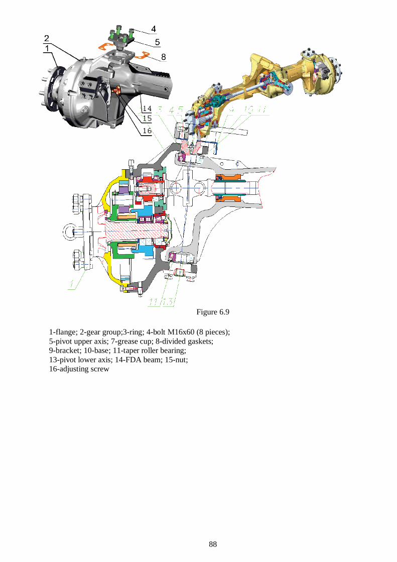
Figure 6.9
1-flange; 2-gear group;3-ring; 4-bolt 16 60 (8 pieces);5-pivot upper axis; 7-grease cup; 8-divided gaskets;9-bracket; 10-base; 11-taper roller bearing;13-pivot lower axis; 14-FDA beam; 15-nut;16-adjusting screw

89
6.7 HYDRAULIC LIFT FAULT DIAGNOSTICS
Hydraulics failure Failure cause Failure repair procedure
1.No weightedhitch elevation or slowelevation.
Breakdown either of a pump,or the RP-70 valve group, or thedistributing valve group.
Check the pressure and thevolume pump rate under normalengine rpm. With pressure of 16.0MPa, the volume pump rate shall beat least 40…50 l /min. Renew thepump, if required.
If the pump is without fail,check the volume pump rate underthe same conditions for one of theoutputs of the RP-70 section valvegroup. If the distributor is withoutfail, the difference in volume pumprate shall be no more than 3…3.5l/min.
If during examination thepressure is unstable or the volumepump rate loss is more than 3.5l/min, the fault is because of RP-70valve group.
2. No weightedhitch elevation orhitch lifting powerfall-off because ofRP-70 valve group (orRS-213 "Mita") fault.
) blocking of spray nozzle 14in plunger 12 of the blow-offvalve of the RP-70 valve group;
b) sticking of plunger 12 of theblow-off valve;
c) seal failure of needle 10 ofthe blow-off valve because ofparticulate matter in oil;
d) damage of rubber joint 18or fluoroplastic joint 17 ofseating 11;
e) damage of rubber joint 16 orfluoroplastic joint 15 of the blow-off valve.
), b), c) – screw out thefitting 7 of the blow-off valve fromcasing 6 of cover 4 of the RP-70valve group and, without disturbingthe control settings (that is, withoutturning back cover nut 9 or lock nut8) demount the blow-off valve topieces and wash the piecesthoroughly. Check spray nozzle 14flotation in plunger 12;
d), e) – renew the damagedrubber joints 16 & 18 orfluoroplastic joints 15, 17.
After having reassembled thesystem, place back the offloadedpieces of the blow-off valve andcheck the hydraulics performance.

90
Blow-off valve of the RP-70valve group.
3. No weightedhitch elevation orhitch lifting powerfall-off because ofvalve group controlfault.
) sticking of control spool13 in casing 1 because ofparticulate matter in oil;
b) sticking of relief valve 2abroach;
c) clogging of spray nozzle7 of isolation valve 3;
d) damage of rubber 29,29 , or 29 or fluoroplastic 30 or30 gaskets on casing 1.
) set both levers of the valvegroup control (position and draftcontrol levers) to forward mostposition and lower the hitch tolowermost position.
Press the push rod 31 in orderto sink it in the upper cover andmeasure the push rod 31 protrusionabove the cover.
Set the position lever to therearmost position and measure thepush rod 31 protrusion again.
The difference in indicationsshall be at least 7 mm.
If the push rod travel is 7 mmand more, the spool 13 of the valvegroup control is without fail.
If the push rod travel is lessthan 7 mm, the valve group controlshall be dismounted, its piecesshall be washed thoroughly, and, ifrequired (should there be anyscuffs), the spool 13 shall bereseated in the casing bore.
b), c) – dismount the valvegroup control.
Unscrew plug 11, removerelief valve 2, and wash the valveand its seating in casing 1 withdiesel fuel.
Screw out isolation valve 3from the relief valve 2 and checkspray nozzle 7 flotation.
When reassembling thesystem, screw the isolation valve 3with glue into the relief valve 2.
d) renew the damaged rubber29, 29 , or 29 or fluoroplastic 30or 30 gaskets of the valve groupcontrol casing.
After having reassembled thesystem, install the valve groupcontrol into the hydraulic liftcasing and check the performance.
4. The pump will notunload after the upliftcompletion intransport position ofthe linkage.
The position of the swing leverswith regard to the limit stop 19 ofthe position sensor 18 isdisturbed.
Detach the lifting rods of thelinkage from the swing levers of thehydraulic hoist.
Do the bolts on the turn shaftends out.

91
After the uplift iscompleted there comesa distinctive noisefrom the pump,running the max.pressure, the failurebecomes apparent onlywith the linkage fullyuplifted (the pump willunload as the uplift isincomplete)
Take the swing levers off thesplines and displace them by onespline down to the cylinderdirection.
Lock the swing levers on theshaft with the plates, doing the boltsin.
5. Increased oiltemperature (above80º ) in the tank.
The pump isconstantly runningunder the load (thepressure above 20MPa) with the linkageuplifted with theimplement. As theposition handle isshifted forward to thefirst lowering thepump will not unload.Inner tightness is ok –with the engine killed(or the pump off) thelinkage with theimplement having theweight of not less than800 kg will lower fromthe transport position(cylinder shrinking) bynot more than 25 mmin 5 min.
) Fracture or shrinkage ofspring 6 of isolation valve 3.
Seal failure of ball 5 of theisolation valve 3;
b) seal failure of ball 26 ofthe counterbalance valve.
Take the distributing valvegroup off the hydraulic hoist;
) screw the plug 11 out andremove the discharge valve 2;
Screw the isolation valve 3 outof the discharge valve 2 anddisassemble it.
Measure a length of the spring6. Should the spring length be lessthan 12 mm or should it bedeformed, replace the spring.
Throw the ball into thehousing 4, put the housing in thevertical position and check tightnessof the ball filling in fuel. Herewithclose the side jet orifice 7.
If the fuel level dropssignificantly within 2 to 3 minutes,impress the ball in the seating 5 byslight thrusts of the hammer on theworkholder.
Assemble the valve group andmount it into the hydraulic hoist.
b) screw the taper plug 28out.
Take the spring 27 out as wellas the ball 26 of thecounterbalancing valve.
Rinse the spring 27, the ball26 and the seating in the housingwith diesel fuel.
Impress the ball (through theworkholder) to the seating in thehousing.

92
Assemble and mount thedistributing valve group into thehydraulic hoist.
6. Increased oiltemperature (above80º ) in the tank.
The pump isconstantly runningunder the load (thepressure above 20MPa)
As the positionhandle is shiftedforward the pump willunload for a shorttime.
Failure of innertightness (with theengine killed or withthe pump off thelinkage with theimplement will lower)
) fracture of rubber sealrings 29, 29a, 29 in the outergrooves of the casing 1 of thedistributing valve group.
Seal failure of ball 23 of theantishrinking valve;
b) fracture of the rubber sealring on the plug 25 of theantishrinking valve.
Take the distributing valvegroup out of the hydraulic hoist;
) check the state of the rubberrings 29, 29 , 29 . If damagedreplace them;
b) unscrew the plug 25 of theantishrinking valve, take out thespring 24 and the ball 29, inspect theorifice surface in the seating,impress the ball 23 to the seatingusing the workholder in thehousing.
Check the state of the seal ringon the plug 25 and replace it ifrequired.
Assemble and mount thedistributing valve group into thehydraulic hoist housing.
7. The weightedlinkage goes down byitself with the enginekilled (or with thepump turned off).
“Often” correction.Oil heating is possible.
Outer leakage ofoil over the plunger ofone or both cylinders.
Failure of gaskets 5 ofactuating cylinders
Take the plunger 3 out of thecasing 1, having previously transferredthe lock ring 2 to the mounting groove“A”.
Replace the gasket 5 havingarranged it as shown in the figure.
Assemble the cylinder in areverse order.
8. High vibrationof the linkage whenlowering theimplement.
May occur whenheavy implementswith 2000kg weightare lowered.
Fracture or shrinking of thespring 19 of the slowdown valve18.
Fracture of limit stop 20.
Take the distributing valvegroup off the hydraulic hoist;
Squeeze the pull-back spring17 to release the dowel 16 and takeit out of the hole in the spool 13,hereby holding the outer limit stop15.

93
Measure the length of thespring 19. If the length is below 61mm or the spring is deformedreplace the spring. Should the limitstop 20 be deformed replace it.
Assemble the distributingvalve group in a reverse order.
9. The controlhandles (position anddraft control) will nothold in a set positionon the control panel.
Self-shifting –slipping of one or bothhandles forward in thedirection of linkagelowering.
The tightening is loosened orthe friction washers securing thehandles 5 and 6 are worn out.
Adjust the nuts 4 and 7 onthe shaft of the bracket 2 bytightening the friction washersuntil the fault is eliminated.
10. Position of thecontrol handles(position and draftcontrol) on figures“0” and “9” will notcorrespond totransport andlowermost positionsof the linkage.
The cylinderplunger stroke is lessthan 190 mm
Failure of cable adjustment ofhandle position on control panel.
Adjust the control cables 1(see points 8-21 above)

94
Hydraulic valve group RS-213 “Belarus” (HLL with draft control)
Figure 6.101 - special wrench; 2 – needle; 3 – acceleration valve; 4 -section valve group; 5 - bypass valve; 6 - bolt of the swivelangle.
The section valve group RS-213 «Belarus» 4 with bypass valve 5 of cartridge type is very sensitiveto the pollution of oil in the hydraulics. Dirt in the hydraulic system can cause seizing of the bypassvalve or clogging of throttle orifice « » in the seat of the acceleration valve 3. This will lead to theopening of the bypass valve and oil will drain (the draft control system as well as the remote hydrauliccylinders will not operate).
Do the following to fix the problem:1. Remove the left and the back panel of the instrument board cover;2. Do the bolt 6 out of the swivel angle and the bypass valve 5 to have access to the acceleration
valve 3.3. With the help of the needle 2 clean the throttle orifice « » (Ø 1,3…1,4 mm) of the acceleration
valve; if necessary, unscrew the valve with the help of special wrench, rinse it in clean diesel oil and blowwith compressed air, mount the valve in place;
4. Inspect the bypass valve 5 and make sure that the plunger moves easily. If necessary, pull down thevalve, rinse the parts in clean diesel oil and attain the free movement of the plunger; assemble the valve;
5. Mount the bypass valve 5 and bolt 6 of the swivel angle in place;6. Start the engine and check functioning of the hydraulic system;7. Mount the panels of the instrument board cover in place.

95
6.8 ELECTRICS TROUBLESHOOTING
Power supply system
Figure 6.11The voltage converter UZ1 is an electronic device intended to charge the second battery GB2 by
converting and adjusting charge voltage, its operation is based on the principle of conversion.The converter stable operation depends on availability of a non-faulty negative circuit on the
converter body.

96
Power supply system
Figure 6.12To protect the converter at hazards it is provided as follows:- mounting of a fuse for 20A current in “+ 2” circuit, in the converter body;- the converter operation is blocked until voltage from the “ ” terminal of the alternator is delivered
to it (this voltage appear only as the alternator turns on after the engine start-up) and no voltage isconverted;
- should the input voltage increase up to 15.4 – 16V and the converter temperature up to +125° theconverter will also get blocked; To test operability of the power supply system the following componentsare provided on the tractor dashboard:
- voltage dial with scale range of 10-16V, which is intended to control the charge state of thestorage battery GB1 and the operability of the alternator G1;
- pilot lamp (red LED) is mounted in the voltage dial body and is linked to the terminal “K” of thevoltage converter; it will light up when the charging current in the “+ 2” circuit of the converter goesdrops to 0.5A and below.
The pilot lamp operation algorithm is as follows:- the pilot lamp is on with the dials on before the engine is started – this points at consistency of the
control circuit “K” and at readiness of the converter for operation (the “+ 2” circuit is not powered);- after the engine is started the line “+ 2” is exposed to current and the pilot lamp will go out thus
confirming the storage battery GB2 is being charged.

97
Power supply system
Figure 6.13
Figure 6.14
To avoid failure of the governor relay it is not allowed to check operability of the alternator bydisconnecting the battery leads or by turning off the ground switch with the engine running!

98
Engine start-up facilitation system
Figure 6.15
2-heating plug 11 720 720 (23 volts); 1-heating plugs relay;
1-heating plugs unit ; HG-pilotlamp unit AP 10.3803;
SA9-starter and instrument switch 1202.3704-03.
The wiring of the engine start-up facilitation system is connected with the tractor starting system,namely, the heating plugs rated voltage corresponds to the starting system rated voltage. If the startingsystem rated voltage make 24V, heating plugs will the 24V plugs, respectively, hereby the tractor on-board voltage will be 12V. This wiring solution is widely applied to “Belarus” tractors.
The heating plugs unit KT1 (electronic unit) is one of the basic components in this system. As shownin the diagram the unit controls directly the electromagnetic relay K1 and the pilot lamp in the pilot lampunit HG1.
Its functions are as follows:- controlling the heating plugs operation mode;- delivering the information to the driver in the form of pilot lamp indication on the dashboard;- controlling the system operability and watching emergencies. The electromagnetic relay K1 is a heavy-duty relay intended to switch the heating plug power
circuit. The relay coil rated voltage is 12V and has a polarity. The 24V plugs are connected through therelay contacts.
The electronic unit controls the electromagnetic relay which in its turn switches the heating plugpower circuit. The electronic unit runs automatically in one of preset modes. However, some function ofchoosing the mode is assigned to the driver who will estimate the situation basing on the engine (ambient)temperature mode.
99
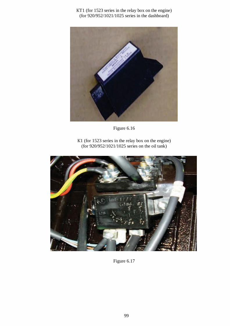
1 (for 1523 series in the relay box on the engine)(for 920/952/1021/1025 series in the dashboard)
Figure 6.16
1 (for 1523 series in the relay box on the engine)(for 920/952/1021/1025 series on the oil tank)
Figure 6.17