6. induction motors - university of florida · an induction motor has the same physical stator as a...
TRANSCRIPT
Induction MotorsInduction Motors
Revised October 6, 2008
EEL 3211 (© 2008, H. Zmuda) 6. Induction Motors 1
Induction Motors:
We just learned how damper or amortisseur windings on a synchronous motor could develop a starting torque without the necessity of supplying an external current to the field windingnecessity of supplying an external current to the field winding.
This idea works so well that a motor can be made without the synchronous motors main field windings at all.
A machine with only amortisseur windings is called an induction ac e w o y a o sseu w d gs s ca ed a inductionmachine.
These machines are called induction machines because the rotorThese machines are called induction machines because the rotor voltage, and hence the rotor current and rotor magnetic field is induced in the rotor windings instead of being physicaly connected
EEL 3211 (© 2008, H. Zmuda) 6. Induction Motors 2
by wires.
Induction Motors:
The distinguishing feature of an induction machine is that no DC field current is required to run the machine.
Although an induction machine can be used as either a motor or a generator, it has many problems when used as a generator and so these are rare.
For this reason, when studying induction machines are really o s easo , w e s udy g duc o ac es a e ea ystudying induction motors.
An induction motor is called a singly excited machine (as opposedAn induction motor is called a singly excited machine (as opposed to a doubly excited machine) because power is applied only to the stator.
EEL 3211 (© 2008, H. Zmuda) 6. Induction Motors 3
Induction Motors:
An induction motor has the same physical stator as a synchronous machine but with a different rotor construction.
There are two different types of induction motor rotors.
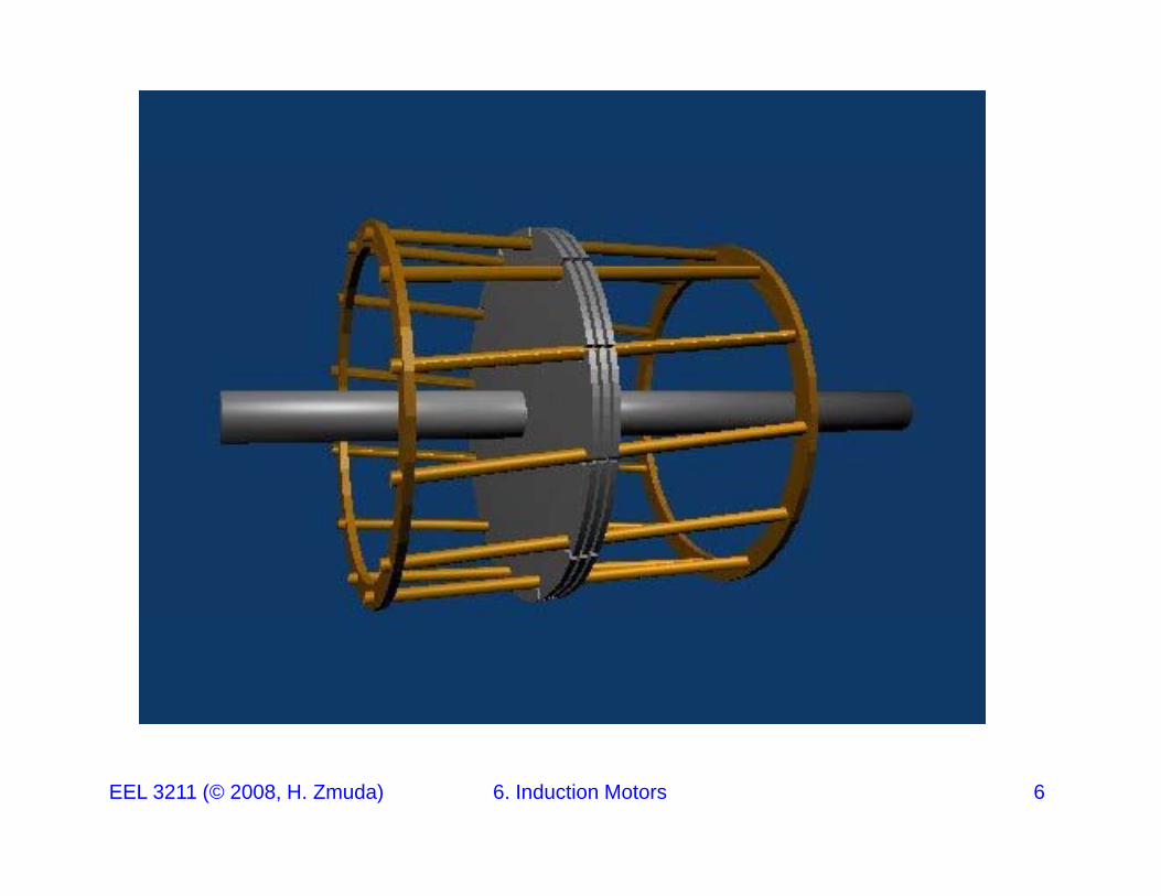
1. A squirrel cage induction motor rotor consists of conducting bars laid into slots carved in the face of the rotor and shorted at either end by end rings or shorting rings (see picture next page).e d by e d gs o s o g gs (see p c u e e page).
2. A wound rotor that has a complete set of three phase windings that are mirror images of the windings on the statorthat are mirror images of the windings on the stator.
EEL 3211 (© 2008, H. Zmuda) 6. Induction Motors 4
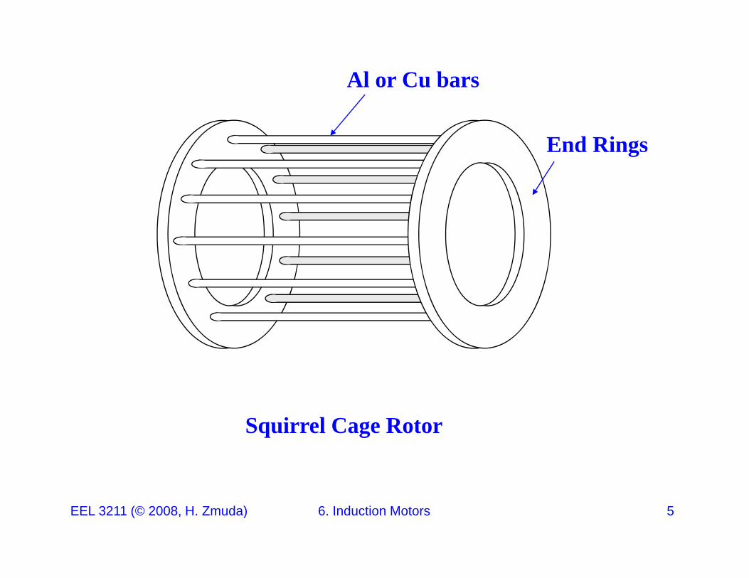
Al or Cu bars
End Rings
Squirrel Cage Rotor
EEL 3211 (© 2008, H. Zmuda) 6. Induction Motors 5
EEL 3211 (© 2008, H. Zmuda) 6. Induction Motors 6
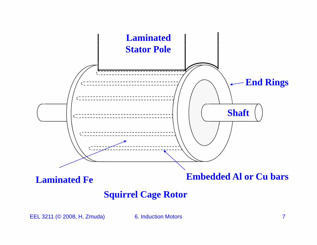
LaminatedStator Pole
End Rings
Shaft
Squirrel Cage Rotor
Embedded Al or Cu barsLaminated Fe
EEL 3211 (© 2008, H. Zmuda) 6. Induction Motors 7
X
X
X
AppliedAppliedAC Voltage
EEL 3211 (© 2008, H. Zmuda) 6. Induction Motors 8
Induction Motors:
A wound rotor that has a complete set of three phase windings that are mirror images of the windings on the stator. The three phases of the rotor windings are usually Y Connected and the ends ofof the rotor windings are usually Y-Connected, and the ends of the three-phase wires are tied to slip rings on the motor’s shaft.
The rotor windings are accessed through brushed riding on the slip rings.
Such a rotor arrangement is more expensive, requires maintenance, and hence is rarely used.
We will not consider wound rotors any further in this course.
EEL 3211 (© 2008, H. Zmuda) 6. Induction Motors 9
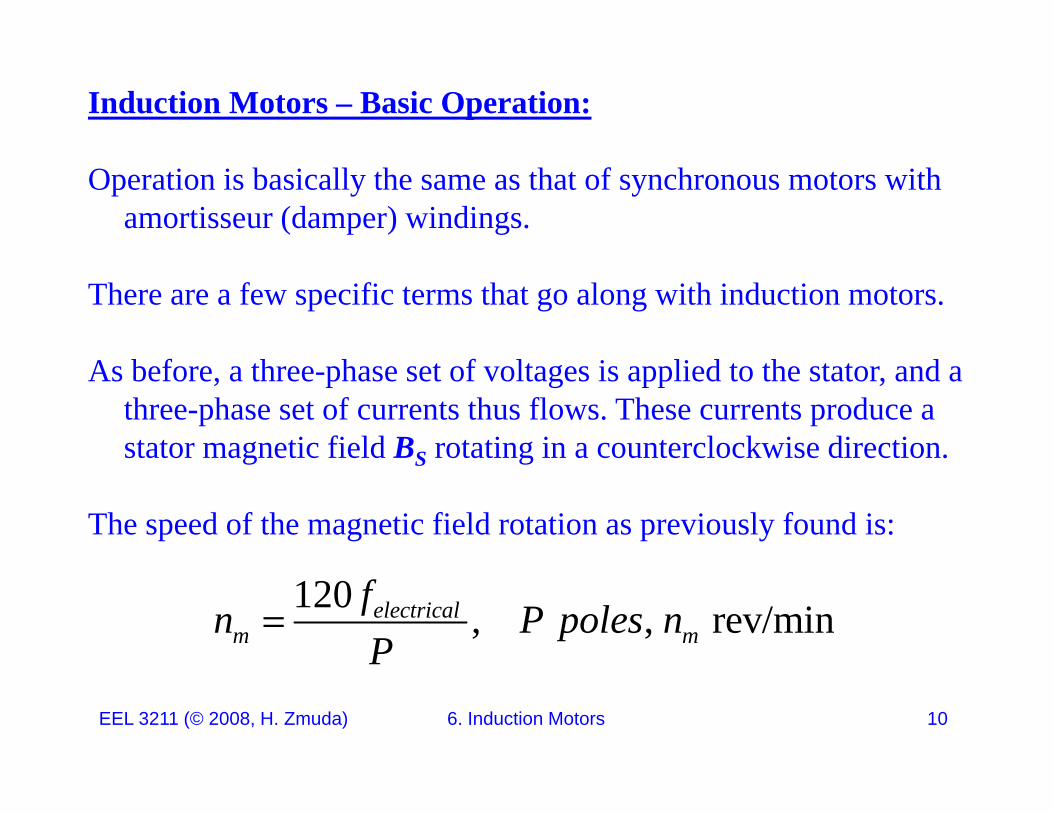
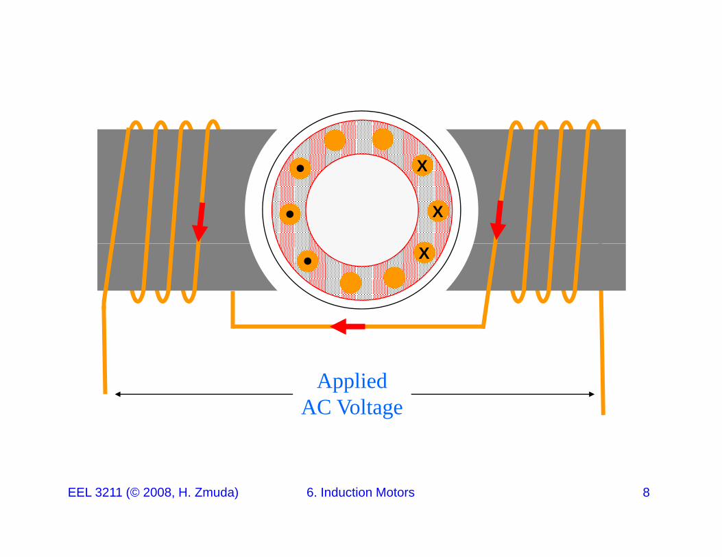
Induction Motors – Basic Operation:
Operation is basically the same as that of synchronous motors with amortisseur (damper) windings.
There are a few specific terms that go along with induction motors.
As before, a three-phase set of voltages is applied to the stator, and a three-phase set of currents thus flows. These currents produce a stator magnetic field BS rotating in a counterclockwise direction.s a o ag e c e d S o a g a cou e c oc w se d ec o .
The speed of the magnetic field rotation as previously found is:
120 , , rev/minelectricalm m
fn P poles nP
EEL 3211 (© 2008, H. Zmuda) 6. Induction Motors 10
P
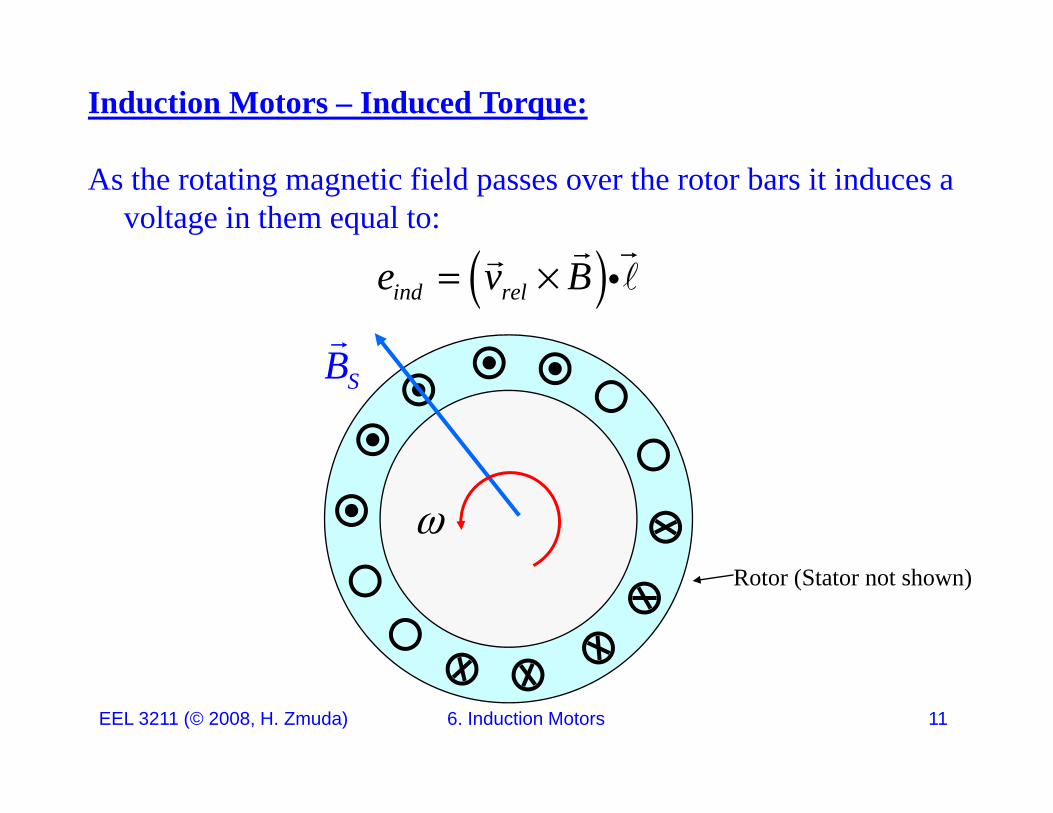
Induction Motors – Induced Torque:
As the rotating magnetic field passes over the rotor bars it induces a voltage in them equal to:
B
ind rele v B
SB
Rotor (Stator not shown)
EEL 3211 (© 2008, H. Zmuda) 6. Induction Motors 11
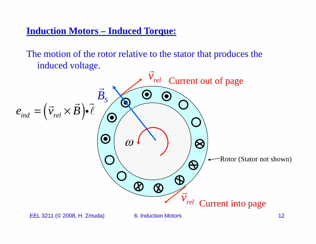
Induction Motors – Induced Torque:
The motion of the rotor relative to the stator that produces the induced voltage.
v
SB
B
relv Current out of page
ind rele v B
Rotor (Stator not shown)
v
EEL 3211 (© 2008, H. Zmuda) 6. Induction Motors 12
relv Current into page
Induction Motors – Induced Torque:
But since the rotor is inductive, current lags the induced voltage
MaximumI
SB
Maximuminduced currentRI
Rotor (Stator not shown)
EEL 3211 (© 2008, H. Zmuda) 6. Induction Motors 13
Induction Motors – Induced Torque:
This rotor current produces its own magnetic field BR.
I
SB RI
RB
Rotor Only
EEL 3211 (© 2008, H. Zmuda) 6. Induction Motors 14
(Stator not shown)
Induction Motors – Induced Torque:
The resulting torque is counterclockwise: ind R SkB B
SB
RB
Rotor Only
EEL 3211 (© 2008, H. Zmuda) 6. Induction Motors 15
(Stator not shown)
Induction Motors – Induced Torque:
Note how the maximum motor speed is the synchronous speed.
If the motor however was tuning at synchronous speed then theIf the motor however was tuning at synchronous speed then the relative velocity between the rotor and stator would be zero. With zero relative velocity,
,ind rel ind R Se v B kB B
and the rotor would slow down due to friction But then the relative
0 0 0 0 0rel ind R R indv e I B
and the rotor would slow down due to friction. But then the relative velocity would no longer be zero and the rotor would once again accelerate.
EEL 3211 (© 2008, H. Zmuda) 6. Induction Motors 16
Induction Motors – Rotor Slip
Consequently the motor will speed up to near synchronous speed but never actually reach it.
Note also that both the rotor and stator magnetic fields rotate together at synchronous speed nsync, while the rotor itself always turns at a slower speed.
This called rotor slip.s ca ed oto slip.
In a synchronous motor, the voltage induced in a rotor bar depends on the speed of the rotor relative to the magnetic fieldson the speed of the rotor relative to the magnetic fields.
The speed of an induction motor depends on the rotor voltage and
EEL 3211 (© 2008, H. Zmuda) 6. Induction Motors 17
current.
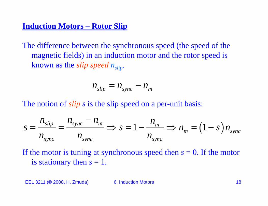
Induction Motors – Rotor Slip
The difference between the synchronous speed (the speed of the magnetic fields) in an induction motor and the rotor speed is known as the slip speed nknown as the slip speed nslip.
slip sync mn n n
The notion of slip s is the slip speed on a per-unit basis:
slip sync m
1 1slip sync m mm sync
sync sync sync
n n n ns s n s nn n n
If the motor is tuning at synchronous speed then s = 0. If the motor is stationary then s = 1.
y y y
EEL 3211 (© 2008, H. Zmuda) 6. Induction Motors 18
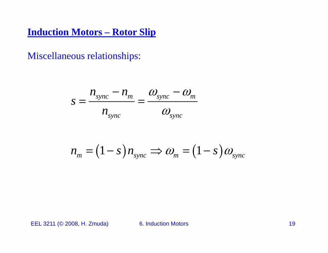
Induction Motors – Rotor Slip
Miscellaneous relationships:
sync m sync mn ns
n
sync syncn
1 1m sync m syncn s n s
EEL 3211 (© 2008, H. Zmuda) 6. Induction Motors 19
Electrical Frequency of the Rotor
The induction motor operates by inducing voltages and currents in the rotor and as such can be viewed as a rotating transformer.
The stator serves as the primary,
The rotor serves as the secondary,
BUT the secondary frequency is not necessarily the same as the U e seco da y eque cy s o ecessa y e sa e as eprimary frequency (unlike a transformer).
EEL 3211 (© 2008, H. Zmuda) 6. Induction Motors 20
Electrical Frequency of the Rotor
If the rotor is locked and cannot move, the frequency of the rotor current will be the same as that in the primary.
If the rotor turns at synchronous speed, the frequency of the rotor current will be zero.
What is the rotor frequency for any other speed of rotor rotation?
EEL 3211 (© 2008, H. Zmuda) 6. Induction Motors 21
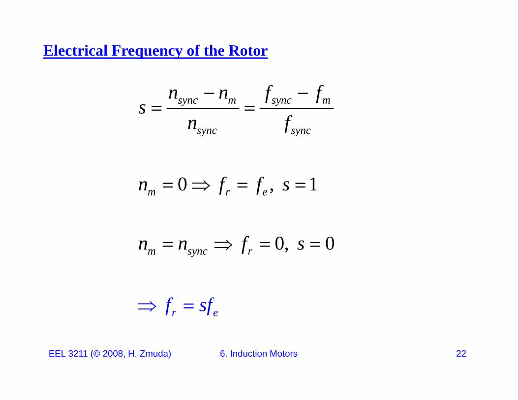
Electrical Frequency of the Rotor
sync m sync mn n f fs
n f
sync syncn f
0 , 1m r en f f s
0, 0m sync rn n f s
r eff s
EEL 3211 (© 2008, H. Zmuda) 6. Induction Motors 22
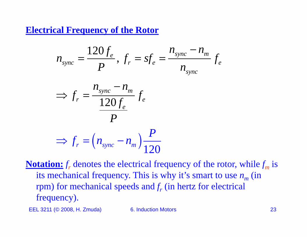
Electrical Frequency of the Rotor
120 , sync mesync r e e
sync
n nfn f sf fP n
1 02
sync
sync mr e
n nf ff
1 02 e
P
fP
Notation: f denotes the electrical frequency of the rotor while f is
1 02r sync m
Pf n n
Notation: fr denotes the electrical frequency of the rotor, while fm is its mechanical frequency. This is why it’s smart to use nm (in rpm) for mechanical speeds and fr (in hertz for electrical
EEL 3211 (© 2008, H. Zmuda) 6. Induction Motors 23
frequency).
Circuit Model (per Phase) for the Induction Motor
Because of the transformer-like operation, the model for the induction motor will be essentially that of the circuit model for a transformertransformer.
Because the induction motor is a single excited machine (no power applied to a field circuit), the model will not have an internally generated voltage EA as we had in the synchronous (doubly excited) machine.e c ed) ac e.
To develop the model for the induction motor, let’s start with the transformer model and go from theretransformer model and go from there.
EEL 3211 (© 2008, H. Zmuda) 6. Induction Motors 24

Circuit Model (per Phase) for the Induction Motor
Recall the transformer model from Note Set 3:
PjXPR SjXSR
PN SNCRMjX P SCRMjX
IDEAL
EEL 3211 (© 2008, H. Zmuda) 6. Induction Motors 25
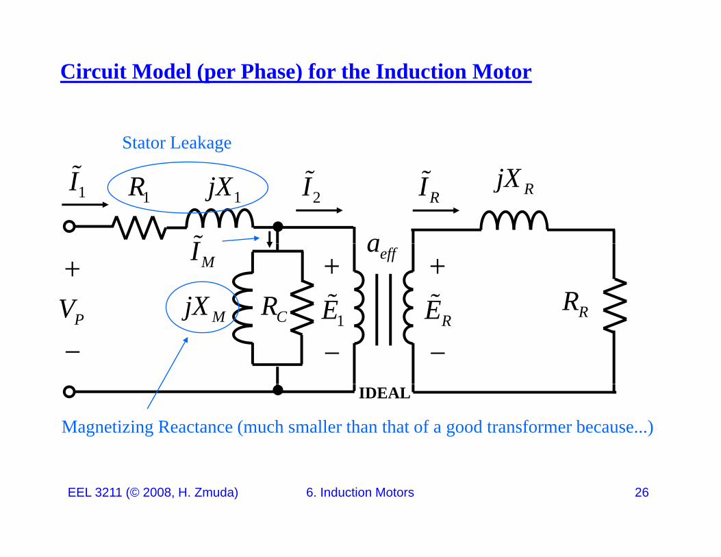
Circuit Model (per Phase) for the Induction Motor
jXI Stator Leakage
1jX1R RjX1I RI
I
2I
a
RRCRMjXV
EE
MI effa
RCRMjXPV
RE
1E
Magnetizing Reactance (much smaller than that of a good transformer because...)
IDEAL
EEL 3211 (© 2008, H. Zmuda) 6. Induction Motors 26
Circuit Model (per Phase) for the Induction Motor
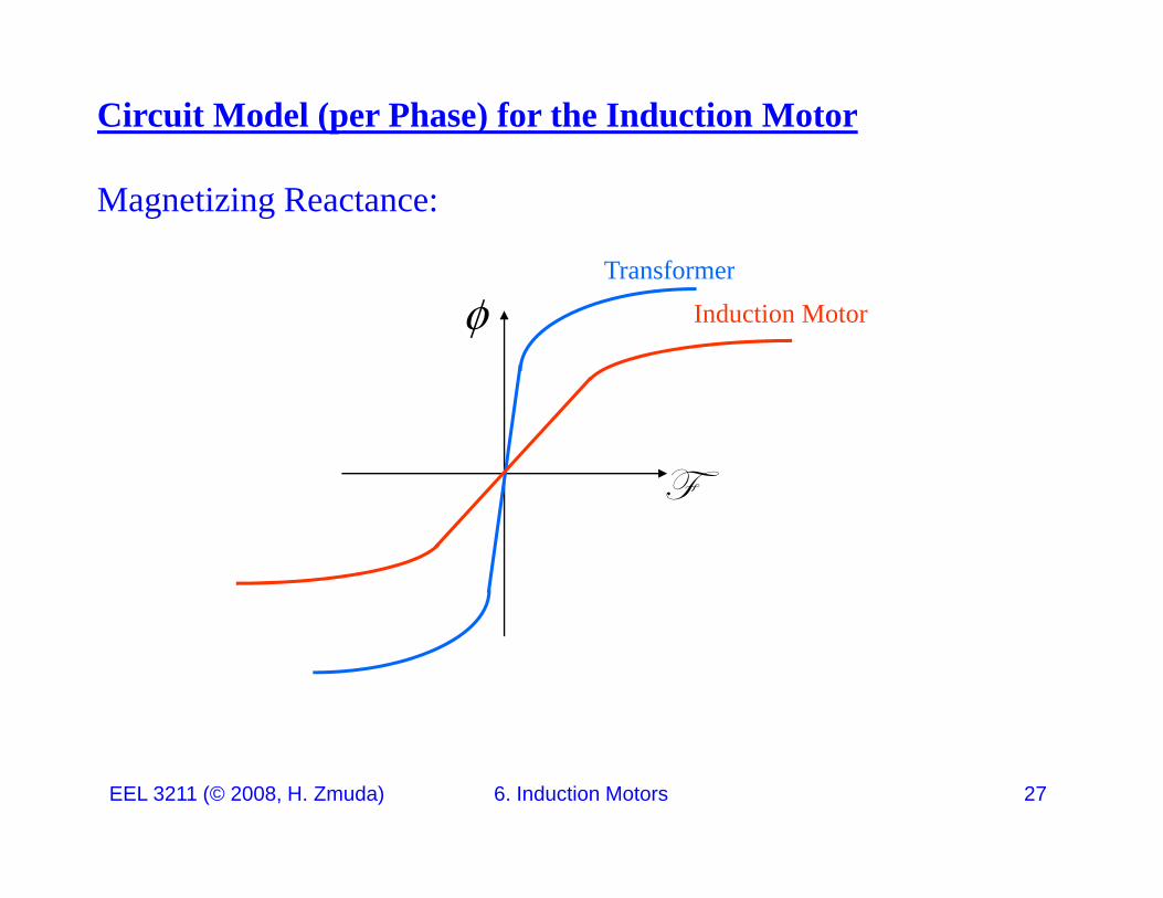
Magnetizing Reactance:
Transformer
Induction Motor
Y
EEL 3211 (© 2008, H. Zmuda) 6. Induction Motors 27
Circuit Model (per Phase) for the Induction Motor
Note how the slope of the motor’s flux-mmf curve is much shallower that that of a good transformer.
This is because of the presence of an air gap in the motor, not present in a transformer, which greatly increases the reluctance of the flux path and thereby reducing the coupling between primary and secondary.
The higher reluctance means that a higher magnetizing current is needed to obtain a given flux level.
This results in a much smaller value of XM than in an ordinary transformer.
EEL 3211 (© 2008, H. Zmuda) 6. Induction Motors 28
Circuit Model (per Phase) for the Induction Motor
The major difference between the model of the induction motor and that of a transformer is due the difference in frequency between th i d th dthe primary and the secondary.
How do we model this?
In general for an induction motor, a voltage is applied to the stator windings inducing a voltage in the rotor windings.windings inducing a voltage in the rotor windings.
The greater the relative motion between the rotor and stator magnetic field the greater the resulting rotor voltage and rotormagnetic field, the greater the resulting rotor voltage and rotor frequency, since
,i d lPe v B f n n
EEL 3211 (© 2008, H. Zmuda) 6. Induction Motors 29
,120ind rel r sync me v B f n n
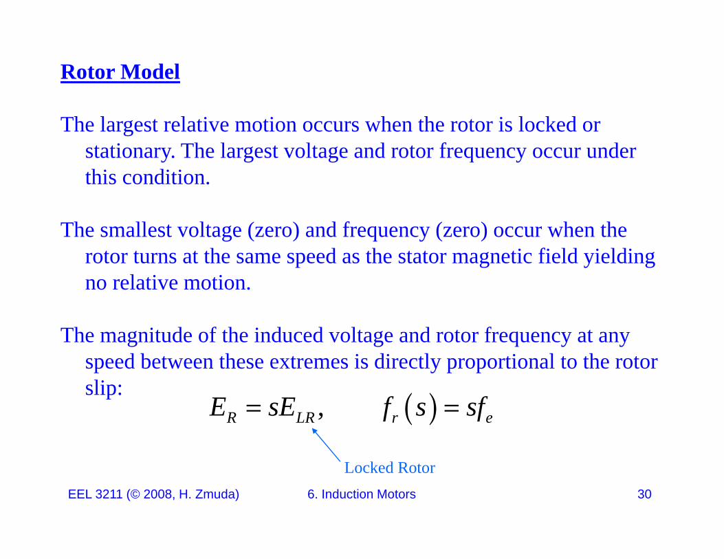
Rotor Model
The largest relative motion occurs when the rotor is locked or stationary. The largest voltage and rotor frequency occur under thi ditithis condition.
The smallest voltage (zero) and frequency (zero) occur when the rotor turns at the same speed as the stator magnetic field yielding no relative motion.
The magnitude of the induced voltage and rotor frequency at any speed between these extremes is directly proportional to the rotor slip:slip: ,R LR r eE sE f s sf
EEL 3211 (© 2008, H. Zmuda) 6. Induction Motors 30
Locked Rotor
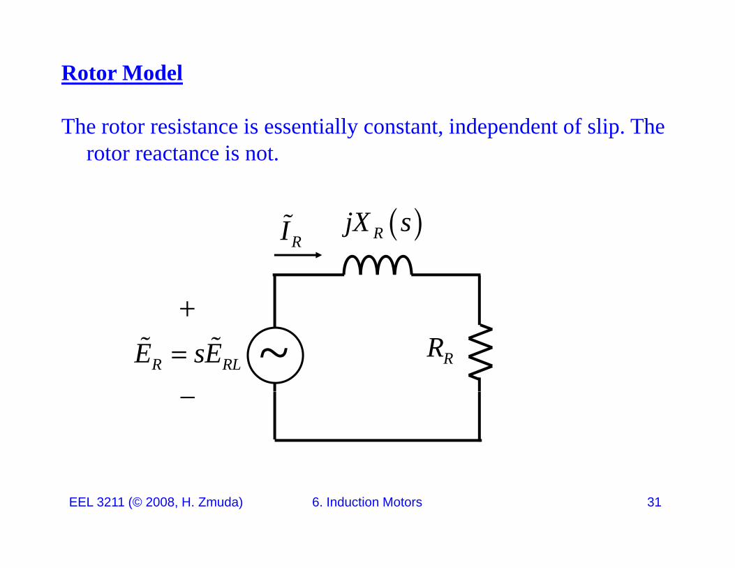
Rotor Model
The rotor resistance is essentially constant, independent of slip. The rotor reactance is not.
RjX sRI
RRR RLE sE ~
EEL 3211 (© 2008, H. Zmuda) 6. Induction Motors 31
Rotor Model
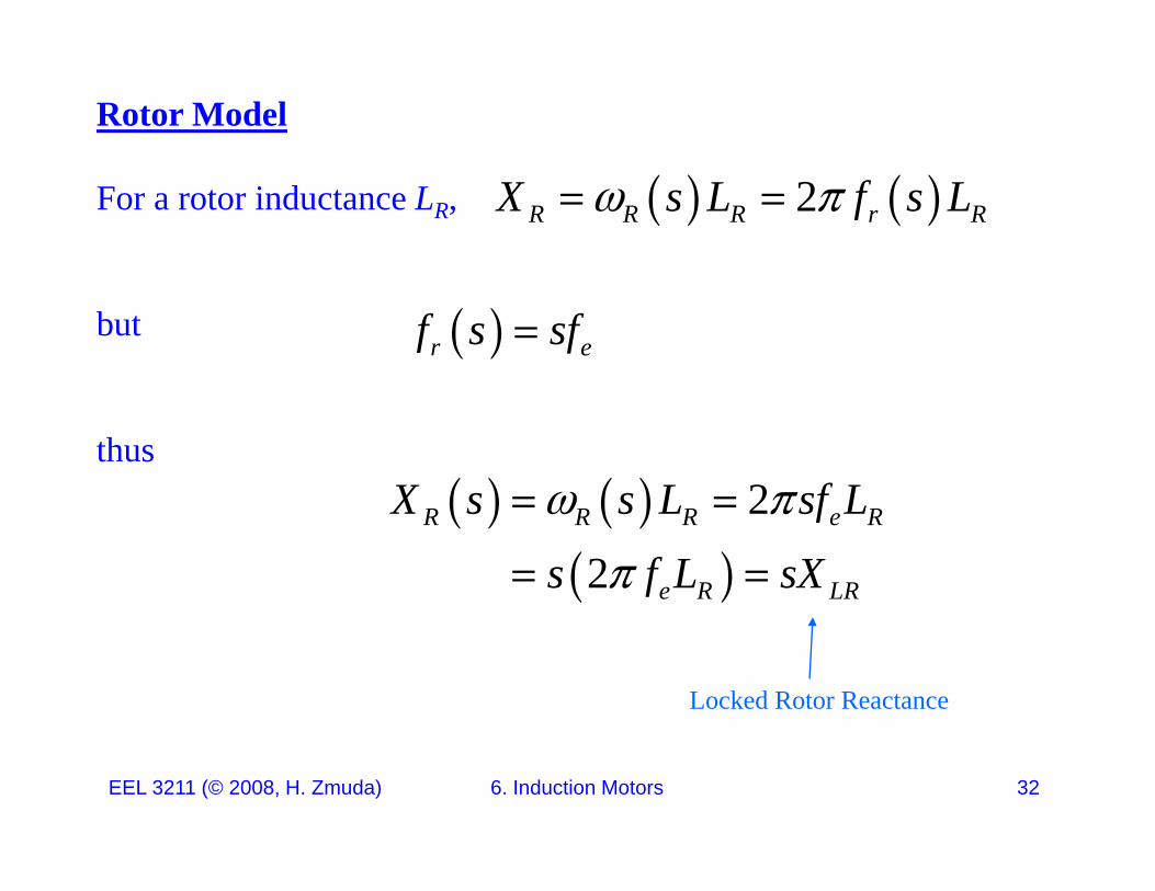
For a rotor inductance LR, 2R R R r RX s L f s L
but r ef s sf
thus 2X s s L sf L
2
2R R R e R
e R LR
X s s L sf L
s f L sX
Locked Rotor Reactance
EEL 3211 (© 2008, H. Zmuda) 6. Induction Motors 32
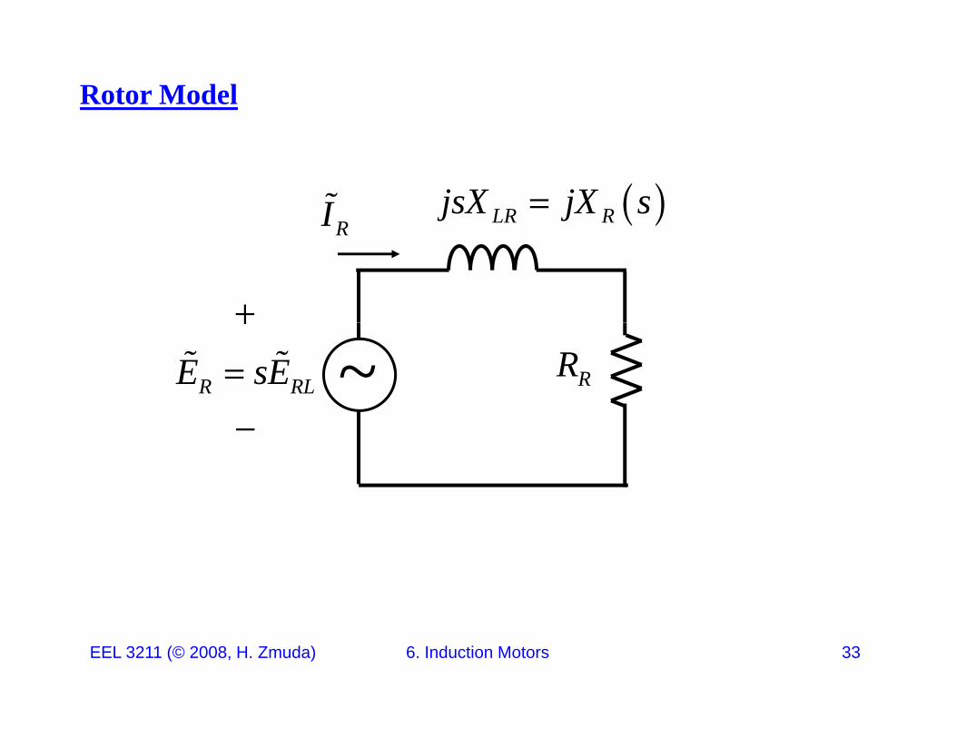
Rotor Model
LR RjsX jX sRI
R
RRR RLE sE
~
EEL 3211 (© 2008, H. Zmuda) 6. Induction Motors 33
Rotor Model
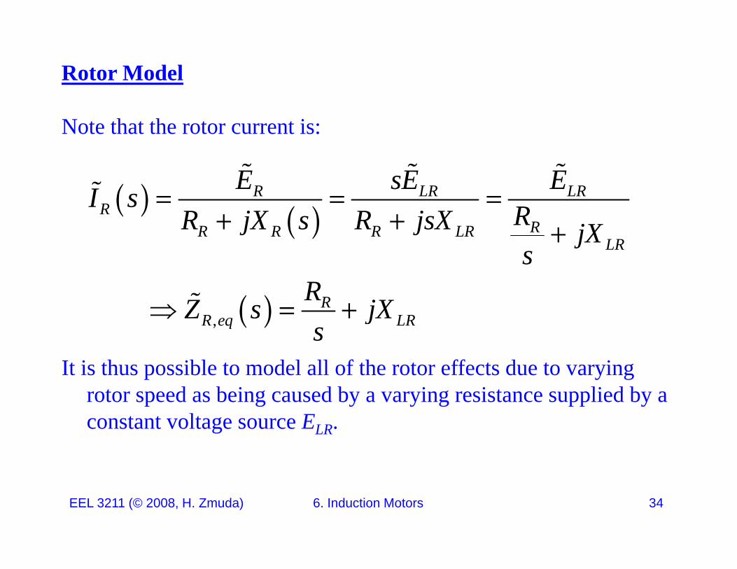
Note that the rotor current is:
E sE E
R LR LRR
RR R R LRLR
E sE EI s RR jX s R jsX jX
LR
RR eq LR
sRZ s jX
It is thus possible to model all of the rotor effects due to varying rotor speed as being caused by a varying resistance supplied by a
,R eq LRjs
rotor speed as being caused by a varying resistance supplied by a constant voltage source ELR.
EEL 3211 (© 2008, H. Zmuda) 6. Induction Motors 34
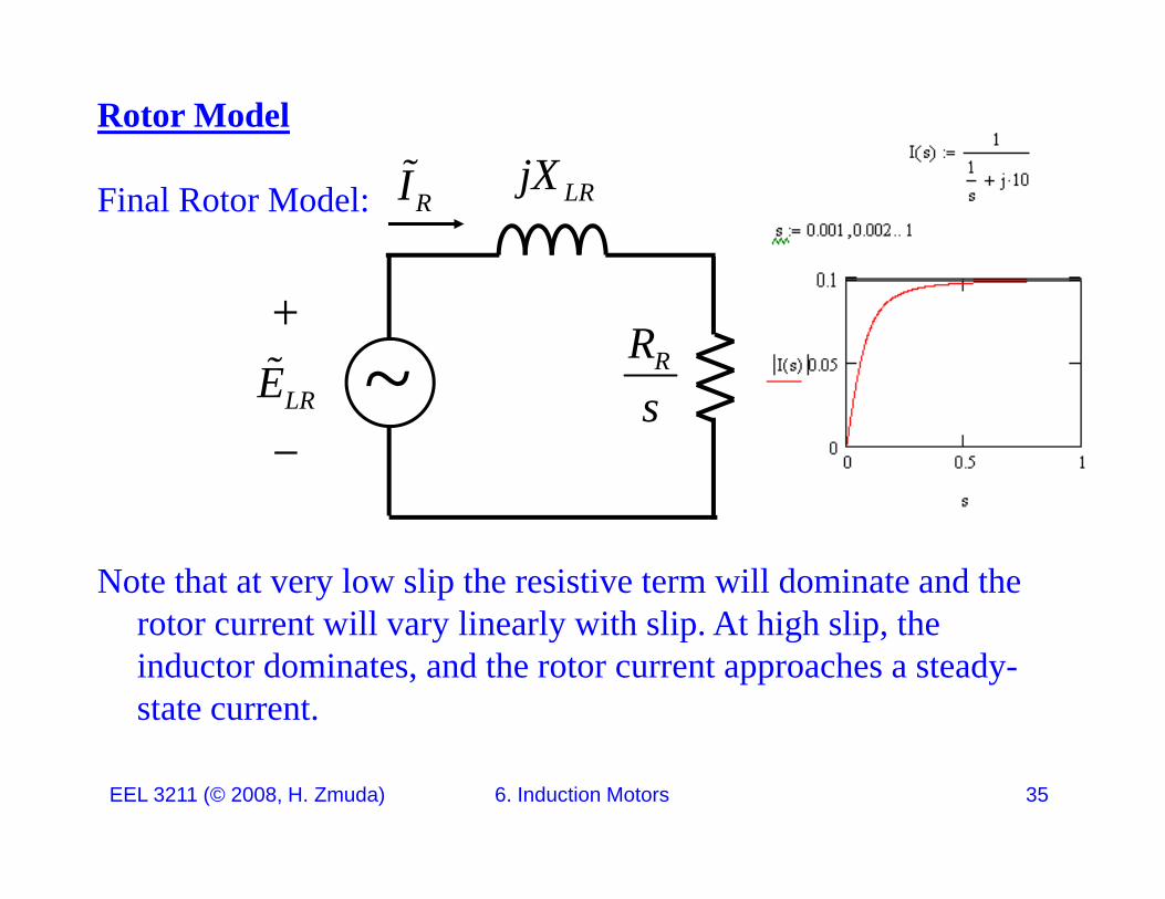
Rotor Model
jXFinal Rotor Model: LRjX
RI
RRLRE ~ sLRE
Note that at very low slip the resistive term will dominate and the rotor current will vary linearly with slip At high slip therotor current will vary linearly with slip. At high slip, the inductor dominates, and the rotor current approaches a steady-state current.
EEL 3211 (© 2008, H. Zmuda) 6. Induction Motors 35
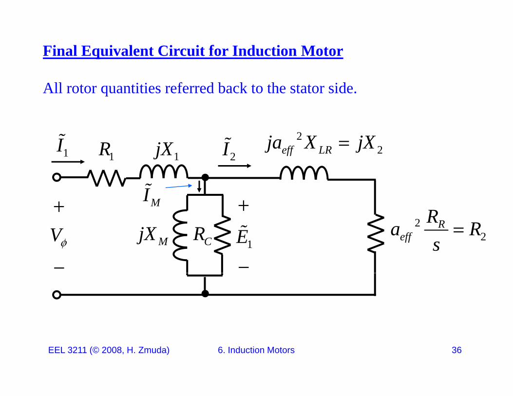
Final Equivalent Circuit for Induction Motor
All rotor quantities referred back to the stator side.
1jX1R2
2eff LRja X jX1I 2I
2 RR R MI
22
Reffa R
s
CRMjXV
1E
EEL 3211 (© 2008, H. Zmuda) 6. Induction Motors 36
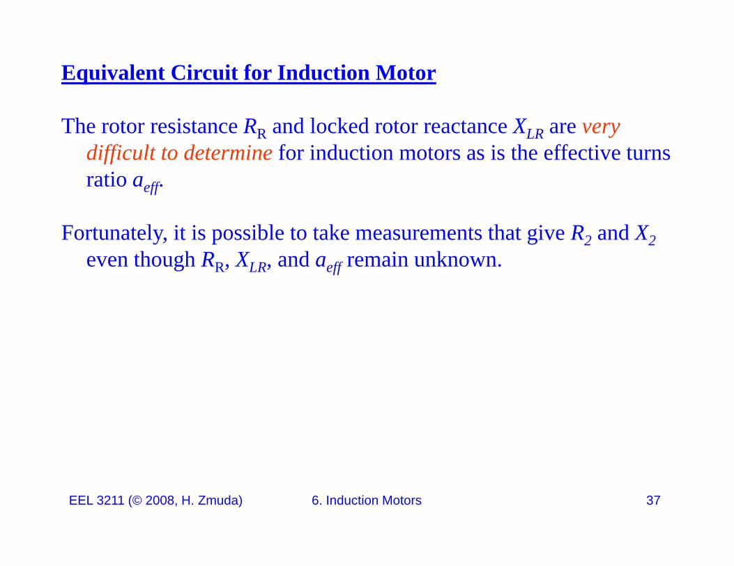
Equivalent Circuit for Induction Motor
The rotor resistance RR and locked rotor reactance XLR are verydifficult to determine for induction motors as is the effective turns
tiratio aeff.
Fortunately, it is possible to take measurements that give R2 and X2even though RR, XLR, and aeff remain unknown.
EEL 3211 (© 2008, H. Zmuda) 6. Induction Motors 37
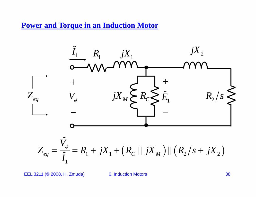
Power and Torque in an Induction Motor
1jX1R 2jX1I
2R sCRMjXV 1EeqZ
1 1 2 21
eq C M
VZ R jX R jX R s jX
I
EEL 3211 (© 2008, H. Zmuda) 6. Induction Motors 38
1I
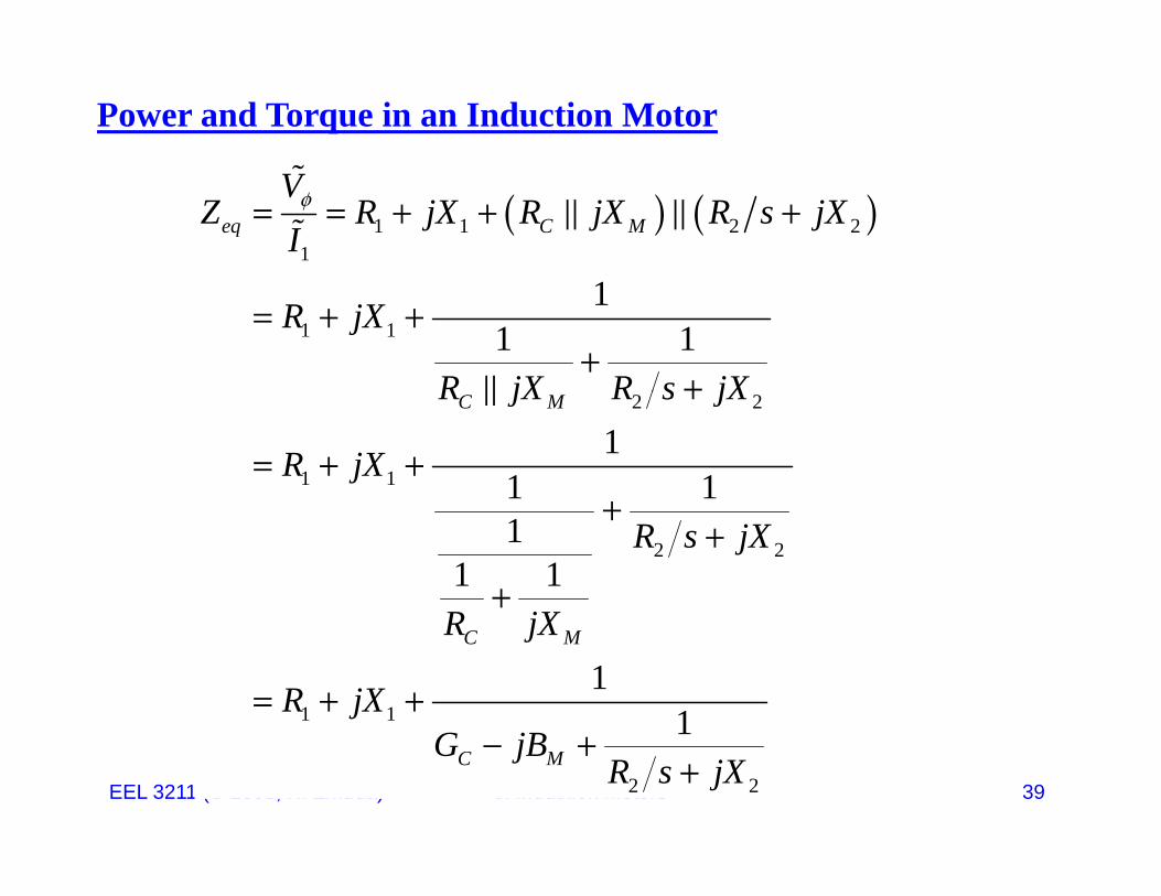
Power and Torque in an Induction Motor
1 1 2 2
1eq C M
VZ R jX R jX R s jX
I
1 11
1 1R jX
R jX R s jX
2 2
1 11
1 1
C MR jX R s jX
R jX
2 21
1 1R s jX
R jX
1 11
1
C MR jX
R jX
EEL 3211 (© 2008, H. Zmuda) 6. Induction Motors 392 2
1C MG jB
R s jX
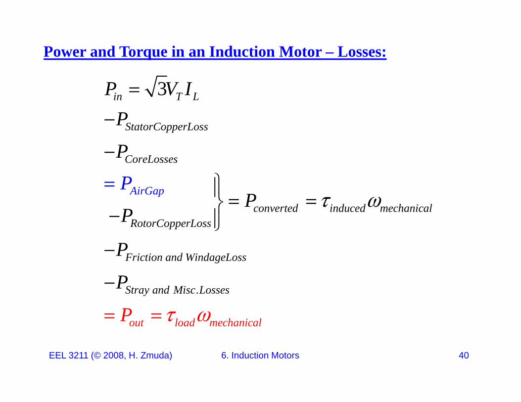
Power and Torque in an Induction Motor – Losses:
3in T L
St t C L
P V IP
StatorCopperLoss
CoreLosses
P
P
converted induced mechanical
RotorCopperLoss
AirGap PP
P
RotorCopperLoss
Friction and WindageLossP
P
.Stray and Mis
out load mechanic
c Losse
l
s
a
P
P
EEL 3211 (© 2008, H. Zmuda) 6. Induction Motors 40
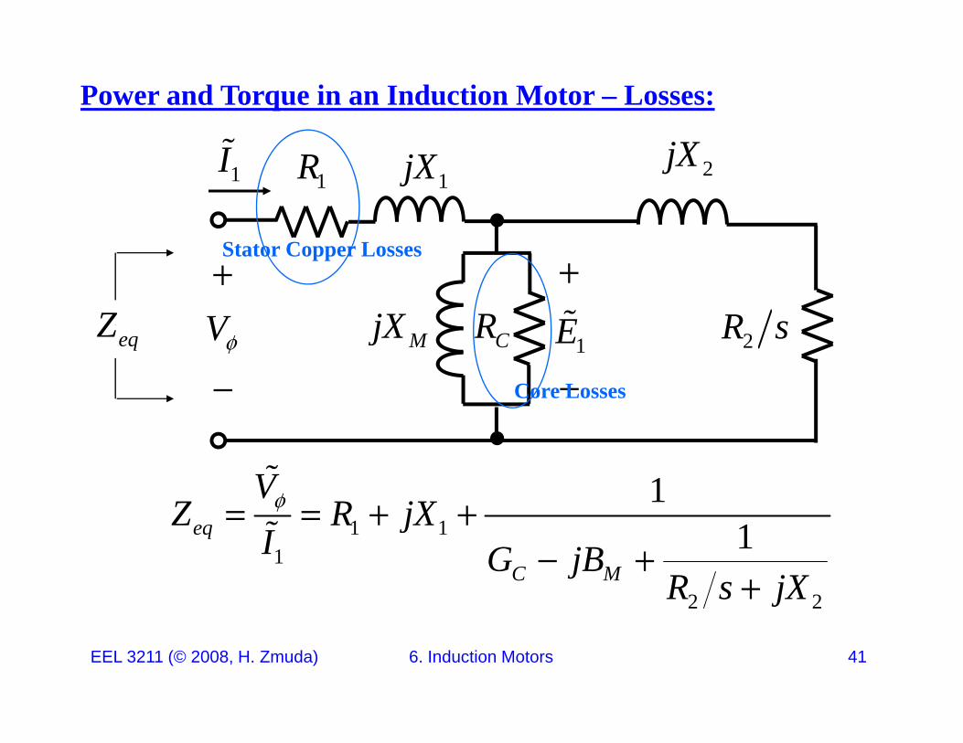
Power and Torque in an Induction Motor – Losses:
1jX1R 2jX1I
R sRjXV
EZ
Stator Copper Losses
2R sCRMjXV
1E
eqZ
Core Losses
1VZ R jX
1 1
1
2 2
1eq
C M
Z R jXI G jB
R s jX
EEL 3211 (© 2008, H. Zmuda) 6. Induction Motors 41
2 2j
Power and Torque in an Induction Motor – Losses:
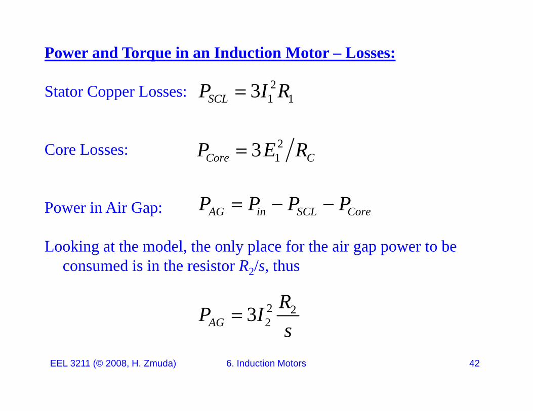
Stator Copper Losses: 21 13SCLP I R
Core Losses: 213Core CP E R
Power in Air Gap: AG in SCL CoreP P P P
Looking at the model, the only place for the air gap power to be consumed is in the resistor R2/s, thus
2 223AG
RP Is
EEL 3211 (© 2008, H. Zmuda) 6. Induction Motors 42
s
Power and Torque in an Induction Motor – Losses:
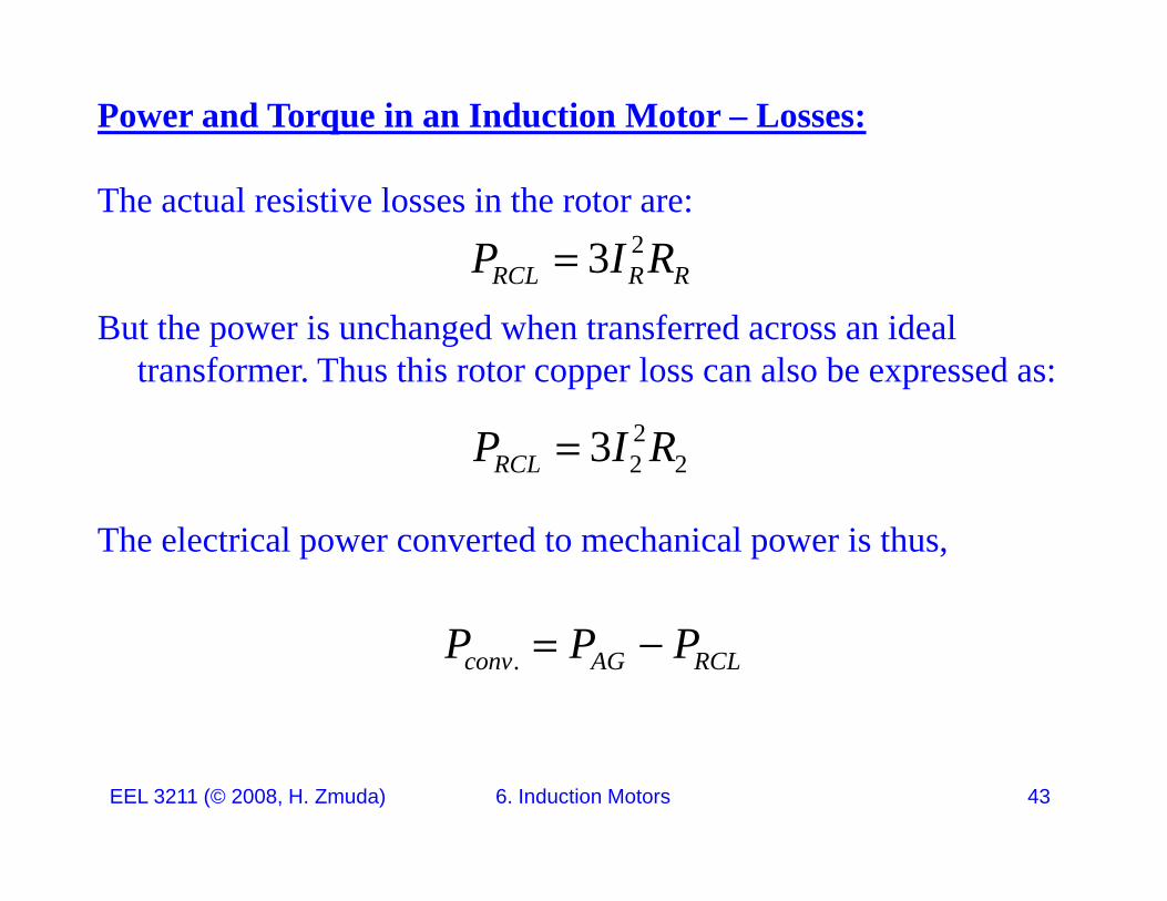
The actual resistive losses in the rotor are:23RCL R RP I R
But the power is unchanged when transferred across an ideal transformer. Thus this rotor copper loss can also be expressed as:
RCL R R
22 23RCLP I R
The electrical power converted to mechanical power is thus,
.conv AG RCLP P P
EEL 3211 (© 2008, H. Zmuda) 6. Induction Motors 43
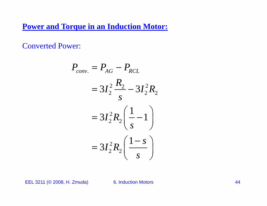
Power and Torque in an Induction Motor:
Converted Power:
P P P.
2 223 3
conv AG RCLP P PRI I R
2 2 2
2
3 3
13 1
I I Rs
I R
2 2
2
3 1
1
I Rs
s
22 2
13 sI Rs
EEL 3211 (© 2008, H. Zmuda) 6. Induction Motors 44
Power and Torque in an Induction Motor:
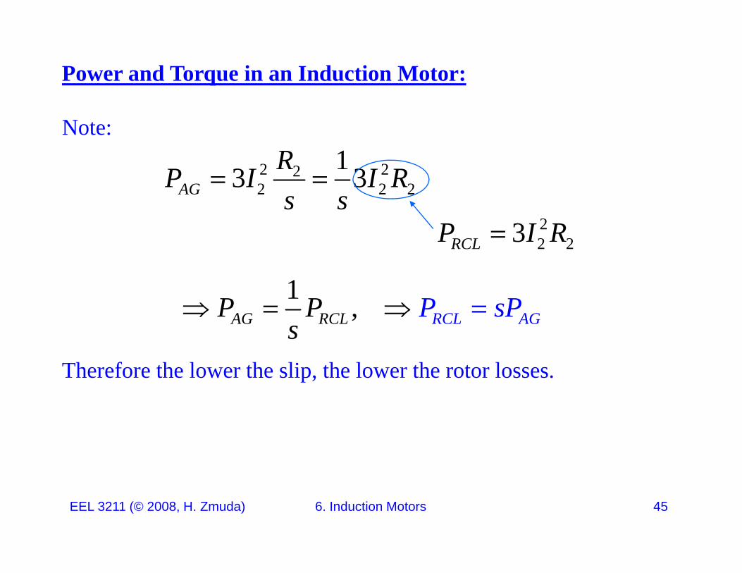
Note:
2 22 13 3RP I I R 2 2 23 3AGP I I Rs s
22 23RCLP I R
1 ,AG RCL RCL AGP sPP P
Therefore the lower the slip, the lower the rotor losses.
AG RCL RCL AGs
EEL 3211 (© 2008, H. Zmuda) 6. Induction Motors 45
Power and Torque in an Induction Motor:
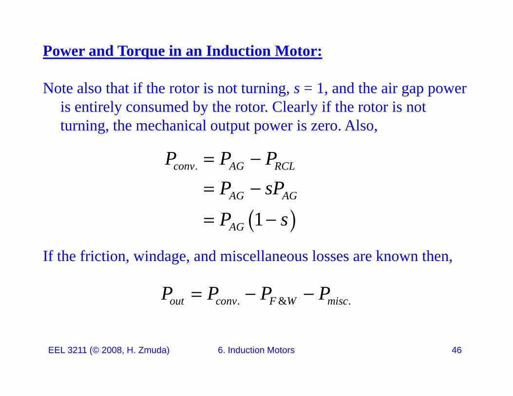
Note also that if the rotor is not turning, s = 1, and the air gap power is entirely consumed by the rotor. Clearly if the rotor is not t i th h i l t t i Alturning, the mechanical output power is zero. Also,
.conv AG RCLP P P
1AG AG
AG
P sPP s
If the friction, windage, and miscellaneous losses are known then,
1AGP s
. & .out conv F W miscP P P P
EEL 3211 (© 2008, H. Zmuda) 6. Induction Motors 46
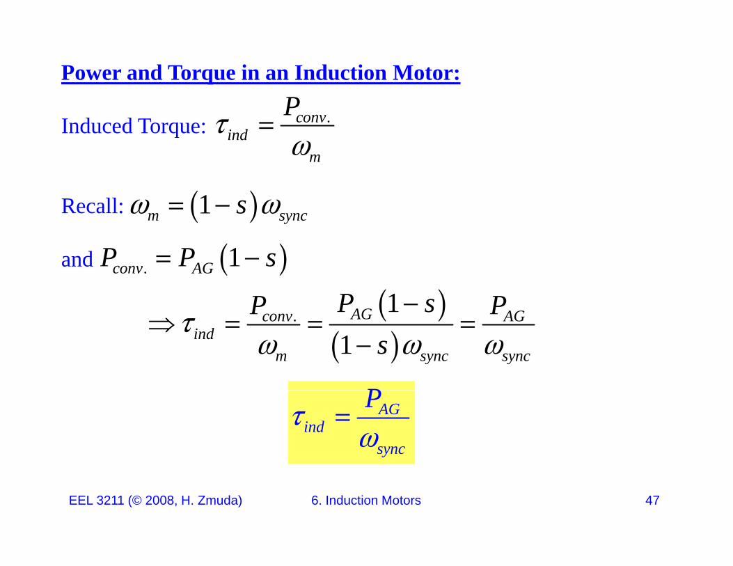
Power and Torque in an Induction Motor:P
Induced Torque: .convind
m
P
Recall: 1m syncs
and . 1conv AGP P s
1AGconv AGP sP P
.
1AGconv AG
indm sync syncs
PAGind
sync
P
EEL 3211 (© 2008, H. Zmuda) 6. Induction Motors 47
Power and Torque in an Induction Motor:
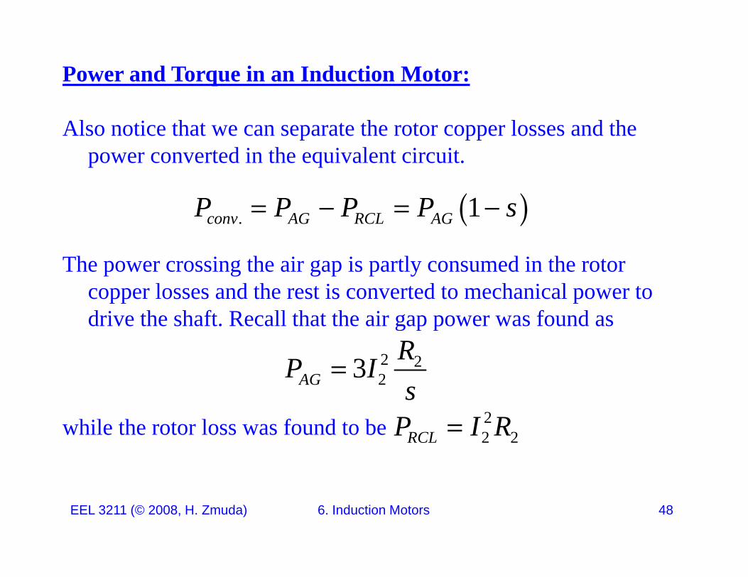
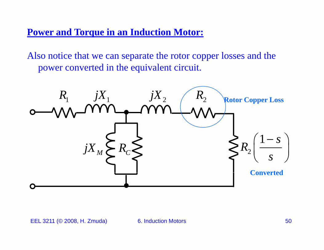
Also notice that we can separate the rotor copper losses and the power converted in the equivalent circuit.
. 1conv AG RCL AGP P P P s
The power crossing the air gap is partly consumed in the rotor copper losses and the rest is converted to mechanical power to drive the shaft. Recall that the air gap power was found asdrive the shaft. Recall that the air gap power was found as
2 223AG
RP Is
while the rotor loss was found to bes
22 2RCLP I R
EEL 3211 (© 2008, H. Zmuda) 6. Induction Motors 48
Power and Torque in an Induction Motor:
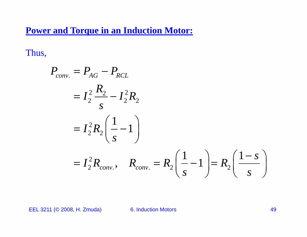
Thus,
AG RCLP P P .
2 222 2 2
conv AG RCLP P PRI I R
22 2
1 1
s
I R
2 2
2 1 11
ssI R R R R
2 . . 2 2, 1conv convI R R R Rs s
EEL 3211 (© 2008, H. Zmuda) 6. Induction Motors 49
Power and Torque in an Induction Motor:
Also notice that we can separate the rotor copper losses and the power converted in the equivalent circuit.
1jX1R 2jX 2R Rotor Copper Loss
1 s CRMjX 2
1 sRs
ConvertedConverted
EEL 3211 (© 2008, H. Zmuda) 6. Induction Motors 50

Torque-Speed Characteristics of an Induction Motor:
How does the torque of an induction motor change as the load changes?
How much torque can an induction motor supply at starting conditions?
Hw much does the speed of an induction motor shaft drop as the load increases?load increases?
All these questions can be answered with our circuit model.
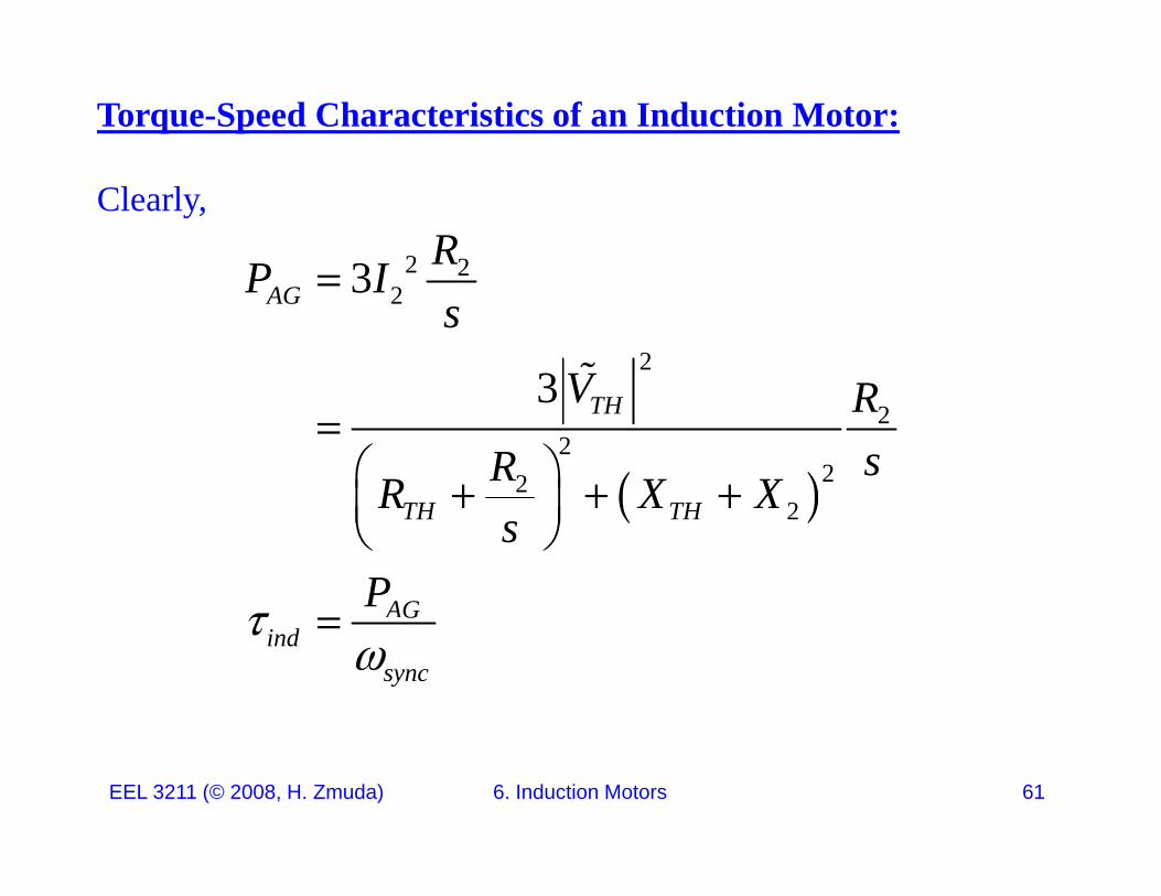
Recall two important results: .conv AGind
m sync
P P
EEL 3211 (© 2008, H. Zmuda) 6. Induction Motors 51
m sync
Torque-Speed Characteristics of an Induction Motor:
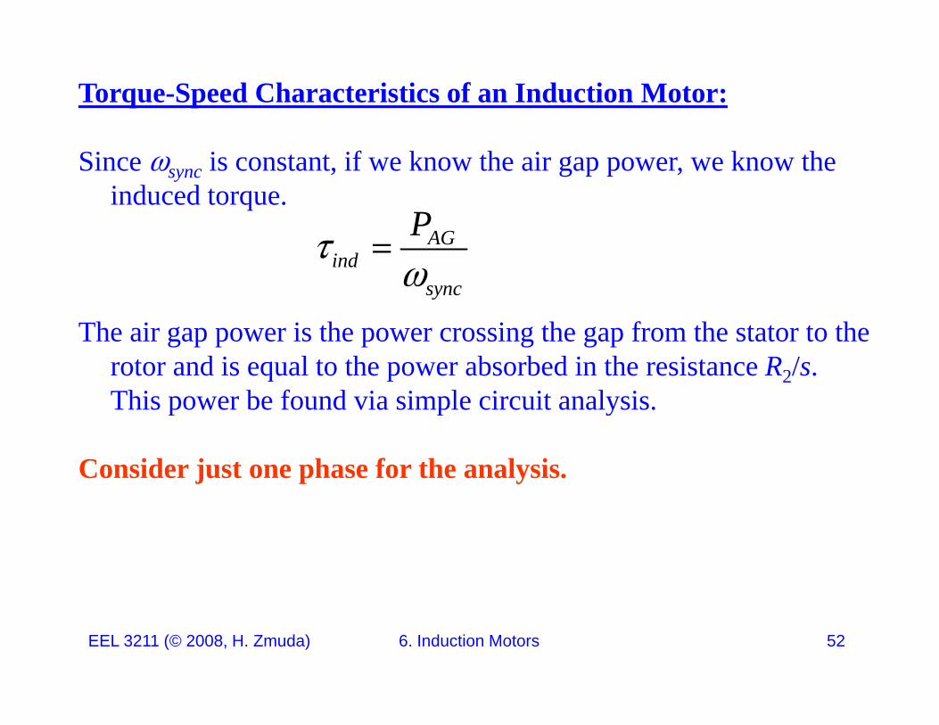
Since sync is constant, if we know the air gap power, we know the induced torque.
PAGind
sync
P
The air gap power is the power crossing the gap from the stator to the rotor and is equal to the power absorbed in the resistance R2/s. This power be found via simple circuit analysis.This power be found via simple circuit analysis.
Consider just one phase for the analysis.
EEL 3211 (© 2008, H. Zmuda) 6. Induction Motors 52

Torque-Speed Characteristics of an Induction Motor:
Compute the Thevenin Equivalent Circuit at the place shown below.
1jX1R 2jX1I
2I
RRjXV
E Z
2R sCRMjXV
1E
THZ
22 2AGP I R s
EEL 3211 (© 2008, H. Zmuda) 6. Induction Motors 53
Torque-Speed Characteristics of an Induction Motor:
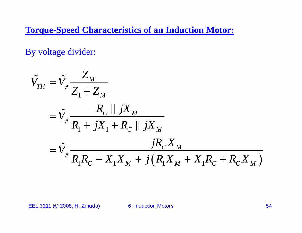
By voltage divider:
Z
1
MTH
M
ZV VZ Z
1 1
C M
C M
R jXVR jX R jX
1 1 C M
C MjR XVR R X X j R X X R R X
1 1 1 1C M M C C MR R X X j R X X R R X
EEL 3211 (© 2008, H. Zmuda) 6. Induction Motors 54
Torque-Speed Characteristics of an Induction Motor:
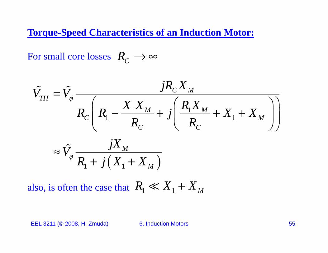
For small core losses CR
1 1
C MTH
M M
jR XV VX X R XR R j X X
1 1
1 1M M
C MC C
R R j X XR R
jX
1 1
M
M
jXVR j X X
also, is often the case that 1 1 MR X X
EEL 3211 (© 2008, H. Zmuda) 6. Induction Motors 55
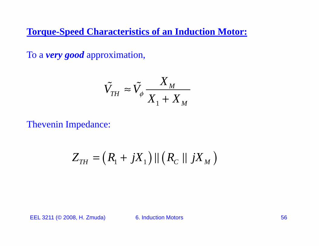
Torque-Speed Characteristics of an Induction Motor:
To a very good approximation,
1
MTH
M
XV VX X
Thevenin Impedance:
1 1TH C MZ R jX R jX
EEL 3211 (© 2008, H. Zmuda) 6. Induction Motors 56
Torque-Speed Characteristics of an Induction Motor:
1 1C M
C M
jR XR jXR jX
Z
1 1
C MTH
C M
C M
jZ jR XR jX
R jX
1 1
C M
C M
R jXjR X R jX
R R X X j R X R X R X
1 1 1 1
1 1
C M C M C M
C M
R R X X j R X R X R X
jR X R jX
1 1
1 1M M
C MX X R XR R j X X
R R
EEL 3211 (© 2008, H. Zmuda) 6. Induction Motors 57
C CR R
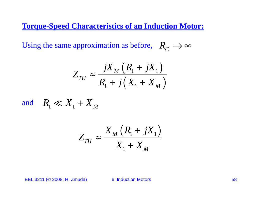
Torque-Speed Characteristics of an Induction Motor:
Using the same approximation as before,
CR
1 1
1 1
MTH
M
jX R jXZ
R j X X
and
1 1 MR X X
1 1MTH
X R jXZ
1TH
M
ZX X
EEL 3211 (© 2008, H. Zmuda) 6. Induction Motors 58
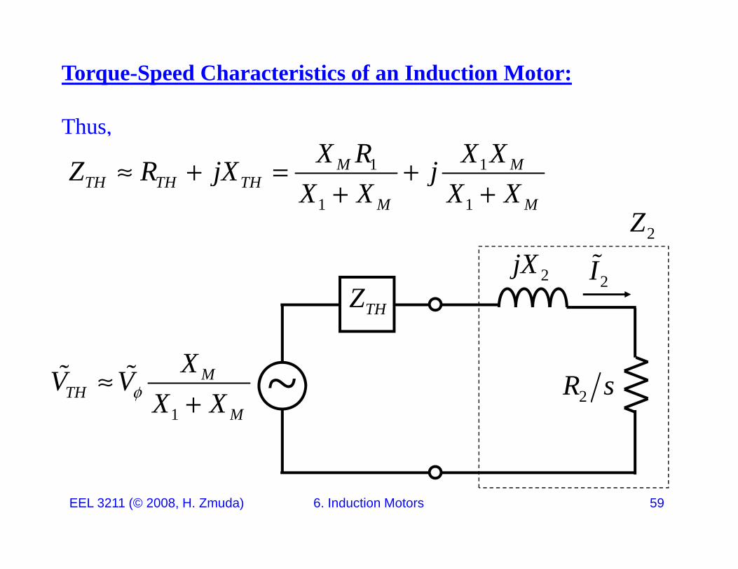
Torque-Speed Characteristics of an Induction Motor:
Thus,1 1M M
TH TH THX R X XZ R jX j 1 1
TH TH THM M
Z R jX jX X X X
2Z
2jX2I
THZ
2R s~MTH
XV V 2R s
1TH
MX X
EEL 3211 (© 2008, H. Zmuda) 6. Induction Motors 59
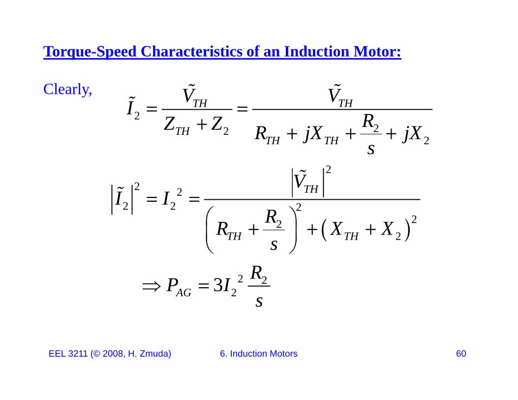
Torque-Speed Characteristics of an Induction Motor:
Clearly,2
2
TH THV VI RZ Z
22
2
2
THTH TH
RZ Z R jX jXs
V
2 22 2 2
22
THVI I
RR X X
22
2
TH THR X Xs
R
2 223AG
RP Is
EEL 3211 (© 2008, H. Zmuda) 6. Induction Motors 60
Torque-Speed Characteristics of an Induction Motor:
Clearly,
2 23 RP I 2
2
3
3
AGP Is
V R
2
222
2
3 TH
TH TH
V RsRR X X
2TH TH
AG
R X Xs
P
Gind
sync
EEL 3211 (© 2008, H. Zmuda) 6. Induction Motors 61

Torque-Speed Characteristics of an Induction Motor:
Plot ind vs. nm. Use:
2
22
3 THind
V RsR
222
syncTH TH
sRR X Xs
120r sync mPf n n
1 1m sync m syncn s n s
EEL 3211 (© 2008, H. Zmuda) 6. Induction Motors 62
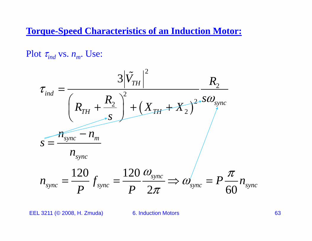
Torque-Speed Characteristics of an Induction Motor:
Plot ind vs. nm. Use:
23 V
2
222
3 THind
sync
V RsRR X X
2
2y
TH THR X Xs
n n
sync m
sync
n ns
n
120 1202 60
syncsync sync sync syncn f P n
P P
EEL 3211 (© 2008, H. Zmuda) 6. Induction Motors 63
Torque-Speed Characteristics of an Induction Motor:
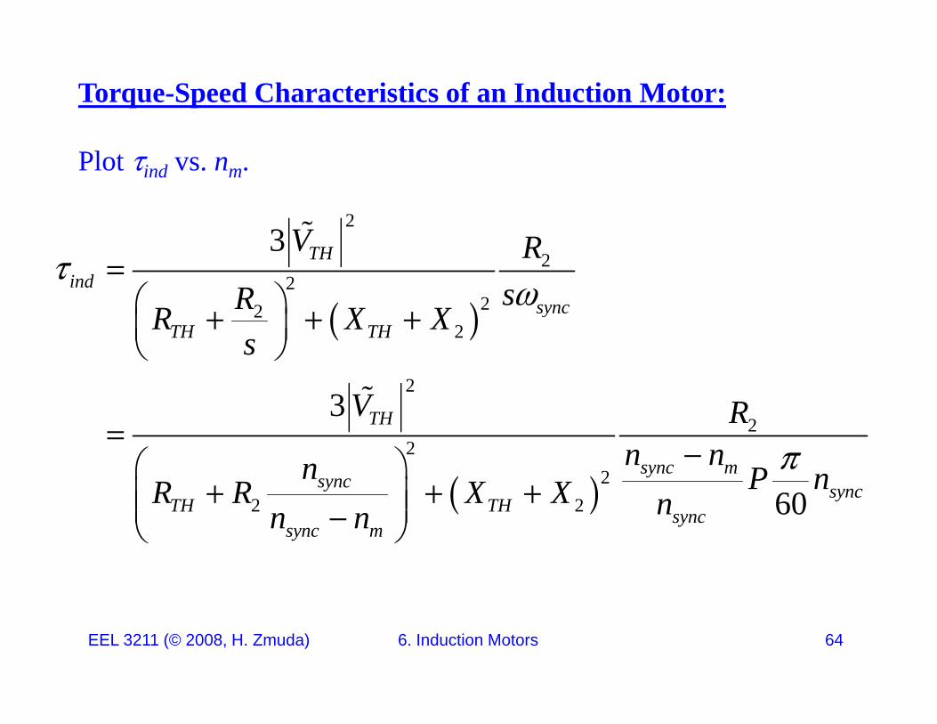
Plot ind vs. nm.
2
2
22
22
3 THind
sync
V RsRR X X
2
2
23
yTH THR X X
s
V R
22
22 2
3
60
TH
sync msync sync
TH TH
V Rn nn P nR R X X
2 2 60 yTH TH sync
sync m
R R X X nn n
EEL 3211 (© 2008, H. Zmuda) 6. Induction Motors 64
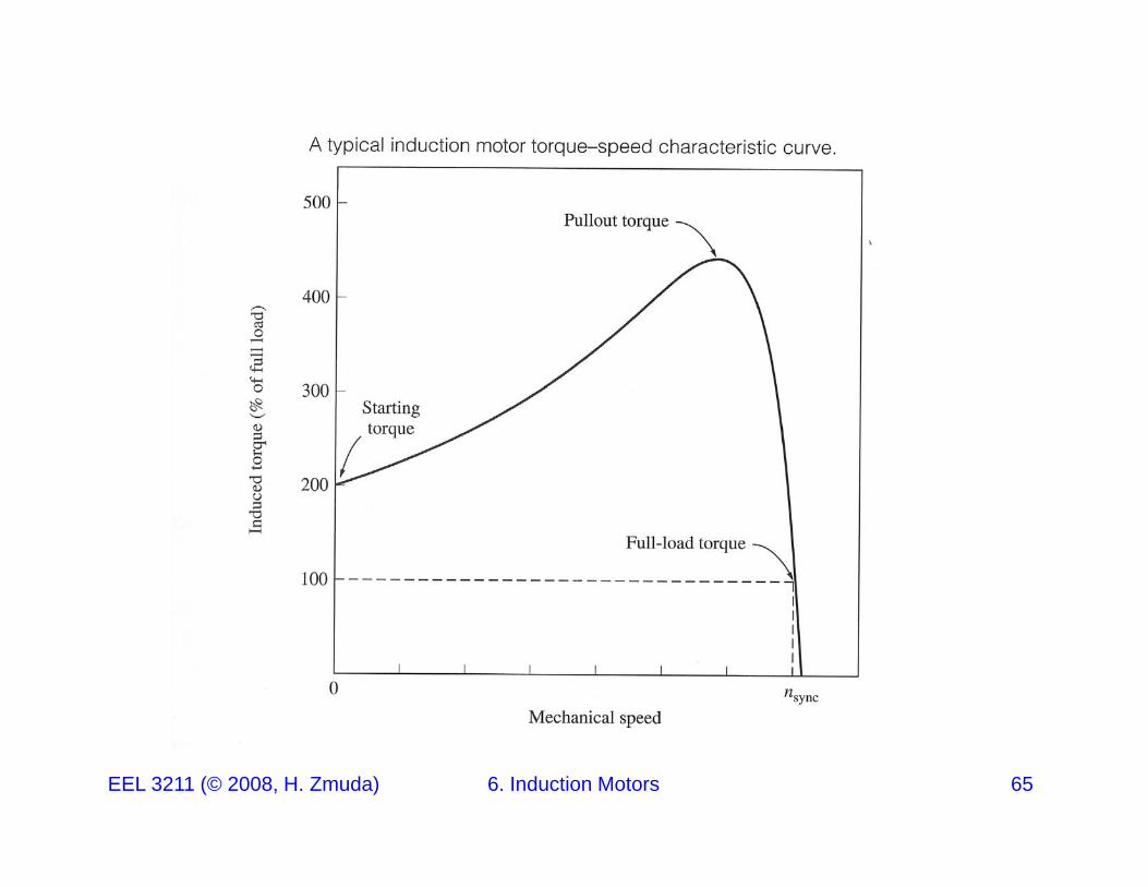
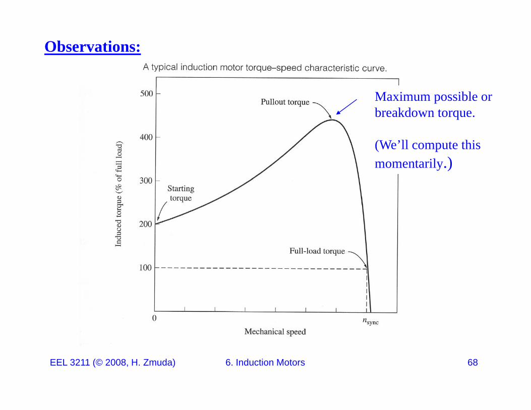
EEL 3211 (© 2008, H. Zmuda) 6. Induction Motors 65
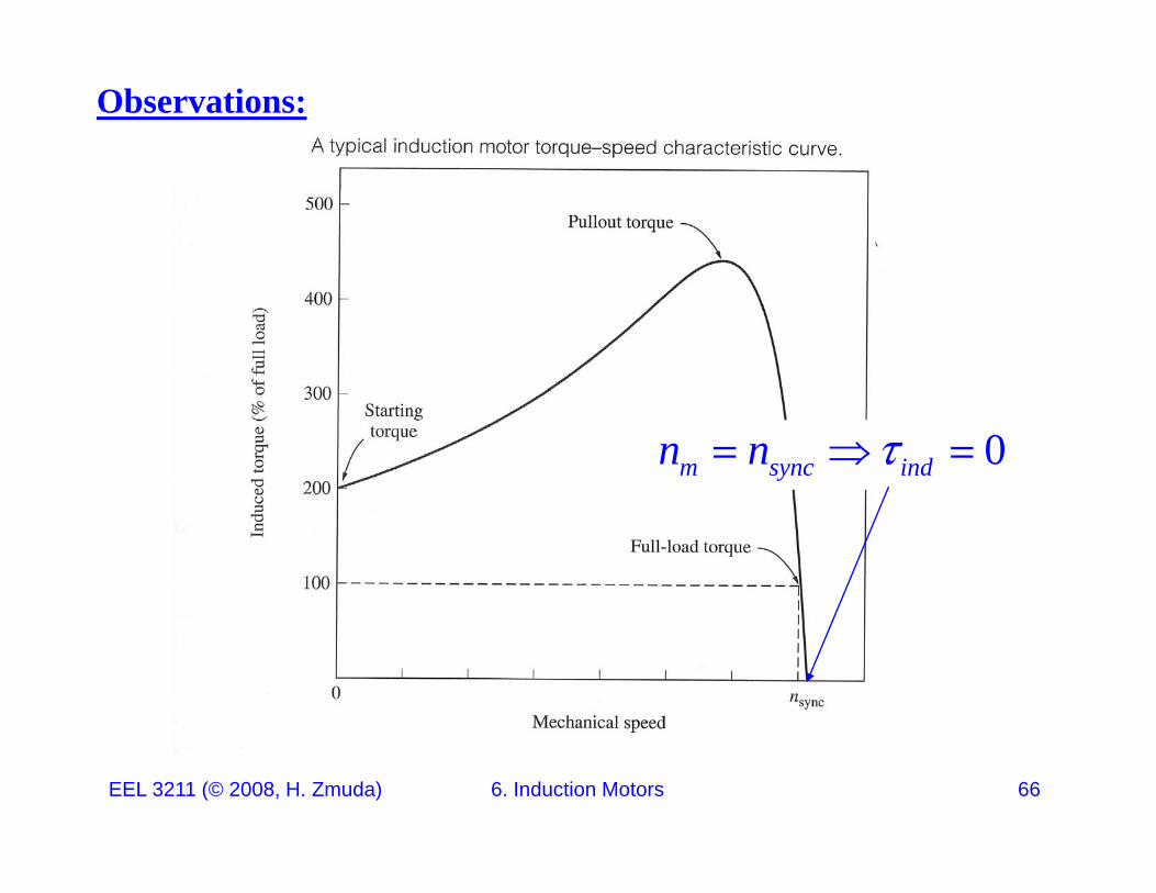
Observations:
0m sync indn n
EEL 3211 (© 2008, H. Zmuda) 6. Induction Motors 66
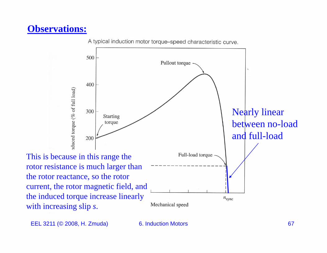
Observations:
Nearl linearNearly linearbetween no-loadand full-load
This is because in this range the rotor resistance is much larger than th t t th tthe rotor reactance, so the rotor current, the rotor magnetic field, and the induced torque increase linearly with increasing slip s
EEL 3211 (© 2008, H. Zmuda) 6. Induction Motors 67
with increasing slip s.
Observations:
Maximum possible orbreakdown torque.
(We’ll compute thismomentarily.)
EEL 3211 (© 2008, H. Zmuda) 6. Induction Motors 68
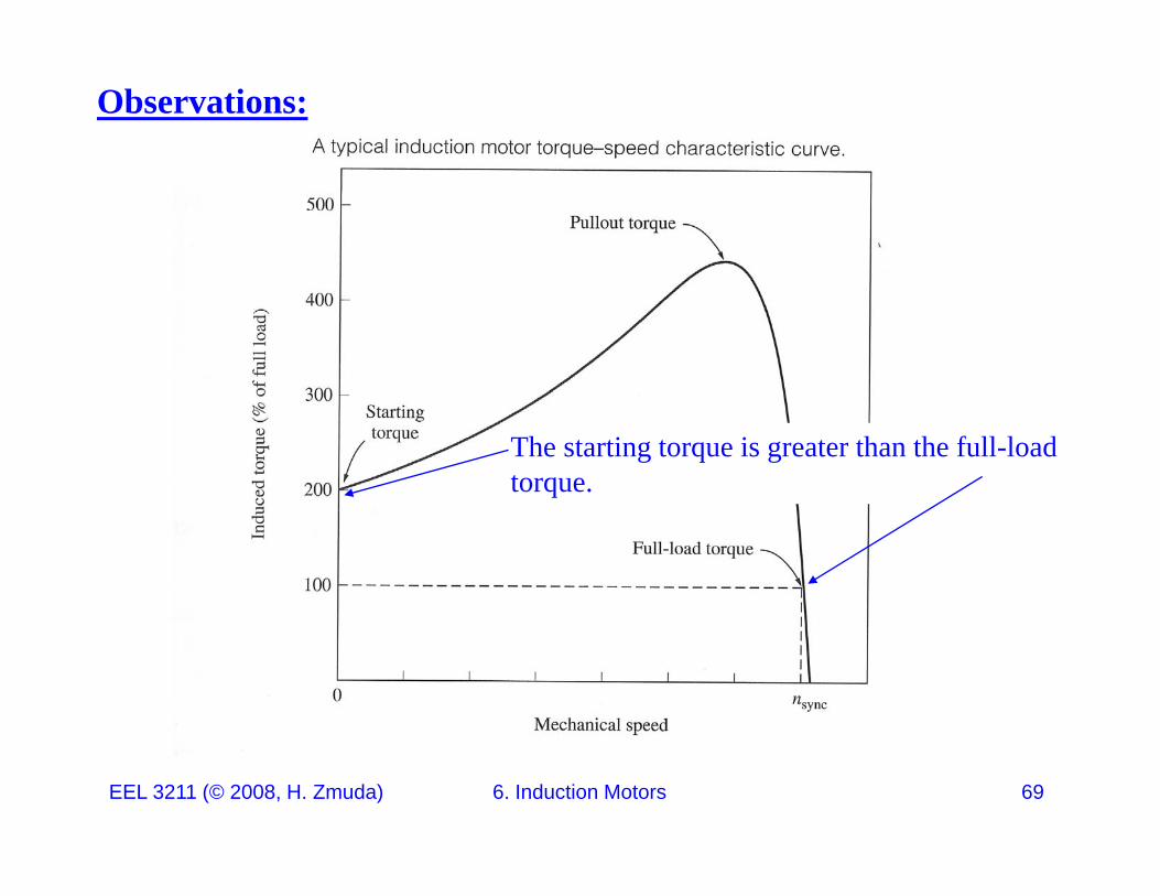
Observations:
The starting torque is greater than the full-load torque.
EEL 3211 (© 2008, H. Zmuda) 6. Induction Motors 69
Observations:
Since2 2
ind THV V
The torque for a given slip varies as the square of the applied voltage.
ind TH
This is an important observation for one form of motor speed control to be discussed later.
EEL 3211 (© 2008, H. Zmuda) 6. Induction Motors 70
Observations:
If the rotor is driven faster then synchronous speed, the direction of the induced torque reverses and the machine becomes a generator.
If the motor is turning backwards relative to the direction of the stator magnetic fields, the motor will stop very rapidly and try to t i th th di titurn in the other direction.
Recall that reversing the direction of magnetic field rotation is simply a matter of switching any two stator phases.
This method is used to rapidly stop an induction motor and is calledThis method is used to rapidly stop an induction motor and is called plugging.
EEL 3211 (© 2008, H. Zmuda) 6. Induction Motors 71
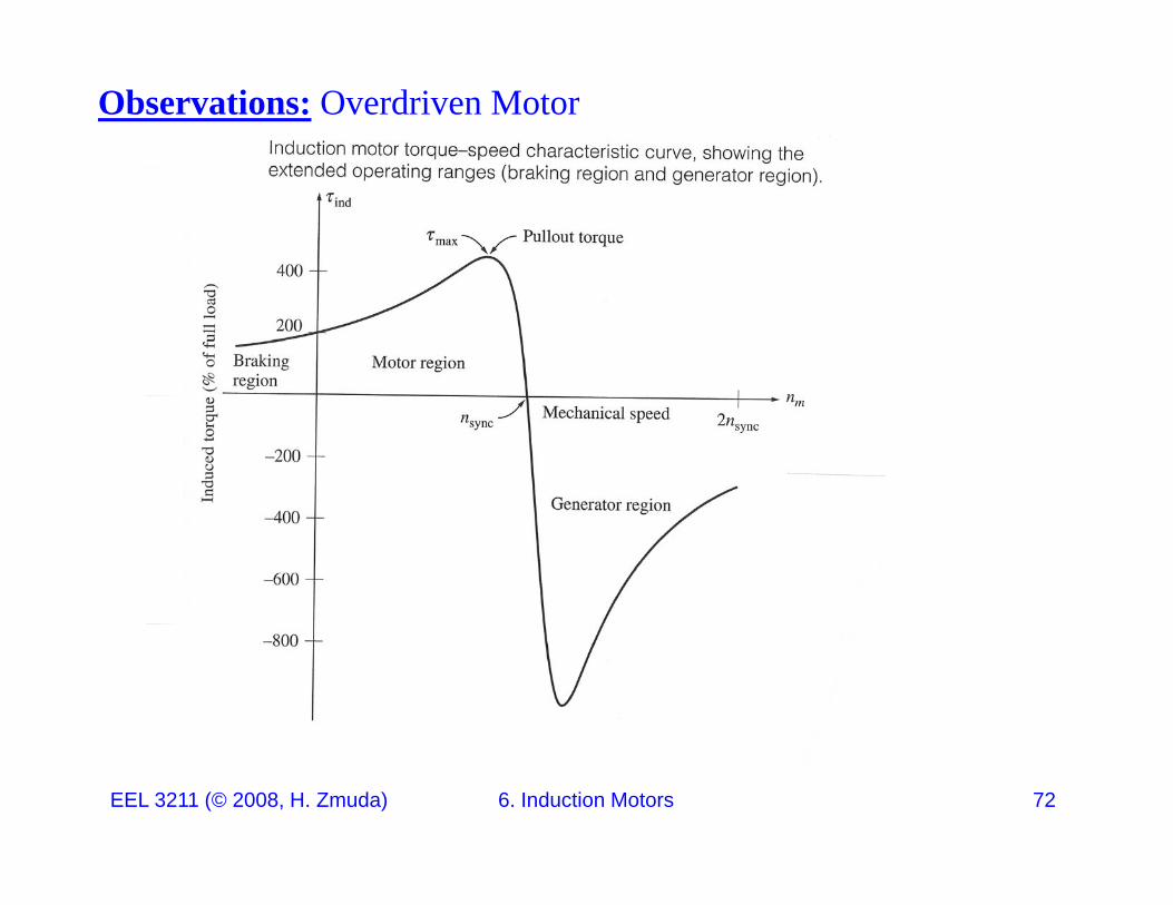
Observations: Overdriven Motor
EEL 3211 (© 2008, H. Zmuda) 6. Induction Motors 72
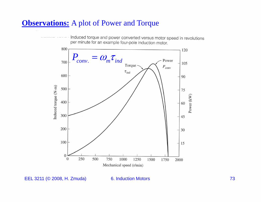
Observations: A plot of Power and Torque
.conv m indP
EEL 3211 (© 2008, H. Zmuda) 6. Induction Motors 73
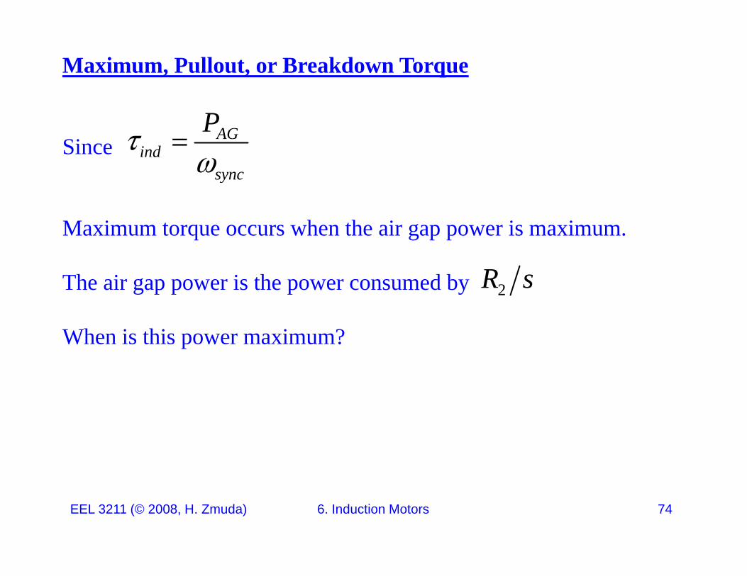
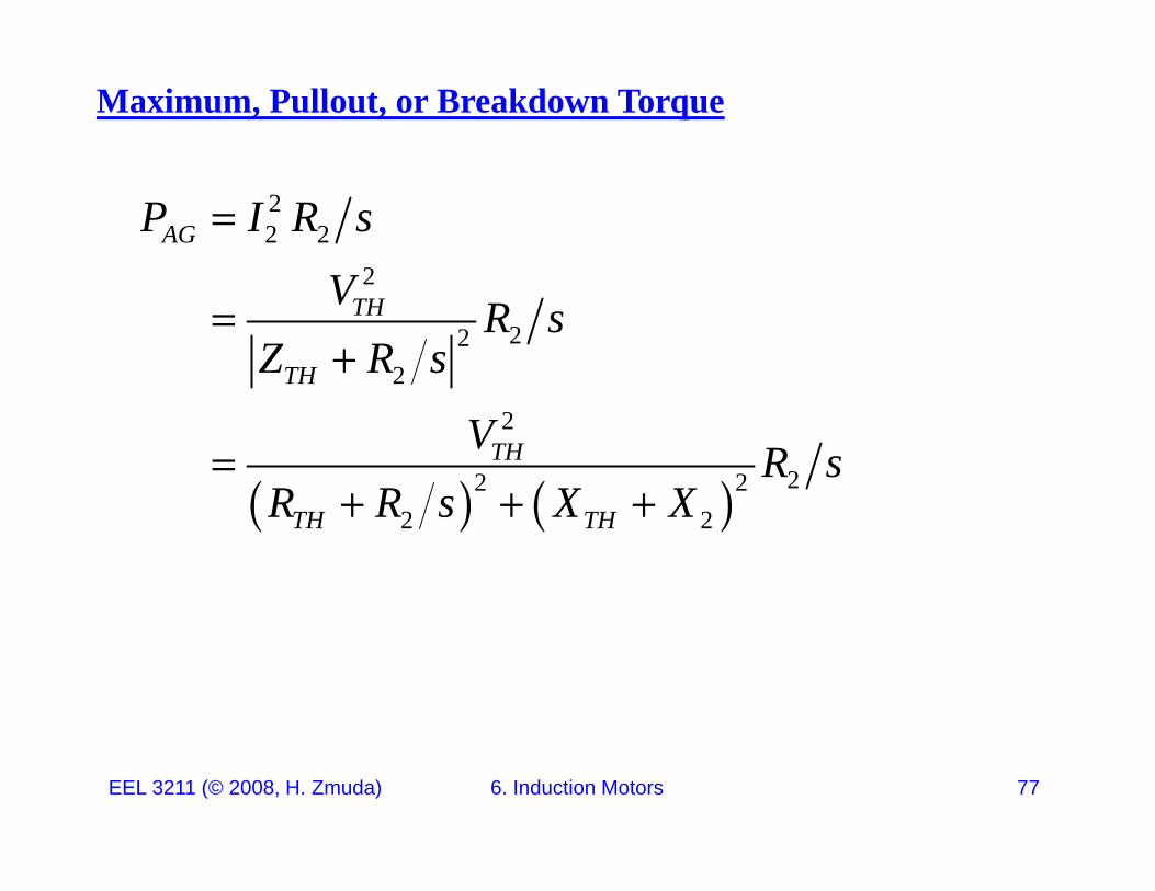
Maximum, Pullout, or Breakdown Torque
SinceAG
indsync
P
Maximum torque occurs when the air gap power is maximum.
sync
The air gap power is the power consumed by 2R s
When is this power maximum?
EEL 3211 (© 2008, H. Zmuda) 6. Induction Motors 74
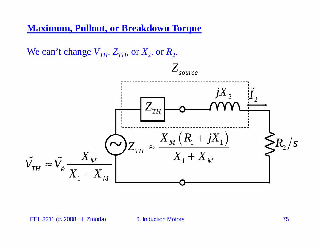
Maximum, Pullout, or Breakdown Torque
We can’t change VTH, ZTH, or X2, or R2.
sourceZ
2jX2I
Z
R
THZ
X R jX2R s~
MTH
XV VX X
1 1
1
MTH
M
X R jXZ
X X
1 MX X
EEL 3211 (© 2008, H. Zmuda) 6. Induction Motors 75
Maximum, Pullout, or Breakdown Torque
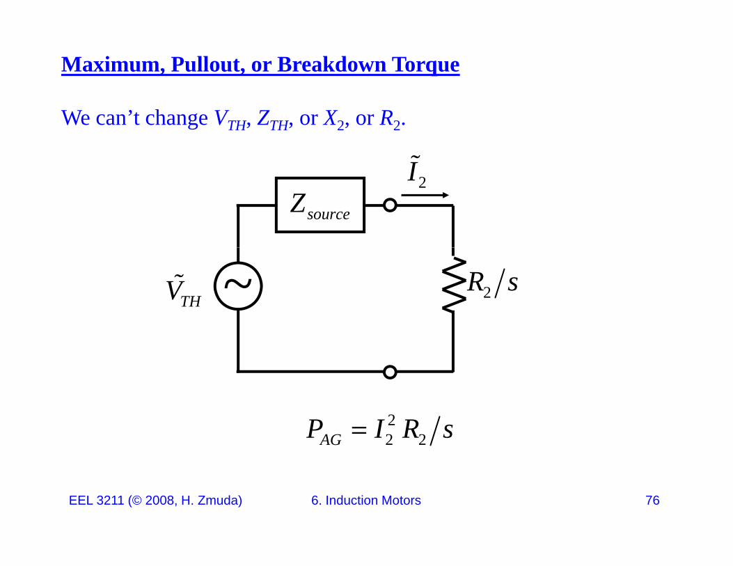
We can’t change VTH, ZTH, or X2, or R2.
I2IsourceZ
2R s~THV
22 2AGP I R s
EEL 3211 (© 2008, H. Zmuda) 6. Induction Motors 76
Maximum, Pullout, or Breakdown Torque
22 2
2
AGP I R s
V
2
222
TH
TH
V R sZ R s
2
22 2THV R s
R R s X X
2 2TH THR R s X X
EEL 3211 (© 2008, H. Zmuda) 6. Induction Motors 77
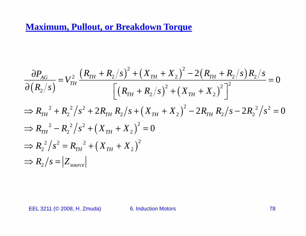
Maximum, Pullout, or Breakdown Torque
2 2 2R R s X X R R s R sP
2 2 2 2222 2
22 2
20TH TH THAG
TH
TH TH
R R s X X R R s R sP VR s R R s X X
22 2 2 2 22 2 2 2 2
22 2 22 2
2 2 2 0
0TH TH TH TH
TH TH
R R s R R s X X R R s R s
R R s X X
2 2
22 2 22 2
TH TH
TH THR s R X X
R s Z
2 sourceR s Z
EEL 3211 (© 2008, H. Zmuda) 6. Induction Motors 78
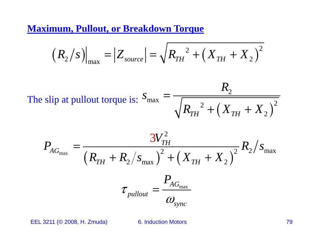
Maximum, Pullout, or Breakdown Torque
2 222 2max source TH THR s Z R X X
The slip at pullout torque is:
2max 22
RsR X X
2TH THR X X
23 THV max 2 max2 2
2 max 2
3 THAG
TH TH
VP R sR R s X X
maxAGpullout
sync
P
EEL 3211 (© 2008, H. Zmuda) 6. Induction Motors 79
sync
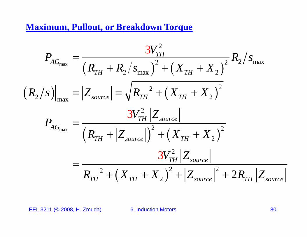
Maximum, Pullout, or Breakdown Torque
2
max
2
2 max2 22 max 2
3 THAG
TH TH
VP R sR R s X X
2 max 2
222 2max
TH TH
source TH THR s Z R X X
max
2
2 2
3 TH sourceAG
V ZP
R Z X X
2
23TH source TH
TH source
R Z X X
V Z
222
2 2TH TH source TH sourceR X X Z R Z
EEL 3211 (© 2008, H. Zmuda) 6. Induction Motors 80
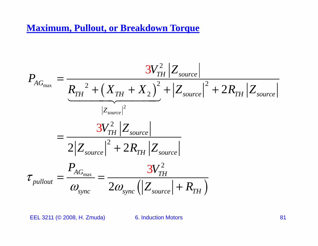
Maximum, Pullout, or Breakdown Torque
23 TH sourceV ZP
max
2
2222 2
AGTH TH source TH source
PR X X Z R Z
2
23sourceZ
TH sourceV Z 2
23
2 2source TH source
AG
Z R ZP V
max 3
2AG TH
pulloutsync sync source TH
P VZ R
EEL 3211 (© 2008, H. Zmuda) 6. Induction Motors 81
Maximum, Pullout, or Breakdown Torque
Since
2max
Rs
th li t hi h i t i li l ti l t
maxsourceZ
the slip at which maximum torque occurs is linearly proportional to the rotor resistance though the value of the maximum torque is independent of the value of the rotor resistance.
max
23AG THP V
max
2TH
pulloutsync sync source THZ R
EEL 3211 (© 2008, H. Zmuda) 6. Induction Motors 82
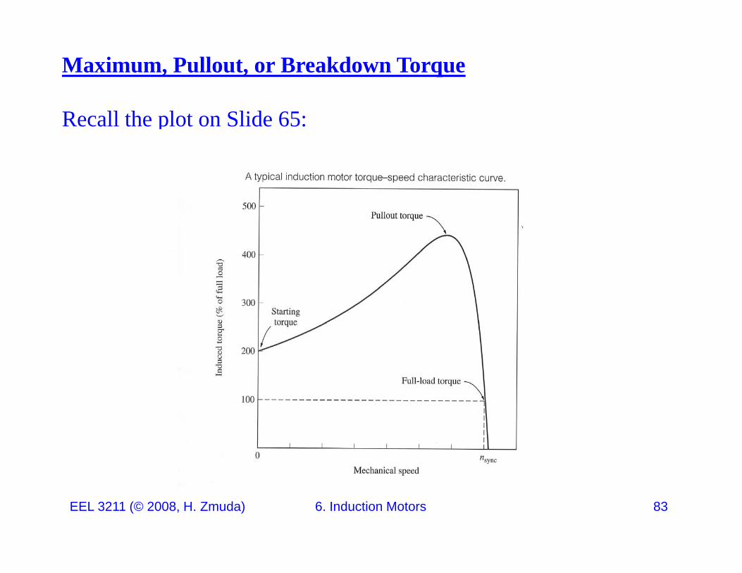
Maximum, Pullout, or Breakdown Torque
Recall the plot on Slide 65:
EEL 3211 (© 2008, H. Zmuda) 6. Induction Motors 83
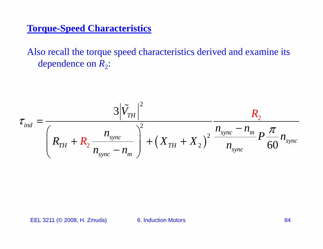
Torque-Speed Characteristics
Also recall the torque speed characteristics derived and examine its dependence on R2:
23 V
22
2
3 THind
sync msync sync
Vn nn P nR X X
R
R
2 2 60
y syncTH TH sync
sync m
R X X nnR
n
EEL 3211 (© 2008, H. Zmuda) 6. Induction Motors 84
Torque-Speed Characteristics
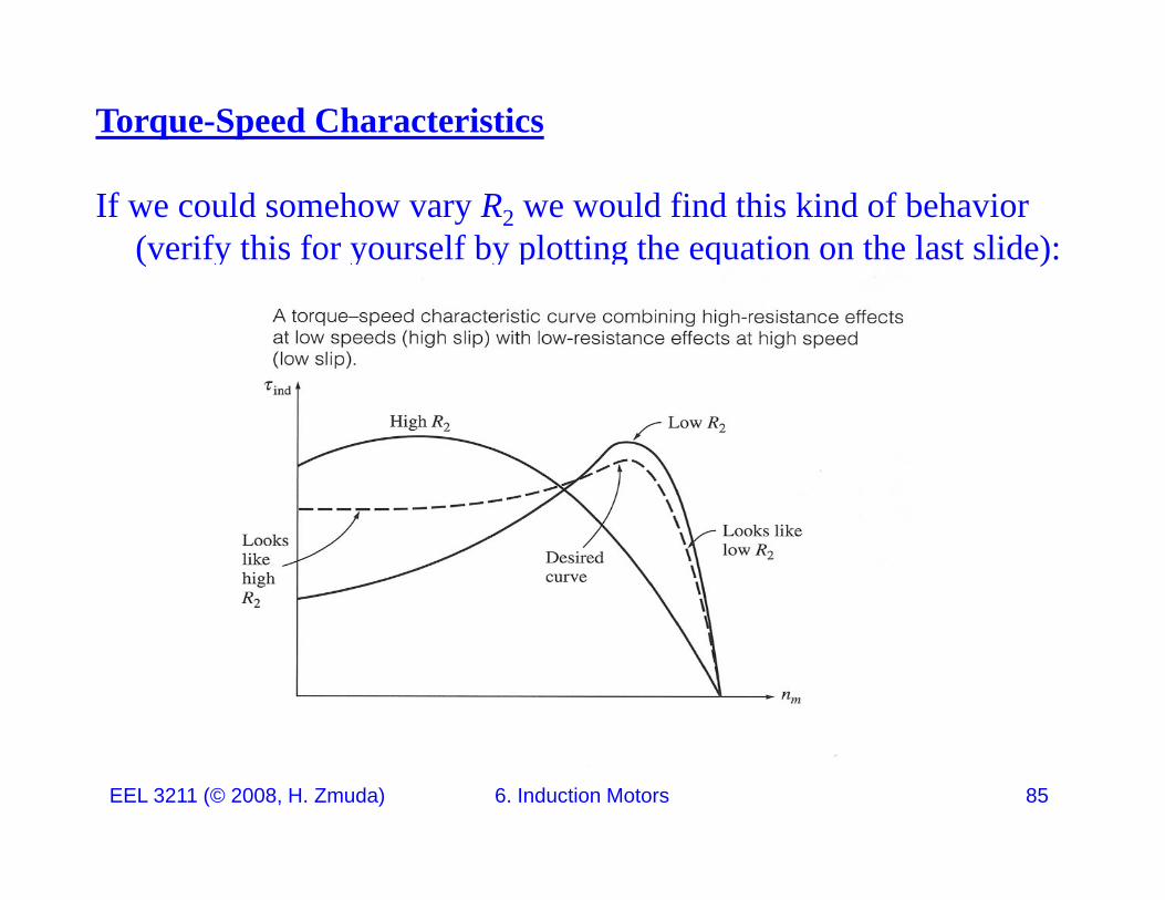
If we could somehow vary R2 we would find this kind of behavior (verify this for yourself by plotting the equation on the last slide):
EEL 3211 (© 2008, H. Zmuda) 6. Induction Motors 85
Torque-Speed Characteristics
If a rotor is designed with high resistance, the starting torque is quite high, but the slip is also quite high under normal operating
di iconditions.
Recall from Slide 47: . 1conv AGP P s
The higher the slip, the smaller the fraction of air-gap power converted to mechanical power thus the smaller the efficiency
converted to mechanical power, thus the smaller the efficiency.
Hence a motor with high starting torque has poor efficiency at l ti dnormal operating speeds.
EEL 3211 (© 2008, H. Zmuda) 6. Induction Motors 86
Torque-Speed Characteristics
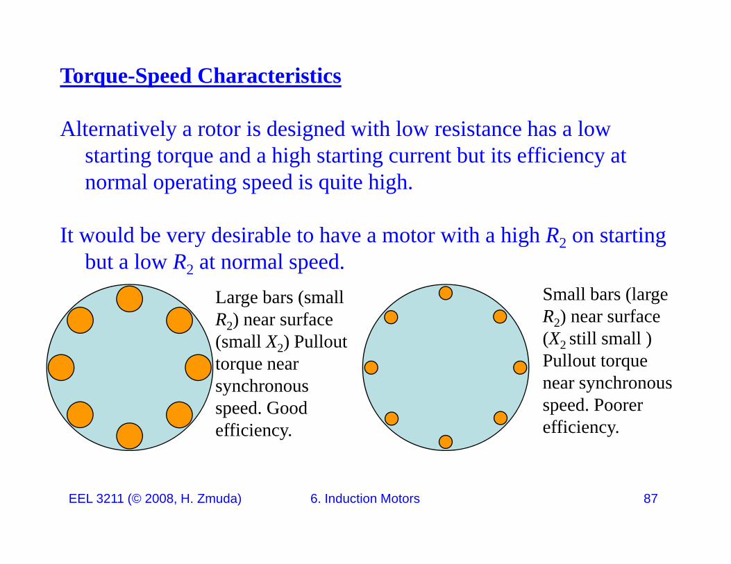
Alternatively a rotor is designed with low resistance has a low starting torque and a high starting current but its efficiency at
l i d i i hi hnormal operating speed is quite high.
It would be very desirable to have a motor with a high R2 on starting y g 2 gbut a low R2 at normal speed.
Large bars (small R ) near surface
Small bars (large R ) near surfaceR2) near surface
(small X2) Pullout torque near synchronous
R2) near surface (X2 still small ) Pullout torque near synchronous synchronous
speed. Good efficiency.
yspeed. Poorer efficiency.
EEL 3211 (© 2008, H. Zmuda) 6. Induction Motors 87
Torque-Speed Characteristics
The desirable feature of having a motor with a high R2 on starting but a low R2 at normal speed can actually be accomplished by taking d f h l k i h d i f i d iadvantage of the leakage reactance in the design of an induction
motor.
Keep in mind:
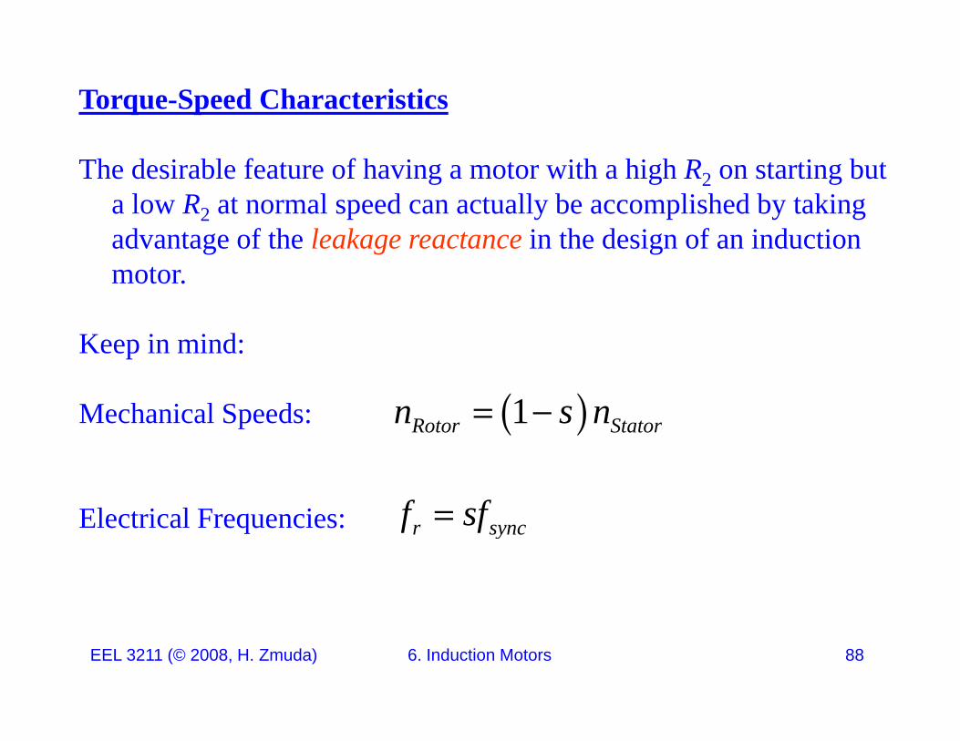
Mechanical Speeds: 1n s n Mechanical Speeds:
El t i l F i
1Rotor Statorn s n
f sfElectrical Frequencies: r syncf sf
EEL 3211 (© 2008, H. Zmuda) 6. Induction Motors 88
Torque-Speed Characteristics
An ingenious and simple way of obtaining a rotor resistance which will automatically vary with speed makes use of the fact that at
d ill h f l h f hstandstill the rotor frequency equals the stator frequency; as the motor accelerates, the rotor frequency decreases to a very low value, perhaps 2 or 3 Hz at full load in a 60-Hz motor. p p
Squirrel-cage rotors can be designed so that their effective resistance at 60 Hz is several times their resistance at 2 or 3 Hz The variousat 60 Hz is several times their resistance at 2 or 3 Hz. The various schemes all make use of the inductive effect of the slot-leakage flux on the current distribution in the rotor bars.
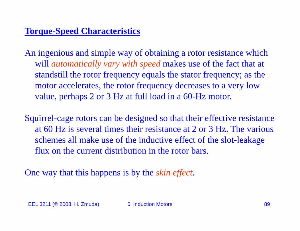
One way that this happens is by the skin effect.
EEL 3211 (© 2008, H. Zmuda) 6. Induction Motors 89
Skin Effect: Gives depth of penetration into a (real) conductor as a function of frequency asfunction of frequency as
2 1f
z
oI z I e
oI value at surface
1
oI I e
Perfect Conductor
Real Conductor
z
Current flows entirely on the conductor surface.
Current penetratesinto the conductor.
EEL 3211 (© 2008, H. Zmuda) 6. Induction Motors 90

Skin Effect:
Current distribution due to skin effect. The higher the frequency the more the current flows on the conductor surface giving a smaller effective area and hence a larger R
EEL 3211 (© 2008, H. Zmuda) 6. Induction Motors 91
smaller effective area and hence a larger R2.
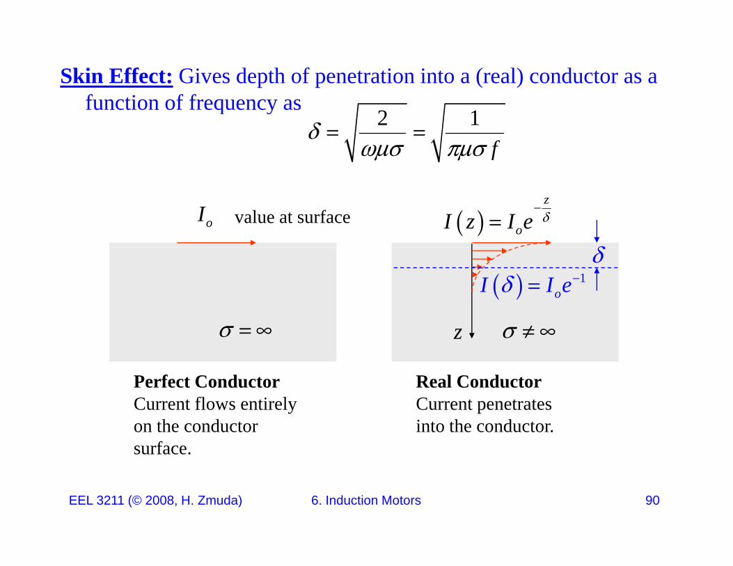
Torque-Speed Characteristics
Leakage Resistance Skin Depth:
2 12 1f
Resistance:
R A
EEL 3211 (© 2008, H. Zmuda) 6. Induction Motors 92

Torque-Speed Characteristics
Leakage Resistance
d
d
w w
2 1f
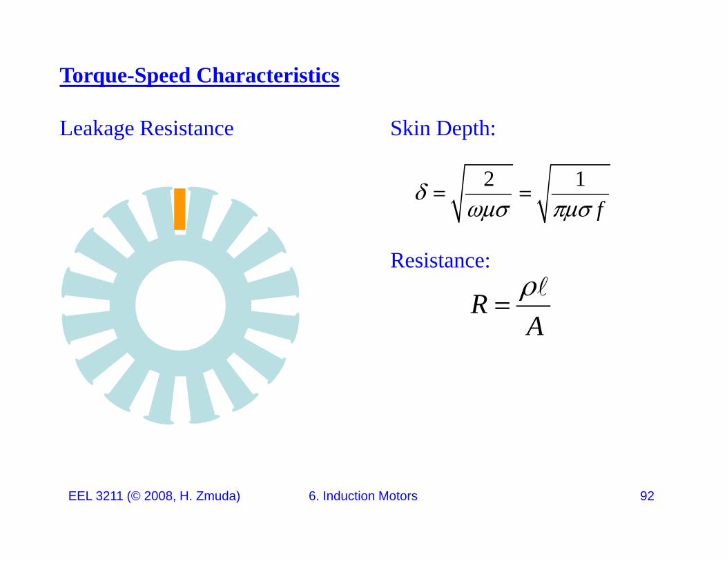
EEL 3211 (© 2008, H. Zmuda) 6. Induction Motors 93
f
Torque-Speed Characteristics
Leakage Resistance
dA wd 2 2A A w d
dA wd 2 2effA A w d
w w
2 1f
EEL 3211 (© 2008, H. Zmuda) 6. Induction Motors 94
f
Torque-Speed Characteristics
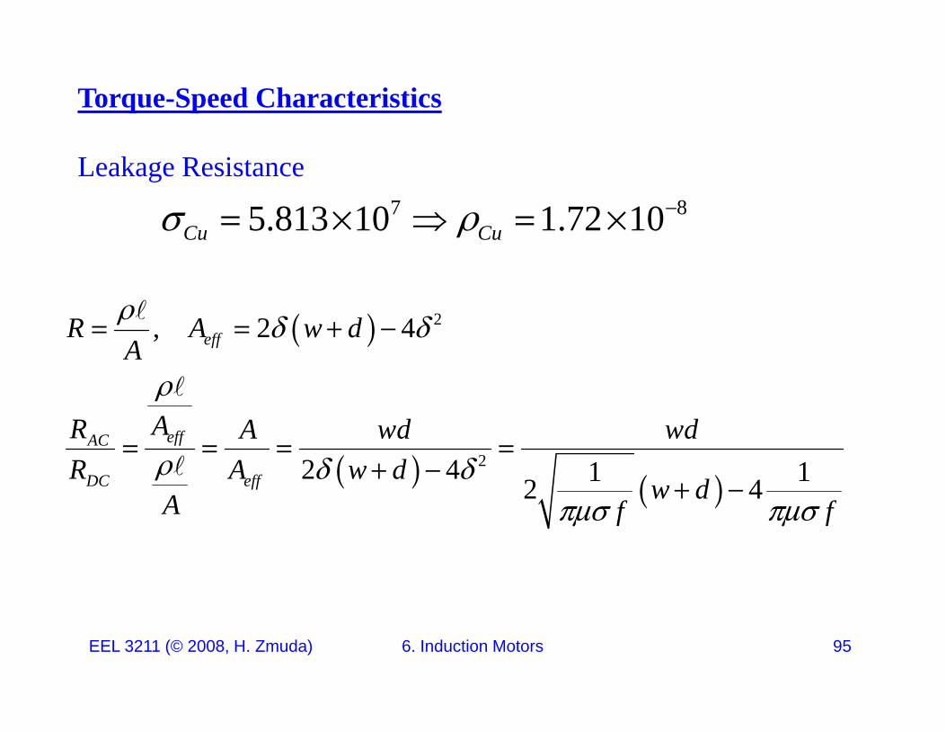
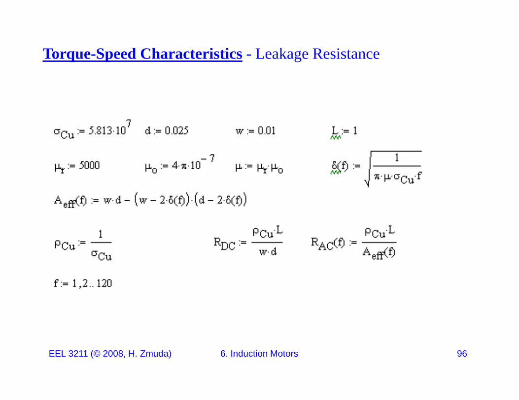
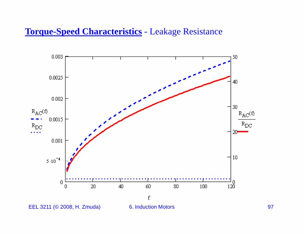
Leakage Resistance7 85.813 10 1.72 10C C 5.813 10 1.72 10Cu Cu
22 4R A d 2, 2 4effR A w dA
22 4 1 12 4
effAC
DC eff
AR A wd wdR A w d
w dA f f
A f f
EEL 3211 (© 2008, H. Zmuda) 6. Induction Motors 95
Torque-Speed Characteristics - Leakage Resistance
EEL 3211 (© 2008, H. Zmuda) 6. Induction Motors 96
Torque-Speed Characteristics - Leakage Resistance
EEL 3211 (© 2008, H. Zmuda) 6. Induction Motors 97
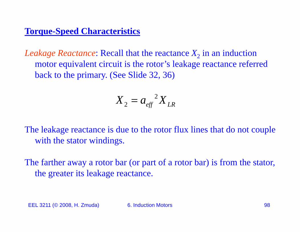
Torque-Speed Characteristics
Leakage Reactance: Recall that the reactance X2 in an induction motor equivalent circuit is the rotor’s leakage reactance referred b k h i (S Slid 32 36)back to the primary. (See Slide 32, 36)
2X a X
The leakage reactance is due to the rotor flux lines that do not couple
2 eff LRX a X
The leakage reactance is due to the rotor flux lines that do not couple with the stator windings.
Th f th t b ( t f t b ) i f th t tThe farther away a rotor bar (or part of a rotor bar) is from the stator, the greater its leakage reactance.
EEL 3211 (© 2008, H. Zmuda) 6. Induction Motors 98
Torque-Speed Characteristics
Leakage Reactance: If the squirrel cage bars are placed close to the surface of the rotor, the leakage reactance will be small (X2 will be
ll) If h b l d d i h f f hsmall). If the rotor bars are placed deep in the surface of the rotor, the leakage will be greater and X2 will be larger.
EEL 3211 (© 2008, H. Zmuda) 6. Induction Motors 99
X
Torque-Speed CharacteristicsX
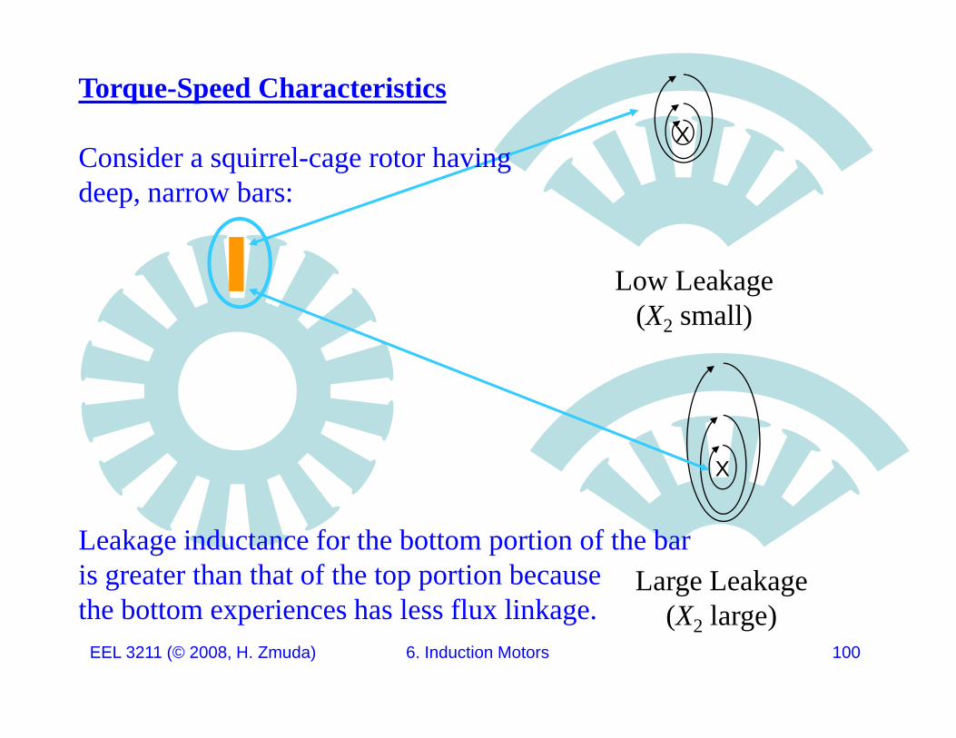
Consider a squirrel-cage rotor havingdeep, narrow bars:
Low Leakage(X2 small)(X2 small)
X
Large LeakageLeakage inductance for the bottom portion of the baris greater than that of the top portion becauseth b tt i h l fl li k
EEL 3211 (© 2008, H. Zmuda) 6. Induction Motors 100
(X2 large)the bottom experiences has less flux linkage.
Torque-Speed Characteristics
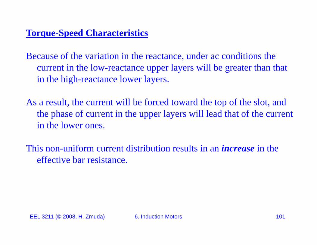
Because of the variation in the reactance, under ac conditions the current in the low-reactance upper layers will be greater than that i h hi h l lin the high-reactance lower layers.
As a result, the current will be forced toward the top of the slot, and pthe phase of current in the upper layers will lead that of the current in the lower ones.
This non-uniform current distribution results in an increase in the effective bar resistance.
EEL 3211 (© 2008, H. Zmuda) 6. Induction Motors 101
Torque-Speed Characteristics
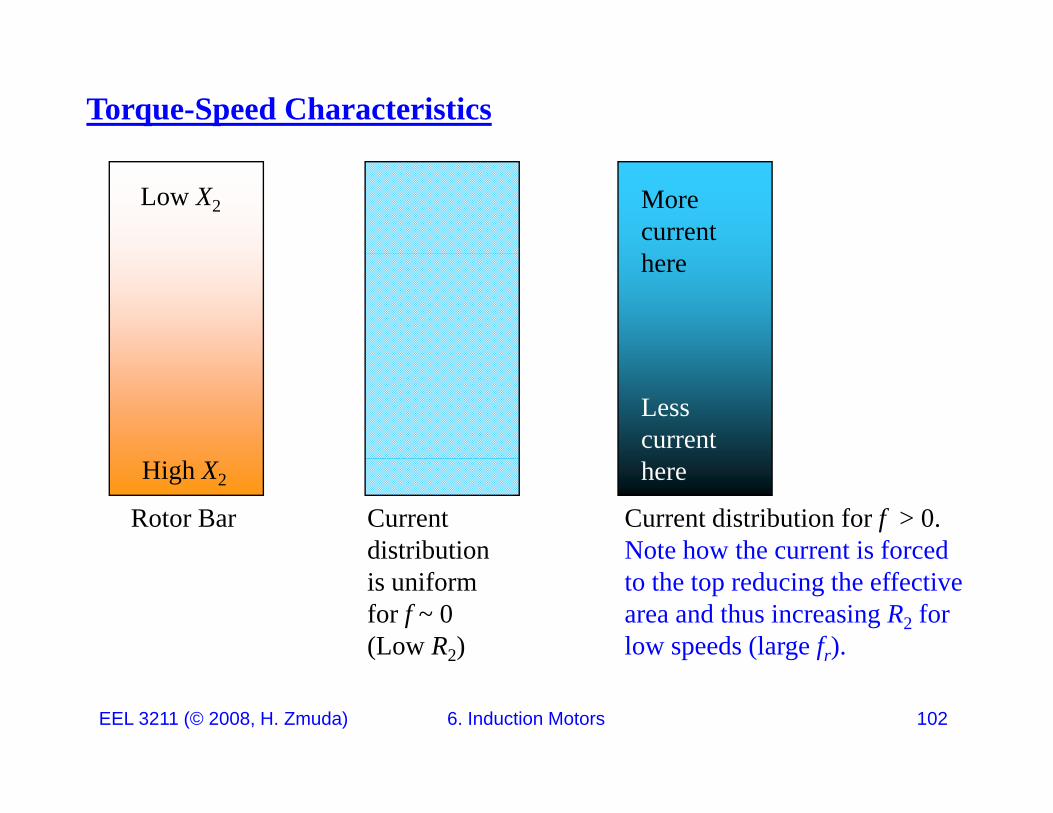
Low X2 More currenthere
Less current
Rotor Bar
High X2
Current distribution
Current distribution for f > 0. Note how the current is forced
here
is uniform for f ~ 0(Low R2)
to the top reducing the effective area and thus increasing R2 for low speeds (large fr).
EEL 3211 (© 2008, H. Zmuda) 6. Induction Motors 102
Torque-Speed Characteristics
The result is that the current in the low-reactance upper layers will be greater than that in the high-reactance lower layers. As a result, the current will be forced toward the top of the slot and the phase ofcurrent will be forced toward the top of the slot, and the phase of current in the upper layers will lead that of the current in the lower ones.
This non-uniform current distribution results in an increase in the effective bar resistance and a smaller decrease in the effective leakage inductance of the bar.
EEL 3211 (© 2008, H. Zmuda) 6. Induction Motors 103
Torque-Speed Characteristics
Consequently a squirrel-cage rotor with deep bars can bereadily designed to have an effective resistance at stator frequency
(corresponding to rotor standstill conditions) several times greater(corresponding to rotor standstill conditions) several times greater than its dc resistance.
As the motor accelerates, the rotor frequency decreases and therefore the effective rotor resistance decreases, approaching its dc value at small slips.p
EEL 3211 (© 2008, H. Zmuda) 6. Induction Motors 104
Torque-Speed Characteristics
An alternative way of attaining similar results is the double-cage arrangement
shown on the next slideshown on the next slide.
The squirrel-cage winding consists of two layers of bars short-circuited by end rings. The upper bars are of smaller cross-sectional area than the lower bars and consequently have higher resistance.
As before, the inductance of the lower bars is greater than that of the upper ones At standstillupper ones. At standstill,
EEL 3211 (© 2008, H. Zmuda) 6. Induction Motors 105
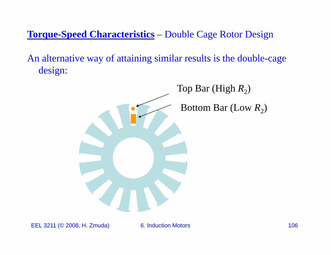
Torque-Speed Characteristics – Double Cage Rotor Design
An alternative way of attaining similar results is the double-cage design:
Top Bar (High R2)
Bottom Bar (Low R2)( 2)
EEL 3211 (© 2008, H. Zmuda) 6. Induction Motors 106
Torque-Speed Characteristics
At standstill, when rotor frequency equals stator frequency, there is relatively little current in the lower bars because of their high reactance; the effective resistance of the rotor at standstill is thenreactance; the effective resistance of the rotor at standstill is then approximately equal to that of the high-resistance upper layer.
At the low rotor frequencies corresponding to small slips, however, reactance effects become negligible, and the rotor resistance then approaches that of the two layers in parallel.pp y p
EEL 3211 (© 2008, H. Zmuda) 6. Induction Motors 107
Torque-Speed Characteristics
The upper bars are of smaller cross-sectional area than the lower bars and consequently have higher resistance.
The inductance of the lower bars is greater than that of the upper ones because of the flux crossing the slot between the two layers. g y
The difference in inductance can be made quite large byproperly proportioning the constriction in the slot between the twoproperly proportioning the constriction in the slot between the two
bars.
EEL 3211 (© 2008, H. Zmuda) 6. Induction Motors 108

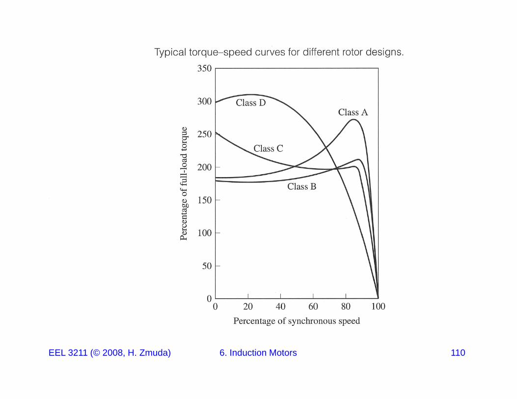
Summary: By use of double-cage and deep-bar rotors, squirrel-cage motors can be designed to have the good starting characteristics resulting from high rotor resistance and, at the same time, the good running characteristics resulting from low rotor resistance. Induction motorsresulting from low rotor resistance. Induction motors generally fall into four types:
Class A: Normal Starting Torque Normal StartingClass A: Normal Starting Torque, Normal Starting Current, Low Slip
Class B: Normal Starting Torque, Low Starting Current, Low Slip
Class C: High Starting Torque, Low Starting Current
Class D: High Starting Torque High SlipEEL 3211 (© 2008, H. Zmuda) 6. Induction Motors 109
Class D: High Starting Torque, High Slip
EEL 3211 (© 2008, H. Zmuda) 6. Induction Motors 110
Starting Induction Motors and Speed Control
Clearly, by their very nature, inductions motors tend to be self starting. Electronics is used to limit the starting current.
The speed can be somewhat controlled with line voltage. Another method of speed control uses power electronic circuits to vary the p p yline current.
Read Section 7 7 and 7 8 for a discussion on these topicsRead Section 7.7 and 7.8 for a discussion on these topics.
EEL 3211 (© 2008, H. Zmuda) 6. Induction Motors 111
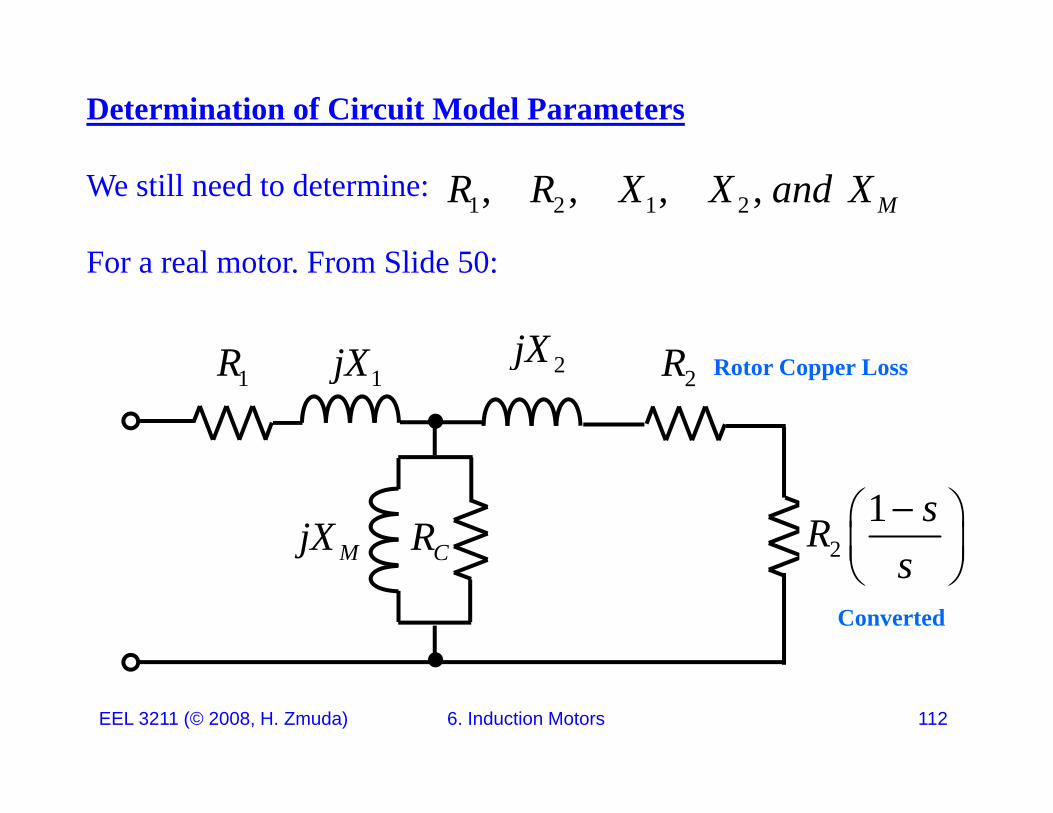
Determination of Circuit Model Parameters
We still need to determine:
F l F Slid 50
1 2 1 2, , , , MR R X X and X
For a real motor. From Slide 50:
jXR jX R1jX1R 2jX2R Rotor Copper Loss
CRMjX 21 sR
s
s
Converted
EEL 3211 (© 2008, H. Zmuda) 6. Induction Motors 112
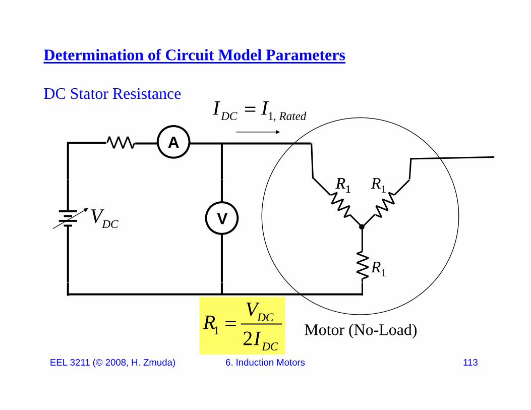
Determination of Circuit Model Parameters
DC Stator Resistance1,DC RatedI I
R
A
R RR1
V
R1 R1
DCV
R1
Motor (No-Load)1 2DCVRI
EEL 3211 (© 2008, H. Zmuda) 6. Induction Motors 113
Motor (No Load)2 DCI
Determination of Circuit Model Parameters No-Load Test –
Measures rotational losses and provides magnetization current.
1 Th i f l h l l d h f i i d1. The motor spins freely, so the only loads are the friction and windage losses.
2. All Pconv in this motor is consumed by mechanical losses.
3 The slip is very small3. The slip is very small.
EEL 3211 (© 2008, H. Zmuda) 6. Induction Motors 114
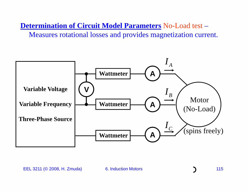
Determination of Circuit Model Parameters No-Load test –Measures rotational losses and provides magnetization currentMeasures rotational losses and provides magnetization current.
IA
AIWattmeter
Variable Voltage
Variable Frequency
V
ABI
Motor(N L d)
Wattmeter
Three-Phase SourceCI
(No-Load)
(spins freely)A (spins freely)Wattmeter
EEL 3211 (© 2008, H. Zmuda) 6. Induction Motors 115
Determination of Circuit Model Parameters No-Load Test
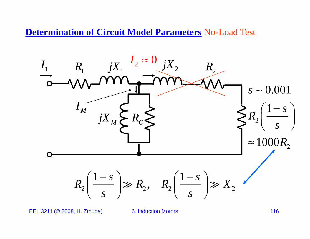
1jX1R 2jX2R2 0I
1I
0.0011
s
I
CRMjX 21 sR
s
MI
21000R
2 2 2 21 1,s sR R R X
s s
EEL 3211 (© 2008, H. Zmuda) 6. Induction Motors 116
s s
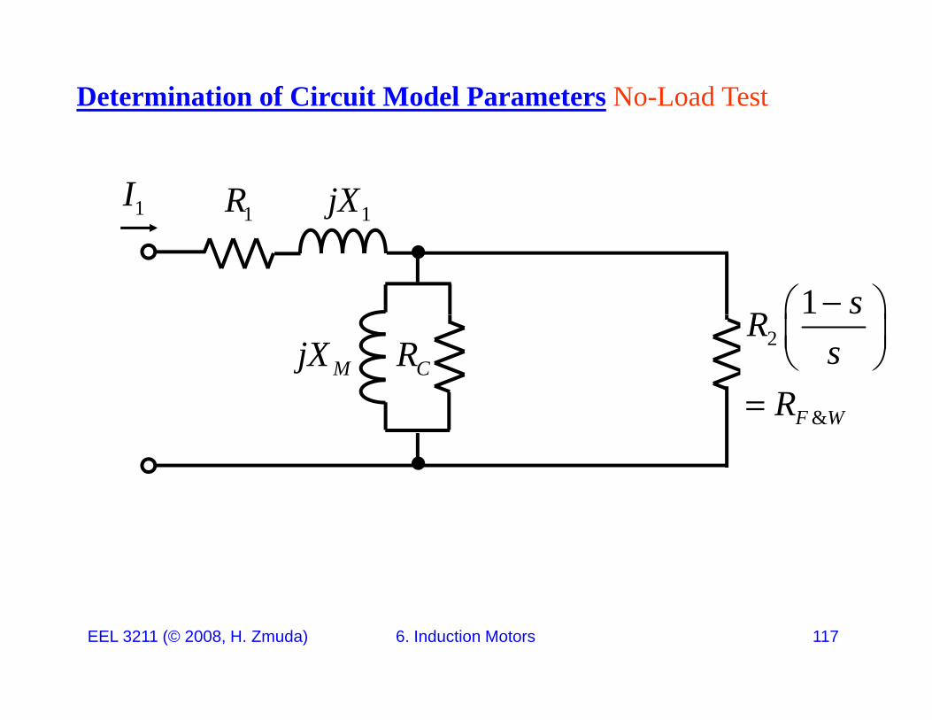
Determination of Circuit Model Parameters No-Load Test
1jX1R1I
1 sR
CRMjX 2Rs
R
&F WR
EEL 3211 (© 2008, H. Zmuda) 6. Induction Motors 117
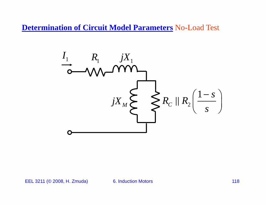
Determination of Circuit Model Parameters No-Load Test
1jX1R1I
2
1C
sR Rs
MjX
EEL 3211 (© 2008, H. Zmuda) 6. Induction Motors 118
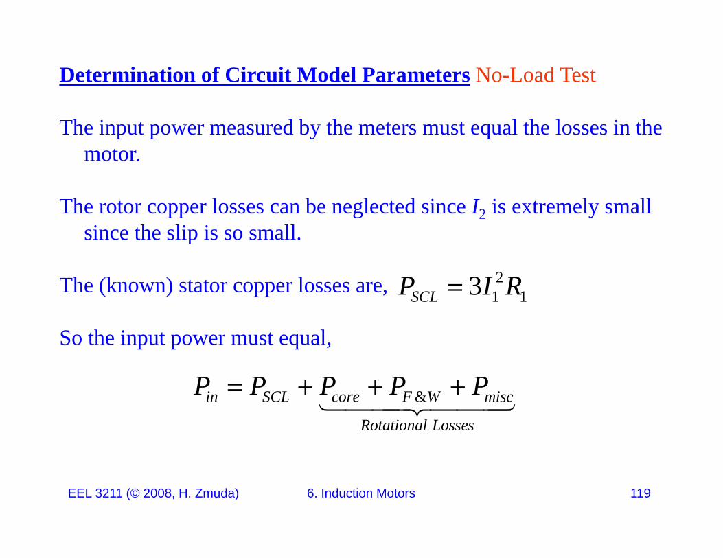
Determination of Circuit Model Parameters No-Load Test
The input power measured by the meters must equal the losses in the motor.
The rotor copper losses can be neglected since I2 is extremely small since the slip is so small.p
The (known) stator copper losses are, 21 13SCLP I R
So the input power must equal,
P P P P P &in SCL core F W misc
Rotational Losses
P P P P P
EEL 3211 (© 2008, H. Zmuda) 6. Induction Motors 119

Determination of Circuit Model Parameters No-Load Test
1jX1R1I2
1M C
sX R R
1 s
2M C s
21
CsR R
s
MjX
Th t d d t t bli h ti fi ld i it lThe current needed to establish a magnetic field is quite large because of the large reluctance of its air gap, hence the reactance XM will be much smaller than the resistances in parallel with it.
EEL 3211 (© 2008, H. Zmuda) 6. Induction Motors 120
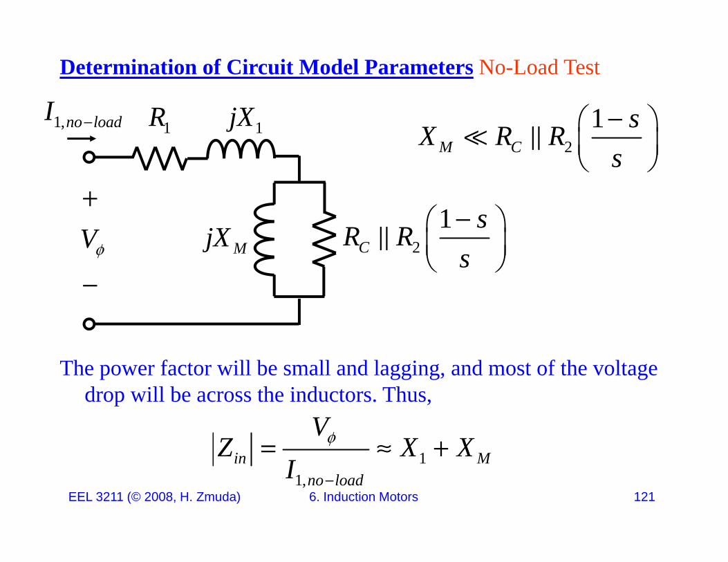
Determination of Circuit Model Parameters No-Load Test
I 1jX1R1,no loadI 2
1M C
sX R Rs
21
CsR R
MjXV
2C s
MjXV
The power factor will be small and lagging, and most of the voltage d ill b h i d Thdrop will be across the inductors. Thus,
1in M
VZ X X
EEL 3211 (© 2008, H. Zmuda) 6. Induction Motors 121
11,
in Mno loadI
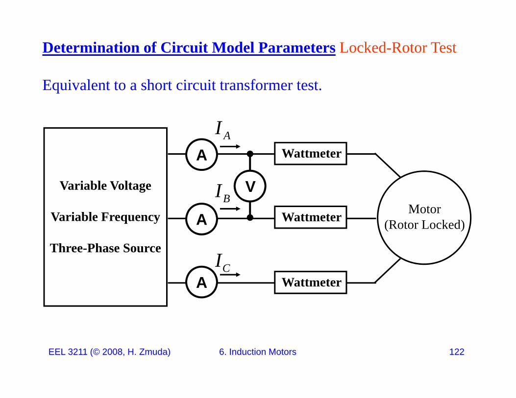
Determination of Circuit Model Parameters Locked-Rotor Test
Equivalent to a short circuit transformer test.
IA
AIWattmeter
Variable Voltage
Variable Frequency
V
ABI
Motor(Rotor Locked)Wattmeter
Three-Phase Source
A
CI
(Rotor Locked)
A Wattmeter
EEL 3211 (© 2008, H. Zmuda) 6. Induction Motors 122
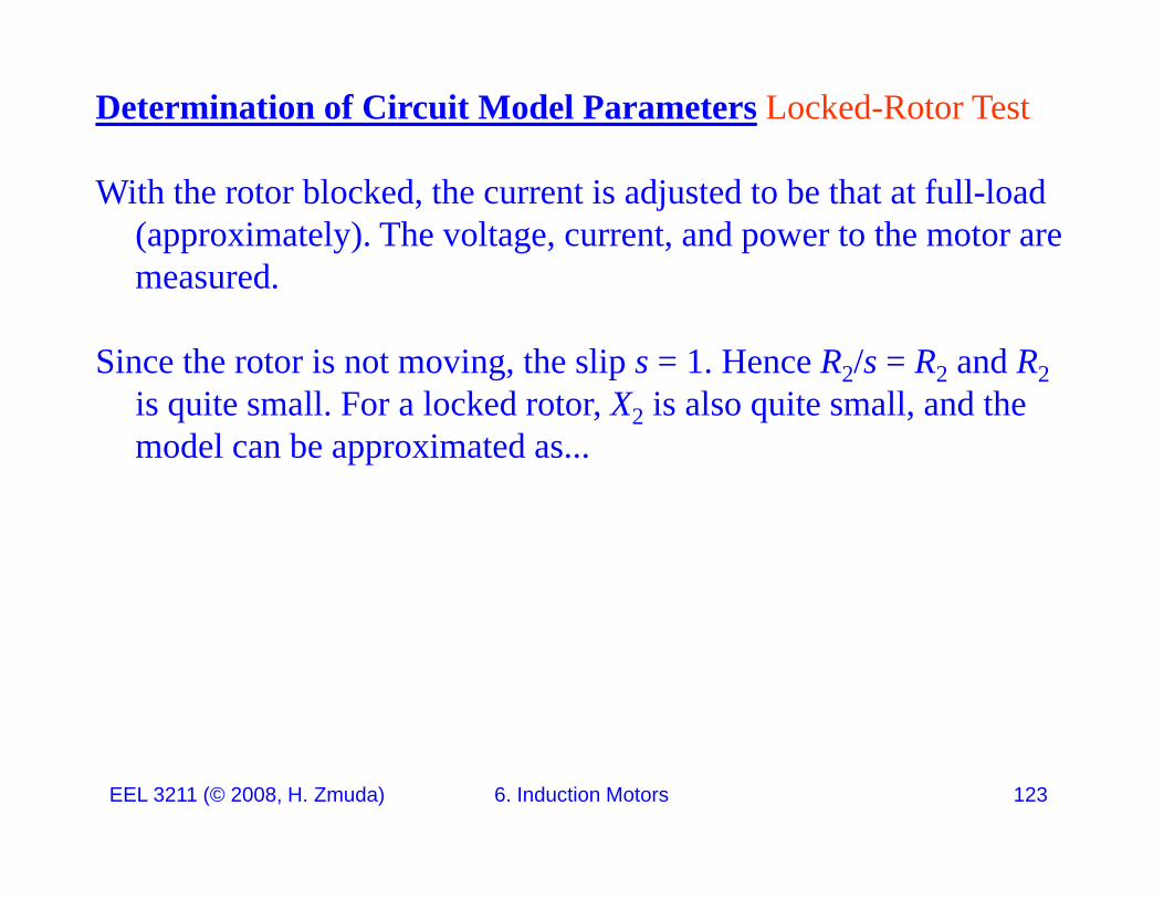
Determination of Circuit Model Parameters Locked-Rotor Test
With the rotor blocked, the current is adjusted to be that at full-load (approximately). The voltage, current, and power to the motor are measuredmeasured.
Since the rotor is not moving, the slip s = 1. Hence R2/s = R2 and R2i i ll F l k d X i l i ll d his quite small. For a locked rotor, X2 is also quite small, and the model can be approximated as...
EEL 3211 (© 2008, H. Zmuda) 6. Induction Motors 123
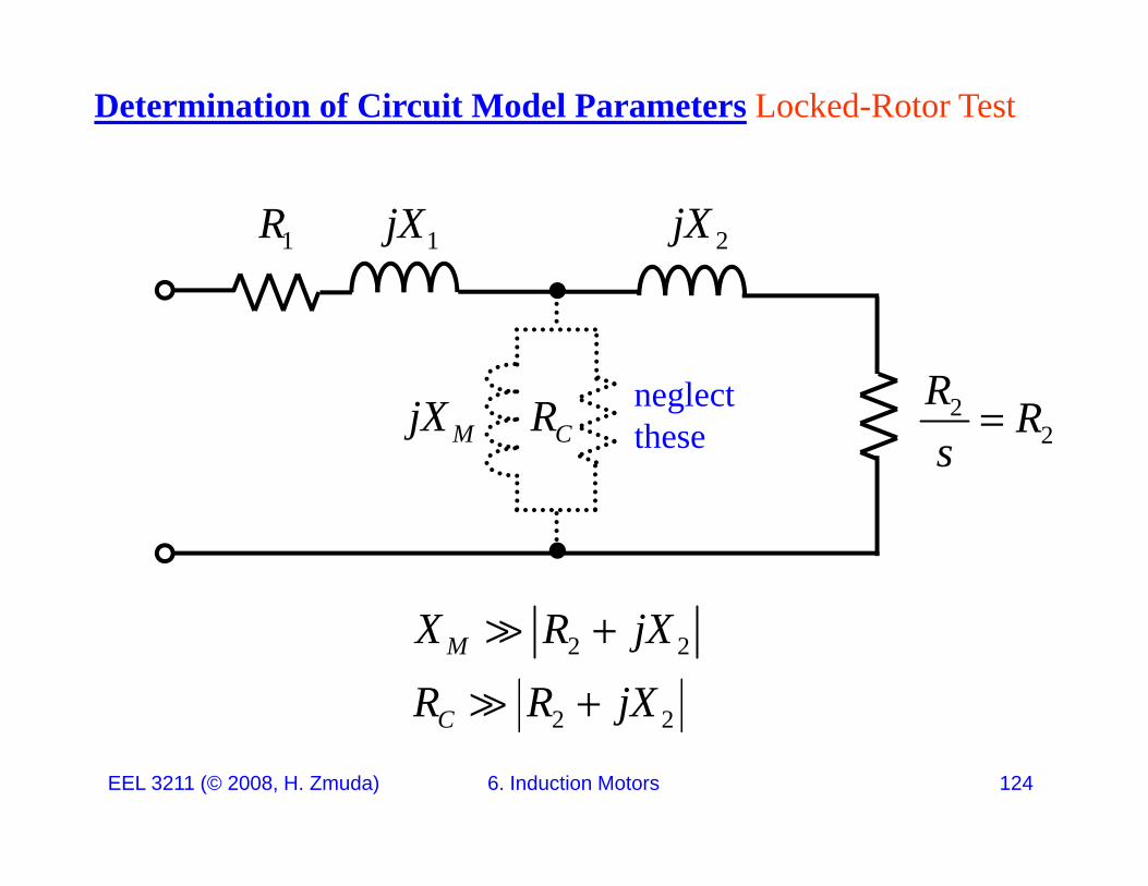
Determination of Circuit Model Parameters Locked-Rotor Test
1jX1R 2jX
Rl tCRMjX 2
2R Rsneglect
these
2 2
2 2
M
C
X R jX
R R jX
EEL 3211 (© 2008, H. Zmuda) 6. Induction Motors 124
2 2C j
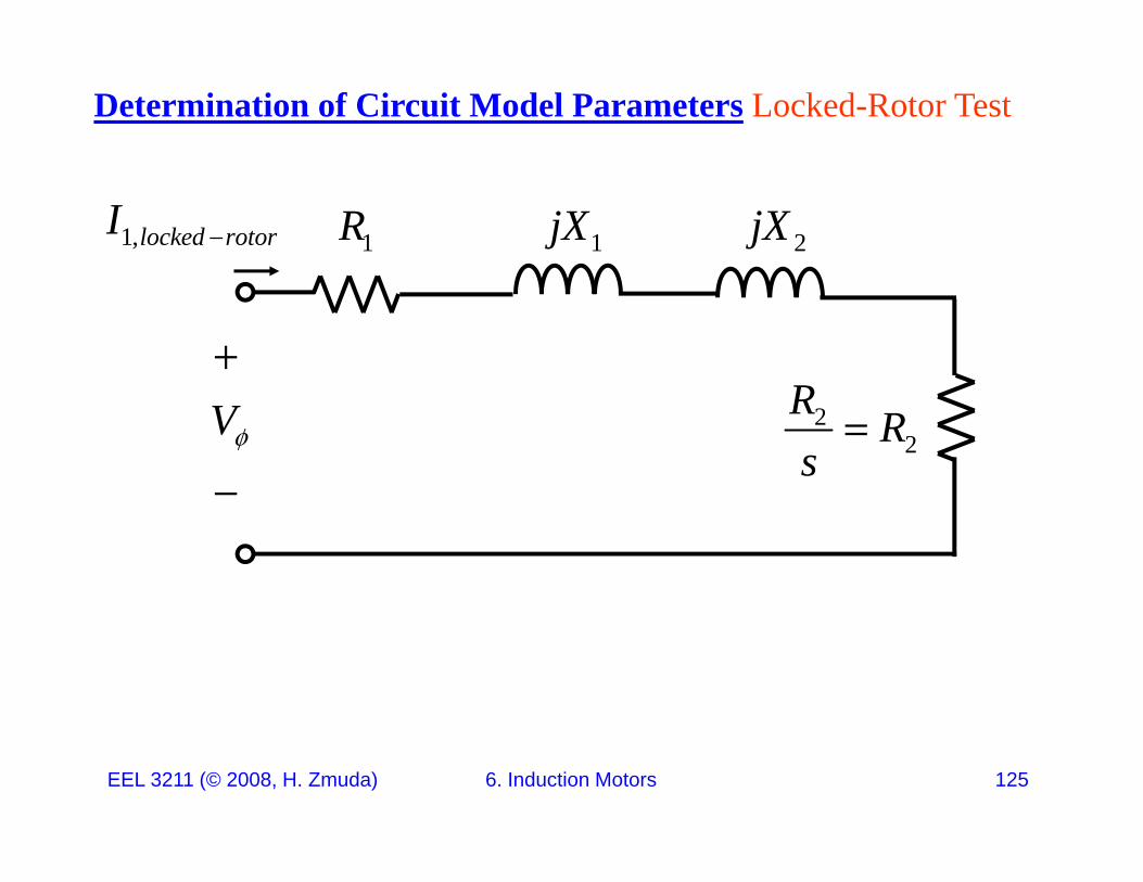
Determination of Circuit Model Parameters Locked-Rotor Test
1jX1R 2jX1,locked rotorI
R
22
R RsV
EEL 3211 (© 2008, H. Zmuda) 6. Induction Motors 125
Determination of Circuit Model Parameters Locked-Rotor Test
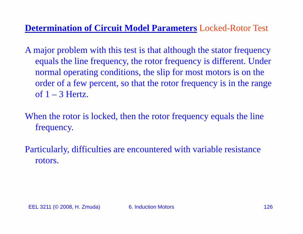
A major problem with this test is that although the stator frequency equals the line frequency, the rotor frequency is different. Under normal operating conditions the slip for most motors is on thenormal operating conditions, the slip for most motors is on the order of a few percent, so that the rotor frequency is in the range of 1 – 3 Hertz.
When the rotor is locked, then the rotor frequency equals the line frequency. q y
Particularly, difficulties are encountered with variable resistance rotorsrotors.
EEL 3211 (© 2008, H. Zmuda) 6. Induction Motors 126
Determination of Circuit Model Parameters Locked-Rotor Test
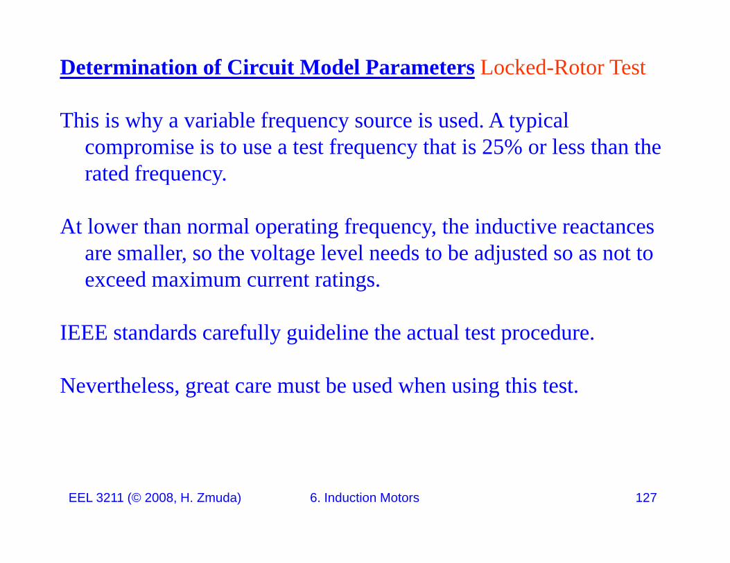
This is why a variable frequency source is used. A typical compromise is to use a test frequency that is 25% or less than the rated frequencyrated frequency.
At lower than normal operating frequency, the inductive reactances ll h l l l d b dj dare smaller, so the voltage level needs to be adjusted so as not to
exceed maximum current ratings.
IEEE standards carefully guideline the actual test procedure.
Nevertheless great care must be used when using this testNevertheless, great care must be used when using this test.
EEL 3211 (© 2008, H. Zmuda) 6. Induction Motors 127
Determination of Circuit Model Parameters Locked-Rotor Test
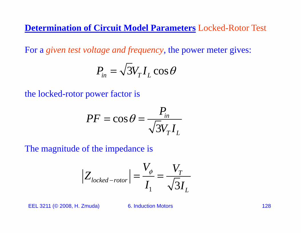
For a given test voltage and frequency, the power meter gives:
3 cosP V I
the locked-rotor power factor is
3 cosin T LP V I
cos3
in
T L
PPFV I
The magnitude of the impedance is
3 T LV I
1 3T
locked rotorL
V VZI I
EEL 3211 (© 2008, H. Zmuda) 6. Induction Motors 128
1 L
Determination of Circuit Model Parameters Locked-Rotor Test
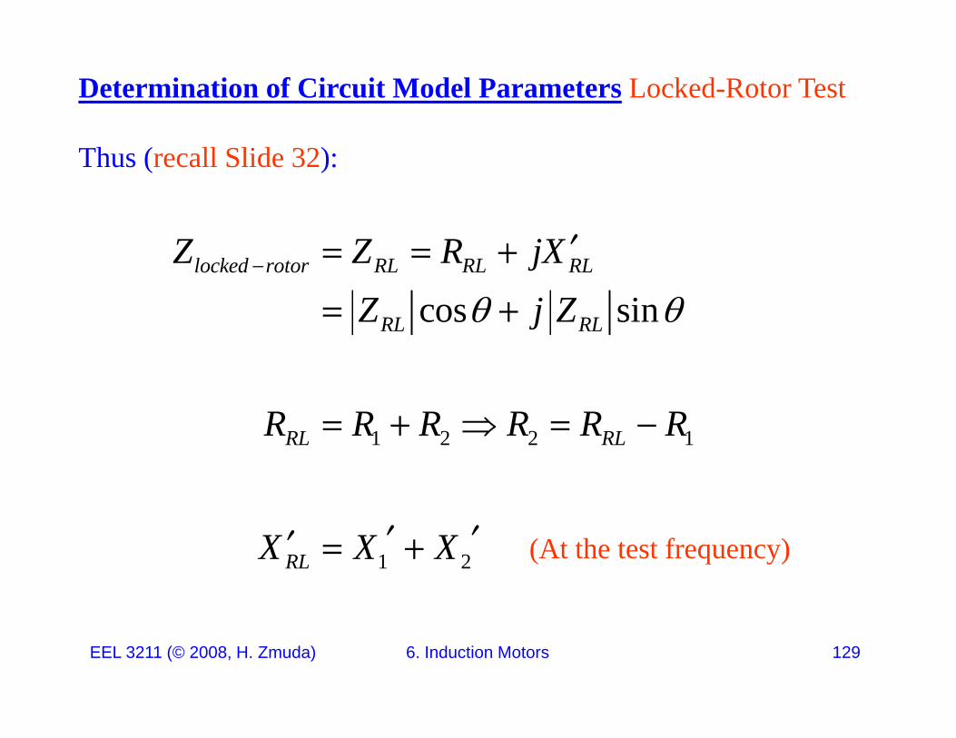
Thus (recall Slide 32):
cos sinlocked rotor RL RL RL
RL RL
Z Z R jXZ j Z
RL RLj
R R R R R R1 2 2 1RL RLR R R R R R
1 2RLX X X (At the test frequency)
EEL 3211 (© 2008, H. Zmuda) 6. Induction Motors 129
Determination of Circuit Model Parameters Locked-Rotor Test
Thus (recall Slide 32):
1 2 1 2RL t t RL t tX X X L L L
1 2 1 2RL test RL testX X X L L L
X L L L X X
1 2 1 2RL rated RL ratedX L L L X X
1 2 ,ratedRL rated ratedRL RL
fX Xf
L LXX L L
1
1 2
2
R test
ratedRL
L test test ffX X
X L
X
L
EEL 3211 (© 2008, H. Zmuda) 6. Induction Motors 130
1 2RLtestf
Determination of Circuit Model Parameters Locked-Rotor Test
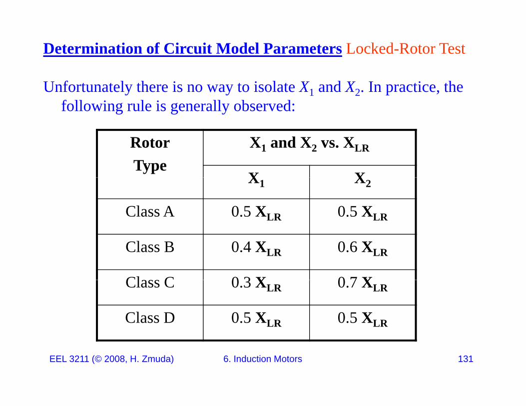
Unfortunately there is no way to isolate X1 and X2. In practice, the following rule is generally observed:
RotorType
X1 and X2 vs. XLR
X XX1 X2
Class A 0.5 XLR 0.5 XLR
Class B 0.4 XLR 0.6 XLR
Cl C 0 3 X 0 7 XClass C 0.3 XLR 0.7 XLR
Class D 0.5 XLR 0.5 XLR
EEL 3211 (© 2008, H. Zmuda) 6. Induction Motors 131
Induction Motor ExamplesSee Slide Set 6aSee Slide Set 6a
EEL 3211 (© 2008, H. Zmuda) 6. Induction Motors 132