6. design of water tanks -...
TRANSCRIPT
1
6. Design of Water Tanks(For class held on 23rd , 24th , 30th April 7th and 8th May 07)
By Dr. G.S.Suresh, Professor, Civil Engineering Department, NIE, Mysore(Ph:9342188467, email: gss_nie@ yahoo.com)
6.1 Introduction:Storage tanks are built for storing water, liquid petroleum, petroleum products andsimilar liquids. Analysis and design of such tanks are independent of chemical natureof product. They are designed as crack free structures to eliminate any leakage.Adequate cover to reinforcement is necessary to prevent corrosion. In order to avoidleakage and to provide higher strength concrete of grade M20 and above isrecommended for liquid retaining structures.To achieve imperviousness of concrete, higher density of concrete should beachieved. Permeability of concrete is directly proportional to water cement ratio.Proper compaction using vibrators should be done to achieve imperviousness.Cement content ranging from 330 Kg/m3 to 530 Kg/m3 is recommended in order tokeep shrinkage low.The leakage is more with higher liquid head and it has been observed that water headup to 15 m does not cause leakage problem. Use of high strength deformed bars ofgrade Fe415 are recommended for the construction of liquid retaining structures.However mild steel bars are also used. Correct placing of reinforcement, use of smallsized and use of deformed bars lead to a diffused distribution of cracks. A crackwidth of 0.1mm has been accepted as permissible value in liquid retaining structures.While designing liquid retaining structures recommendation of “Code of Practice forthe storage of Liquids- IS3370 (Part I to IV)” should be considered. Fracturedstrength of concrete is computed using the formula given in clause 6.2.2 of IS 456 -2000 ie., fcr=0.7fck MPa. This code does not specify the permissible stresses inconcrete for resistance to cracking. However earlier version of this code published in1964 recommends permissible value as cat= 0.27 fck for direct tension and cbt=0.37 fck for bending tensile strength.Allowable stresses in reinforcing steel as per IS 3370 arest= 115 MPa for Mild steel (Fe250) and st= 150 MPa for HYSD bars(Fe415)In order to minimize cracking due to shrinkage and temperature, minimumreinforcement is recommended as:i) For thickness 100 mm = 0.3 %ii) For thickness 450 mm = 0.2%iii) For thickness between 100 mm to 450 mm = varies linearly from 0.3% to
0.2%For concrete thickness 225 mm, two layers of reinforcement be placed, one nearwater face and other away from water face.Cover to reinforcement is greater of i) 25 mm, ii) Diameter of main bar.In case of concrete cross section where the tension occurs on fibers away from thewater face, then permissible stresses for steel to be used are same as in the analysis ofother sections, ie., st=140 MPa for Mild steel and st=230 MPa for HYSD bars.
2
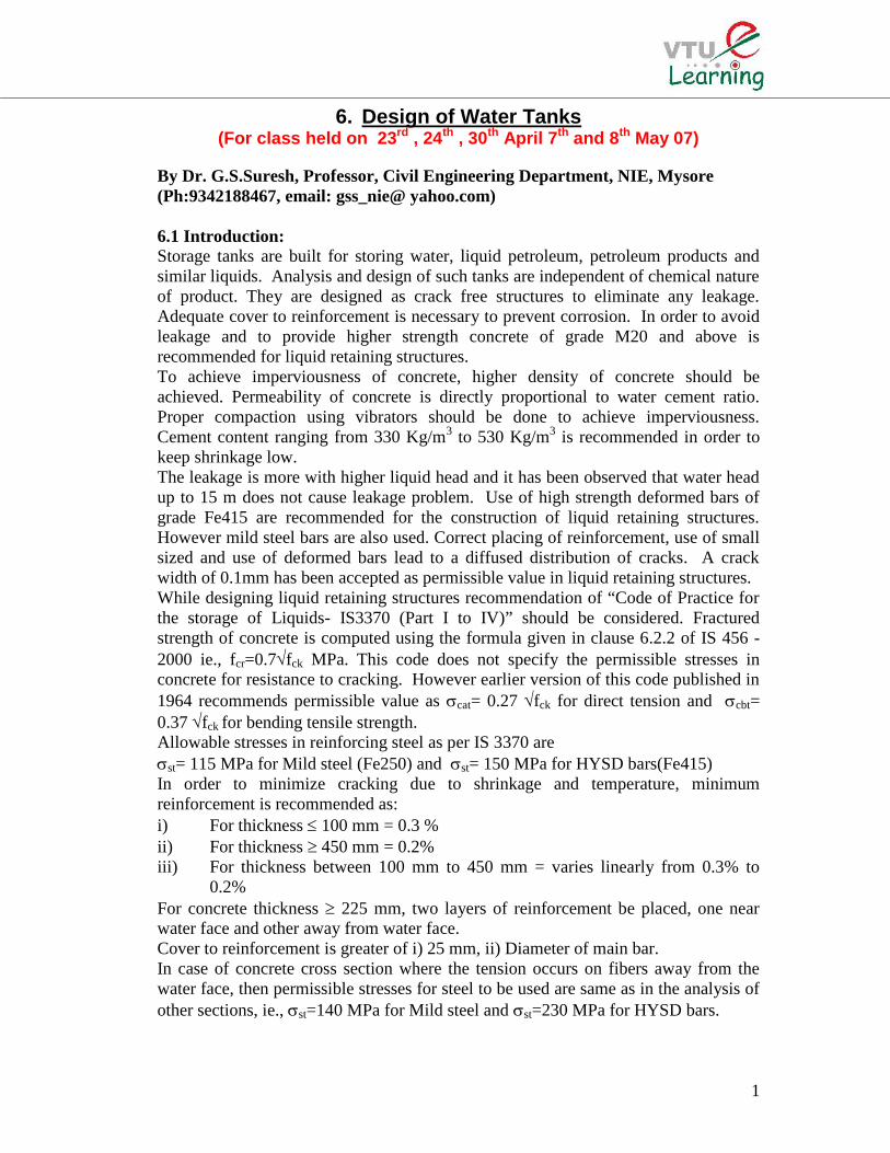
6.2 Introduction to Working Stress method:In this method the concrete and steel are assumed to be elastic. At the worstcombination of working loads, the stresses in materials are not exceeded beyondpermissible stresses. The permissible stresses are found by using suitable factors ofsafety to material strengths. Permissible stresses for different grades of concrete andsteel are given in Tables 21 and 22 respectively of IS456-2000.The modular ratio ‘m’ of composite material ie., RCC is defined as the ratio ofmodulus of elasticity of steel to modulus of elasticity of concrete. But the code
stipulate the value of ‘m asbc3
280m
, where bc is the permissible stress in concrete
in bending compression.To develop equation for moment of resistance of singly reinforced beams, the linearstrain and stress diagram are shown in Fig. 6.1
The neutral axis depth is obtained from strain diagram as
sst
ccbc
E/
E/
xd
x
=
st
cbcm
solving for x; kddm
mx
stcbc
cbc
where,
stcbc
cbc
m
mk , k is known as neutral axis constant
The lever arm z=d-x/3 = d-(kd/3)= d(1-k/3) = jd, where, j=1-k/3; j is known as leverarm constantC= ½ cbcbx; T= st Ast
Moment of resistance M= C z = T zConsider, M=C z = (½ cbcbx) jd = (½ cbcbkd) jd = (½ cbckj) bd2 = Qbal bd2
Where, Qbal is known as moment of resistance factor for balanced section.Now consider M= T z = st Ast jd;
c
cbcc E
x/3C
cbc
T
x
d
b
s
stst E
z
Section
StrainDiagram
StressDiagram
Fig. 6.1 Singly Reinforced Section
3
jd
MA
stst ; Let pt be the percentage of steel expressed as
st
cbc
st
sttbal
k50
bd
1
jd
M100
bd
A100p
Design constants for balanced section is given in table 6.1Table 6.1 Design constants
ConcreteGrade
SteelGrade
cbc st k j Qbal ptbal
M20Fe250 7 140 0.4 0.87 1.21 1.00Fe415 7 230 0.29 0.9 0.91 0.44
M25Fe250 8.5 140 0.4 0.87 1.48 0.68Fe415 8.5 230 0.29 0.9 1.1 0.533
6.3 Liquid Retaining Members subjected to axial tension only:When the member of a liquid retaining structure is subjected to axial tension only, themember is assumed to have sufficient reinforcement to resist all the tensile force andthe concrete is assumed to be uncracked.For analysis purpose 1m length of wall and thickness ‘t’ is considered. The tension inthe member is resisted only by steel and hence
stst
TA
and T 1000 t ct+(m-1)Ast st or
st
ct
ct
)1m(11000
Tt
Minimum thickness of the member required is tabulate in table 6.2Table 6.2 Minimum thickness of members under direct tension (Uncracked condition)
Grade ofconcrete
Thickness of members in mm for force T in NMild steel HYSD
M20 T/1377 T/1331M25 T/1465 T/1423M30 T/1682 T/1636
6.4 Liquid Retaining Members subjected to Bending Moment only:For the members subjected to BM only with the tension face in contact with water orfor the members of thickness less than 225 mm, the compressive stress and tensilestresses should not exceed the value given in IS 3370. For the member of thicknessmore than 225 mm and for the face away from the liquid, this condition need not besatisfied and higher stress in steel may be allowed. The bending analysis is done forcracked and uncracked condition.Cracked condition: The procedure of designing is same as in working stress methodexcept that the stresses in steel are reduced. The design coefficients for these reducedstresses in steel is given in Table 6.3
4
Table 6.3 Design constants for members in bending (Cracked condition)ConcreteGrade
SteelGrade
cbc st k j Qbal ptbal
For members less than 225 mm thickness and tension on liquid face
M20Fe250 7 115 0.445 0.851 1.33 1.36Fe415 7 150 0.384 0.872 1.17 0.98
For members more than 225 mm thickness and tension away from liquid face
M20Fe250 7 125 0.427 0.858 1.28 1.2Fe415 7 190 0.329 0.89 1.03 0.61
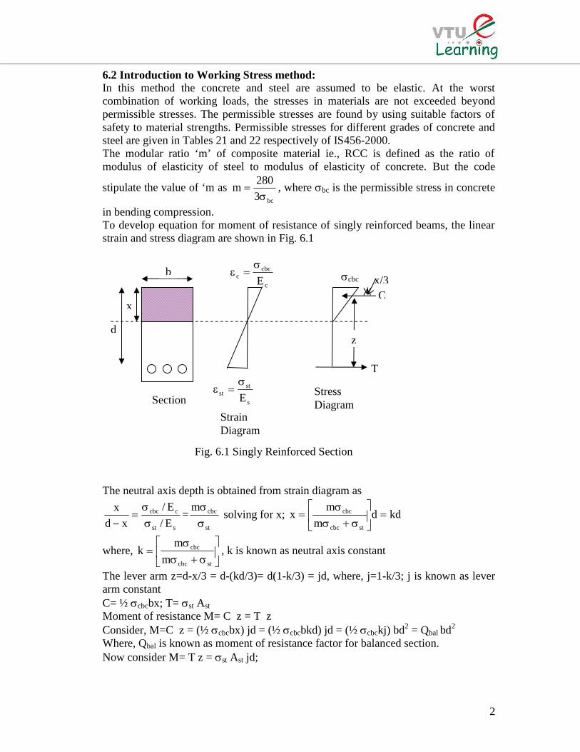
Uncracked condition: In this case, the whole section is assumed to resist the moment.Hence the maximum tensile stress in concrete should not be more than permissible value.The section is designed as a homogenous section.
Taking moments of transformed areas about NAb kD kD/2 = b (D-kD) (D-kD)/2 + (m-1) Ast (d-kD)Substituting Ast = pt bD /100 and simplifying
)1m(p2200
)1m(D
dp2100
kt
t
Moment of inertia Ixx=bD3/12 + bD (kD-D/2)2 + (m-1) Ast (d-kD)2
substituting Ast = pt bD /100 and simplifyingIxx=(1/3 – k(1-k)+(d/D-k)2 (m-1) pt/100)bD3
The moment of resistance may be expressed using Bernouli’s equation
)k1(DkDDI
M cbccb
xx
and)k1(D
IM xxcbt
cbt
cbc
kD
d
b
SectionStressDiagram
Fig. 6.1 Singly Reinforced Section
D
5
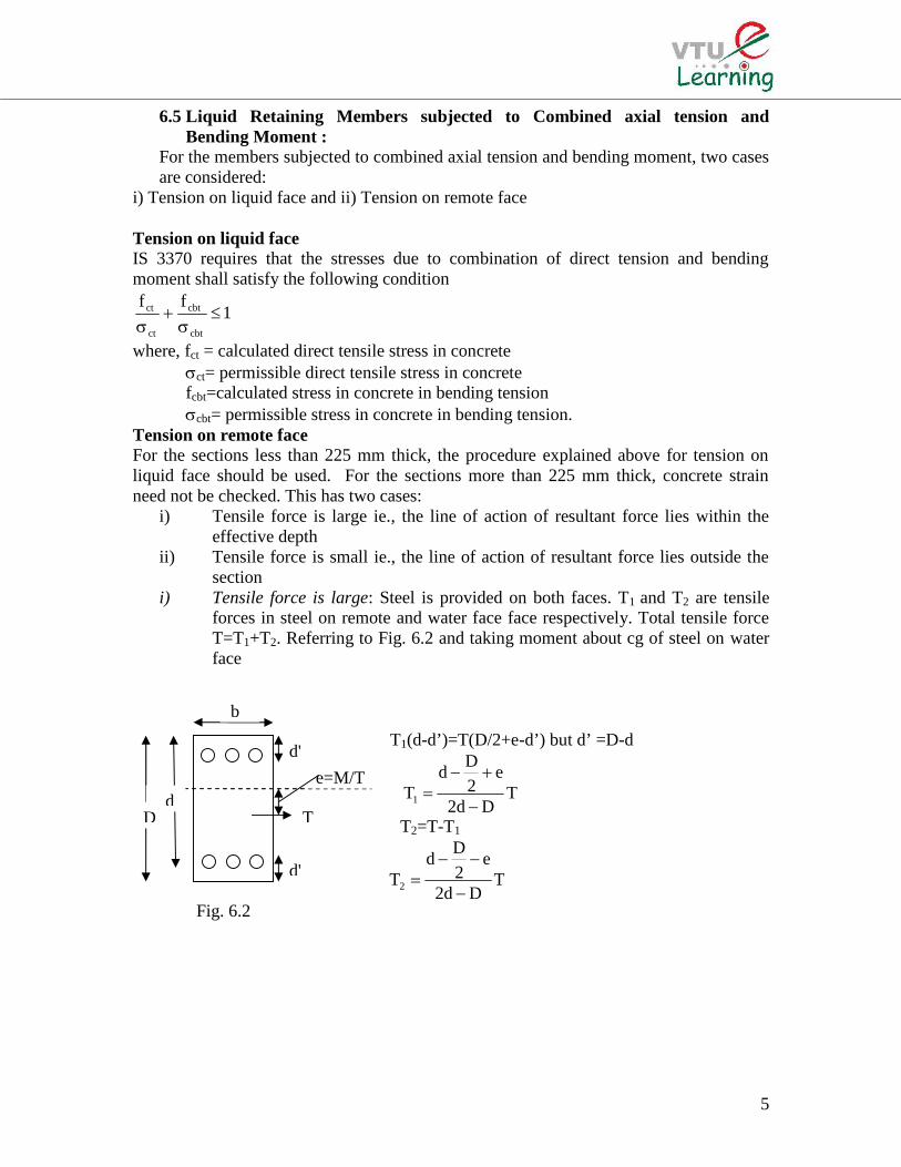
d'
b
Fig. 6.2
D
d'
dT
e=M/T
6.5 Liquid Retaining Members subjected to Combined axial tension andBending Moment :
For the members subjected to combined axial tension and bending moment, two casesare considered:
i) Tension on liquid face and ii) Tension on remote face
Tension on liquid faceIS 3370 requires that the stresses due to combination of direct tension and bendingmoment shall satisfy the following condition
1ff
cbt
cbt
ct
ct
where, fct = calculated direct tensile stress in concrete
ct= permissible direct tensile stress in concretefcbt=calculated stress in concrete in bending tensioncbt= permissible stress in concrete in bending tension.
Tension on remote faceFor the sections less than 225 mm thick, the procedure explained above for tension onliquid face should be used. For the sections more than 225 mm thick, concrete strainneed not be checked. This has two cases:
i) Tensile force is large ie., the line of action of resultant force lies within theeffective depth
ii) Tensile force is small ie., the line of action of resultant force lies outside thesection
i) Tensile force is large: Steel is provided on both faces. T1 and T2 are tensileforces in steel on remote and water face face respectively. Total tensile forceT=T1+T2. Referring to Fig. 6.2 and taking moment about cg of steel on waterface
T1(d-d’)=T(D/2+e-d’) but d’ =D-d
TDd2
e2
Dd
T1
T2=T-T1
TDd2
e2
Dd
T2
6
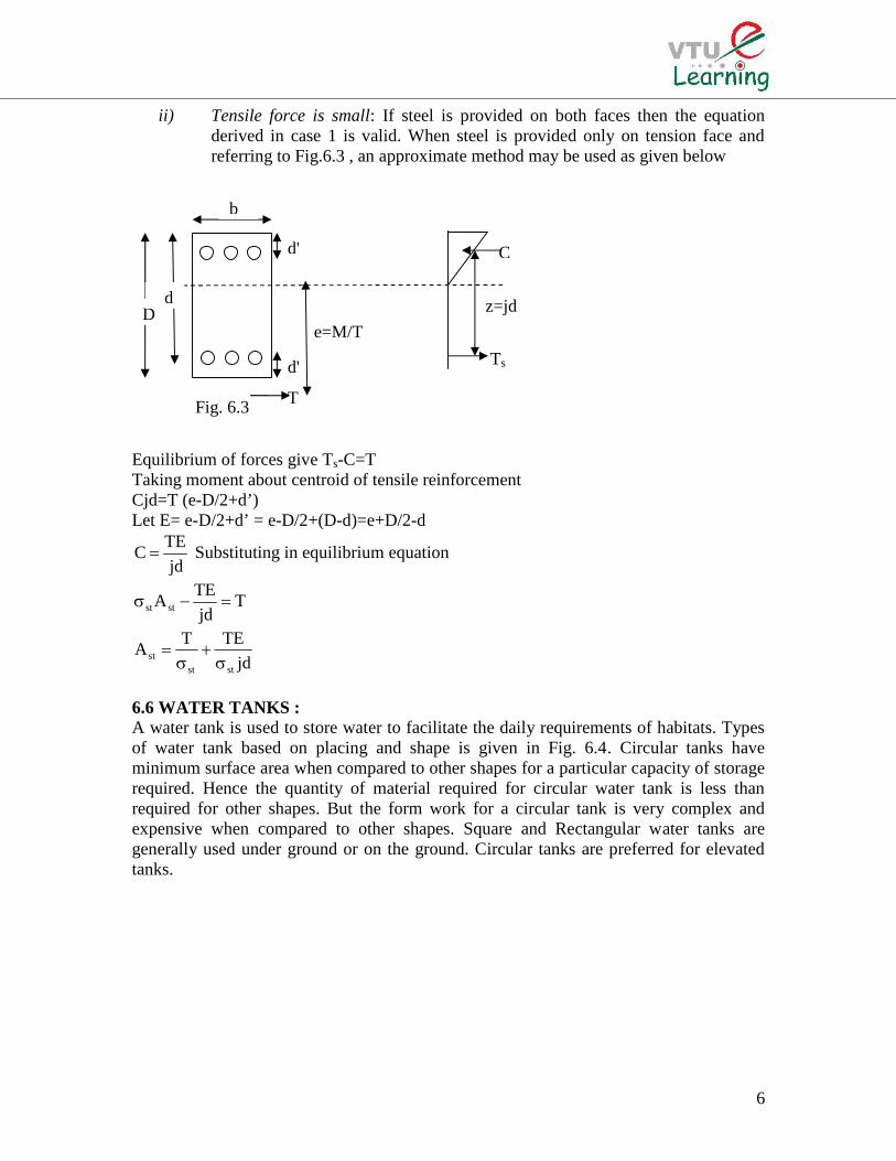
C
Ts
z=jd
e=M/T
T
d'
b
Fig. 6.3
D
d'
d
ii) Tensile force is small: If steel is provided on both faces then the equationderived in case 1 is valid. When steel is provided only on tension face andreferring to Fig.6.3 , an approximate method may be used as given below
Equilibrium of forces give Ts-C=TTaking moment about centroid of tensile reinforcementCjd=T (e-D/2+d’)Let E= e-D/2+d’ = e-D/2+(D-d)=e+D/2-d
jd
TEC Substituting in equilibrium equation
Tjd
TEAstst
jd
TETA
ststst
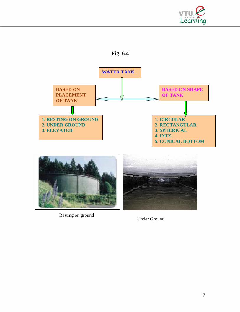
6.6 WATER TANKS :A water tank is used to store water to facilitate the daily requirements of habitats. Typesof water tank based on placing and shape is given in Fig. 6.4. Circular tanks haveminimum surface area when compared to other shapes for a particular capacity of storagerequired. Hence the quantity of material required for circular water tank is less thanrequired for other shapes. But the form work for a circular tank is very complex andexpensive when compared to other shapes. Square and Rectangular water tanks aregenerally used under ground or on the ground. Circular tanks are preferred for elevatedtanks.
7
Fig. 6.4
Resting on groundUnder Ground
WATER TANK
BASED ONPLACEMENTOF TANK
BASED ON SHAPEOF TANK
1. RESTING ON GROUND2. UNDER GROUND3. ELEVATED
1. CIRCULAR2. RECTANGULAR3. SPHERICAL4. INTZ5. CONICAL BOTTOM
8
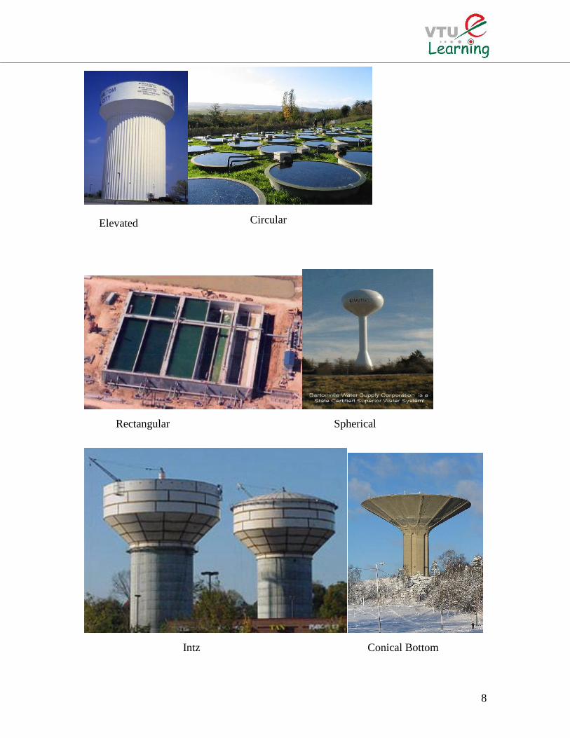
Elevated Circular
Rectangular Spherical
Intz Conical Bottom
9
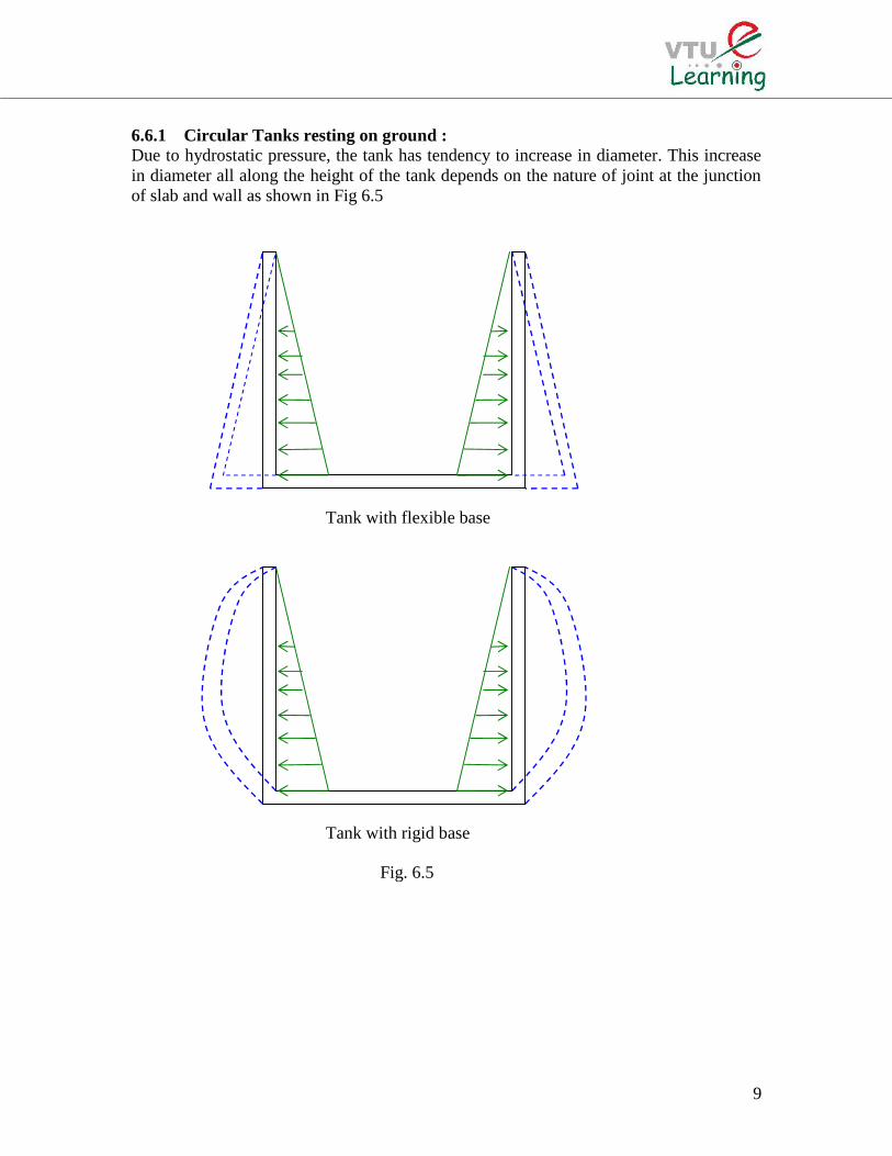
6.6.1 Circular Tanks resting on ground :Due to hydrostatic pressure, the tank has tendency to increase in diameter. This increasein diameter all along the height of the tank depends on the nature of joint at the junctionof slab and wall as shown in Fig 6.5
Tank with flexible base
Tank with rigid base
Fig. 6.5
10
T
T
When the joints at base are flexible, hydrostatic pressure induces maximum increase indiameter at base and no increase in diameter at top. This is due to fact that hydrostaticpressure varies linearly from zero at top and maximum at base. Deflected shape of thetank is shown in Fig. 6.5. When the joint at base is rigid, the base does not move. Thevertical wall deflects as shown in Fig. 6.5.6.6.1.1 Design of Circular Tanks resting on ground with flexible base:Maximum hoop tension in the wall is developed at the base. This tensile force T iscomputed by considering the tank as thin cylinder
2
DHT ; Quantity of reinforcement
required in form of hoop steel is computed
asstst
st
2/HDTA
or 0.3 % (minimum)
When the thickness of the wall is less than225 mm, the steel placed at centre. When thethickness exceeds 225mm, at each face Ast/2of steel as hoop reinforcement is provided
In order to provide tensile stress in concrete to be less to be less than permissible stress,the stress in concrete is computed using equation
ststcc A)1m(t1000
2/HD
A)1m(A
T
If c cat, where cat=0.27fck, then the
section is from cracking, otherwise the thickness has to be increased so that c is less thancat. While designing, the thickness of concrete wall can be estimated as t=30H+50 mm,where H is in meters. Distribution steel in the form of vertical bars are provided such thatminimum steel area requirement is satisfied. As base slab is resting on ground and nobending stresses are induced hence minimum steel distributed at bottom and the top areprovided
Design Problem:Design a circular water tank with flexible connection at base for a capacity of 4,00,000liters. The tank rests on a firm level ground. The height of tank including a free board of200 mm should not exceed 3.5m. The tank is open at top. Use M 20 concrete and Fe 415steel. Draw to a suitable scale:
i) Plan at baseii) Cross section through centre of tank.
Solution:Step 1: Dimension of tankDepth of water H=3.5 -0.2 = 3.3 mVolume V = 4,00,000/1000 = 400 m3
Area of tank A = 400/3.3 = 121.2 m2
Diameter of tank m42.12A4
D
13 m
11
The thickness is assumed as t = 30H+50=149 160 mmStep 2: Design of Vertical wall
Max hoop tension at bottom kN5.2142
133.310
2
DHT
Area of steel 23
ststst mm1430
150
105.214TTA
Minimum steel to be providedAst min=0.24%of area of concrete = 0.24x 1000x160/100 = 384 mm2
The steel required is more than the minimum requiredLet the diameter of the bar to be used be 16 mm, area of each bar =201 mm2
Spacing of 16 mm diameter bar=1430x 1000/201= 140.6 mm c/cProvide #16 @ 140 c/c as hoop tension steelStep 3: Check for tensile stressArea of steel provided Ast provided=201x1000/140 = 1436.16 mm2
Modular ratio m= 33.1373
280
3
280
cbc
Stress in concrete 23
stc N/mm2.1
1436)133.13(1601000
105.214
A)1m(t1000
T
Permissible stress cat=0.27fck= 1.2 N/mm2
Actual stress is equal to permissible stress, hence safe.Step 4: Curtailment of hoop steel:Quantity of steel required at 1m, 2m, and at top are tabulated. In this table the maximumspacing is taken an 3 x 160 = 480 mm
Height from top Hoop tensionT =HD/2 (kN)
Ast= T/st Spacing of #16mm c/c
2.3 m 149.5 996 2001.3 m 84.5 563.33 350Top 0 Min steel (384 mm2) 400
Step 5: Vertical reinforcement:For temperature and shrinkage distribution steel in the form of vertical reinforcement isprovided @ 0.24 % ie., Ast=384 mm2.Spacing of 10 mm diameter bar = 78.54x1000/384=204 mm c/c 200 mm c/c
Step 6: Tank floor:As the slab rests on firm ground, minimum steel @ 0.3 % is provided. Thickness of slabis assumed as 150 mm. 8 mm diameter bars at 200 c/c is provided in both directions atbottom and top of the slab.

12
13
6.6.1.2 Design of Circular Tanks resting on ground with rigid base:Due to fixity at base of wall, the upper part of the wall will have hoop tension and lowerpart bend like cantilever. For shallow tanks with large diameter, hoop stresses are verysmall and the wall act more like cantilever. For deep tanks of small diameter thecantilever action due to fixity at the base is small and the hoop action is predominant.The exact analysis of the tank to determine the portion of wall in which hoop tension ispredominant and the other portion in which cantilever action is predominant, is difficult.Simplified methods of analysis are
i) Reissner’s methodii) Carpenter’s simplified methodiii) Approximate methodiv) IS code method
Use of IS code method for analysis and design of circular water tank with rigid base isstudied in this course.IS code methodTables 9,10 and 11 of IS 3370 part IV gives coefficients for computing hoop tension,moment and shear for various values of H2/DtHoop tension, moment and shear is computed asT= coefficient ( wHD/2)M= coefficient (wH3)V= coefficient (wH2)Thickness of wall required is computed from BM consideration ie.,
Qb
Md
where,Q= ½ cbcjk
stcbc
cbc
m
mk
j=1-(k/3)b = 1000mm
Providing suitable cover, the over all thickness is then computed as t = d+cover.Area of reinforcement in the form of vertical bars on water face is computed as
jd
MA
stst . Area of hoop steel in the form of rings is computed as
st1st
TA
Distribution steel and vertical steel for outer face of wall is computed from minimumsteel consideration.Tensile stress computed from the following equation should be less than the permissiblestress for safe design
stc A)1m(t1000
T
and the permissible stress is 0.27 fck
Base slab thickness generally varies from 150mm to 250 mm and minimum steel isdistributed to top and bottom of slab.
14
Design Problem No.1:A cylindrical tank of capacity 7,00,000 liters is resting on good unyielding ground. Thedepth of tank is limited to 5m. A free board of 300 mm may be provided. The wall andthe base slab are cast integrally. Design the tank using M20 concrete and Fe415 gradesteel . Draw the following
i) Plan at baseii) Cross section through centre of tank.
Solution:Step 1: Dimension of tankH= 5-0.3 = 4.7 and volume V = 700 m3
A=700/4.7 = 148.94 m2
D= (4 x 148.94/) = 13.77 14 mStep 2: Analysis for hoop tension and bending momentOne meter width of the wall is considered and the thickness of the wall is estimated ast=30H+50 = 191 mm. The thickness of wall is assumed as 200 mm.
889.72.014
7.4
Dt
H 22
Referring to table 9 of IS3370 (part IV), the maximum coefficient for hooptension = 0.575Tmax=0.575 x 10 x 4.7 x 7 =189.175 kNReferring to table 10 of IS3370 (part IV), the maximum coefficient forbending moment = -0.0146 (produces tension on water side)Mmax= 0.0146 x 10 x 4.73=15.15 kN-m
Step 3: Design of section:For M20 concrete cbc=7, For Fe415 steel st=150 MPa and m=13.33 for M20 concreteand Fe415 steelThe design constants are:
39.0m
mk
stcbc
cbc
j=1-(k/3)=0.87Q= ½ cbcjk = 1.19Effective depth is calculated as Step 3: Design of section:For M20 concrete cbc=7, For Fe415 steel st=150 MPa and m=13.33 for M20 concreteand Fe415 steelThe design constants are:
39.0m
mk
stcbc
cbc
j=1-(k/3)=0.87Q= ½ cbcjk = 1.19
Effective depth is calculated as mm94.1121000x19.1
10x15.15
Qb
Md
6
15
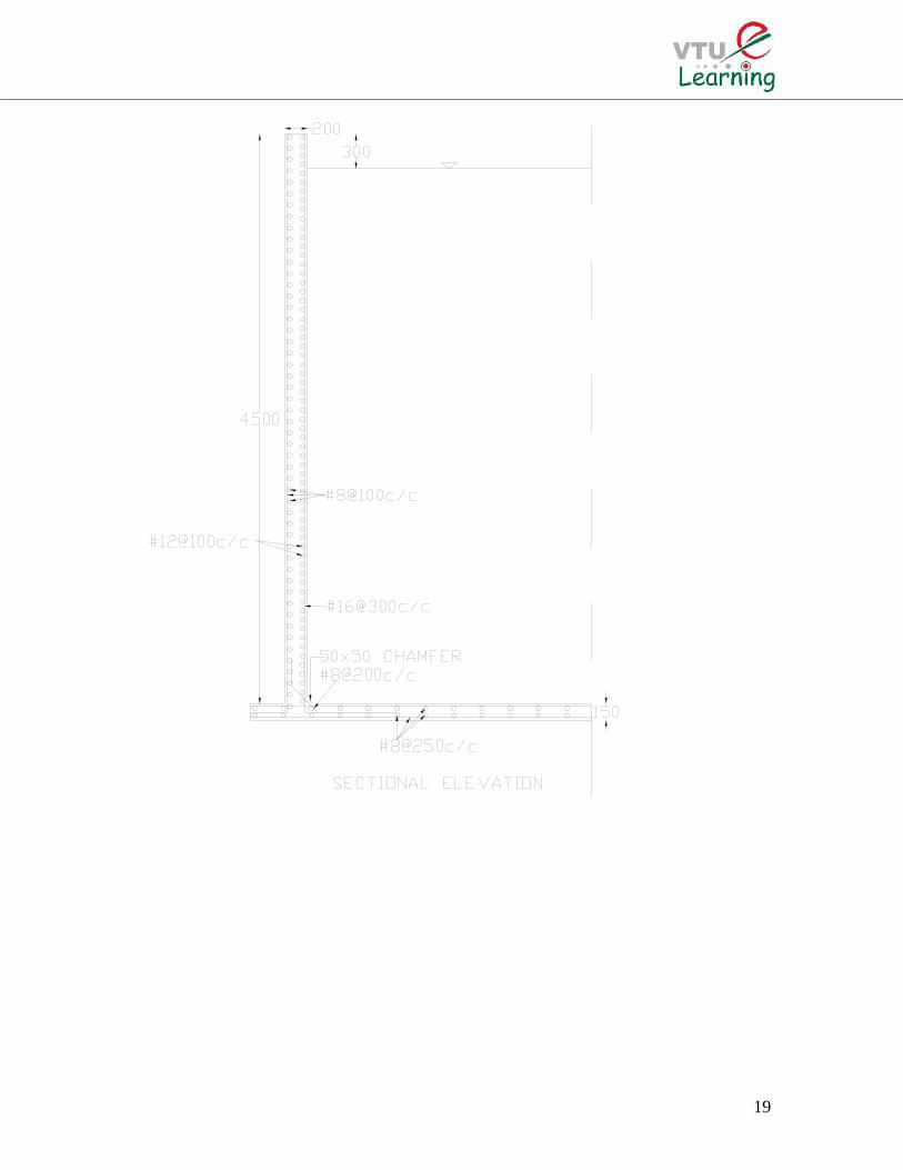
Let over all thickness be 200 mm with effective cover 33 mm dprovided=167 mm
26
stst mm16.695
167x87.0x150
10x15.15
jd
MA
Spacing of 16 mm diameter bar = c/mmc23.28916.695
1000x201 (Max spacing 3d=501mm)
Provide #16@275 c/c as vertical reinforcement on water face
Hoop steel: 23
st1st mm1261
150
10x275.189TA
Spacing of 12 mm diameter bar = c/mmc.891261
1000x113
Provide #12@80 c/c as hoop reinforcement on water face
Actual area of steel provided 2st mm5.1412
80
1000x113A
Step 4: Check for tensile stress:
23
stc mm/N87.0
5.1412x)133.13(200x1000
10x275.189
A)1m(t1000
T
Permissible stress = 0.27fck=1.2 N/mm2 > c Safe
Step 5: Distribution Steel:Minimum area of steel is 0.24% of concrete areaAst=(0.24/100) x1000 x 200 = 480 mm2
Spacing of 8 mm diameter bar = c/mmc.7.104480
1000x24.50
Provide #8 @ 100 c/c as vertical and horizontal distribution on the outer face.
Step 5: Base slab:The thickness of base slab shall be 150 mm. The base slab rests on firm ground, henceonly minimum reinforcement is provided.Ast=(0.24/100) x1000 x 150 = 360 mm2
Reinforcement for each face = 180 mm2
Spacing of 8 mm diameter bar = c/mmc.279180
1000x24.50
Provide #8 @ 250 c/c as vertical and horizontal distribution on the outer face.

16

17
Design Problem No.2:Design a circular water tank to hold 5,50,000 liters of water. Assume rigid joints betweenthe wall and base slab. Adopt M20 concrete and Fe 415 steel. Sketch details ofreinforcements.
Solution:Step 1: Dimension of tankVolume of tank V=550 m3
Assume H= 4.5A=550/4.5 = 122.22 m2
D= (4 x 122.22/) = 12.47 12.5 mStep 2: Analysis for hoop tension and bending momentOne meter width of the wall is considered and the thickness of the wall is estimated ast=30H+50 = 185 mm. The thickness of wall is assumed as 200 mm.
81.82.05.12
5.4
Dt
H 22
Referring to table 9 of IS3370 (part IV), the maximum coefficient for hooptension = 0.575Tmax=0.575 x 10 x 4.5 x 6.25 =161.72 kNReferring to table 10 of IS3370 (part IV), the maximum coefficient forbending moment = -0.0146 (produces tension on water side)Mmax= 0.0146 x 10 x 4.53=13.3 kN-m
Step 3: Design of section:For M20 concrete cbc=7, For Fe415 steel st=150 MPa and m=13.33 for M20 concreteand Fe415 steelThe design constants are:
39.0m
mk
stcbc
cbc
j=1-(k/3)=0.87Q= ½ cbcjk = 1.19
Effective depth is calculated as mm7.1051000x19.1
10x3.13
Qb
Md
6
Let over all thickness be 200 mm with effective cover 33 mm dprovided=167 mm
26
stst mm27.610
167x87.0x150
10x3.13
jd
MA
Spacing of 16 mm diameter bar = c/mmc36.32927.610
1000x201 (Max spacing 3d=501mm)
Provide #16@300 c/c as vertical reinforcement on water face
Hoop steel: 23
st1st mm13.1078
150
10x72.161TA
18
Spacing of 12 mm diameter bar = c/mmc10413.1078
1000x113
Provide #12@100 c/c as hoop reinforcement on water face
Actual area of steel provided 2st mm1130
100
1000x113A
Step 4: Check for tensile stress:
23
stc mm/N76.0
1130x)133.13(200x1000
10x72.161
A)1m(t1000
T
Permissible stress = 0.27fck=1.2 N/mm2 > c Safe
Step 5: Distribution Steel:Minimum area of steel is 0.24% of concrete areaAst=(0.24/100) x1000 x 200 = 480 mm2
Spacing of 8 mm diameter bar = c/mmc.7.104480
1000x24.50
Provide #8 @ 100 c/c as vertical and horizontal distribution on the outer face.
Step 5: Base slab:The thickness of base slab shall be 150 mm. The base slab rests on firm ground, henceonly minimum reinforcement is provided.Ast=(0.24/100) x1000 x 150 = 360 mm2
Reinforcement for each face = 180 mm2
Spacing of 8 mm diameter bar = c/mmc.279180
1000x24.50
Provide #8 @ 250 c/c as vertical and horizontal distribution on the outer face.
19
20
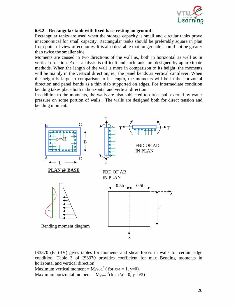
6.6.2 Rectangular tank with fixed base resting on ground :Rectangular tanks are used when the storage capacity is small and circular tanks proveuneconomical for small capacity. Rectangular tanks should be preferably square in planfrom point of view of economy. It is also desirable that longer side should not be greaterthan twice the smaller side.Moments are caused in two directions of the wall ie., both in horizontal as well as invertical direction. Exact analysis is difficult and such tanks are designed by approximatemethods. When the length of the wall is more in comparison to its height, the momentswill be mainly in the vertical direction, ie., the panel bends as vertical cantilever. Whenthe height is large in comparison to its length, the moments will be in the horizontaldirection and panel bends as a thin slab supported on edges. For intermediate conditionbending takes place both in horizontal and vertical direction.In addition to the moments, the walls are also subjected to direct pull exerted by waterpressure on some portion of walls. The walls are designed both for direct tension andbending moment.`
IS3370 (Part-IV) gives tables for moments and shear forces in walls for certain edgecondition. Table 3 of IS3370 provides coefficient for max Bending moments inhorizontal and vertical direction.Maximum vertical moment = Mxwa3 ( for x/a = 1, y=0)Maximum horizontal moment = Mywa3(for x/a = 0, y=b/2)
a-
+
TTCB
PLAN @ BASE
DA
p=H
TT
T
FBD OF ABIN PLAN
FBD OF ADIN PLAN
y
L
B
Bending moment diagram
0.5b 0.5b
x
21
Tension in short wall is computed as Ts=pL/2Tension in long wall TL=pB/2Horizontal steel is provided for net bending moment and direct tensile force
Ast=Ast1+Ast2;jd
'MA
st1st ; M’=Maximum horizontal bending moment – T x; x= d-D/2
Ast2=T/st
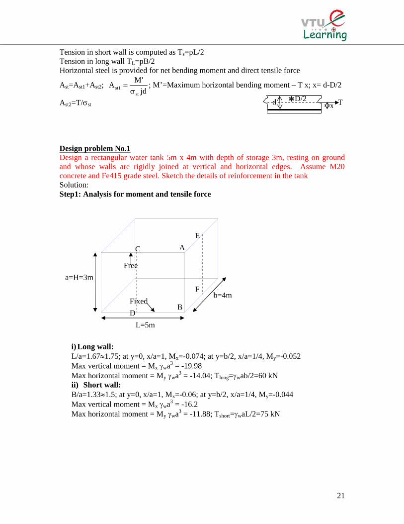
Design problem No.1Design a rectangular water tank 5m x 4m with depth of storage 3m, resting on groundand whose walls are rigidly joined at vertical and horizontal edges. Assume M20concrete and Fe415 grade steel. Sketch the details of reinforcement in the tankSolution:Step1: Analysis for moment and tensile force
i) Long wall:L/a=1.671.75; at y=0, x/a=1, Mx=-0.074; at y=b/2, x/a=1/4, My=-0.052Max vertical moment = Mx wa3 = -19.98Max horizontal moment = My wa3 = -14.04; Tlong=wab/2=60 kNii) Short wall:B/a=1.331.5; at y=0, x/a=1, Mx=-0.06; at y=b/2, x/a=1/4, My=-0.044Max vertical moment = Mx wa3 = -16.2Max horizontal moment = My wa3 = -11.88; Tshort=waL/2=75 kN
E
B
A
F
D
C
Free
a=H=3m
b=4m
L=5m
Fixed
xD/2d T
22
CA
11.88
14.4
B
Step2: Design constantscbc=7 MPa, st=150 MPa, m=13.33
38.0m
mk
stcbc
cbc
j=1-(k/3)=0.87Q= ½ cbcjk = 1.15Step3: Design for vertical momentFor vertical moment, the maximum bending moment from long and short wall(Mmax)x=-19.98 kN-m
mm8.1311000x15.1
10x98.19
Qb
Md
6
Assuming effective cover as 33mm, the thickness of wall ist=131.88+33=164.8 mm170 mmdprovided=170-33=137mm
26
stst mm54.1117
137x87.0x150
10x98.19
jd
MA
Spacing of 12 mm diameter bar = c/mmc2.10154.1117
1000x113 (Max spacing 3d=411mm)
Provide #12 @ 100 mm c/cDistribution steelMinimum area of steel is 0.24% of concrete areaAst=(0.24/100) x1000 x 170 = 408 mm2
Spacing of 8 mm diameter bar = c/mmc19.123408
1000x24.50
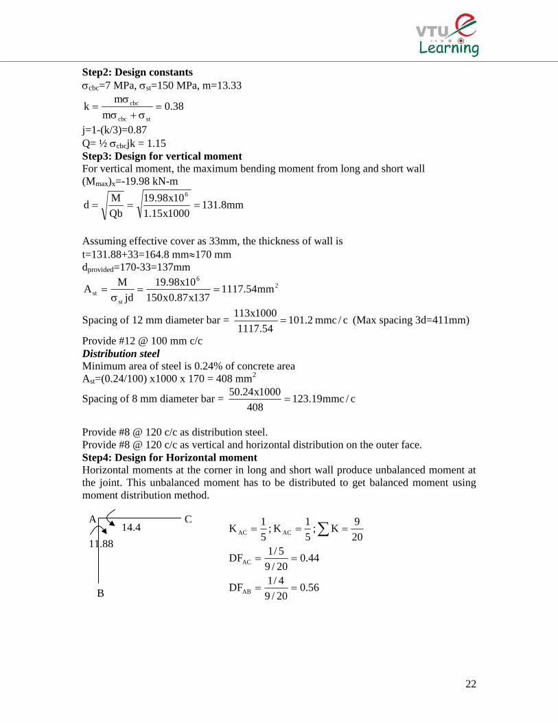
Provide #8 @ 120 c/c as distribution steel.Provide #8 @ 120 c/c as vertical and horizontal distribution on the outer face.Step4: Design for Horizontal momentHorizontal moments at the corner in long and short wall produce unbalanced moment atthe joint. This unbalanced moment has to be distributed to get balanced moment usingmoment distribution method.
56.020/9
4/1DF
44.020/9
5/1DF
20
9K;
5
1K;
5
1K
AB
AC
ACAC

23
Moment distribution TableJoint A
Member AC ABDF 0.44 0.56FEM -14 11.88Distribution 0.9328 1.1872Final Moment -13.0672 13.0672The tension in the wall is computed by considering the section at height H1 from the base.Where, H1 is greater of i) H/4, ii) 1m, ie., i) 3/4=0.75, ii) 1m; H1= 1mDepth of water h=H-H1=3-1-2m; p=wh=10 x 2= 20 kN/m2
Tension in short wall Ts=pL/2=50 kNTension in long wall TL=pB/2= 40 kNNet bending moment M’=M-Tx, where, x= d-D/2=137-(170/2)=52mmM’=13.0672-50 x 0.052=10.4672 kN-m
26
1st mm46.585137x87.0x150
10x4672.10A
23
2st mm33.333150
10x50A
Ast=Ast1+Ast2=918.79 mm2
Spacing of 12 mm diameter bar = c/mmc12374.918
1000x113 (Max spacing 3d=411mm)
Provide #12@120 mm c/c at corners
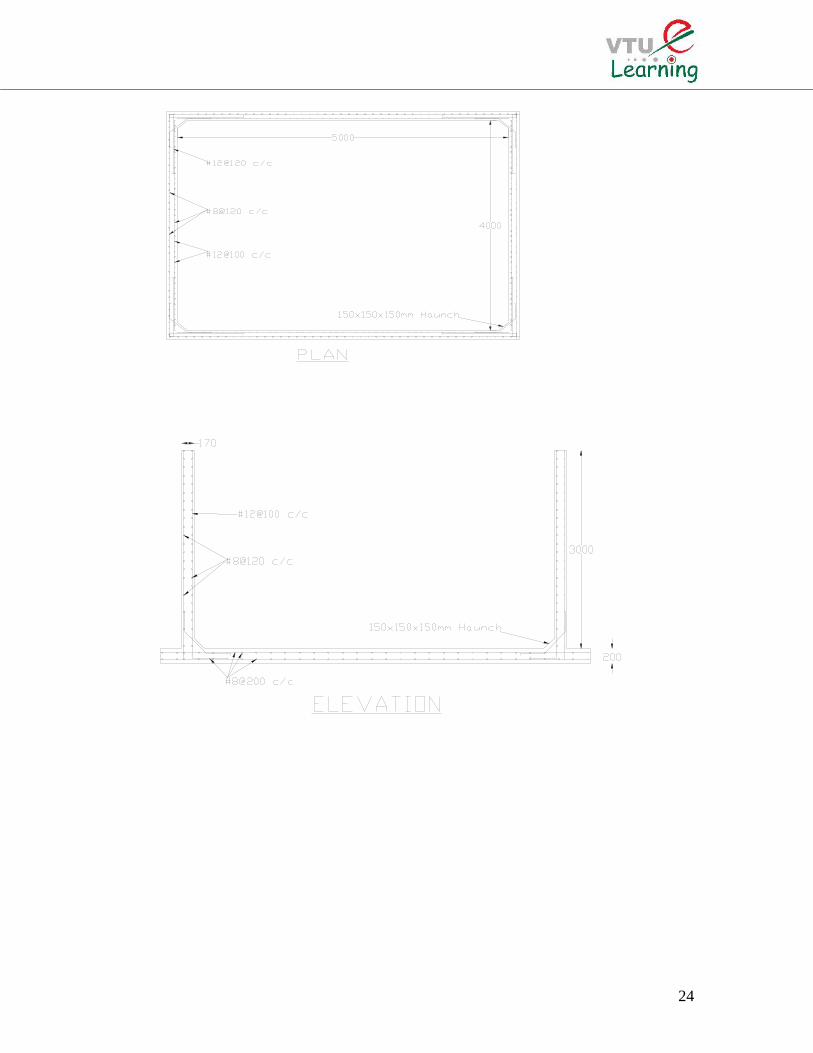
Step5: Base Slab:The slab is resting on firm ground. Hence nominal thickness and reinforcement isprovided. The thickness of slab is assumed to be 200 mm and 0.24% reinforcement isprovided in the form of #8 @ 200 c/c. at top and bottomA haunch of 150 x 150 x 150 mm size is provided at all corners
24