6. calorimetry - university of illinois urbana-champaign
TRANSCRIPT

6. Calorimetry
213533
Introduction to Calorimeter R&D To explore the uncharted territory of the Electroweak symmetry breaking energies, identification of Z, W and Higgs from their respective reconstructed decays is critical. This requires good lepton identification and very good jet energy resolution so that reconstructed jet-jet energies can be accurately measured. Dijet mass must be measured to a precision of ~3 GeV or, in terms of jet energy resolution, ( ) 0.3E Eσ ≈ (E in GeV). [52] The most important aspect of the calorimeter is to provide accurate measurements of the four-momenta of charged and neutral particles, individually and in jets. In the present parlance of calorimetry, this is best achieved by a Particle Flow algorithm in three dimensions. [53] The Particle Flow (or Energy Flow) Algorithm consists of following the tracks measured by the tracking detector into the calorimeter and measuring their respective energy deposits. These particles, which typically carry ~60% of a jet’s total energy, are measured with much higher precision by the magnetized inner tracker. The electromagnetic calorimeter (ECal) is used to measure EM showers, carrying on average ~25% of jet energy, with a resolution of ( ) 0.15E Eσ ≈ . This way, even though the energy resolution of the hadron calorimeter (HCal) for single hadrons may be no better than ( ) 0.6E Eσ ≈ , a net jet energy resolution of ( ) 0.3E Eσ ≈ is achievable by using the HCal to measure only the neutral hadrons, typically carrying merely ~11% of the total jet energy. Even with the component resolutions given here, the estimated jet resolution (0.3 here) is dominated by limitations of pattern recognition. Hence, the role of simulation and algorithm development is crucial. If realized, a detector for the LC will likely be the first with a calorimeter designed specifically for Particle Flow Algorithms. [54] It will be a challenge to develop algorithms under the unique conditions and constraints of the new facility. These will in turn drive the technology and design choices not only for the calorimeter, but for the inner tracker and the muon systems as well. For the calorimeter to be able to track and isolate charged particles in a jet while staying within a realistic budget, some features favored by traditional algorithms of sampling calorimetry may have to be sacrificed to gain 3-D tracking or imaging capabilities in the calorimeter. Particularly for the hadronic calorimeter, collecting a large number of hits with good position resolution will be more important than estimating the amount of energy associated with each hit. The current favorite designs for the SiD and Large Detector calorimeters have ~30 layers of ≤ 1 cm2 cells totaling ~30 radiation lengths in the ECal and ~40 layers of 1-10 cm2 cells in the Hcal. [55, 56] The Particle Flow scheme clearly requires a highly segmented calorimeter, both laterally and longitudinally. In principle, once the energy flow is fully accomplished, the long-coveted similar response to electrons and hadrons, namely, e/h ~ 1, should not be necessary, since energy deposited by each particle will be measured individually. However, to what extent this can be accomplished needs to be tested both by realistic simulations, and in beam tests.
214534
The considerations of cost and the technological challenge in satisfying the desire of having the entire calorimeter immersed in a 4-5 T magnetic field limit the radius of the calorimeter in the more popular designs. While a finely segmented calorimeter will aid muon measurements, the muon system may be required to serve as a “tail-catcher” for parts of jets leaking through the relatively thin calorimeter. Several competing technologies have been proposed and are being investigated under a worldwide collaborative effort. [57] Possible alternatives for the ECal include Si-W, Scintillator-W, or Scintillator-Pb. Plastic scintillators, Resistive Plate Chambers (RPC), and Gas Electron Multipliers (GEM) are all candidates for possible active media for the HCal. Hybrids employing multiple technologies are also possible for both the ECal and the HCal. UCLC and LCRD proposals aim to study these options, with all groups working in close collaboration. Hardware development must proceed in tandem, and in close cooperation with simulation studies. The design optimization must begin with simulation, while data from test-beam studies of the prototypes will help fine-tune the parameters of the simulation. Development of algorithms and extensive studies of a multitude of physics scenarios are key to designing the detector and charting the physics program. While every group interested in a specific detector technology accepts the responsibility of testing it in simulation, the overall plan involves much more. A flexible yet powerful software environment is required to generate millions of Monte Carlo (MC) events under various scenarios both within and beyond the Standard Model, simulate detector response to those under different options, reconstruct the signatures, tune algorithms, and parametrize detector response for very large volumes of MC events for which full detector simulation is not feasible. Several university groups, including some primarily involved in calorimetry, plan to contribute to the common infrastructure, support, and MC production service for the entire LC community. Increasingly, this effort is converging toward a global unification. Technical and fiscal considerations favor international collaboration in the planning and execution of beam tests as well. Recently, an international calorimeter effort has led to a formal test beam planning document for FNAL. [58]
References [52] J. C. Brient, H. Videau, Calorimetry at the future e+e- linear collider, hep-ex/0202004, and references therein, The American Research on LC Calorimetry http://www.slac.stanford.edu/ xorg/lcd/calorimeter/, and a collection of Calorimetry-related talks given at various LC workshops http://www.slac.stanford.edu/xorg/lcd/calorimeter/talks/cal_ talks.html, The CALICE project http://polywww.in2p3.fr/flc/calice.html and European research on LC Calorimetry http://polywww.in2p3.fr/flc/calice_publi. html, The Asian Research on LC Calorimetry http://www-jlc.kek.jp/subg/cal/. [53] P.Gay, Energy Flow with high-granularity calorimeters, LCW 2000, Fermilab, Oct. 2000. http://www-lc.fnal.gov/lcws2000, http://www-sldnt.slac.stanford.edu/nld/meetings/2000/20001010/ Calorimeter%20Clustering.pdf.
215535

[54] Worldwide Calorimeter Activities of the International Linear Collider Detector R&D http:// www-jlc.kek.jp/subg/cal/WWCAL/index.html. [55] Linear Collider Physics Resource Book for Snowmass 2001, American Linear Collider Working Group, BNL-52627, CLNS 01/1729, FERMILAB-Pub-01/058-E, LBNL-47813, SLAC-R-570, UCRL-ID-143810-DR, LC-REV-2001-074-US, hep-ex/0106058 http://www-sldnt.slac. stanford.edu/snowmass/OrangeBook/index.html. [56] Physics at an e+e- collider, R. D. Heuer, D. Miller, F. Richard, P. Zerwas, TESLA Technical Design Report, Part III, hep-ph/0106315 http://tesla.desy.de/new_pages/TDR_CD/ PartIII/physic.html. [57] Reports presented at the Cornell workshop of the ALCPG, July 2003, http://nicadd.niu.edu/ ˜dhiman/lc-cal/cornell03/cal_agenda.html, LC Calorimetry summary presented at the Cornell workshop of the ALCPG, July 2003, http://www.lns.cornell.edu/public/ LC/workshop/talks/Chakraborty_calsummary.ppt. [58] Fermilab Technical Memo, FNAL-TM-2291, February, 2005.
216536
Contents
6. Calorimetry: 533 Overview and contents.....................................................................................................534 6.1 Design and Prototyping of a Scintillator-based Semi-Digital Hadron Calorimeter (Vishnu Zutshi: renewal) .................................................................................................538 6.2 Calorimetry R&D at Colorado: Progress Report of Work in 2004 and Proposed Work for 2005, 2006, 2007 (Uriel Nauenberg: renewal)...........................................................549 6.4 Particle Flow Studies with the Silicon Detector (SiD) at the International Linear Collider (ILC) (Usha Mallik: renewal) ............................................................................566 6.5 Development of a silicon-tungsten test module for an electromagnetic calorimeter (Raymond Frey: renewal) ................................................................................................581 6.6 Digital Hadron Calorimetry for the Linear Collider using GEM based Technology (Andy White: renewal) ....................................................................................................591 6.9 Development of Particle-Flow Algorithms and Simulation Software for the ILC Detector(s) (Dhiman Chakraborty: renewal) ...................................................................602 6.10 Investigation of ECAL Concepts Designed for Particle Flow (Graham Wilson: new proposal) ..........................................................................................................................613 6.14 Construction of a Prototype Hadronic Calorimeter with Digital Readout (José Repond: new proposal) ....................................................................................................624 6.16 Dual-Readout Calorimetry for the ILC (Richard Wigmans: new proposal)...........634 6.17 Ultimate Hadron Calorimetry (Richard Wigmans: new proposal) .........................644
537

6.1
6.1
Calorimetry
6.1: Design and Prototyping of a Scintillator-based Semi-Digital Hadron
Calorimeter
(renewal)
Calorimetry
Contact person Vishnu Zutshi
[email protected] (815) 753-3080
Institution(s)
University of Colorado DESY
Fermilab ITEP NIU Pavia
Funds awarded (DOE)
FY04 award: 50,000
New funds requested FY05 request: 88,400
FY06 request: 176,700 FY07 request: 175,400
218538
Proposal to DOE/NSF for ILC Detector R&D
February 22, 2005
Proposal Name
Design and Prototyping of a Scintillator-based Semi-Digital Hadron Calorimeter.
Classification (accelerator/detector: subsystem)
Calorimeter: Hadron Calorimeter.
Personnel and Institution(s) requesting funding
D. Beznosko, G. Blazey, D. Chakraborty, A. Dyshkant, K. Francis, V. Rykalin, V. Zutshi.Northern Illinois Center for Accelerator and Detector Development/ Northern Illinois Uni-versity.
Collaborators
F. Sefkow et. al, Deutsches Elektronen-Synchrotron, Hamburg,S. Hansen et. al, Fermi National Accelerator Laboratory, Batavia,M. Danilov et. al, Institute of Theoretical and Experimental Physics, Moscow,U. Nauenberg et. al, University of Colorado, Boulder,G. Introzzi et. al, University of Pavia,The CALICE Collaboration.
Project Leader
(815)753-3080
Project Overview
The Northern Illinois University(NIU)/Northern Illinois Center for Accelerator and Detec-tor Development (NICADD) [1] group is interested in calorimeter R&D for the proposedLinear Collider. We propose to develop, in simulation and in prototype, designs for ahadron calorimeter (HCal) optimized for jet energy measurement using particle-flow algo-rithms (PFAs). Software simulations/algorithm development and hardware prototyping areenvisaged as the two main components of our efforts. This proposal addresses the secondcomponent while the first is the subject of a separate proposal. The end goal of this research
219539

project will be the development of reliable performance and cost estimates for scintillator-based hadron calorimeter options suited for, but not limited to, an e+e− linear collider. Thiswill be achieved by the construction and operation of a prototype in a hadron test beam.
It is clear that for the Linear Collider to fulfill its physics charter multi-jet final states willhave to be exceptionally well measured. In particular, superior resolutions in jet (30%/
√
E orbetter) and missing energy measurements will be critical for discovery and characterizationof the new physics as well as for precision tests of the Standard Model (SM). The mostpromising means to achieving such unprecedented resolutions at the next linear collider isthrough particle-flow algorithms [2] which require fine lateral and longitudinal segmentationof the calorimeter to individually reconstruct the showers constituting a jet. This approachallows one to make optimal use of the information available in the event: tracker momentafor charged hadrons and calorimetric energy measurements for photons and neutral hadrons.
The NIU team has been investigating a finely-segmented scintillator-based hadron calorimeterfor some time now. This option capitalizes on the marriage of proven detection techniques withnovel photodetector devices. Absence of fluids/gases and very high voltages inside the detectoraids longevity and operational stability. The main challenge for a scintillator-based hadroncalorimeter is the architecture and cost of converting light, from a large number of channels,to electrical signal. Our studies demonstrate that small cells (6-10 cm2) with embeddedSilicon Photomultipliers (SiPMs)/Metal Resistive Semiconductor (MRS) photodetectors offerthe most promise in tackling this issue. The in situ use of these photodetectors opens thedoors to integration of the full readout chain to an extent that makes a multi-million channelscintillator calorimeter entirely plausible. Also, in large quantities the devices are expected tocost a few dollars per channel making the construction of a full-scale detector instrumentedwith these photo-diodes financially feasible.
The very large number of readout channels can still pose a significant challenge in the formof complexity and cost of signal processing and data acquisition. Reducing the dynamicrange of the readout is a potential solution. Monte Carlo studies have shown that this isindeed a promising possibility as scintillator cells with an area in the 6-10 cm2 range are goodcandidates for one (digital) or two-bit (semi-digital) readout (see Fig. 1) where the lowestthreshold is set so as to detect the passage of a minimum ionizing particle. Performanceof PFAs on scintillator hadron calorimeter Monte Carlo’s with a minimum of amplitudeinformation in the form of thresholds also looks very competitive [3]. Thus fabrication ofcheap and compact electronics with just a few thresholds (three in the case of a 2-bit readout)which will deliver the required performance is a realistic possibility for a scintillator hadroncalorimeter.
In these tasks we have been coordinating our efforts with European groups pursuing similarinterests. This interaction takes place under the umbrella of the CALICE collaboration[4] which bands together universities and labs, interested in developing calorimeters for theLinear Collider, from all over the world. We are the only group in the United States, activelyinvestigating the promising option of a scintillator-based hadron calorimeter.
Results of Prior Research
To date we have received two grants for work related to the project described here. Theproject titled “Design and Prototyping of a Scintillator-based Digital Hadron Calorimeter”was initially submitted as part of the UCLC proposal to NSF in 2003. We were instructedto resubmit, without change in scope, in 2004. The 2003 submission resulted in a $11K NSF
220540
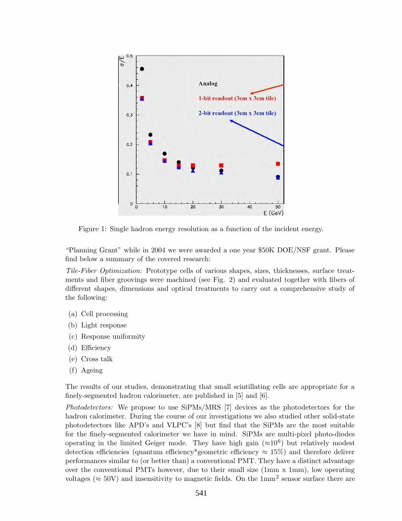
Figure 1: Single hadron energy resolution as a function of the incident energy.
“Planning Grant” while in 2004 we were awarded a one year $50K DOE/NSF grant. Pleasefind below a summary of the covered research:
Tile-Fiber Optimization: Prototype cells of various shapes, sizes, thicknesses, surface treat-ments and fiber groovings were machined (see Fig. 2) and evaluated together with fibers ofdifferent shapes, dimensions and optical treatments to carry out a comprehensive study ofthe following:
(a) Cell processing
(b) Light response
(c) Response uniformity
(d) Efficiency
(e) Cross talk
(f) Ageing
The results of our studies, demonstrating that small scintillating cells are appropriate for afinely-segmented hadron calorimeter, are published in [5] and [6].
Photodetectors: We propose to use SiPMs/MRS [7] devices as the photodetectors for thehadron calorimeter. During the course of our investigations we also studied other solid-statephotodetectors like APD’s and VLPC’s [8] but find that the SiPMs are the most suitablefor the finely-segmented calorimeter we have in mind. SiPMs are multi-pixel photo-diodesoperating in the limited Geiger mode. They have high gain (≈106) but relatively modestdetection efficiencies (quantum efficiency*geometric efficiency ≈ 15%) and therefore deliverperformances similar to (or better than) a conventional PMT. They have a distinct advantageover the conventional PMTs however, due to their small size (1mm x 1mm), low operatingvoltages (≈ 50V) and insensitivity to magnetic fields. On the 1mm2 sensor surface there are
221541
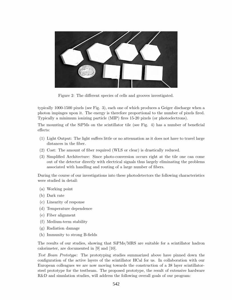
Figure 2: The different species of cells and grooves investigated.
typically 1000-1500 pixels (see Fig. 3), each one of which produces a Geiger discharge when aphoton impinges upon it. The energy is therefore proportional to the number of pixels fired.Typically a minimum ionizing particle (MIP) fires 15-20 pixels (or photoelectrons).
The mounting of the SiPMs on the scintillator tile (see Fig. 4) has a number of beneficialeffects:
(1) Light Output: The light suffers little or no attenuation as it does not have to travel largedistances in the fiber.
(2) Cost: The amount of fiber required (WLS or clear) is drastically reduced.
(3) Simplified Architecture: Since photo-conversion occurs right at the tile one can comeout of the detector directly with electrical signals thus largely eliminating the problemsassociated with handling and routing of a large number of fibers.
During the course of our investigations into these photodetectors the following characteristicswere studied in detail:
(a) Working point
(b) Dark rate
(c) Linearity of response
(d) Temperature dependence
(e) Fiber alignment
(f) Medium-term stability
(g) Radiation damage
(h) Immunity to strong B-fields
The results of our studies, showing that SiPMs/MRS are suitable for a scintillator hadroncalorimeter, are documented in [9] and [10].
Test Beam Prototype: The prototyping studies summarized above have pinned down theconfiguration of the active layers of the scintillator HCal for us. In collaboration with ourEuropean colleagues we are now moving towards the construction of a 38 layer scintillator-steel prototype for the testbeam. The proposed prototype, the result of extensive hardwareR&D and simulation studies, will address the following overall goals of our program:
222542

Figure 3: Pixellated surface of the SiPM sensor (left) and single photoelectron separation observedwith a SiPM (right).
Figure 4: The SiPM sensor mated with a 1mm WLS fiber and embedded in a 3cm x 3cm tile.
223543

Figure 5: Prototype geometry.
(a) Technology demonstration
(b) Exploration of the full range of readout from purely digital to fully analog
(c) Validation of hadron shower models in MC
(d) PFA development
The active layers of the prototype consist of 5mm thick scintillator tiles sandwiched between2cm thick steel absorber plates mounted on a movable table. In reality the absorber is splitinto three parts: 1.6cm absorber plate and two 0.2cm thick top and bottom skins of the“cassette” which houses the tiles. Each tile comes with its own 1mm diameter WLS fibermated to a SiPM embedded in it. The tiles come in three granularities: 3cm x 3cm, 6cm x6cm and 12cm x 12cm (see Fig. 5). The 3cm x 3cm cells form the inner core for thirty ofthe 38 layers while for the last eight layers only the coarser granularity cells are used. Thegranularity of the prototype has been optimized to achieve the goals listed above within areasonable budget. As the initial proponents of the finer granularity we are responsible forthe instrumentation of two-thirds (i.e. 20 layers) of the inner core. A 1mm thick co-axialcable runs from each photodetector to a charge integrating amplifier channel. This singleco-axial cable carries both the bias (on its shield) and signal (on its core). The cables aresupported on a G-10 plate which also has the reflective VM2000 glued to its tile-facing side.
Planned R&D
Prototype Operation: The scintillator hcal prototype will be exposed to a hadron test beamat Fermilab during the 2005-2007 period [11]. Hadrons in the momentum range 1-50 GeV areof interest. We propose to collect O(106) events per setting (energy, angle and particle type)for a total of ≈ 108 events. With ≈ 10K channels, the prototype is comparable in channelcount to the full calorimetric systems of some of the current collider experiments. Thus alarge investment in manpower and resources will be required. Our expertise and locationimplies that we will be playing a major role in the assembly, commissioning and operationof the prototype. Already one of us (VZ) has been named as one of the two ’ExperimentalContacts’ for the full ILC calorimeter test beam program. Substantial amount of our resourceswill also be required to calibrate and analyze the data being collected.
The operation of the scintillator-based hadron calorimeter prototype will deliver a wealth ofinformation. It is however clear that R&D will need to continue in parallel to carry the design
224544
forward and optimize it for its realization in an ILC detector. The 2-3 year LC test beamprogram will permit us to make incremental changes to the initial design which can then betested in the beam without having to assemble an entirely new device. In this regard the twomajor areas of concentration will be:
Electronics Development: A detector consisting of a few million channels requires a highdegree of integration. The small size, low bias and magnetic field immunity of the SiPMs hasalready allowed us to take the first step towards this goal. The photo-conversion occurs rightat the tile thus integrating the light transport and conversion functions on the tile itself. Thenext logical step is to bring an equivalent level of integration to the electrical signal path.While individual cables per tile are feasible for the prototype containing a few thousandchannels, they are not a viable option for a device with a few million channels. Our objectiveis the design and fabrication of a readout system with the required mechanical and electronicsintegration such that data from many tiles could be sent off the detector on a few conductors.The strategy is to have a PC board inside the detector which will connect directly to theSiPMs and carry the necessary electronics and signal/bias traces. The goal is to have robustand cheap electronics with the following functionality:
(a) Preamplification (gain of 10-20) .
(b) Multiple thresholds (cascading discriminators or time over base are possible options).
(c) Good time resolution.
(d) Electronic charge injection.
(e) Temperature monitoring.
For the full detector the most economical solution will be a custom ASIC which encompassesall of the above mentioned functionalities. For our R&D studies however we will be interestedin fabricating a prototype system of 500-1000 channels (10% of the channel count for the testbeam hadron calorimeter prototype) with discrete elements. This will help us identify andsolve electrical and mechanical issues associated with such a design at a fraction of the costrequired to develop an ASIC. It will be fairly straightforward to test a prototype of thissystem with the current hadron calorimeter prototype under construction. This task will becarried out in collaboration with Fermilab electrical engineering department.
Calibration: The current calibration system relies on transport of LED light through clearfibers to the individual tiles. The LED’s in turn are themselves monitored with a PIN-diodesystem. For a system with a few million channels this solution can easily get out of hand. Ourobjective will be the design and prototyping of a robust calibration system which is scalable.We propose to do this by separating the relative and absolute calibration functions. For theabsolute calibration we would aim to develop a scheme based on a radioactive source. Thismay take the shape of a movable wire source or the deposition of radioactive material near thetiles themselves. For a quick monitoring of the gain a LED system may still be useful. Thegain of a SiPM can be tracked by monitoring the distance between the photo peaks. Sinceonly the difference between the peaks is relevant the instabilities in the absolute amount oflight emitted by the LED’s is not a critical issue. This obviates the need for a PIN-diodemonitoring system. Further simplification may be obtained by shining the LED directly onthe tiles. The R&D will focus on the mechanical and electrical aspects of this arrangement.Of special interest on the mechanical side would be the challenge to keep the layer thicknessto a minimum while on the electrical side the cross talk induced on the signal traces due tothe proximity of the LED will need to be addressed.
225545
FY2005 activities and deliverables
(1) Assembly of the Scintillator HCal prototype,
(2) Commissioning of the prototype,
(3) Design of integrated semi-digital electronics.
The first year deliverable, in collaboration with our European colleagues, is a commissionedscintillator hadron calorimeter prototype.
FY2006 activities and deliverables
(1) Operation of the HCal in hadron test beam,
(2) Fabrication and testing of the electronics,
(3) Installation of the electronics in a few layers,
(4) Design of source and LED based calibration system.
The second year deliverable is a prototype accumulating data in a hadron test beam followedby test runs with the new semi-digital electronics.
FY2007 activities and deliverables
(1) Fabrication and testing of new calibration system,
(2) Installation of new calibration system in a few layers,
(3) Continued calibration, monitoring and data analysis.
The third year deliverable will be a Conceptual Design Report on a scintillator hadroncalorimeter, for the ILCD, based on our test-beam experience.
Existing Infrastructure/ResourcesThe funds requested in this proposal will be augmented by the following support, from othersources:
(a) NICADD personnel,
(b) NICADD scintillator extruder line,
(c) NIU machine shops,
(d) Collaboration with Fermilab on electrical and mechanical engineering.
Budget justificationFY2005: Our participation in the assembly and commissioning of the HCal prototype willinvolve NICADD staff members (not included in the budget presented here) and a graduatestudent (1.0 FTE). Undergraduate students will participate in the task during the summermonths. The equipment and M&S costs relate to photodetectors (SiPMs for two-thirds ofthe inner core) and integrated semi-digital electronics design and development (layout, testboards, power supplies, test fixtures etc.).
FY2006: Operation of the test beam, calibration and analysis of the data, fabrication, testingand installation of the semi-digital electronics will be done with the additional support of a
226546

post-doctoral associate (1.0 FTE). Support for 1.0 FTE graduate students will be maintained.Summer support for undergraduates will be continued. The equipment costs relate primarilyto the fabrication of the semi-digital electronics board for installation into the prototype.
FY2007: Fabrication, testing and installation of the new calibration system constitute theequipment and M&S costs. This and the continued analysis of the collected data wouldrequire continued support of the post-doctoral associate and graduate student.
The travel funds (2005-2007) will cover costs of travel by group members to collaboratinginstitutions and for attending conferences/meetings for the purposes of this project only.
The budget takes into account the NIU mandated fringe: 52% and indirect cost: 45% rates.
Three-year budget, in then-year K$ (NIU)
Item FY2005 FY2006 FY2007 Total
Other Professionals 0 43.0 44.0 87.0Graduate Students 21.0 21.5 22.0 64.5
Undergraduate Students 4.0 4.5 5.0 13.5
Total Salaries and Wages 25.0 69.0 71.0 165.0Fringe Benefits 0.3 23.1 23.7 47.1
Total Salaries, Wages and Fringe Benefits 25.3 92.1 94.7 212.1Equipment 30.0 25.0 20.0 75.0
Travel 5.0 5.0 5.0 15.0Materials and Supplies 10.0 7.5 7.5 25.0
Total direct costs 70.3 129.6 127.2 327.1Indirect costs (45% of non-equipment) 18.1 47.1 48.2 113.4
Total direct and indirect costs 88.4 176.7 175.4 440.5
Broader Impact
Student involvement in research is a critical aspect of the proposed research program. Stu-dents can make significant contributions in detector R&D, construction, testing, softwaredevelopment, data collection and analysis. They are, in the process, exposed to cutting-edgeresearch techniques and technology which they can utilize in industry or related fields.
The scintillator R&D involves collaborative work with chemists and mechanical engineers.As an example, faculty and students from NIU engineering department have been involved inextruder die design and operation. Improvements in this technology are applicable to manyfields which need to detect particles including other sciences and medicine.
NIU runs a vigorous outreach program which visits schools and civic organizations in thenorthern Illinois region with the purpose of increasing enthusiasm and public awarenessfor science. The presentations emphasize energy and light but also address how scientistsmake and interpret observations. Over 10,000 students per year attend these presentations.NIU/NICADD faculty and staff also volunteer for the Fermilab ’Ask-a-Scientist’ program anda similar one offered through the NIU outreach website.
227547
References
[1] http://nicadd.niu.edu
[2] D. Buskulic et. al, NIM A360:481-506, 1995 and P. Gay, “Energy flow with high-granularity calorimeters”, Linear Collider Workshop, Fermilab, Oct. 2000.
[3] V. Zutshi, ”NIU Calorimetry Studies”, ECFA-DESY Workshop, NIKHEF, April 2003.
[4] http://polywww.in2p3.fr/flc/calice.html
[5] “Towards a Scintillator-based Digital Hadron Calorimeter for the Linear Collider Detec-tor”, A. Dyshkant et al, IEEE TNS vol. 51, N4(2004).
[6] “Small Scintillating Cells as the Active Elements in a Digital Hadron Calorimeter for thee+e− Linear Collider Detector”, A. Dyshkant et al, J. Phys. G30:N1 (2004).
[7] B. Dolgoshein et. al, NIM A504:48-52, 2003.
[8] G. Blazey et. al, FERMILAB-FN-0733.
[9] “Investigation of a Solid-State Photodetector”, D. Beznosko et al, submitted to NIM A.
[10] “The MRS Photodiode in a Strong Magnetic Field”, D. Beznosko et al, FERMILAB-TM-2284.
[11] “Memorandum of Understanding for the 2005-2008 Meson Test Beam Program”, T946,Fermilab.
228548
6.2
6.2
Calorimetry
6.2: Calorimetry R&D at Colorado: Progress Report of Work in 2004 and Proposed Work
for 2005, 2006, 2007
(renewal)
Calorimetry
Contact person Uriel Nauenberg
[email protected] (303) 492-7715
Institution(s)
Colorado Fermilab
Funds awarded (DOE)
FY04 award: 60,000
New funds requested FY05 request: 191,766 FY06 request: 315,177 FY07 request: 163,581
229549
Calorimetry R&D at Colorado
Progress Report of Work in 2004
and Proposed Work for 2005,2006,2007
Paul Beckingham, Shenjian Chen, Keith Drake,Eric Erdos, Jason Gray, Jack Gill, Andrew Hahn, Keith Miller,
Uriel Nauenberg (Project Leader), Martin Nagel, Matthew Phillips,Joseph Proulx, Hang(Jerry) Qi, William Ruddick,
Jesse Smock, Steven Wagner, Jinlong Zhang
January 17, 2005
230550

Overview
The colorado group is actively engaged in the design of a scintillator based electromagnetic/hadronic calorimeterwhere alternate layers of scintillator tiles are displaced relative to one another by half a tile width in order to improvethe spatial resolution while maintaining the excellent energy resolution. Funding wise we receive a yearly DOE grant.This year the grant is $291K. In addition I received last year an LCR&D grant of $60K. We discuss here the effort thathas been carried out in our group during 2004 and the work we propose to carry out in the next three years, 2005-2007.All the results discussed in the progress aspects of this report can be found at http://hep-www.colorado.edu/SUSY.
The resolution of the calorimeter we are proposing is such that it is tailored to be used with the large gaseoustrackers like the US Large Detector, the Tesla Detector proposed by Europe or the GLD detector proposed by Japan.The design we are proposing here can easily we incorporated into a hadronic calorimeter for any of the detectorsbeing proposed including the Silicon version. We itemize the topics in which we have been active and discuss themin more detail later on:
• SUSY Signal SimulationThis work, being carried out mainly by undergraduates students supportedby University funds through the Undergraduate Research Opportunities Program (UROP), and including highschool students was started about eight years ago and is continuiing. About fifty undergraduate and ten highschool students have worked in this activity during this period of time. This has provided an avenue for thestudents to become very well educated in various research techniques like software simulation, least square fits,error propagation, development of cuts to remove background, etc. They have learned how to use various eventgeneration packages like ISAJET, PHYTHIA, etc. Some have learned GEANT. You can see their work overthe years in the web address stated above. We have developed a more general method to determine the massesof the Supersymmetric particles which does not depend entirely on the energy end point method introducedby our Japanese colleagues [1]. We will not discuss any of this activity in great detail since it is not directlyrelated to the calorimeter design.
• Detector Simulation. We have simulated γs and π0s in our electromagnetic calorimeter design withvarious tungsten and scintillator thicknesses and number of layers to determine their various resolutions. Wepropose, using the resolutions we obtained together with the charged particle tracker resolutions and possiblehadronic calorimeter resolutions, to determine how these various resolutions affects the Z and W mass mea-surement widths in order to optimize the design. This work is being carried out by the undergraduates in ourgroup under the guidance of Jason Gray with the help of Steven Wagner and should be finished in 2006. StevenWagner was a senior staff member at SLAC who is now an Adjoint Associate Professor at Colorado.
• Pattern Recognition. We are beginning a computer effort to do pattern recognition on electromagneticshowers to determine how we can separate single from double photon showers where the photons come fromπ0s and determine how our pattern recognition limitations affect the resolution. This work will be a multi-yeareffort involving the more senior members of our group, including one undergraduate. It will probably carry usthrough 2006.
• Electronics. Paul Beckingham, the electronics engineer in the Joint Institute for Laboratory Astrophysics,is working with us. He is designing the electronics associated with the Silicon Photo Sensor that we areplanning to use with each scintillator tile in our Electromagnetic Calorimeter Design. We discuss this programin reasonable detail and will require a multi-year effort probably ending in 2007.
• Study of Scintillator Elements. We have studied the light output from scintillator tiles with reflectingTyvek paper and with Radiant Mirror paper to compare the light output. This work is completed.
• Study of Light Transmission in Scintillating Fibers We studied the light transmission ofscintillating fibers as a function of bending radius. This work is completed. We are making a long termmeasurement of fibers to determine whether their transmission properties change with time when bent intosmall radii. This work will probably take us through 2006 or longer.
231551

• Production of Extruded Scintillator. We have received some samples of extruded scintillator fromFermilab. We are working with the Fermilab-Northern Illinois University (NIU) extruded scintillator group, inparticular Victor Rykalin and Anna Pla-Dalmau, that produce the extruded scintillator to attempt to producematerials of more uniform thickness than achieved so far. This work will continue in 2005 and last through2006.
• Mechanical Structural Design. We have initiated a collaborating effort with the Mechanical Engi-neering Department in the University of Colorado at Boulder, in particular with Assist. Prof. Hang Jerry Qi,in order to understand how to construct the modules. This will be carried out through a finite element analysis(FEA) technique. This work will be carried out in 2005.
• Construction of a Module for Test Beams We propose to build a 50cm x 50 cm by 40/45 layermodule in 2006-2007 to insert in a test beam and determine its properties under real conditions. This can notbe carried out until we solve the design details in 2005.
0.1 SUSY simulation
We are continuing our studies, started eight years ago, to determine how best to measure the properties of Super-symmetric particles if they are produced in the collisions. We have determined already, because of beamstrahlungand bremmstrahlung degradation of the center of mass energy, that the energy end point method does not providea correct value of the masses. We have developed a new Chi-Square minimization of the full energy spectrum thattakes into accounts these center of mass energy effects and gives the correct results.
All this work is being carried out by a group of undergraduates working in our group and supported mainly byUniversity supported programs. Their work is shown in our web page http://hep-www.colorado.edu/SUSY.
We do not describe this work here any further although this work will continue where we now plan to use GEANTto generate the events in the detector and then proceed with the reconstruction and analysis. This will be a morerealistic representation of the final supersymmetric particle mass measurement.
0.2 Detector Simulation
We have started a program to understand the resolution of the detectors being proposed. This requires us tounderstand the resolution of every element of the detector and to separate the activities of every part of the detector.
We have developed the code to propagate the charged tracks into the electromagnetic calorimeter following themagnetic field lines. In this manner we can remove the energy deposition in the tiles due to charged tracks. Thisis necessary to do a proper reconstruction of the γs from π0 decays using their electromagnetic showers. In Fig 1we show how well we can correlate the number of tiles hit by the tracks with the tiles where Geant says energy hasbeen deposited by muons, electrons, hadrons. This work will be improved and will be used to reduce the confusionwhen we carry out the pattern recognition of electromagnetic showers to reconstruct π0s. This code was developedby Jason Gray, who started working in our group as an undergraduate and is now a graduate student with us.
We have started a program to understand the needed resolution of our scintillator based electromagnetic calorime-ter design with offset layers. Our design consists of 5cm x 5 cm tiles where alternate layers are offset to make theeffective areas 2.5cm x 2.5 cm. Using GEANT and reconstructing the associated electromagnetic showers from pho-tons, we have determined the resolution of three widely different versions of this electromagnetic calorimeter design.The variations consist of different radiator and scintillator thicknesses. These are then associated with the resolutionof the various tracking chambers and hadronic calorimeters being proposed in order to study the W and Z signalswhen they decay into hadronic modes. The three electromagnetic calorimeter versions being simulated are:
• 60 layers made up of 1.75mm of Tungsten(1/2 X0),2.00mm of Scintillator surrounded by 100µ of Radiant mirrorpaper, and 1mm of empty space. The effective energy and spatial resolutions are shown in Figure 2.
232552

# of tiles0 5 10 15 20 25 30 35 40
0
50
100
150
200
250
300ElecEfficiency
Nent = 867
Mean = 28.61
RMS = 14.49
Number of tiles along electron track with energy deposited
ElecEfficiency
Nent = 867
Mean = 28.61
RMS = 14.49
# of tiles0 5 10 15 20 25 30 35 40
0
200
400
600
800
1000
1200
1400OtherEfficiency
Nent = 1964
Mean = 34.06
RMS = 11.9
Number of tiles along tracks other than electrons and muons with energy deposited
OtherEfficiency
Nent = 1964
Mean = 34.06
RMS = 11.9
Figure 1: The number of correct tiles hit by muons (left), electrons (center), hadrons(right) propagated into theelectromagnetic calorimeter using the track generated in the tracking chamber. As can be seen our track followingalgorithm is quite efficient except in the case of electrons. In the case of hadrons, the tail observed is due to hadronsinteracting in the lectromagnetic calorimeter and the tracking algorithm failing to take this into account.
• 40 layers made up of 2.62mm of Tungsten(3/4 X0),3.00mm of Scintillator surrounded by 100µ of Radiant mirrorpaper, and 1mm of empty space. The effective energy and spatial resolutions are shown in Figure 3.
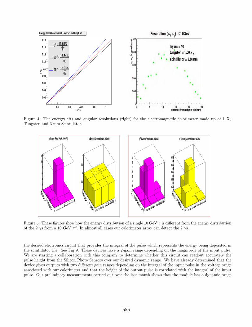
• 40 layers made up of 3.50mm of Tungsten(1 X0), 3.00mm of Scintillator surrounded by 100µ of Radiant mirrorpaper, and 1 mm of empty space. The effective energy and spatial resolutions are shown in Figure 4.
Using a parametric function describing the various resolutions we will study, during the next year, how well wecan separate the W and Z signals using the TPC tracker of the US and European Large detector, of the GLC detectordesigned by our Asian colleagues and using the silicon tracker of the American Silicon based detector. This workis being spearheaded by Jason Gray with three undergraduates under his direction. Steven Wagner will work withour group to help understand how to use the tracking Fast MC smearing routines.He will work with Jason Gray andJoseph Proulx. This work will be a main effort in 2005 but may well continue into 2006.
0.3 Pattern Recognition
We have a program to determine the photons energy and direction when they come from π0 decays. Ourpreliminary results are shown in Figures 5,6,7,8. The student doing this work graduated last summer; hence wehave to continue this work with other students and this has stopped our progress. We have now reinitiated this effortand it will continue through 2006. We will reconstruct these photons in the middle of a Z or W hadronic decay todetermine how well we can reconstruct the π0s and ultimately the W and Z.
This result needs to be viewed in the context that in a 500 GeV Z or W hadronic decay only a few % of the π0shave energies above 50 GeV. Most of them are 20 GeV or less.
233553

E1/0.2 0.4 0.6 0.8 1
/Es
0.02
0.04
0.06
0.08
0.1
0.12
Chi2 / ndf = 19.48 / 10 0.0002446 –Y-Intercept = 0.0005983
0.001043 –Resolution = 0.11 Energy Resolution 2mm, 60 Layers Chi2 / ndf = 19.48 / 10
0.0002446 –Y-Intercept = 0.0005983 0.001043 –Resolution = 0.11
E11.00% - o0
E11.67% - o30
E12.87% - o45
Figure 2: The energy(left) and angular resolutions (right) for the electromagnetic calorimeter made up of 1/2 X0
Tungsten and 2 mm Scintillator.
E1/0.2 0.4 0.6 0.8 1
/Es
0.02
0.04
0.06
0.08
0.1
0.12
0.14
0.16
Chi2 / ndf = 8.904 / 10 0.0003071 –Y-Intercept = 0.0003908
0.001317 –Resolution = 0.1319 Energy Resolution 3mm, 40 layers Chi2 / ndf = 8.904 / 10
0.0003071 –Y-Intercept = 0.0003908 0.001317 –Resolution = 0.1319
E13.19% - o0
E13.88% - o30
E15.32% - o45
Figure 3: The energy(left) and angular resolutions (right) for the electromagnetic calorimeter made up of 3/4 X0
Tungsten and 3 mm Scintillator.
0.4 Electronics
We have received a few Silicon Photo Sensors from Russia and an electronic readout schematic with the help fromFelix Sefkow from DESY. We have developed the electronic readout further in collaboration with Paul Beckingham,the electronics engineer in the Joint Institute for Laboratory Astrophysics (JILA) at the University of Colorado,Boulder.
We have received as a loan a device just produced by Multi Channel Systems (MCS) [2] that replicates very closely
234554
E1/0.2 0.4 0.6 0.8 1
/Es
0.02
0.04
0.06
0.08
0.1
0.12
0.14
0.16
0.18
Chi2 / ndf = 23.31 / 10 0.0003442 –Y-Intercept = 0.0007422
0.001445 –Resolution = 0.1569 Energy Resolution, 3mm 40 Layers, 1 rad length W Chi2 / ndf = 23.31 / 10
0.0003442 –Y-Intercept = 0.0007422 0.001445 –Resolution = 0.1569
E15.69% - o0
E16.64% - o30
E18.23% - o45
Figure 4: The energy(left) and angular resolutions (right) for the electromagnetic calorimeter made up of 1 X0
Tungsten and 3 mm Scintillator.
1 1.21.41.61.8 2 2.22.42.62.8 3
11.21.41.61.82
2.22.42.62.830
2
4
6
8
10
12
Event (First Peak ,10GeV)g
1 1.21.41.61.8 2 2.22.42.62.8 3
11.21.41.61.82
2.22.42.62.83-1
-0.5
0
0.5
1
Event (Second Peak ,10GeV)g
1 1.21.41.61.8 2 2.22.42.62.8 3
11.21.41.61.82
2.22.42.62.830
1
2
3
4
5
6
7
Event (First Peak ,10GeV)0p
1 1.21.41.61.8 2 2.22.42.62.8 3
11.21.41.61.82
2.22.42.62.830
0.050.1
0.150.2
0.250.3
0.350.4
0.45
Event (Second Peak ,10GeV)0p
Figure 5: These figures show how the energy distribution of a single 10 GeV γ is different from the energy distributionof the 2 γs from a 10 GeV π0. In almost all cases our calorimeter array can detect the 2 γs.
the desired electronics circuit that provides the integral of the pulse which represents the energy being deposited inthe scintillator tile. See Fig 9. These devices have a 2-gain range depending on the magnitude of the input pulse.We are starting a collaboration with this company to determine whether this circuit can readout accurately thepulse height from the Silicon Photo Sensors over our desired dynamic range. We have already determined that thedevice gives outputs with two different gain ranges depending on the integral of the input pulse in the voltage rangeassociated with our calorimeter and that the height of the output pulse is correlated with the integral of the inputpulse. Our preliminary measurements carried out over the last month shows that the module has a dynamic range
235555
1 1.21.41.61.8 2 2.22.42.62.8 3
11.21.41.61.822.22.42.62.8302468
1012141618
Event (First Peak ,15GeV)g
1 1.21.41.61.8 2 2.22.42.62.8 3
11.21.41.61.822.22.42.62.83-1
-0.5
0
0.5
1
Event (Second Peak ,15GeV)g
1 1.21.41.61.8 2 2.22.42.62.8 3
11.21.41.61.822.22.42.62.830
2
4
6
8
10
Event (First Peak ,15GeV)0p
1 1.21.41.61.8 2 2.22.42.62.8 3
11.21.41.61.822.22.42.62.830
0.20.40.60.8
11.21.41.6
Event (Second Peak ,15GeV)0p
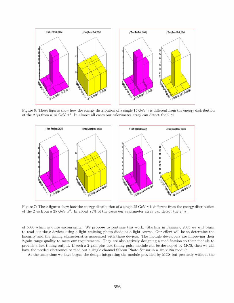
Figure 6: These figures show how the energy distribution of a single 15 GeV γ is different from the energy distributionof the 2 γs from a 15 GeV π0. In almost all cases our calorimeter array can detect the 2 γs.
1 1.21.41.61.8 2 2.22.42.62.8 3
11.21.41.61.82
2.22.42.62.830
5
10
15
20
25
30
Event (First Peak ,25GeV)g
1 1.21.41.61.8 2 2.22.42.62.8 3
11.21.41.61.82
2.22.42.62.83-1
-0.5
0
0.5
1
Event (Second Peak ,25GeV)g
1 1.21.41.61.8 2 2.22.42.62.8 3
11.21.41.61.82
2.22.42.62.8302468
1012141618
Event (First Peak ,25GeV)0p
1 1.21.41.61.8 2 2.22.42.62.8 3
11.21.41.61.82
2.22.42.62.830
0.10.20.30.40.50.60.70.8
Event (Second Peak ,25GeV)0p
Figure 7: These figures show how the energy distribution of a single 25 GeV γ is different from the energy distributionof the 2 γs from a 25 GeV π0. In about 75% of the cases our calorimeter array can detect the 2 γs.
of 5000 which is quite encouraging. We propose to continue this work. Starting in January, 2005 we will beginto read out these devices using a light emitting photo diode as a light source. Our effort will be to determine thelinearity and the timing characteristics associated with these devices. The module developers are improving their2-gain range quality to meet our requirements. They are also actively designing a modification to their module toprovide a fast timing output. If such a 2-gain plus fast timing pulse module can be developed by MCS, then we willhave the needed electronics to read out a single channel Silicon Photo Sensor in a 1in x 2in module.
At the same time we have begun the design integrating the module provided by MCS but presently without the
236556

1 1.21.41.61.8 2 2.22.42.62.8 3
11.21.41.61.822.22.42.62.830
10
20
30
40
50
60
Event (First Peak ,50GeV)g
1 1.21.41.61.8 2 2.22.42.62.8 3
11.21.41.61.822.22.42.62.83-1
-0.5
0
0.5
1
Event (Second Peak ,50GeV)g
1 1.21.41.61.8 2 2.22.42.62.8 3
11.21.41.61.822.22.42.62.830
10
20
30
40
50
60
Event (First Peak ,50GeV)0p
1 1.21.41.61.8 2 2.22.42.62.8 3
11.21.41.61.822.22.42.62.83-1
-0.5
0
0.5
1
Event (Second Peak ,50GeV)0p
Figure 8: These figures show how the energy distribution of a single 50 GeV γ is different from the energy distributionof the 2 γs from a 50 GeV π0. For this particular example we can not observe the 2nd γ. In about 40% of the casesour calorimeter array can detector the 2 γs.
fast timing signal. This is shown in Figure 10.If we are successful during our early 2005 measurements to determine that these modules can be used then we
will be able to specify more exactly the various gains and time constants desired for our exact application. If MCScan provide a prototype that meets our requirements to our satisfaction then we propose to integrate 100 of thesemodules into a prototype assembly. This would accept pulses from 100 Silicon Photo Detectors, create low and highgain range pulse integral outputs as well as a fast timing pulse for every channel. We will then design the additionalhardware to send the data to a computer for analysis. The prototype instrument will also provide the 50v bias forthe Silicon Photo Sensors and the ± 5v adequate for the 100 modules.
We expect, if successfull by the middle of 2005, to be in a position to work with MCS to provide us a large numberof these modules at a competitive price. They are only a relatively small firm and are interested in collaboratingwith us to provide a large number of modules, either by producing them directly or by allowing us to organize theproduction through a licensing agreement. We can then begin to organize the production and testing of a largenumber of modules. We can expect this work to cover the period of 2005. If successful we propose to order 2,300 ofthese in 2006 and 2,300 in 2007 to install into our 50cm x 50cm test calorimeter, 100 tiles per layer and 45 layers, toplace in a test beam.
0.5 Study of Scintillator Elements
We studied the relative light observed from scintillator tiles when covered with Tyvek paper [3] and with RadiantMirror paper [4]. This was done using cosmic rays. The results, as shown in Figure 11, indicate that Radiant Mirrorgives us 20% more signal than Tyvek covering the same scintillator tile. This work is now completed and we willuse Radiant Mirror paper to provide the cover to our scintillator tiles. The work is discussed in http://hep-www.
colorado.edu/SUSY/grp_meas.html; it was carried out by graduate student Martin Nagel in collaboration withundergraduates Jesse Smock and Keith Drake.
237557

Figure 9: Schematic of electronics to readout the Silicon Photo Sensors as designed by Paul Beckingham.
0.6 Study of Light Transmission in Scintillating Fibers
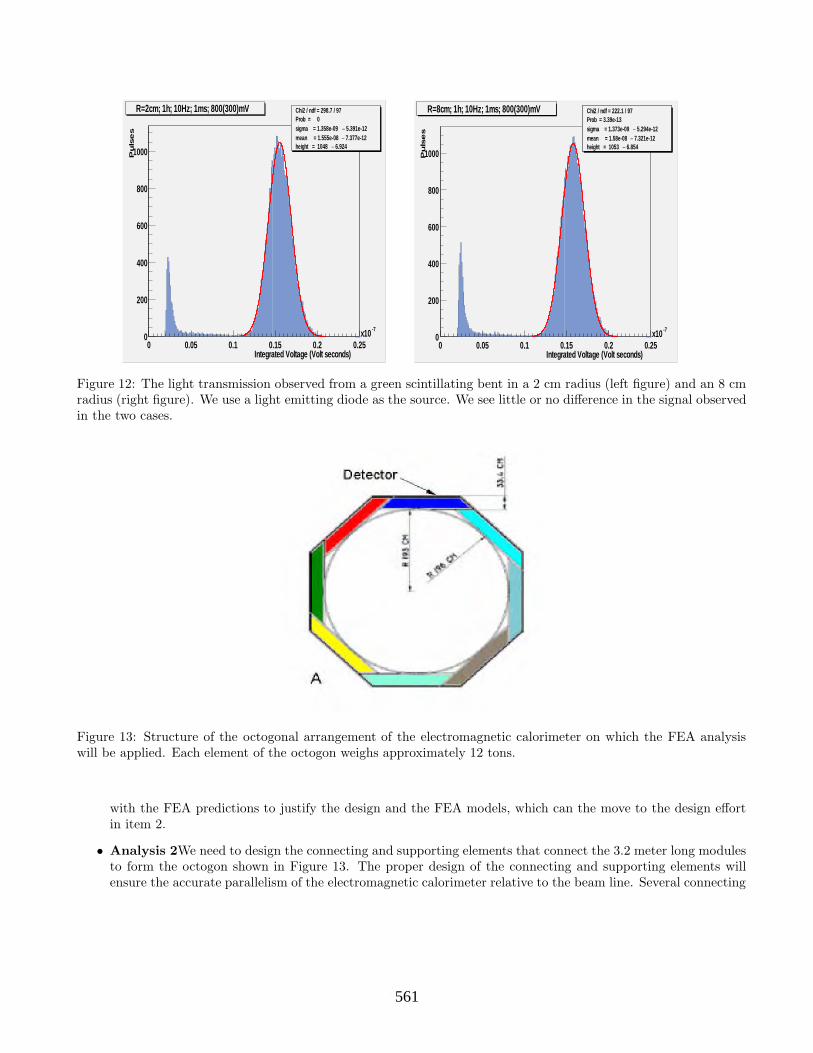
We measured the relative light tranmission in green shifting scintillating fibers when the fiber was bent in acircle of radius 8, 6, 4 ,2 cm. We used a light emitting diode as the ligth source. The results for 2 and 8 cmare shown in Figure 12. The same signal amplitude was seen for the case of 4 and 6 cm. This work is discussedin http://hep-www.colorado.edu/SUSY/grp_meas.html and is completed. This work was carried out by MartinNagel and collaborators.
We have begun a long time scale measurement of the light transmission of these fibers over the period of a yearto determine whether the fiber bent in the 2 cm radius structure deteriorates on this time scale. We do this bycomparing the light transmission of the fibers in the 8 cm radius and the 2 cm radius as a function of time anddetermine whether any differences appear. This work is being carried out by Martin Nagel and collaborators.
0.7 Production of Extruded Scintillator
We have measured the thickness uniformity of extruded scintillator produced by the Fermilab- NIU group. Wehave observed variations of .07 mm in 5 mm thick pieces, mainly near the edges. We have begun a program, incollaboration with the NIU-Fermilab group, to produce 2 or 3 mm thick pieces with variations in thickness no largerthan .03 mm. and variations in width no larger than 1 mm in 15 cm wide pieces. The measurements we have carriedout so far are recorded in http://hep-www.colorado.edu/SUSY/grp_meas.html. To carry out this work we likelywill need to build a new molding unit; this would be built by the NIU-Fermilab group. This effort will be carriedout during the year 2005. Eric Erdos is working on this with Keith Drake.
238558
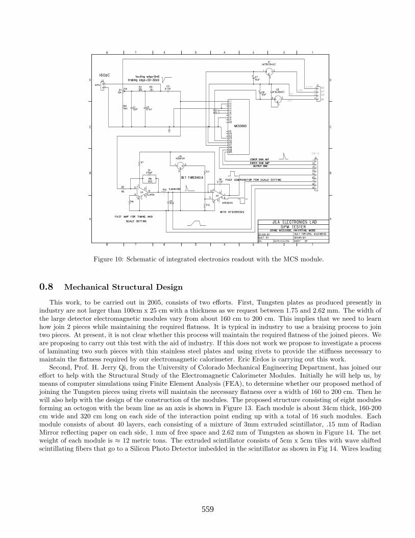
Figure 10: Schematic of integrated electronics readout with the MCS module.
0.8 Mechanical Structural Design
This work, to be carried out in 2005, consists of two efforts. First, Tungsten plates as produced presently inindustry are not larger than 100cm x 25 cm with a thickness as we request between 1.75 and 2.62 mm. The width ofthe large detector electromagnetic modules vary from about 160 cm to 200 cm. This implies that we need to learnhow join 2 pieces while maintaining the required flatness. It is typical in industry to use a braising process to jointwo pieces. At present, it is not clear whether this process will maintain the required flatness of the joined pieces. Weare proposing to carry out this test with the aid of industry. If this does not work we propose to investigate a processof laminating two such pieces with thin stainless steel plates and using rivets to provide the stiffness necessary tomaintain the flatness required by our electromagnetic calorimeter. Eric Erdos is carrying out this work.
Second, Prof. H. Jerry Qi, from the University of Colorado Mechanical Engineering Department, has joined oureffort to help with the Structural Study of the Electromagnetic Calorimeter Modules. Initially he will help us, bymeans of computer simulations using Finite Element Analysis (FEA), to determine whether our proposed method ofjoining the Tungsten pieces using rivets will maintain the necessary flatness over a width of 160 to 200 cm. Then hewill also help with the design of the construction of the modules. The proposed structure consisting of eight modulesforming an octogon with the beam line as an axis is shown in Figure 13. Each module is about 34cm thick, 160-200cm wide and 320 cm long on each side of the interaction point ending up with a total of 16 such modules. Eachmodule consists of about 40 layers, each consisting of a mixture of 3mm extruded scintillator, .15 mm of RadianMirror reflecting paper on each side, 1 mm of free space and 2.62 mm of Tungsten as shown in Figure 14. The netweight of each module is ≈ 12 metric tons. The extruded scintillator consists of 5cm x 5cm tiles with wave shiftedscintillating fibers that go to a Silicon Photo Detector imbedded in the scintillator as shown in Fig 14. Wires leading
239559

Figure 11: The observed signal from 2mm thick scintillator tiles covered with Tyvek and with Radiant Mirror. Thesignal from the tile when covered with Radiant Mirror (red) is 20%larger than when the tile is covered with Tyvek(white).
from the Silicon Photo Detector through the 1 mm free space go to the electronics located on the edge of the detector.Properly designing and integrating these elements into a detector with proper mechanical stiffness to ensure
overall flatness of the detector is critical to the success of the proposed calorimeter. In addition, the proceduresfor assembling the detectors into the final structure and the mechanism to ensure integral accurate parallelism withrespect to the beam line is also crucial to the success of the detector. Neither the scintillator nor the wires from thescintillator to the outside can feel any pressure from the Tungsten plates. Hence, during 2005, we propose to carryout two finite element analysis:
• Analysis 1Design a module detector with proper loading carrying mechanism so that the first few layers of theelectromagnetic calorimeter are protected given the self weight of the module and to ensure that the deflectionscan meet the stiffness requirements. The major challenge in designing the detector comes from the distinctdimensions between the basic elements such as the 5cm x 5cm scintillator tiles, the 1 mm free space, and thelength (3.2 m) of each module. Also we estimate each module to weigh 12 metric tons. Such a heavy weightcould create a significant deflection of the detector and may crush the scintillator in the first few layers. Inorder to study how to overcome these challenges we will carry out a FEA. The iterative design methodologyof concept-design/FEA-analysis/modifying-design will be employed. In addition, in order to ensure that theproposed design can meet the system requirements, a 50cm x 50cm detector with an initial Al backing followedby four layers of /relector/scintillator/reflector/ space/tungsten will be machined and subjected to mechanicaltests. These tests will consist of compression, tension and three point bending. The test results will be compared
240560
Integrated Voltage (Volt seconds)0 0.05 0.1 0.15 0.2 0.25
-7x10
Pu
lse
s
0
200
400
600
800
1000
Chi2 / ndf = 298.7 / 97Prob = 0
5.391e-12 –sigma = 1.358e-09 7.377e-12 –mean = 1.555e-08
6.924 –height = 1048
R=2cm; 1h; 10Hz; 1ms; 800(300)mV Chi2 / ndf = 298.7 / 97Prob = 0
5.391e-12 –sigma = 1.358e-09 7.377e-12 –mean = 1.555e-08
6.924 –height = 1048
Integrated Voltage (Volt seconds)0 0.05 0.1 0.15 0.2 0.25
-7x10
Pu
lse
s
0
200
400
600
800
1000
Chi2 / ndf = 222.1 / 97Prob = 3.39e-13
5.294e-12 –sigma = 1.373e-09 7.321e-12 –mean = 1.58e-08
6.854 –height = 1053
R=8cm; 1h; 10Hz; 1ms; 800(300)mV Chi2 / ndf = 222.1 / 97Prob = 3.39e-13
5.294e-12 –sigma = 1.373e-09 7.321e-12 –mean = 1.58e-08
6.854 –height = 1053
Figure 12: The light transmission observed from a green scintillating bent in a 2 cm radius (left figure) and an 8 cmradius (right figure). We use a light emitting diode as the source. We see little or no difference in the signal observedin the two cases.
Figure 13: Structure of the octogonal arrangement of the electromagnetic calorimeter on which the FEA analysiswill be applied. Each element of the octogon weighs approximately 12 tons.
with the FEA predictions to justify the design and the FEA models, which can the move to the design effortin item 2.
• Analysis 2We need to design the connecting and supporting elements that connect the 3.2 meter long modulesto form the octogon shown in Figure 13. The proper design of the connecting and supporting elements willensure the accurate parallelism of the electromagnetic calorimeter relative to the beam line. Several connecting
241561

Figure 14: Spatial Structure of every layer and scintillator tile arrangement with silicon photo detector in place. TheFEA analysis will take this arrangement into account.
and supporting mechanisms will be designed and analyzed using FEA and the best design will be chosen.
All this computer analysis work we propose to carry out in 2005. We propose that the work in 2006 consists ofbuilding a 40/45 layer calorimeter to place in a test beam to justify the resolution results we have determined withour simulations and our electronics development. Hence we propose to be ordering the pieces to produce a 50cmx 50cm by 40/45 layer electromagnetic calorimeter during the three year period 2005-2007. The thickness of thescintillator and tungsten plates will depend on the results we obtain during the first half of 2005.
0.9 The Budget
The main areas of work in the next three years are four:
• To continue with our simulation work to show the effectiveness of our calorimeter design in separating Wand Z hadronic decays. This work will continue to be carried out by a graduate student and undergraduatessupported mainly by University funds. We are requesting funds for the one graduate student, Jason Gray.
• To carry out the development of the electronics for the electromagnetic calorimeter and to purchase 100 siliconphoto-detectors and 100 modules from MCS to develop a proof of principle. This R&D can be applied to anycalorimeter being designed that uses these silicon photo-detectors. The cost of the electronics engineer timeat $100/hour is $20K. The cost of the 100 Silicon Photo Sensors is estimated to be $4K and the cost of themodules we estimate at $10K. The total is $34K. This cost is for the first year only. The cost for the secondand third year is associated with the construction of the test calorimeter to go into a test beam.
• To develop the extruded scintillator program requires the construction of appropriate tooling and die and thepurchase of 60 bars 150 mm wide by 1000 mm long by 2 mm thick. The estimated cost as provided by Fermilabwith labor and indirect charges (16.1% M&S, 30.35% Labor) is $49.83K. This total cost is distributed between2 years with the tooling, die, some materials and some labor in the first year.
• The cost estimate to carry out the FEA to construct the tungsten panels and simulate a module is as follows:0.5 month of Prof. Qi’s salary which amounts to $4,208, the salary of a student doing a master’s thesis on this
242562

work which amounts to $23K, and the cost of the Tungsten material, etc. which costs $6K. The cost of theTungsten for the test beam module is estimated at $85K
The total cost for 2005 is $154,528 and the added overhead of 48.7% is $37,237.
3 Year Budget Table
Duration: 1-1-2005 to 12-31-2007
Principal Investigator: Uriel Nauenberg
ITEM 2005 2006 2007
A. SALARIES AND WAGES(on Campus)Faculty:Prof. Jerry Qi
100% time 0.5 mos. summer 4,208
Staff:Graduate Student:Jason Gray
50% 9 mos. AY 16,516 17,135
100% 2 mos. Summer 7,491 7,772
Mech. Eng. Student(To be named)
50% 9 mos. AY 15,006
100% 2 mos. Summer 6,806
To be named
50% 9 mos. AY 17,778
100% 2 mos. Summer 8,063
Total Salaries and Wages 50,026 24,907 25,841
B. FRINGE BENEFITSFaculty:21.2% 892
GRAs:3.2% 1,466 797 827
Total Fringe Benefits 2,358 797 827
243563

ITEM 2005 2006 2007
C. PERMANENT EQUIPMENT100 Silicon Photo Sensors 4,000
4,600 Silicon Photo Sensors 46,000
100 MCS Electronic Modules 10,000
2,300 MCS Electronic Modules 69,000
2,300 MCS Electronic Modules 69,000
Tungsten Plates for Testing 6,000
Lamination Material+Labor 2,000
50 50cm x 50 cm Tungsten Plates 85,000
Extruded Scintillator Tooling 10,000
Extruded Scint. Die Develop. 2,000
Extruded Scintillator Panels Prod. 18,915
Extruded Scintillator Panels Prod. 18,915
500 Scintillator Fibers 5,000
2,300 Analog to Digital Con. 23,000
2,300 Analog to Digital Con. 23,000
Total Permanent Equipment 52,915 246,915 92,000
D. Other Direct CostsElectronics Support 20,000 10,000 5,000
Materials and Supplies 1,000 5,000 5,000
Tuition Remission:1 GRA (res) 2,794 3,144 3,537
Tuition Remission:1 GRA (non-res.) 22,434
Total Other Direct Costs 46,229 18,144 13,537
E. TravelTravel to Meetings to Present Results 3,000 3,000 3,000
Travel to Test Beams 6,000
Total Travel 3,000 3,000 9,000
F. TOTAL DIRECT COSTS 154,528 293,762 141,204
G. INDIRECT COSTS(48.7%) 37,237 21,415 22,377
H. TOTAL COST 191,766 315,177 163,581
244564
Bibliography
[1] Tsukamoto et. al. Precision Studies of Supersymmetry at Future Linear e+e− CollidersPhys. Rev. D 51, 3153 (1995).
[2] Multi Channel System Corp., distributor Wiener US, 300 East Auburn Ave., Springfield, Ohio, 45505.
[3] Tyvek, DuPont Corp., Richmond, Virginia.
[4] 3M Corporation, Kay Bidwell, [email protected]
245565

6.4
6.4
Calorimetry
6.4: Particle Flow Studies with the Silicon Detector (SiD) at the International Linear
Collider (ILC)
(renewal)
Calorimetry
Contact person Usha Mallik
[email protected] (319) 335-0499
Institution(s)
Iowa
Funds awarded (DOE) FY04 award: 50,000
New funds requested FY05 request: 83,910 FY06 request: 98,849
FY07 request: 0
246566

Particle Flow Studies
with the Silicon Detector (SiD) at the
International Linear Collider
Calorimetry
The University of Iowa
Matthew J. Charles, Wolfgang F. Mader, Usha Mallik, and Niels T. Meyer
Contact Person: Usha MallikE-mail: [email protected]: (319) 335-0499
Year 1: $83,910Year 2: $98,849
January 2005
247567
Particle Flow Studies
with the Silicon Detector (SiD) at the
International Linear Collider
Matthew J. Charles, Wolfgang F. Mader, Usha Mallik, and Niels T. Meyer
(The University of Iowa)
January 2005
1 Introduction
In 2004, The University of Iowa group has concentrated their Linear Collider R&Dactivities on the simulation of the electromagnetic calorimeter (EMCal) for the Sil-icon Detector (SiD) at the International Linear Collider (ILC).
An excellent jet energy resolution is essential in order to achieve maximum sen-sitivity to the physics anticipated from the ILC. It is an important benchmark forthe detector design in general and for the design of the calorimeter in particular,e.g. optimization of the granularity. A finely segmented detector should be matchedby powerful reconstruction software for which a Particle Flow Algorithm (PFA1) isa promising approach.
The group, led by Usha Mallik, has been an integral part of simulation efforts atSLAC, working mainly on reconstruction software necessary for the proof of principleof a PFA. The milestones achieved in the year 2004 are discussed, focusing on thecontributions from the Iowa group. The future plans for simulation efforts are laidout.
1also referred to as ‘Energy Flow Algorithm’
248568

2 The Importance of the EMCal in a PFA
Calorimetry plays an essential role in a PFA in the SiD design. The current goalof the Iowa group is the development of an algorithm to detect and trace minimumionizing particles (MIPs) in the EMCal, and to reconstruct associated showers with-out assistance from the central tracking system. There are several benefits from thisapproach, three of which are discussed below.
1. Electromagnetic and hadronic showers can be separated by analyzing theirshower shapes. However, having a longitudinally segmented calorimeter, theactual starting point of the shower and the presence or lack of a MIP-trackassociated with it can be used as an additional distinctive feature to increasethe separation power.
2. For charged particles in the forward angular region, the number of hits in thecentral tracking system is limited by the detector geometry. The extrapola-tion of identified MIP-tracks to the last tracking layers can be used to assignunassociated tracker hits and thus improve the tracking efficiency.
3. Charged tracks produced in decays of long-lived particles like K0S, Λ, or possible
SUSY particles only leave a limited number of hits in the central trackingsystem. The identification of MIP-tracks can help to improve the detectionefficiency in the same way as described above.
Efficient and precise reconstruction of MIP-tracks in the EMCal are important stepstowards identification of showers from neutral hadrons and reconstruction of long-lived particles.
3 Personnel Involved
The SiD effort at the ILC is lead by Marty Breidenbach (SLAC). The University ofIowa group has been working closely with his group in the simulation effort for thisdetector design since 2003 and has made essential contributions towards the proofof principle of a PFA.
At present, Wolfgang Mader, a postdoc from The University of Iowa, is work-ing full-time on this project together with the simulation software group at SLAC:Norman Graf, Ron Cassel and Tony Johnson.
Niels Meyer, a new postdoc who has just joined the Iowa group having com-pleted his Ph.D. at the University of Hamburg, will work full-time on the ILC effort.Matthew Charles, a postdoc previously working on this project, is also rejoining theeffort.
249569
4 Simulation Overview
4.1 SiD Configuration
The simulation efforts are based on the SiD design which is described in detailelsewhere [1]. The EMCal, which is the main focus of the present effort of theIowa group, consists (in the barrel region) of 30 layers of (0.5 × 0.5) cm2 siliconcells alternating with 0.25 cm thick tungsten layers. It extends from a radius ofrmin ≈ 127 cm to rmax ≈ 142 cm, representing a total of 20 radiation lengths (X0)or 0.8 hadron interaction lengths (λI). In combination with an effective PFA, thehigh granularity will help provide an excellent jet energy resolution.
4.2 Technical Details
In 2004, the detector simulation used at SLAC has been migrated from a GISMO [2]based simulation to a simulation based on GEANT4 [3]. The configuration of thedetector is described using the XML language. The GEANT4 package is widelyused in high energy physics and provides realistic description of the response of theindividual detector components. The simulation packages previously developed bythe Iowa group had to be migrated to work with the updated detector simulation.
The reconstruction and analysis software is written in JAVA, using the hep.lcd
framework [4]. Simulated events used are stored in the SIO format [5]. The analysisis presently carried out using JAVA Analysis Studio version 3 [6] (migrating fromversion 2) and ROOT [7].
4.3 Event Samples
The SLAC group provided event samples to develop the necessary reconstructiontools and to test the overall performance of the SiD design. The University ofIowa group was involved in the testing of event samples and the debugging of thedigitization process.
The event samples used in the simulation effort comprise two categories:
• Single particle samples:The detector response is simulated for (a) charged pions in a momentum rangeof 1GeV < pπ < 10GeV and an angular range of 4 < Θ < 176, and (b)events containing decays K0
S → π+π− of momentum 10GeV. These samplesare used to develop and test the algorithms described later in the document.
• Z0 and tt events:These physics events were used in order to test the algorithms under realistic
250570

conditions, an important step towards developing an effective PFA. These testswill be extended to other event topologies.
4.4 Future Developments
The SLAC group is working towards implementing a simulation package which willproduce output in LCIO format [8]. LCIO is a general format agreed on by theILC community in the US, Europe and Asia. It allows a direct comparison of thedifferent detector designs and the various simulation efforts. A common formatmakes it possible to share reconstruction and analysis algorithms. These tools forthe new framework are currently developed by the SLAC software group (their effortwill be joined by The University of Iowa group).
5 Simulation Effort at The University of Iowa
In this section, the simulation effort of The University of Iowa group is explainedin detail. The group has focused on the development of reconstruction software forthe EMCal, an important ingredient of a PFA.
In the first step, the identification of MIP-tracks in the EMCal within the busyenvironment of multi-hadron final states was developed. This part has been finishedin 2004 and was presented to the ILC community on several occasions [9, 10].
The next steps for the PFA are measurement and identification of electromag-netic and hadronic showers. The separation of contributions from charged and neu-tral hadrons is an important step. This is under development and the current statusis presented.
5.1 Identification and Reconstruction of MIP-Tracks
MIP-tracks leave a very characteristic signature of isolated energy deposits (oc-casionally accompanied by a close-by second energy deposit due to δ-rays) in theEMCal. Starting from a seed point which is obtained from the track informationin the central tracking system, they can be tracked with high efficiency as shown inprevious studies by Matthew Charles in 2003.
In 2004, this algorithm has been verified using GEANT4 simulated events. Cri-teria for identifying MIP seeds independent of the central tracking system have beendeveloped and tested. The algorithm has been further extended using pion samplesand events containing Z0-decays and tt physics processes.
The efficiency of the algorithm exceeds 99% for pions that only leave a MIP-track in the EMCal. In the current detector design, however, about half of thecharged hadrons start showering within the EMCal. For particles with transverse
251571

EndPoint Resolution (MC−Nucleus) Entries : 2251 OutOfRange : 4 Mean : 0.44313 Rms : 3.5990
gauss amplitude : 419.34 mean : −0.078759 sigma : 0.60037
gauss_1 amplitude : 49.341 mean : 1.5205 sigma : −3.6829
sum amplitude : 419.34±18.53 mean : −0.078759±0.028881 sigma : 0.60037±0.03192 amplitude_1 : 49.341±2.839 mean_1 : 1.5205±0.1914 sigma_1 : −3.6829±0.2191 χ² : 2.4301
500
0
100
200
300
400
Double Gaussian Fit
MC Simulation
Ent
ries
/ 0.
5cm
(True Radius − Reconstructed Radius) / cm4 8 12−12 −8 −4 0
Figure 1: Resolution of the radial position of the showering point using single pion samples.Superimposed is a fit with a double Gaussian, where the two individual contri-butions are shown separately. The resolution of the radial position as obtainedfrom the core Gaussian is ±0.6 cm corresponding to a reconstruction uncertaintyof ± 1 layer in the EMCal. Physics processes contributing to the tails on theleft and the right side of the distribution have been identified as π → µνµ decaysand scattering processes, respectively.
momentum in excess of 1GeV (i.e. sufficient to reach the barrel EMCal) an overallreconstruction efficiency of about 90% was achieved.
The analysis has been further extended to the reconstruction of the showeringpoint. A precision of ±0.6 cm in the radial position has been achieved as illustratedin Figure 1, corresponding to ±1 layer in the EMCal. The tails of the distributionextending to the left and the right side of the peak have been studied and identifiedas events containing π → µνµ decays and scattering processes, respectively.
5.2 MIP-Track Fitting
5.2.1 Reconstruction of MIP-Segments
The seed for a MIP-candidate is initially defined as three isolated hits in four consec-utive EMCal layers. In very busy events e.g. from tt production, this approach leadsto too many reconstructed MIP-track segments. This is partly due to the overlap ofMIP-tracks with hadronic or electromagnetic showers from other particles.
Therefore, a two-pass algorithm has been developed. The algorithm is appliedonce, starting from the inner part of the detector, following the MIP-track as far as
252572
isolated hits are found in successive outer layers. In a second pass, the algorithmstarts from the outer part of the detector, following the MIP-track as long as isolatedhits are found in successive inner layers of the EMCal2. These MIP-segments arethen matched using χ2 criteria described below.
5.2.2 Association of MIP-Segments
A five parameter helix fit is performed to the EMCal hits of each MIP-segmentfound. For every pair of MIP-segments, a two-step χ2 criterion is calculated usingthe fit parameters and the corresponding error matrices.
In the first step, only the track parameters (κ, φ0, d0, tan λ) are used and theefficiency (upper curve) for matching MIP-segments and the background rate fromrandom combinations (lower curve) is displayed in Figure 2(a). By retaining allcombinations with χ2 < 40, an efficiency of ≈ 100% is achieved with a backgroundfraction below 5%. The z component is not included in the first step, since its contri-bution exhibits artifacts due to the projective geometry of the EMCal configurationused in the simulation (for example, when a MIP passing through the EMCal in onetower of cells is scattered into a neighboring tower).
Instead, in a second step, a cut of χ2z
< 80 is used, where χ2z
is calculated fromthe z component of the helix parameters only, on those MIP-combinations that pass
2In order to account for detection inefficiencies, gaps of one layer are allowed.
Fraction
Chi^2_z0
0 10 20 30 40 50 60 70 80 90 1000.20
0.25
0.30
0.35
0.40
0.45
0.50
0.55
0.60
0.65
0.70
0.75
0.80
0.85
0.90
0.95
1.00
Integrated Background
Integrated Signal
Integrated Signal Entries : 25 Mean : 51.537 Rms : 28.357 OutOfRange : 1 SumOfWeights : 23.772
Integrated Background Entries : 25 Mean : 52.433 Rms : 28.196 OutOfRange : 1 SumOfWeights : 8.1238
Fraction
Chi^2
0 20 40 60 80 1000.01
0.1
1
Integrated Background
Integrated Signal
0.20
0.40
0.60
0.80
1.00
χ2 χ2
0.1
1
0.01
Fraction
0 20 40 60 80 100
Fraction
0 20 40 60 80 100
Integrated Signal FractionIntegrated Background Fraction
Integrated Signal FractionIntegrated Background Fraction
(a) (b)
Figure 2: Integrated χ2 distributions as calculated using the helix parameters(κ, φ0, d0, tan λ) (a) and z (b). The upper curves indicate the efficiency forassociating matching MIP-segments, while the lower curves indicate the back-ground rate from random MIP segment combinations. The background fractionin (b) is relative to that remaining after requiring χ2(κ, φ0, d0, tan λ) < 40.
253573
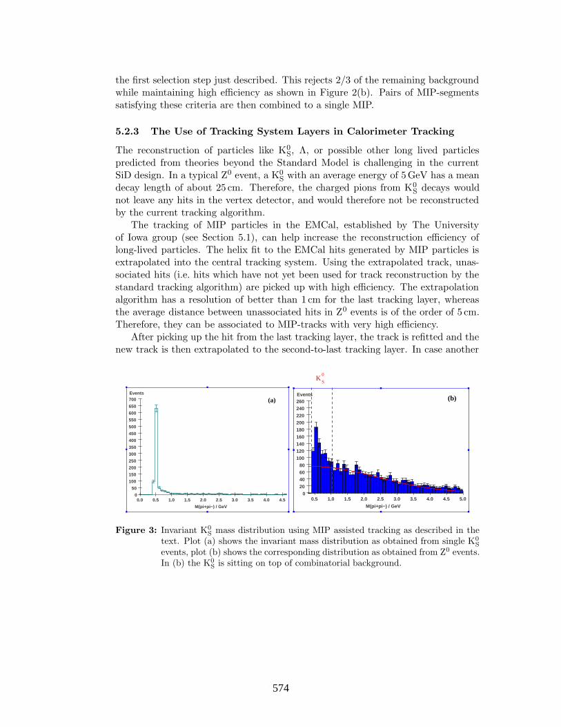
the first selection step just described. This rejects 2/3 of the remaining backgroundwhile maintaining high efficiency as shown in Figure 2(b). Pairs of MIP-segmentssatisfying these criteria are then combined to a single MIP.
5.2.3 The Use of Tracking System Layers in Calorimeter Tracking
The reconstruction of particles like K0S, Λ, or possible other long lived particles
predicted from theories beyond the Standard Model is challenging in the currentSiD design. In a typical Z0 event, a K0
Swith an average energy of 5GeV has a mean
decay length of about 25 cm. Therefore, the charged pions from K0S
decays wouldnot leave any hits in the vertex detector, and would therefore not be reconstructedby the current tracking algorithm.
The tracking of MIP particles in the EMCal, established by The Universityof Iowa group (see Section 5.1), can help increase the reconstruction efficiency oflong-lived particles. The helix fit to the EMCal hits generated by MIP particles isextrapolated into the central tracking system. Using the extrapolated track, unas-sociated hits (i.e. hits which have not yet been used for track reconstruction by thestandard tracking algorithm) are picked up with high efficiency. The extrapolationalgorithm has a resolution of better than 1 cm for the last tracking layer, whereasthe average distance between unassociated hits in Z0 events is of the order of 5 cm.Therefore, they can be associated to MIP-tracks with very high efficiency.
After picking up the hit from the last tracking layer, the track is refitted and thenew track is then extrapolated to the second-to-last tracking layer. In case another
M(pi+pi−) / GeV
Events
0.0 0.5 1.0 1.5 2.0 2.5 3.0 3.5 4.0 4.50
50
100
150
200
250
300
350
400
450
500
550
600
650
700 (a)
M(pi+pi−) / GeV
Events
0.5 1.0 1.5 2.0 2.5 3.0 3.5 4.0 4.5 5.00
20406080
100120140160180200220240260
Z0−Pole EventsK
0
S
(b)
Figure 3: Invariant K0S mass distribution using MIP assisted tracking as described in the
text. Plot (a) shows the invariant mass distribution as obtained from single K0S
events, plot (b) shows the corresponding distribution as obtained from Z0 events.In (b) the K0
S is sitting on top of combinatorial background.
254574
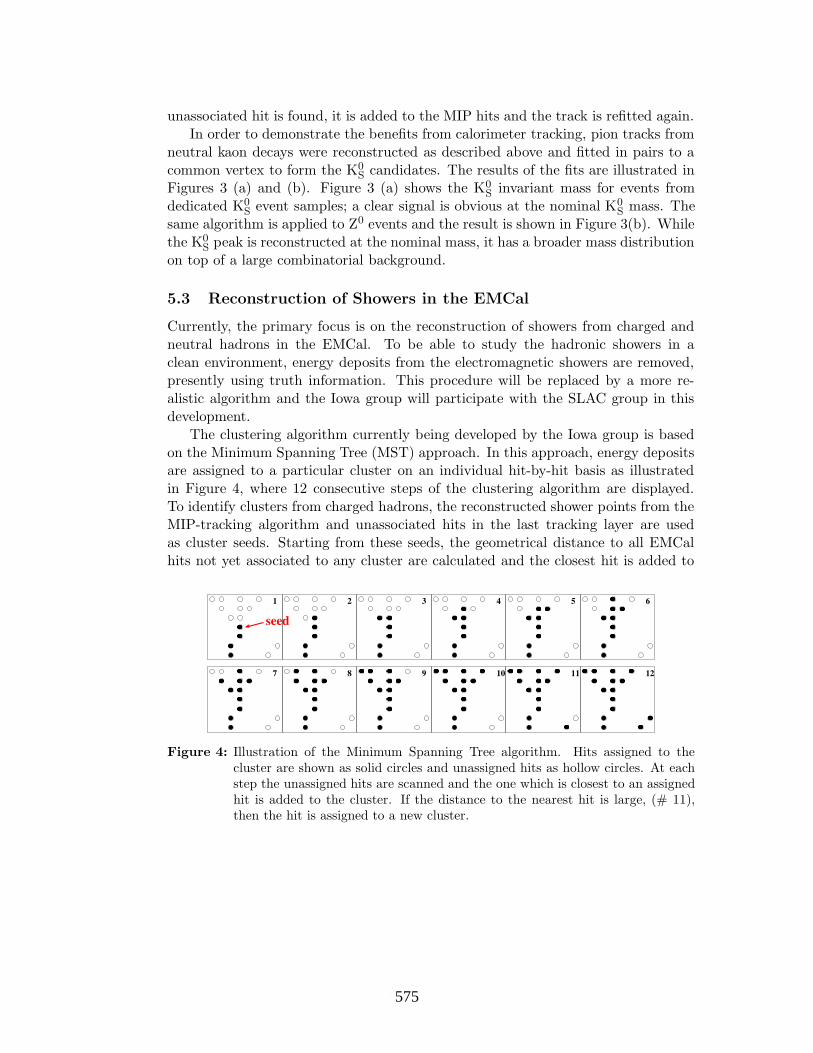
unassociated hit is found, it is added to the MIP hits and the track is refitted again.In order to demonstrate the benefits from calorimeter tracking, pion tracks from
neutral kaon decays were reconstructed as described above and fitted in pairs to acommon vertex to form the K0
S candidates. The results of the fits are illustrated inFigures 3 (a) and (b). Figure 3 (a) shows the K0
Sinvariant mass for events from
dedicated K0S
event samples; a clear signal is obvious at the nominal K0S
mass. Thesame algorithm is applied to Z0 events and the result is shown in Figure 3(b). Whilethe K0
Speak is reconstructed at the nominal mass, it has a broader mass distribution
on top of a large combinatorial background.
5.3 Reconstruction of Showers in the EMCal
Currently, the primary focus is on the reconstruction of showers from charged andneutral hadrons in the EMCal. To be able to study the hadronic showers in aclean environment, energy deposits from the electromagnetic showers are removed,presently using truth information. This procedure will be replaced by a more re-alistic algorithm and the Iowa group will participate with the SLAC group in thisdevelopment.
The clustering algorithm currently being developed by the Iowa group is basedon the Minimum Spanning Tree (MST) approach. In this approach, energy depositsare assigned to a particular cluster on an individual hit-by-hit basis as illustratedin Figure 4, where 12 consecutive steps of the clustering algorithm are displayed.To identify clusters from charged hadrons, the reconstructed shower points from theMIP-tracking algorithm and unassociated hits in the last tracking layer are usedas cluster seeds. Starting from these seeds, the geometrical distance to all EMCalhits not yet associated to any cluster are calculated and the closest hit is added to
Figure 4: Illustration of the Minimum Spanning Tree algorithm. Hits assigned to thecluster are shown as solid circles and unassigned hits as hollow circles. At eachstep the unassigned hits are scanned and the one which is closest to an assignedhit is added to the cluster. If the distance to the nearest hit is large, (# 11),then the hit is assigned to a new cluster.
255575

(a)
Distance to Closest Hit
EMCal Hit Number
20 40 60 80 100 120 140 16005
101520253035404550 (b)
Figure 5: Plot(a) shows the signature of a typical K0S → π+π− decay from a single K0
S
event. Plot (b) displays the distance to the closest hit not yet assigned to thecluster as explained in the text.
the cluster. This procedure is repeated until all EMCal hits have been assigned toclusters. Currently, the hit assignment is based on the geometric distance betweenhits. In future, various weighting algorithms will be studied.
An example of the performance of the algorithm for a typical K0S
event is shown inFigures 5 (a) and (b). The section of the detector where the pions from a K0
S→ π+π−
decay interact with the EMCal is shown in Figure 5(a). Figure 5(b) shows thedistance to the closest hit not yet assigned to the cluster. The spike around hitnumber 70, corresponding to a large geometrical distance, is used as a separationcriterion between the two pions showers.
The current implementation of this algorithm uses the hit coordinates directlyand is therefore largely independent of the detector geometry (e.g. the number ofEMCal layers and cell sizes). Hence, with minimal changes it can also be used withother calorimeter configurations.
These studies have very recently been shown to the SiD simulation commu-nity [10]. The Iowa group was encouraged to pursue these studies and take a leadingrole in the MST-based clustering approach; we therefore expect to continue thesestudies.
6 Future Plans
Substantial progress has been made during the year 2004 towards the proof of prin-cipal of a PFA with important contributions from The University of Iowa group.However, essential ingredients of such an algorithm are still under development ormissing. The Iowa group is playing a central role and is working in close collabora-tion with other simulation groups that are covering different aspects of a PFA.
256576

Our group is an integral part of the simulation effort at SLAC, working closelywith the group of Marty Breidenbach, who is leading the SiD effort. The simulationtools developed by the Iowa group are aimed at the SiD design. We plan to intensifyour efforts in this area. The achievements of our group are summarized in thissection and the prospects for a future involvement, in both the development of aPFA and its evaluation studying benchmark physics cases, are laid out.
6.1 Software Development and SiD Design Studies
The Iowa group has made considerable progress in the development of reconstructionsoftware for the EMCal. A very efficient MIP-tracking algorithm has been developed.A track fitting algorithm using only calorimeter hits has been developed; its benefitsfor particle tracking in general have been demonstrated by reconstructing long-livedparticles with the use of the last layers of the central tracking system. We intendto carry out studies with other EMCal geometries and investigate their influence onthe algorithms developed.
Reconstruction of hadronic showers in the EMCal has started and the first resultsare encouraging. We now intend to intensify these studies with the participation ofMatthew Charles and Niels Meyer.
6.2 Study of Physics Processes
A study of the sensitivity of particular detector designs and reconstruction algo-rithms to physics observables as well as their impact on the accuracy of specificphysics analyses is essential. We propose to participate in this effort, concentratingin particular on processes where the reconstruction software developed by the Iowagroup can be applied, i.e. on processes leaving distinct signatures in the EMCal.
The Iowa group proposes to investigate the following benchmark processes wherean excellent understanding of the calorimetry section is essential and which are ofmajor physical interest at the ILC.
1. Higgs decays to photons, H → γγ
The distinct signature of two isolated photons allows studies of the energyresolution of single high energetic particles from reconstruction of EMCal hitsonly. This decay is of special interest to exploit the Higgs-photon coupling,which is highly sensitive to heavy charged particles beyond the SM particlespectrum.
2. Higgs production in WW-fusion with decays H → bb
The signature of two final state jets allows resolution studies of jet energy andjet-pair mass measurements. WW-fusion is the dominant Higgs production
257577

mechanism at high energies and probes the Higgs-W coupling. The latter isof special interest when deducing the total decay width in case of light Higgsbosons.
3. Double Higgs production ZHH
Events from this process may contain up to six jets, allowing to study the im-pact of calorimeter measurements on combination efficiencies. This process isessential to study the Higgs self coupling and to establish the Higgs mechanismas the origin of electroweak symmetry breaking.
6.3 Plans towards a Particle Flow Algorithm
The long-term goal of the Iowa group is to play a key role in the integration of thevarious components of a PFA, which takes full advantage of the natural interplaybetween all sub-detectors. Such an algorithm is best suited for optimization studiesof the SiD design, e.g. detector geometry or calorimeter segmentation.
The University of Iowa group has been an integral part of the studies so farby providing an efficient MIP-tracking algorithm and working on general EMCalreconstruction. These efforts will be intensified by Niels Meyer joining the group.
7 Resources and Budget
Wolfgang Mader has worked almost full time on simulations and algorithms for de-veloping Particle Flow for SiD since he joined the group in March 2004. Niels Meyer,who graduated from University of Hamburg under the supervision of Professor Rolf-Dieter Heuer (at present Research Director of DESY, Germany), has just joined thegroup to start working full time on this project. Matthew Charles has completedan analysis on BABAR, and expects to rejoin the Particle Flow effort shortly. Two(equivalent) full time postdocs will be involved in the SiD Particle Flow project fromThe University of Iowa. A new graduate student will likely join the effort from latesummer, after moving to the bay area.
The budget is listed below, primarily based on the support for one postdoc. Thepostdoc’s salary is taken at $46,000 with fringe benefits at 18% at The University ofIowa. The second postdoc’s support is obtained by reallocating resources from thebase grant support of the group for BABAR. Travel to the various ILC workshopsfor the two postdocs and for Usha Mallik is included for the year at $12,000. Theindirect costs at Iowa are charged at a rate of 26.6% for off-campus activities (thepostdocs all stay at SLAC where interaction is easier). A total of $83,910 is thusrequested to cover the FY05 cost.
258578

The second year’s budget is anticipated to be similar, with a $2,000 increase insalary for the postdoc and partial support of $8,000 for a graduate student. Tables 1and 2 list the breakdown of the budgets.
Table 1: Budget for the First Year R&D. The total costs quoted include 26.6% for off-campus activities.
Item Direct Cost ($) Total Cost ($)
Salary and Fringe Benefits of Research Associate 46,000 × 1.18 68,718Travel to ILC Meetings (2 RAs and PI) 12,000 15,192Total First Year R&D 83,910
Table 2: Budget for the Second Year R&D. The total costs quoted include 26.6% for off-campus activities.
Item Direct Cost ($) Total Cost ($)
Salary and Fringe Benefits of Research Associate 48,000 × 1.18 71,706Partial Support for a Graduate Student 8,000 × 1.18 11,951Travel to ILC Meetings (2 RAs and PI) 12,000 15,192Total Second Year R&D 98,849
References
[1] SiD Homepage:http://www-sid.slac.stanford.edu/
[2] W. B. Atwood, T. Burnett, R. Cailliau, D. R. Myers and K. M. Storr, “Gismo:An Object Oriented Program For High-Energy Physics Event Simulation AndReconstruction,” Int. J. Mod. Phys. C 3, 459 (1992), R. Cassell, “Full LCDdetector simulation with GISMO,” SLAC-REPRINT-2000-109 Prepared for 5thInternational Linear Collider Workshop (LCWS 2000), Fermilab, Batavia, Illi-nois, 24-28 Oct 2000.
[3] S. Agostinelli et al. [GEANT4 Collaboration], Nucl. Instrum. Meth. A 506, 250(2003).
259579

[4] hep.lcd Homepage:http://www-sldnt.slac.stanford.edu/jas/Documentation/lcd/
[5] http://www-sldnt.slac.stanford.edu/nld/new/Docs/FileFormats/sio.pdf
[6] JAS webpage:http://jas.freehep.org/jas3
[7] ROOT webpage:http://root.cern.ch
[8] LCIO Homepage:http://lcio.desy.de
[9] Linear Collider Simulation Workshop III, Jun-2004:http://www.slac.stanford.edu/∼mader/Talks/LCSIII/LCSIII.pdf
Victoria Linear Collider Workshop, Jul-2004:http://www.linearcollider.ca:8080/lc/vic04/abstracts/detector/calorimetry/wolfgang mader.pdf
ALCPG Calorimetry WG meetings:http://nicadd.niu.edu/cdsagenda//fullAgenda.php?ida=a0450
[10] Argonne SiD PFA workshop, Jan-2005:http://nicadd.niu.edu/cdsagenda//fullAgenda.php?ida=a057
260580

6.5
6.5
Calorimetry
6.5: Development of a silicon-tungsten test module for an electromagnetic calorimeter
(renewal)
Calorimetry
Contact person Raymond Frey
[email protected] (541) 346-5873
Institution(s)
Oregon SLAC
Funds awarded (DOE)
FY04 award: 55,000
New funds requested FY05 request: 45,000
FY06 request: 0 FY07 request: 0
261581
Ray Frey Page 1 University of Oregon
Project name
Development of a silicon-tungsten test module for an electromagnetic calorimeter
Classification
Detector:calorimetry
Institutions and personnel
University of Oregon, Department of Physics and Oregon Center for HEP: Raymond Frey (faculty), David Strom (faculty), physics undergraduates
Stanford Linear Accelerator Center: M. Breidenbach (faculty), D. Freytag, N. Graf, G. Haller
Contact person
Raymond Frey [email protected](541) 346-5873
I. Project Overview
The current LD and SiD detector designs call for a silicon-tungsten (Si-W) electromagnetic calorimeter (ECal) as the best option for providing the necessary density and segmentation to implement the particle flow method (PF, formerly called energy
flow) for reconstruction of jets (and taus) at the LC, capable of achieving jet energy resolution of 0.3/ Ejet, as recommended by LC physics studies. One of the outstanding technical questions is how to integrate a silicon detector wafer with its readout electronics. Since the number of detector pixels for these ECal designs is on order 50 million, a solution to the integration issue, along with the cost of the silicon detectors themselves, is likely to determine the overall viability of the Si-W approach. A few years ago, we proposed1,2 a possible solution to the integration problem and have received LCRD support for two years to pursue this. Our work gives us confidence that we are on the right path and we propose for the next year to complete the initial phase of the R&D – to demonstrate the detector concept with prototypes in an electron test beam – and to move on to the next phase: The development of a full-depth ECal module which incorporates the features required for a realistic LC detector. This module would be part of an international test beam study. The full-depth module requires more funding than is realistically available with the present LCRD program. Hence, its funding is being pursued separately. Here, we focus on completing the development and initial testing of the detector components, the goal being to test a few layers of our prototype detectors and electronics in the lab at Oregon and in an electron beam, hopefully at SLAC.
While we focus on an implementation of our Si-W approach for the SiD design, the basic ideas and R&D are certainly applicable to other Si-W ECal designs, notably LD.
262582

Ray Frey Page 2 University of Oregon
Figure 1. Left: Cartoon of 15 cm Si detector segmented into 5mm pixels. The central rectangle indicates the position and approximate size of the bump-bond array. Right: Schematic of bump bond pad array and bundles of signal traces entering the array from the pixels.
The thrust of our project is to integrate detector pixels on a large, commercially feasiblesilicon wafer, with the complete readout electronics, including digitization, contained in a single chip which is bump bonded to the wafer. This is shown in Fig.1. The starting point for our design uses a pixel size 5 mm across, based on initial PF requirements for photon-hadron separation. This gives N~103 pixels per 6-inch wafer. We take advantage of the low beam-crossing duty cycle (~10-3) to reduce the heat load using power cycling. This scheme has several important properties:
1. The channel count is effectively reduced by a factor N.
2. The cost, to first order, will be independent of the ECal transverse segmentation.
3. Readout gaps can be small (~1 mm), thus maintaining the small Moliere radius intrinsic to tungsten.
The first property, we feel, is necessary for any realistic highly-segmented ECal. In this case, the electronics is likely to be relatively small fraction of the ECal cost. The secondpoint makes the design flexible, so that one can optimize to meet the physics goals. The third is an optimization of the physics capability of the ECal at a given (barrel) radius. For example, the angle subtended by the Moliere radius for an ECal at radius 1.25m with our design is smaller than one with 3mm readout gaps at 1.7m. Hence, this has a significant impact on both performance and overall detector cost.
We note that for a Si-W ECal, the features above remain unique to this R&D.
Collaborations. First, within this R&D, the collaboration consists of the Oregon and SLAC personnel listed above, in addition to V. Radeka of BNL who has collaboratedwith us extensively on the electronics design. Our R&D collaboration has been holdingweekly meetings by telephone for over two years. Between Oregon and SLAC the activities roughly break down as follows:
263583

Ray Frey Page 3 University of Oregon
1. Silicon detector design, procurement, characterization, and testing (Oregon)
2. Readout chip design, procurement, and testing (SLAC)
Recently, we have begun discussions with the HEP group at UC Davis in connection with their bump-bonding facility. This appears to be a good possibility, and members of the UC Davis group will presumably join our R&D effort. In addition to the hardware work, Oregon plans to continue related simulation and software activities. These include, but are not limited to, EGS4 and Geant4 studies, comparisons between the two, and development of PF algorithms. Ultimately, we will use robust PF results to optimize the calorimeter. The LC community is still a long way from this point, although the recent focus on a few detector designs is helpful.
Within the ALCPG, Oregon has strong ties to the Calorimeter Working Group3, both in management and involvement in studies. We report regularly to this group, as well as at the ALCPG workshops.
We also have good interactions with the proponents of the Si-W ECal of the CALICE R&D consortium. We note that the goals of the two efforts are considerably different. While we are pursuing R&D to develop detectors and electronics which we feel will closely resemble the final ECal, the CALICE effort has focused more on gaining experience with detector fabrication and in developing a working test beam module. Since both of these approaches are important, it is premature, and probably counter-productive to merge efforts at this stage. In the meantime, we share our thoughts and concerns. The level of collaboration will increase as we approach full-module test beam studies. In fact, both groups are part of a joint MOU for a potential test beam at FNAL.
This document follows with a short progress report of the recent R&D, a summary of the proposed work, followed by the budget and budget explanation. Most of the details not presented here are collected at http://www.slac.stanford.edu/xorg/lcd/SiW/ or in the cited references.
II. Progress Report and Status Electronics
Significant progress has been made on the readout chip (ROC) design. A block diagram of the current design for a LC with cold technology is given in Fig. 2 and indicates the main functional elements of the design. A reset is issued in 100ns if no signal above
threshold ( 0.3 MIP) is detected. (The interval between beam crossings is 337 ns in the TESLA cold design.) Signals above threshold are integrated for a longer time and the signal charge is stored on capacitors until the end of the bunch train (2820 beam crossings). The depth of the signal storage is currently set at four, which appears to be easily sufficient for the expected background rates per pixel in the ECal barrel (although this may not be sufficient in the low-angle endcap region). The area required per readout channel is an important parameter in our design, with an important contributor being the 10 pf feedback (and calibration) capacitors on the input stage required to accommodate a
maximum expected signal of 2500 MIPs at shower maximum (at about 10 X0 depth) for 500 GeV electrons4. The dynamic range and MIP resolution are both accommodated using two ranges, each of 12-bits. The range is selected dynamically by switching in the
264584

Ray Frey Page 4 University of Oregon
appropriate feedback capacitor on the first stage amplifier, a novel feature of this design. In 0.25 micron technology, the current design uses about 0.03 mm2 per channel, which is easily accommodated in our layout for a 1024 channel ROC. Another important design constraint is power consumption (heat). Most of the ROC power goes to the analog front end, for which the power can be turned off between bunch trains. The duty cycle is roughly 1/200, which is sufficient to reduce the average power of the entire 1024-channel ROC to about 20 mW. This is roughly a factor of two below our estimates for the heat load which would require active cooling. Hence, we plan to carry the heat load to the edges of the ECal modules passively, via the tungsten radiators.
Figure 2. Schematic of one channel of the ROC optimized for the cold LC.
Figure 3. Prototype silicon detector in the lab at Oregon.
Silicon DetectorsIn Fall 2003 we ordered a set of 10 silicon detectors from Hamamatsu Corp. using a combination of LCRD and SLAC funding. The order was based on a specification document5 which we developed for potential vendors. A separate document6 discusses the various tradeoffs necessary to minimize detector noise and inter-channel crosstalk,
retaining an excellent SNR for MIPs of 20. The order was received at Oregon in January
265585

Ray Frey Page 5 University of Oregon
2004. An image of one of the detectors is shown in Fig. 3. These detectors in principle meet the requirements for a full Si-W ECal. The hexagonal pixels, 5mm across at maximum, are clearly visible. The bump-bond array and signal traces, being below the passivation layer, are not easily visible in this image.
Figure 4. Left: A typical depletion curve for a prototype pixel. Right: Measured signal charge distribution for cosmic ray data.
We have performed a number of standard measurements of the detectors in our lab at Oregon, such as capacitance, depletion voltage, and leakage current. A typical depletion curve is shown in Fig. 4. Such characteristics are entirely as expected.7 The right-hand panel of Fig. 4 shows a single-pixel signal charge distribution for cosmic ray data. The pixel was connected to a channel of commercial electronics which has electrical characteristics very similar to those of the prototype ROC design. The charge scale was
independently calibrated. The MIP peak near 2.0 104 electrons, consistent with
expectations for a fully-depleted 300 m thick detector, is clearly visible. Cosmic-raytriggers for which the muon missed the target pixel enter the distribution as noise, and we
see that this is as expected, with a rms of 1000 electrons.
A significant effort this past year went into the understanding of issues associated with timing measurement in a Si-W ECal. This became a significant issue in the run-up to theLC technology decision by the ITRP. In the warm LC, pileup of 2-photon generated backgrounds can pose a significant problem if the detector does not have timingresolution comparable to the 1.4ns beam crossing interval. A good timing measurementwith a Si-W ECal could be crucial. Despite initial skepticism from some, we were able to demonstrate7,8 both in calculation and in measurement in our lab that single-pixel
resolutions of 5 ns are feasible, providing 1 ns resolution for a 30-hit MIP track, and thereby in principle limiting pileup to about 3 beam crossings.
TungstenAs reported last year, we found an excellent vendor for tungsten. Using LCRD funds, we purchased enough 2.5 mm and 5.0 mm thick plates of sufficient size for a full-depth test beam module. These are at Oregon. Their measured characteristics are fine.
266586

Ray Frey Page 6 University of Oregon
Evaluation of ProgressWe have made good progress during the last year. We have excellent prototype detectors, and despite the need to move from electronics compatible with warm LC technology to cold technology, the prototype ROC design is rapidly converging. The expectation is that the design will be submitted for fabrication of prototype chips in late Spring 2005.
III. Proposed Research
As stated above, SLAC is developing the first readout chip prototypes for a cold LC. It
will be implemented in 0.25 m technology. These prototypes will have two rows (out of 32), each having 32 channels, or 64 total. This will save a considerable amount of money, while allowing functional evaluation. We are currently reviewing various options for configuring these chips with the Hamamatsu prototype detectors. One option is to bump
bond a few of these chips to the 32 32 bump pad array on the detectors, providing readout of a contiguous swath of pixels. This will permit initial lab tests, but will also make a “technical’’ test beam run with a few such detectors a feasible possibility.
To pursue the possibility of such a beam test, we have sent to SLAC a proposal to run in the End Station A line. A broad range of electron energies can be delivered at very low, to moderate rates. However, the SLAC beam schedule is highly uncertain at this time.
We have made progress with the design of the gap between layers of tungsten. As discussed above, this directly affects performance, so we must minimize the gap, but at the same time produce a robust structure. This design must also integrate the PC board used to provide power to the readout chips, any external capacitors needed for the power, and the traces used for control signals and readout of the chip. Our goal, which does not appear to be impossible, is to achieve a 1mm gap.
As part of the technical test beam preparation, we will need to design and procure the PC motherboard for the gaps. We will attempt to make these initial boards consistent with the boards eventually required for the 1mm gaps. We are requesting LCRD funding for this.
The technical beam test will require a back-end readout of the ROCs. A “data concentrator” board (eventually an integrated in-detector chip) will be needed for the full test module, followed by standard VME or equivalent. However, for the initial beam test we believe we can use a commercial FPGA card which would plug in directly to the PCI slot of a computer. We can also use this in our lab measurements of cosmic ray or IR laser response. This card is relatively inexpensive (2k$) and is included in our request.
We intend to pursue a number of improvements which would be included in the design of a second round of prototype detectors, presumably those which would be used for the full-depth test beam module. These improvements fall into two general categories: small modifications to detectors which otherwise closely resemble our current prototypes, and more substantial departures from the prototypes. The former type includes further optimization of the width and thickness of signal traces on the detector to optimize SNR.
267587

Ray Frey Page 7 University of Oregon
For example, the pixels which lie beneath the bump-bond array have an especially large parasitic capacitance which could be reduced with layout optimizations. The dimension of the bump array itself may likely need to be reduced to reflect the (new) smaller electronics channel footprint. The next detectors will need small cutouts on one corner to allow for a mechanical standoff. And there will need to be a good method for applying the silicon bias voltage to the detector backsides.
The main example of where a bigger departure may be considered is with the desire to increase the thickness of the insulation layer between pixels and the metallized signal traces, thus reducing the capacitance and improving SNR. Our prototypes use SiO2
insulation, and this can not be easily thickened without increasing the entire detector thickness. (Thicker detectors actually provide signals which are too large, since they then require a larger front end feedback capacitor, hence a bigger footprint.) Alternatives to SiO2 are possible commercially, and understanding these possibilities may be useful at some stage. However, this more closely resembles a generic R&D project, and we don’t intend to request funding from LCRD at this time.
Preparing a few prototype layers for the technical test beam discussed above will bring to a close what we might call the first phase of our R&D. The next important goal is to prepare the full-depth module for the international test beam effort. As mentioned above, we would incorporate our findings from phase one into the detectors and ROCs for this module. These would be full 1024 channel ROCs, so will require full secondary readout, attention to the cooling, a real mechanical structure, and so forth. The goal of the full beam test is important to the overall LC detector R&D: We need to be able to describe hadronic showers at the level of detail which the LC calorimeters, with their fine segmentation, will provide. Once we have validated a simulation code in the test beam, we can confidently design and optimize our detectors for jet physics at the LC. The ECal is essential for this, since approximately half of hadrons begin to shower in the ECal. And we feel that the fine segmentation of our design will provide a very detailed view of the showers. Since the full-depth module will require funding beyond the current scope of LCRD, we are seeking funding from the NSF MRI program for the bulk of the required support.
IV. Budget Explanation
We note that within our R&D collaboration, only Oregon requests LCRD funding. We include any applicable overhead in our budget numbers given below. At UO, this applies to equipment only if the cost is less than 5k$.
For the “technical” beam test we request 5k$ for the design and fabrication of mechanical fixtures.
The lab test equipment request includes the following: Low and high voltage power supplies (4k$), a probe card and associated fixtures (8k$), test amplifiers (2k$), and clean room supplies (2k$). The FPGA card (2k$) mentioned above for the back-end readout is included here.
268588

Ray Frey Page 8 University of Oregon
For the development of our printed circuit motherboard for the beam test we request 4k$ for its design, 4k$ for its fabrication, and 2k$ for the required wire bonding to the ROC.
We currently employ an equivalent of two undergraduate physics students in our R&D at the level of 10 hours per week. We request support for 50 weeks per year of support for each of two students, making about 10k$.
The budgets beyond the first year are completely uncertain at this time, since the direction of the R&D depends crucially on the outcome of other funding requests to support the development of the full-depth prototype, and the SLAC budget and beams schedule.
V. Budget Year 1
Institution Item Cost
Oregon Mechanical design and fixtures for test beam $ 5,000
Oregon Probe and custom test equipment for lab $18,000
Oregon Design and fab. of PC board $10,000
Oregon Two undergraduate students, at 500 hours each $10,000
Oregon Travel and shipping (for test beam) $ 2,000
Oregon Oregon total $45,000
SLAC SLAC total $0
References 1. M. Breidenbach, talk at Chicago LC Workshop, Jan. 2002,
http://LCworkshop.uchicago.edu/; updated at Cornell workshop, July 2003, http://www.lns.cornell.edu/LC/workshop/.
2. R. Frey, talk and proceedings paper from Calorimeter 2002, Pasadena, CA, March 2002, documents available at http://3w.hep.caltech.edu/calor02/ ;talk presented at Linear Collider Workshop, LCWS2002, Korea, Aug. 28, 2002, http://lcws2002.korea.ac.kr/.
3. ALCPG Calorimeter Working Group web page: http://www.slac.stanford.edu/xorg/lcd/calorimeter/
4. R. Frey, Silicon session talk and Proc. Paper, Calorimeter 2002, see Ref 2. 5. R. Frey and D. Strom, Silicon Detector Specifications, July 2003,
http://www.slac.stanford.edu/xorg/lcd/SiW/documents/SiSpec_v3.pdf . 6. D. Strom, Silicon Detector Properties, Sept. 2003,
http://www.slac.stanford.edu/xorg/lcd/SiW/documents/strom_specs_Sep03.pdf . 7. D. Strom, talk presented at IEEE NSS Conf., Rome, 2004. 8. D. Strom, talks at Calorimeter 2004, Perugia, and Victoria ALCPG LCWS, July
2004.9. See links DF at http://www.slac.stanford.edu/xorg/lcd/SiW/SiW.html .
(Some talks also available at the web site of the American Linear Collider Calorimeter Group: http://www.slac.stanford.edu/xorg/lcd/calorimeter/ )
269589

Ray Frey Page 9 University of Oregon
Relevant experience of proponents
The SLAC group has vast experience in design of e+e detectors, including design and implementation of the readout electronics for most major detector systems for the SLD detector and several BaBar sub-systems. Of specific relevance, the group led the design and fabrication of the electronics for the silicon strip detectors for the GLAST experiment. Graf is co-leader of the American Linear Collider Physics Group (ALCPG) simulations group and is the leader of the SLAC LC simulation group.
Strom and Frey have each worked on silicon-tungsten luminosity calorimeters for OPAL (Strom) and SLD (Frey). Strom in particular was a key person in the OPAL silicon-tungsten development. Frey is co-leader of the ALCPG and SiD calorimeter working groups. Strom is co-leader of the test beam coordination sub-group of the ALCPG working group. They have extensive experience using simulation codes such as EGS4 and GEANT to analyze and characterize detectors.
270590

6.6
6.6
Calorimetry
6.6: Digital Hadron Calorimetry for the Linear Collider using GEM based
Technology
(renewal)
Calorimetry
Contact person Andy White
[email protected] (817) 272-2812
Institution(s) UT Arlington
University of Washington
Funds awarded (DOE) FY04 award: 70,000
New funds requested FY05 request: 105,170 FY06 request: 108,018 FY07 request: 112,457
271591

Digital Hadron Calorimetry for the Linear Collider using GEM based Technology 1. University of Texas at Arlington, 2. University of Washington, 3. Changwon National University, Changwon, Korea, and 4. Tsinghua University, China. Andrew Brandt1, Kaushik De1, Venkat Kaushik1, Jia Li1, Mark Sosebee1, Andy White1,a, Jae Yu1,b, Tianchi Zhao2, Changhie Han3, Li Jin4, Yulan Li4, Yongfang Lai4, Yue Qian4 a GEM detector contact: [email protected], (817) 272-2812, (817) 272-2824 (FAX) b Simulation & Software contact: [email protected], (817) 272-2814, (817) 272-2824 (FAX) 1. Introduction. GEM-based Digital Hadron Calorimetry.
We have been developing the implementation of digital hadron calorimetry for future Linear Collider detectors using Gas Electron Multiplier technology [1]. This is a critical and essential development for future experiments that will rely on the Energy Flow Algorithm [2] approach to achieve the required jet energy and jet-jet mass resolution. The ionization signal from charged tracks passing through the drift section of the active layer is amplified using multiple GEM foils (double or triple). The amplified charge is collected at the anode, or readout pad, layer, which is at ground potential. This layer is subdivided into the small (~1cm x 1cm) pads needed to implement the digital approach.
The potential differences, required to guide the ionization, are produced by a resistor network, with successive connections to the cathode, both sides of each GEM foil, and the anode layer. The pad signals are amplified, discriminated, and a digital output produced. The GEM design allows a high degree of flexibility with, for instance, possibilities for microstrips for precision tracking layer(s), variable pad sizes, and optional ganging of pads for finer granularity future readout if required by cost considerations. Fig.1 shows how the GEM approach is incorporated into a digital calorimeter scheme. 2. Progress report on GEM/Digital Hadron Calorimetry Development 2.1 Results from GEM prototypes We have benefited from LCRD and DoE/ADR support for the past two years. Previously we reported initial results on signal characteristics and gain from a small prototype GEM detector. Here we give an update of results from the past year. These have been collected using the detector shown in Fig.2, using the anode pad layout shown in Fig.3.
Figure 2. Prototype GEM detector.
Figure 3. Nine pad anode layer.Figure 1. GEM-based digital calorimeter stack.
272592
Using multi-pad readout we have studied the crosstalk between neighboring cells. A typical (but rarely occurring) situation is shown in Fig.4. The large peak is the signal on the central pad of the 3x3 arrangement. The up-down peaks of the second trace are the crosstalk signal on an adjacent pad. We have reproduced these peaks using direct signal generator pulse injection. The results are shown in Fig.5. We have also used collimated gamma rays from a Cs137 source to study signal sharing between adjacent pads. A typical sharing of signals between pads is shown in Fig.6. Note the absence of a “down” peak as seen for a crosstalk signal.
We have also looked into the effects of changing the proportion of Argon in our Argon-CO2 gas mixture. We find that we obtain a factor of three increase in signal size changing from a 70/30 mixture to an 80/20 mixture. The latter mixture has given very stable detector performance over weeks of operation with no discharges. We therefore expect minimum signal sizes for MIPs in the range 15-20fC using the 80/20 mixture; minimum signals in this range ease the design of the front-end ASIC described below. 2.2 Development of large-area GEM detectors For the full-size testbeam module, and final elements of a GEM-based DHCAL system, we are targeting ~1m x 30cm detector panels. We have been working in two main areas: the mechanical aspects of large GEM-layer assembly, and the fabrication of large area GEM foils. The layer assembly has required development of tools to hand large area foils, and present them flat for integration into a detector. We have also developed initial components for the detector walls (1mm and 3mm heights are required), gas in/outlets, and spacers to maintain the separation of the foils. Further valuable information will be learned in the assembly of 30cm x 30cm detectors, for which 3M foils will soon be tested at UTA and Tsinghua University, China. Figure 7 shows a large test GEM mechanical assembly which is close to its completion.
Figure 4. Crosstalk signal. Figure 5. Generation of crosstalk. Figure 6. Signal sharing.
Figure 7. Large Area mechanical prototype. Figure 8. 3M Gem foil roll.
273593

The second principal development involves production of large area GEM foils ~1m x 30cm. We have been working with the Microinterconnect Systems Division of 3M Corporation, Austin, Texas to extend their production capability to large area foils. At present their etching window is approximately 30cm x 30cm – to be used for our next prototype. A modification will allow sections of 1m x 30cm to be produced. Verification is needed of the required GEM hole alignment between the two sides of a foil to meet tolerance. The processing system shown in Fig. 8 can produce up to 500 feet of foils on a single roll. 3.0 Progress Report on Simulation and Detector Performance Results 3.1 Implementation of GEM Geometry The UTA group has successfully implemented a double GEM layer geometry into the existing Mokka [3], a GEANT 4 [4] based simulation package, replacing the scintillation counter sensitive layers in the TESLA TDR hadronic geometry (stainless steel/ scintillation counter) with the double GEM layer structure shown in Fig.9.a. We retained all other detector structure the same as in TESLA TDR detector design [5]. In order to optimize computer CPU resources, we have implemented a simplified version of the GEM instead of detailed geometry as shown in Fig.9.b. A comparison using single 75 GeV pion events shows virtually identical energy deposit in half the CPU time for the simplified mixture version compared to a detailed geometry of a double GEM structure. Based on this study, we have decided to use the simplified geometry for further studies.
3.2 Double GEM Digital Calorimeter Performance Using the established simulation and analysis software, we have completed the study of double GEM based calorimeter performances in analog and digital readout modes with a realistic threshold value at 98% of a MIP, using single pion samples whose energies range from 5 GeV to 100 GeV. The intrinsic gain of the double GEM sensitive layers was chosen to be 3000, the value measured from our prototype, which is within 15% of other measurements. The results from these studies have been compared to TESLA TDR detector performance studies based on Mokka. The resolution obtained from our studies of TESLA TDR detector is consistent with results from other studies, if an energy-independent EM and Hadronic relative normalization factor of 0.65 is used.
We used the same data set generated for the analog studies of GEM calorimeter to perform digital studies. Fig.10.a shows a profile plot of E vs N for hit-to-energy-deposit conversion. Fig.10.b shows the scatter plot of energy vs number of hits, which
Figure 9. (a) Detailed double GEM geometry. (b) Simplified GEM geometry.
274594
demonstrates the linearity of the detector in its digital readout mode. As expected saturation in the number of cells hit begins to appear at the higher energy deposits due to larger energy densities in a cell. It has been observed in our study that 85% of the cells are hit once for 5 GeV single pion showers while this fraction decreases to 74% for 100 GeV single pion showers. A study of number of hit cell vs layer number for 50 GeV pion shows that it directly mimics the energy deposit distribution along the layer, providing direct evidence and confidence that a GEM based calorimeter can be used as a digital calorimeter properly representing energy deposit of showers. We used the number of hit cells versus energy deposit to extract the hit-to-energy-deposit conversion factor for digital readout mode analysis.
More sophisticated procedure for fitting the responses from EM and Hadronic components had to be developed to accommodate the changes in energy deposit distributions for analog and digital modes. The energy deposit measured in analog mode shows a remaining large tail due to Landau fluctuations. These large fluctuations are suppressed in digital mode since the tail on higher energy deposit within a cell is still counted as one hit forcing the distribution Gaussian. Fig. 11.a and b show distributions of energy deposit by 50 GeV pions for analog and digital modes, respectively.
Figure 12 shows the energy deposit of a 50 GeV muon in the GEM calorimeter (red
Figure 11. Energy deposit of 50 GeV pions (red circles) in GEM DHCAL (a) in analog and (b) in digital modes.
Figure 12. Energy deposition of a 50GeV muon (red histogram) and the cut efficiencies as a function of discriminator threshold (dark red).
Figure 10. (a) A profile plot of energy deposit vs number of cells hit used for hit-to-energy-deposit conversion. (b) A scatter plot of energy deposit . A saturation at the higher energy deposit is seen.
275595

histogram) and the MIP efficiency as a function of discriminator threshold (dark red). The arrows indicate the threshold and the corresponding efficiency. From this study we find that 0.23 MeV for muon energy deposit gives 95% MIP efficiency. The performance of GEM DHCAL with thresholds has been completed without incorporating realistic noise measurements. The above studies of GEM DHCAL performance were carried out by two Master's students. The results from the data analysis have been documented in S. Habib's [6] and V. Kaushik’s Master's theses [7].
Performance studies show that GEM calorimeter responses for analog and digital are very closed to each other as we expected. The resolution curves of TESLA TDR detector (red) in analog readout mode and GEM calorimeter in analog (blue) and digital (green) modes with 98% threshold are shown in Fig. 13.a. The single pion energy resolution of the GEM digital calorimeter is comparable to that of TESLA TDR and other detector studies (triangles) for most the energy ranges except at low energies. This is reflected in the resolution function as the digital mode showing larger sampling terms (~70%) with relatively smaller constant term. On the other hand, the GEM analog mode resolution is significantly worse than other detectors or than the digital modes. This behavior is caused by the large remaining Landau fluctuation in energy deposit as discussed above. 3.3 Test of Jet Energy Improvements Using EFA and GEM DHCAL Once the final single particle energy resolution is known, it is straightforward to apply these functions to smear particles in a jet to test the performance of EFA and the given calorimeter technology. We used Pythia to generate tt to 6 jet events to test the performance. In order to carry out the study, we had to define a “jet'” in simulated events. In the absence of an official applicable jet algorithm, we took a simple cone algorithm of size ∆R=0.5 around the direction of the final state parton to define a particle jet. We then took each particle and smeared its energy using the parameters of single particle resolution functions, and add all smeared particle energies inside the cone for measured jet energies. This procedure is slightly changed for EFA jet energy resolution. We smeared the energies of all charged particles by an expected tracker momentum resolution, ∆p/p = 10-5, and all electromagnetic particles, including hardons whose final states are EM particles, such as 0π and 0η , with an EM calorimeter resolution, 15% / E .
Figure 13. (a) Energy resolution for TESLA TDR (blue), GEM analog (red), GEM digital (green) modes and other detectors (triangles). (b) Jet energy resolutions using various detector techniques. Blue line represents GEM digital with EFA.
276596

As shown in Fig. 13.b, EFA based jet energy resolution using GEM DHCAL (blue line) demonstrates the best resolution with the sampling term at around 30% which is consistent with the expectation. 3.4 Energy Flow Algorithm Development Improvement in jet energy resolution can be obtained using the energy flow algorithm. For EFA to work, one of the most important procedures is the subtraction of calorimeter energies that correspond to charged tracks whose momenta are measured in the tracking system. Since any algorithm of such subtraction must work very efficiently in simple cases, we have carried out a preliminary EFA studies in two step process. First we determine the best algorithm to identify the centroid of a hadronic shower using single pion events. We explored three distinct methods for centroid determination. The three methods are: (a) Energy weighted method, (b) Simple averaging and (c) Density weighted method. A study shows that while all three methods seem to perform well, density weighted method seems to perform the best for digital methods. We then proceed to two pion shower cases in a GEM based detector in its digital mode using full detector simulation in Mokka through multiple iterations of matching calorimeter and tracker positions to draw the cone of size ∆R=0.1 (half the distance between any two particles). 4. Proposed Plan of work 4.1 30cm x 30cm multi-channel prototype As the first step toward large scale GEM detector development, we will construct a stack of five double-GEM 30cm x 30cm detectors. We plan on using three of the 32-channel Fermilab preamp cards, already used for our earlier prototype, as the front-end readout. We will read out a central area of 96 channels per detector, as shown in Fig.14.
4.2 Discriminator and DAQ system for five double-GEM stack As reported above, we have been using 32 channel Fermilab QPA02 ASIC card to test prototype double GEM detectors at UTA for some time. Total of 15 cards are needed to readout the 500 channels of the cosmic ray stack and will be mounted directly on to each layer of the stack. Fermilab has agreed to assemble enough cards for us using the existing QPA02 chips. We expect the cost of making such cards will be small. The output signals from the amplifier cards will be sent to discriminator boards which contain discriminator chips, multiplexer stages and data output interface. The output from the discriminator boards will be readout by a DAQ card in a PC controlled by LabView. The discriminator boards and DAQ system will be developed at the University of Washington. 4.3 Studies with five layer double-GEM stack The stack will be used to examine the following items: single cosmic tracks hit patterns, hit multiplicity (vs. simulation), signal sharing between pads (e.g. vs. angle), efficiencies of single DGEM counters, effects of layer separators, operational experience with ~500
Figure 14. Schematic of anode layer and front end electronics for
the multi-channel prototype.
277597
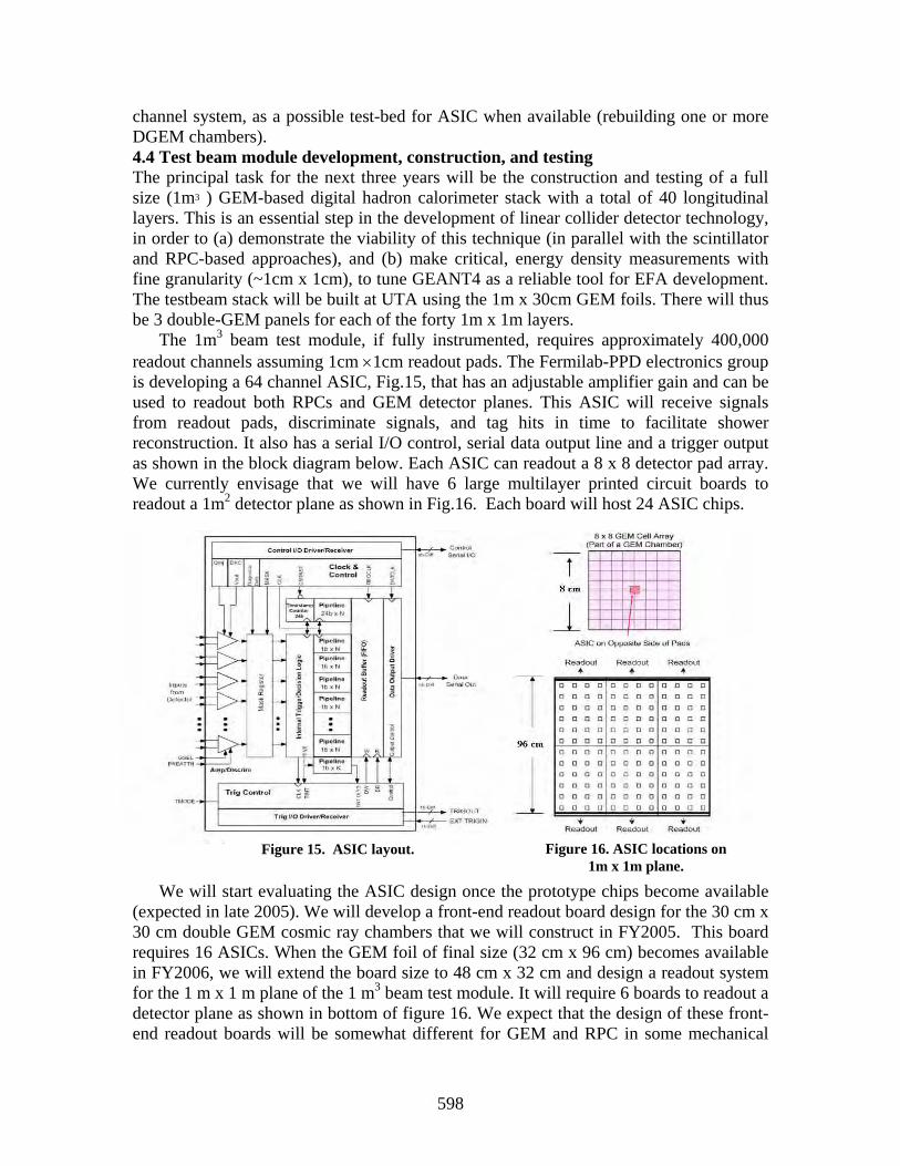
channel system, as a possible test-bed for ASIC when available (rebuilding one or more DGEM chambers). 4.4 Test beam module development, construction, and testing The principal task for the next three years will be the construction and testing of a full size (1m3 ) GEM-based digital hadron calorimeter stack with a total of 40 longitudinal layers. This is an essential step in the development of linear collider detector technology, in order to (a) demonstrate the viability of this technique (in parallel with the scintillator and RPC-based approaches), and (b) make critical, energy density measurements with fine granularity (~1cm x 1cm), to tune GEANT4 as a reliable tool for EFA development. The testbeam stack will be built at UTA using the 1m x 30cm GEM foils. There will thus be 3 double-GEM panels for each of the forty 1m x 1m layers.
The 1m3 beam test module, if fully instrumented, requires approximately 400,000 readout channels assuming 1cm ×1cm readout pads. The Fermilab-PPD electronics group is developing a 64 channel ASIC, Fig.15, that has an adjustable amplifier gain and can be used to readout both RPCs and GEM detector planes. This ASIC will receive signals from readout pads, discriminate signals, and tag hits in time to facilitate shower reconstruction. It also has a serial I/O control, serial data output line and a trigger output as shown in the block diagram below. Each ASIC can readout a 8 x 8 detector pad array. We currently envisage that we will have 6 large multilayer printed circuit boards to readout a 1m2 detector plane as shown in Fig.16. Each board will host 24 ASIC chips.
We will start evaluating the ASIC design once the prototype chips become available (expected in late 2005). We will develop a front-end readout board design for the 30 cm x 30 cm double GEM cosmic ray chambers that we will construct in FY2005. This board requires 16 ASICs. When the GEM foil of final size (32 cm x 96 cm) becomes available in FY2006, we will extend the board size to 48 cm x 32 cm and design a readout system for the 1 m x 1 m plane of the 1 m3 beam test module. It will require 6 boards to readout a detector plane as shown in bottom of figure 16. We expect that the design of these front-end readout boards will be somewhat different for GEM and RPC in some mechanical
Figure 15. ASIC layout. Figure 16. ASIC locations on 1m x 1m plane.
278598
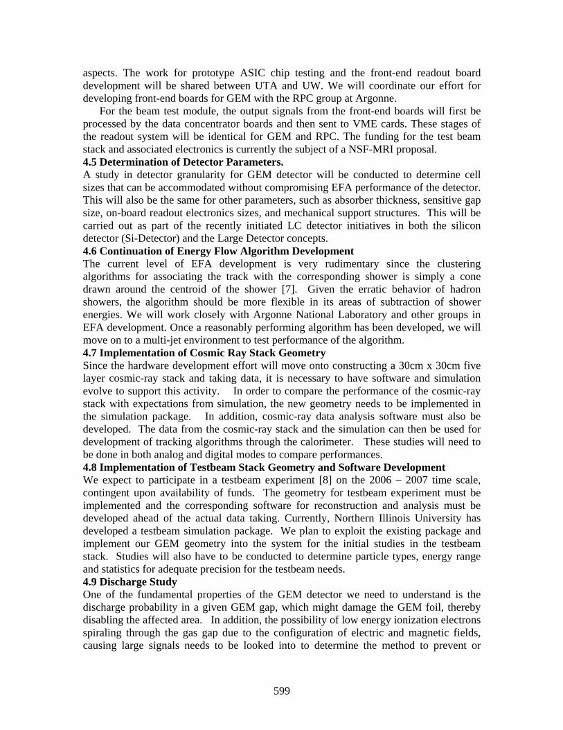
aspects. The work for prototype ASIC chip testing and the front-end readout board development will be shared between UTA and UW. We will coordinate our effort for developing front-end boards for GEM with the RPC group at Argonne.
For the beam test module, the output signals from the front-end boards will first be processed by the data concentrator boards and then sent to VME cards. These stages of the readout system will be identical for GEM and RPC. The funding for the test beam stack and associated electronics is currently the subject of a NSF-MRI proposal. 4.5 Determination of Detector Parameters. A study in detector granularity for GEM detector will be conducted to determine cell sizes that can be accommodated without compromising EFA performance of the detector. This will also be the same for other parameters, such as absorber thickness, sensitive gap size, on-board readout electronics sizes, and mechanical support structures. This will be carried out as part of the recently initiated LC detector initiatives in both the silicon detector (Si-Detector) and the Large Detector concepts. 4.6 Continuation of Energy Flow Algorithm Development The current level of EFA development is very rudimentary since the clustering algorithms for associating the track with the corresponding shower is simply a cone drawn around the centroid of the shower [7]. Given the erratic behavior of hadron showers, the algorithm should be more flexible in its areas of subtraction of shower energies. We will work closely with Argonne National Laboratory and other groups in EFA development. Once a reasonably performing algorithm has been developed, we will move on to a multi-jet environment to test performance of the algorithm. 4.7 Implementation of Cosmic Ray Stack Geometry Since the hardware development effort will move onto constructing a 30cm x 30cm five layer cosmic-ray stack and taking data, it is necessary to have software and simulation evolve to support this activity. In order to compare the performance of the cosmic-ray stack with expectations from simulation, the new geometry needs to be implemented in the simulation package. In addition, cosmic-ray data analysis software must also be developed. The data from the cosmic-ray stack and the simulation can then be used for development of tracking algorithms through the calorimeter. These studies will need to be done in both analog and digital modes to compare performances. 4.8 Implementation of Testbeam Stack Geometry and Software Development We expect to participate in a testbeam experiment [8] on the 2006 – 2007 time scale, contingent upon availability of funds. The geometry for testbeam experiment must be implemented and the corresponding software for reconstruction and analysis must be developed ahead of the actual data taking. Currently, Northern Illinois University has developed a testbeam simulation package. We plan to exploit the existing package and implement our GEM geometry into the system for the initial studies in the testbeam stack. Studies will also have to be conducted to determine particle types, energy range and statistics for adequate precision for the testbeam needs. 4.9 Discharge Study One of the fundamental properties of the GEM detector we need to understand is the discharge probability in a given GEM gap, which might damage the GEM foil, thereby disabling the affected area. In addition, the possibility of low energy ionization electrons spiraling through the gas gap due to the configuration of electric and magnetic fields, causing large signals needs to be looked into to determine the method to prevent or
279599
minimize this effect, if present. For this study, a new simulation program Garfield [9] is being implemented for this study since the current GEANT based simulation program we use, Mokka, does not allow this level of detailed studies. 4.10 World-wide Linear Collider Test Beam Coordination Yu has been asked to lead the American Linear Collider Test Beam working group. He has taken initiatives in putting together a report [10] on current World-wide LC testbeam effort and a planning document [8]. This report has been completed recently and been released to the World-wide LC community. This testbeam effort should continue in the next 2 – 4 years to help determine technological choices and the conceptual and technical design reports on both the LC detector initiatives. 5.0 Timeline for proposed work FY05 - 30cm x 30cm detector stack - Develop test 1m x 30cm foils - Prototype run of ASIC and its testing
- NSF- MRI start of 1m3 test beam GEM module development and construction - GEM, SPICE, Garfield and Test Beam simulations FY06 - Completion of 1m3 test beam GEM module - Begin program of GEM/RPC beam tests - Further EFA development FY07 - Further beam tests, data analysis, GEM-DHCAL calorimeter system design 6.0 Facilities, Equipment, and Computing Resources The UTA HEP group has a 10,000 ft2 detector construction facility, an excellent mechanical workshop, and a very high performance parallel computing farm. In late 2005 these facilities will be integrated as part of a new $40M Physics and Chemistry Research building. 7.0 Budget and Discussion The budget request is given in the table below. Personnel We request support for a post-doctoral associate for six months, for each of the three years. The UTA postdoctoral fellow supported will be Dr. Jia Li who has been working on our GEM prototypes, drawer assembly techniques, and calorimeter module design. We also request support for two months of engineering support in FY05 at UW for electronics design and development for the cosmic stack. We request support for a graduate student in FY06-07 to work on the testbeam stack, and analysis of data from the testbeam.
ITEM FY05 FY06 FY07
0.5 Postdoc 21000 22050 23152.5Fringe 6300 6615 6945.75Engineer (2 months) 11500Fringe 3450Graduate student 21600 22680Fringe 9720 10206Cosmic Ray Teststand 10,000Discriminator Boards 6,000Travel 8000 8000 8000Materials and Supplies 10000 5000 5000Direct costs 76250 72985 75984.25Indirect costs 28920 35032.8 36472.44TOTAL 105170 108017.8 112456.7
280600

Equipment We request support to construct the cosmic ray test stand to be used with the stack of five 30cm x 30cm double-GEM chambers. We also request support for the discriminator boards for the same setup to be developed at UW. Travel For each year we request a limited amount of travel support to attend Linear Collider Workshops and meetings, during this development phase for the Linear Collider Detector. We also request support for one foreign trip each year to attend the LCWS conference or meeting(s) of the CALICE collaboration [11], of which UTA is a member. We have specific responsibilities that involve travel as follows: (1) Andrew White is the U.S. CALICE Steering Board representative, and (2) Jae Yu is the chairperson of the CALICE Technical Board, and the ALCPG testbeam coordinator. 9.0 Broader Impact This project has already had an impact in a number of areas. Two graduate students have obtained MS degrees with the studies on GEM detector performances and EFA development using simulated data. Currently, four undergraduate students are working on prototype development and simulations.
Andrew White and a UTA condensed matter colleague have developed a high resolution Positron Emission Tomography system using GEM foils that is the subject of a patent application. We are also discussing the possible applications of GEM foils in very large area radiation detectors for homeland security applications.
UTA has an active Quarknet educational program that has evolved into an expanding program of installing cosmic ray detectors in local high schools. We are currently using scintillation counters, but anticipate having students work with GEM foils once they are made for our project in larger quantities. The students we are working with are drawn from the Hispanic population of Fort Worth, Texas in an effort to increase the number of such students pursuing careers in science. 10.0 References 1. F. Sauli, Nucl. Inst. Meth., A386, 531 (1997). 2. ALEPH Collaboration, Nucl. Inst. Meth. A360, 481 (1995); 3. Mokka Home Page, http://polype.in2p3.fr/geant4/tesla/www/mokka/mokka.html 4. GEANT4, detector simulation toolkit, http://geant4.web.cern.ch/geant4/ 5. F. Richard, et al., TeV Energy Superconducting Linear Accelerator (TESLA)
Technical Design Report, (2001); http://tesla.desy.de/new\_pages/TDR_CD/start.html 6. S. Habib, “Simulation Studies of a New Digital Hadron Calorimeter, Using Gas
Electron Multipliers (GEM)", MS Thesis, University of Texas at Arlington, UTA-HEP/LC-003, Unpublished (2003).
7. V. Kaushik, “Performance of Novel Digital Hadron Calorimeter Using Gas Electron Multiplier (GEM) and the Energy Flow Algorithm Development,” MS Thesis, University of Texas at Arlington, UTA-HEP/LC-004, Unpublished (2004).
8. J. C. Brient, J. Yu et al., World-wide Linear Collider Test Beam Working Group, “International Linear Collider Calorimeter Test Beam Program (A Planning Document for Use of Test Beam Facility at Fermilab,” FNAL-TM-2291, In preparation (2005).
9. R. Veenhof, Simulation of gaseous detectors, http://consult.cern.ch/writeup/garfield/ 10. Linear Collider Test Beam Working Group, http://www-
lc.fnal.gov/lc_testbeams/wwlctb_working_group.pdf (2004) 11. CALICE Collaboration, http://polywww.in2p3.fr/flc/calice.html
281601

6.9
6.9
Calorimetry
6.9: Development of Particle-Flow Algorithms and Simulation Software for the
ILC Detector(s)
(renewal)
Calorimetry
Contact person Dhiman Chakraborty
[email protected] (630) 840-8569
Institution(s)
Argonne Fermilab
Iowa NIU
Oregon SLAC
U.T. Arlington
Funds awarded (DOE) FY04 award: 35,000
New funds requested FY05 request: 94,200
FY06 request: 154,900 FY07 request: 156,800
282602
Proposal Name
Development of Particle-Flow Algorithms and Simulation Software for the ILC Detector(s)
Classification (Detector)
Calorimeter: simulation software and algorithm development.Note: Much of the proposed work, especially those on simulation software, span across all detectorsubsystems, and should really be considered in the broader premise of “Full Detector”. In the absenceof such a category, we have chosen to put this proposal under “calorimeter”, since our involvement insimulation and other software tasks stem from our interest in developing new algorithms for calorimetry.
Personnel and Institution(s) requesting funding
G. Blazey, D. Chakraborty, J. G. Lima, J. McCormick, R. McIntosh, V. Zutshi.Northern Illinois Center for Accelerator and Detector Development, Northern Illinois University [1]
Collaborators
S. Magill et al., Argonne National Laboratory,N. Graf et al., Stanford Linear Accelerator Center,C. Milstene et al., Fermi National Accelerator Laboratory,R. Frey et al., University of Oregon,J. Yu et al., University of Texas at Arlington,G. Wilson et al., University of Kansas,U. Mallik et al., University of Iowa,The CALICE collaboration.[2]
Project Leader
Dhiman [email protected](815)753-8804, (630)840-8569, (630)452-6368
Project Overview
The Northern Illinois University(NIU)/Northern Illinois Center for Accelerator and Detector Devel-opment (NICADD) group is interested in calorimeter R&D for the proposed ILC.[1] We propose todevelop, in simulation and in prototype, designs for a hadron calorimeter (HCal) optimized for jetreconstruction using particle-flow algorithms (a.k.a. “energy-flow algorithms”). Simulation/algorithmdevelopment and hardware prototyping are envisaged as the two main components of our efforts. Thisproposal addresses the first component while the second is the subject of a separate proposal.
An e+e− linear collider is a precision instrument that can elucidate Standard Model (SM) physics nearthe electroweak energy scale as well as discover new physics processes in that regime, should they exist.In order to fully realize the potential anticipated from a machine of this type, the collection of standardhigh energy physics detector components comprising an experiment must be optimized, sometimes inways not yet realized at current experiments. One such example is the hadron calorimeter which willplay a key role in measuring jets from decays of vector bosons and other heavy particles such as the topquark, the Higgs boson(s), etc. In particular, it will be important to be able to distinguish, in the finalstate of an e+e− interaction, the presence of a Z or a W boson by its hadronic decay into 2 jets. Thismeans that the dijet mass must be measured within ∼ 3 GeV, or, in terms of jet energy resolution,σ(E) ≈ 0.3
√E (E in GeV). Such high precision in jet energy measurement cannot be achieved by any
existing calorimeter in the absence of a kinematically overconstrained event topology. Similar precisionin measurements of jet and missing momentum will be crucial for discovery and characterization ofseveral other new physics processes as well as for precision tests of the Standard Model. Such ambitious
283603

objectives place strong demands on the performance of the calorimeters working in conjunction withthe tracking system at the ILC, and requires development of new algorithms and technology.
The most promising means to achieving such unprecedented jet energy resolutions is through particle-flow algorithms (PFA). A PFA attempts to separately identify in a jet its charged, electromagnetic,and neutral hadron components, in order to use the best means to measure each. On average, neutralhadrons carry only ∼11% of a jet’s total energy, which can only be measured with the relativelypoor resolution of the HCal. The tracker is used to measure with much better precision the chargedcomponents (∼64% of jet energy), and the electromagnetic calorimeter (ECal) to measure the photonswith σ(E) ≈ 0.15
√E (∼24% of jet energy). The left panel of Fig. 1 shows the momentum distribution
of particles in a representative multijet physics process of interest. On average, only a small fraction ofa jet’s energy is carried by particles with momenta greater than 20 GeV. The right panel of Fig. 1 showsthe precisions of energy measurement by a calorimeter, and momentum measurement by a tracker, ofsingle charged hadrons, as functions of their momenta in one nominal detector design. Measurementsfrom the tracker are at least two orders (one order) of magnitude more precise than those from thecalorimeter for particles below 20 GeV (100 GeV). A net jet energy resolution of σ(E) ≈ 0.3
√E is
thus deemed achievable by using the HCal only to measure the neutral hadrons with σ(E) ≈ 0.6√
E.However, this will certainly require extensive and simultaneous optimization of detector design andtuning of algorithm parameters.
Figure 1: Left: the momentum distribution of particles in e+e− → ZZ → 4 jets events at√
s = 500 GeV.Right: the fractional energy (momentum) resolution of an excellent calorimeter and that of a good trackeras functions of particle momentum.
A calorimeter designed for PFAs must be finely segmented both transversely and longitudinally for3-d shower reconstruction, separation of neutral and charged clusters, and association of the chargedclusters to corresponding tracks. This requires realistic simulation of parton shower evolution andof the detector’s response to the particles passing through it. Accurate simulation relies heavily onanalysis of data from beam test of prototype modules. The detector optimization requires the sim-ulation, visualization, and analysis packages to be highly flexible, which calls for careful design andimplementation of the software itself.
Very large numbers of events will have to be simulated to evaluate competing detector designs vis-a-visILC physics goals. Characterization of signatures arising from processes predicted by some extensionsof the SM will require simultaneous coverage of broad ranges of undetermined parameters. Parame-trized fast simulation programs will thus have to be developed once the algorithms have stablized.Parametrization of PFAs will require much work, and is one of our key objectives.
284604

Broader Impact
The impact of the proposed research is not limited to calorimetry at the ILC. Lessons learnt from thisexperience are likely to prove valuable at other future Experimental High Energy experiments as well.
We have had good success so far in involving young students from different disciplines in our R&Dactivities, which we consider an important aspect of our research program. Indeed, much of theinitial coding for the full-detector simulation program and most of that for the test-beam modulesimulation program described in the next section were done by MS students, Mr. McIntosh and Mr.McCormick, respectively. While Mr. McIntosh has subsequently decided to continue with our group,Mr. McCormick, a Computer Science major, has taken up a joint appointment co-funded by NICADDand SLAC to work full-time as a staff programmer on ILC detector simulation software development.Our group represents an excellent mix of individuals from different national origins, and we seekparticipation from the widest possible spectra of gender, ethnicity, geographic origin, and levels ofphysical ability.
Inter-institutional collaboration, within the US as well as across national boundaries, is a fundamentalrequirement for a project of this nature and magnitude to succeed. We have come to appreciateearly the value of sharing not only the results, but all source code, usage instructions, and data filesfreely. All of the results described in the next section are carefully documented on our web page, withcomplete instructions for installing and running the simulation software, examples, and sample datafiles.[1] Furthermore, we are committed to entertaining requests for simulation jobs from any potentialuser.[3] Indeed, our group is responsible for maintaining the production version of the current ALCPGstandard detector simulation program, and the primary provider of benchmark samples, as well asspecial requests for the entire American LC community. This reflects our strong commitment tofostering the spirit of collaborative networking and inter-institutional partnership among all users.Some of the funds requested in the 2nd and 3rd years will be used to enhance our capability to producelarge volumes of simulated data in response to the anticipated increase in demands from the users.
NIU has an active outreach program with a dedicated coordinator. Activities include visits to schoolsand civic organizations in the region and hosting open house events to promote public awareness andinterest in science. The presentations, which usually include demonstrations, highlight the importanceof fundamental scientific research and give the audience a glimpse of techniques used in experimentationand interpretation of data. Attendance at these presentations exceeds 10,000 per year. Members ofour team also volunteer in Fermilab’s “Ask-a-Scientist” program and similar events offered throughNIU’s outreach web site.
Results of Prior Research
Members of NIU, ANL, SLAC, and UTA began collaborating on PFAs, simulations, and softwaredevelopment efforts in January, 2002. Several other groups have since joined the effort, and links havebeen established with European colleagues who had been active in this area already. The results thatemerged through discussions at our regularly scheduled meetings have been presented at the Calorconferences, ECFA and ACFA meetings, the American LC workshops, and at the International LCPhysics and Detector Workshops.
Toward the optimization of the HCal design, the NIU and ANL teams have started investigating bothanalog (cell energy measurements) and digital (hit density measurements) methods as functions of thecell size. Our preliminary findings suggest that with sufficiently small cells, the digital method yieldsa more precise measurement of the hadron energy, i.e., fluctuations in hit density are smaller thanthose in the sampled energy of a hadronic shower. Use of local hit density in lieu of the depositedenergy to weigh the calorimeter hits results in superior energy resolution and lateral containment ofsingle hadron showers. Two independent approaches to the implementation of a PFA have helpedimprove our understanding of the optimal cell sizes and geometry for best charged/neutral hadronshower separation in jets within the context of some specific overall detector parameters.
285605
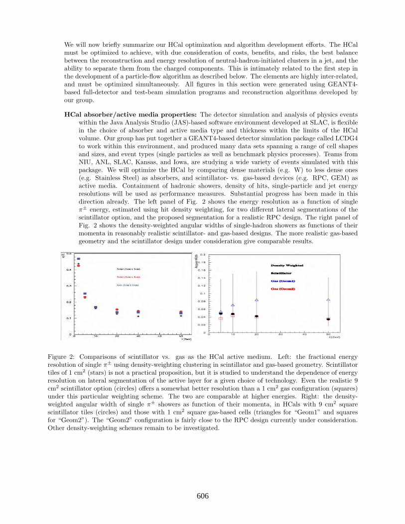
We will now briefly summarize our HCal optimization and algorithm development efforts. The HCalmust be optimized to achieve, with due consideration of costs, benefits, and risks, the best balancebetween the reconstruction and energy resolution of neutral-hadron-initiated clusters in a jet, and theability to separate them from the charged components. This is intimately related to the first step inthe development of a particle-flow algorithm as described below. The elements are highly inter-related,and must be optimized simultaneously. All figures in this section were generated using GEANT4-based full-detector and test-beam simulation programs and reconstruction algorithms developed byour group.
HCal absorber/active media properties: The detector simulation and analysis of physics eventswithin the Java Analysis Studio (JAS)-based software environment developed at SLAC, is flexiblein the choice of absorber and active media type and thickness within the limits of the HCalvolume. Our group has put together a GEANT4-based detector simulation package called LCDG4to work within this environment, and produced many data sets spanning a range of cell shapesand sizes, and event types (single particles as well as benchmark physics processes). Teams fromNIU, ANL, SLAC, Kansas, and Iowa, are studying a wide variety of events simulated with thispackage. We will optimize the HCal by comparing dense materials (e.g. W) to less dense ones(e.g. Stainless Steel) as absorbers, and scintillator- vs. gas-based devices (e.g. RPC, GEM) asactive media. Containment of hadronic showers, density of hits, single-particle and jet energyresolutions will be used as performance measures. Substantial progress has been made in thisdirection already. The left panel of Fig. 2 shows the energy resolution as a function of singleπ± energy, estimated using hit density weighting, for two different lateral segmentations of thescintillator option, and the proposed segmentation for a realistic RPC design. The right panel ofFig. 2 shows the density-weighted angular widths of single-hadron showers as functions of theirmomenta in reasonably realistic scintillator- and gas-based designs. The more realistic gas-basedgeometry and the scintillator design under consideration give comparable results.
Figure 2: Comparisons of scintillator vs. gas as the HCal active medium. Left: the fractional energyresolution of single π± using density-weighting clustering in scintillator and gas-based geometry. Scintillatortiles of 1 cm2 (stars) is not a practical proposition, but it is studied to understand the dependence of energyresolution on lateral segmentation of the active layer for a given choice of technology. Even the realistic 9cm2 scintillator option (circles) offers a somewhat better resolution than a 1 cm2 gas configuration (squares)under this particular weighting scheme. The two are comparable at higher energies. Right: the density-weighted angular width of single π± showers as function of their momenta, in HCals with 9 cm2 squarescintillator tiles (circles) and those with 1 cm2 square gas-based cells (triangles for “Geom1” and squaresfor “Geom2”). The “Geom2” configuration is fairly close to the RPC design currently under consideration.Other density-weighting schemes remain to be investigated.
286606

HCal transverse granularity/Longitudinal segmentation: We plan to optimize the 3-d granu-larity of cells for the most promising PFAs vis-a-vis the active medium technology (see the leftpanel of Fig. 2) The methods developed here are generalizable to different total detector geome-tries, i.e., SiD (which uses silicon wafers for tracking), LD (which uses TPCs for tracking), etc. Thebasic performance measure here is the ability to separate showers initiated by charged and neutralhadrons - the key to any PFA. Indeed, if all the cell energies in a jet could be fully separated andcorrectly assigned to the parent particle, then a jet energy resolution of σ(E) ≈ 0.15
√E (E in
GeV) could be achieved. It turns out that the limiting factor in the overall jet energy resolution isthe confusion term arising from imperfect association due to finite granularity and misassignment.From the reconstruction algorithm’s point of view, it is this term that poses the biggest challenge.
Analog vs. digital readout for the HCal: The question of optimal 3-d granularity is intimatelyrelated to that of the readout method, which needs to be evaluated by comparing jet resolutionswith both analog and digital readout. At the extreme, “digital” readout means a single-bit“yes/no” decision on whether or not a minimum ionizing particle (MIP) has passed through a givencell. Since such digital measurements are less susceptible to Landau and path-length fluctuationsthan full (12-15 bit) analog measurements, hit counting has smaller spread than energies samplesin the active medium. We have shown that for small cell sizes (< 10 cm2), the number of cellshit is a superior estimator of energy of single hadrons below 20 GeV (where more than 95% ofthe particles in typical jets in multijet events of interest are concentrated) to traditional analogsampling. Since the spatial spread of a shower increases in a less-than-linear proportion to itsenergy, the advantage gradually disappears at higher energies. We find that a semi-digital readoutallowing multiple thresholds to classify the hit status of a cell can be effectively used counter thisnon-linearity. This supports the contention that the dynamic range sacrificed in order to achievefiner segmentation is not likely to hurt us at all.
Figure 3: The fractional resolution of single π± energy using full analog (circles), 1-bit digital (squares), and2-bit digital (triangles) read-outs. We find that 3 thresholds (i.e. 2-bits) is optimal.
It may be prudent to consider both the best analog and the best digital version of the HCalfor eventual evaluation with test beams provided both prove potentially capable of meeting theenergy resolution requirement. Such testing could spur future advances in readout technology.
287607
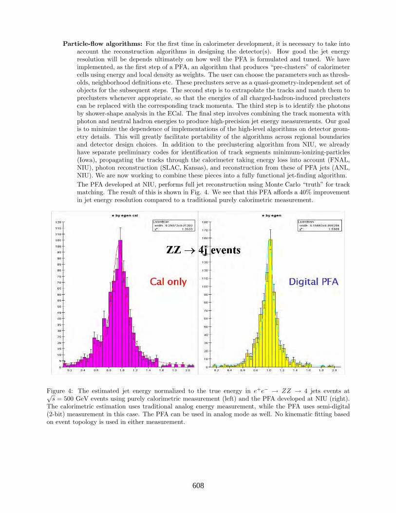
Particle-flow algorithms: For the first time in calorimeter development, it is necessary to take intoaccount the reconstruction algorithms in designing the detector(s). How good the jet energyresolution will be depends ultimately on how well the PFA is formulated and tuned. We haveimplemented, as the first step of a PFA, an algorithm that produces “pre-clusters” of calorimetercells using energy and local density as weights. The user can choose the parameters such as thresh-olds, neighborhood definitions etc. These preclusters serve as a quasi-geometry-independent set ofobjects for the subsequent steps. The second step is to extrapolate the tracks and match them topreclusters whenever appropriate, so that the energies of all charged-hadron-induced preclusterscan be replaced with the corresponding track momenta. The third step is to identify the photonsby shower-shape analysis in the ECal. The final step involves combining the track momenta withphoton and neutral hadron energies to produce high-precision jet energy measurements. Our goalis to minimize the dependence of implementations of the high-level algorithms on detector geom-etry details. This will greatly facilitate portability of the algorithms across regional boundariesand detector design choices. In addition to the preclustering algorithm from NIU, we alreadyhave separate preliminary codes for identification of track segments minimum-ionizing-particles(Iowa), propagating the tracks through the calorimeter taking energy loss into account (FNAL,NIU), photon reconstruction (SLAC, Kansas), and reconstruction from these of PFA jets (ANL,NIU). We are now working to combine these pieces into a fully functional jet-finding algorithm.The PFA developed at NIU, performs full jet reconstruction using Monte Carlo “truth” for trackmatching. The result of this is shown in Fig. 4. We see that this PFA affords a 40% improvementin jet energy resolution compared to a traditional purely calorimetric measurement.
Figure 4: The estimated jet energy normalized to the true energy in e+e− → ZZ → 4 jets events at√s = 500 GeV events using purely calorimetric measurement (left) and the PFA developed at NIU (right).
The calorimetric estimation uses traditional analog energy measurement, while the PFA uses semi-digital(2-bit) measurement in this case. The PFA can be used in analog mode as well. No kinematic fitting basedon event topology is used in either measurement.
288608

The NIU group has also made significant contributions to LC detector simulation software during thepast 3 years. We ported and have been maintaining all of the current American software on the Linuxplatform. Since mid-2002, we have been processing simulation requests from several groups engaged inLC R&D, on Linux farms at NIU and FNAL. We organized a workshop at NIU/NICADD in November,2002 (http://nicadd.niu.edu/ws/), to bring the groups together, chart a plan, and set out in anorganized manner. This was followed by similar workshops at SLAC in 2003 and at ANL in 2004.Following are the simulation software projects where we have made substantial progress and hope toremain commited:
Simulation of full detector concepts: We have developed, in close collaboration with our col-leagues at SLAC, a stand-alone GEANT4-based simulation package. This package, named “LCDG4”,fully complies with the model put forth by the ALCPG simulation group, and adds several usefulfunctionalities to it.[4] It produces “raw” hit output in the globally accepted LCIO format andsupports projective geometries in θ, φ, as well as non-projective ones with cells of constant lineardimensions. After extensive testing, this package has been adopted as the standard for ALCPG.Figure 5 shows an example event display from LCDG4.
Figure 5: Side view (left) and end view (right) of an e+e− → tt→ e + ν+ 4 jets event at√
s = 500 GeV inthe SD detector simulated using the LCDG4 program developed at NIU.
Simulation of test-beam prototype modules: Further, as members of the CALICE collaboration(CAlorimeter for the LInear Collider with Electrons,[2]), and in active cooperation with ourEuropean colleagues, we have produced a GEANT4-based simulator for the detector prototypemodule that is expected to be exposed to test beams at Fermilab over a period of 3 years startingin mid-2005. This program, called “TBMokka” is built on an alternative simulation frameworkcalled “Mokka”, developed independently by our European colleagues. Figure 6 shows an exampleevent display from a stand-alone GEANT4-based program to simulate a test-beam module (thisprogram is used as a cross-check for TBMokka).[5]We are well on our way to combining the best features of LCDG4 and Mokka. The new “nextgeneration” simulation program incorporates a more advanced XML-based geometry descriptionsystem. Like its predecessors, it supports run-time geometry specification, but offers a widerrange of options and easier changes to geometries using GDML (Geometry Description Mark-upLanguage), a Geant4-specific extension of XML (eXtensible Mark-up Language).
289609
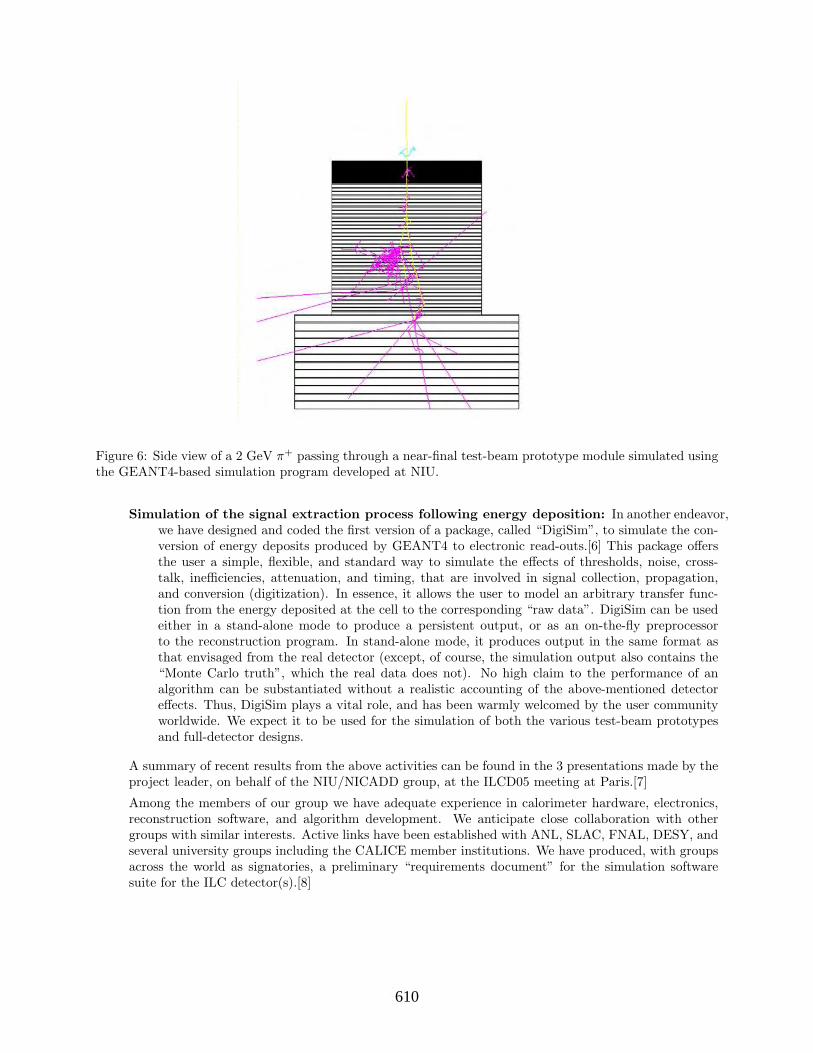
Figure 6: Side view of a 2 GeV π+ passing through a near-final test-beam prototype module simulated usingthe GEANT4-based simulation program developed at NIU.
Simulation of the signal extraction process following energy deposition: In another endeavor,we have designed and coded the first version of a package, called “DigiSim”, to simulate the con-version of energy deposits produced by GEANT4 to electronic read-outs.[6] This package offersthe user a simple, flexible, and standard way to simulate the effects of thresholds, noise, cross-talk, inefficiencies, attenuation, and timing, that are involved in signal collection, propagation,and conversion (digitization). In essence, it allows the user to model an arbitrary transfer func-tion from the energy deposited at the cell to the corresponding “raw data”. DigiSim can be usedeither in a stand-alone mode to produce a persistent output, or as an on-the-fly preprocessorto the reconstruction program. In stand-alone mode, it produces output in the same format asthat envisaged from the real detector (except, of course, the simulation output also contains the“Monte Carlo truth”, which the real data does not). No high claim to the performance of analgorithm can be substantiated without a realistic accounting of the above-mentioned detectoreffects. Thus, DigiSim plays a vital role, and has been warmly welcomed by the user communityworldwide. We expect it to be used for the simulation of both the various test-beam prototypesand full-detector designs.
A summary of recent results from the above activities can be found in the 3 presentations made by theproject leader, on behalf of the NIU/NICADD group, at the ILCD05 meeting at Paris.[7]
Among the members of our group we have adequate experience in calorimeter hardware, electronics,reconstruction software, and algorithm development. We anticipate close collaboration with othergroups with similar interests. Active links have been established with ANL, SLAC, FNAL, DESY, andseveral university groups including the CALICE member institutions. We have produced, with groupsacross the world as signatories, a preliminary “requirements document” for the simulation softwaresuite for the ILC detector(s).[8]
290610

The steady progress that we have achieved so far has been made possible by funding received receivedfor this purpose during the past 3 fiscal years from DOE and NSF, in addition to generous, but lessspecific, funding from the Department of Education. In FY 2002 we received $45K from the DOEunder its Advanced Detector Research program. An exploratory grant of $8.5K was awarded by theNSF in following year. Finally, last year (FY2004) we were awarded $35K for our simulation softwareand algorithm development activities.
Activities outlined in this proposal are synergistic with the proposals for hardware prototyping ofdifferent technology choices. We will continue to remain in close contact with the groups involved inhardware development for the ECal and the HCal.
Facilities, Equipment and Other Resources
The funding requested here will be augmented by the following support, totaling approximately $500K,from other sources:
(a) NIU/NICADD personnel,
(b) ANL/SLAC personnel,
(c) Computing hardware and support provided by NICADD,
(d) 40-CPU Fermilab Linux farm (run by NIU personnel). These machines are relatively old, withper-CPU-capacity roughly a fifth of those requested in this proposal.
FY2005 activities and deliverablesDuring the first year we will concentrate on two things. First, design and development of well-structuredPFAs that can be easily ported across detector design details, as described before. Both analog anddigital versions (for the hadronic section) of the algorithms, which give encouraging preliminary results,will be further investigated and optimized. Second, completion of the DigiSim package so the algorithmscan be tuned on input that closely resembles real data. Beam test will provide an opportunity tounderstand not only the detector hardware, but the simulation and reconstruction software as well.
The first year deliverable will be a first version of a class of particle-flow algorithms based on fullsimulation and reconstruction of the calorimeter and the tracking system. In addition, the standardGEANT4-based simulation facility (farm+server) will be available for to the entire ILC communitythrough a web-based request form.[3] Also, the TBMokka simulator will be finalized during this period.
FY2006 activities and deliverablesApart from extensive tuning of the algorithms, comprehensive studies of critical physics processes willhave to be carried out in order to understand the impact of the calorimeter performance on the physicsprogram of the Linear Collider. These studies will employ both the analog and digital versions of ourPFAs. The second year deliverables will be further development of PFA-based jet-reconstruction anda detailed assessment of physics reach vs calorimeter performance for the ILC with a clear statementon the desirability of a digital or analog option for the hadronic calorimeter.
FY2007 activities and deliverablesIn the third year we will embark on the development of parameterized simulations of the particle-flowalgorithms. The technology and geometry are expected to have been narrowed down by that timesetting the stage for such parametrized fast simulation for extensive physics studies. By the end ofthe third year we expect to produce, in collaboration with other groups, a fast simulation programbased on PFAs. In addition, extensive benchmarking of critical physics processes, as well as evolutionof pattern-recognition and reconstruction algorithms will continue.
291611

Budget justificationThe first year’s activities revolve around the development of particle-flow algorithms and simulation.This will involve NICADD staff members (not included in the budget shown here), and 1.0 FTE post-doctoral associate. Optimization and detailed performance studies of the algorithm will be carried outin the second year by 1.0 FTE graduate student and 1.0 FTE post-doc with additional support fromNICADD staff. During the third year, the development of parameterized simulations will be supportedby 1.0 FTE post-doc, together with 1.0 FTE graduate students. Communication of progress andexchange of ideas through international workshops and conferences will be crucial for our endeavor tohave a global impact. We estimate four domestic trips at $1.5K each and two international trips at$2.0K each during the first year, and 1.5 times as many in the second and third years. The equipmentcost accounts for a 20-CPU Linux mini-farm + file server which will be needed in early FY06 toaugment the allocation from Fermilab, as the simulation service enters a serious production phase.This additional capacity will have to be doubled toward the end of FY 2007.
Fringe benefits to personnel at NIU’s mandated rate of 52% of salary, and indirect costs at the off-siterate of 26% (instead of the usual 45%, since the requested personnel will work in offices at Fermilaballocated specifically for ILC R& D) are included in the requested amount.
Three-year budget, in then-year K$
Item FY2005 FY2006 FY2007 TotalPost-doctoral Associates 41.0 42.2 43.5 126.7
Graduate Students 0 21.0 21.8 42.8Undergraduate Students 0 0 0 0Total Salaries and Wages 41.0 63.2 65.1 169.3
Fringe Benefits 23.8 24.5 25.2 73.5Total Salaries, Wages and Fringe Benefits 62.7 85.5 90.3 238.5
Equipment 0 25.0 23.0 48.0Travel 10.0 15.4 15.9 41.3
Other direct costs 0 0 0 0Total direct costs 74.8 128.1 129.2 332.1
Indirect costs (26% of non-equipment) 19.4 26.8 27.6 73.8Total direct and indirect costs 94.2 154.9 156.8 405.9
References
[1] The NICADD web page, presentations, documents: http://nicadd.niu.edu/ andhttp://nicadd.niu.edu/research/lcd/,
[2] http://polywww.in2p3.fr/flc/calice.html,
[3] http://nicadd.niu.edu/∼jeremy/lcd/simreq/,
[4] http://nicadd.niu.edu/∼lima/lcdg4/,
[5] http://nicadd.niu.edu/∼jeremy/lcd/tbeam/,
[6] http://nicadd.niu.edu/digisim/DigiSim.html,
[7] http://polywww.in2p3.fr/actualites/congres/ilcd2005/,
[8] The ILC detector Simulation Requirements document: http://forum.linearcollider.org/ → “FullSimulations” → “Simulation Requirements Document”.
292612

6.10
6.10
Calorimetry
6.10: Investigation of ECAL Concepts Designed for Particle Flow
(new proposal)
Calorimetry
Contact person Graham Wilson
[email protected] (785) 864-5231
Institution(s)
Kansas
New funds requested FY05 request: 30,000
FY06 request: 0 FY07 request: 0
293613

Investigation of ECAL Concepts Designed for Particle Flow
Classification (subsystem)
Detector: electromagnetic calorimeter (barrel, endcap, low-angle)
Personnel and Institution(s) requesting funding
Eric Benavidez, Darius Gallagher, Carsten Hensel, Jonathan van Eenwyk and Graham W.Wilson, Department of Physics and Astronomy, University of Kansas, Lawrence, KS 66045
Collaborators
We have listed the names of various people with whom we have been in discussion withregarding participation in this and related projects.
Project Leader
Graham W. [email protected]; [email protected](785)-864-5231
Project Overview
The project goal is to investigate electromagnetic calorimeter (ECAL) design concepts suitedto the linear collider physics program. The principal physics design criteria for the ECALare i) hermeticity ii) the precise measurement of jet energies using particle flow and iii) adesign suited to a general purpose experiment. All these criteria are closely tied to the overalldetector design concept, and therefore this project is being coordinated with the detectordesign studies. In the following sections we outline some of the reasons for highlighting thesecriteria and discuss their impact on the ECAL concept.
[Hermeticity] For e+e− center-of-mass energies beyond mZ , physics processes with W’sor Z’s decaying in channels with 1 or 2 neutrinos occur frequently. Potential new physics suchas supersymmetry leads to final states with characteristic missing transverse momentum. Aprincipal detector goal is that events with significant missing transverse momentum shouldnot be faked by Standard Model processes without neutrinos. It is of paramount concern thathigh transverse momentum particles, particularly photons, are detected with zero inefficiency.In the very forward region, (nearer the beam than the forward tracking), extremely efficientdetection of electrons from two-photon processes is mandatory. It can also be necessary todetect muons and mips in such regions depending on the event topology.
The hermeticity requirements influence the ECAL design as follows: (i) need to avoid pointingcracks (ii) requirement to detect minimum ionizing particles (iii) elimination of “intruders”such as cosmics and halo muons (iv) reasonably uniform performance over the complete solidangle
[Particle Flow] In the particle flow method of jet energy measurement [1], the ECAL isused to measure the energy, polar angle and azimuth of photons in hadronic jets. A majorrequirement is to avoid double-counting of charged particles and photons in the visible energymeasurement. This is most easily achieved by placing the ECAL at large radius.
The essential issue for the ECAL is measuring the 3-momenta of the photons over a dynamicrange of between about 100 MeV and 500 GeV.
294614
We have studied the intrinsic contribution to jet energy resolution arising from electromag-netic energy resolution [2] and we confirm that fractional energy resolution of ≈ 10%/
√
E isnecessary in order to not appreciably degrade the potential jet energy resolution of 18%/
√
E.For a realistic particle flow algorithm in a detector where the overall jet energy resolutionattains 30%/
√
E, we expect this resolution would be dominated by confusion issues, andone could consider relaxing the electromagnetic energy resolution requirement substantially(perhaps by a factor of two) if jet energy resolution was the only physics concern (it isn’t !).
The measurement of τ -lepton decays places severe constraints on the separation of chargedhadrons from photons from π0 decay. Kinematic reconstruction of events containing τ -leptonsplaces rather stringent demands on the ECAL. (HCAL is relatively unimportant since neu-trons are absent and K0
Lare rare).
Another aspect of the calorimeter design which should not be overlooked is the detectionand measurement of hadronic jets in the forward region where the charged particle trackingis likely to be compromised, specialized functions need to be accommodated (eg. Bhabhaacolinearity measurement, luminosity measurement), and in general the environment is lessconducive to full reconstruction (pile-up from γγ events).
[Design suited to general purpose e+e− experiment] Detection and precision measure-ments of electrons and photons is an essential element of an e+e− experiment. The measure-ment of Bhabha’s and the e+e− → γγ process are part of the basic program and are expectedto play an important role in the measurement of absolute luminosity and the differential lu-minosity spectrum. Photons from initial and final-state radiation are often crucial aspects todoing some of the physics. With the prevalence of “radiative-return” events and events fromtwo-photon interactions, the tagging of the initial-state photon or a scattered electron canbe essential to physics analyses. ``γ events will be a useful cross-check of the center-of-massenergy determination.
Given that we don’t know what new physics will be explored at the linear collider, there is littlestrong guidance on the required energy resolution for the ECAL. One scenario which deservesmore investigation, as it is one of the more compelling constraints on the ECAL resolution, isthe measurement of the Higgs branching ratio to γγ presuming a Higgs mass of around 120GeV. This was studied in [3]. The best measurement will come from the WW fusion channel(e+e− → νeνeγγ) at the highest center-of-mass energy which has to compete against a largenon-Higgs Standard Model background. This measurement would be complementary to LHCbecause together with other channels the BR could be measured directly. For similar reasonsto LHC, the ECAL mass resolution directly influences the measurement precision. For thiskind of application, the constant term in the energy resolution can be just as important asthe stochastic term, and so an ECAL design which minimizes non-uniformities and can beeasily calibrated is important.
Detector Design Considerations relevant to ECAL
The final detector designs will be heavily influenced by the choices made for the calorimetry.Some of the main design parameters which need to be considered are: the chosen B-field, theinner radius of the ECAL, the radius of the coil, and the aspect ratio (ie. the polar angle atwhich to change from a barrel to an endcap geometry).
Much of the current ECAL effort has been directed to applying the principles used verysuccessfully in the limited solid angle LEP/SLC Silicon-Tungsten ECALs used for luminositymeasurements to a full solid angle detector [4]. This approach is very attractive. Existing
295615
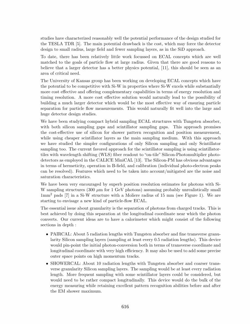
studies have characterized reasonably well the potential performance of the design studied forthe TESLA TDR [5]. The main potential drawback is the cost, which may force the detectordesign to small radius, large field and fewer sampling layers, as in the SiD approach.
To date, there has been relatively little work focussed on ECAL concepts which are wellmatched to the goals of particle flow at large radius. Given that there are good reasons tobelieve that a larger detector has a better physics potential, [11], this should be seen as anarea of critical need.
The University of Kansas group has been working on developing ECAL concepts which havethe potential to be competitive with Si-W in properties where Si-W excels while substantiallymore cost effective and offering complementary capabilities in terms of energy resolution andtiming resolution. A more cost effective solution would naturally lead to the possibility ofbuilding a much larger detector which would be the most effective way of ensuring particleseparation for particle flow measurements. This would naturally fit well into the large andhuge detector design studies.
We have been studying compact hybrid sampling ECAL structures with Tungsten absorber,with both silicon sampling gaps and scintillator sampling gaps. This approach promisesthe cost-effective use of silicon for shower pattern recognition and position measurement,while using cheaper scintillator layers as the main sampling medium. With this approachwe have studied the simpler configurations of only Silicon sampling and only Scintillatorsampling too. The current favored approach for the scintillator sampling is using scintillator-tiles with wavelength shifting (WLS) fiber readout to “on-tile” Silicon-Photomultiplier photo-detectors as employed in the CALICE MiniCAL [13]. The Silicon-PM has obvious advantagesin terms of hermeticity, operation in B-field, and calibration (individual photo-electron peakscan be resolved). Features which need to be taken into account/mitigated are the noise andsaturation characteristics.
We have been very encouraged by superb position resolution estimates for photons with Si-W sampling structures (300 µm for 1 GeV photons) assuming probably unrealistically small1mm2 pads [7] in a Si-W structure with a Moliere radius of 15 mm (see Figure 1). We arestarting to envisage a new kind of particle-flow ECAL.
The essential issue about granularity is the separation of photons from charged tracks. This isbest achieved by doing this separation at the longitudinal coordinate near which the photonconverts. Our current ideas are to have a calorimeter which might consist of the followingsections in depth :
• PAIRCAL: About 5 radiation lengths with Tungsten absorber and fine transverse granu-larity Silicon sampling layers (sampling at least every 0.5 radiation lengths). This devicewould pin-point the initial photon-conversion both in terms of transverse coordinate andlongitudinal coordinate with very high efficiency. It may also be used to add some preciseouter space points on high momentum tracks.
• SHOWERCAL: About 10 radiation lengths with Tungsten absorber and coarser trans-verse granularity Silicon sampling layers. The sampling would be at least every radiationlength. More frequent sampling with some scintillator layers could be considered, butwould need to be rather compact longitudinally. This device would do the bulk of theenergy measuring while retaining excellent pattern recognition abilities before and afterthe EM shower maximum.
296616
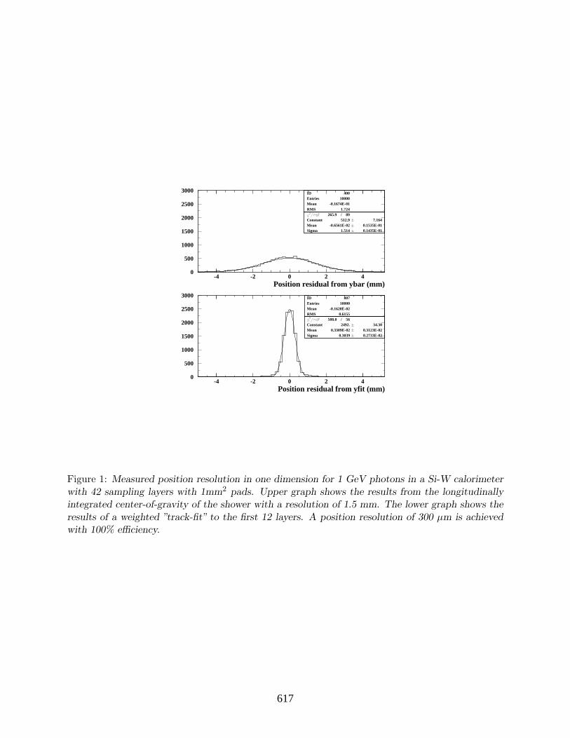
0
500
1000
1500
2000
2500
3000
-4 -2 0 2 4
IDEntriesMeanRMS
400 10000-0.1674E-01
1.724 265.9 / 89
Constant 512.9 7.164Mean -0.6561E-02 0.1535E-01Sigma 1.514 0.1435E-01
Position residual from ybar (mm)
IDEntriesMeanRMS
807 10000-0.1620E-02
0.6155 508.0 / 56
Constant 2492. 34.30Mean 0.3309E-02 0.3123E-02Sigma 0.3039 0.2733E-02
Position residual from yfit (mm)
0
500
1000
1500
2000
2500
3000
-4 -2 0 2 4
Figure 1: Measured position resolution in one dimension for 1 GeV photons in a Si-W calorimeterwith 42 sampling layers with 1mm2 pads. Upper graph shows the results from the longitudinallyintegrated center-of-gravity of the shower with a resolution of 1.5 mm. The lower graph shows theresults of a weighted ”track-fit” to the first 12 layers. A position resolution of 300 µm is achievedwith 100% efficiency.
297617

• EM-TAILCAL: About 15 radiation lengths of cheaper technology ECAL still with sam-pling frequency of at least every radiation length. The absorber could be Tungsten orLead. Lead would have the advantage of a better radiation length to interaction lengthratio, and being cheaper. Longitudinal compactness requirements would be less severe.This portion should also provide functionality at least as good as the chosen HCALtechnology, but needs to be analog.
This kind of arrangement is probably better suited to detector integration than the hybriddesigns we have been exploring. Each potentially different technology has its own radial space.However, the radial subdivision may also entail new difficulties with calibration and patternrecognition which would need to be investigated/minimized.
Broader Impact
The project will support participation of undergraduates in research.
Our on-going work with setting up cosmic-ray test facilities will be done in such a way thatwe can use the apparatus as part of an open-day type demonstration in conjunction with adiffusion cloud-chamber we recently acquired. This apparatus will allow the general public tosee and hear cosmic-ray muons.
We are interested in making movies which depict what happens in an e+e− interaction as thereaction products propagate through the detector and interact. The idea will be to captureimages of a simulated event at appropriate time intervals after the interaction. Particularlyrelevant to this project, is to depict well the electromagnetic shower development.
Results of Prior Research
[Progress to Date]
We have made progress on a number of issues related to this proposed project.
• We have studied the dependence of jet energy resolution on the intrinsic resolution ofthe tracker, the ECAL and the HCAL for all jet flavors. This study was carried outby Darius Gallagher (graduate student) under the supervision of Wilson. Results werereported at the Cornell, Summer 2003 meeting.
• Studies related to the importance of hermeticity in the detector design were describedin the TESLA TDR by Wilson [6], and related results were reported in a plenary talk atthe SLAC January 2004 ALCPG meeting [8]. Gallagher has been exploring the abilityto detect smuons in low visible energy scenarios where hermetic forward coverage isessential and the beam-hole caused by a large crossing-angle may be a hard limitation.
• Undergraduate student, Eric Benavidez, has been instrumental in developing our GEANT4capabilities under the supervision of Wilson. We have developed simulations related tothe following:
optical tracking of photons in scintillator tiles
simple sampling calorimeter test-beam geometries with arbitrary sampling media
pixelised sampling calorimeters
• We have used these simulation tools to study several issues relevant to the ECAL de-sign concept. These have been reported at the regular meetings both nationally andinternationally [9]. Some of the main results are the following:
298618

Characterization of the energy resolution dependence on absorber and active mate-rial thicknesses. Studies have been done for Si-W, Scint-W and hybrids with W absorberand both Si and scintillator active layers. In particular we demonstrated that thickerSilicon layers which lead to a higher sampling fraction benefit the energy resolution.Examples are shown in Figure 2 and Figure 3.
We have investigated the position resolution for photons as a function of the cellsize. We have found, (as we expected), that cell sizes much smaller than the Moliereradius, do indeed lead to much better position resolution. Even with 1mm pads, we stillfound a resolution of pad-size/
√
12.
Study of the correlation between the Silicon and scintillator response in hybrid struc-tures. An anti-correlation of as much as 20% was observed which goes in the directionof improving the energy resolution compared to that which would be obtained with pureSi-W or pure Scint.-W. This observation offers the possibility that novel media may leadto larger (and more beneficial) anti-correlations.
Study of some of the dynamic range issues associated with measuring beam energyelectrons and photons at the highest center-of-mass energies.
Observation that studies reported by other groups were using cutoffs in the electro-magnetic simulation which were affecting quantitatively their conclusions.
• We have developed a VME data acquisition system with multi-channel QDC’s and TDC’sfor measurements with scintillator-based detectors. Undergraduates Eric Benavidez andJonathan van Eenwyk have worked together with Wilson on the commissioning of thissystem. We have been using this with a cosmic-ray trigger, as a set-up designed fortesting scintillator-tile assemblies. We are currently getting this running with scintillatortiles from OPAL described in [12]. We also have some sources which will be used in thisstudy.
• We have been in communication with a number of potential collaborators, whom we areinterested in collaborating with on this or related projects.
M. Ronan, (LBL) : large detector concept
R. Frey, D. Strom (Oregon) : Si-W
J.C. Brient, (Ecole Polytechnique) : Si-W ECAL
M. Thomson, D.R. Ward, (Cambridge), calorimeter reconstruction
K. Kawagoe (Kobe), T. Takeshita (Shinshu), scintillating-tile ECAL
B. Dolgoshein (MePHI), M. Danilov (ITEP), Silicon-PM
V. Korbel, F. Sefkow (DESY), tile-HCAL applied to ECAL
V. Zutshi (NIU)
S. Kuhlmann, S Magill (Argonne)
P. Checchia (Padova)
D. Onoprienko, E. von Toerne, T. Bolton (Kansas State)
P. Baringer, A. Bean, D. Besson (Kansas)
N. Graf, A. Johnson (SLAC)
[Results of Grant most closely related to our LC research]
The grant most closely related to our LC research was the $7500 (including overhead) con-tribution we received from the UCLC planning grant in FY2003. The award period was July
299619
Active material thickness (mm)
Ene
rgy
reso
luti
on a
t 1
GeV
(pe
r ce
nt)
0
2.5
5
7.5
10
12.5
15
17.5
20
22.5
25
0 0.5 1 1.5 2 2.5 3 3.5 4 4.5 5
Figure 2: Dependence of energy resolution for 1 GeV photons on sampling layer thickness for 3different ECAL configurations. Each ECAL has 30 radiation lengths of Tungsten absorber (ie. 105mm of W).
300620

Photo-electron statistics ..
Scintillator plate thickness (mm)
Ene
rgy
reso
luti
on (
per
cent
)
8
9
10
11
12
13
14
15
0.5 0.75 1 1.25 1.5 1.75 2 2.25 2.5 2.75 3
Figure 3: Energy resolution for 1 GeV photons vs scintillator sampling thickness for 75 samplinglayer W calorimeters with 30 radiation lengths of W. The lowest curve shows the contribution fromonly sampling fluctuations. The four upper curves include the effect of photo-electron statistics withassumptions of 2.5 photo-electrons/mip/mm (upper curve), 5.0 pe/mip/mm, 10.0 pe/mip/mm and20.0 pe/mip/mm. Note the suppressed zero.
2003 to September 2004. This was targeted at our proposal entitled “Investigation and De-sign Optimization of a Compact Sampling Electro-magnetic Calorimeter with High Spatial,Timing and Energy Resolution”.
The funds were used to partially fund our undergraduate researchers, Benavidez and vanEenwyk. They were also used substantially for travel to workshops at which results werepresented and opportunities to discuss with colleagues and future collaborators presentedthemselves.
Results related to this grant are described above, and in more detail on the following webpage and related links [10].
This proposal is not for renewed support, but it does differ a little in scope compared tothe previous proposal to UCLC, in that now that the accelerator technology choice has beenmade, and a short bunch crossing time has been excluded, we have de-emphasized timingresolution.
Facilities, Equipment and Other Resources
Machine shop with two experienced machinists. CAD technician. Electronics engineer andelectronics technician. Instrumentation Design Lab. Linux cluster with 7 high-end dual-CPUmachines. Clean rooms with facilities designed for Silicon detectors. Cosmic-ray test-standwith VME data acquisition. Variety of check sources particularly ones with internal conversionelectrons.
FY2005 Project Activities and Deliverables
301621
We will investigate the performance characteristics of various ECAL concepts.
We will work on the photon reconstruction package for the particle flow algorithm. CarstenHensel (post-doc) will take the lead on this in collaboration with Norman Graf (SLAC). Thisactivity should be beneficial to all ECAL concepts and detector design concepts. Deliverableswill include characterization of the photon reconstruction performance. We are very keento also investigate the quality of reconstruction of photons inside hadronic jets (ie. nearinteracting charged particles). A useful figure of merit, which factorizes out neutral hadroneffects, may be the reconstructed visible energy in hadronic Z decays where there are noneutral hadronically interacting particles, nor neutrinos.
Depending on the realism achieved in the detector design simulation, we would also planon characterizing the expected photon response over the full solid angle paying particularattention to the regions where hermeticity might be compromised.
We are very interested in getting involved in test-beam tests of particularly photon/charged-hadron separation, and anticipate getting involved in current Si-W projects.
Investigation of Silicon-photomultipliers.
FY2006 and FY 2007 Project Activities and Deliverables
This proposal is targeted at the development of an electromagnetic calorimeter design conceptin calendar year 2005. We foresee future funding requests for the validation of design choicesand construction and testing of a prototype once we have converged on an electromagneticcalorimeter design concept.
Budget justification: University of Kansas
The budget and scope we have outlined for this project is primarily for the design of aconcept. In this respect a majority of the costs are associated with personnel (in the form ofundergraduate research support), and the support for travel. The travel will be associatedboth with software development, particularly in collaboration with SLAC, and also workrelated to the detector design concept which will involve travel to discuss with collaboratorsboth in Europe and Asia, and participation at the Snowmass workshop.
The materials and supplies items are associated with fabrication of scintillating-tile assembliesand associated photo-detectors.
Three-year budget, in then-year K$
Institution: University of Kansas
302622
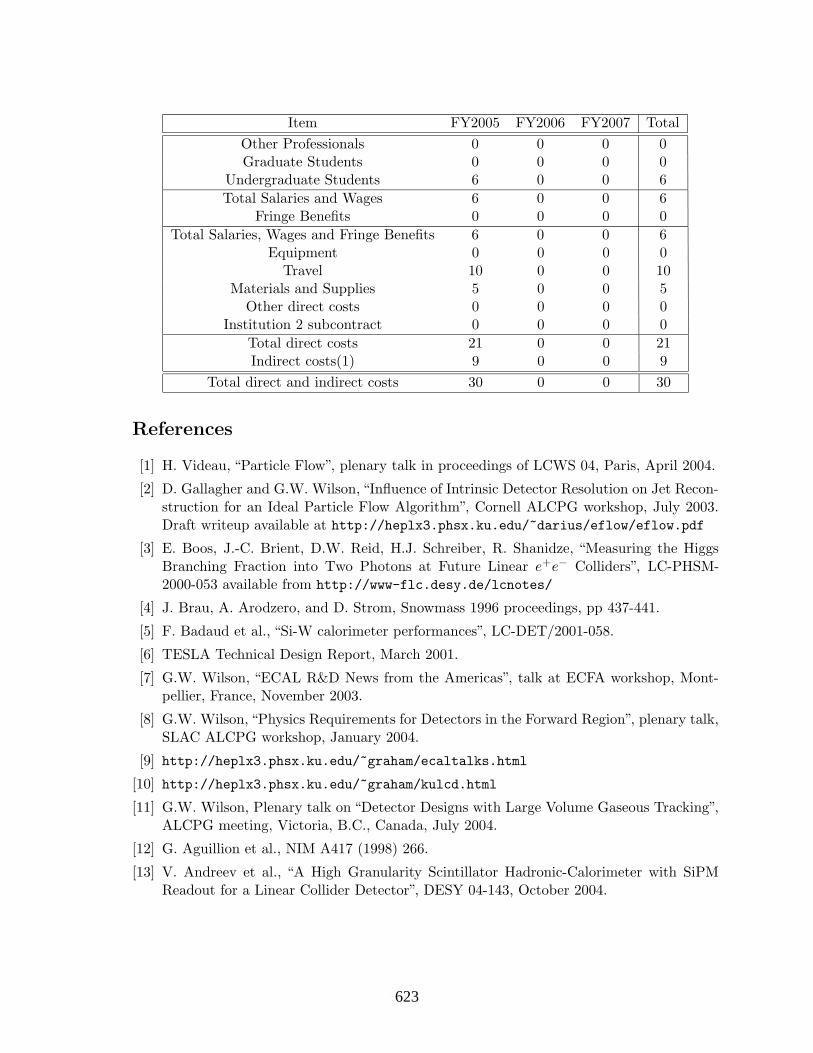
Item FY2005 FY2006 FY2007 Total
Other Professionals 0 0 0 0Graduate Students 0 0 0 0
Undergraduate Students 6 0 0 6
Total Salaries and Wages 6 0 0 6Fringe Benefits 0 0 0 0
Total Salaries, Wages and Fringe Benefits 6 0 0 6Equipment 0 0 0 0
Travel 10 0 0 10Materials and Supplies 5 0 0 5
Other direct costs 0 0 0 0Institution 2 subcontract 0 0 0 0
Total direct costs 21 0 0 21Indirect costs(1) 9 0 0 9
Total direct and indirect costs 30 0 0 30
References
[1] H. Videau, “Particle Flow”, plenary talk in proceedings of LCWS 04, Paris, April 2004.
[2] D. Gallagher and G.W. Wilson, “Influence of Intrinsic Detector Resolution on Jet Recon-struction for an Ideal Particle Flow Algorithm”, Cornell ALCPG workshop, July 2003.Draft writeup available at http://heplx3.phsx.ku.edu/~darius/eflow/eflow.pdf
[3] E. Boos, J.-C. Brient, D.W. Reid, H.J. Schreiber, R. Shanidze, “Measuring the HiggsBranching Fraction into Two Photons at Future Linear e+e− Colliders”, LC-PHSM-2000-053 available from http://www-flc.desy.de/lcnotes/
[4] J. Brau, A. Arodzero, and D. Strom, Snowmass 1996 proceedings, pp 437-441.
[5] F. Badaud et al., “Si-W calorimeter performances”, LC-DET/2001-058.
[6] TESLA Technical Design Report, March 2001.
[7] G.W. Wilson, “ECAL R&D News from the Americas”, talk at ECFA workshop, Mont-pellier, France, November 2003.
[8] G.W. Wilson, “Physics Requirements for Detectors in the Forward Region”, plenary talk,SLAC ALCPG workshop, January 2004.
[9] http://heplx3.phsx.ku.edu/~graham/ecaltalks.html
[10] http://heplx3.phsx.ku.edu/~graham/kulcd.html
[11] G.W. Wilson, Plenary talk on “Detector Designs with Large Volume Gaseous Tracking”,ALCPG meeting, Victoria, B.C., Canada, July 2004.
[12] G. Aguillion et al., NIM A417 (1998) 266.
[13] V. Andreev et al., “A High Granularity Scintillator Hadronic-Calorimeter with SiPMReadout for a Linear Collider Detector”, DESY 04-143, October 2004.
303623

6.14
6.14
Calorimetry
6.14: Construction of a Prototype Hadronic Calorimeter with Digital Readout
(new proposal)
Calorimetry
Contact person José Repond
[email protected] (630) 252-7554
Institution(s)
ANL Boston University
Chicago Fermilab
Iowa
New funds requested FY05 request: 105,000 FY06 request: 130,000 FY07 request: 55,000
304624

Construction of a Prototype Hadronic Calorimeter with Digital Readout
(LCRD)
Calorimetry
Contact person: José Repond e-mail: [email protected]
phone: (630)-252-7554
Argonne National Laboratory Boston University
University of Chicago Fermi National Accelerator Laboratory
University of Iowa
FY 2005: $105,000
305625

Project name Construction of a Prototype Section of a Digital Hadron Calorimeter Classification (accelerator/detector:subsystem) Detector Institution(s) and personnel Argonne National Laboratory: Gary Drake (electronics engineer), Steve Kuhlmann (staff scientist), Steve Magill (staff scientist), Brian Musgrave (scientist emeritus), José Repond (staff scientist), Dave Underwood (staff scientist), Barry Wicklund (staff scientist), Lei Xia (postdoctoral research associate) Boston University: John Butler (professor), Meenakshi Narain (professor) University of Chicago: Mark Oreglia (professor) Fermilab: James Hoff (electronics engineer), Abderrezak Mekkaoui (electronics engineer), Ray Yarema (electronics engineer) University of Iowa: Edwin Norbeck (professor), Yasar Onel (professor) Contact person José Repond [email protected] (630)-252-7554 Project overview We propose to construct a 1 m3 prototype section of a digital hadron calorimeter. The section will consist of 40 steel plates, each 20 mm thick, interleaved with Resistive Plate Chambers (RPCs) as the active medium. The segmentation of the readout will be extremely fine, 1 cm2 laterally and layer-by-layer longitudinally. The electronic readout will be reduced to a single bit per readout channel. This novel idea of a so-called digital hadron calorimeter (DHCAL) will be tested thoroughly in test beams at Fermilab. The tests will be either in stand-alone mode or together with a prototype of the
306626

electromagnetic calorimeter placed in front of the DHCAL. The proposed technology of a digital hadron calorimeter with RPCs is equally applicable to all three International Linear Collider detector design efforts, namely the SiD, the Large, and the Huge detectors. The purpose of constructing a prototype section and subsequent tests in particle beams are:
- Test of a calorimeter with RPCs: even though RPCs have been employed in a large number of HEP experiments, to date no calorimeter with RPCs as active medium has been built and tested. Our tests will validate the use of RPCs in calorimetry.
- Tests of the novel idea of a DHCAL: in simulation studies of a DHCAL the resolution obtained for hadrons is comparable to the results obtained with analog readout. Experimental verification of this and validation of the concept of a DHCAL is needed.
- Study of design parameters: measurements with different configurations of the prototype section will provide a better understanding of the dependence of the response to the various design parameters, such as the choice of absorber, the size of the active gap, the segmentation of the readout, etc.
- Measurement of hadronic showers: traditional calorimeters measure energy with a coarse segmentation, thus integrating over large volumes. Our DHCAL prototype section will measure hadronic showers with unprecedented spatial resolution, thus providing very detailed information on hadronic showers.
- Validation of Monte Carlo simulation of hadronic showers: the measurements obtained in a particle beam will be essential to validate the Monte Carlo simulation of hadronic showers. To date differences of up to 60% are observed when comparing the results on shower shapes based on different MC models of the hadronic shower. The design of a detector for the International Linear Collider is driven by the application of Particle Flow Algorithms for the measurement of hadronic jets. A realistic simulation of hadronic showers is a prerequisite for the development of a reliable design of such a detector.
- Comparison with an Analog Hadron Calorimeter: Currently the CALICE collaboration is assembling a prototype section of a hadron calorimeter using scintillator tiles and analog readout. The lateral size of the tiles is about a factor of 10 larger than the readout pads of the DHCAL.
The present proposal is a follow-up on last year’s proposal. The current overall status of the project is briefly summarized here:
- R&D concerning the RPCs is essentially complete. A design to be used for the prototype section has been developed.
- A concept for the electronic readout system has been proposed. The cost of the readout is approximately $1.4/readout channel.
- The front-end of the electronic readout is based on a custom ASIC. The design of the ASIC, contributed by Fermilab, is nearly complete.
307627
- The mechanical structure, consisting of a movable table and the absorber plates, has been designed and is currently being assembled at DESY.
- A detailed document outlining the special needs for test beams has been submitted to the Fermilab directorate.
Achievements in previous years Our project was initiated in 2002. In the following we shall briefly highlight the major achievements since then:
1) We have constructed ten chambers using as resistive plates glass of 0.85 and 1.10 mm thickness. The chambers feature either one or two gas gaps and have resistive paint layers with surface resistivity varying between ~100 kΩ and ~50 MΩ. The designs of the chambers vary significantly, with some chambers featuring only one glass plate, others having only one or no resistive layers. The active area of the chambers is approximately 20x20 cm2. A larger chamber with an area of 30 x 90 cm2 has also been built.
2) The electronic signal induced on the pick-up pad(s) has been characterized with respect to its timing characteristics and charge using a high resolution digital oscilloscope.
3) A cosmic ray test stand was built. 4) The chambers were tested extensively with a single readout pad of 17 x 17 cm2.
The signals were measured with an ADC and also shaped, amplified, discriminated and counted. The chambers were found to be very quiet (the noise rate is about 50 Hz) and highly efficient (>95%) in both avalanche and streamer mode.
5) The chambers were tested using different gas mixtures. For each mixture the overall efficiency and the fraction of streamers was determined as a function of applied high voltage. A default mixture for running in avalanche mode was established.
6) The efficiency as a function of position on the chamber was measured at the University of Chicago. As expected, the efficiency showed a dip at the location of the spacers holding the glass plates apart. The loss of efficiency is consistent with being limited to the area of the spacers.
7) A high voltage system based on the Cockcroft-Walton technology has been developed. First prototypes of the HV system have been tested with our prototype chambers and they performed satisfactorily.
8) The mechanical properties of the glass were measured to establish the bending due to gas pressure and the electric force.
9) A VME based multi-channel readout system has been designed, fabricated and assembled. The software for the data acquisition has been written and the system has been commissioned to take either triggered cosmic ray data or untriggered events for noise measurements.
10) The chambers were read out with 64 pads, each of 1 cm2. The signals were analyzed with an ADC system. The lateral distribution of the induced charge around the pad hit was measured.
308628

11) The hit multiplicity as a function of particle detection efficiency (adjustment of the discriminator threshold) was measured for several chambers based on different designs and as a function of applied HV.
12) Lower limits on the rate capability of the chambers were measured as a function of applied high voltage using a radioactive source, providing the rate, together with cosmic rays for the efficiency measurement.
13) A conceptual design of the readout system for a 1 m3 prototype section has been developed. The system is based on a front-end ASIC and contains a data concentrator, a data collector, and a timing and trigger system. Preliminary costs for the various subsystems of the electronic readout have been estimated. The design accommodates both RPCs and Gas Electronic Multipliers (or GEMs) as active detectors. The latter are currently being investigated by the University of Texas at Arlington.
14) The design of the front-end ASIC has been specified in a detailed document. The engineering of the chip has been started and is being provided by Fermilab. The digital part of the chip is complete.
15) The response of the 1 m3 prototype to single particles of various energies has been simulated using the GEANT4 package. Comparison of the response to electrons and pions using scintillator or RPCs as active medium showed that both electromagnetic and hadronic showers appear narrower when using RPCs. The reasons for this different behavior have been established. The narrower showers constitute a clear advantage for the application of Particle Flow Algorithms.
16) In collaboration with other institutions developing calorimeter prototypes for the ILC, a technical note detailing the needs for test beams has been drafted and submitted to Fermilab.
17) Progress with our R&D activities has been presented at meetings of the Linear Collider community and also at conferences dedicated to detector developments.
18) A digital hadron calorimeter with RPCs as active medium has been chosen as the default option for the SiD detector design effort.
Description of project activities in the following years For FY2005 we plan the following activities:
1) We will construct additional large chambers with dimensions matched to the planned prototype section.
2) We will test the performance of these chambers, in particular the uniformity of the response.
3) We will develop a design for the 1 m3 prototype section and start constructing the first chambers.
4) We will design and prototype the front-end boards containing the readout pad and the front-end ASIC.
5) We will complete the design of the ASIC and submit the design for a prototype run.
309629

6) We will measure the performance of the prototype ASIC in great detail using specially designed test fixtures.
7) We will design and prototype the data concentrator boards. 8) We will design and prototype the VME based data collector system. 9) We will design and prototype the timing and trigger system. 10) We will design and prototype the high voltage distribution system 11) We will develop a gas distribution system.
For FY2006 we plan the following activities. These activities will in part be supported by a separate MRI proposal submitted to the NSF. The dollar amounts are quoted excluding contingencies:
1) We will build the RPCs for the prototype section. We foresee building 120 chambers plus of the order of 10 spares.
2) We will build the electronic readout system for the prototype section including the front-end ASICs ($225k), the front-end readout boards ($50k), the data concentrator boards containing FPGAs($85k), and 40 VME cards ($60k) for data collection.
3) We will purchase low voltage power supplies ($50k), optical fibers and other transmission cables ($5k) and 2 VME crates with power supplies ($15k
4) We will build or purchase the High Voltage and gas distribution systems. The following activities are planned for FY2007:
1) Transportation of the chambers to the Fermilab test beam. 2) Assembly of the prototype section. 3) Testing with particle beams. 4) Detailed Monte Carlo simulation of the response of the prototype section to single
particles.
310630

Responsibilities as currently assigned Argonne National Laboratory Construction of chambers
Overall electronic system design Test fixtures for front-end ASIC VME based data collector system Transportation of RPCs to test beam
Boston VME based data collector system Chicago Data concentrator boards FNAL Front-end ASICs
Front-end readout boards Iowa High voltage distribution system
Gas distribution system UTA* Timing and triggering system Washington* Data acquisition and VME programming
* not part of this proposal Engineering and technical effort during FY2005 Engineering and technical support will be needed for the following tasks:
1. The design and construction of chambers for the prototype section. 2. The design and prototyping of the readout system for the prototype section,
including the development of the front-end ASIC (provided by Fermilab), the design of the front-end board (located on the RPCs), the data concentrators and the data collector systems.
3. The design and fabrication of test fixtures for the prototype ASICs. Current and Pending Support The following concerns the Argonne Linear Collider Detector R&D group only. The funds are being used to support one postdoctoral research assistant, the design efforts (engineers) and the prototyping of parts of the electronic readout system. Current Project: Precision Measurements of Hadronic Showers Funding agency: Argonne National Laboratory Program: Laboratory Directed Research and Development (LDRD) Status: Awarded Duration: One year Amount: $181,500
311631
The following concerns the Argonne Linear Collider Detector R&D group only. The funds are being requested for the front-end electronics of the prototype section. The proposal is being submitted jointly with the University of Oregon and the University of Texas at Arlington. Pending Project: Development of Calorimeter Prototype Modules for
International Linear Collider Test Beam Program Funding agency: NSF Program: MRI Status: to be submitted Duration: 3 years Amount: $950,000 Broader Impact The challenges raised by the linear collider physics program promote the development of new detector technologies. The necessary fine granularity of the hadron calorimeter requires a novel technical approach. The proposed digital hadron calorimeter with Resistive Plate Chambers as active medium fulfills the physics criteria, but has never been built and tested before. These technological challenges require close collaboration between industries, universities and national laboratories. The project involves a number of graduate and undergraduate students associated with the universities participating in this proposal. At Argonne the project will attract participation from high school teachers and summer students. The detailed measurements of the response to single particles will further the understanding of hadronic showers and provide a unique data base for comparison with simulation. The results from this program will be disseminated through national and international conferences and workshops and published in peer-reviewed journals. Facilities, Equipment and other Resources All institutions included in this proposal have outstanding electronic engineering capabilities and electronic design facilities. Mechanical work will be mostly done at Argonne. The latter has a mechanical shop with many years of experience in designing and constructing calorimeters for high energy physics experiments.
312632
Budget and budget justification Institution Item FY2005 FY2006 FY2007
Summer students, other professionals Engineering
Supported from
base funds M&S for (prototype) electronics
30,000 40,000
Argonne
Transportation of RPCs to testbeam
20,000
Students, other professionals
5,000 5,000 5,000
Engineering 5,000 5,000 5,000
Boston
M&S for (prototype) electronics
15,000 20,000
Engineering 5,000 5,000 5,000 Chicago M&S for (prototype) electronics
15,000 20,000
FNAL Engineering Funded elsewhere Students, other professionals
5,000 5,000 5,000
Engineering 5,000 5,000 5,000
Iowa
M&S for HV and gas system
15,000 20,000
All Travel 5,000 5,000 10,000 Total 105,000 130,000 55,000
313633

6.16
6.16
Calorimetry
6.16: Dual-Readout Calorimetry for the ILC
(new proposal)
Calorimetry
Contact person Richard Wigmans
[email protected] (806) 742-3779
Institution(s)
U.C. San Diego Iowa State Texas Tech
New funds requested FY05 request: 50,000
FY06 request: 120,000 FY07 request: 80,000
314634
Dual-Readout Calorimetry for the ILC
Classification (subsystem)
Calorimeter
Personnel and Institution(s) requesting funding
Texas Tech University: N. Akchurin, H. Kim and R. WigmansUniversity of California at San Diego: H.P. PaarIowa State University: J. Hauptman and J. Lamsa
Collaborators
A. Penzo (INFN Trieste, Italy)
Collaborating personnel will work on the project but are not requesting funding here.
Project Leader
Dr. Richard [email protected](806) 742-3779
Project Overview
The DREAM (Dual-REAdout Module) calorimeter was developed as a device that wouldmake it possible to perform high-precision measurements of hadrons and hadron jets, whilenot subject to the limitations imposed by the requirements for compensating calorimetry.The detector is based on a copper absorber structure, equipped with two types of activemedia which measure complementary characteristics of the shower development. Scintillatingfibers measure the total energy deposited by the shower particles, while Cerenkov light is onlyproduced by the charged, relativistic shower particles. Since the latter are almost exclusivelyfound in the electromagnetic (em) shower component (dominated by π0s produced in hadronicshowers), a comparison of the two signals makes it possible to measure the energy fractioncarried by this component, fem, event by event. As a result, the effects of fluctuations inthis component, which are responsible for all the traditional problems in non-compensatingcalorimeters (non-linearity, poor energy resolution, non-Gaussian response function), can beeliminated, and an important improvement in the hadronic performance is achieved.
The results of our work so far, details of which are given in the section “Results of PriorResearch” demonstrate that the complementary information from dE/dx and from the pro-duction of Cerenkov light in the same showers provides a very powerful tool for improvinghadronic calorimeter performance. In the proposed project, we would like to study how thisprinciple could be optimally applied in a practical 4π detector for an experiment at the ILC.We want to concentrate on two aspects:
1. The electromagnetic section
2. The readout
315635
The electromagnetic section
The benefits of the dual-readout method are by no means limited to fiber calorimeters. Anymedium that generates both Cerenkov light and scintillation light can be used for this purpose.And since the sampling fraction does not have to have a specific value (as in compensatingcalorimeters), there is no reason why a calorimeter based on the dual-readout principle couldnot have excellent electromagnetic energy resolution. An attractive and cost-effective optionwhich we would like to investigate is an electromagnetic section consisting of trapezoidallead-glass blocks doped with an appropriate scintillating agent. The concentration of thedopants and their properties (decay time, spectrum) should be chosen such as to optimizethe efficiency with which the scintillation and Cerenkov signals could be separated from eachother.
We foresee a three-year program for this part of the project, which will be concentrated atTexas Tech University. In Year 1, we will investigate different dopants and doping techniques.A number of small doped lead glass blocks will be produced and tested, with the electron Vande Graaff accelerator at Texas Tech University. In Year 2, we will build and assemble a fullelectromagnetic detector based on the chosen, optimized technique. In Year 3, this detectorwill be combined with the existing DREAM hadron calorimeter, and tested in high-energyparticle beams at CERN or Fermilab.
The readout
The fiber-based DREAM calorimeter could in principle form an excellent and cost-effectivesolution for the hadronic section of a calorimeter system for a Linear Collider experiment.However, the readout of its many fibers would present a substantial challenge. The scintil-lating fibers and the Cerenkov fibers have to be grouped in separate bunches for readout bytheir respective light detectors. The prototype that was extensively tested in particle beamswas read out with standard photomultipliers (PMTs), two per tower. The grouping of thefibers was labor intensive and required the fibers to extend about 50 cm beyond the end of thecalorimeter. While this worked very well in the beam tests, it probably would not scale wellwith the lateral size of the calorimeter. We propose R&D on a variety of readout techniquesto see if we can identify and develop a readout method that is practical and consistent withthe requirements of an actual ILC experiment.
To reduce the amount of work required for separating the fibers into bunches, it is clearlyadvantageous if the bunches can be made as small as possible and be directed to their re-spective readout elements without too much routing. At the present time, great advantagesin that respect seem to be offered by the use of silicon photomultipliers (SiPM).
These devices were developed a few years ago by a group from the Moscow Engineering andPhysics Institute, in collaboration with the ”Pulsar Enterprise” and the Lebedev PhysicalInstitute. They consist of many (approximately 1000 per mm2) Si pixels operating in alimited Geiger mode with a gain of 106. Each pixel is operated in a binary mode, but becauseof the high pixel density, each pixel sees on average less than one photon, so that the responseis linear. As the number of photons per mm2 increased, the pixels have to be made smaller tokeep the number of photons per pixel less than 1. The current state of the art is 2500 pixels permm2, adequate for our purposes. The signals from the pixels are readout by aluminum stripsconnected to the individual pixels to collect their summed signal. We want to investigateif these strips could be tailored to form readout patches each consisting of many pixels but
316636
small enough to accept scintillating or Cerenkov fibers on each patch. There is a trade-offto be made between the number and size of the patches on the one hand and the number offiber bunches to be made and routed on the other hand.
Published tests (B. Dolgoshein et al., Int. Conf. on New Developments in Photodetection,Beaune, France, June 2002) show that the SiPM have properties similar to the best PMTsin terms of gain, noise, time resolution, and single-photon detection (good for calibration)but they do not require high voltage (tens of Volts are sufficient), can operate in magneticfields, have better stability under temperature and voltage variations. Their dynamic range(∼ 1000) is more limited than for PMTs but adequate for our purposes.
Also for this part of the project, we foresee a three-year program. UCSD will be the leadinstitution for this part. In Year 1, we will investigate SiPM’s properties using light sources.Especially spatial uniformity of response, linearity, spectral respsonse, and stability undervoltage and temperature variations are of interest. In parallel and as a possible alternative,we will investigate standard multi-anode PMTs. In Year 2, we will build a small version ofthe DREAM calorimeter, using existing spare material from the existing project, and equipit with the readout chosen on the basis of the Year 1 R&D. In Year 3, this calorimeter willbe tested in high-energy particle beams at CERN or Fermilab.
Broader Impact
This proposal, if funded, will contribute to the knowledge base in our respective Physics De-partments. The beneficiaries of that will be postdocs, graduate students, and undergraduatestudents participating in the research funded in this proposal.
One of us (Hans P. Paar) is co-director of NSF’s REU (Research Experience for Undergradu-ates) program located in UCSD’s Physics Department. Through this program, we will recruitundergraduates, generally from disadvantaged backgrounds, to participate in our research pro-gram. This includes taking them with us to an accelerator laboratory such as FermiLab orCERN where they can experience first hand the atmosphere of forefront research.
As in the case of the DREAM project, we will involve TTU Quarknet treachers and theirhighschool students in construction, tests and analyses, where possible.
Faculty will recruit junior and senior undergraduates to participate in our laboratory basedresearch. There they will use the state-of-the-art equipment to which this Grant has con-tributed.
Undergraduates working in our labs will often present their research at an UndergraduateResearch Conference, attended by their peers and faculty supervisors. Here they learn whatit means to stand up and present your results and answer questions ”on your feet”.
Results of Prior Research
This project, known by its acronym DREAM (Dual-REAdout Module) was started in 2001,with a grant ($150K) received by the project leader in the context of the Advanced ResearchProgram of the State of Texas. In 2002, this grant was supplemented by funds from DOE’sAdvanced Detector Research program. Since then, the proponents have received a totalamount of $340K from the latter source, in four installments.
We have used these funds to construct and test a generic prototype, which was intended totest the dual-readout principles and measure the extent to which the performance of hadroncalorimeters could be improved by making use of these principles. The detector is based
317637

on a copper absorber structure, equipped with two types of active media which measurecomplementary characteristics of the shower development. Scintillating fibers measure thetotal energy deposited by the shower particles, while Cerenkov light is only produced by thecharged, relativistic shower particles. The total instrumented mass is 1030 kg (depth 10 λint),and the 36,000 fibers are read out by 38 PMT’s.
This detector was built in the Physics department of Texas Tech University and then shippedto CERN, where it was tested with high-energy pions, electrons and muons in the H4 beamof the Super Proton Synchrotron. CERN allocated three testbeam periods to this project,during the summers of 2003 and 2004.
The results of these tests are described in a number of papers. Three papers have alreadyappeared in the scientific literature:
• N. Akchurin et al., Muon Detection with a Dual-Readout Calorimeter,Nucl. Instr. and Meth. A533 (2004) 305–321.• N. Akchurin et al., Electron Detection with a Dual-Readout Calorimeter,
Nucl. Instr. and Meth. A536 (2005) 29–51.• N. Akchurin et al., Hadron and Jet Detection with a Dual-Readout Calorimeter,
Nucl. Instr. and Meth. A537 (2005) 537–561.
A fourth paper has been accepted for publication:
• N. Akchurin et al., Comparison of High-Energy Electromagnetic Shower Profiles Mea-sured with Scintillation and Cerenkov Light,Accepted for publication in Nucl. Instr. and Meth.
Two other papers are in an advanced state of preparation. The DREAM project was alsopresented in two talks at the XIth International Conference on Calorimetry in High EnergyPhysics (Perugia, Italy, 2004). In his summary talk, the speaker called DREAM the mostsignificant new development in calorimetry in recent history. All papers can also be found atthe website of the DREAM project: http://www.phys.ttu.edu/dream/
The idea to combine the complementary information from dE/dx and from the productionof Cerenkov light has been proven to be a very powerful tool for improving the hadroniccalorimeter performance (Figure 1). The performance of our detector is considerably superiorto what is commonly achieved with hadron calorimeters used in particle physics experiments.For example, high-energy (200 GeV) jets were measured with a resolution better than 4%(Figure 1b). Because of the limited size (the total instrumented mass of the test modulewas only 1030 kg), fluctuations in (lateral) shower leakage contributed significantly to themeasured resolution. We have shown that if we made use of the fact that the jet energywas known (thus effectively eliminating the contributions of shower leakage to the results),the mentioned resolution could be further improved by a factor of two (Figure 1c). Similarimprovements may thus be expected for a detector with a larger instrumented mass than thedevice tested in this study.
Perhaps even more important is the fact that the (simple) procedure we developed to correctevent by event for differences in the electromagnetic shower fraction automatically led to acorrect reconstruction of the shower energy, both for jets and for single hadrons, in an instru-ment calibrated with electrons, over the full energy range at which the detector was tested.Anyone who has ever worked with a hadron calorimeter in an experiment will appreciate thisvery important feature, which is illustrated in Figure 2.
318638

Figure 1: Scintillator signal distributions for 100 GeV π− in the DREAM calorimeter before any correctionswere made(a), after the corrections based on the observed Q/S signal ratio were applied (b) and after, inaddition, leakage fluctuations were eliminated (c). See text for details.
In the second stage of this project (DREAM-2) , which was separately reviewed, approvedand funded by DOE (2003), we investigated if and to what extent the signals from a mediumthat generates both scintillation and Cerenkov light can be split into these two components.For these studies, part of the DREAM calorimeter was modified. The fibers from a readoutcell were split into three bunches instead of the usual two. These bunches contained onlyscintillating fibers, only quartz fibers, or a mixture of the two types of fibers, respectively.Different techniques to separate the two types of light were being tried on this mixture, andthe quality of the separation could be verified event by event with the “pure” signals.
In order to distinguish between the two types of light, we investigated three different charac-teristics:
1. The time structure of the signals. Cerenkov light is instantaneous, while scintillation isa process with one or more typical time constants.
2. The directionality of the light. Scintillation light is emitted isotropically, while Cerenkovlight is emitted at a characteristic angle with the direction of the superluminous showerparticle that generates it.
3. The light polarization. Unlike scintillation light, Cerenkov light is polarized.
A fourth characteristic, the spectral distribution, was not investigated so far, because we didnot see an easily applicable method to exploit differences between the spectra of the two typesof light generated by this type of calorimeter.
319639

Figure 2: The calorimeter response (average signal per GeV) for single pions and high-multiplicity jets, asa function of energy, before and after corrections made on the basis of the measured Q/S signal ratio. Theresponse is normalized to electrons.
The difference in directionality was exploited by reading the fibers from both ends. Thepreliminary results are very encouraging. The ratio between the signals measured at bothends of the fiber was found to be more than a factor of 3 smaller for pure Cerenkov lightthan for pure scintillation light. By measuring this ratio for mixed signals, the compositionof the light in that mixture could be determined, event by event. Also the differences in timestructure made this possible, as illustrated in Figure 3. Not surprisingly, the measurement ofthe composition of a given signal was most precise when the relative numbers of scintillationand Cerenkov photons were compatible. At the present time, we are analyzing these andother data collected during the most recent beam tests and expect this to result in at leastone additional DREAM publication in the coming year.
Facilities, Equipment and Other Resources
The TTU HEP labs are equipped with generic NIM, CAMAC and VME electronics. Severalspecialized tools were designed and manufactured for fiber cleaving, polishing and terminationduring the DREAM project. Some funds for modification and upgrade of this equipment arerequested.
Our computer facilities are well-equipped for Monte Carlo calculations and data analyses withthe newest versions of the common simulation packages. For bench test measurements, wehave adequate data acquisitions systems and electronics as well.
We anticipate using different types of spectrometers for the analyses of light from a varietyof active media (scintillation and Cerenkov radiation). We may have to augment our exist-ing spectrometers with different gratings to gain enhanced sensitivity to various wavelengthregions.
The TTU HEP lab operates a 2-MeV electron Van de Graaff that we used extensively inthe early stages of fiber selection for the DREAM project. We anticipate using this versatileaccelerator in the initial phases of these studies.
320640

Figure 3: The relationship between the measured ratio of the Cerenkov and scintillator signals from 100GeV “jets”, and the percentage of the signal that was recorded in the tail, i.e. more than 12 ns after the start.Preliminary results.
It is important to note that this proposal builds on a recent successful R&D program (DREAM).This has several positive implications:
• The absorber, standard scintillating and Cerenkov (quartz and clear plastic) fibers, andphotomultipliers already exist.
• The proponents of this proposal have invested many years developing new calorimetertechniques and have been very effectively working as a single team.
• The two proposals (Dual-Readout Calorimetry for ILC and Ultimate Hadron Calorime-try) we submit in this context for consideration are tightly coupled in all kinds of re-sources.
All of the above provide a unique and proven synergy.
FY2005 Project Activities and Deliverables
In 2005, we plan to investigate different dopants and doping techniques. A small numberof doped lead glass blocks will be produced and tested, with the electron Van de Graaffaccelerator at TTU. We will also investigate relevant SiPM’s properties using light sources.Especially spatial uniformity of response, linearity, spectral respsonse, and stability undervoltage and temperature variations are of interest to this project. In parallel and as a possiblealternative, we will investigate standard multi-anode PMTs. Where possible, results fromthese two readout systems will be compared.
FY2006 Project Activities and Deliverables
We anticipate building a full size electromagnetic calorimeter based on the chosen and opti-mized doping technique. If this module is ready in time, high-energy beam tests may also be
321641

carried out. We will build a small version of the DREAM calorimeter and equip it with thereadout chosen on the basis of the Year 1 R&D.
FY2007 Project Activities and Deliverables
We plan a combined electromagnetic and hadronic prototype test at a high-energy particleaccelerator. A new fully sampling em calorimeter followed by the existing DREAM hadroncalorimeter, possibly equipped with three different types of fibers, will be exposed to beamsof electrons, hadrons and “jets”. The new small DREAM-like module, equipped with the newreadout, will also be tested, in electron beams.
Budget justification: Texas Tech University will be the lead institution in this project.We plan to use professional expert assistance in scintillator dopants and doping techniques(∼9K$). We plan to involve undergraduate students as the project develops. The fringebenefits rate is assumed to be 25% on salaries and the salary expenditure with fringe benefitsis ∼16K$.
Equipment, materials and supplies will dominate the cost of this project.
We assumed no overhead charge on equipment and travel. A similar agreement was reachedwith the TTU Office of Research Services for previous grants of this type. TTU will chargeoverhead on salaries at the off-campus rate (26.5%).
TTU will subcontract the University of California at San Diego and Iowa State University.Separate tables for these subcontracts are shown below.
Three-year budget, in then-year K$
Institution: Texas Tech University
Item FY2005 FY2006 FY2007 TotalOther Professionals 3.0 3.0 3.0 9.0Graduate Students 0 0 0 0
Undergraduate Students 0 2.0 2.0 4.0Total Salaries and Wages 3.0 5.0 5.0 13.0
Fringe Benefits 0.8 1.3 1.3 3.3Total Salaries, Wages and Fringe Benefits 3.8 6.3 6.3 16.3
Equipment 0 5.0 8.0 13.0Travel 5.0 10.0 10.0 25.0
Materials and Supplies 10.3 30.0 11.1 51.4Other direct costs 0 12.1 8.0 20.1
UC-San Diego subcontract 20.0 40.0 20.0 80.0Iowa State U subcontract 10.0 15.0 15.0 40.0
Total direct costs 49.1 118.3 78.3 245.7Indirect costs 1.0 1.7 1.7 4.3
Total direct and indirect costs 50.0 120.0 80.0 250.0
322642

Budget justification:
University of California at San Diego will concentrate on new readout techniques, particularlySiPMs. In Year 2, investment in electronics design is expected. Throughout this project, amodest expenditures are planned to purchase SiPMs and related hardware. Similarly, smallamount funds are forseen for travel for group meetings and beam tests.
Three-year budget, in then-year K$
Institution: University of California at San Diego
Item FY2005 FY2006 FY2007 TotalOther Professionals 0 18.5 0 18.5Graduate Students 0 0 0 0
Undergraduate Students 0 0 0 0Total Salaries and Wages 0 18.5 0 18.5
Fringe Benefits 0 3.1 0 3.1Total Salaries, Wages and Fringe Benefits 0 21.7 0 21.7
Equipment 7.4 3.0 6.0 16.4Travel 5.0 5.0 6.1 16.1
Materials and Supplies 5.0 2.7 5.0 12.7Other direct costs 0 0 0 0Total direct costs 17.4 32.4 17.1 66.9
Indirect costs 2.6 7.6 2.9 13.1Total direct and indirect costs 20.0 40.0 20.0 80.0
Budget justification:
Iowa State University has a long track record in detailed calorimeter simulations. JohnHauptman will partially fund a graduate student (3 months out of a year) for three years. Amodest amount of travel funds are required to travel to meetings and beam tests.
Three-year budget, in then-year K$
Institution: Iowa State University
Item FY2005 FY2006 FY2007 TotalOther Professionals 0 0 0 0Graduate Students 5.0 5.0 5.0 15.0
Undergraduate Students 0 0 0 0Total Salaries and Wages 5.0 5.0 5.0 15.0
Fringe Benefits 1.3 1.3 1.3 3.8Total Salaries, Wages and Fringe Benefits 6.3 6.3 6.3 18.8
Equipment 0 0 0 0Travel 2.1 7.1 7.1 16.3
Materials and Supplies 0 0 0 0Other direct costs 0 0 0 0Total direct costs 8.3 13.3 13.3 35.0
Indirect costs 1.7 1.7 1.7 5.0Total direct and indirect costs 10.0 15.0 15.0 40.0
323643
6.17
6.17
Calorimetry
6.17: Ultimate Hadron Calorimetry
(new proposal)
Calorimetry
Contact person Richard Wigmans
[email protected] (806) 742-3779
Institution(s)
U.C. San Diego Iowa State Texas Tech
New funds requested FY05 request: 50,000 FY06 request: 50,000 FY07 request: 30,000
324644

Ultimate Hadron Calorimetry
Classification (subsystem)
Calorimeter
Personnel and Institution(s) requesting funding
Texas Tech University: N. Akchurin, H. Kim and R. Wigmans
Collaborators
University of California at San Diego: H.P. PaarIowa State University: J. Hauptman and J. LamsaA. Penzo (INFN Trieste, Italy)
Collaborating personnel will work on the project but are not requesting funding here.
Project Leader
Dr. Richard [email protected](806) 742-3779
Project Overview
High-precision measurement of the 4-vectors of hadrons and jets is an essential requirementfor experiments at the ILC, and one of the main goals in developing a detector for such anexperiment.
Thirty years of experience have taught us that hadron calorimetry is extremely non-trivial.Unfortunately, Monte Carlo simulations of the type available in the GEANT package havelittle predictive value for the performance of hadron calorimeters. Progress in our under-standing of hadron calorimetry has been entirely due to generic detector R&D projects of thetype proposed here.
In most hadron calorimeters, the performance is dominated (and spoiled) by the fact thatthe response to the electromagnetic (em) shower component is different from that to thenon-em shower component: e/h = 1. Fluctuations in the energy fraction carried by the emcomponent (fem), dominate the energy resolution and the (non-Gaussian) lineshape, whilethe energy dependence of the average value of fem causes (a usually substantial) non-linearity.
There are two proven ways to eliminate these problems and improve the calorimeter perfor-mance.
1. Make the calorimeter compensating (e/h = 1)
2. Measure the value of fem event by event and correct for the response differences men-tioned above.
The compensation mechanism is now well understood. It can be achieved by designing thecalorimeter in such a way that the signals from neutrons, abundantly produced in the non-emshower component, are boosted to such an extent that they, on average, compensate for the“invisible” energy resulting from nuclear breakup. In practice, this can be achieved with asampling calorimeter with a hydrogenous active medium. The sampling fraction has to besmall, e.g. 2.4% in lead/plastic-scintillator structures, ∼ 10% in uranium/plastic-scintillator.
325645

Such calorimeters work very well, and they hold all world records for hadronic performance.However, they have a few disadvantages. Because of the crucial contribution of neutrons,one has to integrate the signals over a large detector volume (1 m3) and a considerabletime (100 ns) to achieve this performance. Also, because of the small sampling fraction,the resolution for em shower detection is limited. The best em resolutions reported forcompensating calorimeters are ∼ 10%/
√E.
The DREAM (Dual-REAdout Module) calorimeter was developed as a device that wouldmake it possible to perform high-precision measurements of hadrons and jets, while not subjectto these limitations. It is based on the second principle mentioned above, measuring fem eventby event. The detector is based on a copper absorber structure, equipped with two typesof active media which measure complementary characteristics of the shower development.Scintillating fibers measure the total energy deposited by the shower particles, while Cerenkovlight is only produced by the charged relativistic shower particles. Since the latter are almostexclusively found in the electromagnetic shower component (dominated by π0s produced inhadronic showers), a comparison of the two signals makes it possible to measure the energyfraction carried by this component event by event.
The idea to combine the complementary information from dE/dx and from the productionof Cerenkov light has been proven to be a very powerful tool for improving the hadroniccalorimeter performance (see the section “Results of Prior Research” for details). Based onthe successes achieved so far, we believe that we can take this approach one step further, inan attempt to obtain the ultimate hadron calorimeter.
The ultimate limitation on the resolution that can be achieved with a hadron calorimeteris determined by fluctuations in (in-)visible energy, i.e. fluctuations in the energy fractionthat is used to break up atomic nuclei and thus does not contribute to the measured signals.Fortunately, this fraction is correlated to the total kinetic energy of the neutrons liberatedin this process, especially in high-Z absorber materials such as lead. Therefore, efficientdetection of these neutrons is key to obtaining the best possible energy resolution.
We propose to modify the existing DREAM calorimeter in such a way that a separate mea-surement of the kinetic energy carried by shower neutrons, E(n), becomes possible. Webelieve that the combined information from dE/dx, Cerenkov light and E(n) will maximizethe relevant knowledge about the developing showers and, therefore, will provide the ultimatehadron calorimetry. We propose two avenues to achieve this goal:
1. Replace every second plastic scintillating fiber by a non-hydrogenous scintillating fiber,e.g. quartz doped with a scintillating agent. A comparison of the signals from thesetwo types of fibers will provide E(n), since the only difference between these two signalscomes from the neutrons.
2. Replace one or several fibers in each copper tube with fibers that are made specificallysensitive to MeV-type neutrons, e.g. using boron.
The first method will almost certainly work, but since quartz fibers are very expensive, thesecond method has a better potential to provide a cost-effective solution. That’s why we wantto investigate both options.
In Year 1, we want to dedicate ourselves to the purely generic part of this project, i.e. in-vestigate the advantages and disadvantages of all different options. In Year 2, we want toimplement the chosen solution in our DREAM calorimeter and perform high-energy beam
326646

tests at CERN or Fermilab. We realize that the existing prototype detector (1030 kg) is toosmall to achieve the ultimate performance allowed by this triple-readout approach. However,we expect that the improvement of the performance compared to the dual-readout versionwill allow us to fully assess the possibilities of this new technique.
Broader Impact
This proposal, if funded, will contribute to the knowledge base in our respective Physics De-partments. The beneficiaries of that will be postdocs, graduate students, and undergraduatestudents participating in the research funded in this proposal.
One of our collaborators (Hans P. Paar) is co-director of NSF’s REU (Research Experience forUndergraduates) program located in UCSD’s Physics Department. Through this program,we will recruit undergraduates, generally from disadvantaged backgrounds, to participate inour research program. This includes taking them with us to an accelerator laboratory such asFermiLab or CERN where they can experience first hand the atmosphere of forefront research.
As in the case of the DREAM project, we will involve TTU Quarknet treachers and theirhighschool students in construction, tests and analyses, where possible.
Faculty will recruit junior and senior undergraduates to participate in our laboratory basedresearch. There they will use the state-of-the-art equipment to which this Grant has con-tributed.
Undergraduates working in our labs will often present their research at an UndergraduateResearch Conference, attended by their peers and faculty supervisors. Here they learn whatit means to stand up and present your results and answer questions ”on your feet”.
Results of Prior Research
The DREAM project was started in 2001, with a grant ($150K) received by the projectleader in the context of the Advanced Research Program of the State of Texas. In 2002, thisgrant was supplemented by funds from DOE’s Advanced Detector Research program. Sincethen, the proponents have received a total amount of $340K from the latter source, in fourinstallments.
We have used these funds to construct and test a generic prototype, which was intended totest the dual-readout principles and measure the extent to which the performance of hadroncalorimeters could be improved by making use of these principles. The detector is basedon a copper absorber structure, equipped with two types of active media which measurecomplementary characteristics of the shower development. Scintillating fibers measure thetotal energy deposited by the shower particles, while Cerenkov light is only produced by thecharged, relativistic shower particles. The total instrumented mass is 1030 kg (depth 10 λint),and the 36,000 fibers are read out by 38 PMT’s.
This detector was built in the Physics department of Texas Tech University and then shippedto CERN, where it was tested with high-energy pions, electrons and muons in the H4 beamof the Super Proton Synchrotron. CERN allocated three testbeam periods to this project,during the summers of 2003 and 2004.
The results of these tests are described in a number of papers. Three papers have alreadyappeared in the scientific literature:
• N. Akchurin et al., Muon Detection with a Dual-Readout Calorimeter,Nucl. Instr. and Meth. A533 (2004) 305–321.
327647

• N. Akchurin et al., Electron Detection with a Dual-Readout Calorimeter,Nucl. Instr. and Meth. A536 (2005) 29–51.
• N. Akchurin et al., Hadron and Jet Detection with a Dual-Readout Calorimeter,Nucl. Instr. and Meth. A537 (2005) 537–561.
A fourth paper has been accepted for publication:
• N. Akchurin et al., Comparison of High-Energy Electromagnetic Shower Profiles Mea-sured with Scintillation and Cerenkov Light,Accepted for publication in Nucl. Instr. and Meth.
Two other papers are in an advanced state of preparation. The DREAM project was alsopresented in two talks at the XIth International Conference on Calorimetry in High EnergyPhysics (Perugia, Italy, 2004). In his summary talk, the speaker called DREAM the mostsignificant new development in calorimetry in recent history. All papers can also be found atthe website of the DREAM project: http://www.phys.ttu.edu/dream/
Figure 1: Scintillator signal distributions for 100 GeV π− in the DREAM calorimeter before any correctionswere made(a), after the corrections based on the observed Q/S signal ratio were applied (b) and after, inaddition, leakage fluctuations were eliminated (c). See text for details.
The idea to combine the complementary information from dE/dx and from the productionof Cerenkov light has been proven to be a very powerful tool for improving the hadroniccalorimeter performance (Figure 1). The performance of our detector is considerably superiorto what is commonly achieved with hadron calorimeters used in particle physics experiments.For example, high-energy (200 GeV) jets were measured with a resolution better than 4%
328648

(Figure 1b). Because of the limited size (the total instrumented mass of the test modulewas only 1030 kg), fluctuations in (lateral) shower leakage contributed significantly to themeasured resolution. We have shown that if we made use of the fact that the jet energywas known (thus effectively eliminating the contributions of shower leakage to the results),the mentioned resolution could be further improved by a factor of two (Figure 1c). Similarimprovements may thus be expected for a detector with a larger instrumented mass than thedevice tested in this study.
Figure 2: The calorimeter response (average signal per GeV) for single pions and high-multiplicity jets, asa function of energy, before and after corrections made on the basis of the measured Q/S signal ratio. Theresponse is normalized to electrons.
Perhaps even more important is the fact that the (simple) procedure we developed to correctevent by event for differences in the electromagnetic shower fraction automatically led to acorrect reconstruction of the shower energy, both for jets and for single hadrons, in an instru-ment calibrated with electrons, over the full energy range at which the detector was tested.Anyone who has ever worked with a hadron calorimeter in an experiment will appreciate thisvery important feature, which is illustrated in Figure 2.
Facilities, Equipment and Other Resources
The TTU HEP labs are equipped with generic NIM, CAMAC and VME electronics. Severalspecialized tools were designed and manufactured for fiber cleaving, polishing and terminationduring the DREAM project. Some funds for modification and upgrade of this equipment arerequested.
Our computer facilities are well-equipped for Monte Carlo calculations and data analyses withthe newest versions of the common simulation packages. For bench test measurements, wehave adequate data acquisitions systems and electronics as well.
We anticipate using different types of spectrometers for the analyses of light from a varietyof active media (scintillation and Cerenkov radiation). We may have to augment our exist-ing spectrometers with different gratings to gain enhanced sensitivity to various wavelengthregions.
329649

The TTU HEP lab operates a 2-MeV electron Van de Graaff that we used extensively inthe early stages of fiber selection for the DREAM project. We anticipate using this versatileaccelerator in the initial phases of these studies.
It is necessary to study the light generation mechanism of doped quartz (or glass) fibers usingneutrons. There are a number of neutron sources available on campus (TTU Health SciencesCenter).
It is important to note that this proposal builds on a recent successful R&D program (DREAM).This has several positive implications:
• The absorber, standard scintillating and Cerenkov (quartz and clear plastic) fibers, andphotomultipliers already exist.
• The proponents of this proposal have invested many years developing new calorimetertechniques and have been very effectively working as a single team.
• The two proposals (Dual-Readout Calorimetry for ILC and Ultimate Hadron Calorime-try) we submit in this context for consideration are tightly coupled in all kinds of re-sources.
All of the above provide a unique and proven synergy.
FY2005 Project Activities and Deliverables
The proposed work calls for investigation of two types of fibers: one is a non-hydrogenousscintillating fiber, and the second one is a specifically designed fiber sensitive to a few MeVneutrons.
In the first year of this program, we anticipate researching doped quartz (or glass) and othertypes of fibers in collaboration with fiber industry. Over the years we have developed pro-ductive working relationships with several fiber producers. We plan to investigate prototypefibers in 2005 and engage a MS graduate student in this project. By the end of 2005, we willhave chosen the best possible fiber for neutron detection, and simulated the signals expectedfrom a calorimeter equipped with three different types of fibers.
FY2006 Project Activities and Deliverables
The second phase of the program calls for production of these optical fibers and construc-tion and/or modification of a calorimeter prototype. We assume that a beam test of theconstructed prototype will be possible either at FNAL or CERN in 2006. We analyse thetest results for publication and prepare for improvements and needed modifications for thefollowing year.
FY2007 Project Activities and Deliverables
If the objectives outlined above are met by the beginning of 2007, we expect this year to bemore of an analyses and simulation period. If however, new ideas emerge and/or modificationsbecome necessary, we are prepared to carry through those activities and beam tests in 2007.
Budget justification:
Texas Tech University will be the lead institution in this project. For the first two years,we plan to use professional expert assistance in scintillator doping and in specialty design ofoptical fibers (∼6K$). This research is well-suited for an MS thesis and we expect to pay
330650

part of a graduate student salary (two months out of a year, ∼10.5K$). The fringe benefitsrate is assumed to be 25% on salaries.
The largest fraction of the project cost concerns the investigation and production of spe-cialty optical fibers (∼84K$ over three years). This estimate is based on our experience withpolymer-clad fused-silica (quartz) and clear plastic fibers for the DREAM project. Note thatthere is considerable savings in producing a prototype with these novel features: The cop-per absorber, standard scintillating fibers, undoped quartz fibers along with photodetectorsalready exist at no cost to this project.
We assumed no overhead charge on equipment and travel. A similar agreement was reachedwith TTU for previous grants of this type. TTU will charge overhead on salaries at theoff-campus rate (26.5%).
Three-year budget, in then-year K$
Institution: Texas Tech University
Item FY2005 FY2006 FY2007 TotalOther Professionals 3.0 3.0 0 6.0Graduate Students 3.5 3.5 3.5 10.5
Undergraduate Students 0 0 0 0Total Salaries and Wages 6.5 6.5 3.5 16.5
Fringe Benefits 1.6 1.6 0.9 4.1Total Salaries, Wages and Fringe Benefits 8.1 8.1 4.4 20.6
Equipment 3.0 3.0 0 6.0Travel 5.0 5.0 4.0 14.0
Materials and Supplies 31.7 31.7 20.5 83.9Other direct costs 0 0 0 0Total direct costs 47.8 47.8 28.8 124.5
Indirect costs 2.2 2.2 1.2 5.5Total direct and indirect costs 50.0 50.0 30.0 130.0
331651