5790 981 - 01 - viessmann · supplied to the boiler either via a flexible screw conveyor or a...
TRANSCRIPT

Please file in service binder.5790 981 - 01 05/2017
Technical Data Manual
VITOLIGNO 300-C
for model numbers and pricing: see price list
Vitoligno 300-C, 32 and 48Wood pellet floor mounted boiler, with Ecotronic weather-compensated, digital boiler and heating circuit control unitHeating input: 44 MBH to 193 MBH 13 kW to 57 kW
Product may not be exactly as shown
H
Vitoligno 300-C Technical Data
5790 9
81 -
01
2
Introduction
Benefits at a glance Fully automatic compact pellet boiler.
Efficiency: up to 85%.
Innovative combustion technology for lowest dust emission levels.
Low fuel consumption through high efficiency, modulating operation and weather-compensated control.
Automatic combustion chamber ash removal through a stainless steel finned grate ensures high operational reliability and long cleaning intervals.
Automatic ash removal compresses the ash into the ash box - mobile ash box only needs to be emptied once or twice a year depending on the amount of pellets consumed.
High operational reliability provided by rotary lock valve, for 100% burn-back protection.
Low power consumption – automatic ignition with ceramic heating element.
Ecotronic control unit with plain text user prompts and automatic function monitoring, plus buffer tank charging control and solar function.
Extensive accessories for pellet supply and storage
Software update function via SD card
Web-enabled via Vitoconnect (accessory) for operation and service using Viessmann apps.
Delivered conditionBoiler body (in shipping crate) with: Fitted thermal insulation mats
Combustion chamber door
Ash door
Automatic ignition
Variable speed flue gas fan
Automatic ash removal and mobile ash box
Cleaning accessories
Ecotronic boiler control unit with user prompts
Lambda probe, boiler water temperature sensor and flue gas temperature sensor for combustion control are integral to the boiler. Outdoor temperature sensor and temperature sensor for DHW tank are included with the boiler body.
Low temperature protection packageThe low temperature protection package is required to protect the boiler from temperatures below the dew point.
Accessories (specific to the system)Heating system with heating water buffer tank. If using heating water buffer tanks, the buffer temperature sensor set must be ordered separately.
Heating system with heating circuit with mixing valveAn extension kit (accessories) is required for each heating circuit with mixing valve.
DHW heating by a solar thermal systemFor DHW heating by the solar thermal system, the temperature sensors for the solar circuit (collector temperature sensor and tank temperature sensor) have to be ordered separately.
Product Description

3
5790 9
81 -
01
Vitoligno 300-C Technical Data IntroductionProduct Description (continued)
Legend A Integral suction turbineB Pellet hopper (version with vacuum system only)C Variable speed flue gas fan for modulating operationD Automatic heat exchanger cleaningE Ecotronic control unit with user promptsF Self-cleaning rotary finned grate made from stainless steelG Combustion chamber made from high temperature- resistant ceramicsH Rotary lock valve for 100% burn-back protectionK Automatic ash removal with mobile ash box
Modulation of 1:3 leads to low consumption and clean combustion under partial load conditions. A ceramic ignition unit consumes little power, whilst innovative combustion technology featuring dual combustioncontrol with lambda probe and flue gas temperature sensor keeps dust values low.
The Vitoligno 300-C offers versatile and flexible supply system options for almost any application. Pellets aresupplied to the boiler either via a flexible screw conveyor or a vacuum system. Thanks to its compact design, it is suitable for installation in rooms with lowceiling heights. Versions with pellet supply via a vacuum system are supplied with a pellet hopper withintegral suction turbine and capacity for one-day operation. The wood pellet boiler is convenient to use and is partially automated. The automated features include ignition, heat exchanger cleaning, the self-cleaning rotary finned grate and fully automatic compaction of ash. The mobile ash box only needs emptying once or twice a year. Thanks to the sealed ash box, ash removal is also clean and stress-free.
Operating the boiler is easy with the weather-compensated digital Ecotronic control unit. The integral Ecotronic controls up to four heating circuits with mixing valve. The Ecotronic controls boilers with pellet supply, heating circuits and the tank temperature. The clear display, with graphic capability and multiple line plain text user prompts, provides intuitive operation and easy adjustment of all relevant parameters. In combination with a solar thermal system, current solar data is also shown on the display.
The Vitotrol 350-C (optional accessory) control unit extension enables the wood pellet boiler to be operated from the living space as well. With the 5 in. (125 mm)color touchscreen display in 16:9 format, operation couldn’t be easier. The Vitotrol 350-C enables remote control of the boiler with all relevant adjustment options and display of all relevant information about the boiler and the heating water buffer tank. Optionally, the Vitotrol 350-C can be used not only as a remote controller but also as a cascade controller. Up to four boilers can be connected in a cascade. Additionally, one oil/gas boiler can be enabled via the lead boiler. The most important control circuits of the cascade system can be displayed and operated.
The Vitoligno 300-C is a fully automatic wood pellet boiler. The boiler has an efficiency of up to 85% when converting pellets into heat. The wood pellet boiler offers a wide spectrum of applications – from low energy houses to buildings with a higher heat demand.

Vitoligno 300-C Technical Data
5790 9
81 -
01
4
IntroductionPrinciples of Pellet Combustion
Pellet requirements
It is recommended that the pellets used complies with the requirements of the Pellet Fuel Institute (PFI - Standard or PFI - Premium) and/or CANPlus grade A1 and/or CAN/CSA - ISO 17225 Part 2 Standard.
m-% = percentage by mass
What are wood pellets?
Wood pellets are made from 100 percent natural wood remnants. This raw material is waste matter created by thewood industry in large volumes through planing or sawing. Wood remnants are compressed under high pressure and formed into pellets, i.e. pressed into a cylindrical shape. The raw material is stored and transported under completely dry conditions. System users should also ensure completely dry storage conditions. This is the only way to guarantee optimum and effective combustion.
Pellet Quality Characteristics
Low quality pellets: Cracked rough surface Widely varying length High proportion of dust Float in water
High quality pellets: Smooth shiny surface Uniform length Low proportion of dust Sink in water
Types of Pellet Delivery
Pellets are sold in sacks, in bulk on pallets and loose.In their loose form, pellets are transported by silo tanker and pumped into the storage room via a hose system.Careful handling of pellets ensures a low proportion of dust, perfect fuel charging and a constant boiler heating output.
Note: For boilers equipped with the vacuum system, the pellet hopper inside the boiler has a capacity of approx. 3.5 cu. ft (100 L). This corresponds to approx. 143 lbs. (65 Kg) of pellets.
Requirement PFI - Standard
CAN plus-A1 Specification as per
CAN/CSAISO 17225-2
Grade A1Diameter in.
(mm)0.230 - 0.285(5.84 - 7.25)
0.236 ± 0.039(6 ± 1)
D06
Length in. (mm)
A maximum of 1% may
be longer than1.5 in.
(38 mm)
A maximum of 1%may be longer than1.7 in. (40 mm),
but no longer than 1.77 in. (45 mm)
0.125 to 1.575(3.15 to 40)
Bulk density in delivered condition lb/cuft(kg/m³)
38-48(608-769)
37-47(600 to 750)
(BD600)
Net calorific value in the delivered condition MBH/lb (MJ/kg)MBH/lb (kWh/kg)
----
≥6.9 (≥16.5)≥7.1 (≥4.6)
Q16.5Q4.6
Water content in delivered condition m-% ≤10 ≥10 M10Fines content in the delivered condition m-% ≤1 ≤1 F1.0Mechanical strength in the delivered condition m-% ≥95 ≤97.5 DU 97.5Ash content, free from water % ≤0.7 A0.7Ash softening temperatureThis value is only binding for pellets certified to CANPlus.It indicates the temperature at which the wood ash is deformed and can therefore cause fusions in the combustion chamber.
°F(°C)
----
≤ 2200(≤1200)
----
Chlorine content, free from water m-% ≤ 300 ppm ≤ 0.02 C10.2Sulphur content, free from water m-% -- ≤ 0.04 S0.04Nitrogen content, free from water m-% -- ≤ 0.3 N0.03

5
5790 9
81 -
01
Vitoligno 300-C Technical Data IntroductionSpecification
Boiler model 300-C 32 48Input MBH
(Kw)44-129(13-38)
64-193(19-57)
Output MBH(Kw)
37.4-109.6(11-32)
54.4-164(16-48)
Efficiency– At full load– At partial load
%%
8585
8585
Heat exchanger surface area ft2 (m2) 30.9 (2.87) 30.9 (2.87)Supply temperatureFixed High Limit (FHL) °F (°C) 230 (110) 230 (110)Adjustable high limit range °F (°C) 203 (95) 203 (95)Max. operating pressure at 230°F (110°C)
psi (bar)
45(3)
45(3)
Power SupplyVoltage
PhaseHz
Amperage
24016020
24016020
Overall dimensions Total length hTotal width b (boiler)Total width d (boiler with pellet hopper)Total width c (boiler with connection unit for the flexible screw conveyor)Height a (boiler)Total height m
in. (mm)in. (mm)in. (mm)in. (mm)
in. (mm)in. (mm)
48d (1224)30d (765)
52b (1332)50 (1244)
60f (1538)61b (1560)
48d (1224)30d (765)
52b (1332)50 (1244)
60f (1538)61b (1560)
Total weight– Boiler incl. thermal insulation and pellet hopper– Boiler incl. thermal insulation and connection unit for flexible screw conveyor
lb. (kg)lb. (kg)
1433 (650)1356 (615)
1433 (650)1356 (615)
Pellet hopper capacity (with vacuum system) cu ft. (L) 3.5 (101) 3.5 (101)Volume of ash box cu ft. (L) 2.3 (65) 2.3 (65)Boiler water content USG (L) 47.5 (180) 47.5 (180)Boiler connectionsBoiler supplyBoiler return Safety connectionDrain
NPTNPTNPTNPT
1b“1b“1b“c“
1b“1b“1b“c“
Flue gasAverage temperature (gross)– At upper heating output – At partial load (33% of upper heating output)Mass flow rate– At upper heating output– At partial load (33% of upper heating output) CO2 content in the flue gas– At the upper rated heating output– At partial load (33% of upper heating output)
°F (°C)°F (°C)
lb/h (kg/h)lb/h (kg/h)
%%
266 (130)176 (80)
231 (105)53 (24)
1311
275 (135)176 (80)
273 (124)64 (29)
1311
Flue outlet 7 in. 7 (mm)
6(150)
6(150)
Required draught (at full load)Max. permiss. draught*1
“w.c. (Pa)“w.c. (Pa)
0.02 (5)0.06 (15)
0.02 (5)0.06 (15)
*1 Install a barometric damper in the chimney (see page 23).

Vitoligno 300-C Technical Data
5790 9
81 -
01
6
IntroductionDimensions
Legend A Version with pellet hopper (pellet supply via vacuum system)B Version with connection unit (for pellet supply via flexible screw conveyor)AGA Flue outlet 6 in. (150 mm)E Drain c in. NPTKR Boiler return 1b in. NPTKV Boiler supply 1b in. NPTSA Safety header 1b in. NPT
* includes adjustable feet height set to 1a in. (30 mm)
Boiler model 300-C 32 to 48
a* in. (mm) 60f (1539)
b in. (mm) 30d (765)
c (total width of version with pellet supply via flexible screw conveyor)
in. (mm) 49 (1244)
d (total width of version with pellet supply via vacuum system)
in. (mm) 52b (1332)
e in. (mm) 36a (920)
f* in. (mm) 19d (487)
g* in. (mm) 58d (1478)
h in. (mm) 48d (1224)
k* in. (mm) 31d (792)
l in. (mm) 19a (488)
m* (height with SA connection) in. (mm) 61b (1560)

7
5790 9
81 -
01
Vitoligno 300-C Technical Data Introduction
Clearances
Recommended minimum service clearancesFor typical Vitoligno 300-C series boiler installations, Viessmann recommends installing the boiler with the service clearances shown in the illustrations.
Minimum clearances for version with pellet supply via vacuum system
Minimum clearances for version with pellet supply via flexible screw conveyor
LegendA BoilerB Connection unit for pellet supply with flexible screw conveyor (can be pivoted 90° to the front or back)
LegendA BoilerB Pellet hopper
Minimum clearances flexible screw conveyor
a in. (mm) 30 (765)
b in. (mm) 36 (920)
c in. (mm) 26/35b* (670/900*)
d in. (mm) 31b (800)
e in. (mm) 16 (400)
f in. (mm) 20 (500)
Minimum room height in. (mm) 79 (2000)
Note: The specified wall clearances are required for installation and maintenance work.
* Dimension c, when the flexible screw conveyor is routed to the back parallel to the boiler.
Minimum clearances vacuum system
a in. (mm) 30 (765)
b in. (mm) 36 (920)
c in. (mm) 35b (900)
d in. (mm) 31b (800)
e in. (mm) 16 (400)
f in. (mm) 20 (500)
g in. (mm) 4 (100)
h in. (mm) 22b (570)
Minimum room height in. (mm) 79 (2000)
Recommended minimum service clearancesFor typical Vitoligno 300-C series boiler installations, Viessmann recommends installing the boiler with the service clearances shown in the illustrations.
Boiler model 300-C 32 48Top 0 0Sides (left and right) 0 0Front 0 0Rear 0 0Floor noncombustible noncombustible
Clearance to combustibles

Vitoligno 300-C Technical Data
5790 9
81 -
01
8
Introduction
Clearances
Connection unit, feed screw conveyor with drive unit, flexible screw conveyor (can be pivoted 90°)
LegendA Pellet discharge or connector at the pellet siloB Hose with screw conveyor
Intended useThe appliance is intended solely for installation and operation in sealed unvented heating systems. It is only designed for heating up heating water that is of potable water quality.Intended use presupposes that a fixed installation in conjunction with permissible, system-specific components has been carried out.Commercial or industrial usage for a purpose other than heating the building or DHW shall be deemed inappropriate.Any usage beyond this must be approved by the manufacturer in each individual case.Incorrect usage or operation of the appliance (e.g. the appliance being opened by the system user) is prohibited and will result in an exclusion of liability. Incorrect usage also occurs if the components in the heating system are modified from their intended use (e.g. if the flue gas and ventilation air paths are sealed).
Flexible screw conveyorSpecificationThe boiler supply with flexible screw conveyor can either be connected to the room discharge with screw conveyor supply system or to a pellet silo.The rotary adjuster at the pellet silo or at the room discharge, as well as the drive unit of the flexible screw conveyor on the boiler, can be fitted in different positions.Further details regarding positioning:
LegendA Pellet discharge or connector at the pellet siloB Hose with screw conveyor
Dimension a in. (mm)
min. 67(min. 1700)
Dimension b (hose length) in. (mm)
min. 55(min. 1390)
* Note: Observe the minimum bending radius of the flexible screw conveyor.
*

9
5790 9
81 -
01
Vitoligno 300-C Technical Data IntroductionPressure Drop
LegendA Boiler model Vitoligno 300-C, 32 and 48 kW
The Vitoligno 300-C is only suitable for fully pumped hot water heating systems.
Boiler model 300-C∆T = 20°F (10 K) ∆T = 30°F (15 K) ∆T = 40°F (20 K)
Flow rate Flow rate Flow rate
32 USGPM (m3/h) 11.0 (2.5) 7.3 (1.7) 5.5 (1.2)
48 USGPM (m3/h)) 16.4 (3.7) 10.9 (2.5) 8.2 (1.9)
Note: This boiler does not require a flow switch.

Vitoligno 300-C Technical Data
5790 9
81 -
01
10
Control
Ecotronic Control Unit
Ecotronic SpecificationWeather-compensated digital boiler and heating circuit control unit for controlling three heating circuits with mixing valve, two heating circuits with mixing valve plus DHW heating or one heating circuit with mixing valve, one DHW heating and one solar circuit. An additional, fourth heating circuit with mixing valve can be connected via the KM-BUS. With separately adjustable periods, heating curves, set temperature values and heating programs. With tank temperature controller With intelligent buffer management With integral diagnostic system and additional functions With commissioning assistant. An extension (accessories) is required for each heating circuit with mixing valve.
Design and functions (Modular design)The Ecotronic boiler control unit is a decentralized microprocessor system. To control the boiler system, the Ecotronic comprises three PCBs integrated into the boiler (PCB for boiler controller, heating circuit PCB and boiler-specific auxiliary PCB) and the programming unit with display integrated into the boiler. A sensor tank management is part of the standard Ecotronic version.
Functions Continuously regulating air dampers optimize the heat- up and burnout process. Lambda probe enables efficient combustion control, minimum emission levels and maximum efficiency. Control of the return temperature raising facility. Supporting auxiliary and service functions. Enabling a second heat generator. Activation of tank priority control if required. Control of automatic changeover device (accessory) Available languages: English, German Danish, Estonian, French, Italian, Croatian, Latvian, Lithuanian, Dutch, Norwegian, Polish, Romanian, Russian, Swedish, Serbian, Slovakian, Slovenian, Spanish, Czech, HungarianTo reduce the heat-up output, the reduced room temperature is raised when outdoor temperatures are low. To shorten the heat-up time after a setback phase the supply temperature is raised for a limited time.
Ecotronic specificationRated voltage................240VACRated frequency..............60 HzRated current..................20 FLA

11
5790 9
81 -
01
Vitoligno 300-C Technical Data Control
Ecotronic Control Unit (continued)
Overview of connection optionsKeyHC Heating circuitSOL Solar circuitFRC Flow rate control To Ecotronic (HKK PCB) To “extension module for heating circuit
with mixing valve” (KM-BUS subscriber)Connection group Rotary selector setting
A1 A2 A3 1 3 51 heating circuit HC1 (CP) -- -- -- --
-- (CP) -- HC1 -- --2 heating circuit HC1 HC2 (CP) -- -- --
-- (CP) -- HC1 HC2 --HC1 (CP) -- HC2 -- --
3 heating circuit HC1 HC2 HC3 -- -- --HC1 HC2 (CP) HC3 -- --HC1 (CP) -- HC2 HC3 --
-- (CP) -- HC1 HC2 HC34 heating circuit HC1 HC2 HC3 HC4 -- --
HC1 HC2 (CP) HC3 HC4 --HC1 (CP) -- HC2 HC3 HC4
1 heating circuit and DHW HC1 DHW+(CP) -- -- -- --HC1 DHW+(CP) -- DHW+FRC -- --
-- (CP) -- HC1 -- ---- (CP) -- HC1 DHW+FRC --
2 heating circuit and DHW HC1 HC2 DHW+(CP) -- -- --HC1 HC2 (CP) DHW+FRC -- --HC1 DHW+(CP) -- HC2 -- --HC1 (CP) -- HC2 DHW+FRC --
-- DHW+(CP) -- HC1 HC2 ---- (CP) -- HC1 HC2 DHW+FRC
3 heating circuit and DHW HC1 HC2 HC3 DHW+FRC -- --HC1 HC2 DHW+(CP) HC3 -- --HC1 HC2 (CP) HC3 DHW+FRC --HC1 DHW+(CP) -- HC2 HC3 --HC1 (CP) -- HC2 HC3
-- DHW+(CP) -- HC1 HC2 HC34 heating circuit and DHW HC1 HC2 HC3 HC4 DHW+FRC --
HC1 HC2 (CP) HC3 HC4 DHW+FRCHC1 HC2 DHW+(CP) HC3 HC4 --HC1 DHW+(CP) -- HC2 HC3 HC4
Only DHW -- DHW+(CP) -- -- -- ---- (CP) -- DHW+FRC -- --
1 heating circuit and solar HC1 (CP) SOL -- -- ---- (CP) SOL HC1 -- --
2 heating circuit and solar HC1 HC2 SOL -- -- ---- (CP) SOL HC2 HC2 --
HC1 (CP) SOL -- -- --3 heating circuit and solar HC1 HC2 SOL -- -- --
HC1 (CP) SOL HC1 HC3 ---- (CP) SOL HC2 HC2 HC3
4 heating circuit and solar HC1 HC2 SOL HC3 HC4 --HC1 (CP) SOL HC2 HC3 HC4
1 heating circuit, solar and DHW HC1 DHW+(CP) SOL -- -- --HC1 (CP) SOL DHW+FRC -- --
-- DHW+(CP) SOL HC1 -- --(CP) SOL HC1 DHW+FRC --
2 heating circuit, solar and DHW HC1 (CP) SOL DHW+FRC -- --HC1 DHW+(CP) SOL HC2 -- --HC1 (CP) SOL HC2 DHW+FRC --
-- (CP) SOL HC1 HC2 DHW+FRC-- DHW+(CP) SOL HC1 HC2 --
3 heating circuit, solar and DHW HC1 HC2 SOL HC3 DHW+FRC --HC1 (CP) SOL HC2 HC3 DHW+FRCHC1 DHW+(CP) SOL HC2 HC3 --
-- DHW+(CP) SOL HC1 HC2 HC34 heating circuit, solar and DHW HC1 HC2 SOL HC4 HC4 DHW+FRC
HC1 DHW+(CP) SOL HC2 HC3 HC4Solar and DHW only -- DHW+(CP) SOL -- -- --
-- (CP) SOL DHW+FRC -- --Solar only -- (CP) SOL -- -- --
KeyDHW heating(CP) DHW recirculation pump, optional

Vitoligno 300-C Technical Data
5790 9
81 -
01
12
ControlEcotronic Accessories
Vitotrol 200-AKM-BUS subscriber Displays: – Room temperature – Outdoor temperature – Operating condition Settings: – Set room temperature for standard mode (normal room temperature) Note: The set room temperature for reduced mode (reduced room temperature) is set at the control unit. – Operating program Party and economy mode can be enabled via keys Integral room temperature sensor for room temperature hook-up (only for one heating circuit with mixing valve)
Installation location: Weather-compensated mode: Installation anywhere in the building Room temperature hook-up: The integral room temperature sensor captures the actual room temperature and effects any necessary correction of the supply temperature. The captured room temperature depends on the installation site: – Main living room on an internal wall opposite radiators – Not on shelves or in recesses – Never in the immediate vicinity of doors or close to heat sources (e.g. direct sun, fireplace, etc.).
Connection: 2-core lead 18 AWG, length max. 164 ft. (50 m) (even if connecting several remote control units) Never route sensor or communication cables near 120/240VAC line voltage wiring. LV plug as standard delivery
Notes: If the Vitotrol 200-A is to be used for room temperature hook-up, site the device in a main living room. Connect maximum 3 Vitotrol 200-A units to the control unit.
Specification
Power supply Via KM-BUS
Power consumption 0.2 W
Permissible ambient temperature
OperationStorage and transport
32 to 104°F (0 to +40°C)-4 to 149°F (-20 to +65°C)

13
5790 9
81 -
01
Vitoligno 300-C Technical Data ControlEcotronic Accessories (continued)
Settings: – Set room temperature for standard mode (normal room temperature) and reduced mode (reduced room temperature) – Set DHW temperature – Operating program, switching times for heating circuits, plus further settings via plain text menu on the display Party and economy mode can be enabled via the menu Integrated room temperature sensor for room temperature hook-up
Installation location: Weather-compensated mode: Installation anywhere in the building. Room temperature hook-up: The integral room temperature sensor captures the actual room temperature and effects any necessary correction of the supply temperature.
Connection: 2-core lead 18 AWG, length max. 164 ft. (50 m) (even if connecting several remote control units). Never route sensor or communication cables near 120/240VAC line voltage wiring. LV plug as standard delivery
SpecificationPower supply Via KM-BUSPower consumption 0.5 WPermissible ambient temperatureOperationStorage and transport
32 to 104°F (0 to +40°C)-4 to 149°F (-20 to +65°C)
Notes: If the Vitotrol 300-A is to be used for room temperature hook-up, site the device in a main living room. If the Vitotrol 300-A cannot be installed in a suitable location for capturing the room temperature, order a room temperature sensor as well. Connect no more than one Vitotrol 300-A to the control unit.
Vitotrol 300-AKM-BUS subscriber. Displays: – Room temperature – Outdoor temperature – Operating program – Operating condition – Heat-up condition of the heating water buffer tank, ash box full, recharge fuel and heat-up (depending on boiler type).
Room temperature sensorSeparate room temperature sensor as supplement to theVitotrol 300A; to be used if the Vitotrol 300A cannot be installed inside the main living room or in a suitable position for temperature capture and adjustment.Installation in the main living room on an internal wall opposite radiators.Never install inside shelving units, in recesses, or immediately by a door or heat source (e.g. direct sun, fireplace, etc.).Connect the room temperature sensor to the Vitotrol 300A.Connection: 2-core lead with a cross-section of min AWG 18 (copper) Max. lead length from the remote control: 99 ft. (30 m) Never route sensor or communication cables near 120/240VAC line voltage wiring.
SpecificationSensor type Viessmann NTC 10 kΩ at
77°F (25°C)Permissible ambient temperatureOperationStorage and transport
32 to 104°F (0 to +40°C)-4 to 149°F (-20 to +65°C)

Vitoligno 300-C Technical Data
5790 9
81 -
01
14
ControlEcotronic Accessories (continued)
Vitotrol 350-CCAN BUS subscriberRemote control and cascade controller with control unit extension (CAN BUS subscriber). Optional use as remote control or cascade controller. With 5 in. (125 mm) color touchscreen for wall mounting.
Room controller with control unit extension: Display of all information pertinent to the boiler Charge indicator for the heating water buffer tank Modbus TCP
Cascade controller with control unit extension: Cascade of up to 4 solid fuel boilers and enabling of additional boilers as peak load boilers (oil/gas boilers) All control circuits are displayed and operated on the boiler Charge indicator for the heating water buffer tank Modbus TCP
Standard delivery: Programming unit with 5 in. (125 mm) touchscreen Wall socket for wall mounting Installation materials for wall mounting
Connection:CAN BUS data cable Type of cable: LiYCY 2 x 2 x AWG 20 (min) Shielded cableA data cable is needed for each additional controller module. If a data cable of more than 33 ft. (10 m) is required, this may also be provided on site by the electrician.The total length of all CAN BUS cables must not exceed 1000 ft. (300 m).

15
5790 9
81 -
01
Vitoligno 300-C Technical Data
Vitotrol 350-C connection options
Boiler, Vitotrol 350-C and controller modules connected in parallel
LegendA BoilerB Vitotrol 350-CC Mixing valve extension module
ControlEcotronic Accessories (continued)
The Vitotrol 350-C cascade controller enables: Display of all relevant information for each boiler in the cascade Control of up to 4 Vitoligno 300-C boilers Control of an external heat generator (e.g. oil/gas boiler) via the lead boiler Control of the boilers according to priority Charge indicator for the heating water buffer tank
LegendA Vitotrol 350-CB Vitoligno 300-C boiler (lead boiler)C Peak load boiler (e.g. oil/gas boiler)D Vitoligno 300-C boiler (lag)E Vitoligno 300-C boiler (lag)

Vitoligno 300-C Technical Data
5790 9
81 -
01
16
ControlEcotronic Accessories (continued)
Weather-compensated heating circuit control unit with digital time switch for setback mode according to individual day and seven-day program, with pump control unit, frost protection function, eco modeand limited supply temperature.
LegendA Strap-on temperature sensor (PT 1000)B PumpC Mixing valve
Tank heating with flow controlIf the temperature at the tank temperature sensor falls below the set value, the circulation pump for tank heating starts and the DHW tank is heated.The flow rate of the heating water is controlled via thereturn temperature (flow control). This results in optimumstratification of the buffer tank with sustained high temperature at the tank flow. The heating periods (individual day and seven-day program) can be adjusted via the integrated time switch.
PT1000 immersion temperature sensor with connecting lead Ø a in., 78 in. (Ø 6 mm, 2 m long) Strap-on temperature sensor PT1000Note: The standard delivery does not include items A and B.
LegendA PumpB Control valveC Strap-on temperature sensor (PT1000)D Immersion temperature sensor (PT1000)
Heating circuit

17
5790 9
81 -
01
Vitoligno 300-C Technical Data ControlEcotronic Accessories (continued)
Buffer tank temperature sensor set 3 buffer temperature sensors for operation with a heating water buffer tank. With R½ x 11 in. (280 mm) sensor wells. With connecting lead, for capturing temperatures in the heating water buffer tank.
5 buffer temperature sensors for operation with a heating water buffer tank. With R½ x 11 in. (280 mm) sensor wells. With connecting lead, for capturing temperatures in the heating water buffer tank.
On-site extension of the connecting lead: 2-core lead, length up to 198 ft. (60 m) of AWG 18
(copper) minimum. Never route sensor or communication cables near 120/240VAC line voltage wiring.
Specification
Lead length 198 in. (5 m), fully wired
Sensor type Viessmann PT1000
Permissible ambient temperature
OperationStorage and transport
-4 to 356°F (0 to +90°C)-4 to 158°F (-20 to +70°C)
Specification
Lead length 198 in. (5 m), fully wired
Sensor type Viessmann PT1000
Permissible ambient temperature
OperationStorage and transport
32 to 194°F (0 to +90°C)-4 to 158°F (-20 to +70°C)
Solar collector temperature sensorImmersion temperature sensor as collector temperature sensor with connecting lead for installation in the solar collector.
On-site extension of the connecting lead: 2-core lead, length up to 198 ft. (60 m) of AWG 18 (copper) minimum. Never route sensor or communication cables near 120/240VAC line voltage wiring.
Sensors for use with Ecotronic control

Vitoligno 300-C Technical Data
5790 9
81 -
01
18
ControlEcotronic Accessories (continued)
DHW tank temperature sensor (supplied)Immersion temperature sensor as DHW tank temperature sensor with connecting lead.In systems with DHW tanks from Viessmann, the tank temperature sensor is installed directly into the sensor well of the threaded elbow in the heating water solar return.
On-site extension of the connecting lead: 2-core lead, length up to 198 ft. (60 m) of AWG 18 (copper) minimum. Never route sensor or communication cables near 120/240VAC line voltage wiring.
Specification
Lead length 198 in. (5 m), fully wired
Sensor type Viessmann PT1000
Permissible ambient temperature
OperationStorage and transport
32 to 194°F (0 to +90°C)-4 to 158°F (-20 to +70°C)
Strap on temperature sensor
SpecificationLead length 198 in. (5 m), fully wiredSensor type Viessmann PT1000Permissible ambient temperatureOperation
Storage and transport
23 to 122°F (–5 to +50°C) to
23 to 158°F(–13 to +70°C) to
Sensors for use with Ecotronic control (continued)

19
5790 9
81 -
01
Vitoligno 300-C Technical Data ControlEcotronic Accessories (continued)
Mixing valve extension moduleThree heating circuits with mixing valve, two heating circuits with mixing valve plus DHW heating or one heating circuit with mixing valve, one DHW heating and one solar circuit can be connected to the Ecotronic. An additional, fourth heating circuit with mixing valve can be connected via the KMBUS.
Note: List of different connection options to the HKK PCB of the Ecotronic and KM-BUS: See chapter “Ecotronic control unit, overview of connection options” (refer to page 11).
Mixing Valve Extension ModuleRated voltage 120VACRated frequency 60 HzRated current 2APower consumption 4 WMax. ambient temp.Operation: Storing or transporting:
32 to 104ºF (0 to 40ºC)-4 to+149ºF (-20 to+65ºC)
Relay output for heating circuit pump:
2 A, 120VAC
Actuator torque: 2.2 ft.lb (3 Nm)Required runtime of themixing valve motor for 90° ∢
120 sec.
SpecificationRated voltage 120VACRated frequency 60 HzPower consumption 4 W max.Permissible ambient temperatureOperationStorage and transport
32°F to 104°F (0º C to 40°C)
-4°F to 149°F (-20°C to 65°C)
Mixing valve motor kitThe mixing valve actuator is mounted directly on the Viessmann ¾ to 2½” mixing valve.The mixing valve actuator is a motor-driven control unit. The rotational direction is reversible.

Vitoligno 300-C Technical Data
5790 9
81 -
01
20
Supply temperature sensorStrap-on (included with mixing valve motor kit, see page 18)
Specification
Lead length 19 ft. (5.8 m), fully wired
Sensor type Viessmann NTC 10 kΩ at 77°F (25°C)
Permissible ambient temperature
OperationStorage and transport
32 to 248°F (0 to +120°C)-4 to 158°F (–20 to +70°C)
ControlEcotronic Accessories (continued)
KM BUS distributorFor the connection of 2 to 9 devices to the control unit KM BUS.
Specification
Lead length 10 ft. (3.0 m), fully wired
Permissible ambient temperature
OperationStorage and transport
32°F to 104°F (0º C to 40°C)-4°F to 149°F (-20°C to 65°C)
Immersion temperature sensorTo capture a temperature in a sensor well.
Specification
Lead length 19 ft. (5.8 m), fully wired
Sensor type Viessmann NTC 10 kΩ at 77°F (25°C)
Permissible ambient temperature
OperationStorage and transport
32 to 194°F (0 to +90°C)-4 to 158°F (-20 to +70°C)
Sensors for use with mixing valve extension module

21
5790 9
81 -
01
Vitoligno 300-C Technical Data AccessoriesAccessories for Pellet Storage Room and Pellet Supply
Pellet supply hose and return air hoseOnly for pellet supply via vacuum system.Only required if the length of 49 ft. (15 m) supplied with the room discharge system is insufficient or if the fuel is stored in a pellet silo.
7 2 in. (7 50 mm), roll with 49 ft. (15 m).With 6 broad clips.Observe the maximum hose length of 99 ft. (30 m). The pellet supply hose must be made from a single piece max. 49 ft. (15 m).
Broad clip2 pieces, 7 2 in. (7 50 mm) For pellet supply hose and return air hose. As adaptor at the pellet hopper, suction turbine, pellet silo or room discharge screw conveyor.
Fire protection collarOnly for pellet supply via vacuum system.2 pieces 7 2 in. (7 50 mm). For pellet supply hose and return air hose. For routing through an additional room.
Z bracket2 pieces, 40 in. (1 m) long.For storage room door or access hatches.
Pellet deflector shield40 in. x 48 in. (1.0 x 1.2 m) long, plastic.
Flexible screw conveyor118 in. (3 m) long.157 in. (4 m) long.
For pellet supply from a pellet silo to the boiler. Flexible screw conveyor (hose with screw conveyor), can be trimmed. 2 hose clips.

Vitoligno 300-C Technical Data
5790 9
81 -
01
22
Design
Oxygen diffusion barrier under floor tubingThe boiler warranty does not cover pressure vessel failure resulting from corrosion caused by the use of underfloor plastic tubing without an oxygen diffusion barrier. Such systems without oxygen diffusion barrier must have the tubing separated from the boiler with a heat exchanger. Viessmann always recommends the use of underfloor plastic tubing with an oxygen diffusion barrier.
Boiler start-upVitoligno 300-C boilers does not require start-up by Viessmann.
Sound attenuationPlease consult a professional engineer who is specialized in noise attenuation for advice.The burner/boiler systems, circulation pumps and other auxiliary equipment used in heating systems generate noise.This noise is transferred from the boiler room via floorboards, ceiling and walls to neighboring rooms and via the flue gas system as well as the ventilation air and exhaust air apertures into other rooms and into the open, where they may cause a nuisance.To avoid this from happening, additional protective measures may be required which should be considered at the design stage.Subsequent measures to reduce noise nuisance frequently require extensive effort and expenditure.
Frost protectionAn antifreeze additive suitable for heating systems can be added to the fill water. The antifreeze manufacturer must verify its suitability, since otherwise damage to gaskets and diaphragms can occur as well as noise during heating operation. Viessmann accepts no liability for any resulting damage or consequential losses.
Total output (MBH) Total Hardness (ppm as ca CO3)
> 1 Total 680 200
> 680 to 255 150
The pH value of the heating water should be between 8.2 and 9.5
Additional Information
Water qualityTreatment for boiler feed water should be considered in areas with known problems, such as where a high mineral content and hardness exist. In areas where freezing might occur, it recommended that an antifreeze be added to the system water for protection against freezing. Please adhere to the specifications given by the antifreeze manufacturer. Do not use automotive silicate-based antifreeze. Please observe that an antifreeze/water mixture may require a back flow preventer within the automatic water feed and influence components such as diaphragm expansion tanks, radiation, etc. A 40% antifreeze content will provide freeze-up protection to -10°F (-23°C). Do not exceed 50% antifreeze mix ratio and do not use antifreeze other than specifically made for hot water heating systems.

23
5790 9
81 -
01
Vitoligno 300-C Technical Data Design
Venting Information
Connection on the flue gas sideChimneyA chimney compliant with regulations relevant to the rated boiler heating output is required for efficient boiler operation. In Canada refer to CSA B365 (latest edition). In the US refer to NFPA-211 (latest edition). Note that in the lower output range of the boiler, flue gas temperatures below 194°F (90°C) may be generated. Therefore connect the boiler to a moisture-resistant chimney.If the boiler is to be connected to a chimney that is not moisture resistant, carry out a chimney calculation or request a chimney assessment.
Single acting barometric draft regulator* The barometric draft regulator must be the same diameter opening as the chimney for which the vent is sized.
For example, a 6 in. (150 mm) chimney would require a 6 in. (150 mm) barometric draft regulator. Do not size the barometric draft regulator to the breeching outlet of the boiler, unless the chimney is also intended to be of that diameter.For room sealed operation and a draught > 0.02 “w.c. (> 0.15 mbar), a barometric draft regulator approved for room sealed operation must be used. Vitoligno 300-C, barometric draft regulator in the chimney.
IMPORTANT* The flue size outlet on the boiler does not automatically determine the horizontal breeching, or the actual chimney diameter.The chimney size must be designed for the actual boiler model and its respective input.
Boiler vent connectionIt is the responsibility of the vent manufacturer to provide the boiler vent adaptor. Dimensions of the flue outlet of the boiler are shown in the illustration and in the chart below.
Flue outlet dimensions
a in. (mm) 5.8 (147.1)
b in. (mm) 6.0 (153.4)
c in. (mm) 1.9 (47.1)
d in. (mm) 3.6 (92.5)
e degrees 4.0

Vitoligno 300-C Technical Data
5790 9
81 -
01
24
Venting Information (continued)
Design
Flue gas connection Install the flue pipe rising to the chimney (with 45º if possible). Never push the flue pipe too far into the chimney. Ensure the full flue gas path (incl. cleaning port) is gas-tight. Never insert the flue pipe into the brickwork of the chimney. Instead, connect using a flexible flue pipe adaptor. Provide a cleaning port. Acoustic transmission may arise from the flue gas fan, which can lead to excessive noise. We recommend making the connection to the chimney with a flexible flue pipe adaptor. Max. flue pipe length: 118 in. (3 m) Provide the flue pipe with thermal insulation of at least 1a in. (30 mm) thickness. The use of a boiler flue connection with condensate trap is recommended because of the low flue gas temperatures in partial load operation.
The installation of this unit shall be in accordance with local codes. In the absence of local codes use:- In Canada, CSA B365 installation code for solid fuel burning appliances and equipment (latest edition).- In USA, NFPA-211 standards for chimneys fire places, vents and/or solid fuel burning appliances (latest edition).
Diagram of boiler with wall clearance
LegendA Boiler flue connection with condensate trap (for vertical installation)B Flexible flue pipe inletC–F Possible installation location for the barometric damperG Flue pipe cross-sectionH Chimney cross-sectionK Thermal insulation
Explanation of possible installation locations:C Very good control, venting effect limited by long flue pipe or small cross-section ratio flue: chimney; select this installation location only in extreme circumstances.D Very good venting effect, good control; select this installation location only in extreme circumstances.E Very good venting effect, good control; retrofit only in case of masonry chimneys. In case of multi layered construction, installation only by qualified contractor; installation location E is preferred over F.F Limited control and venting. Due to the low soot levels, we recommend this installation for solid fuel boilers and lined chimneys.
Venting requirementsThis boiler needs fresh air for safe operation and must be installed so there are provisions for adequate combustion and ventilation air. Inadequate supply of combustion air can cause poisonous flue gases to enter living space which can cause severe personal injury or loss of life.
This boiler must be properly vented. Use a vent material certified for use with solid-fuel fired equipment.
This boiler’s venting system must be listed to ULC S-629 (Canada) or UL 103HT (USA) – Standard for Solid and liquid Fuel Chimneys. Use current revision of codes.
This boiler shall be connected to:a) a masonry chimney conforming to local regulations or, in the absence of such regulations, to the requirements of the National Building Code or...b) a certified factory-built chimney.
A flue pipe serving this boiler shall be constructed of steel or other suitable material with a melting point of not less than 2000°F (1100°C). Galvanized steel shall not be used.

25
5790 9
81 -
01
Vitoligno 300-C Technical Data
Buffer InformationDesign
Design/engineering informationThe sizing of the heating water buffer tank determines the convenience provided by the pellet heating system. The heating water buffer tank ensures rapid heating in the morning and adequate heat transfer under all operating conditions and extends the boiler standstill periods. As long as funding, standards and laws do not require a larger capacity heating water buffer tank, the following values can be used for sizing:Vitoligno 300-C (model 32): 2.3 USG/MBH (30 L/kW) rated heating output.Examples:109.2 MBH x 2.3 USG/MBH = 253.3 USG(32 kW x 30 L/kW = 960 L) (minimum buffer tank volume)
Engineering information for systems with heating water buffer tankBenefits for systems with heating water buffer tank.Using a heating water buffer tank provides substantial benefits for the operation of a wood pellet boiler. As the boiler supplies heat to the heating circuits and the heating water buffer tank, the minimum boiler runtime of 30 minutes required for clean combustion is reached. After the boiler shuts down, any heat demand in the heatingcircuits will first be met from the heating water buffer tank before the boiler starts again. For system examples, refer to the Installation and Service Instructions.
Insufficient runtimes of the boiler can cause the following problems: Formation of tar due to boiler temperatures being too low. Impaired or prevented function of the lambda probe, the combustion grate and other boiler components due to contamination and condensate. Increased power consumption due to multiple ignitions. Reduced service life of the boiler due to frequent starts and stops. Under the following conditions, the wood pellet boiler must never be operated without a heating water buffer tank: - When individual room control is installed. - When the heat demand is significantly lower than the rated boiler heating output. In these buildings, a large proportion of the operating time is under the lowest modulation level of the boiler. - When the heating system is run with very small heating loads in spring/autumn or e.g. only the bathroom is heated. - When an unusually high DHW demand or high DHW peaks have to be met (e.g. hotels, large multi occupancy blocks, showers in sports centres). A wood pellet boiler requires 30 minutes to reach its maximum heat output from standby. This period has to be bridged with a heating water buffer tank. - When air heating systems or even only individual heater fans are started without lead time for the boiler. - When a solar thermal system is incorporated into a low temperature heating system. - When it is not possible to guarantee the minimum runtime of 30 minutes in all operating situations.

Vitoligno 300-C Technical Data
5790 9
81 -
01
26
Pellet Storage and Pellet Supply InformationDesign
Pellets are delivered by pellet delivery truck when bought in bulk. The size of the delivery tanker must be taken into consideration when planning access.Access could therefore be affected by weight and/or height restrictions, narrow or steep access routes, tight bends or a lack of turning space.Pellet storage rooms should, where possible, be located alongside an external wall to leave the fill hoses as short as possible. Because of fluctuating air volumes, handling with fill hoses in excess of 99 ft. (30 m) becomes difficult.Contact your pellet supplier for access to delivery requirements.
LegendA Return air connectorB Fill connectorC Pellet storage room
Information regarding the bulk delivery of pellets by truck

27
5790 9
81 -
01
Vitoligno 300-C Technical Data
Pellet Storage and Pellet Supply Information (continued)
Design
Fuel storage in the pellet storage roomSizing the pellet storage roomThe storage room should ideally be rectangular and large enough to accommodate a year’s supply of fuel. This reduces the number of deliveries.The size of the storage room depends on the heat load of the building which in turn is subject to the building’s heat demand. The floor area should not be less than 7 x 10 ft. (2 x 3 m).
Calculating the annual pellet demandThe volume of the annual pellet demand subject to the building heat load can be calculated with the following rule of thumb:Volume for annual demand = building heat load in MBH x 6.2 ft3/MBH (kW x factor 0.6 m3/kW)1. For storage rooms without sloping floor, the volume for the annual demand corresponds to the volume of the storage room: Storage room volume without sloping floor volume = volume for annual demand2. For storage rooms with sloping floors, the unused space has to be taken into account, to ensure the volume is sufficient for the annual demand. The sloping floor causes approximately 1/3 of the volume to be lost: Storage room volume with sloping floor = 1.5 x volume for annual demandConversion of storage room volume to pellet quantity:Pellet quantity in lb = storage room volume in ft3 x 40.6 lb/ft3(Pellet quantity in t = storage room volume in m3 x 0.65 t/m3)
Sample calculation for pellet storage room with sloping floorHeat load of the building: 41 MBH (12 kW) Calculation of volume for annual demand: 41 MBH x 6.2 ft3/MBH = 254.2 cu ft. (12 kW x 0.6 (m3/kW) = 7.2 m3) Calculation of annual pellet demand: 254.2 ft3 x 40.6 lb/ft3 = 10320.5 lb (7.2 m3 x 0.65 t/m3 = 4.7 metric tons) Calculation of storage room volume with sloping floor: 1.5 x 254.2 cu ft = 381.3 cu ft. (1.5 x 7.2 m3 = 10.8 m3) Calculation of floor area of storage room with a room height of 7.6 ft. (2.3 m): 381.3 cu ft/7.6 ft = 50.2 ft2 (10.8 m3/2.3 m = 4.7 m2)A minimum floor area of 7 x 10 ft (2 x 3 m) is adequate to store a year’s supply of fuel. Calculation of stored energy: Annual pellet demand in kg x net calorific value of the pellets in 10320.5 lb x 7.1 MBH/lb = 73275 MBH (kWh/kg 4700 kg x 4.6 kWh/kg = 21,620 kWh)
Fuel consumption and storage room design
Buildingheat loadMBH (kW)
* AnnualconsumptionUS ton (metric ton)
Volume for annual demandcu ft. (m³)
Storage room without a sloping floor cu ft. (m³)
10.2 (3) 1.3 (1.2) 63.6 (1.8)
17.0 (5) 2.2 (2.0) 106.0 (3.0)
23.7 (8) 3.5 (3.2) 169.5 (4.8)
34.1 (10) 4.3 (3.9) 212.0 (6.0)
41.0 (12) 5.2 (4.7) 254.2 (7.2)
51.2 (15) 6.5 (5.9) 317.8 (9.0)
68.2 (20) 8.6 (7.8) 423.8 (12)
85.3 (25) 10.8 (9.8) 529.7 (15)
119.4 (35) 15.1 (13.7) 741.6 (21)
153.5 (45) 19.4 (17.6) 953.5 (27)
170.6 (50) 21.5 (19.5) 1059.4 (30)
204.7 (60) 25.9 (23.5) 1271.3 (36)
238.9 (70) 30.3 (27.5) 1483.2 (42)
273.0 (80) 34.2 (31) 1695.1 (48)
307.0 (90) 38.6 (35) 1907.0 (54)
341.2 (100) 43.0 (39) 2118.9 (60)
LegendA Fill connectorB Return air connectorC Clear spaceD Sloping floorE Empty spaceF Viessmann discharge systemG Available volume = h of the room
* Fuel consumption will vary depending on climate and length of the heating season.

Vitoligno 300-C Technical Data
5790 9
81 -
01
28
Pellet Storage and Pellet Supply Information (continued)
Design
Wood pellet storage must be installed observing local regulations in addition to National Codes (in the absent of such codes use CSA B365 Installation Code for Solid Fuel Appliances and Burner Equipment. The General requirements of the pellet storage room and required system components are… When storage facilities for wood are required, the wood should be kept at least 1.5 m (5 ft) from then heating appliance. The space around the wood-burning appliance should be kept clean and free of litter and wood residues.
Requirement for storing particulate fuels (including wood pellets); Storage facilities for particulate fuels inside buildings, other than those that form an integral part of the appliance, should (a) effectively isolate any insects, vapors, and airborne contaminants associated with the fuel from contact with, and transmission to, other parts of the building; (b) be partitioned from the remainder of the building by a 0.5 h fire separation; (c) be constructed of materials that provide sufficient structural strength and are resistant to decay; (d) not be located over a sewer or drain opening or at the low point of the floor; (e) have a smoke detector or smoke alarm located at ceiling level within 3 m (10 ft) of the opening of the storage facility; (f) be provided with a means of removing moisture, limiting excess temperatures, and venting air to the outdoors; and (g) be located such that no access opening is closer than 1.5 m (5 ft) to the appliance. Electrical devices such as switches and motors should be located outside the storage facility, and electric wiring and lighting required in the storage facility should be suitable for Class 2, Division 2, Group F locations, as specified in the Canadian Electrical Code, Part I. Openings for access should be provided with doors that (a) are gasketed; and (b) have a secure, child-proof mechanism. Every pipe or duct intended to operate at temperatures greater than or equal to 195°F (90°C) should be located such that fuel cannot be stored in contact with it. Where fuel is to be drawn automatically from the storage facility by conveyors or screw augers, means should be provided to prevent burnback in the fuel supply train. Where fuel is to be pneumatically forced into the storage facility, provision should be made to (a) prevent the pressurization of the storage facility; (b) provide an electric ground connection for the fuel supply chute or hose to prevent the buildup of a static electrical charge; and (c) provide for dust control during the loading process. A suitable fire extinguisher should be provided and be readily accessible.
Fire separation must be built in accordance with; For Canada) NBCC (National Building Code of Canada) most recent edition, as well as any other province, territory, local codes and/or regulations For USA) IBC (International Building Code) most recent edition, as well as any other state, local codes and/or regulations.
Information regarding the pellet storage roomThe pellet storage room must be designed to allow easycleaning. To ensure a permanent interruption free fuel supply to the boiler, the fuel store must be cleaned regularly. This includes carefully removing fines in the fuel store. After two to three deliveries, the fuel store should be cleaned prior to the next pellet delivery. Over time, pellet dust accumulates in the lower part of the fuel store and can cause faults in the fuel supply.
Wood pellets of inferior quality with an increased percentage of fines cause increased accumulations of dust in the storage room. However, fines are also produced by the mechanical stresses that wood pellets are subjected to during transport and injection (injection pressure, installations, etc.) into the storage room. pellets certified to CANPlus Grade A1 or PFI (Standard or Premium Grade) ensures proper pellet quality, through strict wood pellet requirements.
This involves monitoring the entire value chain fromproduction to delivery. Manufacturers and suppliers of high quality wood pellets can be found at www.pelletfuel.org,www.pellet.org.

29
5790 9
81 -
01
Vitoligno 300-C Technical Data
Pellet Storage and Pellet Supply Information (continued)
Design
Wood pellet storageGuidelines regarding wood pellet storage; The pellet storage room must be dry, as pellets will swell up markedly if exposed to moisture. This leads to substantial difficulties in supplying pellets to the boiler. The pellet storage room must be of solid, dust-tight construction, as loading pellets into the room creates dust and the pellets will exert high pressure on the walls. The pellet storage room or the installation room for prefabricated stores must be vented. Vents should not be positioned directly below windows or supply air apertures. Vents should be closed during filling, so that the vacuum fan can create a slight negative pressure in the storage room. Doors or access hatches into the pellet storage room must open outwards and must be dust-tight (with an all-round gasket). Fit protective boards on the inside of the door opening, so that pellets do not press against the door. There should be no electrical installations inside the pellet storage room. Essential electrical installations must be of explosion-proof type, in accordance with current regulations. Avoid the installation of water pipes inside the storage room because of condensation and the risk of burst pipes. Pellet storage rooms should be equipped with a fill connector H and a return air connector G (see page 31) with a Storz coupling, type A, Ø 4 in. (Ø 100 mm) (fire hose connector), with extension pipes leading into the pellet storage room. Pipes should be metal, connected to the brickwork and grounded. Fit a deflector C opposite the fill connector to protect the pellets and the brickwork. The pellet storage room must be free from foreign bodies (small stones, wood particles, etc.). The supply hoses and return air hoses for the vacuum system must be grounded, must not be routed outside and should be protected against temperatures in excess of 140°F (60°C). The wall outlet for the room discharge should be sealed from the storage room side with fireproof material (e.g. plastered). The pellet storage room must be inaccessible to children. The wood pellet boiler should be shut down approximately one hour before the storage room is filled. The storage room should be sufficiently vented before anyone enters.
LegendA Protective boards at the entrance to the storage roomB Discharge area, screw conveyor systemC DeflectorD Discharge to flexible screw conveyor or to vacuum systemE Min./max. length of discharge areaF Max. storage room lengthG Return air connectorH Fill connectorK Slanted panel for balancing storage room length / extraction area length

Vitoligno 300-C Technical Data
5790 9
81 -
01
30
Pellet Storage and Pellet Supply Information (continued)
Design
Room discharge with screw conveyor systemThe screw conveyor system may be up to 252 in. (6.4 m)long. The available depth of the storage room can be extended to up to 272 in. (6.9 m) by installing a third sloping floor between the screw conveyor terminal module and the storage room wall.
LegendA Sloping floorB Discharge screw conveyorC Mounting panel

31
5790 9
81 -
01
Vitoligno 300-C Technical Data
Fill connector and return air connectorArrange the connectors so that no overpressure can develop in the pellet storage room during the filling process. Keep the return air connector unrestricted, even when the maximum filling level in the storage room has been reached (see page 27). The connectors should be located as high as possible inside the pellet storage room to enable it to be filled to the maximum. The fill connectors should be at least 8 in. (20 cm) below the ceiling to prevent pellets hitting the ceiling (fit protective boards if the ceiling is plastered). Choose a position for the connectors on the narrow side of the storage room. Pellets are blown approx. 158 in. to 196 in. (4 m to 5 m) with straight fill connectors.Where a 90° bend fitting is located before the entry into the storage room, fit a straight pipe of at least 40 in. (1 m) length on the other side to protrude into the storage room. This enables the pellets to reach the required filling velocity and therefore the required fill width.
GroundingGround all connectors to prevent static electricity building up during the filling process. Generally the connection of each pipe element to the equipotential bonding of the building is recommended. At the very least, connect each pipe element securely to the brickwork, either by setting the pipe into the brickwork (without thermal insulation) or by means of pipe clips set into the brickwork.
Pellet Storage and Pellet Supply Information (continued)
Design
Connector length and locationThe length of the fill connector depends on the distance to the return air connector. Connector spacing of <20 in. (< 500 mm) may occur if both connectors are set into a cellar window.If connectors are to be located on the long side of the storage room, we recommend alternating the filling between both connectors, which ensures more efficient filling of the storage room. In any case, both connectors must be grounded. Install a deflector opposite bothconnectors.
Connector spacing ≥19f in. (≥500) mmLegendA Fill connectorB Return air connector
Connector spacing <19f in. (<500)LegendA Fill connectorB Return air connector
Alternating fillingLegendA DeflectorB Fill and return air connectors

Vitoligno 300-C Technical Data
5790 9
81 -
01
32
Pellet Storage and Pellet Supply Information (continued)
Design
Internal pellet storage roomIf the fill and return air connectors are to be routed through an adjacent room, clad them with a material compliant with 1.5 hr fire separation (rock wool or similar). Ground each extension pipe using pipe clips. Plastic pipes should not be used as extension pipes.
LegendA ConnectorB Fire-resistant claddingC Extension pipeD Pipe clip
Connector installation optionsSetting into brickworkThe connector is set into the outlet with mortar without thermal insulation.
LegendA Fill connectorB Wall outlet Ø 6 in. (Ø 150 mm) (on-site) for fill connector A
Wall installation with screwsThe connector is secured to the outside wall with screws and grounded with a pipe clip.
LegendA Fill connectorB ScrewsC Pipe clip for groundingD Wall outlet Ø 4 in. (Ø 110 mm) (on-site) for fill connector A

33
5790 9
81 -
01
Vitoligno 300-C Technical Data
Pellet Storage and Pellet Supply Information (continued)
Design
Window installation with screwsA plate is set into the window opening. The connector is fitted through the plate, secured with screws and grounded with a pipe clip.
LegendA Fill connectorB ScrewsC Pipe clip for groundingD Outlet Ø 4 in. (Ø 110 mm) (on-site) for fill connector AE Window opening
Installation in the light wellWall installation and installation in the window opening are both possible.The reduced fill and return air connectors are each pushed into a 45º bend, which in turn is located in an extension pipe pushed through the wall or the window opening.
LegendA Fill connectorB Pipe clip for groundingC Extension pipeD Wall outlet Ø 4 in. (Ø 110 mm) (on-site) or Outlet Ø 4 in. (Ø 110 mm) (on-site)E 45 º bend
Pellet silo (adjustable height)As textile/metal combination, delivered in parts.Standard delivery: Powder coated steel frame Horizontal filler neck Pellet silo made from UV protected fabric Installation material Filling system with retainer, Storz-A couplings, caps and clampsDischarge unit to be ordered separately (starting on page 34).
Storing fuel in a pellet siloBenefits: Flexible installation location Quick, easy installation Completely dustproof Discharge system freely accessible for maintenance work Fuel extraction via suction system or flexible auger
Sizing the pellet siloWhere possible, size the pellet silo so that enough pellets can be stored to cover the annual fuel demand.Note: formula sizing can be found on page 28.

Vitoligno 300-C Technical Data
5790 9
81 -
01
34
Pellet Storage and Pellet Supply Information (continued)
Design
Pellet silosMode Dimensions Assembled height (steel
frame)Ceiling height
a in. (mm) b in. (mm) in. (mm) in. (mm)
2.2 65 (1650) 85 (2150) 65 (1650) 77-85 (1800-2150)3.1 77 (1950) 85 (2150) 65 (1650) 77-85 (1800-2150)3.9 88 (2230) 85 (2150) 65 (1650) 85-99 (2150-2500)5.9 100 (2540) 99 (2500) 79 (2000) 85-99 (2150-2500)7.3 119 (3010) 99 (2500) 79 (2000) 85-99 (2150-2500)
Max. tonnage (at bulk density)Mode 2.2
ton (metric ton)3.1
ton (metric ton)3.9
ton (metric ton)5.9
ton (metric ton)7.3
ton (metric ton)Room height min. 77 in. (1.8 m) 1.9 (1.7) 2.5 (2.3) 3.2 (2.9) -- --Room height min. 85 in. (2.15 m) 2.5 (2.2) 3.4 (3.1) 4.3 (3.9) 5.1 (4.6) 5.8 (5.3)Room height min. 99 in. (2.5 m) -- -- -- 6.5 (5.9) 8.0 (7.3)
On-site requirements of the installation roomFor storage room requirements, see page 26. The pellet silo can be installed in any suitable load bearing room such as a basement. The variable container height enables an optimum utilisation of the available space. For installation purposes, the installation room needs to be 4 in. (100 mm) wider than the pellet silo. There must be no pointed or sharp objects inside the installation room, otherwise the fabric of the pellet silo can be damaged. The fabric must not come into contact with damp walls, must not rub against walls or be exposed to direct sunlight.Installation outdoors requires a weather-proof enclosure.The load-bearing capacity of the substrate must be assuredin accordance with the details in the following diagrams. Particularly with “floating” concrete (unfinished concrete + insulation layer + slab), there is a risk that they may not meet the specified requirements. Secure the pellet silo to its support surface.
Pellet supply from the pellet storage room to the boilerpellet supply via flexible screw conveyor — room discharge with screw conveyor system.If the pellet storage room is located very close to the boiler installation room. The pellets can be conveyed directly to the rotary lock valve via a flexible screw conveyor. A pellet hopper at the boiler is then not required.
LegendA Return air connectorB Fill connectorC DeflectorD Vitoligno 300-CE Connection unit, flexible screw conveyorF Flexible screw conveyorG Discharge screw conveyor
35
5790 9
81 -
01
Vitoligno 300-C Technical Data
Pellet Storage and Pellet Supply Information (continued)
Design
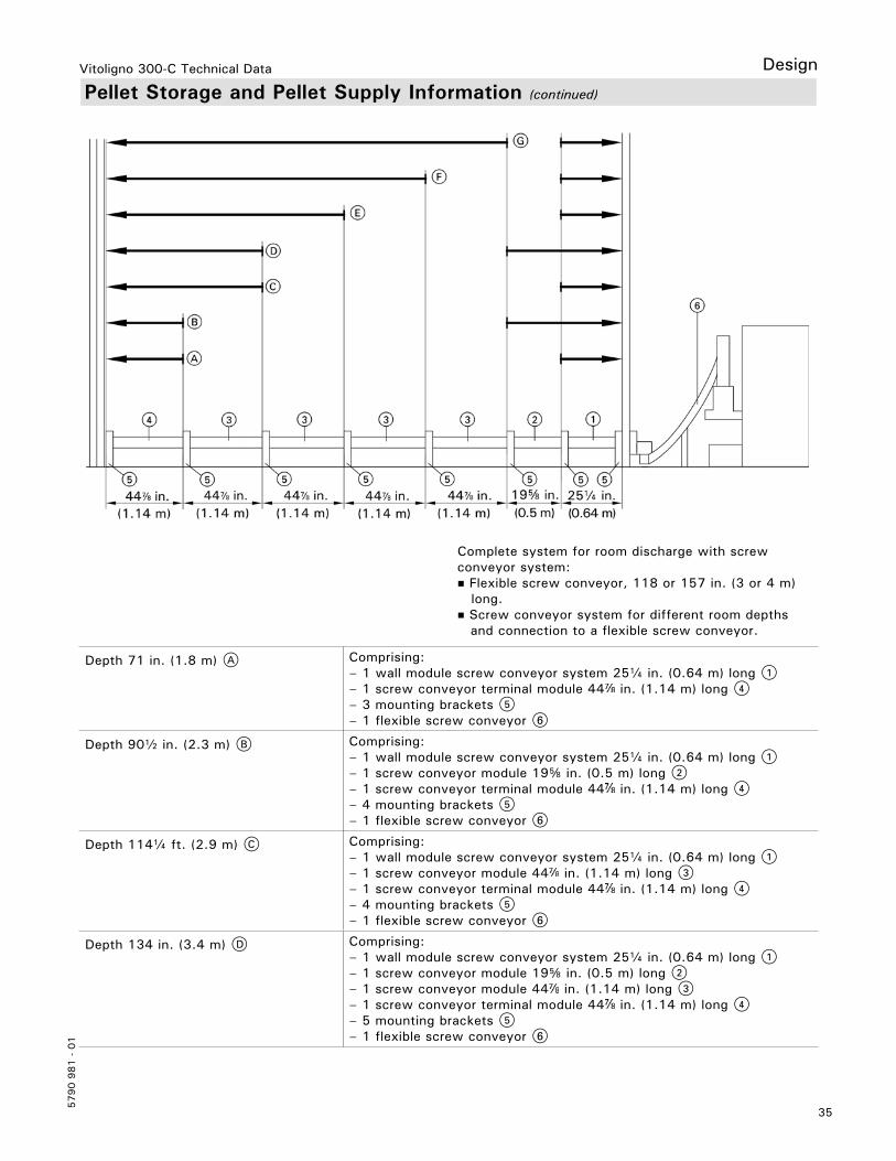
Complete system for room discharge with screw conveyor system: Flexible screw conveyor, 118 or 157 in. (3 or 4 m) long. Screw conveyor system for different room depths and connection to a flexible screw conveyor.
Depth 71 in. (1.8 m) A Comprising:– 1 wall module screw conveyor system 25a in. (0.64 m) long 1– 1 screw conveyor terminal module 44 in. (1.14 m) long 4– 3 mounting brackets 5– 1 flexible screw conveyor 6
Depth 90b in. (2.3 m) B Comprising:– 1 wall module screw conveyor system 25a in. (0.64 m) long 1– 1 screw conveyor module 19f in. (0.5 m) long 2– 1 screw conveyor terminal module 44 in. (1.14 m) long 4– 4 mounting brackets 5– 1 flexible screw conveyor 6
Depth 114a ft. (2.9 m) C Comprising:– 1 wall module screw conveyor system 25a in. (0.64 m) long 1– 1 screw conveyor module 44 in. (1.14 m) long 3– 1 screw conveyor terminal module 44 in. (1.14 m) long 4– 4 mounting brackets 5– 1 flexible screw conveyor 6
Depth 134 in. (3.4 m) D Comprising:– 1 wall module screw conveyor system 25a in. (0.64 m) long 1– 1 screw conveyor module 19f in. (0.5 m) long 2– 1 screw conveyor module 44 in. (1.14 m) long 3– 1 screw conveyor terminal module 44 in. (1.14 m) long 4– 5 mounting brackets 5– 1 flexible screw conveyor 6

Vitoligno 300-C Technical Data
5790 9
81 -
01
36
Pellet Storage and Pellet Supply Information (continued)
Design
Depth 161b in. (4.1 m) E Comprising:– 1 wall module screw conveyor system 25a in. (0.64 m) long 1– 2 screw conveyor module 44 in. (1.14 m) long 3– 1 screw conveyor terminal module 44 in. (1.14 m) long 4– 5 mounting brackets 5– 1 flexible screw conveyor 6
Depth 205 in. (5.2 m) F Comprising:– 1 wall module screw conveyor system 25a in. (0.64 m) long 1– 3 screw conveyor module 44 in. (1.14 m) long 3– 1 screw conveyor terminal module 44 in. (1.14 m) long 4– 6 mounting brackets 5– 1 flexible screw conveyor 6
Depth 252 in. (6.4 m) G(max. room depth)
Comprising:– 1 wall module screw conveyor system 25a in. (0.64 m) long 1– 4 screw conveyor module 44 in. (1.14 m) long 3– 1 screw conveyor terminal module 44 in. (1.14 m) long 4– 7 mounting brackets 5– 1 flexible screw conveyor 6
Note: Clearance for installation (depth) at least 4 in. (100) mm between the screw conveyor system and the wall.
Wall duct for screw conveyor discharge from the pellet store
LegendA Pellet sensorB Room discharge adaptor, part of the standard delivery of Vitoligno 300-C for flexible screw conveyor

37
5790 9
81 -
01
Vitoligno 300-C Technical Data
Pellet Storage and Pellet Supply Information (continued)
Design
Pellet supply via vacuum system / room discharge with screw conveyor systemCan be used if the pellet storage room is not immediately adjacent to the installation room. Pellets can be transported up to a distance of 49 ft. (15 m) and to a height differential of 197 in. (5 m). The flexible positioning of the vacuum supply system enables installations even in tight spaces.
LegendA Return air connectorB Fill connectorC DeflectorD Pressure hoseE Vacuum hoseF Vitoligno 300-C with pellet hopperG Discharge screw conveyor
Screw conveyor system for different room depths and connection to a vacuum system.
To determine the required hose length, calculate the distance between the pellet hopper connector and the pellet discharge point from the pellet storage room or the pellet silo. Use the shortest path from the storage room to the boiler. Route hoses so that they cannot be stepped on. Never kink the hoses; the smallest bending radius should be 12 in. (300 mm). Hoses should be routed as straight and level as possible. If hoses are routed up and down several times, some pellets will not be transported from the lower lying areas. Hoses must be grounded to prevent static electricity building up during pellet handling. The pellet supply hose should be made from one piece, whilst the return air hose can be made up of several pieces. The connection piece should be made of metal to ensure continuous grounding. Never expose the hoses to temperatures above 140ºF (60ºC), i.e. never route them near heating pipes or flue pipes that are not thermally insulated. Never route outdoors (risk of becoming brittle due to UV radiation).
Complete system for room discharge with vacuum system: Pellet supply hose and return air hose 7 2 in. (50 mm), roll of 49 ft. (15 m) . Max. supply hose length: 49 ft. (15 m) Max. length supply hose plus return air hose: 99 ft. (30 m) The supply hose must be made from a single piece.

Vitoligno 300-C Technical Data
5790 9
81 -
01
38
Pellet Storage and Pellet Supply Information (continued)
Design
Depth 71 in. (1.8 m) A Comprising:– 1 pellet supply and return air hose 50 ft. (15 m) long 1– 1 wall module vacuum system 25a in. (0.64 m) long 2– 1 screw conveyor terminal module 44 in. (1.14 m) long 5
Depth 90b in. (2.3 m) B Comprising:– 1 pellet supply and return air hose 50 ft. (15 m) long 1– 1 wall module vacuum system 25a in. (0.64 m) long 2– 1 screw conveyor module 19f in. (0.5 m) long 3– 1 screw conveyor terminal module 44 in. (1.14 m) long 5
Depth 114a in. (2.9 m) C Comprising:– 1 pellet supply and return air hose 50 ft. (15 m) long 1– 1 wall module vacuum system 25a in. (0.64 m) long 2– 1 screw conveyor module 44 in. (1.14 m) long 4– 1 screw conveyor terminal module 44 in. (1.14 m) long 5
Depth 134 in. (3.4 m) D Comprising:– 1 pellet supply and return air hose 50 ft. (15 m) long 1– 1 wall module vacuum system 25a in. (0.64 m) long 2– 1 screw conveyor module 19f in. (0.5 m) long 3– 1 screw conveyor module 44 in. (1.14 m) long 4– 1 screw conveyor terminal module 44 in. (1.14 m) long 5
Depth 161b in. (4.1 m) E Comprising:– 1 pellet supply and return air hose 50 ft. (15 m) long 1– 1 wall module vacuum system 25a in. (0.64 m) long 2– 2 screw conveyor module 44 in. (1.14 m) long 4– 1 screw conveyor terminal module 44 in. (1.14 m) long 5
Depth 205 in. (5.2 m) F Comprising:– 1 pellet supply and return air hose 50 ft. (15 m) long 1– 1 wall module vacuum system 25a in. (0.64 m) long 2– 3 screw conveyor module 44 in. (1.14 m) long 4– 1 screw conveyor terminal module 44 in. (1.14 m) long 5
Depth 252 in. (6.4 m) G(max. room depth)
Comprising:– 1 pellet supply and return air hose 50 ft. (15 m) long 1– 1 wall module vacuum system 25a in. (0.64 m) long 2– 3 screw conveyor module 44 in. (1.14 m) long 4– 1 screw conveyor terminal module 44 in. (1.14 m) long 5
Note: Clearance for installation (depth) at least 4 in. (100 mm) between the screw conveyor system and the wall.Wall duct for screw conveyor discharge from the pellet store
LegendA Pellet sensorB Pellet hose connector

39
5790 9
81 -
01
Vitoligno 300-C Technical Data
Pellet Storage and Pellet Supply Information (continued)
Design
Pellet supply from the pellet silo to the boiler: Pellet supply by flexible screw conveyor (screw conveyor + pellet silo)If the pellet silo is located very close to the boiler installation room.The pellets can be charged directly to the rotary lock valve via a flexible screw conveyor. A pellet hopper at the boiler is then not required.
LegendA Return air connectorB Fill connectorC Pellet siloD Flexible screw conveyor with connection to the pellet siloE Connection unit, flexible screw conveyorF Vitoligno 300-C
Pellet supply by vacuum system (vacuum system + pellet silo)Can be used if the pellet silo is not immediately adjacent to the installation room. Pellets can be transported up to a distance of 49 ft. (15 m) and to a height differential of 197 in. (5 m).
LegendA Pellet siloB Return air connectorC Fill connectorD Pressure hoseE Vacuum hoseE Vitoligno 300-CG Vacuum hoseH Pressure hose

Vitoligno 300-C Technical Data
5790 9
81 -
01
Tec
hnic
al in
form
atio
n su
bjec
t to
cha
nge
witho
ut n
otic
e.Pr
inte
d on
env
ironm
enta
lly f
riend
ly
(rec
ycle
d an
d re
cycl
able
) pa
per.
Scan for digital copy
of this document