56/588x ten inch vga colour monitor (y0f9151) - …leoromo.net/docs/cajero/personas/56-588x...
TRANSCRIPT

5.18-i
56/588X TEN INCH VGA COLOUR MONITOR (Y0F9151)
OCTOBER 1999
Contents
56/588X Ten InchVGA Colour Monitor (Y0F9151)
GENERAL DESCRIPTION....................................................................................... 5.18-1
FUNCTIONAL DESCRIPTION................................................................................ 5.18-210" CRT ................................................................................................................. 5.18-4DEGAUSSING CIRCUIT ..................................................................................... 5.18-4RGB PRE-AMPLIFIER......................................................................................... 5.18-4VIDEO AMPLIFIER ............................................................................................. 5.18-5SCAN BOARD...................................................................................................... 5.18-5
Horizontal Deflection Circuit............................................................................ 5.18-5Diode Modulator ............................................................................................... 5.18-7Vertical Deflection Circuit ................................................................................ 5.18-7
SERVICE AIDS ......................................................................................................... 5.18-8DIAGNOSTICS ..................................................................................................... 5.18-8
Linearity ............................................................................................................ 5.18-8Colour Blocks.................................................................................................... 5.18-8B/W Blocks ....................................................................................................... 5.18-8Contrast ............................................................................................................. 5.18-8Beep................................................................................................................... 5.18-9
ERROR REPORTING........................................................................................... 5.18-9STRAPPING.......................................................................................................... 5.18-9FUSES.................................................................................................................... 5.18-9ASSEMBLY AND DISASSEMBLY.................................................................... 5.18-9
Safety................................................................................................................. 5.18-9Removal of the Top Cover .............................................................................. 5.18-12Removal of the CRT ....................................................................................... 5.18-12Removal of the Scan Board............................................................................. 5.18-12Removal of the Video Amplifier Board.......................................................... 5.18-13Removal of the RGB Pre-amplifier Board...................................................... 5.18-13Removal of the Degaussing Circuit Board...................................................... 5.18-13
ADJUSTMENTS ................................................................................................. 5.18-14Test Equipment ............................................................................................... 5.18-15Set Up of the Character Generator .................................................................. 5.18-15Mode 2 (640 x 350)......................................................................................... 5.18-15Mode 3 (640 x 480)......................................................................................... 5.18-16Warm Up ......................................................................................................... 5.18-16

56/588X TEN INCH VGA COLOUR MONITOR (Y0F9151)
5.18-iiOCTOBER 1999
Horizontal Hold............................................................................................... 5.18-16Vertical Hold ................................................................................................... 5.18-16Horizontal Shift ............................................................................................... 5.18-17Horizontal Phase ............................................................................................. 5.18-17Side Pin Cushion ............................................................................................. 5.18-17Horizontal Linearity ........................................................................................ 5.18-18Horizontal Width............................................................................................. 5.18-18Vertical Linearity ............................................................................................ 5.18-18Vertical Amplitude (Mode 1) .......................................................................... 5.18-18Vertical Amplitude (Mode 2) .......................................................................... 5.18-18Vertical Amplitude (Mode 3) .......................................................................... 5.18-18Vertical Shift ................................................................................................... 5.18-18Sub-brightness ................................................................................................. 5.18-18Focus ............................................................................................................... 5.18-19Cut-Off (Black Level), G2 and White Balance Adjustment ........................... 5.18-19Overvoltage or X-Ray Radiation Protection Adjustment ............................... 5.18-19
TROUBLESHOOTING INFO ............................................................................ 5.18-20Tools and Equipment ...................................................................................... 5.18-20No Raster......................................................................................................... 5.18-21No Picture - Raster OK ................................................................................... 5.18-22Low or Loss of R, G or B................................................................................ 5.18-23Abnormal Video on CRT - Too Bright or Too Dark ..................................... 5.18-24No Blanking - Visible Retrace Line on the Back Raster................................. 5.18-25Bad Horizontal and Vertical Synchronization ................................................ 5.18-25Vertical ............................................................................................................ 5.18-26Abnormal Vertical Height in 480 Line Mode ................................................. 5.18-26Vertical Mode.................................................................................................. 5.18-27Side-Pin Cushion Distortion Failure ............................................................... 5.18-27Poor Focus....................................................................................................... 5.18-27
CONNECTOR ASSIGNMENT .......................................................................... 5.18-28Video and Sync Connector.............................................................................. 5.18-28+24 Vdc Power Input Connector..................................................................... 5.18-28115 Vac Power Input Connector ..................................................................... 5.18-28
SCHEMATIC DIAGRAMS ..................................................................................... 5.18-29
5.18-1
56/588X TEN INCH VGA COLOUR MONITOR (Y0F9151)
OCTOBER 1999
Contents
CHAPTER 5.18
56/588X Ten InchVGA Colour Monitor (Y0F9151)
GENERAL DESCRIPTIONThe 10 inch VGA colour monitor operates as a VGA compatible video displayin the NCR 56/588X Automated Teller Machines (ATMs).
Separate red, green and blue (RGB) analogue signals from the TerminalControl Module are input to the monitor, along with horizontal and verticalsynchronisation pulses.
The monitor automatically senses positive and negative polarities of bothhorizontal and vertical sync pulses in order to display the following threemodes or display formats:
The monitor operates at a horizontal line rate of 31.5 kHz and a verticalrate of 60 Hz or 70 Hz depending on the mode chosen.
The monitor is powered by a stabilized voltage of +24 Vdc +_ 0.2 Vdc sup-plied from the system power supply unit.
A separate voltage of 115 Vac supplies the automatic degaussing circuit inthe monitor.
Mode Resolution Sync. PolarityHorizontal Vertical
1 640 (H) x 400 (V) Negative Positive2 640 (H) x 350 (V) Positive Negative3 640 (H) x 480 (V) Negative Negative

56/588X TEN INCH VGA COLOUR MONITOR (Y0F9151)
5.18-2OCTOBER 1999
FUNCTIONAL DESCRIPTIONThe monitor comprises a metal enclosure containing the followingcomponents:
z 10" colour CRT with scan yokez Degaussing circuit board assemblyz RGB pre-amplifier board assemblyz Video amplifier board assemblyz Scan board assembly, comprising:
z Horizontal deflection circuitz Vertical deflection circuitz E-W diode modulator.
Refer to the diagram below and the schematic diagrams on fold outs FO-1and FO-2, at the end of this chapter, while reading the following description.

5.18-3
56/588X TEN INCH VGA COLOUR MONITOR (Y0F9151)
OCTOBER 1999
5 4 3 2 1
678910
15
14
13
12
11
V.S
YN
C.
V.C
.V
IDE
OC
ON
NE
CT
OR
H.S
YN
C.
HO
R.S
YN
C.
VA
HO
RIZ
ON
TA
LO
UT
PU
TT
RA
NS
FO
RM
ER
T2
HO
RIZ
ON
TA
LD
EF
LE
CT
ION
WIN
DIN
G
VE
RT
ICA
LD
EF
LE
CT
ION
WIN
DIN
G
G4
G1
G2
AN
OD
E
CO
NT
RA
ST
+2
4V
+1
2V
+1
2V
+1
2V
+2
4V
HO
RIZ
ON
TA
LD
RIV
ER
TR
2
HO
RIZ
ON
TA
LC
ON
TR
OL
IC2
VE
RT
ICA
LT
IME
BA
SE
IC3
B G R
RG
BR
GB
PR
EA
MP
LIF
IER
PO
SIT
IVE
/N
EG
AT
IVE
SY
NC
.S
EN
SO
RIC
1T
R3
DC
DE
GA
US
SIN
GC
IRC
UIT
G
TR
5IC
3T
R6
TR
1IC
1T
R2
B
TR
3T
R4
TR
5T
R6
RG
BA
MP
LIF
IER
TR
1T
R2
BE
AM
CU
RR
EN
TL
IMIT
ER
TR
11-
TR
12
BGR
VR
74
80
LIN
ES
85
V
E.H
.T.
25
KV
FO
CU
S(
G4
)
G2
HO
RIZ
ON
TA
LD
EF
LE
CT
ION
CIR
CU
IT
BR
IGH
TN
ES
SC
IRC
UIT
-1
40
V
HO
R.B
LA
NK
ING
FLY
BA
CK
+2
4V
+2
4V
E-
WD
IOD
EM
OD
UL
AT
OR
TR
1T
R2
TR
4
+8
5V
+8
5V
VE
RT
ICA
LB
LA
NK
ING
MO
DE
SW
ITC
HT
R2
MO
DE
SW
ITC
HT
R1
VE
RT.A
MP.C
OM
P.
HO
RIZ
ON
TA
LW
IDT
HC
OM
P.
I.C
.4
DE
GA
US
SIN
GC
OIL
F1
T1
.25
A2
50
V
24
Vd
.c.
115
Vd
.c.
+2
4V
+1
2V
BL
AN
KIN
GC
IRC
UIT
TR
6
VR
64
00
LIN
ES
VR
53
50
LIN
ES
HO
RIZ
ON
TA
LO
/P
TR
5
M2
3JG
O2
2X
X0
7
C.R
.T.
10
in.
KR
KG
KB
R
TR
3IC
2T
R4
VE
RT
ICA
LS
YN
C
56/588X TEN INCH VGA COLOUR MONITOR (Y0F9151)
5.18-4OCTOBER 1999
10" CRTThe monitor uses a 10" high resolution colour CRT.
The anode voltage (EHT) of the CRT is 22 kV, while the focus voltage(Vg3), applied to G3, is 6.5 kV to 7.9 kV. The screen grid voltage (Vg2), appliedto G2, is 420V to 900V.
The G2 voltage is derived from the horizontal deflection circuit to obtain astable voltage with respect to each of the cathodes and screen grid (G1) underall load conditions. G1 is used for brightness control, beam current limitingand horizontal and vertical blanking.
A voltage of 6.3 Vrms, derived from the deflection circuit, is applied to theheating filament.
The cathodes are driven from the RGB amplifiers on the video amplifierboard.
DEGAUSSING CIRCUITThe degaussing circuit comprises a dual PTC resistor, a degaussing coil and aprotective fuse, F1.
When ac power is applied to the degaussing circuit, the PTC resistorcauses a decreasing ac magnetizing current to be applied to the degaussingcoil. This removes any remnant magnetism from the CRT. The second part ofthe PTC resistor keeps the first part hot to minimise residual current in thedegaussing coil.
Fuse F1 is used as a protective component against any short circuits ineither the PTC resistor or the degaussing coil.
RGB PRE-AMPLIFIERAnalogue RGB video signals of 0.7 Vp-p are applied through pins 1, 2 and 3respectively of the 15 pin D-type connector, to the inverters TR1, TR5 andTR3. The signal input impedance is 75 ohms, given by R10, R50 and R30, asthe impedance of the inverters is about 10 kohms.
Referring to the G channel only (as the R and B channels are similar), theinverted signal is fed to pin 6 of the transistor array IC3, which has a hightransition frequency (typically 550 MHz). The gain of the amplifier is gov-erned by the ratio of R45 and R46 to R61 at maximum contrast. PotentiometerVR1 controls the contrast and varies the emitter current of Q1. A low imped-ance output signal of 2.5 Vp-p (maximum contrast) is provided at pins 10 and14 of IC3. TR5 and IC3 both invert the signal and as a result there is no over-all signal inversion.
A keyed horizontal clamping pulse is applied through TR7 to the RGB pre-amplifier clamping output transistors TR2, TR6 and TR4 respectively for dcrestoration of the output signal from IC3.
The pre-amplified RGB signals are fed to the video amplifier.

5.18-5
56/588X TEN INCH VGA COLOUR MONITOR (Y0F9151)
OCTOBER 1999
VIDEO AMPLIFIERThree identical video amplifiers for the R, G and B signals provide amaximum output swing of 45 Vp-p black to white to drive the cathodes of theCRT. Each amplifier contains a black level and a gain adjustment. The supplyvoltage of 85 Vdc is obtained by rectifying the positive horizontal flyback pulsefrom the line output transformer (LOPT), T2.
Referring to the G-amplifier network, transistors TR6 (common emitterstage) and TR5 (common base stage) are connected to form a cascade circuitwith relatively high input impedance, extended bandwidth and return isola-tion. The video signal is applied to the base of TR6 through the G GAINadjustment trimmer VR6 which is used for white balance adjustment. A sta-ble bias voltage of +5.1V is applied to the base of TR5 through zener diode D2.The black level for the G-gun is adjusted by altering potentiometer VR5 (GBLK LEVEL). This changes the bias of TR5 at its emitter.
The overall gain of the amplifier is formed by the ratio of collector resistorR18 and the resistor on the emitter of TR6 (R20).
The output signal directly drives the G-cathode through the protectionresistor R17.
SCAN BOARDThe scan board comprises three main circuits:
z Horizontal deflection circuitz Diode modulatorz Vertical deflection circuit.
Horizontal Deflection CircuitThe four gate EX-OR chip, IC1, operates as a horizontal and vertical syncpolarity sensor. The horizontal sync output from gate D (pin 11) remainspositive when the horizontal sync input signal is either positive or negative.Similarly with the vertical sync output from gate A (pin 3). R5, C1 and R4, C2form an integrating network with a long time constant compared to thehorizontal or vertical sync polarity time period. The output levels of gates Band C (pins 6 and 8 respectively) change from low to high when the horizontalor vertical sync polarity is positive; with negative sync polarity the gateoutputs are low.
The main functions of IC2 are:
z Horizontal oscillator (pins 14 and 16, VR1 and C10).z Sync separator (if composite sync is applied).z Two phase loops (pin 1 and pin 2).z Open collector drive pulse with constant duty cycle (pin 4).
The first phase loop (pin 17) compares the phase of the incoming horizon-tal sync pulses and the oscillator. The free running frequency of the oscillatoris set at 31.5 kHz and adjusted by VR1. The second phase (pins 2 and 3) com-pares the phase of the oscillator and the horizontal flyback pulse applied topin 2 through R19 and R29. This loop compensates for storage time variationsof the horizontal deflection transistor, TR5. VR3 adjusts the phase by injectingan additional current into the phase shifter (pin 3).

56/588X TEN INCH VGA COLOUR MONITOR (Y0F9151)
5.18-6OCTOBER 1999
R23 is the collector resistor of the open collector transistor at pin 4 of IC2.The horizontal output pulse from pin 4 drives the driver circuit which consistsof the driver transformer T1 and the driver transistor TR4. The driver stageoperates in the non-simultaneous mode; TR4 is off when TR5 is on. R26 andC19 added across the primary winding of T1 reduce the voltage peak on TR4.
The flyback tuning capacitors C25, C51 and C26 and the horizontal deflec-tion coil are connected directly across TR5. C24 is the S-correction capacitorfor symmetrical linearization and is connected in series with the deflectioncoil; while asymmetrical correction is achieved with the linearity corrector L2.C27 also serves as an additional S-correction capacitor. Diodes D20 and D21are damper diodes. L5 is the modulation coil which modulates the horizontaldeflection current for the E-W raster correction. A booster capacitor, C22, isconnected through a snubber network formed by L4, C23 and R28 at pin 5 ofT2 to avoid ringing.
The supply voltage of +24 Vdc is connected to pin 10 of the LOPT (T2)through the diode D19 and the decoupling filter network of L3 and C21. T2incorporates a three diode unit to generate the EHT of 22 kV with low internalimpedance. Two potentiometers mounted on T2 allow the focus and G2 voltageto be adjusted. A bleeder resistor is incorporated at the output of T2 (integralto the EHT lead) which acts as a pre-load on the EHT, and also discharges theCRT after switch off (for safety and to reduce spot burn-in). A high voltagecapacitor, C, is connected between the EHT and ground to avoid dynamic dis-tortion of the display at high beam currents.
Several auxiliary voltages for the B+ of the video amplifier, vertical deflec-tion circuit and the brightness control are generated by rectifying the flybackpulses sourced from T2. The CRT heater filament voltage of 6.3 Vrms issourced from pin 2 of T2 and applied via R21 on the video amplifier.
The brightness is altered by adjusting the G1 potential of the CRT, formedby R44 and VR14 and the brightness potentiometer VR13 on the scan boardusing a voltage source of -140 Vdc.
The horizontal shift adjustment allows the usable horizontal scan to becentred at the centre of the screen. Diodes D16 and D17 rectify the scan volt-age, and the resulting dc voltage, adjustable by horizontal shift potentiometerVR4, is applied to the horizontal deflection coil.
To avoid damage to the picture tube, a beam current limiter is used. A cor-rection signal, formed at the 'cold' side of the EHT winding (pin 7 of T2) and bythe network of C29, R35, R36, R37 and D24 is buffered and inverted by TR11.If the beam current exceeds the maximum allowable level (approximately 300microamps), TR12 will cease to conduct and the collector potential will gomore negative. Diode D25 will also conduct and G1 will be driven so far nega-tive that the beam current will stay at the maximum level.
Variations in the EHT internal impedance, caused by beam current varia-tions, result in picture "breathing" (picture height and width variations). Thisis compensated by applying a correction signal from the base of TR11 throughR56 to pin 9 of IC3, for vertical height compensation, and from the emitter ofTR11 to the base of TR9 via R87 for horizontal width compensation.
Horizontal and vertical blanking pulses are applied to G1 through TR6.The base of TR6 is driven by horizontal flyback pulses through D15 and verti-cal flyback pulses through D14. A zener diode, D18, provides flashover protec-tion.

5.18-7
56/588X TEN INCH VGA COLOUR MONITOR (Y0F9151)
OCTOBER 1999
Diode ModulatorThe diode modulator corrects the pin-cushion distortion in the E-W (right-left)direction of the deflection coils by modulating the horizontal scan. It is drivenby a parabolic voltage at the vertical frequency.
The parabolic signal is created by integrating the vertical sawtooth signalavailable on the sense resistor R65. The sawtooth signal is connected to thebase of TR8, coupled through R69 and R68. With the line mode changed (60/70Hz), R68 is short circuited by TR7 in order to maintain the same sawtoothamplitude. TR8 and C43 integrate the signal into a parabolic shaped correc-tion signal at the collector of TR8 which is applied to the base of TR9.
Horizontal width is effected by changing the dc reference voltage at thebase of TR9. Picture width stabilization against beam current changes ismade by applying the beam current dependent dc voltage to the base of TR9through R87. Pin cushion adjustment is made by VR11 which is connected to adc reference source derived from the resistor divider of VR12, R74 and R75.Therefore, by adjusting VR11, the horizontal width will not change as the dclevel at both ends of VR12 is effectively the same. The parabolic correction sig-nal and the dc amplitude signal are fed to the Darlington power amplifier,TR10. The supply voltage to the modulator is stabilized to +24V and filteredby R84 and C46.
Vertical Deflection CircuitThe vertical deflection circuit generates a sawtooth or ramp current which isapplied to the vertical yoke to produce vertical scanning in synchronizationwith the external sync pulses applied to the monitor.
This is performed by IC3 which incorporates the following functions:
z Synchronization circuitz Precision oscillator and ramp generatorz Power output amplifier with high current capabilityz Flyback generatorz Voltage regulatorz Precision blanking pulse generatorz Thermal shutdown protectionz CRT protection, which blanks the beam current in the event of loss of ver-
tical deflection current.
The vertical sync pulses are applied to pin 5 of IC3 from gate A of IC1, viathe network formed by D6, R47, R46 and C33. The oscillator frequency isdetermined by the RC network of R59, VR9 and C39. The vertical hold poten-tiometer, VR9, adjusts the oscillator frequency.
The supply voltage of +24 Vdc is applied to pin 14 through the filter net-work of R51 and C36. C34 is the flyback capacitor which connects the outputof the flyback generator (pin 15) to pin 2 which is the supply voltage of thepower output stage. During the trace time the supply voltage is obtained viaD7, while during the retrace time it is obtained from the flyback generator.
The output of the power amplifier (pin 1) drives the vertical windings ofthe yoke. Pin 12 is the inverting input of the amplifier. The network R64 andR62 defines the dc level across C42 to allow the correct centring of the outputvoltage. The series network of R63 and C41, in conjunction with R62 and R64,applies a small part of the parabola available across C42, and the ac-feedbackvoltage taken across R65, to the feedback input of pin 12.
56/588X TEN INCH VGA COLOUR MONITOR (Y0F9151)
5.18-8OCTOBER 1999
For the vertical shift, a dc current is injected at the 'cold' side of the verti-cal coils. This is obtained by means of a resistor divider, VR10, between thevertical supply voltage and ground.
The linearity control, VR8, is obtained by applying feedback between theoutput of the buffer stage, pin 10, and the tapping of capacitors C37 and C38.C38 is connected to pin 9 of IC3, which is the input to the buffer stage.
Vertical height is adjusted by VR7 for mode 3 (60 Hz). The vertical heightcompensation for modes 1 and 2, VR5 and VR6 respectively, are adjustedwhen the transistors TR2 and TR1 are switched on by output gates C and B ofIC1.
NOTE: VR7 must be adjusted first before adjusting VR5 and VR6.
Vertical blanking is obtained from the output of the vertical blanking gen-erator, pin 13, and is summed with the horizontal blanking at the junction ofD14 and D15 to produce the blanking signal.
SERVICE AIDS
DIAGNOSTICSThere are no Level 0 diagnostics for the CRT.
The level 1 Graphics/Video diagnostic tests enable the monitor to be testedand calibrated.
The tests offered are as follows:
z Linearityz Colour Blocksz B/W Blocksz Contrastz Beep
With the exception of the Beep test, all the tests can be cancelled by select-ing the CNCL option. Looping is only allowed on the Beep test.
LinearityWhen the Linearity test is selected the H character is displayed in allpositions on the CRT.
Colour BlocksThe Colour Blocks test is used to verify the overall graphic colour quality anddisplays colour bars on the CRT.
B/W BlocksThe B/W Blocks test displays four alternate black and white blocks on theCRT.
ContrastThe Contrast test displays a white screen and black border, and is used to setup balance, brightness and tint.

5.18-9
56/588X TEN INCH VGA COLOUR MONITOR (Y0F9151)
OCTOBER 1999
BeepThe Beep test emits a beep tone.
ERROR REPORTINGThere is no error reporting applicable to the CRT.
STRAPPINGAll jumpers are implemented with zero ohm resistors and should not beremoved.
FUSESThere are two fuses on the monitor:
z F1 on the scan board is rated at 2.5A, 250V.z F1 on the degaussing circuit board is rated at 1.25A, 250V.
ASSEMBLY AND DISASSEMBLY
SafetyRead the following safety notes carefully before attempting to service themonitor.
The scan board generates extremely high voltages for the CRT, in particu-lar:
z 22 kV for the final anodez 6 kV for the focus grid.
Therefore great care must be taken when handling the scan board andvideo amplifier.
WARNING
The CRT anode retains a potentially lethal voltage even whenthe monitor is turned off. The following procedure mustALWAYS be observed prior to disconnection of the EHT cap orany other task which requires the CRT to be handled:
1. Connect a clip lead or heavy gauge wire to chassis ground.2. Connect the other end of the lead to the shaft of a flat blade screwdriver
that has an insulated handle.

56/588X TEN INCH VGA COLOUR MONITOR (Y0F9151)
5.18-10OCTOBER 1999
3. Keeping well clear of both the wire and the screwdriver shaft, insert theblade of the screwdriver under the EHT cap and make contact with theanode terminal. Depending on the amount of charge present on the anode,a distinct snap may be heard as the CRT discharges.
It should be noted that despite correct performance of the CRT dischargeprocedure, the CRT bulb capacitance can accumulate charge as the dischargestresses are relaxed. It follows, therefore, that ELECTRIC SHOCK HAZARDIS EVER PRESENT WHEN HANDLING THE CRT.
The following guidelines must also always be observed:
z Do not dispose of the CRT by breaking it, unless wearing safety glassesand protective clothing.
z If it becomes necessary to remove the CRT from it's mountings within themonitor, under no circumstances should leverage be applied to the CRT.
z Never apply pressure or leverage to the tension band. If the tension bandis moved it will reduce or remove the implosion protection.
NOTE: Before opening any part of the monitor, remove the power cable fromthe connector on the rear of the monitor.
The monitor includes critical mechanical and electrical parts which areessential for X-radiation safety. Replace all critical components (marked witha '!') only with the exact replacement parts named in the Parts IdentificationManual.
Refer to the exploded view of the monitor assembly on fold out FO-3 at therear of this chapter, and the interconnection assembly diagram shown below,while following the removal procedures. Numbers in brackets refer to theinterconnecting wire numbers as shown in the diagram below.

5.18-11
56/588X TEN INCH VGA COLOUR MONITOR (Y0F9151)
OCTOBER 1999
NOTE: Assembly of the monitor is the reverse of the disassembly proce-dures.
V.C
.V
IDE
OC
ON
NE
CT
OR
GN
DL
2H
.LIN
.
SC
AN
BO
AR
D
SB
EH
T
T2
TR
AN
SF
OR
ME
R
1 2
VR
1H
.HO
LD
P1
P2
G1
G2
G4
VR
1V
R2
VR
3V
R4
VR
5\
VR
6
=B
BL
K-
LE
VE
L=
BG
AIN
=R
BL
K-
LE
VE
L=
RG
AIN
=G
BL
K-
LE
VE
L=
GG
AIN
VA
DEFLECTIONWINDING
CR
T1
0in
.
E.H
.T.2
2K
V
KG
KR
DC B
A
T1
.25
A2
50
V
115
Va
.c.
PT
C
F1
IEC
CO
NN
EC
TO
R
AD
AP
TE
RR
GB
PR
EA
MP
LIF
IER
RG
B
12V
GND
V.
H.
BLANKING
CO
NT
RA
ST
INP
UT
SIG
NA
L
IC3
VR
8V
.LIN
.V
R3
H.P
HA
SE
B
14
G1
FIL
12V
GND
85V
IC2
VA
VID
EO
AM
PL
IFIE
R
VR
5V
R3
VR
1
VR
6V
R4
VR
2
VR
71
00
LIN
ES
VR
61
00
LIN
ES
VR
53
50
LIN
ES
V.A
MP.
VR10V.SHIFT V
R9
V.H
OL
D
P3
C
VR
11E
.W.
VR
12
H.W
IDT
H
VR
14
SU
BB
RIG
HT.
VR
1
B
16
FO
CU
SG
2
F1
T2
.5A
25
0V
A
1 6
VR
2
OV
ER
VO
LTA
GE
PR
OJE
CT
ION
VR
13
BR
IGH
T
15
D VR
15
FO
CU
SV
R1
6G
2
INP
UT
24
V
VID
EO
AM
PL
IFIE
R
DE
GA
US
SIN
GC
OIL D
EG
AU
SS
ING
CIR
CU
IT
G2
VR
4H
.SH
IFT
KBB R G G
ND
37
6\
48
1
5
2

56/588X TEN INCH VGA COLOUR MONITOR (Y0F9151)
5.18-12OCTOBER 1999
Removal of the Top CoverUnscrew the six screws located on the top of the monitor and then lift off thecover.
Removal of the CRTThe CRT is removed as follows:
1. Disconnect the power to the monitor.2. Remove the top cover.3. Discharge the anode by following the CRT discharge procedure detailed
above. Remove the EHT cap from the anode of the CRT.4. Unscrew the four screws which attach the left hand plate to the monitor.
Slide the plate towards the rear of the monitor and remove it by tilting itoutwards from the front of the monitor.
5. Remove the video amplifier board from the CRT base.6. Remove the CRT ground wire (8), connected to the CRT braid, from the
video amplifier board.7. Disconnect the deflection yoke wiring harness (7) from the connector B on
the scan board.8. Disconnect the degaussing coil leads (11) from the connector B on the
degaussing circuit board.9. Unscrew the four hex nuts, one in each corner of the CRT, and gently pull
the CRT forwards out of the casing.
Removal of the Scan BoardThe scan board is removed as follows:
1. Disconnect the power to the monitor.2. Remove the top cover.3. Discharge the anode by following the CRT discharge procedure detailed
above. Remove the EHT cap from the anode of the CRT.4. Unscrew the four screws which attach the left hand plate to the monitor.
Slide the plate towards the rear of the monitor and remove it by tilting itoutwards from the front of the monitor.
5. Disconnect the following wires:z The wiring harness (7) from the connector B on the scan board.z The wiring harness (6) from the connector C on the scan board.zzThe wiring harness (4) from the connector A on the scan board.
6. Remove the scan board by lifting it off the three stand-offs on the left handplate and unscrewing the fourth stand-off which attaches the scan boardto the LOPT (T2).
7. Desolder the G2 (screen grid) lead on the scan board and the G4 (focus)lead from under the insulating cover on the CRT.
8. Disconnect the wiring harness (5) from connector D and the ground lead(3) from the GND tab on the scan board.
5.18-13
56/588X TEN INCH VGA COLOUR MONITOR (Y0F9151)
OCTOBER 1999
Removal of the Video Amplifier BoardThe video amplifier board is removed as follows:
1. Disconnect the power to the monitor.2. Remove the top cover.3. Discharge the anode by following the CRT discharge procedure detailed
above. Remove the EHT cap from the anode of the CRT.4. Unscrew the four screws which attach the left hand plate to the monitor.
Slide the plate towards the rear of the monitor and remove it by tilting itoutwards from the front of the monitor.
5. Remove the video amplifier board from the CRT base, and disconnect thefollowing:z The wiring harness (5) from the connector D on the scan board.z The wiring harness (2) from the connector B on the RGB pre-amplifier
board.z The ground connection lead (3) from the GND tab on the scan board.z The ground connection lead (8) from the ground tab on the video
amplifier board.z The focus lead (10) from the CRT socket on the video amplifier board.zzThe G2 lead (11) from the video amplifier board.
Removal of the RGB Pre-amplifier BoardThe RGB pre-amplifier board is removed as follows:
1. Disconnect the power to the monitor.2. Remove the top cover.3. Disconnect the wiring harness (4) from the connector A on the scan board.4. Disconnect the wiring harness (2) from the connector B on the RGB pre-
amplifier board.5. Remove the two locking screws which hold the 15 pin D-type connector to
the rear plate.
Removal of the Degaussing Circuit BoardThe degaussing circuit board is removed as follows:
1. Disconnect the power to the monitor.2. Remove the top cover.3. Disconnect the degaussing coil by removing the degaussing leads from the
connector B on the degaussing circuit board.4. Disconnect the 115 Vac mains lead (9) from the connector A on the
degaussing circuit board.5. Lift the degaussing circuit board off the two stand-offs.

56/588X TEN INCH VGA COLOUR MONITOR (Y0F9151)
5.18-14OCTOBER 1999
ADJUSTMENTSIn the event of repair and/or revision to the monitor, the adjustmentprocedures detailed below should be followed.
NOTE: The adjustable parameters are to some extent interactive and it maybe necessary to repeat sections of the procedure to obtain optimum results.
The interconnection assembly diagram shown previously details all theadjustable devices and their locations on the assembly boards. The metalplates diagram below shows the locations of the controls and the connectors.
BRIGHTSUB BRIGHT
V.HOLD.
H.WIDTH
H.LIN.
H.PHASE
V.LIN.
REAR PLATETOP VIEW WITH TOP COVER
REMOVED
H.HOLD.
H.SHIFT
SERVICE V.SHIFT
V.HEIGHT350 400 480
V.PROTECT
DC
VA
SB
RGB
+-
DEGAUSSINGCOIL
115VACSIGNALINPUT 24V
SIGNALINPUT
115VACDEGAUSSING24V
+-CONTRAST
G2FOCUS
E.W.CORRECTION
LEFT HAND PLATEREMOVABLE

5.18-15
56/588X TEN INCH VGA COLOUR MONITOR (Y0F9151)
OCTOBER 1999
Test EquipmentTo carry out the adjustments, the following equipment is required:
z Digital multimeter to measure up to 2000 Vdc.z Quantum colour character generator, model 801C.z TV colour analyser.z Non-inductive screwdriver for horizontal linearity adjustment.z Insulated screwdriver for other adjustments.z Stabilized power supply of 24 Vdc +_0.2 Vdc at 2 amps, and 115 Vac 50/60
Hz mains source for the automatic degaussing circuit.z Degaussing coil.
NOTE: For adjustments with the monitor installed in the host terminal, thecharacter generator and the power supply/mains source will not berequired.
In this case, the three modes of operation are obtained by running thediagnostics tests for the monitor to produce the most appropriate test pattern.
Set Up of the Character GeneratorThe Quantum character generator is set up to obtain the following data:
Mode 1 (640 x 400)
z Horizontal:z Dots/char. = 8z Total chars. = 100z Displayed chars. = 80z Drive delay = 82z Drive width = 12
z Vertical:z Lines/char. = 12z Total lines/char. = 453z Displayed rows = 32z Drive delay = 34z Drive width = 9
z Hz = 69.48z kHz = 31.475z MHz = 25.176z Horizontal sync = -vez Vertical sync = +ve.
Mode 2 (640 x 350)
z Horizontal:z Dots/char. = 8z Total chars. = 100z Displayed chars. = 80z Drive delay = 81z Drive width = 12
z Vertical:z Lines/char. = 12z Total lines/char. = 453

56/588X TEN INCH VGA COLOUR MONITOR (Y0F9151)
5.18-16OCTOBER 1999
z Displayed rows = 28z Drive delay = 32z Drive width = 9
z Hz = 69.47z kHz = 31.475z MHz = 25.176z Horizontal sync = +vez Vertical sync = -ve.
Mode 3 (640 x 480)
z Horizontal:z Dots/char. = 8z Total chars. = 100z Displayed chars. = 80z Drive delay = 82z Drive width = 12
z Vertical:z Lines/char. = 12z Total lines/char. = 525z Displayed rows = 39z Drive delay = 40z Drive width = 2
z Hz = 59.95z kHz = 31.475z MHz = 25.176z Horizontal sync = -vez Vertical sync = -ve.
Warm UpApply power to the power input connector. Apply the cross hatch test pattern,mode 3, to the 15 pin D-connector.
Allow the monitor to warm up for 20 minutes before making any adjust-ments. If the monitor is powered up from 'cold', its automatic degaussing sys-tem will demagnetize the CRT. If, however, the monitor is powered up from its'warm' state and has been moved around, an external degaussing is required.
Set the CONTRAST control to 75% of it's maximum, and the BRIGHT con-trol so that no background raster appears. If no image is obtained, refer to thesection headed "TROUBLESHOOTING INFO".
Horizontal Hold
1. Short together the two test pins marked P1 and P2 on the scan board.2. Adjust VR1 (H. HOLD) on the scan board, until the entire display drifts
slowly across the screen.
Vertical HoldAdjust VR9 (V. HOLD) on the scan board, so that the display gets locked whenit is rolling from the top to the bottom of the screen.

5.18-17
56/588X TEN INCH VGA COLOUR MONITOR (Y0F9151)
OCTOBER 1999
Horizontal Shift
1. Adjust VR14 (SUB. BRIGHT) on the scan board so that the backgroundraster is visible.
2. Adjust VR4 (HOR. SHIFT) to horizontally centre the raster on the screen.If the raster is too wide, reduce its width by altering VR12 (HOR. WIDTH)on the scan board.
3. If VR14 (SUB. BRIGHT) was moved, readjust it to obtain -10 Vdc +_2 Vdc,measured between one end of VR13 (BRIGHT) on the scan board, that isjumper J23, and GND.
4. If VR12 (HOR. WIDTH) was moved, readjust it so that the horizontal sizeof the display, measured along the centre of the screen, is 180 mm +_2mm.
Horizontal Phase
1. Set the brightness control (VR9, BRIGHT) to maximum so that the back-ground raster is visible. If the background raster is not visible, adjustVR14 (SUB. BRIGHT) on the scan board until it appears.
2. Adjust VR3 (HOR. PHASE) so that the image is at the centre of the screen(see diagram below).
3. If VR14 (SUB. BRIGHT) was moved, readjust it to obtain -10 Vdc +_2 Vdc,measured between one end of VR13 (BRIGHT) on the scan board, that isjumper J23, and GND.
Side Pin CushionAdjust VR11 (E.W.) on the scan board to correct any side pin cushion effects(curved or bowed edges of the display).
a ) 2.5
4
b )
NOTE: Total error must extend over half the
horizontal and vertical amplitude.
Geometric DistortionZone of Uncertainty
2.5mm
C.R.T. Screen
Centre Point
Centre Circle
+ 2130 mm-
180 mm+- 2

56/588X TEN INCH VGA COLOUR MONITOR (Y0F9151)
5.18-18OCTOBER 1999
Horizontal LinearityUsing a non-inductive screwdriver, adjust V2 (HOR. L. LIN) on the scanboard, until the corresponding vertical columns of the cross hatch pattern areof equal width, measured along the centre of the screen.
NOTE: Horizontal linearity is interactive with horizontal width, thereforeboth HOR. V. LIN and HOR. WIDTH may require adjustment.
Horizontal WidthAdjust VR12 (HOR. WIDTH) on the scan board, so that the horizontal size ofthe display measured along the centre of the screen (assuming that the sidepin-cushion and the geometry distortion is correctly adjusted) is 180 mm +_2mm.
Vertical LinearityAdjust VR8 (VERT. V. LIN) on the scan board, so that the horizontal rows ofthe cross hatch pattern, on the upper and lower halves of the screen, are ofequal height.
NOTE: Horizontal linearity is interactive with horizontal width, thereforeboth HOR. V. LIN and HOR. WIDTH may require adjustment.
Vertical Amplitude (Mode 1)
1. Apply mode 1 to the monitor.2. Adjust VR6 (VERT. AMP. - 400 LINES) on the scan board, so that the ver-
tical size of the display, measured along the centre of the screen, is 130mm +_2 mm.
Vertical Amplitude (Mode 2)
1. Apply mode 2 to the monitor.2. Adjust VR5 (VERT. AMP. - 350 LINES) on the scan board, so that the ver-
tical size of the display, measured along the centre of the screen, is 130mm +_2 mm.
Vertical Amplitude (Mode 3)
1. Apply mode 3 to the monitor.2. Adjust VR7 (VERT. AMP. - 480 LINES) on the scan board, so that the ver-
tical size of the display, measured along the centre of the screen, is 130mm +_2 mm.
Vertical ShiftAdjust VR10 (VERT. SHIFT) on the scan board, so that the display isvertically centred on the screen.
Sub-brightnessAdjust VR14 (SUB. BRIGHT) to obtain -10 Vdc +_2 Vdc, measured betweenone end of VR13 (BRIGHT) on the scan board, that is jumper J23, and GND.

5.18-19
56/588X TEN INCH VGA COLOUR MONITOR (Y0F9151)
OCTOBER 1999
Focus
1. Apply the 'H' pattern to the monitor.2. Set VR1 (CONTRAST) on the RGB pre-amplifier board, to 75% of it's max-
imum.3. Adjust VR13 (BRIGHT) on the scan board to 75% of its maximum.4. Adjust VR15 (FOCUS) on the scan board for the best focus over the entire
screen.
Cut-Off (Black Level), G2 and White Balance Adjustment
1. Set the following potentiometers on the video amplifier board fully clock-wise (viewed from the top):z VR1 - B. BLK. LEVELz VR2 - B. GAINz VR3 - R. BLK. LEVELz VR4 - R. GAINz VR5 - G. BLK. LEVELzzVR6 - G. GAIN
2. Ensure that the sub-brightness is adjusted as described in the sectionheaded "Vertical Amplitude (Mode 1)".
3. Set the BRIGHT control to maximum. Set the CONTRAST control (VR1on the RGB pre-amplifier board) so that there is a signal of 28 Vp-p (blackto white) at the collector of TR6 on the video amplifier board.
4. Set the screen grid (G2) potentiometer, VR16 on the scan board, to mini-mum.
5. Remove the test signal from the monitor by unplugging the signal cablefrom the D-type connector.
6. Short circuit test points P4 and P5 on the scan board.7. Slowly adjust VR16 until one colour becomes visible. Take this colour as
the reference colour for the cut-off adjustment.8. Selecting any colour other than the reference colour, adjust the relevant
black level control (VR1, VR3 or VR5), until it is as bright as the referencecolour.
9. Remove the short between P4 and P5.10. Apply a full white page signal. Set the brightness control to give 60 Nits
using a luminance meter.11. Adjust the VR2, VR4 and VR6 (GAIN) on the video amplifier board to
obtain the required white balance of 9300 K.12. Readjust VR13 (BRIGHT) to give 80 Nits +_5%
Overvoltage or X-Ray Radiation Protection Adjustment
1. Connect a voltmeter between test point P3 on the scan board and ground.2. To check that the overvoltage circuit functions, set VR2 on the scan board
fully anti-clockwise so that the voltage at the test point is about 5.7V.Adjust VR2 until the voltage at the test point reaches 8.0V, the monitorshould switch off. Remove the 24 Vdc supply to the monitor and turn VR2fully anti-clockwise. Apply the 24 Vdc supply.
3. Turn VR1 (CONTRAST) on the RGB pre-amplifier board to minimum sothat there is no display on the screen.
4. Adjust VR2 so that the voltage at test point P3 is 6.8V +0V/-0.1V.

56/588X TEN INCH VGA COLOUR MONITOR (Y0F9151)
5.18-20OCTOBER 1999
TROUBLESHOOTING INFO
Tools and EquipmentTo troubleshoot the monitor, the following tools and equipment are required:
z Digital multimeter to measure up to 2000 Vdc.z Quantum colour character generator model 801C.z Stabilized power supply of 24 Vdc +_0.2 Vdc at 2 amps, and 115 Vac 50/60
Hz mains source for the automatic degaussing circuit.z Non-inductive screwdriver and insulated screwdriver for adjustments
where required.z Dual trace scope with 10:1 probes.z 110/115 Vac 50/60 Hz mains source.
NOTE: For adjustments with the monitor installed in the host terminal, thecharacter generator and the power supply will not be required.
WARNING
The CRT anode retains a potentially lethal voltage even whenthe monitor is turned off. The EHT discharge proceduredetailed in the safety section under the heading "ASSEMBLYAND DISASSEMBLY" must ALWAYS be observed prior to dis-connection of the EHT cap or any other task which requiresthe CRT to be handled.
The following flowchart is a guide to troubleshooting the monitor.
5.18-21
56/588X TEN INCH VGA COLOUR MONITOR (Y0F9151)
OCTOBER 1999
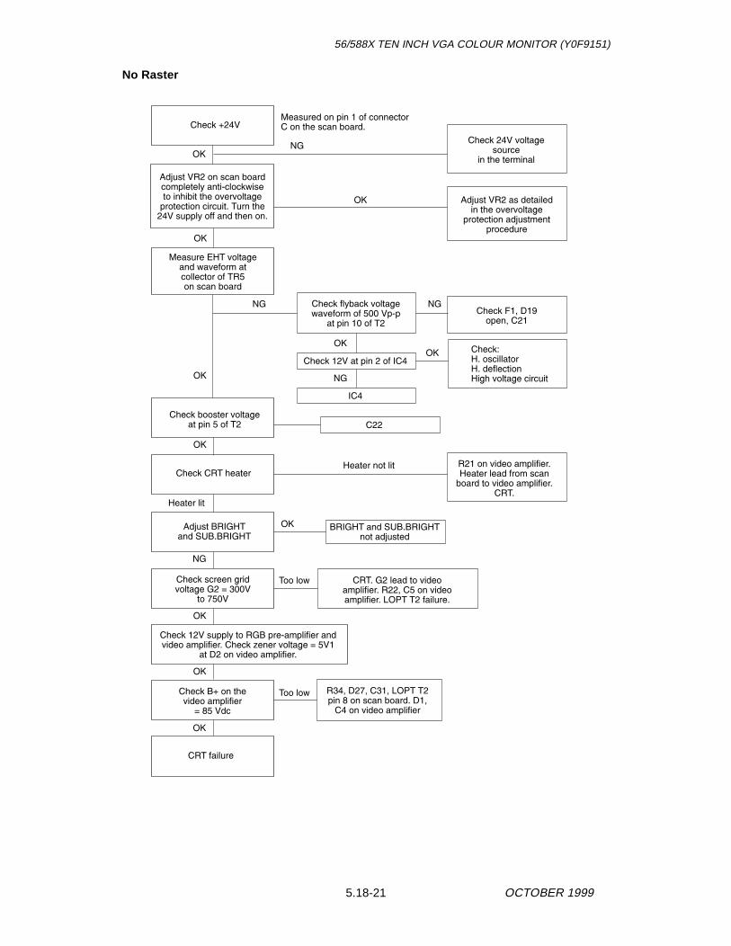
No Raster
Check +24V
OK
NG
Heater not lit
BRIGHT and SUB.BRIGHTnot adjusted
NG NG
NG
NG
OK
OK
OK
OK
OK
OK
OK
OK
CRT failure
Adjust BRIGHTand SUB.BRIGHT
Check CRT heater
Check:H. oscillatorH. deflectionHigh voltage circuit
Check 12V at pin 2 of IC4
IC4
Heater lit
Too low
Too low
Measured on pin 1 of connectorC on the scan board.
Check 24V voltagesource
in the terminal
Measure EHT voltageand waveform atcollector of TR5on scan board
Adjust VR2 on scan boardcompletely anti-clockwiseto inhibit the overvoltage
protection circuit. Turn the24V supply off and then on.
OK
Check flyback voltagewaveform of 500 Vp-p
at pin 10 of T2
Check F1, D19open, C21
Adjust VR2 as detailedin the overvoltage
protection adjustmentprocedure
OK
Check booster voltageat pin 5 of T2 C22
Check screen gridvoltage G2 = 300V
to 750V
CRT. G2 lead to videoamplifier. R22, C5 on videoamplifier. LOPT T2 failure.
Check 12V supply to RGB pre-amplifier andvideo amplifier. Check zener voltage = 5V1
at D2 on video amplifier.
Check B+ on thevideo amplifier
= 85 Vdc
R34, D27, C31, LOPT T2pin 8 on scan board. D1,
C4 on video amplifier
R21 on video amplifier.Heater lead from scan
board to video amplifier.CRT.

56/588X TEN INCH VGA COLOUR MONITOR (Y0F9151)
5.18-22OCTOBER 1999
No Picture - Raster OK
NG
OK
NG
NG
OK
OK
CRT cathode failure
Check connection betweenterminal and monitor
Check no flyback atC30 on video amplifier.
TR7 failed.
Check D1, C3, C4 onvideo amplifier.
No 85V B+.
Check RGB output atcollectors of TR1,TR3 and TR5 onvideo amplifier
Check RGB input atJ9, J8 and R30 on the
RGB pre - amplifier= 0.7 Vp - p
Check RGB output atconnector B pins 2, 3, 1on RGB pre - amplifier-
--
5.18-23
56/588X TEN INCH VGA COLOUR MONITOR (Y0F9151)
OCTOBER 1999
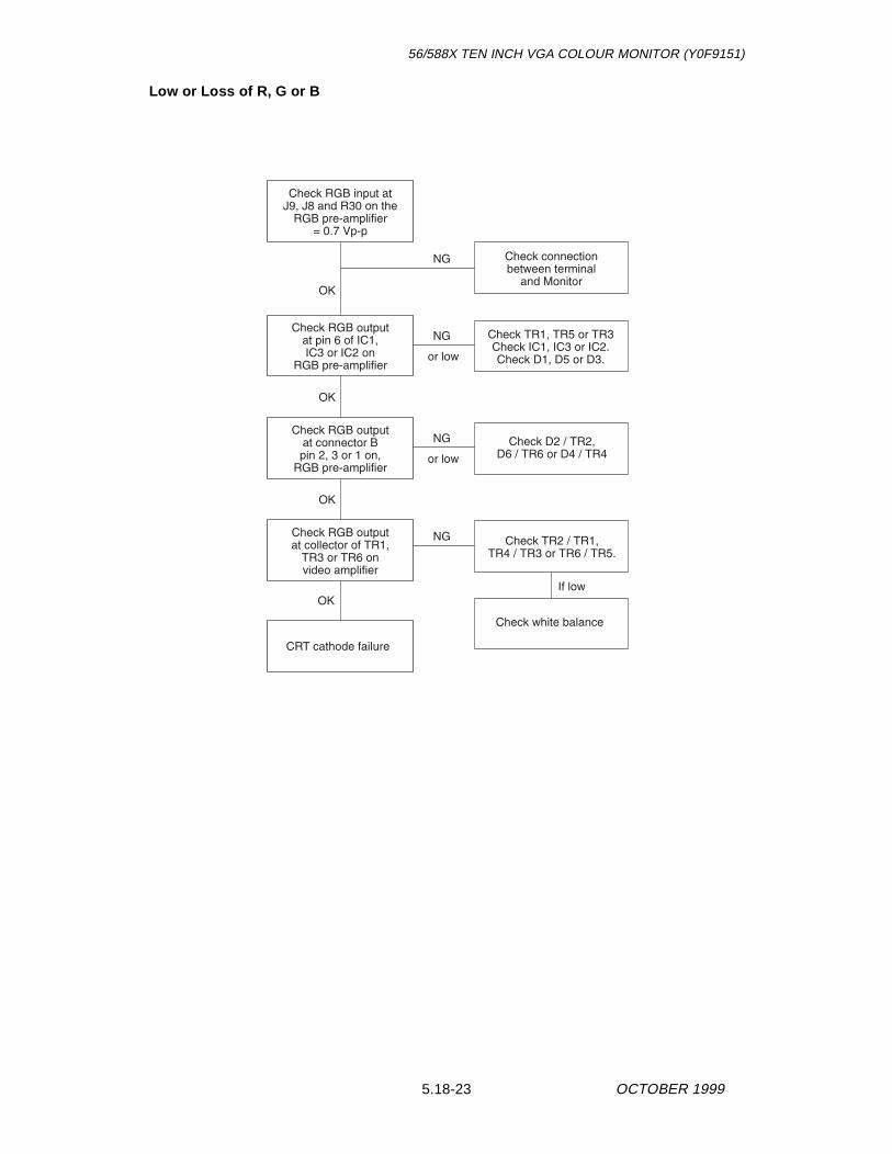
Low or Loss of R, G or B
NG
Check white balance
NG
or low
NG
or low
NG
If low
OK
OK
OK
OK
CRT cathode failure
Check connectionbetween terminal
and Monitor
Check RGB outputat connector Bpin 2, 3 or 1 on,
RGB pre-amplifier
Check TR2 / TR1,TR4 / TR3 or TR6 / TR5.
Check D2 / TR2,D6 / TR6 or D4 / TR4
Check TR1, TR5 or TR3Check IC1, IC3 or IC2.Check D1, D5 or D3.
Check RGB outputat collector of TR1,
TR3 or TR6 onvideo amplifier
Check RGB input atJ9, J8 and R30 on the
RGB pre-amplifier= 0.7 Vp-p
Check RGB outputat pin 6 of IC1,IC3 or IC2 on
RGB pre-amplifier

56/588X TEN INCH VGA COLOUR MONITOR (Y0F9151)
5.18-24OCTOBER 1999
Abnormal Video on CRT - Too Bright or Too Dark
Check video input
Check video output
OK
NG
NG
NG
Too low
OK
OK
OK
Adjust BRIGHT andSUB. BRIGHT
controls
OK
OK
Check screenvoltage VG2
Low or 0V
Measured at connector Bon RGB pre-amplifier
Check RGB outputat collectors of TR1,
TR3 and TR5 onvideo amplifier
Check video bias at D2,+12V on video amplifier
Check B+ = 85 Vdcon video amplifier
R34, D27, C31, on scan board.D1, C3, C4 on video amplifier
Check brightnesscircuit on G1 and
- 140V lines
R33, D26, C30, D18,TR6 on scan board
300 to 700VCRT failure
-
TR7 faulty, +12V onRGB pre-amplifier
CRT, C5, T2 LOPT

5.18-25
56/588X TEN INCH VGA COLOUR MONITOR (Y0F9151)
OCTOBER 1999
No Blanking - Visible Retrace Line on the Back Raster
Bad Horizontal and Vertical Synchronization
Horizontal
OK
OK
NG
NG
Check blankingcircuit
Check H.flyback andV.flyback at
R22 and R20 onscan board.
Check D14, D15, TR6and D18. No 85V.
If no H.flybackT2 LOPT
If no V.flyback IC3
Check H and Vblanking at collector ofTR6 on video amplifier
OK
Checksynchronization
input circuit
NG
IC2, C10, C4
OK
NG
NG
Check connectionbetween terminal and
monitor. Check R2, D3, D1on scan board
Check H.sync. atcollector of TR3on scan board
Check H.sync. input,pin 12 of IC1 on
scan board
IC1, TR3, D2 onscan board. Check
+5V on pin 14 of IC1.
NG
Adjust HOR.HOLDVR1 on scan board

56/588X TEN INCH VGA COLOUR MONITOR (Y0F9151)
5.18-26OCTOBER 1999
Vertical
Abnormal Vertical Height in 480 Line Mode
NG
Check V. sync. atpin 5 of IC3
OK
NG
NG
Check verticaloscillator circuit
Check V. sync inputpin 1 of IC1 on
scan board
Adjust V. HOLD, VR9on scan board
Check connectionbetween terminal andmonitor. Check R3, D5and D4 on scan board
IC3, C39, D8
Low
Check verticaldeflection circuit
Check 24 Vdc line
Failure of TR1 or TR2or see Vertical Mode
section, below
Measured after R51 on scan board
R51, C36, R43on scan board
Check vertical modecircuit by adjusting
VR4, VR5, or removingTR1, TR2
Failure of IC3,vertical deflection coil,
C34, R65, D7.
Readjust VR7( VERT. AMP480 LINES )
on scan board

5.18-27
56/588X TEN INCH VGA COLOUR MONITOR (Y0F9151)
OCTOBER 1999
Vertical Mode
Side-Pin Cushion Distortion Failure
Poor Focus
-
-
Vertical ModeFailure condition:
Too small Vertical Heightat 400 lines and 350 linesVibrating Vertical Height
Check IC1, TR1, TR2,D2 on scan board
Readjust VR5 ( VERT.AMP. 350 LINES )
and VR6 ( VERT.AMP.400 LINES )
ReadjustE.W., VR11
on scan board
No field parabola at base ofTR8 on scan board
Failure of: D22, TR8, C43,C44, TR9, R84, C46, TR10
Readjust FOCUS control,VR15 on scan board.
NG
Failure of focus control circuit,focus lead, CRT socket or CRT

56/588X TEN INCH VGA COLOUR MONITOR (Y0F9151)
5.18-28OCTOBER 1999
CONNECTOR ASSIGNMENT
Video and Sync ConnectorVideo and sync data is input to the top of the monitor through a 15 pin D-typeconnector with the following pinout:
+24 Vdc Power Input Connector+24 Vdc and its return (GND) is input to a two pin Molex connector on the topof the monitor. The pinout is as follows:
115 Vac Power Input Connector115 Vac is input to a three pin IEC 320 connector on the top of the monitor.The pinout is as follows:
1
2
+24V RTN
+24V
L
N
E
LIVE
NEUTRAL
EARTH

5.18-29
56/588X TEN INCH VGA COLOUR MONITOR (Y0F9151)
OCTOBER 1999
SCHEMATIC DIAGRAMSFold-out sheet FO-1 details the schematic diagram for the monitor and fold-out sheet FO-2 details the schematic diagram for the RGB Pre-amplifier. Fold-out sheet FO-3 details the exploded view of the monitor assembly.

56/588X TEN INCH VGA COLOUR MONITOR (Y0F9151)
5.18-30OCTOBER 1999