555 timer ic and opamp.doc
TRANSCRIPT

555 timer ICFrom Wikipedia, the free encyclopediaJump to: navigation, search
NE555 from Signetics in dual-in-line package
Internal block diagram
The 555 Timer IC is an integrated circuit (chip) implementing a variety of timer and multivibrator applications. The IC was designed by Hans R. Camenzind in 1970 and brought to market in 1971 by Signetics (later acquired by Philips). The original name was the SE555 (metal can)/NE555 (plastic DIP) and the part was described as "The IC Time Machine".[1] It has been claimed that the 555 gets its name from the three 5 kΩ resistors used in typical early implementations,[2] but Hans Camenzind has stated that the number was arbitrary.[3] The part is still in wide use, thanks to its ease of use, low price and good stability. As of 2003, it is estimated that 1 billion units are manufactured every year.[3]
Depending on the manufacturer, the standard 555 package includes over 20 transistors, 2 diodes and 15 resistors on a silicon chip installed in an 8-pin mini dual-in-line package (DIP-8).[4] Variants available include the 556 (a 14-pin DIP combining two 555s on one chip), and the 558 (a 16-pin DIP combining four slightly modified 555s with DIS & THR connected internally, and TR falling edge sensitive instead of level sensitive).
Ultra-low power versions of the 555 are also available, such as the 7555 and TLC555.[5] The 7555 is designed to cause less supply glitching than the classic 555 and the manufacturer claims that it usually does not require a "control" capacitor and in many cases does not require a power supply bypass capacitor.

The 555 has three operating modes:
Monostable mode: in this mode, the 555 functions as a "one-shot". Applications include timers, missing pulse detection, bouncefree switches, touch switches, frequency divider, capacitance measurement, pulse-width modulation (PWM) etc
Astable - free running mode: the 555 can operate as an oscillator. Uses include LED and lamp flashers, pulse generation, logic clocks, tone generation, security alarms, pulse position modulation, etc.
Bistable mode or Schmitt trigger: the 555 can operate as a flip-flop, if the DIS pin is not connected and no capacitor is used. Uses include bouncefree latched switches, etc.
Contents
[show]
[edit] Usage
Pinout diagram
The connection of the pins is as follows:
Pin Name Purpose1 GND Ground, low level (0 V)2 TRIG OUT rises, and interval starts, when this input falls below 1/3 VCC.3 OUT This output is driven to + V CC or GND.4 RESET A timing interval may be interrupted by driving this input to GND.5 CTRL "Control" access to the internal voltage divider (by default, 2/3 VCC).6 THR The interval ends when the voltage at THR is greater than at CTRL.7 DIS Open collector output; may discharge a capacitor between intervals.8 V+, VCC Positive supply voltage is usually between 3 and 15 V.
[edit] Monostable mode

Schematic of a 555 in monostable mode
The relationships of the trigger signal, the voltage on C and the pulse width in monostable mode
In the monostable mode, the 555 timer acts as a “one-shot” pulse generator. The pulse begins when the 555 timer receives a signal at the trigger input that falls below a third of the voltage supply. The width of the output pulse is determined by the time constant of an RC network, which consists of a capacitor (C) and a resistor (R). The output pulse ends when the charge on the C equals 2/3 of the supply voltage. The output pulse width can be lengthened or shortened to the need of the specific application by adjusting the values of R and C.[6]
The output pulse width of time t, which is the time it takes to charge C to 2/3 of the supply voltage, is given by
where t is in seconds, R is in ohms and C is in farads. See RC circuit for an explanation of this effect.
[edit] Bistable Mode
In bistable mode, the 555 timer acts as a basic flip-flop. The trigger and reset inputs (pins 2 and 4 respectively on a 555) are held high via Pull-up resistors while the threshold input

(pin 6) is simply grounded. Thus configured, pulling the trigger momentarily to ground acts as a 'set' and transitions the output pin (pin 3) to Vcc (high state). Pulling the reset input to ground acts as a 'reset' and transitions the output pin to ground (low state). No capacitors are required in a bistable configuration. Pins 5 and 7 (control and discharge) are left floating.
[edit] Astable mode
Standard 555 Astable Circuit
In astable mode, the 555 timer puts out a continuous stream of rectangular pulses having a specified frequency. Resistor R1 is connected between VCC and the discharge pin (pin 7) and another resistor (R2) is connected between the discharge pin (pin 7), and the trigger (pin 2) and threshold (pin 6) pins that share a common node. Hence the capacitor is charged through R1 and R2, and discharged only through R2, since pin 7 has low impedance to ground during output low intervals of the cycle, therefore discharging the capacitor.
In the astable mode, the frequency of the pulse stream depends on the values of R1, R2 and C:
[7]
The high time from each pulse is given by
and the low time from each pulse is given by

where R1 and R2 are the values of the resistors in ohms and C is the value of the capacitor in farads.
note: power of R1 must be greater than
To achieve a duty cycle of less than 50% a diode can be added in parallel with R2 towards the capacitor. This bypasses R2 during the high part of the cycle so that the high interval depends only on R1 and C.
[edit] Specifications
These specifications apply to the NE555. Other 555 timers can have different specifications depending on the grade (military, medical, etc).
Supply voltage (VCC) 4.5 to 15 VSupply current (VCC = +5 V) 3 to 6 mASupply current (VCC = +15 V) 10 to 15 mAOutput current (maximum) 200 mAMaximum Power dissipation 600 mWPower Consumption (minimum operating) 30 mW@5V, 225 mW@15VOperating temperature 0 to 70 °C
[edit] Derivatives
Many pin-compatible variants, including CMOS versions, have been built by various companies. Bigger packages also exist with two or four timers on the same chip. The 555 is also known under the following type numbers:
Manufacturer Model RemarkCustom Silicon Solutions CSS555/CSS555C CMOS from 1.2 V, IDD < 5 µAAvago Technologies Av-555MECG Philips ECG955MExar XR-555Fairchild Semiconductor NE555/KA555Harris HA555IK Semicon ILC555 CMOS from 2 VIntersil SE555/NE555Intersil ICM7555 CMOSLithic Systems LC555Maxim ICM7555 CMOS from 2 VMotorola MC1455/MC1555National Semiconductor LM1455/LM555/LM555C

National Semiconductor LMC555 CMOS from 1.5 VNTE Sylvania NTE955MRaytheon RM555/RC555RCA CA555/CA555CSTMicroelectronics NE555N/ K3T647Texas Instruments SN52555/SN72555Texas Instruments TLC555 CMOS from 2 VUSSR K1006ВИ1Zetex ZSCT1555 down to 0.9 VNXP Semiconductors ICM7555 CMOSHFO / East Germany B555
[edit] Dual timer 556
The dual version is called 556. It features two complete 555s in a 14 pin DIL package.
[edit] Quad timer 558
The quad version is called 558 and has 16 pins. To fit four 555s into a 16 pin package the control, voltage, and reset lines are shared by all four modules. Also for each module the discharge and threshold are internally wired together and called timing.
[edit] Example applications
[edit] Joystick interface circuit using quad timer 558
The Apple II microcomputer used a quad timer 558 in monostable (or "one-shot") mode to interface up to four "game paddles" or two joysticks to the host computer.
A similar circuit was used in the IBM personal computer.[8] In the joystick interface circuit of the IBM PC, the capacitor (C) of the RC network (see Monostable Mode above) was generally a 10 nF capacitor. The resistor (R) of the RC network consisted of the potentiometer inside the joystick along with an external resistor of 2.2 kilohms.[9] The joystick potentiometer acted as a variable resistor. By moving the joystick, the resistance of the joystick increased from a small value up to about 100 kilohms. The joystick operated at 5 V.[10]
Software running in the host computer started the process of determining the joystick position by writing to a special address (ISA bus I/O address 201h).[11][12] This would result in a trigger signal to the quad timer, which would cause the capacitor (C) of the RC network to begin charging and cause the quad timer to output a pulse. The width of the

pulse was determined by how long it took the C to charge up to 2/3 of 5 V (or about 3.33 V), which was in turn determined by the joystick position.[11][13]
Software running in the host computer measured the pulse width to determine the joystick position. A wide pulse represented the full-right joystick position, for example, while a narrow pulse represented the full-left joystick position.[11]
[edit] Atari Punk Console
One of Forrest M. Mims III's many books was dedicated to the 555 timer. In it, he first published the "Stepped Tone Generator" circuit which has been adopted as a popular circuit, known as the Atari Punk Console, by circuit benders for its distinctive low-fi sound similar to classic Atari games[citation needed].
[edit] Pulse-width modulation
The 555 can be used to generate a variable PWM signal using a few external components. The chip alone can drive small external loads or an amplifying transistor for larger loads.
Operational amplifierFrom Wikipedia, the free encyclopedia (Redirected from 741 op-amp)Jump to: navigation, search
A Signetics μa741 operational amplifier, one of the most successful op-amps.
An operational amplifier ("op-amp") is a DC-coupled high-gain electronic voltage amplifier with a differential input and, usually, a single-ended output.[1] An op-amp produces an output voltage that is typically hundreds of thousands times larger than the voltage difference between its input terminals.[2]
Operational amplifiers are important building blocks for a wide range of electronic circuits. They had their origins in analog computers where they were used in many linear,

non-linear and frequency-dependent circuits. Their popularity in circuit design largely stems from the fact the characteristics of the final elements (such as their gain) are set by external components with little dependence on temperature changes and manufacturing variations in the op-amp itself.
Op-amps are among the most widely used electronic devices today, being used in a vast array of consumer, industrial, and scientific devices. Many standard IC op-amps cost only a few cents in moderate production volume; however some integrated or hybrid operational amplifiers with special performance specifications may cost over $100 US in small quantities. Op-amps may be packaged as components, or used as elements of more complex integrated circuits.
The op-amp is one type of differential amplifier. Other types of differential amplifier include the fully differential amplifier (similar to the op-amp, but with two outputs), the instrumentation amplifier (usually built from three op-amps), the isolation amplifier (similar to the instrumentation amplifier, but with tolerance to common-mode voltages that would destroy an ordinary op-amp), and negative feedback amplifier (usually built from one or more op-amps and a resistive feedback network).
Contents
[show]
[edit] Circuit notation
Circuit diagram symbol for an op-amp
The circuit symbol for an op-amp is shown to the right, where:
: non-inverting input : inverting input : output : positive power supply : negative power supply
The power supply pins ( and ) can be labeled in different ways (See IC power supply pins). Despite different labeling, the function remains the same — to provide

additional power for amplification of the signal. Often these pins are left out of the diagram for clarity, and the power configuration is described or assumed from the circuit.
[edit] Operation
The amplifier's differential inputs consist of a input and a input, and ideally the op-amp amplifies only the difference in voltage between the two, which is called the differential input voltage. The output voltage of the op-amp is given by the equation,
where is the voltage at the non-inverting terminal, is the voltage at the inverting terminal and AOL is the open-loop gain of the amplifier. (The term "open-loop" refers to the absence of a feedback loop from the output to the input.)
Typically the op-amp's very large gain is controlled by negative feedback, which largely determines the magnitude of its output ("closed-loop") voltage gain in amplifier applications, or the transfer function required (in analog computers). Without negative feedback, and perhaps with positive feedback for regeneration, an op-amp acts as a comparator. High input impedance at the input terminals and low output impedance at the output terminal(s) are important typical characteristics.
With no negative feedback, the op-amp acts as a comparator. The inverting input is held at ground (0 V) by the resistor, so if the Vin applied to the non-inverting input is positive, the output will be maximum positive, and if Vin is negative, the output will be maximum negative. Since there is no feedback from the output to either input, this is an open loop circuit. The circuit's gain is just the GOL of the op-amp.
Adding negative feedback via the voltage divider Rf,Rg reduces the gain. Equilibrium will be established when Vout is just sufficient to reach around and "pull" the inverting input to the same voltage as Vin. As a simple example, if Vin = 1 V and Rf = Rg, Vout will be 2 V, the amount required to

keep V– at 1 V. Because of the feedback provided by Rf,Rg this is a closed loop circuit. Its over-all gain Vout / Vin is called the closed-loop gain ACL. Because the feedback is negative, in this case ACL is less than the AOL of the op-amp.
The magnitude of AOL is typically very large—10,000 or more for integrated circuit op-amps—and therefore even a quite small difference between and drives the amplifier output nearly to the supply voltage. This is called saturation of the amplifier. The magnitude of AOL is not well controlled by the manufacturing process, and so it is impractical to use an operational amplifier as a stand-alone differential amplifier. If predictable operation is desired, negative feedback is used, by applying a portion of the output voltage to the inverting input. The closed loop feedback greatly reduces the gain of the amplifier. If negative feedback is used, the circuit's overall gain and other parameters become determined more by the feedback network than by the op-amp itself. If the feedback network is made of components with relatively constant, stable values, the unpredictability and inconstancy of the op-amp's parameters do not seriously affect the circuit's performance.
If no negative feedback is used, the op-amp functions as a switch or comparator.
Positive feedback may be used to introduce hysteresis or oscillation.
[edit] Ideal and real op-amps
An equivalent circuit of an operational amplifier that models some resistive non-ideal parameters.
An ideal op-amp is usually considered to have the following properties, and they are considered to hold for all input voltages:
Infinite open-loop gain (when doing theoretical analysis, a limit may be taken as open loop gain AOL goes to infinity).

Infinite voltage range available at the output (vout) (in practice the voltages available from the output are limited by the supply voltages and ). The power supply sources are called rails.
Infinite bandwidth (i.e., the frequency magnitude response is considered to be flat everywhere with zero phase shift).
Infinite input impedance (so, in the diagram, , and zero current flows from to ).
Zero input current (i.e., there is assumed to be no leakage or bias current into the device).
Zero input offset voltage (i.e., when the input terminals are shorted so that , the output is a virtual ground or vout = 0).
Infinite slew rate (i.e., the rate of change of the output voltage is unbounded) and power bandwidth (full output voltage and current available at all frequencies).
Zero output impedance (i.e., Rout = 0, so that output voltage does not vary with output current).
Zero noise. Infinite Common-mode rejection ratio (CMRR). Infinite Power supply rejection ratio for both power supply rails.
These ideals can be summarized by the two "golden rules":
I. The output attempts to do whatever is necessary to make the voltage difference between the inputs zero.II. The inputs draw no current.[3]:177
The first rule only applies in the usual case where the op-amp is used in a closed-loop design (negative feedback, where there is a signal path of some sort feeding back from the output to the inverting input). These rules are commonly used as a good first approximation for analyzing or designing op-amp circuits.[3]:177
In practice, none of these ideals can be perfectly realized, and various shortcomings and compromises have to be accepted. Depending on the parameters of interest, a real op-amp may be modeled to take account of some of the non-infinite or non-zero parameters using equivalent resistors and capacitors in the op-amp model. The designer can then include the effects of these undesirable, but real, effects into the overall performance of the final circuit. Some parameters may turn out to have negligible effect on the final design while others represent actual limitations of the final performance, that must be evaluated.
[edit] History

GAP/R's K2-W: a vacuum-tube op-amp (1953)
ADI's HOS-050: a high speed hybrid IC op-amp (1979)
An op-amp in a modern DIP
[edit] 1941: First (vacuum tube) op-amp
An op-amp, defined as a general-purpose, DC-coupled, high gain, inverting feedback amplifier, is first found in U.S. Patent 2,401,779 "Summing Amplifier" filed by Karl D. Swartzel Jr. of Bell labs in 1941. This design used three vacuum tubes to achieve a gain of 90 dB and operated on voltage rails of ±350 V. It had a single inverting input rather than differential inverting and non-inverting inputs, as are common in today's op-amps. Throughout World War II, Swartzel's design proved its value by being liberally used in the M9 artillery director designed at Bell Labs. This artillery director worked with the SCR584 radar system to achieve extraordinary hit rates (near 90%) that would not have been possible otherwise.[4]
[edit] 1947: First op-amp with an explicit non-inverting input

In 1947, the operational amplifier was first formally defined and named in a paper by Professor John R. Ragazzini of Columbia University. In this same paper a footnote mentioned an op-amp design by a student that would turn out to be quite significant. This op-amp, designed by Loebe Julie, was superior in a variety of ways. It had two major innovations. Its input stage used a long-tailed triode pair with loads matched to reduce drift in the output and, far more importantly, it was the first op-amp design to have two inputs (one inverting, the other non-inverting). The differential input made a whole range of new functionality possible, but it would not be used for a long time due to the rise of the chopper-stabilized amplifier.[5]
[edit] 1949: First chopper-stabilized op-amp
In 1949, Edwin A. Goldberg designed a chopper-stabilized op-amp.[6] This set-up uses a normal op-amp with an additional AC amplifier that goes alongside the op-amp. The chopper gets an AC signal from DC by switching between the DC voltage and ground at a fast rate (60 Hz or 400 Hz). This signal is then amplified, rectified, filtered and fed into the op-amp's non-inverting input. This vastly improved the gain of the op-amp while significantly reducing the output drift and DC offset. Unfortunately, any design that used a chopper couldn't use their non-inverting input for any other purpose. Nevertheless, the much improved characteristics of the chopper-stabilized op-amp made it the dominant way to use op-amps. Techniques that used the non-inverting input regularly would not be very popular until the 1960s when op-amp ICs started to show up in the field.
In 1953, vacuum tube op-amps became commercially available with the release of the model K2-W from George A. Philbrick Researches, Incorporated. The designation on the devices shown, GAP/R, is a contraction for the complete company name. Two nine-pin 12AX7 vacuum tubes were mounted in an octal package and had a model K2-P chopper add-on available that would effectively "use up" the non-inverting input. This op-amp was based on a descendant of Loebe Julie's 1947 design and, along with its successors, would start the widespread use of op-amps in industry.
[edit] 1961: First discrete IC op-amps
GAP/R's model P45: a solid-state, discrete op-amp (1961).
With the birth of the transistor in 1947, and the silicon transistor in 1954, the concept of ICs became a reality. The introduction of the planar process in 1959 made transistors and ICs stable enough to be commercially useful. By 1961, solid-state, discrete op-amps were being produced. These op-amps were effectively small circuit boards with packages such as edge-connectors. They usually had hand-selected resistors in order to improve things

such as voltage offset and drift. The P45 (1961) had a gain of 94 dB and ran on ±15 V rails. It was intended to deal with signals in the range of ±10 V.
[edit] 1962: First op-amps in potted modules
GAP/R's model PP65: a solid-state op-amp in a potted module (1962)
By 1962, several companies were producing modular potted packages that could be plugged into printed circuit boards.[citation needed] These packages were crucially important as they made the operational amplifier into a single black box which could be easily treated as a component in a larger circuit.
[edit] 1963: First monolithic IC op-amp
In 1963, the first monolithic IC op-amp, the μA702 designed by Bob Widlar at Fairchild Semiconductor, was released. Monolithic ICs consist of a single chip as opposed to a chip and discrete parts (a discrete IC) or multiple chips bonded and connected on a circuit board (a hybrid IC). Almost all modern op-amps are monolithic ICs; however, this first IC did not meet with much success. Issues such as an uneven supply voltage, low gain and a small dynamic range held off the dominance of monolithic op-amps until 1965 when the μA709[7] (also designed by Bob Widlar) was released.
[edit] 1966: First varactor bridge op-amps
Since the 741, there have been many different directions taken in op-amp design. Varactor bridge op-amps started to be produced in the late 1960s. They were designed to have extremely small input current and are still amongst the best op-amps available in terms of common-mode rejection with the ability to correctly deal with hundreds of volts at their inputs.
[edit] 1968: Release of the μA741
The popularity of monolithic op-amps was further improved upon the release of the LM101 in 1967, which solved a variety of issues, and the subsequent release of the μA741 in 1968. The μA741 was extremely similar to the LM101 except that Fairchild's facilities allowed them to include a 30 pF compensation capacitor inside the chip instead of requiring external compensation. This simple difference has made the 741 the canonical op-amp and many modern amps base their pinout on the 741s. The μA741 is

still in production, and has become ubiquitous in electronics—many manufacturers produce a version of this classic chip, recognizable by part numbers containing 741.
[edit] 1970: First high-speed, low-input current FET design
In the 1970s high speed, low-input current designs started to be made by using FETs. These would be largely replaced by op-amps made with MOSFETs in the 1980s. During the 1970s single sided supply op-amps also became available.
[edit] 1972: Single sided supply op-amps being produced
A single sided supply op-amp is one where the input and output voltages can be as low as the negative power supply voltage instead of needing to be at least two volts above it. The result is that it can operate in many applications with the negative supply pin on the op-amp being connected to the signal ground, thus eliminating the need for a separate negative power supply.
The LM324 (released in 1972) was one such op-amp that came in a quad package (four separate op-amps in one package) and became an industry standard. In addition to packaging multiple op-amps in a single package, the 1970s also saw the birth of op-amps in hybrid packages. These op-amps were generally improved versions of existing monolithic op-amps. As the properties of monolithic op-amps improved, the more complex hybrid ICs were quickly relegated to systems that are required to have extremely long service lives or other specialty systems.
[edit] Recent trends
Recently supply voltages in analog circuits have decreased (as they have in digital logic) and low-voltage op-amps have been introduced reflecting this. Supplies of ±5 V and increasingly 5 V are common. To maximize the signal range modern op-amps commonly have rail-to-rail outputs and sometimes rail-to-rail inputs (the input signals can range from the lowest supply voltage to the highest).
[edit] Classification
Op-amps may be classified by their construction:
discrete (built from individual transistors or tubes/valves) IC (fabricated in an Integrated circuit) - most common hybrid
IC op-amps may be classified in many ways, including:
Military, Industrial, or Commercial grade (for example: the LM301 is the commercial grade version of the LM101, the LM201 is the industrial version).

This may define operating temperature ranges and other environmental or quality factors.
Classification by package type may also affect environmental hardiness, as well as manufacturing options; DIP, and other through-hole packages are tending to be replaced by Surface-mount devices.
Classification by internal compensation: op-amps may suffer from high frequency instability in some negative feedback circuits unless a small compensation capacitor modifies the phase- and frequency- responses; op-amps with capacitor built in are termed "compensated", or perhaps compensated for closed-loop gains down to (say) 5, others: uncompensated.
Single, dual and quad versions of many commercial op-amp IC are available, meaning 1, 2 or 4 operational amplifiers are included in the same package.
Rail-to-rail input (and/or output) op-amps can work with input (and/or output) signals very close to the power supply rails.
CMOS op-amps (such as the CA3140E) provide extremely high input resistances, higher than JFET-input op-amps, which are normally higher than bipolar-input op-amps.
other varieties of op-amp include programmable op-amps (simply meaning the quiescent current, gain, bandwidth and so on can be adjusted slightly by an external resistor).
manufacturers often tabulate their op-amps according to purpose, such as low-noise pre-amplifiers, wide bandwidth amplifiers, and so on.
[edit] Applications
DIP pinout for 741-type operational amplifierMain article: Operational amplifier applications
[edit] Use in electronics system design
The use of op-amps as circuit blocks is much easier and clearer than specifying all their individual circuit elements (transistors, resistors, etc.), whether the amplifiers used are integrated or discrete. In the first approximation op-amps can be used as if they were ideal differential gain blocks; at a later stage limits can be placed on the acceptable range of parameters for each op-amp.
Circuit design follows the same lines for all electronic circuits. A specification is drawn up governing what the circuit is required to do, with allowable limits. For example, the

gain may be required to be 100 times, with a tolerance of 5% but drift of less than 1% in a specified temperature range; the input impedance not less than one megohm; etc.
A basic circuit is designed, often with the help of circuit modeling (on a computer). Specific commercially available op-amps and other components are then chosen that meet the design criteria within the specified tolerances at acceptable cost. If not all criteria can be met, the specification may need to be modified.
A prototype is then built and tested; changes to meet or improve the specification, alter functionality, or reduce the cost, may be made.
[edit] Basic single stage amplifiers
[edit] Non-inverting amplifier
An op-amp connected in the non-inverting amplifier configuration
In a non-inverting amplifier, the output voltage changes in the same direction as the input voltage.
The gain equation for the op-amp is:
However, in this circuit V– is a function of Vout because of the negative feedback through the R1R2 network. R1 and R2 form a voltage divider, and as V– is a high-impedance input, it does not load it appreciably. Consequently:
where
Substituting this into the gain equation, we obtain:

Solving for Vout:
If AOL is very large, this simplifies to
.
[edit] Inverting amplifier
An op-amp connected in the inverting amplifier configuration
In an inverting amplifier, the output voltage changes in an opposite direction to the input voltage.
As for the non-inverting amplifier, we start with the gain equation of the op-amp:
This time, V– is a function of both Vout and Vin due to the voltage divider formed by Rf and Rin. Again, the op-amp input does not apply an appreciable load, so:
Substituting this into the gain equation and solving for Vout:
If AOL is very large, this simplifies to

.
A resistor is often inserted between the non-inverting input and ground (so both inputs "see" similar resistances), reducing the input offset voltage due to different voltage drops due to bias current, and may reduce distortion in some op-amps.
A DC-blocking capacitor may be inserted in series with the input resistor when a frequency response down to DC is not needed and any DC voltage on the input is unwanted. That is, the capacitive component of the input impedance inserts a DC zero and a low-frequency pole that gives the circuit a bandpass or high-pass characteristic.
[edit] Positive feedback configurations
Another typical configuration of op-amps is with positive feedback, which takes a fraction of the output signal back to the non-inverting input. An important application of it is the comparator with hysteresis, the Schmitt trigger.
[edit] Positive voltage level detector
A positive reference voltage Vref is applied to one of the op-amp's inputs. This means that the op-amp is set up as a comparator to detect a positive voltage. If the voltage to be sensed, Ei, is applied to op amp's (+) input, the result is a noninverting positive-level detector. When Ei is above Vref, VO equals +Vsat. When Ei is below Vref, VO equals -Vsat.
If Ei, is applied to the inverting input, the circuit is an inverting positive-level detector: When Ei is above Vref, VO equals -Vsat.
[edit] Negative voltage level detector
A negative voltage detector is a circuit that detects when input signal Ei crosses the negative voltage -Vref. When Ei is above -Vref, VO equals +Vsat. When Eiis below -Vref, VO equals -Vsat.When Ei is above -Vref, VO equals -Vsat, and when Eiis below -Vref, VO equals +Vsat.
[edit] Sine to square wave converter
The zero detector will convert the output of a sine-wave from a function generator into a variable-frequency square wave. If Ei is a sine wave, triangular wave, or wave of any other shape that is symmetrical around zero, the zero-crossing detector's output will be square.
Because of the wide slew-range and lack of positive feedback, the response of all the level detectors described above will be relatively slow. Using a general-purpose op-amp,

for example, the frequency of Ei for the sine to square wave converter should probably be below 100 Hz.[citation needed]
[edit] Other applications
audio- and video-frequency pre-amplifiers and buffers voltage comparators differential amplifiers differentiators and integrators filters precision rectifiers precision peak detectors voltage and current regulators analog calculators analog-to-digital converters digital-to-analog converter voltage clamps oscillators and waveform generators
Most single, dual and quad op-amps available have a standardized pin-out which permits one type to be substituted for another without wiring changes. A specific op-amp may be chosen for its open loop gain, bandwidth, noise performance, input impedance, power consumption, or a compromise between any of these factors.
[edit] Limitations of real op-amps
Real op-amps differ from the ideal model in various respects.
IC op-amps as implemented in practice are moderately complex integrated circuits; see the internal circuitry for the relatively simple 741 op-amp below, for example.
[edit] DC imperfections
Real operational amplifiers suffer from several non-ideal effects:
Finite gainOpen-loop gain is infinite in the ideal operational amplifier but finite in real operational amplifiers. Typical devices exhibit open-loop DC gain ranging from 100,000 to over 1 million. So long as the loop gain (i.e., the product of open-loop and feedback gains) is very large, the circuit gain will be determined entirely by the amount of negative feedback (i.e., it will be independent of open-loop gain). In cases where closed-loop gain must be very high, the feedback gain will be very low, and the low feedback gain causes low loop gain; in these cases, the operational amplifier will cease to behave ideally.
Finite input impedances

The differential input impedance of the operational amplifier is defined as the impedance between its two inputs; the common-mode input impedance is the impedance from each input to ground. MOSFET-input operational amplifiers often have protection circuits that effectively short circuit any input differences greater than a small threshold, so the input impedance can appear to be very low in some tests. However, as long as these operational amplifiers are used in a typical high-gain negative feedback application, these protection circuits will be inactive. The input bias and leakage currents described below are a more important design parameter for typical operational amplifier applications.
Non-zero output impedanceLow output impedance is important for low-impedance loads; for these loads, the voltage drop across the output impedance of the amplifier will be significant. Hence, the output impedance of the amplifier limits the maximum power that can be provided. In a negative-feedback configuration, the output impedance of the amplifier is effectively lowered; thus, in linear applications, op-amps usually exhibit a very low output impedance indeed. Negative feedback can not, however, reduce the limitations that Rload in conjunction with Rout place on the maximum and minimum possible output voltages; it can only reduce output errors within that range.Low-impedance outputs typically require high quiescent (i.e., idle) current in the output stage and will dissipate more power, so low-power designs may purposely sacrifice low output impedance.
Input currentDue to biasing requirements or leakage, a small amount of current (typically ~10 nanoamperes for bipolar op-amps, tens of picoamperes for JFET input stages, and only a few pA for MOSFET input stages) flows into the inputs. When large resistors or sources with high output impedances are used in the circuit, these small currents can produce large unmodeled voltage drops. If the input currents are matched, and the impedance looking out of both inputs are matched, then the voltages produced at each input will be equal. Because the operational amplifier operates on the difference between its inputs, these matched voltages will have no effect (unless the operational amplifier has poor CMRR, which is described below). It is more common for the input currents (or the impedances looking out of each input) to be slightly mismatched, and so a small offset voltage can be produced. This offset voltage can create offsets or drifting in the operational amplifier. It can often be nulled externally; however, many operational amplifiers include offset null or balance pins and some procedure for using them to remove this offset. Some operational amplifiers attempt to nullify this offset automatically.
Input offset voltageThis voltage, which is what is required across the op-amp's input terminals to drive the output voltage to zero,[8][nb 1] is related to the mismatches in input bias current. In the perfect amplifier, there would be no input offset voltage. However, it exists in actual op-amps because of imperfections in the differential amplifier that constitutes the input stage of the vast majority of these devices. Input offset voltage creates two problems: First, due to the amplifier's high voltage gain, it

virtually assures that the amplifier output will go into saturation if it is operated without negative feedback, even when the input terminals are wired together. Second, in a closed loop, negative feedback configuration, the input offset voltage is amplified along with the signal and this may pose a problem if high precision DC amplification is required or if the input signal is very small.[nb 2]
Common mode gainA perfect operational amplifier amplifies only the voltage difference between its two inputs, completely rejecting all voltages that are common to both. However, the differential input stage of an operational amplifier is never perfect, leading to the amplification of these identical voltages to some degree. The standard measure of this defect is called the common-mode rejection ratio (denoted CMRR). Minimization of common mode gain is usually important in non-inverting amplifiers (described below) that operate at high amplification.
Temperature effectsAll parameters change with temperature. Temperature drift of the input offset voltage is especially important.
Power-supply rejectionThe output of a perfect operational amplifier will be completely independent from ripples that arrive on its power supply inputs. Every real operational amplifier has a specified power supply rejection ratio (PSRR) that reflects how well the op-amp can reject changes in its supply voltage. Copious use of bypass capacitors can improve the PSRR of many devices, including the operational amplifier.
DriftReal op-amp parameters are subject to slow change over time and with changes in temperature, input conditions, etc.
NoiseAmplifiers generate random voltage at the output even when there is no signal applied. This can be due to thermal noise and flicker noise of the devices. For applications with high gain or high bandwidth, noise becomes a very important consideration.
[edit] AC imperfections
The op-amp gain calculated at DC does not apply at higher frequencies. To a first approximation, the gain of a typical op-amp is inversely proportional to frequency. This means that an op-amp is characterized by its gain-bandwidth product. For example, an op-amp with a gain bandwidth product of 1 MHz would have a gain of 5 at 200 kHz, and a gain of 1 at 1 MHz. This low-pass characteristic is introduced deliberately, because it tends to stabilize the circuit by introducing a dominant pole. This is known as frequency compensation.
Typical low cost, general purpose op-amps exhibit a gain bandwidth product of a few megahertz. Specialty and high speed op-amps can achieve gain bandwidth products of hundreds of megahertz. For very high-frequency circuits, a completely different form of op-amp called the current-feedback operational amplifier is often used.

Other imperfections include:
Finite bandwidthAll amplifiers have a finite bandwidth. This creates several problems for op amps. First, associated with the bandwidth limitation is a phase difference between the input signal and the amplifier output that can lead to oscillation in some feedback circuits. The internal frequency compensation used in some op amps to increase the gain or phase margin intentionally reduces the bandwidth even further to maintain output stability when using a wide variety of feedback networks. Second, reduced bandwidth results in lower amounts of feedback at higher frequencies, producing higher distortion, noise, and output impedance and also reduced output phase linearity as the frequency increases.
Input capacitanceMost important for high frequency operation because it further reduces the open loop bandwidth of the amplifier.
Common mode gainSee DC imperfections, above.
[edit] Non-linear imperfections
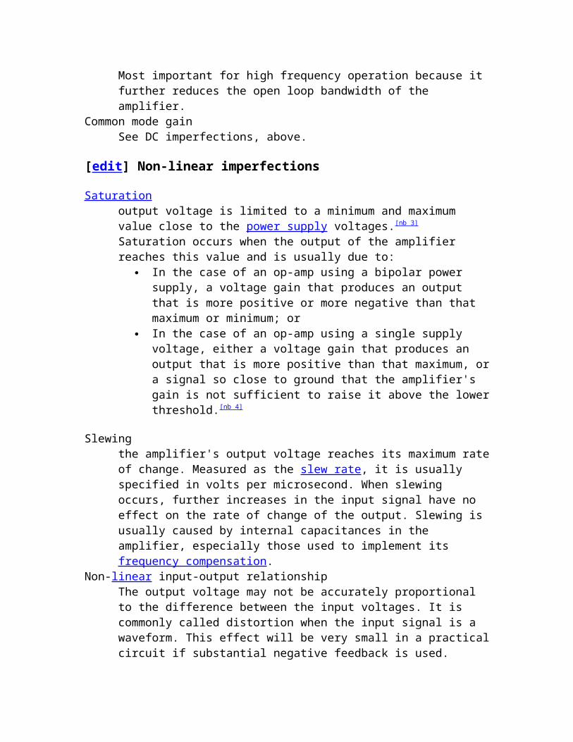
Saturationoutput voltage is limited to a minimum and maximum value close to the power supply voltages.[nb 3] Saturation occurs when the output of the amplifier reaches this value and is usually due to:
In the case of an op-amp using a bipolar power supply, a voltage gain that produces an output that is more positive or more negative than that maximum or minimum; or
In the case of an op-amp using a single supply voltage, either a voltage gain that produces an output that is more positive than that maximum, or a signal so close to ground that the amplifier's gain is not sufficient to raise it above the lower threshold.[nb 4]
Slewingthe amplifier's output voltage reaches its maximum rate of change. Measured as the slew rate, it is usually specified in volts per microsecond. When slewing occurs, further increases in the input signal have no effect on the rate of change of the output. Slewing is usually caused by internal capacitances in the amplifier, especially those used to implement its frequency compensation.
Non-linear input-output relationshipThe output voltage may not be accurately proportional to the difference between the input voltages. It is commonly called distortion when the input signal is a waveform. This effect will be very small in a practical circuit if substantial negative feedback is used.
[edit] Power considerations

Limited output currentThe output current must be finite. In practice, most op-amps are designed to limit the output current so as not to exceed a specified level — around 25 mA for a type 741 IC op-amp — thus protecting the op-amp and associated circuitry from damage. Modern designs are electronically more rugged than earlier implementations and some can sustain direct short circuits on their outputs without damage.
Limited dissipated powerThe output current flows through the op-amp's internal output impedance, dissipating heat. If the op-amp dissipates too much power, then its temperature will increase above some safe limit. The op-amp may enter thermal shutdown, or it may be destroyed.
Modern integrated FET or MOSFET op-amps approximate more closely the ideal op-amp than bipolar ICs when it comes to input impedance and input bias and offset currents. Bipolars are generally better when it comes to input voltage offset, and often have lower noise. Generally, at room temperature, with a fairly large signal, and limited bandwidth, FET and MOSFET op-amps now offer better performance.
[edit] Internal circuitry of 741 type op-amp
Though designs vary between products and manufacturers, all op-amps have basically the same internal structure, which consists of three stages:
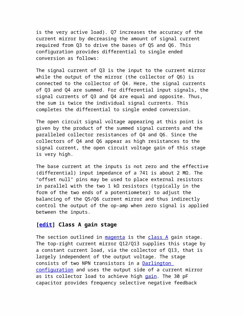
A component level diagram of the common 741 op-amp. Dotted lines outline: current mirrors (red); differential amplifier (blue); class A gain stage (magenta); voltage level shifter (green); output stage (cyan).

1. Differential amplifier – provides low noise amplification, high input impedance, usually a differential output.
2. Voltage amplifier – provides high voltage gain, a single-pole frequency roll-off, usually single-ended output.
3. Output amplifier – provides high current driving capability, low output impedance, current limiting and short circuit protection circuitry.
[edit] Input stage
[edit] Constant-current stabilization system
The input stage DC conditions are stabilized by a high-gain negative feedback system whose main parts are the two current mirrors on the left of the figure, outlined in red. The main purpose of this negative feedback system—to supply the differential input stage with a stable constant current—is realized as follows.
The current through the 39 kΩ resistor acts as a current reference for the other bias currents used in the chip. The voltage across the resistor is equal to the voltage across the supply rails ( ) minus two transistor diode drops (i.e., from Q11 and Q12),
and so the current has value . The Widlar current mirror built by Q10, Q11, and the 5 kΩ resistor produces a very small fraction of Iref at the Q10 collector. This small constant current through Q10's collector supplies the base currents for Q3 and Q4 as well as the Q9 collector current. The Q8/Q9 current mirror tries to make Q9's collector current the same as the Q3 and Q4 collector currents. Thus Q3 and Q4's combined base currents (which are of the same order as the overall chip's input currents) will be a small fraction of the already small Q10 current.
So, if the input stage current increases for any reason, the Q8/Q9 current mirror will draw current away from the bases of Q3 and Q4, which reduces the input stage current, and vice versa. The feedback loop also isolates the rest of the circuit from common-mode signals by making the base voltage of Q3/Q4 follow tightly 2Vbe below the higher of the two input voltages.
[edit] Differential amplifier
The blue outlined section is a differential amplifier. Q1 and Q2 are input emitter followers and together with the common base pair Q3 and Q4 form the differential input stage. In addition, Q3 and Q4 also act as level shifters and provide voltage gain to drive the class A amplifier. They also help to increase the reverse Vbe rating on the input transistors (the emitter-base junctions of the NPN transistors Q1 and Q2 break down at around 7 V but the PNP transistors Q3 and Q4 have breakdown voltages around 50 V).[9]
The differential amplifier formed by Q1–Q4 drives a current mirror active load formed by transistors Q5–Q7 (actually, Q6 is the very active load). Q7 increases the accuracy of the current mirror by decreasing the amount of signal current required from Q3 to drive

the bases of Q5 and Q6. This configuration provides differential to single ended conversion as follows:
The signal current of Q3 is the input to the current mirror while the output of the mirror (the collector of Q6) is connected to the collector of Q4. Here, the signal currents of Q3 and Q4 are summed. For differential input signals, the signal currents of Q3 and Q4 are equal and opposite. Thus, the sum is twice the individual signal currents. This completes the differential to single ended conversion.
The open circuit signal voltage appearing at this point is given by the product of the summed signal currents and the paralleled collector resistances of Q4 and Q6. Since the collectors of Q4 and Q6 appear as high resistances to the signal current, the open circuit voltage gain of this stage is very high.
The base current at the inputs is not zero and the effective (differential) input impedance of a 741 is about 2 MΩ. The "offset null" pins may be used to place external resistors in parallel with the two 1 kΩ resistors (typically in the form of the two ends of a potentiometer) to adjust the balancing of the Q5/Q6 current mirror and thus indirectly control the output of the op-amp when zero signal is applied between the inputs.
[edit] Class A gain stage
The section outlined in magenta is the class A gain stage. The top-right current mirror Q12/Q13 supplies this stage by a constant current load, via the collector of Q13, that is largely independent of the output voltage. The stage consists of two NPN transistors in a Darlington configuration and uses the output side of a current mirror as its collector load to achieve high gain. The 30 pF capacitor provides frequency selective negative feedback around the class A gain stage as a means of frequency compensation to stabilise the amplifier in feedback configurations. This technique is called Miller compensation and functions in a similar manner to an op-amp integrator circuit. It is also known as 'dominant pole compensation' because it introduces a dominant pole (one which masks the effects of other poles) into the open loop frequency response. This pole can be as low as 10 Hz in a 741 amplifier and it introduces a −3 dB loss into the open loop response at this frequency. This internal compensation is provided to achieve unconditional stability of the amplifier in negative feedback configurations where the feedback network is non-reactive and the closed loop gain is unity or higher. Hence, the use of the operational amplifier is simplified because no external compensation is required for unity gain stability; amplifiers without this internal compensation may require external compensation or closed loop gains significantly higher than unity.
[edit] Output bias circuitry
The green outlined section (based on Q16) is a voltage level shifter or rubber diode (i.e., a VBE multiplier); a type of voltage source. In the circuit as shown, Q16 provides a constant voltage drop between its collector and emitter regardless of the current through the circuit. If the base current to the transistor is assumed to be zero, and the voltage

between base and emitter (and across the 7.5 kΩ resistor) is 0.625 V (a typical value for a BJT in the active region), then the current through the 4.5 kΩ resistor will be the same as that through the 7.5 kΩ, and will produce a voltage of 0.375 V across it. This keeps the voltage across the transistor, and the two resistors at 0.625 + 0.375 = 1 V. This serves to bias the two output transistors slightly into conduction reducing crossover distortion. In some discrete component amplifiers this function is achieved with (usually two) silicon diodes.
[edit] Output stage
The output stage (outlined in cyan) is a Class AB push-pull emitter follower (Q14, Q20) amplifier with the bias set by the Vbe multiplier voltage source Q16 and its base resistors. This stage is effectively driven by the collectors of Q13 and Q19. Variations in the bias with temperature, or between parts with the same type number, are common so crossover distortion and quiescent current may be subject to significant variation. The output range of the amplifier is about one volt less than the supply voltage, owing in part to Vbe of the output transistors Q14 and Q20.
The 25 Ω resistor in the output stage acts as a current sense to provide the output current-limiting function which limits the current in the emitter follower Q14 to about 25 mA for the 741. Current limiting for the negative output is done by sensing the voltage across Q19's emitter resistor and using this to reduce the drive into Q15's base. Later versions of this amplifier schematic may show a slightly different method of output current limiting. The output resistance is not zero, as it would be in an ideal op-amp, but with negative feedback it approaches zero at low frequencies.
Note: while the 741 was historically used in audio and other sensitive equipment, such use is now rare because of the improved noise performance of more modern op-amps. Apart from generating noticeable hiss, 741s and other older op-amps may have poor common-mode rejection ratios and so will often introduce cable-borne mains hum and other common-mode interference, such as switch 'clicks', into sensitive equipment.
The "741" has come to often mean a generic op-amp IC (such as uA741, LM301, 558, LM324, TBA221 - or a more modern replacement such as the TL071). The description of the 741 output stage is qualitatively similar for many other designs (that may have quite different input stages), except:
Some devices (uA748, LM301, LM308) are not internally compensated (require an external capacitor from output to some point within the operational amplifier, if used in low closed-loop gain applications).
Some modern devices have rail-to-rail output capability (output can be taken to positive or negative power supply rail within a few millivolts).

Differential amplifierFrom Wikipedia, the free encyclopediaJump to: navigation, search
Differential amplifier symbolThe inverting and non-inverting inputs are distinguished by "−" and "+" symbols (respectively) placed in the amplifier triangle. Vs+ and Vs− are the power supply voltages; they are often omitted from the diagram for simplicity, but of course must be present in the actual circuit.
A differential amplifier is a type of electronic amplifier that multiplies the difference between two inputs by some constant factor (the differential gain).
Contents
[show]
[edit] Theory
Many electronic devices use differential amplifiers internally. The output of an ideal differential amplifier is given by:
Where and are the input voltages and Ad is the differential gain.In practice, however, the gain is not quite equal for the two inputs. This means, for
instance, that if and are equal, the output will not be zero, as it would be in the ideal case. A more realistic expression for the output of a differential amplifier thus includes a second term.

Ac is called the common-mode gain of the amplifier.As differential amplifiers are often used when it is desired to null out noise or bias-voltages that appear at both inputs, a low common-mode gain is usually considered good.
The common-mode rejection ratio, usually defined as the ratio between differential-mode gain and common-mode gain, indicates the ability of the amplifier to accurately cancel voltages that are common to both inputs. Common-mode rejection ratio (CMRR):
In a perfectly symmetrical differential amplifier, Ac is zero and the CMRR is infinite. Note that a differential amplifier is a more general form of amplifier than one with a single input; by grounding one input of a differential amplifier, a single-ended amplifier results. An operational amplifier, or op-amp, is a differential amplifier with very high differential-mode gain, very high input impedances, and a low output impedance. Some kinds of differential amplifier usually include several simpler differential amplifiers. For example, an instrumentation amplifier, a fully differential amplifier, an instrument amplifier, or an isolation amplifier are often built from several op-amps.
Differential amplifiers are found in many systems that utilise negative feedback, where one input is used for the input signal, the other for the feedback signal. A common application is for the control of motors or servos, as well as for signal amplification applications. In discrete electronics, a common arrangement for implementing a differential amplifier is the long-tailed pair, which is also usually found as the differential element in most op-amp integrated circuits. A differential amplifier is used as the input stage emitter coupled logic gates.
[edit] Examples
[edit] Long-tailed pair

Figure 2: A long-tailed pair with current-mirror load and constant-current biasing
A differential pair amplifier is formed from two transistors, or vacuum tubes (valves) – normally triodes, configured with emitters (for BJT transistors; cathodes for triodes, sources for FETs) connected together. A long-tailed pair (LTP), or emitter-coupled pair, is a differential pair where the shared emitter (or cathode or source) node is fed from something approximating a constant current source/sink, such as a relatively large value resistor to the negative supply (or positive for PNP or P-Channel devices) that develops a large voltage drop relative to the amplitude of the input signal... the "long tail". Therefore the summation of the two collector (or anode/plate or drain) currents is almost constant with signal.
The two bases (or grids or gates) can be fed with a differential (balanced) input signal and the two outputs from the collectors (etc.) remain balanced, or one input could be grounded to form a phase splitter circuit.
The higher the resistance of the current source Re, the lower Ac is, and the better the CMRR. In more sophisticated designs, a true (active) constant current source may be substituted for the long tail.
With two inputs and two outputs, this forms a differential amplifier stage. The two bases (or grids or gates) are inputs which are differentially amplified (subtracted and multiplied) by the pair; they can be fed with a differential (balanced) input signal, or one input could be grounded to form a phase splitter circuit. The output may be single-ended (taken from just one of the collectors (or anodes or drains)), or differential depending on the needs of the subsequent circuitry.
In a long-tailed pair formed using BJTs, the emitters are connected together, and then through the current source to ground or to a negative supply (for an LTP using NPN transistors). In this form, one of the transistors can be thought of as an amplifier operating in common emitter configuration, and the other as an emitter follower, feeding the other input signal into the emitter of the first stage. Since a transistor will amplify the current flowing between base and emitter, it follows that the current flowing in the collector circuit of the first transistor is proportional to the difference between the two inputs. However since the circuit is totally symmetrical, either element can be viewed as an

amplifier or as an emitter follower, understanding does not depend on which role you assign to which device.
The output from a differential amplifier is itself often differential. If this is not desired, then only one output can be used, disregarding the other output. Or to avoid sacrificing gain, a differential to single-ended converter can be utilized. This is often implemented as a current source.
Long-tailed pairs are frequently used in circuits that implement linear amplifiers with feedback, in operational amplifiers, and in other circuits that require a differential amplifier.
When used as a switch, the "left" base/grid is used as signal input and the "right" base/grid is grounded; output is taken from the right collector/plate. When the input is zero or negative, the output is close to zero; when the input is positive, the output is most-positive, dynamic operation being the same as the amplifier use described above.
Bias stability and independence from variations in device parameters can be improved by negative feedback introduced via cathode/emitter resistors.
[edit] Historical background
The long-tailed pair was originally a pair of vacuum tubes, about 20 years before transistors would be practically available. The circuit works the same way for all three-terminal devices with current gain.
The long-tailed pair circuit was designed and patented by Alan Blumlein in 1936 as an amplifier for small signals, and later applied to switching functions in radar and television. Today, its main feature is mostly vestigial, by virtue of the fact that long-tail resistor circuit bias points are largely determined by Ohm's Law and less so by active component characteristics.
The long-tailed pair was very successfully used in early British computing, most notably the Pilot ACE Model and descendants,[nb 1] Wilkes' EDSAC, and probably others designed by people who worked with Blumlein or his peers. The long-tailed pair has many attributes as a switch: largely immune to tube (transistor) variations (of great importance when machines contained 1,000 or more tubes), high gain, gain stability, high input impedance, medium/low output impedance, good clipper (with not-too-long tail), non-inverting (EDSAC contained no inverters!) and large output voltage swings. One disadvantage is that the output voltage swing (typically ±10–20 V) was imposed upon a high DC voltage (200 V or so), requiring care in signal coupling, usually some form of wide-band DC coupling. Many computers of this time tried to avoid this problem by using only AC-coupled pulse logic, which made them very large and overly complex (ENIAC: 18,000 tubes for a 20 digit calculator) or unreliable. DC-coupled circuitry became the norm after the first generation of vacuum tube computers.
Instrumentation amplifierFrom Wikipedia, the free encyclopediaJump to: navigation, search This page is about the electronic device.Amplifiers for musical instruments are instrument amplifiers.
Typical instrumentation amplifier schematic
An instrumentation (or instrumentational) amplifier is a type of differential amplifier that has been outfitted with input buffers, which eliminate the need for input impedance matching and thus make the amplifier particularly suitable for use in measurement and test equipment. Additional characteristics include very low DC offset, low drift, low noise, very high open-loop gain, very high common-mode rejection ratio, and very high input impedances. Instrumentation amplifiers are used where great accuracy and stability of the circuit both short- and long-term are required.
Although the instrumentation amplifier is usually shown schematically identical to a standard op-amp, the electronic instrumentation amp is almost always internally composed of 3 op-amps. These are arranged so that there is one op-amp to buffer each input (+,−), and one to produce the desired output with adequate impedance matching for the function.[1][2]
The most commonly used instrumentation amplifier circuit is shown in the figure. The gain of the circuit is

The rightmost amplifier, along with the resistors labelled R2 and R3 is just the standard differential amplifier circuit, with gain = R3 / R2 and differential input resistance = 2·R2. The two amplifiers on the left are the buffers. With Rgain removed (open circuited), they are simple unity gain buffers; the circuit will work in that state, with gain simply equal to R3 / R2 and high input impedance because of the buffers. The buffer gain could be increased by putting resistors between the buffer inverting inputs and ground to shunt away some of the negative feedback; however, the single resistor Rgain between the two inverting inputs is a much more elegant method: it increases the differential-mode gain of the buffer pair while leaving the common-mode gain equal to 1. This increases the common-mode rejection ratio (CMRR) of the circuit and also enables the buffers to handle much larger common-mode signals without clipping than would be the case if they were separate and had the same gain. Another benefit of the method is that it boosts the gain using a single resistor rather than a pair, thus avoiding a resistor-matching problem (although the two R1s need to be matched), and very conveniently allowing the gain of the circuit to be changed by changing the value of a single resistor. A set of switch-selectable resistors or even a potentiometer can be used for Rgain, providing easy changes to the gain of the circuit, without the complexity of having to switch matched pairs of resistors.
The ideal common-mode gain of an instrumentation amplifier is zero. In the circuit shown, common-mode gain is caused by mismatches in the values of the equally-numbered resistors and by the mis-match in common mode gains of the two input op-amps. Obtaining very closely matched resistors is a significant difficulty in fabricating these circuits, as is optimizing the common mode performance of the input op-amps.[3]
An instrumentation amp can also be built with 2 op-amps to save on cost and increase CMRR, but the gain must be higher than 2 (+6 dB).[4][5]
Instrumentation amplifiers can be built with individual op-amps and precision resistors, but are also available in integrated circuit form from several manufacturers (including Texas Instruments, National Semiconductor, Analog Devices, Linear Technology and Maxim Integrated Products). An IC instrumentation amplifier typically contains closely matched laser-trimmed resistors, and therefore offers excellent common-mode rejection. Examples include AD620, MAX4194, LT1167 and INA128.
Instrumentation Amplifiers can also be designed using "Indirect Current-feedback Architecture", which extend the operating range of these amplifiers to the negative power supply rail, and in some cases the positive power supply rail. This can be particularly useful in single-supply systems, where the negative power rail is simply the circuit ground (GND). Examples of parts utilizing this architecture are MAX4208/MAX4209 and AD8129/AD8130.
Feedback-free instrumentation amplifier is the high input impedance differential amplifier designed without the external feedback network. This allows reduction in the number of amplifiers (one instead of three), reduced noise (no thermal noise is brought

on by the feedback resistors) and increased bandwidth (no frequency compensation is needed). The design of such amplifiers is treated here.
Chopper stabilized (or zero drift) instrumentation amplifiers such as the LTC2053 use a switching input front end to eliminate DC offset errors and drift.
Active filterFrom Wikipedia, the free encyclopediaJump to: navigation, search
An example of high-pass active filter of the Sallen Key topology. The operational amplifier, U1, is used as a buffer amplifier.
An active filter is a type of analog electronic filter, distinguished by the use of one or more active components i.e. voltage amplifiers or buffer amplifiers. Typically this will be a vacuum tube, or solid-state (transistor or operational amplifier).
Active filters have three main advantages over passive filters:
Inductors can be avoided. Passive filters without inductors cannot obtain a high Q (low damping), but with them are often large and expensive (at low frequencies), may have significant internal resistance, and may pick up surrounding electromagnetic signals.
The shape of the response, the Q (Quality factor), and the tuned frequency can often be set easily by varying resistors, in some filters one parameter can be adjusted without affecting the others. Variable inductances for low frequency filters are not practical.
The amplifier powering the filter can be used to buffer the filter from the electronic components it drives or is fed from, variations in which could otherwise significantly affect the shape of the frequency response.

Active filter circuit configurations (electronic filter topology) include:
Sallen and Key, and VCVS filters (low dependency on accuracy of the components)
State variable and biquadratic filters Twin T filter (fully passive) Dual Amplifier Bandpass (DABP) Wien notch Multiple Feedback Filter Fliege (lowest component count for 2 opamp but with good controllability over
frequency and type) Akerberg Mossberg (one of the topologies that offer complete and independent
control over gain, frequency, and type)
All the varieties of passive filters can also be found in active filters. Some of them are:
High-pass filters – attenuation of frequencies below their cut-off points. Low-pass filters – attenuation of frequencies above their cut-off points. Band-pass filters – attenuation of frequencies both above and below those they
allow to pass. Notch filters – attenuation of certain frequencies while allowing all others to pass.
Combinations are possible, such as notch and high-pass (for example, in a rumble filter where most of the offending rumble comes from a particular frequency), e.g.Elliptic filters.
[edit] Design of active filters
To design filters, the specifications that need to be established include:
The range of desired frequencies (the passband) together with the shape of the frequency response. This indicates the variety of filter (see above) and the center or corner frequencies.
Input and output impedance requirements. These limit the circuit topologies available; for example, most, but not all active filter topologies provide a buffered (low impedance) output. However, remember that the internal output impedance of operational amplifiers, if used, may rise markedly at high frequencies and reduce the attenuation from that expected. Be aware that some high-pass filter topologies present the input with almost a short circuit to high frequencies.
The degree to which unwanted signals should be rejected. o In the case of narrow-band bandpass filters, the Q determines the -3dB
bandwidth but also the degree of rejection of frequencies far removed from the center frequency; if these two requirements are in conflict then a staggered-tuning bandpass filter may be needed.
o For notch filters, the degree to which unwanted signals at the notch frequency must be rejected determines the accuracy of the components,
but not the Q, which is governed by desired steepness of the notch, i.e. the bandwidth around the notch before attenuation becomes small.
o For high-pass and low-pass (as well as band-pass filters far from the center frequency), the required rejection may determine the slope of attenuation needed, and thus the "order" of the filter. A second-order all-pole filter gives an ultimate slope of about 12 dB per octave (40dB/decade), but the slope close to the corner frequency is much less, sometimes necessitating a notch be added to the filter.
The allowable "ripple" (variation from a flat response, in decibels) within the passband of high-pass and low-pass filters, along with the shape of the frequency response curve near the corner frequency, determine the damping factor (reciprocal of Q). This also affects the phase response, and the time response to a square-wave input. Several important response shapes (damping factors) have well-known names:
o Chebyshev filter – slight peaking/ripple in the passband before the corner; Q>0.7071 for 2nd-order filters
o Butterworth filter – flattest amplitude response; Q=0.7071 for 2nd-order filters
o Linkwitz–Riley filter – desirable properties for audio crossover applications; Q = 0.5 (critically damped)
o Paynter or transitional Thompson-Butterworth or "compromise" filter – faster fall-off than Bessel; Q=0.639 for 2nd-order filters
o Bessel filter – best time-delay, best overshoot response; Q=0.577 for 2nd-order filters
o Elliptic filter or Cauer filters – add a notch (or "zero") just outside the passband, to give a much greater slope in this region than the combination of order and damping factor without the notch.