52194830 telys 2 user manual pro
TRANSCRIPT
User's guide
SSDDMMOO
CCoonnttrrooll uunniitt
TTEELLYYSS
V 6.1.0 (16/11/2006) 33502019901_0_1

33502019901_0_1 1/88
1. Introduction to TELYS ......................................................................................................................................................................... 2
1.1. Introduction ............................................................................................................................................................................. 2 1.2. Operating conditions ............................................................................................................................................................... 2 1.3. Conformity to legal and regulatory requirements.................................................................................................................... 3
2. Description............................................................................................................................................................................................ 4 2.1. Standard configuration ............................................................................................................................................................ 4
2.1.1 View of the front panel............................................................................................................................................................ 5 2.1.2 View of the rear panel ............................................................................................................................................................. 7 2.1.3 Description of the screen......................................................................................................................................................... 9 2.1.4 Description of the pictograms in zone 1................................................................................................................................ 10 2.1.5 Description of the pictograms in zone 2................................................................................................................................ 11 2.1.6 Description of the pictograms in zone 3................................................................................................................................ 12 2.1.7 Display of messages in zone 4 .............................................................................................................................................. 14
2.2. Options .................................................................................................................................................................................. 18 3. Introduction to menus ......................................................................................................................................................................... 20
3.1. "Actions" menu ..................................................................................................................................................................... 24 3.2. "Information" menu............................................................................................................................................................... 26 3.3. "Settings" menu..................................................................................................................................................................... 28
3.3.1 Communication ..................................................................................................................................................................... 29 3.3.2 Changing the frequency ........................................................................................................................................................ 30 3.3.3 Changing the voltage............................................................................................................................................................. 30 3.3.4 Parameter settings ................................................................................................................................................................. 31 3.3.5 Installer access ...................................................................................................................................................................... 35
3.4. "Country" menu..................................................................................................................................................................... 35 4. Alarms and faults ................................................................................................................................................................................ 36
4.1. Viewing alarms and faults ..................................................................................................................................................... 36 4.2. Activation of an alarm or fault .............................................................................................................................................. 37 4.3. Activation of an alarm and a fault ......................................................................................................................................... 38 4.4. Engine fault codes display..................................................................................................................................................... 39 4.5. Horn reset .............................................................................................................................................................................. 40
5. Access levels....................................................................................................................................................................................... 41 5.1. List of access levels ............................................................................................................................................................... 41 5.2. Contents of access level 0...................................................................................................................................................... 41 5.3. Contents of access level 1...................................................................................................................................................... 42
6. Exterior communication...................................................................................................................................................................... 43 6.1. Series communication with the RS485 port .......................................................................................................................... 43 6.2. Communication using USB ports .......................................................................................................................................... 43
6.2.1 USB communication - operation........................................................................................................................................... 45 6.2.2 HOST USB port .................................................................................................................................................................... 45 6.2.3 DEVICE USB port ................................................................................................................................................................ 47
7. Use ...................................................................................................................................................................................................... 47 7.1. Manual mode......................................................................................................................................................................... 47
7.1.1 Generating set start-up .......................................................................................................................................................... 47 7.1.2 Under load tests..................................................................................................................................................................... 48 7.1.3 Stopping the generating set ................................................................................................................................................... 49
7.2. Automatic mode .................................................................................................................................................................... 50 7.2.1 Generating set start-up .......................................................................................................................................................... 50 7.2.2 Applying the load.................................................................................................................................................................. 52 7.2.3 Stopping the generating set ................................................................................................................................................... 52
8. Fault finding........................................................................................................................................................................................ 53 9. Maintenance........................................................................................................................................................................................ 53
9.1. Replacing the fuse ................................................................................................................................................................. 53 10. Appendix........................................................................................................................................................................................... 54
10.1. Enclosure A - List of John Deere - Volvo and Perkins fault codes ....................................................................................... 54 10.2. Enclosure B - List of MTU engine fault codes...................................................................................................................... 68 10.3. Enclosure C - List and explanation of parameters ................................................................................................................. 86 10.4. Enclosure D - Glossary.......................................................................................................................................................... 88
33502019901_0_1 2/88
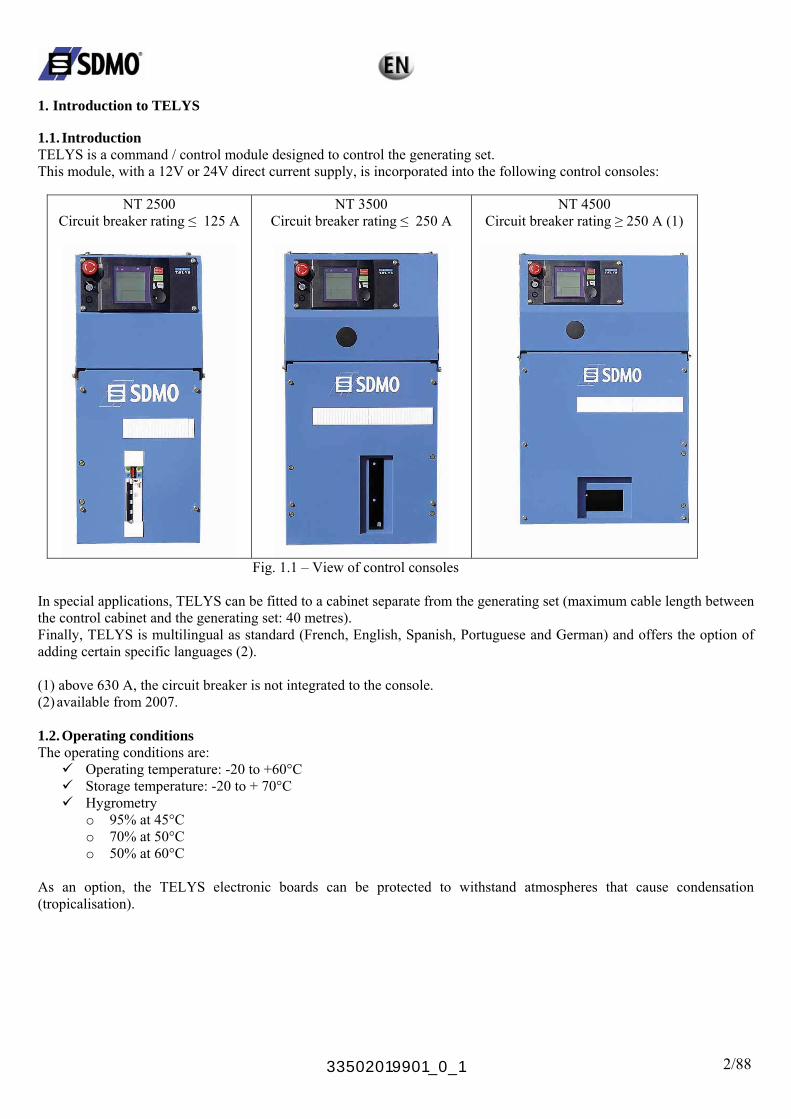
1. Introduction to TELYS 1.1. Introduction TELYS is a command / control module designed to control the generating set. This module, with a 12V or 24V direct current supply, is incorporated into the following control consoles:
NT 2500 Circuit breaker rating ≤ 125 A
NT 3500 Circuit breaker rating ≤ 250 A
NT 4500 Circuit breaker rating ≥ 250 A (1)
Fig. 1.1 – View of control consoles In special applications, TELYS can be fitted to a cabinet separate from the generating set (maximum cable length between the control cabinet and the generating set: 40 metres). Finally, TELYS is multilingual as standard (French, English, Spanish, Portuguese and German) and offers the option of adding certain specific languages (2). (1) above 630 A, the circuit breaker is not integrated to the console. (2) available from 2007. 1.2. Operating conditions The operating conditions are:
Operating temperature: -20 to +60°C Storage temperature: -20 to + 70°C Hygrometry
o 95% at 45°C o 70% at 50°C o 50% at 60°C
As an option, the TELYS electronic boards can be protected to withstand atmospheres that cause condensation (tropicalisation).
33502019901_0_1 3/88
1.3. Conformity to legal and regulatory requirements The TELYS machine conforms to the standards below: Conforms with European or international directives and standards:
EMC general standards EN 61000-6-2 and EN 61000-6-4 (emission and protection) LOW VOLTAGE standards Salt spray test performance: In accordance with standard EN68011-2-11 Protection index of a TELYS mounted to a console: IP31 with the soft USB port protective cover fitted
(according to EN 60529) Note: European Parliament directives relating to Electrical and Electronic Equipment (WEEE):
- Limitation of Harmful substances in Electrical and Electronic Equipment (LSDEEE or RoHS) (Directive 2002/95/CE dated January 27th 2003)
- Waste electrical and electronic equipment (WEEE). (Directive 2002/96/CE dated January 27th 2003) Generating sets and their components do not come under the field of application of these two directives.

33502019901_0_1 4/88
2. Description 2.1. Standard configuration The TELYS module is composed of a polycarbonate cover plate, a screen, signalling LEDs, control components and electronic boards. The functional connections are as follows:
Network Voltage Monitoring Relay
Speed – Voltage Trimming Board (in 2007)
Engine
Alternator
Input/Output Board
Voltage/Current Measurements
Motorised circuit breaker or
Normal/Emergency switch

2.1.1 View of the front panel
33502019901_0_1 5/88
Fig. 2.1 – View of the front side 1 Emergency stop button for switching off the generating set in the event of a fault which could endanger personnel
or damage equipment 2 Key switch for starting up/shutting down the module 3 Electronic board protection fuse 4 Scrolling and selection wheel for scrolling through screens and selecting items simply by pressing the wheel 5 STOP button, press to switch the generating set off 6 START button, press to switch the generating set on 7 Power ON LEDs and fault warning LEDs 8 Location of USB ports 9 Mounting bolt. 10 LCD for displaying alarms and faults, operating status, electrical and mechanical quantities. 11 ESC button: return to the previous selection and fault RESET function 12 MENU button to access the menus 13 Lighting for emergency stop button
2
1
3
5
9613 9 7
12
9 8 10 11 4 9
33502019901_0_1 6/88
1 2 3
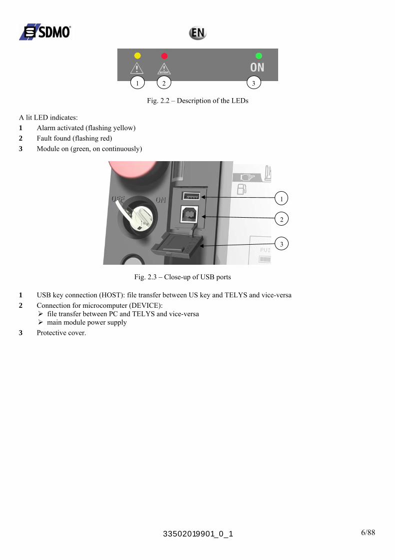
Fig. 2.2 – Description of the LEDs
A lit LED indicates: 1 Alarm activated (flashing yellow) 2 Fault found (flashing red) 3 Module on (green, on continuously)
Fig. 2.3 – Close-up of USB ports
2
3
1
1 USB key connection (HOST): file transfer between US key and TELYS and vice-versa 2 Connection for microcomputer (DEVICE):
file transfer between PC and TELYS and vice-versa main module power supply
3 Protective cover.

33502019901_0_1 7/88
2.1.2 View of the rear panel
J28 USB Host 2 J30 Ethernet Port J31 RS 485 port
J26 Engine CAN Bus J29 Module CAN Bus
Fig. 2.4 – View of the rear side
J3M J25 J17 J16 J18 J33B J27 Customer connection area
J1M
J1
J24 J20 J23 J14 J15 J5 J21
Battery backup (clock) End of line resistor
33502019901_0_1 8/88
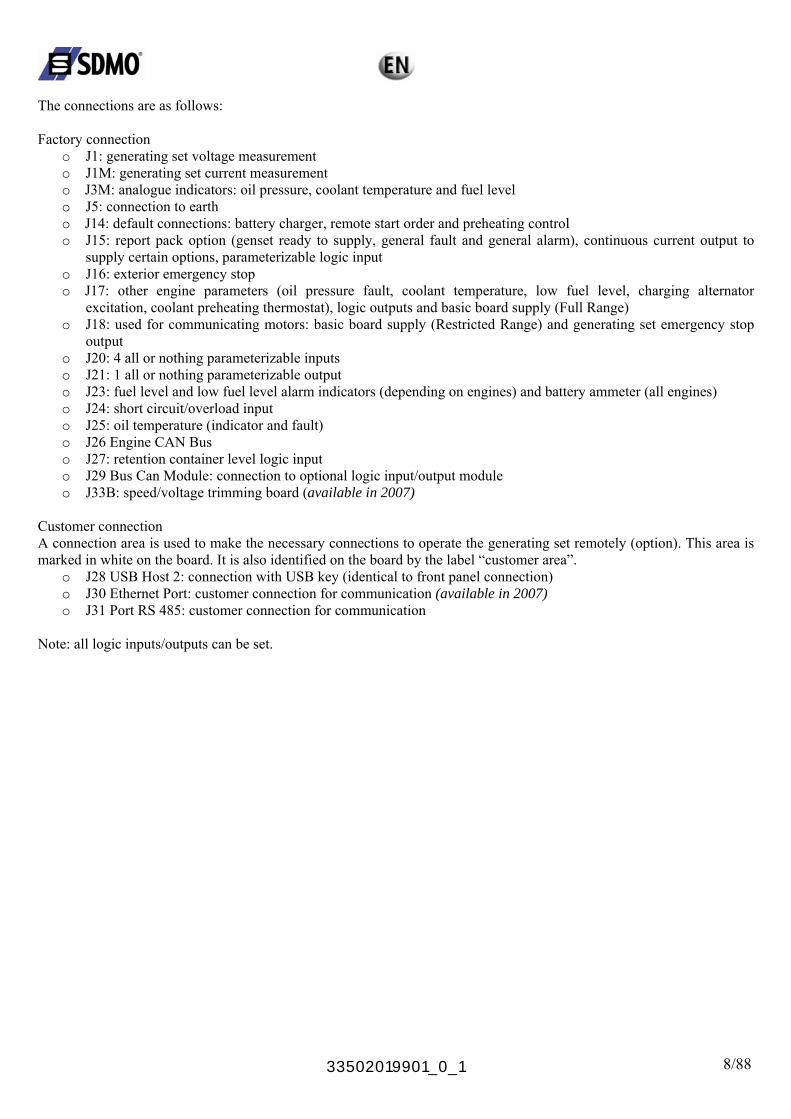
The connections are as follows: Factory connection
o J1: generating set voltage measurement o J1M: generating set current measurement o J3M: analogue indicators: oil pressure, coolant temperature and fuel level o J5: connection to earth o J14: default connections: battery charger, remote start order and preheating control o J15: report pack option (genset ready to supply, general fault and general alarm), continuous current output to
supply certain options, parameterizable logic input o J16: exterior emergency stop o J17: other engine parameters (oil pressure fault, coolant temperature, low fuel level, charging alternator
excitation, coolant preheating thermostat), logic outputs and basic board supply (Full Range) o J18: used for communicating motors: basic board supply (Restricted Range) and generating set emergency stop
output o J20: 4 all or nothing parameterizable inputs o J21: 1 all or nothing parameterizable output o J23: fuel level and low fuel level alarm indicators (depending on engines) and battery ammeter (all engines) o J24: short circuit/overload input o J25: oil temperature (indicator and fault) o J26 Engine CAN Bus o J27: retention container level logic input o J29 Bus Can Module: connection to optional logic input/output module o J33B: speed/voltage trimming board (available in 2007)
Customer connection A connection area is used to make the necessary connections to operate the generating set remotely (option). This area is marked in white on the board. It is also identified on the board by the label “customer area”.
o J28 USB Host 2: connection with USB key (identical to front panel connection) o J30 Ethernet Port: customer connection for communication (available in 2007) o J31 Port RS 485: customer connection for communication
Note: all logic inputs/outputs can be set.
33502019901_0_1 9/88
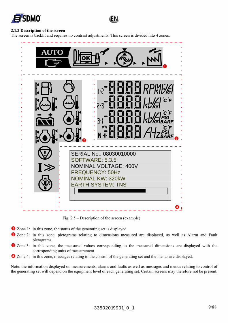
2.1.3 Description of the screen The screen is backlit and requires no contrast adjustments. This screen is divided into 4 zones.
SERIAL No.: 08030010000 SOFTWARE: 5.3.5 NOMINAL VOLTAGE: 400V FREQUENCY: 50Hz NOMINAL KW: 320kW EARTH SYSTEM: TNS
Fig. 2.5 – Description of the screen (example)
Zone 1: in this zone, the status of the generating set is displayed
Zone 2: in this zone, pictograms relating to dimensions measured are displayed, as well as Alarm and Fault pictograms
Zone 3: in this zone, the measured values corresponding to the measured dimensions are displayed with the corresponding units of measurement
Zone 4: in this zone, messages relating to the control of the generating set and the menus are displayed. Note: the information displayed on measurements, alarms and faults as well as messages and menus relating to control of the generating set will depend on the equipment level of each generating set. Certain screens may therefore not be present.
33502019901_0_1 10/88
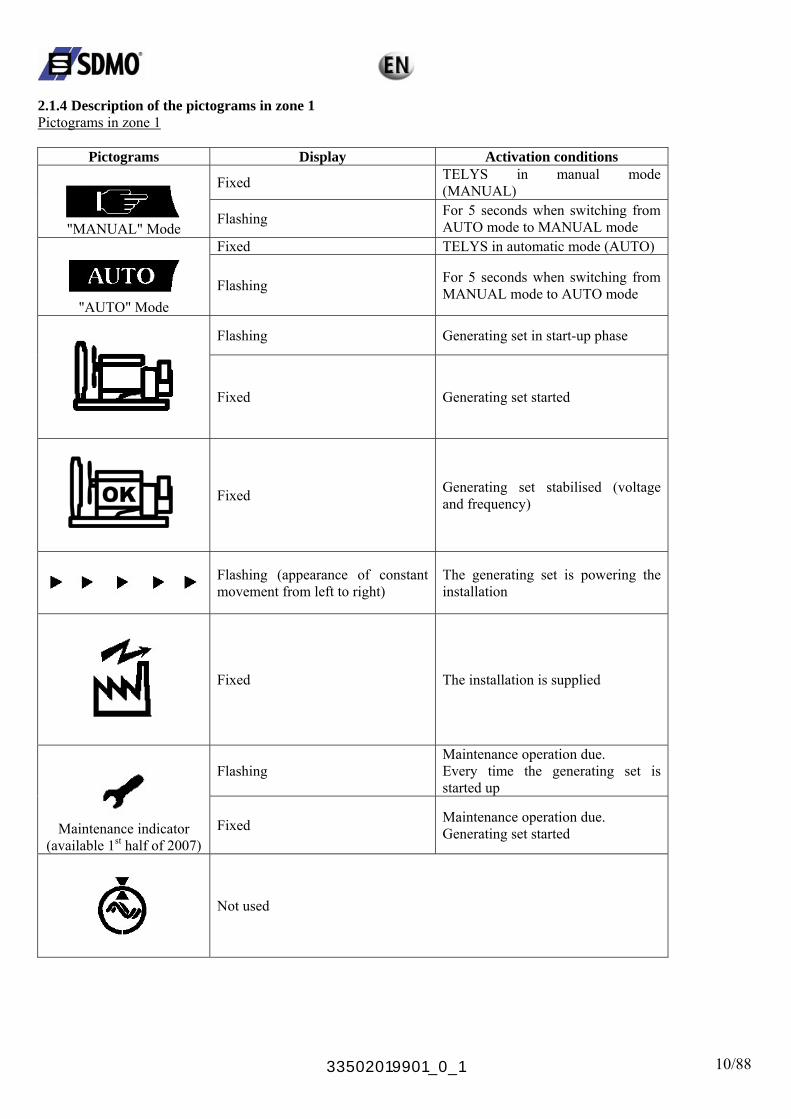
2.1.4 Description of the pictograms in zone 1 Pictograms in zone 1
Pictograms Display Activation conditions
Fixed TELYS in manual mode (MANUAL)
"MANUAL" Mode
Flashing For 5 seconds when switching from AUTO mode to MANUAL mode
Fixed TELYS in automatic mode (AUTO)
"AUTO" Mode
Flashing For 5 seconds when switching from MANUAL mode to AUTO mode
Flashing Generating set in start-up phase
Fixed Generating set started
Fixed Generating set stabilised (voltage and frequency)
Flashing (appearance of constant movement from left to right)
The generating set is powering the installation
Fixed The installation is supplied
Flashing Maintenance operation due. Every time the generating set is started up
Maintenance indicator
(available 1st half of 2007) Fixed Maintenance operation due.
Generating set started
Not used
33502019901_0_1 11/88
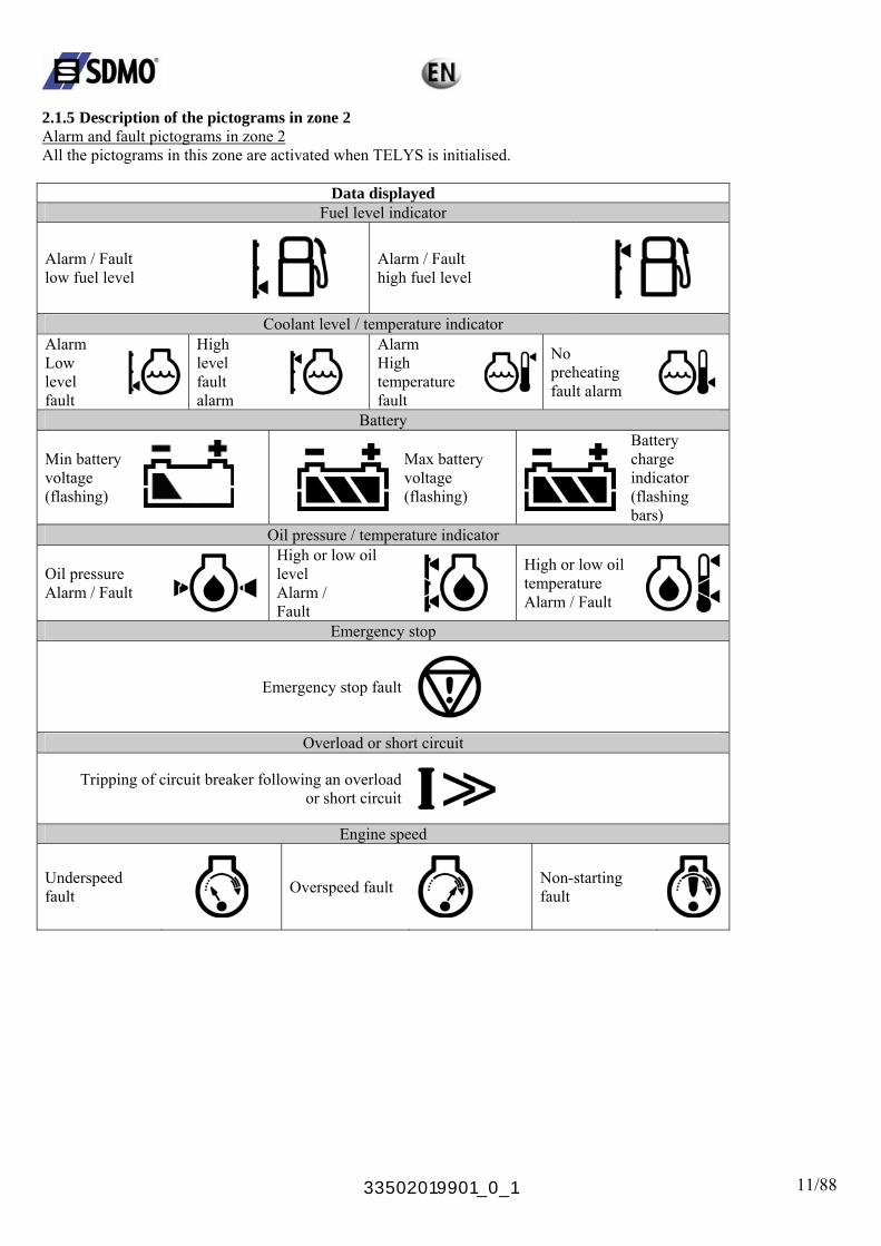
2.1.5 Description of the pictograms in zone 2 Alarm and fault pictograms in zone 2 All the pictograms in this zone are activated when TELYS is initialised.
Data displayed Fuel level indicator
Alarm / Fault low fuel level
Alarm / Fault high fuel level
Coolant level / temperature indicator Alarm High
level fault alarm
Low level fault
Alarm High temperature fault
No preheating fault alarm
Battery
Min battery voltage (flashing)
Max battery voltage (flashing)
Battery charge indicator (flashing bars)
Oil pressure / temperature indicator
Oil pressure Alarm / Fault
High or low oil level
Alarm / Fault
High or low oil temperature Alarm / Fault
Emergency stop
Emergency stop fault
Overload or short circuit
Tripping of circuit breaker following an overloador short circuit
Engine speed
Underspeed fault
Overspeed fault Non-starting
fault
33502019901_0_1 12/88
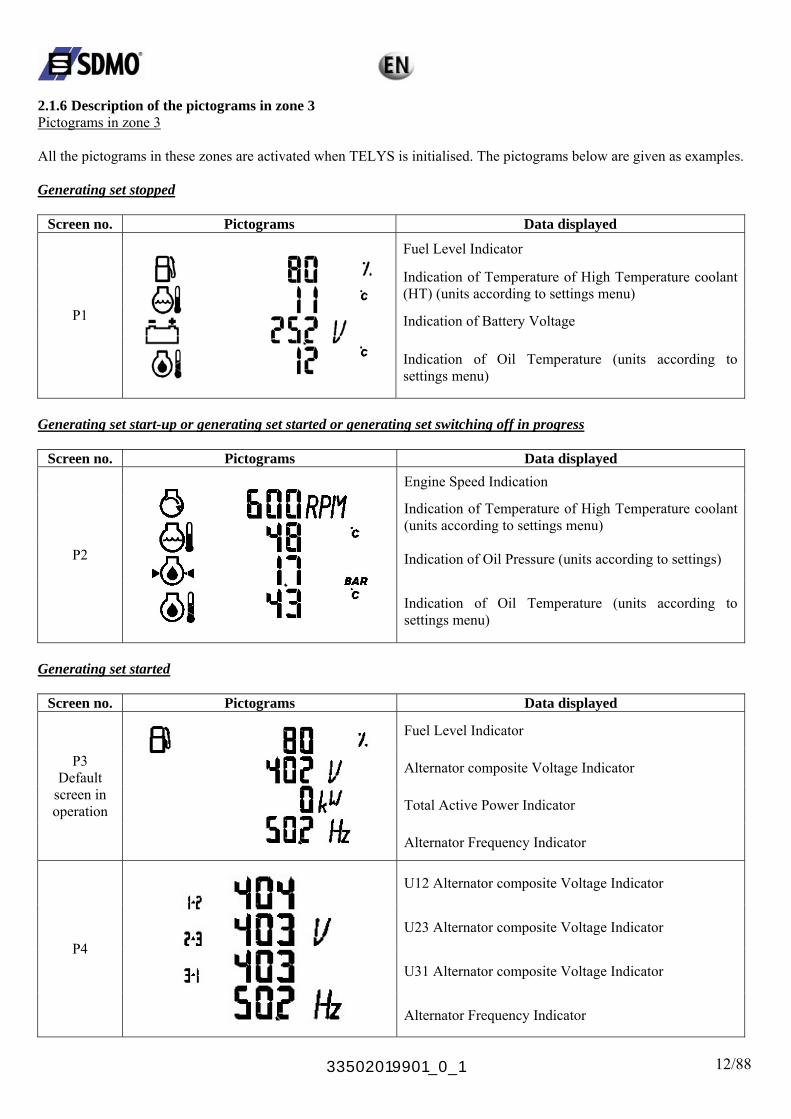
2.1.6 Description of the pictograms in zone 3 Pictograms in zone 3 All the pictograms in these zones are activated when TELYS is initialised. The pictograms below are given as examples. Generating set stopped
Screen no. Pictograms Data displayed
Fuel Level Indicator
Indication of Temperature of High Temperature coolant (HT) (units according to settings menu)
Indication of Battery Voltage P1
Indication of Oil Temperature (units according to settings menu)
Generating set start-up or generating set started or generating set switching off in progress
Screen no. Pictograms Data displayed Engine Speed Indication
Indication of Temperature of High Temperature coolant (units according to settings menu)
Indication of Oil Pressure (units according to settings) P2
Indication of Oil Temperature (units according to settings menu)
Generating set started
Screen no. Pictograms Data displayed
Fuel Level Indicator
Alternator composite Voltage Indicator
Total Active Power Indicator
P3 Default
screen in operation
Alternator Frequency Indicator
U12 Alternator composite Voltage Indicator
U23 Alternator composite Voltage Indicator
U31 Alternator composite Voltage Indicator P4
Alternator Frequency Indicator
33502019901_0_1 13/88
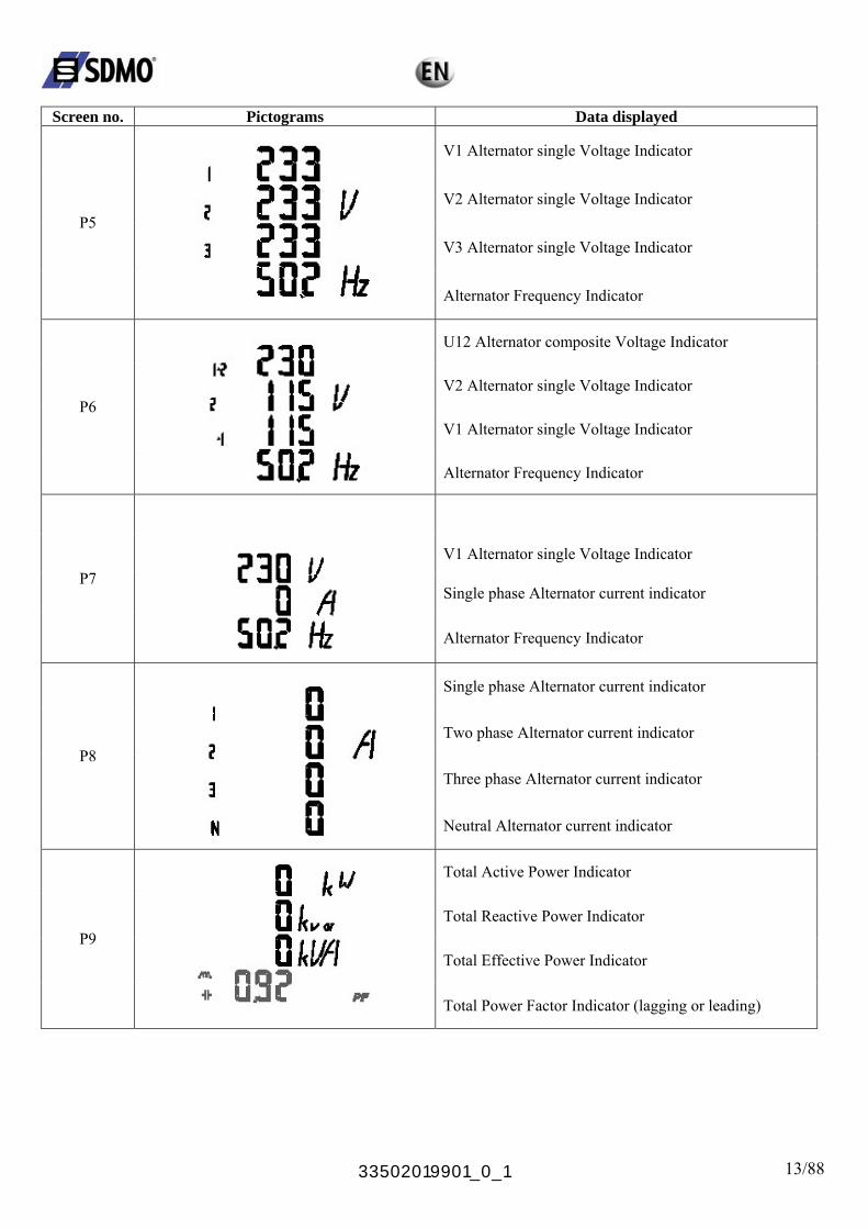
Screen no. Pictograms Data displayed
V1 Alternator single Voltage Indicator
V2 Alternator single Voltage Indicator
V3 Alternator single Voltage Indicator P5
Alternator Frequency Indicator
U12 Alternator composite Voltage Indicator
V2 Alternator single Voltage Indicator
V1 Alternator single Voltage Indicator P6
Alternator Frequency Indicator
V1 Alternator single Voltage Indicator
Single phase Alternator current indicator P7
Alternator Frequency Indicator
Single phase Alternator current indicator
Two phase Alternator current indicator
Three phase Alternator current indicator P8
Neutral Alternator current indicator
Total Active Power Indicator
Total Reactive Power Indicator
Total Effective Power Indicator P9
Total Power Factor Indicator (lagging or leading)
33502019901_0_1 14/88
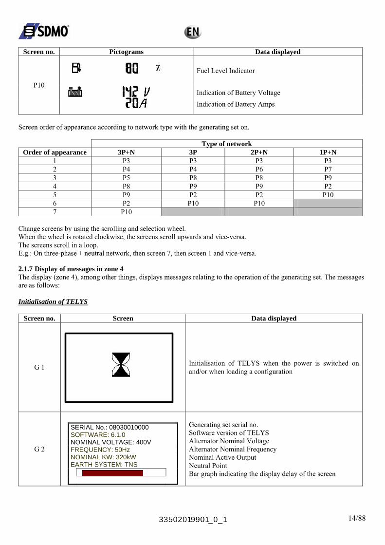
Screen no. Pictograms Data displayed
Fuel Level Indicator
Indication of Battery Voltage P10
Indication of Battery Amps
Screen order of appearance according to network type with the generating set on.
Type of network Order of appearance 3P+N 3P 2P+N 1P+N
1 P3 P3 P3 P3 2 P4 P4 P6 P7 3 P5 P8 P8 P9 4 P8 P9 P9 P2 5 P9 P2 P2 P10 6 P2 P10 P10 7 P10
Change screens by using the scrolling and selection wheel. When the wheel is rotated clockwise, the screens scroll upwards and vice-versa. The screens scroll in a loop. E.g.: On three-phase + neutral network, then screen 7, then screen 1 and vice-versa. 2.1.7 Display of messages in zone 4 The display (zone 4), among other things, displays messages relating to the operation of the generating set. The messages are as follows: Initialisation of TELYS
Screen no. Screen Data displayed
G 1
Initialisation of TELYS when the power is switched on and/or when loading a configuration
G 2
SERIAL No.: 08030010000 SOFTWARE: 6.1.0 NOMINAL VOLTAGE: 400V FREQUENCY: 50Hz NOMINAL KW: 320kW EARTH SYSTEM: TNS
Generating set serial no. Software version of TELYS Alternator Nominal Voltage Alternator Nominal Frequency Nominal Active Output Neutral Point Bar graph indicating the display delay of the screen
33502019901_0_1 15/88
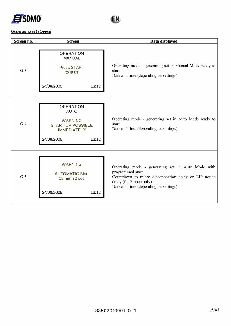
Generating set stopped
Screen no. Screen Data displayed
G 3
OPERATION MANUAL
Press START
to start 24/08/2005 13:12
Operating mode - generating set in Manual Mode ready to start Date and time (depending on settings)
G 4
OPERATION AUTO
WARNING
START-UP POSSIBLE IMMEDIATELY
24/08/2005 13:12
Operating mode - generating set in Auto Mode ready to start Date and time (depending on settings)
G 5
WARNING
AUTOMATIC Start
19 min 30 sec 24/08/2005 13:12
Operating mode - generating set in Auto Mode with programmed start Countdown to micro disconnection delay or EJP notice delay (for France only)
Date and time (depending on settings)
33502019901_0_1 16/88
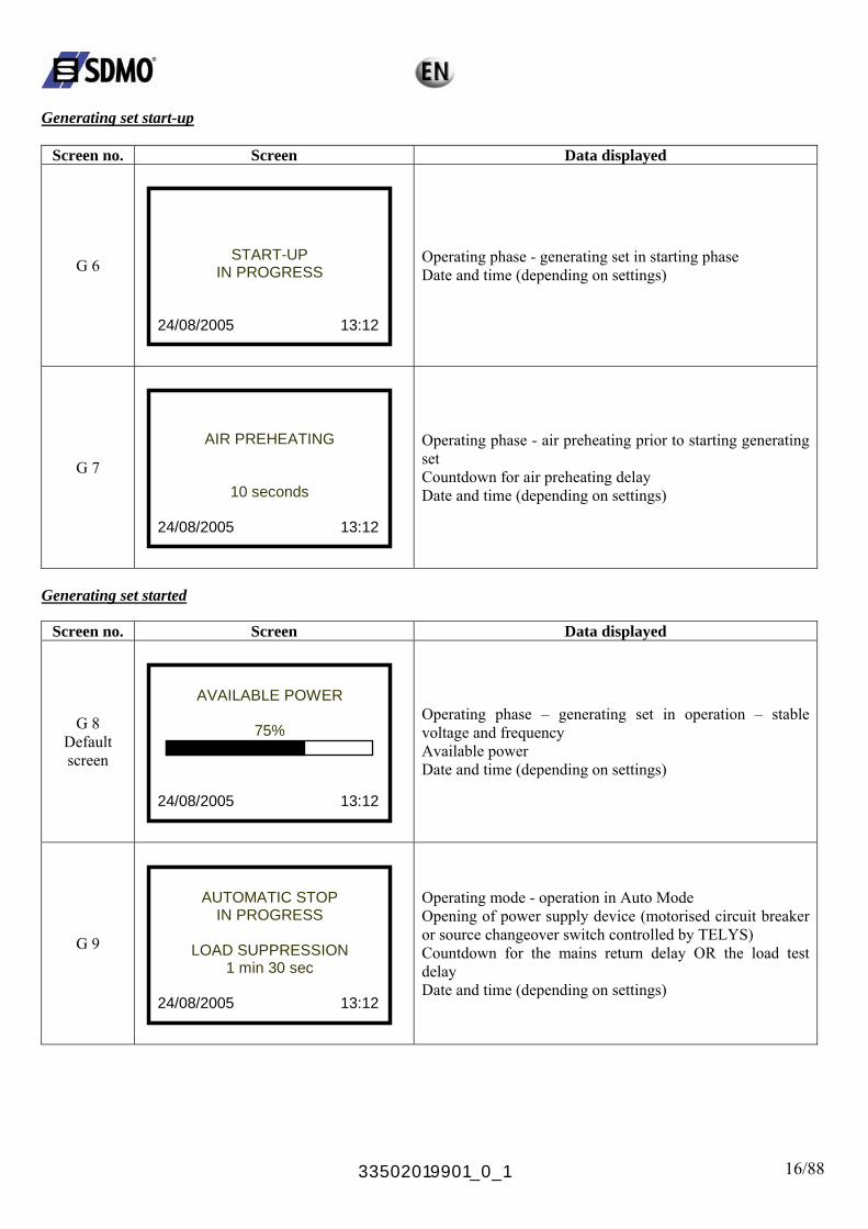
Generating set start-up
Screen no. Screen Data displayed
G 6
START-UP IN PROGRESS
24/08/2005 13:12
Operating phase - generating set in starting phase Date and time (depending on settings)
G 7
AIR PREHEATING
10 seconds
24/08/2005 13:12
Operating phase - air preheating prior to starting generating set Countdown for air preheating delay Date and time (depending on settings)
Generating set started
Screen no. Screen Data displayed
G 8 Default screen
AVAILABLE POWER
75%
24/08/2005 13:12
Operating phase – generating set in operation – stable voltage and frequency
Available power Date and time (depending on settings)
G 9
AUTOMATIC STOP
IN PROGRESS
LOAD SUPPRESSION 1 min 30 sec
24/08/2005 13:12
Operating mode - operation in Auto Mode Opening of power supply device (motorised circuit breaker or source changeover switch controlled by TELYS) Countdown for the mains return delay OR the load test delay Date and time (depending on settings)
33502019901_0_1 17/88
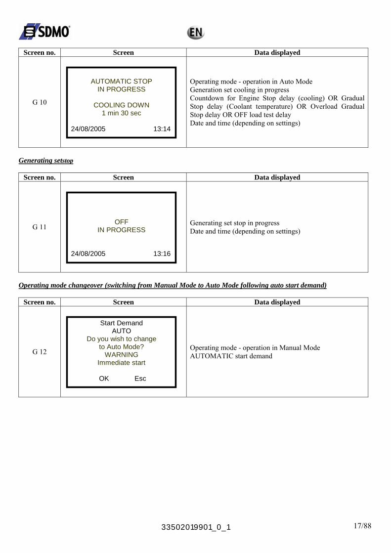
Screen no. Screen Data displayed
G 10
AUTOMATIC STOP
IN PROGRESS
COOLING DOWN 1 min 30 sec
24/08/2005 13:14
Operating mode - operation in Auto Mode Generation set cooling in progress Countdown for Engine Stop delay (cooling) OR Gradual Stop delay (Coolant temperature) OR Overload Gradual Stop delay OR OFF load test delay Date and time (depending on settings)
Generating setstop
Screen no. Screen Data displayed
G 11
OFF IN PROGRESS
24/08/2005 13:16
Generating set stop in progress Date and time (depending on settings)
Operating mode changeover (switching from Manual Mode to Auto Mode following auto start demand)
Screen no. Screen Data displayed
G 12
Start Demand AUTO
Do you wish to change to Auto Mode?
WARNING Immediate start
OK Esc
Operating mode - operation in Manual Mode
AUTOMATIC start demand

33502019901_0_1 18/88
Generating set stop request due to fault or by pressing STOP in Auto Mode
Screen no. Screen Data displayed
G 13
Manual Mode activated
Do you wish to change
to AUTO mode?
Warning message for switching to Manual Mode after the STOP button has been pressed or a fault has appeared
OK Esc
Operating mode - operation in Auto Mode (generating set in operation)
2.2. Options The presence of optional boards indicated on the electrical diagram depends on the options fitted to the generating set. In order to have additional inputs and outputs, TELYS can be fitted with five logic input/output boards. The input/output board holds additional logic inputs and outputs (all or nothing), which can be used if those of the basic module are not sufficient. These inputs can be used to detect additional alarms or faults and outputs can be used for data transfers or to control options.
33502019901_0_1 19/88
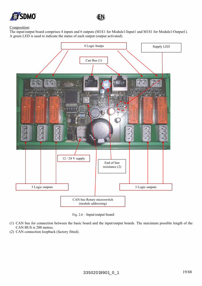
Composition: The input/output board comprises 4 inputs and 6 outputs (M1E1 for Module1/Input1 and M1S1 for Module1/Output1). A green LED is used to indicate the status of each output (output activated).
4 Logic Inutps
Can Bus (1)
12 / 24 V supply
3 Logic outputs
CAN bus Rotary microswitch (module addressing)
End of line resistance (2)
3 Logic outputs
Supply LED
Fig. 2.6 – Input/output board
(1) CAN bus for connection between the basic board and the input/output boards. The maximum possible length of the
CAN BUS is 200 metres. (2) CAN connection loopback (factory fitted).
33502019901_0_1 20/88
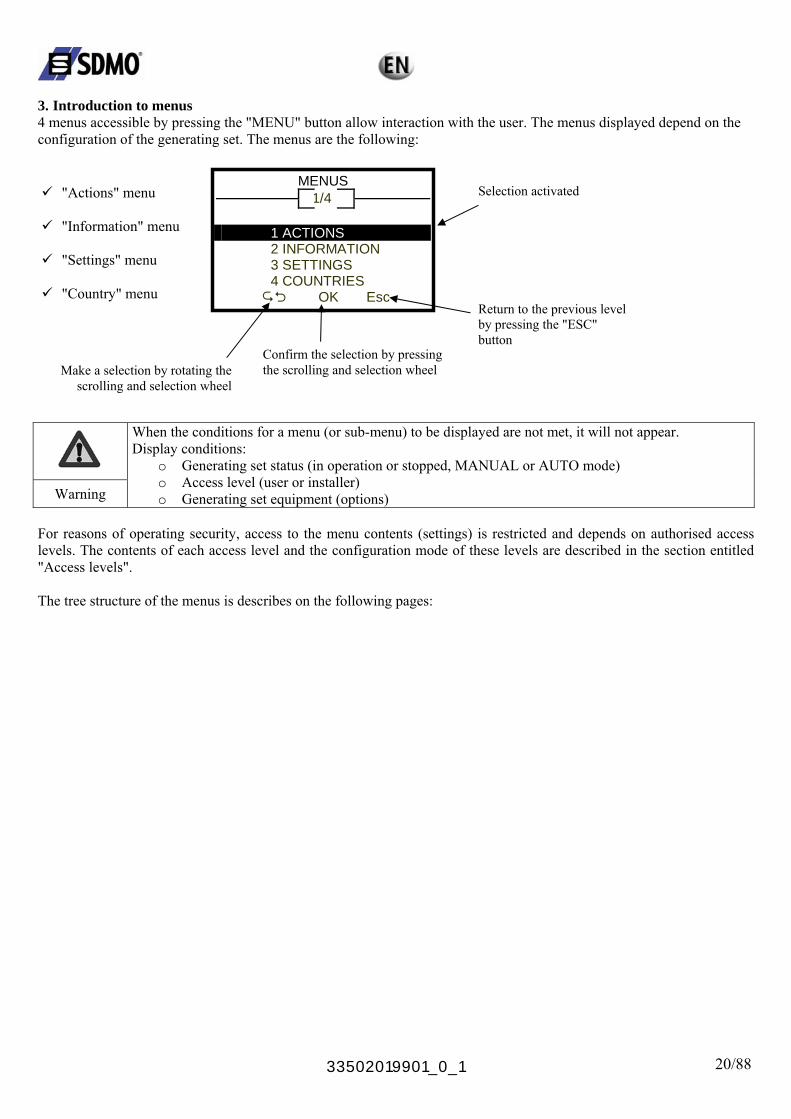
3. Introduction to menus 4 menus accessible by pressing the "MENU" button allow interaction with the user. The menus displayed depend on the configuration of the generating set. The menus are the following:
"Actions" menu MENUS
1/4
"Information" menu
"Settings" menu
"Country" menu
1 ACTIONS
Selection activated
2 INFORMATION 3 SETTINGS 4 COUNTRIES
OK Esc
Return to the previous level by pressing the "ESC" button
Confirm the selection by pressing the scrolling and selection wheel Make a selection by rotating the
scrolling and selection wheel
When the conditions for a menu (or sub-menu) to be displayed are not met, it will not appear. Display conditions:
o Generating set status (in operation or stopped, MANUAL or AUTO mode) o Access level (user or installer)
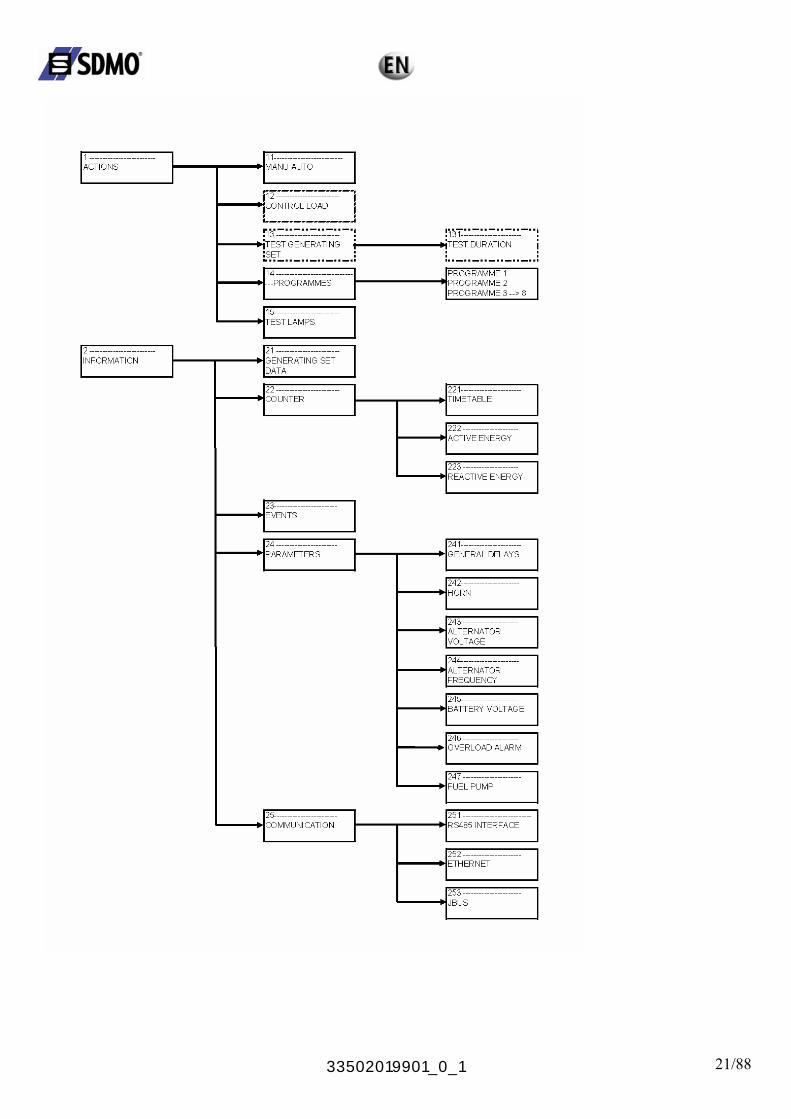
Warning o Generating set equipment (options) For reasons of operating security, access to the menu contents (settings) is restricted and depends on authorised access levels. The contents of each access level and the configuration mode of these levels are described in the section entitled "Access levels". The tree structure of the menus is describes on the following pages:
33502019901_0_1 21/88
33502019901_0_1 22/88
33502019901_0_1 23/88
33502019901_0_1 24/88
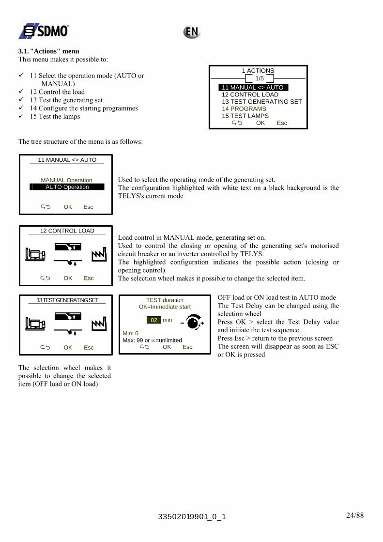
3.1. "Actions" menu This menu makes it possible to:
11 Select the operation mode (AUTO or
MANUAL) 12 Control the load 13 Test the generating set 14 Configure the starting programmes 15 Test the lamps
1 ACTIONS 1/5
11 MANUAL <> AUTO LOAD
EST GENERATING SET
15 TEST LAMPS
12 CONTROL 13 T 14 PROGRAMS
OK Esc
The tree structure of the menu is as follows:
11 MANUAL <> AUTO
MANUAL Operation O AUTO Operation
Function
OK Esc
Used to select the operating mode of the generating set. The configuration highlighted with white text on a black background is the TELYS's current mode
12 CONTROL LOAD
OK Esc
Load control in MANUAL mode, generating set on. Used to control the closing or opening of the generating set's motorised circuit breaker or an inverter controlled by TELYS. The highlighted configuration indicates the possible action (closing or opening control). The selection wheel makes it possible to change the selected item.
13 TEST GENERATING SET OFF load or ON load test in AUTO mode The Test Delay can be changed using the selection wheel Press OK > select the Test Delay value and initiate the test sequence Press Esc > return to the previous screen The screen will disappear as soon as ESC or OK is pressed
TEST duration OK=Immediate start
min
Min: 0
OK Esc
Max: 99 or ∞=unlimited
OK Esc
02
The selection wheel makes it possible to change the selected item (OFF load or ON load)
33502019901_0_1 25/88
14 PROGRAMMES
1/8
PROGRAMME 1
PROGRAMME 2 PROGRAMME 3 PROGRAMME 4
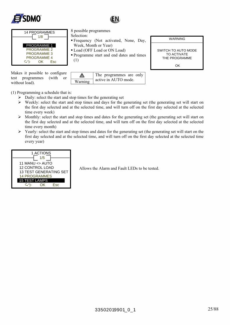
OK Esc Makes it possible to configure test programmes (with or without load).
8 possible programmes Selection: Frequency (Not activated, None, Day, Week, Month or Year) Load (OFF Load or ON Load) Programme start and end dates and times (1)
Warning
The programmes are only active in AUTO mode.
WARNING
SWITCH TO AUTO MODE
TO ACTIVATE THE PROGRAMME
OK
(1) Programming a schedule that is:
Daily: select the start and stop times for the generating set Weekly: select the start and stop times and days for the generating set (the generating set will start on
the first day selected and at the selected time, and will turn off on the first day selected at the selected time every week)
Monthly: select the start and stop times and dates for the generating set (the generating set will start on the first day selected and at the selected time, and will turn off on the first day selected at the selected time every month)
Yearly: select the start and stop times and dates for the generating set (the generating set will start on the first day selected and at the selected time, and will turn off on the first day selected at the selected time every year)
1 ACTIONS 1/5
11 MANU <> AUTO 12 CONTROL LOAD
13 TEST GENERATING SET
14 PROGRAMMES 15 TEST LAMPS
OK Esc
Allows the Alarm and Fault LEDs to be tested.

33502019901_0_1 26/88
3.2. "Information" menu This menu makes it possible to view:
21 the generating set data 22 the counters 23 the events stored in the event history 24 the generating set parameters (displays all the settings values of all the parameters, including those
that are write protected) 25 communication parameters
2 INFORMATION 1/5
21 GENSET DATA
24 PARAMETERS
22 COUNTERS
23 EVENTS
OK Esc
2 INFORMATION 5/5
22 COUNTE 23 EVENTS
RS
24 PARAMETERS 25 COMMUNICATION
OK Esc The tree structure of the menu is as follows:
21 GENSET DATA 1/7
SERIAL No.: 08030010000 SOFTWARE: 5.3.5 NOMINAL VOLTAGE: 400V FREQUENCY: 50Hz
OK Esc
21 GENERATING SET DATA 7/7
Generating set serial no.
FREQUENCY: 50HNOMINAL KW: 320kW PF: 0.80 EARTH SYSTEM: TNS
OK Esc
Software version of TELYS Alternator Nominal Voltage Alternator Nominal Frequency Nominal Active Output Corresponding power factor Neutral Point
22 COUNTERS 1/3
222 ACTIVE ENERGY 223 REACTIVE ENERGY
OK Esc
221 TIMETABLE
221 TIMETABLE
TOTAL: 19358 H 56 min
PARTIAL: 1359 H 30 min
Esc
Total operating hours of the generating set Partial operating hours of the generating set (between 2 successive start-ups)
222 ACTIVE ENERGY
TOTAL: 578902 kWh
PARTIAL: 200 kWh
Esc
Total active energy supplied by the generating set Partial active energy supplied by the generating set (between 2 successive power supplies)
223 REACTIVE ENERGY
TOTAL:
578902 kvarh
PARTIAL: 200 kvarh
Esc
Total reactive energy supplied by the generating set Partial reactive energy supplied by the generating set (between 2 successive power supplies)
33502019901_0_1 27/88
23 EVENTS
005/101
23/08/06 13:46 Press STOP
FAULT 23/08/06 13:45 Fail to start
OK Esc
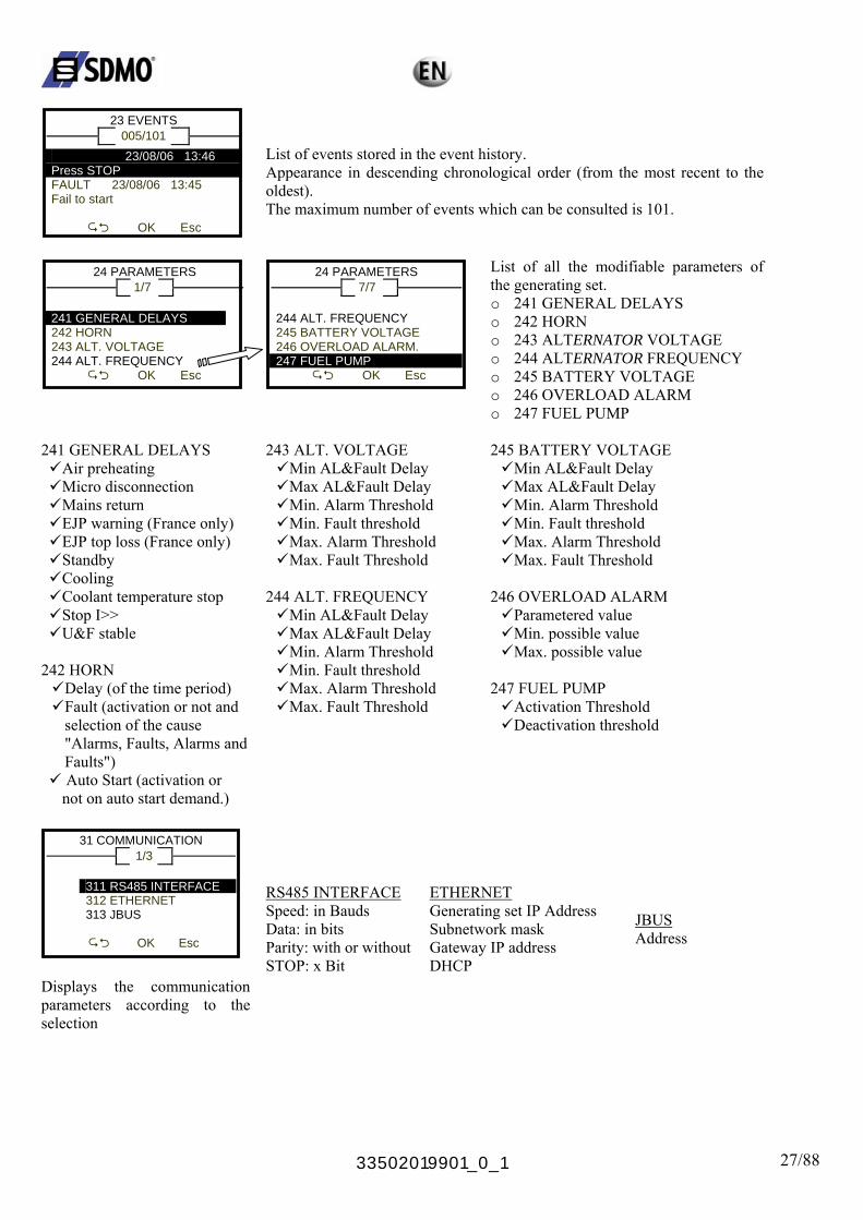
List of events stored in the event history. Appearance in descending chronological order (from the most recent to the oldest). The maximum number of events which can be consulted is 101.
24 PARAMETERS 1/7
241 GENERAL DELAYS
244 ALT. FREQUENCY
242 HORN 243 ALT. VOLTAGE
OK Esc
24 PARAMETERS 7/7
244 A245 BATTERY VOLTAGE 246 OVERLOAD ALARM.
LT. FREQUENCY
247 FUEL PUMP
OK Esc
List of all the modifiable parameters of the generating set. o 241 GENERAL DELAYS o 242 HORN o 243 ALTERNATOR VOLTAGE o 244 ALTERNATOR FREQUENCY o 245 BATTERY VOLTAGE o 246 OVERLOAD ALARM o 247 FUEL PUMP
241 GENERAL DELAYS
Air preheating Micro disconnection Mains return EJP warning (France only) EJP top loss (France only) Standby Cooling Coolant temperature stop Stop I>> U&F stable
242 HORN
Delay (of the time period) Fault (activation or not and selection of the cause "Alarms, Faults, Alarms and Faults") Auto Start (activation or not on auto start demand.)
243 ALT. VOLTAGE
Min AL&Fault Delay Max AL&Fault Delay Min. Alarm Threshold Min. Fault threshold Max. Alarm Threshold Max. Fault Threshold
244 ALT. FREQUENCY
Min AL&Fault Delay Max AL&Fault Delay Min. Alarm Threshold Min. Fault threshold Max. Alarm Threshold Max. Fault Threshold
245 BATTERY VOLTAGE
Min AL&Fault Delay Max AL&Fault Delay Min. Alarm Threshold Min. Fault threshold Max. Alarm Threshold Max. Fault Threshold
246 OVERLOAD ALARM
Parametered value Min. possible value Max. possible value
247 FUEL PUMP
Activation Threshold Deactivation threshold
31 COMMUNICATION 1/3
311 RS485 INTERFACE
JBUS
ETHERNET 312 ETHERNET 313
OK Esc
Displays the communication parameters according to the selection
RS485 INTERFACE Speed: in Bauds Data: in bits Parity: with or without STOP: x Bit
Generating set IP Address Subnetwork mask Gateway IP address DHCP
JBUS Address
33502019901_0_1 28/88
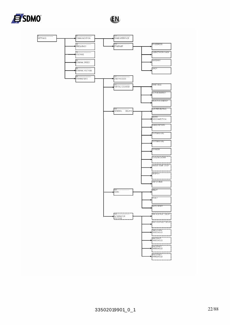
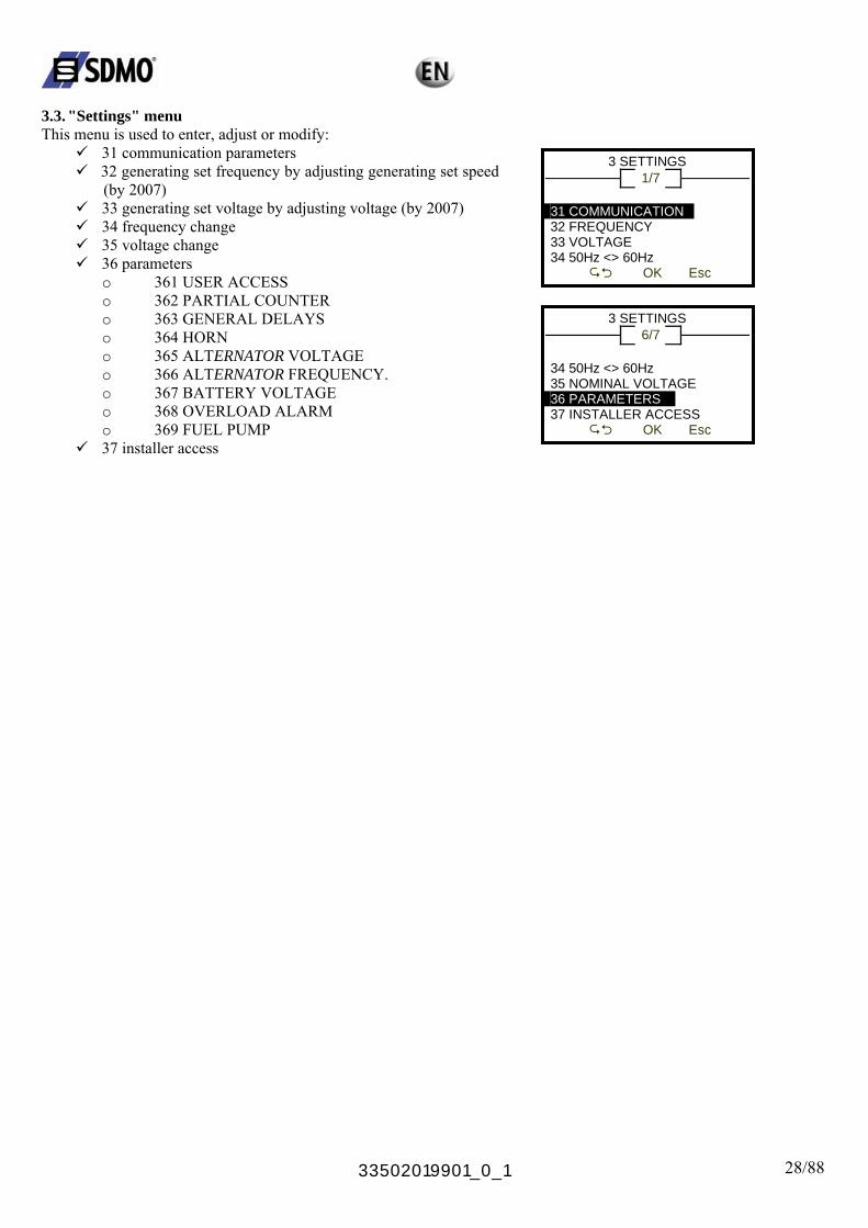
3.3. "Settings" menu This menu is used to enter, adjust or modify:
31 communication parameters 32 generating set frequency by adjusting generating set speed
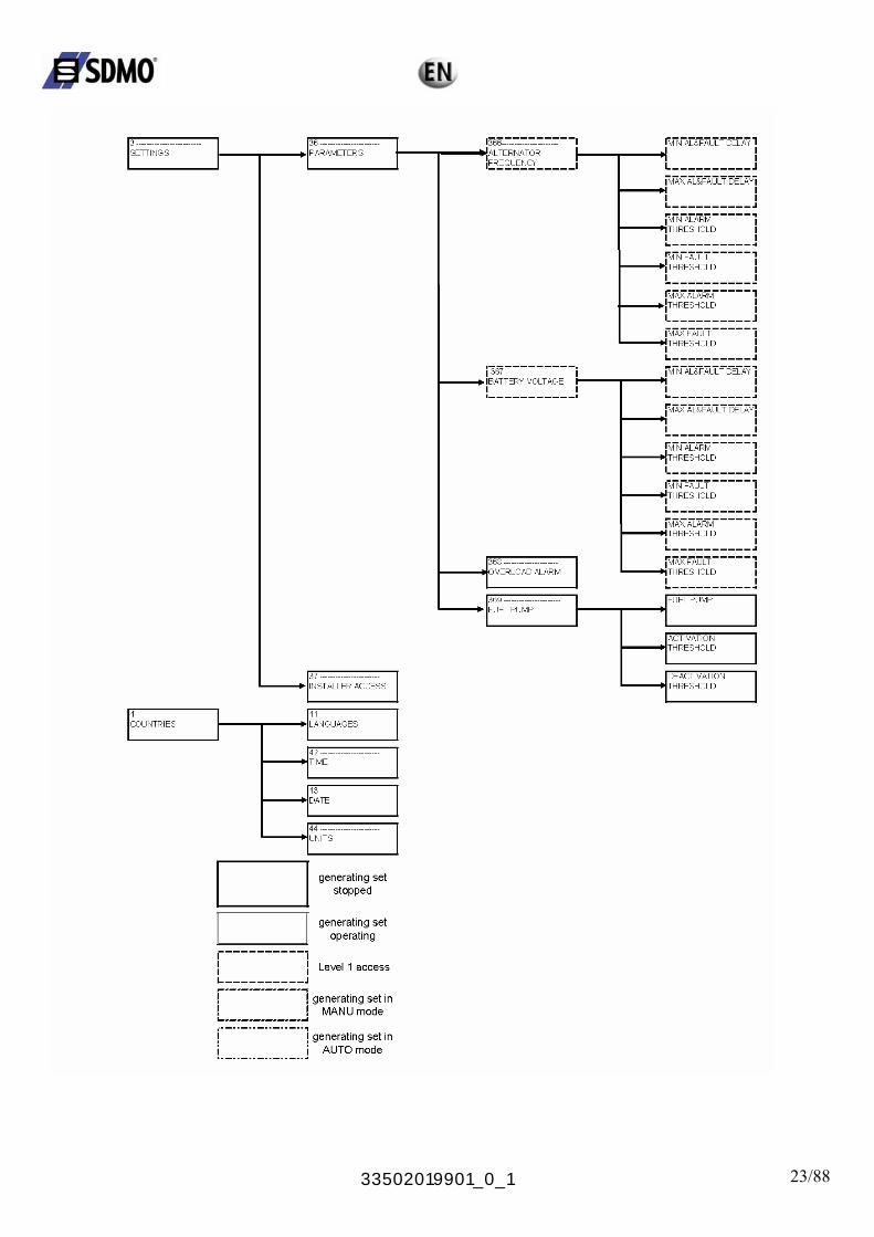
(by 2007) 33 generating set voltage by adjusting voltage (by 2007) 34 frequency change 35 voltage change 36 parameters
o 361 USER ACCESS o 362 PARTIAL COUNTER o 363 GENERAL DELAYS o 364 HORN
3 SETTINGS 1/7
31 COMMUNICATION 32 FREQUENCY 33 VOLTAGE 34 50Hz <> 60Hz
OK Esc
3 SETTINGS 6/7
o 365 ALTERNATOR VOLTAGE 34 50Hz <> 60Hz35 NOMINAL VOLTAGE
o 366 ALTERNATOR FREQUENCY. o 367 BATTERY VOLTAGE 36 PARAMETERS
37 INSTALLER ACCESS
o 368 OVERLOAD ALARM OK Esc o 369 FUEL PUMP 37 installer access
33502019901_0_1 29/88
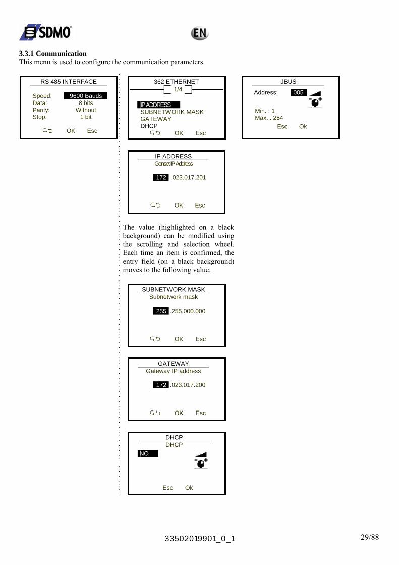
3.3.1 Communication This menu is used to configure the communication parameters.
RS 485 INTERFACE
Speed: 9600 Bauds
Data: 8 bits Parity: Without Stop: 1 bit
OK Esc
362 ETHERNET 1/4
JBUS
3 IP ADDRESS
DHCP
SUBNETWORK MASK GATEWAY
OK Esc
IP ADDRESS
Genset IP Address
172
.023.017.201
OK Esc
The value (highlighted on a black background) can be modified using the scrolling and selection wheel. Each time an item is confirmed, the entry field (on a black background) moves to the following value.
SUBNETWORK MASK
Subnetwork mask
255
.255.000.000
OK Esc
GATEWAY
Gateway IP address
172
.023.017.200
OK Esc
DHCP
DHCP
NO
Esc Ok
Address: 005
Min. : 1 Max. : 254
Esc Ok
33502019901_0_1 30/88
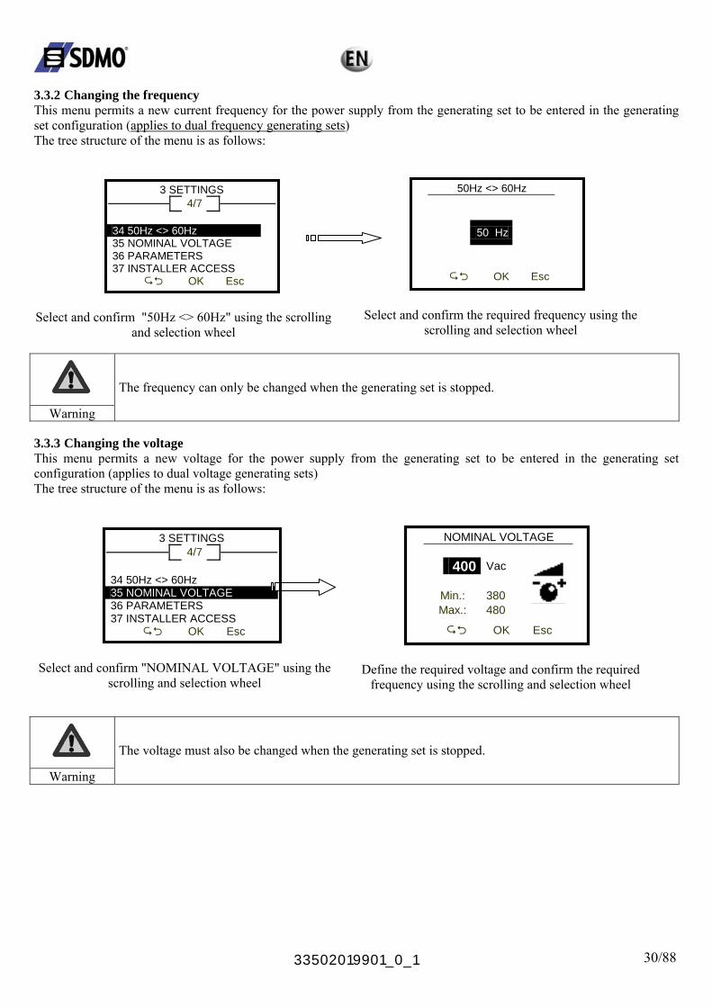
3.3.2 Changing the frequency This menu permits a new current frequency for the power supply from the generating set to be entered in the generating set configuration (applies to dual frequency generating sets) The tree structure of the menu is as follows:
3 SETTINGS 4/7
34 50Hz <> 60Hz 35 NOMINAL VOLTAGE 36 PARAMETERS 37 INSTALLER ACCESS
OK Esc
Select and confirm "50Hz <> 60Hz" using the scrolling and selection wheel
50Hz <> 60Hz
50 Hz
OK Esc
Select and confirm the required frequency using the
scrolling and selection wheel
The frequency can only be changed when the generating set is stopped.
Warning 3.3.3 Changing the voltage This menu permits a new voltage for the power supply from the generating set to be entered in the generating set configuration (applies to dual voltage generating sets) The tree structure of the menu is as follows:
3 SETTINGS 4/7
34 50Hz <> 60Hz 35 NOMINAL VOLTAGE 36 PARAMETERS 37 INSTALLER ACCESS
OK Esc
Select and confirm "NOMINAL VOLTAGE" using the
scrolling and selection wheel
NOMINAL VOLTAGE 400 Vac
Min.: 380
Max.: 480
OK Esc
Define the required voltage and confirm the required
frequency using the scrolling and selection wheel
The voltage must also be changed when the generating set is stopped.
Warning

33502019901_0_1 31/88
3.3.4 Parameter settings With the generating set off, this menu can be used to adjust or modify:
36 the following parameters: (list of parameters and example screens)
o 361 USER ACCESS
USER ACCESS
Create password
*
* * *
OK Esc
SECURE ACCESS
Enter password
*
* * *
OK Esc
Makes it possible to create a user password
Screen displayed if the customer has entered an access code in menu 3 SETTINGS > 361 Create password Reset by entering the code 1966
o 362 PARTIAL COUNTER Timetable Active energy Reactive energy
TIMETABLE
RESET?
Esc OK
0 h 0 min
ACTIVE ENERGY
RESET?
Esc OK
REACTIVE ENERGY
0 kWh
r RESET?
Esc OK
0 kVa
o 363 GENERAL DELAYS Air preheating Micro disconnection Mains return EJP warning (France only) EJP top loss (France only) STANDBY Cooling (access protected => "installer access" level) Coolant temperature stop (access protected => "installer access" level) Stop I>> (access protected => "installer access" level) Stabilisation U & F
AIR PREHEATING
10 Sec Min. : 0 Max. : 99
Esc OK
MICRO DISCONNECTION 05 Sec Min. : 0 Max. : 99
MAINS RETURN
Esc OK
01 Min Min. : 0 Max. : 99
Esc OK
33502019901_0_1 32/88
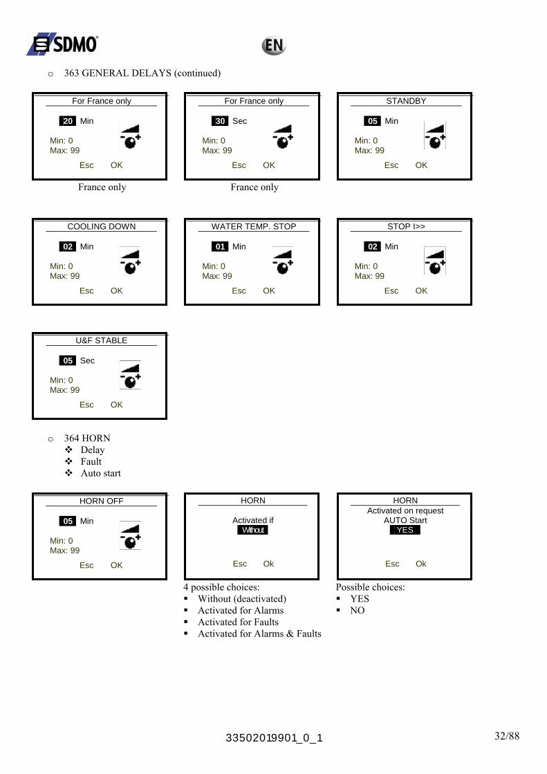
o 363 GENERAL DELAYS (continued)
For France only
20 Min Min: 0 Max: 99
Esc OK
France only
For France only
30 Sec Min: 0 Max: 99
Esc OK
France only
STANDBY
05 Min Min: 0 Max: 99
Esc OK
COOLING DOWN
02 Min Min: 0 Max: 99
WATER TEMP. STOP
Esc OK
01 Min Min: 0 Max: 99
Esc OK
STOP I>>
02 Min Min: 0 Max: 99
Esc OK
U&F STABLE 05 Sec Min: 0 Max: 99
Esc OK
o 364 HORN Delay Fault Auto start
HORN OFF
05 Min Min: 0 Max: 99
Esc OK
HORN
Activated if Without
Esc Ok
HORN
A t ctivated on reques
AUTO Start YES
Esc Ok
4 possible choices: Without (deactivated) Activated for Alarms
Possible choices: YES NO
Activated for Faults Activated for Alarms & Faults
33502019901_0_1 33/88
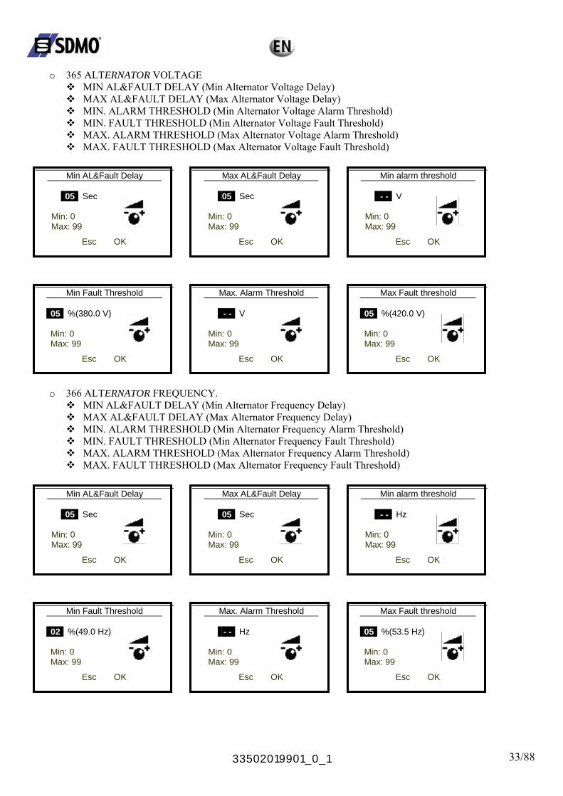
o 365 ALTERNATOR VOLTAGE
MIN AL&FAULT DELAY (Min Alternator Voltage Delay) MAX AL&FAULT DELAY (Max Alternator Voltage Delay) MIN. ALARM THRESHOLD (Min Alternator Voltage Alarm Threshold) MIN. FAULT THRESHOLD (Min Alternator Voltage Fault Threshold) MAX. ALARM THRESHOLD (Max Alternator Voltage Alarm Threshold) MAX. FAULT THRESHOLD (Max Alternator Voltage Fault Threshold)
Min AL&Fault Delay
05 Sec Min: 0 Max: 99
Max AL&Fault Delay
Esc OK
05 Sec Min: 0 Max: 99
Esc OK
Min alarm threshold
- - V Min: 0 Max: 99
Esc OK
Min Fault Threshold 05 %(380.0 V) Min: 0 Max: 99
Max. Alarm Threshold
Esc OK
- - V Min: 0 Max: 99
Esc OK
Max Fault threshold
05 %(420.0 V) Min: 0 Max: 99
Esc OK
o 366 ALTERNATOR FREQUENCY.
MIN AL&FAULT DELAY (Min Alternator Frequency Delay) MAX AL&FAULT DELAY (Max Alternator Frequency Delay) MIN. ALARM THRESHOLD (Min Alternator Frequency Alarm Threshold) MIN. FAULT THRESHOLD (Min Alternator Frequency Fault Threshold) MAX. ALARM THRESHOLD (Max Alternator Frequency Alarm Threshold) MAX. FAULT THRESHOLD (Max Alternator Frequency Fault Threshold)
Min AL&Fault Delay
05 Sec Min: 0 Max: 99
Max AL&Fault Delay
Esc OK
05 Sec Min: 0 Max: 99
Esc OK
Min alarm threshold
- - Hz Min: 0 Max: 99
Esc OK
Min Fault Threshold
02 %(49.0 Hz) Min: 0 Max: 99
Max. Alarm Threshold
Esc OK
- - Hz Min: 0 Max: 99
Esc OK
Max Fault threshold
05 %(53.5 Hz) Min: 0 Max: 99
Esc OK
33502019901_0_1 34/88
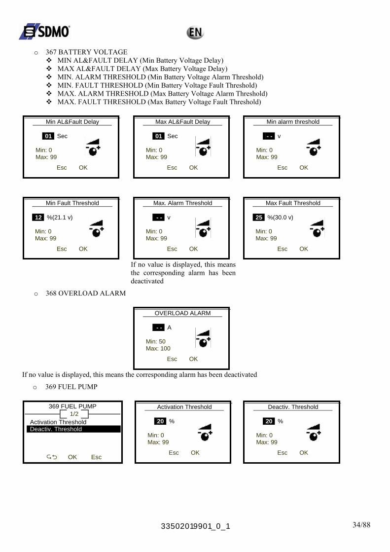
o 367 BATTERY VOLTAGE
MIN AL&FAULT DELAY (Min Battery Voltage Delay) MAX AL&FAULT DELAY (Max Battery Voltage Delay) MIN. ALARM THRESHOLD (Min Battery Voltage Alarm Threshold) MIN. FAULT THRESHOLD (Min Battery Voltage Fault Threshold) MAX. ALARM THRESHOLD (Max Battery Voltage Alarm Threshold) MAX. FAULT THRESHOLD (Max Battery Voltage Fault Threshold)
Min AL&Fault Delay
01 Sec Min: 0 Max: 99
Max AL&Fault Delay
Esc OK
01 Sec Min: 0 Max: 99
Esc OK
Min alarm threshold
- - v Min: 0 Max: 99
Esc OK
Min Fault Threshold 12 %(21.1 v) Min: 0 Max: 99
Esc OK
Max. Alarm Threshold
- - v Min: 0 Max: 99
Max Fault Threshold
25 %(30.0 v) Min: 0 Max: 99
Esc OK
Esc OK
If no value is displayed, this means the corresponding alarm has been deactivated
o 368 OVERLOAD ALARM
OVERLOAD ALARM - - A Min: 50 Max: 100
Esc OK
If no value is displayed, this means the corresponding alarm has been deactivated
o 369 FUEL PUMP
369 FUEL PUMP 1/2
Activation Threshold
Activation Threshold Deactiv. Threshold
OK Esc
20 % Min: 0 Max: 99
Deactiv. Threshold
Esc OK
20 % Min: 0 Max: 99
Esc OK
33502019901_0_1 35/88
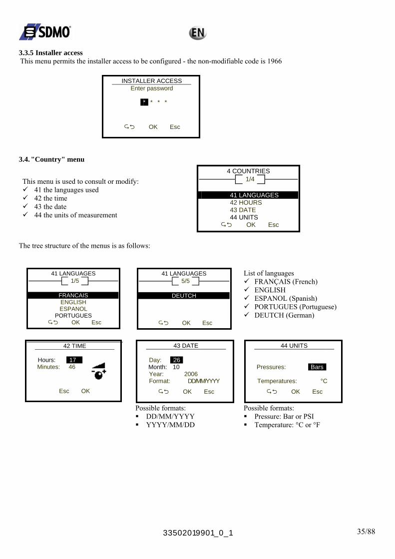
3.3.5 Installer access This menu permits the installer access to be configured - the non-modifiable code is 1966
INSTALLER ACCESS Enter password
*
* * *
OK Esc
3.4. "Country" menu
This menu is used to consult or modify: 41 the languages used 42 the time 43 the date 44 the units of measurement
4 COUNTRIES 1/4
41 LANGUAGES
44 UNITS
42 HOURS 43 DATE
OK Esc
The tree structure of the menus is as follows:
41 LANGUAGES
1/5
41 LANGUAGES
FRANCAIS
PORTUGUES
5/5
DEUTCH
ENGLISH ESPANOL
OK Esc
OK Esc
List of languages FRANÇAIS (French) ENGLISH ESPANOL (Spanish) PORTUGUES (Portuguese) DEUTCH (German)
42 TIME
Hours: 17 Minutes: 46
Esc OK
43 DATE
Day: 26
Month: 10
44 UNITS
Pressures:
Year: 2006 Format: DD/MM/YYYY
OK Esc
Bars
Temperatures: °C
OK Esc
Possible formats: Possible formats: DD/MM/YYYY Pressure: Bar or PSI YYYY/MM/DD Temperature: °C or °F
33502019901_0_1 36/88
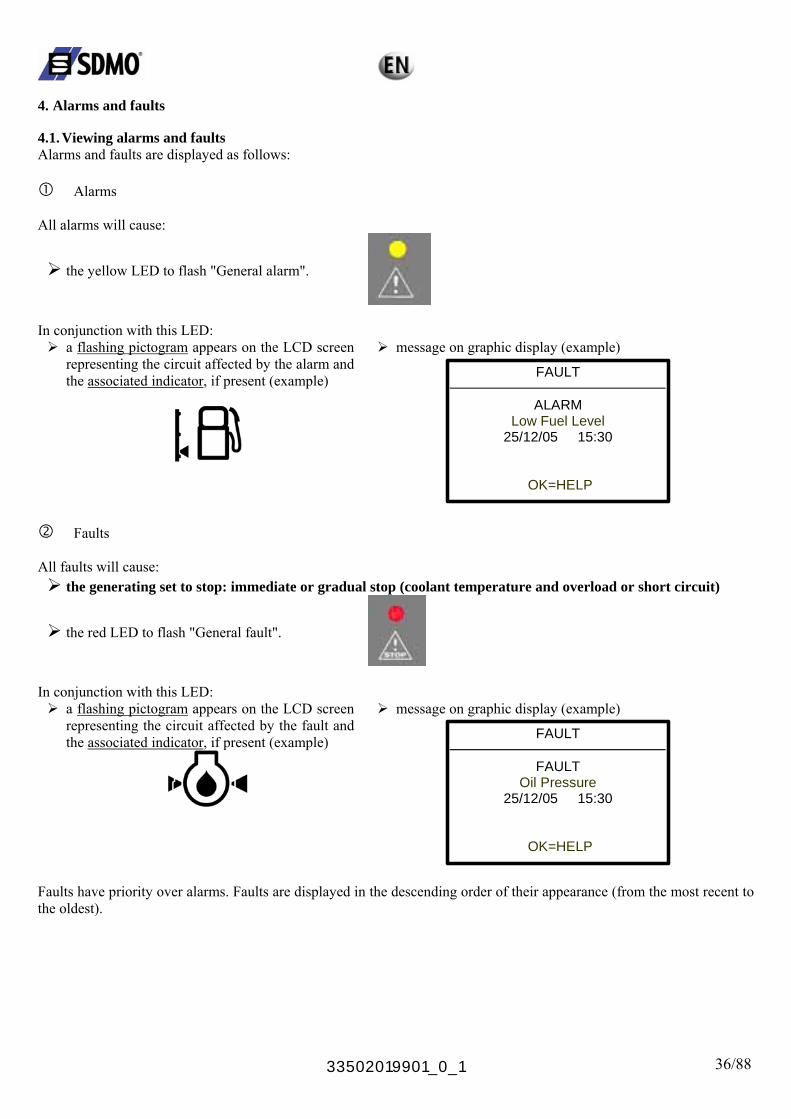
4. Alarms and faults 4.1. Viewing alarms and faults Alarms and faults are displayed as follows:
Alarms All alarms will cause:
the yellow LED to flash "General alarm".
In conjunction with this LED:
a flashing pictogram appears on the LCD screen representing the circuit affected by the alarm and the associated indicator, if present (example)
message on graphic display (example)
FAULT
ALARM
Low Fuel Level
OK=HELP
25/12/05 15:30
Faults All faults will cause:
the generating set to stop: immediate or gradual stop (coolant temperature and overload or short circuit)
the red LED to flash "General fault".
In conjunction with this LED:
a flashing pictogram appears on the LCD screen representing the circuit affected by the fault and the associated indicator
message on graphic display (example)
FAULT
FAULT
, if present (example)
Oil Pressure
OK=HELP
25/12/05 15:30
Faults have priority over alarms. Faults are displayed in the descending order of their appearance (from the most recent to the oldest).
33502019901_0_1 37/88
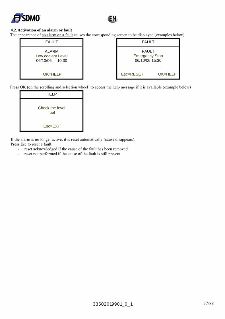
4.2. Activation of an alarm or fault The appearance of an alarm or a fault causes the corresponding screen to be displayed (examples below)
FAULT
ALARM
06/10/06 10:30
Low coolant Level
OK=HELP
FAULT
FAULT Emergency Stop
Esc=RESET OK=HELP
06/10/06 15:30
Press OK (on the scrolling and selection wheel) to access the help message if it is available (example below)
HELP
Check the level
fuel
Esc=EXIT
If the alarm is no longer active, it is reset automatically (cause disappears). Press Esc to reset a fault:
- reset acknowledged if the cause of the fault has been removed - reset not performed if the cause of the fault is still present.

33502019901_0_1 38/88
4.3. Activation of an alarm and a fault The appearance of an alarm and a fault causes:
The yellow and red LEDs to flash the related screen to be displayed (example below)
FAULTS 1/2
FAULT Emergency Stop
Esc=RESET OK=LIST
25/12/05 15:30
If several faults are present, the number of faults is displayed at the top of the screen.
The faults list can be accessed by pressing OK (of the scrolling and selection wheel) (examples below)
FAULTS 1/2
FAULT 25/12/05 15:30
Emergency Stop ALARM 25/12/05 15:30 Low Fuel Level
OK=HELP Esc
Press Esc to return to the previous screen. Press OK to go to the HELP screen (help on the highlighted fault) Use the scrolling and selection wheel to scroll through the list of faults.
HELP
Check: - Emerg. Stop Pos. - Connector(s)
Esc
If the alarm is no longer active, it is reset automatically (cause disappears). Press Esc to reset a fault:
- reset acknowledged if the cause of the fault has been removed - reset not performed if the cause of the fault is still present.
33502019901_0_1 39/88
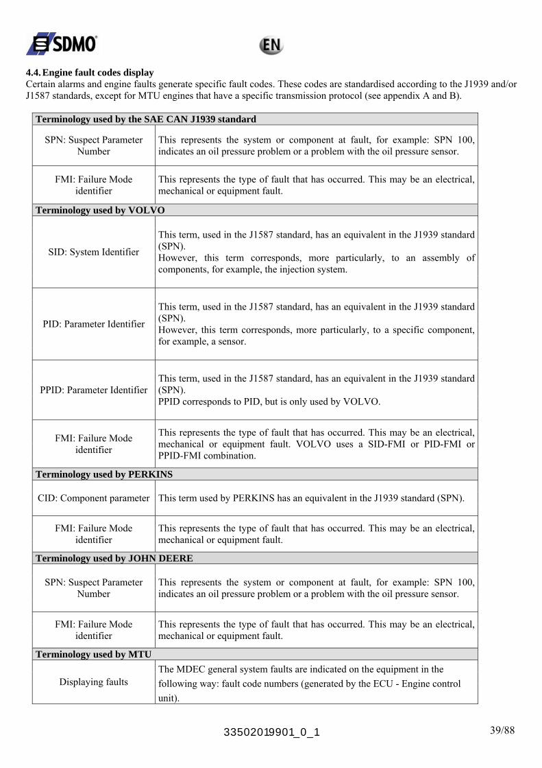
4.4. Engine fault codes display Certain alarms and engine faults generate specific fault codes. These codes are standardised according to the J1939 and/or J1587 standards, except for MTU engines that have a specific transmission protocol (see appendix A and B).
Terminology used by the SAE CAN J1939 standard
SPN: Suspect Parameter Number
This represents the system or component at fault, for example: SPN 100, indicates an oil pressure problem or a problem with the oil pressure sensor.
FMI: Failure Mode identifier
This represents the type of fault that has occurred. This may be an electrical, mechanical or equipment fault.
Terminology used by VOLVO
SID: System Identifier
This term, used in the J1587 standard, has an equivalent in the J1939 standard (SPN). However, this term corresponds, more particularly, to an assembly of components, for example, the injection system.
PID: Parameter Identifier
This term, used in the J1587 standard, has an equivalent in the J1939 standard (SPN). However, this term corresponds, more particularly, to a specific component, for example, a sensor.
PPID: Parameter Identifier This term, used in the J1587 standard, has an equivalent in the J1939 standard (SPN). PPID corresponds to PID, but is only used by VOLVO.
FMI: Failure Mode identifier
This represents the type of fault that has occurred. This may be an electrical, mechanical or equipment fault. VOLVO uses a SID-FMI or PID-FMI or PPID-FMI combination.
Terminology used by PERKINS
CID: Component parameter This term used by PERKINS has an equivalent in the J1939 standard (SPN).
FMI: Failure Mode identifier
This represents the type of fault that has occurred. This may be an electrical, mechanical or equipment fault.
Terminology used by JOHN DEERE
SPN: Suspect Parameter Number
This represents the system or component at fault, for example: SPN 100, indicates an oil pressure problem or a problem with the oil pressure sensor.
FMI: Failure Mode identifier
This represents the type of fault that has occurred. This may be an electrical, mechanical or equipment fault.
Terminology used by MTU
Displaying faults The MDEC general system faults are indicated on the equipment in the following way: fault code numbers (generated by the ECU - Engine control unit).
33502019901_0_1 40/88
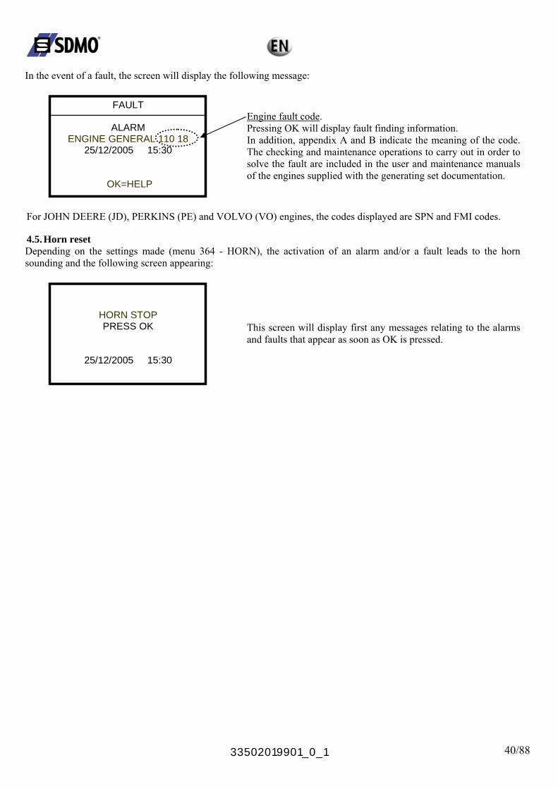
In the event of a fault, the screen will display the following message:
FAULT
ENGINE GENERAL 110 18
OK=HELP
ALARM
25/12/2005
Engine fault code.
15:30
Pressing OK will display fault finding information. In addition, appendix A and B indicate the meaning of the code. The checking and maintenance operations to carry out in order to solve the fault are included in the user and maintenance manuals of the engines supplied with the generating set documentation.
For JOHN DEERE (JD), PERKINS (PE) and VOLVO (VO) engines, the codes displayed are SPN and FMI codes. 4.5. Horn reset Depending on the settings made (menu 364 - HORN), the activation of an alarm and/or a fault leads to the horn sounding and the following screen appearing:
HORN STOP
PRESS OK
25/12/2005 15:30
This screen will display first any messages relating to the alarms and faults that appear as soon as OK is pressed.
33502019901_0_1 41/88
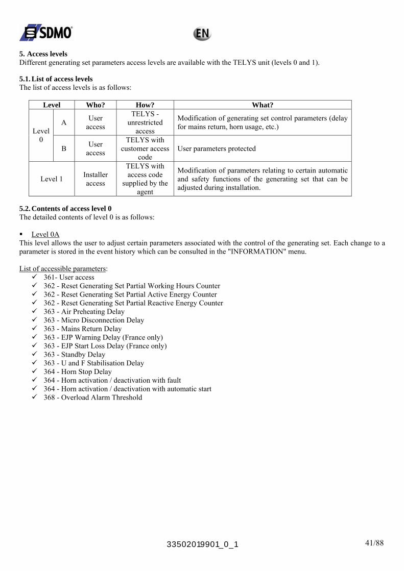
5. Access levels Different generating set parameters access levels are available with the TELYS unit (levels 0 and 1). 5.1. List of access levels The list of access levels is as follows:
Level Who? How? What?
A User access
TELYS - unrestricted
access
Modification of generating set control parameters (delay for mains return, horn usage, etc.) Level
0 B User
access
TELYS with customer access
code User parameters protected
Level 1 Installer access
TELYS with access code
supplied by the agent
Modification of parameters relating to certain automatic and safety functions of the generating set that can be adjusted during installation.
5.2. Contents of access level 0 The detailed contents of level 0 is as follows: Level 0A
This level allows the user to adjust certain parameters associated with the control of the generating set. Each change to a parameter is stored in the event history which can be consulted in the "INFORMATION" menu. List of accessible parameters:
361- User access 362 - Reset Generating Set Partial Working Hours Counter 362 - Reset Generating Set Partial Active Energy Counter 362 - Reset Generating Set Partial Reactive Energy Counter 363 - Air Preheating Delay 363 - Micro Disconnection Delay 363 - Mains Return Delay 363 - EJP Warning Delay (France only) 363 - EJP Start Loss Delay (France only) 363 - Standby Delay 363 - U and F Stabilisation Delay 364 - Horn Stop Delay 364 - Horn activation / deactivation with fault 364 - Horn activation / deactivation with automatic start 368 - Overload Alarm Threshold
33502019901_0_1 42/88
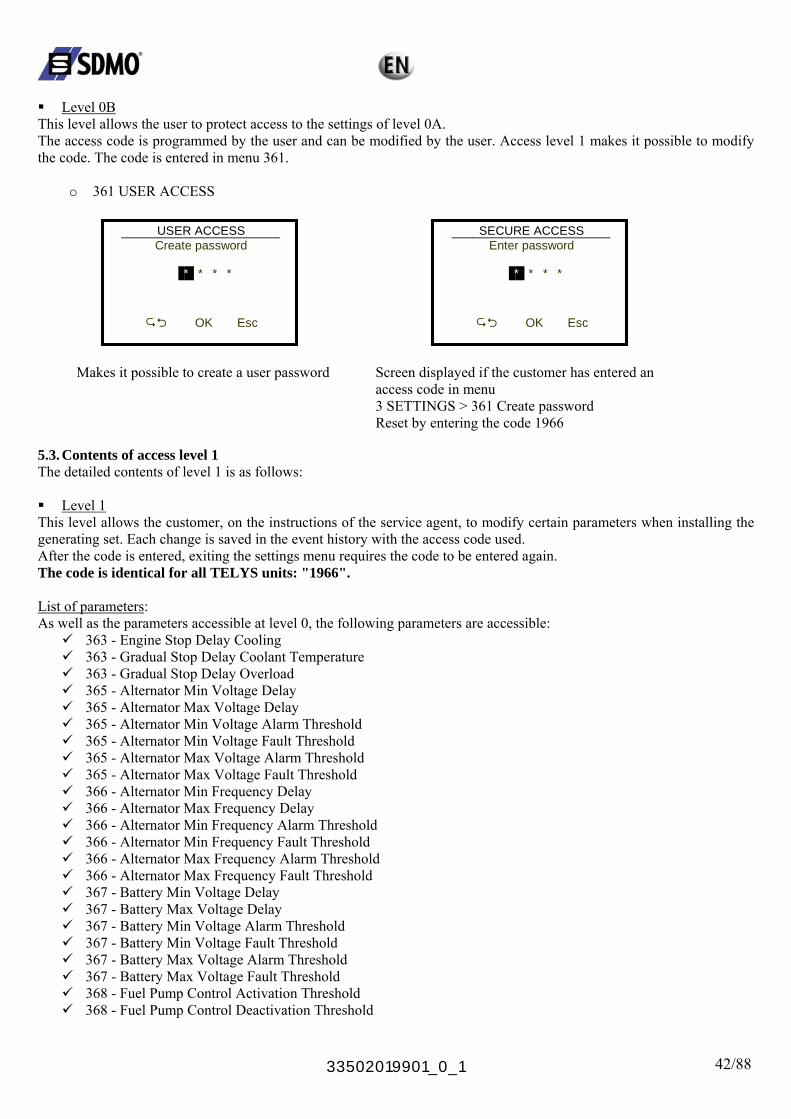
Level 0B
This level allows the user to protect access to the settings of level 0A. The access code is programmed by the user and can be modified by the user. Access level 1 makes it possible to modify the code. The code is entered in menu 361.
o 361 USER ACCESS
USER ACCESS
SECURE ACCESS
Create password
*
Enter password * * *
OK Esc
Makes it possible to create a user password
*
* * *
OK Esc
Screen displayed if the customer has entered an access code in menu 3 SETTINGS > 361 Create password Reset by entering the code 1966
5.3. Contents of access level 1 The detailed contents of level 1 is as follows: Level 1
This level allows the customer, on the instructions of the service agent, to modify certain parameters when installing the generating set. Each change is saved in the event history with the access code used. After the code is entered, exiting the settings menu requires the code to be entered again. The code is identical for all TELYS units: "1966". List of parameters: As well as the parameters accessible at level 0, the following parameters are accessible:
363 - Engine Stop Delay Cooling 363 - Gradual Stop Delay Coolant Temperature 363 - Gradual Stop Delay Overload 365 - Alternator Min Voltage Delay 365 - Alternator Max Voltage Delay 365 - Alternator Min Voltage Alarm Threshold 365 - Alternator Min Voltage Fault Threshold 365 - Alternator Max Voltage Alarm Threshold 365 - Alternator Max Voltage Fault Threshold 366 - Alternator Min Frequency Delay 366 - Alternator Max Frequency Delay 366 - Alternator Min Frequency Alarm Threshold 366 - Alternator Min Frequency Fault Threshold 366 - Alternator Max Frequency Alarm Threshold 366 - Alternator Max Frequency Fault Threshold 367 - Battery Min Voltage Delay 367 - Battery Max Voltage Delay 367 - Battery Min Voltage Alarm Threshold 367 - Battery Min Voltage Fault Threshold 367 - Battery Max Voltage Alarm Threshold 367 - Battery Max Voltage Fault Threshold 368 - Fuel Pump Control Activation Threshold 368 - Fuel Pump Control Deactivation Threshold
33502019901_0_1 43/88
6. Exterior communication Control of the generating set and viewing of the operating parameters can be carried out remotely, without having to install specific software, via a computer network, a landline telephone network or a mobile telephone network. The external communication of TELYS, is the devices integrated to the main board that make external communication possible. Each communication mode conforms to the international standards in force. All the communication ports can be used simultaneously. 6.1. Series communication with the RS485 port This communication port is used for a permanent or non-permanent connection between TELYS and the following equipment:
a PC type computer a programmable logic controller (PLC) a modem all equipment fitted with an RS485 interface
The parameters of this port are as follows: o speed: communication speed 2400, 4800, 9600, 19200, 38400 Bauds o data: data format: 7 or 8 bits o parity: parity check: without, even, odd, o stop: stop bit: yes or no. o address no.: from 1 to 255 o signal type: Rx, Tx, transmission and reception of data o signal transmission: twisted pair armoured cable.
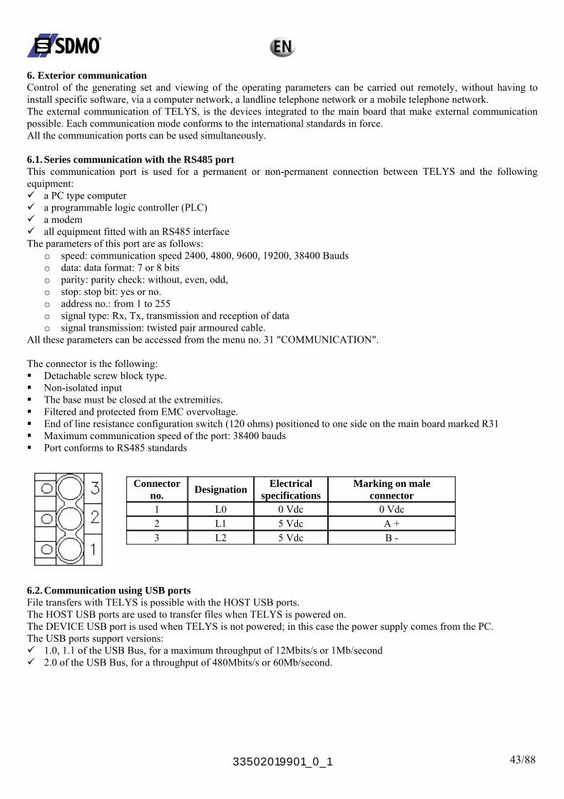
All these parameters can be accessed from the menu no. 31 "COMMUNICATION". The connector is the following: Detachable screw block type. Non-isolated input The base must be closed at the extremities. Filtered and protected from EMC overvoltage. End of line resistance configuration switch (120 ohms) positioned to one side on the main board marked R31 Maximum communication speed of the port: 38400 bauds Port conforms to RS485 standards
Connector
no. Designation Electrical specifications
Marking on male connector
1 L0 0 Vdc 0 Vdc 2 L1 5 Vdc A + 3 L2 5 Vdc B -
6.2. Communication using USB ports File transfers with TELYS is possible with the HOST USB ports. The HOST USB ports are used to transfer files when TELYS is powered on. The DEVICE USB port is used when TELYS is not powered; in this case the power supply comes from the PC. The USB ports support versions:
1.0, 1.1 of the USB Bus, for a maximum throughput of 12Mbits/s or 1Mb/second 2.0 of the USB Bus, for a throughput of 480Mbits/s or 60Mb/second.
33502019901_0_1 44/88
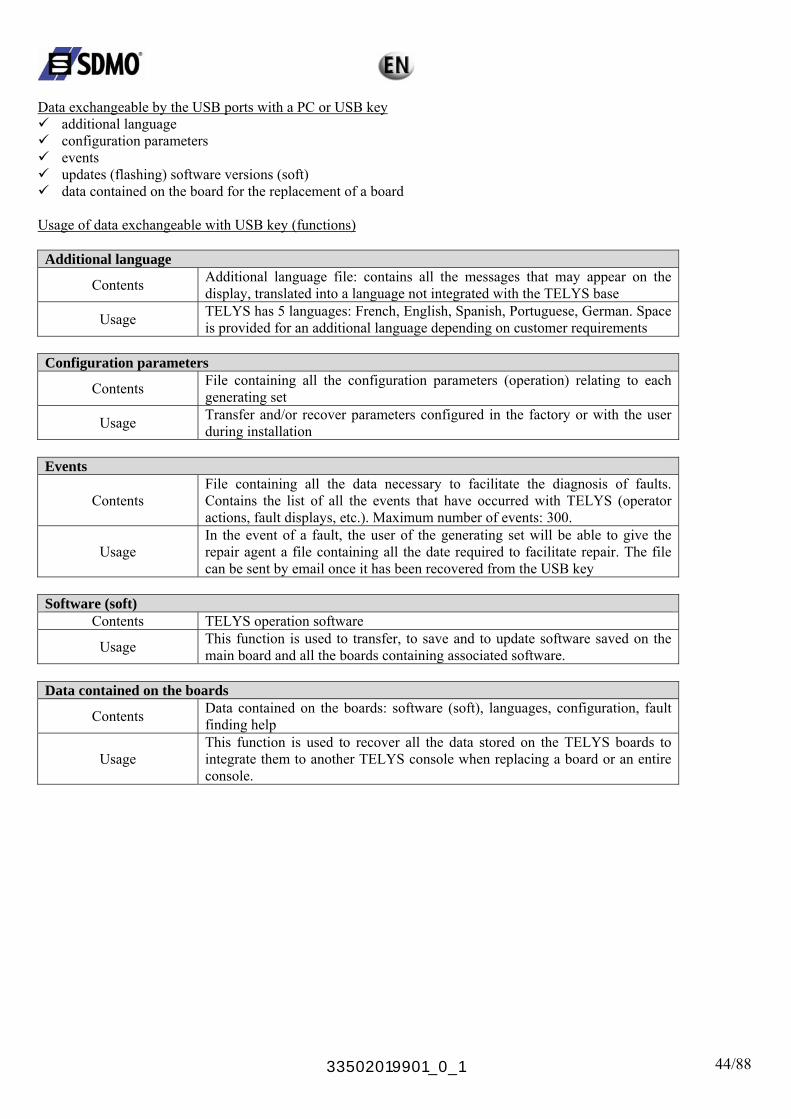
Data exchangeable by the USB ports with a PC or USB key
additional language configuration parameters events updates (flashing) software versions (soft) data contained on the board for the replacement of a board
Usage of data exchangeable with USB key (functions) Additional language
Contents Additional language file: contains all the messages that may appear on the display, translated into a language not integrated with the TELYS base
Usage TELYS has 5 languages: French, English, Spanish, Portuguese, German. Space is provided for an additional language depending on customer requirements
Configuration parameters
Contents File containing all the configuration parameters (operation) relating to each generating set
Usage Transfer and/or recover parameters configured in the factory or with the user during installation
Events
Contents File containing all the data necessary to facilitate the diagnosis of faults. Contains the list of all the events that have occurred with TELYS (operator actions, fault displays, etc.). Maximum number of events: 300.
Usage In the event of a fault, the user of the generating set will be able to give the repair agent a file containing all the date required to facilitate repair. The file can be sent by email once it has been recovered from the USB key
Software (soft)
Contents TELYS operation software
Usage This function is used to transfer, to save and to update software saved on the main board and all the boards containing associated software.
Data contained on the boards
Contents Data contained on the boards: software (soft), languages, configuration, fault finding help
Usage This function is used to recover all the data stored on the TELYS boards to integrate them to another TELYS console when replacing a board or an entire console.
33502019901_0_1 45/88
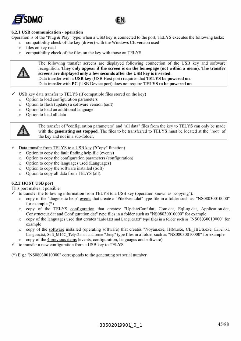
6.2.1 USB communication - operation Operation is of the "Plug & Play" type: when a USB key is connected to the port, TELYS executes the following tasks:
o compatibility check of the key (driver) with the Windows CE version used o files on key read o compatibility check of the files on the key with those on TELYS.
The following transfer screens are displayed following connection of the USB key and software recognition. They only appear if the screen is on the homepage (not within a menu). The transfer screens are displayed only a few seconds after the USB key is inserted.
Data transfer with a USB key (USB Host port) requires that TELYS be powered on. Data transfer with PC (USB Device port) does not require TELYS to be powered on
USB key data transfer to TELYS (if compatible files stored on the key)
o Option to load configuration parameters o Option to flash (update) a software version (soft) o Option to load an additional language o Option to load all data
The transfer of "configuration parameters" and "all data" files from the key to TELYS can only be made with the generating set stopped. The files to be transferred to TELYS must be located at the "root" of the key and not in a sub-folder.
Data transfer from TELYS to a USB key ("Copy" function)
o Option to copy the fault finding help file (events) o Option to copy the configuration parameters (configuration) o Option to copy the languages used (Languages) o Option to copy the software installed (Soft) o Option to copy all data from TELYS (all).
6.2.2 HOST USB port This port makes it possible:
to transfer the following information from TELYS to a USB key (operation known as "copying"): o copy of the "diagnostic help" events that create a "PileEvent.dat" type file in a folder such as: "NS08030010000"
for example (*) o copy of the TELYS configuration that creates: "UpdateConf.dat, Com.dat, EqLog.dat, Application.dat,
Constructeur.dat and Configuration.dat" type files in a folder such as "NS08030010000" for example o copy of the languages used that creates "Label.txt and Langues.txt" type files in a folder such as "NS08030010000" for
example o copy of the software installed (operating software) that creates "Noyau.exe, IHM.exe, CE_JBUS.exe, Label.txt,
Langues.txt, Soft_M16C_Telys2.mot and some *.bmp" type files in a folder such as "NS08030010000" for example o copy of the 4 previous items (events, configuration, languages and software).
to transfer a new configuration from a USB key to TELYS. (*) E.g.: "NS08030010000" corresponds to the generating set serial number.

33502019901_0_1 46/88
TELYS to USB transfer screens
USB 1/6
USB
Download Events
Download Software
5/6
Download Configuration Download Languages
OK Esc
Download Configuration
ftwareDownload Languages Download So Download All
OK Esc
When the transfer is completed, the following screen appears:
USB
Completed
Esc
File Transfer
to transfer the following information from a USB key to TELYS (operation known as "copying"):
o configuration parameters o software version o additional language o all data.
USB to TELYS transfer screens
The transfer screens are displayed following connection of the USB key and software recognition. They only appear if the screen is on the homepage (not within a menu). The transfer screens are displayed only a few seconds after the USB key is inserted.
Data transfer with a USB key (USB Host port) requires that TELYS be powered on.
The transfer of "configuration parameters" and "all data" files from the key to TELYS can only be made with the generating set stopped. The files to be transferred to TELYS must be located at the "root" of the key and not in a sub-folder.
USB 6/6
Download Languages Download Software Download All Upload Configuration
OK Esc
Example of screen
Note: once loading is complete, TELYS will reinitialise itself.

33502019901_0_1 47/88
6.2.3 DEVICE USB port This port makes it possible:
to transfer from TELYS to a PC the same information as that transferred via USB key (events, configuration, languages, software and these 4 items can be transferred simultaneously)
to transfer a new configuration from a PC to TELYS. These transfers require specific communication software (service agents). 7. Use The TELYS command / control module supports two possible modes:
manual mode automatic mode.
7.1. Manual mode 7.1.1 Generating set start-up
Check that the generating set circuit breaker has triggered. Danger
Connect the generating set battery Turn the key switch to the ON position (without forcing it to the ON position), the ON lamp will light up (if the lamp does not light up, check and replace the fuse if necessary)
Test the Alarm and Fault LEDs (menu 15 – TEST LAMPS)
1 ACTIONS 1/5
11 MANUAL <> AUTO 12 CONTROL LOAD
13 TEST GENERATING SET
14 PROGRAMS 15 TEST LAMPS
OK Esc Press "Esc" several times to return to the following home menu
OPERATION MANUAL
Press START
to start 24/08/2005 13:12
Check the battery voltage
33502019901_0_1 48/88
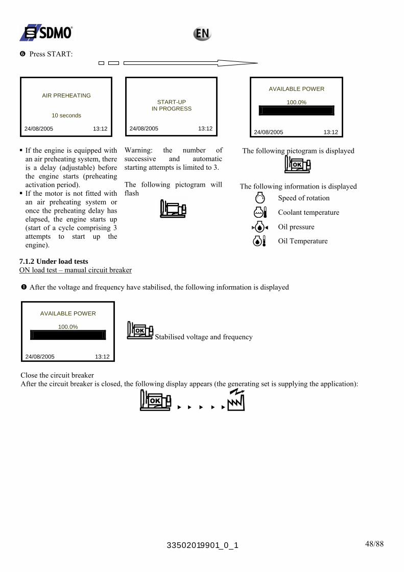
Press START:
AIR PREHEATING
10 seconds
24/08/2005 13:12
If the engine is equipped with an air preheating system, there is a delay (adjustable) before the engine starts (preheating activation period).
If the motor is not fitted with an air preheating system or once the preheating delay has elapsed, the engine starts up (start of a cycle comprising 3 attempts to start up the engine).
START-UP IN PROGRESS
24/08/2005 13:12
Warning: the number of successive and automatic starting attempts is limited to 3. The following pictogram will flash
AVAILABLE POWER
100.0%
08/2005 13:12
24/
The following pictogram is displayed
The following information is displayed
Speed of rotation
Coolant temperature
Oil pressure Oil Temperature
7.1.2 Under load tests ON load test – manual circuit breaker
After the voltage and frequency have stabilised, the following information is displayed
AVAILABLE POWER
100.0%
24/08/2005 13:12
Stabilised voltage and frequency
Close the circuit breaker After the circuit breaker is closed, the following display appears (the generating set is supplying the application):
33502019901_0_1 49/88
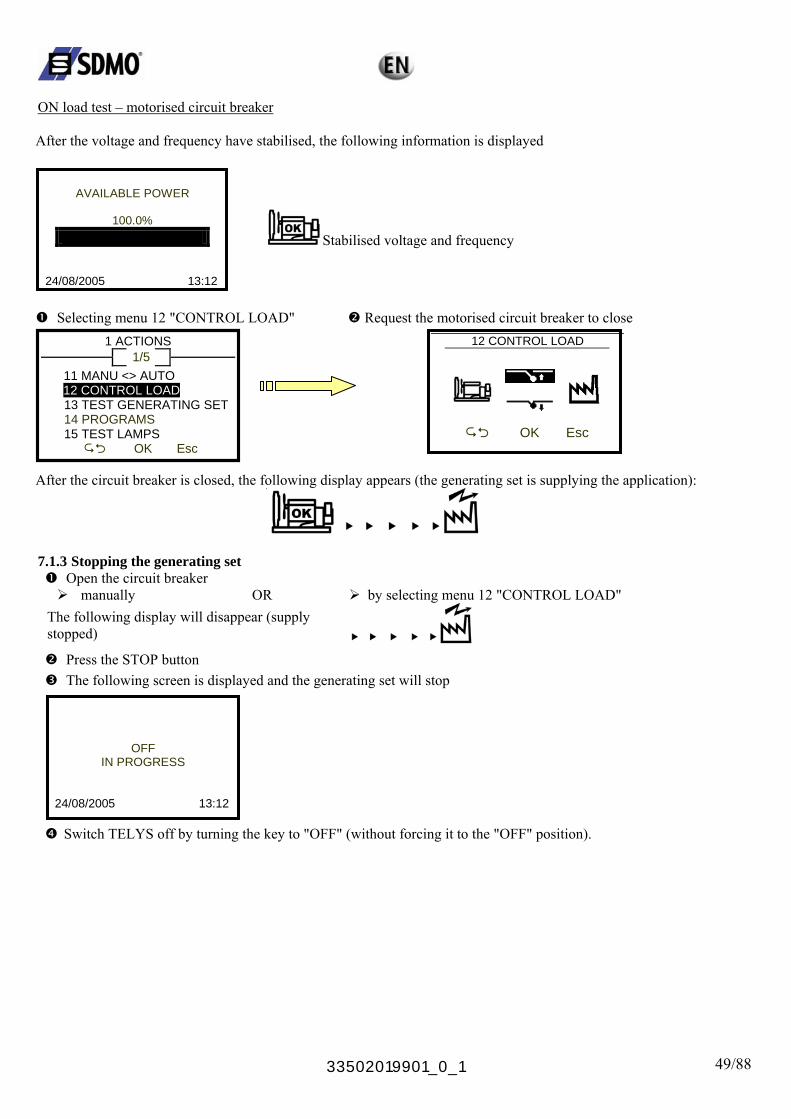
ON load test – motorised circuit breaker After the voltage and frequency have stabilised, the following information is displayed
AVAILABLE POWER
100.0%
24/08/2005 13:12
Stabilised voltage and frequency
Selecting menu 12 "CONTROL LOAD" Request the motorised circuit breaker to close 12 CONTROL LOAD 1 ACTIONS
1/5
11 MANU <> AUTO
112 CONTROL LOAD
3 TEST GENERATING SET
15 TEST LAMPS
OK Esc 14 PROGRAMS
OK Esc After the circuit breaker is closed, the following display appears (the generating set is supplying the application):
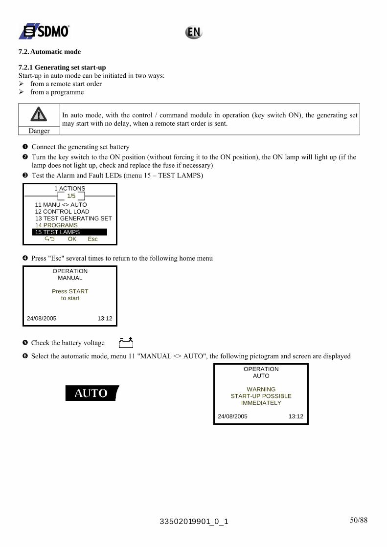
7.1.3 Stopping the generating set
Open the circuit breaker manually OR by selecting menu 12 "CONTROL LOAD"
The following display will disappear (supply stopped)
Press the STOP button The following screen is displayed and the generating set will stop
OFF IN PROGRESS
24/08/2005 13:12
Switch TELYS off by turning the key to "OFF" (without forcing it to the "OFF" position).
33502019901_0_1 50/88
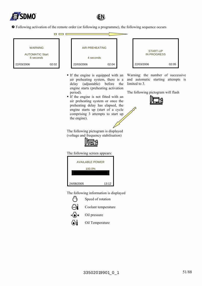
7.2. Automatic mode 7.2.1 Generating set start-up Start-up in auto mode can be initiated in two ways:
from a remote start order from a programme
In auto mode, with the control / command module in operation (key switch ON), the generating set may start with no delay, when a remote start order is sent.
Danger
Connect the generating set battery Turn the key switch to the ON position (without forcing it to the ON position), the ON lamp will light up (if the lamp does not light up, check and replace the fuse if necessary) Test the Alarm and Fault LEDs (menu 15 – TEST LAMPS)
1 ACTIONS 1/5
11 MANU <> AUTO 12 CONTROL LOAD
13 TEST GENERATING SET
14 PROGRAMS 15 TEST LAMPS
OK Esc
Press "Esc" several times to return to the following home menu
OPERATION MANUAL
Press START
to start 24/08/2005 13:12
Check the battery voltage
Select the automatic mode, menu 11 "MANUAL <> AUTO", the following pictogram and screen are displayed
OPERATION AUTO
WARNING
START-UP POSSIBLE IMMEDIATELY
24/08/2005 13:12
33502019901_0_1 51/88
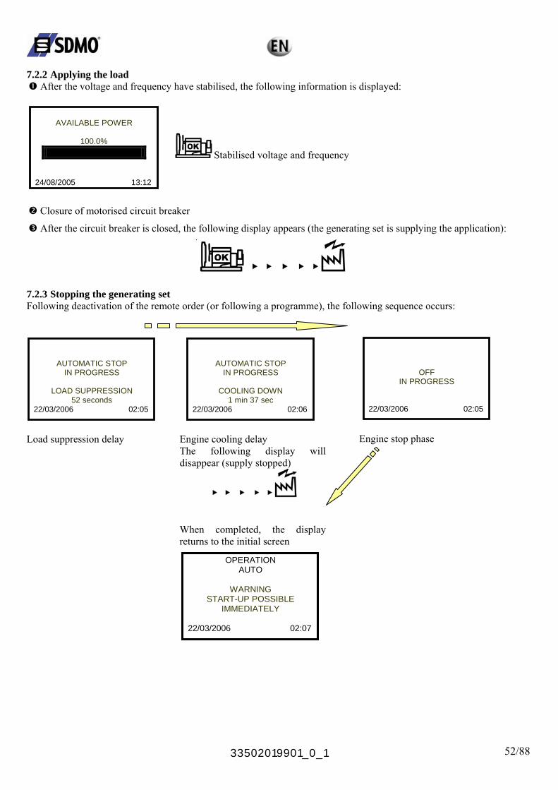
Following activation of the remote order (or following a programme), the following sequence occurs
WARNING
AUTOMATIC Start
6 seconds
22/03/2006 02:02
AIR PREHEATING
4 seconds
22/03/2006 02:04
If the engine is equipped with an air preheating system, there is a delay (adjustable) before the engine starts (preheating activation period).
If the engine is not fitted with an air preheating system or once the preheating delay has elapsed, the engine starts up (start of a cycle comprising 3 attempts to start up the engine).
START-UP IN PROGRESS
22/03/2006 02:05
Warning: the number of successive and automatic starting attempts is limited to 3. The following pictogram will flash
The following pictogram is displayed (voltage and frequency stabilisation)
The following screen appears:
AVAILABLE POWER
100.0%
24/08/2005 13:12
The following information is displayed
Speed of rotation
Coolant temperature
Oil pressure
Oil Temperature
33502019901_0_1 52/88
7.2.2 Applying the load
After the voltage and frequency have stabilised, the following information is displayed:
AVAILABLE POWER
100.0%
24/08/2005 13:12
Stabilised voltage and frequency
Closure of motorised circuit breaker
After the circuit breaker is closed, the following display appears (the generating set is supplying the application):
7.2.3 Stopping the generating set Following deactivation of the remote order (or following a programme), the following sequence occurs:
AUTOMATIC STOP IN PROGRESS
LOAD SUPPRESSION
52 seconds 22/03/2006 02:05
Load suppression delay
AUTOMATIC STOP IN PROGRESS
COOLING DOWN
1 min 37 sec 22/03/2006 02:06
OFF IN PROGRESS
22/03/2006 02:05
Engine stop phase
Engine cooling delay The following display will disappear (supply stopped)
When completed, the display returns to the initial screen
OPERATION AUTO
WARNING START-UP POSSIBLE
IMMEDIATELY 22/03/2006 02:07

33502019901_0_1 53/88
8. Fault finding
Problem Probable causes Remedial action Faulty module supply fuse Check and replace the fuse No LED displays and no
screen display Faulty battery Check and replace the battery if necessary 9. Maintenance 9.1. Replacing the fuse
Use a suitable screwdriver or your hand to turn the cap anti-clockwise until it can be removed. Remove and replace the fuse (use a fuse of the same size and rating). Refit the cap in the reverse order to removal.
33502019901_0_1 54/88
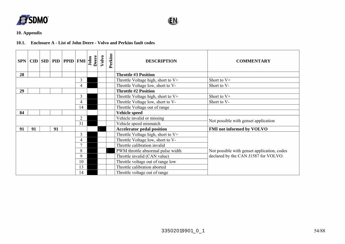
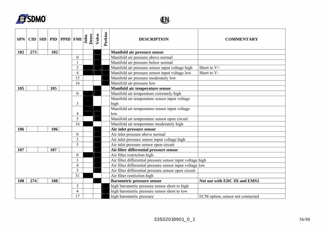
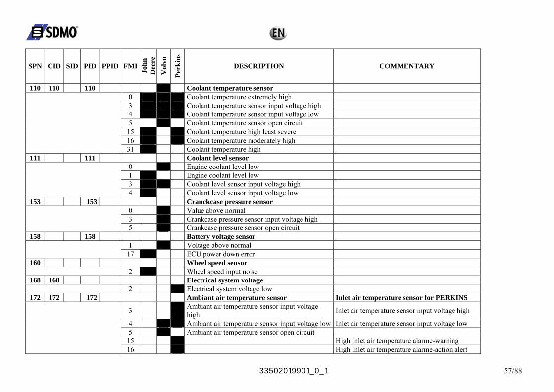
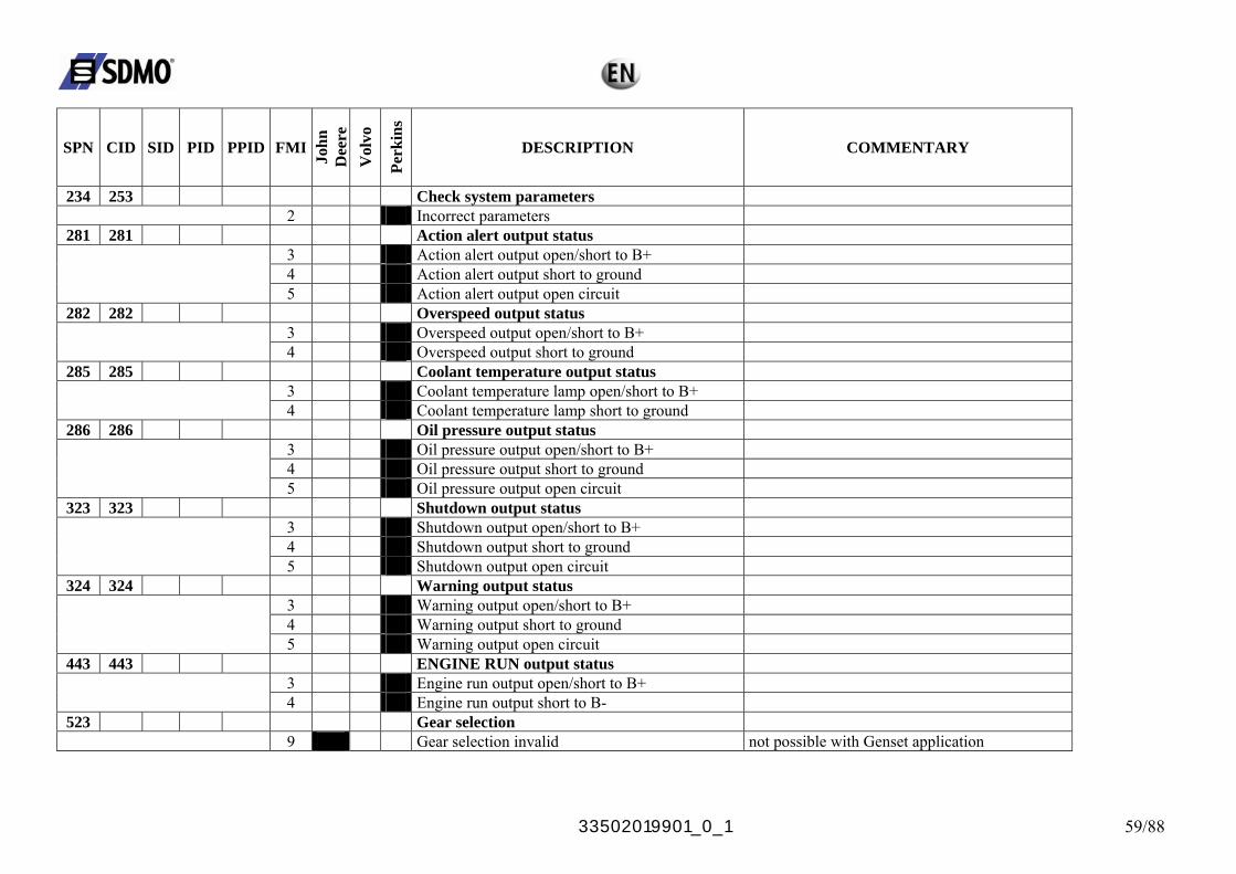
10. Appendix 10.1. Enclosure A - List of John Deere - Volvo and Perkins fault codes
SPN CID SID PID PPID FMI
John
D
eere
V
olvo
Perk
ins
DESCRIPTION COMMENTARY
28 Throttle #3 Position 3 Throttle Voltage high, short to V+ Short to V+
4 Throttle Voltage low, short to V- Short to V- 29 Throttle #2 Position
3 Throttle Voltage high, short to V+ Short to V+ 4 Throttle Voltage low, short to V- Short to V-
14 Throttle Voltage out of range 84 Vehicle speed
2 Vehicle invalid or missing 31 Vehicle speed mismatch Not possible with genset application
91 91 91 Accelerator pedal position FMI not informed by VOLVO 3 Throttle Voltage high, short to V+ 4 Throttle Voltage low, short to V- 7 Throttle calibration invalid 8 PWM throttle abnormal pulse width 9 Throttle invalid (CAN value)
10 Throttle voltage out of range low 13 Throttle calibration aborted
14 Throttle voltage out of range
Not possible with genset application, codes declared by the CAN J1587 for VOLVO.

33502019901_0_1 55/88
SPN CID SID PID PPID FMI
John
D
eere
V
olvo
Perk
ins
DESCRIPTION COMMENTARY
94 94 Fuel rail pressure sensor 1 Fuel supply pressure extremely low 3 Fuel rail pressure input voltage high Short to V+ 4 Fuel rail pressure input voltage low Short to V- 5 Fuel rail pressure sensor open circuit
10 Fuel rail pressure lost detected 13 Fuel rail pressure higher than expected 16 Fuel supply pressure moderately high 17 Fuel rail pressure not developped
18 Fuel supply pressure moderately low 97 97 Water in fuel sensor
0 Water in fuel continuously detected 3 Water in fuel input voltage high Short to V+ 4 Water in fuel input voltage low Short to V-
16 Water in fuel detected 31 Water in fuel detected
98 98 Oil level sensor 1 Oil level value below normal 3 Oil level sensor input voltage high Short to V+ 4 Oil level sensor input voltage low Short to V-
5 Oil level sensor open circuit 100 100 100 Oil pressure sensor
1 Engine oil pressure extremely low 3 Oil pressure sensor input voltage high Short to V+ 4 Oil pressure sensor input voltage low Short to V- 5 Oil pressure sensor open circuit
17 Engine oil pressure low 18 Engine oil pressure moderately low
33502019901_0_1 56/88
SPN CID SID PID PPID FMI
John
D
eere
V
olvo
Perk
ins
DESCRIPTION COMMENTARY
102 273 102 Manifold air pressure sensor 0 Manifold air pressure above normal 1 Manifold air pressure below normal 3 Manifold air pressure sensor input voltage high Short to V+ 4 Manifold air pressure sensor input voltage low Short to V-
15 Manifold air pressure moderately low 16 Manifold air pressure low
105 105 Manifold air temperature sensor 0 Manifold air temperature extremely high
3 Manifold air temperature sensor input voltage high
4 Manifold air temperature sensor input voltage low
5 Manifold air temperature sensor open circuit 16 Manifold air temperature moderately high
106 106 Air inlet pressure sensor 0 Air inlet pressure above normal 3 Air inlet pressure sensor input voltage high
5 Air inlet pressure sensor open circuit 107 107 Ait filter differential pressure sensor
0 Air filter restriction high 3 Air filter differential pressure sensor input voltage high 4 Air filter differential pressure sensor input voltage low 5 Air filter differential pressure sensor open circuit
31 Air filter restriction high 108 274 108 Barometric pressure sensor Not use with EDC III and EMS2
3 high barometric pressure sensor short to high 4 high barometric pressure sensor short to low
17 high barometric pressure ECM option, sensor not connected
33502019901_0_1 57/88
SPN CID SID PID PPID FMI
John
D
eere
V
olvo
Perk
ins
DESCRIPTION COMMENTARY
110 110 110 Coolant temperature sensor 0 Coolant temperature extremely high 3 Coolant temperature sensor input voltage high 4 Coolant temperature sensor input voltage low 5 Coolant temperature sensor open circuit
15 Coolant temperature high least severe 16 Coolant temperature moderately high
31 Coolant temperature high 111 111 Coolant level sensor
0 Engine coolant level low 1 Engine coolant level low 3 Coolant level sensor input voltage high
4 Coolant level sensor input voltage low 153 153 Cranckcase pressure sensor
0 Value above normal 3 Crankcase pressure sensor input voltage high
5 Crankcase pressure sensor open circuit 158 158 Battery voltage sensor
1 Voltage above normal 17 ECU power down error
160 Wheel speed sensor 2 Wheel speed input noise
168 168 Electrical system voltage 2 Electrical system voltage low
172 172 172 Ambiant air temperature sensor Inlet air temperature sensor for PERKINS
3 Ambiant air temperature sensor input voltage high Inlet air temperature sensor input voltage high
4 Ambiant air temperature sensor input voltage low Inlet air temperature sensor input voltage low 5 Ambiant air temperature sensor open circuit
15 High Inlet air temperature alarme-warning 16 High Inlet air temperature alarme-action alert

33502019901_0_1 58/88
SPN CID SID PID PPID FMI
John
D
eere
V
olvo
Perk
ins
DESCRIPTION COMMENTARY
174 174 Fuel temperature sensor 0 Fuel temperature high most severe 3 Fuel temperature sensor input voltage high 4 Fuel temperature sensor input voltage low
15 Fuel temperature high 16 Fuel temperature high moderately high
31 Fuel temperature sensor faulty 175 175 Oil temperature sensor
0 Oil temperature extremely high 3 Oil temperature sensor input voltage high 4 Oil temperature sensor input voltage low
5 Oil temperature sensor open circuit 177 Transmission oil temperature sensor
9 Transmission oil temperature invalid not possible with Genset application 189 Rated engine speed
0 Engine speed derated 31 Engine speed derated
190 190 190 Engine speed sensor 0 Overspeed extreme 2 Engine speed sensor data intermittent 9 Engine speed sensor abnormal update
11 Engine speed sensor signal lost 12 Engine speed sensor signal lost 15 Overspeed
16 Overspeed moderate 228 261 Speed sensor calibration
13 Engine timing abnormal calibration 252 252 Software
11 Incorrect engine software
33502019901_0_1 59/88
SPN CID SID PID PPID FMI
John
D
eere
V
olvo
Perk
ins
DESCRIPTION COMMENTARY
234 253 Check system parameters 2 Incorrect parameters
281 281 Action alert output status 3 Action alert output open/short to B+ 4 Action alert output short to ground
5 Action alert output open circuit 282 282 Overspeed output status
3 Overspeed output open/short to B+ 4 Overspeed output short to ground
285 285 Coolant temperature output status 3 Coolant temperature lamp open/short to B+
4 Coolant temperature lamp short to ground 286 286 Oil pressure output status
3 Oil pressure output open/short to B+ 4 Oil pressure output short to ground
5 Oil pressure output open circuit 323 323 Shutdown output status
3 Shutdown output open/short to B+ 4 Shutdown output short to ground
5 Shutdown output open circuit 324 324 Warning output status
3 Warning output open/short to B+ 4 Warning output short to ground
5 Warning output open circuit 443 443 ENGINE RUN output status
3 Engine run output open/short to B+ 4 Engine run output short to B-
523 Gear selection 9 Gear selection invalid not possible with Genset application
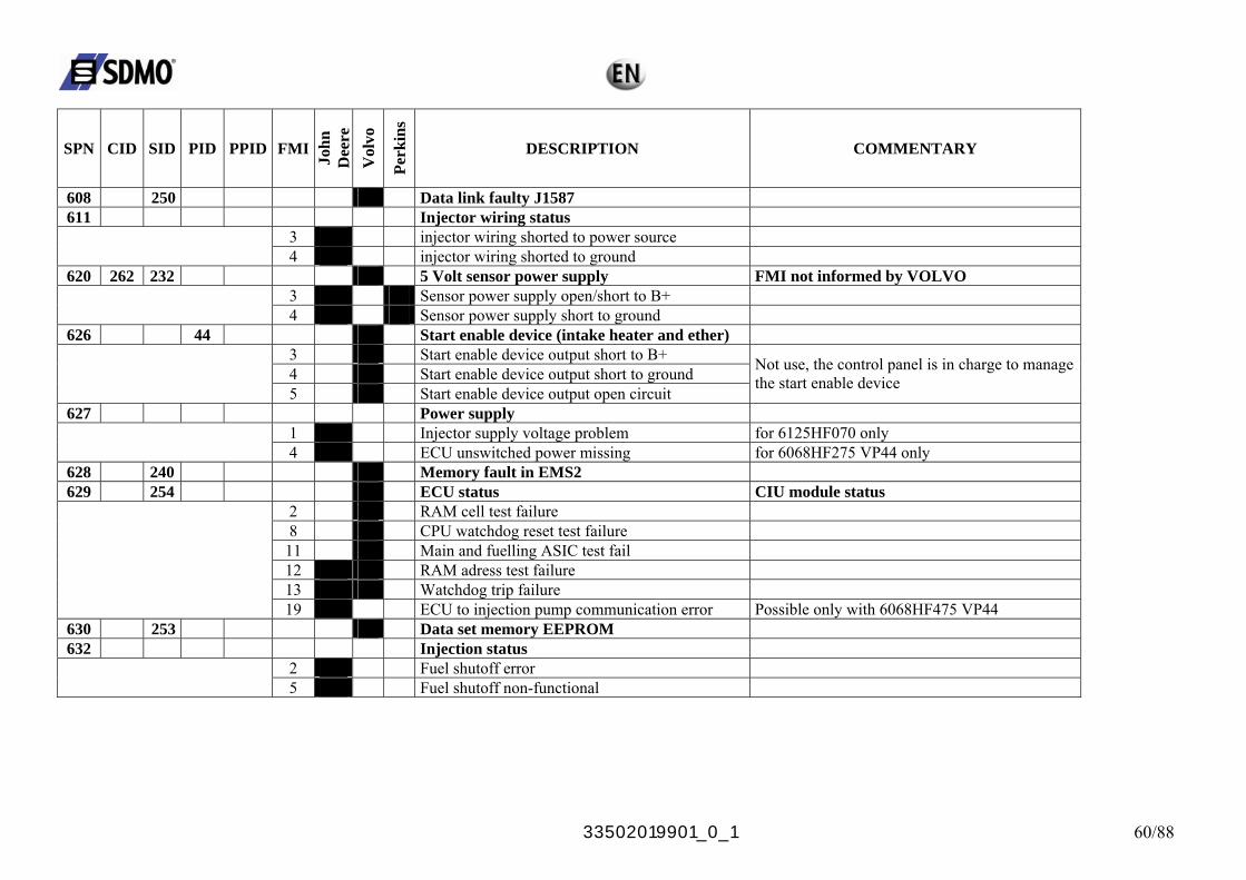
33502019901_0_1 60/88
SPN CID SID PID PPID FMI
John
D
eere
V
olvo
Perk
ins
DESCRIPTION COMMENTARY
608 250 Data link faulty J1587 611 Injector wiring status
3 injector wiring shorted to power source 4 injector wiring shorted to ground
620 262 232 5 Volt sensor power supply FMI not informed by VOLVO 3 Sensor power supply open/short to B+
4 Sensor power supply short to ground 626 44 Start enable device (intake heater and ether)
3 Start enable device output short to B+ 4 Start enable device output short to ground
5 Start enable device output open circuit
Not use, the control panel is in charge to manage the start enable device
627 Power supply 1 Injector supply voltage problem for 6125HF070 only
4 ECU unswitched power missing for 6068HF275 VP44 only 628 240 Memory fault in EMS2 629 254 ECU status CIU module status
2 RAM cell test failure 8 CPU watchdog reset test failure
11 Main and fuelling ASIC test fail 12 RAM adress test failure 13 Watchdog trip failure
19 ECU to injection pump communication error Possible only with 6068HF475 VP44 630 253 Data set memory EEPROM 632 Injection status
2 Fuel shutoff error 5 Fuel shutoff non-functional
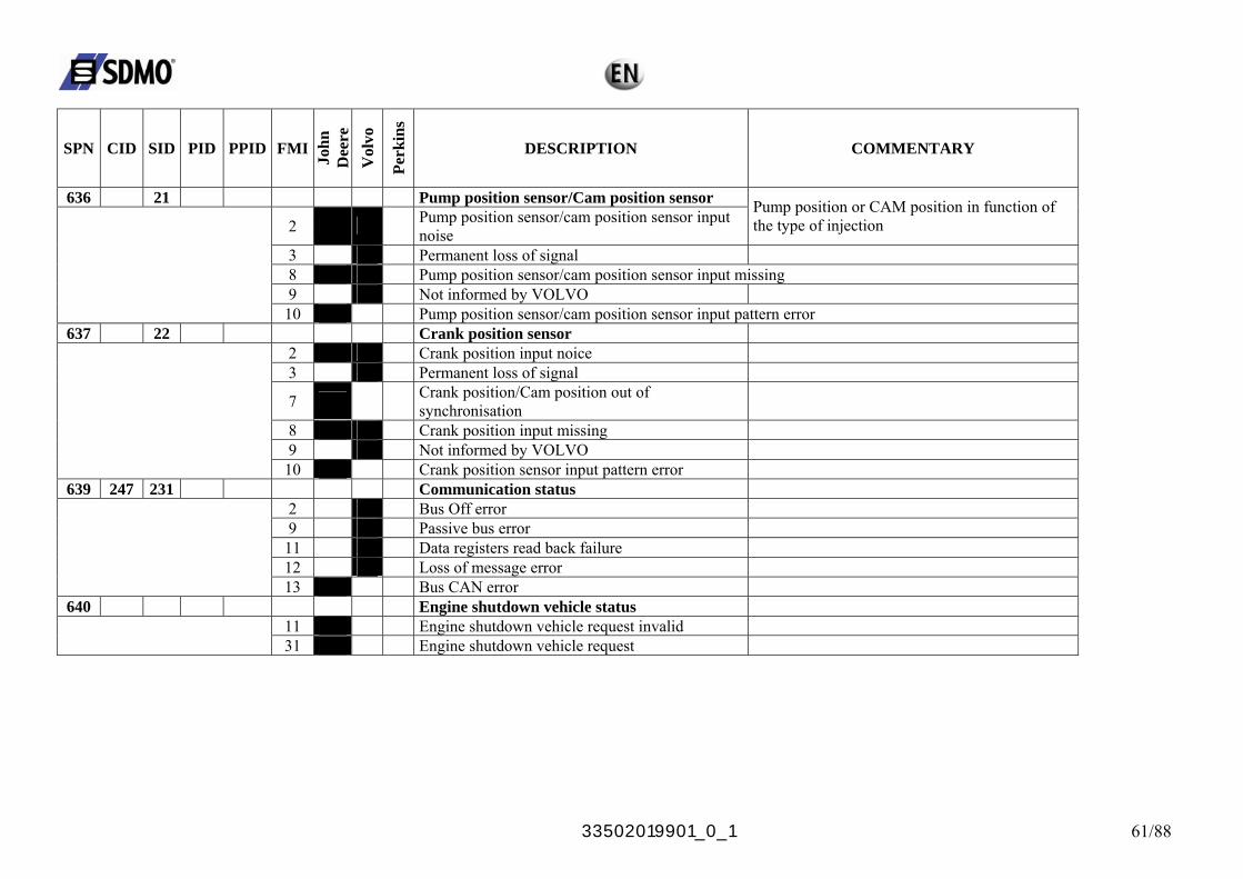
33502019901_0_1 61/88
SPN CID SID PID PPID FMI
John
D
eere
V
olvo
Perk
ins
DESCRIPTION COMMENTARY
636 21 Pump position sensor/Cam position sensor
2 Pump position sensor/cam position sensor input noise
Pump position or CAM position in function of the type of injection
3 Permanent loss of signal 8 Pump position sensor/cam position sensor input missing 9 Not informed by VOLVO
10 Pump position sensor/cam position sensor input pattern error 637 22 Crank position sensor
2 Crank position input noice 3 Permanent loss of signal
7 Crank position/Cam position out of synchronisation
8 Crank position input missing 9 Not informed by VOLVO
10 Crank position sensor input pattern error 639 247 231 Communication status
2 Bus Off error 9 Passive bus error
11 Data registers read back failure 12 Loss of message error
13 Bus CAN error 640 Engine shutdown vehicle status
11 Engine shutdown vehicle request invalid 31 Engine shutdown vehicle request
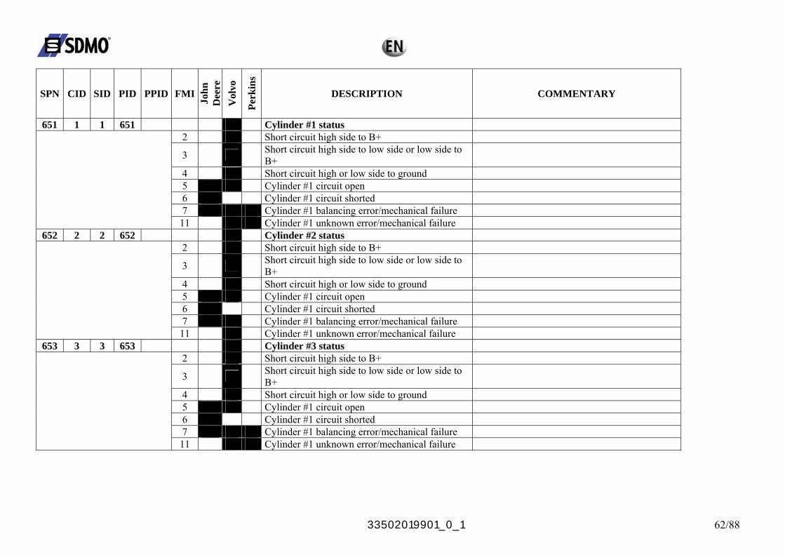
33502019901_0_1 62/88
SPN CID SID PID PPID FMI
John
D
eere
V
olvo
Perk
ins
DESCRIPTION COMMENTARY
651 1 1 651 Cylinder #1 status 2 Short circuit high side to B+
3 Short circuit high side to low side or low side to B+
4 Short circuit high or low side to ground 5 Cylinder #1 circuit open 6 Cylinder #1 circuit shorted 7 Cylinder #1 balancing error/mechanical failure
11 Cylinder #1 unknown error/mechanical failure 652 2 2 652 Cylinder #2 status
2 Short circuit high side to B+
3 Short circuit high side to low side or low side to B+
4 Short circuit high or low side to ground 5 Cylinder #1 circuit open 6 Cylinder #1 circuit shorted 7 Cylinder #1 balancing error/mechanical failure
11 Cylinder #1 unknown error/mechanical failure 653 3 3 653 Cylinder #3 status
2 Short circuit high side to B+
3 Short circuit high side to low side or low side to B+
4 Short circuit high or low side to ground 5 Cylinder #1 circuit open 6 Cylinder #1 circuit shorted 7 Cylinder #1 balancing error/mechanical failure
11 Cylinder #1 unknown error/mechanical failure
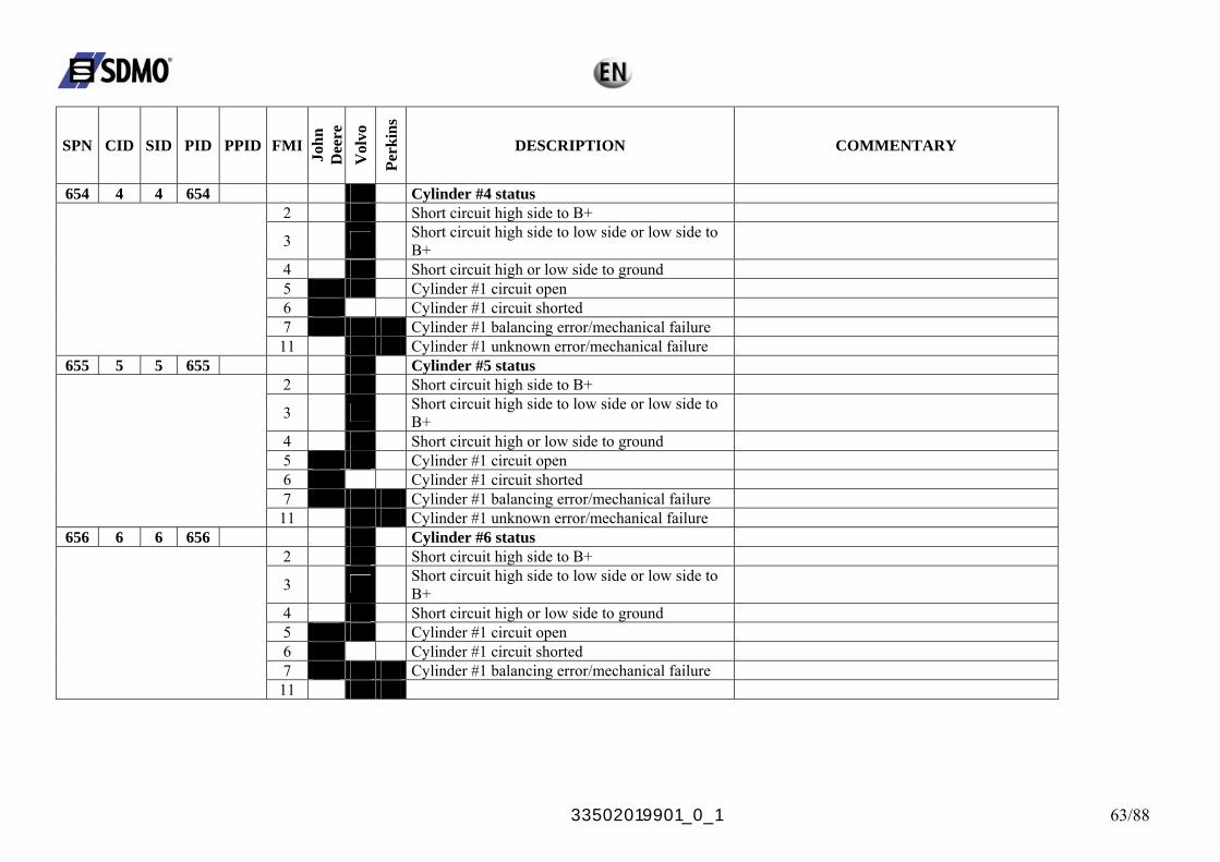
33502019901_0_1 63/88
SPN CID SID PID PPID FMI
John
D
eere
V
olvo
Perk
ins
DESCRIPTION COMMENTARY
654 4 4 654 Cylinder #4 status 2 Short circuit high side to B+
3 Short circuit high side to low side or low side to B+
4 Short circuit high or low side to ground 5 Cylinder #1 circuit open 6 Cylinder #1 circuit shorted 7 Cylinder #1 balancing error/mechanical failure
11 Cylinder #1 unknown error/mechanical failure 655 5 5 655 Cylinder #5 status
2 Short circuit high side to B+
3 Short circuit high side to low side or low side to B+
4 Short circuit high or low side to ground 5 Cylinder #1 circuit open 6 Cylinder #1 circuit shorted 7 Cylinder #1 balancing error/mechanical failure
11 Cylinder #1 unknown error/mechanical failure 656 6 6 656 Cylinder #6 status
2 Short circuit high side to B+
3 Short circuit high side to low side or low side to B+
4 Short circuit high or low side to ground 5 Cylinder #1 circuit open 6 Cylinder #1 circuit shorted 7 Cylinder #1 balancing error/mechanical failure
11
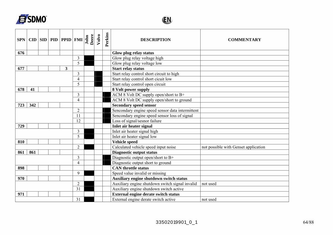
33502019901_0_1 64/88
SPN CID SID PID PPID FMI
John
D
eere
V
olvo
Perk
ins
DESCRIPTION COMMENTARY
676 Glow plug relay status 3 Glow plug relay voltage high
5 Glow plug relay voltage low 677 3 Start relay status
3 Start relay control short circuit to high 4 Start relay control short cicuit low
5 Start relay control open circuit 678 41 8 Volt power supply
3 ACM 8 Volt DC supply open/short to B+ 4 ACM 8 Volt DC supply open/short to ground
723 342 Secondary speed sensor 2 Sencondary engine speed sensor data intermittent
11 Sencondary engine speed sensor loss of signal 12 Loss of signal/sesnor failure
729 Inlet air heater signal 3 Inlet air heater signal high
5 Inlet air heater signal low 810 Vehicle speed
2 Calculated vehicle speed input noise not possible with Genset application 861 861 Diagnostic output status
3 Diagnostic output open/short to B+ 4 Diagnostic output short to ground
898 CAN throttle status 9 Speed value invalid or missing
970 Auxiliary engine shutdown switch status 2 Auxiliary engine shutdown switch signal invalid not used
31 Auxiliary engine shutdown switch active 971 External engine derate switch status
31 External engine derate switch active not used
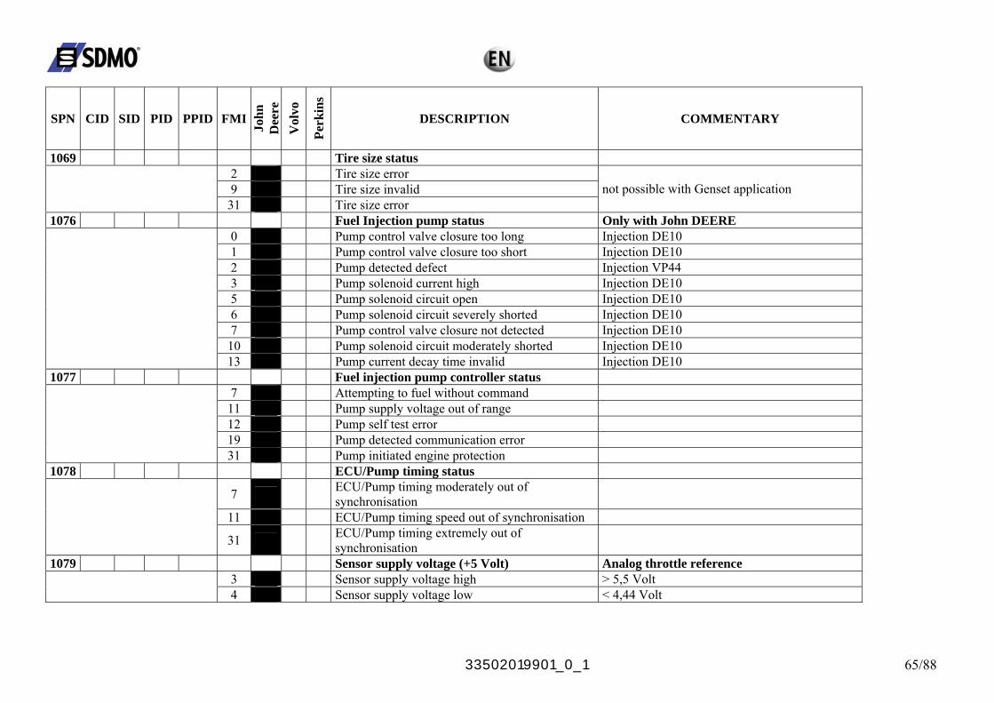
33502019901_0_1 65/88
SPN CID SID PID PPID FMI
John
D
eere
V
olvo
Perk
ins
DESCRIPTION COMMENTARY
1069 Tire size status 2 Tire size error 9 Tire size invalid
31 Tire size error not possible with Genset application
1076 Fuel Injection pump status Only with John DEERE 0 Pump control valve closure too long Injection DE10 1 Pump control valve closure too short Injection DE10 2 Pump detected defect Injection VP44 3 Pump solenoid current high Injection DE10 5 Pump solenoid circuit open Injection DE10 6 Pump solenoid circuit severely shorted Injection DE10 7 Pump control valve closure not detected Injection DE10
10 Pump solenoid circuit moderately shorted Injection DE10 13 Pump current decay time invalid Injection DE10
1077 Fuel injection pump controller status 7 Attempting to fuel without command
11 Pump supply voltage out of range 12 Pump self test error 19 Pump detected communication error
31 Pump initiated engine protection 1078 ECU/Pump timing status
7 ECU/Pump timing moderately out of synchronisation
11 ECU/Pump timing speed out of synchronisation
31 ECU/Pump timing extremely out of synchronisation
1079 Sensor supply voltage (+5 Volt) Analog throttle reference 3 Sensor supply voltage high > 5,5 Volt
4 Sensor supply voltage low < 4,44 Volt
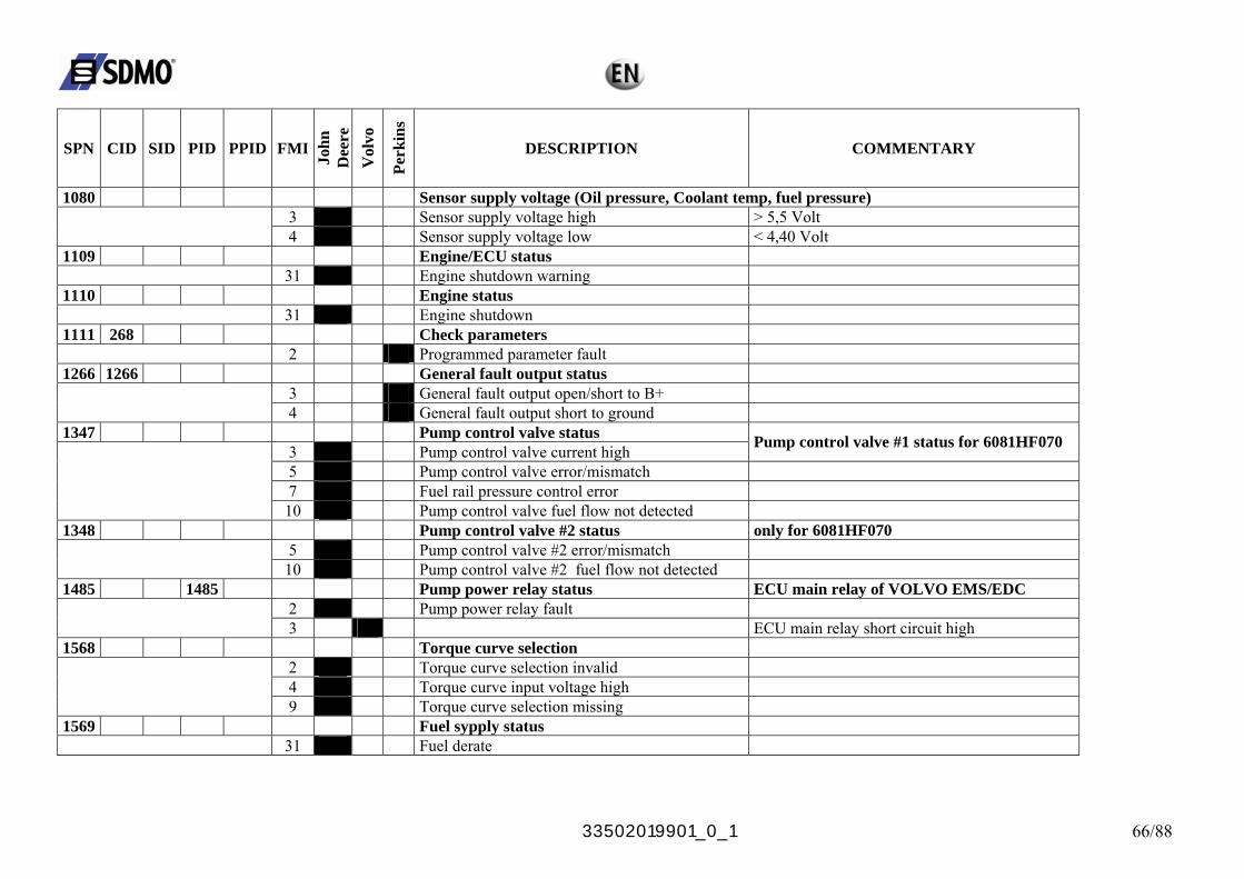
33502019901_0_1 66/88
SPN CID SID PID PPID FMI
John
D
eere
V
olvo
Perk
ins
DESCRIPTION COMMENTARY
1080 Sensor supply voltage (Oil pressure, Coolant temp, fuel pressure) 3 Sensor supply voltage high > 5,5 Volt
4 Sensor supply voltage low < 4,40 Volt 1109 Engine/ECU status
31 Engine shutdown warning 1110 Engine status
31 Engine shutdown 1111 268 Check parameters
2 Programmed parameter fault 1266 1266 General fault output status
3 General fault output open/short to B+ 4 General fault output short to ground
1347 Pump control valve status 3 Pump control valve current high Pump control valve #1 status for 6081HF070
5 Pump control valve error/mismatch 7 Fuel rail pressure control error
10 Pump control valve fuel flow not detected 1348 Pump control valve #2 status only for 6081HF070
5 Pump control valve #2 error/mismatch 10 Pump control valve #2 fuel flow not detected
1485 1485 Pump power relay status ECU main relay of VOLVO EMS/EDC 2 Pump power relay fault
3 ECU main relay short circuit high 1568 Torque curve selection
2 Torque curve selection invalid 4 Torque curve input voltage high
9 Torque curve selection missing 1569 Fuel sypply status
31 Fuel derate
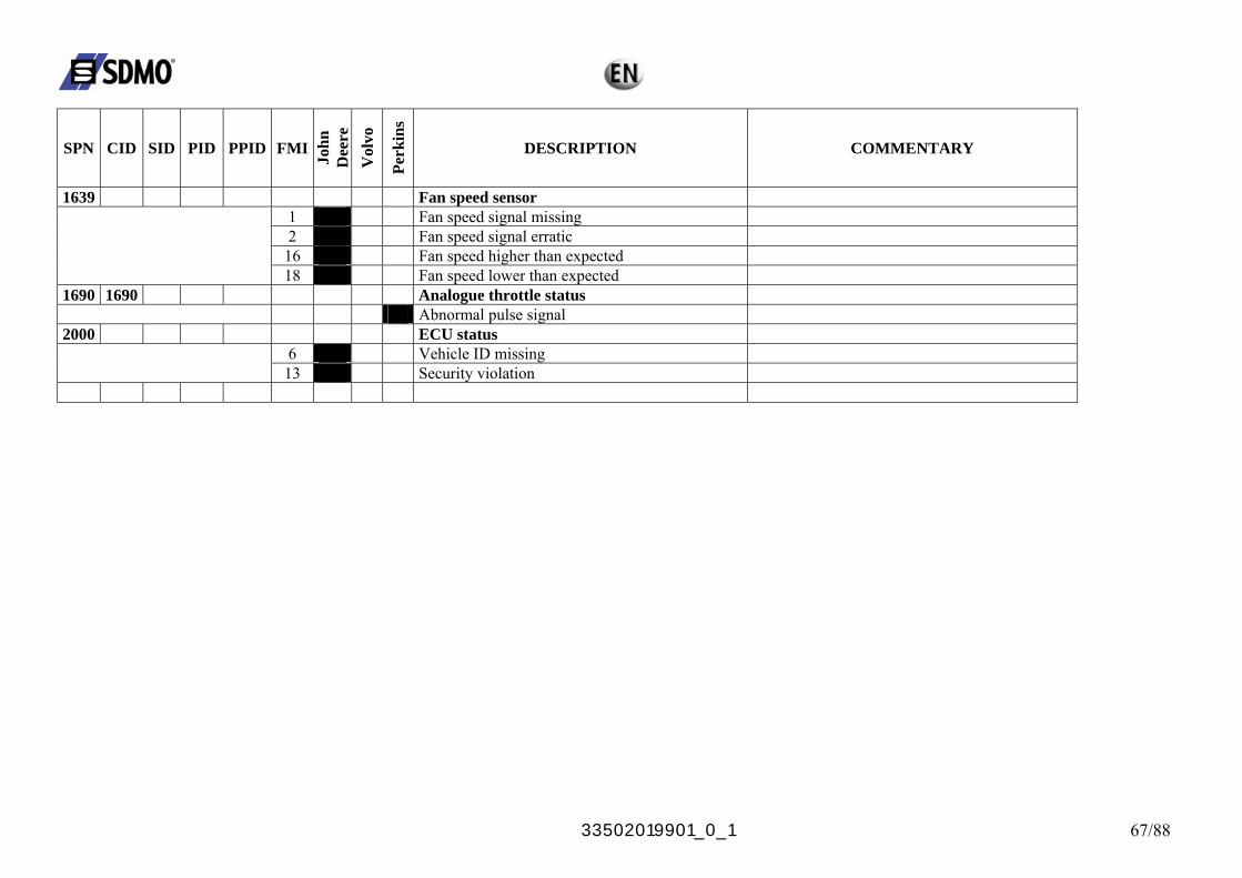
33502019901_0_1 67/88
SPN CID SID PID PPID FMI
John
D
eere
V
olvo
Perk
ins
DESCRIPTION COMMENTARY
1639 Fan speed sensor 1 Fan speed signal missing 2 Fan speed signal erratic
16 Fan speed higher than expected 18 Fan speed lower than expected
1690 1690 Analogue throttle status Abnormal pulse signal
2000 ECU status 6 Vehicle ID missing
13 Security violation
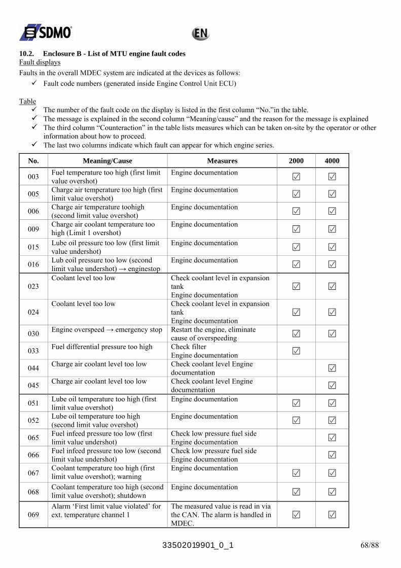
33502019901_0_1 68/88
10.2. Enclosure B - List of MTU engine fault codes Fault displays Faults in the overall MDEC system are indicated at the devices as follows:
Fault code numbers (generated inside Engine Control Unit ECU) Table
The number of the fault code on the display is listed in the first column “No.”in the table. The message is explained in the second column “Meaning/cause” and the reason for the message is explained The third column “Counteraction” in the table lists measures which can be taken on-site by the operator or other
information about how to proceed. The last two columns indicate which fault can appear for which engine series.
No. Meaning/Cause Measures 2000 4000
003 Fuel temperature too high (first limit value overshot)
Engine documentation
005 Charge air temperature too high (first limit value overshot)
Engine documentation
006 Charge air temperature toohigh (second limit value overshot)
Engine documentation
009 Charge air coolant temperature too high (Limit 1 overshot)
Engine documentation
015 Lube oil pressure too low (first limit value undershot)
Engine documentation
016 Lub eoil pressure too low (second limit value undershot) → enginestop
Engine documentation
023 Coolant level too low Check coolant level in expansion
tank Engine documentation
024 Coolant level too low Check coolant level in expansion
tank Engine documentation
030 Engine overspeed → emergency stop Restart the engine, eliminate cause of overspeeding
033 Fuel differential pressure too high Check filter Engine documentation
044 Charge air coolant level too low Check coolant level Engine documentation
045 Charge air coolant level too low Check coolant level Engine documentation
051 Lube oil temperature too high (first limit value overshot)
Engine documentation
052 Lube oil temperature too high (second limit value overshot)
Engine documentation
065 Fuel infeed pressure too low (first limit value undershot)
Check low pressure fuel side Engine documentation
066 Fuel infeed pressure too low (second limit value undershot)
Check low pressure fuel side Engine documentation
067 Coolant temperature too high (first limit value overshot); warning
Engine documentation
068 Coolant temperature too high (second limit value overshot); shutdown
Engine documentation
069 Alarm ‘First limit value violated’ for ext. temperature channel 1
The measured value is read in via the CAN. The alarm is handled in MDEC.
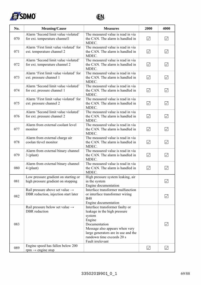
33502019901_0_1 69/88
No. Meaning/Cause Measures 2000 4000
070 Alarm ‘Second limit value violated’ for ext. temperature channel1
The measured value is read in via the CAN. The alarm is handled in MDEC.
071 Alarm ‘First limit value violated’ for ext. temperature channel 2
The measured value is read in via the CAN. The alarm is handled in MDEC.
072 Alarm ‘Second limit value violated’ for ext. temperature channel 2
The measured value is read in via the CAN. The alarm is handled in MDEC.
073 Alarm ‘First limit value violated’ for ext. pressure channel 1
The measured value is read in via the CAN. The alarm is handled in MDEC.
074 Alarm ‘Second limit value violated’ for ext. pressure channel 1
The measured value is read in via the CAN. The alarm is handled in MDEC.
075 Alarm ’First limit value violated’ for ext. pressure channel 2
The measured value is read in via the CAN. The alarm is handled in MDEC.
076 Alarm ’Second limit value violated’ for ext. pressure channel 2
The measured value is read in via the CAN. The alarm is handled in MDEC.
077 Alarm from external coolant level monitor
The measured value is read in via the CAN. The alarm is handled in MDEC.
078 Alarm from external charge air coolan tlevel monitor
The measured value is read in via the CAN. The alarm is handled in MDEC.
079 Alarm from external binary channel 3 (plant)
The measured value is read in via the CAN. The alarm is handled in MDEC.
080 Alarm from external binary channel 4 (plant)
The measured value is read in via the CAN. The alarm is handled in MDEC.
081 Low pressure gradient on starting or high pressure gradient on stopping
High pressure system leaking, air in the system Engine documentation
082
Rail pressure above set value → DBR reduction, injection start later
Interface transformer malfunction or interface transformer wiring B48 Engine documentation
083
Rail pressure below set value → DBR reduction
Interface transformer faulty or leakage in the high pressure system Engine Documentation Message also appears when very large generators are in use and the rundown time exceeds 20 s Fault irrelevant
089 Engine speed has fallen below 200 rpm → engine stop
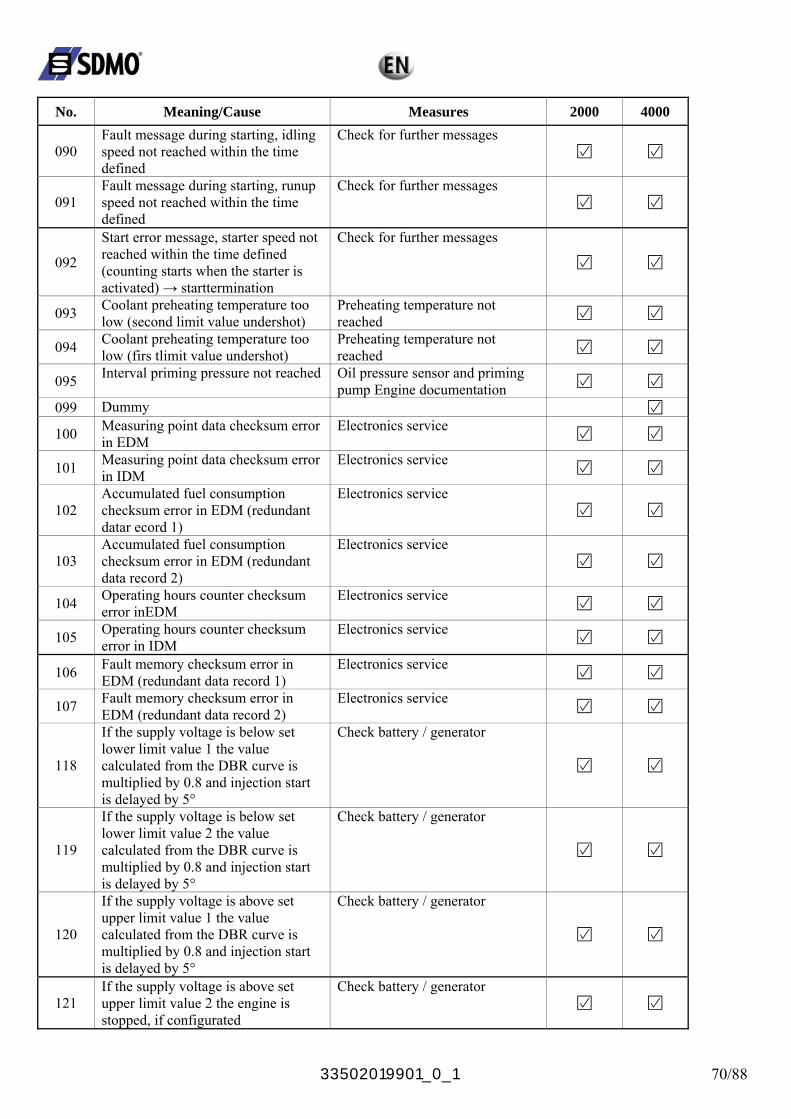
33502019901_0_1 70/88
No. Meaning/Cause Measures 2000 4000
090 Fault message during starting, idling speed not reached within the time defined
Check for further messages
091 Fault message during starting, runup speed not reached within the time defined
Check for further messages
092
Start error message, starter speed not reached within the time defined (counting starts when the starter is activated) → starttermination
Check for further messages
093 Coolant preheating temperature too low (second limit value undershot)
Preheating temperature not reached
094 Coolant preheating temperature too low (firs tlimit value undershot)
Preheating temperature not reached
095 Interval priming pressure not reached Oil pressure sensor and priming pump Engine documentation
099 Dummy
100 Measuring point data checksum error in EDM
Electronics service
101 Measuring point data checksum error in IDM
Electronics service
102 Accumulated fuel consumption checksum error in EDM (redundant datar ecord 1)
Electronics service
103 Accumulated fuel consumption checksum error in EDM (redundant data record 2)
Electronics service
104 Operating hours counter checksum error inEDM
Electronics service
105 Operating hours counter checksum error in IDM
Electronics service
106 Fault memory checksum error in EDM (redundant data record 1)
Electronics service
107 Fault memory checksum error in EDM (redundant data record 2)
Electronics service
118
If the supply voltage is below set lower limit value 1 the value calculated from the DBR curve is multiplied by 0.8 and injection start is delayed by 5°
Check battery / generator
119
If the supply voltage is below set lower limit value 2 the value calculated from the DBR curve is multiplied by 0.8 and injection start is delayed by 5°
Check battery / generator
120
If the supply voltage is above set upper limit value 1 the value calculated from the DBR curve is multiplied by 0.8 and injection start is delayed by 5°
Check battery / generator
121 If the supply voltage is above set upper limit value 2 the engine is stopped, if configurated
Check battery / generator
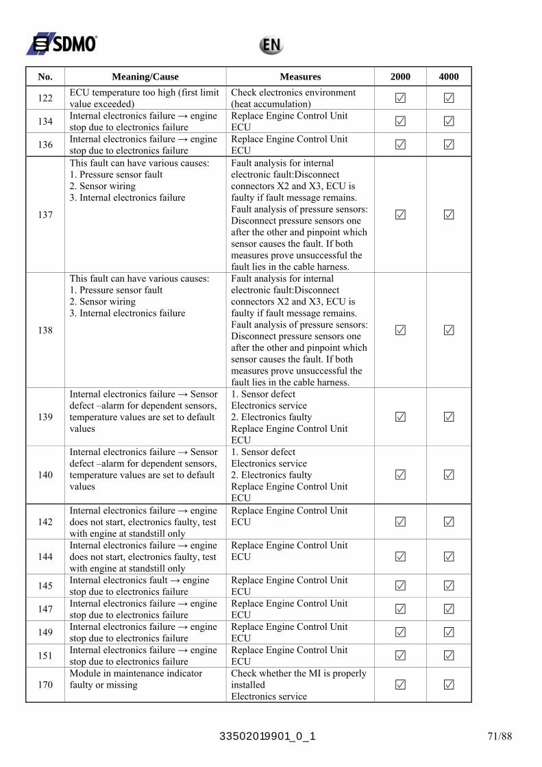
33502019901_0_1 71/88
No. Meaning/Cause Measures 2000 4000
122 ECU temperature too high (first limit value exceeded)
Check electronics environment (heat accumulation)
134 Internal electronics failure → engine stop due to electronics failure
Replace Engine Control Unit ECU
136 Internal electronics failure → engine stop due to electronics failure
Replace Engine Control Unit ECU
137
This fault can have various causes: 1. Pressure sensor fault 2. Sensor wiring 3. Internal electronics failure
Fault analysis for internal electronic fault:Disconnect connectors X2 and X3, ECU is faulty if fault message remains. Fault analysis of pressure sensors: Disconnect pressure sensors one after the other and pinpoint which sensor causes the fault. If both measures prove unsuccessful the fault lies in the cable harness.
138
This fault can have various causes: 1. Pressure sensor fault 2. Sensor wiring 3. Internal electronics failure
Fault analysis for internal electronic fault:Disconnect connectors X2 and X3, ECU is faulty if fault message remains. Fault analysis of pressure sensors: Disconnect pressure sensors one after the other and pinpoint which sensor causes the fault. If both measures prove unsuccessful the fault lies in the cable harness.
139
Internal electronics failure → Sensor defect –alarm for dependent sensors, temperature values are set to default values
1. Sensor defect Electronics service 2. Electronics faulty Replace Engine Control Unit ECU
140
Internal electronics failure → Sensor defect –alarm for dependent sensors, temperature values are set to default values
1. Sensor defect Electronics service 2. Electronics faulty Replace Engine Control Unit ECU
142 Internal electronics failure → engine does not start, electronics faulty, test with engine at standstill only
Replace Engine Control Unit ECU
144 Internal electronics failure → engine does not start, electronics faulty, test with engine at standstill only
Replace Engine Control Unit ECU
145 Internal electronics fault → engine stop due to electronics failure
Replace Engine Control Unit ECU
147 Internal electronics failure → engine stop due to electronics failure
Replace Engine Control Unit ECU
149 Internal electronics failure → engine stop due to electronics failure
Replace Engine Control Unit ECU
151 Internal electronics failure → engine stop due to electronics failure
Replace Engine Control Unit ECU
170 Module in maintenance indicator faulty or missing
Check whether the MI is properly installed Electronics service
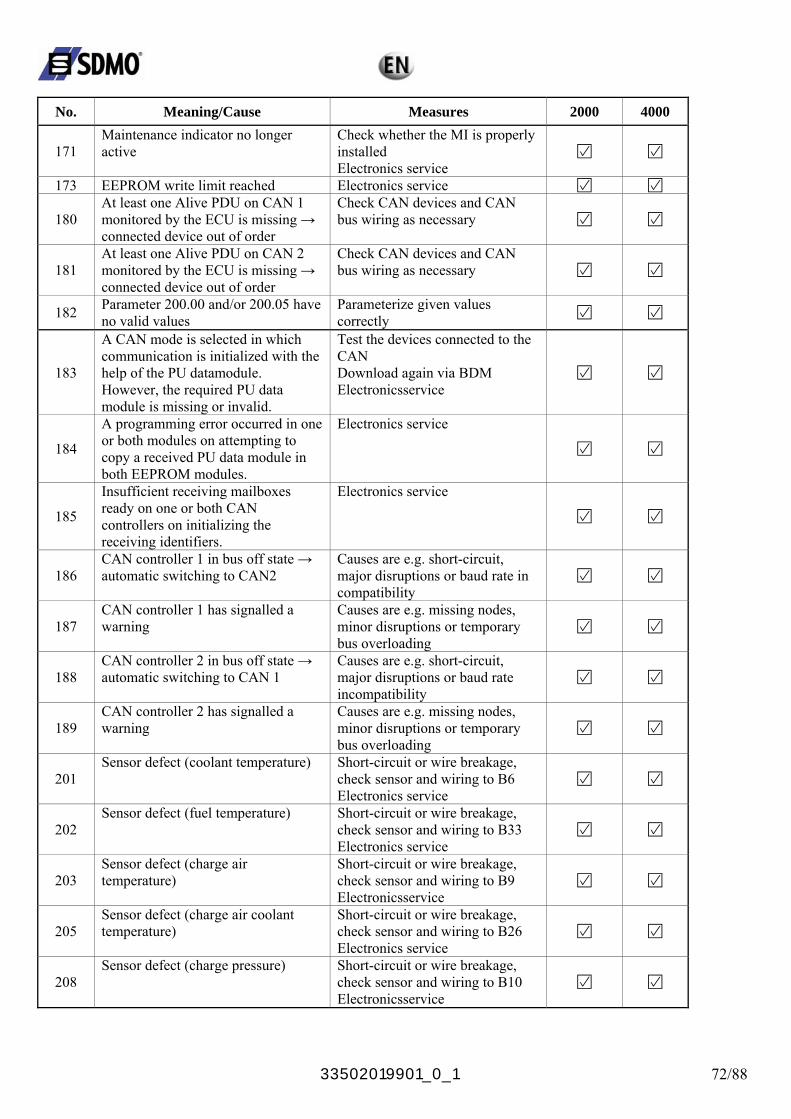
33502019901_0_1 72/88
No. Meaning/Cause Measures 2000 4000
171 Maintenance indicator no longer active
Check whether the MI is properly installed Electronics service
173 EEPROM write limit reached Electronics service
180 At least one Alive PDU on CAN 1 monitored by the ECU is missing → connected device out of order
Check CAN devices and CAN bus wiring as necessary
181 At least one Alive PDU on CAN 2 monitored by the ECU is missing → connected device out of order
Check CAN devices and CAN bus wiring as necessary
182 Parameter 200.00 and/or 200.05 have no valid values
Parameterize given values correctly
183
A CAN mode is selected in which communication is initialized with the help of the PU datamodule. However, the required PU data module is missing or invalid.
Test the devices connected to the CAN Download again via BDM Electronicsservice
184
A programming error occurred in one or both modules on attempting to copy a received PU data module in both EEPROM modules.
Electronics service
185
Insufficient receiving mailboxes ready on one or both CAN controllers on initializing the receiving identifiers.
Electronics service
186 CAN controller 1 in bus off state → automatic switching to CAN2
Causes are e.g. short-circuit, major disruptions or baud rate in compatibility
187 CAN controller 1 has signalled a warning
Causes are e.g. missing nodes, minor disruptions or temporary bus overloading
188 CAN controller 2 in bus off state → automatic switching to CAN 1
Causes are e.g. short-circuit, major disruptions or baud rate incompatibility
189 CAN controller 2 has signalled a warning
Causes are e.g. missing nodes, minor disruptions or temporary bus overloading
201 Sensor defect (coolant temperature) Short-circuit or wire breakage,
check sensor and wiring to B6 Electronics service
202 Sensor defect (fuel temperature) Short-circuit or wire breakage,
check sensor and wiring to B33 Electronics service
203 Sensor defect (charge air temperature)
Short-circuit or wire breakage, check sensor and wiring to B9 Electronicsservice
205 Sensor defect (charge air coolant temperature)
Short-circuit or wire breakage, check sensor and wiring to B26 Electronics service
208 Sensor defect (charge pressure) Short-circuit or wire breakage,
check sensor and wiring to B10 Electronicsservice
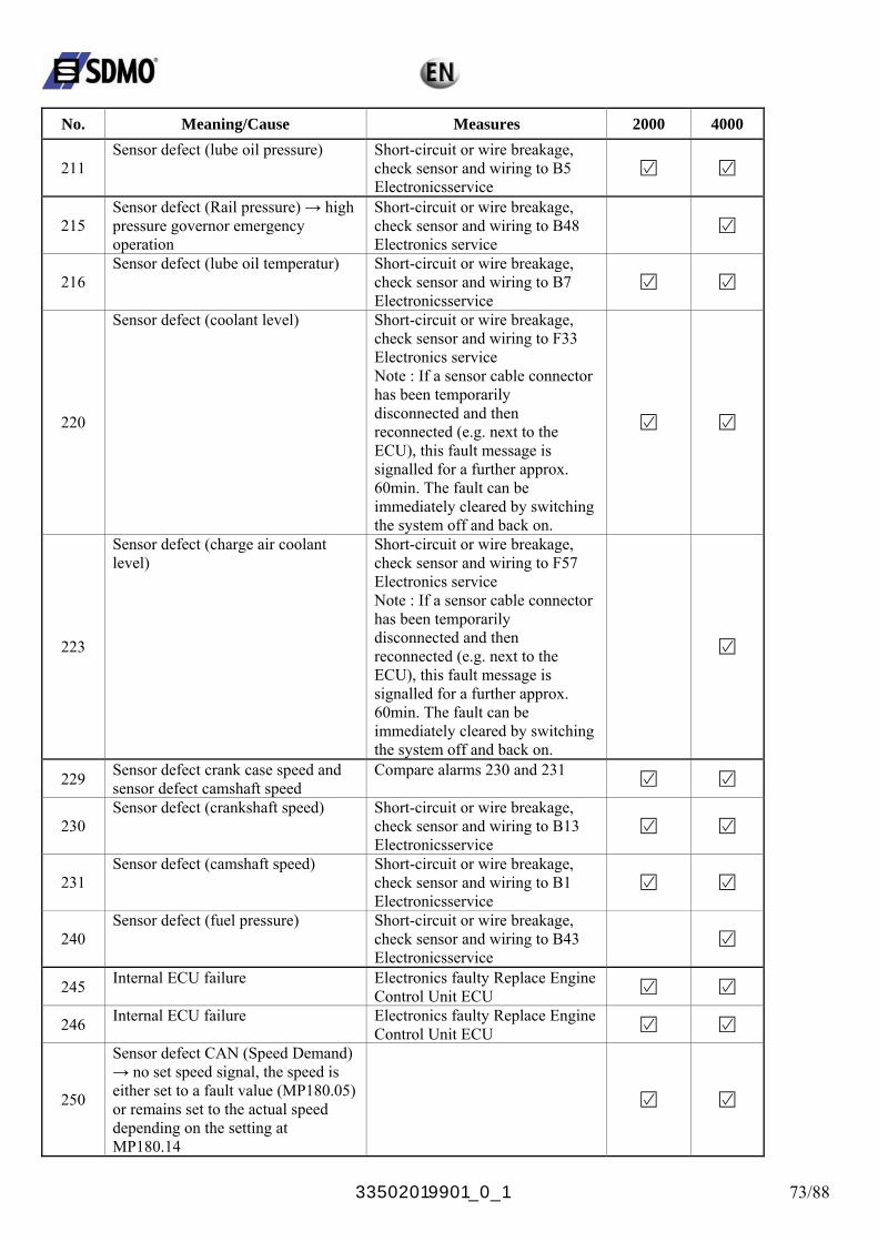
33502019901_0_1 73/88
No. Meaning/Cause Measures 2000 4000
211 Sensor defect (lube oil pressure) Short-circuit or wire breakage,
check sensor and wiring to B5 Electronicsservice
215 Sensor defect (Rail pressure) → high pressure governor emergency operation
Short-circuit or wire breakage, check sensor and wiring to B48 Electronics service
216 Sensor defect (lube oil temperatur) Short-circuit or wire breakage,
check sensor and wiring to B7 Electronicsservice
220
Sensor defect (coolant level) Short-circuit or wire breakage, check sensor and wiring to F33 Electronics service Note : If a sensor cable connector has been temporarily disconnected and then reconnected (e.g. next to the ECU), this fault message is signalled for a further approx. 60min. The fault can be immediately cleared by switching the system off and back on.
223
Sensor defect (charge air coolant level)
Short-circuit or wire breakage, check sensor and wiring to F57 Electronics service Note : If a sensor cable connector has been temporarily disconnected and then reconnected (e.g. next to the ECU), this fault message is signalled for a further approx. 60min. The fault can be immediately cleared by switching the system off and back on.
229 Sensor defect crank case speed and sensor defect camshaft speed
Compare alarms 230 and 231
230 Sensor defect (crankshaft speed) Short-circuit or wire breakage,
check sensor and wiring to B13 Electronicsservice
231 Sensor defect (camshaft speed) Short-circuit or wire breakage,
check sensor and wiring to B1 Electronicsservice
240 Sensor defect (fuel pressure) Short-circuit or wire breakage,
check sensor and wiring to B43 Electronicsservice
245 Internal ECU failure Electronics faulty Replace Engine Control Unit ECU
246 Internal ECU failure Electronics faulty Replace Engine Control Unit ECU
250
Sensor defect CAN (Speed Demand) → no set speed signal, the speed is either set to a fault value (MP180.05) or remains set to the actual speed depending on the setting at MP180.14
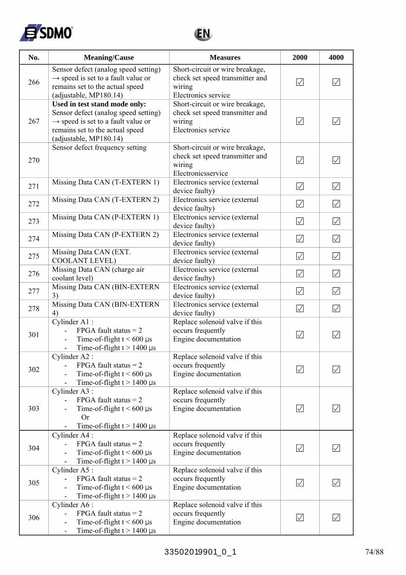
33502019901_0_1 74/88
No. Meaning/Cause Measures 2000 4000
266
Sensor defect (analog speed setting) → speed is set to a fault value or remains set to the actual speed (adjustable, MP180.14)
Short-circuit or wire breakage, check set speed transmitter and wiring Electronics service
267
Used in test stand mode only: Sensor defect (analog speed setting) → speed is set to a fault value or remains set to the actual speed (adjustable, MP180.14)
Short-circuit or wire breakage, check set speed transmitter and wiring Electronics service
270
Sensor defect frequency setting Short-circuit or wire breakage, check set speed transmitter and wiring Electronicsservice
271 Missing Data CAN (T-EXTERN 1) Electronics service (external device faulty)
272 Missing Data CAN (T-EXTERN 2) Electronics service (external device faulty)
273 Missing Data CAN (P-EXTERN 1) Electronics service (external device faulty)
274 Missing Data CAN (P-EXTERN 2) Electronics service (external device faulty)
275 Missing Data CAN (EXT. COOLANT LEVEL)
Electronics service (external device faulty)
276 Missing Data CAN (charge air coolant level)
Electronics service (external device faulty)
277 Missing Data CAN (BIN-EXTERN 3)
Electronics service (external device faulty)
278 Missing Data CAN (BIN-EXTERN 4)
Electronics service (external device faulty)
301
Cylinder A1 : - FPGA fault status = 2 - Time-of-flight t < 600 μs - Time-of-flight t > 1400 μs
Replace solenoid valve if this occurs frequently Engine documentation
302
Cylinder A2 : - FPGA fault status = 2 - Time-of-flight t < 600 μs - Time-of-flight t > 1400 μs
Replace solenoid valve if this occurs frequently Engine documentation
303
Cylinder A3 : - FPGA fault status = 2 - Time-of-flight t < 600 μs Or - Time-of-flight t > 1400 μs
Replace solenoid valve if this occurs frequently Engine documentation
304
Cylinder A4 : - FPGA fault status = 2 - Time-of-flight t < 600 μs - Time-of-flight t > 1400 μs
Replace solenoid valve if this occurs frequently Engine documentation
305
Cylinder A5 : - FPGA fault status = 2 - Time-of-flight t < 600 μs - Time-of-flight t > 1400 μs
Replace solenoid valve if this occurs frequently Engine documentation
306
Cylinder A6 : - FPGA fault status = 2 - Time-of-flight t < 600 μs - Time-of-flight t > 1400 μs
Replace solenoid valve if this occurs frequently Engine documentation
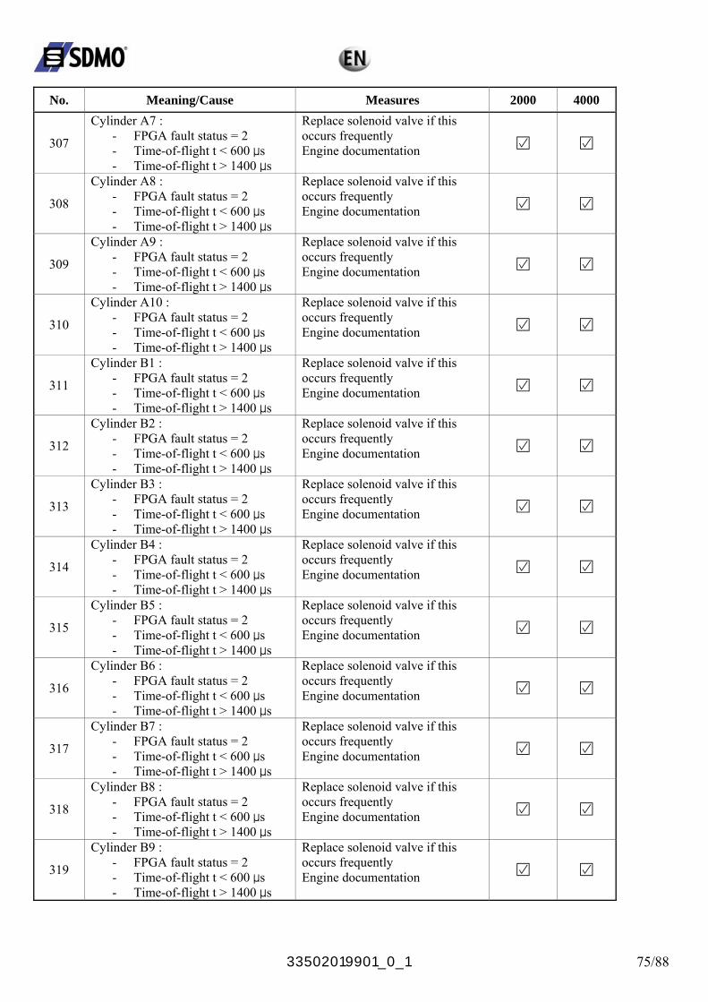
33502019901_0_1 75/88
No. Meaning/Cause Measures 2000 4000
307
Cylinder A7 : - FPGA fault status = 2 - Time-of-flight t < 600 μs - Time-of-flight t > 1400 μs
Replace solenoid valve if this occurs frequently Engine documentation
308
Cylinder A8 : - FPGA fault status = 2 - Time-of-flight t < 600 μs - Time-of-flight t > 1400 μs
Replace solenoid valve if this occurs frequently Engine documentation
309
Cylinder A9 : - FPGA fault status = 2 - Time-of-flight t < 600 μs - Time-of-flight t > 1400 μs
Replace solenoid valve if this occurs frequently Engine documentation
310
Cylinder A10 : - FPGA fault status = 2 - Time-of-flight t < 600 μs - Time-of-flight t > 1400 μs
Replace solenoid valve if this occurs frequently Engine documentation
311
Cylinder B1 : - FPGA fault status = 2 - Time-of-flight t < 600 μs - Time-of-flight t > 1400 μs
Replace solenoid valve if this occurs frequently Engine documentation
312
Cylinder B2 : - FPGA fault status = 2 - Time-of-flight t < 600 μs - Time-of-flight t > 1400 μs
Replace solenoid valve if this occurs frequently Engine documentation
313
Cylinder B3 : - FPGA fault status = 2 - Time-of-flight t < 600 μs - Time-of-flight t > 1400 μs
Replace solenoid valve if this occurs frequently Engine documentation
314
Cylinder B4 : - FPGA fault status = 2 - Time-of-flight t < 600 μs - Time-of-flight t > 1400 μs
Replace solenoid valve if this occurs frequently Engine documentation
315
Cylinder B5 : - FPGA fault status = 2 - Time-of-flight t < 600 μs - Time-of-flight t > 1400 μs
Replace solenoid valve if this occurs frequently Engine documentation
316
Cylinder B6 : - FPGA fault status = 2 - Time-of-flight t < 600 μs - Time-of-flight t > 1400 μs
Replace solenoid valve if this occurs frequently Engine documentation
317
Cylinder B7 : - FPGA fault status = 2 - Time-of-flight t < 600 μs - Time-of-flight t > 1400 μs
Replace solenoid valve if this occurs frequently Engine documentation
318
Cylinder B8 : - FPGA fault status = 2 - Time-of-flight t < 600 μs - Time-of-flight t > 1400 μs
Replace solenoid valve if this occurs frequently Engine documentation
319
Cylinder B9 : - FPGA fault status = 2 - Time-of-flight t < 600 μs - Time-of-flight t > 1400 μs
Replace solenoid valve if this occurs frequently Engine documentation
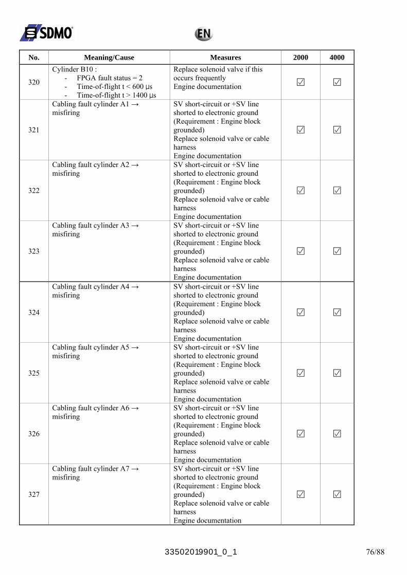
33502019901_0_1 76/88
No. Meaning/Cause Measures 2000 4000
320
Cylinder B10 : - FPGA fault status = 2 - Time-of-flight t < 600 μs - Time-of-flight t > 1400 μs
Replace solenoid valve if this occurs frequently Engine documentation
321
Cabling fault cylinder A1 → misfiring
SV short-circuit or +SV line shorted to electronic ground (Requirement : Engine block grounded) Replace solenoid valve or cable harness Engine documentation
322
Cabling fault cylinder A2 → misfiring
SV short-circuit or +SV line shorted to electronic ground (Requirement : Engine block grounded) Replace solenoid valve or cable harness Engine documentation
323
Cabling fault cylinder A3 → misfiring
SV short-circuit or +SV line shorted to electronic ground (Requirement : Engine block grounded) Replace solenoid valve or cable harness Engine documentation
324
Cabling fault cylinder A4 → misfiring
SV short-circuit or +SV line shorted to electronic ground (Requirement : Engine block grounded) Replace solenoid valve or cable harness Engine documentation
325
Cabling fault cylinder A5 → misfiring
SV short-circuit or +SV line shorted to electronic ground (Requirement : Engine block grounded) Replace solenoid valve or cable harness Engine documentation
326
Cabling fault cylinder A6 → misfiring
SV short-circuit or +SV line shorted to electronic ground (Requirement : Engine block grounded) Replace solenoid valve or cable harness Engine documentation
327
Cabling fault cylinder A7 → misfiring
SV short-circuit or +SV line shorted to electronic ground (Requirement : Engine block grounded) Replace solenoid valve or cable harness Engine documentation
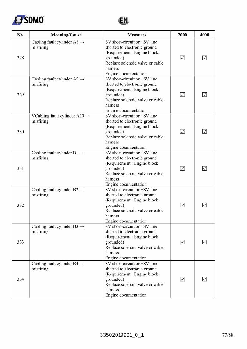
33502019901_0_1 77/88
No. Meaning/Cause Measures 2000 4000
328
Cabling fault cylinder A8 → misfiring
SV short-circuit or +SV line shorted to electronic ground (Requirement : Engine block grounded) Replace solenoid valve or cable harness Engine documentation
329
Cabling fault cylinder A9 → misfiring
SV short-circuit or +SV line shorted to electronic ground (Requirement : Engine block grounded) Replace solenoid valve or cable harness Engine documentation
330
VCabling fault cylinder A10 → misfiring
SV short-circuit or +SV line shorted to electronic ground (Requirement : Engine block grounded) Replace solenoid valve or cable harness Engine documentation
331
Cabling fault cylinder B1 → misfiring
SV short-circuit or +SV line shorted to electronic ground (Requirement : Engine block grounded) Replace solenoid valve or cable harness Engine documentation
332
Cabling fault cylinder B2 → misfiring
SV short-circuit or +SV line shorted to electronic ground (Requirement : Engine block grounded) Replace solenoid valve or cable harness Engine documentation
333
Cabling fault cylinder B3 → misfiring
SV short-circuit or +SV line shorted to electronic ground (Requirement : Engine block grounded) Replace solenoid valve or cable harness Engine documentation
334
Cabling fault cylinder B4 → misfiring
SV short-circuit or +SV line shorted to electronic ground (Requirement : Engine block grounded) Replace solenoid valve or cable harness Engine documentation
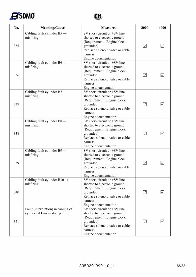
33502019901_0_1 78/88
No. Meaning/Cause Measures 2000 4000
335
Cabling fault cylinder B5 → misfiring
SV short-circuit or +SV line shorted to electronic ground (Requirement : Engine block grounded) Replace solenoid valve or cable harness Engine documentation
336
Cabling fault cylinder B6 → misfiring
SV short-circuit or +SV line shorted to electronic ground (Requirement : Engine block grounded) Replace solenoid valve or cable harness Engine documentation
337
Cabling fault cylinder B7 → misfiring
SV short-circuit or +SV line shorted to electronic ground (Requirement : Engine block grounded) Replace solenoid valve or cable harness Engine documentation
338
Cabling fault cylinder B8 → misfiring
SV short-circuit or +SV line shorted to electronic ground (Requirement : Engine block grounded) Replace solenoid valve or cable harness Engine documentation
339
Cabling fault cylinder B9 → misfiring
SV short-circuit or +SV line shorted to electronic ground (Requirement : Engine block grounded) Replace solenoid valve or cable harness Engine documentation
340
Cabling fault cylinder B10 → misfiring
SV short-circuit or +SV line shorted to electronic ground (Requirement : Engine block grounded) Replace solenoid valve or cable harness Engine documentation
341
Fault (interruption) in cabling of cylinder A1 → misfiring
SV short-circuit or +SV line shorted to electronic ground (Requirement : Engine block grounded) Replace solenoid valve or cable harness Engine documentation
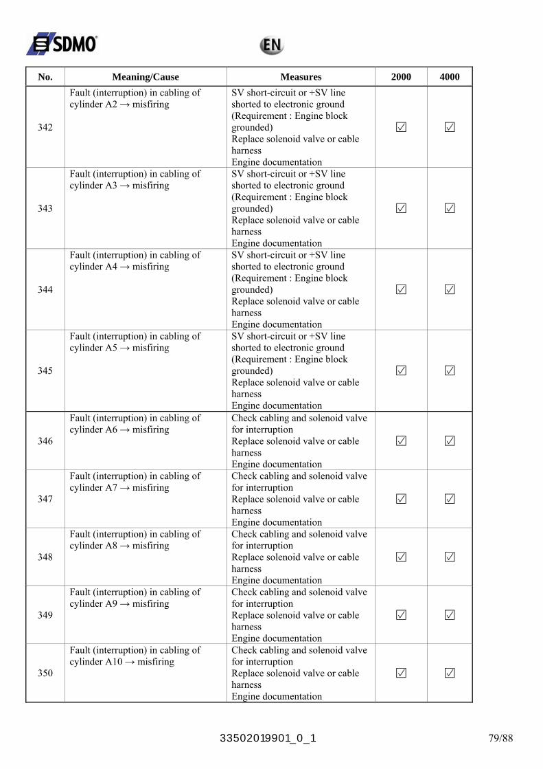
33502019901_0_1 79/88
No. Meaning/Cause Measures 2000 4000
342
Fault (interruption) in cabling of cylinder A2 → misfiring
SV short-circuit or +SV line shorted to electronic ground (Requirement : Engine block grounded) Replace solenoid valve or cable harness Engine documentation
343
Fault (interruption) in cabling of cylinder A3 → misfiring
SV short-circuit or +SV line shorted to electronic ground (Requirement : Engine block grounded) Replace solenoid valve or cable harness Engine documentation
344
Fault (interruption) in cabling of cylinder A4 → misfiring
SV short-circuit or +SV line shorted to electronic ground (Requirement : Engine block grounded) Replace solenoid valve or cable harness Engine documentation
345
Fault (interruption) in cabling of cylinder A5 → misfiring
SV short-circuit or +SV line shorted to electronic ground (Requirement : Engine block grounded) Replace solenoid valve or cable harness Engine documentation
346
Fault (interruption) in cabling of cylinder A6 → misfiring
Check cabling and solenoid valve for interruption Replace solenoid valve or cable harness Engine documentation
347
Fault (interruption) in cabling of cylinder A7 → misfiring
Check cabling and solenoid valve for interruption Replace solenoid valve or cable harness Engine documentation
348
Fault (interruption) in cabling of cylinder A8 → misfiring
Check cabling and solenoid valve for interruption Replace solenoid valve or cable harness Engine documentation
349
Fault (interruption) in cabling of cylinder A9 → misfiring
Check cabling and solenoid valve for interruption Replace solenoid valve or cable harness Engine documentation
350
Fault (interruption) in cabling of cylinder A10 → misfiring
Check cabling and solenoid valve for interruption Replace solenoid valve or cable harness Engine documentation
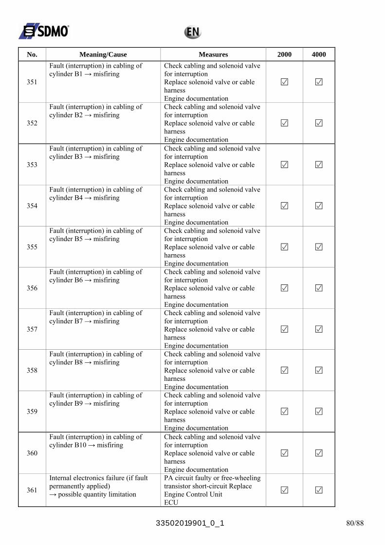
33502019901_0_1 80/88
No. Meaning/Cause Measures 2000 4000
351
Fault (interruption) in cabling of cylinder B1 → misfiring
Check cabling and solenoid valve for interruption Replace solenoid valve or cable harness Engine documentation
352
Fault (interruption) in cabling of cylinder B2 → misfiring
Check cabling and solenoid valve for interruption Replace solenoid valve or cable harness Engine documentation
353
Fault (interruption) in cabling of cylinder B3 → misfiring
Check cabling and solenoid valve for interruption Replace solenoid valve or cable harness Engine documentation
354
Fault (interruption) in cabling of cylinder B4 → misfiring
Check cabling and solenoid valve for interruption Replace solenoid valve or cable harness Engine documentation
355
Fault (interruption) in cabling of cylinder B5 → misfiring
Check cabling and solenoid valve for interruption Replace solenoid valve or cable harness Engine documentation
356
Fault (interruption) in cabling of cylinder B6 → misfiring
Check cabling and solenoid valve for interruption Replace solenoid valve or cable harness Engine documentation
357
Fault (interruption) in cabling of cylinder B7 → misfiring
Check cabling and solenoid valve for interruption Replace solenoid valve or cable harness Engine documentation
358
Fault (interruption) in cabling of cylinder B8 → misfiring
Check cabling and solenoid valve for interruption Replace solenoid valve or cable harness Engine documentation
359
Fault (interruption) in cabling of cylinder B9 → misfiring
Check cabling and solenoid valve for interruption Replace solenoid valve or cable harness Engine documentation
360
Fault (interruption) in cabling of cylinder B10 → misfiring
Check cabling and solenoid valve for interruption Replace solenoid valve or cable harness Engine documentation
361
Internal electronics failure (if fault permanently applied) → possible quantity limitation
PA circuit faulty or free-wheeling transistor short-circuit Replace Engine Control Unit ECU
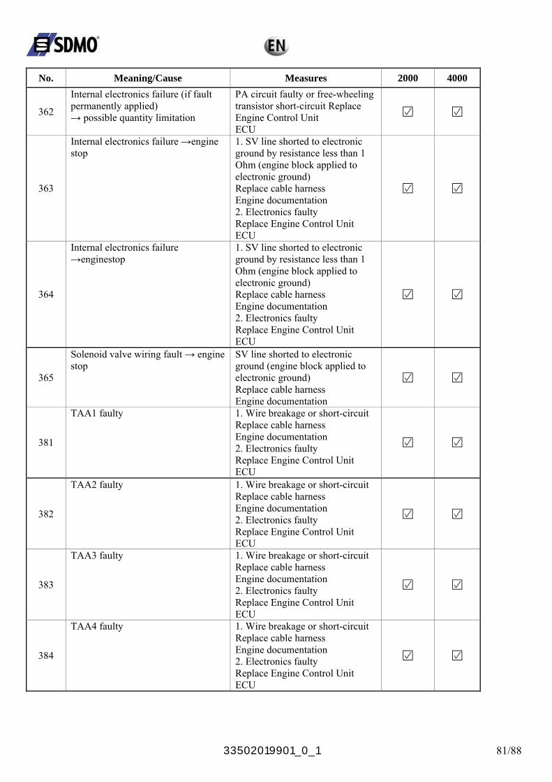
33502019901_0_1 81/88
No. Meaning/Cause Measures 2000 4000
362
Internal electronics failure (if fault permanently applied) → possible quantity limitation
PA circuit faulty or free-wheeling transistor short-circuit Replace Engine Control Unit ECU
363
Internal electronics failure →engine stop
1. SV line shorted to electronic ground by resistance less than 1 Ohm (engine block applied to electronic ground) Replace cable harness Engine documentation 2. Electronics faulty Replace Engine Control Unit ECU
364
Internal electronics failure →enginestop
1. SV line shorted to electronic ground by resistance less than 1 Ohm (engine block applied to electronic ground) Replace cable harness Engine documentation 2. Electronics faulty Replace Engine Control Unit ECU
365
Solenoid valve wiring fault → engine stop
SV line shorted to electronic ground (engine block applied to electronic ground) Replace cable harness Engine documentation
381
TAA1 faulty 1. Wire breakage or short-circuit Replace cable harness Engine documentation 2. Electronics faulty Replace Engine Control Unit ECU
382
TAA2 faulty 1. Wire breakage or short-circuit Replace cable harness Engine documentation 2. Electronics faulty Replace Engine Control Unit ECU
383
TAA3 faulty 1. Wire breakage or short-circuit Replace cable harness Engine documentation 2. Electronics faulty Replace Engine Control Unit ECU
384
TAA4 faulty 1. Wire breakage or short-circuit Replace cable harness Engine documentation 2. Electronics faulty Replace Engine Control Unit ECU
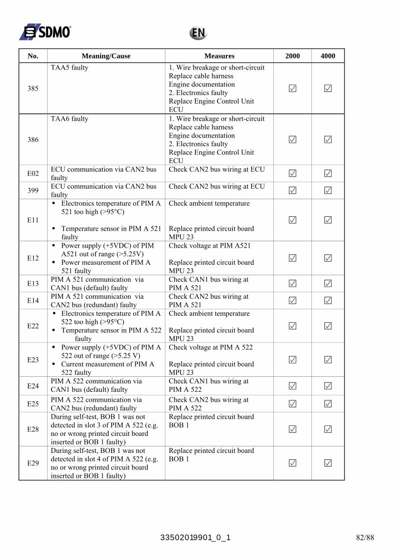
33502019901_0_1 82/88
No. Meaning/Cause Measures 2000 4000
385
TAA5 faulty 1. Wire breakage or short-circuit Replace cable harness Engine documentation 2. Electronics faulty Replace Engine Control Unit ECU
386
TAA6 faulty 1. Wire breakage or short-circuit Replace cable harness Engine documentation 2. Electronics faulty Replace Engine Control Unit ECU
E02 ECU communication via CAN2 bus faulty
Check CAN2 bus wiring at ECU
399 ECU communication via CAN2 bus faulty
Check CAN2 bus wiring at ECU
E11
Electronics temperature of PIM A 521 too high (>95°C)
Temperature sensor in PIM A 521
faulty
Check ambient temperature Replace printed circuit board MPU 23
E12
Power supply (+5VDC) of PIM A521 out of range (>5.25V)
Power measurement of PIM A 521 faulty
Check voltage at PIM A521 Replace printed circuit board MPU 23
E13 PIM A 521 communication via CAN1 bus (default) faulty
Check CAN1 bus wiring at PIM A 521
E14 PIM A 521 communication via CAN2 bus (redundant) faulty
Check CAN2 bus wiring at PIM A 521
E22
Electronics temperature of PIM A 522 too high (>95°C)
Temperature sensor in PIM A 522 faulty
Check ambient temperature Replace printed circuit board MPU 23
E23
Power supply (+5VDC) of PIM A 522 out of range (>5.25 V)
Current measurement of PIM A 522 faulty
Check voltage at PIM A 522 Replace printed circuit board MPU 23
E24 PIM A 522 communication via CAN1 bus (default) faulty
Check CAN1 bus wiring at PIM A 522
E25 PIM A 522 communication via CAN2 bus (redundant) faulty
Check CAN2 bus wiring at PIM A 522
E28
During self-test, BOB 1 was not detected in slot 3 of PIM A 522 (e.g. no or wrong printed circuit board inserted or BOB 1 faulty)
Replace printed circuit board BOB 1
E29
During self-test, BOB 1 was not detected in slot 4 of PIM A 522 (e.g. no or wrong printed circuit board inserted or BOB 1 faulty)
Replace printed circuit board BOB 1
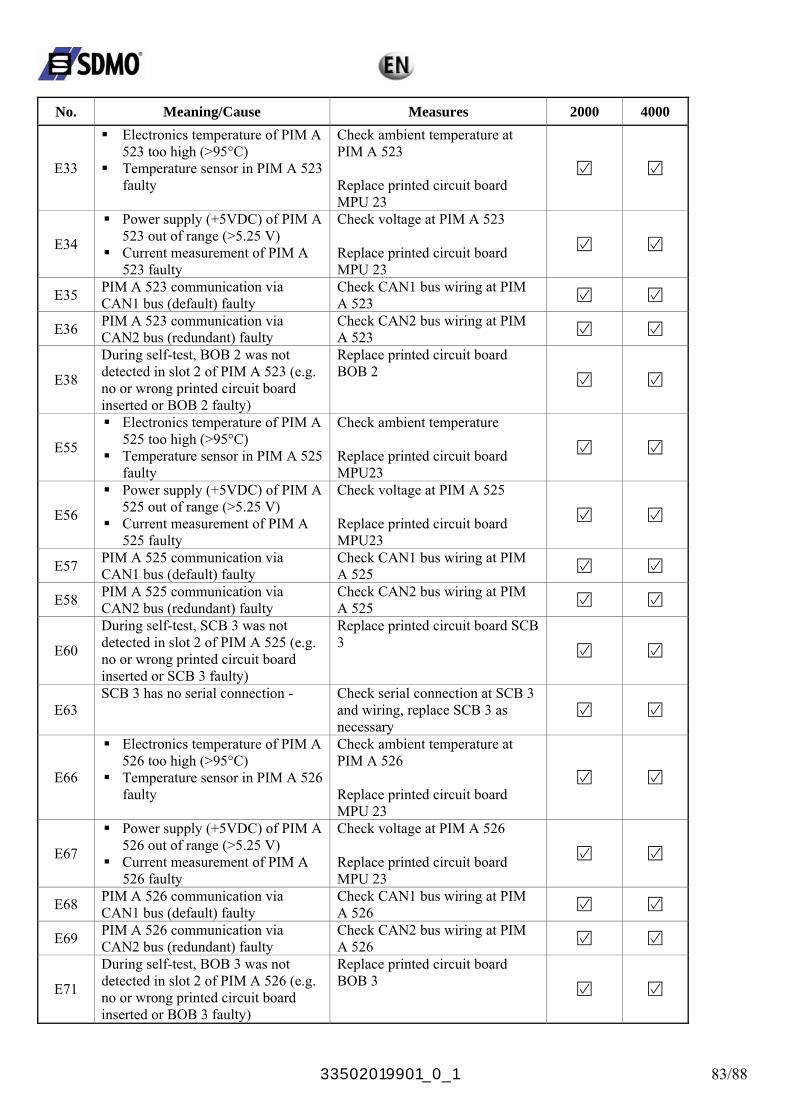
33502019901_0_1 83/88
No. Meaning/Cause Measures 2000 4000
E33
Electronics temperature of PIM A 523 too high (>95°C)
Temperature sensor in PIM A 523 faulty
Check ambient temperature at PIM A 523 Replace printed circuit board MPU 23
E34
Power supply (+5VDC) of PIM A 523 out of range (>5.25 V)
Current measurement of PIM A 523 faulty
Check voltage at PIM A 523 Replace printed circuit board MPU 23
E35 PIM A 523 communication via CAN1 bus (default) faulty
Check CAN1 bus wiring at PIM A 523
E36 PIM A 523 communication via CAN2 bus (redundant) faulty
Check CAN2 bus wiring at PIM A 523
E38
During self-test, BOB 2 was not detected in slot 2 of PIM A 523 (e.g. no or wrong printed circuit board inserted or BOB 2 faulty)
Replace printed circuit board BOB 2
E55
Electronics temperature of PIM A 525 too high (>95°C)
Temperature sensor in PIM A 525 faulty
Check ambient temperature Replace printed circuit board MPU23
E56
Power supply (+5VDC) of PIM A 525 out of range (>5.25 V)
Current measurement of PIM A 525 faulty
Check voltage at PIM A 525 Replace printed circuit board MPU23
E57 PIM A 525 communication via CAN1 bus (default) faulty
Check CAN1 bus wiring at PIM A 525
E58 PIM A 525 communication via CAN2 bus (redundant) faulty
Check CAN2 bus wiring at PIM A 525
E60
During self-test, SCB 3 was not detected in slot 2 of PIM A 525 (e.g. no or wrong printed circuit board inserted or SCB 3 faulty)
Replace printed circuit board SCB 3
E63 SCB 3 has no serial connection - Check serial connection at SCB 3
and wiring, replace SCB 3 as necessary
E66
Electronics temperature of PIM A 526 too high (>95°C)
Temperature sensor in PIM A 526 faulty
Check ambient temperature at PIM A 526 Replace printed circuit board MPU 23
E67
Power supply (+5VDC) of PIM A 526 out of range (>5.25 V)
Current measurement of PIM A 526 faulty
Check voltage at PIM A 526 Replace printed circuit board MPU 23
E68 PIM A 526 communication via CAN1 bus (default) faulty
Check CAN1 bus wiring at PIM A 526
E69 PIM A 526 communication via CAN2 bus (redundant) faulty
Check CAN2 bus wiring at PIM A 526
E71
During self-test, BOB 3 was not detected in slot 2 of PIM A 526 (e.g. no or wrong printed circuit board inserted or BOB 3 faulty)
Replace printed circuit board BOB 3
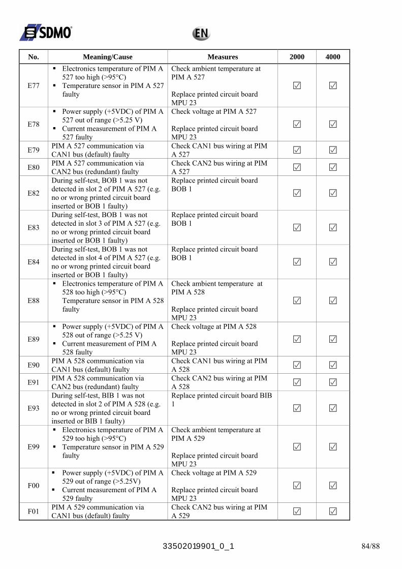
33502019901_0_1 84/88
No. Meaning/Cause Measures 2000 4000
E77
Electronics temperature of PIM A 527 too high (>95°C)
Temperature sensor in PIM A 527 faulty
Check ambient temperature at PIM A 527 Replace printed circuit board MPU 23
E78
Power supply (+5VDC) of PIM A 527 out of range (>5.25 V)
Current measurement of PIM A 527 faulty
Check voltage at PIM A 527 Replace printed circuit board MPU 23
E79 PIM A 527 communication via CAN1 bus (default) faulty
Check CAN1 bus wiring at PIM A 527
E80 PIM A 527 communication via CAN2 bus (redundant) faulty
Check CAN2 bus wiring at PIM A 527
E82
During self-test, BOB 1 was not detected in slot 2 of PIM A 527 (e.g. no or wrong printed circuit board inserted or BOB 1 faulty)
Replace printed circuit board BOB 1
E83
During self-test, BOB 1 was not detected in slot 3 of PIM A 527 (e.g. no or wrong printed circuit board inserted or BOB 1 faulty)
Replace printed circuit board BOB 1
E84
During self-test, BOB 1 was not detected in slot 4 of PIM A 527 (e.g. no or wrong printed circuit board inserted or BOB 1 faulty)
Replace printed circuit board BOB 1
E88
Electronics temperature of PIM A 528 too high (>95°C) Temperature sensor in PIM A 528 faulty
Check ambient temperature at PIM A 528 Replace printed circuit board MPU 23
E89
Power supply (+5VDC) of PIM A 528 out of range (>5.25 V)
Current measurement of PIM A 528 faulty
Check voltage at PIM A 528 Replace printed circuit board MPU 23
E90 PIM A 528 communication via CAN1 bus (default) faulty
Check CAN1 bus wiring at PIM A 528
E91 PIM A 528 communication via CAN2 bus (redundant) faulty
Check CAN2 bus wiring at PIM A 528
E93
During self-test, BIB 1 was not detected in slot 2 of PIM A 528 (e.g. no or wrong printed circuit board inserted or BIB 1 faulty)
Replace printed circuit board BIB 1
E99
Electronics temperature of PIM A 529 too high (>95°C)
Temperature sensor in PIM A 529 faulty
Check ambient temperature at PIM A 529 Replace printed circuit board MPU 23
F00
Power supply (+5VDC) of PIM A 529 out of range (>5.25V)
Current measurement of PIM A 529 faulty
Check voltage at PIM A 529 Replace printed circuit board MPU 23
F01 PIM A 529 communication via CAN1 bus (default) faulty
Check CAN2 bus wiring at PIM A 529
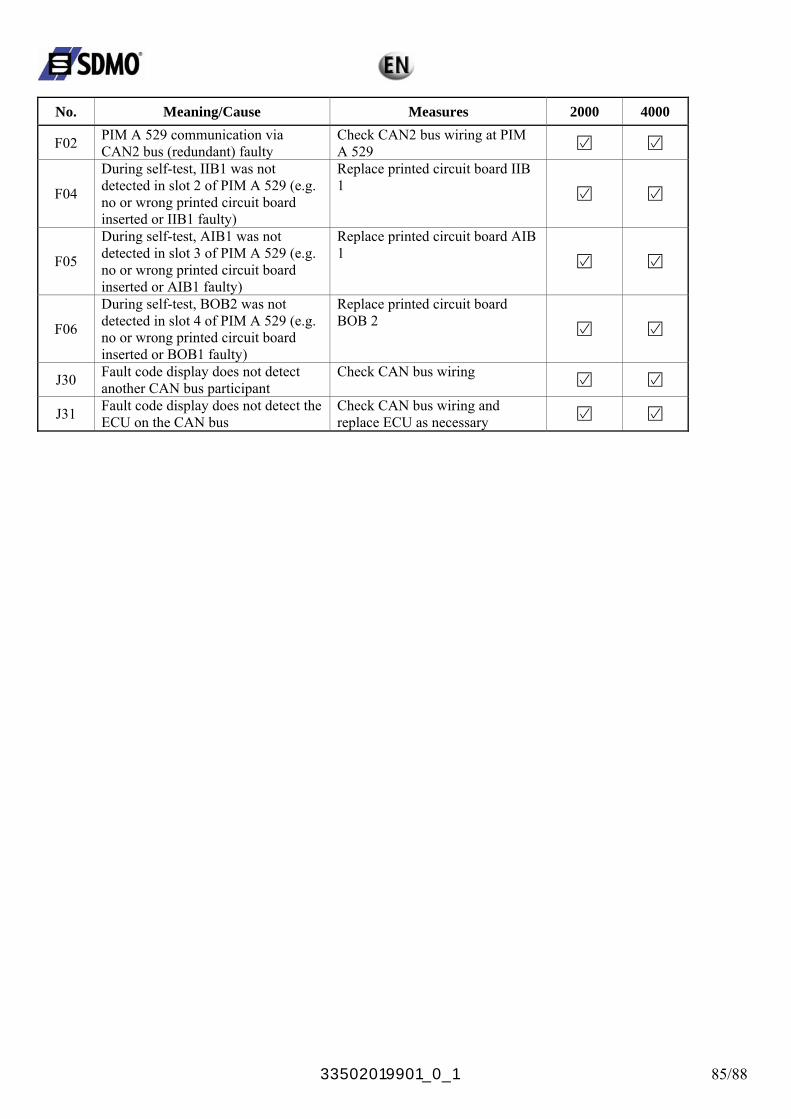
33502019901_0_1 85/88
No. Meaning/Cause Measures 2000 4000
F02 PIM A 529 communication via CAN2 bus (redundant) faulty
Check CAN2 bus wiring at PIM A 529
F04
During self-test, IIB1 was not detected in slot 2 of PIM A 529 (e.g. no or wrong printed circuit board inserted or IIB1 faulty)
Replace printed circuit board IIB 1
F05
During self-test, AIB1 was not detected in slot 3 of PIM A 529 (e.g. no or wrong printed circuit board inserted or AIB1 faulty)
Replace printed circuit board AIB 1
F06
During self-test, BOB2 was not detected in slot 4 of PIM A 529 (e.g. no or wrong printed circuit board inserted or BOB1 faulty)
Replace printed circuit board BOB 2
J30 Fault code display does not detect another CAN bus participant
Check CAN bus wiring
J31 Fault code display does not detect the ECU on the CAN bus
Check CAN bus wiring and replace ECU as necessary
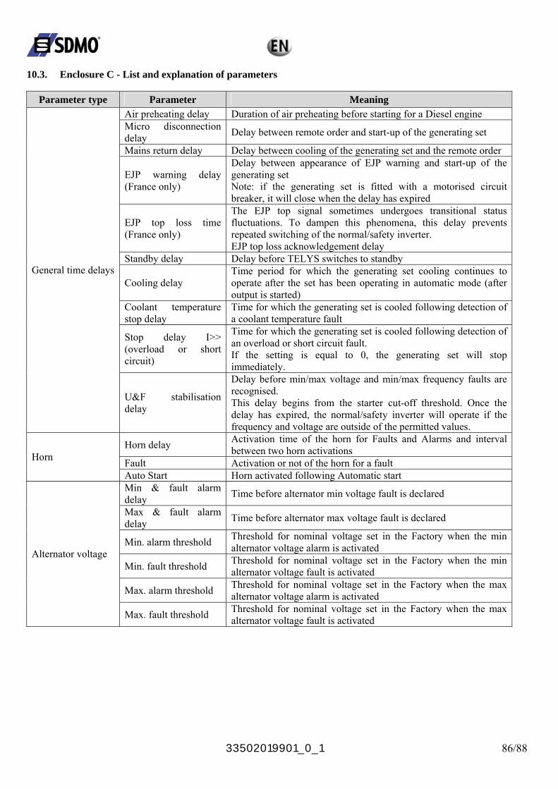
33502019901_0_1 86/88
10.3. Enclosure C - List and explanation of parameters
Parameter type Parameter Meaning Air preheating delay Duration of air preheating before starting for a Diesel engine Micro disconnection delay Delay between remote order and start-up of the generating set
Mains return delay Delay between cooling of the generating set and the remote order
EJP warning delay (France only)
Delay between appearance of EJP warning and start-up of the generating set Note: if the generating set is fitted with a motorised circuit breaker, it will close when the delay has expired
EJP top loss time (France only)
The EJP top signal sometimes undergoes transitional status fluctuations. To dampen this phenomena, this delay prevents repeated switching of the normal/safety inverter. EJP top loss acknowledgement delay
Standby delay Delay before TELYS switches to standby
Cooling delay Time period for which the generating set cooling continues to operate after the set has been operating in automatic mode (after output is started)
Coolant temperature stop delay
Time for which the generating set is cooled following detection of a coolant temperature fault
Stop delay I>> (overload or short circuit)
Time for which the generating set is cooled following detection of an overload or short circuit fault. If the setting is equal to 0, the generating set will stop immediately.
General time delays
U&F stabilisation delay
Delay before min/max voltage and min/max frequency faults are recognised. This delay begins from the starter cut-off threshold. Once the delay has expired, the normal/safety inverter will operate if the frequency and voltage are outside of the permitted values.
Horn delay Activation time of the horn for Faults and Alarms and interval between two horn activations
Fault Activation or not of the horn for a fault Horn
Auto Start Horn activated following Automatic start Min & fault alarm delay Time before alternator min voltage fault is declared
Max & fault alarm delay Time before alternator max voltage fault is declared
Min. alarm threshold Threshold for nominal voltage set in the Factory when the min alternator voltage alarm is activated
Min. fault threshold Threshold for nominal voltage set in the Factory when the min alternator voltage fault is activated
Max. alarm threshold Threshold for nominal voltage set in the Factory when the max alternator voltage alarm is activated
Alternator voltage
Max. fault threshold Threshold for nominal voltage set in the Factory when the max alternator voltage fault is activated
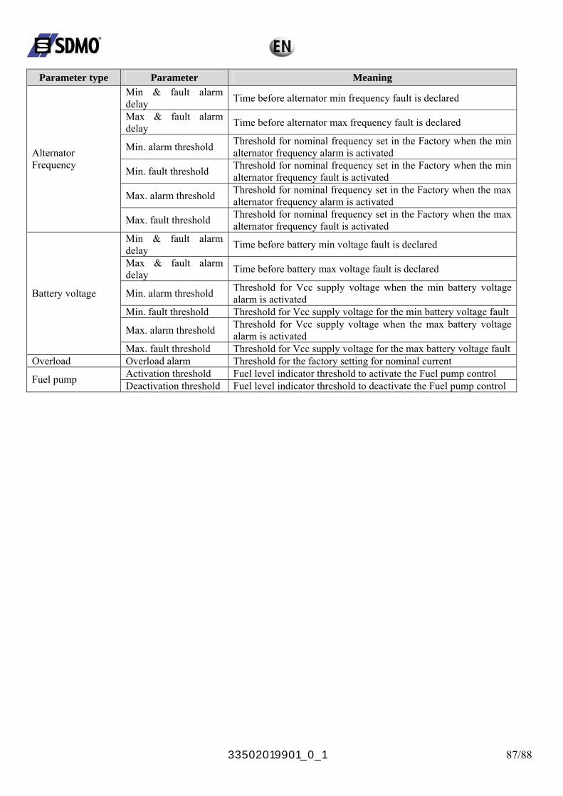
33502019901_0_1 87/88
Parameter type Parameter Meaning
Min & fault alarm delay Time before alternator min frequency fault is declared
Max & fault alarm delay Time before alternator max frequency fault is declared
Min. alarm threshold Threshold for nominal frequency set in the Factory when the min alternator frequency alarm is activated
Min. fault threshold Threshold for nominal frequency set in the Factory when the min alternator frequency fault is activated
Max. alarm threshold Threshold for nominal frequency set in the Factory when the max alternator frequency alarm is activated
Alternator Frequency
Max. fault threshold Threshold for nominal frequency set in the Factory when the max alternator frequency fault is activated
Min & fault alarm delay Time before battery min voltage fault is declared
Max & fault alarm delay Time before battery max voltage fault is declared
Min. alarm threshold Threshold for Vcc supply voltage when the min battery voltage alarm is activated
Min. fault threshold Threshold for Vcc supply voltage for the min battery voltage fault
Max. alarm threshold Threshold for Vcc supply voltage when the max battery voltage alarm is activated
Battery voltage
Max. fault threshold Threshold for Vcc supply voltage for the max battery voltage fault Overload Overload alarm Threshold for the factory setting for nominal current
Activation threshold Fuel level indicator threshold to activate the Fuel pump control Fuel pump Deactivation threshold Fuel level indicator threshold to deactivate the Fuel pump control
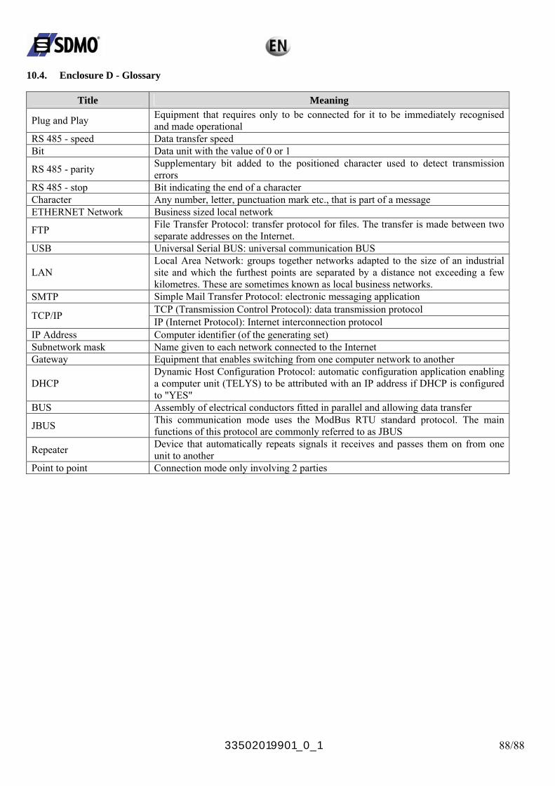
33502019901_0_1 88/88
10.4. Enclosure D - Glossary
Title Meaning
Plug and Play Equipment that requires only to be connected for it to be immediately recognised and made operational
RS 485 - speed Data transfer speed Bit Data unit with the value of 0 or 1
RS 485 - parity Supplementary bit added to the positioned character used to detect transmission errors
RS 485 - stop Bit indicating the end of a character Character Any number, letter, punctuation mark etc., that is part of a message ETHERNET Network Business sized local network
FTP File Transfer Protocol: transfer protocol for files. The transfer is made between two separate addresses on the Internet.
USB Universal Serial BUS: universal communication BUS
LAN Local Area Network: groups together networks adapted to the size of an industrial site and which the furthest points are separated by a distance not exceeding a few kilometres. These are sometimes known as local business networks.
SMTP Simple Mail Transfer Protocol: electronic messaging application TCP (Transmission Control Protocol): data transmission protocol TCP/IP IP (Internet Protocol): Internet interconnection protocol
IP Address Computer identifier (of the generating set) Subnetwork mask Name given to each network connected to the Internet Gateway Equipment that enables switching from one computer network to another
DHCP Dynamic Host Configuration Protocol: automatic configuration application enabling a computer unit (TELYS) to be attributed with an IP address if DHCP is configured to "YES"
BUS Assembly of electrical conductors fitted in parallel and allowing data transfer
JBUS This communication mode uses the ModBus RTU standard protocol. The main functions of this protocol are commonly referred to as JBUS
Repeater Device that automatically repeats signals it receives and passes them on from one unit to another
Point to point Connection mode only involving 2 parties