· · 2017-05-08sgx 5150 iot device gateway user guide 2 intellectual property © 2017...
TRANSCRIPT

Part Number 900-776-R
SGX 5150IoT Device Gateway
User Guide
Revision C March 2017

Intellectual Property
© 2017 Lantronix, Inc. All rights reserved. No part of the contents of this publication may be transmitted or reproduced in any form or by any means without the written permission of Lantronix.
Lantronix is a registered trademark of Lantronix, Inc. in the United States and other countries. DeviceInstaller is a trademark of Lantronix, Inc.
Patented: http://patents.lantronix.com; additional patents pending.
Wi-Fi is a registered trademark of the Wi-Fi Alliance Corporation. Windows and Internet Explorer are registered trademarks of Microsoft Corporation. Mozilla and Firefox are registered trademarks of the Mozilla Foundation. Chrome is a trademark of Google Inc. Safari is a registered trademark of Apple Inc. All other trademarks and trade names are the property of their respective holders.
Warranty
For details on the Lantronix warranty policy, please go to our web site at www.lantronix.com/support/warranty.
Contacts
Lantronix, Inc.7535 Irvine Center DriveSuite 100Irvine, CA 92618, USAToll Free: 800-526-8766Phone: 949-453-3990Fax: 949-453-3995
Technical Support Online: www.lantronix.com/support
Sales Offices
For a current list of our domestic and international sales offices, go to the Lantronix web site at www.lantronix.com/about/contact.
Disclaimer
All information contained herein is provided “AS IS.” Lantronix undertakes no obligation to update the information in this publication. Lantronix does not make, and specifically disclaims, all warranties of any kind (express, implied or otherwise) regarding title, non-infringement, fitness, quality, accuracy, completeness, usefulness, suitability or performance of the information provided herein. Lantronix shall have no liability whatsoever to any user for any damages, losses and causes of action (whether in contract or in tort or otherwise) in connection with the user’s access or usage of any of the information or content contained herein. The information and specifications contained in this document are subject to change without notice.
SGX 5150 IoT Device Gateway User Guide 2

Open Source Software
Some applications are Open Source software licensed under the Berkeley Software Distribution (BSD) license, the GNU General Public License (GPL) as published by the Free Software Foundation (FSF), and the Python Software Foundation (PSF) License Agreement for Python 2.7.6 (Python License). Lantronix grants you no right to receive source code to the Open Source software. Your use of each Open Source component or software is subject to the terms of the applicable license. The BSD license is available at http://opensource.org/licenses. The GNU General Public License is available at http://www.gnu.org/licenses/. The Python License is available at https://www.python.org/download/releases/2.7/license/.Your use of each Open Source component or software is subject to the terms of the applicable license.
wpa_supplicant: http://w1.fi/cgit/hostap/plain/wpa_supplicant/README
Openssl : http://openssl.org/source/license.html
Busybox: http://busybox.net/license.html
Dropbear: https://secure.ucc.asn.au/hg/dropbear/raw-file/tip/LICENSE
VSFTPD: https://security.appspot.com/vsftpd.html#about
Bootstrap: https://github.com/twbs/bootstrap/blob/master/LICENSE
Python: https://www.python.org/download/releases/2.7/license/
Linux kernel version 3.10.0.
OPEN SOURCE SOFTWARE IS DISTRIBUTED WITHOUT ANY WARRANTY, INCLUDING ANY IMPLIED WARRANTY OF MERCHANTABILITY OR FITNESS FOR A PARTICULAR PURPOSE. SEE THE APPLICABLE LICENSE AGREEMENT FOR ADDITIONAL INFORMATION.
Revision History
Date Rev. Comments
October 2016 A Initial document for firmware release 8.0.0.0.
November 2016 B Updated user guide to include software features available in all SGX 5150 device gateway models. The user will experience differing featuer availability depending on the model type installed.
March 2017 C Updated user guide GRE section.
SGX 5150 IoT Device Gateway User Guide 3

Table of Contents
Intellectual Property ________________________________________________________2
Warranty _________________________________________________________________2
Contacts _________________________________________________________________2
Disclaimer ________________________________________________________________2
Open Source Software ______________________________________________________3
Revision History ___________________________________________________________3
List of Figures ____________________________________________________________10
List of Tables _____________________________________________________________11
1: Using This Guide 14Purpose and Audience _____________________________________________________14
Summary of Chapters ______________________________________________________14
Additional Documentation ___________________________________________________14
2: Introduction 16Key Features _____________________________________________________________16
Applications ______________________________________________________________17
SGX 5150 User Cases _____________________________________________________18
Protocol Support __________________________________________________________19
Troubleshooting Capabilities _________________________________________________19
Configuration Methods _____________________________________________________19
Addresses and Port Numbers ________________________________________________20
Hardware Address _____________________________________________________20
IP Address ___________________________________________________________20
Port Numbers _________________________________________________________20
Product Information Label ___________________________________________________20
3: Installation of the SGX 5150 22Package Contents _________________________________________________________22
User-Supplied Items _______________________________________________________22
Hardware Components _____________________________________________________23
Front Panel ___________________________________________________________23
Back Panel ___________________________________________________________23
USB Connection _______________________________________________________24
Power _______________________________________________________________25
Ethernet Ports _________________________________________________________25
Wi-Fi Protected Setup (WPS) _____________________________________________26
Reset Button __________________________________________________________27
To Start WPS _________________________________________________________27
SGX 5150 IoT Device Gateway User Guide 4

Installing the SGX 5150 ____________________________________________________27
Optional SGX 5150 Bracket _________________________________________________29
Wireless Quick Connect ____________________________________________________30
4: Using DeviceInstaller 31Installing DeviceInstaller ____________________________________________________31
Accessing the SGX 5150 Using DeviceInstaller __________________________________31
Next Step ____________________________________________________________33
5: Configuration Using Web Manager 34Accessing Web Manager ___________________________________________________34
Status Page ______________________________________________________________35
Web Manager Components _________________________________________________37
Navigating Web Manager ___________________________________________________38
6: Network Settings 40Access Point _____________________________________________________________40
To View or Configure Access Point Settings _________________________________40
Bridge __________________________________________________________________41
Bridge Status and Configuration ___________________________________________42
To View or Configure Bridge Settings ______________________________________43
Wired (eth0) Network ______________________________________________________43
Interface Status and Configuration _________________________________________43
To Configure Network Interface Settings ____________________________________45
Link Status and Configuration ____________________________________________45
To Configure Network Link Settings ________________________________________46
QoS Statistics and Configuration __________________________________________46
To View and Configure Wired Network QoS Settings __________________________47
Wired (eth0) Network Failover ____________________________________________47
To View and Configure Wired Network Failover Settings ________________________48
Wireless (wlan0) Network ___________________________________________________48
Wireless (wlan0) Network Interface ________________________________________48
To View or Configure Wireless Network Interface Settings ______________________50
Wireless (wlan0) Network Link ____________________________________________50
To View or Configure Network Link Settings _________________________________51
Wireless (wlan0) Network QoS ____________________________________________51
To View or Configure Wireless Network QoS Settings __________________________52
Wireless (wlan0) Network Failover _________________________________________52
To View or Configure Wireless Network Failover Settings _______________________53
Wired (usb0) Network ______________________________________________________53
Interface (usb0) Status and Configuration ___________________________________53
To Configure Network Interface Settings ____________________________________55
SGX 5150 IoT Device Gateway User Guide 5

QoS Statistics and Configuration __________________________________________55
To View and Configure Wired Network (USB) QoS Settings _____________________56
Wired (usb0) Network Failover ____________________________________________56
To View and Configure Wired (USB0) Network Failover Settings _________________57
Protocol Stack ____________________________________________________________57
IP Settings ___________________________________________________________57
To Configure IP Protocol Stack Settings ____________________________________58
ICMP Settings _________________________________________________________58
To Configure ICMP Protocol Stack Settings __________________________________58
ARP Settings _________________________________________________________58
To Configure ARP Network Stack Settings __________________________________59
VPN ____________________________________________________________________59
Configuring VPN Settings ________________________________________________61
Wi-Fi Protected Setup ______________________________________________________61
To Initiate WPS ________________________________________________________61
To Show WPS Status ___________________________________________________62
WLAN Scan/QuickConnect __________________________________________________62
To View WLAN Link Scan and Status Information _____________________________63
WLAN Profiles ____________________________________________________________63
Configuring WLAN Profile Settings _________________________________________63
7: Filesystem 67File Transfer and Modification ________________________________________________67
To View, Transfer, or Modify Filesystem Files ________________________________68
8: Diagnostics 69DNS ____________________________________________________________________69
Accessing the DNS Settings ______________________________________________69
Hardware ________________________________________________________________70
To View Hardware Information ____________________________________________70
IP Sockets _______________________________________________________________70
To View the List of IP Sockets ____________________________________________70
Log ____________________________________________________________________71
To Configure the Diagnostic Log Output ____________________________________71
Memory _________________________________________________________________71
To View Memory Usage _________________________________________________71
Ping ____________________________________________________________________71
To Ping a Remote Host _________________________________________________72
Processes _______________________________________________________________72
To View Process Information _____________________________________________72
Routes __________________________________________________________________72
Threads _________________________________________________________________73
To View Thread Information ______________________________________________73
SGX 5150 IoT Device Gateway User Guide 6
Traceroute _______________________________________________________________73
To Perform a Traceroute ________________________________________________73
9: Administration 74Actions _________________________________________________________________75
To Configure Action Settings _____________________________________________76
Python ______________________________________________________________76
Applications ______________________________________________________________77
To Configure Application Settings _________________________________________78
CLI _____________________________________________________________________78
CLI Status and Configuration _____________________________________________78
To View and Configure Basic CLI Settings ___________________________________79
Clock ___________________________________________________________________79
To Specify a Clock-Setting Method ________________________________________79
Discovery _______________________________________________________________80
To Configure Discovery _________________________________________________80
Email ___________________________________________________________________80
To View, Configure and Send Email ________________________________________81
FTP ____________________________________________________________________81
To Configure FTP Settings _______________________________________________82
Gateway ________________________________________________________________82
Status _______________________________________________________________82
WAN ________________________________________________________________82
WAN MAC Address Filters _______________________________________________83
To Configure Gateway WAN Settings ______________________________________83
Port Forwarding _______________________________________________________83
To Configure Gateway Port Forwarding Settings ______________________________84
Static Routes _________________________________________________________84
To Configure Gateway Static Route Settings _________________________________85
DHCP Server _________________________________________________________85
To Configure Gateway DHCP Server Settings ________________________________86
Static Lease Listing ____________________________________________________86
Routing Protocols ______________________________________________________86
To Configure Gateway Routing Protocol Settings _____________________________87
Virtual IP _____________________________________________________________87
To Configure Gateway Virtual IP __________________________________________88
GRE ___________________________________________________________________88
To Configure GRE Settings ______________________________________________88
Host ____________________________________________________________________89
To Configure Host Settings ______________________________________________89
HTTP ___________________________________________________________________90
Interface Status, Configuration and Authentication ____________________________90
To View or Configure HTTP ______________________________________________91
SGX 5150 IoT Device Gateway User Guide 7
To Configure HTTP Authentication _________________________________________92
Line ____________________________________________________________________92
Line Status and Configuration ____________________________________________92
To View and Configure Line Configuration and Command Mode _________________94
USB ____________________________________________________________________94
USB Statistics _________________________________________________________94
To View USB Statistics __________________________________________________94
USB Configuration _____________________________________________________95
To Configure USB Settings ______________________________________________95
USB Command Mode ___________________________________________________95
To Configure USB Command Mode ________________________________________96
Modbus _________________________________________________________________96
Serial Transmission Mode _______________________________________________96
Modbus Statistics ______________________________________________________97
Modbus Configuration __________________________________________________97
To View and Configure the Modbus Server __________________________________97
SMTP __________________________________________________________________98
To Configure SMTP Settings _____________________________________________98
SNMP Settings ___________________________________________________________98
To Configure SNMP Settings _____________________________________________99
SSH ____________________________________________________________________99
SSH Server: Host Keys _________________________________________________99
SSH Server: Authorized Users ___________________________________________100
SSH Client: Known Hosts _______________________________________________101
SSH Client: Users _____________________________________________________101
To Configure SSH Settings _____________________________________________103
SSL ___________________________________________________________________103
Credentials __________________________________________________________103
To Create a New Credential _____________________________________________103
To Delete a Credential _________________________________________________104
To Configure an SSL Credential to Use an Uploaded Certificate _________________105
To Configure an SSL Credential to Use a Self-Signed Certificate ________________105
Trusted Authorities ____________________________________________________106
To Upload an Authority Certificate ________________________________________106
CSR (Certificate Signing Request) ________________________________________107
Syslog _________________________________________________________________108
To Configure Syslog Settings ____________________________________________108
System ________________________________________________________________109
To access System settings: _____________________________________________110
Terminal _______________________________________________________________111
To Configure the Terminal Network Connection ______________________________111
To Configure the Terminal Line or USB Connection __________________________112
SGX 5150 IoT Device Gateway User Guide 8

Tunnel _________________________________________________________________112
Tunnel Statistics ______________________________________________________112
To View Tunnel Statistics _______________________________________________112
Serial Settings _______________________________________________________112
To Configure Tunnel Serial Settings _______________________________________113
Packing Mode ________________________________________________________113
To Configure Tunnel Packing Mode Settings ________________________________114
Accept Mode _________________________________________________________114
To Configure Tunnel Accept Mode Settings _________________________________116
Connect Mode _______________________________________________________116
To Configure Tunnel Connect Mode Settings _______________________________119
Connecting Multiple Hosts ______________________________________________119
Host List Promotion ___________________________________________________119
Disconnect Mode _____________________________________________________120
To Configure Tunnel Disconnect Mode Settings _____________________________120
Modem Emulation _____________________________________________________121
To Configure Tunnel Modem Emulation Settings _____________________________121
User Management ________________________________________________________122
To Change the User Admin Password _____________________________________122
XML ___________________________________________________________________122
To Export Configuration ________________________________________________123
To Export Status ______________________________________________________123
To Import Configuration ________________________________________________124
Quick Setup _____________________________________________________________125
To Utilize Quick Setup _________________________________________________126
A: Lantronix Technical Support 128
B: Compliance 129RoHS, REACH and WEEE Compliance Statement ______________________________130
SGX 5150 IoT Device Gateway User Guide 9

SGX 5150 IoT Device Gateway User Guide 10
List of Figures
Figure 2-1 Serial/USB/Ethernet to Wi-Fi Connectivity_____________________________________18
Figure 2-2 Ethernet to Wi-Fi Bridge __________________________________________________18
Figure 2-3 Product Label __________________________________________________________21
Figure 3-1 Front Panel ____________________________________________________________23
Figure 3-3 Back Panel_____________________________________________________________23
Figure 3-12 Wi-Fi Protected Setup ___________________________________________________26
Figure 3-14 SGX 5150 Dimensions in Inches (in) and Millimeters (mm) ______________________28
Figure 3-15 Optional Bracket Installation ______________________________________________29
Figure 5-1 Status Page (Section 1 of 2) _______________________________________________35
Figure 5-2 Status Page (Section 2 of 2) _______________________________________________36
Figure 5-3 Components of the Web Manager Page ______________________________________37
Figure 5-4 Expandable Menu Bar Selections ___________________________________________37

List of Tables
Table 3-2 SGX 5150 LEDs and Descriptions __________________________________________ 23
Table 3-4 Serial RJ45 Connector Pinout and LEDs _____________________________________ 24
Table 3-5 USB Type C Connector Pinout _____________________________________________ 24
Table 3-6 Power Input Interface ____________________________________________________ 25
Table 3-7 Ethernet RJ45 Connector Pinout ___________________________________________ 25
Table 3-8 Left Ethernet LED _______________________________________________________ 25
Table 3-9 Right Ethernet LED______________________________________________________ 26
Table 3-10 WLAN Signal Strength Indicator at 2.4 GHz__________________________________ 26
Table 3-11 WLAN Signal Strength Indicator at 5 GHz ___________________________________ 26
Table 3-13 WPS Status Indicator ___________________________________________________ 27
Table 4-1 SGX 5150 Configuration in DeviceInstaller ___________________________________ 32
Table 5-5 Web Manager Pages ____________________________________________________ 38
Table 6-1 Access Point Settings ____________________________________________________ 40
Table 6-2 Bridge Settings _________________________________________________________ 42
Table 6-3 Wired (eth0) Network Interface_____________________________________________ 43
Table 6-4 Link (eth0) Configuration__________________________________________________ 45
Table 6-5 Wired (eth0) Network QoS Settings _________________________________________ 46
Table 6-6 Wired (eth0) Network Failover Settings ______________________________________ 47
Table 6-7 Wireless (wlan0) Interface Configuration _____________________________________ 48
Table 6-8 Wireless (wlan0) Link Configuration _________________________________________ 50
Table 6-9 Wireless (wlan0) Network QoS Settings______________________________________ 51
Table 6-10 Adding or Deleting Wireless (wlan0) Network QoS Settings _____________________ 52
Table 6-11 Wireless (wlan0) Network Failover _________________________________________ 52
Table 6-12 Wired (usb0) Network Interface ___________________________________________ 53
Table 6-13 Wired (usb0) Network QoS Settings________________________________________ 56
Table 6-14 Wired (usb0) Network Failover Settings _____________________________________ 56
Table 6-15 IP Protocol Stack Settings _______________________________________________ 57
Table 6-16 ICMP Protocol Stack Settings_____________________________________________ 58
Table 6-17 ARP Protocol Stack Settings _____________________________________________ 58
Table 6-18 VPN_________________________________________________________________ 59
Table 6-19 Wi-Fi Protected Setup___________________________________________________ 61
Table 6-20 WLAN Scan/Quick Connect Results________________________________________ 62
Table 6-21 WLAN Profiles_________________________________________________________ 63
Table 6-22 Individual WLAN Profile Settings __________________________________________ 64
Table 7-1 File Modification Settings _________________________________________________ 67
SGX 5150 IoT Device Gateway User Guide 11
Table 7-2 File Transfer Settings ____________________________________________________ 67
Table 8-1 DNS Settings __________________________________________________________ 69
Table 8-2 Log Settings ___________________________________________________________ 71
Table 8-3 Ping Configuration ______________________________________________________ 71
Table 8-4 Traceroute Settings______________________________________________________ 73
Table 9-1 Action Settings _________________________________________________________ 75
Table 9-2 Script Settings__________________________________________________________ 77
Table 9-3 CLI Configuration Settings ________________________________________________ 78
Table 9-4 Clock Settings__________________________________________________________ 79
Table 9-5 Discovery Settings ______________________________________________________ 80
Table 9-6 Email Configuration______________________________________________________ 80
Table 9-7 FTP Settings ___________________________________________________________ 81
Table 9-8 WAN Configuration ______________________________________________________ 82
Table 9-9 Adding a New MAC Address Filters _________________________________________ 83
Table 9-10 Port Forwarding Rules List _______________________________________________ 83
Table 9-11 Adding a New Port Forwarding Rule________________________________________ 84
Table 9-12 Static Route Setting Routes ______________________________________________ 84
Table 9-13 Adding a New Static Route_______________________________________________ 85
Table 9-14 DHCP Settings ________________________________________________________ 85
Table 9-15 Static Lease Listing_____________________________________________________ 86
Table 9-16 Add a Static Lease _____________________________________________________ 86
Table 9-17 Routing Protocol Settings ________________________________________________ 87
Table 9-18 Virtual IP Settings ______________________________________________________ 87
Table 9-19 GRE Settings _________________________________________________________ 88
Table 9-20 Host Settings__________________________________________________________ 89
Table 9-21 HTTP Configuration ____________________________________________________ 90
Table 9-22 HTTP Authentication____________________________________________________ 91
Table 9-23 Line Configuration Settings_______________________________________________ 92
Table 9-24 Line Command Mode Setting _____________________________________________ 93
Table 9-25 USB Configuration _____________________________________________________ 95
Table 9-26 USB Command Mode___________________________________________________ 95
Table 9-27 Byte Header of Modbus Application Protocol _________________________________ 96
Table 9-28 Modbus Transmission Modes_____________________________________________ 97
Table 9-29 Modbus Configuration___________________________________________________ 97
Table 9-30 SMTP Settings ________________________________________________________ 98
Table 9-31 SNMP Settings ________________________________________________________ 98
Table 9-32 SSH Server Host Keys _________________________________________________ 100
Table 9-33 SSH Server Authorized Users ___________________________________________ 100
SGX 5150 IoT Device Gateway User Guide 12

Table 9-34 SSH Client Known Hosts _______________________________________________ 101
Table 9-35 SSH Client Users _____________________________________________________ 102
Table 9-36 Create New Keys _____________________________________________________ 102
Table 9-37 SSL Credential - Upload Certificate _______________________________________ 104
Table 9-38 SSL Credential - Create New Self-Signed Certificate__________________________ 104
Table 9-39 SSL Trusted Authority__________________________________________________ 106
Table 9-40 SSL CSR (Certificate Signing Request) ____________________________________ 107
Table 9-41 System Settings ______________________________________________________ 109
Table 9-42 Terminal on Network and Line Settings ____________________________________ 111
Table 9-43 Tunnel Serial Settings__________________________________________________ 113
Table 9-44 Tunnel Packing Mode Settings ___________________________________________ 113
Table 9-45 Tunnel Accept Mode Settings____________________________________________ 115
Table 9-46 Tunnel Connect Mode Settings___________________________________________ 117
Table 9-47 Host Settings_________________________________________________________ 118
Table 9-48 Tunnel Disconnect Mode Settings ________________________________________ 120
Table 9-49 Tunnel Modem Emulation Settings________________________________________ 121
Table 9-50 Configuration from Filesystem ___________________________________________ 125
Table 9-51 Line(s) from single line Settings on the Filesystem____________________________ 125
Table 9-52 Bridge 1 (br0) Configuration _____________________________________________ 126
Table 9-53 Wi-Fi Protected Setup__________________________________________________ 126
Table 9-54 Current Configuration __________________________________________________ 126
Table 9-55 Available Networks ____________________________________________________ 127
Table B-1 Country Transmitter IDs _________________________________________________130
SGX 5150 IoT Device Gateway User Guide 13
1: Using This Guide
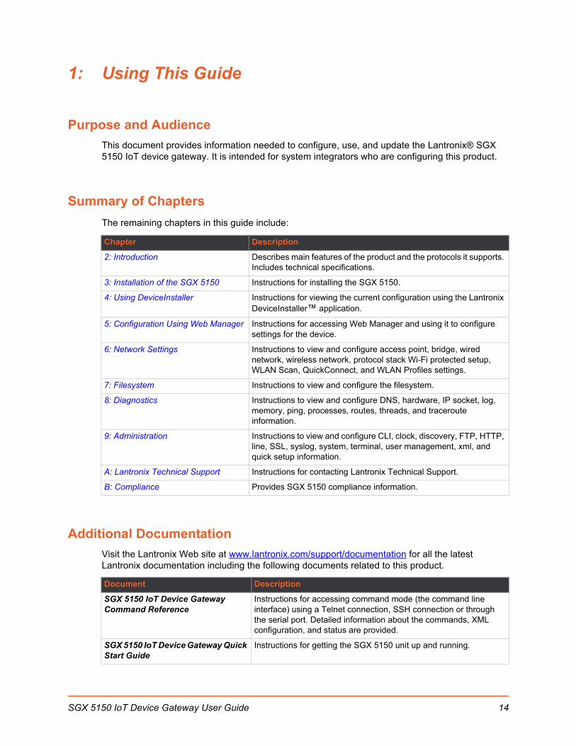
Purpose and Audience
This document provides information needed to configure, use, and update the Lantronix® SGX 5150 IoT device gateway. It is intended for system integrators who are configuring this product.
Summary of Chapters
The remaining chapters in this guide include:
Additional Documentation
Visit the Lantronix Web site at www.lantronix.com/support/documentation for all the latest Lantronix documentation including the following documents related to this product.
Chapter Description
2: Introduction Describes main features of the product and the protocols it supports. Includes technical specifications.
3: Installation of the SGX 5150 Instructions for installing the SGX 5150.
4: Using DeviceInstaller Instructions for viewing the current configuration using the Lantronix DeviceInstaller™ application.
5: Configuration Using Web Manager Instructions for accessing Web Manager and using it to configure settings for the device.
6: Network Settings Instructions to view and configure access point, bridge, wired network, wireless network, protocol stack Wi-Fi protected setup, WLAN Scan, QuickConnect, and WLAN Profiles settings.
7: Filesystem Instructions to view and configure the filesystem.
8: Diagnostics Instructions to view and configure DNS, hardware, IP socket, log, memory, ping, processes, routes, threads, and traceroute information.
9: Administration Instructions to view and configure CLI, clock, discovery, FTP, HTTP, line, SSL, syslog, system, terminal, user management, xml, and quick setup information.
A: Lantronix Technical Support Instructions for contacting Lantronix Technical Support.
B: Compliance Provides SGX 5150 compliance information.
Document Description
SGX 5150 IoT Device Gateway Command Reference
Instructions for accessing command mode (the command line interface) using a Telnet connection, SSH connection or through the serial port. Detailed information about the commands, XML configuration, and status are provided.
SGX 5150 IoT Device Gateway Quick Start Guide
Instructions for getting the SGX 5150 unit up and running.
SGX 5150 IoT Device Gateway User Guide 14

1: Using This Guide
DeviceInstaller Utility Online Help Instructions for using the Windows® operating system-based utility to locate the device and to view its current settings.
Com Port Redirectory Quick Start and Online Help
Instructions for using the Windows operating system-based utility to create virtual com ports.
Secure Com Port Redirector User Guide
Instructions for using the Windows operating system-based utility to create secure virtual com ports.
Document (continued) Description
SGX 5150 IoT Device Gateway User Guide 15

2: Introduction
The SGX 5150 is a turnkey WLAN IoT device gateway that securely connects deployed devices to the enterprise network through serial, USB or Ethernet interfaces. It simplifies enterprise Wi-Fi® deployments and accelerates the availability of connected devices within enterprise, medical/healthcare and industrial automation applications.
Note: This user guide describes all software features supported in the Lantronix SGX 5150 device gateway models available for purchase. Depending on the specific SGX 5150 device gateway model you have purchased, some descriptions may not apply.
Key Features
Power Supply: Flexible power options and input voltage range (one barrel connector for 9-30 VDC power source, USB type C VBUS 5V, and optional PoE power input via Ethernet RJ45 interface.
Controller: 32-bit ARM9 microprocessor running at 400 megahertz (Mhz) with 32 Kilobyte (KB) configurable cache.
Memory: 400 MHz ARM9, 64 MB SDRAM and 128 MB NAND flash
Ethernet:
- One RJ45 10Base-T/100Base-TX Ethernet port.
- Auto sensing
- Automatic MDI/MDI-X crossover
- Full duplex IEEE 802.3x flow control
- Half-duplex back pressure flow control
- Hardware Optional PoE Power Input (Class 2). Supports inputs at both Spare Pins or Ethernet Center Taps
Wireless:
- 5G Wi-Fi (IEEE 802.11ac)
• 1x1 ac (MCS0 - MCS9)
• 20, 40 and 80 MHz Channels with optional SGI
- IEEE 802.11 n
• 1x1 n (MCS0 - MCS7)
• 20 MHz and 40 MHz channel width with optional SGI
- Advanced 802.11 n/ac Features
• Tx/Rx Low Density Party Check (LDPC)
• Rx Space Time Block Coding (STBC)
- Compatible with IEEE 802.11 a/b/g and supports IEEE 802.11 d/h
- Bluetooth/WLAN Coexistence
- Dual band 2.4 GHz and 5 GHz
SGX 5150 IoT Device Gateway User Guide 16

2: Introduction
• 2.412 GHz - 2.484 GHz - Channels 1 - 14
• U-NII-1 (5.15 – 5.25 GHz) Channels 36, 40, 44, 48
• U-NII-2 (5.25 – 5.35 GHz) Channels 52, 56, 60, 64
• U-NII-2e (5.47 – 5.725 GHz) Channels 100 – 140
• U-NII-3 (5.725 – 5.825 GHz) Channels 149 - 165
Serial Ports: Two 300 to 921 kbaud with options of RS-232 serial ports or multi-protocol RS232/422/485 serial ports.
USB Ports: One USB 2.0 high speed interfaces via USB type C connector.
Configuration via CLI, XML and HTTP.
Ethernet to wireless tunneling.
Built-in site survey tool.
Temperature Range: Operates over a temperature range of -40°C to +70°C (-40°F to 158°F). The storage temperature range is -40°C to 85°C (-40°F to 185°F).
Applications
Home energy management systems
Medical device and clinical information system (CIS) integration
Asset and warehouse management
Mobile driven human-machine interface (HMI) and instrumentation
Industrial machines - weighing scales, automation controllers
SGX 5150 IoT Device Gateway User Guide 17
2: Introduction
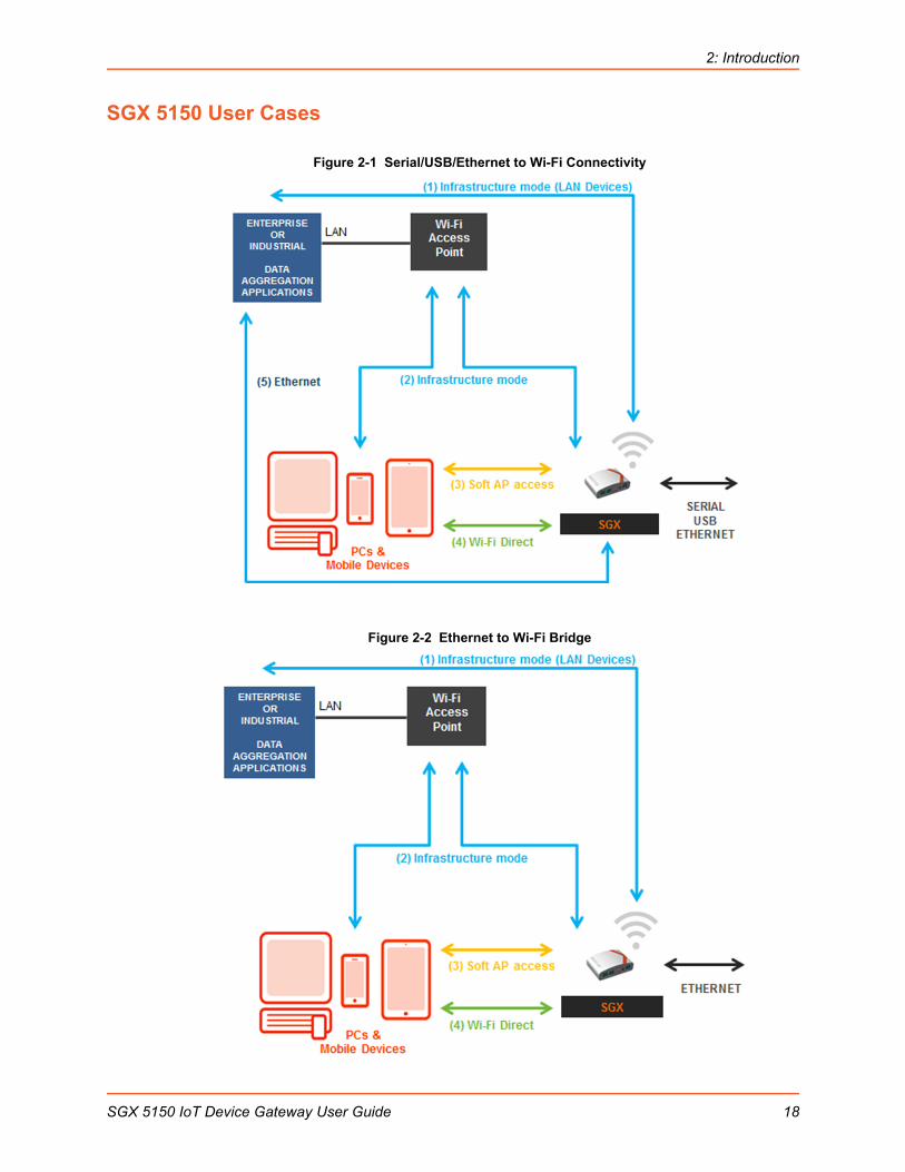
SGX 5150 User Cases
Figure 2-1 Serial/USB/Ethernet to Wi-Fi Connectivity
Figure 2-2 Ethernet to Wi-Fi Bridge
SGX 5150 IoT Device Gateway User Guide 18
2: Introduction
Protocol Support
The SGX 5150 contains a full-featured IP networking and wireless software stack:
DHCP Client, DHCP Server, DHCPv6 Client
uPnP (Discovery), LCAP (77FE), Telnet, SSH, SSLv3/TLSv1, (S)FTP, HTTP(S)
IPv4/IPv6, TCP, UDP, ICMP, ARP, Auto-IP, DNS, SNMP v2/v3
WPA/WPA2 Personal, WPA2 Enterprise (EAP-TLS, EAP-TTLS, EAP-PEAPv0/v1, EAP-FAST)
Troubleshooting Capabilities
The SGX 5150 offers a comprehensive diagnostic tool set that lets you troubleshoot problems quickly and easily. Diagnostic tools available in the CLI or Web Manager allow you to:
View critical hardware, memory, buffer pool, IP socket information and routing table
Perform ping and traceroute operations
Conduct forward or reverse DNS lookup operations
View all processes currently running on the SGX 5150 including CPU utilization
View system log messages
Configuration Methods
After installation, the SGX 5150 requires configuration. For the unit to operate correctly on a network, it must have a unique IP address on the network. There are four basic methods for logging into the SGX 5150 and assigning IP addresses and other configurable settings:
Web Manager: View and configure all settings easily through a web browser using the Lantronix Web Manager. See Chapter 5: Configuration Using Web Manager.
DeviceInstaller: Configure the IP address and related settings and view current settings on the SGX 5150 using a Graphical User Interface (GUI) on a PC attached to a network. You will need the latest version of the Lantronix® DeviceInstaller™ utility. See Chapter 4: Using DeviceInstaller.
Command Mode: Two methods for accessing Command Mode (CLI) include making a Telnet or SSH connection, or connecting a PC or other host running a terminal emulation program to the unit’s serial port. See the SGX 5150 IoT Device Gateway Command Reference for instructions and available commands.
XML: The SGX 5150 supports XML-based configuration and setup records that make device configuration transparent to users and administrators. XML is easily editable with a standard text or XML editor. See the SGX 5150 IoT Device Gateway Command Reference for instructions and commands.
SGX 5150 IoT Device Gateway User Guide 19

2: Introduction
Addresses and Port Numbers
Hardware AddressThe hardware address is also referred to as the Ethernet address, physical address, or MAC address. The first three bytes of the Ethernet address are fixed and identify the unit as a Lantronix product. The fourth, fifth, and sixth bytes are unique numbers assigned to each unit.
Sample ways hardware address may be represented:
00-80-A3-14-1B-18
00:80:A3:14:1B:18
IP AddressEvery device connected to an IP network must have a unique IPv4 address. This address references the specific unit.
Port NumbersEvery TCP connection and every UDP datagram is defined by a destination and source IP address, and a destination and source port number. For example, a Telnet server commonly uses TCP port number 23.
The following is a list of the default server port numbers running on the SGX 5150:
TCP Port 22: SSH Server (Command Mode configuration)
TCP Port 23: Telnet Server (Command Mode configuration)
TCP Port 80: HTTP (Web Manager Configuration)
TCP Port 21: FTP
TCP Port 443: HTTPS
UDP Port 30718: Lantronix Discovery Protocol
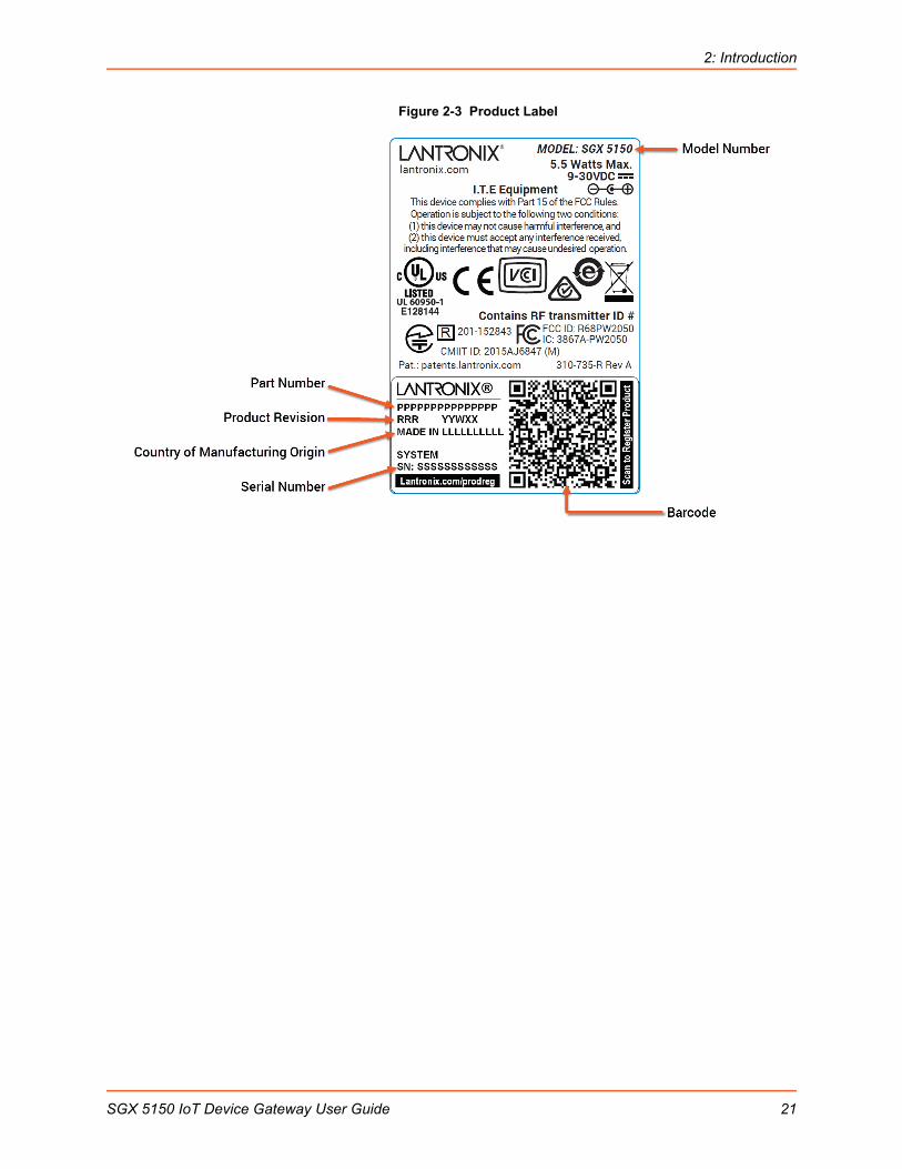
Product Information Label
The product information label on the device contains the following information about the specific unit:
Model Name
Product Part Number
Barcode
Product Revision
Country of Manufacturing Origin
Serial Number
SGX 5150 IoT Device Gateway User Guide 20
2: Introduction
Figure 2-3 Product Label
SGX 5150 IoT Device Gateway User Guide 21
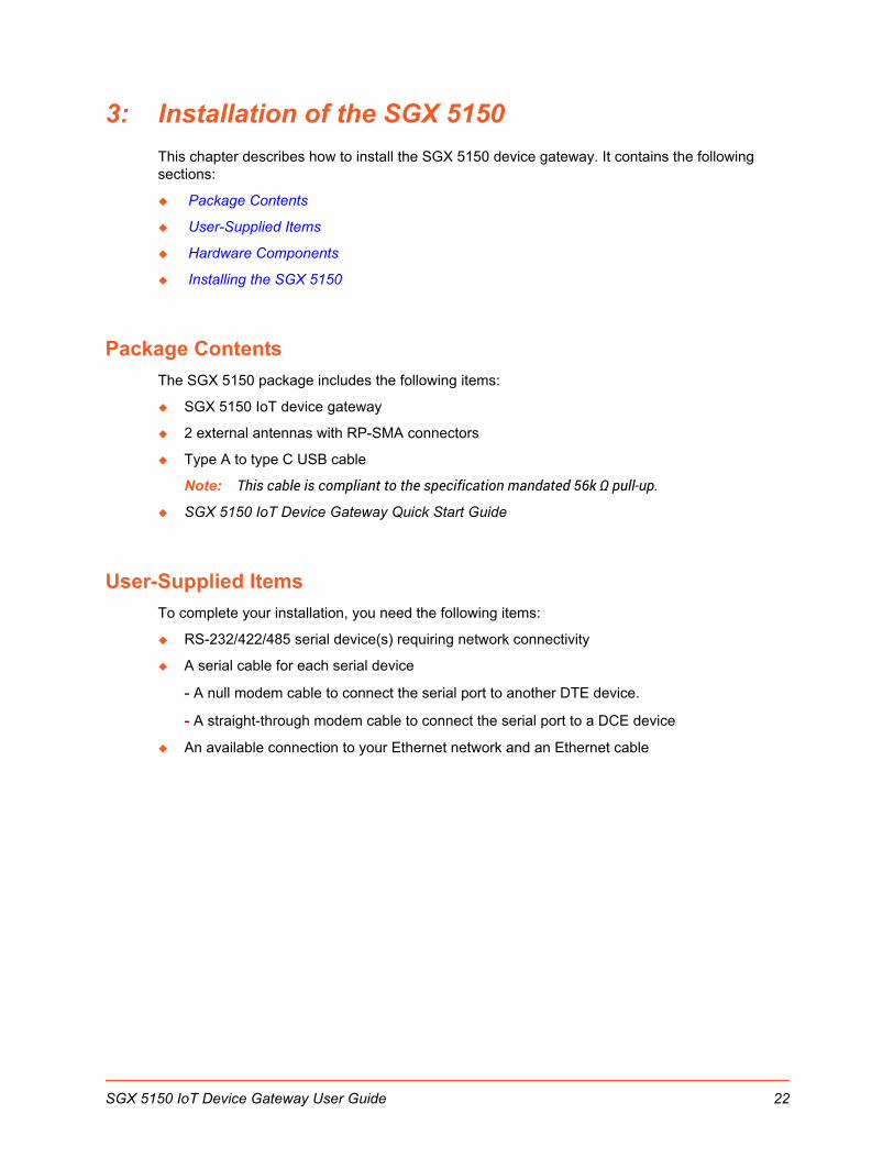
3: Installation of the SGX 5150
This chapter describes how to install the SGX 5150 device gateway. It contains the following sections:
Package Contents
User-Supplied Items
Hardware Components
Installing the SGX 5150
Package Contents
The SGX 5150 package includes the following items:
SGX 5150 IoT device gateway
2 external antennas with RP-SMA connectors
Type A to type C USB cable
Note: This cable is compliant to the specification mandated 56k Ω pull-up.
SGX 5150 IoT Device Gateway Quick Start Guide
User-Supplied Items
To complete your installation, you need the following items:
RS-232/422/485 serial device(s) requiring network connectivity
A serial cable for each serial device
- A null modem cable to connect the serial port to another DTE device.
- A straight-through modem cable to connect the serial port to a DCE device
An available connection to your Ethernet network and an Ethernet cable
SGX 5150 IoT Device Gateway User Guide 22

3: Installation of the SGX 5150
Hardware Components
Front Panel
Figure 3-1 Front Panel
Table 3-2 SGX 5150 LEDs and Descriptions
Note: In Table 3-2 above, the L indicates a longer LED blink while the S indicates shorter LED blink.
Back Panel
Figure 3-3 Back Panel
Serial Interface
One or two serial ports are available for the SGX 5150. Data rates can be configured for speeds between 300 and 921 kbaud. Hardware protocol options include the following:
Two RJ45 RS232 Serial Ports, or
Two RJ45 Multi-protocol RS232/422/485 ports, or
One RJ45 RS232 Serial Port
Note: Multi-protocol ports come with configurable terminations 120 ohm on TX+/- and RX+/-.
LED Description
Status No IP obtained from eth0 network: L, L, S, S, S No IP obtained from wlan0 network: L, L, L, S, S, S No IP obtained from the usb0 network: L, L, L, L, L, S No eth0 link: L, L, S, S No wlan link: L, L, L, S, S No usb0 link: L, L, L, L, L, S, S
WLAN The wlan indicator light and color pattern indicates the wlan status according to Table 3-10 and Table 3-11 and also reflects the WPS status according to Table 3-13.
Signal See Table 3-10 and Table 3-11 for signal strength indication information.
SGX 5150 IoT Device Gateway User Guide 23

3: Installation of the SGX 5150
Table 3-4 Serial RJ45 Connector Pinout and LEDs
USB ConnectionOne USB 2.0 HS/FS port with USB type C connector is available on the SGX 5150 and can be configured in two ways:
As a USB device (default setting) where the SGX 5150 can be powered by a VBUS 5V.
As a USB configurable host where the SGX 5150 can provide VBUS 5V 0.5A if powered by a Lantronix provided wall adapter or PoE (hardware optional).
Table 3-5 USB Type C Connector Pinout
Pin Number Signal Name for RS-232 Signal Name for RS-422/485 (4 wire)
1 RTS (output from SGX) TX+ (output from SGX)
2 DTR (output from SGX) Not used/do not connect.
3 TXD (output from SGX) TX- (output from SGX)
4 GND GND
5 GND GND
6 RXD (input to SGX) RX+ (input to SGX)
7 DCD (input to SGX) Not used/do not connect.
8 CTS (input to SGX) RX- (input to SGX)
Right LED Yellow for Transmit Data activities (TXD) Yellow for Transmit Data activities (TXD)
Left LED Green for Receive Data activities (RXD) Green for Receive Data activities (RXD)
Upper Row Pin Number
Lower Row Pin Number
Signal Name
A1 B1 Ground
A2 B2 No Connection
A3 B3 No Connection
A4 B4 VBUS 5V
A5 CC1
B5 CC2
A6 B6 Data+
A7 B7 Data-
A8 B8 No Connection
A9 B9 VBUS 5V
A10 B10 No Connection
A11 B11 No Connection
A12 B12 Ground
SGX 5150 IoT Device Gateway User Guide 24
3: Installation of the SGX 5150
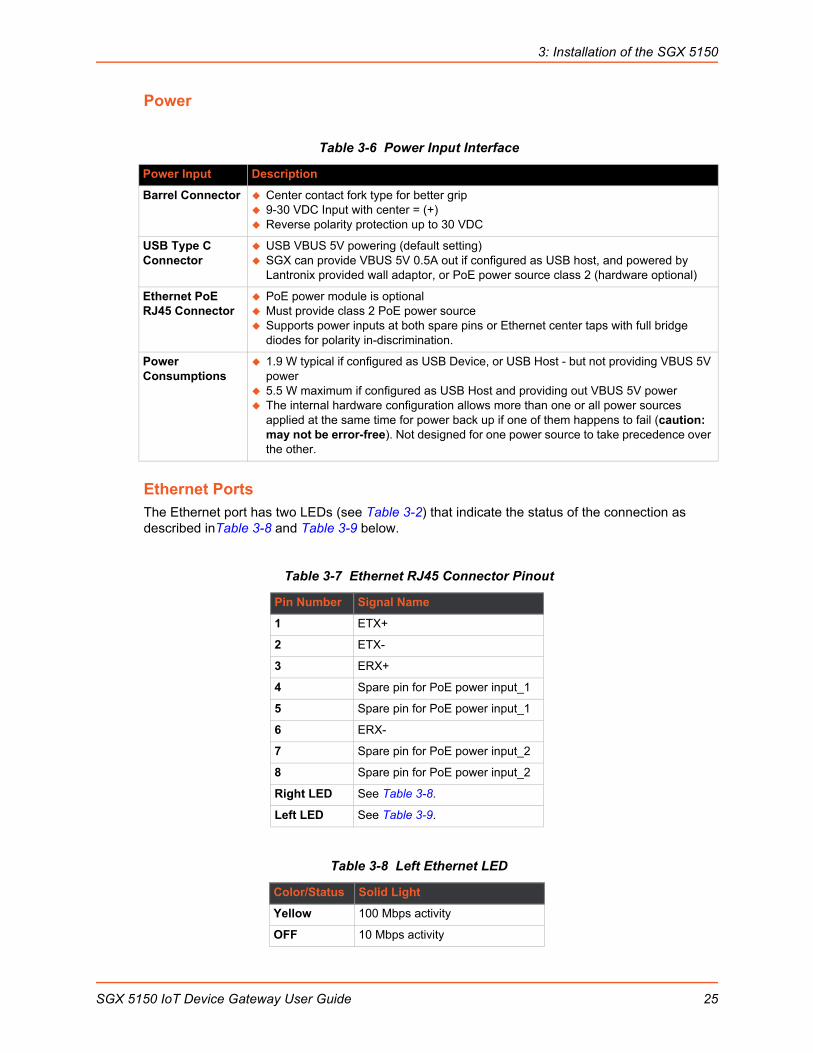
Power
Table 3-6 Power Input Interface
Ethernet PortsThe Ethernet port has two LEDs (see Table 3-2) that indicate the status of the connection as described inTable 3-8 and Table 3-9 below.
Table 3-7 Ethernet RJ45 Connector Pinout
Table 3-8 Left Ethernet LED
Power Input Description
Barrel Connector Center contact fork type for better grip 9-30 VDC Input with center = (+) Reverse polarity protection up to 30 VDC
USB Type C Connector
USB VBUS 5V powering (default setting) SGX can provide VBUS 5V 0.5A out if configured as USB host, and powered by
Lantronix provided wall adaptor, or PoE power source class 2 (hardware optional)
Ethernet PoE RJ45 Connector
PoE power module is optional Must provide class 2 PoE power source Supports power inputs at both spare pins or Ethernet center taps with full bridge
diodes for polarity in-discrimination.
Power Consumptions
1.9 W typical if configured as USB Device, or USB Host - but not providing VBUS 5V power
5.5 W maximum if configured as USB Host and providing out VBUS 5V power The internal hardware configuration allows more than one or all power sources
applied at the same time for power back up if one of them happens to fail (caution: may not be error-free). Not designed for one power source to take precedence over the other.
Pin Number Signal Name
1 ETX+
2 ETX-
3 ERX+
4 Spare pin for PoE power input_1
5 Spare pin for PoE power input_1
6 ERX-
7 Spare pin for PoE power input_2
8 Spare pin for PoE power input_2
Right LED See Table 3-8.
Left LED See Table 3-9.
Color/Status Solid Light
Yellow 100 Mbps activity
OFF 10 Mbps activity
SGX 5150 IoT Device Gateway User Guide 25

3: Installation of the SGX 5150
Table 3-9 Right Ethernet LED
The Ethernet port can conect to an Ethernet (10 Mbps) or fast Ethernet (100 Mbps) network.
Table 3-10 WLAN Signal Strength Indicator at 2.4 GHz
Table 3-11 WLAN Signal Strength Indicator at 5 GHz
Wi-Fi Protected Setup (WPS)Using WPS, you have the option of connecting to SGX 5150 devices with a router or access point in a single operation instead of manually creating a profile with a network name (SSID), setting up wireless security parameters and updating the choice list.
Figure 3-12 Wi-Fi Protected Setup
Color/Status Blinking Light
Green Link Up
OFF No Link
Fault Conditions Blink Pattern
Greater than -60 dbM 3
Greater than -70 dbM and less than -60 dbM 2
Greater than -80 dbM and less than -70 dbM 1
Less than -80 dBm All OFF
Fault Conditions Blink Pattern
Greater than -60 dbM 3
Greater than -65 dbM and less than -60 dbM 2
Greater than -70 dbM and less than -65 dbM 1
Less than -70 dBm All OFF
WPSButton
WLAN & WPS Status Indicator
SGX 5150 IoT Device Gateway User Guide 26

3: Installation of the SGX 5150
Table 3-13 WPS Status Indicator
The WLAN link LED is used to indicate WPS status. See below for blink patterns.
Notes:
For Table 3-11 above, a “long” blink is 0.7 seconds of light followed by 0.3 seconds of no light. A “short” blink is a light that is on for only 0.2 seconds and followed by 0.2 seconds of no light.
The diagnostic blink patterns reflect the highest priority fault condition. Also, the Diagnostic LED will give an initial, identifying blink pattern to indicate the type of diagnostic information it will display. All power and other non-network related diagnostic patterns begin with one long blink. All wired LAN related diagnostics patterns begin with two long blinks. All WLAN-related diagnostics patterns begin with three long blinks.
Reset ButtonPress the Reset button as shown in Figure 3-1 for 6 seconds to reset the SGX 5150 configuration parameters to factory defaults and reboot.
To Start WPS
Using the Device
1. Place the end of a paper clip or similar object into the WPS opening (see Figure 3-12) and press and hold down for a minimum of 5 seconds.
2. Remove the paper clip to release the button. The unit will start Wi-Fi protected setup.
Installing the SGX 5150
Be sure to place or mount the device securely on a flat horizontal or vertical surface. The device comes with brackets for mounting it, for example, on a wall. If using AC power, do not use outlets controlled by a wall switch.
Observe the following guidelines when connecting the serial devices:
The SGX 5150 serial ports support RS-232 or multi-protocol RS232/422/485 serial ports.
Use a null modem cable to connect the serial port to another DTE device. Use a straight-though (modem) cable to connect the serial port to a DCE device.
Connect your RJ-45 Ethernet cable to the RJ-45 port of the unit.
Perform the following steps to install your device:
1. Attach the two antennas to the device.
2. Connect the equipment to the numbered device port (Serial 1/Serial 2) using appropriate cables and adapters.
WPS Status Blink Pattern
WPS is enabled and on Short, continuous
WPS has a profile error Long, long, long, short, short, 2 seconds off, continuous
WPS has a timeout error Long, long, long, short, short, short, short, 2 seconds off, continuous
SGX 5150 IoT Device Gateway User Guide 27
3: Installation of the SGX 5150
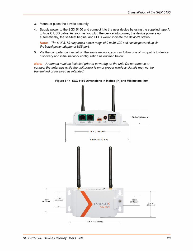
3. Mount or place the device securely.
4. Supply power to the SGX 5150 and connect it to the user device by using the supplied tape A to type C USB cable. As soon as you plug the device into power, the device powers up automatically, the self-test begins, and LEDs would indicate the device's status.
Note: The SGX 5150 supports a power range of 9 to 30 VDC and can be powered up via the barrel-power adapter or USB port.
5. Via the computer connected on the same network, you can follow one of two paths to device discovery and initial network configuration as outlined below.
Note: Antennas must be installed prior to powering on the unit. Do not remove or connect the antennas while the unit power is on or proper wireless signals may not be transmitted or received as intended.
Figure 3-14 SGX 5150 Dimensions in Inches (in) and Millimeters (mm)
SGX 5150 IoT Device Gateway User Guide 28

3: Installation of the SGX 5150
Optional SGX 5150 Bracket
A bracket accessory for securing the SGX 5150 IoT device gateway can be purchased at the Lantronix Online Store at https://store.lantronix.com/ or by calling Lantronix Sales at 800-422-7055. Purchased brackets will come with an installation guide.
Figure 3-15 Optional Bracket Installation
SGX 5150 IoT Device Gateway User Guide 29

3: Installation of the SGX 5150
Wireless Quick Connect
Continue with these steps for Wireless Quick Connect after installing the SGX 5150 IoT device gateway.
1. From your Wi-Fi device, connect to SSID sgx5150_*, where * is your gateway 12-digit serial number.
2. From your browser, connect to 192.168.0.1 using these login credentials:
User ID = admin
Password = PASS
Note: For security purposes, please change the admin password during initial setup.
3. Select Wireless Quick Connect, choose the appropriate network name for the gateway connection, and follow the prompts for your wireless network required security parameters.
4. Click Apply to save and complete the wireless network setup.
SGX 5150 IoT Device Gateway User Guide 30
4: Using DeviceInstaller
This chapter covers the steps for getting the SGX 5150 unit online and for viewing its current configuration though the Lantronix DeviceInstaller application. DeviceInstaller is a free utility program that discovers, configures, upgrades, and manages Lantronix devices. It can be downloaded from the Lantronix website at www.lantronix.com/support/downloads.
For instructions on using DeviceInstaller to configure the IP address and related settings or for more advanced features, see the DeviceInstaller Online Help.
Note: Auto IP generates a random IP address in the range of 169.254.0.1 to 169.254.255.254, with a netmask of 255.255.0.0, if no BOOTP or DHCP server is found. These addresses are not routable.
Installing DeviceInstaller
1. Download the latest version of Lantronix DeviceInstaller application from: www.lantronix.com/support/downloads.
2. Run the executable to start the installation process.
3. Respond to the installation wizard prompts. (If prompted to select an installation type, select Typical.)
Accessing the SGX 5150 Using DeviceInstaller
Note: Make note of the MAC address on your SGX 5150 unit. It may be needed to perform various functions in the DeviceInstaller application.
1. Click StartAll Programs Lantronix DeviceInstaller 4.4 DeviceInstaller.
2. When DeviceInstaller starts, it will perform a network device search. To perform another search, click Search.
3. Expand the SGX folder by clicking the + symbol next to the folder icon. A list of available Lantronix SGX 5150 units appears.
4. Select a SGX 5150 unit by expanding its entry and clicking on its IP address to view its configuration.
5. On the right page, click the Device Info tab. The current SGX 5150 configuration appears. This is only a subset of the full configuration; the full configuration may be accessed via Web Manager, CLI, or XML.
SGX 5150 IoT Device Gateway User Guide 31

4: Using DeviceInstaller
Table 4-1 SGX 5150 Configuration in DeviceInstaller
Current Settings Description
Name Configurable field. A name that identifies the SGX 5150 unit. The name field is blank by default. Double-click the field, type in the value, and press Enter to complete. This name is not visible on other PCs or laptops using DeviceInstaller.
DHCP Device Name Non-configurable field. Displays the name associated with SGX 5150 unit’s current IP address, if the IP address was obtained dynamically.
To change the DHCP device name, see Chapter 5: Configuration Using Web Manager or see the SGX 5150 IoT Device Gateway Command Reference available at www.lantronix.com/support/documentation.
Group Configurable field. A group name to categorize the SGX 5150 unit. Double-click the field, type in the value, and press Enter to complete. This group name is not visible on other PCs or laptops using DeviceInstaller.
Comments Configurable field. Information about the SGX 5150 unit. Double-click the field, type in the value, and press Enter to complete. This description or comment is not visible on other PCs or laptops using DeviceInstaller.
Device Family Non-configurable field. Displays the SGX 5150 units device family as “SGX.”
Short Name Shows “sgx5150” by default.
Long Name Shows “Lantronix SGX5150” by default.
Type Non-configurable field. Displays the device type as “SGX 5150.”
ID Non-configurable field. Displays the SGX 5150 unit’s ID embedded within the unit.
Hardware Address Non-configurable field. Displays the SGX 5150 unit’s hardware (or MAC) address.
Firmware Version Non-configurable field. Displays the firmware currently installed on the SGX 5150 unit.
Extended Firmware Version
Non-configurable field. Displays the full version nomenclature of the firmware.
Online Status Non-configurable field. Displays the SGX 5150 unit’s status as Online, Offline, Unreachable (if the unit is on a different subnet), or Busy (the SGX 5150 unit is currently performing a task.)
IP Address Non-configurable field. Displays the SGX 5150 unit’s current IP address. To change the IP address, click the Assign IP button on the DeviceInstaller menu bar.
IPV6 Link Local Address Non-configurable field. Displays the SGX 5150 unit’s current IPv6 address. To change the IPv6 address, click the Assign IP button on the DeviceInstaller menu bar.
IPV6 Global Address Non-configurable field. Displays the SGX 5150 unit’s global address.
IP Address was Obtained
Non-configurable field. Displays “Dynamically” if the SGX 5150 unit automatically received an IP address (e.g., from DHCP). Displays “Statistically” if the IP address was configured manually. If the IP address was assigned dynamically, the following fields appear:
Obtain with DHCP with value of True or False Obtain with BOOTP with value of True or False
Subnet Mask Non-configurable field. Displays the SGX 5150 unit’s current subnet mask. To change the subnet mask, click the Assign IP button on the DeviceInstaller menu bar.
SGX 5150 IoT Device Gateway User Guide 32

4: Using DeviceInstaller
Next StepNow that the SGX 5150 unit has an IP address and other initial settings, you can configure it.
1. Double-click the unit in the list. Details about the unit display.
2. You have the following options:
To configure the unit using a Web browser, click the Web Configuration tab. The Lantronix Web Manager window displays in your browser. Continue with Chapter 5: Configuration Using Web Manager.
To configure the unit using a Telnet session, click the Telnet Configuration tab. The Setup Mode window displays. See the SGX 5150 IoT Device Gateway Command Reference (available at www.lantronix.com/support/documentation) for directions on configuring the SGX 5150 unit using Command Line Interface (CLI) and/or Extensible Markup Language (XML).
Gateway Non-configurable field. Displays the SGX 5150 unit’s current gateway. To change the default gateway, click the Assign IP button on the DeviceInstaller menu bar.
Interfaces Non-configurable field. Displays the status of the wired (eth0), wireless (wlan0), and usb (usb0) interfaces. Click the plus icon to expand eth0, wlan, or usb0 and see specific interfaces organized beneath each.
Number of Serial Ports Non-configurable field. Displays the number of serial ports on the SGX 5150 unit.
Supports Configurable Pins
Non-configurable field. Displays False.
Supports Email Triggers Non-configurable field. Displays True.
Telnet Supported Non-configurable field. Indicates if Telnet sessions are permitted. Displays True.
Telnet Port Non-configurable field. Displays the SGX 5150 unit’s port for Telnet sessions.
Web Port Non-configurable field. Displays the SGX 5150 unit’s port for Web Manager configuration.
Firmware Upgradable Non-configurable field. Displays True, indicating the SGX 5150 firmware is upgradable as newer version become available.
Current Settings Description
SGX 5150 IoT Device Gateway User Guide 33

5: Configuration Using Web Manager
This chapter describes how to configure the SGX 5150 unit using Web Manager, the Lantronix browser-based configuration tool. The device’s configuration is stored in non-volatile memory and is retained across device reset and during loss of power to the device. All changes take effect immediately, unless otherwise noted. This chapter contains the following sections:
Accessing Web Manager
Status Page
Web Manager Components
Navigating Web Manager
Accessing Web Manager
Web Manager is normally accessed through a standard web browser but you can also access Web Manager in two other ways. See Chapter 4: Using DeviceInstaller on page 31 for additional information on accessing Web Manager through the DeviceInstaller Web Configuration tab. See the SGX 5150 IoT Device Gateway Quick Start Guide for instructions on accessing Web Manager through SoftAP. The quick start guide is available at www.lantronix.com/support/documentation.
To access Web Manager through a web browser:
1. Open a standard web browser. Lantronix supports the latest versions of Internet Explorer®, Firefox®, Safari®, or Chrome™ web browsers.
2. Enter the IP address or host name of the SGX 5150 unit in the address bar. The IP address may have been assigned manually using DeviceInstaller (see Chapter 4: Using DeviceInstaller on page 31) or automatically by DHCP.
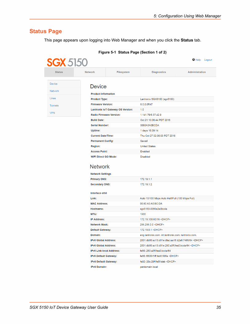
3. Enter your username and password. The factory-default username is “admin” and “PASS” is the default password. The Status web page (see Figure 5-1) displays current configuration and status details for the device, network and line settings.
SGX 5150 IoT Device Gateway User Guide 34
5: Configuration Using Web Manager
Status Page
This page appears upon logging into Web Manager and when you click the Status tab.
Figure 5-1 Status Page (Section 1 of 2)
SGX 5150 IoT Device Gateway User Guide 35
5: Configuration Using Web Manager
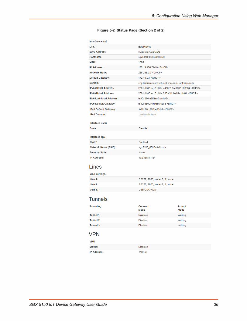
Figure 5-2 Status Page (Section 2 of 2)
SGX 5150 IoT Device Gateway User Guide 36

5: Configuration Using Web Manager
Web Manager Components
The layout of a typical Web Manager page is below.
Figure 5-3 Components of the Web Manager Page
Web Manager pages have these sections:
The Status, Network, Diagnostics and Administration tabs located in the header at the top of the page provide direct access to each Web Manager page of the same name. All the functionality is accessible through Web Manager and is divided between these tab/pages.
Each Web Manager page accessed through the header tabs reveal a page-specific menu bar on the left side organizing available sections for that page.
The menu bar accessed via the Network and Administration tabs contain selections that can further expand to reveal additional subsections. A right-pointing blue arrow indicates a particular selection can be expanded to reveal subsections.
Expand or collapse an expandable menu bar section by clicking on it.
The main body area of the page contains either view-only Status info or Configuration options according to the tab, menu bar selection or subsection selected.
When a parameter is changed on a page, a Submit button will appear at the bottom of the page. Click on this button to save the change.
A Logout link is available at the upper right corner of every Setup and Admin page. In Chrome or Safari, it is necessary to close out of the browser to completely logout. If necessary, reopen the browser to log back in.
Header
Menu Bar
Status and/orConfiguration Area
These selections can expand to reveal additional subsections
Expanded
Figure 5-4 Expandable Menu Bar Selections
SGX 5150 IoT Device Gateway User Guide 37
5: Configuration Using Web Manager
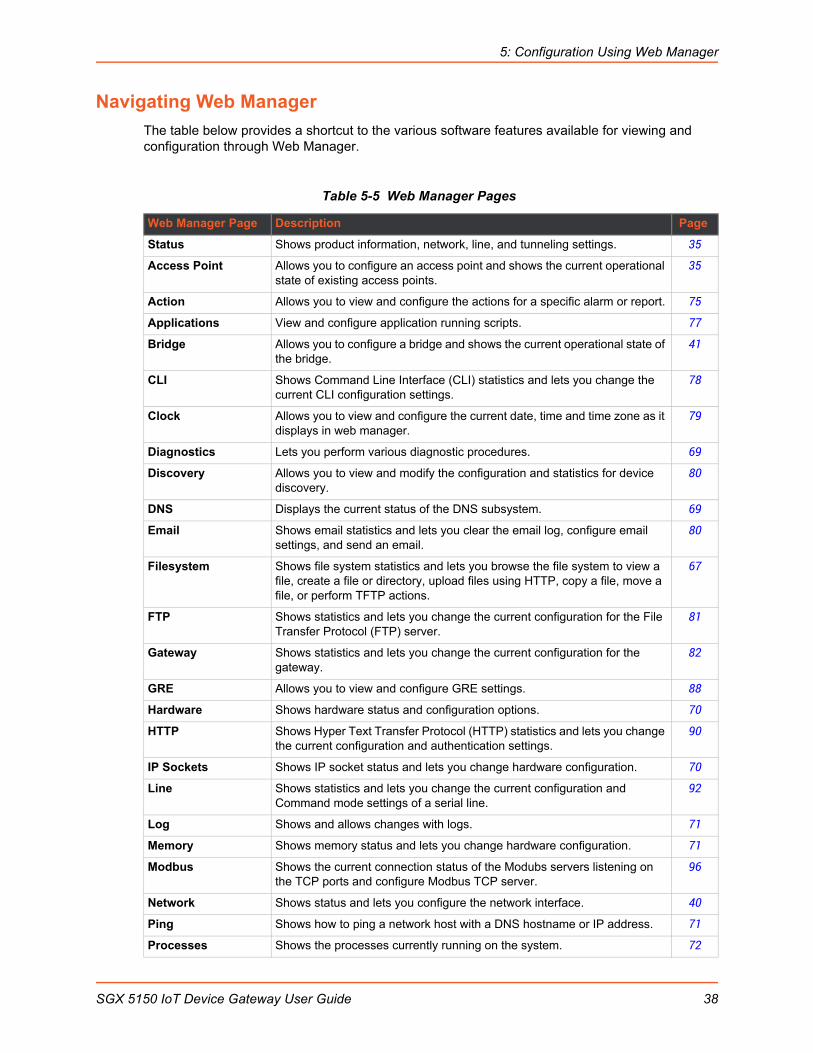
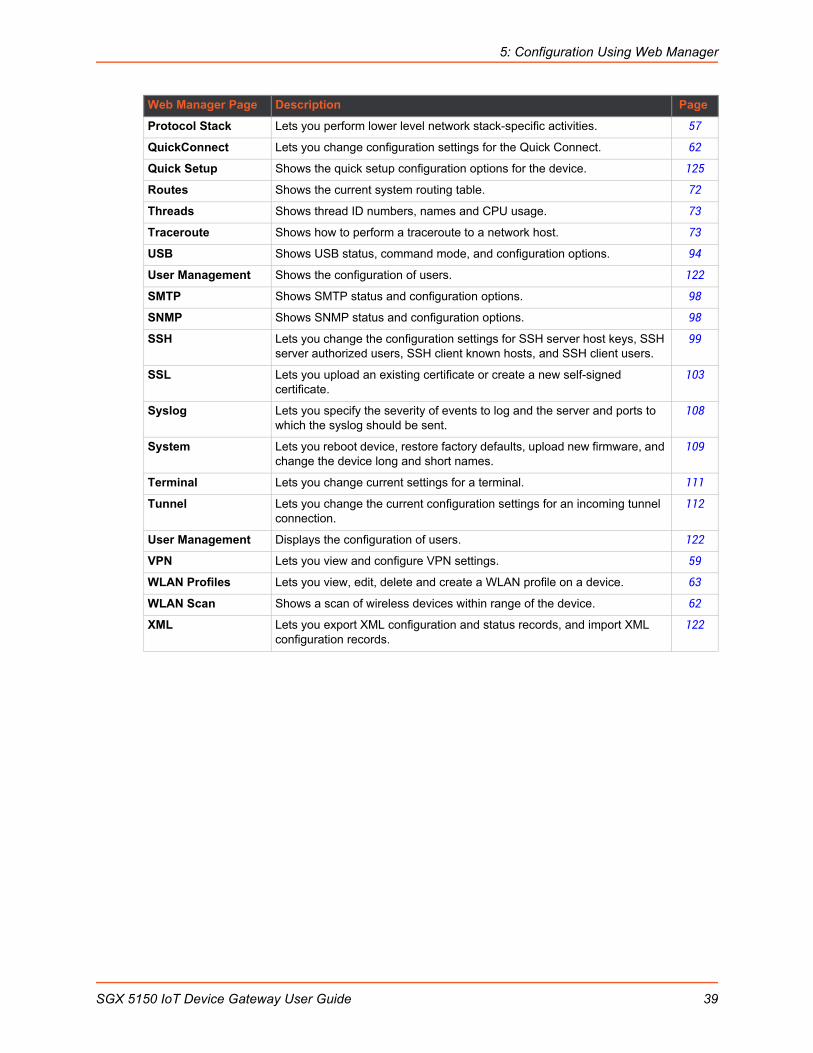
Navigating Web Manager
The table below provides a shortcut to the various software features available for viewing and configuration through Web Manager.
Table 5-5 Web Manager Pages
Web Manager Page Description Page
Status Shows product information, network, line, and tunneling settings. 35
Access Point Allows you to configure an access point and shows the current operational state of existing access points.
35
Action Allows you to view and configure the actions for a specific alarm or report. 75
Applications View and configure application running scripts. 77
Bridge Allows you to configure a bridge and shows the current operational state of the bridge.
41
CLI Shows Command Line Interface (CLI) statistics and lets you change the current CLI configuration settings.
78
Clock Allows you to view and configure the current date, time and time zone as it displays in web manager.
79
Diagnostics Lets you perform various diagnostic procedures. 69
Discovery Allows you to view and modify the configuration and statistics for device discovery.
80
DNS Displays the current status of the DNS subsystem. 69
Email Shows email statistics and lets you clear the email log, configure email settings, and send an email.
80
Filesystem Shows file system statistics and lets you browse the file system to view a file, create a file or directory, upload files using HTTP, copy a file, move a file, or perform TFTP actions.
67
FTP Shows statistics and lets you change the current configuration for the File Transfer Protocol (FTP) server.
81
Gateway Shows statistics and lets you change the current configuration for the gateway.
82
GRE Allows you to view and configure GRE settings. 88
Hardware Shows hardware status and configuration options. 70
HTTP Shows Hyper Text Transfer Protocol (HTTP) statistics and lets you change the current configuration and authentication settings.
90
IP Sockets Shows IP socket status and lets you change hardware configuration. 70
Line Shows statistics and lets you change the current configuration and Command mode settings of a serial line.
92
Log Shows and allows changes with logs. 71
Memory Shows memory status and lets you change hardware configuration. 71
Modbus Shows the current connection status of the Modubs servers listening on the TCP ports and configure Modbus TCP server.
96
Network Shows status and lets you configure the network interface. 40
Ping Shows how to ping a network host with a DNS hostname or IP address. 71
Processes Shows the processes currently running on the system. 72
SGX 5150 IoT Device Gateway User Guide 38
5: Configuration Using Web Manager
Protocol Stack Lets you perform lower level network stack-specific activities. 57
QuickConnect Lets you change configuration settings for the Quick Connect. 62
Quick Setup Shows the quick setup configuration options for the device. 125
Routes Shows the current system routing table. 72
Threads Shows thread ID numbers, names and CPU usage. 73
Traceroute Shows how to perform a traceroute to a network host. 73
USB Shows USB status, command mode, and configuration options. 94
User Management Shows the configuration of users. 122
SMTP Shows SMTP status and configuration options. 98
SNMP Shows SNMP status and configuration options. 98
SSH Lets you change the configuration settings for SSH server host keys, SSH server authorized users, SSH client known hosts, and SSH client users.
99
SSL Lets you upload an existing certificate or create a new self-signed certificate.
103
Syslog Lets you specify the severity of events to log and the server and ports to which the syslog should be sent.
108
System Lets you reboot device, restore factory defaults, upload new firmware, and change the device long and short names.
109
Terminal Lets you change current settings for a terminal. 111
Tunnel Lets you change the current configuration settings for an incoming tunnel connection.
112
User Management Displays the configuration of users. 122
VPN Lets you view and configure VPN settings. 59
WLAN Profiles Lets you view, edit, delete and create a WLAN profile on a device. 63
WLAN Scan Shows a scan of wireless devices within range of the device. 62
XML Lets you export XML configuration and status records, and import XML configuration records.
122
Web Manager Page Description Page
SGX 5150 IoT Device Gateway User Guide 39
6: Network Settings
Network settings for the SGX 5150 can be viewed and modified under the Network tab in the Web Manager user interface. This chapter describes the following network settings:
Access Point
Bridge
Wired (eth0) Network
Wireless (wlan0) Network
Wired (usb0) Network
Protocol Stack
VPN
Wi-Fi Protected Setup
WLAN Scan/QuickConnect
WLAN Profiles
Access Point
Configure software-enabled access point interface on this page. Access point status information displays at the bottom half of the page.
Table 6-1 Access Point Settings
To View or Configure Access Point Settings
Using Web Manager
To view access point statistics and configuration options, on the Network page, click Access Point.
Using the CLI
To enter the command level: enable > config > access point
Access Point Field Description
State Select to enable or disable the access point. If enabled, the DHCP server will assign IP addresses to the access point clients.
IP Address Enter the IP address of the SoftAP interface.
Network Name (SSID) Specify the network name/SSID of the access point. The SSID update will take effect after the device is rebooted.
Security Suite Select a security suite to be used with the access point.
Passphrase Enter a passphrase if WPA or WPA2 security suite is selected above.
Note: This field appears when WPA or WPA2 security suite is selected.
Show Password (check box) Check to make the passphrase entered to the left visible.
Note: This field appears when WPA or WPA2 security suite is selected.
SGX 5150 IoT Device Gateway User Guide 40

6: Network Settings
Using XML
Include in your file: <configgroup name=”access point”>
Bridge
The SGX 5150 bridges traffic between an Ethernet or USB RNDIS (usb0) and WLAN interface. For example, br0 is a bridge between eth0 and wlan0. For USB RNDIS interface, USB 1 must be configured as an Ethernet device.
When a bridge is enabled, the Wired (eth0) Network configuration is used for configuring direct connections into the device over the primary interface; the Wireless (wlan0) Network configuration is ignored. Both the Ethernet and WLAN link configurations are used the same as when the bridge is disabled.
Bridging MAC Address specifies the MAC address of bridgeable traffic between the Ethernet and WLAN interfaces. When bridging is active, this MAC Address will be used as the MAC address of the WLAN interface. Packets received on the Ethernet interface from this address will be bridged to the WLAN interface (except traffic directed at the Primary Interface). If this field is not configured, then the device waits for the first packet to arrive on the Ethernet interface and uses the source address as the bridging address.
Bridging IP Address specifies the IP address of the bridged client.
When bridging is active, this IP Address will be used to create a static route between this device and the bridged client.
This route is required for connecting to the bridged client from devices connected via the access point network and from this device.
If Auto Detect IP Address is enabled, then the device will attempt to learn the IP Address by using the source or destination IP address of packets arriving on the Ethernet interface.
Warning: Enabling Auto Detect IP Address may affect the performance of running processes during the learning phase.
During initialization, the bridging subsystem enables and controls both eth0 and wlan0 networks. These are important aspects to keep in mind:
If the eth0 physical link is inactive, wlan0 is the primary interface.
If the eth0 physical link is active, eth0 is the primary interface.
When the eth0 link is active, the wlan0 link is established. Additionally, the bridging MAC address is acquired using preconfiguration or auto-detection, and bridging enters the Active state. If either link goes down, bridging reverts to the Inactive state.
When in the Active state, all packets that arrive on the wlan0 interface are bridged out (through) the eth0 interface. Similarly, all packets that arrive on the eth0 interface are bridged out (through) the wlan0 interface. However, exceptions to this behavior include:
Ethernet packets directed specifically to the Ethernet (eth0) MAC address are terminated internally and are not bridged to WLAN.
An ARP request for the primary interface IP address is terminated internally and is not bridged to the WLAN.
Ethernet packets that do not originate from the bridging MAC Address are discarded.
SGX 5150 IoT Device Gateway User Guide 41

6: Network Settings
Bridge Status and ConfigurationView-only status information on the Bridge1 (br0) Status page displays whether bridging is currently enabled, active, and the following (if any): Ethernet link, WLAN link, primary interface, bridging MAC, Ethernet MAC, WLAN MAC, bridging IP address, and bridging IPv6 address. Ethernet to WLAN and WLAN to Ethernet statistics are provided for unicast, nonunicast, discards and octets.
See Table 6-2 for the bridge settings that can be modified on the Bridge1 (br0) Configuration page.
Table 6-2 Bridge Settings
Bridge Fields Description
State Select to enable or disable bridging. When a bridge is Enabled, the Ethernet Network Interface Configuration is used for configuring direct connections into the device over the primary Interface. The WLAN Network Interface Configuration is ignored. Both the Ethernet and WLAN Link Configurations are used the same as when the bridge is disabled. In Bridge Statistics:
Enable State shows whether the bridge is currently enabled. If the state is changed, it will not be reflected here until the next reboot.
Active State shows the current state of the bridge. The bridge may be Active or Inactive, depending on the state of the bridge and the physical links.
Transparent Mode Select to enable or disable transparent mode.
If Enabled, the SGX 5150 can no longer be accessed via telnet or web manager from a PC and is invisible to the network.
If Disabled, the SGX 5150 will be accessible to a PC on the network via telnet or Web Manager.
Ethernet Interface Select interface from drop-down menu:
eth0 (default) usb0
Bridging MAC Address Enter the bridging MAC address which specifies the MAC address of bridgeable traffic between the Ethernet and WLAN interfaces. When bridging is active, this MAC Address will be used as the MAC address of the WLAN interface. Packets received on the Ethernet interface from this address will be bridged to the WLAN interface (except traffic directed at the primary interface). If this field is not configured, then the device waits for the first packet to arrive on the Ethernet interface and uses the source address as the bridging address.
Bridging IP Address Enter the bridging IP address which specifies the IP address of the bridged client. When bridging is active, this IP address will be used to create a static route between this device and the bridged client. This route is required for connecting to the bridged client from devices connected via the access point network and from this device.
Auto Detect IPv5 Address Select to enable or disable auto-detection of the bridged client’s IP address.
Bridging IPv6 Address Enter the bridging IPv6 address.
SGX 5150 IoT Device Gateway User Guide 42

6: Network Settings
To View or Configure Bridge Settings
Using Web Manager
To view the Bridge status, on the Network page, click Bridge > Statistics.
To configure Bridge settings, on the Network page, click Bridge > Configuration in the links.
Using the CLI
To enter the command level: enable > config > bridge 1
Using XML
Include in your file: <configgroup name=”bridge” instance=”br0”>
Wired (eth0) Network
Network interface settings apply to both the wired Ethernet (eth0) and wireless WLAN (wlan0) interfaces, but are configured independently for each interface. The wired network pages are described in this section.
Interface Status and ConfigurationTable 6-3 displays the wired interface status and configuration information. The view-only status information is available on the Wired (eth0) Network Interface Status page. This same information is configurable on the Wired (eth0) Network Interface Configuration page.
Table 6-3 Wired (eth0) Network Interface
Field/Button Description
State Select to enable or disable the interface
Hostname Enter the hostname for the interface. It must begin with a letter or number, continue with a sequence of letters, numbers, or hyphens, and end with a letter or number.
This setting will take effect immediately, but will not register the hostname with a DNS server until the next reboot.
Priority Priority ranges from 0-10. The IP stack will give the interface with the lowest numerical value highest priority and the highest numerical values lowest priority when sending data. This setting only applies when the device is not in bridging mode and both interfaces are connected to the same IP subnet.
MTU When DHCP is enabled, the MTU size is (usually) provided with the IP address. When not provided by the DHCP server, or using a static configuration, this value is used. The MTU size can be from 576 to 1500 bytes, the default being 1500 bytes.
IPv4 State Select to enable or disable.
SGX 5150 IoT Device Gateway User Guide 43

6: Network Settings
DHCP Client Select to turn On or Off. At boot up, after the physical link is up, the SGX 5150 unit will attempt to obtain IPv4 settings from a DHCP server and will periodically renew these settings with the server.
Note: Overrides the BOOTP client, the configured IPv4 address/mask, gateway, hostname, and domain. Changing this value requires you to reboot the device. Within Web Manager, click Renew to renew the DHCP lease.
IP Address Enter the static IPv4 address to use for the interface. You may enter it alone or in CIDR format.
Note: This setting will be used if Static IP is active (both DHCP and BOOTP are Disabled). Changing this value requires you to reboot the device. When DHCP or BOOTP is enabled, the SGX 5150 unit tries to obtain an IPv4 address from a DHCP or BOOTP server. If it cannot, the SGX 5150 unit generates and uses an Auto IP address in the range of 169.254.xxx.xxx, with a network mask of 255.255.0.0.
Default Gateway Enter the IPv4 address of the router for this network.
Note: This setting will be used if Static IP is active (both DHCP and BOOTP are Disabled).
Domain Enter the domain name suffix for the interface.
Note: This setting will be used when either static IP or auto IP is active, or if DHCP/BOOTP is active and no domain suffix was acquired from the server.
DHCP Client ID Enter the ID if the DHCP server requires a DHCP client ID option. The DHCP server’s lease table shows IP addresses and MAC addresses for devices. The lease table shows the client ID, in hexadecimal notation, instead of the SGX 5150 unit MAC address.
Primary DNS Enter the IP address of the primary domain name server (DNS.)
Note: This setting will be used when either Static IP or Auto IP is active, or if DHCP/BOOTP is active and no DNS server was acquired from the server.
Secondary DNS Enter the IP address of the secondary domain name server.
Note: This setting will be used when either Static IP or Auto IP is active, or if DHCP/BOOTP is active and no DNS server was acquired from the server.
IPv6 State Select to enable or disable.
IPv6 DHCP Client Select to turn On or Off. At bootup, after the physical link is up, the SGX 5150 unit will attempt to obtain IPv6 settings from a DHCPv6 server and will periodically renew these settings with the server.
On: enables the SGX 5150 server to obtain IPv6 setting from a DHCPv6 server upon bootup.
Off: enables the SGX 5150 server to obtain IPv4 settings from a DHCP server upon bootup.
Note: Overrides the configured IP address/mask, gateway, hostname, and domain. Changing this value requires you to reboot the device. Within Web Manager, click Renew to renew the DHCPV6 lease.
IPv6 Auto Configuration
Select to turn On or Off IPv6 auto configuration.
IPv6 IP Address Enter the static IPv6 address to use for the interface.
Note: This setting is used if Static IPv6 is active (DHCPv6 is Disabled). Changing this value requires a reboot. When DHCPv6 is enabled, the SGX 5150 unit tries to obtain an IPv6 address from a DHCPv6 server. If it cannot, then SGX 5150 unit generates and uses a Link local IPv6 address.
Field/Button Description
SGX 5150 IoT Device Gateway User Guide 44

6: Network Settings
To Configure Network Interface Settings
Using Web Manager
To view Ethernet (eth0) Interface statistics, on the Network page, select Wired Network > Interface.
To configure Ethernet (eth0) interface settings, on the Network page, select Wired Network > Interface > Configuration.
Using the CLI
To enter the command level: enable > config > if 1
Using XML
Include in your file: <configgroup name= “interface" instance="eth0">
Link Status and ConfigurationTable 6-4 displays the wired link status and configuration information. The view-only status information is available on the Wired (eth0) Network Ethernet Link page. This same information is configurable on the Wired (eth0) Network Ethernet Link Configuration page.
Table 6-4 Link (eth0) Configuration
Notes:
When speed is Auto, duplex must be Auto or Half.
When speed is not Auto, duplex must be Half or Full.
IPv6 Default Gateway Enter the default IPv6 default gateway.
IPv6 Domain Enter the domain name suffix for the interface.
Note: This setting will be used when either Static IP or Auto IP is active, or if DHCP/BOOTP is active and no Domain Suffix was acquired from the server.
IPv6 Primary DNS Enter the IP address of the primary domain name server.
Note: This setting will be used when either Static IP or Auto IP is active, or if DHCP/BOOTP is active and no DNS server was acquired from the server.
IPv6 Secondary DNS Enter the IP address of the secondary domain name server.
Note: This setting will be used when either Static IP or Auto IP is active, or if DHCP/BOOTP is active and no DNS server was acquired from the server.
Field/Button Description
Speed Select the Ethernet link speed. (Default is Auto.)
Auto = Auto-negotiation of Link Speed 10 Mbps = Force 10 Mbps 100 Mbps = Force 100 Mbps
Duplex Select the Ethernet link duplex mode. (Default is Auto.)
Auto = Auto-negotiation of Link Duplex Half = Force Half Duplex Full = Force Full Duplex
Field/Button Description
SGX 5150 IoT Device Gateway User Guide 45

6: Network Settings
Fixed-speed Full duplex produces errors when connected to Auto, due to duplex mismatch.
To Configure Network Link Settings
Using Web Manager
To view Ethernet (eth0) link statistics, on the Network page, select Wired Network > Link.
To configure Ethernet (eth0) link settings, on the Network page, select Wired Network > Link > Configuration.
Using the CLI
To enter the command level: enable > config > if 1 > link
Using XML
Include in your file: <configgroup name= “interface" instance="eth0">
QoS Statistics and ConfigurationQoS (Quality of Service) can be enabled and configured for both the Wireless (wlan0) Network and wired Network (eth0). If enabled, the router will control the flow of outbound traffic according to the user-defined filters. In other words, QoS improves performance by allowing the user to prioritize applications. Filters can be defined to prioritize traffic based on the source or destination network, source or destination port, or the source MAC address. Up to 32 user-defined filters can be added. The following are predefined priority classes:
Network Control and Internetwork Control are typically used for network control packets such as ICMP and have the highest priorities.
Move bandwidth allocation is a minimum 5% each to Network control.
Voice: Bandwidth allocation is minimum 30%.
Video: Bandwidth allocation is minimum 20%.
Critical Applications: Bandwidth allocation is minimum 15%.
Excellent Effort: Bandwidth allocation is minimum 10%.
Best Effort: Bandwidth allocation is minimum 10%.
Background: Bandwidth allocation is minimum 5% and has the lowest priority.
Table 6-5 Wired (eth0) Network QoS Settings shows the network QoS settings that can be configured including adding new filters.
Table 6-5 Wired (eth0) Network QoS Settings
Wired (eth0) Network Settings
Description
State Click to enable or disable state.
Import filters Click to enable or disable import filters to import configurations from other interfaces.
Uplink Speed Enter the maximum uplink speed. Set 0 to set speed to default.
Delete Click the checkbox to the left of any existing QoS filter to be deleted and click the Submit button.
SGX 5150 IoT Device Gateway User Guide 46

6: Network Settings
To View and Configure Wired Network QoS Settings
Using Web Manager
To view Ethernet (eth0) QoS statistics, click Network on the menu and select Wired Network > QoS.
To modify Ethernet (eth0) QoS information, click Network on the menu and select Wired Network > QoS > Configuration.
Using the CLI
To enter the eth0 QoS command level: enable > config > if 1 > qos
Using XML
Include in your file: <configgroup name="ethernet" instance="eth0">
Wired (eth0) Network FailoverThe SGX 5150 device gateway provides WAN network failover, in the form of a "dead remote host reachability" mechanism (essentially a ping against a known host). If the remote host is determined to be not reachable, the device will failover to the Wi-Fi interface. If the remote host is determined to be reachable, the device will failback to the Ethernet interface.
Table 6-6 Wired (eth0) Network Failover Settings
Filter type Select the filter type from the drop-down window:
Network Port
Network Enter the Network, if the Network filter type is selected.
Ports Enter the Port, if the Port filter type is selected.
Priority Select the priority of the filter from the drop-down menu.
Wired Network (Failover) Settings
Description
State Click to enable or disable state.
Failover Interface Always select wlan0 in the SGX 5150 device gateway.
Hostname Enter the remote host to test reachability.
Method Select ICMP or TCP based ping.
Timeout Indicate the interval to wait for ping response from remote host.
Interval Indicate the interval in which to test reachability
Failover Threshold Indicate the allowed number of failed pings – after which the device will failover to the wlan0 interface.
Failback Threshold Indicate the number of successful pings – after which the device will failback to the Ethernet interface.
Wired (eth0) Network Settings
Description
SGX 5150 IoT Device Gateway User Guide 47
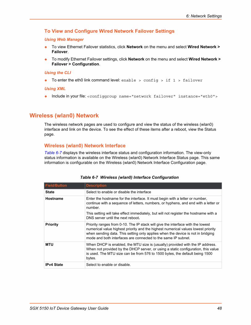
6: Network Settings
To View and Configure Wired Network Failover Settings
Using Web Manager
To view Ethernet Failover statistics, click Network on the menu and select Wired Network > Failover.
To modify Ethernet Failover settings, click Network on the menu and select Wired Network > Failover > Configuration.
Using the CLI
To enter the eth0 link command level: enable > config > if 1 > failover
Using XML
Include in your file: <configgroup name="network failover" instance="eth0">
Wireless (wlan0) Network
The wireless network pages are used to configure and view the status of the wireless (wlan0) interface and link on the device. To see the effect of these items after a reboot, view the Status page.
Wireless (wlan0) Network InterfaceTable 6-7 displays the wireless interface status and configuration information. The view-only status information is available on the Wireless (wlan0) Network Interface Status page. This same information is configurable on the Wireless (wlan0) Network Interface Configuration page.
Table 6-7 Wireless (wlan0) Interface Configuration
Field/Button Description
State Select to enable or disable the interface
Hostname Enter the hostname for the interface. It must begin with a letter or number, continue with a sequence of letters, numbers, or hyphens, and end with a letter or number.
This setting will take effect immediately, but will not register the hostname with a DNS server until the next reboot.
Priority Priority ranges from 0-10. The IP stack will give the interface with the lowest numerical value highest priority and the highest numerical values lowest priority when sending data. This setting only applies when the device is not in bridging mode and both interfaces are connected to the same IP subnet.
MTU When DHCP is enabled, the MTU size is (usually) provided with the IP address. When not provided by the DHCP server, or using a static configuration, this value is used. The MTU size can be from 576 to 1500 bytes, the default being 1500 bytes.
IPv4 State Select to enable or disable.
SGX 5150 IoT Device Gateway User Guide 48

6: Network Settings
DHCP Client Select to turn On or Off. At boot up, after the physical link is up, the SGX 5150 unit will attempt to obtain IPv4 settings from a DHCP server and will periodically renew these settings with the server.
Note: Overrides BOOTP, the configured IPv4 address/mask, gateway, hostname, and domain. Changing this value requires you to reboot the device. Within Web Manager, click Renew to renew the DHCP lease.
IP Address Enter the static IPv4 address to use for the interface. You may enter it alone or in CIDR format.
Note: This setting will be used if Static IP is active (both DHCP and BOOTP are Disabled). Changing this value requires you to reboot the device. When DHCP or BOOTP is enabled, the SGX 5150 unit tries to obtain an IPv4 address from a DHCP or BOOTP server. If it cannot, the SGX 5150 unit generates and uses an Auto IP address in the range of 169.254.xxx.xxx, with a network mask of 255.255.0.0.
Default Gateway Enter the IPv4 address of the router for this network.
Note: This setting will be used if Static IP is active (both DHCP and BOOTP are Disabled).
Domain Enter the domain name suffix for the interface.
Note: This setting will be used when either Static IP or Auto IP is active, or if DHCP/BOOTP is active and no Domain Suffix was acquired from the server.
DHCP Client ID Enter the ID if the DHCP server requires a DHCP Client ID option. The DHCP server’s lease table shows IP addresses and MAC addresses for devices. The lease table shows the client ID, in hexadecimal notation, instead of the SGX 5150 device MAC address.
Primary DNS Enter the IP address of the primary domain name server
Note: This setting will be used when either Static IP or Auto IP is active, or if DHCP/BOOTP is active and no DNS server was acquired from the server.
Secondary DNS Enter the IP address of the secondary domain name server.
Note: This setting will be used when either Static IP or Auto IP is active, or if DHCP/BOOTP is active and no DNS server was acquired from the server.
IPv6 State Select to enable or disable.
IPv6 DHCP Client Select to turn On or Off. At bootup, after the physical link is up, the SGX 5150 unit will attempt to obtain IPv6 settings from a DHCPv6 server and will periodically renew these settings with the server.
On: enables the SGX 5150 server to obtain IPv6 setting from a DHCPv6 server upon bootup.
Off: enables the SGX 5150 server to obtain IPv4 settings from a DHCP server upon bootup.
Note: Overrides the configured IP address/mask, gateway, hostname, and domain. Changing this value requires you to reboot the device. Within Web Manager, click Renew to renew the DHCPV6 lease.
IPv6 Auto Configuration
Select to turn On or Off IPv6 auto configuration.
IPv6 IP Address Enter the static IPv6 address to use for the interface.
Note: This setting is used if Static IPv6 is active (DHCPv6 is Disabled). Changing this value requires a reboot. When DHCPv6 is enabled, the SGX 5150 unit tries to obtain an IPv6 address from a DHCPv6 server. If it cannot, then SGX 5150 unit generates and uses a Link local IPv6 address.
Field/Button Description
SGX 5150 IoT Device Gateway User Guide 49
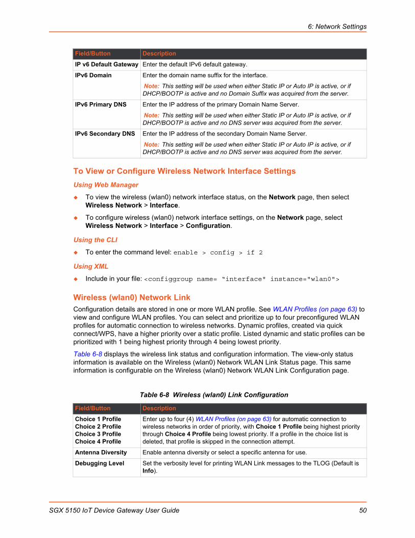
6: Network Settings
To View or Configure Wireless Network Interface Settings
Using Web Manager
To view the wireless (wlan0) network interface status, on the Network page, then select Wireless Network > Interface.
To configure wireless (wlan0) network interface settings, on the Network page, select Wireless Network > Interface > Configuration.
Using the CLI
To enter the command level: enable > config > if 2
Using XML
Include in your file: <configgroup name= “interface" instance="wlan0">
Wireless (wlan0) Network LinkConfiguration details are stored in one or more WLAN profile. See WLAN Profiles (on page 63) to view and configure WLAN profiles. You can select and prioritize up to four preconfigured WLAN profiles for automatic connection to wireless networks. Dynamic profiles, created via quick connect/WPS, have a higher priority over a static profile. Listed dynamic and static profiles can be prioritized with 1 being highest priority through 4 being lowest priority.
Table 6-8 displays the wireless link status and configuration information. The view-only status information is available on the Wireless (wlan0) Network WLAN Link Status page. This same information is configurable on the Wireless (wlan0) Network WLAN Link Configuration page.
Table 6-8 Wireless (wlan0) Link Configuration
IP v6 Default Gateway Enter the default IPv6 default gateway.
IPv6 Domain Enter the domain name suffix for the interface.
Note: This setting will be used when either Static IP or Auto IP is active, or if DHCP/BOOTP is active and no Domain Suffix was acquired from the server.
IPv6 Primary DNS Enter the IP address of the primary Domain Name Server.
Note: This setting will be used when either Static IP or Auto IP is active, or if DHCP/BOOTP is active and no DNS server was acquired from the server.
IPv6 Secondary DNS Enter the IP address of the secondary Domain Name Server.
Note: This setting will be used when either Static IP or Auto IP is active, or if DHCP/BOOTP is active and no DNS server was acquired from the server.
Field/Button Description
Choice 1 ProfileChoice 2 ProfileChoice 3 ProfileChoice 4 Profile
Enter up to four (4) WLAN Profiles (on page 63) for automatic connection to wireless networks in order of priority, with Choice 1 Profile being highest priority through Choice 4 Profile being lowest priority. If a profile in the choice list is deleted, that profile is skipped in the connection attempt.
Antenna Diversity Enable antenna diversity or select a specific antenna for use.
Debugging Level Set the verbosity level for printing WLAN Link messages to the TLOG (Default is Info).
Field/Button Description
SGX 5150 IoT Device Gateway User Guide 50
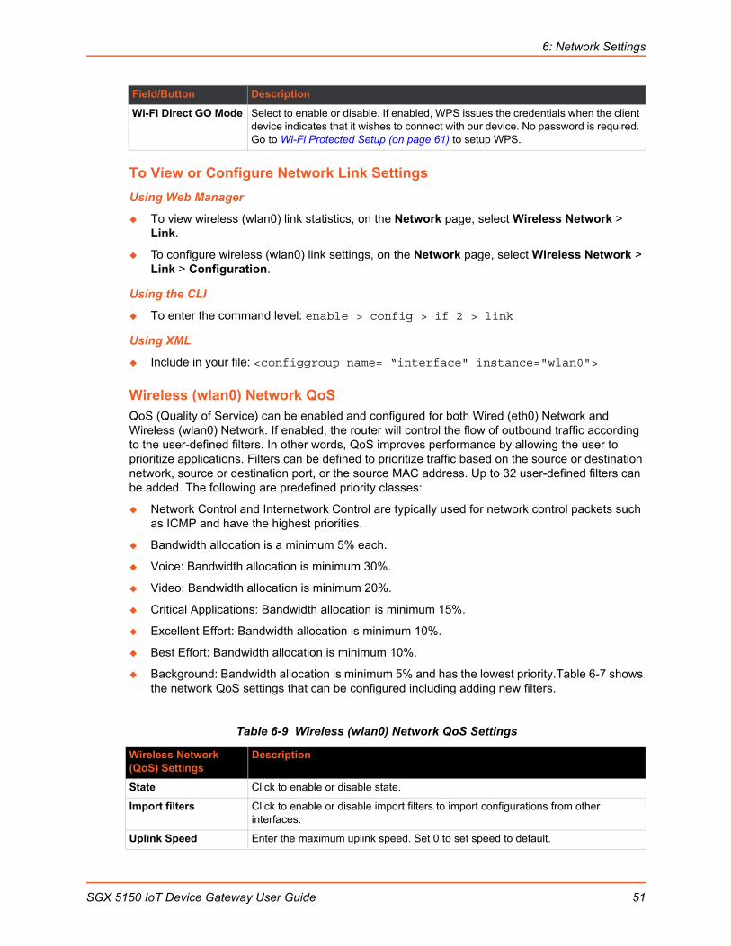
6: Network Settings
To View or Configure Network Link Settings
Using Web Manager
To view wireless (wlan0) link statistics, on the Network page, select Wireless Network > Link.
To configure wireless (wlan0) link settings, on the Network page, select Wireless Network > Link > Configuration.
Using the CLI
To enter the command level: enable > config > if 2 > link
Using XML
Include in your file: <configgroup name= “interface" instance="wlan0">
Wireless (wlan0) Network QoSQoS (Quality of Service) can be enabled and configured for both Wired (eth0) Network and Wireless (wlan0) Network. If enabled, the router will control the flow of outbound traffic according to the user-defined filters. In other words, QoS improves performance by allowing the user to prioritize applications. Filters can be defined to prioritize traffic based on the source or destination network, source or destination port, or the source MAC address. Up to 32 user-defined filters can be added. The following are predefined priority classes:
Network Control and Internetwork Control are typically used for network control packets such as ICMP and have the highest priorities.
Bandwidth allocation is a minimum 5% each.
Voice: Bandwidth allocation is minimum 30%.
Video: Bandwidth allocation is minimum 20%.
Critical Applications: Bandwidth allocation is minimum 15%.
Excellent Effort: Bandwidth allocation is minimum 10%.
Best Effort: Bandwidth allocation is minimum 10%.
Background: Bandwidth allocation is minimum 5% and has the lowest priority.Table 6-7 shows the network QoS settings that can be configured including adding new filters.
Table 6-9 Wireless (wlan0) Network QoS Settings
Wi-Fi Direct GO Mode Select to enable or disable. If enabled, WPS issues the credentials when the client device indicates that it wishes to connect with our device. No password is required. Go to Wi-Fi Protected Setup (on page 61) to setup WPS.
Wireless Network (QoS) Settings
Description
State Click to enable or disable state.
Import filters Click to enable or disable import filters to import configurations from other interfaces.
Uplink Speed Enter the maximum uplink speed. Set 0 to set speed to default.
Field/Button Description
SGX 5150 IoT Device Gateway User Guide 51
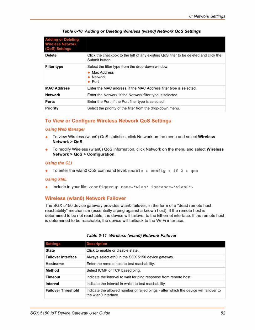
6: Network Settings
Table 6-10 Adding or Deleting Wireless (wlan0) Network QoS Settings
To View or Configure Wireless Network QoS Settings
Using Web Manager
To view Wireless (wlan0) QoS statistics, click Network on the menu and select Wireless Network > QoS.
To modify Wireless (wlan0) QoS information, click Network on the menu and select Wireless Network > QoS > Configuration.
Using the CLI
To enter the wlan0 QoS command level: enable > config > if 2 > qos
Using XML
Include in your file: <configgroup name="wlan" instance="wlan0">
Wireless (wlan0) Network FailoverThe SGX 5150 device gateway provides wlan0 failover, in the form of a "dead remote host reachability" mechanism (essentially a ping against a known host). If the remote host is determined to be not reachable, the device will failover to the Ethernet interface. If the remote host is determined to be reachable, the device will failback to the Wi-Fi interface.
Table 6-11 Wireless (wlan0) Network Failover
Adding or Deleting Wireless Network (QoS) Settings
Description
Delete Click the checkbox to the left of any existing QoS filter to be deleted and click the Submit button.
Filter type Select the filter type from the drop-down window:
Mac Address Network Port
MAC Address Enter the MAC address, if the MAC Address filter type is selected.
Network Enter the Network, if the Network filter type is selected.
Ports Enter the Port, if the Port filter type is selected.
Priority Select the priority of the filter from the drop-down menu.
Settings Description
State Click to enable or disable state.
Failover Interface Always select eth0 in the SGX 5150 device gateway.
Hostname Enter the remote host to test reachability.
Method Select ICMP or TCP based ping.
Timeout Indicate the interval to wait for ping response from remote host.
Interval Indicate the interval in which to test reachability
Failover Threshold Indicate the allowed number of failed pings - after which the device will failover to the wlan0 interface.
SGX 5150 IoT Device Gateway User Guide 52

6: Network Settings
To View or Configure Wireless Network Failover Settings
Using Web Manager
To view wireless network Failover statistics, click Network on the menu and select Wireless Network > Failover.
To modify wireless network Failover settings, click Network on the menu and select Wireless Network > Failover > Configuration.
Using the CLI
To enter the wlan0 link command level: enable > config > if 2 > failover
Using XML
Include in your file: <configgroup name="network failover" instance="wlan0">
Wired (usb0) Network
The wired (usb0) network pages are described in this section.
Interface (usb0) Status and ConfigurationTable 6-12 displays the wired (usb0) interface status and configuration information. The view-only status information is available on the Wired (usb0) Network Interface Status page. This same information is configurable on the Wired (usb0) Network Interface Configuration page.
Table 6-12 Wired (usb0) Network Interface
Failback Threshold Indicate the number of successful pings - after which the device will failback to the Ethernet interface.
Field/Button Description
State Select to enable or disable the interface
Hostname Enter the hostname for the interface. It must begin with a letter or number, continue with a sequence of letters, numbers, or hyphens, and end with a letter or number.
This setting will take effect immediately, but will not register the hostname with a DNS server until the next reboot.
Priority Priority ranges from 0-10. The IP stack will give the interface with the lowest numerical value highest priority and the highest numerical values lowest priority when sending data. This setting only applies when the device is not in bridging mode and both interfaces are connected to the same IP subnet.
MTU When DHCP is enabled, the MTU size is (usually) provided with the IP address. When not provided by the DHCP server, or using a static configuration, this value is used. The MTU size can be from 576 to 1500 bytes, the default being 1500 bytes.
IPv4 State Select to enable or disable.
Settings Description
SGX 5150 IoT Device Gateway User Guide 53

6: Network Settings
DHCP Client Select to turn On or Off. At boot up, after the physical link is up, the SGX 5150 unit will attempt to obtain IPv4 settings from a DHCP server and will periodically renew these settings with the server.
Note: Overrides the BOOTP client, the configured IPv4 address/mask, gateway, hostname, and domain. Changing this value requires you to reboot the device. Within Web Manager, click Renew to renew the DHCP lease.
IP Address Enter the static IPv4 address to use for the interface. You may enter it alone or in CIDR format.
Note: This setting will be used if Static IP is active (both DHCP and BOOTP are Disabled). Changing this value requires you to reboot the device. When DHCP or BOOTP is enabled, the SGX 5150 unit tries to obtain an IPv4 address from a DHCP or BOOTP server. If it cannot, the SGX 5150 unit generates and uses an Auto IP address in the range of 169.254.xxx.xxx, with a network mask of 255.255.0.0.
Default Gateway Enter the IPv4 address of the router for this network.
Note: This setting will be used if Static IP is active (both DHCP and BOOTP are Disabled).
Domain Enter the domain name suffix for the interface.
Note: This setting will be used when either static IP or auto IP is active, or if DHCP/BOOTP is active and no domain suffix was acquired from the server.
DHCP Client ID Enter the ID if the DHCP server requires a DHCP client ID option. The DHCP server’s lease table shows IP addresses and MAC addresses for devices. The lease table shows the client ID, in hexadecimal notation, instead of the SGX 5150 MAC address.
Primary DNS Enter the IP address of the primary domain name server (DNS.)
Note: This setting will be used when either Static IP or Auto IP is active, or if DHCP/BOOTP is active and no DNS server was acquired from the server.
Secondary DNS Enter the IP address of the secondary domain name server.
Note: This setting will be used when either Static IP or Auto IP is active, or if DHCP/BOOTP is active and no DNS server was acquired from the server.
IPv6 State Select to enable or disable.
IPv6 DHCP Client Select to turn On or Off. At bootup, after the physical link is up, the SGX 5150 unit will attempt to obtain IPv6 settings from a DHCPv6 server and will periodically renew these settings with the server.
On: enables the SGX 5150 server to obtain IPv6 setting from a DHCPv6 server upon bootup.
Off: enables the SGX 5150 server to obtain IPv4 settings from a DHCP server upon bootup.
Note: Overrides the configured IP address/mask, gateway, hostname, and domain. Changing this value requires you to reboot the device. Within Web Manager, click Renew to renew the DHCPV6 lease.
IPv6 Auto Configuration
Select to turn On or Off IPv6 auto configuration.
IPv6 IP Address Enter the static IPv6 address to use for the interface.
Note: This setting is used if Static IPv6 is active (DHCPv6 is Disabled). Changing this value requires a reboot. When DHCPv6 is enabled, the SGX 5150 unit tries to obtain an IPv6 address from a DHCPv6 server. If it cannot, then SGX 5150 unit generates and uses a Link local IPv6 address.
Field/Button Description
SGX 5150 IoT Device Gateway User Guide 54
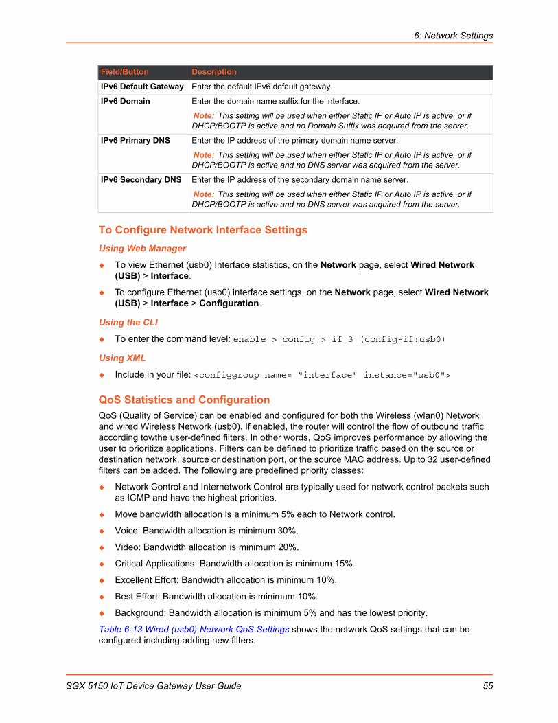
6: Network Settings
To Configure Network Interface Settings
Using Web Manager
To view Ethernet (usb0) Interface statistics, on the Network page, select Wired Network (USB) > Interface.
To configure Ethernet (usb0) interface settings, on the Network page, select Wired Network (USB) > Interface > Configuration.
Using the CLI
To enter the command level: enable > config > if 3 (config-if:usb0)
Using XML
Include in your file: <configgroup name= “interface" instance="usb0">
QoS Statistics and ConfigurationQoS (Quality of Service) can be enabled and configured for both the Wireless (wlan0) Network and wired Wireless Network (usb0). If enabled, the router will control the flow of outbound traffic according towthe user-defined filters. In other words, QoS improves performance by allowing the user to prioritize applications. Filters can be defined to prioritize traffic based on the source or destination network, source or destination port, or the source MAC address. Up to 32 user-defined filters can be added. The following are predefined priority classes:
Network Control and Internetwork Control are typically used for network control packets such as ICMP and have the highest priorities.
Move bandwidth allocation is a minimum 5% each to Network control.
Voice: Bandwidth allocation is minimum 30%.
Video: Bandwidth allocation is minimum 20%.
Critical Applications: Bandwidth allocation is minimum 15%.
Excellent Effort: Bandwidth allocation is minimum 10%.
Best Effort: Bandwidth allocation is minimum 10%.
Background: Bandwidth allocation is minimum 5% and has the lowest priority.
Table 6-13 Wired (usb0) Network QoS Settings shows the network QoS settings that can be configured including adding new filters.
IPv6 Default Gateway Enter the default IPv6 default gateway.
IPv6 Domain Enter the domain name suffix for the interface.
Note: This setting will be used when either Static IP or Auto IP is active, or if DHCP/BOOTP is active and no Domain Suffix was acquired from the server.
IPv6 Primary DNS Enter the IP address of the primary domain name server.
Note: This setting will be used when either Static IP or Auto IP is active, or if DHCP/BOOTP is active and no DNS server was acquired from the server.
IPv6 Secondary DNS Enter the IP address of the secondary domain name server.
Note: This setting will be used when either Static IP or Auto IP is active, or if DHCP/BOOTP is active and no DNS server was acquired from the server.
Field/Button Description
SGX 5150 IoT Device Gateway User Guide 55

6: Network Settings
Table 6-13 Wired (usb0) Network QoS Settings
To View and Configure Wired Network (USB) QoS Settings
Using Web Manager
To view Ethernet (usb0) QoS statistics, click Network on the menu and select Wired Network (USB) > QoS.
To modify Ethernet (usb0) QoS information, click Network on the menu and select Wired Network (USB) > QoS > Configuration.
Using the CLI
To enter the usb0 QoS command level: enable > config > if 3 > qos
Using XML
Include in your file: <configgroup name="ethernet" instance="usb0">
Wired (usb0) Network FailoverThe SGX 5150 device gateway provides a USB network failover, in the form of a "dead remote host reachability" mechanism (essentially a ping against a known host). If the remote host is determined to be not reachable, the device will failover to the Wi-Fi interface. If the remote host is determined to be reachable, the device will failback to the USB interface.
Table 6-14 Wired (usb0) Network Failover Settings
Wired (usb0) Network Settings
Description
State Click to enable or disable state.
Import filters Click to enable or disable import filters to import configurations from other interfaces.
Uplink Speed Enter the maximum uplink speed. Set 0 to set speed to default.
Delete Click the checkbox to the left of any existing QoS filter to be deleted and click the Submit button.
Filter type Select the filter type from the drop-down window:
Network Port
Network Enter the Network, if the Network filter type is selected.
Ports Enter the Port, if the Port filter type is selected.
Priority Select the priority of the filter from the drop-down menu.
Wired (usb0) Network (Failover) Settings
Description
State Click to enable or disable state.
Failover Interface Always select eth0 in the SGX 5150 device gateway.
Hostname Enter the remote host to test reachability.
Method Select ICMP or TCP based ping.
Timeout Indicate the interval to wait for ping response from remote host.
SGX 5150 IoT Device Gateway User Guide 56

6: Network Settings
To View and Configure Wired (USB0) Network Failover Settings
Using Web Manager
To view USB Failover statistics, click Network on the menu and select Wired Network (USB) > Failover.
To modify USB Failover settings, click Network on the menu and select Wired Network (USB) > Failover > Configuration.
Using the CLI
To enter the usb0 link command level: enable > config > if 3 > failover
Using XML
Include in your file: <configgroup name="network failover" instance="usb0">
Protocol Stack
There are various low level network stack specific items that are available for configuration. This includes settings related to IP, ICMP, and ARP, which are described in the sections below.
IP Settings This page contains lower level IP Network Stack specific configuration items.
Table 6-15 IP Protocol Stack Settings
Interval Indicate the interval in which to test reachability
Failover Threshold Indicate the allowed number of failed pings – after which the device will failover to the wlan0 interface.
Failback Threshold Indicate the number of successful pings – after which the device will failback to the Ethernet interface.
Protocol Stack IP Settings Description
IP Time to Live Enter the number of hops to be transmitted before the packet is discarded.
This value typically fills the time to live in the IP header. SNMP refers to this value as "ipDefaultTTL".
Multicast Time to Live This value fills the Time To Live in any multicast IP header. Normally this value will be one so the packet will be blocked at the first router. It is the number of hops allowed before a multicast packet is discarded. Enter the value to be greater than one to intentionally propagate multicast packets to additional routers.
Wired (usb0) Network (Failover) Settings
Description
SGX 5150 IoT Device Gateway User Guide 57

6: Network Settings
To Configure IP Protocol Stack Settings
Using Web Manager
To configure IP protocol settings, on the Network page, click Protocol Stack > IP.
Using the CLI
To enter the command level: enable > config > ip
Using XML
Include in your file: <configgroup name=”ip”>
ICMP Settings This page contains lower level ICMP Network Stack specific configuration items.
Table 6-16 ICMP Protocol Stack Settings
To Configure ICMP Protocol Stack Settings
Using Web Manager
To configure ICMP protocol settings, on the Network page, click Protocol Stack > ICMP.
Using the CLI
To enter the command level: enable > config > icmp
Using XML
Include in your file: <configgroup name=”icmp”>
ARP SettingsThis page contains lower level ARP network stack specific configuration items.The ARP cache can be manipulated manually by adding new entries and deleting existing ones. Added entries are static and for test purposes only.
Table 6-17 ARP Protocol Stack Settings
Protocol Stack ICMIP Settings
Description
State The State selection is used to turn on/off processing of ICMP messages. This includes both incoming and outgoing messages. Choose Enabled or Disabled.
Protocol Stack ARP Settings
Description
IP Address Enter the IP address to add the ARP cache.
MAC Address Enter the MAC address to add to the ARP cache.
Interface Select the type of interface if adding to the ARP cache.
Add (button) Click this button to add a new entry (after entering the IP address, MAC address and Interface info for the new entry above.)
SGX 5150 IoT Device Gateway User Guide 58
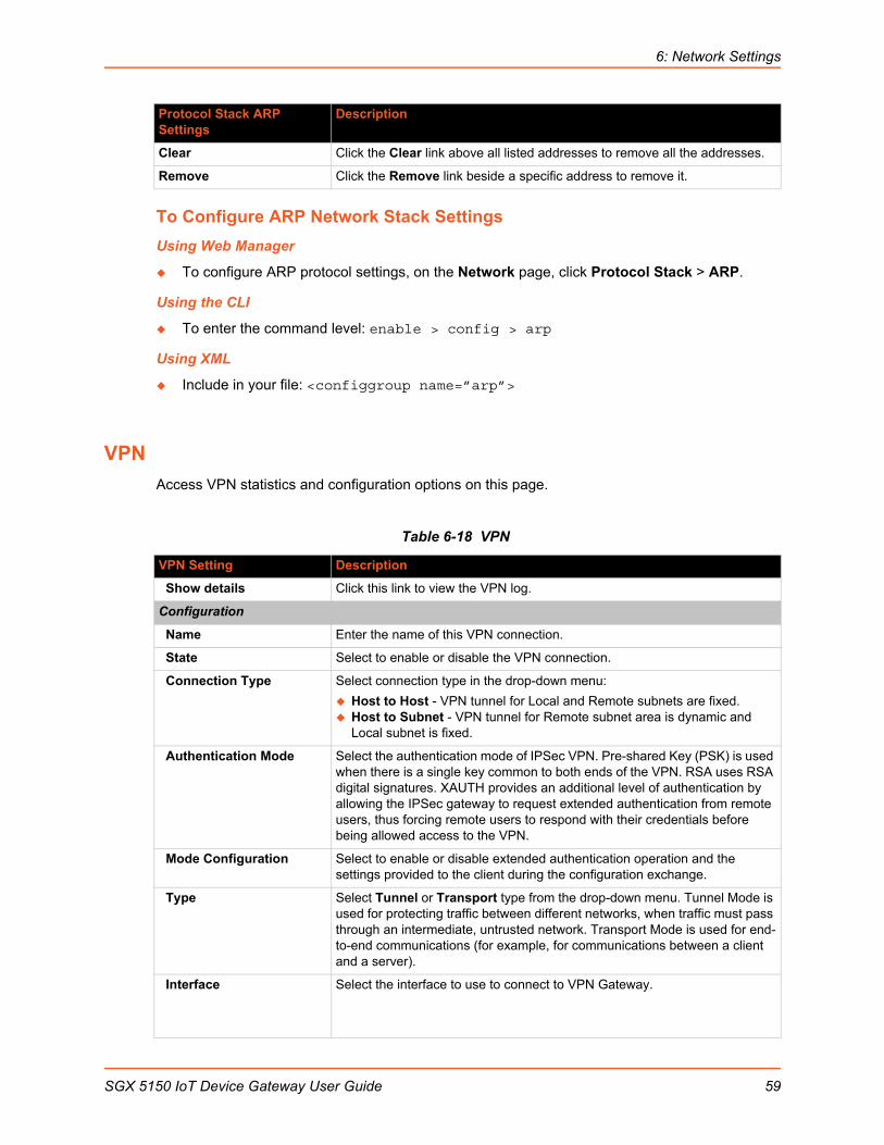
6: Network Settings
To Configure ARP Network Stack Settings
Using Web Manager
To configure ARP protocol settings, on the Network page, click Protocol Stack > ARP.
Using the CLI
To enter the command level: enable > config > arp
Using XML
Include in your file: <configgroup name=”arp”>
VPN
Access VPN statistics and configuration options on this page.
Table 6-18 VPN
Clear Click the Clear link above all listed addresses to remove all the addresses.
Remove Click the Remove link beside a specific address to remove it.
VPN Setting Description
Show details Click this link to view the VPN log.
Configuration
Name Enter the name of this VPN connection.
State Select to enable or disable the VPN connection.
Connection Type Select connection type in the drop-down menu:
Host to Host - VPN tunnel for Local and Remote subnets are fixed. Host to Subnet - VPN tunnel for Remote subnet area is dynamic and
Local subnet is fixed.
Authentication Mode Select the authentication mode of IPSec VPN. Pre-shared Key (PSK) is used when there is a single key common to both ends of the VPN. RSA uses RSA digital signatures. XAUTH provides an additional level of authentication by allowing the IPSec gateway to request extended authentication from remote users, thus forcing remote users to respond with their credentials before being allowed access to the VPN.
Mode Configuration Select to enable or disable extended authentication operation and the settings provided to the client during the configuration exchange.
Type Select Tunnel or Transport type from the drop-down menu. Tunnel Mode is used for protecting traffic between different networks, when traffic must pass through an intermediate, untrusted network. Transport Mode is used for end-to-end communications (for example, for communications between a client and a server).
Interface Select the interface to use to connect to VPN Gateway.
Protocol Stack ARP Settings
Description
SGX 5150 IoT Device Gateway User Guide 59
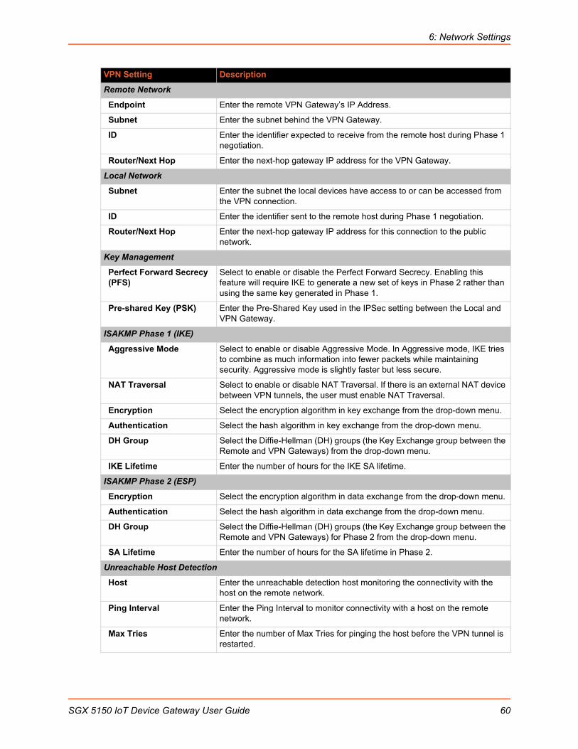
6: Network Settings
Remote Network
Endpoint Enter the remote VPN Gateway’s IP Address.
Subnet Enter the subnet behind the VPN Gateway.
ID Enter the identifier expected to receive from the remote host during Phase 1 negotiation.
Router/Next Hop Enter the next-hop gateway IP address for the VPN Gateway.
Local Network
Subnet Enter the subnet the local devices have access to or can be accessed from the VPN connection.
ID Enter the identifier sent to the remote host during Phase 1 negotiation.
Router/Next Hop Enter the next-hop gateway IP address for this connection to the public network.
Key Management
Perfect Forward Secrecy (PFS)
Select to enable or disable the Perfect Forward Secrecy. Enabling this feature will require IKE to generate a new set of keys in Phase 2 rather than using the same key generated in Phase 1.
Pre-shared Key (PSK) Enter the Pre-Shared Key used in the IPSec setting between the Local and VPN Gateway.
ISAKMP Phase 1 (IKE)
Aggressive Mode Select to enable or disable Aggressive Mode. In Aggressive mode, IKE tries to combine as much information into fewer packets while maintaining security. Aggressive mode is slightly faster but less secure.
NAT Traversal Select to enable or disable NAT Traversal. If there is an external NAT device between VPN tunnels, the user must enable NAT Traversal.
Encryption Select the encryption algorithm in key exchange from the drop-down menu.
Authentication Select the hash algorithm in key exchange from the drop-down menu.
DH Group Select the Diffie-Hellman (DH) groups (the Key Exchange group between the Remote and VPN Gateways) from the drop-down menu.
IKE Lifetime Enter the number of hours for the IKE SA lifetime.
ISAKMP Phase 2 (ESP)
Encryption Select the encryption algorithm in data exchange from the drop-down menu.
Authentication Select the hash algorithm in data exchange from the drop-down menu.
DH Group Select the Diffie-Hellman (DH) groups (the Key Exchange group between the Remote and VPN Gateways) for Phase 2 from the drop-down menu.
SA Lifetime Enter the number of hours for the SA lifetime in Phase 2.
Unreachable Host Detection
Host Enter the unreachable detection host monitoring the connectivity with the host on the remote network.
Ping Interval Enter the Ping Interval to monitor connectivity with a host on the remote network.
Max Tries Enter the number of Max Tries for pinging the host before the VPN tunnel is restarted.
VPN Setting Description
SGX 5150 IoT Device Gateway User Guide 60

6: Network Settings
Configuring VPN SettingsYou may edit or view VPN settings.
Using Web Manager
To view or configure VPN settings on the Network page, click VPN.
Using the CLI
To enter the VPN level: enable > configure > vpn1
Using XML
Include in your file: <configgroup name="vpn" instance="1">
Wi-Fi Protected Setup
Using Wi-Fi® protected setup (WPS), you have the option of connecting the SGX 5150 unit to a router or access point in a single operation instead of manually creating a profile with a network name (SSID), setting up wireless security parameters and updating the choice list. You may setup WPS through pin or push button functionality through Web Manager or through CLI.
Note: Not all access points support Wi-Fi protected setup pin or Wi-Fi protected setup push button.
Table 6-19 Wi-Fi Protected Setup
To Initiate WPS
Using Web Manager
To initiate WPS, on the Network page, click Wi-Fi Protected Setup.
Using the CLI
To enter the command level: enable > config > if 2 > link
Using XML
Not applicable.
WPS buttons Description
WPS (PIN) Click the WPS (PIN) button in Web Manager to setup WPS by pin and click OK in the confirmation popup which appears. A randomly generated pin will appear on the screen. Enter this pin at the access point and point your browser to the correct IP address.
WPS (PBC) Click the WPS (PBC) button in Web Manager to setup WPS by push button, click OK in the confirmation popup which appears, and the credentials are passed to the SGX 5150 unit automatically. Then point your browser to the correct IP address.
Note: Make sure the WPS PBC is triggered on the Access Point to utilize this option.
SGX 5150 IoT Device Gateway User Guide 61
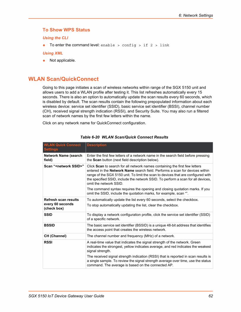
6: Network Settings
To Show WPS Status
Using the CLI
To enter the command level: enable > config > if 2 > link
Using XML
Not applicable.
WLAN Scan/QuickConnect
Going to this page initiates a scan of wireless networks within range of the SGX 5150 unit and allows users to add a WLAN profile after testing it. This list refreshes automatically every 15 seconds. There is also an option to automatically update the scan results every 60 seconds, which is disabled by default. The scan results contain the following prepopulated information about each wireless device: service set identifier (SSID), basic service set identifier (BSSI), channel number (CH), received signal strength indication (RSSI), and Security Suite. You may also run a filtered scan of network names by the first few letters within the name.
Click on any network name for QuickConnect configuration.
Table 6-20 WLAN Scan/Quick Connect Results
WLAN Quick Connect Settings
Description
Network Name (search field)
Enter the first few letters of a network name in the search field before pressing the Scan button (next field description below).
Scan “<network SSID>” Click Scan to search for all network names containing the first few letters entered in the Network Name search field. Performs a scan for devices within range of the SGX 5150 unit. To limit the scan to devices that are configured with the specified SSID, include the network SSID. To perform a scan for all devices, omit the network SSID.
The command syntax requires the opening and closing quotation marks. If you omit the SSID, include the quotation marks, for example, scan “”.
Refresh scan results every 60 seconds (check box)
To automatically update the list every 60 seconds, select the checkbox.
To stop automatically updating the list, clear the checkbox.
SSID To display a network configuration profile, click the service set identifier (SSID) of a specific network.
BSSID The basic service set identifier (BSSID) is a unique 48-bit address that identifies the access point that creates the wireless network.
CH (Channel) The channel number and frequency (MHz) of a network.
RSSI A real-time value that indicates the signal strength of the network. Green indicates the strongest, yellow indicates average, and red indicates the weakest signal strength.
The received signal strength indication (RSSI) that is reported in scan results is a single sample. To review the signal strength average over time, use the status command. The average is based on the connected AP.
SGX 5150 IoT Device Gateway User Guide 62

6: Network Settings
To View WLAN Link Scan and Status Information
Using Web Manager
To view the WLAN Link Scan and Status information, on the Network page, click WLAN Scan/Quick Connect.
Using the CLI
Not applicable.
Using XML
Include in your file: <statusggroup name=”wlan scan”>
WLAN Profiles
A WLAN profile defines all of the settings needed to establish a wireless connection. This is true when in infrastructure mode for an access point. A maximum of eight profiles can exist on the SGX 5150 unit at a time. All enabled profiles are active.
The SGX 5150 unit supports dynamic profiles and prioritization of the profiles. Dynamic Profiles are created using WPS or Quick Connect. Profiles are assigned numbers based on priority. For example, dynamic profiles list in reverse order of creation, followed by choice-list profiles, then any remaining profiles.
Table 6-21 WLAN Profiles
Configuring WLAN Profile SettingsYou can edit, create, or delete a WLAN profile.
Using Web Manager
To edit, create or delete a WLAN profile, on the Network page, click WLAN Profiles.
Security Suite The security suite of a network. For example: WEP, WPA, WPA2, WPS.
Although WPS is reported with the security flags, it does not indicate a security setting. WPS indicates that an AP supports WPS.
WLAN Profile Settings Description
Enabled (check box) Check the checkbox to the right of the WLAN profile listed right to enable the specific profile. Unchecking the enabled checkbox disables the WLAN profile.
Delete (check box) Check the checkbox to the right of the WLAN profile listed right and click the Submit button which appears, to delete the specific profile.
Name (link to WLAN profile)
Click an existing WLAN profile listed under the Name column to reveal the configuration options as shown in Table 6-22 Individual WLAN Profile Settings. Modify configuration options as desired.
Name (“Add a new profile” field)
Enter the name of a new profile and click Submit to add it. The profile appears in the WLAN Profiles list.
WLAN Quick Connect Settings (continued)
Description
SGX 5150 IoT Device Gateway User Guide 63
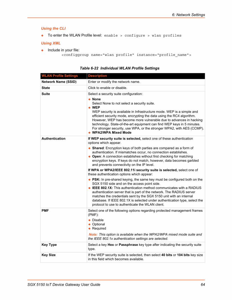
6: Network Settings
Using the CLI
To enter the WLAN Profile level: enable > configure > wlan profiles
Using XML
Include in your file: <configgroup name="wlan profile" instance="profile_name">
Table 6-22 Individual WLAN Profile Settings
WLAN Profile Settings Description
Network Name (SSID) Enter or modify the network name.
State Click to enable or disable.
Suite Select a security suite configuration:
NoneSelect None to not select a security suite.
WEPWEP security is available in Infrastructure mode. WEP is a simple and efficient security mode, encrypting the data using the RC4 algorithm. However, WEP has become more vulnerable due to advances in hacking technology. State-of-the-art equipment can find WEP keys in 5 minutes. For stronger security, use WPA, or the stronger WPA2, with AES (CCMP).
WPA2/WPA Mixed Mode
Authentication If WEP security suite is selected, select one of these authentication options which appear.
Shared: Encryption keys of both parties are compared as a form of authentication. If mismatches occur, no connection establishes.
Open: A connection establishes without first checking for matching encryption keys. If keys do not match, however, data becomes garbled and prevents connectivity on the IP level.
If WPA or WPA2/IEEE 802.11i security suite is selected, select one of these authentication options which appear:
PSK: In pre-shared keying, the same key must be configured both on the SGX 5150 side and on the access point side.
IEEE 802.1X: This authentication method communicates with a RADIUS authentication server that is part of the network. The RADIUS server matches the credentials sent by the SGX 5150 unit with an internal database. If IEEE 802.1X is selected under authentication type, select the protocol to use to authenticate the WLAN client.
PMF Select one of the following options regarding protected management frames (PMF):
Disable Optional Required
Note: This option is available when the WPA2/WPA mixed mode suite and the IEEE 802.1x authentication settings are selected.
Key Type Select a key Hex or Passphrase key type after indicating the security suite type.
Key Size If the WEP security suite is selected, then select 40 bits or 104 bits key size in this field which becomes available.
SGX 5150 IoT Device Gateway User Guide 64
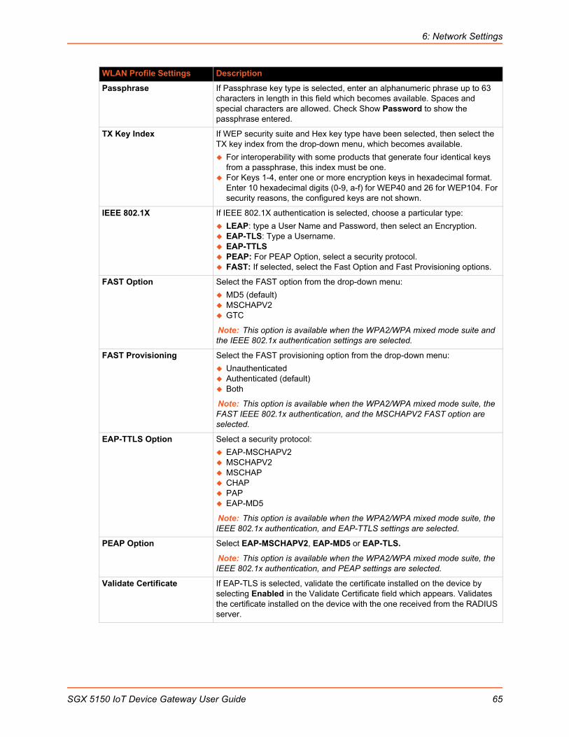
6: Network Settings
Passphrase If Passphrase key type is selected, enter an alphanumeric phrase up to 63 characters in length in this field which becomes available. Spaces and special characters are allowed. Check Show Password to show the passphrase entered.
TX Key Index If WEP security suite and Hex key type have been selected, then select the TX key index from the drop-down menu, which becomes available.
For interoperability with some products that generate four identical keys from a passphrase, this index must be one.
For Keys 1-4, enter one or more encryption keys in hexadecimal format. Enter 10 hexadecimal digits (0-9, a-f) for WEP40 and 26 for WEP104. For security reasons, the configured keys are not shown.
IEEE 802.1X If IEEE 802.1X authentication is selected, choose a particular type:
LEAP: type a User Name and Password, then select an Encryption. EAP-TLS: Type a Username. EAP-TTLS PEAP: For PEAP Option, select a security protocol. FAST: If selected, select the Fast Option and Fast Provisioning options.
FAST Option Select the FAST option from the drop-down menu:
MD5 (default) MSCHAPV2 GTC
Note: This option is available when the WPA2/WPA mixed mode suite and the IEEE 802.1x authentication settings are selected.
FAST Provisioning Select the FAST provisioning option from the drop-down menu:
Unauthenticated Authenticated (default) Both
Note: This option is available when the WPA2/WPA mixed mode suite, the FAST IEEE 802.1x authentication, and the MSCHAPV2 FAST option are selected.
EAP-TTLS Option Select a security protocol:
EAP-MSCHAPV2 MSCHAPV2 MSCHAP CHAP PAP EAP-MD5
Note: This option is available when the WPA2/WPA mixed mode suite, the IEEE 802.1x authentication, and EAP-TTLS settings are selected.
PEAP Option Select EAP-MSCHAPV2, EAP-MD5 or EAP-TLS.
Note: This option is available when the WPA2/WPA mixed mode suite, the IEEE 802.1x authentication, and PEAP settings are selected.
Validate Certificate If EAP-TLS is selected, validate the certificate installed on the device by selecting Enabled in the Validate Certificate field which appears. Validates the certificate installed on the device with the one received from the RADIUS server.
WLAN Profile Settings Description
SGX 5150 IoT Device Gateway User Guide 65
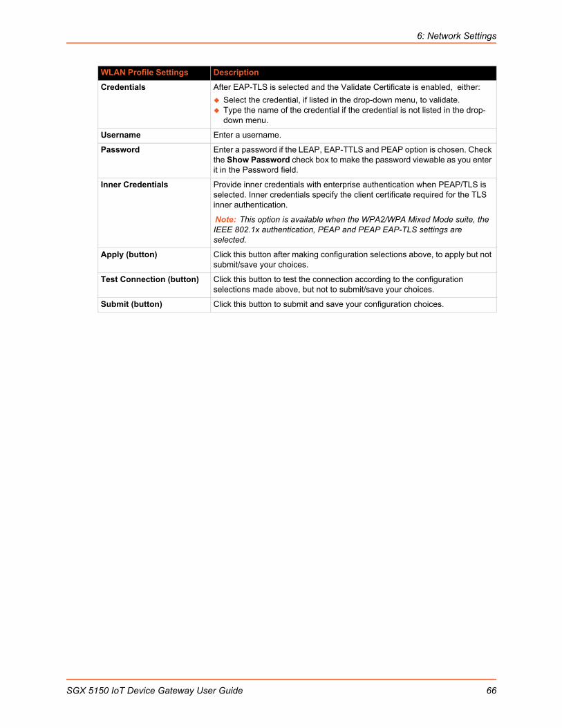
6: Network Settings
Credentials After EAP-TLS is selected and the Validate Certificate is enabled, either:
Select the credential, if listed in the drop-down menu, to validate. Type the name of the credential if the credential is not listed in the drop-
down menu.
Username Enter a username.
Password Enter a password if the LEAP, EAP-TTLS and PEAP option is chosen. Check the Show Password check box to make the password viewable as you enter it in the Password field.
Inner Credentials Provide inner credentials with enterprise authentication when PEAP/TLS is selected. Inner credentials specify the client certificate required for the TLS inner authentication.
Note: This option is available when the WPA2/WPA Mixed Mode suite, the IEEE 802.1x authentication, PEAP and PEAP EAP-TLS settings are selected.
Apply (button) Click this button after making configuration selections above, to apply but not submit/save your choices.
Test Connection (button) Click this button to test the connection according to the configuration selections made above, but not to submit/save your choices.
Submit (button) Click this button to submit and save your configuration choices.
WLAN Profile Settings Description
SGX 5150 IoT Device Gateway User Guide 66
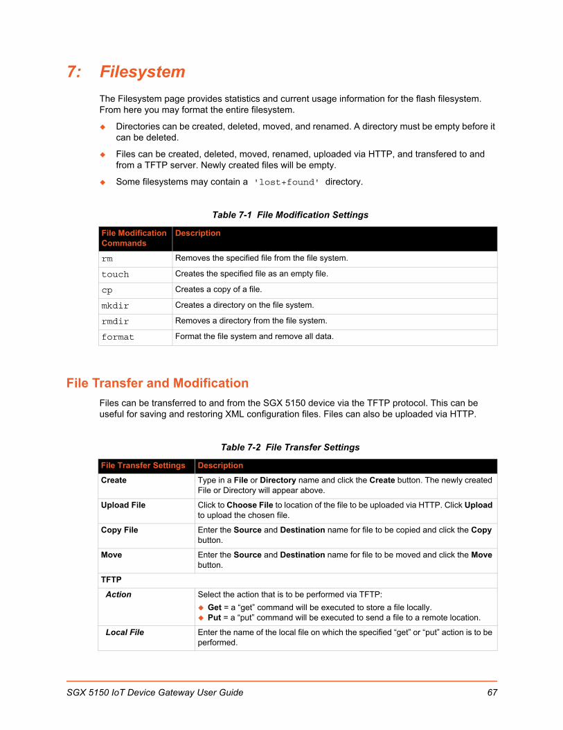
7: Filesystem
The Filesystem page provides statistics and current usage information for the flash filesystem. From here you may format the entire filesystem.
Directories can be created, deleted, moved, and renamed. A directory must be empty before it can be deleted.
Files can be created, deleted, moved, renamed, uploaded via HTTP, and transfered to and from a TFTP server. Newly created files will be empty.
Some filesystems may contain a 'lost+found' directory.
Table 7-1 File Modification Settings
File Transfer and Modification
Files can be transferred to and from the SGX 5150 device via the TFTP protocol. This can be useful for saving and restoring XML configuration files. Files can also be uploaded via HTTP.
Table 7-2 File Transfer Settings
File Modification Commands
Description
rm Removes the specified file from the file system.
touch Creates the specified file as an empty file.
cp Creates a copy of a file.
mkdir Creates a directory on the file system.
rmdir Removes a directory from the file system.
format Format the file system and remove all data.
File Transfer Settings Description
Create Type in a File or Directory name and click the Create button. The newly created File or Directory will appear above.
Upload File Click to Choose File to location of the file to be uploaded via HTTP. Click Upload to upload the chosen file.
Copy File Enter the Source and Destination name for file to be copied and click the Copy button.
Move Enter the Source and Destination name for file to be moved and click the Move button.
TFTP
Action Select the action that is to be performed via TFTP:
Get = a “get” command will be executed to store a file locally. Put = a “put” command will be executed to send a file to a remote location.
Local File Enter the name of the local file on which the specified “get” or “put” action is to be performed.
SGX 5150 IoT Device Gateway User Guide 67

7: Filesystem
To View, Transfer, or Modify Filesystem Files
Using Web Manager
To view current filesystem browser statistics or to format the filesystem, click Filesystem in the menu and select Statistics.
Note: Formatting the filesystem will cause existing files on the filesystem to be deleted.
To create a new file or directory, upload an existing file, copy or move a file, click Filesystem in the menu and select Browse.
Using the CLI
To enter the Filesystem command level: enable > filesystem
Using XML
Not applicable.
Remote File Enter the name of the file at the remote location that is to be stored locally (“get’) or externally (“put”).
Host Enter the IP address or name of the host involved in this operation.
Port Enter the number of the port involved in TFTP operations.
Transfer (button) Click the Transfer button after entering all TFTP settings.
File Transfer Settings Description
SGX 5150 IoT Device Gateway User Guide 68
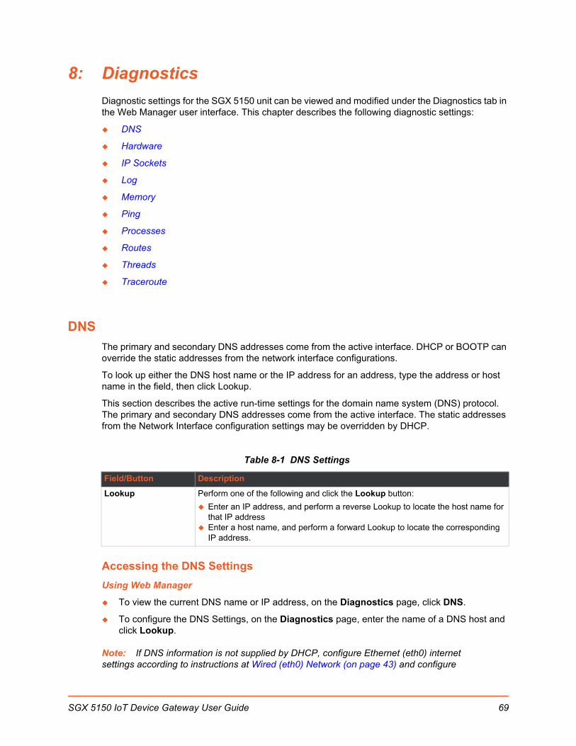
8: Diagnostics
Diagnostic settings for the SGX 5150 unit can be viewed and modified under the Diagnostics tab in the Web Manager user interface. This chapter describes the following diagnostic settings:
DNS
Hardware
IP Sockets
Log
Memory
Ping
Processes
Routes
Threads
Traceroute
DNS
The primary and secondary DNS addresses come from the active interface. DHCP or BOOTP can override the static addresses from the network interface configurations.
To look up either the DNS host name or the IP address for an address, type the address or host name in the field, then click Lookup.
This section describes the active run-time settings for the domain name system (DNS) protocol. The primary and secondary DNS addresses come from the active interface. The static addresses from the Network Interface configuration settings may be overridden by DHCP.
Table 8-1 DNS Settings
Accessing the DNS Settings
Using Web Manager
To view the current DNS name or IP address, on the Diagnostics page, click DNS.
To configure the DNS Settings, on the Diagnostics page, enter the name of a DNS host and click Lookup.
Note: If DNS information is not supplied by DHCP, configure Ethernet (eth0) internet settings according to instructions at Wired (eth0) Network (on page 43) and configure
Field/Button Description
Lookup Perform one of the following and click the Lookup button:
Enter an IP address, and perform a reverse Lookup to locate the host name for that IP address
Enter a host name, and perform a forward Lookup to locate the corresponding IP address.
SGX 5150 IoT Device Gateway User Guide 69
8: Diagnostics
Wireless (wlan0) Network interface settings according to instructions at Wireless (wlan0) Network (on page 48).
Using CLI
To enter CLI command level: enable > dns
Using XML
Not applicable.
Hardware
View the CPU type, CPU speed, RAM size and flash size of the hardware on this Web Manager page.
To View Hardware Information
Using Web Manager
To view hardware information, on the Diagnostics page, click Hardware.
Using the CLI
To enter the command level: enable > device, show hardware information
Using XML
Include in your file: <statusgroup name= ¨hardware¨>
IP Sockets
You can view the list of listening and connected IP sockets.
To View the List of IP Sockets
Using Web Manager
To view IP Sockets, on the Diagnostics page, click IP Sockets.
Using the CLI
To enter the command level: enable > show ip sockets
Using XML
Include in your file: <statusgroup name=”ip sockets”>
SGX 5150 IoT Device Gateway User Guide 70

8: Diagnostics
Log
Configure a line or disable the diagnostic log on this Web Manager page.
Table 8-2 Log Settings
To Configure the Diagnostic Log Output
Using Web Manager
To configure the Diagnostic Log output, on the Diagnostics page, click Log.
Using the CLI
To enter the command level: enable > config > diagnostics > log
Using XML
Include in your file: <configgroup name=”diagnostics”>
Memory
The memory information includes the total, used, and available memory (in kilobytes).
To View Memory Usage
Using Web Manager
To view memory information, on the Diagnostics page, click Memory.
Using the CLI
To enter the command level: enable > device, show memory
Using XML
Include in your file: <statusgroup name="memory">
Ping
You can use Ping to test connectivity to a remote host.
Table 8-3 Ping Configuration
Diagnostics Log Description
Output Select a diagnostic log output type:
Disable - Turn off the logging feature. Line 1 or Line 2 - Directs logging to the selected serial line. USB 1 - Directs logging to the usb port.
IP Socket Description
Host Enter the IP address or host name for the SGX 5150 unit that you want to ping.
SGX 5150 IoT Device Gateway User Guide 71
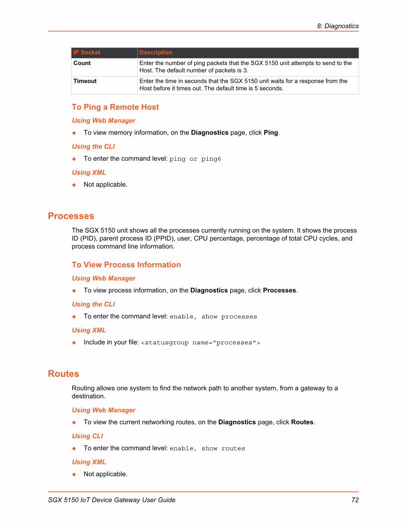
8: Diagnostics
To Ping a Remote Host
Using Web Manager
To view memory information, on the Diagnostics page, click Ping.
Using the CLI
To enter the command level: ping or ping6
Using XML
Not applicable.
Processes
The SGX 5150 unit shows all the processes currently running on the system. It shows the process ID (PID), parent process ID (PPID), user, CPU percentage, percentage of total CPU cycles, and process command line information.
To View Process Information
Using Web Manager
To view process information, on the Diagnostics page, click Processes.
Using the CLI
To enter the command level: enable, show processes
Using XML
Include in your file: <statusgroup name="processes">
Routes
Routing allows one system to find the network path to another system, from a gateway to a destination.
Using Web Manager
To view the current networking routes, on the Diagnostics page, click Routes.
Using CLI
To enter the command level: enable, show routes
Using XML
Not applicable.
Count Enter the number of ping packets that the SGX 5150 unit attempts to send to the Host. The default number of packets is 3.
Timeout Enter the time in seconds that the SGX 5150 unit waits for a response from the Host before it times out. The default time is 5 seconds.
IP Socket Description
SGX 5150 IoT Device Gateway User Guide 72

8: Diagnostics
Threads
The SGX 5150 unit threads information shows details of threads in the ltrx_evo task which can be useful for technical experts in debugging.
To View Thread Information
Using Web Manager
To view thread information, on the Diagnostics page, click Threads.
Using the CLI
To enter the command level: enable > auto show processes or show processes
Using XML
Not applicable.
Traceroute
You can use traceroute to trace a packet from the SGX 5150 unit to an Internet host. A traceroute shows how many hops the packet requires to reach the host, and how long each hop takes. This information can be helpful to diagnose delays for a web page that loads slowly.
Table 8-4 Traceroute Settings
To Perform a Traceroute
Using Web Manager
To view traceroute information, on the Diagnostics page, click Traceroute.
Using the CLI
To enter the command level: enable > trace route
Using XML
Not applicable.
Traceroute Fields Description
Host Enter the IP address or DNS host name of the destination device.
Protocol Select the protocol that you want to use for the traceroute.
SGX 5150 IoT Device Gateway User Guide 73
9: Administration
Administrative features for the SGX 5150 unit are organized beneath the Administration tab in the Web Manager user interface. This chapter describes the following administrative settings:
Actions
Applications
CLI
Clock
Discovery
FTP
Gateway
GRE
Host
HTTP
Line
USB
Modbus
SMTP
SNMP Settings
SSH
SSL
Syslog
System
Terminal
Tunnel
User Management
XML
Quick Setup
SGX 5150 IoT Device Gateway User Guide 74

9: Administration
Actions
Table 9-1 contains the configuration options for all the alarms and reports listed above.
Table 9-1 Action Settings
Action Settings Description
Delay Use Delay to defer alarm processing. Alarm actions will not be executed if the cause is corrected within this time.
Email Use Email to send an email to configured Email recipients. If an Alarm Email profile number is selected, that email will be sent when the
alarm is turned on. The contents of Alarm Message will be placed into the email body when an alarm email is sent. If the alarm stays on longer than the Reminder Interval, another alarm email is sent.
If a Normal Email profile number is selected, that email will be sent when the alarm is turned off. The contents of Normal Message will be placed into the email body when a normal email is sent. If the alarm stays off longer than the Reminder Interval, another normal email is sent.
FTP Put Use FTP Put to put a file on configured FTP server. Filename will be used to upload to remote FTP server. The IP Address or hostname is the FTP server to connect. Port number is port on which FTP server is listening on. Use Protocol to connect to FTP server. FTPS is a SSL encrypted communication channel and SSL Trusted Authorities must be setup with FTP server SSL certificate. Username is used to logon to FTP server. If FTP server does not require authentication, use anonymous. Password is used to logon to FTP server. If FTP server does not require authentication, a common practice is to use user’s email address. If the alarm stays on or off longer than the Reminder Interval, another FTP Put is performed. In Sequential Mode, connections will be attempted starting with number 1 until a connection is successful. In Simultaneous Mode, all possible connections will be made.
HTTP Post Use HTTP Post post to configured HTTP server.
The URL appears behind the HTTP server IP address or hostname. E.g. http://some_http_server/some_url The IP Address or hostname is the HTTP server to connect to. Port number is the port which HTTP server is listening on. Use Protocol to connect to HTTP server. HTTPS is a SSL encrypted communication channel and SSL Trusted Authorities must be setup with HTTP server SSL certificate. Username used to logon to HTTP server if authentication is required. Password used to logon to HTTP server if authentication is required. If the alarm stays on or off longer than the Reminder Interval, another HTTP Post is performed. In Sequential Mode, connections will be attempted starting with number 1 until a connection is successful. In Simultaneous Mode, all possible connections will be made.
SNMP Trap Use SNMP Trap to send SNMP trap to configured trap destinations. SNMP Trap State can be Enabled or Disabled. The contents of Alarm Message are included when an alarm SNMP trap is sent. If the alarm stays on longer than the Reminder Interval, another alarm SNMP Trap is sent. The contents of Normal Message are included when a normal SNMP trap is sent. If the alarm stays off longer than the Reminder Interval, another normal SNMP Trap is sent.
SGX 5150 IoT Device Gateway User Guide 75

9: Administration
To Configure Action Settings
Using Web Manager
To view Action status, on the Administration page, click Action > Status on the menu.
To modify Action information, on the Administration page, click Action > Configuration on the menu and select a specific action from the drop-down menu. SMTP (on page 98) lists the options.
Using the CLI
To enter the eth0 link state change command level: enable > config > action > eth0 link state change
To enter the wlan0 link state change command level: enable > config > action > wlan0 link state change
To enter device temperature change command level: enable > config > action > device temperature change
To enter on scheduled reboot command level: enable > config > action > on scheduled reboot
Using XML
Include in your file: <configgroup name = "action" instance = "eth0 link state change">
Include in your file: <configgroup name = "action" instance = "wlan0 link state change">
Include in your file: <configgroup name = "device temperature change"
Include in your file: <configgroup name = "action" instance = "on scheduled reboot">
PythonPython™ is a dynamic, object-oriented programming language that can be used for developing a wide range of software applications. The Lantronix SGX 5150 includes the installation of Python interpreter, making it easy to load and run custom Python scripts on your device.
The version of Python programming language installed on the Lantronix SGX 5150 comes with "batteries included" by having the Python language's standard library. In addition, the developer can take advantage of thousands of available third party packages to speed up development.
IDE
Python scripts can be written with any text editor. If using Windows for development, Notepad++ is a powerful choice as this text editor includes traditional IDE features such as syntax highlighting and automatic indentation (http://notepad-plus-plus.org/). Notepad++ also includes the ability to customize through plugins. Some interesting plugins for the development of Python scripts for the Lantronix SGX 5150 platform include the following:
PyNPP: https://github.com/mpcabd/PyNPPThis plugin allows the user to use keystrokes to launch the open Python script in the local Python interpreter for debugging and testing.
SGX 5150 IoT Device Gateway User Guide 76
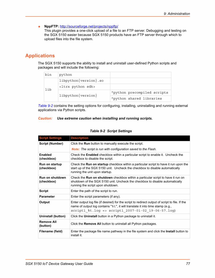
9: Administration
NppFTP: http://sourceforge.net/projects/nppftp/This plugin provides a one-click upload of a file to an FTP server. Debugging and testing on the SGX 5150 easier because SGX 5150 products have an FTP server through which to upload files into the file system.
Applications
The SGX 5150 supports the ability to install and uninstall user-defined Python scripts and packages and will include the following:
Table 9-2 contains the setting options for configuring, installing, uninstalling and running external applications via Python scripts.
Caution: Use extreme caution when installing and running scripts.
Table 9-2 Script Settings
bin python
lib
libpythonversion.so
<ltrx python sdk>
libpythonversion"python precompiled scripts
"python shared libraries
Script Settings Description
Script (Number) Click the Run button to manually execute the script.
Note: The script is run with configuration saved to the Flash.
Enabled (checkbox)
Check the Enabled checkbox within a particular script to enable it. Uncheck the checkbox to disable the script.
Run on startup (checkbox)
Check the Run on startup checkbox within a particular script to have it run upon the start up of the SGX 5150 unit. Uncheck the checkbox to disable automatically running the unit upon startup.
Run on shutdown (checkbox)
Check the Run on shutdown checkbox within a particular script to have it run on shutdown of the SGX 5150 unit. Uncheck the checkbox to disable automatically running the script upon shutdown.
Script Enter the path of the script to run.
Parameter Enter the script parameters (if any).
Output Enter output log file (if desired) for the script to redirect output of script to file. If the name of output log contains "%t", it will translate it into time stamp (e.g., script1_%t.log => script1_2007-01-02_19-06-57.log)
Uninstall (button) Click the Uninstall button in a Python package to uninstall it.
Remove All (button)
Click the Remove All button to uninstall all Python packages.
Filename (field) Enter the package file name pathway in the file system and click the Install button to install it.
SGX 5150 IoT Device Gateway User Guide 77

9: Administration
To Configure Application Settings
Using Web Manager
To configure application scripts, on the Administration page, click Applications on the menu.
Using the CLI
To enter the application script change command level: enable > config > applications
Using XML
Include in your file: <configgroup name = "applications">
CLI
The command line interface (CLI) settings allow you to control how users connect to and interact with the command line of the SGX 5150 unit. It is possible to configure access via the Telnet and SSH protocols, in addition to general CLI options.
CLI Status and ConfigurationView-only status information on the Command Line Interface Status page displays the current Telnet and SSH server status, uptime, and current connections (if any.)
See Table 9-3 for the bridge settings that can be modified on the Command Line Interface Configuration page.
Table 9-3 CLI Configuration Settings
Command Line Interface Configuration Settings
Description
Enable Level Password Enter the password for access to the Command Mode Enable level. There is no password by default.
Quit Connect Line Enter the Quit Connect Line string to be used to terminate a Telnet and SSH session and resume the CLI. Type <control> before the key to be pressed while holding down the [Ctrl] key (example: <control>L)
Inactivity Timeout Set a time period in which the CLI session should disconnect if no data is received. Enter 0 to disable. Blank the display field to restore the default.
Line Authentication Enable or Disable authentication for CLI access on the serial lines.
Telnet State Enable or Disable CLI access via Telnet
Telnet Port Enter an alternative Telnet Port to override the default used by the CLI server.
Blank the field to restore the default.
Telnet Max Sessions Specify the maximum number of concurrent Telnet sessions that will be allowed.
Telnet Authentication Enable or Disable authentication for Telnet logins.
SSH State Select to Enable or Disable CLI access via Telnet.
SGX 5150 IoT Device Gateway User Guide 78
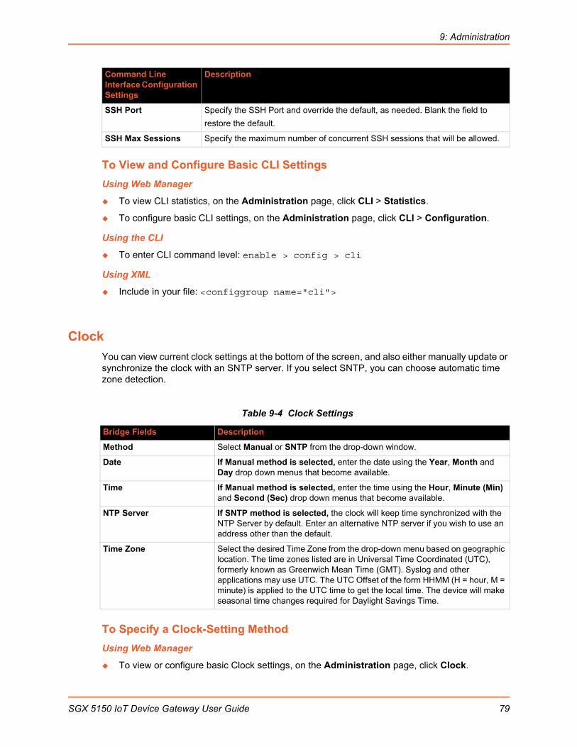
9: Administration
To View and Configure Basic CLI Settings
Using Web Manager
To view CLI statistics, on the Administration page, click CLI > Statistics.
To configure basic CLI settings, on the Administration page, click CLI > Configuration.
Using the CLI
To enter CLI command level: enable > config > cli
Using XML
Include in your file: <configgroup name="cli">
Clock
You can view current clock settings at the bottom of the screen, and also either manually update or synchronize the clock with an SNTP server. If you select SNTP, you can choose automatic time zone detection.
Table 9-4 Clock Settings
To Specify a Clock-Setting Method
Using Web Manager
To view or configure basic Clock settings, on the Administration page, click Clock.
SSH Port Specify the SSH Port and override the default, as needed. Blank the field to
restore the default.
SSH Max Sessions Specify the maximum number of concurrent SSH sessions that will be allowed.
Bridge Fields Description
Method Select Manual or SNTP from the drop-down window.
Date If Manual method is selected, enter the date using the Year, Month and Day drop down menus that become available.
Time If Manual method is selected, enter the time using the Hour, Minute (Min) and Second (Sec) drop down menus that become available.
NTP Server If SNTP method is selected, the clock will keep time synchronized with the NTP Server by default. Enter an alternative NTP server if you wish to use an address other than the default.
Time Zone Select the desired Time Zone from the drop-down menu based on geographic location. The time zones listed are in Universal Time Coordinated (UTC), formerly known as Greenwich Mean Time (GMT). Syslog and other applications may use UTC. The UTC Offset of the form HHMM (H = hour, M = minute) is applied to the UTC time to get the local time. The device will make seasonal time changes required for Daylight Savings Time.
Command Line Interface Configuration Settings
Description
SGX 5150 IoT Device Gateway User Guide 79

9: Administration
Using the CLI
To enter Clock command level: enable > config > clock
Using XML
Include in your file: <configgroup name="clock">
Discovery
Network discovery allows your computer to locate other computers and devices on the network. This setting also allows other computers to see your computer.
The current statistics and configuration options for device discovery, including UPnP query port, are available for the SGX 5150 unit.
Table 9-5 Discovery Settings
To Configure Discovery
Using Web Manager
To configure Discovery, on the Administration page, click Discovery.
Using the CLI
To enter Discovery command level: enable > config > discovery
Using XML
Include in your file: <configgroup name="discovery">
View and configure email alerts relating to events occurring within the system.
Table 9-6 Email Configuration
Discovery Settings Description
Query Port Server State Select to enable or disable the query port server from responding to autodiscovery messages on port 0x77FE.
UPnP Server State Select to enable or disable the UPnP server from discovering devices in Windows network places.
UPnP Server Port Update the UPnP server port. Leaving this field blank will restore the default settings.
Email – Configuration Settings
Description
From Click the Configure SMTP link to configure SMTP. See SMTP (on page 98).
To Enter the email address to which the email alerts will be sent. Multiple addresses are separated by semicolon (;). Required field if email is to be sent.
SGX 5150 IoT Device Gateway User Guide 80

9: Administration
To View, Configure and Send Email
Note: The following section describes the steps to view and configure Email 1 settings; these steps apply to other emails available for the device.
Using Web Manager
To view Email statistics, on the Administrations page, click Email > Statistics.
To configure basic Email settings and send an email, on the Administrations page, click Email > Configuration.
Using the CLI
To enter Email command level: enable > email 1
Using XML
Include in your file: <configgroup name=”email” instance=”1”>
FTP
The FTP protocol can be used to upload and download user files, and upgrade the SGX 5150 firmware. A configurable option is provided to enable or disable access via this protocol.
Table 9-7 FTP Settings
CC Enter the email address to which the email alerts will be copied. Multiple addresses are separated by semicolon (;).
Reply To Enter the email address to list in the Reply-To field of the email alert.
Subject Enter the subject for the email alert.
Note: Emails sent as a result of an alarm will display the name of the alarm in the subject of the email, overriding the email subject configured in this field.
Message File Enter the path of the file to send with the email alert. This file appears within the message body of the email, not as an attachment.
Priority Select the priority level for the email alert:
Urgent High Normal Low Very Low
FTP Settings Description
State Select to enable or disable the FTP server:
Enabled (default) Disabled
Email – Configuration Settings (continued)
Description
SGX 5150 IoT Device Gateway User Guide 81

9: Administration
To Configure FTP Settings
Using Web Manager
To configure FTP, on the Administration page, click FTP.
Using the CLI
To enter the FTP command level: enable > config > ftp
Using XML
Include in your file: <configgroup name="ftp server">
Gateway
The SGX 5150 IoT device gateway can be configured as a wireless router with DHCP server functionality.
StatusThis page displays the current configuration and statistics information for the gateway.
To view gateway status: on the Administration page, click Gateway > Status.
WAN
Table 9-8 WAN Configuration
Gateway Settings Description
Operating Mode Select the type of operating mode: Disabled: prevents the device to be used as a gateway; use the device
normally. Gateway: allows the device to be used as a router with NAT. Router: allows the device to be used as a router without NAT.
Firewall Select to enable or disable firewall: Enabled: enables the device firewall. Disabled: disable the device firewall.
MAC Address filter Select to enable or disable the MAC address filter.
Interface Specify the WAN interface; the wlan0 interface.
IP Address Assign a static IP address to the gateway.
IPv6 Address Assign a static IPv6 address to the gateway.
Primary DNS Enter the IP address of the primary Domain Name Server.
Note: This setting will be used when either Static IP or Auto IP is active, or if DHCP/BOOTP is active and no DNS server was acquired from the server.
Secondary DNS Enter the IP address of the secondary Domain Name Server.
Note: This setting will be used when either Static IP or Auto IP is active, or if DHCP/BOOTP is active and no DNS server was acquired from the server.
SGX 5150 IoT Device Gateway User Guide 82
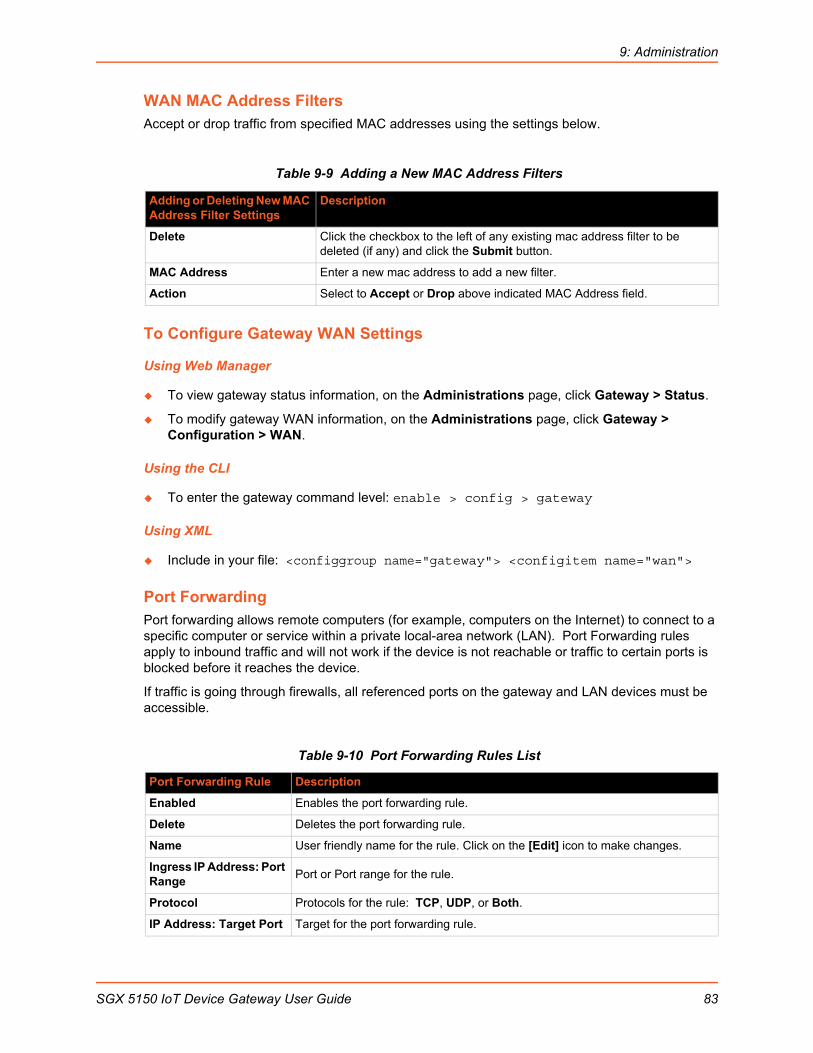
9: Administration
WAN MAC Address FiltersAccept or drop traffic from specified MAC addresses using the settings below.
Table 9-9 Adding a New MAC Address Filters
To Configure Gateway WAN Settings
Using Web Manager
To view gateway status information, on the Administrations page, click Gateway > Status.
To modify gateway WAN information, on the Administrations page, click Gateway > Configuration > WAN.
Using the CLI
To enter the gateway command level: enable > config > gateway
Using XML
Include in your file: <configgroup name="gateway"> <configitem name="wan">
Port ForwardingPort forwarding allows remote computers (for example, computers on the Internet) to connect to a specific computer or service within a private local-area network (LAN). Port Forwarding rules apply to inbound traffic and will not work if the device is not reachable or traffic to certain ports is blocked before it reaches the device.
If traffic is going through firewalls, all referenced ports on the gateway and LAN devices must be accessible.
Table 9-10 Port Forwarding Rules List
Adding or Deleting New MAC Address Filter Settings
Description
Delete Click the checkbox to the left of any existing mac address filter to be deleted (if any) and click the Submit button.
MAC Address Enter a new mac address to add a new filter.
Action Select to Accept or Drop above indicated MAC Address field.
Port Forwarding Rule Description
Enabled Enables the port forwarding rule.
Delete Deletes the port forwarding rule.
Name User friendly name for the rule. Click on the [Edit] icon to make changes.
Ingress IP Address: Port Range
Port or Port range for the rule.
Protocol Protocols for the rule: TCP, UDP, or Both.
IP Address: Target Port Target for the port forwarding rule.
SGX 5150 IoT Device Gateway User Guide 83
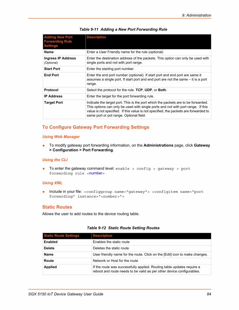
9: Administration
Table 9-11 Adding a New Port Forwarding Rule
To Configure Gateway Port Forwarding Settings
Using Web Manager
To modify gateway port forwarding information, on the Administrations page, click Gateway > Configuration > Port Forwarding.
Using the CLI
To enter the gateway command level: enable > config > gateway > port forwarding rule <number>
Using XML
Include in your file: <configgroup name="gateway"> <configitem name="port forwarding" instance="<number>">
Static RoutesAllows the user to add routes to the device routing table.
Table 9-12 Static Route Setting Routes
Adding New Port Forwarding Rule Settings
Description
Name Enter a User Friendly name for the rule (optional)
Ingress IP Address (Optional)
Enter the destination address of the packets. This option can only be used with single ports and not with port range.
Start Port Enter the starting port number.
End Port Enter the end port number (optional). If start port and end port are same it assumes a single port. If start port and end port are not the same – it is a port range.
Protocol Select the protocol for the rule. TCP, UDP, or Both.
IP Address Enter the target for the port forwarding rule.
Target Port Indicate the target port. This is the port which the packets are to be forwarded. This options can only be used with single ports and not with port range. If this value is not specified. If this value is not specified, the packets are forwarded to same port or pot range. Optional field.
Static Route Settings Description
Enabled Enables the static route
Delete Deletes the static route
Name User friendly name for the route. Click on the [Edit] icon to make changes.
Route Network or Host for the route
Applied If the route was successfully applied. Routing table updates require a reboot and route needs to be valid as per other device configurables.
SGX 5150 IoT Device Gateway User Guide 84
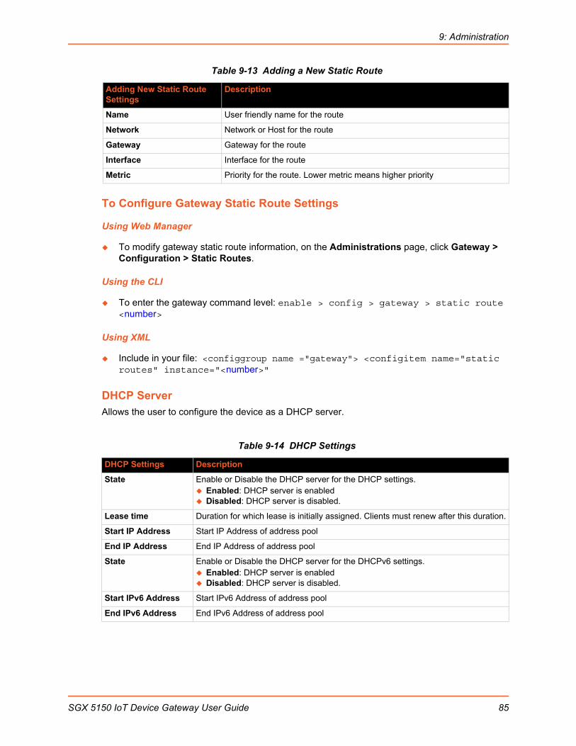
9: Administration
Table 9-13 Adding a New Static Route
To Configure Gateway Static Route Settings
Using Web Manager
To modify gateway static route information, on the Administrations page, click Gateway > Configuration > Static Routes.
Using the CLI
To enter the gateway command level: enable > config > gateway > static route <number>
Using XML
Include in your file: <configgroup name ="gateway"> <configitem name="static routes" instance="<number>"
DHCP ServerAllows the user to configure the device as a DHCP server.
Table 9-14 DHCP Settings
Adding New Static Route Settings
Description
Name User friendly name for the route
Network Network or Host for the route
Gateway Gateway for the route
Interface Interface for the route
Metric Priority for the route. Lower metric means higher priority
DHCP Settings Description
State Enable or Disable the DHCP server for the DHCP settings. Enabled: DHCP server is enabled Disabled: DHCP server is disabled.
Lease time Duration for which lease is initially assigned. Clients must renew after this duration.
Start IP Address Start IP Address of address pool
End IP Address End IP Address of address pool
State Enable or Disable the DHCP server for the DHCPv6 settings. Enabled: DHCP server is enabled Disabled: DHCP server is disabled.
Start IPv6 Address Start IPv6 Address of address pool
End IPv6 Address End IPv6 Address of address pool
SGX 5150 IoT Device Gateway User Guide 85

9: Administration
To Configure Gateway DHCP Server Settings
Using Web Manager
To modify gateway DHCP server or static lease information, on the Administrations page, click Gateway > Configuration > DHCP Server.
Using the CLI
To enter the gateway command level: enable > config > gateway > dhcp server
Using XML
Include in your file: <configgroup name = "dhcp server">
Static Lease ListingThe device also provides the ability to pre-assign specific IP addresses to connected devices using static leases. This would ensure that the connected device (identified by the MAC address) always gets the same IP address even while using DHCP.
Table 9-15 Static Lease Listing
Table 9-16 Add a Static Lease
Routing ProtocolsThe SGX 5150 IoT device gateway allows the configuration of routing protocols. Routing protocols specify how routers communicate with each other, disseminating information that enables the selection of routes between any two nodes on a computer network. Routing algorithms determine the specific choice of route. Each router has a prior knowledge of networks directly attached to it. A routing protocol shares this information among immediate neighbors first, then through the network. This way, routers gain knowledge of the topology of the network. The SGX 5150device supports RIP and OSPF protocols.
Static Lease List Settings Description
Delete Click checkbox beside existing static lease MAC Address/IP Address to delete, if available and if desired.
MAC Address MAC Address of existing static leases are listed here.
IP Address Static IP Address of existing static leases are listed here.
IPv6 Address Static IPv6 Address of existing static leases are listed here.
Add a Static Lease Settings
Description
MAC Address Enter the MAC Address of the static lease to be added.
IP Address Enter static IP address of the static lease to be added.
IPv6 Address Enter static IPv6 address of the static lease to be added.
Add (button) Click the Add button when the new static lease fields have been entered.
SGX 5150 IoT Device Gateway User Guide 86

9: Administration
Table 9-17 Routing Protocol Settings
To Configure Gateway Routing Protocol Settings
Using Web Manager
To modify gateway protocol settings, on the Administrations page, click Gateway > Configuration > Routing Protocol.
Using the CLI
To enter the gateway command level: enable > config > gateway > routing protocols
Using XML
Include in your file: <configgroup name = "routing protocols">
Virtual IPThe SGX 5150 IoT device gateway allows the configuration of Virtual IP addresses. Virtual IP is a means to map an externally visible IP address to LAN-side IP addresses. SGX 5150units will support creating up to three virtual IP address mappings by creating loop back interfaces and publishing this information via the routing protocols.
Table 9-18 Virtual IP Settings
Routing Settings Description
State (RIP) Select to enable or disable the RIP state.
Version Select how the RIP is to be configured. It can accept Version 1, Version 2, or Version 1 and 2.
Update Interval Indicate the number of seconds for the Update Interval. Send unsolicited Response message every Update Interval seconds containing the complete routing table to all neighboring RIP routers.
Timeout Interval Indicate the number of seconds for the Timeout Interval. Upon expiration of the Timeout Interval, the routes are no longer valid, however, they are retained in the routing table for a short time so that neighbors can be notified that the route has been dropped.
GC Interval Indicate the number of seconds for the GC Interval. Upon expiration of the GC Interval, the routes are finally removed from the routing table.
State (OSPF) Select to Enable or Disable the OSPF state.
Hello Interval Indicate the number of seconds for the Hello Interval. Hello packet will be sent every Hello Interval seconds.
Dead Interval Indicate the number of seconds for the Dead Interval. Sets the time period for which hello packets must not have been seen before neighbors declare the router down.
Virtual IP Settings Description
Enabled (checkbox) Uncheck the Enabled checkbox adjacent to a virtual IP address (if any listed) to disable it. Keep the checkbox checked to keep the virtual IP address enabled. A virtual IP address is enabled by default.
SGX 5150 IoT Device Gateway User Guide 87
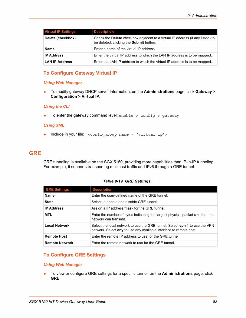
9: Administration
To Configure Gateway Virtual IP
Using Web Manager
To modify gateway DHCP server information, on the Administrations page, click Gateway > Configuration > Virtual IP.
Using the CLI
To enter the gateway command level: enable > config > gateway
Using XML
Include in your file: <configgroup name = "virtual ip">
GRE
GRE tunneling is available on the SGX 5150, providing more capabilities than IP-in-IP tunneling. For example, it supports transporting multicast traffic and IPv6 through a GRE tunnel.
Table 9-19 GRE Settings
To Configure GRE Settings
Using Web Manager
To view or configure GRE settings for a specific tunnel, on the Administrations page, click GRE.
Delete (checkbox) Check the Delete checkbox adjacent to a virtual IP address (if any listed) to be deleted, clicking the Submit button.
Name Enter a name of the virtual IP address.
IP Address Enter the virtual IP address to which the LAN IP address is to be mapped.
LAN IP Address Enter the LAN IP address to which the virtual IP address is to be mapped.
GRE Settings Description
Name Enter the user-defined name of the GRE tunnel.
State Select to enable and disable GRE tunnel.
IP Address Assign a IP address/mask for the GRE tunnel.
MTU Enter the number of bytes indicating the largest physical packet size that the network can transmit.
Local Network Select the local network to use the GRE tunnel. Select vpn 1 to use the VPN network. Select any to use any available interface to remote host.
Remote Host Enter the remote IP address to use for the GRE tunnel.
Remote Network Enter the remote network to use for the GRE tunnel.
Virtual IP Settings Description
SGX 5150 IoT Device Gateway User Guide 88

9: Administration
Using the CLI
To enter GRE command level: enable > gre
Using XML
Include in your file: <configgroup name=”gre”>
Host
Table 9-20 Host Settings
To Configure Host Settings
Note: The following section describes the steps to view and configure Host 1 settings; these steps apply to other host instances of the device.
Using Web Manager
To configure a particular Host, on the Administrations page, click Host > Configuration.
Using the CLI
To enter the Host command level: enable > config > host 1
Using XML
Include in your file: <configgroup name=”host” instance=”1”>
Host Settings Description
Name Enter a name for the host. This name appears on the Login Connect Menu. To
leave a host out of the menu, leave this field blank.
Protocol Select the protocol to use to connect to the host. Choices are: Telnet SSH
Note: SSH keys must be loaded or created on the SSH page for the SSH
protocol to work.
SSH Username Appears if you selected SSH as the protocol. Enter a username to select a preconfigured Username/Password/Key (configured on the SSH: Client Users page), or leave it blank to be prompted for a username and password at connect time.
Note: This configuration option is only available when SSH is selected for Protocol.
Remote Address Enter an IP address for the host to which the device will connect.
Remote Port Enter the port on the host to which the device will connect.
SGX 5150 IoT Device Gateway User Guide 89
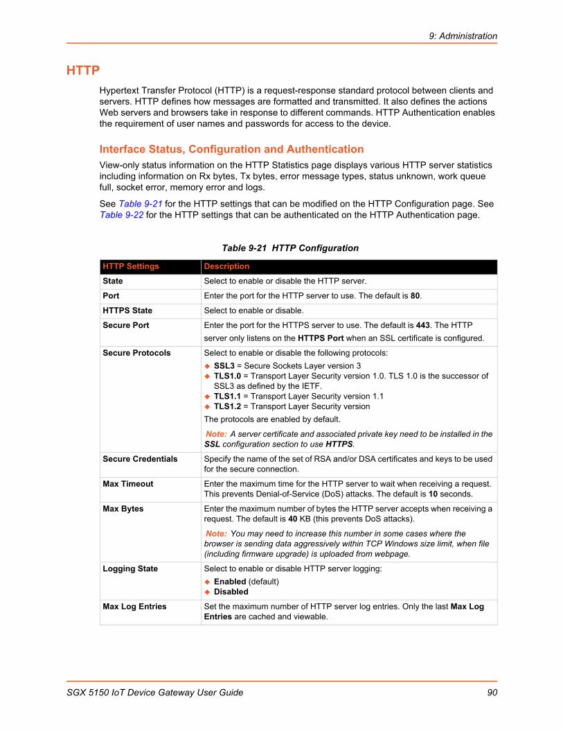
9: Administration
HTTP
Hypertext Transfer Protocol (HTTP) is a request-response standard protocol between clients and servers. HTTP defines how messages are formatted and transmitted. It also defines the actions Web servers and browsers take in response to different commands. HTTP Authentication enables the requirement of user names and passwords for access to the device.
Interface Status, Configuration and AuthenticationView-only status information on the HTTP Statistics page displays various HTTP server statistics including information on Rx bytes, Tx bytes, error message types, status unknown, work queue full, socket error, memory error and logs.
See Table 9-21 for the HTTP settings that can be modified on the HTTP Configuration page. See Table 9-22 for the HTTP settings that can be authenticated on the HTTP Authentication page.
Table 9-21 HTTP Configuration
HTTP Settings Description
State Select to enable or disable the HTTP server.
Port Enter the port for the HTTP server to use. The default is 80.
HTTPS State Select to enable or disable.
Secure Port Enter the port for the HTTPS server to use. The default is 443. The HTTP
server only listens on the HTTPS Port when an SSL certificate is configured.
Secure Protocols Select to enable or disable the following protocols:
SSL3 = Secure Sockets Layer version 3 TLS1.0 = Transport Layer Security version 1.0. TLS 1.0 is the successor of
SSL3 as defined by the IETF. TLS1.1 = Transport Layer Security version 1.1 TLS1.2 = Transport Layer Security version
The protocols are enabled by default.
Note: A server certificate and associated private key need to be installed in the SSL configuration section to use HTTPS.
Secure Credentials Specify the name of the set of RSA and/or DSA certificates and keys to be used for the secure connection.
Max Timeout Enter the maximum time for the HTTP server to wait when receiving a request. This prevents Denial-of-Service (DoS) attacks. The default is 10 seconds.
Max Bytes Enter the maximum number of bytes the HTTP server accepts when receiving a request. The default is 40 KB (this prevents DoS attacks).
Note: You may need to increase this number in some cases where the browser is sending data aggressively within TCP Windows size limit, when file (including firmware upgrade) is uploaded from webpage.
Logging State Select to enable or disable HTTP server logging:
Enabled (default) Disabled
Max Log Entries Set the maximum number of HTTP server log entries. Only the last Max Log Entries are cached and viewable.
SGX 5150 IoT Device Gateway User Guide 90
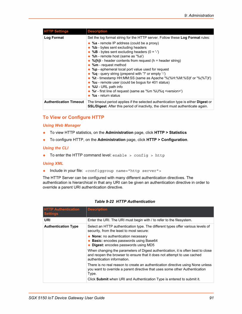
9: Administration
To View or Configure HTTP
Using Web Manager
To view HTTP statistics, on the Administration page, click HTTP > Statistics
To configure HTTP, on the Administration page, click HTTP > Configuration.
Using the CLI
To enter the HTTP command level: enable > config > http
Using XML
Include in your file: <configgroup name="http server">
The HTTP Server can be configured with many different authentication directives. The authentication is hierarchical in that any URI can be given an authentication directive in order to override a parent URI authentication directive.
Table 9-22 HTTP Authentication
Log Format Set the log format string for the HTTP server. Follow these Log Format rules:
%a - remote IP address (could be a proxy) %b - bytes sent excluding headers %B - bytes sent excluding headers (0 = '-') %h - remote host (same as '%a') %hi - header contents from request (h = header string) %m - request method %p - ephemeral local port value used for request %q - query string (prepend with '?' or empty '-') %t - timestamp HH:MM:SS (same as Apache '%(%H:%M:%S)t' or '%(%T)t') %u - remote user (could be bogus for 401 status) %U - URL path info %r - first line of request (same as '%m %U%q <version>') %s - return status
Authentication Timeout The timeout period applies if the selected authentication type is either Digest or SSL/Digest. After this period of inactivity, the client must authenticate again.
HTTP Authentication Settings
Description
URI Enter the URI. The URI must begin with / to refer to the filesystem.
Authentication Type Select an HTTP authentication type. The different types offer various levels of security, from the least to most secure:
None: no authentication necessary Basic: encodes passwords using Base64 Digest: encodes passwords using MD5
When changing the parameters of Digest authentication, it is often best to close and reopen the browser to ensure that it does not attempt to use cached authentication information.
There is no real reason to create an authentication directive using None unless you want to override a parent directive that uses some other Authentication Type.
Click Submit when URI and Authentication Type is entered to submit it.
HTTP Settings Description
SGX 5150 IoT Device Gateway User Guide 91
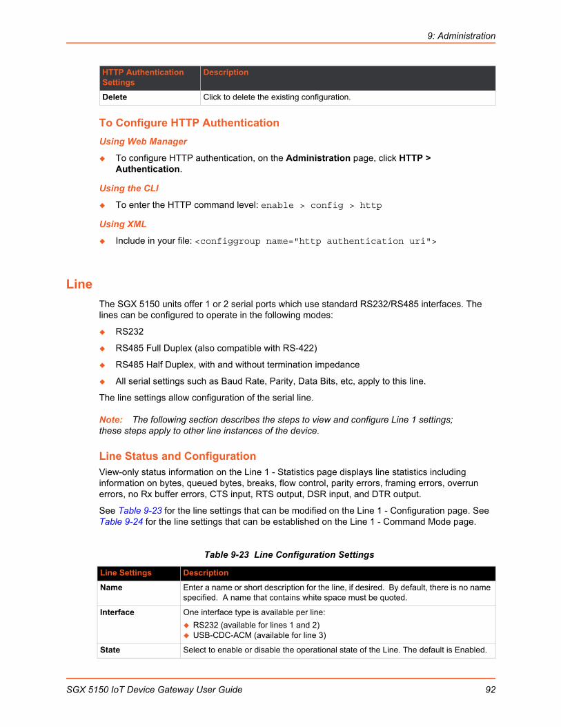
9: Administration
To Configure HTTP Authentication
Using Web Manager
To configure HTTP authentication, on the Administration page, click HTTP > Authentication.
Using the CLI
To enter the HTTP command level: enable > config > http
Using XML
Include in your file: <configgroup name="http authentication uri">
Line
The SGX 5150 units offer 1 or 2 serial ports which use standard RS232/RS485 interfaces. The lines can be configured to operate in the following modes:
RS232
RS485 Full Duplex (also compatible with RS-422)
RS485 Half Duplex, with and without termination impedance
All serial settings such as Baud Rate, Parity, Data Bits, etc, apply to this line.
The line settings allow configuration of the serial line.
Note: The following section describes the steps to view and configure Line 1 settings; these steps apply to other line instances of the device.
Line Status and ConfigurationView-only status information on the Line 1 - Statistics page displays line statistics including information on bytes, queued bytes, breaks, flow control, parity errors, framing errors, overrun errors, no Rx buffer errors, CTS input, RTS output, DSR input, and DTR output.
See Table 9-23 for the line settings that can be modified on the Line 1 - Configuration page. See Table 9-24 for the line settings that can be established on the Line 1 - Command Mode page.
Table 9-23 Line Configuration Settings
Delete Click to delete the existing configuration.
Line Settings Description
Name Enter a name or short description for the line, if desired. By default, there is no name specified. A name that contains white space must be quoted.
Interface One interface type is available per line:
RS232 (available for lines 1 and 2) USB-CDC-ACM (available for line 3)
State Select to enable or disable the operational state of the Line. The default is Enabled.
HTTP Authentication Settings
Description
SGX 5150 IoT Device Gateway User Guide 92

9: Administration
Table 9-24 Line Command Mode Setting
Protocol Set the operational protocol for the Line. The default is Tunnel. Choices are:
None Modbus RTU Modbus ASCII Tunnel
Note: The Line currently only supports None so can be used in Command Mode, for CLI. Tunnel, as in serial-networking tunneling protocol, will be supported in a future software release.
Baud Rate Select the desired baud rate from the drop-down menu.
Parity Select parity from the drop-down menu: None, Even or Odd.
Data Bits Select data bits from the drop-down menu: 7 or 8.
Stop Bits Select 1 or 2 stop bits from the drop-down menu.
Flow Control Select None, Hardware or Software flow control from the drop-down menu.
Gap Timer Set the gap timer delay to set the number of milliseconds to pass from the last character received before the driver forwards the received serial bytes. By default, the delay is four character periods at the current baud rate (minimum 1 msec). Gap timer range is 1 to 5000 milliseconds (default value is 4000 msec).
Threshold Set the number of threshold bytes which need to be received in order for the driver to forward received characters. Default value is 56 bytes.
Line Command Mode Settings
Description
Mode Set the Command Mode state of the Line. When in Command Mode, a CLI session operates exclusively on the Line. Choices are:
Always User Serial String Disabled
Note: In order to enable Command Mode on the Line, Tunneling on the Line must be Disabled (both Connect and Accept modes). Also, custom baud rates are not supported in Command Mode.
Wait Time Enter the amount of time to wait during boot time for the Serial String. This timer starts right after the Signon Message has been sent on the Serial Line and applies only if mode is “Use Serial String”.
Note: This field becomes available when Use Serial String is selected for Mode.
Serial String Enter the Text or Binary string of bytes that must be read on the Serial Line during boot time in order to enable Command Mode. It may contain a time element to specify a required delay in milliseconds x, formed as x. Applies only if mode is “User Serial String”. It may contain a binary character(s) of the form [x]. For example, use decimal [12] or hex [0xc].
Note: This field becomes available when Use Serial String is selected for Mode.
Echo Serial String Select Enable or Disable for Echo Serial String. Applies only if mode is “User Serial String”. Select enable to echo received characters backed out on the line while looking for the serial string.
Note: This field becomes available when Use Serial String is selected for Mode.
Line Settings Description
SGX 5150 IoT Device Gateway User Guide 93
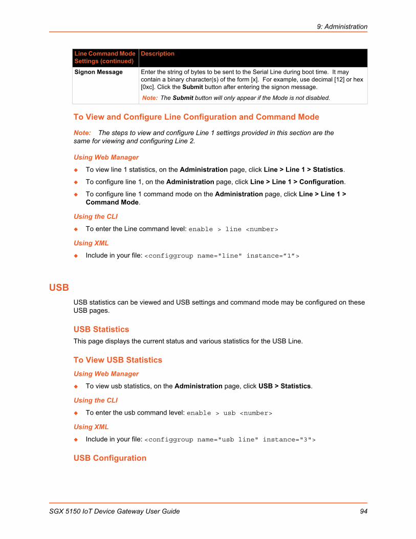
9: Administration
To View and Configure Line Configuration and Command Mode
Note: The steps to view and configure Line 1 settings provided in this section are the same for viewing and configuring Line 2.
Using Web Manager
To view line 1 statistics, on the Administration page, click Line > Line 1 > Statistics.
To configure line 1, on the Administration page, click Line > Line 1 > Configuration.
To configure line 1 command mode on the Administration page, click Line > Line 1 > Command Mode.
Using the CLI
To enter the Line command level: enable > line <number>
Using XML
Include in your file: <configgroup name="line" instance=”1”>
USB
USB statistics can be viewed and USB settings and command mode may be configured on these USB pages.
USB StatisticsThis page displays the current status and various statistics for the USB Line.
To View USB Statistics
Using Web Manager
To view usb statistics, on the Administration page, click USB > Statistics.
Using the CLI
To enter the usb command level: enable > usb <number>
Using XML
Include in your file: <configgroup name="usb line" instance="3">
USB Configuration
Signon Message Enter the string of bytes to be sent to the Serial Line during boot time. It may contain a binary character(s) of the form [x]. For example, use decimal [12] or hex [0xc]. Click the Submit button after entering the signon message.
Note: The Submit button will only appear if the Mode is not disabled.
Line Command Mode Settings (continued)
Description
SGX 5150 IoT Device Gateway User Guide 94

9: Administration
This page displays the current configuration of the USB Line. Changing any of the fields takes effect immediately. Further configuration is available at Wired Network (USB) for 'Ethernet Device' mode.
Table 9-25 USB Configuration
To Configure USB Settings
Using Web Manager
To configure usb settings, on the Administration page, click USB > Configuration.
Using the CLI
To enter the usb command level: enable > usb
Using XML
Include in your file: <configgroup name="usb">
USB Command Mode
Table 9-26 USB Command Mode
USB Settings Description
Name Enter the Name of the USB line. Named lines appear in the 'Login Connect Menu', if enabled. Set it blank to leave it out of the menu.
Interface Select the Interface from the drop-down menu.
State Select to enable or disable the State.
Protocol Select type of Protocol from the drop-down menu: Tunnel or None.
Line Mode Select the USB port mode from the drop-down menu. The USB port can be configured in one of the following: Ethernet Device, Serial Device, or Host. Host mode supports connecting Mass Storage and Serial devices.
Gap Timer Indicate the gap time in milliseconds. The driver forwards received serial bytes after the Gap Timer delay from the last character received. By default, the delay is four character periods at the current baud rate (minimum 1 ms).
Threshold Enter the threshold in bytes. The driver will forward received characters after threshold bytes have been received.
USB Command Mode Settings
Description
Mode When Command Mode is enabled, the Command Line Interface (CLI) is attached to the USB Line. Command Mode can be enabled in a number of ways:
The Always choice immediately enables Command Mode for the USB Line. The Use Serial String choice enables Command Mode when the Serial String is
read on the USB Line during boot time. Disabled
Wait Time Enter the Wait Time in milliseconds. The specified time defines the amount of time to wait during boot time for the Serial String. This timer starts right after the Signon Message has been sent on the USB Line.
SGX 5150 IoT Device Gateway User Guide 95
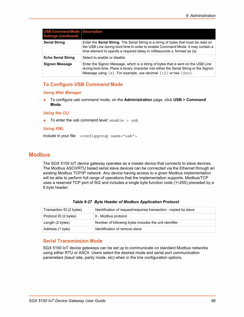
9: Administration
To Configure USB Command Mode
Using Web Manager
To configure usb command mode, on the Administration page, click USB > Command Mode.
Using the CLI
To enter the usb command level: enable > usb
Using XML
Include in your file: <configgroup name="usb">
Modbus
The SGX 5150 IoT device gateway operates as a master device that connects to slave devices. The Modbus ASCII/RTU based serial slave devices can be connected via the Ethernet through an existing Modbus TCP/IP network. Any device having access to a given Modbus implementation will be able to perform full range of operations that the implementation supports. Modbus/TCP uses a reserved TCP port of 502 and includes a single byte function code (1=255) preceded by a 6 byte header:
Table 9-27 Byte Header of Modbus Application Protocol
Serial Transmission ModeSGX 5150 IoT device gateways can be set up to communicate on standard Modbus networks using either RTU or ASCII. Users select the desired mode and serial port communication parameters (baud rate, parity mode, etc) when in the line configuration options.
Serial String Enter the Serial String. The Serial String is a string of bytes that must be read on the USB Line during boot time in order to enable Command Mode. It may contain a time element to specify a required delay in milliseconds x, formed as x.
Echo Serial String Select to enable or disable.
Signon Message Enter the Signon Message, which is a string of bytes that is sent on the USB Line during boot time. Place a binary character into either the Serial String or the Signon Message using [x]. For example, use decimal [12] or hex [0xc].
Transaction ID (2 bytes) Identification of request/response transaction - copied by slave
Protocol ID (2 bytes) 0 - Modbus protocol
Length (2 bytes) Number of following bytes includes the unit identifier
Address (1 byte) Identification of remove slave
USB Command Mode Settings (continued)
Description
SGX 5150 IoT Device Gateway User Guide 96

9: Administration
Table 9-28 Modbus Transmission Modes
The Modbus web pages allow you to check Modbus status and make configuration changes.
Modbus StatisticsThis read-only web page displays the current connection status of the Modbus servers listening on the TCP ports. When a connection is active, the remote client information is displayed as well as the number of PDUs that have been sent and received. Additionally, a Kill link will be present which can be used to kill the connection.
Modbus ConfigurationThis web page shows the current negotiated Modbus settings and allows configuration changes.
Table 9-29 Modbus Configuration
Note: The serial line protocol must also be configured for Modbus, in addition to configuring the Modbus server. See Line (on page 92) and Tunnel (on page 112) for details.
To View and Configure the Modbus Server
Using Web Manager
To view Modbus statistics, on the Administration page, click Modbus > Statistics.
To configure Modbus settings, on the Administration page, click Modbus > Configuration.
Using the CLI
To enter the Modbus command level: enable > configure > modbus
Using XML
Include in your file: <configgroup name=”modbus">
RTU ASCII
Address: 8 bits (0 to 247 decimal, 0 is used for broadcast) Function: 8 bits (1 to 255, 0 is not valid) Data: N X 8 bits (N=0 to 252 bytes) CRC Check: 16 bits
Address: 2 CHARS Function: 2 CHARS Data: N CHARS (N=0 to 252 CHARS) LRC Check: 2 CHARS
Modbus Configuration Settings
Description
TCP Server State Select On or Off. If On, the Modbus server is active on TCP 502.
Additional TCP Server Port Enter the Additional TCP Server Port, if any.
Note: If present, is used in addition to TCP port 502.
Response Timeout Enter the number of milliseconds to wait for a response on the serial side. The device returns exception code 11 to the network master controller if the slave serial device fails to reply within this time out.
SGX 5150 IoT Device Gateway User Guide 97

9: Administration
SMTP
Table 9-30 SMTP Settings
To Configure SMTP Settings
Using Web Manager
To configure SMTP protocol settings, on the Administration page, click SMTP in the menu.
Using the CLI
To enter the command level: enable > config > smtp
Using XML
Include in your file: <configgroup name=”smtp”>
SNMP Settings
Simple Network Management Protocol (SNMP) settings may be viewed and configured in this section.
Table 9-31 SNMP Settings
SMTP Settings Description
From Address Enter the From Address here. This is an email address and is required. If you wish to direct oubtound email messages through a mail server, put your client email address here.
Server Address Enter the Server Address to direct outbound email messages through a mail server.
Server Port Enter the SMTP server port number. The default is 25
Username Enter a Username to direct outbound email messages through a mail server.
Password Enter a Password to direct outbound email messages through a mail server.
Overriding Domain Enter the domain name to override the current domain name in EHLO (Extended Hello).
SNMP Settings Description
State Select to enable or disable the SNMP agent state.
Version Select the SNMP version used by the SNMP agent.
Read Community Specify the read community used by the agent (defaults to public community).
Write Community Specify the write community used by the agent (defaults to private community).
System Contact Specify the system contact.
System Name Update the system name, as necessary. The default system name is .
SGX 5150 IoT Device Gateway User Guide 98

9: Administration
To Configure SNMP Settings
Using Web Manager
To configure SNMP, on the Administration page, click SNMP in the menu.
Using the CLI
To enter the SNMP command level: enable > config > snmp
Using XML
Include in your file: <configgroup name=”snmp”>
SSH
SSH is a network protocol for securely accessing a remote device over an encrypted channel. This protocol manages the security of internet data transmission between two hosts over a network by providing encryption, authentication, and message integrity services.
Configuration is required when the SGX 5150 device is either (1) the SSH server or (2) an SSH client.. The SSH server is used by the CLI (Command Mode) and for tunneling in Accept Mode. The SSH client is for tunneling in Connect Mode.
To configure the SGX 5150 as an SSH server, there are two requirements:
Defined Host Keys: both private and public keys are required. These keys are used for the Diffie-Hellman key exchange (used for the underlying encryption protocol).
Defined Users: these users are permitted to connect to the SGX 5150 SSH server.
SSH Server: Host KeysThe SSH Server Host Keys are used by all applications that play the role of an SSH Server. Specifically Tunneling in Accept Mode. These keys can be created elsewhere and uploaded to the device or automatically generated on the device.
System Description Update the system description, as necessary. The default system information includes the manufacturer name, model name, version and the serial number of the device.
System Location Specify a system location for the SNMP setting.
Primary Destination Enter the primary destination address of the SNMP trap.
Secondary Destination
Enter the secondary destination address of the SNMP trap.
Lantronix MIB File Click the Lantronix MIB file name to save and load it into the MIB browser and trap receiver. This is the base MIB file for Lantronix products. Load or compile this file first.
MIB File Click the MIB file name to save and load it into the MIB browser and trap receiver. This is the product specific MIB file. Load or compile this after the Lantronix MIB File.
SNMP Settings Description
SGX 5150 IoT Device Gateway User Guide 99
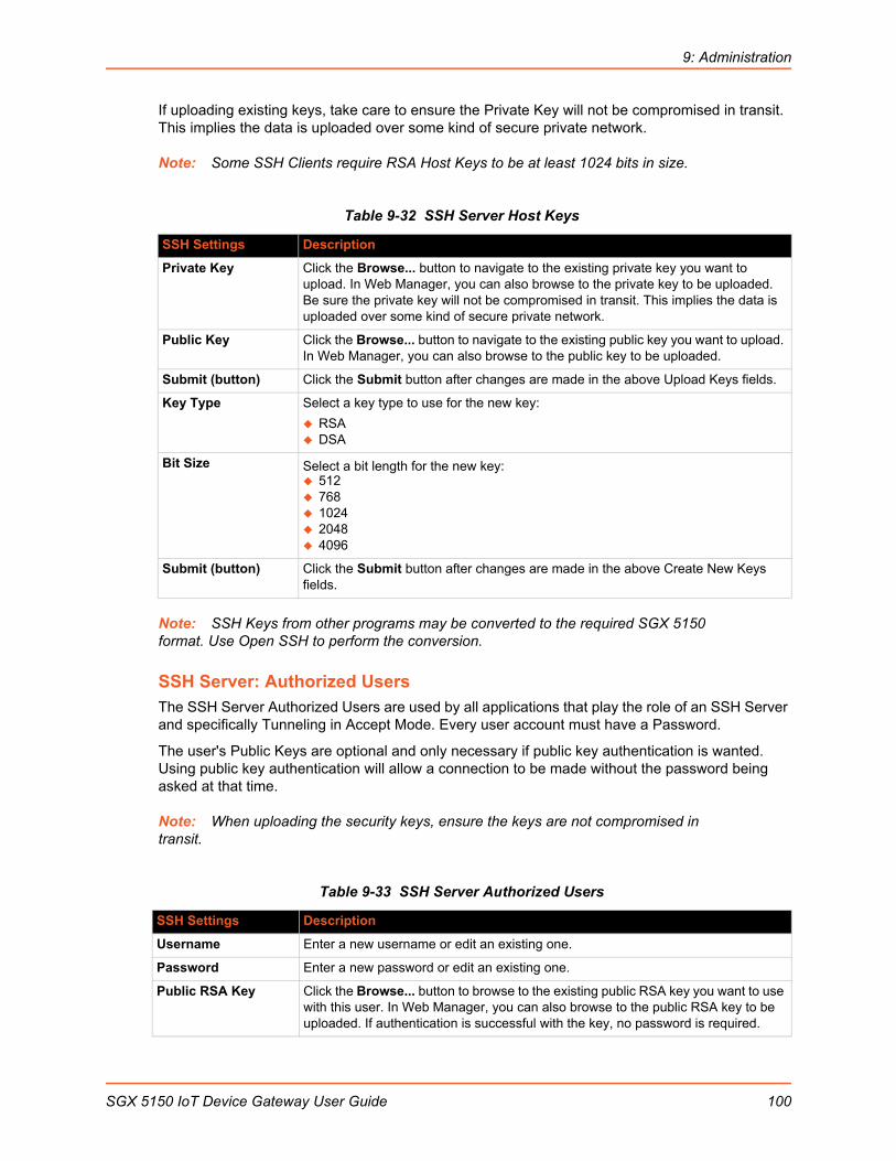
9: Administration
If uploading existing keys, take care to ensure the Private Key will not be compromised in transit. This implies the data is uploaded over some kind of secure private network.
Note: Some SSH Clients require RSA Host Keys to be at least 1024 bits in size.
Table 9-32 SSH Server Host Keys
Note: SSH Keys from other programs may be converted to the required SGX 5150 format. Use Open SSH to perform the conversion.
SSH Server: Authorized UsersThe SSH Server Authorized Users are used by all applications that play the role of an SSH Server and specifically Tunneling in Accept Mode. Every user account must have a Password.
The user's Public Keys are optional and only necessary if public key authentication is wanted. Using public key authentication will allow a connection to be made without the password being asked at that time.
Note: When uploading the security keys, ensure the keys are not compromised in transit.
Table 9-33 SSH Server Authorized Users
SSH Settings Description
Private Key Click the Browse... button to navigate to the existing private key you want to upload. In Web Manager, you can also browse to the private key to be uploaded. Be sure the private key will not be compromised in transit. This implies the data is uploaded over some kind of secure private network.
Public Key Click the Browse... button to navigate to the existing public key you want to upload. In Web Manager, you can also browse to the public key to be uploaded.
Submit (button) Click the Submit button after changes are made in the above Upload Keys fields.
Key Type Select a key type to use for the new key:
RSA DSA
Bit Size Select a bit length for the new key: 512 768 1024 2048 4096
Submit (button) Click the Submit button after changes are made in the above Create New Keys fields.
SSH Settings Description
Username Enter a new username or edit an existing one.
Password Enter a new password or edit an existing one.
Public RSA Key Click the Browse... button to browse to the existing public RSA key you want to use with this user. In Web Manager, you can also browse to the public RSA key to be uploaded. If authentication is successful with the key, no password is required.
SGX 5150 IoT Device Gateway User Guide 100

9: Administration
SSH Client: Known HostsThe SSH Client Known Hosts are used by all applications that play the role of an SSH Client. Specifically in Connect Mode. Configuring these public keys are optional, but if they exist another layer of security is offered which helps prevent Man-in-the-Middle (MITM) attacks.
Table 9-34 SSH Client Known Hosts
Note: These settings are not required for communication. They protect against Man-In-The-Middle (MITM) attacks.
SSH Client: UsersThe SSH Client Users are used by all applications that play the role of an SSH Client. Specifically Tunneling in Connect Mode. To configure the SGX 5150 as an SSH client, an SSH client user must be both configured and also exist on the remote SSH server.
At the very least, a Password or Key Pair must be configured for a user. The keys for public key authentication can be created elsewhere and uploaded to the device or automatically generated on the device.
If uploading existing Keys, take care to ensure the Private Key will not be compromised in transit. This implies the data is uploaded over some kind of secure private network.
The default Remote Command is '<Default login shell>' which tells the SSH Server to execute a remote shell upon connection. This can be changed to anything the SSH Server on the remote host can execute.
Note: If you are providing a key by uploading a file, make sure that the key is not password protected.
Public DSA Key Click the Browse... button to browse to the existing public DSA key you want to use with this user. In Web Manager, you can also browse to the public DSA key to be uploaded.If authentication is successful with the key, no password is required.
Add/Edit (button) Click the Add/Edit button after changes are made in the above SSH Server: Authorized Users fields.
SSH Settings Description
Server Specify either a DNS Hostname or IP Address when adding public host keys for a Server. This Server name should match the name used as the Remote Address in Connect Mode Tunneling.
Public RSA Key Click the Browse... button to browse to the existing public RSA key you want to use with this user. In Web Manager, you can also browse to the public RSA key to be uploaded. If authentication is successful with the key, no password is required.
Public DSA Key Click the Browse... button to browse to the existing public DSA key you want to use with this user. In Web Manager, you can also browse to the public DSA key to be uploaded. If authentication is successful with the key, no password is required.
Submit (button) Click the Submit button after changes are made in the above SSH Server: Known Hosts fields.
SSH Settings Description
SGX 5150 IoT Device Gateway User Guide 101

9: Administration
Table 9-35 SSH Client Users
Table 9-36 Create New Keys
SSH Settings Description
Username Enter the name that the device uses to connect to an SSH server.
Password Enter the password associated with the username.
Remote Command Enter the command that can be executed remotely. Default is shell, which tells the SSH server to execute a remote shell upon connection. This command can be changed to anything the remote host can perform.
Private Key Click the Browse... button to browse to the existing private key you want to upload by clicking the Choose File button. In Web Manager, you can also browse to the private key to be uploaded. Be sure the private key will not be compromised in transit. This implies the data is uploaded over some kind of secure private network.
Public Key Click the Browse... button to browse to the existing public key you want to upload by clicking the Choose File button. In Web Manager, you can also browse to the public key to be uploaded.
Key Type Select a bit length for the key:
RSA DSA
Add/Edit (button) Click the Add/Edit button after changes are made in the above SSH Server: Users fields.
Public Key Click the Browse... button to browse to the existing public key you want to upload by clicking the Choose File button. In Web Manager, you can also browse to the public key to be uploaded.
SSH Setting Description
Key Type Select a bit length for the new key:
RSA DSA
Bit Size Select the bit length of the new key:
512 768 1024 2048 4096
Using a larger bit size takes more time to generate the key. Approximate times are:
1 second for a 512 bit RSA key 1 second for a 768 bit RSA key 1 second for a 1024 bit RSA key 2 seconds for a 512 bit DSA key 2 seconds for a 768 bit DSA key 20 seconds for a 1024 bit DSA key
Note: Some SSH clients require RSA host keys to be at least 1024 bits long. This device generates keys up to 2048 bits long.
Submit (button) Click the Submit button after changes are made in the above Create New Keys fields.
SGX 5150 IoT Device Gateway User Guide 102
9: Administration
To Configure SSH Settings
Using Web Manager
To configure SSH, on the Administration page, click SSH in the menu.
Using the CLI
To enter the SSH command level: enable > ssh
Using XML
Include in your file: <configgroup name=”ssh”>
Include in your file: <configgroup name=”ssh client”>
Include in your file: <configgroup name=”ssh server”>
SSL
Secure Sockets Layer (SSL) is a protocol that creates an encrypted connection between devices. It also provides authentication and message integrity services. SSL is used widely for secure communication to a Web server, and also for wireless authentication.
SSL certificates identify the SGX 5150 unit to peers and are used with some methods of wireless authentication. Provide a name at upload time to identify certificates on the SGX 5150 unit.
You can upload Certificate and Private key combinations, obtained from an external Certificate Authority (CA), to the SGX 5150 unit. The SGX 5150 unit can also generate self-signed certificates with associated private keys.
CredentialsThe SGX 5150 unit can generate self-signed certificates and their associated keys for both RSA and DSA certificate formats. When you generate certificates, assign them a credential name to help identify them on the SGX 5150 unit. Once you create your credentials, then configure them with the desired certificates.
To Create a New Credential
Using Web Manager
1. In Web Manager, click the Administration tab in the header.
2. Click SSL.
3. Click Credentials.
4. Type the name for your credential in the Create new credential field.
5. Click Submit. The new SSL credential appears in the list.
Using the CLI
To enter the SSL command level: enable > ssl
Using XML
Include in your file: <configgroup name="ssl"
SGX 5150 IoT Device Gateway User Guide 103
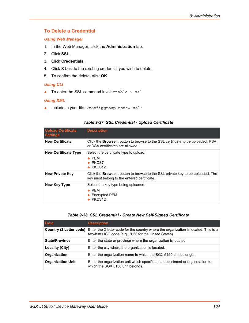
9: Administration
To Delete a Credential
Using Web Manager
1. In the Web Manager, click the Administration tab.
2. Click SSL.
3. Click Credentials.
4. Click X beside the existing credential you wish to delete.
5. To confirm the delete, click OK.
Using CLI
To enter the SSL command level: enable > ssl
Using XML
Include in your file: <configgroup name="ssl"
Table 9-37 SSL Credential - Upload Certificate
Table 9-38 SSL Credential - Create New Self-Signed Certificate
Upload Certificate Settings
Description
New Certificate Click the Browse... button to browse to the SSL certificate to be uploaded. RSA or DSA certificates are allowed.
New Certificate Type Select the certificate type to upload:
PEM PKCS7 PKCS12
New Private Key Click the Browse... button to browse to the SSL private key to be uploaded. The key must belong to the entered certificate.
New Key Type Select the key type being uploaded:
PEM Encrypted PEM PKCS12
Field Description
Country (2 Letter code) Enter the 2 letter code for the country where the organization is located. This is a two-letter ISO code (e.g., “US” for the United States).
State/Province Enter the state or province where the organization is located.
Locality (City) Enter the city where the organization is located.
Organization Enter the organization name to which the SGX 5150 unit belongs.
Organization Unit Enter the organization unit which specifies the department or organization to which the SGX 5150 unit belongs.
SGX 5150 IoT Device Gateway User Guide 104

9: Administration
To Configure an SSL Credential to Use an Uploaded Certificate1. In the Web Manager, click the Administration tab.
2. Click SSL.
3. Click Credentials.
4. Under the View or Edit heading, click the credential that you want to modify to access the information page for that credential.
5. To upload a New Certificate to assign to the credential, click Browse... beside New Certificate, locate the valid certificate, then double-click the file to select it.
6. Identify the New Certificate Type selected.
If you select SSL authority, RSA, or DSA certificates, select PEM or PKCS7.
If the Web Manager determines that the certificate is an Authority Certificate type, the New Certificate Type field updates to PKCS12 automatically. For PKCS12 certificates, enter a password.
Note: Ensure that the certificate is formatted properly with a valid open and close tag. Also ensure that the Private Key is associated to the selected certificate and that it is formatted properly with a valid open and close tag.
7. To locate the associated valid New Private Key for this certificate, click Browse... to browse to and select the file.
8. Select the New Key Type from the drop-down menu.
9. Click Submit.
To Configure an SSL Credential to Use a Self-Signed Certificate1. In the Web Manager, click the Administration tab.
2. Click SSL.
3. Click Credentials.
4. Under View or Edit, click the credential you wish to modify to access the information page for that credential.
5. Enter the details for a new self-signed certificate for this credential. Reference Table 9-38 SSL Credential - Create New Self-Signed Certificate on page 104.
6. Click Submit. The process to create a self-signed certificate can take up to 30 seconds, depending on the length of the key.
Common Name Enter a network name for the SGX 5150 unit when installed in the user’s network (usually the fully qualified domain name). It is identical to the name that is used to access the SGX 5150 unit with a web browser without the prefix http://. In case the name given here and the actual network name differ, the browser will pop up a security warning when the SGX 5150 unit is accessed using HTTPS.
Expires Type the date that the self-signed certificate expires in mm/dd/yyyy format.
Type Select RSA or DSA.
Key length Select the key length from the drop-down menu.
Field Description
SGX 5150 IoT Device Gateway User Guide 105

9: Administration
Trusted AuthoritiesOne or more authority certificates are used to verify the identity of a peer. Authority certificates are used with some wireless authentication methods. These certificates do not require a private key.
Table 9-39 SSL Trusted Authority
To Upload an Authority CertificateYou can upload SSL authority, RSA, or DSA certificates.
To upload a trusted authority certificate:
1. In the Web Manager, click the Administration tab.
2. Click SSL.
3. Click Trusted Authorities.
4. Click Browse... to browse to and select an authority certificate.
5. Select the New Certificate Type from the drop-down window:
If you select SSL authority, RSA, or DSA certificates, select PEM or PKCS7.
If the Web Manager determines that the certificate is an authority certificate type, the field updates to PKCS12 automatically. For PKCS12 certificates, type a Password.
Notes:
Ensure that the certificate is formatted properly with a valid open and close tag.
Ensure that the Private Key is associated to the selected certificate and that it is formatted properly with a valid open and close tag.
If the New Certificate field is set to None, the certificate is not supported.
6. Click Submit.
Trusted Authorities Settings
Description
Authority Click the Browse... button to browse to an existing SSL authority certificate.
RSA or DSA certificates are allowed.
The format of the authority certificate can be PEM or PKCS7. PEM files must start with “-----BEGIN CERTIFICATE-----” and end with “-----END CERTIFICATE-----”. Some certificate authorities add comments before and/or after these lines. Those comments must be deleted before upload.
New Certificate Type Select the certificate type through the drop-down window.
This field may automatically update, depending upon extension of the certificate entered.
Delete All To delete all existing certificate authorities as listed, click the Delete ALL button.
Delete To delete an existing certificate authority, click the Delete button beside the specific authority listed under Current Certificate Authorities.
SGX 5150 IoT Device Gateway User Guide 106

9: Administration
CSR (Certificate Signing Request)The SGX 5150 unit uses the Secure Socket Layer (SSL) protocol for any encrypted network traffic between itself and a connected client. During the connection establishment the SGX 5150 unit has to expose its identity to a client using a cryptographic certificate. Upon leaving the factory this certificate and the underlying secret key is the same for all SGX 5150 units and will not match the network configuration where it is installed. The certificate’s underlying secret key is also used for securing the SSL handshake. Leaving the default certificate unmodified is all right in most circumstances and is necessary only if the network facility is vulnerable to man-in-the-middle attack.
It is possible to generate and install a new base64 encoded x.509 certificate that is unique for a particular SGX 5150 unit. The SGX 5150 unit is able to generate a new cryptographic key and the associated Certificate Signing Request (CSR) that needs to be certified by a certification authority (CA).
To create and install an SSL certificate, perform the following steps.
1. On the Administration page, click SSL > CSR (Certificate Signing Request). The Certificate Signing Request page displays.
2. Modify the following fields:
Table 9-40 SSL CSR (Certificate Signing Request)
3. Click Submit to initiate the Certificate Signing Request generation. After a few moments, the CSR file created will appear.
4. Click the CSR file to download it if desired.
Field Description
Country (2 Letter code) Enter the two-letter ISO code (e.g., US for the United States) for the country where the organization is located.
State/Province Enter the state or province where the organization is located.
Locality (City) Enter the city where the organization is located.
Organization Enter the organization name to which the SGX 5150 unit belongs.
Organization Unit Enter the department within the organization to which the SGX 5150 unit belongs.
Common Name Enter the network name of the SGX 5150 unit once it is installed in the user’s network (usually the fully qualified domain name). It is identical to the name that is used to access the SGX 5150 unit with a web browser without the prefix http://. In case the name given here and the actual network name differ, the browser will pop up a security warning when the SGX 5150 unit is accessed using HTTPS.
Key length Select the key length: 2048 or 4096.
SGX 5150 IoT Device Gateway User Guide 107
9: Administration
Syslog
The system log (Syslog) provides information that shows the current configuration and statistics of the Syslog. You can configure the Syslog host and set the severity level for events to log.
Note: The system log is saved to local storage, but is not retained through reboots unless diagnostics logging to the file system is enabled. To allow the administrator to save the complete system log, save the system log to a server that supports remote logging services. For details, refer to RFC 3164. The default port is 514.
To Configure Syslog Settings
Using Web Manager
1. In the Web Manager, click the Administration tab.
2. Click Syslog.
3. To enable Syslog, for State, select Enabled.
4. For Host, type the IP address of the remote server that stores the logs.
5. For Remote Port, enter the port number for the remote host that supports logging services. The default port number is 514.
6. For Severity Log Level, click the arrow to select the minimum level message type that you want the system to log.
7. Click Submit.
Using CLI
To enter the Syslog command level: enable > configure > syslog
Using XML
Include in your file: <configgroup name="syslog"
SGX 5150 IoT Device Gateway User Guide 108
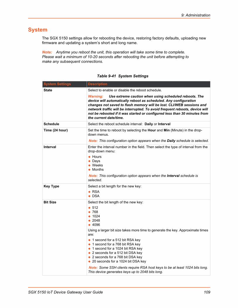
9: Administration
System
The SGX 5150 settings allow for rebooting the device, restoring factory defaults, uploading new firmware and updating a system’s short and long name.
Note: Anytime you reboot the unit, this operation will take some time to complete. Please wait a minimum of 10-20 seconds after rebooting the unit before attempting to make any subsequent connections.
Table 9-41 System Settings
System Settings Description
State Select to enable or disable the reboot schedule.
Warning: Use extreme caution when using scheduled reboots. The device will automatically reboot as scheduled. Any configuration changes not saved to flash memory will be lost. CLI/WEB sessions and network traffic will be interrupted. To avoid frequent reboots, device will not be rebooted if it was started or configured less than 30 minutes from the current date/time.
Schedule Select the reboot schedule interval: Daily or Interval
Time (24 hour) Set the time to reboot by selecting the Hour and Min (Minute) in the drop-down menus.
Note: This configuration option appears when the Daily schedule is selected.
Interval Enter the interval number in the field. Then select the type of interval from the drop-down menu:
Hours Days Weeks Months
Note: This configuration option appears when the Interval schedule is selected.
Key Type Select a bit length for the new key:
RSA DSA
Bit Size Select the bit length of the new key:
512 768 1024 2048 4096
Using a larger bit size takes more time to generate the key. Approximate times are:
1 second for a 512 bit RSA key 1 second for a 768 bit RSA key 1 second for a 1024 bit RSA key 2 seconds for a 512 bit DSA key 2 seconds for a 768 bit DSA key 20 seconds for a 1024 bit DSA key
Note: Some SSH clients require RSA host keys to be at least 1024 bits long. This device generates keys up to 2048 bits long.
SGX 5150 IoT Device Gateway User Guide 109
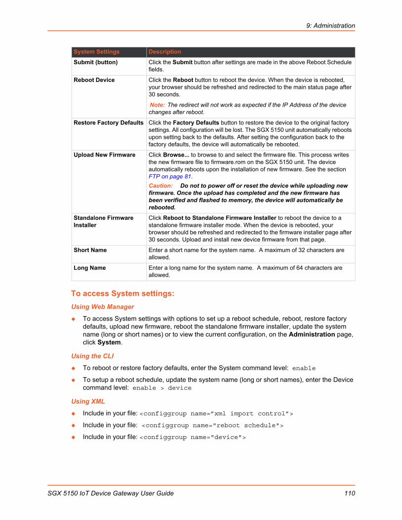
9: Administration
To access System settings:
Using Web Manager
To access System settings with options to set up a reboot schedule, reboot, restore factory defaults, upload new firmware, reboot the standalone firmware installer, update the system name (long or short names) or to view the current configuration, on the Administration page, click System.
Using the CLI
To reboot or restore factory defaults, enter the System command level: enable
To setup a reboot schedule, update the system name (long or short names), enter the Device command level: enable > device
Using XML
Include in your file: <configgroup name=”xml import control”>
Include in your file: <configgroup name="reboot schedule">
Include in your file: <configgroup name="device">
Submit (button) Click the Submit button after settings are made in the above Reboot Schedule fields.
Reboot Device Click the Reboot button to reboot the device. When the device is rebooted, your browser should be refreshed and redirected to the main status page after 30 seconds.
Note: The redirect will not work as expected if the IP Address of the device changes after reboot.
Restore Factory Defaults Click the Factory Defaults button to restore the device to the original factory settings. All configuration will be lost. The SGX 5150 unit automatically reboots upon setting back to the defaults. After setting the configuration back to the factory defaults, the device will automatically be rebooted.
Upload New Firmware Click Browse... to browse to and select the firmware file. This process writes the new firmware file to firmware.rom on the SGX 5150 unit. The device automatically reboots upon the installation of new firmware. See the section FTP on page 81.
Caution: Do not to power off or reset the device while uploading new firmware. Once the upload has completed and the new firmware has been verified and flashed to memory, the device will automatically be rebooted.
Standalone Firmware Installer
Click Reboot to Standalone Firmware Installer to reboot the device to a standalone firmware installer mode. When the device is rebooted, your browser should be refreshed and redirected to the firmware installer page after 30 seconds. Upload and install new device firmware from that page.
Short Name Enter a short name for the system name. A maximum of 32 characters are allowed.
Long Name Enter a long name for the system name. A maximum of 64 characters are allowed.
System Settings Description
SGX 5150 IoT Device Gateway User Guide 110

9: Administration
Terminal
You can configure whether each serial line or the Telnet/SSH server presents a CLI or a Login Connect menu when a connection is made.
Table 9-42 Terminal on Network and Line Settings
To Configure the Terminal Network Connection
Using Web Manager
To configure the Terminal on Network, click Administration in the header and select Terminal > Network.
Using the CLI
To enter the Terminal Network command level: enable > config > terminal network
Using XML
Include in your file: <configgroup name="terminal" instance="network">
Terminal on Network and Line Settings
Description
Terminal Type Enter text to describe the type of terminal. The text will be sent to a host via IAC.
Note: IAC means, “interpret as command.” It is a way to send commands over the network such as send break or start echoing. IAC is only supported in Telnet.
Login Connect Menu Select the interface to display when the user logs in. Choices are:
Enabled = shows the Login Connect Menu. Disabled = shows the CLI (default)
Exit Connect Menu Select whether to display a choice for the user to exit the Login Connect Menu and reach the CLI. Choices are:
Enabled = a choice allows the user to exit to the CLI. Disabled = there is no exit to the CLI (default)
Send Break Enter the Send Break control character received from the network on its way to a serial line which would cause the line output to be forced inactive.
Example setting: <Ctrl> Y
Blank the field to set to <None>.
Note: This field is not available for terminal network configuration.
Break Duration Specify the length of the spacing condition placed on the line when a break is sent.
Note: This field is not available for terminal network configuration.
Echo Select whether to enable echo:
Enabled Disabled
Note: Applies only to Connect Mode Telnet connections, not to Accept Mode. Only disable Echo if your terminal echoes, in which case you will see double of each character typed. Default is enabled.
SGX 5150 IoT Device Gateway User Guide 111
9: Administration
To Configure the Terminal Line or USB Connection
Note: The following section describes the steps to view and configure terminal line 1 settings; these steps apply to terminal line 2 and terminal line 3 of the device.
Using Web Manager
To configure a particular Terminal Line, click Administration in the header and select Terminal > Line 1.
To configure the Terminal USB, click Administration in the header and select Terminal > USB 1.
Using the CLI
To enter the Terminal Line command level: enable > config > terminal 1
Using XML
Include in your file: <configgroup name="terminal" instance="1">
Tunnel
Tunneling allows serial devices to communicate over a network without ‘being aware’ of the devices that establish the network connection between them. Tunneling parameters are configured using the Tunnel menu and submenus. The Tunnel settings allow you to configure how the Serial-Network tunneling operates. Tunneling is available on all serial lines. The connections on one serial line are separate from these on another serial port.
Note: The following section describes the steps to view and configure Tunnel 1 settings; these steps apply to other tunnel instances of the device.
Tunnel StatisticsTunnel statistics contains data counters, error counters, connection time and connection information. Statistics are available at each individual connection and aggregated across all connections.
To View Tunnel Statistics
Using Web Manager
To view statistics for a specific tunnel, on the Administration page, click Tunnel > Tunnel 1 > Statistics.
Using the CLI
To view Tunnel 1 statistics: enable > tunnel 1, show statistics
Using XML
Include in your file: <statusgroup name=”tunnel” instance=”1”>
Serial SettingsThese serial settings for the tunnel apply to the Serial Line interface. The Line Settings and Protocol are displayed for informational purposes and must be configured from the Line settings.
SGX 5150 IoT Device Gateway User Guide 112

9: Administration
Table 9-43 Tunnel Serial Settings
To Configure Tunnel Serial Settings
Using Web Manager
To configure the Serial Settings for a specific tunnel, on the Administration page, click Tunnel > Tunnel 1 > Serial Settings.
Using the CLI
To enter Tunnel 1 command level: enable > tunnel 1 > serial
Using XML
Include in your file: <configgroup name=”tunnel serial” instance=”1”>
Packing ModeWith Packing, data from the serial Line is not sent over the network immediately. Instead, data is queued and sent in segments, when either the timeout or byte threshold is reached. Packing applies to both Accept and Connect Modes.
Table 9-44 Tunnel Packing Mode Settings
Terminal Serial Settings
Description
Line Settings Line Settings information here is display only. Go to the section, To Configure the Terminal Line or USB Connection to modify these settings.
Protocol Protocol information here is display only. Go to the section, To Configure the Terminal Line or USB Connection to modify these settings.
DTR Select the conditions in which the Data Terminal Ready (DTR) control signal on the serial line are asserted. Choices are: Unasserted TruPort = the DTR is asserted whenever either a connect or an accept mode
tunnel connection is active with the Telnet Protocol RFC2217 saying that the remote DSR is asserted.
Asserted while connected = the DTR is asserted whenever either a connect or an accept mode tunnel connection is active.
Continuously asserted
Tunnel Packing Mode Settings
Description
Mode Configure the Tunnel Packing Mode. Choices are: Disable = Data not packed. Timeout = data sent after timeout occurs. Send Character = data sent when the Send Character is read on the Serial
Line.
Threshold Set the threshold (byte count). If the received serial data reaches thisthreshold, then the data will be sent on the network. Valid range is 100 to
1450 bytes. Default is 512.
Note: This configuration option appears when Timeout mode is selected.
SGX 5150 IoT Device Gateway User Guide 113
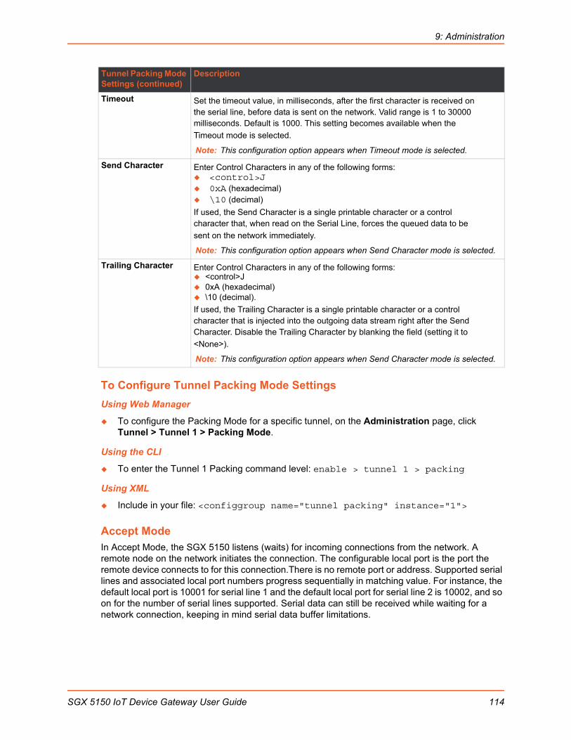
9: Administration
To Configure Tunnel Packing Mode Settings
Using Web Manager
To configure the Packing Mode for a specific tunnel, on the Administration page, click Tunnel > Tunnel 1 > Packing Mode.
Using the CLI
To enter the Tunnel 1 Packing command level: enable > tunnel 1 > packing
Using XML
Include in your file: <configgroup name="tunnel packing" instance="1">
Accept ModeIn Accept Mode, the SGX 5150 listens (waits) for incoming connections from the network. A remote node on the network initiates the connection. The configurable local port is the port the remote device connects to for this connection.There is no remote port or address. Supported serial lines and associated local port numbers progress sequentially in matching value. For instance, the default local port is 10001 for serial line 1 and the default local port for serial line 2 is 10002, and so on for the number of serial lines supported. Serial data can still be received while waiting for a network connection, keeping in mind serial data buffer limitations.
Timeout Set the timeout value, in milliseconds, after the first character is received onthe serial line, before data is sent on the network. Valid range is 1 to 30000milliseconds. Default is 1000. This setting becomes available when the
Timeout mode is selected.
Note: This configuration option appears when Timeout mode is selected.
Send Character Enter Control Characters in any of the following forms: <control>J 0xA (hexadecimal) \10 (decimal)
If used, the Send Character is a single printable character or a controlcharacter that, when read on the Serial Line, forces the queued data to be
sent on the network immediately.
Note: This configuration option appears when Send Character mode is selected.
Trailing Character Enter Control Characters in any of the following forms: <control>J 0xA (hexadecimal) \10 (decimal).
If used, the Trailing Character is a single printable character or a controlcharacter that is injected into the outgoing data stream right after the SendCharacter. Disable the Trailing Character by blanking the field (setting it to
<None>).
Note: This configuration option appears when Send Character mode is selected.
Tunnel Packing Mode Settings (continued)
Description
SGX 5150 IoT Device Gateway User Guide 114
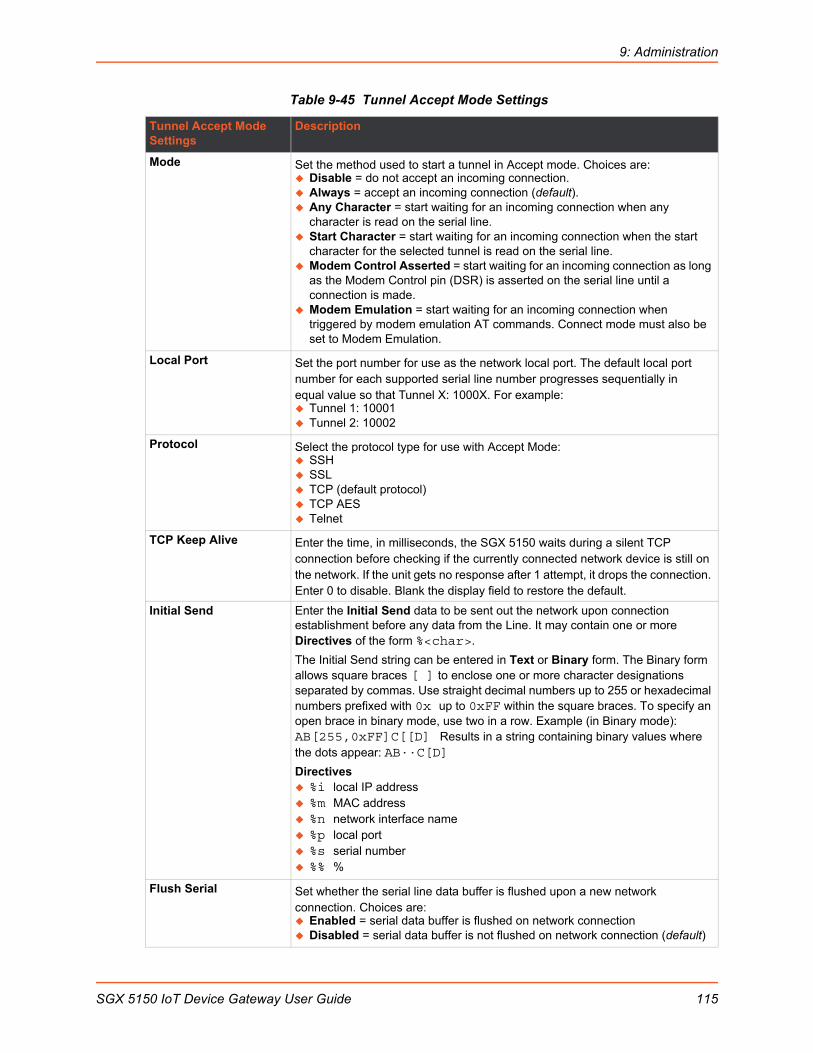
9: Administration
Table 9-45 Tunnel Accept Mode Settings
Tunnel Accept Mode Settings
Description
Mode Set the method used to start a tunnel in Accept mode. Choices are: Disable = do not accept an incoming connection. Always = accept an incoming connection (default). Any Character = start waiting for an incoming connection when any
character is read on the serial line. Start Character = start waiting for an incoming connection when the start
character for the selected tunnel is read on the serial line. Modem Control Asserted = start waiting for an incoming connection as long
as the Modem Control pin (DSR) is asserted on the serial line until a connection is made.
Modem Emulation = start waiting for an incoming connection when triggered by modem emulation AT commands. Connect mode must also be set to Modem Emulation.
Local Port Set the port number for use as the network local port. The default local portnumber for each supported serial line number progresses sequentially inequal value so that Tunnel X: 1000X. For example: Tunnel 1: 10001 Tunnel 2: 10002
Protocol Select the protocol type for use with Accept Mode: SSH SSL TCP (default protocol) TCP AES Telnet
TCP Keep Alive Enter the time, in milliseconds, the SGX 5150 waits during a silent TCP connection before checking if the currently connected network device is still on the network. If the unit gets no response after 1 attempt, it drops the connection. Enter 0 to disable. Blank the display field to restore the default.
Initial Send Enter the Initial Send data to be sent out the network upon connection establishment before any data from the Line. It may contain one or more Directives of the form %<char>.
The Initial Send string can be entered in Text or Binary form. The Binary form allows square braces [ ] to enclose one or more character designations separated by commas. Use straight decimal numbers up to 255 or hexadecimal numbers prefixed with 0x up to 0xFF within the square braces. To specify an open brace in binary mode, use two in a row. Example (in Binary mode): AB[255,0xFF]C[[D]Results in a string containing binary values where the dots appear: AB··C[D]
Directives %i local IP address %m MAC address %n network interface name %p local port %s serial number %% %
Flush Serial Set whether the serial line data buffer is flushed upon a new network connection. Choices are: Enabled = serial data buffer is flushed on network connection Disabled = serial data buffer is not flushed on network connection (default)
SGX 5150 IoT Device Gateway User Guide 115

9: Administration
To Configure Tunnel Accept Mode Settings
Using Web Manager
To configure the Accept Mode for a specific tunnel, on the Administration page, click Tunnel > Tunnel 1 > Accept Mode.
Using the CLI
To enter Tunnel 1 Accept Mode command level: enable > tunnel 1 > accept
Using XML
Include in your file: <configgroup name="tunnel accept" instance="1">
Connect ModeIn Connect Mode, the SGX 5150 continues to attempt an outgoing connection on the network, until established (based on which connection method is selected in the configuration described in Table 9-46). If the connection attempt fails or the connection drops, then it retries after a timeout. The remote node on the network must listen for the Connect Mode’s connection.
For Connect Mode to function, it must be enabled, have a remote station (node) configured, and a remote port configured (TCP or UDP). When established, Connect Mode is always on. Enter the
Block Serial Set whether Block Serial is enabled for debugging purposes. Choices are: Enabled = if Enabled, incoming characters from the serial line will not be
forwarded to the network. Instead, they will be buffered and will eventually flow off the serial line if hardware or software flow control is configured.
Disabled = this is the default setting; incoming characters from the Serial Line are sent on into the network. Any buffered characters are sent first.
Block Network Set whether Block Network is enabled for debugging purposes. Choices are: Enabled = if Enabled, incoming characters from the network will not be
forwarded to the Serial Line. Instead, they will be buffered and will eventually flow off the network side.
Disabled = this is the default setting; incoming characters from the networkare sent on into the Serial Line. Any buffered characters are sent first.
Password Enter a password. This password can be up to 31 characters in length and must contain only alphanumeric characters and punctuation. When set, clients must send the correct password string to the unit within 30 seconds from opening network connection in order to enable data transmission. The password sent to the unit must be terminated with one of the following: 0A (Line Feed) 00 (Null) 0D 0A (Carriage Return/Line Feed) 0D 00 (Carriage Return/Null)
If, Prompt for Password is set to Enabled and a password is provided, the user will be prompted for the password upon connection.
Email on Connect Select an email profile number to which an email notification will be sent upon the establishment of an accept mode tunnel.
Email on Disconnect Select an email profile number to which an email notification will be sent upon the disconnection of an accept mode tunnel.
Tunnel Accept Mode Settings (continued)
Description
SGX 5150 IoT Device Gateway User Guide 116

9: Administration
remote station as an IPv4 or IPv6 address or DNS name. The SGX 5150 will not make a connection unless it can resolve the address. For Connect Mode using UDP, the SGX 5150 accepts packets from any device on the network. It will send packets to the last device that sent it packets.
Note: The port in Connect Mode is not the same port configured in Accept Mode. Telnet protocol is not supported in Tunnels on USB interfaces. The TCP keepalive time is the time in which probes are periodically sent to the other end of the connection. This ensures the other side is still connected.
Table 9-46 Tunnel Connect Mode Settings
Tunnel Connect Mode Settings
Description
Mode Set the method to be used to attempt a connection to a remote host or device.Choices are: Disable = an outgoing connection is never attempted. (default) Always = a connection is attempted until one is made. If the connection gets
disconnected, the device retries until it makes a connection. Any Character = a connection is attempted when any character is read on
the serial line. Start Character = a connection is attempted when the start character for the
selected tunnel is read on the serial line. Modem Control Asserted = a connection is attempted as long as the
Modem Control pin (DSR) is asserted, until a connection is made. Modem Emulation = a connection is attempted when triggered by modem
emulation AT commands.
Local Port Enter an alternative Local Port. The Local Port is set to <Random> by default
but can be overridden. Blank the field to restore the default.
Host 1 Click on the displayed information to expand it for editing. Complete the Host fields that appear according to Table 9-47.
If <None> is displayed, clicking it will allow you to configure a new host. At least one Host is required to enable Connect Mode as this information is necessary to connect to that host. Once you start to edit Host 1, a box for Host 2 will show up. Editing Host 2 will cause a Host 3 box to appear. Up to 32 hosts are available.
Reconnect Timer Set the value of the reconnect timeout (in milliseconds) for outgoing connectionsestablished by the device. Valid range is 1 to 65535 milliseconds. Default is
15000.
Flush Serial Data Set whether the serial Line data buffer is flushed upon a new networkconnection. Choices are: Enabled = serial data buffer is flushed on network connection Disabled = serial data buffer is not flushed on network connection (default)
Block Serial Set whether Block Serial is enabled for debugging purposes. Choices are: Enabled = If Enabled, incoming characters from the Serial Line will not be
forwarded to the network. Instead, they will be buffered and will eventually flow off the Serial Line if hardware or software flow control is configured.
Disabled = this is the default setting; incoming characters from the Serial Line are sent on into the network. Any buffered characters are sent first.
SGX 5150 IoT Device Gateway User Guide 117
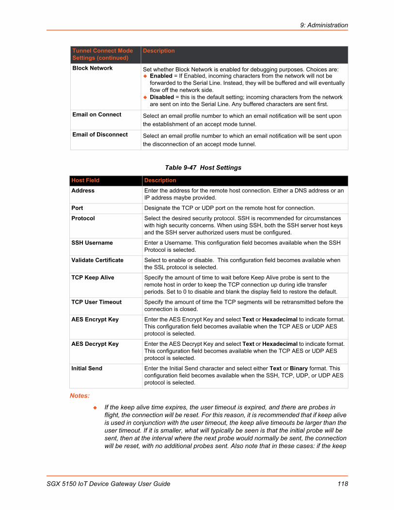
9: Administration
Table 9-47 Host Settings
Notes:
If the keep alive time expires, the user timeout is expired, and there are probes in flight, the connection will be reset. For this reason, it is recommended that if keep alive is used in conjunction with the user timeout, the keep alive timeouts be larger than the user timeout. If it is smaller, what will typically be seen is that the initial probe will be sent, then at the interval where the next probe would normally be sent, the connection will be reset, with no additional probes sent. Also note that in these cases: if the keep
Block Network Set whether Block Network is enabled for debugging purposes. Choices are: Enabled = If Enabled, incoming characters from the network will not be
forwarded to the Serial Line. Instead, they will be buffered and will eventually flow off the network side.
Disabled = this is the default setting; incoming characters from the network are sent on into the Serial Line. Any buffered characters are sent first.
Email on Connect Select an email profile number to which an email notification will be sent upon
the establishment of an accept mode tunnel.
Email of Disconnect Select an email profile number to which an email notification will be sent upon
the disconnection of an accept mode tunnel.
Host Field Description
Address Enter the address for the remote host connection. Either a DNS address or an IP address maybe provided.
Port Designate the TCP or UDP port on the remote host for connection.
Protocol Select the desired security protocol. SSH is recommended for circumstances with high security concerns. When using SSH, both the SSH server host keys and the SSH server authorized users must be configured.
SSH Username Enter a Username. This configuration field becomes available when the SSH Protocol is selected.
Validate Certificate Select to enable or disable. This configuration field becomes available when the SSL protocol is selected.
TCP Keep Alive Specify the amount of time to wait before Keep Alive probe is sent to the remote host in order to keep the TCP connection up during idle transfer periods. Set to 0 to disable and blank the display field to restore the default.
TCP User Timeout Specify the amount of time the TCP segments will be retransmitted before the connection is closed.
AES Encrypt Key Enter the AES Encrypt Key and select Text or Hexadecimal to indicate format. This configuration field becomes available when the TCP AES or UDP AES protocol is selected.
AES Decrypt Key Enter the AES Decrypt Key and select Text or Hexadecimal to indicate format. This configuration field becomes available when the TCP AES or UDP AES protocol is selected.
Initial Send Enter the Initial Send character and select either Text or Binary format. This configuration field becomes available when the SSH, TCP, UDP, or UDP AES protocol is selected.
Tunnel Connect Mode Settings (continued)
Description
SGX 5150 IoT Device Gateway User Guide 118

9: Administration
alive timer is significantly smaller than the user timeout, probes will continue to be sent for an unreachable host until the user timeout expires.
If there is data in flight when the TCP retransmission timeout kicks in, the user timeout is checked as a limiting condition only when the timer expirations would normally be checked during RTO handling. In other words, the user timeout will not be an exact limit; in practice, it will always take somewhat longer for the connection to be closed. The longer the user timeout is, the more likely it will expire between exponentially slower retransmissions, and the connection will not experience an error until the next retransmission timeout is checked. Also note that the user timeout expiration during retransmission returns an error to the application; it does not automatically reset the connection as happens with keep alive timeout. It is up to the application (e.g., tunneling) to close the connection (this happens almost immediately with tunneling).
To Configure Tunnel Connect Mode Settings
Using Web Manager
To configure the Connect Mode for a specific tunnel, on the Administration page, click Tunnel > Tunnel 1 > Connect Mode.
Using the CLI
To enter the Tunnel 1 Connect Mode command level: enable > tunnel 1 > connect
Using XML
Include in your file: <configgroup name="tunnel connect" instance="1">
Connecting Multiple HostsIf more than one host is configured, a Host Mode option appears. Host Mode controls how multiple hosts will be accessed. For the SGX 5150, the Connect Mode supports up to 32 hosts. Hosts may be accessed sequentially or simultaneously:
Sequential – Sequential host lists establish a prioritized list of tunnels. The host specified as Host 1 will be attempted first. If that fails, it will proceed to Host 2, 3, etc, in the order they are specified. When a connection drops, the cycle starts again with Host 1 and proceeds in order. Establishing the host order is accomplished with host list promotion (see Host List Promotion on page 119). Sequential is the default Host Mode.
Simultaneous – A tunnel will connect to all hosts accepting a connection. Simultaneous connections occur at the same time to all listed hosts. The device can support a maximum of 64 total aggregate connections.
Host List PromotionThis feature allows Host IP promotion of individual hosts in the overall sequence.
To promote a specific Host:
1. Click the icon in the desired Host field, for example Host 2 and Host 3.
2. The selected Host(s) exchanges its place with the Host above it.
3. Click Submit. The hosts change sequence.
SGX 5150 IoT Device Gateway User Guide 119
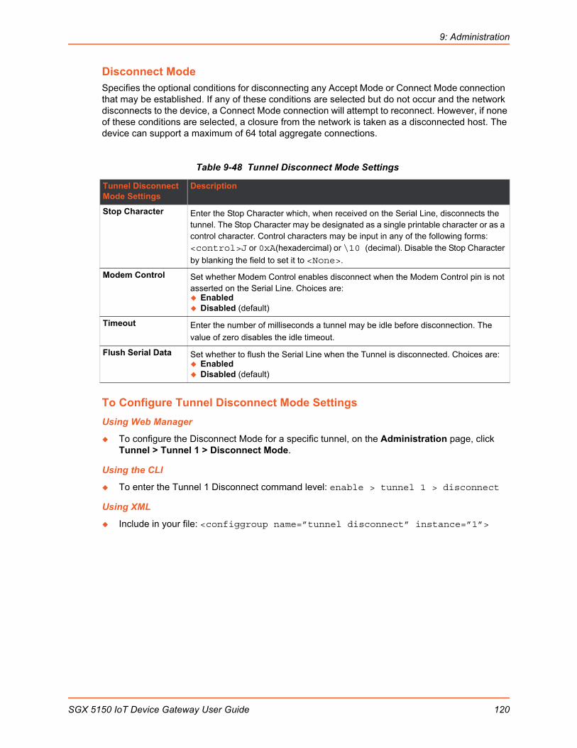
9: Administration
Disconnect ModeSpecifies the optional conditions for disconnecting any Accept Mode or Connect Mode connection that may be established. If any of these conditions are selected but do not occur and the network disconnects to the device, a Connect Mode connection will attempt to reconnect. However, if none of these conditions are selected, a closure from the network is taken as a disconnected host. The device can support a maximum of 64 total aggregate connections.
Table 9-48 Tunnel Disconnect Mode Settings
To Configure Tunnel Disconnect Mode Settings
Using Web Manager
To configure the Disconnect Mode for a specific tunnel, on the Administration page, click Tunnel > Tunnel 1 > Disconnect Mode.
Using the CLI
To enter the Tunnel 1 Disconnect command level: enable > tunnel 1 > disconnect
Using XML
Include in your file: <configgroup name=”tunnel disconnect” instance=”1”>
Tunnel Disconnect Mode Settings
Description
Stop Character Enter the Stop Character which, when received on the Serial Line, disconnects the tunnel. The Stop Character may be designated as a single printable character or as a control character. Control characters may be input in any of the following forms: <control>J or 0xA(hexadercimal) or \10 (decimal). Disable the Stop Character
by blanking the field to set it to <None>.
Modem Control Set whether Modem Control enables disconnect when the Modem Control pin is notasserted on the Serial Line. Choices are: Enabled Disabled (default)
Timeout Enter the number of milliseconds a tunnel may be idle before disconnection. The
value of zero disables the idle timeout.
Flush Serial Data Set whether to flush the Serial Line when the Tunnel is disconnected. Choices are: Enabled Disabled (default)
SGX 5150 IoT Device Gateway User Guide 120
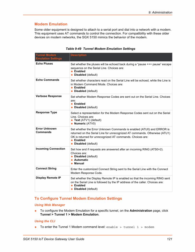
9: Administration
Modem EmulationSome older equipment is designed to attach to a serial port and dial into a network with a modem. This equipment uses AT commands to control the connection. For compatibility with these older devices on modern networks, the SGX 5150 mimics the behavior of the modem.
Table 9-49 Tunnel Modem Emulation Settings
To Configure Tunnel Modem Emulation Settings
Using Web Manager
To configure the Modem Emulation for a specific tunnel, on the Administration page, click Tunnel > Tunnel 1 > Modem Emulation.
Using the CLI
To enter the Tunnel 1 Modem command level: enable > tunnel 1 > modem
Tunnel Modem Emulation Settings
Description
Echo Pluses Set whether the pluses will be echoed back during a “pause +++ pause” escapesequence on the Serial Line. Choices are: Enabled Disabled (default)
Echo Commands Set whether characters read on the Serial Line will be echoed, while the Line is in Modem Command Mode. Choices are: Enabled Disabled (default)
Verbose Response Set whether Modem Response Codes are sent out on the Serial Line. Choices are: Enabled Disabled (default)
Response Type Select a representation for the Modem Response Codes sent out on the Serial Line. Choices are: Text (ATV1) (default) Numeric (ATV0)
Error Unknown Commands
Set whether the Error Unknown Commands is enabled (ATU0) and ERROR is returned on the Serial Line for unrecognized AT commands. Otherwise (ATU1) OK is returned for unrecognized AT commands. Choices are: Enabled Disabled (default)
Incoming Connection Set how and if requests are answered after an incoming RING (ATS0=2). Choices are: Disabled (default) Automatic Manual
Connect String Enter the customized Connect String sent to the Serial Line with the Connect Modem Response Code.
Display Remote IP Set whether the Display Remote IP is enabled so that the incoming RING sent on the Serial Line is followed by the IP address of the caller. Choices are: Enabled Disabled (default)
SGX 5150 IoT Device Gateway User Guide 121
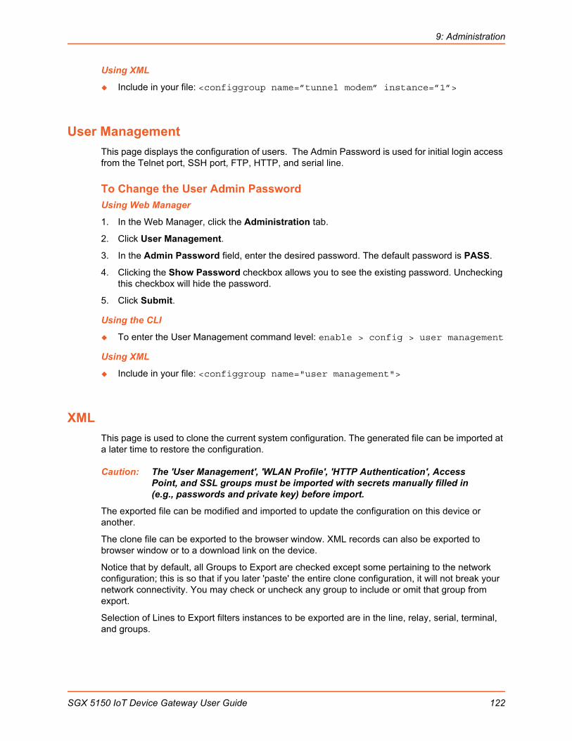
9: Administration
Using XML
Include in your file: <configgroup name=”tunnel modem” instance=”1”>
User Management
This page displays the configuration of users. The Admin Password is used for initial login access from the Telnet port, SSH port, FTP, HTTP, and serial line.
To Change the User Admin PasswordUsing Web Manager
1. In the Web Manager, click the Administration tab.
2. Click User Management.
3. In the Admin Password field, enter the desired password. The default password is PASS.
4. Clicking the Show Password checkbox allows you to see the existing password. Unchecking this checkbox will hide the password.
5. Click Submit.
Using the CLI
To enter the User Management command level: enable > config > user management
Using XML
Include in your file: <configgroup name="user management">
XML
This page is used to clone the current system configuration. The generated file can be imported at a later time to restore the configuration.
Caution: The 'User Management', 'WLAN Profile', 'HTTP Authentication', Access Point, and SSL groups must be imported with secrets manually filled in (e.g., passwords and private key) before import.
The exported file can be modified and imported to update the configuration on this device or another.
The clone file can be exported to the browser window. XML records can also be exported to browser window or to a download link on the device.
Notice that by default, all Groups to Export are checked except some pertaining to the network configuration; this is so that if you later 'paste' the entire clone configuration, it will not break your network connectivity. You may check or uncheck any group to include or omit that group from export.
Selection of Lines to Export filters instances to be exported are in the line, relay, serial, terminal, and groups.
SGX 5150 IoT Device Gateway User Guide 122

9: Administration
To Export ConfigurationBy default, all settings groups are checked.
Using Web Manager
1. In the Web Manager, click the Administration tab.
2. Click XML.
3. Click Export Configuration.
4. Select where to send exported status information:
Export to browser sends the information into a separate web window which appears.
Export to local file sends information into a new locally saved file. A file name must be specified in field provided if this option is selected.
5. Select Download (from link) to download this content as a file, or click Export to browser to open a web browser with this content.
6. To include descriptive comments in the XML file, check Comments.
7. For Lines to Export, check the lines and/or the network that you want to export to the XML configuration file.
Clicking the Clear All button will uncheck all checkboxes.
Clicking the Select All button will check all checkboxes.
8. Click the desired Groups to Export. Several checkboxes are available.
Clicking the Clear All button will uncheck all checkboxes.
Clicking the Select All but Networking button will check all checkboxes except Interface:etho, Bridge:br0 and Interface:wlan0.
Note: Ensure that the group list is comma delimited and encased in double-quotes. To view the list of available groups, type xcr list.
9. Click Export.
Note: Though keys are not exported with XML objects and variables, there is a placeholder value included in the XML variable that would need to be populated with the correct key value when using an exported configuration for an import operation.
Using the CLI
To enter the XML command level: enable > xml
Using XML
Include in your file: <configgroup name="xml">
To Export StatusYou can export the current status in XML format. By default, all groups are exported, or you can select a subset of groups to export.
Using Web Manager
1. In the Web Manager, click the Administration tab.
2. Click XML.
SGX 5150 IoT Device Gateway User Guide 123

9: Administration
3. Click Export Status.
4. Select where to send exported status information:
Export to browser sends the information into a separate web window which appears.
Export to local file sends information into a new locally saved file. A file name must be specified in field provided if this option is selected.
5. For Lines to Export, check the lines and/or the network that you want to export to the XML configuration file.
Clicking the Clear All button will uncheck all checkboxes.
Clicking the Select All button will check all checkboxes.
6. Click the desired Groups to Export. Several checkboxes are available.
Clicking the Clear All button will uncheck all checkboxes.
Clicking the Select All button will check all checkboxes.
Notes:
Ensure that the group list is comma delimited and encased in double-quotes.
To view the list of available groups, type xcr list.
7. Click Export.
Using the CLI
To enter the XML command level: enable > xml
Using XML
Include in your file: <configgroup name="xml">
To Import ConfigurationTo import system XML configuration file that you saved previously, use Import Configuration.
Using Web Manager
1. In the Web Manager, click the Administration tab.
2. Click XML.
3. Click Import Configuration.
4. Select where to import configuration information:
Configuration from External file picks up all the settings from the external file. For this option, click Browse... to locate and select the XML configuration file that you wish to import. The name of the file will appear in the Web Manager screen. Click Import.
Configuration from Filesystem picks up settings from the selected Groups, Lines and Instances. Make selections in form which appears (see Table 9-50) and click Import.
Line(s) from single line Settings on the Filesystem copies lines settings from an the input file containing only one Line instance to all of the selected Lines. Make selections in form which appears (see Table 9-51) and click Import.
Using the CLI
To enter the XML command level: enable > xml
SGX 5150 IoT Device Gateway User Guide 124

9: Administration
Using XML
Include in your file: <configgroup name="xml import control">
Table 9-50 Configuration from Filesystem
Table 9-51 Line(s) from single line Settings on the Filesystem
Quick Setup
Quick Setup provides a place to configure all basic settings in one place. You may access Quick Setup through the Administration menu or whenever you reset your system to factory defaults.
Note: The SGX 5150 IoT Device Gateway Quick Start Guide provides for instructions on accessing Web Manager via SoftAP (go to www.lantronix.com/support/documentation).
Setting Description
Filename Enter the name of the file on the SGX 5150 unit (local to its filesystem) that contains XCR data.
Lines to Import Select filter instances to be imported in the line, serial, tunnel and terminal groups. This affects both Whole Groups to Import and Text List selections. Click Clear All to clear all checkmarks, or Select All to check all checkmarks.
Whole Groups to Import Select the configuration groups to import from the XML configuration record. This option imports all instances of each selected group. Click Clear All to clear all checkmarks, or Select All but Networking to check all checkmarks except Networking.
Text List Enter the string to import specific instances of a group. The textual format of this string is: <g>:<i>;<g>:<i>;...
Each group name <g> is followed by a colon and the instance value <i> and each <g>:<i> value is separated by a semi-colon. If a group has no instance then only the group name <g> should be specified.
Import (button) Click the Import button when the Configuration from Filesystem fields are completed above.
Setting Description
Filename Enter the name of the file on the SGX 5150 unit (local to its filesystem) that contains XCR data.
Lines to Import Select filter instances to be imported in the line, serial, tunnel and terminal groups. This affects both Whole Groups to Import and Text List selections. Click Clear All to clear all checkmarks, or Select All to check all checkmarks.
Whole Groups to Import Select the configuration groups to import from the XML configuration record. This option imports all instances of each selected group. Click Clear All to clear all checkmarks, or Select All but Networking to check all checkmarks except Networking.
Import (button) Click the Import button when the Line(s) from single line Settings on the Filesystem fields are completed above.
SGX 5150 IoT Device Gateway User Guide 125
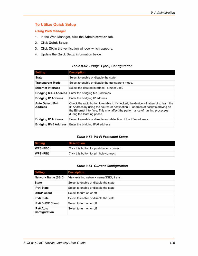
9: Administration
To Utilize Quick Setup
Using Web Manager
1. In the Web Manager, click the Administration tab.
2. Click Quick Setup.
3. Click OK in the verification window which appears.
4. Update the Quick Setup information below:
Table 9-52 Bridge 1 (br0) Configuration
Table 9-53 Wi-Fi Protected Setup
Table 9-54 Current Configuration
Setting Description
State Select to enable or disable the state
Transparent Mode Select to enable or disable the transparent mode.
Ethernet Interface Select the desired interface: eth0 or usb0
Bridging MAC Address Enter the bridging MAC address
Bridging IP Address Enter the bridging IP address
Auto Detect IPv4 Address
Check the radio button to enable it. If checked, the device will attempt to learn the IP Address by using the source or destination IP address of packets arriving on the Ethernet interface. This may affect the performance of running processes during the learning phase.
Bridging IP Address Select to enable or disable autodetection of the IPv4 address.
Bridging IPv6 Address Enter the bridging IPv6 address
Setting Description
WPS (PBC) Click this button for push button connect.
WPS (PIN) Click this button for pin hole connect.
Setting Description
Network Name (SSID) View existing network name/SSID, if any.
State Select to enable or disable the state
IPv4 State Select to enable or disable the state
DHCP Client Select to turn on or off
IPv6 State Select to enable or disable the state
IPv6 DHCP Client Select to turn on or off
IPv6 Auto Configuration
Select to turn on or off
SGX 5150 IoT Device Gateway User Guide 126

9: Administration
Table 9-55 Available Networks
5. Click Clear at any time to clear all fields of choices made (if any). The Clear button will only appear when changes have been made to fields above.
6. Click Manual Setup to return to the Status page where you may make changes directly in the configuration pages accessible through the Network, Diagnostic and Administration tabs.
7. Click Submit to submit configuration choices on the Quick Setup page.
Using the CLI
Not applicable.
Using XML
Not applicable.
Setting Description
Refresh scan results every 60 seconds
Check this checkbox and click Scan to scan available networks every 60 seconds. Scroll through list of available networks listed, as desired.
SGX 5150 IoT Device Gateway User Guide 127

SGX 5150 IoT Device Gateway User Guide 128
A: Lantronix Technical Support
Lantronix offers many resources to support our customers and products at http://www.lantronix.com/support. For instance, you can ask a question, find firmware downloads, access the FTP site and search through tutorials. At this site you can also find FAQs, bulletins, warranty information, extended support services and product documentation.
To contact technical support or sales, look up your local office at http://www.lantronix.com/about/contact.html. When you report a problem, please provide the following information:
Your name, company name, address, and phone number
Lantronix product and model number
Lantronix MAC address or serial number
Firmware version and current configuration
Description of the problem
Status of the unit when the problem occurred (please try to include information on user and network activity at the time of the problem).

B: Compliance
(According to ISO/IEC Guide and EN 45014)
Manufacturer’s Name & Address:
Lantronix, Inc. 7535 Irvine Center Drive, Suite 100, Irvine, CA 92618 USA
Product Name Model:
SGX 5150 IoT Device Gateway
Conforms to the following standards or other normative documents:
Safety
UL 60950-1, 2nd Edition, 2011-12-19 (Information Technology Equipment - Safety - Part 1: General Requirements)
EN 60950-1:2006 + A11:2009 + A1:2010 + A12:2011 + A2:2013
CSA C22.2 No. 60950-1-07, 1st Edition, 2011-12 (Information Technology Equipment - Safety - Part 1: General Requirements)
VCCI
Emissions
CFR Title 47 FCC Part 15, Subpart B, Class B Emissions
EN55022: 2010, Class B Emissions
CISPR 22: 2009, Class B Emissions
VCCI V-3: 2015.04
Immunity
EN55024: 2010
EN610000-4-2: 2009
EN61000-4-3: 2006 + A1: 2008 + A2: 2010
EN61000-4-4: 2004
EN61000-4-5: 2005
EN61000-4-6: 2009
EN61000-4-8: 2010
EN61000-4-11: 2004
CISPR 16-1-4: 2008
ICES-0003 Issue 6
SGX 5150 IoT Device Gateway User Guide 129

B: Compliance
Table B-1 Country Transmitter IDs
Manufacturer’s Contact:
Lantronix, Inc. 7535 Irvine Center DriveSuite 100Irvine, CA 92618 USATel: 949-453-3990Fax: 949-453-3995
RoHS, REACH and WEEE Compliance Statement
Please visit http://www.lantronix.com/legal/rohs/ for Lantronix's statement about RoHS, REACH and WEEE compliance.
Country Specification
USA FCC ID R68PW2050
Canada IC ID 3867A-PW2050
Mexico RCPLAPW15-2109
Japan ID 201-152843
SGX 5150 IoT Device Gateway User Guide 130