515 na operator manual (en) - floor equipment parts · operation 515 mm420 (1-96) 5 operation...
TRANSCRIPT


This manual is furnished with each new TENNANT Model 515. It provides necessary operating andpreventive maintenance instructions. Read this manual completely and understand the machine beforeoperating or servicing it.
This machine will provide excellent service. However, the best results will be obtained at minimum costsif:
D The machine is operated with reasonable care.D The machine is maintained regularly -- per the maintenance instructions provided.D The machine is maintained with TENNANT supplied or equivalent parts.
Manual Number -- MM420
Revision: 09
Published: 6--00
Copyright E 1996, 1997, 1998, 1999, 2000 TENNANT, Printed in U.S.A.

CONTENTS
1515 MM420 (6--00)
CONTENTS
PageSAFETY PRECAUTIONS 3. . . . . . . . . . . . . . . . .OPERATION 5. . . . . . . . . . . . . . . . . . . . . . . . . . . .
OPERATOR RESPONSIBILITY 5. . . . . . . . .MACHINE COMPONENTS 6. . . . . . . . . . . . .SYMBOL DEFINITIONS 7. . . . . . . . . . . . . . . .CONTROLS AND INSTRUMENTS 8. . . . . .
BRAKE PEDAL 9. . . . . . . . . . . . . . . . . . . .DIRECTIONAL PEDAL 9. . . . . . . . . . . . . .STEERING WHEEL 10. . . . . . . . . . . . . . . .SOLUTION LEVER 10. . . . . . . . . . . . . . . . .BATTERY DISCHARGE INDICATOR 11.HOURMETER 11. . . . . . . . . . . . . . . . . . . . .CONTROL PANEL MESSAGE
DISPLAY 12. . . . . . . . . . . . . . . . . . . . . . .CHANGING MESSAGE DISPLAY
LANGUAGE 13. . . . . . . . . . . . . . . . .RECOVERY TANK FULL INDICATOR 13.ESt SWITCH (OPTION) 14. . . . . . . . . . . .EDGE SCRUB SWITCH 14. . . . . . . . . . . . .REAR SQUEEGEE SWITCH 14. . . . . . . .SCRUB SWITCH 15. . . . . . . . . . . . . . . . . . .ON-OFF KEY SWITCH 16. . . . . . . . . . . . . .HORN BUTTON 16. . . . . . . . . . . . . . . . . . . .OPERATING LIGHTS SWITCH
(OPTION) 16. . . . . . . . . . . . . . . . . . . . . .PARKING BRAKE 17. . . . . . . . . . . . . . . . . .POWER WAND SWITCH (OPTION) 17. .CIRCUIT BREAKERS 18. . . . . . . . . . . . . . .SOLUTION TANK DRAIN HOSE 19. . . . .RECOVERY TANK DRAIN HOSE 19. . . .POSITIVE SOLUTION CONTROL
DRAIN (OPTION) 19. . . . . . . . . . . . . . . .OPERATOR SEAT 19. . . . . . . . . . . . . . . . . .
HOW THE MACHINE WORKS 20. . . . . . . . . .PRE-OPERATION CHECKLIST 21. . . . . . . . .STARTING THE MACHINE 22. . . . . . . . . . . . .FILLING THE TANKS 22. . . . . . . . . . . . . . . . . .SCRUBBING AND BRUSH
INFORMATION 25. . . . . . . . . . . . . . . . . . . .SCRUBBING 26. . . . . . . . . . . . . . . . . . . . . . . . .DOUBLE SCRUBBING 28. . . . . . . . . . . . . . . . .
LOCKING UP SIDE SQUEEGEES 28. . . .UNLOCKING SIDE SQUEEGEES 29. . . .
STOP SCRUBBING 30. . . . . . . . . . . . . . . . . . .DRAINING AND CLEANING THE
TANKS 31.STOP THE MACHINE 34. . . . . . . . . . . . . . . . .POST-OPERATION CHECKLIST 35. . . . . . . .OPERATION ON INCLINES 36. . . . . . . . . . . .OPTIONS 37. . . . . . . . . . . . . . . . . . . . . . . . . . . .
VACUUM WAND 37. . . . . . . . . . . . . . . . . . .POWER WAND 41. . . . . . . . . . . . . . . . . . . .
MACHINE TROUBLESHOOTING 46. . . . . . .
PageMAINTENANCE 48. . . . . . . . . . . . . . . . . . . . . . . . .
MAINTENANCE CHART 48. . . . . . . . . . . . . . .LUBRICATION 50. . . . . . . . . . . . . . . . . . . . . . . .
PROPELLING GEARBOX 50. . . . . . . . . . .FRONT WHEEL SUPPORT
BEARING 50. . . . . . . . . . . . . . . . . . . . . .STEERING UNIVERSAL JOINT 50. . . . . .SCRUB HEAD PARALLEL ARMS 51. . . .REAR SQUEEGEE CASTER 52. . . . . . . .STEERING GEAR CHAIN 52. . . . . . . . . . .
BATTERIES 53. . . . . . . . . . . . . . . . . . . . . . . . . .CHARGING THE BATTERIES 54. . . . . . .
CONTROL PANEL 56. . . . . . . . . . . . . . . . . . . .ELECTRIC MOTORS 57. . . . . . . . . . . . . . . . . .PROPELLING CIRCUIT 57. . . . . . . . . . . . . . . .SCRUB HEAD 57. . . . . . . . . . . . . . . . . . . . . . . .
SCRUB HEAD FLOOR SKIRTS 58. . . . . .SCRUB HEAD GAS SPRING 58. . . . . . . .SCRUB HEAD ADJUSTMENTS 58. . . . . .
SCRUB BRUSHES 58. . . . . . . . . . . . . . . . . . . .REPLACING THE SCRUB BRUSHES 59
SOLUTION SYSTEM 60. . . . . . . . . . . . . . . . . .SOLUTION VALVE 60. . . . . . . . . . . . . . . . .RECOVERY TANK 60. . . . . . . . . . . . . . . . .SOLUTION TANK 61. . . . . . . . . . . . . . . . . .
SQUEEGEES 62. . . . . . . . . . . . . . . . . . . . . . . . .REAR SQUEEGEE 62. . . . . . . . . . . . . . . . .
LEVELING THE REARSQUEEGEE 62. . . . . . . . . . . . . . . . .
ADJUSTING REAR SQUEEGEEBLADE DEFLECTION 64. . . . . . . . .
SIDE SQUEEGEE ADJUSTMENT 65. . . .SQUEEGEE BLADES 65. . . . . . . . . . . . . . . . .
REAR SQUEEGEE BLADES 65. . . . . . . . .REPLACING OR ROTATING THE
REAR SQUEEGEE BLADES 65. . .SIDE SQUEEGEES BLADES 66. . . . . . . .
REPLACING SIDE SQUEEGEEBLADES 67. . . . . . . . . . . . . . . . . . . . .
CHAINS 68. . . . . . . . . . . . . . . . . . . . . . . . . . . . . .STEERING GEAR CHAIN 68. . . . . . . . . . .STATIC DRAG CHAIN 68. . . . . . . . . . . . . .
BRAKES AND TIRES 69. . . . . . . . . . . . . . . . . .BRAKES 69. . . . . . . . . . . . . . . . . . . . . . . . . .TIRES 69. . . . . . . . . . . . . . . . . . . . . . . . . . . .FRONT WHEEL 69. . . . . . . . . . . . . . . . . . . .
PUSHING, TOWING, ANDTRANSPORTING THE MACHINE 70. . . .PUSHING OR TOWING THE
MACHINE 70. . . . . . . . . . . . . . . . . . . . . .TRANSPORTING THE MACHINE 71. . . .
MACHINE JACKING 73. . . . . . . . . . . . . . . . . . .STORAGE INFORMATION 74. . . . . . . . . . . . .

CONTENTS
515 MM420 (6--00)2
PageSPECIFICATIONS 75. . . . . . . . . . . . . . . . . . . . . . .
GENERAL MACHINE PERFORMANCE 75. .POWER TYPE 76. . . . . . . . . . . . . . . . . . . . . . . .STEERING 76. . . . . . . . . . . . . . . . . . . . . . . . . . .BRAKING SYSTEM 76. . . . . . . . . . . . . . . . . . .TIRES 76. . . . . . . . . . . . . . . . . . . . . . . . . . . . . . .MACHINE DIMENSIONS 77. . . . . . . . . . . . . . .
INDEX 78. . . . . . . . . . . . . . . . . . . . . . . . . . . . . . . . . .

SAFETY PRECAUTIONS
3515 MM420 (6--00)
SAFETY PRECAUTIONS
The following symbols are used throughout thismanual as indicated in their description:
WARNING: To warn of hazards orunsafe practices that could result insevere personal injury or death.
FOR SAFETY: To identify actions thatmust be followed for safe operation ofequipment.
The following information signals potentiallydangerous conditions to the operator orequipment. Read this manual carefully. Knowwhen these conditions can exist. Locate all safetydevices on the machine. Then, take necessarysteps to train machine operating personnel.Report machine damage or faulty operationimmediately. Do not use the machine if it is not inproper operating condition.
FOR SAFETY:
1. Do not operate machine:-- Unless trained and authorized.-- Unless operation manual is read and
understood.-- In flammable or explosive areas unless
designed for use in those areas.-- In areas with possible falling objects
unless equipped with overhead guard.
2. Before starting machine:-- Make sure all safety devices are in
place and operate properly.-- Check brakes and steering for proper
operation.
3. When starting machine:-- Keep foot on brake and directional
pedal in neutral.
4. When using machine:-- Use brakes to stop machine.-- Go slow on inclines and slippery
surfaces.-- Use care when backing machine.-- Do not carry riders on machine.-- Always follow safety and traffic rules.-- Report machine damage or faulty
operation immediately.-- Follow mixing and handling
instructions on chemical containers.
5. Before leaving or servicing machine:-- Stop on level surface.-- Set parking brake.-- Turn off machine and remove key.
6. When servicing machine:-- Avoid moving parts. Do not wear loose
jackets, shirts, or sleeves whenworking on machine.
-- Block machine tires before jackingmachine up.
-- Jack machine up at designatedlocations only. Block machine up withjack stands.
-- Use hoist or jack of adequate capacityto lift machine.
-- Wear eye and ear protection whenusing pressurized air or water.
-- Disconnect battery connections beforeworking on machine.
-- Avoid contact with battery acid.-- Use Tennant supplied or equivalent
replacement parts.
7. When loading/unloading machineonto/off truck or trailer:-- Turn off machine.-- Use winch. Do not drive the machine
onto/off the truck or trailer unless theload height is 380 mm (15 in) or lessfrom the ground.
-- Set parking brake after machine isloaded.
-- Block machine tires.-- Tie machine down to truck or trailer.
WARNING: Batteries emit hydrogen gas.Explosion or fire can result. Keepsparks and open flame away. Keepcovers open when charging.
WARNING: Flammable materials cancause an explosion or fire. Do not useflammable materials in tank(s).
WARNING: Flammable materials orreactive metals can cause an explosionor fire. Do not pickup.
SAFETY PRECAUTIONS
515 MM420 (10--96)4
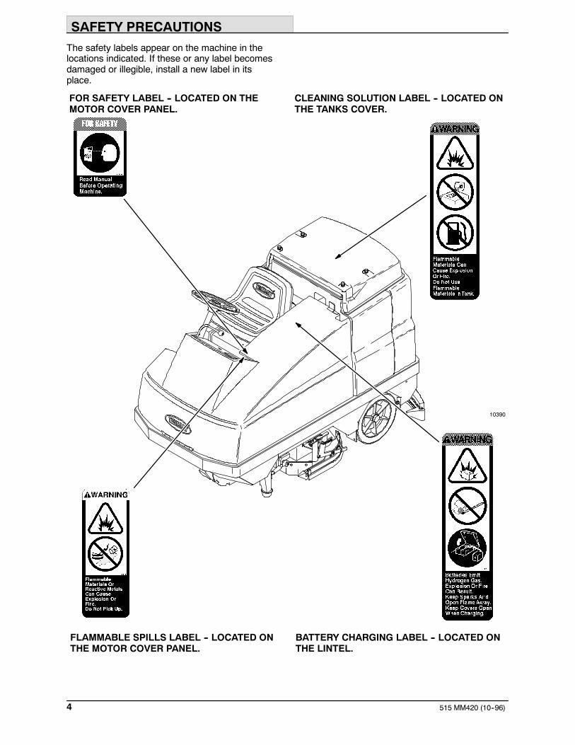
The safety labels appear on the machine in thelocations indicated. If these or any label becomesdamaged or illegible, install a new label in itsplace.
10390
CLEANING SOLUTION LABEL -- LOCATED ONTHE TANKS COVER.
BATTERY CHARGING LABEL -- LOCATED ONTHE LINTEL.
FOR SAFETY LABEL -- LOCATED ON THEMOTOR COVER PANEL.
FLAMMABLE SPILLS LABEL -- LOCATED ONTHE MOTOR COVER PANEL.

OPERATION
5515 MM420 (1--96)
OPERATION
OPERATOR RESPONSIBILITY
- The operator’s responsibility is to take careof the daily maintenance and checkups ofthe machine to keep it in good workingcondition. The operator must inform theservice mechanic or supervisor when themaintenance intervals are required as statedin the MAINTENANCE section of thismanual.
- Read this manual carefully before operatingthis machine.
FOR SAFETY: Do not operate machine,unless operation manual is read andunderstood.
- Check the machine for shipping damage.Check to make sure the machine iscomplete per shipping instructions.
- Keep your machine regularly maintained byfollowing the maintenance information in thismanual. We recommend taking advantageof a regularly scheduled service contractfrom your Tennant representative.
- Order parts and supplies directly from yourauthorized Tennant representative. Use theparts manual provided when ordering parts.
- After the first 50 hours of operation, followthe recommended procedures stated in theMAINTENANCE CHART.
07324

OPERATION
515 MM420 (12--96)6
MACHINE COMPONENTS
AB
D
E
F
G
J
I
K
L
H
CD
E
F
C
K
1064110390
A. Operator seatB. Steering wheelC. Machine coverD. Recovery tankE. Solution tankF. Tank coverG. Rear squeegeeH. Side squeegeeI. Solution tank drainJ. Recovery tank drainK. Rear wheelL. Seat support

OPERATION
7515 MM420 (1--96)
SYMBOL DEFINITIONS
These symbols identify controls, displays, andfeatures on the machine:
Battery charging system Headlights
Hour meter Solution flow
Recovery tank full Circuit breaker #1
ESt Circuit breaker #2
Scrub brush edge clean Circuit breaker #3
Squeegee down Circuit breaker #4
Down pressure Circuit breaker #5
Scrub brush down and on Circuit breaker #6
Horn Circuit breaker #7
Key switch Circuit breaker #8
Jack-point

OPERATION
515 MM420 (9--98)8
CONTROLS AND INSTRUMENTS
B
C
D
E F G
H
IJ K
L
M
NO
P
A
10639
A. Brake pedalB. Directional pedalC. Steering wheelD. Solution leverE. Battery discharge indicatorF. Hour meterG. Recovery tank full indicatorH. ESt switch (Option)I. Edge scrub switchJ. Rear squeegee switchK. Scrub switchL. On-off key switchM. Horn buttonN. Operating lights switch/revolving light switchO. Parking brakeP. Power wand switch (Option)

OPERATION
9515 MM420 (1--96)
BRAKE PEDAL
The brake pedal stops the machine.
Stop: Take your foot off the directional pedal andlet it return to the neutral position. Step on thebrake pedal.
DIRECTIONAL PEDAL
The directional pedal controls direction of traveland the propelling speed of the machine. Youchange the speed of the machine with thepressure of your foot; the harder you press thefaster the machine travels.
The machine will coast for a short distance beforechanging direction when it is moving, and thedirection is reversed with the directional pedal.Use the brake pedal to stop the machine.
Forward: Press the top of the directional pedalwith the toe of your foot.
Reverse: Press the bottom of the directionalpedal with the heel of your foot.
OPERATION
515 MM420 (1--96)10
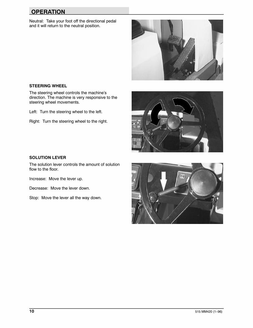
Neutral: Take your foot off the directional pedaland it will return to the neutral position.
STEERING WHEEL
The steering wheel controls the machine’sdirection. The machine is very responsive to thesteering wheel movements.
Left: Turn the steering wheel to the left.
Right: Turn the steering wheel to the right.
SOLUTION LEVER
The solution lever controls the amount of solutionflow to the floor.
Increase: Move the lever up.
Decrease: Move the lever down.
Stop: Move the lever all the way down.

OPERATION
11515 MM420 (1--96)
BATTERY DISCHARGE INDICATOR
The battery discharge indicator shows the chargelevel of the batteries with a segmented display.
When the batteries are fully charged, all thesegments are lit. As the batteries discharge, thesegments shut off.
The batteries should be recharged when all thesegments have shut off. At this point, thescrubbing functions will automatically shut off toalert the operator of the battery condition. Thesqueegee and vacuum can be operated, with therear squeegee switch, for an additional 30seconds to pick up any excess water.
NOTE: Do not charge the batteries more oftenthan is necessary to prolong the life of thebatteries. Do not charge the batteries with a “topoff” charge if there is enough remaining charge inthe batteries for the next machine use. Dischargethe batteries to a 20% level, when the batterydischarge indicator segments shut off, before fullycharging the batteries. Do not allow the batteriesto become completely discharged as this will alsodamage the batteries. See BATTERIES in theMAINTENANCE section.
HOURMETER
The hourmeter records the number of hours themachine has been operating. This information isuseful when maintaining the machine.
10658
10659

OPERATION
515 MM420 (1--96)12
CONTROL PANEL MESSAGE DISPLAY
The hour meter and battery discharge indicatordisplay also logs and displays messages to theoperator. When a scheduled maintenance intervalhas passed, the control panel will internally log theevent and display a message the next time themachine is powered on. See the chart below forthe normal operating messages. If any messagesappear other than those listed in the chart, contactyour service personnel.
Message Description
Tanks Full The auto-fill has turned off. Thetanks are filled to the properlevel.
Rec. Tank Full Recovery tank is full.
XX hour check Check the Maintenance Chartfor the scheduled maintenanceat the number of hours stated inthe message.
XX hour lube Check the Maintenance Chartfor the scheduled maintenanceat the number of hours stated inthe message.
Breaker CB3 Brush circuit breaker hastripped for the right brush motor.The circuit breaker must bereset before resumingscrubbing.
Breaker CB4 Brush circuit breaker hastripped for the left brush motor.The circuit breaker must bereset before resumingscrubbing.
Breaker CB5 Brush circuit breaker hastripped for the center brushmotor (MaxProt 1200 option).The circuit breaker must bereset before resumingscrubbing.
To remove the message from the hour meter andbattery discharge indicator display, turn themachine power off and then back on again.
The message display language can be changed.The available languages are:
English SwedishDutch DanishItalian NorwegianSpanish FinnishFrench PortugueseGerman Japanese
10660

OPERATION
13515 MM420 (3--98)
CHANGING MESSAGE DISPLAY LANGUAGE
1. With the machine powered off, press andhold the scrub and edge scrub switches.
2. Turn the machine power on.
3. Continue pressing the scrub and edge scrubswitches for 5 more seconds.
4. Release the scrub and edge scrub switches.
5. Press the ESt switch to scroll through thelist of languages until the desired languageis displayed.
6. Turn the machine power off, and the newlanguage will be stored in the control panel.
RECOVERY TANK FULL INDICATOR
The recovery tank full indicator comes on whenthe recovery tank is full.
If the recovery tank full indicator stays on for morethan 7 seconds, the “Rec. Tank Full” message willappear in the hourmeter display. The scrubbrushes and vacuum will shut off, and the rearsqueegee will raise.
To pick up excess water after the vacuum hasshut off and the rear squeegee has raised, pressand hold the rear squeegee switch.
Note: Do not overfill the recovery tank. Overfillingthe recovery tank may damage the vacuum fans.
10734
10662
10661

OPERATION
515 MM420 (1--96)14
ESt SWITCH (OPTION)
The ESt switch turns on and off the solutionrecycling system.
On: Press the switch. The indicator will light.
Off: Press the switch.
EDGE SCRUB SWITCH
The edge scrub switch extends the scrub head tothe right to allow close edge scrubbing.
On: Press the switch during normal scrubbing.The indicator will light.
Off: Press the switch again.
REAR SQUEEGEE SWITCH
The rear squeegee switch, along with the directionof travel, controls the rear squeegee position andscrubbing vacuum fan.
Lower squeegee and start vacuum: Press theswitch. The indicator will light.
Raise squeegee and stop vacuum: Press theswitch.
The rear squeegee lifts when the machine travelsin reverse. This prevents the rear squeegee frombeing damaged when reversing the machine. Therear squeegee will lower again when the machinetravels forward.
10662
10663
10880

OPERATION
15515 MM420 (1--96)
SCRUB SWITCH
The scrub switch controls the scrubbingoperations. The scrub switch also sets the scrubbrush pressure.
The scrubbing operations include the following.The scrub head lowers and the brushes turn on.The rear squeegee will lower and the vacuum willstart. Also, the optional ESt system will start.
Start scrubbing: Press the switch. The indicatorswill light to the preset brush pressure. Thescrubbing system will start when the machinemoves forward.
NOTE: The brush pressure setting, the edgescrub, and the ESt system will default to the lastsetting used when the scrubbing operations arestarted again.
Stop scrubbing: Press the switch. The indicatorswill go off. First the scrub brushes will stop andraise, then the rear squeegee will raise and thevacuum will shut off.
Scrub brush pressure: Press and hold the scrubswitch. The brush pressure will scroll through thefour settings. Whatever pressure setting isselected when the switch is released, will be thenew default brush pressure setting.
The brush pressure has four positions. Undernormal conditions, the brush pressure should beset in the minimum settings. Under heavy grimeconditions, the brush pressure should be set inthe maximum settings. Travel speed and floorconditions will affect the scrubbing performance.
NOTE: The rear squeegee will raise and thevacuum will shut off when the machine travels inreverse. The squeegee will lower and the vacuumstarts again when the machine travels forward.
NOTE: The scrub brushes will stop when themachine is stopped for a short time. The brusheswill start again when the machine travels forward.
10881

OPERATION
515 MM420 (1--96)16
ON-OFF KEY SWITCH
The on-off key switch controls machine powerwith a key.
On: Turn the key clockwise all the way.
Off: Turn the key counter-clockwise.
HORN BUTTON
The horn button operates the horn.
Sound: Press the button.
OPERATING LIGHTS SWITCH (OPTION)
The operating lights switch powers on and off theheadlights, taillights, and hazard light option.
On: Press the top of the switch.
Off: Press the bottom of the switch.
10906

OPERATION
17515 MM420 (1--96)
PARKING BRAKE
The parking brake lever sets and releases therear wheel brakes.
Set: Pull the parking brake lever up.
FOR SAFETY: Before leaving or servicingmachine; stop on level surface, set parkingbrake, turn off machine and remove key.
Release: Push the parking brake lever down.
POWER WAND SWITCH (OPTION)
The power wand switch turns on and off thepower wand solution system.
On: Press the top of the switch. The switch willlight up.
Off: Press the bottom of the switch.

OPERATION
515 MM420 (1--96)18
CIRCUIT BREAKERS
The circuit breakers are resetable electrical circuitprotection devices. They stop the flow of currentin the event of a circuit overload. Once a circuitbreaker is tripped, reset it manually by pressingthe reset button after the breaker has cooleddown.
If the overload that caused the circuit breaker totrip is still there, the circuit breaker will continue tostop current flow until the problem is corrected.
The fuse is a one-time circuit protection devicedesigned to stop the flow of current in the event ofa circuit overload. Never substitute higher valuefuses than those specified in this manual.
The circuit breakers are located to the left of theoperator’s compartment near the machine andbattery connectors and on the control boxes. Thefuses are located in the main control box.
The chart shows the circuit breakers and fuses,and the electrical components they protect.
CircuitBreaker Rating Circuit Protected
CB1 20 A Scrubbing vacuum fan motor
CB2 20 A Scrubbing vacuum fan motor
CB3 40 A Right scrub brush motor
CB3 50 A Heavy duty right scrub brush motor(option)
CB4 40 A Left scrub brush motor
CB4 50 A Heavy duty left scrub brush motor(option)
CB5 40 A Center scrub brush motor (option)
CB6 2.5 A Control Circuit
CB7 15 A Control panel
CB8 15 A Horn, hazard and operating lights(option)

OPERATION
19515 MM420 (12--96)
SOLUTION TANK DRAIN HOSE
The solution tank drain hose is used to drain thesolution tank. Drain the solution tank by removingthe drain hose cap from the tank access cap. Pullout the solution tank hose and remove the drainhose end cap.
RECOVERY TANK DRAIN HOSE
The recovery tank drain hose is used to drain therecovery tank. Drain the recovery tank byremoving the drain hose cap from the tank accesscap. Pull out the recovery tank hose and removethe drain hose end cap.
POSITIVE SOLUTION CONTROL DRAIN(OPTION)
For machines with the positive solution controldrain option, remove the dust cap. Connect thedrain hose to the solution control drain and openthe drain valve.
OPERATOR SEAT
The operator set is a fixed back style with aforward-backward adjustment.
Adjust: Remove the seat mounting bolts, movethe seat to the desired position; reinstall andtighten the bolts.

OPERATION
515 MM420 (1--96)20
HOW THE MACHINE WORKS
The steering wheel controls the direction ofmachine travel. The directional pedal controls thespeed and forward/reverse directions. The brakepedal slows and stops the machine.
The scrub components of the machine are asolution tank, scrub brushes, rear and sidesqueegees, a vacuum system, and a recoverytank.
Water and detergent, from the solution tank, flowto the floor through a solution valve to the scrubbrushes. The brushes scrub the floor. As themachine is moved forward the squeegees wipethe dirty solution off the floor, which is then pickedup and drawn into the recovery tank.
When using the ESt mode, the solution in therecovery tank is filtered and returned to thesolution tank to be reused.
Two different widths of scrub heads are availablefor the machine. The MaxProt 1000 scrub headcontains two disk scrub brushes. The MaxProt1200 scrub head contains three disk scrubbrushes.
When finished scrubbing, drain and clean therecovery tank. If using the ESt system, drain andclean the solution tank, and clean the ESt filter.

OPERATION
21515 MM420 (1--96)
PRE-OPERATION CHECKLIST
Check over this list of items before operating themachine:
- Check under the machine for leaks.
- Check the brakes and steering for properoperation.
- Check the squeegee for proper deflection.Check the squeegee blade for wear,rounded edges, nicks, or cuts.
OPERATION
515 MM420 (4--97)22
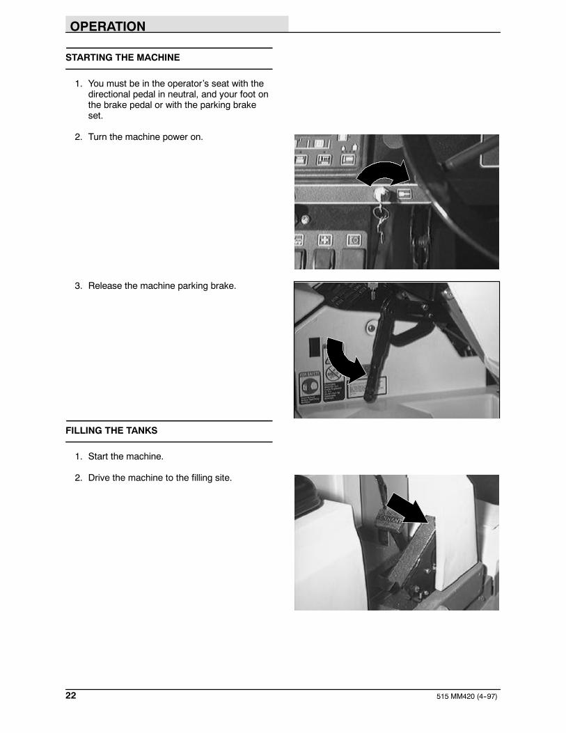
STARTING THE MACHINE
1. You must be in the operator’s seat with thedirectional pedal in neutral, and your foot onthe brake pedal or with the parking brakeset.
2. Turn the machine power on.
3. Release the machine parking brake.
FILLING THE TANKS
1. Start the machine.
2. Drive the machine to the filling site.

OPERATION
23515 MM420 (6--00)
3. Turn the machine power off.
FOR SAFETY: Before leaving orservicing machine; stop on levelsurface, set parking brake, turn offmachine and remove key.
4. Set the parking brake.
5. Open the tank cover and pour the requiredamount of detergent into the solution tank fillopening. Fill the solution tank with water to75 mm (3 in) below the tank opening.
If you do not want to use the ESt system, makesure the ESt system is off. DO NOT fill therecovery tank.
NOTE: If you are going to scrub in the EStmode, the recovery tank can be partially filled toextend scrub time. Make sure the ESt system ison.
FOR SAFETY: Follow mixing andhandling instructions on chemicalcontainers.
05921

OPERATION
515 MM420 (1--96)24
6. ESt mode: Connect the hose and adaptorfrom the water source to the auto-fillconnection on the machine.
NOTE: When using the auto-fill feature on theESt machine, both tanks should be empty toprevent overfilling of the tanks.
Turn the machine power on, and turn on thewater source. The auto-fill will automaticallyfill the tanks to the proper level for EStoperation. When the auto-fill stops, themessage “Tanks Full” will appear on thehourmeter display.
The tanks can also be filled manually. Fill thesolution tank with water to 75 mm (3 in)below the tank opening. Fill the recoverytank half full.
NOTE: Floor conditions, water condition, amountof soilage, types of soilage, and brush action allplay an important role in determining the type andconcentration of detergent used. For specificrecommendations, contact your Tennantrepresentative.
WARNING: Flammable materials cancause an explosion or fire. Do not useflammable materials in tank(s).
7. Close the tank cover.
05922
05921

OPERATION
25515 MM420 (1--96)
SCRUBBING AND BRUSH INFORMATION
Pick up oversized debris before scrubbing. Pickup pieces of wire, string, twine, etc., which couldbecome wrapped around the scrubbing brushes.
Plan the scrubbing in advance. Try to arrangelong runs with minimum stopping and starting. Doan entire floor or section at one time.
Drive as straight a path as possible. Avoidbumping into posts or scraping the sides of themachine. Overlap the scrub paths by severalcentimeters (a few inches).
Avoid turning the steering wheel too sharply whenthe machine is in motion. The machine is veryresponsive to the movement of the steeringwheel. Avoid sudden turns, except inemergencies.
When scrubbing dead end aisles, start at theclosed end of the aisle and scrub your way out.
Adjust the machine speed, scrub brush pressure,and solution flow as required when scrubbing.Use minimum scrub brush pressure and solutionflow required for the best results. The machinehas an edge clean feature for scrubbing againstan edge.
If you see poor scrubbing performance, stopscrubbing and refer to MACHINETROUBLESHOOTING.
For best results, use the correct brush type foryour cleaning application. The following arerecommended brush applications.
Non-scuff polypropylene scrub brush -- Thisbrush uses a softer, general purposepolypropylene bristle to lift lightly compactedsoilage without scuffing high-gloss coated floors.
Nylon scrub brush -- Recommended forscrubbing coated floors. Cleans without scuffing.
Super abrasive bristle scrub brush -- Nylonfiber impregnated with abrasive grit to removestains and soilage. Strong action on any surface,performing well on buildup, grease, or tire marks.
Stripping pad -- This brown pad is for strippingfloors. Quickly and easily cuts through old finish toprepare the floor for re-coating.
05939

OPERATION
515 MM420 (1--96)26
Scrubbing pad -- This blue pad is for scrubbingfloors. Removes dirt, spills and scuffs, leaving aclean surface ready for re-coating.
Buffing pad -- This red pad is for buffing floors.Quickly cleans and removes scuff marks whilepolishing the floor to a high gloss.
Polishing pad -- This white pad is for polishingfloors. Maintains a high gloss. Use for buffing verysoft finishes and lower traffic areas, or use forpolishing soft waxes on wood floors.
SCRUBBING
1. Start the machine.
2. Drive the machine to the area to be cleaned.
3. Press the scrub switch.
When the machine travels forward, the rearsqueegee will lower, the scrubbing vacuumwill start, the scrub head will lower, and thescrub brushes will start.
4. Move the solution lever up to start thesolution flow.
10884

OPERATION
27515 MM420 (6--00)
5. To scrub close to edges with the MaxProt1000, press the edge scrub switch.
6. Drive the machine forward and scrub asrequired.
WARNING: Flammable materials orreactive metals can cause an explosionor fire. Do not pickup.
7. Adjust the solution flow to the floor asneeded.
NOTE: When approaching a corner, reduce thesolution flow just before turning the corner.Increase the solution flow once the machine hascompleted the turn.
8. Adjust the brush pressure for the cleaningapplication.
10883
10884

OPERATION
515 MM420 (1--96)28
DOUBLE SCRUBBING
Double scrubbing is a method for removing heavyfloor accumulations. This is done by making twoor more passes over the area to be cleaned withthe machine.
First, make a pass over the area scrubbing withthe side and rear squeegees up. This dispensessolution over the area allowing the solution tosoak on the floor. Let the solution remain on thefloor for 15 to 20 minutes. Then make a secondpass scrubbing with the squeegees down.
Lock the side squeegees up during doublescrubbing.
FOR SAFETY: When using machine, goslow on inclines and slippery surfaces.
LOCKING UP SIDE SQUEEGEES
1. Turn the machine power off.
FOR SAFETY: Before leaving orservicing machine; stop on levelsurface, set parking brake, turn offmachine and remove key.
2. Set the parking brake.
3. Lift the left side squeegee up.

OPERATION
29515 MM420 (4--96)
4. Turn the squeegee stop towards the front ofthe machine and hold in place.
5. Lower the side squeegee against the stop.
6. Repeat the steps with the right sidesqueegee for the MaxProt 1000 scrubhead. For the MaxProt 1200 scrub head,disconnect the lift chain from the machineframe. Lift up the right side of the scrubhead and connect the lift chain to the bottomof the side bracket.
UNLOCKING SIDE SQUEEGEES
1. Turn the machine power off.
FOR SAFETY: Before leaving orservicing machine; stop on levelsurface, set parking brake, turn offmachine and remove key.
2. Set the parking brake.
3. Lift the left side squeegee. The stop willmove out of the way.
4. Lower the side squeegee to the floor.
5. Repeat the steps with the right sidesqueegee on the MaxProt 1000 scrubhead. For the MaxProt 1200 scrub head,lift up the right side of the scrub head anddisconnect the lift chain from the bottom ofthe side bracket. Lower the scrub head.Connect the lift chain to the main frame.
05927

OPERATION
515 MM420 (1--96)30
STOP SCRUBBING
1. Move the solution flow lever all the waydown to stop solution flow to the floor.
ESt mode: Press the ESt switch to turnoff the ESt system.
2. Press the scrub switch.
The scrub head will raise, the scrub brushmotors will stop, the rear squeegee will raiseafter a short delay, and the vacuum will shutoff.
10884
OPERATION
31515 MM420 (1--96)
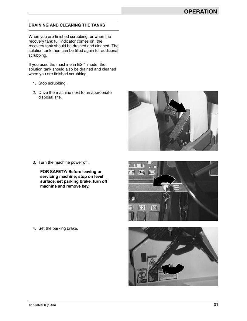
DRAINING AND CLEANING THE TANKS
When you are finished scrubbing, or when therecovery tank full indicator comes on, therecovery tank should be drained and cleaned. Thesolution tank then can be filled again for additionalscrubbing.
If you used the machine in ESt mode, thesolution tank should also be drained and cleanedwhen you are finished scrubbing.
1. Stop scrubbing.
2. Drive the machine next to an appropriatedisposal site.
3. Turn the machine power off.
FOR SAFETY: Before leaving orservicing machine; stop on levelsurface, set parking brake, turn offmachine and remove key.
4. Set the parking brake.
OPERATION
515 MM420 (3--98)32
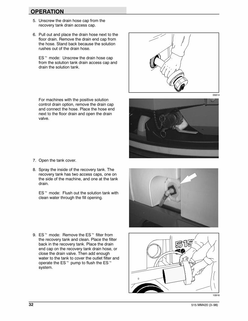
5. Unscrew the drain hose cap from therecovery tank drain access cap.
6. Pull out and place the drain hose next to thefloor drain. Remove the drain end cap fromthe hose. Stand back because the solutionrushes out of the drain hose.
ESt mode: Unscrew the drain hose capfrom the solution tank drain access cap anddrain the solution tank.
For machines with the positive solutioncontrol drain option, remove the drain capand connect the hose. Place the hose endnext to the floor drain and open the drainvalve.
7. Open the tank cover.
8. Spray the inside of the recovery tank. Therecovery tank has two access caps, one onthe side of the machine, and one at the tankdrain.
ESt mode: Flush out the solution tank withclean water through the fill opening.
9. ESt mode: Remove the ESt filter fromthe recovery tank and clean. Place the filterback in the recovery tank. Place the drainend cap on the recovery tank drain hose, orclose the drain valve. Then add enoughwater to the tank to cover the outlet filter andoperate the ESt pump to flush the EStsystem.
05914
10916

OPERATION
33515 MM420 (9--98)
10. Remove the vacuum inlet screen from thetank cover and clean. Place the inlet filterback in the tank cover.
11. For machines serial number 004868and above, open the machine cover to gainaccess to the vacuum fan filter. Remove theknobs and the vacuum filter cover.
Remove and clean the vacuum fan filter byshaking the dust, using low pressure air, orrinsing pleats with low pressure water.
NOTE: Be sure the vacuum fan filter is dry beforereinstalling it in the machine.
Insert the filter and place the cover back intothe machine. Close the machine cover.
12. Place the drain end caps on the tank drainhoses. Push the drain hoses back into thetanks.
For machines with the positive solutioncontrol drain option, close the drain valve.Remove the hose and connect the draincap.
05921

OPERATION
515 MM420 (9--98)34
STOP THE MACHINE
1. Stop scrubbing.
2. Turn the machine power off.
3. Set the parking brake.
FOR SAFETY: Before leaving orservicing machine; stop on levelsurface, set parking brake, turn offmachine and remove key.

OPERATION
35515 MM420 (1--96)
POST-OPERATION CHECKLIST
Check over this list of items after you havefinished scrubbing with the machine powered on:
- Check the battery charge level.
NOTE: The reading on the battery dischargeindicator is not accurate when the machine is firstpowered on. Operate the machine a few minutesbefore reading the charge level of the batteries.
Check over this list of items with the machinepowered off:
- Check for wire, string, or twine wrappedaround the brushes.
- Check the squeegees for wear or damage.
10658

OPERATION
515 MM420 (3--98)36
- Drain and clean the recovery tank.
- ESt machines: Drain and clean thesolution tank. Clean the ESt filter. Thenadd enough water to the tank to cover theoutlet filter and operate the ESt pump toflush the ESt system.
- Check the vacuum hoses for obstructions.
- Check for any machine leaks.
- Check the service records to determineservice requirements.
OPERATION ON INCLINES
Drive the machine slowly on inclines.
FOR SAFETY: When using machine, goslow on inclines and slippery surfaces.
The maximum rated climb and descent inclinewith empty tanks is 8.5_, and with full tanks is5.7_.
10916

OPERATION
37515 MM420 (6--00)
OPTIONS
VACUUM WAND
The vacuum wand uses the machine’s vacuumsystem. The vacuum wand and hose allowspick-up of spills that are out of reach of themachine.
WARNING: Flammable materials orreactive metals can cause an explosionor fire. Do not pickup.
1. Turn the machine power off.
FOR SAFETY: Before leaving orservicing machine; stop on levelsurface, turn off machine.
2. Set the parking brake.

OPERATION
515 MM420 (4--97)38
3. Remove the vacuum wand equipment fromthe tank cover.
4. Remove the squeegee suction hose fromthe top of the rear squeegee.
5. Connect the vacuum wand hose and thesqueegee suction hose and secure with theretainer clip.
6. Put together the wand and the wand hose.
7. Turn the machine power on.
05929
05930
10945

OPERATION
39515 MM420 (4--97)
8. Press the rear squeegee switch to turn onthe vacuum.
9. Vacuum the floor.
10. When finished, shut off the vacuum with therear squeegee switch.
11. Turn the machine power off.
10885
06599
10885
OPERATION
515 MM420 (4--97)40
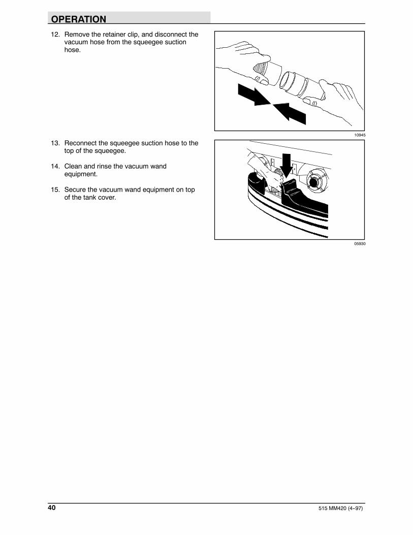
12. Remove the retainer clip, and disconnect thevacuum hose from the squeegee suctionhose.
13. Reconnect the squeegee suction hose to thetop of the squeegee.
14. Clean and rinse the vacuum wandequipment.
15. Secure the vacuum wand equipment on topof the tank cover.
10945
05930

OPERATION
41515 MM420 (6--00)
POWER WAND
The power wand uses the machine’s vacuum andsolution systems. The power wand allowsscrubbing of floors that are out of reach of themachine.
WARNING: Flammable materials orreactive metals can cause an explosionor fire. Do not pickup.
1. Turn the machine power off.
FOR SAFETY: Before leaving orservicing machine; stop on levelsurface, turn off machine.
2. Set the parking brake.
3. Remove the power wand equipment fromthe tank cover.
4. Remove the squeegee suction hose fromthe top of the rear squeegee.
08067

OPERATION
515 MM420 (4--96)42
5. Connect the vacuum wand hose and thesqueegee suction hose with the adaptor.
6. Attach the end of solution hose to thequick-disconnect. Push the connector in untilit stops. Pull on the hose to make sure it isconnected.
7. Attach the other ends of the solution andvacuum hoses to the power wand.
8. Turn the machine power on.
10945
07320

OPERATION
43515 MM420 (1--96)
9. Press the rear squeegee switch to turn onthe vacuum.
10. Switch the power wand on.
11. Squeeze the solution lever on the powerwand to spray solution on the floor. Scrubthe floor with the brush side of the cleaningtool.
12. Vacuum up the solution by turning over thecleaning tool so the squeegee side is down.
10885
06601
06202
OPERATION
515 MM420 (1--96)44
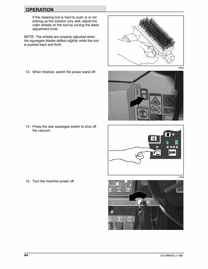
If the cleaning tool is hard to push or is notpicking up the solution very well, adjust theroller wheels on the tool by turning the blackadjustment knob.
NOTE: The wheels are properly adjusted whenthe squeegee blades deflect slightly while the toolis pushed back and forth.
13. When finished, switch the power wand off.
14. Press the rear squeegee switch to shut offthe vacuum.
15. Turn the machine power off.
06604
10885

OPERATION
45515 MM420 (4--96)
16. Disconnect the solution hose from themachine.
17. Remove the vacuum hose from thesqueegee suction hose.
18. Reconnect the squeegee suction hose to thesqueegee.
19. Disconnect the other ends of the solutionand vacuum hoses from the power wand.
20. Secure the power wand equipment on top ofthe tank cover.
10946
05930
07321

OPERATION
515 MM420 (1--96)46
MACHINE TROUBLESHOOTING
Problem Cause Remedy
Trailing water -- poor or no waterpickup.
Worn rear squeegee blades. Rotate or replace squeegeeblades.pickup.
Rear squeegee out ofadjustment.
Adjust rear squeegee.
Side squeegees raised. Lower side squeegees.
Worn side squeegee blades. Replace side squeegee blades.
Side squeegees out ofadjustment.
Adjust side squeegees.
Too much solution flow to floor. Reduce solution flow to floor.
Vacuum hose clogged. Flush vacuum hoses.
Recovery tank full. Drain recovery tank.
Float stuck shutting off vacuum. Clean float.
Debris caught on rear squeegee. Remove debris.
Foam filling recovery tank. Empty recovery tank; use less orchange detergent.
Vacuum hose to rear squeegeedisconnected or damaged.
Reconnect or replace vacuumhose.
Vacuum fan to recovery tankhose damaged.
Replace hose.
Vacuum fan will not turn on Recovery tank full Drain recovery tankVacuum fan will not turn on
Foam filling recovery tank Empty recovery tankFoam filling recovery tank
Use less or change detergent
Use a defoamer
Vacuum fan circuit breakertripped
Reset circuit breaker
Vacuum fan failure Contact Tennant servicerepresentative
Little or no solution flow to thefloor.
Solution tank empty. Fill solution tank.Little or no solution flow to thefloor. Solution control linkage broken
or out of adjustment.Replace and/or adjust cable.
Solution supply lines plugged. Flush solution supply lines.
ESt switch off. Turn ESt switch on.
Poor scrubbing performance. Debris caught on scrub brushes. Remove debris.Poor scrubbing performance.
Improper detergent or brushesused.
Check with TENNANTrepresentative for advice.
Worn scrub brushes. Replace scrub brushes.
ESt system does not fill solutiontank.
Clogged solution pump or lines. Flush ESt system.ES system does not fill solutiontank. ESt float switch(es) stuck. Clean switch floats of debris.
Clogged ESt filter. Clean filter.
Water levels too low in tanks. Add water.

OPERATION
47515 MM420 (9--98)

MAINTENANCE
515 MM420 (9--98)48
MAINTENANCE
32 7 8 9 6 12 142
1
1145 6 6
4
7 8
4 6
13
10
15
16
10656
MAINTENANCE CHART
Interval Key Description ProcedureLubricant/
Fluid
No. ofServicePoints
Daily 5 Rear Squeegee Check for damage, wear and ad-justment
-- 1
7 Side Squeegees Check for damage and wear -- 28 Scrub brushes Check for damage and wear -- 23 Recovery tank Clean -- 13 Recovery tank, ESt mode Clean ESt filter -- 11 Vacuum fan inlet filter Clean -- 12 Solution tank, ESt mode Clean and flush -- 1
16 Vacuum fan filter Clean and flush -- 1-- Machine Check for leaks -- 1
50 Hours 10 Scrub head floor skirts Check for damage and wear -- 550 Hours 10 Scrub head floor skirts Check for damage and wearand adjust
-- 5
-- Battery Check electrolyte level -- 1

MAINTENANCE
49515 MM420 (3--99)
Interval Key Description ProcedureLubricant/
Fluid
No. ofServicePoints
100 Hours 4 Tires Check for damage -- 3100 Hours14 Propelling gearbox Check lubricant level GL 114 Front wheel support Lubricate SPL 214 Front wheel support
bearingLubricate SPL 2
6 Scrub head parallel Lubricate SPL 8(4)6 Scrub head parallelarm pivot points
Lubricate SPL 8(4)
Steering universal joint Lubricate SPL 211 Brakes Check adjustment -- 115 Rear squeegee caster Lubricate SPL 1
500 Hours 13 Vacuum fan motor Check motor brushes -- 2(3)500 Hours12 Steering gear chain H Check tension and lubricate GL 114 Front wheel H Torque wheel nuts -- 16 Scrub head gas spring Check for wear and operation -- 1
1000Hours
14 Propelling gearbox H Change gear lubricant GL 11000Hours
14 Propelling gearboxH Change fill-level plug seals -- 1
9 Scrubbing brush drive Check motor brushes -- 2(3)9 Scrubbing brush drivemotors
Check motor brushes -- 2(3)
14 Propelling motor Check motor brushes -- 1
SPL -- Special lubricant, Lubriplate EMB grease (Tennant part no. 01433--1)GL -- SAE 90 weight gear lubricant
NOTE: Also check procedures indicated (H) after the first 50-hours of operation.

MAINTENANCE
515 MM420 (1--96)50
LUBRICATION
PROPELLING GEARBOX
Check the lubricant level in the propelling gearboxevery 100 hours of operation. Change the gearlubricant, and the drain and fill-level plug sealsafter the first 50 hours of operation, and thenevery 1000 hours of operation. Use SAE 90weight gear lubricant.
FRONT WHEEL SUPPORT BEARING
The front wheel support has two grease fittings forthe bearing. Raise the machine so the front wheelis off the floor. Fill one of the grease fittings whilerotating the gearbox from stop to stop. Fill thesecond grease fitting while rotating the gearboxback to the original position. The bearing cavity isfull when grease comes out of the fittings, or outof the top seal.
Lubricate with Lubriplate EMB grease (Tennantpart no. 01433--1) every 100 hours of machineoperation, or after steam cleaning the gearboxarea.
FOR SAFETY: When servicing machine,block machine tires before jackingmachine up.
FOR SAFETY: When servicing machine,jack machine up at designated locationsonly. Block machine up with jackstands.
STEERING UNIVERSAL JOINT
The steering universal joint has two greasefittings. Lubricate with Lubriplate EMB grease(Tennant Part No. 01433--1) every 100 hours ofoperation.
05934
05934

MAINTENANCE
51515 MM420 (4--96)
SCRUB HEAD PARALLEL ARMS
The scrub head parallel arms have a grease fittingat each of the eight pivot points. Lubricate withLubriplate EMB grease (Tennant Part No.01433--1) every 100 hours of operation.
05917
05919
MAINTENANCE
515 MM420 (3--99)52
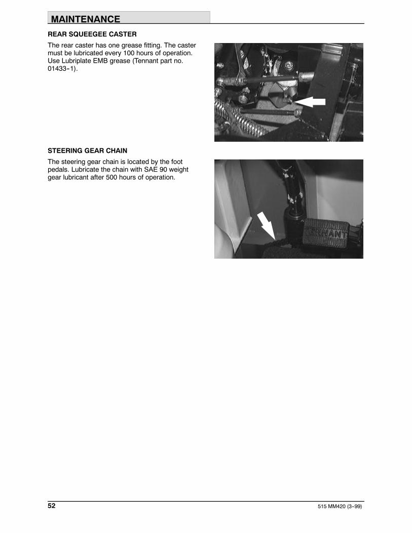
REAR SQUEEGEE CASTER
The rear caster has one grease fitting. The castermust be lubricated every 100 hours of operation.Use Lubriplate EMB grease (Tennant part no.01433--1).
STEERING GEAR CHAIN
The steering gear chain is located by the footpedals. Lubricate the chain with SAE 90 weightgear lubricant after 500 hours of operation.

MAINTENANCE
53515 MM420 (10--96)
BATTERIES
The batteries are unique in that they hold theirpower for long periods of time. The lifetime of thebatteries is limited by the number of charges thebatteries receive. To get the most life from thebatteries, charge them when all the batterydischarge indicator segments shut off (20%charge left). Use an automatic charger with theproper rating for the batteries.
Periodically clean the top surface of the batteriesand the terminals, and check for looseconnections. Use a strong solution of baking sodaand water. Brush the solution sparingly over thebattery tops, terminals, and cable clamps. Do notallow any baking soda solution to enter thebatteries. Use a wire brush to clean the terminalposts and the cable connectors. After cleaning,apply a coating of clear battery post protectant tothe terminals and the cable connectors. Keep thetops of the batteries clean and dry.
Keep all metallic objects off the top of thebatteries, which may cause a short circuit.Replace any worn or damaged wires.
Check the electrolyte level in each battery aftercharging, and every 50 hours of operation. Neveradd acid to the batteries, only distilled water.Always keep the battery caps on, except whenadding water or taking hydrometer readings.
Measuring the specific gravity, using ahydrometer, is a way to determine the chargelevel and condition of the batteries. If one or moreof the battery cells test lower than the otherbattery cells (0.050 or more), the cell is damaged,shorted, or is about to fail.
04380

MAINTENANCE
515 MM420 (10--96)54
NOTE: Do not take readings immediately afteradding distilled water. If the water and acid are notthoroughly mixed, the readings may not beaccurate. Check the hydrometer readings againstthe following chart to determine the remainingbattery charge level:
SPECIFIC GRAVITY at27_ C (80_ F)
BATTERYCHARGE
1.290 100% Charged
1.252 75% Charged
1.200 50% Charged
1.177 25% Charged
1.140 Discharged
NOTE: If the readings are taken when the batteryelectrolyte is any temperature other than 27_ C(80_ F), the reading must be temperaturecorrected. Add or subtract to the specific gravityreading 0.004, 4 points, for each 6_ C (10_ F)above or below 27_C (80_ F).
CHARGING THE BATTERIES
1. Drive the machine to a flat, dry surface in awell-ventilated area.
2. Turn the machine power off and set theparking brake.
FOR SAFETY: Before leaving orservicing machine; stop on levelsurface, turn off machine.
3. Open the machine cover.
WARNING: Batteries emit hydrogengas. Explosion or fire can result. Keepsparks and open flame away. Keepcovers open when charging.
4. Remove the seat support.
05916

MAINTENANCE
55515 MM420 (10--96)
5. Check the water level in all the battery cells.If the level is low, add just enough distilledwater to cover the plates. DO NOTOVERFILL. The batteries can overflowduring charging due to expansion.
NOTE: Make sure the battery caps are in placewhile charging.
FOR SAFETY: When maintaining orservicing machine, avoid contact withbattery acid.
6. Unplug the battery connector from themachine connector.
7. Plug the charger connector into the batteryconnector.
8. Plug the battery charger into the wall outlet.
NOTE: If the red “ABNORMAL CYCLE” lamplights when the TENNANT charger is plugged intoa wall outlet, the charger can not charge thebattery and there is something wrong with thebattery.
9. The Tennant charger will start automatically.When the batteries are fully charged, theTennant charger will automatically turn off.
NOTE: Use a charger with the proper rating forthe batteries to prevent damage to the batteries orreduce the battery life.
NOTE: If the charger needs to be disconnectedfrom the machine before the batteries are fullycharged and the charger has not automaticallyshut off, turn off the charger before disconnectingit.
10. After the charger has turned off, unplug thecharger from the wall outlet.
11. Unplug the charger connector from thebattery connector on the machine.
FOR SAFETY: When maintaining orservicing machine, avoid contact withbattery acid.
08247
07224

MAINTENANCE
515 MM420 (4--96)56
12. Reconnect the battery connector to themachine connector.
13. Check the electrolyte level in each batterycell. Add just enough distilled water to bringthe electrolyte level up to the bottom of thefill rings.
14. Replace the seat support.
15. Close the machine cover.
CONTROL PANEL
The control panel can be used to run aself-diagnostic test of the machine electricalcomponents and system. When theself-diagnostic test is running, motors andactuators on the machine will activate.
FOR SAFETY: When servicing machine,avoid moving parts. Do not wear loosejackets, shirts, or sleeves.
1. Turn the machine power off.
2. While pressing the squeegee switch, turnthe machine power on. Continue pressingthe squeegee switch a few seconds, thenrelease the switch.
3. While the diagnostic is running, the machinesystems will activate as follows:
D The brushes and squeegee raise.
D The vacuum fan starts and thesqueegee lowers. The squeegee raisesand the vacuum fan shuts off.
D The scrub head lowers and moves outto the edge scrub position. The scrubhead moves back in again and raises.
D The brushes turn on and off.
D The solution tank auto-fill valve turns onand off.
D The ESt pump turns on and off, if themachine has the ESt option.
D The vacuum fan starts and shuts off.
D The brushes turn on and off.
10734

MAINTENANCE
57515 MM420 (4--96)
D The recovery tank auto-fill valve turnson and off.
4. If the electrical system passes theself-diagnostic test, an OK message willappear on the control panel display.
If the self-diagnostic test finds an error in thesystem, an error message will appear on thecontrol panel display. Note the errormessage displayed, and contact the servicepersonnel.
5. Turn off the diagnostic by turning off themachine power.
ELECTRIC MOTORS
The carbon brushes on the vacuum fan motorsshould be inspected every 500 hours of machineoperation. The brush drive motors and propellingmotor should be inspected every 1000 hours ofoperation.
PROPELLING CIRCUIT
The propelling circuit is a transistorized controller.It controls the forward and reverse speed of themachine and is located in the controller panel.The circuit cannot be serviced by the user -- onlytrained personnel should be allowed to work on it.Do not steam clean or spray the panel with waterbecause the electrical system may be damaged.
NOTE: A static discharge grounding strap shouldbe used when servicing the electronic circuitry.
SCRUB HEAD
The machine can be equipped with either aMaxProt 1000 or MaxProt 1200 scrub head.The MaxProt 1000 is the standard two diskbrush scrub head. The optional MaxProt 1200 isa three disk brush scrub head. The scrub headfloor skirts control water spray from the brushes.
10734

MAINTENANCE
515 MM420 (4--96)58
SCRUB HEAD FLOOR SKIRTS
The skirts are located in front and rear of thescrub head. Check these skirts for wear anddamage every 50 hours of operation.
The skirts should clear the floor by 0 to 6 mm(0 to 0.25 in) when the scrub head is down. Checkthe floor skirt adjustment every 50 hours ofoperation.
The rear scrub head floor skirts can be adjustedby pulling the skirt up or down without looseningthe retainer hardware.
The front scrub head floor skirts need the retainerhardware loosened to move the skirt up or down.Tighten the retainer hardware enough to hold theskirt firmly in place.
SCRUB HEAD GAS SPRING
Check the scrub head gas spring for wear andproper operation every 500 hours of operation.
SCRUB HEAD ADJUSTMENTS
The scrub head is factory adjusted, and themeasurements should not be changed unlessscrub head parts are damaged or are replaced.
SCRUB BRUSHES
Check the scrub brushes daily for wire or stringtangled around the brush or brush drive hub. Alsocheck the brushes for any damage and wear.
The scrub brushes should be replaced if largeamounts of bristles are missing, or if theremaining bristles’ length is less than 6 mm(0.25 in).
NOTE: Be sure to replace brushes in sets.Otherwise one brush will be more aggressive thanthe other.
Cleaning pads must be placed on pad drivesbefore they are ready to use. The cleaning pad isheld in place by a pad holder.
Cleaning pads need to be cleaned immediatelyafter using with soap and water. Do not wash thepads with a pressure washer. Hang dry pads, orlie flat to dry.
05937

MAINTENANCE
59515 MM420 (4--96)
REPLACING THE SCRUB BRUSHES
1. Raise the scrub head.
2. Turn the machine power off and set theparking brake.
FOR SAFETY: Before leaving orservicing machine; stop on levelsurface, set parking brake, turn offmachine and remove key.
3. Push back on the side squeegee releaselever. Pull up on the side squeegeeassembly and remove it from the scrubhead. Repeat for the other side of the scrubhead.
NOTE: Remove the suction hose from theright-hand side squeegee assembly on theMaxProt 1200 scrub head.
4. Press the brush spring clip ends togetherwith your thumb and index finger to removethe scrub brush. Repeat for the other brushor brushes.
5. For the MaxProt 1200 scrub head, startwith the center brush. Slide the new scrubbrush under the scrub brush drive assembly.
6. Line up the scrub brush drive socket with thedrive plug.
7. Lift and snap the scrub brush onto the driveplug.
8. Check to make sure the brush is securelymounted on the brush hub.
9. Push back on the side squeegee releaselever. Slide the side squeegee assemblyonto the scrub head. Repeat on the otherside of the scrub head.
NOTE: Reconnect the suction hose to theright-hand side squeegee assembly on theMaxProt 1200 scrub head.
10. Check the scrub head front and rear skirtadjustments as described in SCRUB HEADFLOOR SKIRTS.
05938
05939

MAINTENANCE
515 MM420 (9--98)60
SOLUTION SYSTEM
SOLUTION VALVE
The solution valve controls the flow of solution tothe scrub brushes. The valve linkage shouldprovide the valve with fully open to fully closedpositions.
The solution control cable can be adjusted at thesolution lever or valve ends of the cable. To adjustthe cable at the solution lever end, open themachine cover. To adjust the cable at the solutionvalve end of the cable, locate the valve by thescrub head. Adjust the cable with the valve in theoff position.
The solution lever has two mounting holes for thesolution cable clevis. In the factory, the cable ismounted on the inside hole. The cable clevis canbe moved to the outside hole for greater solutionflow to the floor. This mounting position would befor rough floor conditions only.
RECOVERY TANK
The recovery tank stores recovered solution.
The recovery tank should be drained and cleaneddaily, after the solution tank is empty, wheneverthe float stops the vacuum fan, or the recoverytank full indicator lights. See DRAINING ANDCLEANING THE TANKS section of this manual.
05941
06011

MAINTENANCE
61515 MM420 (9--98)
For machines serial number 004868 and above,the vacuum fan filter should be cleaned daily. SeeDRAINING AND CLEANING THE TANKS sectionof this manual.
ESt option: The ESt filter should be cleaneddaily.
The outside of the tank can be cleaned with vinylcleaner.
SOLUTION TANK
The solution tank stores the cleaning solution.
The solution tank does not require regularmaintenance. If deposits form on the bottom ofthe tank, rinse the tank with a strong blast ofwarm water. The tank can be flushed through thefill opening. Drain the tank with the solution tankdrain hose.
ESt option: The solution tank should be drainedand cleaned daily.
10916
05921
05940

MAINTENANCE
515 MM420 (9--98)62
SQUEEGEES
As the machine travels forward the squeegeeswipe the dirty solution off the floor, which is thenpicked up and drawn into the recovery tank. Thefront blade channels the water, and the rear bladewipes the floor.
The side squeegees control water spray andchannel water into the path of the rear squeegee.
REAR SQUEEGEE
Check the squeegee blades for damage and weardaily. Rotate or replace either of the squeegeeblades if the leading edge is torn or worn half-waythrough the thickness of the blade.
The squeegee can be adjusted for leveling anddeflection. The deflection and leveling of thesqueegee blades should be checked daily, orwhen scrubbing a different type of floor.
LEVELING THE REAR SQUEEGEE
Leveling of the squeegee assures even contactthe length of the squeegee blade with the surfacebeing scrubbed. Make sure this adjustment isdone on an even, level floor.
1. Turn the machine power on.
2. Lower the squeegee.
3. Set the machine parking brake while thedriving machine slowly forward, and turn themachine power off.
FOR SAFETY: Before leaving orservicing machine; stop on levelsurface, set parking brake, turn offmachine and remove key.
4. Look at the deflection of the squeegeeblade, over the full length of the squeegeeblade.
MAINTENANCE
63515 MM420 (9--98)
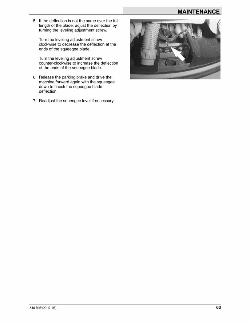
5. If the deflection is not the same over the fulllength of the blade, adjust the deflection byturning the leveling adjustment screw.
Turn the leveling adjustment screwclockwise to decrease the deflection at theends of the squeegee blade.
Turn the leveling adjustment screwcounter-clockwise to increase the deflectionat the ends of the squeegee blade.
6. Release the parking brake and drive themachine forward again with the squeegeedown to check the squeegee bladedeflection.
7. Readjust the squeegee level if necessary.

MAINTENANCE
515 MM420 (4--96)64
ADJUSTING REAR SQUEEGEE BLADEDEFLECTION
Deflection is the amount of curl the squeegeeblade has when the machine moves forward withthe squeegee lowered to the floor. The bestdeflection is when the squeegee wipes the floorjust dry with a minimum amount of deflection.
1. Turn the machine power on.
2. Lower the squeegee.
3. Set the machine parking brake while drivingthe machine slowly forward, and turn themachine power off.
FOR SAFETY: Before leaving orservicing machine; stop on levelsurface, set parking brake, turn offmachine and remove key.
4. Look at the deflection of the squeegeeblade. The correct amount of deflection is15 to 20 mm (0.50 to 0.75 in).
5. To adjust the amount of deflection, loosenthe caster jam nut. Turn the caster shaftusing the flats.
Turn the shaft clockwise to decrease theblade deflection. Turn the shaftcounter-clockwise to increase bladedeflection. Tighten the jam nut.
6. Release the parking brake and drive themachine forward again to check thesqueegee blade deflection.
7. Readjust the squeegee blade deflection ifnecessary.
03719
15 to 20 mm(0.50 to 0.75 in)

MAINTENANCE
65515 MM420 (4--96)
SIDE SQUEEGEE ADJUSTMENT
The side squeegee has one adjustment; height.To change the height adjustment, disconnect thesqueegee spring from the clevis pin and move theclevis pin to a different hole location. The factorysetting is in the middle hole location.
SQUEEGEE BLADES
The rear squeegee assembly channels water intothe vacuum fan suction. The front blade channelsthe water, and the rear blade wipes the floor.
The side squeegees control water spray andchannel water into the path of the rear squeegee.
Replace any worn or damaged squeegee blades.
REAR SQUEEGEE BLADES
Check the squeegee blades for damage and weardaily. Rotate or replace either of the squeegeeblades if the leading edge is torn or worn half-waythrough the thickness of the blade.
The squeegee has two squeegee blades, the frontand rear. Each blade has four wiping edges. Touse them all, start with one wiping edge. To usethe next wiping edge, rotate the bladeend-for-end. To use the next wiping edge, rotatethe top edges down, bottom edges up. To use thelast edge, rotate the blade end-for-end.
REPLACING OR ROTATING THE REARSQUEEGEE BLADES
1. Make sure the squeegee is raised off thefloor.
2. Turn the machine power off and set theparking brake.
FOR SAFETY: Before leaving orservicing machine; stop on levelsurface, turn off machine.
05918

MAINTENANCE
515 MM420 (4--96)66
3. Remove the ringed pin, deflector, gasket,retainer bracket, and retainer strip from theend of the squeegee.
4. Pull off the squeegee assembly cover.
5. Pull the squeegee blade off the squeegeeframe.
6. Replace or rotate the squeegee to allow anew edge to face the front of the machine.
7. Slide the squeegee blade onto the squeegeeframe.
NOTE: Lubricating the squeegee frame wherethe squeegee makes contact will make it easier toinstall the squeegee blade.
8. Slip the retainer strip into the squeegeeblade. Slip the retainer bracket on the end ofthe squeegee frame. Place the squeegeegasket on the end of the squeegee framewith the long end down and back.
9. Replace the squeegee assembly cover.
10. Replace the deflector and the ringed pin.
11. Adjust the rear squeegee as described inLEVELING THE REAR SQUEEGEE andADJUSTING REAR SQUEEGEE BLADEDEFLECTION.
SIDE SQUEEGEES BLADES
The side squeegees control water spray andchannel water into the path of the rear squeegee.Check the side squeegees for damage and weardaily.
Replace the side squeegee blades whenever theybecome damaged or lose their shape orresiliency. Replace the squeegee deflectorswhenever they become worn.
05943
05945
MAINTENANCE
67515 MM420 (4--96)
REPLACING SIDE SQUEEGEE BLADES
1. Raise the scrub head.
2. Turn the machine power off and set theparking brake.
FOR SAFETY: Before leaving orservicing machine; stop on levelsurface, set parking brake, turn offmachine and remove key.
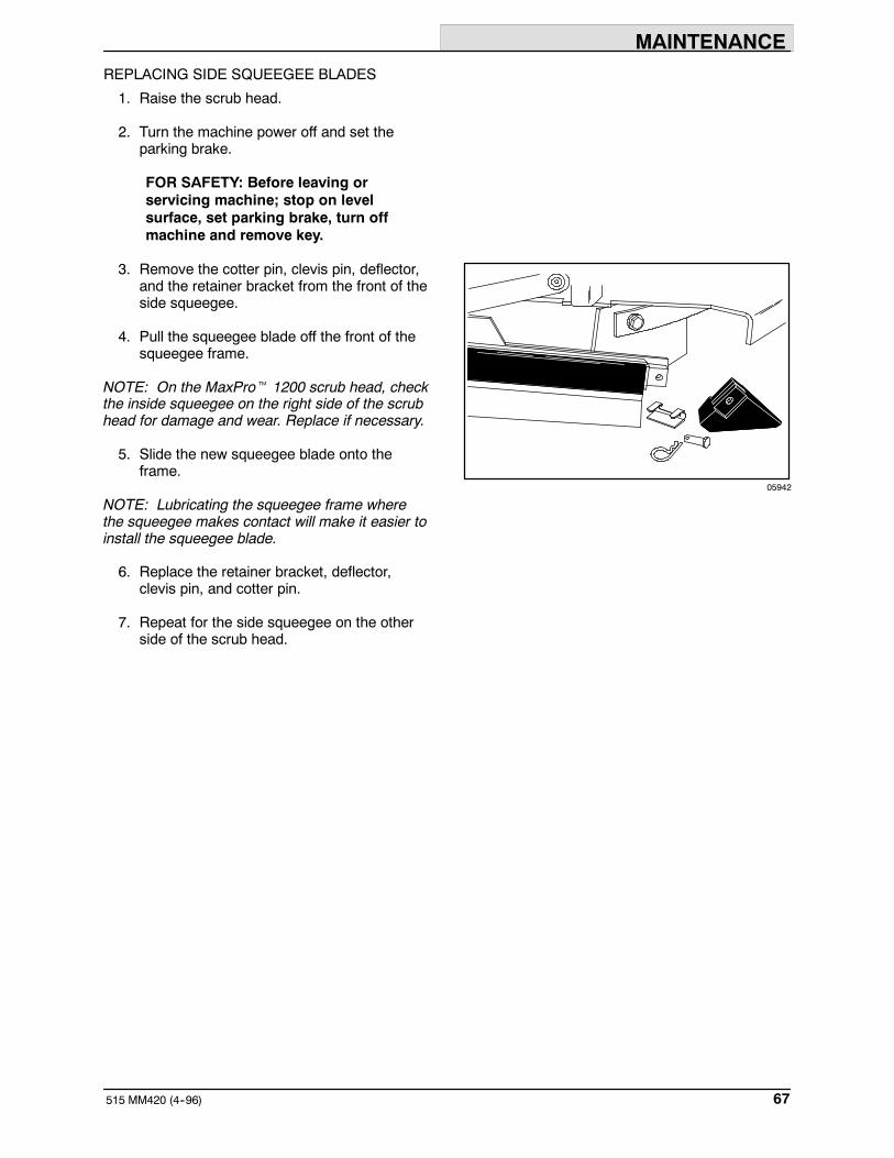
3. Remove the cotter pin, clevis pin, deflector,and the retainer bracket from the front of theside squeegee.
4. Pull the squeegee blade off the front of thesqueegee frame.
NOTE: On the MaxProt 1200 scrub head, checkthe inside squeegee on the right side of the scrubhead for damage and wear. Replace if necessary.
5. Slide the new squeegee blade onto theframe.
NOTE: Lubricating the squeegee frame wherethe squeegee makes contact will make it easier toinstall the squeegee blade.
6. Replace the retainer bracket, deflector,clevis pin, and cotter pin.
7. Repeat for the side squeegee on the otherside of the scrub head.
05942

MAINTENANCE
515 MM420 (4--96)68
CHAINS
STEERING GEAR CHAIN
The steering gear chain tension should bechecked after the first 50 hours of operation andevery 500 hours there after. The deflection shouldbe 3 to 6 mm (0.12 to 0.25 in) between thesteering sprocket and the idler sprocket when thesteering wheel is turned the tightest position eitherdirection.
STATIC DRAG CHAIN
A static drag chain prevents the buildup of staticelectricity in the machine. The chain is attached tothe transaxle.
Make sure the chain is always touching the floor.
05936

MAINTENANCE
69515 MM420 (4--96)
BRAKES AND TIRES
BRAKES
The foot brake and the parking brake operate thelinkage that controls the brakes on the rearwheels.
The parking brake should be adjusted after every100 hour of operation or whenever it becomesvery easy to engage.
To adjust the parking brake, turn the knurled knobon the end of the parking brake levercounter-clockwise.
The foot pedal should not travel more than 25 mm(1 in) to engage the brake. Check the brakeadjustment after every 100 hours of operation.
Park the machine on a level surface. Turn themachine power off, and block the machine tires.
Loosen the adjustment nuts. Adjust the brakecable with one nut and lock in place with the othernut.
Adjust the brake cable so that the brake pedaltravels no more than 25 mm (1 in) to fully engagethe brakes. Readjust the brake cable if necessary.
Remove the blocks from the machine tires.
TIRES
All the machine tires are solid. Check the tires forwear every 100 hours of operations.
FRONT WHEEL
Torque the front wheel nuts to 122 to 155 Nm(90 to 110 ft lb) after the first 50 hours ofoperation, and every 500 hours of operation.
05947

MAINTENANCE
515 MM420 (6--00)70
PUSHING, TOWING, AND TRANSPORTINGTHE MACHINE
PUSHING OR TOWING THE MACHINE
If the machine becomes disabled, it can bepushed from the front or rear, but tow it only fromthe rear.
Only push or tow the machine for a very shortdistance and do not exceed 3.2 kp/h (2 mph). It isNOT intended to be pushed or towed for a longdistance or at a high speed.
ATTENTION! Do not push or towmachine for a long distance or damagemay occur to the propelling system.

MAINTENANCE
71515 MM420 (6--00)
TRANSPORTING THE MACHINE
1. Position the rear of the machine at theloading edge of the truck or trailer.
2. If the loading surface is not horizontal or ishigher than 380 mm (15 in) from the ground,use a winch to load machine.
If the loading surface is horizontal AND is380 mm (15 in) or less from the ground, themachine may be driven onto the truck ortrailer.
3. To winch the machine onto the truck ortrailer, attach the winching chains at thebottom of the rear bumper.
If the machine has the optional rear tie downbrackets, attach the winching chains tothem.
FOR SAFETY: When loading machineonto truck or trailer, use winch. Do notdrive the machine onto the truck ortrailer unless the loading surface ishorizontal AND is 380 mm (15 in) or lessfrom the ground.
4. Position the machine onto the truck or traileras far as possible. If the machine starts toveer off the centerline of the truck or trailer,stop and turn the steering wheel to centerthe machine.

MAINTENANCE
515 MM420 (6--00)72
5. Set the parking brake and block the machinetires. Tie down the machine to the truck ortrailer before transporting.
The tie down locations are at each corner ofthe machine fram.
If the machine has the optional tie downbrackets, attach the winching chains tothem.
6. If the loading surface is not horizontal or ishigher than 380 mm (15 in) from the ground,use a winch to unload machine.
If the loading surface is horizontal AND is380 mm (15 in) or less from the ground, themachine may be driven off the truck ortrailer.
FOR SAFETY: When unloading machineoff truck or trailer, use winch. Do notdrive the machine off the truck or trailerunless the loading surface is horizontalAND 380 mm (15 in) or less from theground.
MAINTENANCE
73515 MM420 (6--00)
MACHINE JACKING
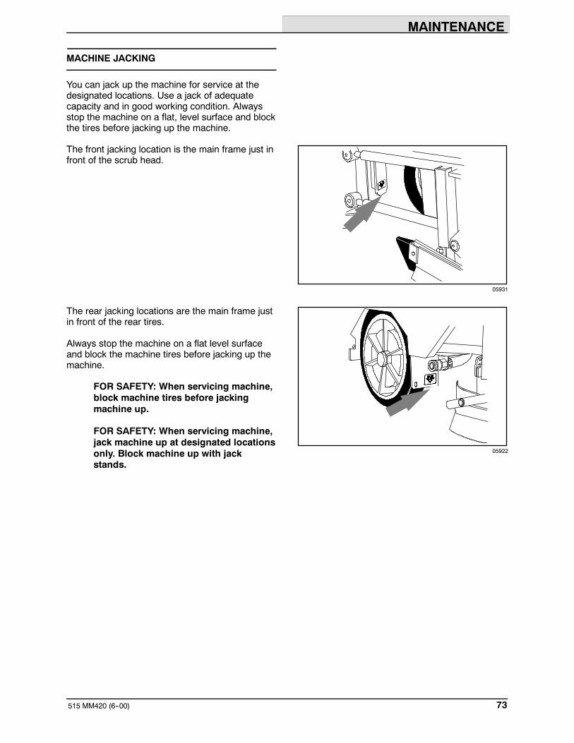
You can jack up the machine for service at thedesignated locations. Use a jack of adequatecapacity and in good working condition. Alwaysstop the machine on a flat, level surface and blockthe tires before jacking up the machine.
The front jacking location is the main frame just infront of the scrub head.
The rear jacking locations are the main frame justin front of the rear tires.
Always stop the machine on a flat level surfaceand block the machine tires before jacking up themachine.
FOR SAFETY: When servicing machine,block machine tires before jackingmachine up.
FOR SAFETY: When servicing machine,jack machine up at designated locationsonly. Block machine up with jackstands.
05931
05922

MAINTENANCE
515 MM420 (6--00)74
STORAGE INFORMATION
The following steps should be taken when storingthe machine for extended periods of time.
1. Drain and clean the solution and recoverytanks.
ESt machines: Run clean water throughthe solution system and the ESt solutionpump.
2. Raise the rear squeegee and the scrubhead.
3. Park the machine in a cool, dry area.
4. Remove the batteries, or charge them afterevery three months.

SPECIFICATIONS
75515 MM420 (4--96)
SPECIFICATIONS
GENERAL MACHINE DIMENSIONS/CAPACITIES
Item Dimension/capacity
Length 2110 mm (83 in)
Width, frame 1070 mm (42 in)
Width, rear squeegee 1210 mm (47.5 in)
Width with MaxProt 1200 scrub head option 1295 mm (51 in)
Height 1450 mm (57 in)
Height with overhead guard option 2035 mm (80 in)
Scrub brush diameter 510 mm (20 in)
Scrubbing path width 1015 mm (40 in)
Solution tank capacity 210 L (55 gal)
Recovery tank capacity 190 L (50 gal)
Tank capacity with ESt option 340 L (90 gal)
Propelling gear box 90 weight gear lubricant capacity 2.6 L (2.7 qt)
GVWR 2087 kg (4600 lb)
GENERAL MACHINE PERFORMANCE
Item Measure
Maximum forward speed 8 km/h (5mph)
Maximum reverse speed 4.8 km/h (3mph)
Aisle turnaround width 2290 mm (90 in)
Maximum rated climb and descent angle with empty tanks 8.5_
Maximum rated climb and descent angle with full tanks 6_

SPECIFICATIONS
515 MM420 (4--96)76
POWER TYPE
Type Quantity Volts Ah Rating Weight
Batteries 1 36 380 @ 6 hr rate 436 kg (960 lb)Batteries
1 36 420 @ 6 hr rate 585 kg (1290 lb)
1 36 690 @ 6 hr rate 850 kg (1875 lb)
Type Use VDC Kw (hp)
Electric Motors Scrub brush 36 0.75 (1)Electric Motors
Heavy duty scrub brush 36 1.12 (1.5)
Vacuum fan 36 0.63 (0.85)
Propelling 36 2.2 (3)
Type VDC amp Hz Phase VAC
Chargers 36 120 60 1 208--240--480
36 120 60 3 208--240--480
36 120 50 1 208--240--480
36 120 50 3 208--240--480
36 75 50 1 208--240--480
36 75 60 1 208--240--480
36 75 60 3 208--240--480
36 50 60 1 240
36 50 50 1 230
36 45 50 and 60 1 200
STEERING
Type Power source Emergency steering
Front wheel controlled, universaljoint to gear and chain
Manual Manual
BRAKING SYSTEM
Type Operation
Service brakes Mechanical drum brakes (2), one per rear wheel, cable actuated
Parking brake Utilizes service brakes, cable actuated
TIRES
Location Type Size
Front (1) Solid 16.25 x 6
Rear (2) Solid 16 x 3.5

SPECIFICATIONS
77515 MM420 (4--96)
2035 mm(80 in)
2110 mm (83 in)
1070 mm(42 in)
1450 mm(57 in)
TOP VIEW
SIDE VIEW10656
MACHINE DIMENSIONS

INDEX
515 MM420 (6--00)78
INDEX
A
Adjusting rear squeegee blade deflection, 64
AdjustmentsParking brake, 69Service brakes, 69
Aisle turn, 75
Ajustments, Steering gear chain, 68
B
Batteries, 53–56Charge level, 35Charger specifications, 76Charging, 54–56Discharge indicator, 11Maintenance, 53Specifications, 76
Battery charge level, 35
Battery discharge indicator, 11
Brake pedal, 9
Brakes, 69Parking, 17
Braking system, Specifications, 76
Brush, 35
BrushesScrub, 58Scrubbing, 25
Button, Horn, 16
C
Capacities, 75
Chain, Steering gear, 52
Chains, 68Static drag, 68Steering gear, 68
Changing message display language, 13
Circuit breakers, 18
Control panel, 15Battery discharge indicator, 11Changing message display language, 13Edge scrub switch, 14ESt switch, 14Hourmeter, 11Message display, 12Operating lights switch, 16Rear squeegee switch, 14Recovery tank full indicator, 13
Controls, 8Battery discharge indicator, 11Brake pedal, 9Circuit breakers, 18Control panel message display, 12Directional pedal, 9Edge scrub, 14ESt switch, 14Horn button, 16Hourmeter, 11On-off key switch, 16Operating lights switch, 16Power wand switch, 17Rear squeegee switch, 14Recovery tank full indicator, 13Scrub switch, 15Solution flow lever, 10Steering wheel, 10
D
Dimensions, 75
Directional pedal, 9
Double scrubbing, 28
Draining and cleaning the tanks, 31–33, 36
E
Edge scrub switch, 14
Electric motors, 57, 76
ElectricalBatteries, 53–56Charging batteries, 54–56Circuit breakers, 18
Electronics, Propelling circuit, 57
EStAuto-fill, 24Draining and cleaning tanks, 36Filling the tanks, 22–24
ESt switch, 14
F
Filling the tanks, 22–24
Front wheelSupport bearing, 50Torque, 69
Front wheel support bearing, 50

INDEX
79515 MM420 (6--00)
H
Hazard light switch, 16
Horn button, 16
Hoses, 36Recovery tank drain, 19Solution tank drain, 19
Hourmeter, 11
How the machine works, 20
I
IndicatorsRecovery tank full, 13Scrub brush pressure, 15
J
Jack points, 73
Jacking, 73
L
Languages, Control panel message display, 12
Leveling the rear squeegee, 62
LeversParking brake, 17Solution flow, 10
Lights, Operating lights switch, 16
Locking up side squeegees, 28
Lubrication, 50Front wheel support bearing, 50Propelling gearbox, 50Rear squeegee casters, 52Scrub head parallel arms, 51Steering gear chain, 52Steering universal joint, 50
M
MachineJacking, 73Towing, 70Transporting, 70
Machine components, 6
Machine dimensions, 77
Machine leaks, 21, 36
Machine tie down location, 72
Maintenance, 48–72Intervals, 48Recommended, 5
Maintenance chart, 48
Message display, Control panel, 12
Motors, Electric, 57, 76
O
On-off key switch, 16
Operating lights switch, 16
Operation, 5–54
Operation on inclines, 36
Operator Responsibility, 5
Operator seat, 19
Options, 37–45ESt switch, 14Positive solution control drain, 19Power wand, 41–45Power wand switch, 17Vacuum wand, 37–40
P
Parking brake, 17, 69
Pedal, Directional, 9
Pedals, Brake, 9
Positive solution control drain, 19
Post-operation checklist, 35
Power wand, 41–45
Power wand switch, 17
Pre-operation checklist, 21
Propelling circuit, 57
Propelling gearbox, 50
Pushing or towing the machine, 70
R
Rated incline and descent, 75
Rear squeegee, 62Adjusting deflection, 64Leveling, 62
Rear squeegee blades, 65
Rear squeegee casters, 52
Rear squeegee switch, 14
Recovery tank, 60Drain hose, 19Draining and cleaning, 31–33Positive solution control drain, 19Tank full indicator, 13

INDEX
515 MM420 (6--00)80
Recovery tank drain hose, 19
Replacing rear squeegee blades, 65
Replacing side squeegee blades, 67
Replacing the scrub brush, 59
Rotating rear squeegee blades, 65
S
SafetyLabels, 4Precautions, 3
Scrub brushes, 58Brush pressure, 15Replacing, 59
Scrub head, 57–63Adjustments, 58Floor skirts, 58Gas spring, 58Parallel arms lubrication, 51
Scrub head adjustments, 58
Scrub head floor skirts, 58
Scrub head gas spring, 58
Scrub head parallel arms, 51
Scrub switch, 15
Scrubbing, 26Brush information, 25Double, 28General information, 25Stop, 30
Scrubbing brushes, 25
Scrubbing pads, 26
Self-diagnostics, 56
Service records, 36
Side squeegee adjustment, 65
Side squeegee blades, 66
Side Squeegees, Locking up, 28
Side squeegeesAdjustment, 65Unlocking, 29
Skirts, Scrub head floor, 58
SolutionFilling the tanks, 22–24Flow lever, 10System, 60Tank drain hose, 19
Solution flow lever, 10
Solution System, 60
Solution system, Solution valve, 60
Solution Tank, 61
Solution tankDrain hose, 19Draining and cleaning, 31–33Filling, 22–24Positive solution control drain, 19
Solution tank drain hose, 19
Solution valve, 60
Specifications, 75–77Braking system, 76Chargers, 76Electric motors, 76Machine capacities, 75Machine dimensions, 75Machine performance, 75Power type, 76Steering, 76Tires, 76
Squeegee, 62–65Blades, 65Deflection, 21, 35
Squeegee blades, 65Rear, 65Replacing or rotating rear, 65Replacing side, 67Side, 66
Staring the machine, 22
Static drag chain, 68
Steering, Specifications, 76
Steering gear chain, 52, 68
Steering universal joint, 50
Steering wheel, 10
Stop scrubbing, 30
Stop the machine, 34
Storage information, 74
SwitchesEdge scrub, 14ESt, 14On-off key, 16Operating lights, 16Power wand, 17Rear squeegee, 14Scrub, 15
Symbol definitions, 7

INDEX
81515 MM420 (6--00)
T
TanksRecovery, 60Solution, 61
Tie down location, 72
Tires, 69–70Specifications, 76
Touch panel, Self-diagnostics, 56
Towing the machine, 70–71
Transporting the machine, 70–71
Troubleshooting, 46
U
Unlocking side squeegees, 29
V
Vacuum wand, 37–40

INDEX
515 MM420 (6--00)82